0 , ' & -!( ( (.-).- %- + (+ ,) / -(+...
TRANSCRIPT

122
This paper proposes a new simplified method for design, simulation, implementation, andobtaining optimum value of ac output filter to the SVPWM inverter fed induction motor using thebenefit of PSIM program is developed. Also a complex mathematical equations and transferfunctions are not desirable. The L-C filter cancels all harmonics and a real pure sinusoidal output voltage and current isobtained. Due to the flexibility of PSIM software, the values of L-C combination are obtained bytrial and error method. The advantage of this method, it can vary the values of inductor andcapacitor until the value of desired outcome is obtained. Experimental and simulation results have verified the superior performance and the effectivenessin reduction the harmonics of the proposed filter.
: Filter, SVPWM, Harmonics Analysis, Induction Motor, THD.
)output filter ()PSIM.(.)L-C
Filter ( .PSIM ،LC(Trial and Error)
. ه.

123
L InductiveC CapacitiveF FrequencyXm Leakage reactance (ohm)Xr Rotor reactance (ohm)Xs Stator reactance (ohm)Rr Rotor resistance (ohm)Rs Stator resistance (ohm)M Modulation indexSVPWM Space vector pulse width modulationTHD Total harmonic distortion
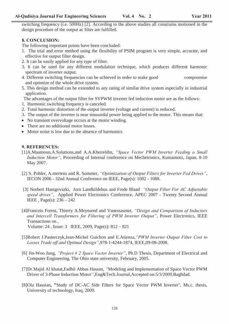
The SVPWM technique has become a popular PWM drive three-phase voltage source inverter fedac motors. These are widely used both in industrial and household applications [1].To achieve excellent performance of SVPWM drive induction motor, fast switching devices areused. But this also brings disadvantage effects:Firstly the waveform of output voltage and current contains a high amount of harmoniccomponents, which increase additional losses, and lower performance for the motor.Secondly, it causes higher switching losses in the inverter. The switching losses of the inverter arelinearly proportional to the switching frequency and of course the efficiency of the system isdecreased.Consequently, the most important compromising and mitigating of the above disadvantages are theuse of ac output filters for the SVPWM inverter.There are several different types of output filters are given for PWM techniques [2,3,4,5]. But in thecase of SVPWM technique is not found in literature any type of output filters, except a theoreticalproject for PH.D study [6]. The basic simple filter is a second order LC filter consisting of a seriesinductance and parallel capacitance. It has only two elements per phase that can be adjusted in thisstudy figure (1).
The space vector pulse width modulation (SVPWM) inverter fed three-phase induction motor wasbuilt in last year. The model is designed by imitating the conception of TMS320 (DSP) Microcontroller.The step by step of the whole system was explained, analyzed, and studied using MATLABSIMULINK without ac filter [7].The overall drive system such study, design, implementation and simulation for prototype modelare given in detail [8] using PSIM software.PSIM program provides a powerful and efficient environment for power electronics and motorcontrol simulation. PSIM’s graphic user interface is intuitive and very easy to use. A circuit can beeasily setup and edited. The simulation results can be analyzed easily using various post-processingfunction in the waveform display program.The PSIM features are:1. Simple use.2. Fast simulation.3. Flexible control representation.4. Built-in modules.5. Add-on modules.6. Parameter sweep.7. Runtime waveform display

124
PSIM’s simulation environment is interactive. It allows users to change parameters and monitorsimulation waveforms in the middle of a simulation run [9].
The blocks and their parameters of the system model are given in the following:1- Space vector calculation.2- Vector location3- Time interval calculation.4- Voltage source inverter motor drive system.5- L-C output filter.
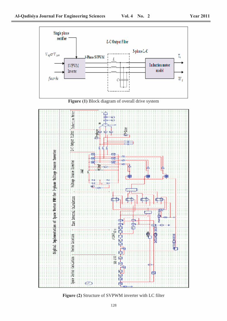
A single phase (full wave rectifier) is used as input power supply. A rectifier circuit is one which links an a.c supply to d.c load; it converts an alternating voltagesupply to direct voltage .The direct voltage so obtained is not normally level, as from battery, butare contains an alternating ripple component superimposed on the mean (d.c) level. Figure (2)shows the structure of whole system with LC output filter.
The task of the filter design is not simple. Complex mathematical equations and transferfunctions are needed. In addition, the filter size, cost, weight, and losses should be optimized.Besides that, it is constrained by the total harmonic distortion of the output voltage and current( , ,the voltage drop in the filter inductor, and the filter resonance frequency [3]. Alsothe dynamic effect of the filter over all system must be considered.Accordingly, new simplified method for design, implementation to get optimum value of LC outputfilter of the SVPWM drive induction motor using the benefits of characteristic of PSIM program isdeveloped.
The PSIM program is easily run to get the simulation results. In addition to that, all parametersin the following five parts of the SVPWM inverter drive system can be flexibly to be changed.1.Rectifier and L-C dc link.2.Three–phase MOSFET bridge SVPWM inverter switching frequency.3.Modulation index and ratio.4.Three –phase induction motor.5.A.C output filter. The name plate of the motor: 3-phase I.M, 380volt(line),1100watt,2pole, 2800rpm,50Hz. And thevalues Rs=6 , Xs=25.13 , Rr=15 (referred to stator) , Xr=12.5 (referred to stator) , andXm=300 .The output parameters of full-wave rectifier are and AC supply voltage is
volt with respect to the rated frequency (50Hz).The L & C of dc link is used to reduce the ripple content of the output voltage for the single
phase bridge rectifier. Its values have been selected such that the ripple factor lower than 10% [10].Then due to the flexibility of PSIM, the value of L-C combination is obtained by trials and errors.The advantage of this method, it can vary the values of inductor and capacitor until the desiredoutcome is obtained [11].The optimum value of L-C combination has been obtained in PSIM as:The trial and error method is run for different operating points, besides that all constrains andlimitation points mentioned in section (3) are considered. Figure (2) shows the structure ofSVPWM inverter with LC output filter.

125
All parameter values of the proposed system are given in section four. Also the optimum valueof L-C output ac filter is obtained using trial and errors method in PSIM program as:
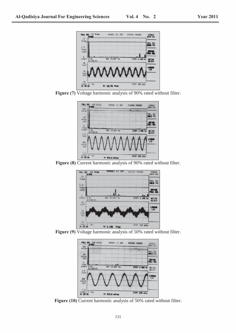
=8 .The results at no load operation are performed because the total harmonicdistortion THD is higher[7] . Two values of modulation index (90%and 50% of rated) is taken intocalculation to give all possible ranges of THD variation.The no load test of SVPWM inverter drive induction motor is obtained by applying the higher valueof modulation index (90%) and the lower possible value (50%). The phase voltage and phasecurrent SVPWM inverter are analyzed by using Fourier series. This analysis is done by using PSIMprogram to obtain the harmonic content, for complete switching frequency (i.e. the switchingfrequency of real building model which is equal to 2 KHz).The simulation and experimental results of phase voltage and phase current are shown in figures(3….6) and figures (7….14) respectively, for two cases carried, without and with L-C output filter.
For the simulation results figures (3 and 5) show the frequency spectrum of phase voltage andcurrent for two different modulation indexes (90%, 50%) large harmonic switching frequenciescomponent are noted when no filter is installedFigures (4 and 6) show the frequency spectrum of phase voltage and current for two differentmodulation indexes (90%, 50%) when LC filter is installed.Significant reduction in high harmonic switching frequencies component are noted when a filter isapplied as shown in table (3).Also for the experimental results, the same conclusion can be made as shown in figures (7, 8…..etc)(for the same operating points of the above simulation results). Comparison between simulation andexperimental results for phase voltage and phase current are given in tables (1) and (2) respectively.By examining the above results (without filter and with filter) the following important points can berecorded.1. The practical experimental tests have excellent performance parameters with respect to the
theoretical results, and it can be seen clearly in the waveforms, fundamental component andtotal harmonic distortion for the voltage and current.
2. The L-C output filter attenuates high harmonic switching frequencies from the SVPWMinverter output voltage and current effectively.
Table (3) shows the simulation and experimental results of important performance when theproposed filter is applied. The followings notes can be recorded:1.The percentage reduction of total harmonic distortion for voltage ( and current ( fordifferent operating points is very high in the simulation and experimental results as shown in table(3). Therefore, the proposed filter provides efficient and effective filtering, especially differentoperating points of the drive are typically chosen for filter design.
2.The voltage drop across the filter at fundamental frequency is very small for the simulation andexperimental results (table 3). This must be kept within limits usually about (3%) because itreduces the available output voltage and thus the flux and torque in the machine [3].
3. The resonant frequency of the filter is defined as:
(1)
= 503.29Hz (in proposed filter) This value of the resonant frequency ( is normally excepted because the resonant frequencymust be placed between the maximum fundamental frequency (50Hz+10%) and the lowest
126
switching frequency (i.e. 500Hz) [2]. According to the above studies all constrains motioned in thedesign procedure of the output ac filter are fulfilled.
The following important points have been concluded:1. The trial and error method using the flexibility of PSIM program is very simple, accurate, and
effective for output filter design.2. It can be easily applied for any type of filter.3. It can be used for any different modulation technique, which produces different harmonic
spectrum of inverter output.4. Different switching frequencies can be achieved in order to make good compromise
and optimize of the whole drive system.5. This design method can be extended to any rating of similar drive system especially in industrial
application.The advantages of the output filter for SVPWM inverter fed induction motor are as the follows:
1. Harmonic switching frequency is canceled.2. Total harmonic distortion of the output inverter (voltage and current) is reduced.3. The output of the inverter is near sinusoidal power being applied to the motor. This means that:
No transient overvoltage occurs at the motor winding.There are no additional motor losses.Motor noise is low due to the absence of harmonics
[1]A.Maamoun,A.Solutions,and A.A.Kheireldin,, Proceeding of Internal conference on Mechetronics, Kumamoto, Japan, 8-10
May 2007.
[2] S. Pohler, A.mertens and R. Sommer, ,IECON 2006 - 32nd Annual Conference on IEEE, Page(s): 1082 - 1088.
[3] Norbert Hanigovszki, Jorn Landkildehus and Frede Blaad, Applied Power Electronics Conference, APEC 2007 - Twenty Second Annual
IEEE , Page(s): 236 – 242
[4]Francois Forest, Thierry A.Meynared and Vanessasmet,, Power Electronics, IEEE
Transactions on , Volume: 24 , Issue: 3 IEEE, 2009, Page(s): 812 – 821
[5]Robert J.Pasterczyk,Jean-Michel Guichon and E.Atienza,,978-1-4244-1874, IEEE,09-08-2008.
[6] Jin-Woo Jung, , Ph.D Thesis, Department of Electrical andComputer Engineering, The Ohio state university, February, 2005.
[7]Dr.Majid Al khatat,Fadhil Abbas Hassan, Modeling and Implementation of Space Vector PWMDriver of 3-Phase Induction Motor ,Eng&Tech.Journal,Accepted on:5/3/2009.Baghdad.
[8]Ola Hassian Study of DC-AC Side Filters for Space Vector PWM Inverter", Ms.c. thesis,University of technology, Iraq, 2009.

127
[9] , 2003, Powersim Inc.
[10] Muhammed H. Rashid, , PearsonEducation Inc. 2004.
[11] Barsoun,N.N and Png.F.T.C, , CurtinUniversity of Technology, Miri, Sarawak, Malaysia, 2007.
Simulation results Experimental resultsModulation
Index
%
Fundamental
rms
Fundamental
rms
90 540 538
50 515 515.8Without
filter
90 495.4 496.9
50 437.6 435 With filter
Simulation results Experimental resultsModulation
Index
%
Fundamental
Vrms
Fundamental
Vrms
90 107.5 107.8
50 63.5 61.6Without
filter
90 105.6 106.7
50 62.2 60 With filter
Simulation results Experimental resultsModulation
Index
%
THD vreduction
%
THDIreduction
%
Voltage
drop
%
THDvoltage
reduction
%
THDcurrent
reduction
%
Voltage
drop
%
90 34.4 49.4 1.76 38.8 58.8 1
50 92.2 71.97 2 91.8 74.4 2.6
128
Block diagram of overall drive system
Structure of SVPWM inverter with LC filter

129
Voltage (v), Current (I) and harmonics of 90% rated (V&f) without filter
Voltage (V), Current (I) and harmonics of 90% rated (V&f) with filter

130
Voltage (V), Current (I) and harmonics of 50% rated (V&f) without filter.
Voltage (V), Current (I) and harmonics of 50% rated (V&f) with filter.
131
Voltage harmonic analysis of 90% rated without filter.
Current harmonic analysis of 90% rated without filter.
Voltage harmonic analysis of 50% rated without filter.
Current harmonic analysis of 50% rated without filter.

132
Voltage harmonic analysis of 90% rated with filter.
Current harmonic analysis of 90% rated with filter.
Voltage harmonic analysis of 50% rated with filter.
Current harmonic analysis of 50% rated with filter.

133
Picture of SVPWM drive system and L-C filter