· 10 expansion bolt rubber shocking proof mat solid ground concrete basement h=200mm 200mm ......
TRANSCRIPT


4 T V H 0 0 8 6 A D 0 0 0 A A1 2 3 4 5 6 7 8 9 10 11 12 13 14 15


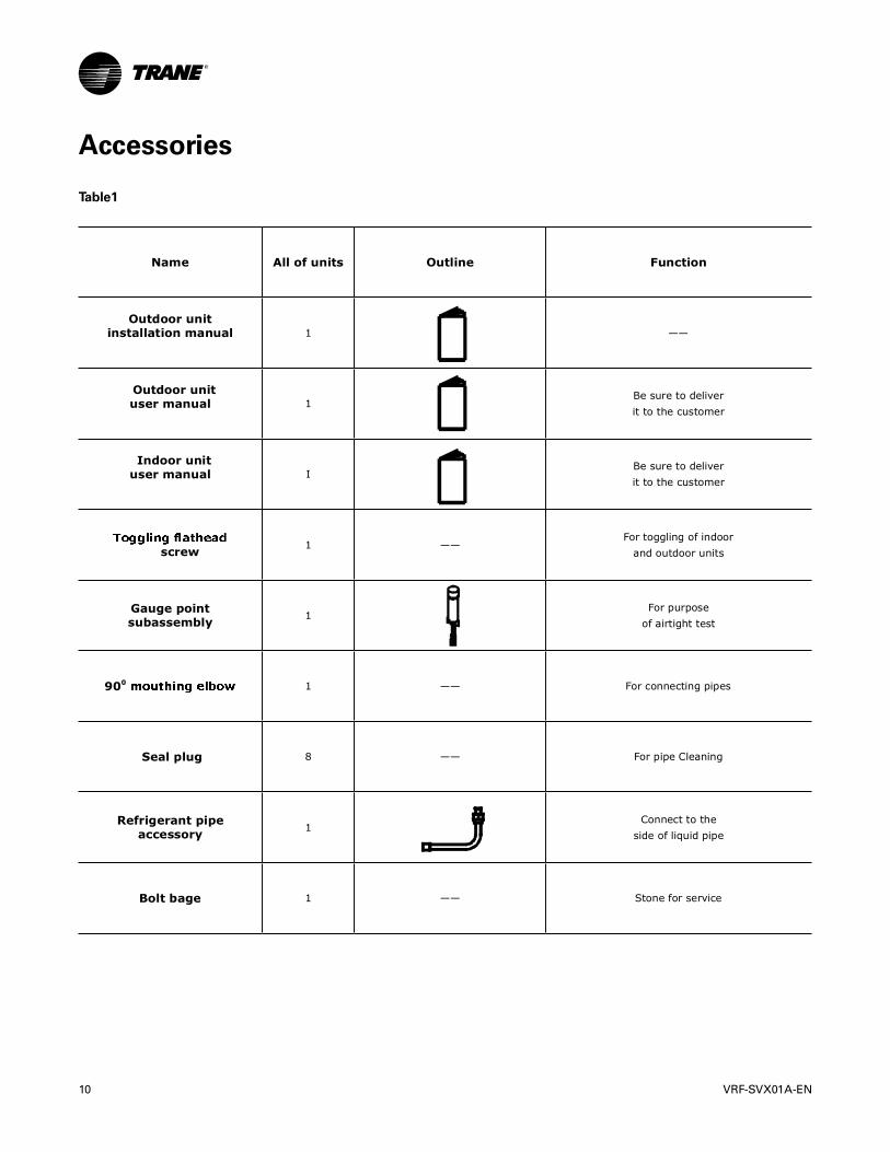
Name All of units Outline Function
Outdoor unitinstallation manual 1 ——
Outdoor unituser manual 1
Be sure to deliverit to the customer
Indoor unituser manual I
Be sure to deliverit to the customer
screw 1 ——For toggling of indoor
and outdoor units
Gauge pointsubassembly 1
For purposeof airtight test
900 1 —— For connecting pipes
Seal plug 8 —— For pipe Cleaning
Refrigerant pipeaccessory 1
Connect to theside of liquid pipe
Bolt bage 1 —— Stone for service

HP Mode Model Max. Connectable Indoor Unit
8 8HP x 1 4TVH0086AD 13
10 10HP x 1 4TVH0096AD 16
12 12HP x 1 4TVH0115AD 16
14 14HP x 1 4TVH0135AD 16
16 16HP x 1 4TVH0155AD 20
18 8HP + 10HP4TVH0182AD
(4TVH0086AD + 4TVH0096AD)20
20 10HP x 24TVH0192AD
(4TVH0096AD x 2)24
22 10HP + 12HP4TVH0211AD
(4TVH0096AD + 4TVH0115AD)24
24 10HP + 14HP4TVH0231AD
(4TVH0096AD + 4TVH0135AD)28
26 10HP + 16HP4TVH0251AD
(4TVH0096AD + 4TVH0155AD)28
28 14HP x 24TVH0270AD
(4TVH0135AD x 2)28
30 14HP + 16HP4TVH0290AD
(4TVH0135AD + 4TVH0155AD)32
32 16HP x 24TVH0310AD
(4TVH0155AD x 2)32
34 10HP x 2 + 14HP4TVH0327AD
(4TVH0096AD x 2 + 4TVH0135AD)36

HP Mode Model Max. Connectable Indoor Unit
36 10HP x 2 + 16HP4TVH0347AD
(4TVH0096AD x 2 + 4TVH0155AD)36
38 10HP + 12HP + 16HP4TVH0366AD
(4TVH0096AD + 4TVH0115AD + 4TVH0155AD)36
40 10HP + 14HP + 16HP4TVH0386AD
(4TVH0096AD + 4TVH0135AD + 4TVH0155AD)42
42 14HP x 34TVH0405AD
(4TVH0135AD x 3)42
44 14HP x 2 + 16HP4TVH0425AD
(4TVH0135AD x 2 + 4TVH0155AD)42
46 14HP + 16HP x 24TVH0445AD
(4TVH0135AD + 4TVH0155AD x 2)48
48 16HP x 34TVH0465AD
(4TVH0155AD x 3)48
50 8HP + 10HP + 16HP x 24TVH0492AD
(4TVH0086AD + 4TVH0096AD + 4TVH0155AD x 2)54
52 10HP x 2 + 16HP x 24TVH0502AD
(4TVH0096AD x 2 + 4TVH0155AD x 2)54
54 10HP + 12HP + 16HP x 24TVH0521AD
(4TVH0096AD + 4TVH0115AD + 4TVH0155AD x 2)54
56 10HP + 14HP + 16HP x 24TVH0541AD
(4TVH0096AD + 4TVH0135AD + 4TVH0155AD x 2)58
58 14HP x 3 + 16HP4TVH0560AD
(4TVH0135AD x 3 + 4TVH0155AD)58
60 14HP x 2 + 16HP x 24TVH0580AD
(4TVH0135AD x 2 + 4TVH0155AD x 2)58
62 14HP + 16HP x 34TVH0600AD
(4TVH0135AD + 4TVH0155AD x 3)64
64 16HP x 4 4TVH0620AD(4TVH0155AD x 4) 64
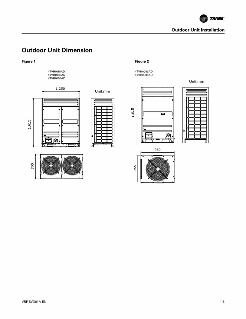
1,250
960
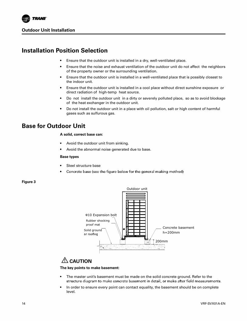
Outdoor unit
10 Expansion bolt
Rubber shockingproof mat
Solid ground Concrete basementh=200mm
200mm
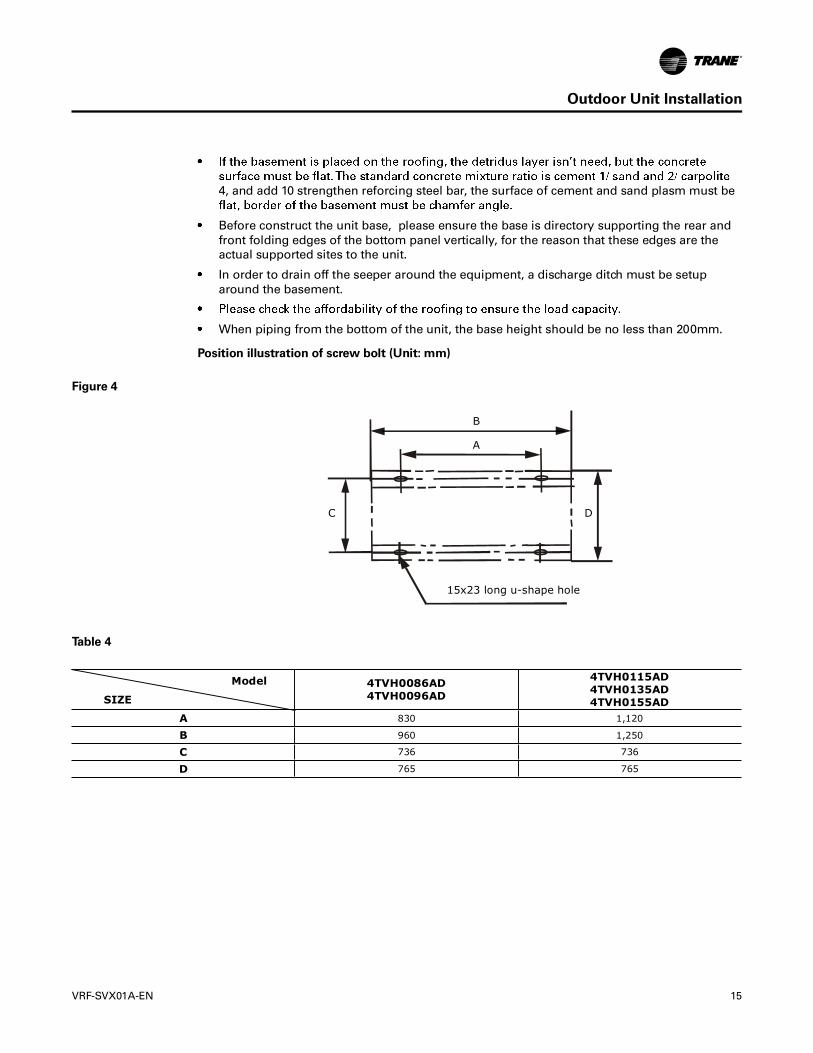
4TVH0086AD4TVH0096AD
4TVH0115AD4TVH0135AD4TVH0155AD
A 830 1,120
B 960 1,250
C 736 736
D 765 765
15x23 long u-shape hole
B
A
C D
Model
SIZE
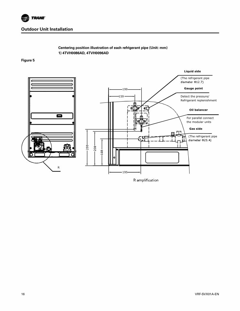
R
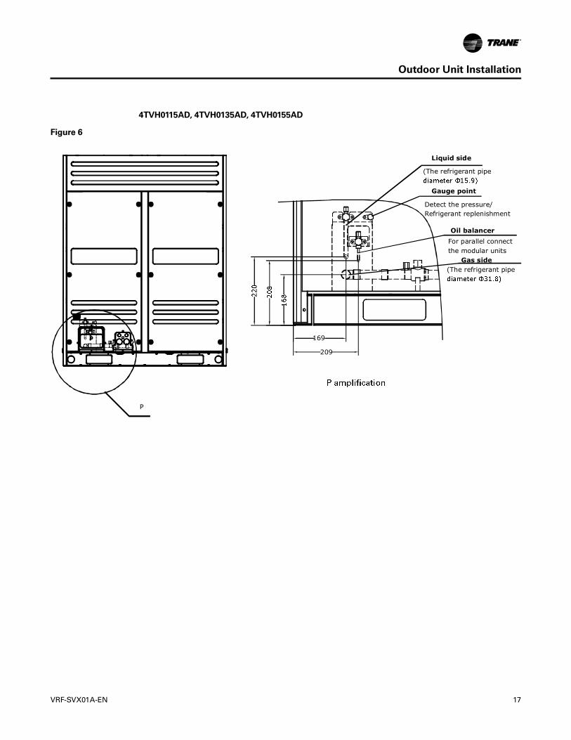
Liquid side
(The refrigerant pipe
Detect the pressure/ Refrigerant replenishment
For parallel connect the modular units
(The refrigerant pipe
Gauge point
Oil balancer
Gas side
199
195
159
Liquid side
(The refrigerant pipe
Detect the pressure/ Refrigerant replenishment
For parallel connect the modular units
(The refrigerant pipe
Gauge point
Oil balancer
Gas side
169
209
P
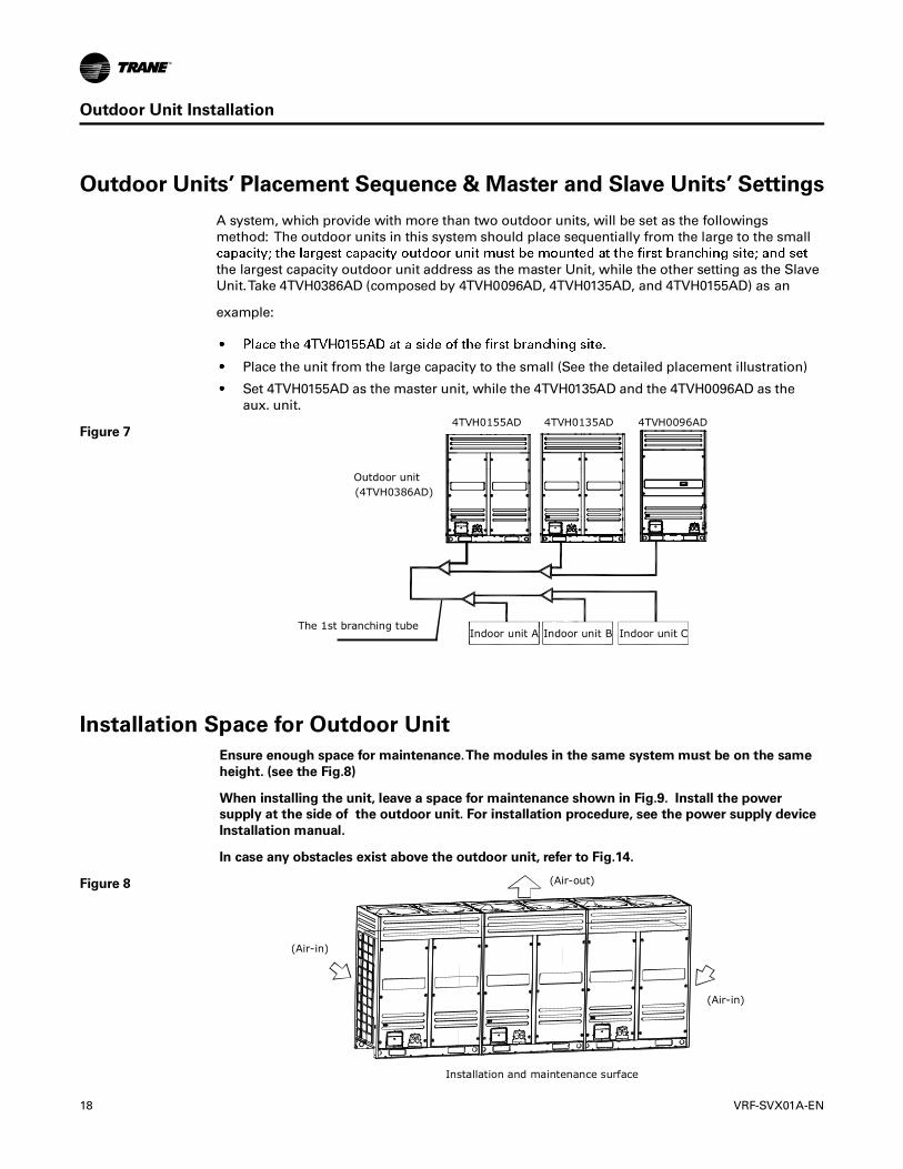
4TVH0155AD 4TVH0135AD 4TVH0096AD
Outdoor unit (4TVH0386AD)
Indoor unit AThe 1st branching tube
Installation and maintenance surface
(Air-in)
(Air-in)
(Air-out)
Indoor unit B Indoor unit C

Top view of the outdoor unit
100mm~500mm 100mm~500mm
>1m>1m>1m
>1m
Front100~500mm
>1m
Front
Front100~500mm
>1m
Front Front
Front
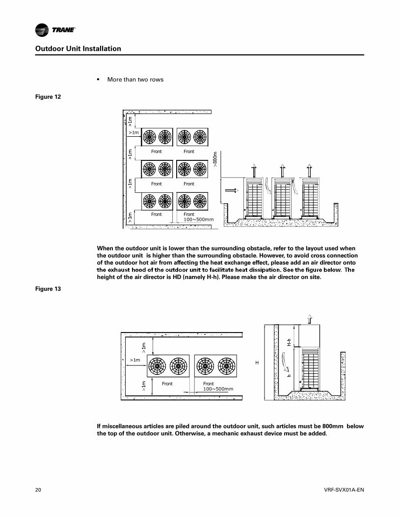
Front100~500mm
>1m
Front
Front
Front Front
Front
Front100~500mm
>1m H
Front

A
A A
B
Side viewFront view
Front view Front view
B B
C
D
A >45° B >300mm
Snow shed for air inlet
Snow shed for air inlet
Snow shed for air outlet

1 4
5
2
3
installation)
Oil balancer
Connect the gas pipe
Gauge point

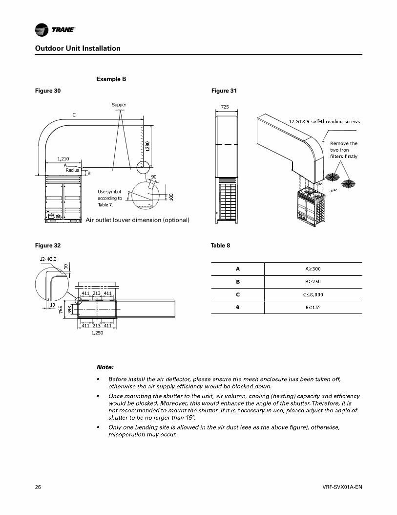
CSupport
A
Radius
B
D
90725
920
A
B
C
D
243
243
243
10
243
330
330
960

920
90
C
B
Supper
ARadius
725
243 243330
960
45
40
35
30
25
20
15
10
5
0
Air volume (m3/h)
A
B
C

1,210
C
Support
90
A
Radius
B
D
0
725
Remove the iron
A
B
C
D
411
411
411
411
213
213
1,250
45
40
35
30
25
20
15
10
5
0
Air volume (m3/h)
1,210
90
Use symbol according to
C
B
Supper
ARadius
725
Remove the two iron
411
411
411
411
213
2131,250
A
B
C

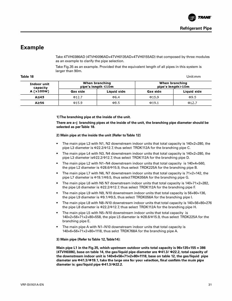
Permitted value Piping
Total actual piping length +a+b+c+d+e+f+j+h+i+j
Actual piping length
Equivalent piping length
——
——
——
L1 L2 B
EF
G
I
C
a
c
e
i jh
f
b
d
N1
Indoor unit
N2
D

Pipe name
Main pipe L1
Indoor unit main pipe
Indoor unit aux. pipe
Outdoor unit refrigerant pipe
Mode Available branching
pipeA<166
G1 L1
L2
W2 W1
E F
I
G
B
C
D
a
c
e f
h i j
b
d
M L
N1
N2

Model
When the equivalent length of all liquid
Available branching pipe
Model
When the equivalent length of all liquid
Available branching pipe

Model
Outdoor
Outdoor Outdoor unit refrigerant pipe diameter
Parallel connect with the branching Main pipe
G2G1
G1
L
M
N M L
L
Indoor unit When branching When branching

G1 L1
L2
W2 W1
E F
I
G
B
C
D
a
c
e f
h i j
b
d
M L
N1
N2

Refrigerant to be Added per meter


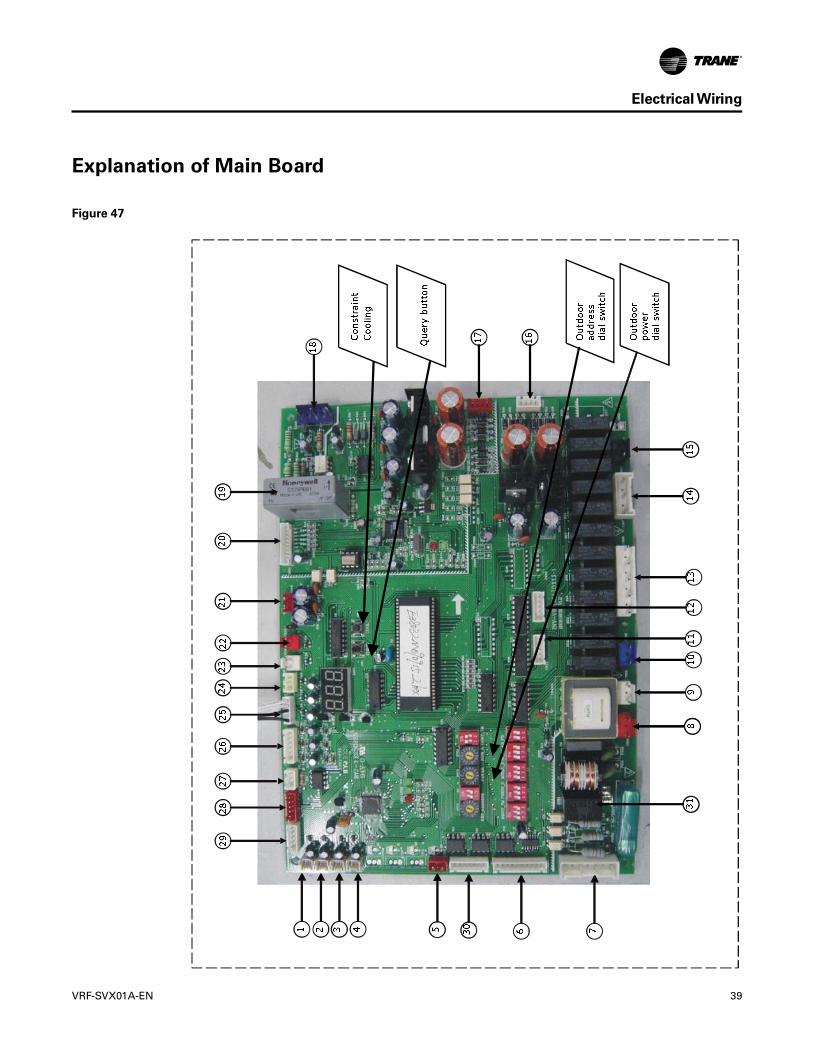
No Display content (Normal display) Note
1 Outdoor unit address 0, 1, 2, 3
2 Outdoor unit capacity 86, 96, 115, 135, 155
3 Modular outdoor unit qty. Available for master unit
4 Outdoor unit total capacity Capacity requirement
5 Indoor unit total capacity requirement Available for master unit
6 The correct total capacity of master unit Available for master unit
7 Operation mode 0, 1, 2, 3, 4
8 The actual operation capacity of this outdoor unit Capacity requirement
9 Fan status 0, 1, 2, 3, 4, 5, 6, 7, 8, 9
10 T2B/T2 average temp. Actual value
11 T3 pipe temp. Actual value
12 T4 ambient temp Actual value
13 Inverter air discharge temp. Actual value
14 Fixed frequency 1 air discharge temp. Actual value
15 Fixed frequency 2 air discharge temp. Actual value
16 Inverter current Actual value
17 Fixed frequency 1 current Actual value
18 Fixed frequency 2 current Actual value
19 TXV opening angle Actual value×8
20 Air discharge pressure Actual value×0.1MPa
21 The limitation of Indoor unit proformed mode 0, 1, 2, 3, 4
22 Indoor unit qty Actual value
23 The last time error or protective code Without protection or error displays as 00
24 —— Spot inspection end

To 380-415V 3N~ 50Hz/60Hz
Outdoor unitscentralized monitoring
Networkaccounting
Indoor unitscentralized control
Indoor unitscommunication
Outdoor unitscommunication
A
K1 K2 E O A E X Y E P Q E H1 H2 E
B C N
K1
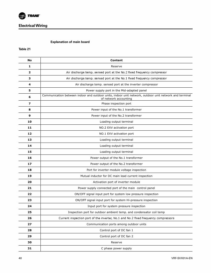
No Content
1 Reserve
2
3
4 Air discharge temp. sensed port at the inverter compressor
5 Power supply port in the Mid-adapted panel
6 Communication between indoor and outdoor units, indoor unit network, outdoor unit network and terminal of network accounting
7 Phase inspection port
8 Power input of the No.1 transformer
9 Power input of the No.2 transformer
10 Loading output terminal
11 NO.2 EXV activation port
12 NO.1 EXV activation port
13 Loading output terminal
14 Loading output terminal
15 Loading output terminal
16 Power output of the No.1 transformer
17 Power output of the No.2 transformer
18 Port for inverter module voltage inspection
19 Mutual inductor for DC main lead current inspection
20 Activation port of inverter module
21 Power supply connected port of the main control panel
22 ON/OFF signal input port for system low pressure inspection
23 ON/OFF signal input port for system Hi-pressure inspection
24 Input port for system pressure inspection
25 Inspection port for outdoor ambient temp. and condensator coil temp
26
27 Communication ports among outdoor units
28 Control port of DC fan 1
29 Control port of DC fan 2
30 Reserve
31 C phase power supply
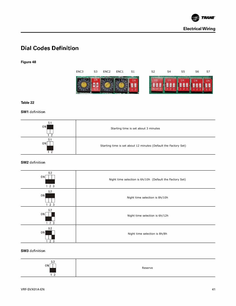
Starting time is set about 3 minutes
Starting time is set about 12 minutes (Default the Factory Set)
Night time selection is 6h/10h (Default the Factory Set)
Night time selection is 8h/10h
Night time selection is 6h/12h
Night time selection is 8h/8h
Reserve
ENC3 S3 ENC2 ENC1 S1 S2 S4 S5 S6 S7
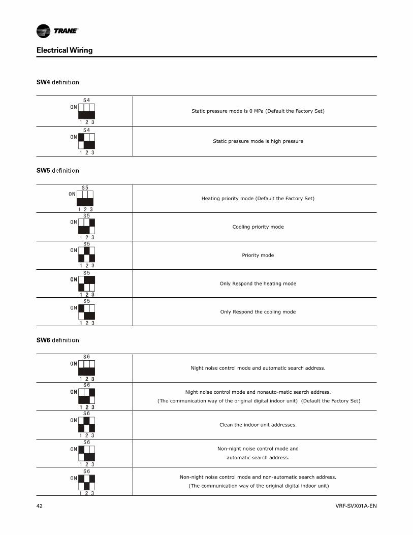
Static pressure mode is 0 MPa (Default the Factory Set)
Static pressure mode is high pressure
Heating priority mode (Default the Factory Set)
Cooling priority mode
Priority mode
Only Respond the heating mode
Only Respond the cooling mode
Night noise control mode and automatic search address.
Night noise control mode and nonauto-matic search address.
(The communication way of the original digital indoor unit) (Default the Factory Set)
Clean the indoor unit addresses.
Non-night noise control mode and
automatic search address.
Non-night noise control mode and non-automatic search address.
(The communication way of the original digital indoor unit)

Reserve
Powersupply
Min.Power wire diameter (mm2) Wiring of mental and synthetic
resinManual switch (A)
Leakage protector Size
(Continuous length of pipe m) Grounding wire Capacity Fuse
4TVH0086AD4TVH0096AD4TVH0115AD
380-415V3N~50Hz
60Hz
4x10mm2(<20)4x16mm2(<50) 1x10mm2 30 25
100mA 0.1 sec or less
4TVH0135AD4TVH0155AD
4x16mm2(<20)4x25mm2(<50) 1x16mm2 40 35
ltem
Model

Outdoor unitscentralized monitoring
LeakageprotectorManualswitch
LeakageprotectorManualswitch
Leakage protector
Branch box
Branch box
Power facilities 1
Power facilities 2
(with leakage protector)
(with leakage protector)
(a)
(a)
(b)
Manual switch
Outdoor unit GND
GND
GND
GND
GND
GND
GND
GND
GND
GND
Outdoor unit
Outdoor unit
Outdoor unit
Outdoor unit
Outdoor unit
Outdoor unit
Outdoor unit
Outdoor unit
Outdoor unit
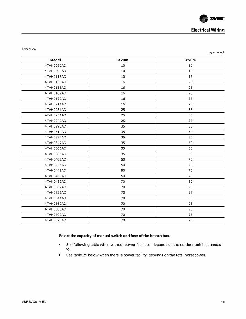
Model <20m <50m
4TVH0086AD 10 16
4TVH0096AD 10 16
4TVH0115AD 10 16
4TVH0135AD 16 25
4TVH0155AD 16 25
4TVH0182AD 16 25
4TVH0192AD 16 25
4TVH0211AD 16 25
4TVH0231AD 25 35
4TVH0251AD 25 35
4TVH0270AD 25 35
4TVH0290AD 35 50
4TVH0310AD 35 50
4TVH0327AD 35 50
4TVH0347AD 35 50
4TVH0366AD 35 50
4TVH0386AD 35 50
4TVH0405AD 50 70
4TVH0425AD 50 70
4TVH0445AD 50 70
4TVH0465AD 50 70
4TVH0492AD 70 95
4TVH0502AD 70 95
4TVH0521AD 70 95
4TVH0541AD 70 95
4TVH0560AD 70 95
4TVH0580AD 70 95
4TVH0600AD 70 95
4TVH0620AD 70 95
Unit: mm2

Model Manual switch (A) Fuse (A)
4TVH0086 - 4TVH0115 32 25
4TVH0135 - 4TVH0155 40 35
4TVH0182 - 4TVH0211 63 50
4TVH0231 - 4TVH0270 80 63
4TVH0290 - 4TVH0327 80 70
4TVH0347 - 4TVH0386 100 80
4TVH0405 - 4TVH0465 125 100
4TVH0492 - 4TVH0541 150 125
4TVH0560 - 4TVH0620 200 150
Indoor power
Leakage protector
Manual switch Branch box
Indoor unit

Outdoor unit(master unit) (Slave unit) (Slave unit) (Slave unit)
(H1 H2 E)
group control
(open)
(H1 H2 E)
(P Q E)
(P Q E)
(H1 H2 E) (H1 H2 E)
Outdoor unit
Signal wire between outdoor units
(All shield terminals of shield wires connect to COMM terminal )
To closed end of shield wire
Signal wire of indoor/outdoor units
Outdoor unit Outdoor unit
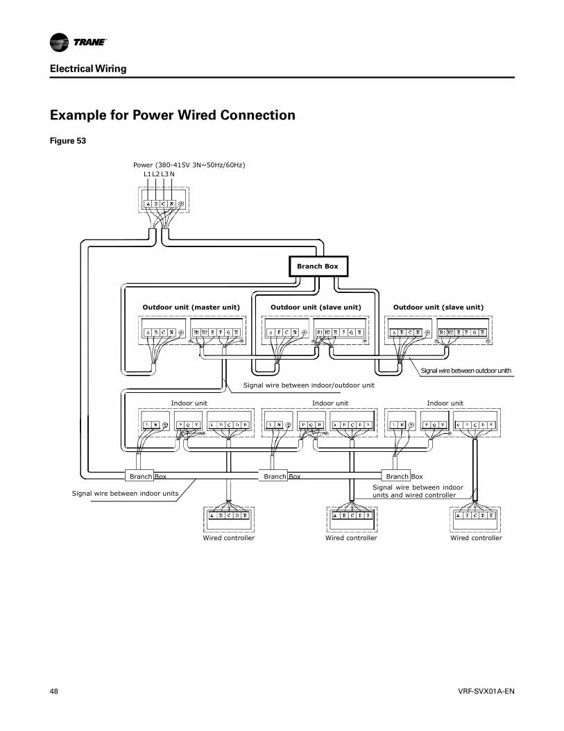
Power (380-415V 3N~50Hz/60Hz) L1L2 L3 N
Branch Box
Branch BoxBranch BoxBranch Box
Outdoor unit (master unit)
Indoor unit Indoor unit Indoor unit
Signal wire between indoor/outdoor unit
Signal wire between indoor unitsSignal wire between indoor units and wired controller
Wired controller Wired controller Wired controller
Signal wire between outdoor unith
Outdoor unit (slave unit) Outdoor unit (slave unit)

Model(indoor unit)
Room NameEg: Indoor unit (A) of the
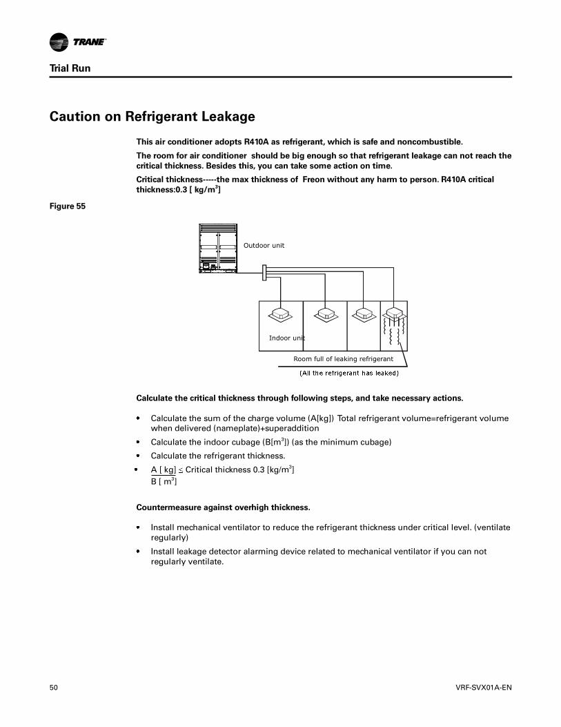
Outdoor unit
Room full of leaking refrigerant
Indoor unit

OA
