~ ~ ~1~q,~ui - cea...- page 3 - 4.3 director (sp&pa), cea stated that power from vindhyachal-iv...
TRANSCRIPT

~ ~ ~ I Government of India ~ I
~ ~ I Ministry of Power
~ ~ ~~~ / Central Electricity Authority ~ I~ ~ ~ Y~~I\1J'11 ~fiJjOf ~ ~
System Planning & Projt::ct Appraisal Division ~-~:~~
~~31R.~.~, ~~-110066Sewa Bhawan, R. K. Puram, New Delhi-ll0066 [ISO: 9001:2008]
~ I Website: www.cea.nic.inNo. 26/10/2013-SP&PA/5$""'1-5"1 ~ Date: 26th September, 2013
1 The Member (PS), 8 Chief Engineer (Trans),Central Electricity Authority, Nuclear Power Corp. of India Ltd.,Sewa Bhawan, R. K. Puram, 9S30, VS Bhavan, Anushakti Nagar,New Delhi-110066 Mumbai-400094
Fax 022-25993570
2 The Member Secretary, 9 The Executive Director (Engg.), ~Western Regional Power Committee, NTPC Lld., Engg. Office Complex,MIDC Area, Marol, Andheri East, Mumbai A-8, Sector-24 , NOIDA 201301Fax 022 28370193 Fax 0120-2410201/2410211
3 The Director (Projects ), 10 The Chief Engineer,Power Grid Corp. of India Ltd., Electricity Department,"Saudamini", Plot No.2, Sector-29, The Government of Goa, PanajiGurgaon-122001 Fax 0832 2222354Fax 0124-2571760/2571932 ...
4 Chairman and Managing Director, 11 ; Executive Engineer (Projects)
MPPTCL, Shakti Bhawan, UT of Dadra & Nagar Haveli,Rampur, Jabalpur-482008 Department of Electricity, SilvassaFax 0761 2664141 Ph. 0260-2642338/2230771
5 The Managing Director, 12 Executive Engineer
CSPTCL, Dangania, Administration of Daman & Diu (U.T.)Raipur (CG)-492013 Department of ElectricityFax 07712574246/4066566 Moti Daman-396220
Ph. 0260-2250889, 2254745
6 The Managing Director, 13 GM, WRLDCGETCO, Sardar Patel Vidyut Bhawan, Plot no F-3, MIDC Area, Msarol,Race Course, Baroda-390007 Andheri(East) Mumbai-400093Fax 0265-2338164 Fax no 022-28235434
7. Director (Operation), 14 CEO,POSOCO
MAHATRANSCO, 'Prakashgad', Plot B-9, Qutab Institutinal Area, Katwaria SaraiNo.G-9, Bandra-East, Mumbai-400051 New Delhi-110016Fax 022-26390383/26595258 Fax 011-26852747
Sub: 36th meeting of the Standing Committee on Power System Planning in Western Region
Sir,The minutes of the 36th meeting of the Standing Committee on Power System Planning in
Western Region held on 29th August 2013 at NRPC, Katwaria Sarai, New Delhi is available on CEAwebsite (www.cea.nic,i[J at the following link: Home page-Wing Specific Document-Power Systems-Standing Committee on Power System Planning-Western Region).
Yours fa~t~fu~ -
t-. "f-J~k :)(K. K Arya )
Chief Engineer (J/C)~
~~
"i~'~'Ci-:':,~'T'.'C'-~...,
" "
~~~ ~ ~1~q,~UI
UUIJ(;fr ~ ~ ~ ~ ~ I \J1 ~ I ~fq)"f ~~ 'IJq';J, ~1f1!~I'J~~:3J ~ 11006~
"cp-o ~o: 26/10/2013-~. m. l1'. ~/5"5"9-5""7~ ~: 26.09.2013
1 ~(fQqff~). 8 ~~~.~ ~ ~. t ~ ~ qll~41~~11 3ff!fi ~ ~.~ ~. 31R cfi 1j'{1f. 9~30. ~ ~. ~ ~,~ ~-110066 ~-40~094 ~~, 022-25993570
2 ~ n. 9 qlllf41('!qI ~ (3t~).m1ft~~'flf1Ifff, \T"Jf.~.~. ~a)"J{. -~~~~~.m. ~ ~. ~-400094 ~\ift~<I~'I" 3frfq;'ff qll~~~. ~-8. ~-24.~~. 022-28370193 ~-201301 ~~. 0124-2410201
3 ~ ~ftm\iRt). 10 ~~. '
~ qll~YI~~113ff!fi ~ ~o.~ ~.lJTCfT~. 'qUj\ift~. ~ ~o 2. ~-29. ~-122001 ~ ~, 0832-2222354~~. 0124-2571760
4 ~aT ~ ~ ~. 11 qlllf41('!(fi ~ (4~<l1\Jf1'~).\T"Jf.1ft.1ft,tT.~:t;['('f. ~~; GTGXT ~ ~ ~ ~ ~ &)if.."'\'rJ!1Ji{. ~-482008 ~ ~. ~.~~, 0761-2664141 ~ ..~ "Io 0260-2642338
I5 ~ ~ 12 qlllf41('!qJ ~.
~~ ~, f&. ~. ~ ~. G1ff ~ & ifitl~II~I1.iri1 ~.G~. ~ ~ifG) -492013 ~ G1ff. ~-396220~ ~.0771-2574246 ~ "Io 0260-2250889, 2254745
6 ~~. .13 qlllf41('!qI~. ~~).\ift.t..~.~;~. ~ ~ ~ ~. ~ 31R ~ ~ ~. ~ --~ 3.~ ~. ~-390007 \T"Jf ~ ~ ~ ~. ~.~ ~. 0265-2338164 ~ ~. ~-400093.
~ m-022-282354347 ~ ~). 14 qlllf41('!qI ~. \{1\{('!J'ot1'l
'1~I~i'<'lqll. IIqll~I'I-S. ~ m-\ift 9. Eft-9, ~ ~~~~~11(,! ~.~-~. ~-400051 qI<::ql~<lI~. ~ ~-110016~ 022-26390383/26595258 ~ 011-26852747
~:- m1ft mcr ~ ~ "lj)\jJ"IT ~ ~ 'flf1Ifff ~ 36~ ~ -~ I~,
m1ft mcr ~ ~ ~'1'\iRT ~ ~ 'flf1Ifff ~ 36~ ~ "(fiT ~ ~ ~ 1I1~q>~UI ~ ~ www.cea.nic.in1f'{ ~ Home page -Power Systems-Standing Committee on Power System Planning-Western Region) ~I' ~ t I
~-~
~~..." -~(~~-~ ~
i;'!i,~:c!1 ("if;. "ifir. 3fri%);(,lc',~:\I! ~ 3i~ (~
.:>
-Page 1-
Minutes of the 36th Meeting of Standing Committee on Power System Planning in Western Region held on Thursday 29th August 2013 at NRPC , New Delhi 1.0 The 36th meeting of the Standing Committee on Power System Planning of Western
Region was held on Thursday 29th August, 2013 at NRPC Katwaria Sarai, New Delhi. The list of participants is enclosed at Annex – I.
2.0 Confirmation of the minutes of 35th meeting of the Standing Committee on
Power System Planning in Western Region (SCPSPWR) held on 3rd January 2013 at M.P Hall, Power Grid Township Sector-43, Gurgaon.
2.1 Director (SP&PA), CEA stated that the minutes of the 35th SCPSPWR were issued
vide CEA letter No.26/10/2013-SP&PA/74-87 dated 4th February 2013. Subsequently, POWERGRID had requested for modification in item no. 17.10 of the minutes and a corrigendum was issued on 5th March, 2013. He requested for confirmation of the minutes of the meeting along with corrigendum.
2.2 The minutes of the meeting along with corrigendum were confirmed by the
committee. 3.0 Review of Progress on Earlier Agreed Transmission Schemes. 3.1 The status of ongoing schemes in Western Region as furnished by POWERGRID is
enclosed at Annexure-II. The status of transmission schemes being implemented through tariff based competitive bidding is enclosed at Annexure- III.
3.2 Status of LILO of one circuit of 400 kV D/C Mundra UMPP – Chorania line at Halvad (GETCO) substation, as an interim arrangement: The LILO of one circuit of 400 kV D/C Mundra UMPP – Chorania line at Halvad (GETCO) substation was agreed as an interim arrangement till the planned network from Halvad sub-station was completed in the 34th SCM, in order to provide operation flexibility. In the 36th SCM, GETCO had informed that the interim arrangement along with the Halvad 400 kV substation is planned to be commissioned by February 2014.
3.3 LILO of 400 kV S/c line between Raipur (PG) and Khedamera (Bhilai) at Raipur
(Raita) 400kV substation and provision of 2X50 MVAR switchable line reactors at Raita end. In the 34th standing committee meeting, interalia, provision of 2x50 MVAR switchable line reactors at Raipur (Raita) end of Raipur (Raita)-Jagdalpur 400 kV D/C line was agreed instead of 1x125 MVAR bus reactor at Raipur (Raita). In the 36th SCM, CSPTCL had informed that they were not implementing the agreed LILO arrangement.
3.4 Status of 10 nos. of bus reactors agreed in the 33rd SCM of WR: In the 36th SCM
POWERGRID had informed that the order for six no. 1x125 MVAr bus reactors has already placed and these rectors are scheduled to be commissioned by Jabalpur – March 2014, Khandwa- January 2014, Shujalpur- May 2014, Bhatapara-May 2014, Raigarh- March 2014 and Aurangabad- June 2014. GETCO had informed that the 1x125 MVAr bus reactors at Ranchodpura (08.07.2013), Versana (25.07.2013), Amreli (12.07.2013) and Rajkot (05.08.2013) has already been commissioned.
3.5 Status of 17 nos. of bus reactors agreed in the 34th SCM of WR: In the 36th SCM MSETCL informed that 1x125 MVAr bus reactors at Nanded, Solapur, Kolhapur and Akola would be commissioned by December 2014.

- Page 2 -
GETCO informed that 63 MVAR bus reactor at Jetpur (11.07.2013) and 125 MVAR
bus reactor at Limbdi (26.07.2013) has already been commissioned. The 125 MVAR bus reactor at Zerda would be commissioned by December 2013.
MPPTCL informed that 80 MVAR bus reactors at Bhopal would be commissioned by
March, 2014. The 1x125 MVAr bus reactor at Nagda, would be commissioned by September 2014 by replacing one of the existing 2x50 MVAr bus reactor at Nagda substation.
POWERGRID informed that the 1X125 MVAR bus reactors at Bachau, Pirana, Itarsi,
Seoni, Parli, Raipur and Gwalior would be commissioned by December 2014 and 1X125 MVAR bus reactors at Damoh would be commissioned by April 2014.
4.0 Contingency arrangement for Rihand–III and Vindhyachal–IV projects of NTPC. 4.1 Director (SP&PA), CEA stated that following transmission system associated with
Vindhyachal-IV and Rihand-III was agreed in the 29th and 32nd SCM of WR:
(i) Rihand-III – Vindhyachal Pooling Station 765kV 2xS/C (initially operated at 400kV)
(ii) Vindhyachal-IV – Vindhyachal Pooling Station 400kV D/c (Quad) (iii) Vindhyachal Pooling Station–Satna 765kV 2xS/c (initially to be
operated at 400kV) (iv) Satna – Gwalior 765kV 2xS/c (v) Sasan – Vindhyachal Pooling Station 765kV S/c (vi) Sasan – Vindhyachal Pooling Station 400kV D/c (vii) Establishment of 765/400kV 2x1500MVA S/s at Vindhyachal Pooling
Station (viii) Gwalior – Jaipur 765/400 kV S/c.
4.2 He said that due to non availability of associated transmission system in the matching time frame of Vindhyachal-IV generation project, an interim arrangement was agreed based on deliberations held in the 32nd, 33rd and 35th SCM of WR. The interim arrangement was required as Vindhyachal -pooling substation was getting delayed due to land acquisition problems and to facilitate the evacuation of power from Vindhyachal–IV and Sasan UMPP generation projects.
a. Completion of Vindhyachal IV- Sasan 400kV D/c (bypassing at Vindhyachal Pooling Station).
b. Interconnection of Vindhyachal-IV STPP 400 kV bus with the existing Vindhyachal-III STPP (by NTPC) along with 1x125 MVAR bus reactor at Bina.
c. Completion of Sasan - Satna 765kV 2XS/c lines along with 1000 MVA 765/400 kV ICT at Sasan.
d. Completion of Satna – Bina 765kV S/c.
e. Completion of 765kV Bina - Gwalior S/c.
f. Installation of 765/400kV transformers each at Bina and Gwalior S/s

- Page 3 -
4.3 Director (SP&PA), CEA stated that power from Vindhyachal-IV is presently being evacuated through the above interim arrangement. Further with second unit of Rihand-III expected by December 2013 and delay in implementation of the 765/400 kV Vindhyachal pooling station, POWERGRID has proposed the following interim arrangement till the completion of 765/400 kV, 2X 1500 MVA Vindhyachal PS:
� Bunching of both circuits of Rihand III - Vindhyachal Pooling station line and
interconnection with one circuit of Vindhyachal PS – Sasan 400 kV D/C line by bypassing Vindhyachal PS.
� Bunching of both circuits of Vindhyachal IV - Vindhyachal Pooling station
400 kV D/C (quad) line and interconnection with another circuit of Vindhyachal PS – Sasan 400 kV D/C line by bypassing Vindhyachal PS.
� Bunching of both circuits of Vindhyachal PS – Satna 765 kV 2XS/C lines and
interconnection with Sasan–Vindhyachal PS 765 kV S/C line through bypassing Vindhyachal PS.
� Bus sectionalizers between Rihand-III and existing stages at Rihand and
between Vindhyachal-IV and existing stages at Vindhyachal are to be kept open.
� The 400 kV line section between Vindhyachal and Sasan (of LILO one circuit
of Vindhyachal – Jabalpur 400 kV D/C line at Sasan) shall be kept open. Further, the transformation capacity at Sasan 765/400 kV switchyard shall be 2X1000 MVA, for full evacuation of power from Rihand-III & Vindhyachal-IV STPP.
4.4 Director (SP&PA), CEA informed that to facilitate the evacuation of power from
Rihand-III and Vindhyachal-IV, in principle approval of the above interim arrangement was given to POWERGRID by CEA in June 2013 with following observations:
� Generation from Vindhyachal-IV or Rihand –III is evacuated over 400 kV S/C lines up to Sasan. In case of outage of the 400 kV S/C line, the entire generation of 1000 MW from Vindhyachal-IV or Rihand –III stage would be lost.
� For full evacuation of 2000 MW power from Rihand-III and Vindhyachal-IV, 2X1000 MVA, 765/400 kV transformation capacity at Sasan is required. In case outage of any 1000 MVA ICT at Sasan, there would be overloading of other ICT. To avoid overloading generation back down at Rihand-III / Vindhyachal-IV would be required.
NTPC has requested for the review of the interim arrangement proposed by POWERGRID and has suggested options for improving the reliability of evacuation of power.
4.5 DGM POWERGRID informed in the meeting that land at Vindhyachal Pool was available and Vindhyachal Pool S/S would be commissioned with in a year. Therefore, the interim arrangement would be required for one year. Based on the request from NTPC, interim arrangement as above has been reviewed and the following modified interim arrangement is proposed :
- Page 4 -
� Interconnection of one circuit of Rihand III - Vindhyachal Pooling station line with one circuit of Vindhyachal PS – Sasan 400 kV D/C line bypassing Vindhyachal PS.
� Interconnection of one circuit of Vindhyachal IV - Vindhyachal Pooling station
400 kV D/C (quad) line with another circuit of Vindhyachal PS – Sasan 400 kV D/C line bypassing Vindhyachal PS.
� Interconnection of the other circuits of Rihand III - Vindhyachal Pooling station
line and Vindhyachal IV - Vindhyachal Pooling station line so as to form interconnection between Rihand-III and Vindhyachal-IV.
� Bunching of both circuits of Vindhyachal PS – Satna 765 kV 2XS/C lines and
interconnection with Sasan–Vindhyachal PS 765 kV S/C line through bypassing Vindhyachal PS.
� Bus sectionalizers between Rihand-III and existing stages at Rihand are to be
kept open. � The 400 kV line section between Vindhyachal and Sasan (of LILO one circuit
of Vindhyachal – Jabalpur 400 kV D/C line at Sasan) shall be kept open. Further, the transformation capacity at Sasan 765/400 kV switchyard shall be 2X1000 MVA, for full evacuation of power from Rihand-III & Vindhyachal-IV STPP.
4.6 NTPC agreed with the modified interim arrangement proposed. NTPC further requested that in case of any contingency in the above interim arrangement, if required, one unit of Rihand-III shall be connected to existing stages of Rihand.
4.7 Members concurred with the above interim arrangement till the availability of Vindhyachal 765/400 kV pooling station.
4.8 Members also agreed that in case of commissioning of Rihand-III unit-2 before implementation of above interim arrangement, the generation of unit-2 of Rihand-III shall be evacuated through existing Vindhyachal generation bus through HVDC back to back depending on the available system margins as agreed in the 31st SCM of NR.
5.0 Termination of 400 kV D/C (2nd) line from Khandwa to Rajgarh at Indore in
place of Rajgarh. 5.1 Director (SP&PA), CEA said that the transmission system associated with Mauda-II
generation project of NTPC was agreed in the 31st and 32nd SCM and consist of the following:
(i) Mauda-II – Betul 400 kV D/C (quad) line.
(ii) Betul – Khandwa 400 kV D/C (quad) line.
(iii) Khandwa – Rajgarh 400 kV D/c line.
(iv) Establishment of 2X315 MVA, 400/220 kV Betul (GIS) substation.

- Page 5 -
5.2 He said that the area in which Rajgarh substation is located has been notified as Bird Sanctuary by Madhya Pradesh Government. The Khandwa – Rajgarh 400 kV D/C (2nd) line, will pass through the Bird Sanctuary and there would be delay in completion of the transmission system. Mauda-II generation project is scheduled for commissioning by December 2015. Due to anticipated delay in implementation of Khandwa – Rajgarh 400 kV D/C (2nd) line, POWERGRID has proposed termination of the Khandwa – Rajgarh 400 kV D/C (2nd) line at Indore (PG) 400 kV substation instead of at Rajgarh. Based on the request from POWERGRID, CEA has given in principle approval of revised transmission system from Mauda-II generation project of NTPC, as given below, in April 2013 to enable POWERGRID to go ahead with the tendering activities for the revised system.
(i) Mauda-II – Betul 400 kV D/C (quad) line.
(ii) Betul – Khandwa 400 kV D/C (quad) line.
(iii) Khandwa – Indore (PG) 400 kV D/c line.
(iv) Establishment of 2X315 MVA, 400/220 kV Betul (GIS) substation.
5.3 GM, WRLDC suggested that the interconnection of Betul sub-station with WR grid
either by LILO of Koradi-Satpura 400 kV line at Betul or by connecting Betul with Seoni through a 400 kV line.
5.4 After further discussion, revised system from Mauda-II as indicated above was agreed. It was also decided that interconnection of Betul with other grid point would be studied separately.
6.0 Review of transmission system associated with Solapur STPP 1320 MW (2X660 MW) of NTPC.
6.1 Director (SP&PA), CEA said that following transmission system associated with
Solapur STPP (2X660 MW) generation project of NTPC was agreed in the 30th SCM:
(i) Solapur NTPC- Solapur (PG) 400kV D/c line.
(ii) Solapur NTPC - Pune (PG) 400kV (Quad) D/c line.
(iii) Augmentation of 400/220kV ICT by 1x315 MVA transformer at Solapur (PG).
6.2 He said that when the transmission system was planned a no. of gas based generation projects were envisaged in SR and it was anticipated that SR would export power to WR and NR. The envisaged generation in SR is not happening and SR is facing huge power deficit. In view of the changed generation scenario, the transmission system from Solapur STPP was reviewed and is given below:
(i) Solapur NTPC- Solapur (PG) 400kV D/c (Quad) line.
(ii) Solapur NTPC - Pune (PG) 400kV (Quad) D/c line (deferred as of now, and shall be taken up as and when required in future).
(iii) Augmentation of 400/220kV ICT by 1x315 MVA transformer at Solapur (PG). (by shifting 3rd transformer from Wardha to Solapur)
- Page 6 -
6.3 He added that in-principle approval for the modifications in the transmission system associated with Solapur STPP was given to POWERGRID in April 2013 so that they can go ahead with the tendering activities for the revised system. Further, NTPC has requested to provide additional 400 kV D/C outlet from Solapur STPP in order to utilize the 2 no. Pune line bays either through LILO of any existing line or 2nd outlet to Solapur (PG).
6.4 MSETCL stated that 3rd ICT at Solapur is not required. CTU informed as decided in the 35th SCM, the 3rd ICT at Solapur (PG) is being shifted from Wardha (PG).
6.5 After further discussions, members agreed with the following transmission system from Solapur STPP for which in principle approval has been given by CEA to POWERGRID in April 2013 to expedite its implementation.
(i) Solapur NTPC- Solapur (PG) 400kV D/c (Quad) line.
(ii) Solapur NTPC - Pune (PG) 400kV (Quad) D/c line (deferred as of now, and shall be taken up as and when required in future).
(iii) Augmentation of 400/220kV ICT by 1x315 MVA transformer at Solapur (PG). (by shifting 3rd transformer from Wardha to Solapur).
6.6 With regard to 2nd 400 kV outlet from Solapur STPP the following transmission system was agreed as Solapur STPP-Part A:
a) Solapur NTPC- Solapur (PG) 400kV D/c (Quad) 2nd line in lieu of Solapur NTPC - Pune (PG) 400kV (Quad) D/c line agreed earlier with Solapur STPP.
7.0 Approval for conversion of Line reactors into Bus reactors at Kasor (GETCO)
as an interim arrangement.
7.1 Director (SP&PA), CEA stated that Kasor (GETCO) 400 kV substation is experiencing high voltage during light load conditions. The 400 kV line bays and line reactors (2x50MVAR) at Kasor end of Kasor-Rajgarh 400kV D/c line has been charged and are out of service. Kasor-Rajgarh 400kV D/c line is being implemented by M/s Reliance Power Transmission Ltd., and is not yet ready because of forest clearance issues. In order to contain high voltage at Kasor sub-station, POWERGRID has proposed utilizing the Line bays and Line reactors associated with Kasor-Rajgarh 400 kV D/c line as Bus reactor bays and Bus reactors at Kasor (GETCO) substation till the availability of Kasor-Rajgarh 400 kV D/c line as an interim arrangement.
7.2 He said that CEA has given in principle approval for the proposal of POWERGRID for conversion of Line reactors and Line bays into Bus reactor and Bus reactor bay at Kasor (GETCO) substation to contain the over voltages as an interim arrangement till the availability of Kasor-Rajgarh 400 kV D/c line.
7.3 Members agreed with the proposal.

- Page 7 -
8.0 Commissioning of 1X240 MVAR, 765 kV Bus reactor and 1500 MVA, 765/400 kV transformer at Raigarh pooling station (Kotra).
8.1 Director (SP&PA), CEA stated that during light load conditions, the voltage at Raigarh (existing) substation is in the range 430 kV-435 kV. POWERGRID has intimated that one 240 MVAR bus reactor along with 1X1500 MVA, 765/400 kV ICT at Raigarh (Kotra) pooling station and the 400 kV D/c line between Raigarh pooling station and Raigarh (existing) was ready and has requested for in principle approval of CEA for charging of 240 MVA bus reactor at Raigarh (Kotra) through the 765/400 kV, 1500 MVA ICT and the Raigarh (Kotra) – Raigarh (existing) 400 kV D/C line to control over voltage.
8.2 He added that in principle approval was given to POWERGRID for commissioning of 1X240 MVAR, 765 kV Bus reactor and 1500 MVA, 765/400 kV transformer at Raigarh pooling station (Kotra) as it will help in containing the over voltage at Raigarh (existing).
8.3 POSOCO informed that the 240 MVAR bus reactor, 765/400 kV ICT and 400 kV line has already been commissioned and a voltage relief of about 10 kV is observed during light load conditions at Raigarh (existing) 400 kV substation.
8.4 Members agreed with the proposal.
9.0 System Strengthening Scheme in WR for transfer of power to SR
9.1 Director (SP&PA), CEA stated that second circuit of Solapur-Pune 765 kV S/C line was agreed in the 30th SCM of WR as a part of transmission system strengthening with in WR and NR for transfer of power from IPP generation projects in Southern Region to target beneficiaries in WR and NR. Subsequently, in the 35th SCM of WR the above line was agreed to be taken up as WR-NR system strengthening scheme due to slow progress of generation projects in SR and grant of LTA to IPPs in WR with target beneficiaries in NR. Further, Kolhapur-Padghe 765 kV D/C one ckt via Pune was agreed as a part of transmission system associated with new IPP generation projects in Nagapattinam / Cuddalore in the 31st SCM of WR. Due to non-availability of most of the envisaged generation in Southern Region, huge power deficit is being faced by Southern Region states and the inter-regional links between Southern Region and Western Region i.e. Solapur – Raichur 765kV 2xS/c and Wardha – Hyderabad 765kV D/c lines would be used to export power of IPPs in Chhattisgarh to Southern Region.
9.2 He added that system studies carried out by POWERGRID, corresponding to 2016-17 condition, considering revised load generation scenario indicate loading on Wardha – Hyderabad 765kV D/c line to the tune of 3500 MW and loading on Solapur – Raichur 765kV 2xS/c line is about 750 MW. Under outage of one ckt. of Wardha – Hyderabad 765kV line, the loading on the other ckt is about 2900 MW and power flow on Raichur – Solapur lines increases to 1100 MW. To balance the loading between these two corridors from WR to SR (Wardha-Hyderabad and Raichur–Solapur) Aurangabad–Solapur 765kV D/c line has been considered. It is observed that the loading on Wardha – Hyderabad is about 2500 MW and loading on Solapur – Raichur is about 1500 MW. The loading under contingency of Wardha – Hyderabad 765kV one circuit reduces to 2400MW.
9.3 He said that in principle approval was given to POWERGRID to implement
Aurangabad- Solapur 765kV D/c line in lieu of Solapur-Pune 765 kV S/c (2nd ckt) and
LILO of one ckt of Aurangabad-Padghe 765 kV D/C line at Pune in lieu of Kolhapur-

- Page 8 -
Padghe 765 kV D/C one ckt via Pune in May 2013, as system strengthening scheme
in WR for transfer of power to SR from IPPs in Chhattisgarh.
9.4 MD, GETCO stated that we are planning/constructing many 765 kV transmission lines where reactive power management is an issue, while many countries have restricted their transmission voltage to 500 kV.
9.5 MSETCL stated that at present the planning studies are done on MW basis whereas
here is need for reactive planning studies on all India basis in view of extensive development of 765 kV network. He requested to include the cost of the schemes and its incremental impact on the tariff.
9.6 SE, WRPC emphasized upon the need of having a reactive power policy. He
suggested that for controlling high voltage, reactive compensation may be planned for demand reduction up to 70% of the peak demand and opening of lines may be considered to control over voltage for reduction of demand below 70%.
9.7 COO, CTU stated that construction of new lines is getting difficult day by day
because of severe RoW issues. The 765 kV lines are being planned keeping emerging load generation scenario and electricity market development in view. He added that reactive compensation is planned based on the off peak conditions. Further while granting connectivity / LTA, generation developer are asked to provide bus reactor(s) at their generation switchyard. Also line reactors are planned on the 765 kV lines to provide 100 % reactive compensation. Regarding the cost of the schemes, the same would be indicated in the proposals.
9.8 After deliberations, members agreed with the proposal.
10.0 Transmission system associated with Mundra UMPP (5X800 MW). 10.1 Director (SP&PA), CEA stated that the generation specific transmission system
associated with Mundra UMPP consists of the following elements which has already been commissioned:
(i) Mundra UMPP – Bachau - Ranchodpura 400 kV D/C (triple snowbird) line. (ii) Mundra UMPP – Limbdi 400 kV D/C (triple snowbird) line. (iii) Mundra UMPP – Jetpur 400 kV D/C (triple snowbird) line.
10.2 He said that revised Transmission Planning Criteria, 2013 specifies review of existing / already planned transmission scheme to be N-1-1 compliant. The criteria specifies that subsequent to the outage of a 400 kV S/C line, the system shall be able to survive a permanent single phase to ground fault on a 400 kV line close to the bus. Accordingly, system studies have been carried out to review the existing transmission system associated with Mundra UMPP. The system studies have been carried out considering full dispatch from generation projects in Mundra complex and under the contingency of outage of Mundra UMPP – Bachau 400 kV D/C line, the angular separation of 36 degree between Mundra and Limbdi is observed. To overcome this, POWERGRID has proposed the following transmission system strengthening as an immediate measure in the transmission system associated with Mundra UMPP generation project:
- Page 9 -
a) LILO of both circuits of Mundra UMPP – Limbdi 400 kV D/C (triple snowbird) at Bachau.
b) LILO of one circuit of under construction Bachau – Varsana 400 kV D/C line at
Mundra UMPP (the LILO portion shall be with triple snowbird conductor).
10.3 He said that CEA has given in principle in June 2013 for the above transmission system strengthening proposed for Mundra UMPP.
10.4 Members agreed with the proposed system strengthening for Mundra UMPP.
11.0 Interim arrangement around Indore and Vadodara. 11.1 Director (SP&PA), CEA stated that in the 35th SCM, interconnection of Vadodara-
Asoj 400 kV D/C line and Vadodara-Pirana 400 kV D/C line by bypassing Vadodara S/S so as to form Pirana-Asoj 400 kV D/C line was agreed as a contingency arrangement till the availability of Vadodara S/S. MPPTCL has requested POWERGRID for providing two number bays at Indore (PG) 400 kV substation for termination of the Pithampur – Indore (PG) 400 kV D/c line. POWERGRID has informed that there is delay in implementation of 2 nos. of bays at Indore (PG) and Vadodara 765/400 kV sub-station is also getting delayed due to land acquisition problems.
11.2 He said that POWERGRID has informed that Indore (PG)-Vadodara 765 kV S/C line, Vadodara-Pirana 400 kV D/C (Quad) line and Vadodara-Asoj 400 kV D/C (Quad) line approved as a part of IPP projects in MP and Chhattisgarh (HCPTC-IV & V) are expected to be commissioned by October 2013. In order to transfer power from the IPPs in MP and Chhattisgarh to Gujarat and provide connectivity to Pithampur (MPPTCL) 400 kV sub-station, POWERGRID has proposed following interim arrangement till the availability of 765/400 kV Vadodara S/S.
a) Opening of 1st ckt of Indore (MPPTCL)-Indore (PG) 400 kV D/C line at Indore (PG) end and connecting it with Indore (PG)-Vadodara 765 kV S/C line by bypassing Indore (PG) S/S.
b) Connecting Vadodara end of the above Indore (MPPTCL)-Vadodara line to one circuit of Vadodara-Asoj 400 kV D/C line by bypassing Vadodara S/S so as to form Indore (MPPTCL)-Asoj 400 kV S/C line.
c) Bunching of Vadodara-Pirana 400 kV D/C line and connecting it with other circuit of Vadodara-Asoj (GETCO) 400 kV line by bypassing Vadodara S/S
d) LILO of 2nd ckt of Indore (MPPTCL)-Indore (PG) 400 kV D/C line at Pithampur (MPPTCL) (till the availability of two 400 kV bays at Indore (PG)).
The interim arrangement proposed would result in following configuration:
i) Indore (MPPTCL)-Asoj 400 kV S/C line by bypassing Indore (PG) and Vadodara sub-stations. The length of the line would be around 380 km and for charging of the above line POWERGRID has informed that following reactive compensation would be available:
a) 125 MVAR bus reactor at Indore (MPPTCCL)

- Page 10 -
b) 240 MVAR line reactor (at 765 kV) charged at 400 kV at Indore (PG)
c) 50 MVAR bus reactor at Asoj (GETCO)
ii) Asoj-Pirana 400 kV S/C line by bypassing Vadodara sub-stations
iii) Indore (MPPTCL)-Pithampur (MPPTCL) 400 kV S/C line
iv) Indore (PG)-Pithampur (MPPTCL) 400 kV S/C line
A diagram showing the interim arrangement is given below:
11.3 On a query from GETCO regarding time frame in which Vadodara 765/400 kV S/S would be commissioned and about charging of Indore-Asoj 380 km long line, DGM, POWERGRID informed that land for Vadodara S/S is available and is expected to be commissioned by December 2015. The reactors available at Indore (MPPTCL), Indore (PG) and Asoj would be used for charging the line.
11.4 On a query from MPPTCL regarding availability of 2 no. 400 kV bays at Indore (PG), DGM POWRGRID informed that the bays would be available by January 2014.
11.5 MD, GETCO requested for provision of 2x500 MVA 400/220 kV transformation capacity at Vadodara sub-station to meet their load demand at Vadodara.
11.6 After further discussion, Members agreed with the interim arrangement till the availability of 400 kV bays at Indore (PG) and Vadodara 765/400 kV sub-station. Members also agreed with the request of GETCO to provide 2x500 MVA 400/220 kV at Vadodara with 4 no. 220 kV bays.
12.0 Proposal for modification in existing network arrangement for smooth
evacuation of power from Sardar Sarovar Power (SSP) project - agenda by GETCO.
12.1 Director (SP&PA), CEA stated that the associated transmission system of SSP (1450 MW) is as given below:
- Page 11 -
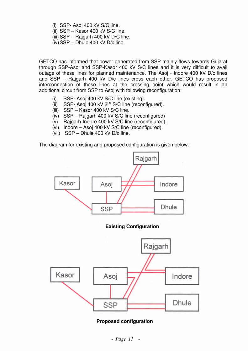
(i) SSP- Asoj 400 kV S/C line. (ii) SSP – Kasor 400 kV S/C line. (iii) SSP – Rajgarh 400 kV D/C line. (iv) SSP – Dhule 400 kV D/c line.
GETCO has informed that power generated from SSP mainly flows towards Gujarat through SSP-Asoj and SSP-Kasor 400 kV S/C lines and it is very difficult to avail outage of these lines for planned maintenance. The Asoj - Indore 400 kV D/c lines and SSP – Rajgarh 400 kV D/c lines cross each other. GETCO has proposed interconnection of these lines at the crossing point which would result in an additional circuit from SSP to Asoj with following reconfiguration:
(i) SSP- Asoj 400 kV S/C line (existing). (ii) SSP- Asoj 400 kV 2nd S/C line (reconfigured). (iii) SSP – Kasor 400 kV S/C line. (iv) SSP – Rajgarh 400 kV S/C line (reconfigured) (v) Rajgarh-Indore 400 kV S/C line (reconfigured). (vi) Indore – Asoj 400 kV S/C line (reconfigured). (vii) SSP – Dhule 400 kV D/c line.
The diagram for existing and proposed configuration is given below:
Existing Configuration
Proposed configuration
- Page 12 -
12.2 He said that the length of the existing line between SSP and Asoj is 83 km whereas the length of the second interconnection after reconfiguration would be about 340 km and unequal power flow on these lines. Further, the interim arrangement proposed by POWERGRID around Vadodara provides two nos. of additional in feeds to Asoj. The system studies carried out with interim arrangement and with about 1200 MW dispatch at SSP, indicates normal power flows even in case of outage of SSP- Asoj or SSP – Kasor 400 kV S/C line.
12.3 WRLDC informed that if both the lines from SSP to Dhule are available, about 400 MW flows towards Dhule, because of high voltage problem at SSP, one circuit of SSP-Dhule has to be kept open. Providing reactor at Dhule to contain over voltage could solve the problem.
12.4 MS, WRPC informed that Narmada Control Authority (NCA) has requested for providing line reactors at Rajgarh and Dhule. The issue has also been deliberated in the PSC of NCA and OCCM of WRLDC wherein installation of reactors at Raigarh and Dhule has been agreed. Further, NCA has requested WRPC to take up the matter in Standing Committee meeting on Power System Planning in WR. He opined that the providing 63 MVAR line reactors (switchable) at Dhule and Rajgarh end of the SSP-Dhule 400 kV D/C line and SSP- Rajgarh 400 kV D/C line respectively would help in containing over voltage at Sardar Sarovar
12.5 After further discussion, Members agreed with provision of 2X63 MVAR (switchable) line reactors at Dhule and Rajgarh end each in 400 kV lines from SSP. The existing network configuration from SSP would continue. In case of difficulty in taking outage of SSP- Asoj or SSP – Kasor 400 kV S/C line, necessary arrangements may be made in the generation switchyard so that more power is evacuated through SSP-Dhule and SSP- Rajgarh 400 kV D/C line.
13.0 Proposal for modification in existing network arrangement for smooth
operation of power system in South Gujarat- agenda by GETCO
13.1 Director (SP&PA), CEA stated that GETCO has intimated that generation from coastal coal based power projects (Mundra UMPP, Mundra Adani, Essar Vadinar) has increased while generation from gas based power projects in south Gujarat (TPGL, GSEG, Kawas, Gandhar etc.) has been reduced considerably due to high cost / non-availability of gas. This has caused overloading in the 220 kV network in South of Gujarat. The lines viz., Jhanor – Haldarwa 220 kV D/C line, Kawas- Ichchapore 220 kV D/C line, Kosamba – Kim 220 kV S/C line, Ukai – Mota 220 kV D/c line etc. are operating at thermal rating. To avoid overloading GETCO has suggested the following modification in the existing 400 kV network as an interim arrangement till availability of Kosamba-Vapi 400 kV D/C line :
(i) Inter connection of one circuit of Ukai– Kosamba 400 kV D/c line of GETCO with Jhanor – Navsari (Dastan) 400 kV D/C line of POWERGRID at the point of intersection, so as to form Ukai – Navsari 400 kV S/C line and Jhanor – Kosamba 400 kV S/C line.
(ii) LILO of Jhagadia - Haldarwa 220 kV S/c line at Jhanor TPS. This would help in control loading of Jhanor-Haldarwa 220 kV D/C line.
The exhibits showing existing and proposed arrangement are given below:

- Page 13 -
13.2 GM, WRLDC stated that high loading of 220 kV network would be controlled with provision of an additional ICT at Kosamba. After, the proposed reconfiguration there would be 400 kV S/C between Jhanor TPS to Navsari (Dastan).
13.3 MD, GETCO stated that reconfiguration of the existing network has been proposed after carrying out detailed studies. By making this interconnection arrangement, there would be direct connectivity of 400 KV Kosamba (GETCO) substation with Jhanor TPS and Navsari (Dastan-PG) substation with Ukai TPS. This will greatly helps in evacuation of power from new 500 MW unit at Ukai TPS. Also, it will result in operational flexibilities in South Gujarat area. In near future, after commissioning of 400 KV D/C Chorania (Limdi) - Kosamba line, 400 KV Kosamba substation will receive power from UMPP Mundra. The 2nd ICT at Kosamba would be implemented with in a month and at present to control overloading on 220 kV lines bus splitting arrangement at Kosamba and opening of 400/220 kV ICT at Ukai is being practiced.
13.4 NTPC stated that no space was available in the present switchyard. However, for two no. 220 kV bays for LILO of Jhagadia - Haldarwa 220 kV S/c line at Jhanor TPS, extension of the 220 kV bus would be required. Space for extension of the switchyard was available.

- Page 14 -
13.5 After further discussion, LILO of Jhagadia - Haldarwa 220 kV S/c line at Jhanor TPS by GETCO was agreed. Members also agreed the interconnection of Jhanor - Navsari 400 kV line and Ukai – Kosamba 400 kV line as an interim arrangement and the same would be reviewed when the present 400 kV interconnection between Navsari-Vapi (an interim arrangement) would be removed or in case of any grid restrictions.
14.0 Interim arrangement for 765/400kV Champa Pooling Substation under High
Capacity Corridor – V for IPPs in Chhattisgarh.
14.1 Director (SP&PA), CEA stated that 765/400 kV Champa Pooling station has been planned along with Champa Pool – Raigarh Pool (Kotra) 765kV S/c line, Champa Pool – Raipur Pool 765kV D/c line and Champa Pool – Dharamjaygarh/Korba 765kV S/c line. POWERGRID had informed that these lines shall be ready progressively from October, 2013 to December, 2013 and there is delay in implementation of 765/400kV Champa Pooling substation due to land acquisition problem. To evacuate power from IPPs being pooled at Champa pooling station POWERGRID has proposed the following interim arrangement:
(i) Interconnection of Raigarh Pool (Kotra) - Champa Pool 765kV S/c with Champa Pool – Dharamjaygarh 765kV S/c line bypassing Champa Pool.
(ii) Out of the KSK Mahanadi - Champa Pool 400 kV 2xD/c line, one 400 kV D/c line
shall be terminated to LILO of one circuit of Raigarh – Raipur 400 kV D/c line (as per existing arrangement). The other 400 kV D/c from KSK Mahanadi to Champa shall be extended to Raipur (Existing) by connecting this to Champa Pool – Raipur Pool 765 D/c line (charged at 400 kV & bunching and interconnecting this line with one circuit Raipur Pool – Raipur (existing) 400 kV D/c line). This arrangement shall make KSK Mahanadi – Champa Pool (Champa Pool bypassed) – Raipur Pool (bunching of 765 kV D/c line and bypassing Raipur Pool 765 kV bus) – Raipur (existing) line charged at 400 kV. Also the other circuit of Raipur Pool – Raipur (existing) 400 kV D/c line shall remain with existing arrangement connected to 765/400 kV ICTs at Raipur Pool.
14.2 COO, CTU informed that the interim arrangement was proposed due to delay in implementation of 765/400 kV Champa pooling station due to land acquisition issues. The land for the Champa pooling station has been acquired and the interim arrangement proposed above is not required at present. The interim arrangement, if required, would be revised based on the progress of line bays and lines terminating at Champa pooling station.
14.3 Members noted the same. 15.0 MPPTCL Proposal of Installation of Line shunt reactors on Nagda-Indira Sagar
and Indira Sagar-Satpura 400kV Lines at 400kV S/s at Nagda, Indira Sagar HEP and Satpura TPS end.
15.1 Director (SP&PA), CEA stated that MPPTCL has intimated that Madhya Pradesh is
experiencing very high voltage during the off peak condition and to control over voltages many of the 400 and 220kV lines are to be kept open in the State. Indira Sagar-Nagda 400kV line being main evacuation line from Indira Sagar HEP has to
- Page 15 -
be tripped due to over voltage. Further, the power corridor from Satpura TPS and Indira Sagar HEP to load centers of Western MP is passing through 400kV bus of Indira Sagar HEP and tripping of 400kV ISP-Nagda and 400kV ISP-Satpura lines because of high voltage isolates the loads of Western MP from the generation at Indira Sagar and Satpura. This situation shall become more critical after addition of generating capacity at Satpura TPS. The normal voltage observed at Indira Sagar is in the range of 420-430 kV. At present there is no reactive compensation (line / bus) provided at Indira Sagar. The matter of tripping of lines due to over voltages has been raised and discussed at different platforms between MPPTCL, ISP and WRPC.
15.2 He added that for controlling over voltage, MPPTCL has proposed to install
following reactors:
(i) 125 MVAR, 400kV Bus reactor at Indira Sagar HEP (to be provided by NHDC / NVDA)
(ii) 50 MVAR Line reactor for Indira Sagar-Satpura 400kV S/C line at Satpura 400 kV Substation (to be provided by MPPGCL)
(iii) 50 MVAR Line reactor for Indira Sagar-Nagda 400kV line at Nagda 400kV Substation (to be provided by MPPTCL)
15.3 In order to avoid tripping of Indira Sagar-Nagda and Satpura-Indira Sagar 400 kV
lines due to over voltage, Members agree with the proposal of MPPTCL.
16.0 Additional System Strengthening based on new Transmission Planning Criteria for Mundra UMPP (5x830 MW)
16.1 Director (SP&PA), CEA stated that CEA has given in principle approval to
POWERGRID for following transmission system strengthening for Mundra UMPP
generation project:
a) LILO of both circuits of Mundra UMPP – Limbdi 400 kV D/C (triple snowbird)
at Bachau.
b) LILO of one circuit of under construction Bachau – Versana 400 kV D/C line at Mundra UMPP (the LILO portion shall be with triple snowbird conductor).
16.2 He said that with the establishment of Bhuj pooling station as a part of transmission
system strengthening for renewable energy sources in Gujarat, LILO section of item
b above would be terminated at Bhuj pooling station, thus forming Mundra-Bhuj 400
kV D/C line and the Bachau – Versana 400 kV D/c line would be restored to its
original configuration. Thus, the additional transmission system strengthening has
been proposed for Mundra UMPP, to comply with ‘N-1-1’ criteria of the new
Transmission Planning Criteria and is given below:
i) LILO of both circuits of Mundra UMPP – Limbdi 400 kV D/c (triple snowbird)
at Bachau.
ii) Mundra UMPP – Bhuj Pooling station 400 kV D/c line (triple snowbird)
.

- Page 16 -
16.3 He said that with the above proposal, the LILO of Mundra UMPP- Limbdi at
Saurashtra Pool agreed in 35th SCM stands deleted. The Load Flow studies
carried out indicate that line loadings and angles are within their limits. Presently,
SPS has been planned with Mundra UMPP to back down generation in the event of
“n-1-1” contingency. To avoid backing down of available generation the scheme
mentioned above needs to be implemented on urgent basis by POWERGRID in
compressed time schedule.
16.4 Members agreed with the proposal to be implemented by POWEGRID in
compressed time schedule.
17.0 Additional transmission system strengthening for Sipat STPS (2x500 + 3x660 MW).
17.1 Director (SP&PA), CEA stated that the immediate evacuation from Sipat STPS
consists of following elements which have been commissioned:
(i) Sipat – Bilaspur Pooling Station 765 kV 2xS/c line
(ii) 2x1000 MVA, 765/400 kV transformers at Sipat STPS.
17.2 He said that in previous SCM, NTPC had requested to provide an additional 765 KV
circuit from Sipat to Bilaspur / any other location to enhance the redundancy in the
evacuation system, as there have been several instances of station outages at Sipat.
In some of the instances, tripping of one of the 765 KV Sipat-Bilaspur Pooling station
line has led to tripping of other 765 KV line. WRPC/RLDC has also recommended
strengthening of transmission system from Sipat with additional 765 KV circuit to
Bilaspur Pooling station. To enhance redundancy in the Sipat evacuation system
POWERGRID has proposed the following additional transmission system
strengthening:
(i) Sipat – Bilaspur Pooling Station 3rd 765 kV S/c line.
(ii) Bilaspur Pooling Station – Dhanwahi pooling station 765 kV D/c line.
(iii) Establishment of new 2X1500, 765/400 kV Dhanwahi Pooling Station.
(iv) LILO of both circuits of Jabalpur - Orai 765 kV D/C at Dhanwahi pooling
station.
(v) LILO of all circuits of Vindhyachal – Jabalpur 400 kV 2xD/c line at
Dhanwahi pooling station.
17.3 COO (CTU), stated that Dhanwahi 765/400 kV pooling station proposed as a part of
the system strengthening, interconnects the Bilaspur pooling station with Jabalpur
(WR) and Orai (NR).
17.4 After deliberations, members agreed with the additional transmission system
strengthening for Sipat STPS.
- Page 17 -
18.0 400 kV interconnection of Gwalior 765/400 kV substation
18.1 Director (SP&PA), CEA stated that Bina – Gwalior 765 lines and Gwalior – Agra 765
lines has been charged at its rated voltage of 765 kV. With this upgradation there is no 400 kV interconnections at Gwalior. Presently the Gwalior substation has transformation capacity of 2x1500 MVA at 765/400 kV level and 3x315 MVA at 400/220 kV level.
18.2 He added that in order to provide 400 kV anchoring at Gwalior, it is proposed to establish a new 400/220 kV substation near Morena and interconnect it with Gwalior through a 400 kV D/c (quad) line. This will improve the reliability of power supply in Gwalior area and also help in effective utilization of 765/400 kV transformers at Gwalior. MPPTCL needs to plan 220 kV outlets for drawal of power from the proposed 400 kV substation at Morena.
18.3 MPPTCL has indicated 220 kV D/C lines to Morena (MP) and Sabaigarh (MP) as
220 kV outlets from proposed Morena sub-station. The same would be firmed up after finalization of location of Morena 400 kV sub-station.
18.4 Members agreed with the proposal.
19.0 Additional Strengthening at Raipur and Raigarh (Tamnar) 765/400 Substations.
19.1 Director (SP&PA), CEA stated that at present is only 1x1500 MVA, 765/400 transformer at Raipur 765/400 kV pooling station and to improve the reliability of this substation, it is proposed to augment the transformation capacity by 1x1500 MVA, 765/400 kV transformer. Further, Raigarh (Tamnar) pooling station is connected to Raigarh (Kotra) through 765 kV D/c line and to improve the reliability of power transfer from generating stations connecting at Raigarh (Tamnar) substation, it is proposed to LILO both circuits of Jharsuguda – Dharamjaigarh 765 kV 1xD/c line at Raigarh (Tamnar), which is passing in close vicinity of Raigarh (Tamnar) 765/400 kV pooling station.
19.2 DGM POWERGRID said that at Raigarh (Tamnar) about 4500 MW generation is getting connected at 400 kV level and only 3 no. 1500 MVA 765/400 kV transformers are there at Raigarh (Tamnar), therefore an additional 4th 1500 MVA 765/400 kV transformer at Raigarh (Tamnar) is proposed.
19.3 After discussion, Members agreed with the following:
a) Augmentation of 2nd 1x1500 765/400 kV transformer at Raipur sub-station b) LILO both circuits of Jharsuguda – Dharamjaigarh 765 kV 1xD/c line at Raigarh
(Tamnar) c) Augmentation of 4th 1x1500 765/400 kV transformer at Raigarh (Tamnar) sub-
station.
20.0 Evacuation of Renewable Energy generations located in WR and NR to Northern Region states.
20.1 GM, POWERGRID stated that POWERGRID has prepared a report on Green Energy Corridors based on the envisaged renewable capacity (42 GW) addition in the 12th Plan period in the 8 number Renewable Energy (RE) rich states. The report covers a comprehensive scheme for strengthening of Intra State as well as Inter-
- Page 18 -
state transmission system and other related infrastructure to address challenges associated with large scale renewable integration. Subsequently, CEA convened a meeting in May 2013 for assessing RES (Renewable Energy Source) capacity additions in the states of Rajasthan, Himachal Pradesh, J&K, Gujarat, Maharashtra, Tamil Nadu, Karnataka and Andhra Pradesh by the end of 12th Plan period. As per the assessment, the quantum of RES generation expected by the end of 12th Plan period is 32 GW and the same is given as under:
(i) Rajasthan - 5694 MW
(ii) Himachal Pradesh - 1281 MW
(iii) J&K - 476 MW
(iv) Gujarat - 4729 MW
(v) Maharashtra - 4063 MW
(vi) Andhra Pradesh - 4827 MW
(vii) Karnataka - 4290 MW
(viii) Tamil Nadu - 7353 MW
20.2 He said that with above quantum of envisaged Renewable capacity addition, it is expected that some of the RE rich state including Gujarat, Rajasthan may have more RE capacity than the capacity required for fulfilling their Renewable Purchase Obligations (RPO). Further, such RE rich host state may also not absorb RE energy locally particularly during the other than peak hour condition. Inherent characteristics of renewables necessitates requirement of adequate balancing generation reserves to take care of Intermittency / variability. Further, the IEGC stipulates, renewable energy plants to have “MUST RUN” status and shall not be subjected to “merit order dispatch” principles.
20.3 He added that Kutch in Gujarat is one of the renewable rich pocket in the country endowed with Wind and Solar Generation potential. In 12th Plan period, Gujarat has envisaged about 900 MW Wind and 180 MW Solar generation capacity additions alone in Kutch area. In addition, applications for Connectivity of 600 MW wind generation capacity in Kutch complex has also been received by the CTU. Likewise, Rajasthan has also envisaged 5694 MW Renewable capacity addition during 12th Plan period, increasing total RE capacity to about 8100 MW. Considering the above, in order to facilitate transfer of RE power from the RE rich potential States to other States as well as absorption of RE power within the RE rich states (host state), transmission system strengthening both at intra state and inter-state level has been identified. Further, in order to identify transmission requirement for transfer of RE power from the RE rich potential States to other States, studies have been carried out for the 2016-17 time frame considering 18th EPS demand for Seasonal Light Load condition (Monsoon off peak) in which renewable is maximized. In such scenario, maximized renewable dispatch scenarios (Wind-70%, Solar-80%) have been considered in other than the peak demand hours (80% of EPS peak demand for WR/SR/ER) for studies. As per the analysis of historical trends of NR demand during monsoon season, demand of Northern region is considered as 95% of the peak demand as the region has a typical flat load profile over the day due to its agricultural load during the monsoon periods when renewable is maximized. In this scenario, special area dispatch i.e. full dispatch from Kutch complex generations viz. Mundra UMPP (4150 MW) as well as Adani Mundra (4620 MW) is considered.
- Page 19 -
20.4 He stated that in view of the envisaged RE capacity addition in Kutch complex in Gujarat and existing/planned capacities of conventional generation, it is proposed that a 765/400kV pooling station near Bhuj may be established. Bhuj pool substation may be interconnected to a pooling station in northern part of Gujarat viz. Banaskantha at 765kV level an upcoming Solar generation hub. This substation is also proposed to be anchored with existing 400kV Sankhari (GETCO) substation, a major Solar Pooling hub. Considering the requirement of onward dispersal of power outside Gujarat to other states, a High capacity transmission corridor is being proposed right from the Gujarat (WR) to Punjab in NR via Rajasthan. Towards this, Banaskantha substation is proposed to be connected to southern/central part of Rajasthan at Chittorgarh and Ajmer in Rajasthan at 765kV level.
20.5 He added that out the capacity addition of 5694 MW in Rajasthan, about 2000 MW is
envisaged near Bhadla (distt. Jodhpur), Jaisalmer belt etc in 12th plan period. With already existing generation and low power demand in the area there is a need for strengthening to transfer power out of the area. RRECL has informed about development of a solar park near Bhadla of about 2000 MW additional capacity in future. Therefore, establishment of 765/400kV substation at Bhadla with Bhadla-Ajmer 765kV D/c and 400kV interconnection to Bhadla and Pokhran (new-RVPN) has been considered. With this interconnections, 765kV Ajmer, a major power pooling point, shall aggregate power from WR/Gujarat through Banaskantha / Chittorgarh as well as Bhadla(Jodhpur) in Rajasthan. There is a need for providing a low impedance corridor for evacuation of power beyond Ajmer, for onward dispersal of above power outside Rajasthan. Therefore a 765kV High capacity transmission corridor is proposed towards Moga in Punjab, a major load centre in NR, via Suratgarh pooling station in Rajasthan over 765kV network. Moga is also connected to Kishenpur in J&K, which is large hydro pocket in Jammu & Kashmir. In this manner, this shall facilitate integration of Renewable with hydro complex, enabling supply side balancing through Hydro resources. Accordingly following inter state transmission system is proposed :
Gujarat (Western Region)
(i) Bhuj Pool – Banaskantha 765kV D/c (ii) Banaskantha – Chittorgarh 765kV D/c (iii) Banaskantha – Sankhari 400kV D/c (iv) Establishment of 765/400 kV, 2x1500 MVA S/s at Bhuj Pool (v) Establishment of 765/400 kV, 2x1500 MVA S/s at Banaskantha. (vi) Associated reactive compensation (Bus reactors & Line reactors)
Rajasthan (Northern region)
(i) Chittorgarh – Ajmer(New) 765kV D/c (ii) Ajmer(New) - Suratgarh(New) 765kV D/c (iii) Suratgarh(New)-Moga(PG) 765kV D/c (iv) Bhadla(New)- Ajmer(New) 765kV D/c (v) Chittorgarh (New)- Chittorgarh (RVPN) 400kV D/c (Quad) (vi) Ajmer (New)- Ajmer (RVPN) 400kV D/c (Quad) (vii) Suratgarh (New)- Suratgarh (existing) 400kV D/c (Quad) (viii) Bhadla (New)- Bhadla (RVPN) 400kV D/c (Quad) (ix) Bhadla (New)- Pokaran (new-RVPN) 400kV D/c (Quad) (x) Establishment of 2x1500 MVA, 765/400kV S/s at Chittorgarh (xi) Establishment of 2x1500 MVA, 765/400kV S/s at Ajmer (New)
- Page 20 -
(xii) Establishment of 765/400 kV (2x1500 MVA) & 400/220 kV (2X500 MVA), S/s at Bhadla (new)
(xiii) Establishment of 2x1500 MVA, 765/400kV S/s at Suratgarh (New). (xiv) Associated reactive compensation (Bus reactors & Line reactors).
20.6 MD, GETCO stated that the renewable generation generally comes up at 220kV
level, therefore 220 kV voltage level needs to be provided at the 765/400kV pooling station being proposed at Bhuj and Banaskanta.
20.7 After discussion, Member (PS), CEA opined that due to urgent requirement of
strengthening for Mundra UMPP/Adani Mundra generation projects as well as short gestation period of Renewable, transmission strengthening may be implemented in a compressed time schedule.
20.8 Members agreed that due to early requirement the following scheme may be
implemented in compressed schedule by POWERGRID: Western Region (Gujarat): i. Bhuj Pool–Banaskantha 765 kV D/c ii. Banaskantha -Chittorgarh 765 kV D/c iii. Banaskantha-Sankhari 400 kV D/c iv. 765/400/220kV (765/400 kV-2x1500 MVA & 400/220kV-2x500MVA) sub-station
each at Bhuj Pool and Banaskantha. v. Associated reactive compensation (Bus reactors & line reactors) Northern Region (Rajasthan): i. Chittorgarh-Ajmer (New) 765 kV D/c ii. Ajmer (New)-Suratgarh (New) 765 kV D/c iii. Suratgarh (New)-Moga (PG) 765 kV D/c iv. Chittorgarh-Chittorgarh (RVPN) 400 kV D/c (Quad) v. Ajmer (New)- Ajmer (RVPN) 400 kV D/c (Quad) vi. Suratgarh (New)- Suratgarh 400 kV D/c (Quad) vii. 2x1500 MVA, 765/400 kV sub-station each at Chittorgarh, Ajmer (New) and
Suratgarh (New) viii. Associated reactive compensation (Bus reactors & line reactors).
20.9 It was also agreed that the renewable generations would be allowed to inject in the ISTS at Bhuj, Banaskantha, Chittorgarh, Ajmer etc., if they apply for LTA quantum which is atleast 25% of their installed capacity.
20.10 The following system was also discussed and approved. However, it was decided
that this system shall taken up for implementation only after receipt of application for Connectivity and LTA for sufficient quantum from Solar/ wind generation developers around Bhadla area:
i. Bhadla (New)-Ajmer (New) 765 kV D/c ii. Bhadla (New)-Bhadla (RVPN) 400 kV D/c (Quad) iii. Bhadla (New)-Pokhran New (RVPN) 400 kV D/c (Quad) iv. 765/400/220kV (765/400 kV-2x1500 MVA & 400/220kV- 2x500MVA) sub-
station at Bhadla (New)
- Page 21 -
20.11 The intra-state transmission system required for integration of RES generation in the states of Gujarat and Maharastra as identified by CEA, CTU & states were also agreed. The details of the above intra-state transmission system are given at Annexure-V for Gujarat and at Annexure – VI for Maharashtra.
21.0 Installation of 125 MVAR Bus reactor at Birsinghpur TPS switchyard by
MPPGCL- Agenda proposed by MPPTCL
21.1 Director (SP&PA), CEA stated that MPPTCL has intimated that the voltage at 400 kV substation of Birsinghpur TPS remains high above 425 kV most of the time and with the outage of 500 MW unit at Birsinghpur TPS the voltage rises above 430 kV. To control the voltage at Birsinghpur 400 kV substation, lines emanating from Birsinghpur are required to be opened. The over voltage issue at Birsinghpur has also been reported by NLDC in their operational feedback.
21.2 He said that to control over voltage at Birsinghpur, MPPTCL has proposed installation of one 125 MVAR bus reactor at Birsinghpur TPS switchyard by MPPGCL.
21.3 Members agreed with the installation of 1x125 MVAR bus reactor at Birsingpur TPS
to be provided by MPPGCL.
22.0 Evacuation of Power from Adani Mundra Generation Project
22.1 COO, CTU stated that M/s Adani Power Limited (APL) has established a 4620MW generation project at Mundra in Kutch dist. Gujarat. From their generation project, M/s Adani Power has tied up 3966 MW of power under long term, the details of which are as given below:
� Gujarat : 2000MW � Maharashtra : 200 MW � Haryana : 1424 MW � LTOA : 342 MW (With Punjab and Rajasthan (NR) as target beneficiaries
without Long Term PPA)
� In addition 200 MW power has been tied up under MTOA.
22.2 He added that for transfer of power to Haryana (PPA for 1424 MW), M/s Adani Power Limited had established Mundra – Mohindergarh ± 500kV HVDC 2500MW Bi-pole & Mohindergarh - Dhanonda 400kV (Quad) D/c lines as dedicated transmission system. Additionally, M/s Adani Power Limited had set up Mohindergarh – Bhiwani (PG) 400kV D/c line for 342 MW LTA to Punjab and/or Rajasthan beyond Mohindergarh considering that 342 MW power would be available at Mohindergarh HVDC terminal. This LTA for 342 MW was approved with point of injection of power as Bhiwani Substation of POWERGRID. M/s Adani Power Ltd. had applied to CERC for grant of transmission license for the dedicated transmission system consisting of Mundra – Sami - Dehgam, Mundra – Mohindergarh HVDC bipole, Mohindergarh – Dhanonda, Mohindergarh – Bhiwani, lines, electrode lines and other associated works. CERC vide its order dated 29/07/2013 has directed that transmission license be granted to Adani Power Limited. M/s Adani Power vide letter dated 21/05/2013 has applied for Long Term Access at their generation switchyard for 342MW. As per the LTA application, point of injection is Adani Generation bus. Now with the grant of license, the Adani bus is to be treated as ISTS bus and accordingly LTA is to be granted from Adani generation bus.

- Page 22 -
22.3 He further informed that as per the CERC order dated 29/07/2013 as per para 11 “as
the subject transmission system developed by the petitioner is already being used as per PPA dated 07/08/2008 for supply of power to UHBVNL & DHBVNL for a quantum of 712 MW each the petitioner shall be deemed to be long term access customer for 1424 MW.” Accordingly, 1424 MW PPA with Haryana is also to be treated as LTA from Adani Mundra generation bus and M/s Adani has to bear the transmission charges and losses for this. Accordingly LTA to M/s Adani Power Limited is deemed to be granted for about 1500 MW (1424 for PPA and losses (exact figure shall be worked out in consultation with NRLDC)) from generation bus from the date of operation of the Adani system as ISTS system and M/s Adani shall bear the transmission charges for the same. In long term perspective, an additional line from Adani Mundra generation bus to Banaskantha / Bhuj pooling station needs to be considered and integrated with the high capacity corridor being planned with RE generation projects in Rajasthan and Gujarat
22.4 After deliberations, the following was agreed by the members:
i. As per CERC order the PPA of Haryana would be from Adani Bus and Adani shall bear the transmission charges & losses for the same. Accordingly, the transfer of power to Haryana shall be from Adani Mundra generation project considering an injection of about 1500 MW (1424 for PPA and losses (exact figure shall be worked out in consultation with NRLDC)) at generation bus. This shall be applicable from the date of operation of Adani transmission system as ISTS system.
ii. LTA of 342 MW to NR from Adani Mundra generation was formalized with injection point as Adani Mundra generation bus in place of Bhiwani and with present SPS in place. SPS scheme shall be reviewed after commissioning of Mundra – Zerda 400 kV D/c line. LTA of 342 MW for NR from Mundra generation bus as well as other power transfer through ISTS i.e. LTA of 200 MW to Maharashtra & MTOA for 200 MW from Adani Mundra generation bus can become effective from the date of operation of the Adani system as ISTS system.
iii. In long term perspective, an additional line from Adani Mundra generation bus to Banaskantha / Bhuj pooling station was agreed.
23.0 Response to POSOCO report on Operational Feedback on Transmission
Constraints
23.1 Director (SP&PA), CEA stated that POSOCO in its report on ‘Operational Feedback on Transmission Constraints - April 2013’ has listed transmission lines and ICTs which are experiencing constraints due to overloading and also the nodes experiencing high voltage. The constraints mentioned in the report are: a) Overloading of Kawas-Ichapore 220 kV line b) Overloading of Sugen – Vapi 400 kV S/C line c) Parli – Lonikhand 400 kV D/C line d) 400 kV D/C lines emanating from Mundra UMPP. e) ICT constraint on 3X315, 400/220 kV ICT at Vapi.

- Page 23 -
f) Nodes experiencing high voltages Raipur, Raigarh, Birsinghpur, Khandwa, Damoh, Bhopal, Nagda, Rajgarh, Bhadrawati, Wardha, Dhule, Kolhapur, Bhusawal, Akola, Solapur, Mapusa, Bhilai, Lonikhand, Parli.
23.2 He said that to control over voltage in Western Region installation of 27 nos. of bus
reactors at various locations in WR has been agreed in the 33rd and 34th SCM of WR. Some reactors have already been commissioned and others are under various stages of implementation. In DNH, Kala 400/220 kV substation has already been planned which would relieve the loading of Vapi ICTs. For Kawas-Ichapore overloading, the LILO of one circuit of Kawas-Vav at Ichapore may be implemented as decided in the 34th SCM of WR. Additional interconnection with Vapi has already been planned to avoid overloading of Sugen-Vapi 400 kV S/C line. With regard to Mundra UMPP, additional system strengthening has also been agreed.
23.3 Members noted the above.
24.0 Additional evacuation line from Vindhyachal-IV & V STPP (3x500 MW)
24.1 Director (SP&PA), CEA stated the immediate evacuation of Vindhyachal-IV & V STPP (VSTPP) consists of Vindhyachal-IV generation switchyard-Vindhyachal Pool 400 kV D/c (Quad) line. NTPC have requested to provide additional outlet from Vindhyachal-IV generation switchyard in order to increase the reliability of the power evacuation system for VSTPP-IV & V project. Further, to meet the “n-1-1” contingency as stipulated in revised planning criteria, following additional transmission system for Vindhyachal-IV & V is proposed:
(i) Vindhyachal-IV & V STPP – Vindhyachal Pool 400 kV D/c (Quad) 2nd line.
24.2 Members agreed with the proposal.
25.0 Termination of Vapi – Navi Mumbai 400kV D/c line at upcoming Kudus substation of MSETCL.
25.1 Director (SP&PA), CEA stated that in the previous meeting termination of Vapi – Navi Mumbai 400 kV D/c line at Kudus substation of MSETCL was agreed due to severe RoW problem. MSETCL have informed POWERGRID in May, 2013 that all bays available at Kudus are earmarked for the lines already sanctioned. There is no space at Kudus for termination of Vapi-Navi Mumbai line. MSETCL has suggested that LILO of only one circuit of Tarapur – Padghe 400 kV D/c may be done at Kudus. This would release two bays, which could be used for termination of Vapi-Navi Mumbai line.
25.2 He added that POWERGRID has informed that due to severe Right-of-Way
constraint in the portion between Kudus and Navi Mumbai, the line portion between Kudus and Navi Mumbai cannot be constructed. Hence, it is proposed to modify Vapi-Navi Mumbai 400kV D/c line under WRSS-V as Vapi-Kudus 400kV D/c line.
25.3 MSETCL stated that it was difficult to implement the 220 kV lines from the Navi
Mumbai 400/220 kV substation due to severe RoW problems. POWERGRID stated LILO of 400 kV Lonikhand/Pune – Kalwa S/C line at Navi- Mumbai 400 kV substation was being implemented by laying of cables near Navi Mumbai and at present cable

- Page 24 -
trench works was in progress. MSETCL can share the cable corridor for laying of the 220 kV lines for evacuating power from Navi Mumbai 400 kV substation.
25.4 After deliberation, Members agreed with the following:
a) LILO of only one circuit of Tarapur-Padghe 400 kV D/C line at Kudus for providing 2 no. bays for termination of Vapi-Navi Mumbai 400 kV D/C line at Kudus.
b) Vapi-Navi Mumbai 400kV D/c line agreed under WRSSS-V modified as Vapi-Kudus 400kV D/c line.
25.5 Members requested MSETCL to take up 220 kV lines for drawal of power from Navi
Mumbai 400/220 kV substation. 25.6 Chairman and Member (PS), CEA enquired about the status of implementation of
two nos. of 400 kV bays at Dhule (MSETCL) 400 kV substation for termination of the 400 kV D/C line from Dhule (IPTC) 765/400 kV substation. MSETCL informed that they have put up the proposal for their board approval. MSETCL enquired about the recovery of the capital cost of two nos. of 400 kV bays at Dhule. Chairman and Member (PS), CEA clarified that the capital cost of the two nos. of 400 kV bays at Dhule (MSETCL) shall be recovered through transmission charges for the bays as a part of national pool for interstate transmission system. MSETCL should implement the two no. of 400 kV bays at Dhule on priority basis as the Dhule(IPTC)-Dhule (MSETCL) 400 kV D/C line was scheduled for commissioning by March 2014.
26.0 Commissioning of 2x25% FSC of Rajgarh – Karamsad (Kasor) 400 kV D/c line.
26.1 Director (SP&PA), CEA stated that Western Region Transmission Gujarat Private Limited (WRTGPL), a subsidiary of Reliance Power Transmission Limited is implementing Rajgarh – Kasor 400 kV D/c line which is held up due to forest clearance issues. This line was planned with 2x25 % fixed series compensation (FSC). POWERGRID has already implemented both line bays as well as FSC at Rajgarh. FSC is available since September 2011 but could not be commissioned due to non-availability of Rajgarh – Kasor 400 kV D/c line. Rajgarh – Kasor 400 kV D/c line is not likely to be commissioned in near future and commissioning of 2x25% FSC is pending since September 2011 and involves contractual issues. POWERGRID has proposed that the FSC may be tested and commissioned by connecting to some other 400 kV line emanating from Rajgarh 400 kV substation as an interim arrangement.
26.2 DGM, POWERGRID informed that FSC is proposed to be connected with Rajgarh-
Nagda 400 kV D/C line. The testing and commissioning of FSC would be completed with in 15 days.
26.3 After deliberation, Members agreed that FSC may be tested and commissioned by connecting it with Rajgarh-Nagda 400 kV D/C line to close the contractual issues. The FSC may be removed from the Rajgarh-Nagda 400 kV D/C line after testing and commissioning.
- Page 25 -
27.0 Additional evacuation line from Sasan UMPP (6x660 MW)
27.1 Director (SP&PA), CEA stated that POSOCO has recently reported multiple outages in the system and has suggested considering multiple outages for planning reliable evacuation system from major generation complexes. Based on this, the evacuation system from major generation complex Sasan (6x660 MW) has been reviewed. The immediate evacuation of Sasan UMPP consists of following elements:
(i) Sasan UMPP – Satna 765 kV 2xS/c line (ii) Sasan UMPP – Vindhyachal Pool 765 kV S/c line (iii) 2x1000 MVA, 765/400 kV at Sasan UMPP
27.2 He added that system studies considering outage of Sasan – Satna 765 kV 2xS/c
lines indicate power evacuation constraints from Sasan complex. Accordingly, it is proposed to provide one more 765 kV S/c line from Sasan to Vindhyachal Pool.
27.3 COO, CTU stated that this would provide additional link between two major generation complexes at Sasan and Vindhyachal.
27.4 After deliberations, Members agreed with the one more 765 kV S/C line (2nd circuit) from Sasan to Vindhyachal Pool.
28.0 Augmentation of Transformation capacity at Damoh Station.
28.1 Director (SP&PA), CEA stated that POWERGRID has intimated that loading on each 400/220 kV ICTs at Damoh sub-station has exceed 250 MW on several occasions and maximum loading on each ICT at the sub-station had gone up to 282 MW during April, 2013. Outage of one transformer may cause the tripping of other transformer. Therefore, POWERGRID has proposed to augment the transformation capacity at Damoh by installing an additional 1x500 MVA ICT to improve the reliability and meet the increased load demand.
28.2 Keeping the load growth in that area, MPPTCL agreed with the proposal of adding 3rd transformer at Damoh.
28.3 Members agreed with the proposal.
29.0 Reactive Power Management in Western Regional grid
29.1 Director (SP&PA), CEA stated that during the light load conditions in Western Region, it has been observed that voltages are in the range of 430-435 kV which is at critical limits. In the recent report of POSOCO “Operational Feedback on Transmission Constraints (April, 2013)”, over voltage has been reported at the following nodes. “Raipur, Raigarh, Birsinghpur, Khandwa, Damoh, Bhopal, Nagda, Rajgarh, Bhadrawati, Wardha, Dhule, Kolhapur, Bhusawal, Akola, Solapur, Mapusa, Bhilai, Lonikhand & Parli.”
29.2 He said that during 33rd and 34th SCM, the issue of over voltage and requirement of reactive compensation in the grid was deliberated, where in 27 no. bus reactors were also agreed to contain over voltage in WR. With the market development, the variation of power flow on transmission corridor is increasing. Thus, for reactive

- Page 26 -
power management in the grid under such unpredictable scenario, it is necessary to provide adequate reactive compensation all over the grid. Keeping above in view, POWERGRID has proposed: a) 1x125 MVAR, 420 kV Bus Reactor at all the 400 kV substations of WR wherein
presently no bus reactors are existing / planned by respective utility
b) 1x330MVAR, 765 kV at all the 765 kV substations of WR wherein presently no bus reactors are existing / planned by respective utility
c) 1x125 MVAR, 420 Bus Reactor in the generation switchyard of all generators by respective utility wherever no bus reactor exists to control the over-voltages in the system.
d) Converting all line reactors at sending end into switchable line reactors
(depending on space available) 29.3 POWERGRID intimated that at present 4 no. 400 kV sub-stations are not having bus
reactors. The connectivity/LTA is granted to IPPs with provision of bus reactor at their generating switchyard.
29.4 MS, WRPC emphasized on the early implementation of already agreed reactors in
the 33rd and 34th SCM of WR. Requirement of additional reactors could be arrived based on reactive power studies. He appreciated the installation of bus reactors at generating stations and opined that reactive compensation of the value corresponding to at least 10% of MW capacity of generation should be provided at the generator bus.
29.5 Members agreed with MS, WRPC view of arriving at requirement of additional
reactive compensation based on reactive power studies. Further, the following was agreed: a) Bus Reactor of the value corresponding to at least 10% of MW capacity of
generation in the generation switchyard of all generators by respective utility. b) Converting all line reactors at sending end into switchable line reactors
(depending on space available) 30.0 Additional System Strengthening Scheme for Chhattisgarh IPPs
30.1 Director (SP&PA), CEA stated POWERGRID is implementing a composite high capacity corridor planned for Chattisgarh IPPs having 18,000 MW installed capacity. Considering the uncertainty of materialization of these IPPs, initially this high capacity corridor was planned with minimum redundancy. The immediate evacuation lines form Chattisgarh complex inter-alia consists of following lines:
(i) Champa (Pool) – Kurukshetra + 800 kV, 6000 MW HVDC bi-pole (ii) Raigarh (Kotra) – Pugalur + 600 kV, 4000 MW HVDC bi-pole (iii) Raipur (Pool) – Wardha Pool 765 kV 2xD/c line (iv) Champa (Pool) – Dharamjaigarh 765 kV S/c line
30.2 He said that POWERGRID has informed that in the Chattisgarh complex progress of
about 21,000 MW generation is encouraging and many of these are already
- Page 27 -
commissioned. Further, few projects have also taken connectivity over this corridor. To provide reliable evacuation of power from this complex, the following transmission system strengthening for Chhattisgarh IPPs is proposed:
(i) Raipur (Pool) – Rajnandgaon 765 kV D/c line. (ii) Rajnandgaon – Pooling station near Warora 765 kV D/c line. (iii) LILO of one circuit of Aurangabad – Padghe 765 kV D/c line at Pune. (iv) Establishment of new substation near Rajnandgaon 765/400 kV, 2x1500
MVA substation. (v) LILO of all circuits of Raipur/Bhilai – Bhadrawati 400 kV lines at
Rajnandgaon. (vi) Raigarh (Kotra) - Champa (Pool) – Dharamjaigarh 765 kV 2nd S/c line.
30.3 He informed that the LILO of one circuit of under implementation Aurangabad –
Padghe 765 kV D/c line at Pune is proposed in lieu of already agreed LILO of one circuit of Kolhapur – Padghe at Pune for reliable interconnection of Pune at 765 kV level. CEA vide its letter dated 29th May 2013 has already accorded “in-principle” approval for the same while granting approval for Aurangabad – Solapur 765 kV D/c line.
30.4 MD, GETCO inquired about the progress, LTA quantum and PPA of the IPPs in Chattishgarh complex. MSETCL stated it would be difficult to get land for Warora pooling station.
30.5 DGM, POWERGRID stated that information requested by GETCO would be added
in the details of IPPs (enclosed as Annexure IV) and regarding the location of the Warora pooling station, it was decided that it would be done in consultation with MSETCL.
30.6 After deliberations members agreed with the above proposal.
31.0 Transmission system for increasing import of power into Southern Region
31.1 Director (SP&PA), CEA stated that in the meeting of 31st Standing Committee meeting on Power System Planning for Western Region held on 27th December 2010 at Gurgaon, it was agreed to implement Wardha – Hyderabad 765 D/c line (inter-regional line between WR & SR). Subsequently in the 35th meeting of Standing Committee meeting on Power System Planning for Southern Region held on 4th January 2013 at Gurgaon, it was decided by SR constituents to anchor planned Hyderabad –Wardha 765kV D/C line at some intermediate station as the length of this line was becoming more than 500 km as per the preliminary survey. The increase in line length is due to line routing, to avoid Hyderabad City limits and Forest stretches. After discussions, it was decided in above meeting of SR that the location and connectivity at 400kV level of the intermediate station would be decided on the basis of joint studies/visit by CTU, APTRANSCO and CEA. During the joint studies of a team comprising of officers from CTU, CEA and APTRANSCO it was found that Nizamabad could be the perspective location for the intermediate station. POWERGRID and APTRANSCO has identified 3-4 locations around Nizamabad area, and the proposed line lengths of the Wardha – Nizamabad and the Nizamabad - Hyderabad would be approximately 250km.
31.2 He said that the connectivity of the intermediate station at Nizamabad was studied and the following system was finalized in joint studies with PGCIL, APTRANSCO, TNEB and KPTCL held in Hyderabad on 28-30 June 2013:

- Page 28 -
(i) Establishment of Nizamabad 765/400kV substation with 2x1500 MVA transformers.
(ii) Nizamabad – Dichpalli 400kV D/c line. (iii) Nizamabad – Yeddumailaram (Shankarapalli) 400kV D/c line. (iv) LILO of Nizamabad – Yeddumailaram (Shankarpalli) 400kV D/c line at
Narsapur – by APTRANSCO.
31.3 In view of the above, Wardha – Hyderabad 765 kV D/c line agreed earlier shall now be Wardha – Nizamabad – Hyderabad 765 kV D/c.
31.4 Members noted the same.
32.0 Transmission system associated with New IPP projects in Chattishgarh-Shifting of converter terminal associated with + 600 kV 4000 MW, Raigarh (Kotra) – Dhule HVDC line from Dhule in Western Region to a suitable location in Southern Region.
32.1 Director (SP&PA), CEA stated that in the 35th meeting of Standing Committee on
Power System Planning for Western Region held on 3rd January 2013 at Gurgaon, it was agreed to terminate the HVDC terminal of Raigarh (Kotra) – Dhule HVDC bi-pole in Southern Region (near Chennai) instead of Dhule. Accordingly, CEA, SR constituents & POWERGRID have carried out the joint studies and proposed the following transmission scheme: (i) Raigarh (Kotra) – Pugalur + 600 kV, 4000 MW HVDC bipole (ii) Pugalur HVDC Station – Pugalur Existing 400kV (quad) D/c line (iii) Pugalur HVDC Station – Arasur 400kV (quad) D/c line (iv) Pugalur HVDC Station – Thiruvalam 400kV (quad) D/c line (v) Pugalur HVDC Station – Edayarpalayam – Udumalpet 400kV (quad) D/c line (vi) Establishment of 400/220kV substation with 2x500 MVA transformers at
Edayarpalayam 32.2 Members noted the same.
33.0 Development of Analytics as part of Unified Real Time Dynamic State
Measurement (URTDSM) scheme
33.1 POWERGRID stated that implementation of Unified Real Time Dynamic State Measurement (URTDSM) scheme as system strengthening was agreed in the Joint meeting of all the five (5) Regional Standing committees on Power System Planning held on 05.03.2012. It consists of installation of Phasor Measurement Unit(PMU) at existing State, ISTS and IPP stations and lines at 400kV and above including that coming up by 2014-15, generation switchyard at 220kV and above, Phasor Data Concentrator(PDC) at all SLDC, RLDC & NLDC along with OPGW communication links. In URTDSM, the following analytics to visualize and analyze the real time phasor data are to be developed in parallel with implementation of the URTDSM scheme in association with premier academic institutions like IIT using PMU based measurement.
(i) Vulnerability analysis of distance relays (ii) Linear state estimator (iii) Supervised Zone-3 distance protection scheme to prevent unwanted
tripping of backup distance relays
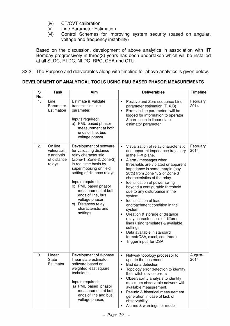
- Page 29 -
(iv) CT/CVT calibration (v) Line Parameter Estimation (vi) Control Schemes for improving system security (based on angular,
voltage and frequency instability) Based on the discussion, development of above analytics in association with IIT Bombay progressively in three(3) years has been undertaken which will be installed at all SLDC, RLDC, NLDC, RPC, CEA and CTU.
33.2 The Purpose and deliverables along with timeline for above analytics is given below. DEVELOPMENT OF ANALYTICAL TOOLS USING PMU BASED PHASOR MEASUREMENTS
S
No. Task Aim Deliverables Timeline
1. Line Parameter Estimation
Estimate & Validate transmission line parameter. Inputs required: a) PMU based phasor
measurement at both ends of line, bus voltage phasor
• Positive and Zero sequence Line parameter estimation (R,X,B)
• Errors in line parameters will be logged for information to operator & correction in linear state estimator parameter.
February 2014
2. On line vulnerability analysis of distance relays.
Development of software for validating distance relay characteristic (Zone-1, Zone-2, Zone-3) in real time basis by superimposing on field setting of distance relays. Inputs required: b) PMU based phasor
measurement at both ends of line, bus voltage phasor
c) Distances relay characteristic and settings.
• Visualization of relay characteristic and apparent impedance trajectory in the R-X plane.
• Alarm / messages when thresholds are violated or apparent impedance is some margin (say 20%) from Zone 1, 2 or Zone 3 characteristics of the relay.
• Identification of power swing beyond a configurable threshold due to any disturbance in the system
• Identification of load encroachment condition in the system
• Creation & storage of distance relay characteristics of different lines using templates & available settings
• Data available in standard format(CSV, excel, comtrade)
• Trigger input for DSA
February 2014
3. Linear State Estimator
Development of 3-phase linear state estimator, software based on weighted least square technique. Inputs required: a) PMU based phasor
measurement at both ends of line and bus voltage phasor,
• Network topology processor to update the bus model
• Bad data detection
• Topology error detection to identify the switch device errors
• Observability analysis to identify maximum observable network with available measurement.
• Pseudo & historical measurement generation in case of lack of observability.
• Alarms & warnings for model
August- 2014
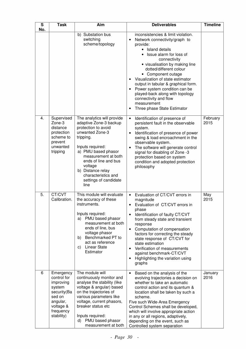
- Page 30 -
S No.
Task Aim Deliverables Timeline
b) Substation bus switching scheme/topology
inconsistencies & limit violation.
• Network connectivity/graph to provide:
• Island details
• Issue alarm for loss of connectivity
• visualisation by making line dotted/different colour
• Component outage
• Visualization of state estimator output in tabular & graphical form.
• Power system condition can be played-back along with topology connectivity and flow measurement
• Three phase State Estimator
4. Supervised Zone-3 distance protection scheme to prevent unwanted tripping
The analytics will provide adaptive Zone-3 backup protection to avoid unwanted Zone-3 tripping. Inputs required: a) PMU based phasor
measurement at both ends of line and bus voltage
b) Distance relay characteristics and settings of candidate line
• Identification of presence of persistent fault in the observable system.
• Identification of presence of power swing & load encroachment in the observable system.
• The software will generate control signal for disabling of Zone -3 protection based on system condition and adopted protection philosophy
February 2015
5. CT/CVT Calibration.
This module will evaluate the accuracy of these instruments. Inputs required: a) PMU based phasor
measurement at both ends of line, bus voltage phasor
b) Benchmarked PT to act as reference
c) Linear State Estimator
• Evaluation of CT/CVT errors in magnitude
• Evaluation of CT/CVT errors in phase
• Identification of faulty CT/CVT from steady state and transient response
• Computation of compensation factors for correcting the steady state response of CT/CVT for state estimation
• Verification of measurements against benchmark-CT/CVT
• Highlighting the variation using graphs
May 2015
6 Emergency control for improving system security(Based on angular, voltage & frequency stability)
The module will continuously monitor and analyse the stability (like voltage & angular) based on the trajectories of various parameters like voltage, current phasors, breaker status etc Inputs required: d) PMU based phasor
measurement at both
• Based on the analysis of the evolving trajectories a decision on whether to take an automatic control action and its quantum & location shall be taken by such a scheme.
Five such Wide-Area Emergency Control Schemes shall be developed, which will involve appropriate action in any or all regions, adaptively, depending on the event, such as Controlled system separation
January 2016
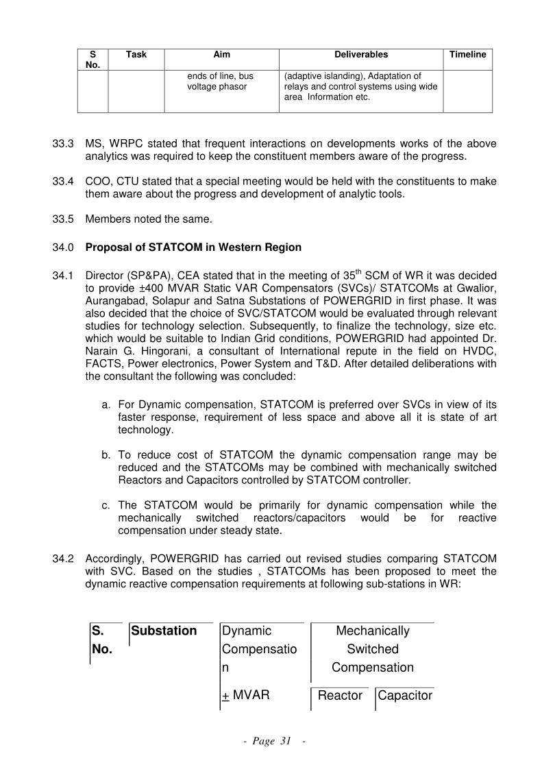
- Page 31 -
S No.
Task Aim Deliverables Timeline
ends of line, bus voltage phasor
(adaptive islanding), Adaptation of relays and control systems using wide area Information etc.
33.3 MS, WRPC stated that frequent interactions on developments works of the above
analytics was required to keep the constituent members aware of the progress. 33.4 COO, CTU stated that a special meeting would be held with the constituents to make
them aware about the progress and development of analytic tools. 33.5 Members noted the same.
34.0 Proposal of STATCOM in Western Region
34.1 Director (SP&PA), CEA stated that in the meeting of 35th SCM of WR it was decided to provide ±400 MVAR Static VAR Compensators (SVCs)/ STATCOMs at Gwalior, Aurangabad, Solapur and Satna Substations of POWERGRID in first phase. It was also decided that the choice of SVC/STATCOM would be evaluated through relevant studies for technology selection. Subsequently, to finalize the technology, size etc. which would be suitable to Indian Grid conditions, POWERGRID had appointed Dr. Narain G. Hingorani, a consultant of International repute in the field on HVDC, FACTS, Power electronics, Power System and T&D. After detailed deliberations with the consultant the following was concluded:
a. For Dynamic compensation, STATCOM is preferred over SVCs in view of its faster response, requirement of less space and above all it is state of art technology.
b. To reduce cost of STATCOM the dynamic compensation range may be
reduced and the STATCOMs may be combined with mechanically switched Reactors and Capacitors controlled by STATCOM controller.
c. The STATCOM would be primarily for dynamic compensation while the
mechanically switched reactors/capacitors would be for reactive compensation under steady state.
34.2 Accordingly, POWERGRID has carried out revised studies comparing STATCOM with SVC. Based on the studies , STATCOMs has been proposed to meet the dynamic reactive compensation requirements at following sub-stations in WR:
Mechanically
Switched
Compensation
S.
No.
Substation Dynamic
Compensatio
n
+ MVAR Reactor Capacitor
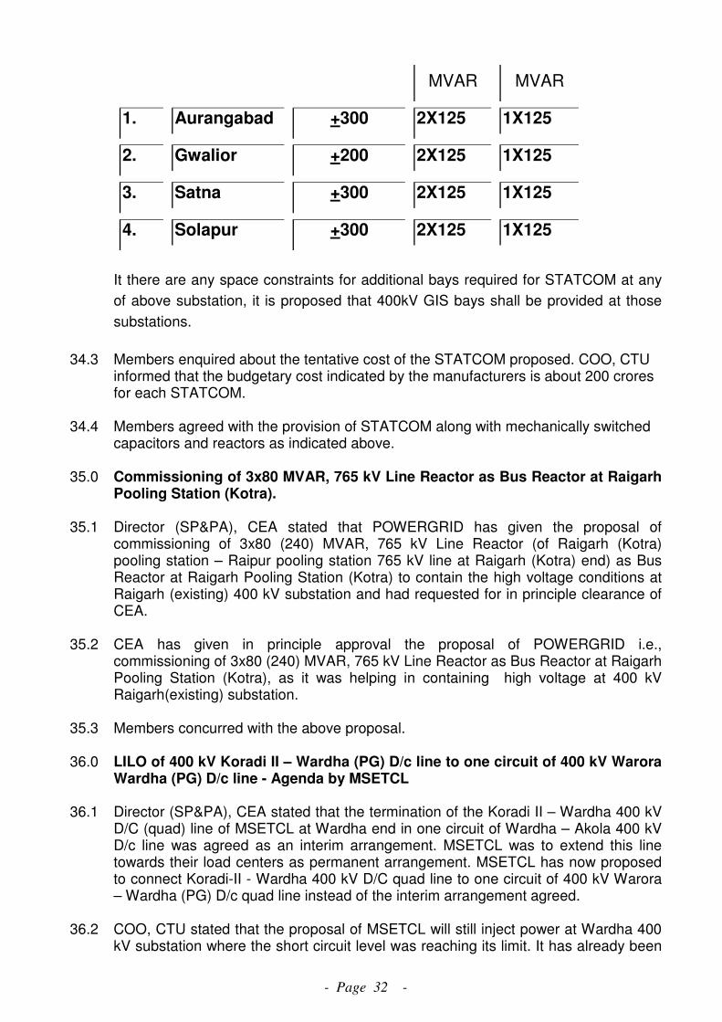
- Page 32 -
MVAR MVAR
1. Aurangabad +300 2X125 1X125
2. Gwalior +200 2X125 1X125
3. Satna +300 2X125 1X125
4. Solapur +300 2X125 1X125
It there are any space constraints for additional bays required for STATCOM at any
of above substation, it is proposed that 400kV GIS bays shall be provided at those
substations.
34.3 Members enquired about the tentative cost of the STATCOM proposed. COO, CTU
informed that the budgetary cost indicated by the manufacturers is about 200 crores for each STATCOM.
34.4 Members agreed with the provision of STATCOM along with mechanically switched
capacitors and reactors as indicated above. 35.0 Commissioning of 3x80 MVAR, 765 kV Line Reactor as Bus Reactor at Raigarh
Pooling Station (Kotra).
35.1 Director (SP&PA), CEA stated that POWERGRID has given the proposal of commissioning of 3x80 (240) MVAR, 765 kV Line Reactor (of Raigarh (Kotra) pooling station – Raipur pooling station 765 kV line at Raigarh (Kotra) end) as Bus Reactor at Raigarh Pooling Station (Kotra) to contain the high voltage conditions at Raigarh (existing) 400 kV substation and had requested for in principle clearance of CEA.
35.2 CEA has given in principle approval the proposal of POWERGRID i.e., commissioning of 3x80 (240) MVAR, 765 kV Line Reactor as Bus Reactor at Raigarh Pooling Station (Kotra), as it was helping in containing high voltage at 400 kV Raigarh(existing) substation.
35.3 Members concurred with the above proposal.
36.0 LILO of 400 kV Koradi II – Wardha (PG) D/c line to one circuit of 400 kV Warora Wardha (PG) D/c line - Agenda by MSETCL
36.1 Director (SP&PA), CEA stated that the termination of the Koradi II – Wardha 400 kV D/C (quad) line of MSETCL at Wardha end in one circuit of Wardha – Akola 400 kV D/c line was agreed as an interim arrangement. MSETCL was to extend this line towards their load centers as permanent arrangement. MSETCL has now proposed to connect Koradi-II - Wardha 400 kV D/C quad line to one circuit of 400 kV Warora – Wardha (PG) D/c quad line instead of the interim arrangement agreed.
36.2 COO, CTU stated that the proposal of MSETCL will still inject power at Wardha 400 kV substation where the short circuit level was reaching its limit. It has already been
- Page 33 -
agreed in various meetings that the 400 kV D/C line from Koradi-II towards Wardha has to be extended and connected to some load centers. MSETCL has not given any proposal for termination of the line from Koradi-II.
36.3 MSETCL informed that they planned an intra-state system strengthening scheme for
evacuation of power from IPPs such as Lanco Vidarbha , Jinbhuish etc. which included creation of 765/400 kV pooling station at Wardha. They have planned to terminate the 400 kV D/C line from Koradi-II at their Wardha pooling station. The intra state system strengthening scheme was also discussed in the 35th SCM of WR. But due to uncertainty of some IPP generation projects, MSETCL is reviewing the intra-state system strengthening scheme.
36.4 After deliberation, Members agreed with the proposal of MSETCL to terminate
Koradi-II - Wardha 400 kV D/C quad line to one circuit of 400 kV Warora – Wardha (PG) D/c quad line as interim arrangement. MSETCL was also advised to expedite establishment of their Wardha pooling station.
37.0 Installation of Shunt Reactor at Dabhol 37.1 Director (SP&PA), CEA stated that Ratnagiri Gas & Power Pvt. Ltd. (RGPPL) in a
letter addressed to MS, WRPC has informed that RGPPL has experiences black out twice in the recent past due to over voltage tripping of all the lines from RGPPL. The issue has been discussed in the 449th and 450th OCC meeting, where in it was suggested that a reactor of suitable rating be installed at RGPPL generating switchyard.
37.2 The issue was of over voltage at RGPPL was discussed and provision of 400 kV,
1X125 MVAR bus reactor at RGPPL generation switchyard to control over voltage was agreed by the members.
38.0 Open Access Meeting.
38.1 The minutes of the Connectivity, Open Access (Medium term and Long term) cases discussed in the 18th meeting of WR constituents regarding Connectivity / Long Term Access (LTA) applications in Western Region are available on the POWERGRID website.
The meeting ended with thanks to the chair.
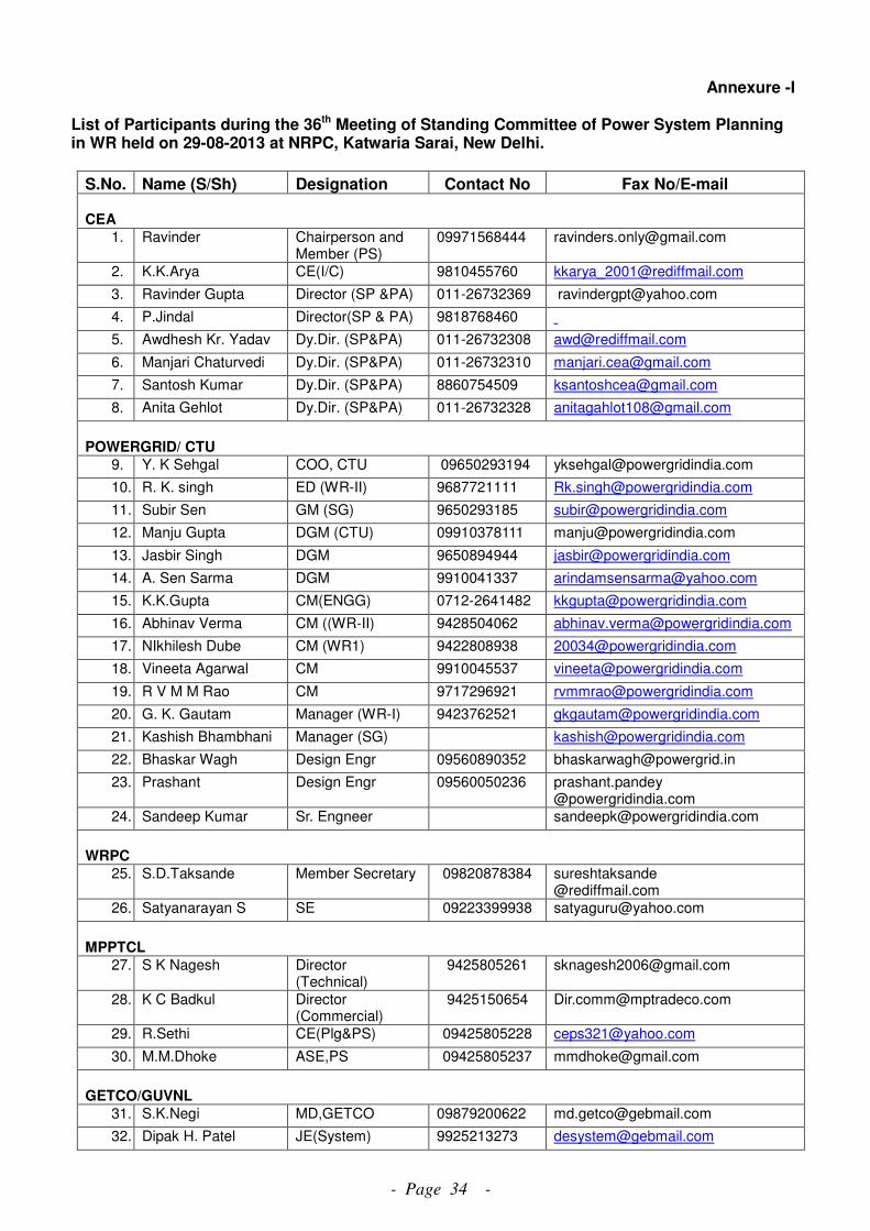
- Page 34 -
Annexure -I
List of Participants during the 36th Meeting of Standing Committee of Power System Planning in WR held on 29-08-2013 at NRPC, Katwaria Sarai, New Delhi.
S.No. Name (S/Sh) Designation Contact No Fax No/E-mail
CEA
1. Ravinder Chairperson and Member (PS)
09971568444 [email protected]
2. K.K.Arya CE(I/C) 9810455760 [email protected]
3. Ravinder Gupta Director (SP &PA) 011-26732369 [email protected]
4. P.Jindal Director(SP & PA) 9818768460
5. Awdhesh Kr. Yadav Dy.Dir. (SP&PA) 011-26732308 [email protected]
6. Manjari Chaturvedi Dy.Dir. (SP&PA) 011-26732310 [email protected]
7. Santosh Kumar Dy.Dir. (SP&PA) 8860754509 [email protected]
8. Anita Gehlot Dy.Dir. (SP&PA) 011-26732328 [email protected]
POWERGRID/ CTU
9. Y. K Sehgal COO, CTU 09650293194 [email protected]
10. R. K. singh ED (WR-II) 9687721111 [email protected]
11. Subir Sen GM (SG) 9650293185 [email protected]
12. Manju Gupta DGM (CTU) 09910378111 [email protected]
13. Jasbir Singh DGM 9650894944 [email protected]
14. A. Sen Sarma DGM 9910041337 [email protected]
15. K.K.Gupta CM(ENGG) 0712-2641482 [email protected]
16. Abhinav Verma CM ((WR-II) 9428504062 [email protected]
17. NIkhilesh Dube CM (WR1) 9422808938 [email protected]
18. Vineeta Agarwal CM 9910045537 [email protected]
19. R V M M Rao CM 9717296921 [email protected]
20. G. K. Gautam Manager (WR-I) 9423762521 [email protected]
21. Kashish Bhambhani Manager (SG) [email protected]
22. Bhaskar Wagh Design Engr 09560890352 [email protected]
23. Prashant Design Engr 09560050236 prashant.pandey @powergridindia.com
24. Sandeep Kumar Sr. Engneer [email protected]
WRPC
25. S.D.Taksande Member Secretary 09820878384 sureshtaksande @rediffmail.com
26. Satyanarayan S SE 09223399938 [email protected]
MPPTCL
27. S K Nagesh Director (Technical)
9425805261 [email protected]
28. K C Badkul Director (Commercial)
9425150654 [email protected]
29. R.Sethi CE(Plg&PS) 09425805228 [email protected]
30. M.M.Dhoke ASE,PS 09425805237 [email protected]
GETCO/GUVNL
31. S.K.Negi MD,GETCO 09879200622 [email protected]
32. Dipak H. Patel JE(System) 9925213273 [email protected]
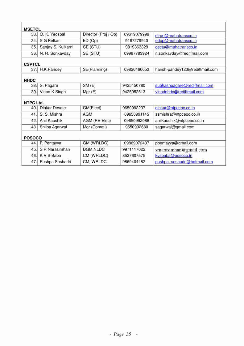
- Page 35 -
MSETCL
33. O. K. Yeospal Director (Proj / Op) 09619079999 [email protected]
34. S G Kelkar ED (Op) 9167279940 [email protected]
35. Sanjay S. Kulkarni CE (STU) 9819363329 [email protected]
36. N. R. Sonkavday SE (STU) 09987783924 [email protected]
CSPTCL
37. H.K.Pandey SE(Planning) 09826460053 [email protected]
NHDC
38. S. Pagare SM (E) 9425450780 [email protected]
39. Vinod K Singh Mgr (E) 9425952513 [email protected]
NTPC Ltd.
40. Dinkar Devate GM(Elect) 9650992237 [email protected]
41. S. S. Mishra AGM 09650991145 [email protected]
42. Anil Kaushik AGM (PE-Elec) 09650992088 [email protected]
43. Shilpa Agarwal Mgr (Comml) 9650992680 [email protected]
POSOCO
44. P. Pentayya GM (WRLDC) 09869072437 [email protected]
45. S R Narasimhan DGM,NLDC 9971117022 [email protected]
46. K V S Baba CM (WRLDC) 8527607575 [email protected]
47. Pushpa Seshadri CM, WRLDC 9869404482 [email protected]

- Page 36 -
Annexure-II
Sl.
No. Description of Scheme
Est.
Cost
(Rs.
Cr)
Date of
firming up
in WR
standing
committee
Date of
FR
Date of
investment
approval
Target date as
of now Remarks
1
Western Region System
Strengthening Scheme-
II
5222 20
th
(23.01.04)
Sep’05
(Rev) July’06
Set-A: For absorbing
import in eastern and
central part of WR Grid
(POWERGRID)
1700 commissioned
Set-B: For regional
strengthening in
Southern Maharashtra
(100 % private)
1050 Nov'13 Implementation
by Reliance
a) Parli(PG) - Pune
400kV D/c Nov'13
b) Pune – Aurangabad
400kV D/c Nov'13
c) Parli(PG) – Solapur
400kV D/c commissioned
d) Solapur - Kolhapur
400kV D/c commissioned
e) LILO of Lonikhand –
Kalwa 400kV D/c line at
Pune
commissioned
f) LILO of Sholapur –
Karad 400kV S/c line at
South Solapur
commissioned
Set-C: For regional
strengthening in Gujarat
(100 % private)
600 Nov'13 Implementation
by Reliance
a) Rajgarh – Karamsad
400kV D/c Nov'13
b) Limdi(Chorania) –
Ranchodpura 400kV D/c commissioned
c) Ranchodpura –
Zerda(Kansari) 400kV
D/c
commissioned
Set-D: For regional
Strengthening in
Northern Madhya
Pradesh (POWERGRID)
1050 commissioned
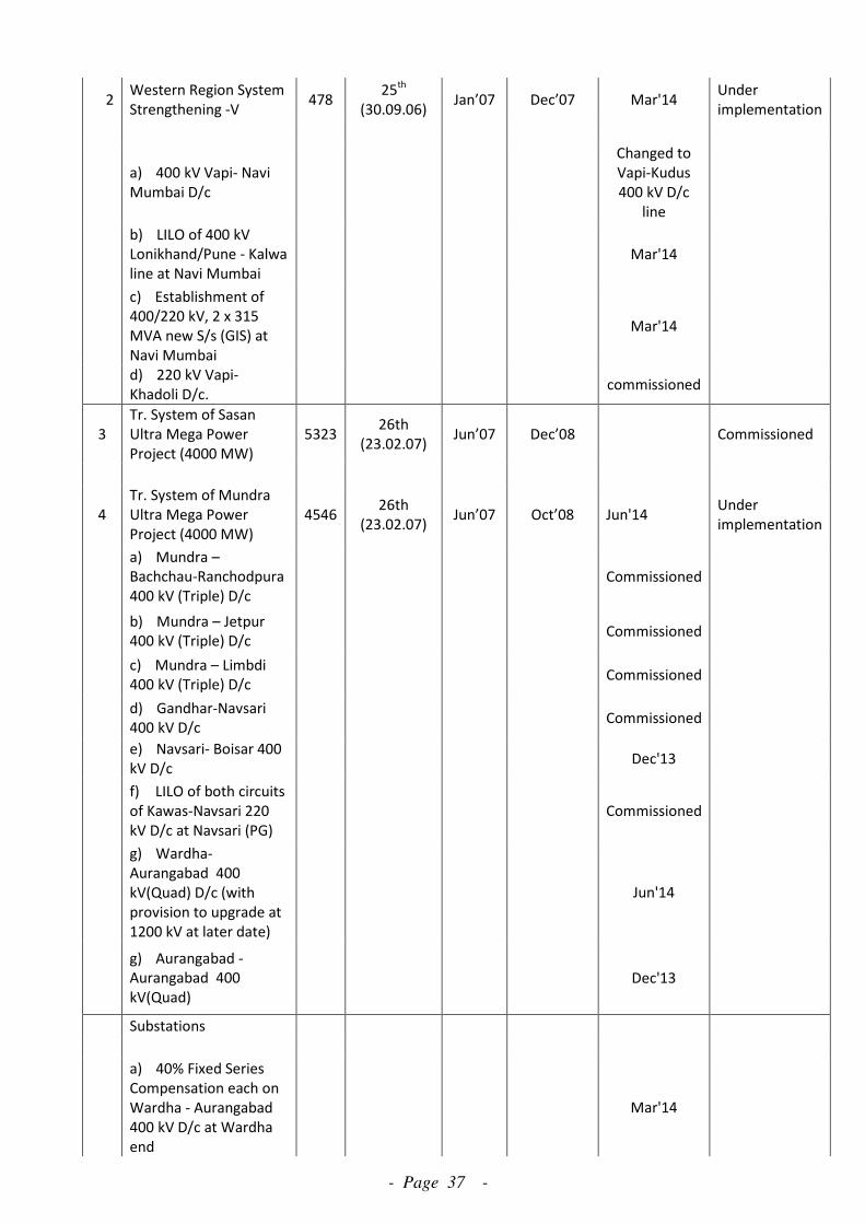
- Page 37 -
2 Western Region System
Strengthening -V 478
25th
(30.09.06) Jan’07 Dec’07 Mar'14
Under
implementation
a) 400 kV Vapi- Navi
Mumbai D/c
Changed to
Vapi-Kudus
400 kV D/c
line
b) LILO of 400 kV
Lonikhand/Pune - Kalwa
line at Navi Mumbai
Mar'14
c) Establishment of
400/220 kV, 2 x 315
MVA new S/s (GIS) at
Navi Mumbai
Mar'14
d) 220 kV Vapi-
Khadoli D/c. commissioned
3
Tr. System of Sasan
Ultra Mega Power
Project (4000 MW)
5323 26th
(23.02.07) Jun’07 Dec’08 Commissioned
4
Tr. System of Mundra
Ultra Mega Power
Project (4000 MW)
4546 26th
(23.02.07) Jun’07 Oct’08 Jun'14
Under
implementation
a) Mundra –
Bachchau-Ranchodpura
400 kV (Triple) D/c
Commissioned
b) Mundra – Jetpur
400 kV (Triple) D/c Commissioned
c) Mundra – Limbdi
400 kV (Triple) D/c Commissioned
d) Gandhar-Navsari
400 kV D/c Commissioned
e) Navsari- Boisar 400
kV D/c Dec'13
f) LILO of both circuits
of Kawas-Navsari 220
kV D/c at Navsari (PG)
Commissioned
g) Wardha-
Aurangabad 400
kV(Quad) D/c (with
provision to upgrade at
1200 kV at later date)
Jun'14
g) Aurangabad -
Aurangabad 400
kV(Quad)
Dec'13
Substations
a) 40% Fixed Series
Compensation each on
Wardha - Aurangabad
400 kV D/c at Wardha
end
Mar'14
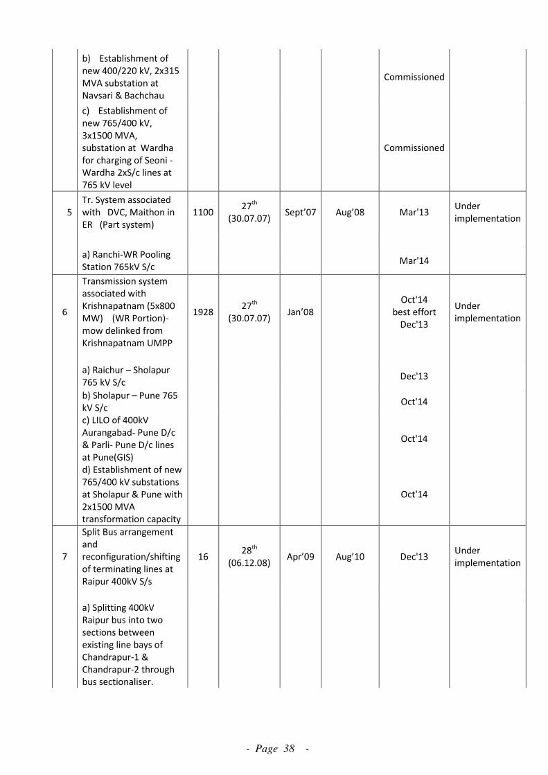
- Page 38 -
b) Establishment of
new 400/220 kV, 2x315
MVA substation at
Navsari & Bachchau
Commissioned
c) Establishment of
new 765/400 kV,
3x1500 MVA,
substation at Wardha
for charging of Seoni -
Wardha 2xS/c lines at
765 kV level
Commissioned
5
Tr. System associated
with DVC, Maithon in
ER (Part system)
1100 27
th
(30.07.07) Sept’07 Aug’08 Mar'13
Under
implementation
a) Ranchi-WR Pooling
Station 765kV S/c Mar'14
6
Transmission system
associated with
Krishnapatnam (5x800
MW) (WR Portion)-
mow delinked from
Krishnapatnam UMPP
1928 27
th
(30.07.07) Jan’08
Oct'14
best effort
Dec'13
Under
implementation
a) Raichur – Sholapur
765 kV S/c Dec'13
b) Sholapur – Pune 765
kV S/c Oct'14
c) LILO of 400kV
Aurangabad- Pune D/c
& Parli- Pune D/c lines
at Pune(GIS)
Oct'14
d) Establishment of new
765/400 kV substations
at Sholapur & Pune with
2x1500 MVA
transformation capacity
Oct'14
7
Split Bus arrangement
and
reconfiguration/shifting
of terminating lines at
Raipur 400kV S/s
16 28
th
(06.12.08) Apr’09 Aug’10 Dec'13
Under
implementation
a) Splitting 400kV
Raipur bus into two
sections between
existing line bays of
Chandrapur-1 &
Chandrapur-2 through
bus sectionaliser.

- Page 39 -
b) Bypass 400kV
Bhatapara-Raipur-Bhilai
line at Raipur and
restore the line as
400kV Bhatapara-Bhilai
S/c
c) Shifting of
Chandrapur-2 and
Chandrapur-3 line bays
from Section Raipur-B*
to Raipur-A*.
8
Associated transmission
system of VSTPP-IV and
Rihand-III
4673 29th
(10.09.09) Sep’09 Mar’10 Mar'14
Under
implementation
a) Rihand-III-
Vindhyachal Pool 765
kV D/c (initially to be
op. at 400kV)
Mar'14
b) Vindhyachal-IV
Vindhyachal Pool 400kV
D/c(Quad)
Commissioned
c) Vindhyachal Pool-
Satna 765 kV 2xS/c
Mar'14
d) Satna -Gwalior 765
kV 2xS/c
Dec'13
e) Gwalior –
Jaipur(South) 765 kV S/c
Dec'13
f) Vindhyachal Pool-
Sasan 765 kV S/c
Mar'14
g) Vindhyachal Pool-
Sasan 400 kV D/c
Commissioned
h) Establishment of
765/400kV, 2x1500
MVA substation at
Vindhyachal Pool
Mar'15
9
Establishment of
400/220kV substation in
UT DNH
181 28
th
(06.12.08) Jan’10 Jul’11 Dec'13
Under
implementation
a) LILO of Vapi- Navi
Mumbai 400kV D/c at
Kala S/s in UT DNH
Dec'13
b) Establishment of
400/220kV, 2x315 MVA
substation at Kala in UT
DNH
Dec'13
10
Installation of
transformer at Vapi sub
station
21 30
th
(08.07.10) Nov’10 Sep’11 Commissioned

- Page 40 -
a) Installation of
400/220kV, 1x315MVA
transformer (3rd) at
Vapi(PG)
11
Establishment of
400/220kV substation in
UT Daman
234 30
th
(08.07.10) Mar’10 Jan'12
Under
implementation
a) LILO of Navsari-
Boisar 400kV D/c at
Magarwada in UT
Daman-30 km
Jan'14
b) Establishment of
400/220kV, 2x315 MVA
substation at
Magarwada
Jan'14
12
Western Region System
Strengthening Scheme-
XIII
49 30
th
(08.07.10) Jan’11 Dec'11 Mar'14
Under
implementation
a) Bachau(PG) –
Versana(GETCO) 400kV
D/c-10 km
Mar'14
13
Solapur
STPP(2x660MW)
transmission system
630 30th
(08.07.10) Jul’11 Sep'13 June'15
Tendering
under progress
a) Solapur STPP –
Solapur (PG) 400kV D/c
b) Solapur STPP –
Pune(PG) [Pune S/s
under Krishnapatnam
UMPP] 400kV D/c
(Quad)
c) Augmentation of
400/220kV ICT by
1x315MVA transformer
(3rd
) at Solapur (PG)
14
Augmentation of
transformer and bays in
Western Region
65 30th/32nd
(WR SCM) Aug’11 June'12 June'14
Under
implementation
a) Installation of
400/220kV, 1x315MVA
transformer (3rd) at
Mapusa(PG) along with
2 nos. 220kV line bays
at Mapusa (PG) sub
station
b) Installation of
400/220kV, 1x500MVA
transformer (3rd) at
Navsari
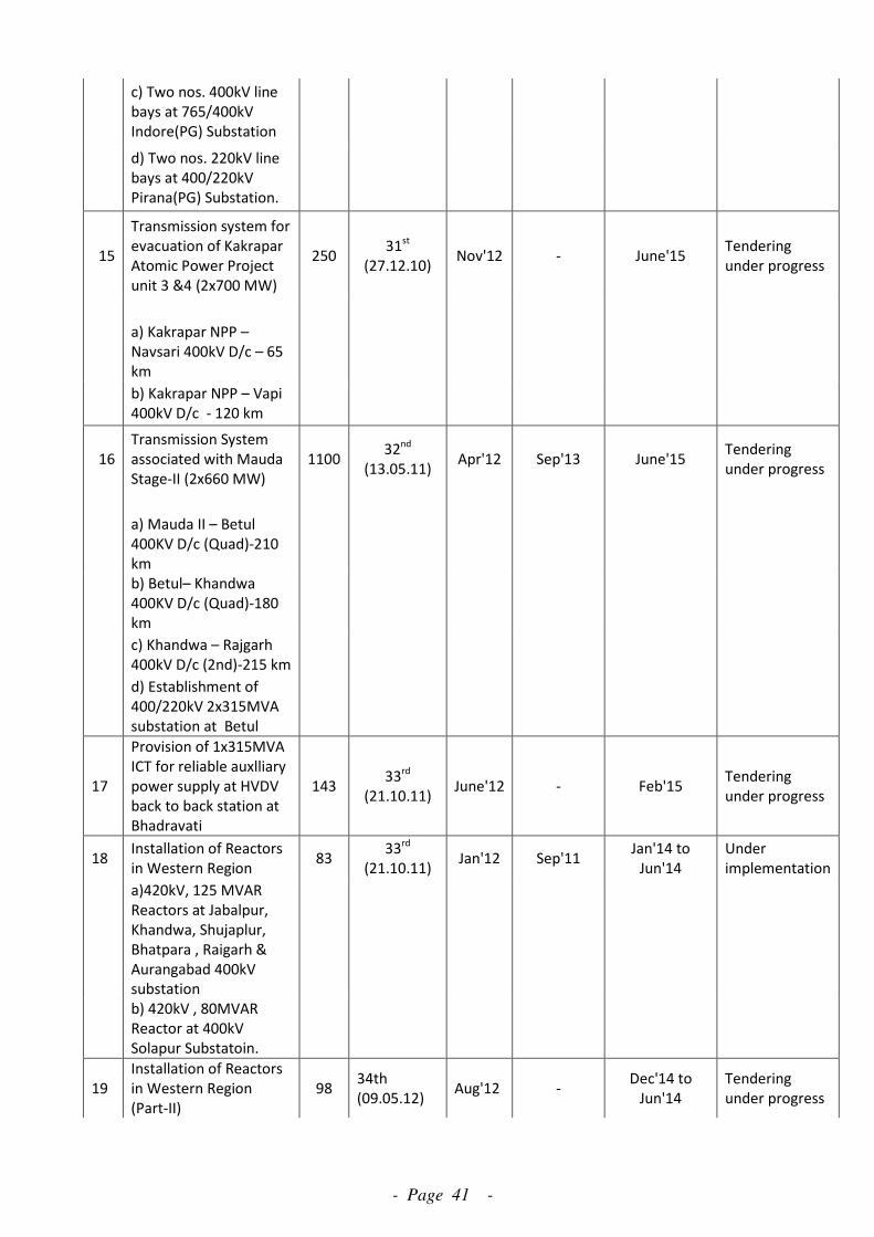
- Page 41 -
c) Two nos. 400kV line
bays at 765/400kV
Indore(PG) Substation
d) Two nos. 220kV line
bays at 400/220kV
Pirana(PG) Substation.
15
Transmission system for
evacuation of Kakrapar
Atomic Power Project
unit 3 &4 (2x700 MW)
250 31
st
(27.12.10) Nov'12 - June'15
Tendering
under progress
a) Kakrapar NPP –
Navsari 400kV D/c – 65
km
b) Kakrapar NPP – Vapi
400kV D/c - 120 km
16
Transmission System
associated with Mauda
Stage-II (2x660 MW)
1100 32
nd
(13.05.11) Apr'12 Sep'13 June'15
Tendering
under progress
a) Mauda II – Betul
400KV D/c (Quad)-210
km
b) Betul– Khandwa
400KV D/c (Quad)-180
km
c) Khandwa – Rajgarh
400kV D/c (2nd)-215 km
d) Establishment of
400/220kV 2x315MVA
substation at Betul
17
Provision of 1x315MVA
ICT for reliable auxlliary
power supply at HVDV
back to back station at
Bhadravati
143 33
rd
(21.10.11) June'12 - Feb'15
Tendering
under progress
18 Installation of Reactors
in Western Region 83
33rd
(21.10.11) Jan'12 Sep'11
Jan'14 to
Jun'14
Under
implementation
a)420kV, 125 MVAR
Reactors at Jabalpur,
Khandwa, Shujaplur,
Bhatpara , Raigarh &
Aurangabad 400kV
substation
b) 420kV , 80MVAR
Reactor at 400kV
Solapur Substatoin.
19
Installation of Reactors
in Western Region
(Part-II)
98 34th
(09.05.12) Aug'12 -
Dec'14 to
Jun'14
Tendering
under progress
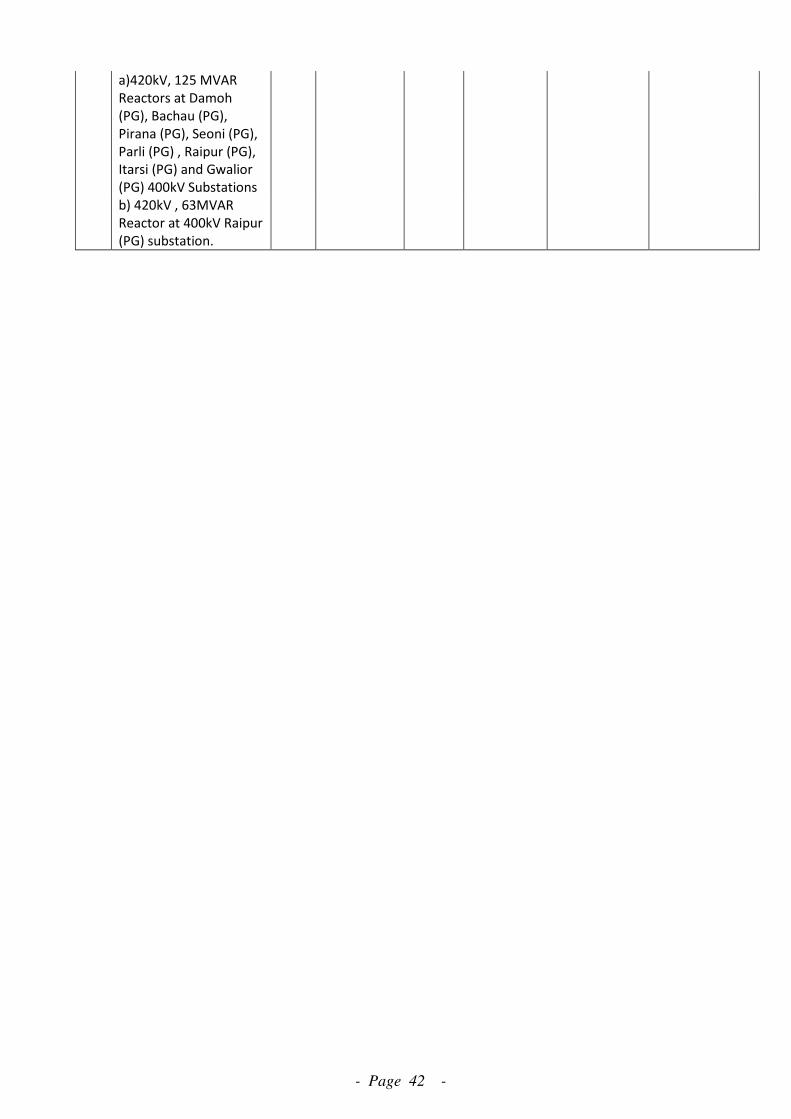
- Page 42 -
a)420kV, 125 MVAR
Reactors at Damoh
(PG), Bachau (PG),
Pirana (PG), Seoni (PG),
Parli (PG) , Raipur (PG),
Itarsi (PG) and Gwalior
(PG) 400kV Substations
b) 420kV , 63MVAR
Reactor at 400kV Raipur
(PG) substation.
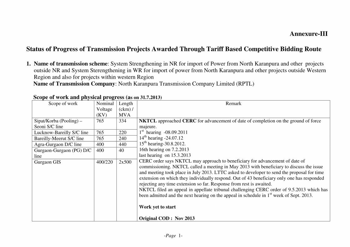
-Page 1-
Annexure-III
Status of Progress of Transmission Projects Awarded Through Tariff Based Competitive Bidding Route
1. Name of transmission scheme: System Strengthening in NR for import of Power from North Karanpura and other projects
outside NR and System Sterengthening in WR for import of power from North Karanpura and other projects outside Western
Region and also for projects within western Region
Name of Transmission Company: North Karanpura Transmission Company Limited (RPTL)
Scope of work and physical progress (as on 31.7.2013)
Scope of work Nominal
Voltage
(KV)
Length
(ckm) /
MVA
Remark
Sipat/Korba (Pooling) –
Seoni S/C line
765 334
Lucknow-Bareilly S/C line 765 220
Bareilly-Meerut S/C line 765 240
Agra-Gurgaon D/C line 400 440
Gurgaon-Gurgaon (PG) D/C
line
400 40
Gurgaon GIS 400/220 2x500
NKTCL approached CERC for advancement of date of completion on the ground of force
majeure.
1st hearing -08.09.2011
14th
hearing -24.07.12
15th
hearing-30.8.2012.
16th hearing on 7.2.2013
last hearing on 15.3.2013
CERC order says NKTCL may approach to beneficiary for advancement of date of
commissioning. NKTCL called a meeting in May 2013 with beneficiary to discuss the issue
and meeting took place in July 2013. LTTC asked to developer to send the proposal for time
extension on which they individually respond. Out of 43 beneficiary only one has responded
rejecting any time extension so far. Response from rest is awaited.
NKTCL filed an appeal in appellate tribunal challenging CERC order of 9.5.2013 which has
been admitted and the next hearing on the appeal in schedule in 1st week of Sept. 2013.
Work yet to start
Original COD : Nov 2013
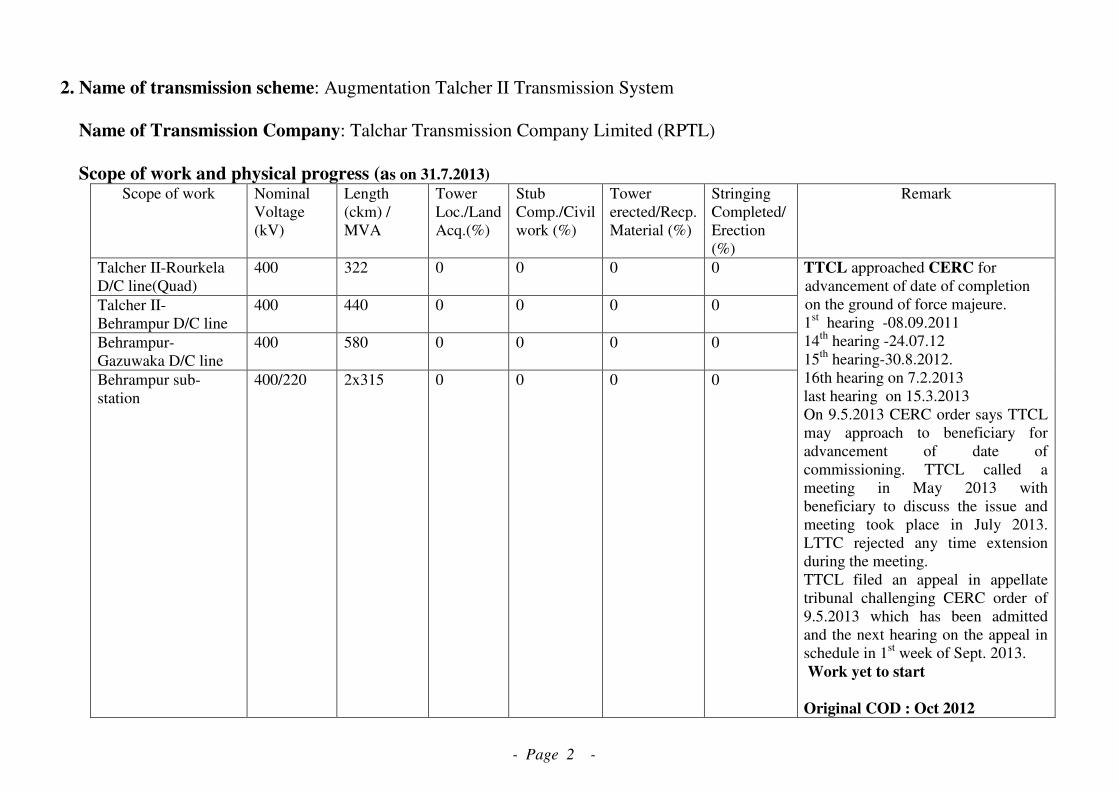
- Page 2 -
2. Name of transmission scheme: Augmentation Talcher II Transmission System
Name of Transmission Company: Talchar Transmission Company Limited (RPTL)
Scope of work and physical progress (as on 31.7.2013)
Scope of work Nominal
Voltage
(kV)
Length
(ckm) /
MVA
Tower
Loc./Land
Acq.(%)
Stub
Comp./Civil
work (%)
Tower
erected/Recp.
Material (%)
Stringing
Completed/
Erection
(%)
Remark
Talcher II-Rourkela
D/C line(Quad)
400 322 0 0 0 0
Talcher II-
Behrampur D/C line
400 440 0 0 0 0
Behrampur-
Gazuwaka D/C line
400 580 0 0 0 0
Behrampur sub-
station
400/220 2x315 0 0 0 0
TTCL approached CERC for
advancement of date of completion
on the ground of force majeure.
1st hearing -08.09.2011
14th
hearing -24.07.12
15th
hearing-30.8.2012.
16th hearing on 7.2.2013
last hearing on 15.3.2013
On 9.5.2013 CERC order says TTCL
may approach to beneficiary for
advancement of date of
commissioning. TTCL called a
meeting in May 2013 with
beneficiary to discuss the issue and
meeting took place in July 2013.
LTTC rejected any time extension
during the meeting.
TTCL filed an appeal in appellate
tribunal challenging CERC order of
9.5.2013 which has been admitted
and the next hearing on the appeal in
schedule in 1st week of Sept. 2013.
Work yet to start
Original COD : Oct 2012
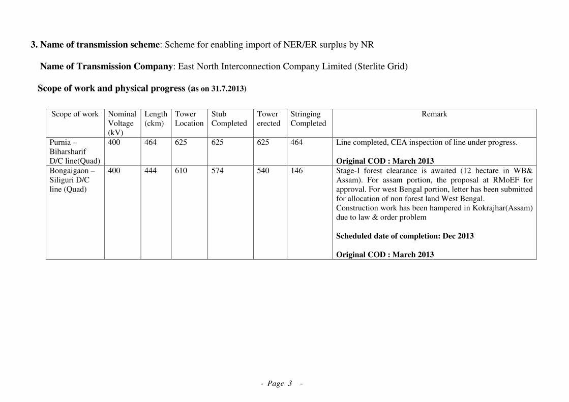
- Page 3 -
3. Name of transmission scheme: Scheme for enabling import of NER/ER surplus by NR
Name of Transmission Company: East North Interconnection Company Limited (Sterlite Grid)
Scope of work and physical progress (as on 31.7.2013)
Scope of work Nominal
Voltage
(kV)
Length
(ckm)
Tower
Location
Stub
Completed
Tower
erected
Stringing
Completed
Remark
Purnia –
Biharsharif
D/C line(Quad)
400 464 625 625 625 464 Line completed, CEA inspection of line under progress.
Original COD : March 2013
Bongaigaon –
Siliguri D/C
line (Quad)
400 444 610 574 540 146 Stage-I forest clearance is awaited (12 hectare in WB&
Assam). For assam portion, the proposal at RMoEF for
approval. For west Bengal portion, letter has been submitted
for allocation of non forest land West Bengal.
Construction work has been hampered in Kokrajhar(Assam)
due to law & order problem
Scheduled date of completion: Dec 2013
Original COD : March 2013

- Page 4 -
4. Name of transmission scheme: Scheme for System strengthening common for WR and NR
Name of Transmission Company: Jabalpur Transmission Company Limited (Sterlite Grid)
Scope of work and physical progress(as on 31-7-2013)
Scope of work Nominal
Voltage
(kV)
Length
(ckm)
Tower
Loc
Stub Comp Tower
erected/
Stringing
Completed
Remark
Dhramjaygarh-
Jabalpur D/C
line
765 754 980 664 175 0
Jabalpur-Bina
S/C line
765 236 610 493 340 67
(1) All type of tower testing completed.
(2) Tower material as per schedule
reached at site.
(3) FC awaited for Dhramjaygarh-
Jabalpur D/C line.
(4) PTCC clearance awaited
Scheduled date of completion: March 2014(original)

- Page 5 -
5. Name of transmission scheme : Transmission System Associated with Krishnapattnam UMPP – Synchronous
interconnection between SR and WR ( Part- B)
Name of Transmission Company: Raichur Solapur Transmission Company Limited (A consortium of Patel Engg. B S Tanscom
Ltd. and Simplex Infrastructure Ltd.)
Scope of work and physical progress(as on 31-7-2013)
Scope of work Nominal
Voltage
Length
(ckm)
Tower
Location
Stub
Completed
Tower
erected
Stringing
Completed
(KM)
Remark
Raichur-
Sholapur S/C
Line
765 kV 208 542 473 259 5 Tower material for A type tower
reached at site. B & D type tower
material yet to reach. Conductor and
hardware/insulator partially reached
at site, balance by Sept. end. Work on
pile foundation is yet to start.
Statuary clearance proposals are yet
to submit.
Scheduled date of completion: January 2014.(original)

- Page 6 -
6. Name of transmission scheme: Scheme for system strengthening for WR
Name of Transmission Company: Bhopal Dhule Transmission Company Limited (Sterlite Grid)
Scope of work and physical progress(as on 31-7-2013)
Scope of work Nominal
Voltage
(kV)
Length
(km) /
MVA
Tower
Loc./Land
Acq.(%)
Stub
Comp./
Civil
work (%)
Tower
erected/
Recp.
Material
(%)
Stringing
Complete
d/Erection
(%)
Remark
Jabalpur-Bhopal S/C Line 765 261 686 541 332 39 PGCIL started bay execution at Jabalpur
Bhopal-Indore S/C Line 765 174 455 450 287 26 PGCIL started bay execution at Indore
765/400 kV substation at
Bhopal, with 2x1500 MVA
765/400 kV
765/400
2x1500 100 24 67 0 Land leveling complete. Equip. supply
30%
Bhopal-Bhopal(MP) D/C Line 400 16 27 15 2 0 MPPTCL started Bay erection at Bhopal
Aurangabad-Dhule S/C Line 765 191 507 442 396 68 RoW issues affected progress. PGCIL
started bay execution at aurangabad
Dhule-Vadodara S/C Line 765 263 680 491 341 30 FC awaited, RoW issues affected
progress. PGCIL yet to start bay
execution at Vadodara
765/400 kV substation at
Dhule with 2x1500 MVA
765/400 kV
765/400
2x1500 100 88 85 25 Transformer dispatched. Balance equipts
received at site. Erection started. Cable
trench, road, CR u/p. other Civil Work
completed.
Dhule-Dhule(Mh) D/C Line 400 36 55 43 33 1 RoW issues affected progress, MSETCL
yet to start bay execution
Scheduled date of completion: Mar 2014.(original)
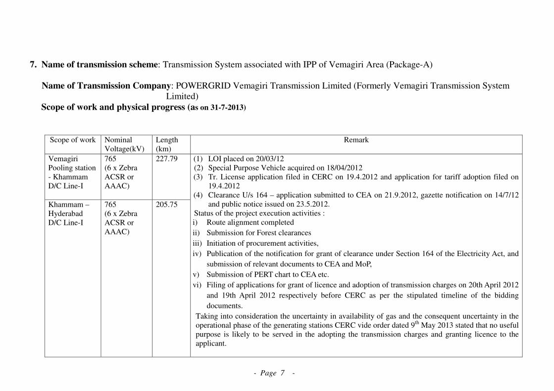
- Page 7 -
7. Name of transmission scheme: Transmission System associated with IPP of Vemagiri Area (Package-A)
Name of Transmission Company: POWERGRID Vemagiri Transmission Limited (Formerly Vemagiri Transmission System
Limited)
Scope of work and physical progress (as on 31-7-2013)
Scope of work Nominal
Voltage(kV)
Length
(km)
Remark
Vemagiri
Pooling station
- Khammam
D/C Line-I
765
(6 x Zebra
ACSR or
AAAC)
227.79
Khammam –
Hyderabad
D/C Line-I
765
(6 x Zebra
ACSR or
AAAC)
205.75
(1) LOI placed on 20/03/12
(2) Special Purpose Vehicle acquired on 18/04/2012
(3) Tr. License application filed in CERC on 19.4.2012 and application for tariff adoption filed on
19.4.2012
(4) Clearance U/s 164 – application submitted to CEA on 21.9.2012, gazette notification on 14/7/12
and public notice issued on 23.5.2012.
Status of the project execution activities :
i) Route alignment completed
ii) Submission for Forest clearances
iii) Initiation of procurement activities,
iv) Publication of the notification for grant of clearance under Section 164 of the Electricity Act, and
submission of relevant documents to CEA and MoP,
v) Submission of PERT chart to CEA etc.
vi) Filing of applications for grant of licence and adoption of transmission charges on 20th April 2012
and 19th April 2012 respectively before CERC as per the stipulated timeline of the bidding
documents.
Taking into consideration the uncertainty in availability of gas and the consequent uncertainty in the
operational phase of the generating stations CERC vide order dated 9th
May 2013 stated that no useful
purpose is likely to be served in the adopting the transmission charges and granting licence to the
applicant.

- Page 8 -
Further, CERC in the aforementioned order stated that there is a need to examine the possibility of
reconfiguring the required network in the Southern Region based on expected generation and the load
and some elements of the transmission system may be combined with the other transmission systems
being built / proposed to be built in the Region, if required. The Central Electricity Authority and the
Central Transmission Utility were directed to undertake necessary review and re-examination of the
entire matter afresh and file their decision/views in the matter.
Presently licence has not been issued for implementing the project and the transmission charges are
also not adopted.
8. Name of transmission scheme: Transmission System associated with IPP of Nagapattinam/Cuddalore (Package-A)
Name of Transmission Company: POWERGRID NM Transmission Limited (Formerly Nagapattinam-Madhugiri Transmission
Company Limited)
Scope of work and physical progress (as on 31-7-2013)
Scope of work Nominal
Voltage
(kV)
Length (km) Remark
Nagapattinam
Pooling
station- Salem
D/C line
765 211.73
Salem-
Madhugiri S/C
line
765 234.461
(1) LOI placed on 06/03/12
(2) Special Purpose Vehicle acquired on 29/03/2012
(3) Tr. License application filed in CERC on 4.4.2012 and application for tariff adoption filed on
4.4.2012. Tr. License issued on 15.7.2013 and tariff adoption by CERC on 9.5.2013.
(4) Clearance U/s 164 – application submitted to CEA on 17.9.2012, gazette notification on 7/7/12
and public notice issued on 20.6.2012.
Status of the project execution activities :
i) Route alignment completed
ii) Submission for Forest clearances
iii) Initiation of procurement activities,
iv) Publication of the notification for grant of clearance under Section 164 of the Electricity Act,
and submission of relevant documents to CEA and MoP,
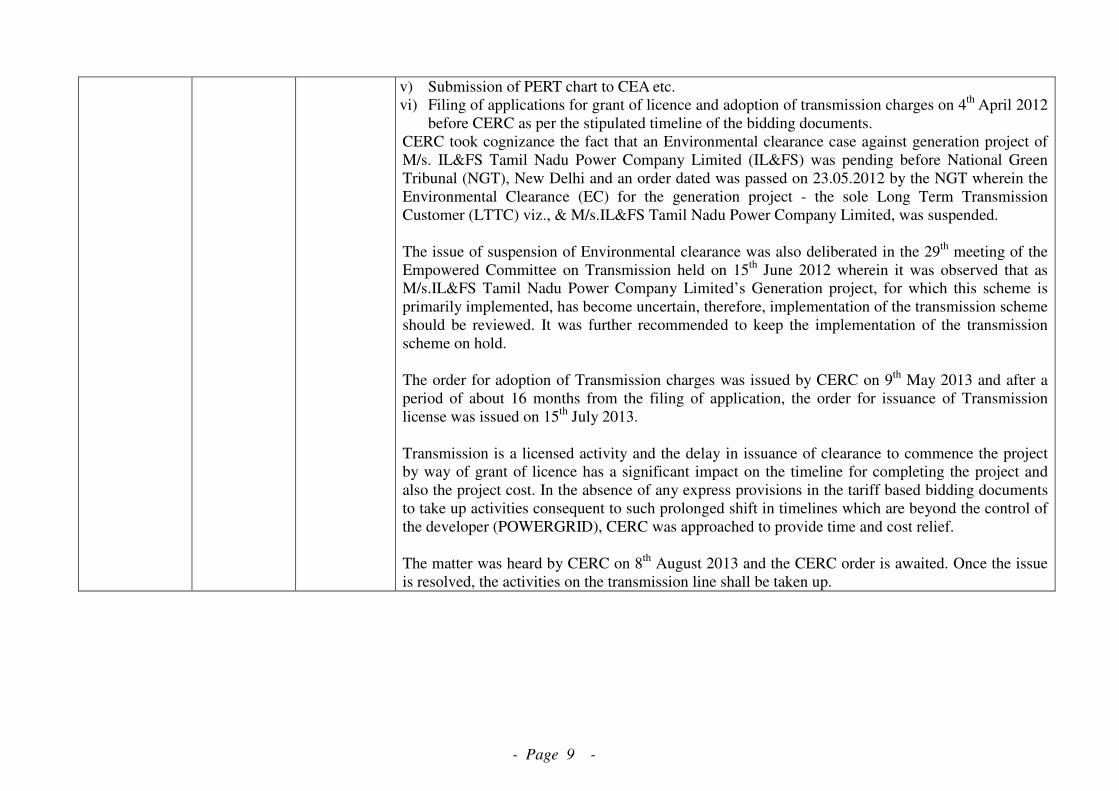
- Page 9 -
v) Submission of PERT chart to CEA etc.
vi) Filing of applications for grant of licence and adoption of transmission charges on 4th
April 2012
before CERC as per the stipulated timeline of the bidding documents.
CERC took cognizance the fact that an Environmental clearance case against generation project of
M/s. IL&FS Tamil Nadu Power Company Limited (IL&FS) was pending before National Green
Tribunal (NGT), New Delhi and an order dated was passed on 23.05.2012 by the NGT wherein the
Environmental Clearance (EC) for the generation project - the sole Long Term Transmission
Customer (LTTC) viz., & M/s.IL&FS Tamil Nadu Power Company Limited, was suspended.
The issue of suspension of Environmental clearance was also deliberated in the 29th
meeting of the
Empowered Committee on Transmission held on 15th
June 2012 wherein it was observed that as
M/s.IL&FS Tamil Nadu Power Company Limited’s Generation project, for which this scheme is
primarily implemented, has become uncertain, therefore, implementation of the transmission scheme
should be reviewed. It was further recommended to keep the implementation of the transmission
scheme on hold.
The order for adoption of Transmission charges was issued by CERC on 9th
May 2013 and after a
period of about 16 months from the filing of application, the order for issuance of Transmission
license was issued on 15th
July 2013.
Transmission is a licensed activity and the delay in issuance of clearance to commence the project
by way of grant of licence has a significant impact on the timeline for completing the project and
also the project cost. In the absence of any express provisions in the tariff based bidding documents
to take up activities consequent to such prolonged shift in timelines which are beyond the control of
the developer (POWERGRID), CERC was approached to provide time and cost relief.
The matter was heard by CERC on 8th
August 2013 and the CERC order is awaited. Once the issue
is resolved, the activities on the transmission line shall be taken up.

-Page 1-
Annexure-IV Details of IPP Projects in Chhattisgarh
S. No.
Applicant Ins. Capacity (in MW)
Commiss. Schedule
PPA Status
RAIGARH(KOTRA) COMPLEX
1 RKM Powergen Ltd.(4x360) 1440 Oct’13 Signed PPA with CSEB and PTC.
2 Athena Chhattisgarh Power Ltd.(2x600)
1200 Jun’14 Signed PPA with PTC for 1100 MW who in turn have signed PPA with CSPTCL (444 MW) and received Lol from UPPCL for 300 MW and PPA signed with Nepal Electricity Authority for 150MW.
3 SKS Power Gen. (Ch) Ltd.(4x300)
1200 Jun’14 Signed PPA for 37.5% of the project capacity with CSPTCL.
4 Korba West Power Co. Ltd.(1x600)
600 Oct’13 letter of comfort for 35% from CSPTCL has been received.
5 DB Power Ltd.(2x600) 1200 Oct’13 Signed PPA with CSPTCL – 450 MW, Tamil Nadu – 208 MW
6 Visa Power Ltd. (1x600+1x660)
1260 Mar’15 Signed PPA with WBSEDCL for 200 MW with an option to increase upto 510 MW and also signed PPA with CSPTCL (424 MW).
RAIGARH(TAMNAR) COMPLEX
1 Jindal Power Ltd.(4x600) 2400 Sep’13 Tamil Nadu – 400 MW
2 Jindal Power Ltd. (225 MW from Dongamahua CPP+ 175MW from existing Tamnar TPS
400 Existing -
3 TRN Energy Pvt. Ltd.(2x300) 600 Mar’14 UP – 390 MW
4. Jayaswal Neco(2x300MW) 600 Sep’16 As per MoU with state Govt., GoCG shall purchase 37.5% power and no other PPA has been signed yet.
5. Sarda Energy Minerals(2x150MW+1x50)
350 Dec’16
JANJGIR-CHAMPA COMPLEX
1 KSK Mahanadi Power Co. Ltd (6x600)
3600 Aug’13 onwards
Signed PPA for 1010 MW with GUVNL, 1350 MW with CSPTCL and 450 MW with Goa.
2 Lanco Amarkantak Power Pvt. Ltd.(2x660)
1320 Jun’ 14 35% PPA has been tied up with CSPTCL.
3 NTPC Lara-I(2x800MW) 1600 Sep’16 WR Constituents – 1600 MW
RAIPUR COMPLEX
1 GMR Chhattisgarh Energy Pvt. Ltd. (2x685MW)
1370 Feb’14 Signed PPA with Chhattisgarh for sale of 35% of power.
Dharamjaygarh/Kotra Complex
1 BALCO(4x300) 1200 Dec’13 Signed PPA with Tamil Nadu for 100 MW
2 Vandana Vidyut Ltd.(2x135+1x270)
540 Dec’13 Signed PPA for 35% of power with Chhattisgarh State Power Trading Co. Ltd.
Total 20,820 MW

- Page 2 -
Annexure –V
The intra-state transmission system identified for RES generations in GUJARAT: Part A:
S.No. Name of Transmission Element
(a) 220 kV Transmission lines:
1 220KV D/C Amreli-Jasdan line 2 220KV D/C Radhanpur-Sankhari line
3 220KV D/C Varsana-Bhachau-Deodar line
4 220KV D/C Shapar-Jasdan line
5 LILO 220KV D/C Jamnvada-Varsana at 220KV Bhachunda line
6 220KV D/C Bhachunda-Nakhatrana line 220KV Dhama (New proposed substation) line 220KV D/C Dhrangadhra- Dhama line 7 220KV D/C Dhama-Becharaji line
8 220KV D/C Bhatia - Bhogat line 9 220KV D/C Bhogat - Ranavav line
10 220KV D/C Varsana - Charanka line
11 220KV D/C Halvad - Charadva
(b) 220 kV Sub-Stations:
1 220KV Jasdan Substation, 220/132KV (2X100MVA), 220/66KV (2X100MVA), 4 nos of 220KV & 6 nos of 66KV Feeder bays.
2 220KV Charadva Substation (instead of earlier proposed Tankara substation), 220/66KV( 2X100MVA), 2 nos of 220KV bays
3 220KV Bhachunda Substation, 220/66KV (2X100MVA), 6 nos of 220KV & 6 no of 66KV bays.
4 220KV Dhama (New proposed Substation), 220/66KV (3x100MVA), 4 nos of 220KV & 6 no of 66KV bays.
(c) Transmission lines feeder bays
1
220KV Feeder Bays 2 nos at Amreli, 2 nos at Shapar, 2 nos at Radhanpur, 2 nos at Sankhari, 2 nos at Varsana, 4 nos at Bhachau, 2 nos at Deodar, 2 nos at Nakhatrana, 2 nos at Charanka, 2 nos at Bhatia, 2 nos at Ranava, 4 nos at Bhogat, 2 nos at Dhrangdhara, 2 nos at Bechraji, 2 nos at Halvad.
Part – B:
S.No.
Name of Transmission Elements
1 220 KV D/C Vadavi – Chhatral line (Al-59)
2 220 KV D/C Chorania – Salejada line (Al-59)
3 220 KV D/C Botad - Chorania line (Al-59)*
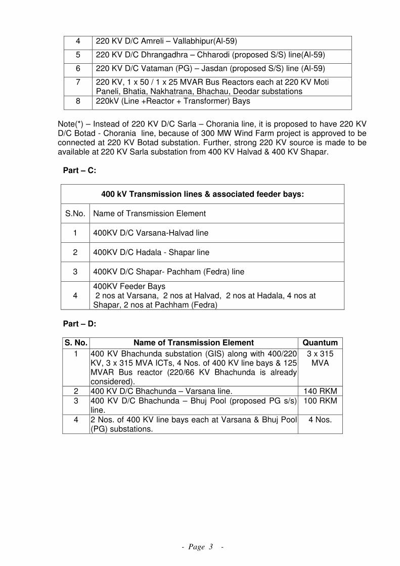
- Page 3 -
4 220 KV D/C Amreli – Vallabhipur(Al-59)
5 220 KV D/C Dhrangadhra – Chharodi (proposed S/S) line(Al-59)
6 220 KV D/C Vataman (PG) – Jasdan (proposed S/S) line (Al-59)
7 220 KV, 1 x 50 / 1 x 25 MVAR Bus Reactors each at 220 KV Moti Paneli, Bhatia, Nakhatrana, Bhachau, Deodar substations
8 220kV (Line +Reactor + Transformer) Bays
Note(*) – Instead of 220 KV D/C Sarla – Chorania line, it is proposed to have 220 KV D/C Botad - Chorania line, because of 300 MW Wind Farm project is approved to be connected at 220 KV Botad substation. Further, strong 220 KV source is made to be available at 220 KV Sarla substation from 400 KV Halvad & 400 KV Shapar.
Part – C:
400 kV Transmission lines & associated feeder bays:
S.No. Name of Transmission Element
1 400KV D/C Varsana-Halvad line
2 400KV D/C Hadala - Shapar line
3 400KV D/C Shapar- Pachham (Fedra) line
4 400KV Feeder Bays 2 nos at Varsana, 2 nos at Halvad, 2 nos at Hadala, 4 nos at Shapar, 2 nos at Pachham (Fedra)
Part – D:
S. No. Name of Transmission Element Quantum
1 400 KV Bhachunda substation (GIS) along with 400/220 KV, 3 x 315 MVA ICTs, 4 Nos. of 400 KV line bays & 125 MVAR Bus reactor (220/66 KV Bhachunda is already considered).
3 x 315 MVA
2 400 KV D/C Bhachunda – Varsana line. 140 RKM 3 400 KV D/C Bhachunda – Bhuj Pool (proposed PG s/s)
line. 100 RKM
4 2 Nos. of 400 KV line bays each at Varsana & Bhuj Pool (PG) substations.
4 Nos.
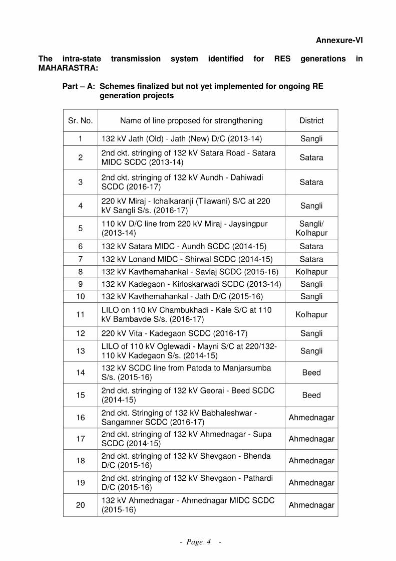
- Page 4 -
Annexure-VI
The intra-state transmission system identified for RES generations in MAHARASTRA:
Part – A: Schemes finalized but not yet implemented for ongoing RE generation projects
Sr. No. Name of line proposed for strengthening District
1 132 kV Jath (Old) - Jath (New) D/C (2013-14) Sangli
2 2nd ckt. stringing of 132 kV Satara Road - Satara MIDC SCDC (2013-14)
Satara
3 2nd ckt. stringing of 132 kV Aundh - Dahiwadi SCDC (2016-17)
Satara
4 220 kV Miraj - Ichalkaranji (Tilawani) S/C at 220 kV Sangli S/s. (2016-17)
Sangli
5 110 kV D/C line from 220 kV Miraj - Jaysingpur (2013-14)
Sangli/ Kolhapur
6 132 kV Satara MIDC - Aundh SCDC (2014-15) Satara
7 132 kV Lonand MIDC - Shirwal SCDC (2014-15) Satara
8 132 kV Kavthemahankal - Savlaj SCDC (2015-16) Kolhapur
9 132 kV Kadegaon - Kirloskarwadi SCDC (2013-14) Sangli
10 132 kV Kavthemahankal - Jath D/C (2015-16) Sangli
11 LILO on 110 kV Chambukhadi - Kale S/C at 110 kV Bambavde S/s. (2016-17)
Kolhapur
12 220 kV Vita - Kadegaon SCDC (2016-17) Sangli
13 LILO of 110 kV Oglewadi - Mayni S/C at 220/132-110 kV Kadegaon S/s. (2014-15)
Sangli
14 132 kV SCDC line from Patoda to Manjarsumba S/s. (2015-16)
Beed
15 2nd ckt. stringing of 132 kV Georai - Beed SCDC (2014-15)
Beed
16 2nd ckt. Stringing of 132 kV Babhaleshwar - Sangamner SCDC (2016-17)
Ahmednagar
17 2nd ckt. stringing of 132 kV Ahmednagar - Supa SCDC (2014-15)
Ahmednagar
18 2nd ckt. stringing of 132 kV Shevgaon - Bhenda D/C (2015-16)
Ahmednagar
19 2nd ckt. stringing of 132 kV Shevgaon - Pathardi D/C (2015-16)
Ahmednagar
20 132 kV Ahmednagar - Ahmednagar MIDC SCDC (2015-16)
Ahmednagar
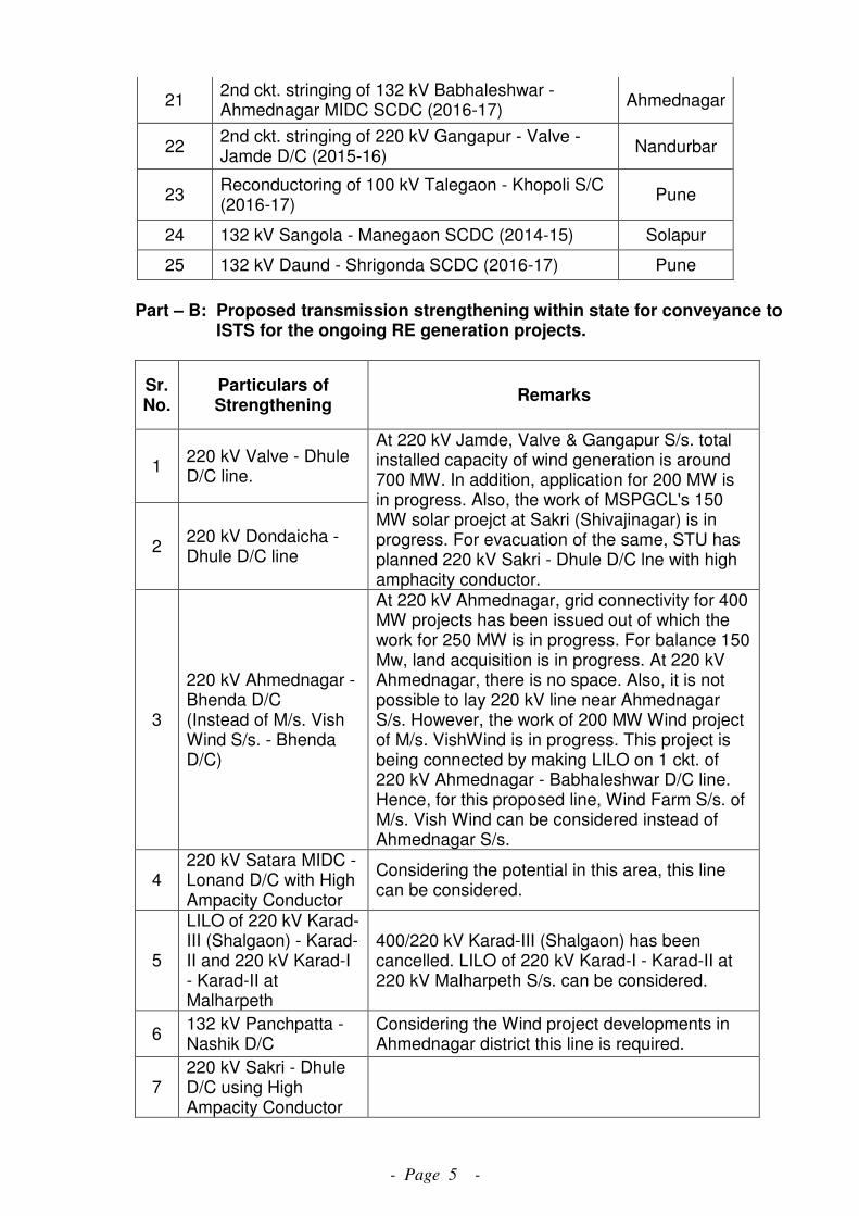
- Page 5 -
21 2nd ckt. stringing of 132 kV Babhaleshwar - Ahmednagar MIDC SCDC (2016-17)
Ahmednagar
22 2nd ckt. stringing of 220 kV Gangapur - Valve - Jamde D/C (2015-16)
Nandurbar
23 Reconductoring of 100 kV Talegaon - Khopoli S/C (2016-17)
Pune
24 132 kV Sangola - Manegaon SCDC (2014-15) Solapur
25 132 kV Daund - Shrigonda SCDC (2016-17) Pune
Part – B: Proposed transmission strengthening within state for conveyance to ISTS for the ongoing RE generation projects.
Sr. No.
Particulars of Strengthening
Remarks
1 220 kV Valve - Dhule D/C line.
2 220 kV Dondaicha - Dhule D/C line
At 220 kV Jamde, Valve & Gangapur S/s. total installed capacity of wind generation is around 700 MW. In addition, application for 200 MW is in progress. Also, the work of MSPGCL's 150 MW solar proejct at Sakri (Shivajinagar) is in progress. For evacuation of the same, STU has planned 220 kV Sakri - Dhule D/C lne with high amphacity conductor.
3
220 kV Ahmednagar - Bhenda D/C (Instead of M/s. Vish Wind S/s. - Bhenda D/C)
At 220 kV Ahmednagar, grid connectivity for 400 MW projects has been issued out of which the work for 250 MW is in progress. For balance 150 Mw, land acquisition is in progress. At 220 kV Ahmednagar, there is no space. Also, it is not possible to lay 220 kV line near Ahmednagar S/s. However, the work of 200 MW Wind project of M/s. VishWind is in progress. This project is being connected by making LILO on 1 ckt. of 220 kV Ahmednagar - Babhaleshwar D/C line. Hence, for this proposed line, Wind Farm S/s. of M/s. Vish Wind can be considered instead of Ahmednagar S/s.
4 220 kV Satara MIDC - Lonand D/C with High Ampacity Conductor
Considering the potential in this area, this line can be considered.
5
LILO of 220 kV Karad-III (Shalgaon) - Karad-II and 220 kV Karad-I - Karad-II at Malharpeth
400/220 kV Karad-III (Shalgaon) has been cancelled. LILO of 220 kV Karad-I - Karad-II at 220 kV Malharpeth S/s. can be considered.
6 132 kV Panchpatta - Nashik D/C
Considering the Wind project developments in Ahmednagar district this line is required.
7 220 kV Sakri - Dhule D/C using High Ampacity Conductor
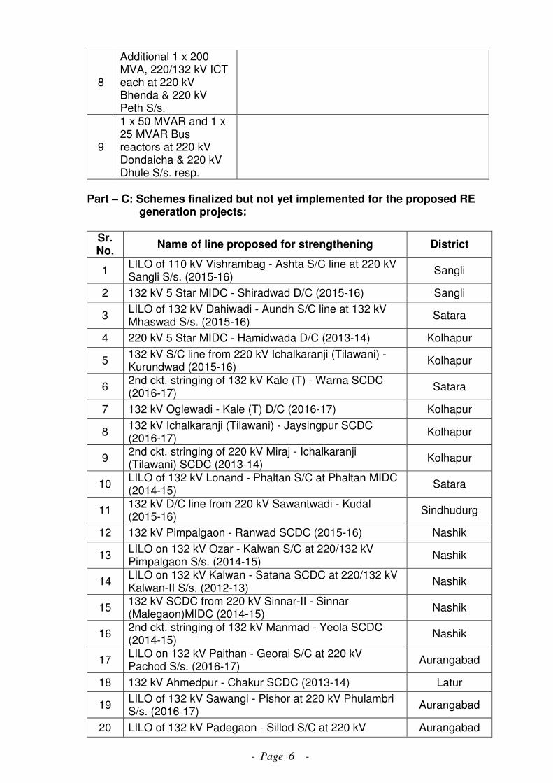
- Page 6 -
8
Additional 1 x 200 MVA, 220/132 kV ICT each at 220 kV Bhenda & 220 kV Peth S/s.
9
1 x 50 MVAR and 1 x 25 MVAR Bus reactors at 220 kV Dondaicha & 220 kV Dhule S/s. resp.
Part – C: Schemes finalized but not yet implemented for the proposed RE generation projects:
Sr. No.
Name of line proposed for strengthening District
1 LILO of 110 kV Vishrambag - Ashta S/C line at 220 kV Sangli S/s. (2015-16)
Sangli
2 132 kV 5 Star MIDC - Shiradwad D/C (2015-16) Sangli
3 LILO of 132 kV Dahiwadi - Aundh S/C line at 132 kV Mhaswad S/s. (2015-16)
Satara
4 220 kV 5 Star MIDC - Hamidwada D/C (2013-14) Kolhapur
5 132 kV S/C line from 220 kV Ichalkaranji (Tilawani) - Kurundwad (2015-16)
Kolhapur
6 2nd ckt. stringing of 132 kV Kale (T) - Warna SCDC (2016-17)
Satara
7 132 kV Oglewadi - Kale (T) D/C (2016-17) Kolhapur
8 132 kV Ichalkaranji (Tilawani) - Jaysingpur SCDC (2016-17)
Kolhapur
9 2nd ckt. stringing of 220 kV Miraj - Ichalkaranji (Tilawani) SCDC (2013-14)
Kolhapur
10 LILO of 132 kV Lonand - Phaltan S/C at Phaltan MIDC (2014-15)
Satara
11 132 kV D/C line from 220 kV Sawantwadi - Kudal (2015-16)
Sindhudurg
12 132 kV Pimpalgaon - Ranwad SCDC (2015-16) Nashik
13 LILO on 132 kV Ozar - Kalwan S/C at 220/132 kV Pimpalgaon S/s. (2014-15)
Nashik
14 LILO on 132 kV Kalwan - Satana SCDC at 220/132 kV Kalwan-II S/s. (2012-13)
Nashik
15 132 kV SCDC from 220 kV Sinnar-II - Sinnar (Malegaon)MIDC (2014-15)
Nashik
16 2nd ckt. stringing of 132 kV Manmad - Yeola SCDC (2014-15)
Nashik
17 LILO on 132 kV Paithan - Georai S/C at 220 kV Pachod S/s. (2016-17)
Aurangabad
18 132 kV Ahmedpur - Chakur SCDC (2013-14) Latur
19 LILO of 132 kV Sawangi - Pishor at 220 kV Phulambri S/s. (2016-17)
Aurangabad
20 LILO of 132 kV Padegaon - Sillod S/C at 220 kV Aurangabad
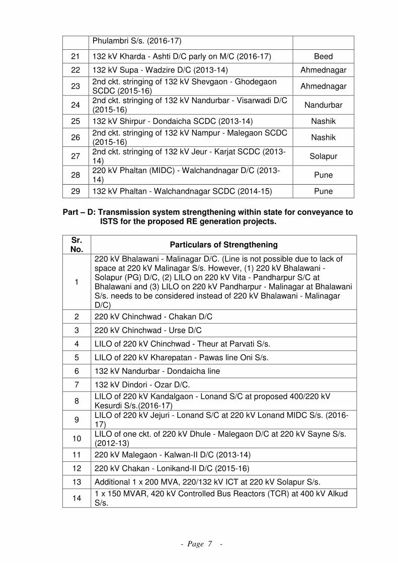
- Page 7 -
Phulambri S/s. (2016-17)
21 132 kV Kharda - Ashti D/C parly on M/C (2016-17) Beed
22 132 kV Supa - Wadzire D/C (2013-14) Ahmednagar
23 2nd ckt. stringing of 132 kV Shevgaon - Ghodegaon SCDC (2015-16)
Ahmednagar
24 2nd ckt. stringing of 132 kV Nandurbar - Visarwadi D/C (2015-16)
Nandurbar
25 132 kV Shirpur - Dondaicha SCDC (2013-14) Nashik
26 2nd ckt. stringing of 132 kV Nampur - Malegaon SCDC (2015-16)
Nashik
27 2nd ckt. stringing of 132 kV Jeur - Karjat SCDC (2013-14)
Solapur
28 220 kV Phaltan (MIDC) - Walchandnagar D/C (2013-14)
Pune
29 132 kV Phaltan - Walchandnagar SCDC (2014-15) Pune
Part – D: Transmission system strengthening within state for conveyance to ISTS for the proposed RE generation projects.
Sr. No.
Particulars of Strengthening
1
220 kV Bhalawani - Malinagar D/C. (Line is not possible due to lack of space at 220 kV Malinagar S/s. However, (1) 220 kV Bhalawani - Solapur (PG) D/C, (2) LILO on 220 kV Vita - Pandharpur S/C at Bhalawani and (3) LILO on 220 kV Pandharpur - Malinagar at Bhalawani S/s. needs to be considered instead of 220 kV Bhalawani - Malinagar D/C)
2 220 kV Chinchwad - Chakan D/C
3 220 kV Chinchwad - Urse D/C
4 LILO of 220 kV Chinchwad - Theur at Parvati S/s.
5 LILO of 220 kV Kharepatan - Pawas line Oni S/s.
6 132 kV Nandurbar - Dondaicha line
7 132 kV Dindori - Ozar D/C.
8 LILO of 220 kV Kandalgaon - Lonand S/C at proposed 400/220 kV Kesurdi S/s.(2016-17)
9 LILO of 220 kV Jejuri - Lonand S/C at 220 kV Lonand MIDC S/s. (2016-17)
10 LILO of one ckt. of 220 kV Dhule - Malegaon D/C at 220 kV Sayne S/s. (2012-13)
11 220 kV Malegaon - Kalwan-II D/C (2013-14)
12 220 kV Chakan - Lonikand-II D/C (2015-16)
13 Additional 1 x 200 MVA, 220/132 kV ICT at 220 kV Solapur S/s.
14 1 x 150 MVAR, 420 kV Controlled Bus Reactors (TCR) at 400 kV Alkud S/s.