> 2 x 3/2, 5/2 and 5/3 > dual spool technology: valves, iso 15407...
TRANSCRIPT

V44/V45, 2 x 3/2, 5/2 & 5/3 Mini ISO Valves
01/17en 5.2.350.01
Our policy is one of continued research and development. We therefore reserve the right to amend, without notice, the specifications given in this document. (2002 - 5036f) © 2015 IMI International s.r.o.
Technical features
> 2 x 3/2, 5/2 and 5/3 valves, ISO 15407-1/VDMA 24 563, Size 26 mm
> Solenoid and pilot actuated
> High performance, compact design
> Flexible sub-base system
> Multipressure system capability
> Dual spool technology: - V44 Glandless spool and sleeve (long life) - V45 Softseal spool (high flow)
> Collected pilot exhaust with internal pilot air supply
> Easy to convert from internal to external pilot supply
> Valve exchange under pressure
Medium:Compressed air, filtered to 40 µm,lubricated or non-lubricatedOperation:V44: Glandless spool valve, solenoid pilot or air pilot actuatedV45: Softseal spool valve, solenoid pilot or air pilot actuated
Flow:V45 Softseal:Function l/min Cv Kv2x3/2 NC 1100 1,12 0,962X3/2 NO 1000 0,98 0,875/2 1200 1,22 1,055/3 1150 1,17 1,00V44 Glandless:Function l/min Cv Kv5/2 900 0,92 0,795/3 900 0,92 0,79Mounting:Sub-base
Operating pressure:See tables for individual detailsMedia/Ambient temperature:-15 ... +50°C (+5 ... 122°F) V44/V45 solenoid and V45 air pilot models -15 ... +80°C (+5 ... 176°F) V44 air pilot modelsAir supply must be dry enough to avoid ice formation attemperatures below +2°C (+35°F).
Materials:Body: die-cast aluminiumSub-bases: aluminium alloySpool and sleeve: hard anodized,Teflon coated, matched aluminium(V44); aluminium alloy spool withHNBR Seals (V45)Plastic parts: POMStatic seals: NBREnd cover and screws: zinc platedSprings: stainless steel

V44/V45, 2 x 3/2, 5/2 & 5/3 Mini ISO Valves
Our policy is one of continued research and development. We therefore reserve the right to amend, without notice, the specifications given in this document. (2002 - 5036f) © 2015 IMI International s.r.o.en 5.2.350.02
01/17
2 x 3/2 Solenoid pilot actuated softseal valvesSymbol Function
2 x 3/2 Actuation/ return
Pilot supply
Pilotexhaust
Operating pressure (bar)
Pilot pressure (bar)
Flow (l/min)
Model
24 1014 10 12
84 8235 1
NC Solenoid/Spring Internal Collected # 3 ... 10 – 1000 V45AA11D-*1)
24 1014 10 12
84 823514 1
NC Solenoid/Spring External Not collected 0 ... 10 1,5 + (0,35 x operating pressure) 1000 V45AA22D-*1)
24 1410 12 10
84 8235 1
NO Solenoid/Spring Internal Collected # 3 ... 10 – 1000 V45AB11D-*1)
24 1410 12 10
84 823514 1
NO Solenoid/Spring External Not collected 0 ... 10 1,5 + (0,35 x operating pressure) 1000 V45AB22D-*1)
24 1014 12 10
84 8235 1
NO/NC Solenoid/Spring Internal Collected # 3 ... 10 – 1000/1100 V45AC11D-*1)
24 1014 12 10
84 823514 1
NO/NC Solenoid/Spring External Not collected 0 ... 10 1,5 + (0,35 x operating pressure) 1000/1100 V45AC22D-*1)
5/2 Solenoid pilot actuated glandless and softseal valvesSymbol Pilot
supply Pilotexhaust
Operator14
Operator12
Operating pressure (bar)
Pilot pressure (bar)
Sealingsystem
Flow (l/min)
Model
24 12
15 3
24 12
15 3
24 12
14
14
14
15 3
Internal Collected # Solenoid Air spring 1 ... 10 – Glandless 900 V44A513D-*1)24
1514 12
14 12
14 12
3 15 3
24
14 12
24
15 3 15 3
24
14 12
24
15 3 15 3
24
14 12
External Not collected Solenoid Air spring -0,9 ... 16 1 ... 10 Glandless 900 V44A523D-*1)24 12
1584 3
24 12
24 12
14
14
14
1584 3
1584 3
Internal Collected # Solenoid Spring 1,6 ... 10 – Glandless 900 V44A517D-*1)
Internal Collected # Solenoid Spring 2 ... 10 – Softseal 1200 V45A517D-*1)24 12
151484 3
24 12
24 12
151484 3
151484 3
External Not collected Solenoid Spring -0,9 ... 16 1,6 ... 10 Glandless 900 V44A527D-*1)
External Not collected Solenoid Spring -0,9 ... 10 2 ... 10 Softseal 1200 V45A527D-*1)24 12
15 3
24 12
15 3
24 12
14
14
14
15 3
84 82
84 82
84 82
Internal Collected # Solenoid Solenoid 2 ... 10 – Glandless 900 V44A511D-*1)
Internal Collected # Solenoid Solenoid 2 ... 10 – Softseal 1200 V45A511D-*1)2 12
12
12
4
24
24
151484 823
151484 823
151484 823
External Not collected Solenoid Solenoid -0,9 ... 16 2 ... 10 Glandless 900 V44A522D-*1)
External Not collected Solenoid Solenoid -0,9 ... 10 2 ... 10 Softseal 1200 V45A522D-*1)2 1214 4
1584 823
1584 823
1584 823
2414 12
14 1224
Internal Collected # Solenoid (priority) Solenoid 2 ... 10 – Glandless 900 V44A591D-*1)2 12
12
12
4
24
24
151484 823
151484 823
151484 823
External Not collected Solenoid (priority) Solenoid -0,9 ... 16 2 ... 10 Glandless 900 V44A592D-*1)
*1) Insert voltage code from tables on page 3 # Pilot exhaust collected and exhausted via port 14 NO = Normally open NC = Normally closed

Our policy is one of continued research and development. We therefore reserve the right to amend, without notice, the specifications given in this document. (2002 - 5036f) © 2015 IMI International s.r.o.
V44/V45, 2 x 3/2, 5/2 & 5/3 Mini ISO Valves
en 5.2.350.0301/17
5/3 Solenoid pilot actuated glandless and softseal valvesSymbol Function Pilot
supply Pilotexhaust
Operator14
Operator12
Operating pressure (bar)
Pilot pressure (bar)
Sealingsystem
Flow (l/min)
Model
24 12
15 3
14
24 12
15 3
14
24 12
15 3
14
24 12
15 3
14
24 12
15 3
14
24 12
15 3
14
APB Internal Collected # Solenoid Solenoid 2 ... 10 – Glandless 900 V44A611D-*2)
APB Internal Collected # Solenoid Solenoid 2,5 ... 10 – Softseal 1150 V45A611D-*2)
24
24
24
1514 12 3
1514 12 3
1514 12 3
APB External Not collected Solenoid Solenoid -0,9 ... 16 2 ... 10 Glandless 900 V44A622D-*2)
APB External Not collected Solenoid Solenoid -0,9 ... 10 2,5 ... 10 Softseal 1150 V45A622D-*2)
24 12
15 3
14
24 12
15 3
14
24 12
15 3
14
COE Internal Collected # Solenoid Solenoid 2 ... 10 – Glandless 900 V44A711D-*2)
COE Internal Collected # Solenoid Solenoid 2,5 ... 10 – Softseal 1150 V45A711D-*2)
24
15 3
24
15 3
24
15 314 12
14 12
14 12
COE External Not collected Solenoid Solenoid -0,9 ... 16 2 ... 10 Glandless 900 V44A722D-*2)
COE External Not collected Solenoid Solenoid -0,9 ... 10 2,5 ... 10 Softseal 1150 V45A722D-*2)
24 12
15 3
14
24 12
15 3
14
24 12
15 3
14
COP Internal Collected # Solenoid Solenoid 2 ... 10 – Glandless 900 V44A811D-*2)
COP Internal Collected # Solenoid Solenoid 2,5 ... 10 – Softseal 1150 V45A811D-*2)
24
15 3
24
15 3
24
15 314 12
14 12
14 12
COP External Not collected Solenoid Solenoid -0,9 ... 16 2 ... 10 Glandless 900 V44A822D-*2)
COP External Not collected Solenoid Solenoid -0,9 ... 10 2,5 ... 10 Softseal 1150 V45A822D-*2)
*2) Insert voltage code from tables below # Pilot exhaust collected and exhausted via port 14 APB = All Ports Blocked COE = Centre Open Exhaust COP = Centre open pressure
Electrical details for solenoid operators Voltage tolerances -10%/+15%
Rating 100 % Continuous duty
Inlet orifice 0,8 mm
Electrical connection 15 mm DIN EN 175301-803 (DIN 43 650) Table C
Manual override Shrouded push button, spring returnConvertible into lockable type with set-up kit,part no. V70532-K00 (see next page)
Protection class IP 65 with sealed plug (ISO 6952) NEMA 4
Materials PPS (body), FPM and NBR (seal)
Voltage codes & spare pilotsVoltage Coil code Current Spare pilot valve
12 V d.c. C312A 1 W VZC7L2C1-C312A
24 V d.c. C313A 1,2 W VZC7L2C1-C313A
24 V 50/60 Hz. C314A 2,1/1,5 VA VZC7L2C1-C314A
48 V 50/60 Hz C316A 2,1/1,5 VA VZC7L2C1-C316A
110 V d.c. C317A 1 W VZC7L2C1-C317A
115 V 50/60 Hz C318A 2,1/1,5 VA VZC7L2C1-C318A
230 V 50/60 Hz C319A 2,1/1,5 VA VZC7L2C1-C319A
Other voltages available on request. Spare pilot valves are delivered with mounting screws.

V44/V45, 2 x 3/2, 5/2 & 5/3 Mini ISO Valves
Our policy is one of continued research and development. We therefore reserve the right to amend, without notice, the specifications given in this document. (2002 - 5036f) © 2015 IMI International s.r.o.en 5.2.350.04
01/17
2 x 3/2 Air pilot actuated softseal valvesSymbol Function
2 x 3/2 Actuation/return 2 x 3/2
Operating pressure (bar)
Pilot pressure (bar)
Sealingsystem
Flow (l/min)
Model
5 1 3
4 210 10
1214
NC Air/Spring 0 ... 10 1,7 + (0,35 x operating pressure) Softseal 1100 V45AA33A-X0020
5 1 3
4 214 12
1010
NO Air/Spring 0 ... 10 1,7 + (0,35 x operating pressure) Softseal 1000 V45AB33A-X0020
5 1 3
4 210 12
1014
NO/NC Air/Spring 0 ... 10 1,7 + (0,35 x operating pressure) Softseal 1000/1100 V45AC33A-X0020
5/2 Air pilot actuated glandless and softseal valvesSymbol Operator
14Operator12
Operating pressure (bar)
Pilot pressure (bar)
Sealingsystem
Flow (l/min)
Model
24
15 3
1214 Air Spring -0,9 ... 16 1,6 ... 16 Glandless 900 V44A537A-X0090
Air Spring -0,9 ... 10 2 ... 10 Softseal 1200 V45A537A-X0090
24
15 3
1214 Air Air -0,9 ... 16 2 ... 16 Glandless 900 V44A533A-X0020
Air Air -0,9 ... 10 2 ... 10 Softseal 1200 V45A533A-X0020
24
15 3
1214 Air (priority) Air -0,9 ... 16 2 ... 16 Glandless 900 V44A533A-X0070
5/3 Air pilot actuated glandless and softseal valvesSymbol Function Operator
14Operator12
Operating pressure (bar)
Pilot pressure (bar)
Sealingsystem
Flow (l/min)
Model
4 2
5 1 3
1214 APB Air Air -0,9 ... 16 2 ... 16 Glandless 900 V44A633A-X0020
APB Air Air -0,9 ... 10 2,5 ... 10 Softseal 1150 V45A633A-X0020
4 2
5 1 3
1214 COE Air Air -0,9 ... 16 2 ... 16 Glandless 900 V44A733A-X0020
COE Air Air -0,9 ... 10 2,5 ... 10 Softseal 1150 V45A733A-X0020
4 2
5 1 3
1214 COP Air Air -0,9 ... 16 2 ... 16 Glandless 900 V44A833A-X0020
COP Air Air -0,9 ... 10 2,5 ... 10 Softseal 1150 V45A833A-X0020
Valve function: NO = Normally open, NC = Normally closed APB = All Ports Blocked COE = Centre Open Exhaust COP = Centre Open Pressure

Our policy is one of continued research and development. We therefore reserve the right to amend, without notice, the specifications given in this document. (2002 - 5036f) © 2015 IMI International s.r.o.
V44/V45, 2 x 3/2, 5/2 & 5/3 Mini ISO Valves
en 5.2.350.0501/17
Accessories DIN EN 50 022 rail (1 m) DIN-rail mounting kit Blanking disc to
modular sub-baseManual overrideset-up kit
Blanking plate for unused station
Page 11
Transition plateV40/V41 » V44/V45
Page 11
V10009-C00 (35 x 7,5 mm) V70531-KA0 V70522-K00 (Ports 1,3,5)) V70532-K00 V70500-KA0 V70436-K00
V10592-C01 (35 x 15 mm) V70523-K00 (Ports 12 & 14) V70436-B00 *3)
*3) With supply and exhaust portsg
Sandwich platesIntermediate supply/ exhaust manifole
Page 10
Single valve shut-off plate
Page 10
Single pressure regulator plate
Page 12 & 13
Double pressure regulator plate
Page 13
Flow regulator plate
Page 10
Sandwich plate withadditional pressure port 1
Page 11
V70529-BA0 (G1/4) V70530-KA0 (Port 1 blocked) V70527-KA1 (Port 1 reg.) V70527-KA4 (Ports 2+4 reg.) V70528-KA0 (Ports 3+5 reg.) V70535-BA0 (G1/4)
V70527-KA2 (Port 2 reg.) V70535-RA0 (1/4 NPTF)
V70527-KA3 (Port 4 reg.)
Sub-bases and end platesSingle station sub-base
Page 9
Single station modular sub-base, side ported
Page 7
Single station modular sub-base, bottom ported
Page 7
End plate kit
Page 7
Fixed length sub-base
Page 9
V70501-BAB (G1/4) V70525-*AF *4) V70525-BAE (G1/4) *4) V70524-CAC (G3/8) V705**-BA0 (G1/4)
V70501-RAB (1/4 NPTF) V70526-*AF *5) V70526-BAE (G1/4) *5) V70524-SAC (3/8 NPTF) V705**-RAO (1/4 NPTF)
* = Insert code for port type, see on page 7 ** = Insert number of valve stations in sub-base assemblies, see page 8 *4) Without pilot ports *5) With pilot ports
Connector plug - ordered separately15 mm DIN EN 175301-803 (DIN 43 650) Table C
V10027-D00250 V AC/300 V DC.

82
35
6,4 M4
39
19
26,7
130 1
82
35
6,4 M4
19
26,7
37,4
102 1
82
35
6,4 M4
*
19
26,7
130
108
1
1
130
39
35
6,4 M4
19
26,7
39
35
6,4 M4
19
26,7
37,4
102
V44/V45, 2 x 3/2, 5/2 & 5/3 Mini ISO Valves
Our policy is one of continued research and development. We therefore reserve the right to amend, without notice, the specifications given in this document. (2002 - 5036f) © 2015 IMI International s.r.o.en 5.2.350.06
01/17
Valve dimensions
1 Manual override
V44A5*3D-C3***5/2 Single solenoid pilot valve Air spring return
V44A5*7D-C3*** & V45A5*7D-C3***5/2 Single solenoid pilot valveMechanical spring return
V44A5**D-C3*** & V45A5**D-C3*** 5/2 Double solenoid pilot valve V44A***D-C3*** & V45A***D-C3*** 2x3/2 + 5/3 Double solenoid pilot valve
Dimensions in mm Projection/First angle
V44A537A-X00*0 & V45A537A-X00*05/2 Single air pilot valve
V44A*33A-X00*0 & V45A*33A-X00*02 x 3/2, 5/2 + 5/3 Double air pilot valve

12 12 12
2 2 2
4 44
14 14 14
14 12
31
5
4 2
4 2
4 2
17,5
32
53
D
B
A CC
17,6
1139,549
,5
5
17
12
49,4
Y
4,5
78
4,59,5 27
27*N
x 2
7,1
355
,5
90,5
138
18,5
43,5
68
90
18
35
69
2331
46,5
* N = Number of stations
M5
M5
1 2
Our policy is one of continued research and development. We therefore reserve the right to amend, without notice, the specifications given in this document. (2002 - 5036f) © 2015 IMI International s.r.o.
V44/V45, 2 x 3/2, 5/2 & 5/3 Mini ISO Valves
en 5.2.350.0701/17
1 Right hand side 2 Left hand side
Dimensions in mm Projection/First angle
Modular sub-bases parts for DIN rail or surface mountingBottom ported sub-base
Bottom and side ported sub-base
View Y
Side ported sub-base
V44/V45, 2 x 3/2, 5/2 & 5/3 Mini ISO Valves
Our policy is one of continued research and development. We therefore reserve the right to amend, without notice, the specifications given in this document. (2002 - 5036f) © 2015 IMI International s.r.o.en 5.2.350.08
01/17
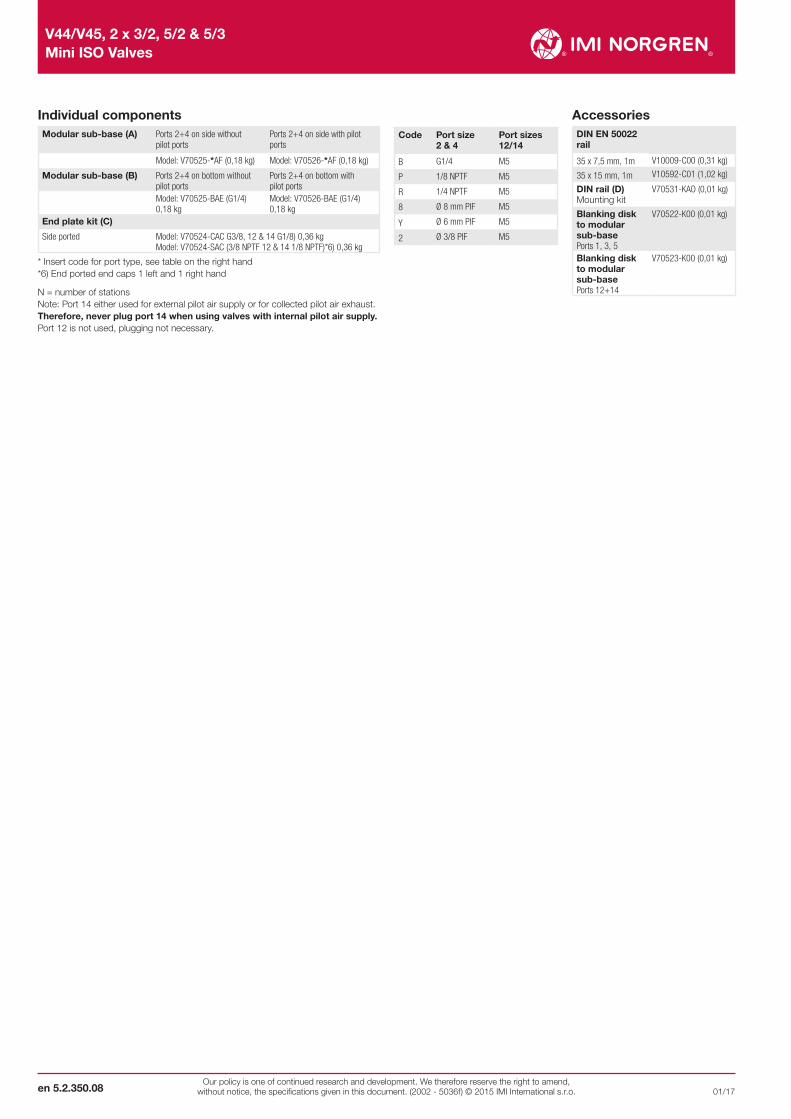
AccessoriesDIN EN 50022 rail
35 x 7,5 mm, 1m V10009-C00 (0,31 kg)
35 x 15 mm, 1m V10592-C01 (1,02 kg)
DIN rail (D) Mounting kit
V70531-KAO (0,01 kg)
Blanking disk to modular sub-basePorts 1, 3, 5
V70522-K00 (0,01 kg)
Blanking disk to modular sub-base Ports 12+14
V70523-K00 (0,01 kg)
Code Port size 2 & 4
Port sizes 12/14
B G1/4 M5
P 1/8 NPTF M5
R 1/4 NPTF M5
8 Ø 8 mm PIF M5
Y Ø 6 mm PIF M5
2 Ø 3/8 PIF M5
Individual componentsModular sub-base (A) Ports 2+4 on side without
pilot portsPorts 2+4 on side with pilot ports
Model: V70525-*AF (0,18 kg) Model: V70526-*AF (0,18 kg)
Modular sub-base (B) Ports 2+4 on bottom without pilot ports
Ports 2+4 on bottom with pilot ports
Model: V70525-BAE (G1/4) 0,18 kg
Model: V70526-BAE (G1/4) 0,18 kg
End plate kit (C)
Side ported Model: V70524-CAC G3/8, 12 & 14 G1/8) 0,36 kg Model: V70524-SAC (3/8 NPTF 12 & 14 1/8 NPTF)*6) 0,36 kg
* Insert code for port type, see table on the right hand *6) End ported end caps 1 left and 1 right hand
N = number of stations Note: Port 14 either used for external pilot air supply or for collected pilot air exhaust.Therefore, never plug port 14 when using valves with internal pilot air supply. Port 12 is not used, plugging not necessary.

3
1
5
14
4 2
12
21,8 21,8
A
10 18
5,5 1
5,5
1927 542
M4
80,5
92
80,5
55
225,5
612
28
13,5
21
69
M5
5
1
3
42
42
24,6
24 27
5,5
17
32
11,5
11,5
37,5
63,5
25,4
24,8
B
A
7,5
X
5,9
10
Our policy is one of continued research and development. We therefore reserve the right to amend, without notice, the specifications given in this document. (2002 - 5036f) © 2015 IMI International s.r.o.
V44/V45, 2 x 3/2, 5/2 & 5/3 Mini ISO Valves
en 5.2.350.0901/17
Dimensions in mm Projection/First angle
Single station sub-base – side ported with pilot ports
Port size A Model
G1/4 side ported with pilot ports 0,11 kg V70501-BAB
NPTF1/4 side ported with pilot ports 0,24 kg V70501-RAB
Note: Pilot ports = M5
Fixed length sub-base - bottom ported
Number of stations
A B Weight(kg)
Model
2 83 68 0,4 V70502-xAO
4 137 122 0,65 V70504-xAO
6 191 176 0,91 V70506-xAO
8 245 230 1,15 V70508-xAO
10 299 284 1,41 V70510-xAO
12 353 338 1,66 V70512-xAO
x = Insert port type from table
Code Ports 2 & 4
Ports 1, 3 & 5
B G1/4 G3/8
R 1/4NPTF 3/8 NPTF
Note: This sub-base is suitable for solenoid pilot actuated valves with internal pilot air supply only

3 51
M4
19 26
44
1316
266
77
G1/411
63
33
33
M4
21,5
6,5
8
13,5
19 27
97
10,5
8M4
21,5
6,5
19 27
93,5
120,5
136,5
500400300200100
1000900
12001100
800700600
00 1 2 3 4 5 6 7 8 9 10 11 12 13 14
V44/V45, 2 x 3/2, 5/2 & 5/3 Mini ISO Valves
Our policy is one of continued research and development. We therefore reserve the right to amend, without notice, the specifications given in this document. (2002 - 5036f) © 2015 IMI International s.r.o.en 5.2.350.10
01/17
Dimensions in mm Projection/First angle
Intermediate supply/exhaust manifold Single valve shut-off plate
Symbol Description Model
513
4 2 Single shut-off plate supplied with gasket(0,13 kg)
V70530-KAO
Allows individual exchange of valve, while valve island is pressurised by port 1. Note: Flow restricted to max. 500 l/min.
Flow regulator plate
Port size A Model
G1/4 (0,12 kg) V70529-BAO
Flow characteristics for pressure regulator plates Dual regulation of exhaust ports 3 & 5
Flow: Port 1 > 2 & 1> 4: remains unchangedFlow measured at 6 bar inlet, pressure drop 1 barEx
haus
t flow
(por
ts 3
+5) [
l/min
]
Number of turns from closed
Port size 5
Port size 3
Symbol Description Model 4 2
5 31
Flow regulator supplied with gasket (0,17 kg) V70528-KAO

22,5
V40/41
V40/41
5 1 3
V44/45V44/45
3 x G1/4
39,5
65 27 3,5
55
90
17,5
10
,5
73,5
33
M4
21,5
6,5
9,5
13,5
1
19 26,8
3,9
79
16,8
6
26,7
19
M4
66
Our policy is one of continued research and development. We therefore reserve the right to amend, without notice, the specifications given in this document. (2002 - 5036f) © 2015 IMI International s.r.o.
V44/V45, 2 x 3/2, 5/2 & 5/3 Mini ISO Valves
en 5.2.350.1101/17
Dimensions in mm Projection/First angle
Sandwich plate with additional pressure port 1
Transition plate #18 mm > #26 mm
Symbol Description Model
4 2
5 31 1e
Sandwich plate with additional port 1 G1/4, supplied with gasket (0,12 kg)
V70535-BAO
Sandwich plate with additional port 1 G1/4, supplied with gasket (0,12 kg)
V70535-RAO
Description Model
Transition plate V40/V41 » V44/V45Without port 1/3/5
V70436-K0O
Transition plate V40/V41 » V44/V45with supply/exhaust ports G1/4
V70436-B00
Blanking plate
Description Model
Blanking plate for blocking of unused stations(supplied with gasket, 0,03 kg)
V70500-KAO

89,5
162
73,5
388,
5
26,5
Ø 26
Ø 2
2,5
19
20
2,5
qn = 20 L / min
bar
2,4
2,2
2,0
1,8
1,6
1,5
3 4 5 6 7 8 9 10180
qn l / min
p1 = 10 bar
8
66,3
5,3
4
2
0 360 540 720 900
bar
V44/V45, 2 x 3/2, 5/2 & 5/3 Mini ISO Valves
Our policy is one of continued research and development. We therefore reserve the right to amend, without notice, the specifications given in this document. (2002 - 5036f) © 2015 IMI International s.r.o.en 5.2.350.12
01/17
Dimensions in mm Projection/First angle
Pressure regulator plates V70527-KA1 & V70527-KA2 (including gauges)
Sandwich plates Pressure regulator sandwich platesSymbol Model Description
14 5 4 1 2 3 12
V70527-KA1 Regulation of port 1, regulator on side 12
3 1214 2145
V70527-KA2 Regulation of port 2,regulator on side 1
Symbol Model Description
3 1214 2145
V70527-KA3 egulation of port 4,regulator on side 14
3 1214 2145
V70527-KA4 Regulation of ports 2+4
Flow characteristics for pressure regulator plates
Reg
ulat
ed p
ress
ure
(bar
)
Hysteresis
Inlet pressure
Au
sgan
gsd
ruck
Starting point

89,5
162
73,5
388,
5
26,5
Ø 26
Ø 2
2,5
19
179
243
Ø 2
2,5
73,5
388,
5
26,5
Ø 26
19
Our policy is one of continued research and development. We therefore reserve the right to amend, without notice, the specifications given in this document. (2002 - 5036f) © 2015 IMI International s.r.o.
V44/V45, 2 x 3/2, 5/2 & 5/3 Mini ISO Valves
en 5.2.350.1301/17
Dimensions in mm Projection/First angle
Pressure regulator plate V70527-KA3 (including gauges)
Pressure regulator plate V70527-KA4 (including gauges)
Warning
These products are intended for use in industrial compressed air systems only. Do not use these products where pressures and temperatures can exceed those listed under »Technical features/data«. Before using these products with fluids other than those specified, for non-industrial applications, life-support systems or other applications not within published specifications, consult IMI Precision Engineering, IMI International s.r.o.
Through misuse, age, or malfunction, components used in fluid power systems can fail in various modes. The system designer is warned to consider the failure modes of all component parts used in fluid power systems and to provide adequate safeguards to prevent personal injury or damage to equipment in the event of such failure. System designers must provide a warning to end users in the system instructional manual if protection against a failure mode cannot be adequately provided. System designers and end users are cautioned to review specific warnings found in instruction sheets packed and shipped with these products.
EN - Englisch