© 2003 by american institute of steel construction, inc...
TRANSCRIPT

© 2003 by American Institute of Steel Construction, Inc. All rights reserved.This publication or any part thereof must not be reproduced in any form without permission of the publisher.

16Steel Design Guide Series
Thomas M. Murray, P.E., Ph.D.Montague Betts Professor of Structural Steel DesignCharles E. Via Department of Civil EngineeringVirginia Polytechnic Institute and State UniversityBlacksburg, Virginia
W. Lee Shoemaker, P.E., Ph.D.Director of Research & EngineeringMetal Building Manufacturers AssociationCleveland, Ohio
A M E R I C A N I N S T I T U T E O F S T E E L C O N S T RU C T I O N
Flush and Extended Multiple-Row
Moment End-Plate Connections

Copyright 2002
by
American Institute of Steel Construction, Inc.
All rights reserved. This book or any part thereofmust not be reproduced in any form without the
written permission of the publisher.
The information presented in this publication has been prepared in accordance with rec-ognized engineering principles and is for general information only. While it is believedto be accurate, this information should not be used or relied upon for any specific appli-cation without competent professional examination and verification of its accuracy,suitablility, and applicability by a licensed professional engineer, designer, or architect.The publication of the material contained herein is not intended as a representationor warranty on the part of the American Institute of Steel Construction or of any otherperson named herein, that this information is suitable for any general or particular useor of freedom from infringement of any patent or patents. Anyone making use of thisinformation assumes all liability arising from such use.
Caution must be exercised when relying upon other specifications and codes developedby other bodies and incorporated by reference herein since such material may be mod-ified or amended from time to time subsequent to the printing of this edition. TheInstitute bears no responsibility for such material other than to refer to it and incorporateit by reference at the time of the initial publication of this edition.
Printed in the United States of America
Second Printing: October 2003
Published by the American Institute of Steel Construction, Inc.At One East Wacker Drive, Suite 3100, Chicago, IL 60601
The co-sponsorship of this publication by the Metal BuildingManufacturers Association is gratefully acknowledged.
© 2003 by American Institute of Steel Construction, Inc. All rights reserved.This publication or any part thereof must not be reproduced in any form without permission of the publisher.

ACKNOWLEDGMENTS
Design procedures in this Guide are primarily based on research conducted at the Uni-versity of Oklahoma and at Virginia Polytechnic Institute. The research was sponsored by the Metal Building Manufacturers Association (MBMA), the American Institute of Steel Construction (AISC), and Star Building Systems. MBMA and AISC member com-panies provided test specimens. The work of former Oklahoma and Virginia Tech graduate students, Ramzi Srouji, David M. Hendrick, Scott J. Morrison, Mary Sue Abel, and Jeffrey T. Borgsmiller, made this Guide possible. Virginia Tech graduate students Emmett A. Sumner III and Timothy R. Mays contributed valuable work to update the yield line mechanisms used and with final checking of the design procedures. The assis-tance of Patrick Toney, Star Building Systems, in developing the final manuscript is gratefully appreciated and acknowledged.
© 2003 by American Institute of Steel Construction, Inc. All rights reserved.This publication or any part thereof must not be reproduced in any form without permission of the publisher.

© 2003 by American Institute of Steel Construction, Inc. All rights reserved.This publication or any part thereof must not be reproduced in any form without permission of the publisher.

TABLE OF CONTENTS 1. Uses and Classification of Moment End-Plate
Connections................................................................1
1.1 Introduction..........................................................1
1.2 Background ..........................................................3 1.2.1 Design Procedures for Moment End-
Plates with Fully Tightened Bolts .............3 1.2.2 Design Procedures for Moment End-
Plates with Snug Tight Bolts .....................5 1.2.3 Finite Element Analysis of Moment
End-Plates..................................................5 1.2.4 Performance of Moment End-Plate
Connections for Seismic Loading .............6
2. Design Procedures .....................................................7
2.1 Introduction..........................................................7
2.2 Yield-Line Theory and Mechanics.......................7
2.3 Bolt Force Predictions..........................................7
2.4 Moment-Rotation Relationships ..........................8
2.5 Design Procedures................................................9 2.5.1 Design Procedure 1 .................................10 2.5.2 Design Procedure 2 .................................11 2.5.3 Additional Assumptions and
Conditions ...............................................12
2.6 Limit States Check List ......................................13
3. Flush End-Plate Design...........................................17
3.1 Design Equations, Limitations, and Definitions........................................................17
3.1.1 Design Equations.....................................17 3.1.2 Limitations...............................................17 3.1.3 Definitions ...............................................17
3.2 Design Examples................................................22 3.2.1 Two-Bolt Flush Unstiffened Moment
End-Plate Connection..............................22 3.2.2 Four-Bolt Flush Unstiffened Moment
End-Plate Connection..............................23
3.2.3 Four-Bolt Flush Stiffened Moment End-Plate Connection (Stiffener Between Bolt Rows)................................25
3.2.4 Four-Bolt Flush Stiffened Moment End-Plate Connection (Stiffener Outside Bolt Rows) .................................27
4. Extended End-Plate Design ....................................31
4.1 Design Equations, Limitations, and Definitions..........................................................31 4.1.1 Design Equations.....................................31 4.1.2 Limitations...............................................31 4.1.3 Definitions ...............................................31
4.2 Design Examples................................................39 4.2.1 Four-Bolt Extended Unstiffened
Moment End-Plate Connection ...............39 4.2.2 Four-Bolt Extended Stiffened
Moment End-Plate Connection ...............41 4.2.3 Multiple Row 1/2 Extended
Unstiffened Moment End-Plate Connection ..............................................43
4.2.4 Multiple Row 1/3 Extended Unstiffened Moment End-Plate Connection ..............................................45
4.2.5 Multiple Row 1/3 Extended Stiffened Moment End-Plate Connection ...............47
5. Gable Frame Panel Zone Design............................51
5.1 Introduction........................................................51
5.2 LRFD Rules and Example Calculations.............52 5.2.1 LRFD Rules.............................................52 5.2.2 LRFD Example........................................52
5.3 Allowable Stress Design Rules and Example Calculations........................................................54 5.3.1 Allowable Stress Design Rules................54 5.3.2 ASD Example Calculations .....................55
REFERENCES .............................................................57
APPENDIX A: Nomenclature.......................................61
APPENDIX B: Bolted End-Plate Connection Analysis Flowchart .............................................63
© 2003 by American Institute of Steel Construction, Inc. All rights reserved.This publication or any part thereof must not be reproduced in any form without permission of the publisher.

© 2003 by American Institute of Steel Construction, Inc. All rights reserved.This publication or any part thereof must not be reproduced in any form without permission of the publisher.

1
Chapter 1 USE AND CLASSIFICATION OF MOMENT END-PLATE CONNECTIONS1.1 Introduction The low-rise metal building industry has pioneered the use of moment end-plate connections in the United States. These bolted connections are used between rafters and columns and to connect two rafter segments in typical gable frames as shown in Figures 1-1 and 1-2. Hence, built-up shapes used in the metal building industry are exclusively used in the examples; however, the design procedures also apply to hot-rolled shapes of comparable dimensions to the tested parameter ranges (i.e. Tables 3-6 and 4-7).
Rigid frame or continuous frame construction, desig-nated Type FR in the American Institute of Steel Con-struction (AISC) Load and Resistance Factor Design (LRFD) Specification or Type 1 in the AISC Allowable Stress Design (ASD) Specification, is usually assumed for
the design of the frames. The moment end-plate connec-tion is one of three fully restrained moment connections, as defined in the AISC Manual of Steel Construction,Load & Resistance Factor Design, 2nd Ed. (1994), that can be used for FR (or Type 1) beam-to-column connec-tions.
A typical end-plate moment connection is composed of a steel plate welded to the end of a beam section with attachment to an adjacent member using rows of high-strength bolts. End-plate moment connections are classi-fied as either flush or extended, with or without stiffeners, and further classified depending on the number of bolts at the tension flange. Depending on the direction of the moment and whether the connection will see a moment reversal, the bolted end-plate may be designed to carry
M M
Tension Zone
(a) Beam-to-Beam Connection
Tension Zone
M
M
(b) Beam-to-Column Connection
Figure 1-1 Typical uses of end-plate moment connections (flush).
Tension Zone
Tension Zone
MM
M
M
Tension Zone
M
M
Tension Zone
M M
(a) Beam-to-Beam Connection
(b) Beam-to-Column Connection
Figure 1-2 Typical uses of end-plate moment connections (extended).
Tension Zone
Tension Zone
MM
M
M
© 2003 by American Institute of Steel Construction, Inc. All rights reserved.This publication or any part thereof must not be reproduced in any form without permission of the publisher.

2
tension at the top or bottom, or both. This could result in a design with a combination of configurations such as a flush end-plate at the compression side and an extended end-plate at the tension side.
A flush connection is detailed such that the end-plate does not appreciably extend beyond the beam flanges with all bolts located between the beam flanges. An ex-tended end-plate is one that extends beyond the tension flange a sufficient distance to allow the location of bolts other than between the beam flanges. Flush end-plate connections are typically used in frames subject to light lateral loads or near inflection points of gable frames. Extended end-plates are typically used for beam-to-column moment connections. However, flush end-plates are sometimes used for beam-to-column moment connec-tions when a plate extension would interfere with other members or the roof deck.
Four flush and five extended end-plate connections are within the scope of this Guide. The four types of flush
end-plate configurations are shown in Figure 1-3. Figures 1-3a and 1-3b show unstiffened flush end-plate connec-tions with two and four bolts near the tension flange. Fig-ures 1-3c and 1-3d show stiffened flush end-plate connec-tions with four bolts near the tension flange. In Figure 1-3c a web stiffener plate is located on both sides of the web between the two tension bolt rows, while in Figure 1-3d the web stiffener plates are located inside the two ten-sion bolt rows. For both connections, the stiffener plates are welded to both the end-plate and the beam web.
The five extended end-plate configurations are shown in Figure 1-4. Figure 1-4a shows an extended, unstiffened end-plate connection with four bolts at the tension flange and Figure 1-4b shows the same connection with an end-plate to beam flange stiffener. The unstiffened connection shown in Figure 1-4a is probably the most commonly used end-plate configuration. Three multiple row ex-tended end-plate configurations are shown in Figures 1-4c, 1-4d and 1-4e. These configurations have one row of
(b) Four-Bolt Unstiffened
(c) Four-Bolt Stiffened with Web Gusset Plate Between the Tension Bolts
(d) Four-Bolt Stiffened with Web Gusset Plate Between the Tension Bolts
Figure 1-3 Flush end-plate connections.
© 2003 by American Institute of Steel Construction, Inc. All rights reserved.This publication or any part thereof must not be reproduced in any form without permission of the publisher.

3
bolts outside the tension flange and either two or three rows of bolts inside the tension flange. They are identi-fied with the notation 1/n, where “n” is the number of bolt rows inside the tension flange. The connection shown in Figure 1-4c is designated as the unstiffened 1/2 configu-ration, while the connections shown in Figures 1-4d and 1-4e are designated as unstiffened and stiffened 1/3 con-figurations, respectively.
The primary purpose of this Guide is to provide a con-venient source of design procedures for the nine con-nections shown in Figures 1-3 and 1-4. In addition, de-sign considerations for the “knee area” of rigid frames are discussed.
The end-plate connection design procedures presented here use yield-line techniques for the determination of end-plate thickness and include the prediction of tension bolt forces. The bolt force equations were developed be-cause prying forces are important and must be considered in bolt force calculations. Moment-rotation considerations are also included in the design procedures. Chapter 2 con-tains the general design procedures. Design procedures for flush connections are found in Chapter 3 and for ex-tended connections in Chapter 4. Knee area design crite-ria are given in Chapter 5. The analysis of bolted end-plate connections is covered in Appendix B. Both Allow-able Stress Design (ASD) and Load and Resistance Fac-tor Design (LRFD) procedures are discussed and illus-trated throughout the Guide.
1.2 Background1.2.1 Design Procedures for Moment End-Plates With Fully Tensioned Bolts The end-plate moment connection saw its first application in the 1960’s, stemming from research in the 1950’s. The connection was not a new concept but more of an evolu-tion of the much-used split tee connection (Disque 1962). The early designs usually resulted in thick end-plates and large bolt diameters due mainly to simplified design as-sumptions and analyses of the connection. The connec-tion slowly gained acceptance and was included in the AISC Manual of Steel Construction, 7th Ed. (1970) due in large part to the efforts of Douty and McGuire (1965). Their methods used assumptions concerning bolt forces due to prying action and simple statics resulting from earlier) tee-stub analysis. As discussed by Griffiths (1984), this first attempt to standardize the design resulted in a very conservative connection. It did spur further in-terest as seen by various studies in the early 1970's. Kato and McGuire (1973) and Nair, et al. (1974) continued the tee-stub concept to account for prying action. As before, the procedures continued to produce a design with thick plates and large bolt diameters. Based on this research and that of Agerskov (1976, 1977), Granstrom (1980) continued with a simple design of tee-hangers. His result-ing design produced thinner plates and smaller diameter bolts than before, but he did not consider the effects of prying action.
(a) Four-Bolt Unstiffened (b) Four-Bolt Stiffened (c) Multiple Row 1/2 Unstiffened
(d) Multiple Row 1/3 Unstiffened (e) Multiple Row 1/3 Stiffened
Figure 1-4 Extended end-plate connections.
© 2003 by American Institute of Steel Construction, Inc. All rights reserved.This publication or any part thereof must not be reproduced in any form without permission of the publisher.

4
Packer and Morris (1977) were among the first to use yield-line analysis. Using the tee-stub model for the end-plate, they developed a yield line analysis of the column flanges. Mann and Morris (1979) extended these initial efforts in the use of yield line analysis. From review of previous research, they surmised that the end-plate must exhibit plastic deformation and the formation of yield lines when near its capacity. Their proposed design pro-cedures determined plate thickness and bolt diameter as well as adequacy checks for the supporting column.
Krishnamurthy (1978) broke from the traditional analysis and derived empirical relationships based on statistical analysis of finite element results. Formulas de-rived for end-plate thickness provided thinner plates than previously obtained. He explained the prying force as a pressure bulb formed under the bolt head due to the ten-sioning of the bolts. The location of the pressure bulb varied, depending on the level of the flange force in the beam. As the force increases, the pressure bulb shifts to-wards the edge of the plate. The design procedures in the current editions of the AISC Manual of Steel Constructionare in part based on his basic work.
Kennedy, et al. (1981) refined the tee-stub analysis to include the prediction of prying forces utilizing yield line theory and the formation of plastic hinges. They catego-rized the tee-stub flange behavior on three levels. First, at low loads, there is the absence of any hinge formation in the flange plate and the plate is said to be “thick,” with no prying action present. Second, upon the formation of a hinge caused by yielding of the flange at the tee-stem, the plate is said to be “intermediate.” Some prying action during the intermediate case is realized and adds to the bolt forces. The third stage, “thin,” is determined when the second plastic hinge forms at the bolt line. At this load level, the prying action is considered to be at its maxi-mum.
Srouji, et al. (1983a) used yield-line analysis and the Kennedy method of bolt force predictions in the first of many studies conducted by Professor T. M. Murray at the University of Oklahoma and Virginia Polytechnic Insti-tute aimed at moment end-plate design unification. They presented yield-line design methodology for a two-bolt flush, unstiffened end-plate configuration (Figure 1-3a). A later report by Srouji, et al. (1983b) extended the work to other configurations including the four-bolt flush, un-stiffened connection (Figure 1-3b). Bolt force predictions including prying action were produced for the two-bolt and four-bolt flush, unstiffened configurations. An ex-perimental investigation was conducted to verify the end-plate and bolt force predictions. It was concluded that yield-line analysis and a modified Kennedy method are accurate methods for predicting end-plate strength and bolt forces.
Hendrick, et al. (1984) continued Srouji's work by analyzing and testing two different four-bolt flush stiff-ened end-plate configurations: those with the stiffener
between the tension bolt rows (Figure 1-3c), and those with the stiffener inside the tension bolt rows (Figure 1-3d). Analysis included the use of yield-line theory for end-plate strength predictions and the modified Kennedy approach for bolt force predictions. Analytical predictions for end-plate strength using yield-line theory and bolt forces using the modified Kennedy approach correlated well with data. However, an improvement in the method for determining the internal work for the yield line analy-sis was presented by Hendrick, et al. (1985) for the con-nection with the stiffener outside the tension bolt rows.
It was also determined by Hendrick, et al. (1985) that the connections behaved as a Type 1 or FR connection up to a certain percentage of the failure moment of the end-plate at which point the moment-rotation curve softens. An analysis of the moment-rotation curves for the beam specimens tested indicated that a conservative value of 80% of the failure moment was a reasonable limit to en-sure Type 1 or FR behavior.
Four-bolt extended stiffened (Figure 1-4b) and multi-ple row extended unstiffened 1/3 (Figure 1-4d) configura-tions were tested and analyzed by Morrison, et al. (1985, 1986). Analysis procedures included the use of yield-line theory and modified Kennedy bolt force predictions. Modifications to the Kennedy method were necessary for determining the distribution of the applied flange force between the outer and inner bolts in the extended end-plate configurations. Morrison's modification factors came directly from the experimental results of six tests of four-bolt extended stiffened connections (Figure 1-4b) and six tests of multiple row extended unstiffened 1/3 connections (Figure 1-4d). It was concluded from these tests that the outer bolts do not exhibit prying action, and therefore carry the majority of the applied flange force. It was additionally concluded that the four-bolt extended stiffened and multiple row extended unstiffened 1/3 con-figurations contain adequate stiffness to be classified as Type 1 or FR connections.
Abel and Murray (1992b) added a final configuration to the unification of moment end-plate design: the four-bolt extended unstiffened configuration (Figure 1-4a). Analysis was conducted using the same yield-line analy-sis and modified Kennedy method. Four full-scale tests were conducted to verify the predictions. It was con-cluded that the outer and inner rows of bolts each carry half of the applied flange force, however, when the bolt force prediction controls in the analysis, no prying action exists in the outer bolts. As with the other configurations, the four-bolt extended unstiffened moment end-plate connection contains adequate moment-rotation stiffness to be classified as a Type 1 or FR connection.
Proprietary testing was carried out on the multiple row extended unstiffened 1/2 configuration of Figure 1-4c and the multiple row extended stiffened 1/3 configuration of Figure 1-4e as reported in Abel and Murray (1992a) and SEI (1984). The inclusion of these configurations in this
© 2003 by American Institute of Steel Construction, Inc. All rights reserved.This publication or any part thereof must not be reproduced in any form without permission of the publisher.
5
Guide is with the permission of the test sponsors as noted in the Acknowledgments. Also, additional confirmatory tests were conducted on the multiple row extended un-stiffened 1/2 configuration of Figure 1-4c by Sumner and Murray (2001).
An historic overview of the advancement and the de-velopment of end-plate moment connection design is pre-sented in greater detail by Murray (1988). It should be noted that as the referenced research reports of the vari-ous connections studied over the years were being assimi-lated into this Guide, some updates were incorporated. This includes some new governing yield-line mechanisms and the LRFD approach with the proper resistance fac-tors. Therefore, one should use the previous reports with care and preferably, defer to this Guide as the correct ap-proach to designing the bolted end-plate connections.
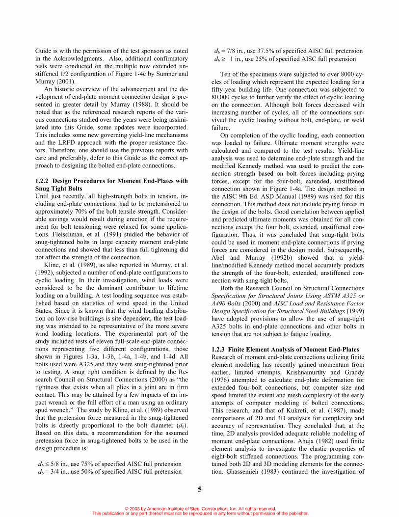
1.2.2 Design Procedures for Moment End-Plates with Snug Tight Bolts Until just recently, all high-strength bolts in tension, in-cluding end-plate connections, had to be pretensioned to approximately 70% of the bolt tensile strength. Consider-able savings would result during erection if the require-ment for bolt tensioning were relaxed for some applica-tions. Fleischman, et al. (1991) studied the behavior of snug-tightened bolts in large capacity moment end-plate connections and showed that less than full tightening did not affect the strength of the connection.
Kline, et al. (1989), as also reported in Murray, et al. (1992), subjected a number of end-plate configurations to cyclic loading. In their investigation, wind loads were considered to be the dominant contributor to lifetime loading on a building. A test loading sequence was estab-lished based on statistics of wind speed in the United States. Since it is known that the wind loading distribu-tion on low-rise buildings is site dependent, the test load-ing was intended to be representative of the more severe wind loading locations. The experimental part of the study included tests of eleven full-scale end-plate connec-tions representing five different configurations, those shown in Figures 1-3a, 1-3b, 1-4a, 1-4b, and 1-4d. All bolts used were A325 and they were snug-tightened prior to testing. A snug tight condition is defined by the Re-search Council on Structural Connections (2000) as “the tightness that exists when all plies in a joint are in firm contact. This may be attained by a few impacts of an im-pact wrench or the full effort of a man using an ordinary spud wrench.” The study by Kline, et al. (1989) observed that the pretension force measured in the snug-tightened bolts is directly proportional to the bolt diameter (db).Based on this data, a recommendation for the assumed pretension force in snug-tightened bolts to be used in the design procedure is:
db 5/8 in., use 75% of specified AISC full pretension db = 3/4 in., use 50% of specified AISC full pretension
db = 7/8 in., use 37.5% of specified AISC full pretension db 1 in., use 25% of specified AISC full pretension
Ten of the specimens were subjected to over 8000 cy-cles of loading which represent the expected loading for a fifty-year building life. One connection was subjected to 80,000 cycles to further verify the effect of cyclic loading on the connection. Although bolt forces decreased with increasing number of cycles, all of the connections sur-vived the cyclic loading without bolt, end-plate, or weld failure.
On completion of the cyclic loading, each connection was loaded to failure. Ultimate moment strengths were calculated and compared to the test results. Yield-line analysis was used to determine end-plate strength and the modified Kennedy method was used to predict the con-nection strength based on bolt forces including prying forces, except for the four-bolt, extended, unstiffened connection shown in Figure 1-4a. The design method in the AISC 9th Ed. ASD Manual (1989) was used for this connection. This method does not include prying forces in the design of the bolts. Good correlation between applied and predicted ultimate moments was obtained for all con-nections except the four bolt, extended, unstiffened con-figuration. Thus, it was concluded that snug-tight bolts could be used in moment end-plate connections if prying forces are considered in the design model. Subsequently, Abel and Murray (1992b) showed that a yield-line/modified Kennedy method model accurately predicts the strength of the four-bolt, extended, unstiffened con-nection with snug-tight bolts.
Both the Research Council on Structural Connections Specification for Structural Joints Using ASTM A325 or A490 Bolts (2000) and AISC Load and Resistance Factor Design Specification for Structural Steel Buildings (1999) have adopted provisions to allow the use of snug-tight A325 bolts in end-plate connections and other bolts in tension that are not subject to fatigue loading.
1.2.3 Finite Element Analysis of Moment End-Plates Research of moment end-plate connections utilizing finite element modeling has recently gained momentum from earlier, limited attempts. Krishnamurthy and Graddy (1976) attempted to calculate end-plate deformation for extended four-bolt connections, but computer size and speed limited the extent and mesh complexity of the early attempts of computer modeling of bolted connections. This research, and that of Kukreti, et al. (1987), made comparisons of 2D and 3D analyses for complexity and accuracy of representation. They concluded that, at the time, 2D analysis provided adequate reliable modeling of moment end-plate connections. Ahuja (1982) used finite element analysis to investigate the elastic properties of eight-bolt stiffened connections. The programming con-tained both 2D and 3D modeling elements for the connec-tion. Ghassemieh (1983) continued the investigation of
© 2003 by American Institute of Steel Construction, Inc. All rights reserved.This publication or any part thereof must not be reproduced in any form without permission of the publisher.

6
Ahuja to include non-linear behavior of the end-plate and bolts. Kukreti, et al. (1990) continued finite element mod-eling for an eight-bolt connection and, as with previous research, conducted parametric studies to predict end-plate displacement and inner bolt forces. These predic-tions were compared to experimental data for correlation. Regression analysis of the data was conducted to provide empirical equations for design of moment end-plates un-der monotonic loads.
Use of the finite element code ABAQUS by Bursi and Leonelli (1994) aided in prediction of end-plate deforma-tion and displacement for extended end-plates. The finite element code ANSYS has successfully been utilized by Bahaari and Sherbourne (1993) to model extended end-plates. Both codes have successfully produced three-dimensional modeling of the end-plates and provided valid predictions and analysis of both thick and thin plate behavior and deformation. Most finite element models of moment end-plate connections have analyzed monotonic loading, although Meng (1996) was successful in model-ing a connection under seismic loading.
Advances in finite element research of moment end-plates are continuing at various universities, such as using 3D non-linear modeling to simulate hysteresis loop be-havior and response due to varied loading. These re-sponses are then used to predict component failure within end-plate connections.
1.2.4 Performance of Moment End-Plate Connections for Seismic LoadingCyclic loading of moment end-plate connections was first studied by Popov and Tsai (1989). Since that time a num-ber of studies have been conducted worldwide. Two stud-ies that used design procedures similar to those in this Guide are Meng and Murray (1997) and Sumner, et al.(2000).
Meng and Murray (1997) conducted a series of tests using the four-bolt extended, unstiffened connection shown in Figure 1-4a. The connections were designed using the yield-line and modified Kennedy procedures that include prying force effects in the bolt design. The test specimens were designed such that the connection was stronger than the connected beam. Each specimen was subjected to the Applied Technology Council (ATC-24) protocol loading (ATC 1992). Even though bolt forces decreased from the fully tightened level (in some tests, even to zero) as the testing progressed, failure oc-curred in the beam for every test. If weld access holes were not used, robust hysteresis loops were obtained. In all the specimens tested with weld access holes, flange fracture at the weld access hole occurred a few cycles into the inelastic regime of the ATC-24 protocol. Subsequent finite element analysis showed that the presence of a weld access hole significantly increases flange strain adjacent to the hole. Meng and Murray recommended that weld access holes not be used in moment end-plate connec-tions.
As part of the SAC Joint Venture, Sumner, et al.(2000) conducted beam-to-column tests using the SAC Protocol (1997). Their test matrix included the four-bolt extended, unstiffened end-plate connection. For each end-plate geometry, two tests were performed: one with the connection design to develop 110 percent of the nominal plastic moment strength of the beam (strong plate connec-tion) and the other with the connection designed to de-velop 80 percent of the plastic moment strength of the beam (weak plate connection). It was found that the four-bolt extended, unstiffened end-plate connection can be designed and detailed to be suitable for seismic loading. A design procedure, very similar to the procedure con-tained in this Guide, was then developed. The procedure is found in the Federal Emergency Management Agency (FEMA) Recommended Seismic Design Criteria for New Steel Moment-Frame Buildings (2000).
© 2003 by American Institute of Steel Construction, Inc. All rights reserved.This publication or any part thereof must not be reproduced in any form without permission of the publisher.

7
Chapter 2 DESIGN PROCEDURES 2.1 Introduction The design procedures for the four flush and five ex-tended moment end-plate connections used in this Guide were developed at the University of Oklahoma and Vir-ginia Polytechnic Institute and are based on a) yield-line theory, b) a method to predict bolt forces including prying effects, and c) moment-rotation considerations. More specifically the design procedures provide:
1. Determination of end-plate thickness by yield-line theory given end-plate geometry, beam ge-ometry, and material yield stress; a strength cri-terion.
2. Determination of bolt forces including prying forces given end-plate geometry, bolt diameter, and bolt type; a bolt force criterion.
3. An assessment of construction type for which the connection is suitable; a stiffness criterion.
The procedures were verified using a series of full-scale tests of each of the nine connections shown in Fig-ures 1-3 and 1-4 (Srouji, et al. 1983a, 1983b; Hendrick, et al. 1984, 1985; Morrison, et al. 1985, 1986; Abel and Murray 1992a, 1992b; and SEI 1984). The geometric parameters for each series were varied within limits de-termined from current practice of the low rise building industry.
The basis for each part of the design procedure is briefly described in the following sections. More thor-ough descriptions are found in the references cited.
2.2 Yield-Line Theory and Mechanics Yield-lines are the continuous formation of plastic hinges along a straight or curved line. It is assumed that yield-lines divide a plate into rigid plane regions since elastic deformations are negligible when compared with plastic deformations. Although the failure mechanism of a plate using yield-line theory was initially developed for rein-forced concrete, the principles and findings are also ap-plicable to steel plates.
The analysis of a yield-line mechanism can be per-formed by two different methods, (1) the equilibrium method, or (2) the virtual work energy method. The latter method is more suitable for the end-plate application. In this method, the external work done by the applied load, in moving through a small arbitrary virtual deflection field, is equated to the internal work done as the plate rotates at the yield lines to facilitate this virtual deflection field. For a selected yield-line pattern and loading, spe-cific plastic moment strength is required along these hinge lines. For the same loading, other patterns may re-
sult in larger required plastic moment strength. Hence, the appropriate pattern is the one, which requires the largest required plastic moment strength along the yield-lines. Conversely, for a given plastic moment strength along the yield-lines, the appropriate mechanism is that which pro-duces the smallest ultimate load. This implies that the yield-line theory is an upper bound procedure; therefore, one must find the least upper bound.
The procedure to determine an end-plate plastic mo-ment strength, or ultimate load, is to first arbitrarily select possible yield-line mechanisms. Next, the external work and internal work are equated, thereby establishing the relationship between the applied load and the ultimate resisting moment. This equation is then solved for either the unknown load or the unknown resisting moment. By comparing the values obtained from the arbitrarily se-lected mechanisms, the appropriate yield-line mechanism is the one with the largest required plastic moment strength or the smallest ultimate load.
The controlling yield-line mechanisms for each of the
nine end-plate connections considered in this Guide are shown in Chapters 3 and 4.
2.3 Bolt Force PredictionsYield-line theory does not provide bolt force predictions that include prying action forces. Since experimental test results indicate that prying action behavior is present in end-plate connections, a variation of the method sug-gested by Kennedy, et al. (1981) was adopted to predict bolt forces as a function of applied flange force.
MMM
M M
M
2F
b b
2 1 1 2
pf pfa a
B BQ Q
Figure 2-1 Split-tee model.
© 2003 by American Institute of Steel Construction, Inc. All rights reserved.This publication or any part thereof must not be reproduced in any form without permission of the publisher.

8
B B
2F
(a) First Stage / Thick Plate Behavior
Q
a
B
a
B Q
2F
(b) Second Stage / Intermediate Plate Behavior
2F
a
Q BB
a
max Q max
(c) Third Stage / Thin Plate Behavior
Figure 2-2 Flange behavior models.
The Kennedy method is based on the split-tee analogy and three stages of plate behavior. Consider a split-tee model, Figure 2-1, consisting of a flange bolted to a rigid support and attached to a web through which a tension load is applied.
At the lower levels of applied load, the flange behav-ior is termed “thick plate behavior”, as plastic hinges have
not formed in the split-tee flange, Figure 2-2a. As the applied load is increased, two plastic hinges form at the centerline of the flange and each web face intersection, Figure 2-2b. This yielding marks the “thick plate limit” and the transition to the second stage of plate behavior termed “intermediate plate behavior.” At a greater applied load level, two additional plastic hinges form at the cen-terline of the flange and each bolt, Figure 2-2c. The for-mation of this second set of plastic hinges marks the “thin plate limit” and the transition to the third stage of plate behavior termed “thin plate behavior.”
For all stages of plate behavior, the Kennedy method predicts a bolt force as the sum of a portion of the applied force and a prying force. The portion of the applied force depends on the applied load, while the magnitude of the prying force depends on the stage of plate behavior. For the first stage of behavior, or thick plate behavior, the prying force is zero. For the second stage of behavior, or intermediate plate behavior, the prying force increases from zero at the thick plate limit to a maximum at the thin plate limit. For the third stage of behavior, or thin plate behavior, the prying force is maximum and constant.
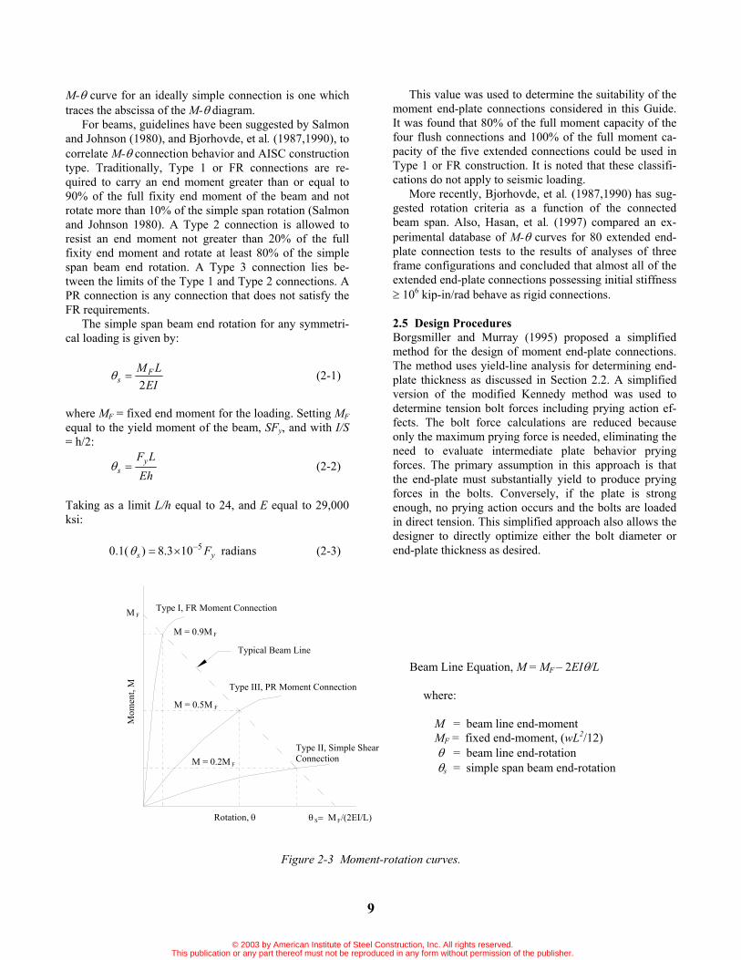
2.4 Moment-Rotation Relationships Connection stiffness is the rotational resistance of a con-nection to applied moment. This connection characteristic is often described with a moment versus rotation or M-diagram. The initial slope of the M- curve, typically ob-tained from experimental test data, is an indication of the rotational stiffness of the connection, i.e. the greater the slope of the curve, the greater the stiffness of the connec-tion.
This stiffness is reflected in the three types of con-struction defined in the AISC Specification for Structural Steel Buildings -- Allowable Stress Design and Plastic Design (1989): Type 1, Type 2, and Type 3. Type 1 con-struction, or rigid framing, assumes that the connections have sufficient rigidity to fully resist rotation at joints. Type 2 construction, or simple framing, assumes that the connections are free to rotate under gravity load and that beams are connected for shear only. Type 3 construction, or semi-rigid framing, assumes that connections have a dependable and known moment capacity as a function of rotation between that of Type 1 and Type 2 construction. The AISC Load and Resistance Factor Design Specifica-tion for Structural Steel Buildings (1999) defines two types of construction: FR and PR. Fully restrained or FR construction is the same as ASD Type 1 construction. Partially restrained or PR construction encompasses ASD Types 2 and 3 construction. Idealized M- curves for three typical connections representing the three AISC types of construction are shown in Figure 2-3. Note that the M- curve for an ideally fixed connection is one which traces the ordinate of the M- diagram, whereas the
© 2003 by American Institute of Steel Construction, Inc. All rights reserved.This publication or any part thereof must not be reproduced in any form without permission of the publisher.
9
M- curve for an ideally simple connection is one which traces the abscissa of the M- diagram.
For beams, guidelines have been suggested by Salmon and Johnson (1980), and Bjorhovde, et al. (1987,1990), to correlate M- connection behavior and AISC construction type. Traditionally, Type 1 or FR connections are re-quired to carry an end moment greater than or equal to 90% of the full fixity end moment of the beam and not rotate more than 10% of the simple span rotation (Salmon and Johnson 1980). A Type 2 connection is allowed to resist an end moment not greater than 20% of the full fixity end moment and rotate at least 80% of the simple span beam end rotation. A Type 3 connection lies be-tween the limits of the Type 1 and Type 2 connections. A PR connection is any connection that does not satisfy the FR requirements.
The simple span beam end rotation for any symmetri-cal loading is given by:
EILM F
s 2 (2-1)
where MF = fixed end moment for the loading. Setting MFequal to the yield moment of the beam, SFy, and with I/S= h/2:
EhLFy
s (2-2)
Taking as a limit L/h equal to 24, and E equal to 29,000 ksi:
0.1( ys F5103.8) radians (2-3)
This value was used to determine the suitability of the moment end-plate connections considered in this Guide. It was found that 80% of the full moment capacity of the four flush connections and 100% of the full moment ca-pacity of the five extended connections could be used in Type 1 or FR construction. It is noted that these classifi-cations do not apply to seismic loading.
More recently, Bjorhovde, et al. (1987,1990) has sug-gested rotation criteria as a function of the connected beam span. Also, Hasan, et al. (1997) compared an ex-perimental database of M- curves for 80 extended end-plate connection tests to the results of analyses of three frame configurations and concluded that almost all of the extended end-plate connections possessing initial stiffness
106 kip-in/rad behave as rigid connections.
2.5 Design ProceduresBorgsmiller and Murray (1995) proposed a simplified method for the design of moment end-plate connections. The method uses yield-line analysis for determining end-plate thickness as discussed in Section 2.2. A simplified version of the modified Kennedy method was used to determine tension bolt forces including prying action ef-fects. The bolt force calculations are reduced because only the maximum prying force is needed, eliminating the need to evaluate intermediate plate behavior prying forces. The primary assumption in this approach is that the end-plate must substantially yield to produce prying forces in the bolts. Conversely, if the plate is strong enough, no prying action occurs and the bolts are loaded in direct tension. This simplified approach also allows the designer to directly optimize either the bolt diameter or end-plate thickness as desired.
Rotation,
Mom
ent,
M
M = 0.9M
Typical Beam Line
Type I, FR Moment Connection
Type III, PR Moment Connection
Type II, Simple Shear Connection
F
M = 0.5M F
M = 0.2M F
M F
M /(2EI/L)S F
Beam Line Equation, M = MF – 2EI /L
where:
M = beam line end-moment MF = fixed end-moment, (wL2/12)
= beam line end-rotation s = simple span beam end-rotation
Figure 2-3 Moment-rotation curves.
© 2003 by American Institute of Steel Construction, Inc. All rights reserved.This publication or any part thereof must not be reproduced in any form without permission of the publisher.

10
Specifically, Borgsmiller and Murray (1995) exam-ined 52 tests and concluded that the threshold when pry-ing action begins to take place in the bolts is at 90% of the full strength of the plate, or 0.90Mpl. If the applied load is less than this value, the end-plate behaves as a thick plate and prying action can be neglected in the bolts. Once the applied moment crosses the threshold of 0.90Mpl, the plate can be approximated as a thin plate and maximum prying action is incorporated in the bolt analy-sis.
The design procedures used in Chapter 3 for flush end-plates and in Chapter 4 for extended end-plates are based on the Borgsmiller and Murray (1995) approach. For a specific design, if it is desired to minimize bolt di-ameter, Design Procedure 1 is used. If it is desired to minimize the thickness of the end-plate, Design Proce-dure 2 is used. A flow chart is provided in Figure 2-4 that provides a summary of the design procedures outlined in Sections 2.5.1 and 2.5.2.
For LRFD designs, Mu is the required flexural strength (factored moment). For ASD designs the working mo-ment or service load moment, Mw, is multiplied by 1.5 to obtain Mu. After determining Mu, the design procedures are exactly the same for ASD and LRFD.
2.5.1 Design Procedure 1:Thick End-Plate and Smaller Diameter Bolts:The following procedure results in a design with a rela-tively thick end-plate and smaller diameter bolts. The design is governed by bolt rupture with no prying action included, requiring “thick” plate behavior. The “summary tables” refer to Tables 3-2 through 3-5 for the flush end-plate connections and Tables 4-2 through 4-6 for the ex-tended end-plate connections. The design steps are:
1.) Determine the required bolt diameter assuming no prying action,
nt
ureqdb dF
Md 2, (2-4)
where,
= 0.75 Ft = bolt material tensile strength, specified in Ta-
ble J3.2, AISC (1999), i.e. Ft = 90 ksi for A325 and Ft = 113 ksi for A490 bolts.
Mu = required flexural strength dn = distance from the centerline of the nth tension
bolt row to the center of the compression flange.
Note: This equation is derived from equating Mu to Mnp as shown in the "summary tables" in Chapter 3
for flush end-plates and Chapter 4 for extended end-plates as follows:
ntnpu dPMM 2 (2-5)
Solving Equation 2-5 for Pt yields:
n
ut d
MP
2 (2-6)
Setting Equation 2-6 equal to the bolt proof load
equation, tb FdP
4
2
t and solving for db yields
Equation 2-4.
2.) Solve for the required end-plate thickness, tp,reqd,
YFM
tpy
npp,reqd
b
r)11.1( (2-7)
where,b = 0.90 r = a factor, greater than or equal to 1.0, used
to modify the required factored moment to limit the connection rotation at ultimate moment to 10% of the simple span rota-tion. (See Section 3.1.1 for further explana-tion)
= 1.25 for flush end-plates and 1.0 for ex-tended end-plates
Fpy = end-plate material yield strength Y = yield-line mechanism parameter defined
for each connection in the "summary ta-bles" in Chapter 3 for flush end-plates and Chapter 4 for extended end-plates.
Mnp = connection strength with bolt rupture limit state and no prying action (Equation 2-5 based on selected bolt size).
Note: This equation is derived from equating Mnp to 90% of the design strength for end-plate yielding,
bMpl, given in the "summary tables" as follows:
YtFMM ppybplbnp290.090.0 (2-8)
Solving for tp, along with the inclusion of the load factor r, yields Equation 2-7. Note that the reciprocal of the 0.90 factor (1.11) is placed in the numerator to avoid confusion with the bending resistance factor bof the same value.
© 2003 by American Institute of Steel Construction, Inc. All rights reserved.This publication or any part thereof must not be reproduced in any form without permission of the publisher.

2.5.2 Design Procedure 2;Thin End-Plate and Larger Diameter Bolts:The following procedure results in a design with a rela-tively thin end-plate and larger diameter bolts. The designis governed by either the yielding of the end-plate or boltrupture when prying action is included, requiring "thin"plate behavior. The "summary tables" refer to Tables 3-2through 3-5 for the flush end-plate connections and Ta-bles 4-2 through 4-6 for the extended end-plate connec-tions. The design steps are:
1.) Determine the required plate thickness,
(2-9)
Note: This equation is derived from equating togiven in the "summary tables" as follows:
(2-10)
2.) Select a trial bolt diameter, and calculate themaximum prying force.
For flush end-plate connections and for the interiorbolts of extended end-plate connections, calculate
as follows:
Note that for flush connections Also, the lastterm in the numerator of Equation 2-14 represents thecontribution of bolt shank bending in Figure 2-1).
For extended connections, also calculate basedon the outer bolts as follows:
If the radical in either expression for (Equations2-11 and 2-15) is negative, combined flexural andshear yielding of the end-plate is the controlling limitstate and the end-plate is not adequate for the speci-fied moment.
3.) Calculate the connection design strength for the limitstate of bolt rupture with prying action as follows:
For a flush connection:
11
(2-15)
(2-16)
(2-17)
(2-18)
For an extended connection:
(2-19)where,
distance from the Centerline of each tensionbolt row to the center of the compressionflange (Note: For rows that do not exist in aconnection, that distance d is taken as zero),specified pretension in Table J3.7 of AISCASD or Table J3.1 of AISC LRFD (also re-produced in Table 2-1 of this Guide).
(2-11)
(2-12)
(2-13)
(2-14)
Rev.3/1/03
Rev.3/1/03
min
Rev.3/1/03
© 2003 by American Institute of Steel Construction, Inc. All rights reserved.This publication or any part thereof must not be reproduced in any form without permission of the publisher.
=3.682
2
3.682

12
Note: For A325 snug-tightened bolts, the following values of Tb should be used:
db 5/8 in., Tb = 75% of minimum bolt pretension db = 3/4 in., Tb = 50% of minimum bolt pretension db =7/8 in., Tb = 37.5% of minimum bolt pretension db 1 in., Tb = 25% of minimum bolt pretension
4.) Check that Mq > Mu. If necessary, adjust the bolt diameter until Mq is greater than Mu.
Table 2-1 Minimum Bolt Pretension, Tb (kips) Bolt Size (in.) A325 A490
1/2 12 15 5/8 19 24 3/4 28 35 7/8 39 49 1 51 64
1 1/8 56 80 1 1/4 71 102 1 3/8 85 121 1 1/2 103 148
2.5.3 Additional Assumptions and Conditions The following assumptions or conditions are inherent in the design procedures:
1. Snug-tight bolts should not be used for other than static loading conditions. Temperature, wind, and snow loads are considered static load-ings. End-plate connections with snug-tight bolts are not recommended for members subjected to large fatigue loading conditions such as heavy crane runways, and supporting structures for machinery and equipment. AISC and RCSC only permit A325 bolts to be snug-tightened (A490 bolts must be fully tightened).
2. The required factored moment for plate design, Mu, should be increased by r = 1.25 for flush end-plate connections if they are assumed to be rigid frame construction as explained in Chapter 3. r = 1.00 for extended connections.
3. Requirements beyond the scope of this Guide must be considered when designing end-plate connections for geographic areas of high seis-micity. Pending further research, snug-tight bolts are not recommended for these applications.
4. The smallest possible pitch distance, pf, (distance from face of beam flange to centerline of nearer bolt) generally results in the most economical connection. The absolute minimum pitch dimen-sion for standard bolts is bolt diameter plus 1/2 in. for bolts up to 1 in. diameter and bolt diame-ter plus 3/4 in. for larger diameter bolts. For ten-
sion control bolts, larger pitch distances are re-quired.
5. End-plate connections can be designed to resist shear force at the interface of the end-plate and column flange using either “bearing” or “slip critical” assumptions. Slip critical connections are only required for other than static loading conditions (see item 1 above). When fully tight-ened or snug-tight bearing type connections are used, it is common practice to assume that the compression bolts resist all of the shear force. When slip critical (type “SC”) are necessary, all bolts at the interface can be assumed to resist the shear force and shear/tension interaction can be ignored as explained in the Commentary on Specification for Structural Joints Using ASTM A325 or A490 Bolts (RCSC 1985). This Com-mentary states: “Connections of the type…in which some of the bolts lose a part of their clamping force due to applied tension suffer no overall loss of frictional resistance. The bolt ten-sion produced by the moment is coupled with a compensating compressive force on the other side of the axis of bending.” Thus, the frictional resistance of the connection remains unchanged. If a bearing type connection is used, it is com-mon practice to assume that the compression bolts resist all of the shear force.
6. The width of the end-plate, which is effective in resisting the applied beam moment, shall not be taken greater than the beam flange width plus 1 inch in the calculations.
7. The gage of the tension bolts (horizontal dis-tance between vertical bolt lines) should not ex-ceed the beam tension flange width.
8. Normally, the beam flange to end-plate weld is designed to develop the yield strength of the connected beam flange. This is usually done with full penetration welds but alternatively, fil-let welds may be used for thin flanges. When the applied moment is less than the design flexural strength of the beam, the beam flange to end-plate weld can be designed for the required mo-ment strength but not less than 60 percent of the specified minimum yield strength of the con-nected beam flange.
9. Beam web to end-plate welds in the vicinity of the tension bolts are to be designed to develop the yield strength of the beam web unless the full design strength of the beam is not required. When the full design strength is not required, the beam web to end-plate welds should be designed to develop 60 percent of the minimum specified yield strength of the beam web.
10. For beam shear resistance in the web at the end-plate, only the distance between the mid-depth of
© 2003 by American Institute of Steel Construction, Inc. All rights reserved.This publication or any part thereof must not be reproduced in any form without permission of the publisher.

13
the beam and the inside face of the beam com-pression flange, or between the inner row of ten-sion bolts plus two bolt diameters and the inside face of the beam compression flange, whichever is smaller, shall be used. This assumption is based on engineering judgment; literature was not found to substantiate or contradict this as-sumption.
11. To the writers’ knowledge, tests of end-plate moment connections with axial forces have not been conducted. Inclusion of axial forces in an end-plate yield-line analysis results in an effec-tive end-plate moment equal to the applied mo-ment plus (tension) or minus (compression) the axial force times one-half the beam depth. See Example 4.2.3 for the design procedure modified to include an axial load.
12. Stitch bolts are sometimes used between the ten-sion and compression flange end-plate bolts, es-pecially in deep connections. The purpose of these bolts is to reduce plate separation caused by welding distortions. Because stitch bolts are located near the center of gravity of the member, the contribution to connection strength is small and is neglected.
13. Web and web stiffener design is not included in the design procedures in this Guide. Most end-plate strength tests have been conducted with relatively thick webs to avoid premature web failure. In a number of tests, beam webs near the tension bolts have been instrumented with strain gages with yielding of the beam web plate re-ported. Pending further testing, engineering judgment is required to determine required web and web stiffener size.
14. Column web stiffening (transverse stiffeners or continuity plates and panel zone doubler plates) design is not included in this Design Guide. AISC Design Guide No. 4 - Extended End-Plate Moment Connections (Murray 1990) contains column stiffening design recommendations. Also, see AISC Design Guide No. 13 – Stiffen-ing of Wide-Flange Columns at Moment Con-nections: Wind and Seismic Applications (Carter 1999) for additional guidance.
2.6 Limit States Check ListLimit states (or failure modes) that should be considered in the design of moment end-plate beam-to-column connections are:
1. Flexural yielding of the end-plate material near the tension flange bolts. This state in itself is not limiting, but yielding results in rapid increases in tension bolt forces and excessive rotation.
2. Shear yielding of the end-plate material. This limit state is not usually observed, but shear in combination with bending can result in reduced flexural capacity and stiffness.
3. Shear rupture of end-plate through outside bolt holes.
4. Bolt rupture because of direct load and prying force effects. This limit state is obviously a brit-tle failure mode and is the most critical limit state in an end-plate connection.
5. Bolt rupture or bolt slip in a slip-critical connec-tion due to shear at the interface between the end-plate and column flange.
6. Bearing failure of end-plate or column flange at bolts.
7. Rupture of beam tension flange to end-plate welds or beam web tension region to end-plate welds.
8. Shear yielding of beam web to end-plate weld or of beam web base metal.
9. Column web yielding opposite either the tension or compression flanges of the connected beam.
10. Column web crippling opposite the compression flange of the connected beam.
11. Column web buckling opposite the compression flange of the connected beam.
12. Column flange yielding in the vicinity of the ten-sion bolts. As with flexural yielding of the end-plate, this state in itself is not limiting but results in rapid increases in tension bolt forces and ex-cessive rotation.
13. Column transverse stiffener failure due to yield-ing, local buckling, or weld failure.
14. Column panel zone failure due to shear yielding or web plate buckling.
15. Excessive rotation (flexibility) at the connection due to end-plate and/or column flange bending.
© 2003 by American Institute of Steel Construction, Inc. All rights reserved.This publication or any part thereof must not be reproduced in any form without permission of the publisher.

14
Given: Beam & end plate geometry, connection moment. Find: Connection plate thickness and bolt diameter.
(See Appendix A for Nomenclature)
wu M.M 51 for ASD,
factoredu MM for LRFD
For flush connection: 25.1r
Calculate Y from Tables 3-2 thru 3-5 For extended connection: 00.1r
Calculate minimum Y from Tables 4-2 thru 4-6
Assume a trial bolt diameter,
db
Start
Thick Plate Procedure
?
Procedure 1 Thick plate & smaller diameter bolts
nt
ub,reqd dF
Md 2 , 75.0
dn is bolt distance for nth bolt row
Select a standard bolt dia., reqdbb dd ,
4/2tbt FdP
ntnp dPM 2
YFM
tpyb
nprreqdp
11.1, , 90.0b
Select standard plate, reqdpp tt ,
Procedure 2Thin plate & larger diameter bolts
YFM
tpyb
urreqdp, , 90.0b
Select a standard plate, reqdpp tt ,
End of procedure
Yes No
Go To A
Figure 2-4 Flow-Chart: Bolted end-plate connection design.
© 2003 by American Institute of Steel Construction, Inc. All rights reserved.This publication or any part thereof must not be reproduced in any form without permission of the publisher.

15
ofext
bpo pp
dta
,
3
min
085.0682.3
oftbppypo pFdwbFtF ,32 4880.0285.0
or, )/( ,, ofifio ppFF
22
2
34 p
opy
o
pmax,o tw
FFatw
Q
085.0682.3 3bpi dta , 16/12 bp dbw
iftbppypi pFdwbFtF ,32 4880.0285.0
22
2
34 p
ipy
i
pmax,i tw
FFatw
Q 4/2tbt FdP
Tb = specified pretension in Table J3.7 of AISC ASD or Table J3.1 ofAISC LRFD (also reproduced in Table 2-1 of this Guide). Note: For snug-tightened A325 bolts, the following values of Tbshould be used: db 5/8 in., Tb = 75% of minimum bolt pretension db = 3/4 in., Tb = 50% of minimum bolt pretension db =7/8 in., Tb = 37.5% of minimum bolt pretension db 1 in., Tb = 25% of minimum bolt pretension
3210b
20b31max,it
321b0max,ot
2b31max,it0max,ot
q
ddddTddTddQPdddTdQP
dTddQPdQP
M
222
22222
max
where 75.0
Assume larger trial db
ExtendedEnd Plate?
uq MM?
End.
21b
21max,itq ddT
ddQPM
22
max
where 75.0
A
Yes No
Yes No
Figure 2-4 (Continued) Flow-Chart: Bolted end-plate connection design
© 2003 by American Institute of Steel Construction, Inc. All rights reserved.This publication or any part thereof must not be reproduced in any form without permission of the publisher.

© 2003 by American Institute of Steel Construction, Inc. All rights reserved.This publication or any part thereof must not be reproduced in any form without permission of the publisher.

17
Chapter 3 FLUSH END-PLATE DESIGN
3.1 Design Equations, Limitations, and Definitions3.1.1 Design Equations The design procedures described in Section 2.5 are used in this Chapter for the design of the four-bolt flush end-plate configurations shown in Figure 1-3. Equations re-quired for determination of bolt forces are found in Table 3-1. Controlling yield-line patterns and the remaining design equations are found in Tables 3-2 through 3-5 for the four configurations.
The expression for Qmax in Table 3-1 contains terms in a radical. If the quantity inside the radical is negative, combined flexural and shear yielding of the end-plate is the controlling limit state and the end-plate is not ade-quate for the specified moment. A thicker end-plate is thus required.
For either ASD Type 1 or LRFD FR rigid frame con-struction, the required factored moment, Mu, must be in-creased 25% to limit the connection rotation at ultimate moment to 10% of the simple span beam rotation. There-fore, the factor r = 1.25 is used in the procedure for the flush connection plate design.
Connections can be designed using either pretensioned or snug-tight bolts. For fully tightened bolts, the preten-sion force, Tb in Table 3-1, is the specified force in Table J3.7 of the AISC ASD Specification or Table J3.1 of the AISC LRFD Specification (also, see Table 2-1 of this Guide for these specified minimum pretension forces). For snug-tightened A325 bolts, the pretension force, Tb, is taken as a percentage of the AISC specified pretension force of Table J3.7 (AISC ASD) or Table J3.1 (AISC LRFD) as indicated in Table 3-1.
3.1.2 Limitations The analytical procedures were verified through tests, Srouji et al. (1983a, 1983b), and Hendrick et al. (1984, 1985), in which geometric parameters were varied among the test configurations. Significant changes in the geomet-ric relationships could affect the mechanism configuration and thus the predicted strength. Therefore, the tested pa-rameter ranges given in Table 3-6 apply to the design equations for the flush end-plate configurations.
3.1.3 Definitions The definitions of the principal variables in Tables 3-1 through 3-5 follow. Definitions for other variables are in Appendix A.
Pt = bolt tensile strength = bolt proof load = AbFtTb = bolt pretension force
Qmax = maximum possible bolt prying force Mn = nominal strength of connection
Mpl = nominal connection strength for the limit state of end-plate yielding
Mq = nominal connection strength for the limit state of bolt fracture with prying action
Mnp = nominal connection strength for the limit state of bolt fracture with no prying action
w = effective width of end-plate per bolt minus the bolt hole diameter
Table 3-1 Summary of Bolt Force Prediction Equations for Flush End-Plate Connections
Bolt Proof Load
tb
tbt Fd
FAP4
2
Ft = nominal tensile strength of bolts = 90 ksi for A325 = 113 ksi for A490
(Table J3.2, AISC LRFD Specification)
Bolt Preten-
sion
Fully-tightened boltsTb = specified pretension force in Table J3.1,
AISC LRFD Specification for fully tight-ened bolts (ASD Table J3.7).
Snug-tightened A325 boltsTb is taken as the following percentage of the AISC specified full pretension given in Table J3.1, AISC LRFD Specification (ASD Table J3.7)
db 5/8 in., use 75% db = 3/4 in., use 50% db = 7/8 in., use 37.5% db 1 in., use 25%
Maxi-mum
Prying Force1
22
2
34 p
ipy
i
pmax,i tw
FFatw
Q
where,
085.0682.33
b
pi d
ta
)16/1(2/ bp dbw
if
tbppyp
i p
Fdwb
FtF
,
32
48
80.02
85.0
1 If the radical in the expression for Qmax is negative, com-bined flexural and shear yielding of the end-plate is the con-trolling limit state and the end-plate is not adequate for the specified moment.
© 2003 by American Institute of Steel Construction, Inc. All rights reserved.This publication or any part thereof must not be reproduced in any form without permission of the publisher.

Tabl
e 3-
2 S
umm
ary
of T
wo-
Bolt
Flus
h U
nstif
fene
d M
omen
t End
-Pla
te A
naly
sis
Geo
met
ry
Yiel
d-Li
ne M
echa
nism
Bo
lt Fo
rce
Mod
el
End-
Plat
e
Yiel
d
YtF
MM
ppy
bpl
bn
2
)(
22
sp
hg
s1p1
hb
Yf
1f
1p
N
ote:
Use
pf =
s, i
f pf >
s
gb
sp
21b =
0.9
0
Bolt
Rup
ture
w/P
ryin
g Ac
tion
1b
1m
axt
qn
dT
dQ
PM
M)
(2)
(2
max
= 0
.75
Bolt
Rup
ture
No
Pryi
ng A
ctio
n 1
tnp
nd
PM
M)
(2 =
0.7
5
t w
ptg
h
p f
bp
t f
s
h 1M
q1d
2(P
- Q
)
tm
ax
© 2003 by American Institute of Steel Construction, Inc. All rights reserved.This publication or any part thereof must not be reproduced in any form without permission of the publisher.
18

Tabl
e 3-
3 S
umm
ary
of F
our-
Bolt
Flus
h U
nstif
fene
d M
omen
t End
-Pla
te A
naly
sis
Geo
met
ry
Yiel
d-Li
ne M
echa
nism
Bo
lt Fo
rce
Mod
el
End-
Plat
e
Yiel
d
Yt
FM
Mp
pyb
plb
n2
225.0
75.02
11
2g
ps
hp
ph
gs
hp
hb
Yb
2b
f1
2f
1p
Not
e: U
se p
f = s
, if p
f > s
gb
sp
21b =
0.9
0
Bolt
Rup
ture
w/P
ryin
g Ac
tion
))(
(2)
)((2
max
21
b
21
max
tq
nd
dT
dd
QP
MM
= 0
.75
Bolt
Rup
ture
No
Pryi
ng A
ctio
n )
)((2
21
tnp
nd
dP
MM
= 0
.75
t
pt
wh
b
gp
p f p b
ft
s
hh 1
2
Mq
d 2d
1
2(P
- Q
)
2(P
- Q
)
tm
ax
tm
ax
© 2003 by American Institute of Steel Construction, Inc. All rights reserved.This publication or any part thereof must not be reproduced in any form without permission of the publisher.
19

Tabl
e 3-
4 S
umm
ary
of F
our-
Bolt
Flus
h St
iffen
ed M
omen
t End
-Pla
te A
naly
sis (
Stiff
ened
Bet
wee
n th
e Te
nsio
n Bo
lt Ro
ws)
Geo
met
ry
Yiel
d-Li
ne M
echa
nism
Bo
lt Fo
rce
Mod
el
End-
Plat
e
Yiel
d
Yt
FM
Mp
pyb
plb
n2
)(
)(
21
11
12
,,
,,
is
2o
sf
1i
s2
os
f1
pp
sh
pp
hg
ps
hp
ph
bY
Not
e: U
se p
f = s
, if p
f > s
gb
sp
21b =
0.9
0
Bolt
Rup
ture
w/P
ryin
g Ac
tion
))(
(2)
)((2
max
21
b
21
max
tq
nd
dT
dd
QP
MM
= 0
.75
Bolt
Rup
ture
No
Pryi
ng A
ctio
n )
)((2
21
tnp
nd
dP
MM
= 0
.75
p
w
pt
t
ft
h
b
pb
g
p fp s,o s,ip
t ss
hh 1
2
2(P
- Q
)
2(P
- Q
)
qM
d 21d
tm
ax
tm
ax
© 2003 by American Institute of Steel Construction, Inc. All rights reserved.This publication or any part thereof must not be reproduced in any form without permission of the publisher.
20

Tabl
e 3-
5 S
umm
ary
of F
our-
Bolt
Flus
h St
iffen
ed M
omen
t End
-Pla
te A
naly
sis (
Stiff
ened
Insi
de th
e Te
nsio
n Bo
lt Ro
ws)
Geo
met
ry
Yiel
d-Li
ne M
echa
nism
Bo
lt Fo
rce
Mod
el
End-
Plat
e
Yiel
d
YtF
MM
ppy
bpl
bn
2
225.0
75.02
11
2g
ps
hp
ph
gs
hp
hb
Yb
2b
f1
2f
1p
Not
e: U
se p
f = s
, if p
f > s
sp
pg
bs
21
(N
ote
uppe
r bou
nd o
n s
for t
his
conn
ectio
n)b =
0.9
0
Bolt
Rup
ture
w/P
ryin
g Ac
tion
))(
(2)
)((2
max
21
b
21
max
tq
nd
dT
dd
QP
MM
= 0
.75
Bolt
Rup
ture
No
Pryi
ng A
ctio
n )
)((2
21
tnp
nd
dP
MM
= 0
.75
t p
t f
t w
g
b
h
p f p
bp
p s
t s
h1h
2
s
d 12d
2(P
- Q
)
2(P
- Q
)
Mq
tm
ax
tm
ax
© 2003 by American Institute of Steel Construction, Inc. All rights reserved.This publication or any part thereof must not be reproduced in any form without permission of the publisher.
21

22
Table 3-6 Tested Parameter Range for Flush End-Plate Connections
Parameter Low (in.) High (in.)
pf 1165 1
87
pb 187
3
g 241 3
43
h 16(a) 24
bp 5 6
tf 163
83
aFor the two-bolt flush connection, the lower limit for depth is 8 in.
3.2 Design ExamplesThe following design examples are in the LRFD format. The same procedures apply for ASD design if the ASD moments are first converted to ultimate by multiplying times 1.5, or factored moments as explained in Section 2.5.
3.2.1 Two-Bolt Flush Unstiffened Moment End-Plate Connection (Table 3-2) The required end-plate thickness and bolt diameter for an end-plate connection with the geometry shown below is to be determined for a required factored moment of 600 k-in.
t f
g
h
pb
fp
1hd 1
s
tw
tp
The end-plate material is A572 Gr 50, the bolts are snug-tightened A325, and the connection is to be used in rigid frame construction as assumed in the frame analysis. Both design procedures are illustrated.
Geometric Design Databp = bf = 6 in. tf = 1/4 in. g = 2 3/4 in. pf = 1 3/8 in. h = 18 in.
Calculate:d1 = 18 – 0.25 – 1.375 – (0.25/2) = 16.25 in. h1 = 16.375 in.
r = 1.25 for flush connections
Design Procedure 1 (Thick End-Plate and Smaller Diameter Bolts):
1.) Solve for the required bolt diameter assuming no pry-ing action,
.in59.025.169075.0
60022,
nt
ureqdb dF
Md
Use db = 5/8 in.
2.) Solve for the required end-plate thickness, tp,reqd,
.in03.275.20.621
21 gbs p
pf = 1.375 in. s use pf = 1.375 in.
)(2112
sphgsp
hb
Y f1f
1p
in.5.10003.2375.1375.1675.22
03.21
375.11375.16
20.6
k6.274/90625.04/ 22FdP tbt
.ink673
)]25.16)(6.27(2[75.02 ntnp dPM
.in45.0
5.1005090.067325.111.111.1 r
, YFM
tpyb
npreqdp
© 2003 by American Institute of Steel Construction, Inc. All rights reserved.This publication or any part thereof must not be reproduced in any form without permission of the publisher.
23
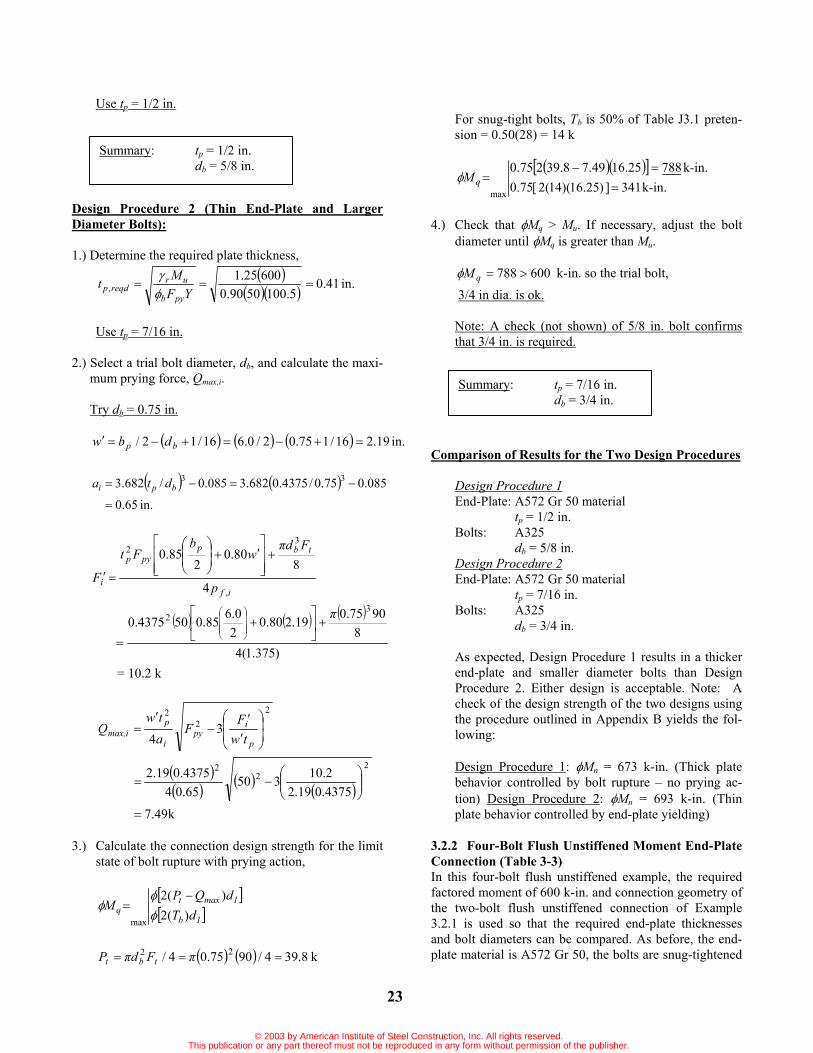
Use tp = 1/2 in.
Design Procedure 2 (Thin End-Plate and Larger Diameter Bolts):
1.) Determine the required plate thickness,
.in41.05.1005090.0
60025.1, YF
Mtpyb
urreqdp
Use tp = 7/16 in.
2.) Select a trial bolt diameter, db, and calculate the maxi-mum prying force, Qmax,i.
Try db = 0.75 in.
in.19.216/175.02/0.616/12/ bp dbw
in.65.0
085.075.0/4375.0682.3085.0/682.3 33bpi dta
if
tbppyp
i p
Fdw
bFt
F,
32
4
880.0
285.0
)375.1(48
9075.019.280.020.685.0504375.0
32
= 10.2 k
22
2
34 p
ipy
i
pmax,i tw
FF
atw
Q
k49.7
4375.019.22.10350
65.044375.019.2
22
2
3.) Calculate the connection design strength for the limit state of bolt rupture with prying action,
1b
1maxtq dT
dQPM
)(2)(2
max
k8.394/9075.04/ 22 FdP tbt
For snug-tight bolts, Tb is 50% of Table J3.1 preten-sion = 0.50(28) = 14 k
.ink341])25.16)(14(2[75.0.ink78825.1649.78.39275.0
max --
M q
4.) Check that Mq > Mu. If necessary, adjust the bolt diameter until Mq is greater than Mu.
600788qM k-in. so the trial bolt, 3/4 in dia. is ok.
Note: A check (not shown) of 5/8 in. bolt confirms that 3/4 in. is required.
Comparison of Results for the Two Design Procedures
Design Procedure 1End-Plate: A572 Gr 50 material
tp = 1/2 in. Bolts: A325
db = 5/8 in. Design Procedure 2End-Plate: A572 Gr 50 material
tp = 7/16 in. Bolts: A325
db = 3/4 in.
As expected, Design Procedure 1 results in a thicker end-plate and smaller diameter bolts than Design Procedure 2. Either design is acceptable. Note: A check of the design strength of the two designs using the procedure outlined in Appendix B yields the fol-lowing:
Design Procedure 1: Mn = 673 k-in. (Thick plate behavior controlled by bolt rupture – no prying ac-tion) Design Procedure 2: Mn = 693 k-in. (Thin plate behavior controlled by end-plate yielding)
3.2.2 Four-Bolt Flush Unstiffened Moment End-Plate Connection (Table 3-3) In this four-bolt flush unstiffened example, the required factored moment of 600 k-in. and connection geometry of the two-bolt flush unstiffened connection of Example 3.2.1 is used so that the required end-plate thicknesses and bolt diameters can be compared. As before, the end-plate material is A572 Gr 50, the bolts are snug-tightened
Summary: tp = 7/16 in. db = 3/4 in.
Summary: tp = 1/2 in. db = 5/8 in.
© 2003 by American Institute of Steel Construction, Inc. All rights reserved.This publication or any part thereof must not be reproduced in any form without permission of the publisher.

24
A325, and the connection is used in rigid frame construc-tion as assumed in the frame analysis. Both LRFD design procedures are illustrated.
Geometric Design Databp = bf = 6 in. tf = 1/4 in. g = 2 3/4 in. pf = 1 3/8 in. pb = 3 in. h = 18 in
Calculate:d1 = 18-1.625-(0.25/2) = 16.25 in., h1 = 16.375 d2 = 18-1.625-(0.25/2)-3 = 13.25 in., h2 = 13.375
r = 1.25 for flush connections
Design Procedure 1 (Thick End-Plate and Smaller Diameter Bolts):
1.) Solve for the required bolt diameter assuming no pry-ing action,
.in44.025.1325.169075.0
6002
2,
nt
ureqdb dF
Md
Use db = 1/2 in.
2.) Solve for the required end-plate thickness, tp,reqd,
gbs p21 03.275.20.6
21 in.
pf = 1.375 in. s use pf = 1.375 in.
22
2
gp25.0shp75.0phg
sh
phb
Y
b2bf1
2
f
1p
0.375.0375.1375.1675.22
03.2375.13
375.1375.16
26.0
in.1.127275.20.325.003.2375.13
k7.174/9050.04/ 22 FdP tbt
.ink783
)]25.1325.16)(7.17(2[75.02 ntnp dPM
.in436.01.1275090.0
78325.111.111.1 r
YFM
tpyb
npp,reqd
Use tp = 7/16 in.
Design Procedure 2 (Thin End-Plate and Larger Di-ameter Bolts):
1.) Determine the required plate thickness,
.in36.01.1275090.0
60025.1YF
Mtpyb
urp,reqd
Use tp = 3/8 in.
2.) Select a trial bolt diameter, db, and calculate the maxi-mum prying force, Qmax,i.
Try db = 1/2 in.
Summary: tp = 7/16 in. db = 1/2 in.
h
gtp
wt
pb
f
pb
p
1h2h
s
2d1d
ft
© 2003 by American Institute of Steel Construction, Inc. All rights reserved.This publication or any part thereof must not be reproduced in any form without permission of the publisher.

25
in.44.216/150.02/0.6
16/12/ bp dbw
in.47.1085.050.0/375.0682.3
085.0/682.33
3bpi dta
if
tbppyp
i p
Fdw
bFt
F,
32
4
880.0
285.0
k56.6)375.1(4
89050.044.280.0
20.685.050375.0
32
22
2
34 p
ipy
i
pmax,i tw
FFatw
Q
k83.2
375.044.256.6350
47.14375.044.2
22
2
3.) Calculate the connection design strength for the limit state of bolt rupture with prying action,
))((2))((2
max 21b
21maxtq ddT
ddQPM
k7.174/9050.04/ 22 FdP tbt
For snug-tight bolts, Tb is 75% of Table J3.1 preten-sion = 0.75(12) = 9 k
.ink398])25.1325.16)(9(2[75.0.ink65825.1325.1683.27.17275.0
max --
M q
4.) Check that Mq > Mu. If necessary, adjust the bolt diameter until Mq is greater than Mu.
600658qM k-in. so the trial bolt, 1/2 in. dia. is ok.
Comparison of Results for the Two Design Procedures
Design Procedure 1End-Plate: A572 Gr 50 material
tp = 7/16 in. Bolts: A325
db = 1/2 in. Design Procedure 2End-Plate: A572 Gr 50 material
tp = 3/8 in. Bolts: A325
db = 1/2 in.
In this example, Design Procedure 2 produces a more economic design since both methods require the same nominal bolt diameter. Different limit states govern the design strengths using the procedure out-lined in Appendix B as follows:
Design Procedure 1: Mn = 783 k-in. (Thick plate behavior controlled by bolt rupture – no prying ac-tion) Design Procedure 2: Mn = 643 k-in. (Thin plate be-havior controlled by end-plate yielding)
3.2.3 Four-Bolt Flush Stiffened Moment End-Plate Connection (Stiffener Between Bolt Rows, Table 3-4) The required end-plate thickness and bolt diameter for an end-plate connection with the geometry shown in the fig-ure below and a required factored moment of 900 k-in. is
to be determined. The end-plate material is A572 Gr 50, the bolts are fully pretensioned A325, and the connection is used in rigid frame construction as assumed in the frame analysis. Both LRFD design procedures are illus-trated.
Summary: tp = 3/8 in. db = 1/2 in.
b
1dd2
tp g
tw
f
s
p
b p
p
ft
h
2h1h
ts
ps,i
s,op
© 2003 by American Institute of Steel Construction, Inc. All rights reserved.This publication or any part thereof must not be reproduced in any form without permission of the publisher.

26
Geometric Design Databp = bf = 6 in. tf = 1/4 in. g = 3 in. pf = 1 1/2 in. pb = 3 in. ps,o = 1 3/8 in. ts = 3/8 in. h = 16 in.
Calculate:d1 = 16-1.5-(0.25/2) = 14.125 in. d2 = 16-1.5-(0.25/2)-3 = 11.125 in. h1 = 14.25 in. h2 = 11.25 in. ps,i = pb-ps,o-ts = 3-1.375-0.375 = 1.25 in.
r = 1.25 for flush connections
Design Procedure 1 (Thick End-Plate and Smaller Diameter Bolts):
1.) Solve for the required bolt diameter assuming no pry-ing action,
.in58.0125.11125.149075.0
9002
2,
nt
ureqdb dF
Md
Use db = 5/8 in.
2.) Solve for the required end-plate thickness, tp,reqd,
gbs p21 12.20.30.6
21 in.
pf = 1.5 in. s Use pf = 1.5 in.
is2osf1
is2
osf1
p
pshpphg
psh
pph
bY
,,
,,
2
11112
25.11
12.2125.11
375.11
5.1125.14
20.6
25.112.225.11375.15.125.140.3
2
= 155.1 in.
k6.274/90625.04/ 22 FdP tbt
.ink1045
)]125.11125.14)(6.27(2[75.02 ntnp dPM
.in46.01.1555090.0
104525.111.111.1 r
YFM
tpyb
npp,reqd
Use tp = 1/2 in.
Design Procedure 2 (Thin End-Plate and Larger Diameter Bolts):
1.) Determine the required plate thickness,
.in40.01.1555090.0
90025.1YF
Mtpyb
urp,reqd
Use tp = 7/16 in.
2.) Select a trial bolt diameter, db, and calculate the maxi-mum prying force, Qmax,i.
Try db = 3/4 in.
in.19.216/175.02/0.6
16/12/ bp dbw
in.65.0085.075.0/4375.0682.3
085.0/682.33
3bpi dta
if
tbppyp
i p
Fdw
bFt
F,
32
4
880.0
285.0
k35.9)5.1(4
89075.019.280.0
20.685.0504375.0
32
22
2
34 p
ipy
i
pmax,i tw
FFatw
Q
k59.7
4375.019.235.9350
65.044375.019.2
22
2
Summary: tp = 1/2 in. db = 5/8 in.
© 2003 by American Institute of Steel Construction, Inc. All rights reserved.This publication or any part thereof must not be reproduced in any form without permission of the publisher.

27
3.) Calculate the connection design strength for the limit state of bolt rupture with prying action,
))((2))((2
max 21b
21maxtq ddT
ddQPM
k8.394/9075.04/ 22 FdP tbt
k9.278.397.07.0 tb PT , or from Table J3.1, Use Tb = 28 k
.ink1061])125.11125.14)(28(2[75.0ink1220125.11125.1459.78.39275.0
max --
M q
4.) Check that Mq > Mu. If necessary, adjust the bolt diameter until Mq is greater than Mu.
9001220qM k-in. so the trial bolt, 3/4 in dia. is ok.
Note: A check (not shown) of 5/8 in. bolt confirms that 3/4 in. is required.
Comparison of Results for the Two Design Procedures
Design Procedure 1End-Plate: A572 Gr 50 material
tp = 1/2 in. Bolts: A325
db = 5/8 in. Design Procedure 2End-Plate: A572 Gr 50 material
tp = 7/16 in. Bolts: A325
db = 3/4 in.
As expected, Design Procedure 1 results in a thicker end-plate and smaller diameter bolts than Design Procedure 2. Either design is acceptable. Note: A check of the design strength of the two designs using the procedure outlined in Appendix B yields the fol-lowing:
Design Procedure 1: Mn = 1045 k-in. (Thick plate behavior controlled by bolt rupture – no prying ac-tion) Design Procedure 2: Mn = 1069 k-in. (Thin plate behavior controlled by end-plate yielding)
3.2.4 Four-Bolt Flush Stiffened Moment End-Plate Connection (Stiffener Inside Bolt Rows, Table 3-5) The required end-plate thickness and bolt diameter for the end-plate geometry shown is to be determined. The same required factored moment, of 900 k-in., and connection geometry of Example 3.2.3 are to be used. The only dif-ference between these examples is the location of the stiffener. As before, the end-plate material is A572 Gr 50, the bolts are fully pretensioned A325, and the connection is used in rigid frame construction. Both LRFD design procedures are illustrated.
Geometric Design Databp = bf = 6 in. tf = 1/4 in. g = 3 in. pf = 1 1/2 in. pb = 3 in. h = 16 in. ps = 1 1/2 in.
Calculate:d1 = 16-1.5-(0.25/2) = 14.125 in. d2 = 16-1.5-(0.25/2)-3 = 11.125 in. h1 = 14.25 in h2 = 11.25 in
r = 1.25 for flush connections
Design Procedure 1 (Thick End-Plate and Smaller Diameter Bolts):
1.) Solve for the required bolt diameter assuming no pry-ing action,
b
1dd2
tp g
tw
f
p
b p
p
ft
h
2h1h
st
ps
s
Summary: tp = 7/16 in. db = 3/4 in.
© 2003 by American Institute of Steel Construction, Inc. All rights reserved.This publication or any part thereof must not be reproduced in any form without permission of the publisher.

28
.in58.0125.11125.149075.0
9002
2,
nt
ureqdb dF
Md
Use db = 5/8 in.
2.) Solve for the required end-plate thickness, tp,reqd,
gbs p21 12.20.30.6
21 in. > ps = 1.5 in.
Use s = 1.5 in.
pf = 1.5 in. s Use pf = 1.5 in.
225.075.02
112
gpshpphg
sh
ph
bY
b2bf1
2f
1p
5.125.11
5.125.14
20.6Y
))0.3(25.05.1(25.11))0.3(75.05.1(25.140.3
2
in.0.10520.3
k6.274/90625.04/ 22 FdP tbt
.ink1045
)]125.11125.14)(6.27(2[75.02 ntnp dPM
.in55.01055090.0
104525.111.111.1 r
YFM
tpyb
npp,reqd
Use tp = 9/16 in.
Design Procedure 2 (Thin End-Plate and Larger Diameter Bolts):
1.) Determine the required plate thickness,
.in49.01055090.0
90025.1YF
Mtpyb
urp,reqd
Use tp = 1/2 in.
2.) Select a trial bolt diameter, db, and calculate the maxi-mum prying force, Qmax,i.
Try db = 5/8 in.
in.31.216/1625.02/0.6
16/12/ bp dbw
in.80.1085.0625.0/50.0682.3
085.0/682.33
3bpi dta
if
tbppyp
i p
Fdw
bFt
F,
32
4
880.0
285.0
k6.10)5.1(4
890625.031.280.0
20.685.05050.0
32
22
2
34 p
ipy
i
pmax,i tw
FFatw
Q
k80.350.031.2
6.1035080.1450.031.2
22
2
3.) Calculate the connection design strength for the limit state of bolt rupture with prying action,
))((2))((2
max 21b
21maxtq ddT
ddQPM
k6.274/90625.04/ 22 FdP tbt
k3.196.277.07.0 tb PT , or from Table J3.1, Use Tb = 19 k
Summary: tp = 9/16 in. db = 5/8 in.
© 2003 by American Institute of Steel Construction, Inc. All rights reserved.This publication or any part thereof must not be reproduced in any form without permission of the publisher.

29
.ink720])125.11125.14)(19(2[75.0ink901125.11125.1480.36.27275.0
max --
M q
4.) Check that Mq > Mu. If necessary, adjust the bolt di-
ameter until Mq is greater than Mu.
900901qM kip-in. so the trial bolt, 5/8 in. dia. is ok.
Comparison of Results for the Two Design Procedures
Design Procedure 1End-Plate: A572 Gr 50 material
tp = 9/16 in. Bolts: A325
db = 5/8 in. Design Procedure 2End-Plate: A572 Gr 50 material
tp = 1/2 in. Bolts: A325
db = 5/8 in.
In this example, Design Procedure 2 produces a more economic design since both methods require the same nominal bolt diameter. Different limit states govern the design strengths using the procedure out-lined in Appendix B as follows:
Design Procedure 1: Mn = 1045 k-in. (Thick plate behavior controlled by bolt rupture – no prying ac-tion) Design Procedure 2: Mn = 901 k-in. (Thin plate be-havior controlled by bolt rupture with prying)
Summary: tp = 1/2 in. db = 5/8 in.
© 2003 by American Institute of Steel Construction, Inc. All rights reserved.This publication or any part thereof must not be reproduced in any form without permission of the publisher.

© 2003 by American Institute of Steel Construction, Inc. All rights reserved.This publication or any part thereof must not be reproduced in any form without permission of the publisher.

31
Chapter 4 EXTENDED END-PLATE DESIGN
4.1 Design Equations, Limitations, and Definitions4.1.1 Design Equations The design procedures described in Section 2.5 are used in this Chapter for the design of the five extended end-plate configurations shown in Figure 1-4. Equations re-quired for determination of bolt forces are found in Table 4-1. Controlling yield-line patterns and the remaining design equations are found in Tables 4-2 through 4-6 for the five configurations.
The expressions for Qmax,i and Qmax,o in Table 4-1 con-tain terms in a radical. If the quantity inside the radical is negative, combined flexural and shear yielding of the end-plate is the controlling limit state and the end-plate is not adequate for the specified moment, therefore, a thicker end-plate is required.
Connections using either pretensioned or snug-tight bolts can be designed. For fully tightened bolts, the pre-tension force, Tb in Table 4-1, is the specified force in Table J3.7 of the AISC ASD Specification or Table J3.1 of the AISC LRFD Specification (also, see Table 2.1 of this Guide for these specified minimum pretension forces). For snug-tightened A325 bolts, the pretension force, Tb, is taken as a percentage of the AISC specified pretension force of Table J3.7 (AISC ASD) or Table J3.1 (AISC LRFD) as indicated in Table 4-1.
4.1.2 Limitations The analytical procedures were verified through tests, Morrison, et al. (1985, 1986), Abel and Murray (1992a, 1992b), and SEI (1984), in which geometric parameters were varied among the test configurations. Significant changes in the geometric relationships could effect the mechanism configuration and thus the predicted strength. Therefore, the tested parameter ranges given in Table 4-7 apply to the design equations for the extended end-plate configurations.
4.1.3 Definitions The definitions of the principal variables in Tables 4-1 through 4-6 follow. Definitions for other variables are in Appendix A.
Pt = bolt tensile strength = bolt proof load = AbFtTb = bolt pretension force
Qmax,i = maximum possible bolt prying force in the ten-sion bolts between the beam flanges
Qmax,o = maximum possible bolt prying force in the ten-sion bolts outside the beam flanges
Mn = nominal strength of connection Mpl = nominal connection strength for the limit state
of end-plate yielding Mq = nominal connection strength for the limit state
of bolt fracture with prying action
Mnp = nominal connection strength for the limit state of bolt fracture with no prying action
w = effective width of end-plate per bolt minus the bolt hole diameter
Table 4-1 Summary of Bolt Force Prediction Equations for Extended End-Plate Connections
Bolt Proof Load
tb
tbt Fd
FAP4
2
Ft = nominal tensile strength of bolts = 90 ksi for A325 = 113 ksi for A490
(Table J3.2, AISC LRFD Specification)
Bolt Preten-
sion
Fully-tightened boltsTb = specified pretension force in Table J3.1,
AISC LRFD Specification for fully tight-ened bolts (ASD Table J3.7).
Snug-tightened A325 boltsTb is taken as the following percentage of the AISC specified full pretension given in Table J3.1, AISC LRFD Specification (ASD Table J3.7)
db 5/8 in., use 75% db = 3/4 in., use 50%
db = 7/8 in., use 37.5% db 1 in., use 25%
Inside Bolt
Rows Maxi-mum
Prying Force
22
2
34 p
ipy
i
pmax,i tw
FFatw
Q
085.0682.33
b
pi d
ta
)16/1(2/ bp dbw
if
tbppyp
i p
Fdw
bFt
F,
32
4
880.0
285.0
Outside Bolt Row
Maxi-mum
Prying Force
22
2
34 p
opy
o
pmax,o tw
FFatw
Q
ofextb
po pp
dt
a ,
3
085.0682.3
)16/1(2/ bp dbw
of
tbppyp
o p
Fdw
bFt
F,
32
4
880.0
285.0
© 2003 by American Institute of Steel Construction, Inc. All rights reserved.This publication or any part thereof must not be reproduced in any form without permission of the publisher.

Tabl
e 4-
2 S
umm
ary
of F
our-
Bolt
Exte
nded
Uns
tiffe
ned
Mom
ent E
nd-P
late
Ana
lysi
s
Geo
met
ry
Yie
ld-L
ine
Mec
hani
sm
Bol
t For
ce M
odel
End-
Plat
eY
ield
YtF
MM
ppy
bpl
bn
2
sp
hg
ph
sp
hb
Yi
f1
of
0i
f1
p,
,,
221
11
12
N
ote:
Use
pf,i
= s,
if p
f,i >
s
gb
sp
21
b =
0.9
0
Bol
t Rup
ture
w
/Pry
ing
Act
ion
)d
)(d
(T)
)(d
(T)d
Q(P
))(
d(T
)dQ
(P)d
Q(P
)dQ
(P
MM
10
b
0b
1m
ax,i
t
1b
0m
ax,o
t
1m
ax,i
t0
max
,ot
qn
22
22
22
2
max
= 0
.75
Bol
t Rup
ture
N
o Pr
ying
Act
ion
)d
)(d
(PM
M1
0t
npn
2
= 0
.75
bp
w
ptt
g
h
p f, o
f, i
p
p ext
t fs
h1
0h
2(P
- Q
)
1d
Mq
tm
ax,o
2(P
- Q
)t
max
,i
d 0
© 2003 by American Institute of Steel Construction, Inc. All rights reserved.This publication or any part thereof must not be reproduced in any form without permission of the publisher.
32
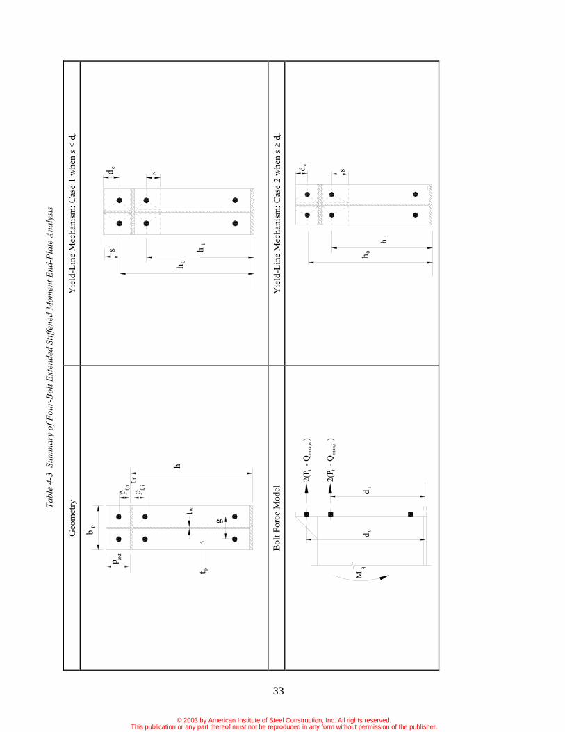
Tabl
e 4-
3 S
umm
ary
of F
our-
Bolt
Exte
nded
Stif
fene
d M
omen
t End
-Pla
te A
naly
sis
Geo
met
ry
Yie
ld-L
ine
Mec
hani
sm; C
ase
1 w
hen
s < d
e
Bol
t For
ce M
odel
Y
ield
-Lin
e M
echa
nism
; Cas
e 2
whe
n s
de
p p
pb
wtpt
p ext
g
h
f, i
f,oft
sd e
h 0
1hs
0dq
Md
1
2(P
- Q
)
2(P
- Q
)
tt
max
,i
max
,o
s
ed
h
h1
0
© 2003 by American Institute of Steel Construction, Inc. All rights reserved.This publication or any part thereof must not be reproduced in any form without permission of the publisher.
33

Tabl
e 4-
3 S
umm
ary
of F
our-
Bolt
Exte
nded
Stif
fene
d M
omen
t End
-Pla
te A
naly
sis(
Con
tinue
d)
Cas
e 1
s < d
e
YtF
MM
ppy
ypl
yn
2
of
0i
f1
of
0i
f1
pp
sh
sp
hg
ps
hs
ph
bY
,,
,,
21
11
12
Not
e: U
se p
f,i =
s, if
pf,i
> s
gb
sp
21
b =
0.9
0 En
d-Pl
ate
Yie
ld
Cas
e 2
s d
e
YtF
MM
ppy
bpl
bn
2
)(
)(
221
11
12
,,
,,
of
e0
if
1o
f0
if
1p
pd
hs
ph
gs
ph
sp
hb
Y Not
e: U
se p
f,i =
s, if
pf,i
> s
gb
sp
21
b =
0.9
0
Bol
t Rup
ture
w
/Pry
ing
Act
ion
)d
)(d
(T)
)(d
(T)d
Q(P
))(
d(T
)dQ
(P)d
Q(P
)dQ
(P
MM
10
b
0b
1m
ax,i
t
1b
0m
ax,o
t
1m
ax,i
t0
max
,ot
qn
22
22
22
2
max
= 0
.75
Bol
t Rup
ture
N
o Pr
ying
Act
ion
)d
)(d
(PM
M1
0t
npn
2
= 0
.75
© 2003 by American Institute of Steel Construction, Inc. All rights reserved.This publication or any part thereof must not be reproduced in any form without permission of the publisher.
34

Tabl
e 4-
4 S
umm
ary
of M
ultip
le R
ow E
xten
ded
Uns
tiffe
ned
1/2
Mom
ent E
nd-P
late
Ana
lysi
s
Geo
met
ry
Yie
ld-L
ine
Mec
hani
sm
Bol
t For
ce M
odel
End-
Plat
eY
ield
YtF
MM
ppy
bpl
bn
2
225.0
75.02
211
11
2,
,,
gp
sh
pp
hg
ph
sh
ph
bY
b2
bi
f1
of
02
if
1p
gb
sp
21
b =
0.9
0
Not
e: U
se p
f,i =
s, if
pf,i
> s
Bol
t Rup
ture
w
/Pry
ing
Act
ion
)d
d)(
d(T
)d
)(d
(T)d
Q(P
)d
)(d
(T)d
Q(P
)d(T
)dQ
(P)d
Q(P
MM
21
0b
20
b1
max
,it
21
b0
max
,ot
2b
1m
ax,i
t0
max
,ot
qn
22
22
22
22
max
=
0.7
5
Bol
t Rup
ture
N
o Pr
ying
Act
ion
)d
d)(
d(P
MM
21
0t
npn
2
= 0
.75
p p
pb
wt
pt
p ext
g
h
f, i
f, o
p b
ft
s
0hh
1
2h
0dq
M
d 2d
1
2(P
- Q
)
2(P
- Q
)m
ax,o
t
max
,it
2Tb
© 2003 by American Institute of Steel Construction, Inc. All rights reserved.This publication or any part thereof must not be reproduced in any form without permission of the publisher.
35
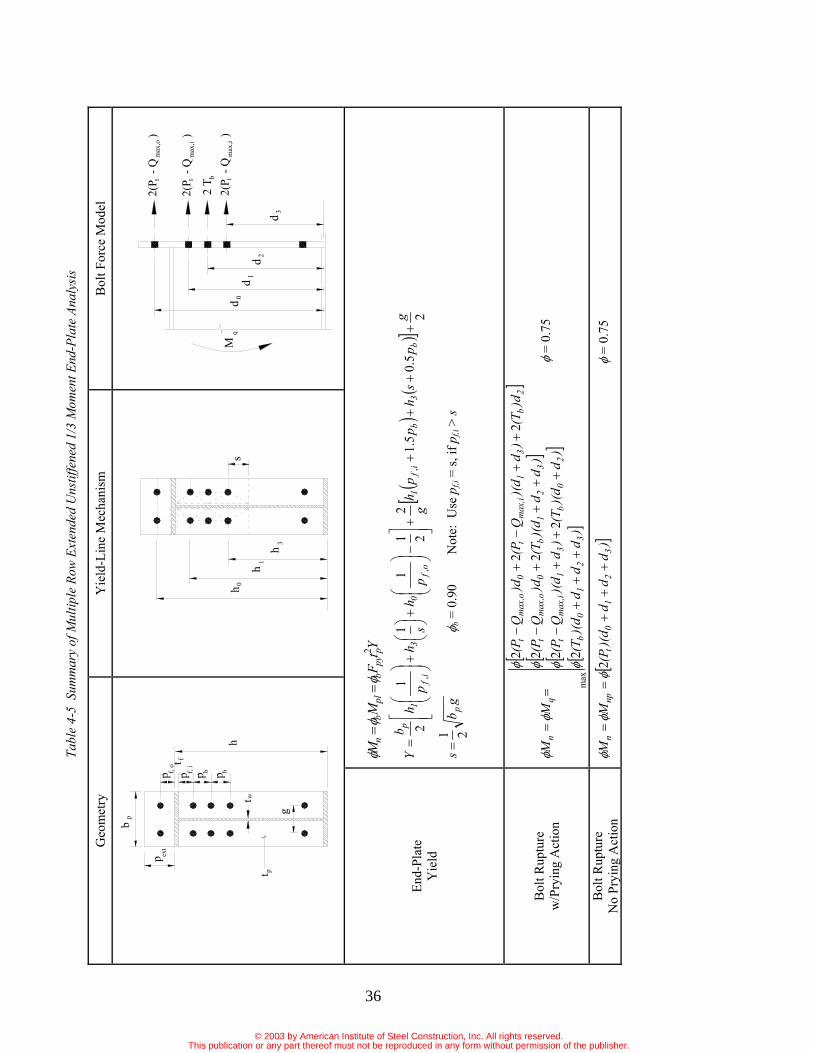
Tabl
e 4-
5 S
umm
ary
of M
ultip
le R
ow E
xten
ded
Uns
tiffe
ned
1/3
Mom
ent E
nd-P
late
Ana
lysi
s
Geo
met
ry
Yie
ld-L
ine
Mec
hani
sm
Bol
t For
ce M
odel
End-
Plat
eY
ield
YtF
MM
ppy
bpl
bn
2
25.0
5.12
211
11
2,
,,
gp
sh
pp
hg
ph
sh
ph
bY
b3
bi
f1
of
03
if
1p
gb
sp
21
b =
0.9
0
N
ote:
Use
pf,i
= s,
if p
f,i >
s
Bol
t Rup
ture
w
/Pry
ing
Act
ion
)d
dd
)(d
(T)
d)(
d(T
)d
)(d
Q(P
)d
d)(
d(T
)dQ
(P)d
(T)
d)(
dQ
(P)d
Q(P
MM
32
10
b
20
b3
1m
ax,i
t
32
1b
0m
ax,o
t
2b
31
max
,it
0m
ax,o
t
qn
22
22
22
22
max
= 0
.75
Bol
t Rup
ture
N
o Pr
ying
Act
ion
)d
dd
)(d
(PM
M3
21
0t
npn
2
=
0.7
5
ht
ptw
ppp
b
p ext
g
p
tf,
o
b
ff,
i
bps
h1
0h
3h
dM
q0
1d
3d
2 T b
d 2
2(P
- Q
)
2(P
- Q
)tt
max
,i
max
,o
t2(
P -
Q
)
max
,i
© 2003 by American Institute of Steel Construction, Inc. All rights reserved.This publication or any part thereof must not be reproduced in any form without permission of the publisher.
36
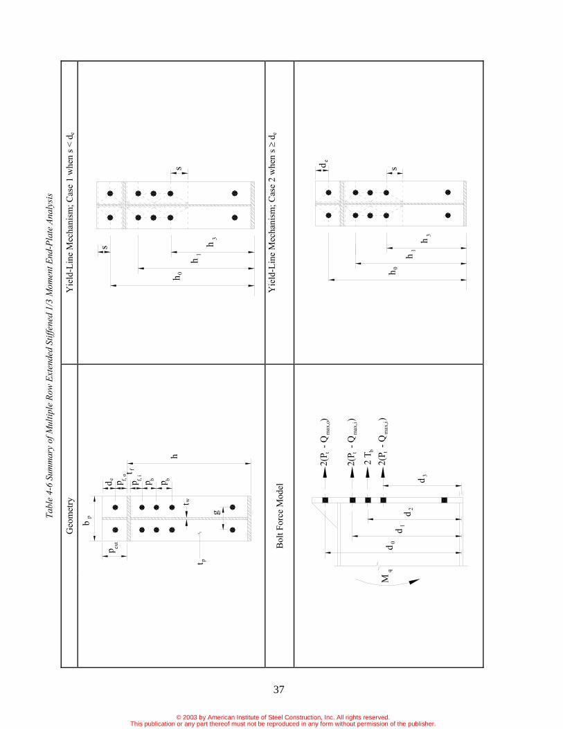
Tabl
e 4-
6 Su
mm
ary
of M
ultip
le R
ow E
xten
ded
Stiff
ened
1/3
Mom
ent E
nd-P
late
Ana
lysi
s
Geo
met
ry
Yie
ld-L
ine
Mec
hani
sm; C
ase
1 w
hen
s < d
e
Bol
t For
ce M
odel
Y
ield
-Lin
e M
echa
nism
; Cas
e 2
whe
n s
de
pp p p
p
ptwt
ext
bp g
bh
ft
bf, i
f, o
ed
s
s
h
h1
3h
0
qM
dd 0
1
d 32d
max
,i2(
P -
Q
)
t
2(P
- Q
)t
2 T b
max
,i
2(P
- Q
)t
max
,o
h
0
1h
h
3
sd e
© 2003 by American Institute of Steel Construction, Inc. All rights reserved.This publication or any part thereof must not be reproduced in any form without permission of the publisher.
37
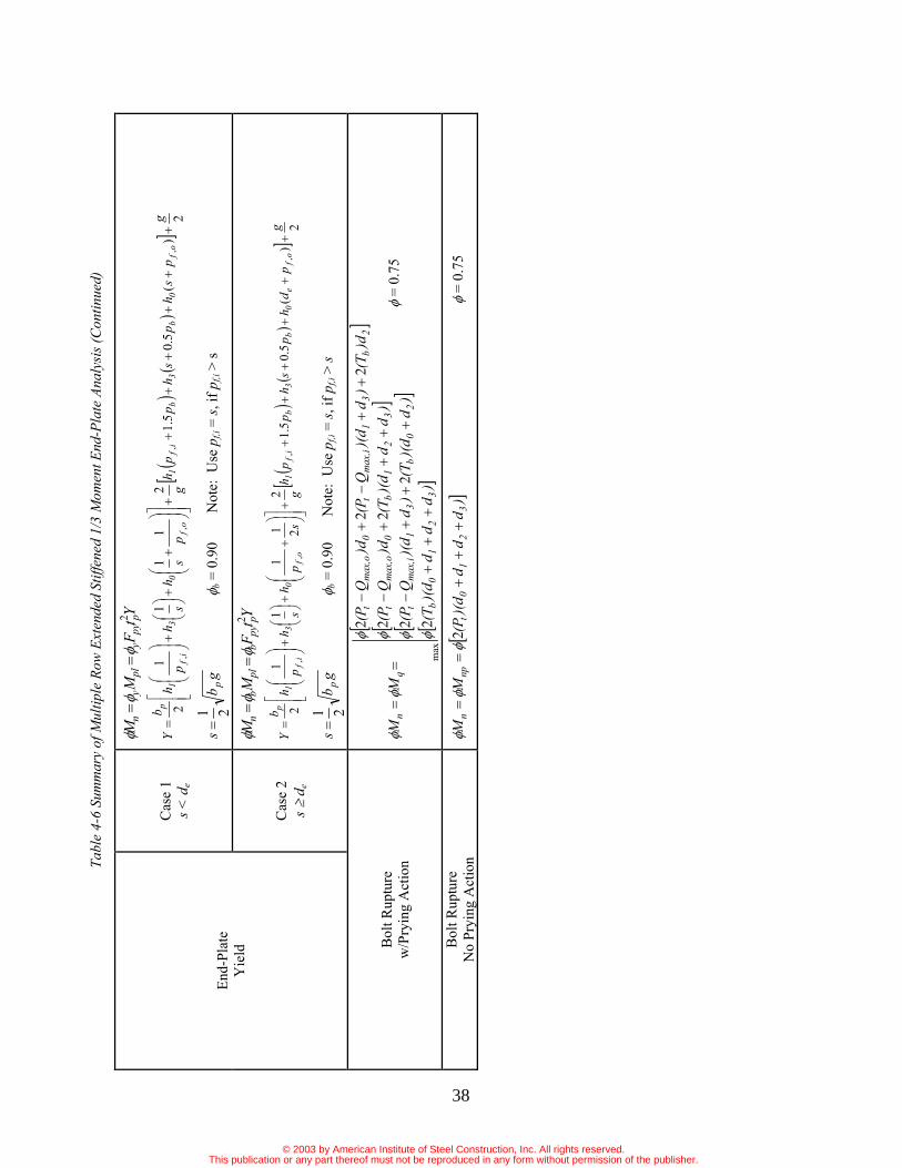
Tabl
e 4-
6 Su
mm
ary
of M
ultip
le R
ow E
xten
ded
Stiff
ened
1/3
Mom
ent E
nd-P
late
Ana
lysi
s (C
ontin
ued)
Cas
e 1
s < d
e
YtF
MM
ppy
ypl
yn
2
2)
(5.0
5.12
11
11
2,
,,
,
gp
sh
ps
hp
ph
gp
sh
sh
ph
bY
of
0b
3b
if
1o
f0
3i
f1
p
gb
sp
21
b = 0
.90
Not
e: U
se p
f,i =
s, if
pf,i
> s
End-
Plat
eY
ield
Cas
e 2
s d
e
YtF
MM
ppy
bpl
bn
2
2)
(5.0
5.12
211
11
2,
,,
,
gp
dh
ps
hp
ph
gs
ph
sh
ph
bY
of
e0
b3
bi
f1
of
03
if
1p
gb
sp
21
b = 0
.90
Not
e: U
se p
f,i =
s, if
pf,i
> s
Bol
t Rup
ture
w
/Pry
ing
Act
ion
)d
dd
)(d
(T)
d)(
d(T
)d
)(d
Q(P
)d
d)(
d(T
)dQ
(P)d
(T)
d)(
dQ
(P)d
Q(P
MM
32
10
b
20
b3
1m
ax,i
t
32
1b
0m
ax,o
t
2b
31
max
,it
0m
ax,o
t
qn
22
22
22
22
max
= 0
.75
Bol
t Rup
ture
N
o Pr
ying
Act
ion
)d
dd
)(d
(PM
M3
21
0t
npn
2
= 0
.75
© 2003 by American Institute of Steel Construction, Inc. All rights reserved.This publication or any part thereof must not be reproduced in any form without permission of the publisher.
38

39
Table 4-7 Tested Parameter Range for Extended End-Plate Connections
Parameter Low (in.) High (in.)
pf 1 221 (a)
pext 221 5
81
g 243 7
h 1543 24(b)
bp 6 1041
tf 83 1
aA large inner pitch, pf,i, of 5 in. for the multiple row extended unstiffened 1/2 connection was also verified as reported in Sumner and Murray (2001). bFor the multiple row extended connections, the upper limit for depth is 62 in.
4.2 Design ExamplesThe following design examples are in the LRFD format. The same procedures apply for ASD design if the ASD moments are first converted to factored moments as ex-plained in Section 2.5.2.
4.2.1 Four-Bolt Extended Unstiffened Moment End-Plate Connection (Table 4-2) The required end-plate thickness and bolt diameter for an end-plate connection with the geometry shown below and a required factored moment of 1,750 k-in is to be deter-mined. The end-plate material is A572 Gr 50, the bolts are snug-tightened A325, and the connection is used in rigid
frame construction as assumed in the frame analysis. Both LRFD design procedures are illustrated. Geometric Design Data
bp = bf = 8 in. tf = 3/8 in. g = 3 in. pf,i = 1 3/4 in. pf,o = 2 1/2 in. pext = 5 in. h = 24 in.
Calculate:0.1r for extended connections
d0 = 24+2.5-(0.375/2) = 26.3125 in. h0 = 26.5 in. d1 = 24-0.375-1.75-(0.375/2) = 21.6875 in. h1 = 21.875 in.
Design Procedure 1 (Thick End-Plate and Smaller Diameter Bolts):
1.) Solve for the required bolt diameter assuming no pry-ing action,
.in59.0688.21313.269075.0
175022,
nt
ureqdb dF
Md
Use db = 5/8 in.
2.) Solve for the required end-plate thickness, tp,reqd,
in.45.20.30.821
21 gbs p
pf,i = 1.75 in. s use pf,i = 1.75 in.
sphgp
hsp
hb
Y if1of
0if
1p
,,,
221111
2
.in4.18745.275.1875.210.3
221
5.215.26
45.21
75.11875.21
20.8
k6.274/90625.04/ 22FdP tbt
in.k1987
)]688.21313.26)(6.27(2[75.02
-dPM ntnp
tp g
p
1dd 0
ext
wt
pf, i
f, op
ft
hh
h 1
0
pb
s
© 2003 by American Institute of Steel Construction, Inc. All rights reserved.This publication or any part thereof must not be reproduced in any form without permission of the publisher.

40
in.51.04.1875090.0
19870.111.111.1 r
YFM
tpyb
npp,reqd
Use tp = 9/16 in.
Design Procedure 2 (Thin End-Plate and Larger Di-ameter Bolts):
1.) Determine the required plate thickness,
in.46.04.1875090.0
17500.1YF
Mtpyb
urp,reqd
Use tp = 1/2 in.
2.) Select a trial bolt diameter, db, and calculate the maximum prying forces, Qmax,i and Qmax,o .
Try db = 0.75 in.
.in19.3
16/175.02/0.816/12/ bp dbw
in.01.1085.075.0/50.0682.3
085.0/682.33
3bpi dta
if
tbppyp
i p
Fdw
bFt
F,
32
4
880.0
285.0
k8.12)75.1(4
89075.019.380.0
20.885.05050.0
32
22
2
34 p
ipy
i
pmax,i tw
FFatw
Q
k48.9
50.019.38.12350
01.1450.019.3
22
2
and for the outer bolts,
.in01.1
.in5.25.25or.in01.1of.min ,
o
ofexto
a
ppa
k75.8)5.2/75.1(8.12)/( ,, ofifio ppFF
22
2
34 p
opy
o
pmax,o tw
FFatw
Q
k69.9
50.019.375.8350
01.1450.019.3
22
2
3.) Calculate the connection design strength for the limit state of bolt rupture with prying action,
k8.394/9075.04/ 22FdP tbt
)d)(d(T))(d(T)dQ(P))(d(T)dQ(P
)dQ(P)dQ(P
M
10b
0b1max,it
1b0max,ot
1max,it0max,ot
q
2222222
max
For snug-tight bolts, Tb is 50% of Table J3.1 value = 0.50(28) = 14 k
.ink1008])688.21313.26)(14(2[75.0.ink1539
])313.26)(14(2)688.21)(48.98.39(2[75.0.ink1644
])688.21)(14(2313.26)69.98.39(2[75.0.ink2175688.2148.98.392
313.2669.98.39275.0
max --
-
-
M q
4.) Check that Mq > Mu. If necessary, adjust the bolt di-ameter until Mq is greater than Mu.
17502175qM k-in., so the trial bolt, 3/4 in dia. is ok.
Note: A check (not shown) of 5/8 in. bolt confirms that 3/4 in. is required.
Summary: tp = 9/16 in. db = 5/8 in.
Summary: tp = 1/2 in. db = 3/4 in.
© 2003 by American Institute of Steel Construction, Inc. All rights reserved.This publication or any part thereof must not be reproduced in any form without permission of the publisher.
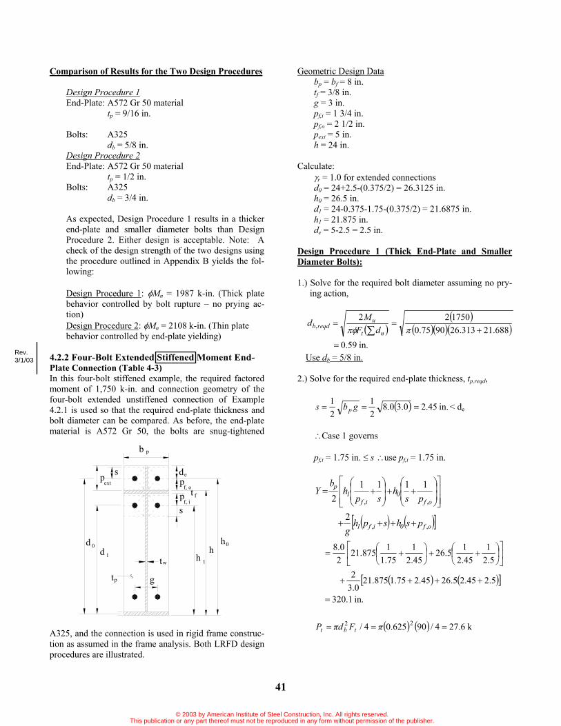
41
Comparison of Results for the Two Design Procedures
Design Procedure 1End-Plate: A572 Gr 50 material
tp = 9/16 in.
Bolts: A325 db = 5/8 in.
Design Procedure 2End-Plate: A572 Gr 50 material
tp = 1/2 in. Bolts: A325
db = 3/4 in.
As expected, Design Procedure 1 results in a thicker end-plate and smaller diameter bolts than Design Procedure 2. Either design is acceptable. Note: A check of the design strength of the two designs using the procedure outlined in Appendix B yields the fol-lowing:
Design Procedure 1: Mn = 1987 k-in. (Thick plate behavior controlled by bolt rupture – no prying ac-tion) Design Procedure 2: Mn = 2108 k-in. (Thin plate behavior controlled by end-plate yielding)
4.2.2 Four-Bolt Extended Stiffened Moment End-Plate Connection (Table 4-3) In this four-bolt stiffened example, the required factored moment of 1,750 k-in. and connection geometry of the four-bolt extended unstiffened connection of Example 4.2.1 is used so that the required end-plate thickness and bolt diameter can be compared. As before, the end-plate material is A572 Gr 50, the bolts are snug-tightened
A325, and the connection is used in rigid frame construc-tion as assumed in the frame analysis. Both LRFD design procedures are illustrated.
Geometric Design Databp = bf = 8 in. tf = 3/8 in. g = 3 in. pf,i = 1 3/4 in. pf,o = 2 1/2 in. pext = 5 in. h = 24 in.
Calculate:r = 1.0 for extended connections
d0 = 24+2.5-(0.375/2) = 26.3125 in. h0 = 26.5 in. d1 = 24-0.375-1.75-(0.375/2) = 21.6875 in. h1 = 21.875 in. de = 5-2.5 = 2.5 in.
Design Procedure 1 (Thick End-Plate and Smaller Diameter Bolts):
1.) Solve for the required bolt diameter assuming no pry-ing action,
.in59.0688.21313.269075.0
175022,
nt
ureqdb dF
Md
Use db = 5/8 in.
2.) Solve for the required end-plate thickness, tp,reqd,
in.45.20.30.821
21 gbs p < de
Case 1 governs
pf,i = 1.75 in. s use pf,i = 1.75 in.
of0if1
of0
if1
p
pshsphg
psh
sph
bY
,,
,,
2
11112
5.21
45.215.26
45.21
75.11875.21
20.8
.in1.320
5.245.25.2645.275.1875.210.3
2
k6.274/90625.04/ 22 FdP tbt
pextp
1
dd
0
pt
1wt
g
h
s
f, o
f, ip ft
h0h
pb
s de
Rev.3/1/03
© 2003 by American Institute of Steel Construction, Inc. All rights reserved.This publication or any part thereof must not be reproduced in any form without permission of the publisher.

42
.ink1987
)]688.21313.26)(6.27(2[75.02 ntnp dPM
.in39.0
1.3205090.019870.111.111.1 r
YFM
tpyb
npp,reqd
Use tp = 7/16 in.
Design Procedure 2 (Thin End-Plate and Larger Di-ameter Bolts):
1.) Determine the required plate thickness,
.in35.01.3205090.0
17500.1YF
Mtpyb
urp,reqd
Use tp = 3/8 in.
2.) Select a trial bolt diameter, db, and calculate the maximum prying forces, Qmax,i and Qmax,o
Try db = 0.75 in.
.in19.3
16/175.02/0.816/12/ bp dbw
.in38.0085.075.0/375.0682.3
085.0/682.33
3bpi dta
if
tbppyp
i p
Fdw
bFt
F,
32
4
880.0
285.0
k11.8)75.1(4
89075.019.380.0
20.885.050375.0
32
22
2
34 p
ipy
i
pmax,i tw
FFatw
Q
k3.14
375.019.311.8350
38.04375.019.3
22
2
and for the outer bolts,
.in38.0
.in5.25.25or.in38.0ofmin ,
o
ofexto
a
ppa
k68.5)5.2/75.1(11.8)/( ,, ofifio ppFF
22
2
34 p
opy
o
pmax,o tw
FFatw
Q
k6.14
375.019.368.5350
38.04375.019.3
22
2
3.) Calculate the connection design strength for the limit state of bolt rupture with prying action,
k8.394/9075.04/ 22 FdP tbt
)d)(d(T))(d(T)dQ(P))(d(T)dQ(P
)dQ(P)dQ(P
M
10b
0b1max,it
1b0max,ot
1max,it0max,ot
q
2222222
max
For snug-tight bolts, Tb is 50% of Table J3.1 value = 0.50(28) = 14 k
.ink1008])688.21313.26)(14(2[75.0.ink1382
])313.26)(14(2)688.21)(3.148.39(2[75.0.ink1450
])688.21)(14(2313.26)6.148.39(2[75.0.ink1824688.213.148.392
313.266.148.39275.0
max --
-
-
M q
4.) Check that Mq > Mu. If necessary, adjust the bolt di-ameter until Mq is greater than Mu.
17501824qM k-in., so the trial bolt, 3/4 in. dia. is ok.
Summary: tp = 7/16 in. db = 5/8 in.
Summary: tp = 3/8 in. db = 3/4 in.
© 2003 by American Institute of Steel Construction, Inc. All rights reserved.This publication or any part thereof must not be reproduced in any form without permission of the publisher.

43
Comparison of Results for the Two Design Procedures
Design Procedure 1End-Plate: A572 Gr 50 material
tp = 7/16 in. Bolts: A325
db = 5/8 in. Design Procedure 2End-Plate: A572 Gr 50 material
tp = 3/8 in. Bolts: A325
db = 3/4 in.
As expected, Design Procedure 1 results in a thicker end-plate and smaller diameter bolts than Design Procedure 2. Either design is acceptable. Note: A check of the design strength of the two designs using the procedure outlined in Appendix B yields the fol-lowing:
Design Procedure 1: Mn = 1987 k-in. (Thick plate behavior controlled by bolt rupture – no prying ac-tion) Design Procedure 2: Mn = 1824 k-in. (Thin plate behavior controlled by bolt rupture with prying ac-tion)
A comparison of Examples 4.2.1 and 4.2.2 shows that the addition of the stiffener reduces the end-plate thickness by 1/8 inch for both design procedures. The bolt size is unaffected.
4.2.3 Multiple Row Extended Unstiffened 1/2 Mo-ment End-Plate Connection (Table 4-4) The required end-plate thickness and bolt diameter for an end-plate connection with the geometry shown below are to be determined for a required factored moment of 2,200 k-in. and a factored axial tension of 16.9 kips. The end-
plate material is A572 Gr 50, the bolts are fully tightened A325, and the connection is used in rigid frame construc-tion as assumed in the frame analysis. Both LRFD design procedures are illustrated. Geometric Design Data
bp = bf = 8 in tf = 3/8 in g = 3 in pf,i = 1 3/4 in pf,o = 2 1/2 in pb = 2 1/2 in pext = 5 in h = 24 in
Calculate:r = 1.0 for extended connections
d0 = 24+2.5-(0.375/2) = 26.3125 in. h0 = 26.5 in. d1 = 24-0.375-1.75-(0.375/2) = 21.6875 in. h1 = 21.875 in. d2 = 24-0.375-1.75-2.5-(0.375/2) = 19.1875 in. h2 = 19.375
Axial Load TreatmentThe procedure is to convert the factored axial load into an equivalent moment that will be added to the factored con-nection moment for axial tension, or subtracted from the factored connection moment for axial compression. For this example the axial load is tension and will add to the flange force at the tension flange. The connection moment is increased.
Tu = 16.9 kips h-tf = 24 - 0.375 = 23.625 in. Maxial = (16.9/2)(23.625) = 200 k-in. Total factored moment, Mu = 2200 + 200 = 2400 k-in.
f, i
d 0
1dd 2
pt
t
g
w
bp
extp
b p
pf, o
p t f
s
2
hh 1
h0
h
M qAxial Tension, P
P/2
h - t f
© 2003 by American Institute of Steel Construction, Inc. All rights reserved.This publication or any part thereof must not be reproduced in any form without permission of the publisher.

44
Design Procedure 1 (Thick End-Plate and Smaller Diameter Bolts):
1.) Solve for the required bolt diameter assuming no pry-ing action,
.in58.0188.19688.21313.269075.0
24002
2,
nt
ureqdb dF
Md
Use db = 5/8 in.
2.) Solve for the required end-plate thickness, tp,reqd,
45.2)0.3(0.821
21 gbs p in.
pf,i = 1.75 in s use pf,i = 1.75 in.
2..2
21
2
,
,,
gp250shp750phg
ph
sh
phb
Y
b2bif1
of
02
if
1p
21
2.526.5
2.4519.375
1.7521.875
28.0
in.216.12
3.02.50.252.4519.375
2.50.751.7521.8753.02
k6.274/90625.04/ 22 FdP tbt
.ink2782)]188.19688.21313.26)(6.27(2[75.0
2 ntnp dPM
.in56.0
1.2165090.027820.111.111.1 r
YFM
tpyb
npp,reqd
Use tp = 9/16 in.
Design Procedure 2 (Thin End-Plate and Larger Di-ameter Bolts):
1.) Determine the required plate thickness,
.in50.01.2165090.0
24000.1YF
Mtpyb
urp,reqd
Use tp = 1/2 in.
2.) Select a trial bolt diameter, db, and calculate the maximum prying forces, Qmax,i and Qmax,o .
Try db = 3/4 in.
.in19.3
16/175.02/0.816/12/ bp dbw
.in01.1085.075.0/50.0682.3
085.0/682.33
3bpi dta
if
tbppyp
i p
Fdw
bFt
F,
32
4
880.0
285.0
k8.12)75.1(4
89075.019.380.0
20.885.05050.0
32
22
2
34 p
ipy
i
pmax,i tw
FFatw
Q
k48.9
50.019.38.12350
01.1450.019.3
22
2
and for the outer bolts,
.in01.1
.in5.25.25or.in01.1ofmin ,
o
ofexto
a
ppa
k96.8)5.2/75.1(8.12)/( ,, ofifio ppFF
22
2
34 p
opy
o
pmax,o tw
FFatw
QSummary: tp = 9/16 in. db = 5/8 in.
© 2003 by American Institute of Steel Construction, Inc. All rights reserved.This publication or any part thereof must not be reproduced in any form without permission of the publisher.
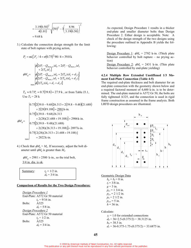
45
k68.9
50.019.396.8350
01.1450.019.3
22
2
3.) Calculate the connection design strength for the limit state of bolt rupture with prying action,
k8.394/9075.04/ 22FdP tbt
)dd)(d(T)d)(d(T)dQ(P)d)(d(T)dQ(P
)d(T)dQ(P)dQ(P
M
210b
20b1max,it
21b0max,ot
2b
1max,it0max,ot
q
22222
222
max
k9.278.397.07.0 tb PT , or from Table J3.1, Use Tb = 28 k
.ink2822])188.19688.21313.26)(28(2[75.0
.ink2897)188.19313.26)(28(2)688.21)(48.98.39(275.0
.ink2906)188.19688.21)(28(2313.26)68.98.39(275.0
.ink2981188.19282688.2148.98.392313.2668.98.39275.0
max -
-
-
-
M q
4.) Check that Mq > Mu. If necessary, adjust the bolt di-ameter until Mq is greater than Mu.
25002981qM k-in., so the trial bolt, 3/4 in. dia. is ok.
Comparison of Results for the Two Design Procedures:
Design Procedure 1End-Plate: A572 Gr 50 material
tp = 9/16 in. Bolts: A325
db = 5/8 in. Design Procedure 2End-Plate: A572 Gr 50 material
tp = 1/2 in. Bolts: A325
db = 3/4 in.
As expected, Design Procedure 1 results in a thicker end-plate and smaller diameter bolts than Design Procedure 2. Either design is acceptable. Note: A check of the design strength of the two designs using the procedure outlined in Appendix B yields the fol-lowing:
Design Procedure 1: Mn = 2782 k-in. (Thick plate behavior controlled by bolt rupture – no prying ac-tion) Design Procedure 2: Mn = 2431 k-in. (Thin plate behavior controlled by end-plate yielding)
4.2.4 Multiple Row Extended Unstiffened 1/3 Mo-ment End-Plate Connection (Table 4-5) The required end-plate thickness and bolt diameter for an end-plate connection with the geometry shown below and a required factored moment of 4,600 k-in. is to be deter-mined. The end-plate material is A572 Gr 50, the bolts are fully tightened A325, and the connection is used in rigid frame construction as assumed in the frame analysis. Both LRFD design procedures are illustrated.
Geometric Design Databp = bf = 8 in. tf = 3/8 in. g = 3 in. pf,i = 1 3/4 in. pf,o = 2 1/2 in. pb = 2 1/2 in. pext = 5 in. h = 36 in.
Calculate:r = 1.0 for extended connections
d0 = 36+2.5-(0.375/2) = 38.3125 in. h0 = 38.5 in. d1 = 36-0.375-1.75-(0.375/2) = 33.6875 in.
Summary: tp = 1/2 in. db = 3/4 in.
0d
tpd 3
dd
1
2
extp
g
wt
sbp
h
ftpf, i
bp
f, op
pb
0h
h 1
3h
© 2003 by American Institute of Steel Construction, Inc. All rights reserved.This publication or any part thereof must not be reproduced in any form without permission of the publisher.

46
h1 = 33.875 in. d2 = 36-0.375-1.75-2.5-(0.375/2) = 31.1875 in. h2 = 31.375 in. d3 = 36-0.375-1.75-2.5-2.5-(0.375/2) = 28.6875 in. h3 = 28.875 in.
Design Procedure 1 (Thick End-Plate and Smaller Diameter Bolts):
1.) Solve for the required bolt diameter assuming no pry-ing action,
nt
ureqdb dF
Md 2,
.in57.0688.28188.31688.33313.389075.0
46002
Use db = 5/8 in.
2.) Solve for the required end-plate thickness, tp,reqd,
45.2)0.3(0.821
21 gbs p in.
pf,i = 1.75 in s use pf,i = 1.75 in.
2..2
21111
2
,
,,
gp50shp51phg
ph
sh
ph
bY
b3bif1
of03
if1
p
.in3.38020.3))5.2(5.045.2(6875.28
))5.2(5.175.1(875.330.3
221
5.215.38
45.216875.28
75.11875.33
20.8
k6.274/90625.04/ 22 FdP tbt
in.k5460)]688.28188.31688.33313.38)(6.27(2[75.0
2 ntnp dPM
.in60.0
3.3805090.054600.111.111.1 r
YFM
tpyb
npp,reqd
Use tp = 5/8 in.
Design Procedure 2 (Thin End-Plate and Larger Di-ameter Bolts):
1.) Determine the required plate thickness,
.in52.03.3805090.0
46000.1YF
Mtpyb
urp,reqd
Use tp = 9/16 in.
2.) Select a trial bolt diameter, db, and calculate the maximum prying forces, Qmax,i and Qmax,o .
Try db = 3/4 in.
.in19.3
16/175.02/0.816/12/ bp dbw
.in47.1085.075.0/5625.0682.3
085.0/682.33
3bpi dta
if
tbppyp
i p
Fdw
bFt
F,
32
4
880.0
285.0
k6.15)75.1(4
89075.019.380.0
20.885.0505625.0
32
22
2
34 p
ipy
i
pmax,i tw
FFatw
Q
k18.8
5625.019.36.15350
47.145625.019.3
22
2
and for the outer bolts,
in.47.1
.in5.25.25orin47.1ofmin ,
o
ofexto
a
ppa
Summary: tp = 5/8 in. db = 5/8 in.
© 2003 by American Institute of Steel Construction, Inc. All rights reserved.This publication or any part thereof must not be reproduced in any form without permission of the publisher.
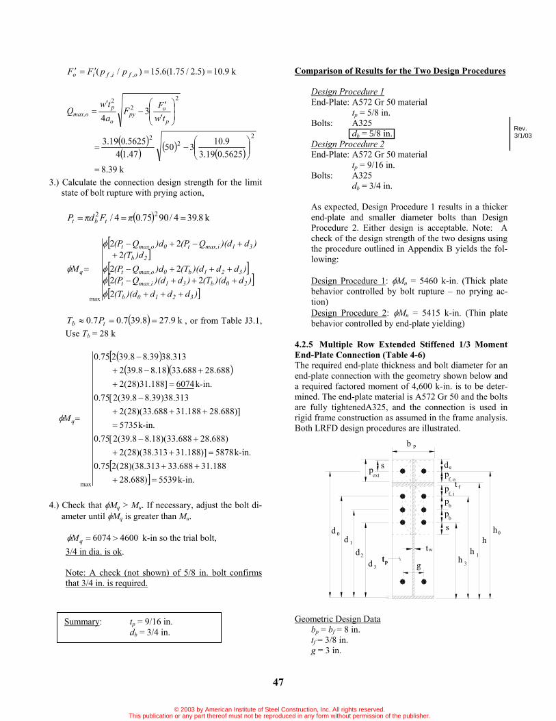
47
k9.10)5.2/75.1(6.15)/( ,, ofifio ppFF
22
2
34 p
opy
o
pmax,o tw
FFatw
Q
k39.8
5625.019.39.10350
47.145625.019.3
22
2
3.) Calculate the connection design strength for the limit state of bolt rupture with prying action,
k8.394/9075.04/ 22FdP tbt
)ddd)(d(T)d)(d(T)d)(dQ(P
)dd)(d(T)dQ(P)d(T
)d)(dQ(P)dQ(P
M
3210b
20b31max,it
321b0max,ot
2b
31max,it0max,ot
q
222
222
22
max
k9.278.397.07.0 tb PT , or from Table J3.1, Use Tb = 28 k
.ink5539)688.28188.31688.33313.38)(28(275.0
.ink5878)]188.31313.38)(28(2)688.28688.33)(18.88.39(2[75.0
.ink5735)]688.28188.31688.33)(28(2
313.38)39.88.39(2[75.0.ink6074]188.31)28(2
688.28688.3318.88.392313.3839.88.39275.0
max -
-
-
-
M q
4.) Check that Mq > Mu. If necessary, adjust the bolt di-ameter until Mq is greater than Mu.
46006074qM k-in so the trial bolt, 3/4 in dia. is ok.
Note: A check (not shown) of 5/8 in. bolt confirms that 3/4 in. is required.
Comparison of Results for the Two Design Procedures
Design Procedure 1End-Plate: A572 Gr 50 material
tp = 5/8 in. Bolts: A325
db = 5/8 in. Design Procedure 2End-Plate: A572 Gr 50 material
tp = 9/16 in. Bolts: A325
db = 3/4 in.
As expected, Design Procedure 1 results in a thicker end-plate and smaller diameter bolts than Design Procedure 2. Either design is acceptable. Note: A check of the design strength of the two designs using the procedure outlined in Appendix B yields the fol-lowing:
Design Procedure 1: Mn = 5460 k-in. (Thick plate behavior controlled by bolt rupture – no prying ac-tion) Design Procedure 2: Mn = 5415 k-in. (Thin plate behavior controlled by end-plate yielding)
4.2.5 Multiple Row Extended Stiffened 1/3 Moment End-Plate Connection (Table 4-6) The required end-plate thickness and bolt diameter for an end-plate connection with the geometry shown below and a required factored moment of 4,600 k-in. is to be deter-mined. The end-plate material is A572 Gr 50 and the bolts are fully tightenedA325, and the connection is used in rigid frame construction as assumed in the frame analysis. Both LRFD design procedures are illustrated.
Geometric Design Databp = bf = 8 in. tf = 3/8 in. g = 3 in.
Summary: tp = 9/16 in. db = 3/4 in.
pt g
tw
pb
d
p t
pb
f, i
pf, o
e
b p
f
s
s
3
hh 1
h0
h
0d1d
3dd2
pt
extp
Rev.3/1/03
© 2003 by American Institute of Steel Construction, Inc. All rights reserved.This publication or any part thereof must not be reproduced in any form without permission of the publisher.

48
pf i = 1 3/4 in. pf,o = 2 1/2 in pb = 2 1/2 in. pext = 5 in. h = 36 in.
Calculate:r = 1.0 for extended connections
d0 = 36+2.5-(0.375/2) = 38.3125 in. h0 = 38.5 in. d1 = 36-0.375-1.75-(0.375/2) = 33.6875 in. h1 = 33.875 in. d2 = 36-0.375-1.75-2.5-(0.375/2) = 31.1875 in. h2 = 31.375 in. d3 = 36-0.375-1.75-2.5-2.5-(0.375/2) = 28.6875 in. h3 = 28.875 in. de = 5-2.5 = 2.5 in.
Design Procedure 1 (Thick End-Plate and Smaller Diameter Bolts):
1.) Solve for the required bolt diameter assuming no pry-ing action,
nt
ureqdb dF
Md 2,
.in57.0688.28188.31688.33313.389075.0
46002
Use db = 5/8 in.
2.) Solve for the required end-plate thickness, tp,reqd,
45.2)0.3(0.821
21 gbs p in. < de
Case 1 governs.
pf,i = 1.75 in s use pf,i = 1.75 in.
2..2
11112
,,
,,
gpshp50shp51phg
psh
sh
ph
bY
of0b3bif1
of03
if1
p
5.21
45.215.38
45.21875.28
75.11875.33
20.8
.in0.57320.35.245.25.38
5.25.045.2875.285.25.175.1875.330.3
2
k6.274/90625.04/ 22 FdP tbt
.ink5460)]688.28188.31688.33313.38)(6.27(2[75.0
2 ntnp dPM
.in48.05735090.0
54600.111.111.1 r
YFM
tpyb
npp,reqd
Use tp = 1/2 in.
Design Procedure 2 (Thin End-Plate and Larger Di-ameter Bolts):
1.) Determine the required plate thickness,
.in42.05735090.0
46000.1YF
Mtpyb
urp,reqd
Use tp = 7/16 in.
2.) Select a trial bolt diameter, db, and calculate the maximum prying forces, Qmax,i and Qmax,o .
Try db = 3/4 in.
.in19.3
16/175.02/0.816/12/ bp dbw
.in65.0085.075.0/4375.0682.3
085.0/682.33
3bpi dta
if
tbppyp
i p
Fdw
bFt
F,
32
4
880.0
285.0
Summary: tp = 1/2 in. db = 5/8 in.
© 2003 by American Institute of Steel Construction, Inc. All rights reserved.This publication or any part thereof must not be reproduced in any form without permission of the publisher.

49
k3.10)75.1(4
89075.019.380.0
20.885.0504375.0
32
22
2
34 p
ipy
i
pmax,i tw
FFatw
Q
k4.11
4375.019.33.10350
65.044375.019.3
22
2
and for the outer bolts,
in.65.0
.in5.25.25orin.65.0ofmin ,
o
ofexto
a
ppa
k21.7)5.2/75.1(3.10)/( ,, ofifio ppFF
22
2
34 p
opy
o
pmax,o tw
FFatw
Q
k6.11
4375.019.321.7350
65.044375.019.3
22
2
3.) Calculate the connection design strength for the limit state of bolt rupture with prying action,
k8.394/9075.04/ 22FdP tbt
)ddd)(d(T)d)(d(T)d)(dQ(P
)dd)(d(T)dQ(P)d(T
d)(dQ(P)dQ(P
M
3210b
20b31max,it
321b0max,ot
2b
31max,it0max,ot
q
222
222
)22
max
k9.278.397.07.0 tb PT , or from Table J3.1, Use Tb = 28 k
.ink5539])688.28188.31688.33313.38)(28(2[75.0
.ink5576])188.31313.38)(28(2)688.28688.33)(4.118.39(2[75.0
.ink5550])688.28188.31688.33)(28(2
313.38)6.118.39(2[75.0.ink5588]188.31)28(2
688.28688.334.118.392313.386.118.39275.0
max -
-
-
-
M q
4.) Check that Mq > Mu. If necessary, adjust the bolt di-ameter until Mq is greater than Mu.
46005588qM k-in. so the trial bolt, 3/4 in dia. is ok.
Comparison of Results for the Two Design Procedures
Design Procedure 1End-Plate: A572 Gr 50 material
tp = 1/2 in. Bolts: A325
db = 5/8 in. Design Procedure 2End-Plate: A572 Gr 50 material
tp = 7/16 in. Bolts: A325
db = 3/4 in.
As expected, Design Procedure 1 results in a thicker end-plateand smaller diameter bolts than Design Pro-cedure 2. Either design is acceptable. Note: A check of the designstrength of the two designs using the procedure outlinedin Appendix B yields the follow-ing:
Design Procedure 1: Mn = 5460 k-in. (Thick plate-behavior controlled by bolt rupture – no prying ac-tion) Design Procedure 2: Mn = 4935 k-in. (Thin plate behavior controlled by end-plate yielding)
A comparison of Examples 4.2.4 and 4.2.5 shows that the addition of the stiffener reduces the end-plate thickness by 1/8 inch for both design procedures. The bolt size is unaffected.
Summary: tp = 7/16 in. db = 3/4 in.
© 2003 by American Institute of Steel Construction, Inc. All rights reserved.This publication or any part thereof must not be reproduced in any form without permission of the publisher.

© 2003 by American Institute of Steel Construction, Inc. All rights reserved.This publication or any part thereof must not be reproduced in any form without permission of the publisher.

51
Chapter 5 GABLE FRAME PANEL ZONE DESIGN 5.1 IntroductionThe panel zone plate of a gable frame is defined as the web plate in the knee area. The knee area is defined as that portion of the frame that connects a column section to a rafter section, Figure 5-1. The panel zone plate is stiff-ened on two sides by the continuation of the outside col-umn and rafter flanges. A full depth rafter web stiffener (which may be a moment connection end-plate), ap-proximately aligned with the inside column flange as shown in Figure 5-2, stiffens the third side. Either a full depth or partial depth column web stiffener, approxi-mately aligned with the inside rafter flange as shown in Figures 5-2a and 5-2b, respectively, is connected to the fourth side. A full depth stiffener is welded to both the inside and outside column flanges; a partial depth stiff-ener is welded only to the inside column flange.
Possible limit states for panel zone plates are elastic plate buckling, inelastic plate buckling, post-buckling strength due to formation of a tension field (as shown in Figure 5-3) and plate yielding. All of these limit states are possible for negative moment loading (tension on the out-side of the knee area) if full depth stiffeners are used. It has been shown that tension field action will not develop if partial depth stiffeners are used (Murray 1986) or for positive moment loading (Young and Murray 1996).
For a buckled web plate to develop tension field ac-tion, the tension field must be anchored at both ends, loca-tions A and B in Figure 5-3 for negative moment. Tests have shown that if a partial depth stiffener is used the tension field will not anchor at location A and the addi-tional strength associated with a tension field will not develop. Similarly, anchorage at the outside corner of the knee area is not sufficient to fully develop a tension field if positive moment exits.
The AISC ASD and LRFD Specifications have provi-sions only for the design of panel zone web plates in beam-to-column joints in multi-story frames. The as-sumed limit state for these rules is shear yielding; plate buckling checks are not required. However, plate buck-ling is usually the controlling limit state of panel zone plates in gable frames using built-up columns and rafters.
Design rules for such plates have been developed (Murray 1986) as presented in LRFD and ASD formats in the fol-lowing sections.
Use of these design rules requires that the combined width of the panel zone web stiffeners be approximately the same as the rafter flange width and of the same thick-ness as the rafter flange. Stiffener-to-column flange welds must be large enough to develop the yield strength of the portion of the stiffener in contact with the column flange (stiffener width minus clip required for web-to-column flange clearance). The stiffener-to-column web weld must
Knee Area
Figure 5-1 Knee area of gable frame.
Knee Area
Partial Depth Column Web Stiffener
Panel Zone Plate V (ASD)
V (LRFD)U
P (LRFD)P (ASD)
U
M (LRFD)U
M (ASD)
Figure 5-2b Knee with partial depth stiffener.
Partial Depth Column Web Stiffener
Panel Zone Plate
Panel Zone Plate
Full Depth Column Web Stiffener
P (ASD)
V (LRFD)V (ASD)
P (LRFD)
M (ASD)M (LRFD)U
U
U
Figure 5-2a Knee with full depth stiffener.
Full Depth Column Web Stiffener
Panel Zone Plate
Figure 5-3 Panel zone tension field.
Tension Field
A
B
© 2003 by American Institute of Steel Construction, Inc. All rights reserved.This publication or any part thereof must not be reproduced in any form without permission of the publisher.

52
be sufficient to resist the yield strength of the stiffener. The following design procedures are restricted to ga-
ble frame panel zones and engineering judgment is re-quired for other applications; however, these procedures are not applicable to panel zones in high-rise buildings.
5.2 LRFD Rules and Example Calculations 5.2.1 LRFD RulesPanel zone plates in the gable frames can be designed using AISC LRFD rules for webs of plate girders. When using these equations the parameter h is the depth of the panel zone plate at the rafter side (see Figure 5-4). The required shear strength is calculated from:
2uu
uP
hMV (5-1)
where Mu = required flexural strength Pu = required thrust
Both Mu and Pu at the rafter face of the panel zone are determined using factored loads.
The design shear strength, vVn, is determined accord-ing to Section A-G3 of the AISC LRFD Specification as follows:
1. Panel Zone Subject to Negative Moment and with Full Depth Column Web Stiffeners
a) For yw
vywvw F
kFEkh/t 187/10.1
)6.0( ywwvnv FAV (5-2)
b) For yw
vywvw F
kFEkh/t 187/10.1
2115.1
1)6.0(ha
CCFAVv
vvywwvnv (5-3)
where v = 0.90
Aw = av×twav = width of panel zone at the column top (see
Figure 5-4) tw = panel zone plate thickness Fyw = yield stress of the panel plate material
kv = 5 + 25hav
Cv = shear coefficient determined as follows:
i) For ywvw
ywv FEkthFEk /37.1/10.1
or
yw
v
wyw
v
Fk
th
Fk 235187
w
ywv
w
ywvv th
Fk
th
FEkC
187
/
/10.1 (5-4)
ii) For yw
vywv
w FkFEk
th 234/37.1
yww
v
yww
vv
Fthk
FthEkC 22
000,44/51.1 (5-5)
Use of the above provisions requires that the column stiffener be welded to both column flanges and the panel zone plate.
2. Panel Zone Subject to Positive Moment or Subject to Negative Moment with Partial Depth Column Web Stiffeners
a) For yw
vywvw F
kFEkh/t 187/10.1
)6.0( ywwvnv FAV (5-6)
b) For yw
vywvw F
kFEkh/t 187/10.1
vywwvnv CFAV )6.0( (5-7)
Partial depth column web stiffeners must terminate within 1 in. of the outside column flange and be welded to the inside column flange and the panel zone plate.
5.2.2 LRFD Example CalculationsExample 1. Full Depth Column Web Stiffener:For the panel zone dimensions shown in Figure 5-5, de-termine if a ¼ in. thick plate is adequate for a negative
Web
a
V (ASD) hV (ASD)U
V (ASD)V (ASD)U
V (ASD)V (ASD)U
V (ASD)V (ASD)U
Figure 5-4 Panel zone plate shear forces.
© 2003 by American Institute of Steel Construction, Inc. All rights reserved.This publication or any part thereof must not be reproduced in any form without permission of the publisher.

53
moment, Mu = 9,600 k-in, and Pu = 75 kips. Material is A572, Gr 50 steel. Weld metal is 70 ksi.
1. Determine the required shear strength:
kips2.166275
125.47600,9
2uu
uP
hMV
2. Determine shear design strength assuming tension field action:
h = 47.125 in tw = 0.25 in h/tw = 47.125/0.25 = 188.5 av = 41.1875 in. av/h = 41.1875/47.125 = 0.874
55.11)874.0(
55 2vk
Aw = av×tw = 41.1875(0.25) = 10.30 in2
Since
9.895055.111871875.188/ ywvw Fkth
2)(115.1
1)6.0(ha
CCFAV vvywwvnv
where, since
5.1125055.112342345.188/ ywvw Fkth
286.0)50()5.188()55.11(000,44
)(000,44
22yww
vv Fth
kC
then
2)874.0(115.1
286.01286.0)5030.106.0(90.0nvV
= 209.5 kips
3. Check adequacy:
Since Vu = 166.2 kips < vVn = 209.5 kips, a ¼ in. thick, A572 Gr. 50 panel zone plate is adequate if a full depth stiffener, welded to both flanges and the panel zone plate is used.
4. Check Weld Strength (See Figure 5-5):
a.) Stiffener-to-Flange Welds
Assume ¾ in. clip, then for one plate
Anet = (4 3/4)(1/2) = 1.625 in2
The welds must develop the yield strength of the plate:
tTn = 0.90FyAnet = 0.90(50)(1.625) = 73.1 kips
From the AISC LRFD Specification Appendix J2,
Fw = 0.60FEXX(1.0 + 0.5sin1.5 )
with FEXX = 70 ksi and = 90
Fw = 0.60(70)(1.5) = 63.1 ksi
The 3/8 in. fillet weld design strength is then
Rn = 0.75FwAweld = 0.75(63.0)(0.707 0.375)(2 3.25) = 81.4 k > 73.1 k OK
48"
3/16
3/16
46"
3/8
1/2 x 4 Plate
43.5"
45.0625"
47.125"
41.1875"
Figure 5-5 Example details.
© 2003 by American Institute of Steel Construction, Inc. All rights reserved.This publication or any part thereof must not be reproduced in any form without permission of the publisher.

54
b) Stiffener-to-Panel Zone Plate Welds
With = 0 ,
Fw = 0.60(70.0)(1.0) = 42.0 ksi
The 3/16 in. fillet weld design strength is then
Rn = 0.75(42.0)(0.707 0.1875)(2 45) = 375.8 k > 73.1 k OK
The welds shown are sufficient.
Note: The 3/16 in. stiffener-to-panel zone plate weld is the minimum size permitted by the AISC LRFD Specification.
Example 2. Partial Depth Column Web Stiffener:For the dimensions and loading of the previous example, determine the required panel zone plate thickness if a par-tial depth column web stiffener is used. Material is A572, Gr 50 steel.
1. Determine the required shear strength:
kips2.166275
125.47600,9
2uu
uP
hMV
2. Determine shear design strength without tension field action:
h = 47.125 in tw = 0.25 in h/tw = 47.125/0.25 = 188.5 av = 41.1875 in. av/h = 41.1875/47.125 = 0.874
55.11)874.0(
55 2vk
Assuming that 9.895055.11187187/ ywvw Fkth
Then
)6.0( ywwvnv FAV
and, with vVn = Vu, the required area is
2in15.6)506.0(90.0
2.166)6.0( ywv
uw F
VA
With Aw = av tw = 41.1875tw, the required plate thickness is 0.149 in.
Try 3/16 in. plate
3. Check adequacy:
h/tw = 47.125/0.1875 = 251.3 > 89.9 NG
Now, assume 5.1125055.11234234/ ywvw Fkth
Then, from Equations (5-7) and (5-5)
yww
vywwvnv Fth
kFAV 2)(000,44)6.0(
with vVn = Vu and Aw = av tw , solving for tw:
.in320.0)55.11000,44)(1875.416.0(90.0
)125.47(2.166
)000,44)(6.0(
32
32
vvv
uw ka
hVt
Try 3/8 in. plate
Check assumption:
h/tw = 47.125/0.375 = 125.7 > 112.5 OK
Use a 3/8 in. thick, A572 Gr. 50 panel zone plate with a partial depth stiffener welded to the inside column flange and cut 1 in. short of the outside column flange.
4. Design of Welds Since welds must develop the strength of the con-nected portion of the stiffeners, weld sizes will be the same as shown in Figure 5-5 except that no weld is re-quired at the outside column flange.
5.3 Allowable Stress Design Rules and Example Cal-culations 5.3.1 Allowable Stress Design Rules Panel zone plates in gable frames can be designed using the AISC allowable stress design rules for webs of plate girders. When using these equations the parameter h is the depth of the panel zone plate at the rafter side (Murray 1986). The applied shear stress is calculated from
wvv ta
Vf (5-8)
where
© 2003 by American Institute of Steel Construction, Inc. All rights reserved.This publication or any part thereof must not be reproduced in any form without permission of the publisher.

55
av = width of the panel zone at the column top tw = panel zone plate thickness and
2P
hMV (5-9)
where M = applied moment P = applied thrust
Both M and P, from service load analyses, are at the rafter face of the panel zone.
The allowable shear stress, Fv, is determined as follows:
1. Panel Zone Subject to Negative Moment with Full Depth Column Web Stiffener
2.
yv
vv
yv F
ha
CCF
F 40.0115.1
189.2 2
(5-10)
where
2000,45
wy
vv
thFkC when Cv < 0.8
yvw
Fkth
190 when Cv > 0.8
2)(34.500.4ha
kv
v when av/h < 1.0
2)(00.434.5hav
when av/h > 1.0
Use of the above provisions requires that the column web stiffener be welded to both column flanges and the panel zone plate.
2. Panel Zone Subject to Positive Moment or Subject to Negative Moment with Partial Depth Column Web Stiffener
yvy
v FCF
F 40.089.2
(5-11)
A partial depth column web stiffener must terminate within 1 in. of the outside column flange and be welded to the inside column flange and the panel zone plate.
5.3.2 ASD Example Calculations Example 1. Full Depth Column Web Stiffener:For the panel zone dimensions shown in Figure 5-5, de-termine if a ¼ inch thick plate is adequate for M = 6,300 k-in and P = 50 kips. Material is A572, Gr 50 steel. Weld metal is 70 ksi.
1. Determine applied shear stress, fv with h = 47.125 in and av = 41.875 in.:
2P
hMV
kips7.1082
50125.47
300,6
ksi56.10)25.0(1875.41
7.108
wvv ta
Vf
2. Determine the allowable shear stress, Fv:
h = 47.125 in. tw = 0.25 in. h/tw = 47.125/0.25 = 188.5 av = 41.875 in. av/h = 41.875/47.125 = 0.874 < 1.0
kv = 4.00 + 234.5hav
= 4.00 + 2874.034.5 = 10.99
Assuming Cv < 0.8, then
2000,45
wy
vv
thFkC
8.0278.0)5.188(50
)99.10(000,452 OK
Since the column web stiffener is full depth, Equation 5-10 applies
yv
vv
y Fha
CCF
F 40.0115.1
189.2 2v
2874.0115.1
278.01278.089.2
50
= 13.0 ksi < 0.40Fy = 0.40(50) = 20.0 ksi
3. Check adequacy:
Since fv = 10.56 ksi < Fv = 13.0 ksi, a ¼ in. thick panel zone plate is adequate.
4. Check Weld Strength:
i.) Stiffener-to-Flange Welds Assume ¾ in. clip, then for one plate
© 2003 by American Institute of Steel Construction, Inc. All rights reserved.This publication or any part thereof must not be reproduced in any form without permission of the publisher.

56
Anet = (4 3/4)(1/2) = 1.625 in2
The welds must develop the yield capacity of the plate:
Tp = 0.60FyAnet = 0.60(50)(1.625) = 48.75 kips
From the AISC ASD Specification,
Fw = 0.3FEXX = 0.3(70) = 21 ksi
The 3/8 in. fillet weld capacity is then
Tw = FwAweld= (21)(0.707 0.375)(2 3.25) = 36.2 k < 48.75 k NG
Use full penetration groove weld.
ii) Stiffener-to-Panel Zone Plate Welds
Tw = (21.0)(0.707 0.1875)(2 45) = 250.5 k > 48.75 k OK
Note: The 3/16 in. stiffener-to-panel zone plate weld is the minimum size permitted by the AISC LRFD Specification.
Example 2. Partial Depth Column Web Stiffener:For the dimensions and loading of the previous example, determine the required panel zone plate thickness if a par-tial depth column web stiffener is used. Material is A572, Gr 50 steel.
From the previous example,
V = 108.7 kips and k = 10.99.
1. Determine the required panel zone plate thickness: Assume Cv < 0.8, then from Equation (5-11) and the appropriate Cv relationship
2000,45
89.2 wy
yv thF
kFF
with Fv = fv = V/( av tw), solving for tw
.in325.0)1875.41)(99.10(000,45
)125.47)(7.108(89.2000,4589.2
32
32
vvw ak
Vht
Try 3/8 in. plate and check Cv assumption
2000,45
wy
vv
thFkC
8.0626.0)375.0/125.47(50
)99.10(000,452 OK
Use 3/8 in., A572 Gr. 50, panel zone plate with partial depth web stiffeners welded to the inside column flange and cut 1 in. short of the outside column flange.
2. Design of Welds
Since welds must develop the capacity of the con-nected portion of the stiffeners, weld sizes will be the same as determined in the previous ASD example ex-cept that no weld is required at the outside column flange.
© 2003 by American Institute of Steel Construction, Inc. All rights reserved.This publication or any part thereof must not be reproduced in any form without permission of the publisher.

57
REFERENCESAbel, M. S. and Murray, T. M. (1992a) “Multiple Row,
Extended Unstiffened End-Plate Connection Tests,” Research Report CE/VPI-ST-92/04, Department of Civil Engineering, Virginia Polytechnic Institute and State University, Blacksburg, VA, August 1992.
Abel, M. S. and Murray, T. M. (1992b) “Analytical and Experimental Investigation of the Extended Unstiffened Moment End-Plate Connection with Four Bolts at the Beam Tension Flange,” Research Report CE/VPI-ST-93/08, Department of Civil Engineering, Virginia Poly-technic Institute and State University, Blacksburg, VA, December, Revised October 1994.
Agerskov, H. (1976) “High Strength Bolted Connections Subject to Prying.” Journal of the Structural Division,ASCE, Vol. 102, ST1, 161-175.
Agerskov, H. (1977) “Analysis of Bolted Connections Subject to Prying.” Journal of the Structural Division,ASCE, Vol. 103 ST11, 2145-2163.
Ahuja, V. (1982) “Analysis of Stiffened End-Plate Con-nections Using Finite Element Method.” Master of Science Thesis, School of Civil Engineering and Envi-ronmental Science, University of Oklahoma, Norman, Oklahoma.
AISC, (1970) Manual of Steel Construction, 7th Ed., American Institute of Steel Construction, Chicago, IL.
AISC, (1980) Manual of Steel Construction, 8th Ed., American Institute of Steel Construction, Chicago, IL.
AISC, (1986) Manual of Steel Construction - Load and Resistance Factor Design, 1st Ed., American Institute of Steel Construction, Chicago, IL.
AISC, (1989) Allowable Stress Design Specification for Structural Steel Buildings, American Institute of Steel Construction, Chicago, IL
AISC, (1989) Manual of Steel Construction - Allowable Stress Design, 9th Ed., American Institute of Steel Con-struction, Chicago, IL.
AISC, (1994) Manual of Steel Construction - Load and Resistance Factor Design, 2nd Ed., American Institute of Steel Construction, Chicago, IL.
AISC, (1999) Load and Resistance Factor Design Speci-fication for Structural Steel Buildings, American Insti-tute of Steel Construction, Chicago, IL.
ATC, (1992) Guidelines for Cyclic Seismic Testing of Components of Steel Structures, ATC-24, Redwood City, CA.
Bahaari, M.R. and Sherbourne, A.N. (1993) “Modeling of Extended End-plate Bolted Connections.” Proceedingsof the National Steel Structures Congress, AISC, 731-736.
Bjorhovde, R., Brozzetti, J. and Colson, A. (1987) “Clas-sification of Connections,” Connections in Steel Struc-tures - Behaviour, Strength and Design, Elsevier Ap-plied Science, 388-391.
Bjorhovde, R., Colson, A. and Brozzetti, J. (1990) “Clas-sification System for Beam-to-Column Connections,” Journal of Structural Engineering, ASCE, 116(11), pp. 3059-3076.
Borgsmiller, J. T. and Murray, T. M., (1995) “"Simplified Method for the Design of Moment End-Plate Connec-tions,” Research Report CE/VPI-ST-95/19, Department of Civil Engineering, Virginia Polytechnic Institute and State University, Blacksburg, VA, November, 1995.
Bursi, O.S. and Leonelli, L (1994) “A Finite Element Model for the Rotational Behavior of End Plate Steel Connections”, SSRC Proceedings 1994 Annual Task Group Technical Session, Leigh University, 162-175.
Carter, C. J. (1999) “Stiffening of Wide-Flange Columns at Moment Connections: Wind and Seismic Applica-tions”, AISC Design Guide No. 13, American Institute of Steel Construction, Chicago, IL.
Disque, R.O. (1962) “End-Plate Connections,” National Engineering Conference Proceedings, AISC, 1962, pp. 30-37.
Douty, R.T. and McGuire, S. (1965) “High Strength Bolted Moment Connections.” Journal of the Structural Division, ASCE, Vol. 91 ST2, 101-126.
FEMA (2000) “Recommended Seismic Design Criteria for New Steel Moment-Frame Buildings”, Program to Reduce the Earthquake Hazards of Steel Moment-Frame Structures, FEMA 350, Federal Emergency Management Agency, Washington, D.C.
Fleischman, R. B., Chasten, C. P., Lu, L-W, and Driscoll, G. C., (1991) “Top-and-Seat Angle Connections and
© 2003 by American Institute of Steel Construction, Inc. All rights reserved.This publication or any part thereof must not be reproduced in any form without permission of the publisher.

58
End-Plate Connections: Snug vs. Fully Pretensioned Bolts,” AISC Engineering Journal, 1st Qtr., 28, 18-28.
Ghassemieh, M. (1983) “Inelastic Finite Element Analy-sis of Stiffened End-Plate Moment Connections.” Mas-ter of Science Thesis, School of Civil Engineering and Environmental Science, University of Oklahoma, Nor-man, Oklahoma.
Granstrom, A. (1980) “Bolted End-Plate Connections.” Stalbyggnads Institute SBI Report 86.3, September, 5-12.
Griffiths, J.D. (1984) “End-Plate Moment Connections - Their Use and Misuse.” AISC Engineering Journal, 1st Qtr., 21, 32-34.
Hasan, R., Kishi, N. and Chen, W.F. (1997) “"Evaluation of Rigidity of Extended End-Plate Connections,” Jour-nal of Structural Engineering, ASCE, 123(12), pp. 1595-1602.
Hendrick, D., Kukreti, A. and Murray, T. (1984) “Ana-lytical and Experimental Investigation of Stiffened Flush End-Plate Connections with Four Bolts at the Tension Flange,” Research Report FSEL/MBMA 84-02, Fears Structural Engineering Laboratory, University of Oklahoma, Norman, OK, September.
Hendrick, D., Kukreti, A. and Murray, T. (1985) “Unifi-cation of Flush End-Plate Design Procedures,” Re-search Report FSEL/MBMA 85-01, Fears Structural Engineering Laboratory, University of Oklahoma, Nor-man, OK, March.
Kato, B. and McGuire, W.F.,(1973) “Analysis of T-Stub Flange-to-Column Connections”, Journal of the Struc-tural Division, ASCE, Vol. 99 ST5, 865-888.
Kennedy, N.A., Vinnakota, S. and Sherbourne, A.N. (1981) “The Split-Tee Analogy in Bolted Splices and Beam-Column Connections”, Proceedings of the International Conference on Joints in Structural Steelwork, 2.138-2.157.
Kline, D., Rojiani, K., and Murray, T. (1989) “Perform-ance of Snug Tight Bolts in Moment End-Plate Con-nections”, MBMA Research Report, Department of Civil Engineering, Virginia Polytechnic Institute and State University, Blacksburg, VA, February, Revised July 1995.
Krishnamurthy, N. and Graddy, D., (1976) “Correlation Between 2- and 3-Dimensional Finite Element Analysis of Steel Bolted End Plate Connections”, Computers and Structures, Vol. 6 (4/5), 381-389, August/October.
Krishnamurthy, N. (1978) “A Fresh Look at Bolted End-Plate Behavior and Design”, AISC Engineering Jour-nal, 2nd Qtr., 15, 39-49.
Kukreti, A.R., Murray, T.M. and Abolmaali, A. (1987) “End-Plate Connection Moment-Rotation Relation-ship,” Journal of Constructional Steel Research., Vol. 8, 137-157.
Kukreti, A.R., Ghassemieh, M. and Murray, T.M. (1990) “Behavior and Design of Large-Capacity Moment End-Plates,” Journal of Structural Engineering., Vol. 116 (3), 809-828.
Mann, A.P. and Morris, L.J. (1979) “Limit Design of Extended End-Plate Connections,” Journal of the Structural Division, ASCE, Vol. 105 ST3, 511-526.
Meng, R. L., (1996) “Moment End-Plate Connections for Seismic Loading,” Ph.D. Dissertation, Virginia Poly-technic Institute and State University, Blacksburg, Vir-ginia.
Meng, R. L. and Murray, T. M., (1997) “Seismic per-formance of Bolted end-Plate Moment Connections,” Proceedings, AISC National Steel Construction Con-ference, Chicago, IL, May 7-9, 30-1 to 30-14.
Morrison, S. J., Astaneh-Asl, A. and Murray, T. (1985) “Analytical and Experimental Investigation of the Ex-tended Stiffened Moment End-Plate Connection with Four Bolts at the Beam Tension Flange,” Research Re-port FSEL/MBMA 85-05, Fears Structural Engineering Laboratory, University of Oklahoma, Norman, OK, December.
Morrison, S. J., Astaneh-Asl, A. and Murray, T. (1986) “Analytical and Experimental Investigation of the Mul-tiple Row Extended 1/3 Moment End-Plate Connection with Eight Bolts at the Beam Tension Flange,” Re-search Report FSEL/MBMA 86-01, Fears Structural Engineering Laboratory, University of Oklahoma, Nor-man, OK, May.
Murray, T. M. (1986), “Stability of Gable Frame Panel Zone Plates,” Proceedings of the Structural Stability Research Council Annual Technical Session, Structural Stability Research Council, Bethlehem, PA, pp. 317-325.
Murray, T. M. (1988) “Recent Developments for the De-sign of Moment End-Plate Connections,” Journal of Constructional Steel Research, Vol. 10, 133-162.
© 2003 by American Institute of Steel Construction, Inc. All rights reserved.This publication or any part thereof must not be reproduced in any form without permission of the publisher.
59
Murray, T. M. (1990) “Extended End-Plate Moment Connections,” AISC Design Guide No. 4, American In-stitute of Steel Construction, Chicago, IL.
Murray, T. M., Kline, D. P. and Rojiani, K. B., (1992) “Use of Snug-Tightened Bolts in End-Plate Connec-tions,” Connections in Steel Structures II: Behavior, Strength and Design, Edited by R. Bjorhovde et al., American Institute of Steel Construction, Chicago, IL, 27-34.
Nair, R., Birkemoe, P. and Munse, W. (1974) “High Strength Bolts Subject to Tension and Prying.” Journal of the Structural Division, ASCE, Vol. 100 ST2, 351-372.
Packer, J. and Morris, L. (1977) “A Limit State Design Method for the Tension Region of Bolted Beam-Column Connections,” The Structural Engineer, Vol. 55 No. 10,446-458.
Popov, E. and Tsai, K.C. (1989) “Performance of Large Seismic Steel Moment Connections Under Cyclic Loads,” AISC Engineering Journal, 2nd Qtr., 12, 51-60.
Research Council on Structural Connections, (1985) Specification for Structural Joints Using ASTM A325 and A490 Bolts.
Research Council on Structural Connections, (2000) Specification for Structural Joints Using ASTM A325 and A490 Bolts.
Salmon, C. and Johnson, J. (1980) Steel Structures, De-sign and Behavior, 2nd Ed., Harper & Row, New York, New York.
SEI (1984), “Multiple Row, Extended End-Plate Connec-tion Tests,” Research Report, Structural Engineers, Inc., Norman, OK, December.
Srouji, R., Kukreti, A. R. and Murray, T. M. (1983a) “Strength of Two Tension Bolt Flush End-Plate Con-nections,”" Research Report FSEL/MBMA 83-03, Fears Structural Engineering Laboratory, University of Oklahoma, Norman, OK, July.
Srouji, R., Kukreti, A. R. and Murray, T. M. (1983b) “Yield-Line Analysis of End-Plate Connections With Bolt Force Predictions,” Research Report FSEL/MBMA 83-05, Fears Structural Engineering Laboratory, University of Oklahoma, Norman, OK, December.
Sumner, E. A., Mays, T. W. and Murray, T. M. (2000) “Cyclic Testing of Bolted Moment End-Plate Connec-tions,” Research Report No. CE/VPI-ST 00/03, De-partment of Civil and Environmental Engineering, Vir-ginia Polytechnic Institute and State University, Blacksburg, VA, May.
Sumner, E. A. and Murray, T. M. (2001) “Experimental Investigation of the MRE 1/2 End-Plate Moment Con-nection,” Research Report No. CE/VPI-ST 14/01, De-partment of Civil and Environmental Engineering, Vir-ginia Polytechnic Institute and State University, Blacksburg, VA, December.
Young, J. and Murray, T. M., (1996) “Experimental In-vestigation of Positive Bending Moment Strength of Rigid Knee Connections,” Research Report No. CE/VPI-ST 9617, Department of Civil Engineering, Virginia Polytechnic Institute and State University, Blacksburg, VA, December.
© 2003 by American Institute of Steel Construction, Inc. All rights reserved.This publication or any part thereof must not be reproduced in any form without permission of the publisher.

© 2003 by American Institute of Steel Construction, Inc. All rights reserved.This publication or any part thereof must not be reproduced in any form without permission of the publisher.

61
Appendix A NOMENCLATUREAb = nominal bolt area
Anet = net area of web stiffener
Aw = panel zone web area = av tw
Aweld = effective area of weld throat
a = distance from the bolt centerline to the prying
force
ai = distance from the interior bolt centerline to the
prying force
ao = distance from the outer bolt centerline to the
prying force
av = width of panel zone
B = bolt force
bf = beam flange width
bp = end-plate width
Cv = shear coefficient for panel zone
db = nominal bolt diameter
de = end-plate extension beyond the exterior bolt cen-
terline = pext pf,o
d0 = distance from the center of the beam compres-
sion flange to the outer bolt centerline in ex-
tended end-plate configurations
d1 = distance from the center of the beam compres-
sion flange to the farthest inner load-carrying
bolt line
d2 = distance from the center of the beam compres-
sion flange to the second farthest inner load-
carrying bolt line
d3 = distance from the center of the beam compres-
sion flange to the third farthest inner load-
carrying bolt line
dn = sum of distances from the centerline of each ten-
sion bolt row to the center of the compression
flange
E = Young’s modulus of elasticity
F = applied force
Fpy = end-plate material yield stress
Fy = yield stress
Fyw = yield stress of panel plate material
Ft = bolt material tensile strength, specified in Table
J3.2, AISC (1993)
Fw = nominal strength of weld electrode material
F = flange force per bolt at the thin plate limit
F i = flange force per bolt at the thin plate limit when
calculating Qmax,i for end-plate configurations
with large inner pitch distances
F o = flange force per bolt at the thin plate limit when
calculating Qmax,o for end-plate configurations
with large inner pitch distances
g = bolt gage
h = total beam depth
h0 = distance from the compression side of the beam
to the outer bolt centerline in extended end-plate
configurations
h1 = distance from the compression side of the beam
to the farthest inner load-carrying bolt line
h2 = distance from the compression side of the beam
to the second farthest inner load-carrying bolt
line
h3 = distance from the compression side of the beam
to the third farthest inner load-carrying bolt line
I = moment of inertia
kv = shear buckling coefficient for panel zone
L = beam span
M = applied moment
Mb = bolt moment capacity
MF = fixed end beam moment
© 2003 by American Institute of Steel Construction, Inc. All rights reserved.This publication or any part thereof must not be reproduced in any form without permission of the publisher.

62
Mn = nominal connection resistance
Mnp = connection strength for the limit state of bolt
fracture with no prying action
Mpl = connection strength for the limit state of end-
plate yielding
Mq = connection strength for the limit state of bolt
fracture with prying action
Mu = required flexural strength
Mw = working moment
Pt = bolt material ultimate tensile load capacity, proof
load = Ab Ft
Pu = required thrust
pb = distance from bolt centerline to bolt centerline
pext = end-plate extension beyond the exterior face of
the beam tension flange
pf = distance from the bolt centerline adjacent the
beam tension flange to the near face of the beam
tension flange
pf,i = distance from the first interior bolt centerline to
the inner face of the beam tension flange
pf,o = distance from the outer bolt centerline to the
outer face of the beam tension flange
ps = distance from the bolt centerline to the near face
of the stiffener in four-bolt flush connection with
stiffener inside bolt rows
ps,i = distance from the first interior bolt centerline to
the inner face of the stiffener in four-bolt flush
connection with stiffener between bolt rows
ps,o = distance from the outer bolt centerline to the
outer face of the stiffener in four-bolt flush con-
nection with stiffener between bolt rows
Q = prying force
Qmax = maximum possible prying force
Qmax,i = maximum possible prying force for interior bolts
Qmax,o = maximum possible prying force for outer bolts
Rn = nominal strength
s = distance from the innermost bolt centerline to the
innermost yield line
S = section modulus
Tb = specified pretension load in high strength bolts,
Table J3.1, AISC (2000), or if snug-tight, rec-
ommended percentage of Table J3.1 based on
bolt diameter
Tn = nominal tensile strength
Tu = required axial force
tf = beam flange thickness
tp = end-plate thickness
ts = stiffener thickness
tw = beam web thickness
Vu = required shear strength
w = width of end-plate per bolt minus the bolt hole
diameter
= bp/2 - (db + 1/16)
Y = yield-line mechanism parameter
= resistance factor for bolt rupture = 0.75
b = resistance factor for end-plate yield = 0.90
t = resistance factor for tension = 0.90
v = resistance factor for shear = 0.90
= pi
= beam end-rotation
= angle of loading measured from the weld
longitudinal axis
s = simple span beam end rotation
r = load factor to limit connection rotation at ulti-
mate moment to 10% of simple span rotation
© 2003 by American Institute of Steel Construction, Inc. All rights reserved.This publication or any part thereof must not be reproduced in any form without permission of the publisher.

63
Appendix B BOLTED END-PLATE CONNECTION ANALYSIS FLOWCHARTGiven: End-plate thickness, Bolt diameter, End-plate and beam geometry, Material properties Find: Connection Moment Strength
For flush connection: r = 1.25 Calculate Y from Tables 3.2 thru 3.5
For extended connection: r = 1.00 Calculate Y from Tables 4.2 thru 4.6
Connection Strength - End-Plate Yielding
Mpl = Fpy tp2 Y
where: Fpy = end-plate material yield stress tp = end-plate thickness
Connection Strength – Bolt Rupture (No Prying Action)
Mnp = [ 2 Pt ( dn)]
where: Pt = Ab Ft = ( db2 /4) Ft
Ft = nominal tensile strength of bolts db = nominal bolt diameter dn = distance from centerline of compression flange to the nth bolt
row
Yes No
Thick Plate Behavior Controlled by Bolt Rupture (no prying action)
rpl
npn M
MM
bmin
where: = 0.75, b = 0.9
Start
Mnp < 0.9 Mpl?
End of procedure
Thin Plate Behavior (w/prying action)
Go to A
© 2003 by American Institute of Steel Construction, Inc. All rights reserved.This publication or any part thereof must not be reproduced in any form without permission of the publisher.

64
A
Thin Plate Behavior (w/prying action)
Bolt Prying Force for Outer Bolts
2
34
'
p
o2py
o
2p
max,o w't'FF
atw
Q
where: w = bp/2 – (db+ 1/16) db = diameter of bolt tp = end-plate thickness
ao = ofext
bp
ppdt
,
3
min
0.085) / (3.682
Fpy = end-plate material yield stress F o = [tp
2 Fpy(0.85 bp / 2 + 0.80 w ) + db3 Ft/8]/(4 pf,o)
Ft = nominal tensile strength of bolts
Bolt Prying Force for Inside Bolts
2
34 p
i2py
i
2p
max,i w't'FF
atw
Q
where: w = bp/2 – (db+ 1/16) db = diameter of bolt tp = end-plate thickness ai = 3.682 (tp / db)3 – 0.085 Fpy = end-plate material yield stress Fi = [tp
2 Fpy (0.85 bp / 2 + 0.80 w ) + db3 Ft/8]/(4 pf,i)
Ft = nominal tensile strength of bolts
Extended End-Plate?
FlushConnection
Go to B2
Yes No
Extended Connection
Go to B1
© 2003 by American Institute of Steel Construction, Inc. All rights reserved.This publication or any part thereof must not be reproduced in any form without permission of the publisher.

65
Connection Strength – Bolt Rupture (w/Prying Action)
21b
21maxtq ddT
ddQPM
22
max
where: Tb = specified bolt pretension load (See 2.5.2 for snug-tight)
Connection Strength – Bolt Rupture (w/Prying Action)
321ob
2ob31max,it
321bomax,ot
2b31max,itomax,ot
q
ddddTddTddQP
dddTdQPdTddQPdQP
M
222
22222
max
where: Tb = specified bolt pretension load (See 2.5.2 for snug-tight)
B1
Extended Connection
B2
FlushConnection
Mpl / r < Mq
Thin Plate Behavior Controlled by End-Plate Yielding
Mn = b Mpl / r
where: b = 0.9
End of procedure
Thin Plate Behavior Controlled by Bolt Rupture (w/Prying Action)
Mn = Mq
where: = 0.75
YesNo
© 2003 by American Institute of Steel Construction, Inc. All rights reserved.This publication or any part thereof must not be reproduced in any form without permission of the publisher.