© 2019 aveva group plc and its subsidiaries. all rights ... awc na... · dynamics demos of...
TRANSCRIPT

© 2019 AVEVA Group plc and its subsidiaries. All rights reserved.

Presented by:
Session ID: EPC-TR-01
Introduction to SimCentral Simulation Platform
© 2019 AVEVA Group plc and its subsidiaries. All rights reserved.
Richard Pelletier, Principal Customer Support Engineer
November 14th, 2019

Introduction to SimCentral Simulation Platform
Training Slides (1-2 hours)
Topics Include:
Background
Navigating the Software
Basic Simulation Building
Recommended SimCentral Workflow Processes
Units of Measure
Components and Thermo (i.e. Fluids)
Specific Output Capabilities (not all)
Columns
Dynamics
Demos of Finished Simulations
Course Agenda
Break (15 minutes)
Exercises (1-2 hours)
PRO-1A Chiller Plant - Process Library Getting Started
PRO-1C Chiller Plant - Distillation Column
PRO-1D Chiller Plant - Excel Report
PRO-1E Chiller Plant - Dynamics

A Smart Phone for Process Engineering
© 2019 AVEVA Group plc and its subsidiaries. All rights reserved.
Improved standardization, reduced application training, greater personnel utilization, greater accessibility, and tighter integration, reduced project risk, lower total cost of ownership…
▲ Process Simulation (PRO/II, Hysys UniSim, Aspen Plus)
▲ Hydraulic networks (Fathom, PipeNet, Arrow, InPlant)
▲ Steam balances (Pro Steam and Spreadsheets)
▲ Dynamic simulation (Dynsim, Hysys)
▲ Flares (Visual Flare, FlareNet)
▲ Pressure surge (Impulse, Flowmaster, Stoner)
▲ Complicated ownerless spreadsheets
▲ Home developed programs with lost source code
▲
A Typical EPC
Process
Engineering
Department has
over 50
applications
that they use on
a regular basis.
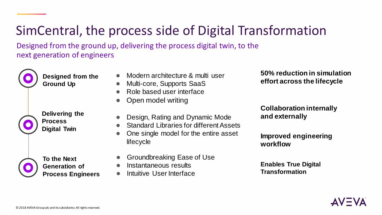
SimCentral, the process side of Digital Transformation
© 2018 AVEVA Group plc and its subsidiaries. All rights reserved.
Designed from the ground up, delivering the process digital twin, to the next generation of engineers
Delivering the
Process
Digital Twin
● Design, Rating and Dynamic Mode
● Standard Libraries for different Assets
● One single model for the entire asset
lifecycle
50% reduction in simulation
effort across the lifecycle
Collaboration internally
and externally
Enables True Digital
Transformation
Improved engineering
workflow
Designed from the
Ground Up
● Modern architecture & multi user
● Multi-core, Supports SaaS
● Role based user interface
● Open model writing
To the Next
Generation of
Process Engineers
● Groundbreaking Ease of Use
● Instantaneous results
● Intuitive User Interface

SimCentral Simulation Platform
© 2019 AVEVA Group plc and its subsidiaries. All rights reserved.
Designed from the ground up, delivering the process digital twin, to the next generation of engineers.
SimSci Thermodynamics
Use proven SimSci
thermodynamics and import data
using industry standards for high-
speed and accurate solutions with
all major thermo methods.
Library Approach
Provides model libraries for
process utilities (steam, cooling
water), flares, as well as
process simulation.
Open Modeling
Being able to see and modify the
underlying mathematical
equations enables the process
engineer to include advanced
customization
Steady-State & Dynamics
Seamless switching between
steady state, rating, and
dynamic modes drives
collaboration across engineering
domains and model reuse through
the project lifecycle.
Equation-Oriented Solver
The robust equation-oriented
solver using state-of-the-art
numerics allows for efficient
calculation even when there are
lots of recycles.
Ease of Use
The highly interactive,
continuously solved process
simulator with Undo enables
rapid exploration of the problem.
New Applications
The open platform extendable
architecture allows the expansion
of process simulation into other
industries such as batch, power,
and more.
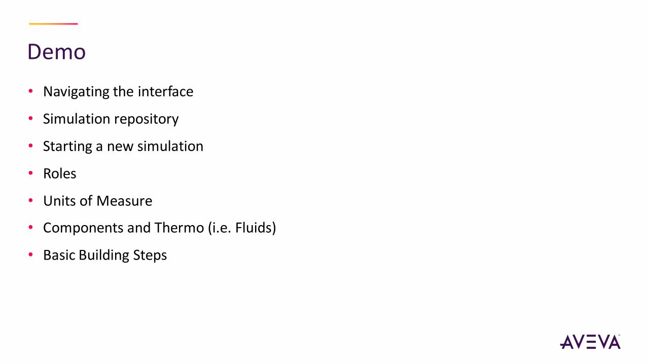
Demo
• Navigating the interface
• Simulation repository
• Starting a new simulation
• Roles
• Units of Measure
• Components and Thermo (i.e. Fluids)
• Basic Building Steps

Canvas Badges
• On the Canvas
• Input Required
• Warning
• Not Solved
• To view a description of the issue, hover over
the badge
• To suppress Input Required Badges:
• Under Edit/View
• Uncheck Required Badges
Note: Hover over badge for a description of the issue.
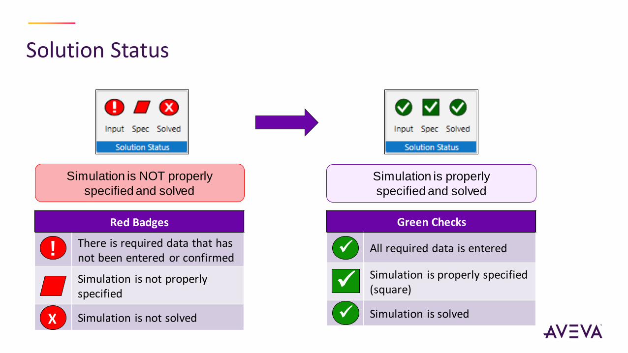
Solution Status
Red Badges
There is required data that has not been entered or confirmed
Simulation is not properly specified
Simulation is not solved
Green Checks
All required data is entered
Simulation is properly specified (square)
Simulation is solved
! ✓
✓
Simulation is NOT properly
specified and solved
Simulation is properly
specified and solved
X ✓

SimCentral Work Process
• Build and solve as you go:
• Connect one Model at a time
• Enter required data
• Keep your simulation properly specified (Spec) and Solved
• Don’t make changes to the simulation unless these 2 conditions are met
• If you make a mistake, use Undo to return the simulation to its previous state
• Take frequent Snapshots of solved simulations (covered in the next section)
• Do not continue to build the flowsheet, if the simulation is not “Square”
(properly specified) and Solved

Demo
• Mini and full property inspectors
• Simulation level full property inspector and changed specifications
• Swapping specifications and recommended workflow
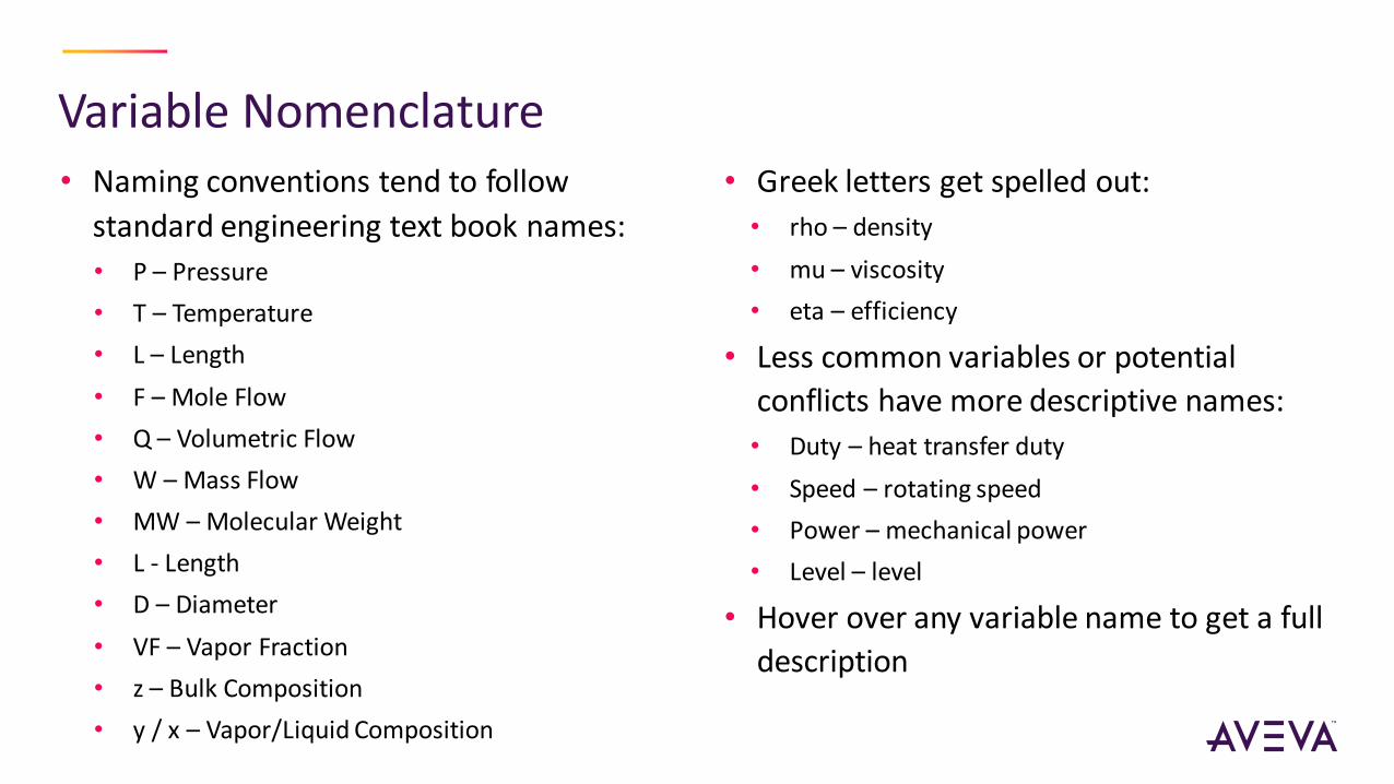
Variable Nomenclature • Naming conventions tend to follow
standard engineering text book names:
• P – Pressure
• T – Temperature
• L – Length
• F – Mole Flow
• Q – Volumetric Flow
• W – Mass Flow
• MW – Molecular Weight
• L - Length
• D – Diameter
• VF – Vapor Fraction
• z – Bulk Composition
• y / x – Vapor/Liquid Composition
• Greek letters get spelled out:
• rho – density
• mu – viscosity
• eta – efficiency
• Less common variables or potential
conflicts have more descriptive names:
• Duty – heat transfer duty
• Speed – rotating speed
• Power – mechanical power
• Level – level
• Hover over any variable name to get a full
description
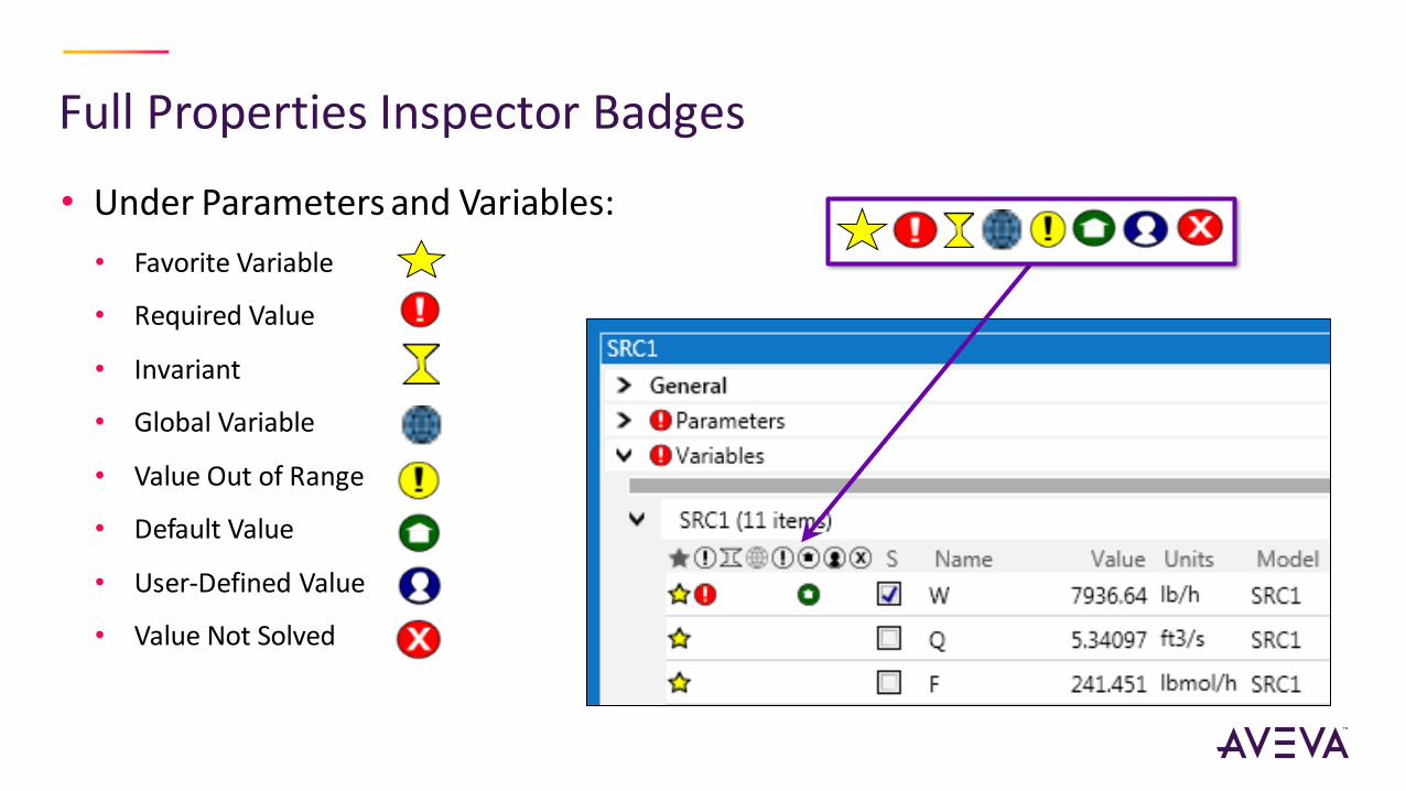
Full Properties Inspector Badges
• Under Parameters and Variables:
• Favorite Variable
• Required Value
• Invariant
• Global Variable
• Value Out of Range
• Default Value
• User-Defined Value
• Value Not Solved
Demo
• Snapshots and snapshot manager
• How to handle mistakes
• Running and messaging
• Specific output capabilities, such as variable references, tables, profiles, and trends
• Excel reporting
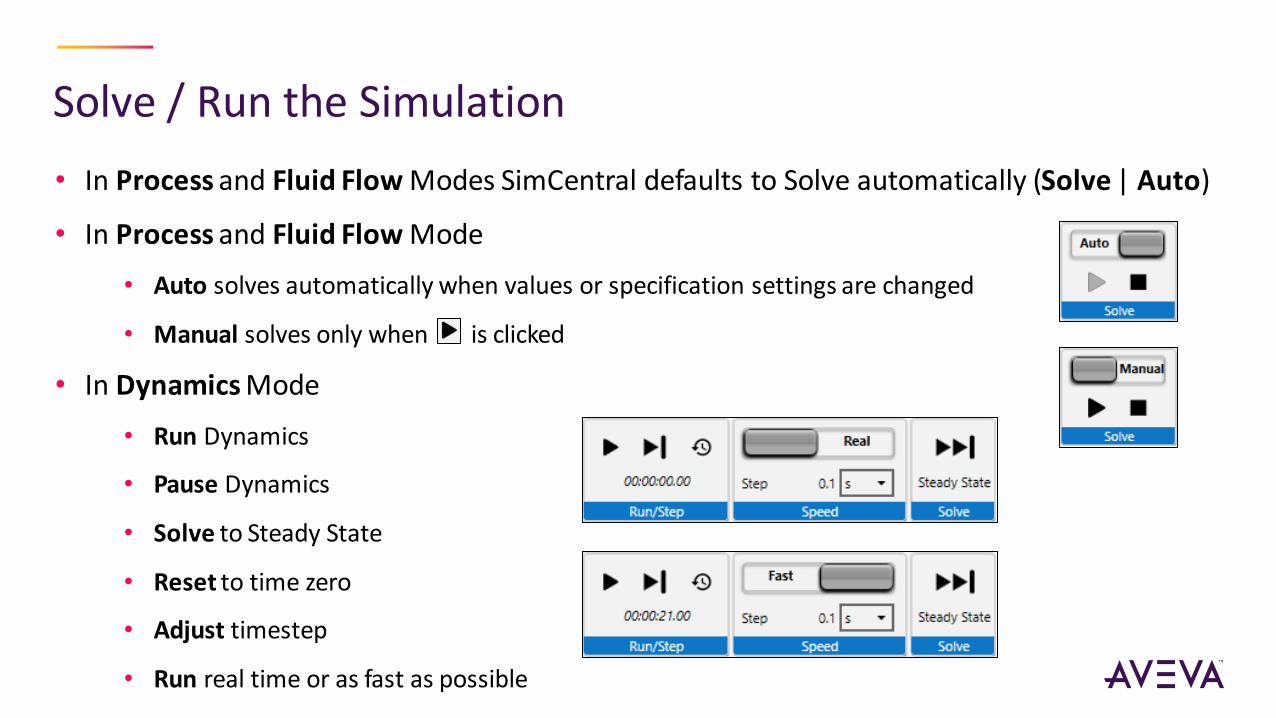
Solve / Run the Simulation
• In Process and Fluid Flow Modes SimCentral defaults to Solve automatically (Solve | Auto)
• In Process and Fluid Flow Mode
• Auto solves automatically when values or specification settings are changed
• Manual solves only when is clicked
• In Dynamics Mode
• Run Dynamics
• Pause Dynamics
• Solve to Steady State
• Reset to time zero
• Adjust timestep
• Run real time or as fast as possible

Messages Window
• Turn on from Edit/View |
Show | check Messages
box
• One window which
displays all messages for
the simulation (includes
input messages, warnings
and error messages)
• Double click model name
to locate on Canvas
• Messages can be
copied/pasted
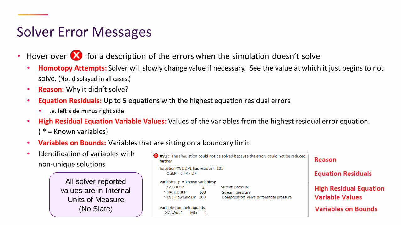
Solver Error Messages
• Hover over for a description of the errors when the simulation doesn’t solve
• Homotopy Attempts: Solver will slowly change value if necessary. See the value at which it just begins to not
solve. (Not displayed in all cases.)
• Reason: Why it didn’t solve?
• Equation Residuals: Up to 5 equations with the highest equation residual errors
• i.e. left side minus right side
• High Residual Equation Variable Values: Values of the variables from the highest residual error equation.
( * = Known variables)
• Variables on Bounds: Variables that are sitting on a boundary limit
• Identification of variables with
non-unique solutions
All solver reported
values are in Internal
Units of Measure
(No Slate)

MS-Excel Reports
• Create custom reports using MS-Excel
• Currently the only way of creating external reports
• No need to know any coding
• Uses MS-Excel function calls and basic equation writing similar to writing formulas in MS-Excel
• The MS-Excel Add-In must be installed during the installation of SimCentral to use this
feature
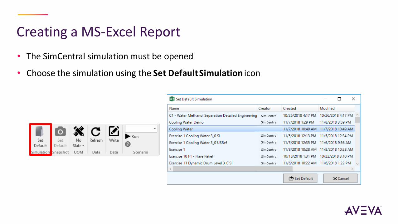
Creating a MS-Excel Report
• The SimCentral simulation must be opened
• Choose the simulation using the Set Default Simulation icon
SimCentral
SimCentral
SimCentral
SimCentral
SimCentral
SimCentral
SimCentral
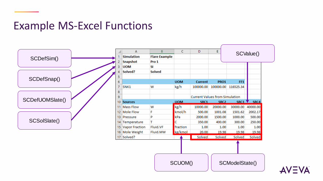
Example MS-Excel Functions
SCDefSim()
SCDefUOMSlate()
SCDefSnap()
SCSolSlate()
SCModelState()SCUOM()
SCValue()

Simulation ModesPrimary Secondary Attributes
Process“Flow-Driven Steady State”
For creating heat and material balances and sizing equipment
Best to add new equipment Models here
For setting up initial conditions for Fluid Flow
Fluid Flow“Pressure-Driven Steady State”
For solving pressure networks and rating process equipment
For creating bump-less initial Steady State condition for Dynamics
Dynamics“Pressure-Driven Dynamics”
For determining transient response and evaluating controls
• Flows and Pressure Profile are defined
• Pipes specifications include pressure
drop or velocity
• Mixers use the smaller of the inlet
pressures
• Pressures defined at boundaries
• Actual pipe diameters are used
• Mixers set all streams to the same
pressure
• Usually same as fluid flow specification
• Differential equations
• Accumulation

Moving between Modes
• Most values stay the same during Mode changes
…unless there are Mode specific equation changes
• Same values seems natural when going forward
• e.g. from Process to Fluid Flow
• But if the equations change, there could be changes in variable values
• e.g. From required pipe diameter to actual pipe diameter
• e.g. Remove mixer pressure slack
• Be aware that going “back” will retain calculated values
• e.g. from Fluid Flow to Process
• On the Ribbon, under Snapshots, select Revert, if your last solution is desired
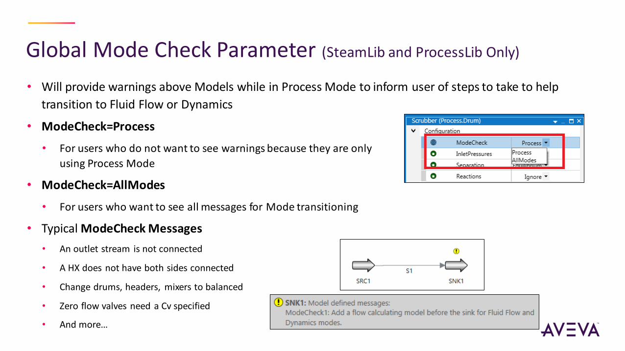
Global Mode Check Parameter (SteamLib and ProcessLib Only)
• Will provide warnings above Models while in Process Mode to inform user of steps to take to help
transition to Fluid Flow or Dynamics
• ModeCheck=Process
• For users who do not want to see warnings because they are only
using Process Mode
• ModeCheck=AllModes
• For users who want to see all messages for Mode transitioning
• Typical ModeCheck Messages
• An outlet stream is not connected
• A HX does not have both sides connected
• Change drums, headers, mixers to balanced
• Zero flow valves need a Cv specified
• And more…

Demo
• Mode Transitioning
• Global Mode Check Parameter

For Fluid Flow and Dynamics Mode Transitions
• Required:
• Sinks
• Recommended:
• Valves or Pipes between Sources and Headers
• Valves or Pipes between Headers
• Both sides of HX modeled
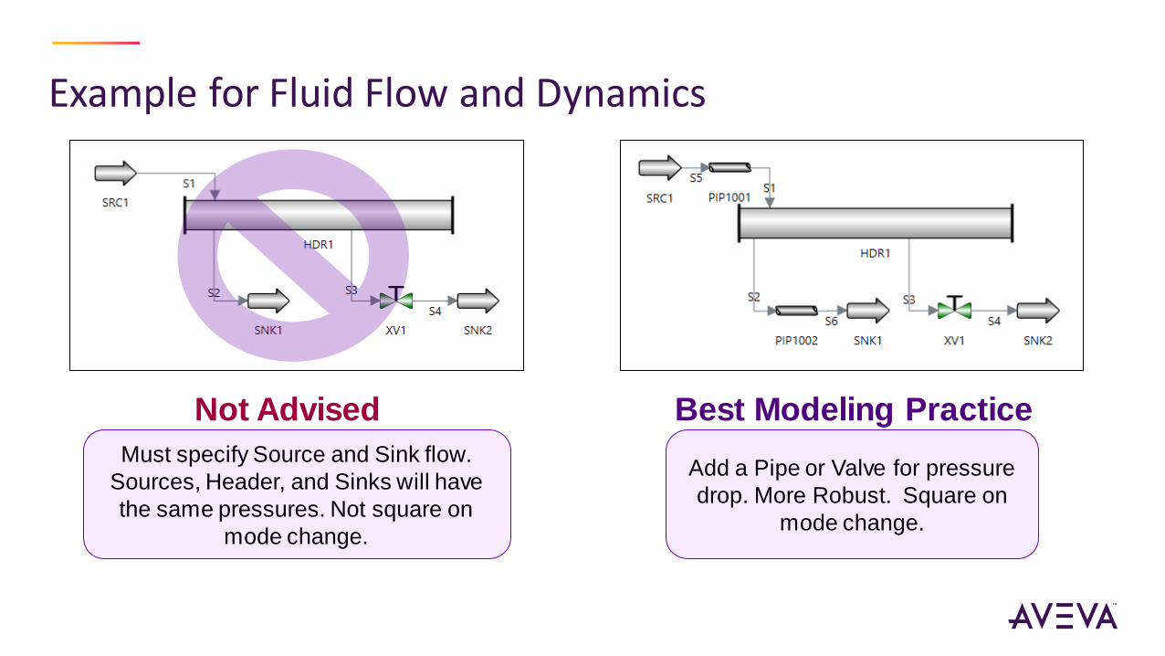
Example for Fluid Flow and Dynamics
Must specify Source and Sink flow.
Sources, Header, and Sinks will have
the same pressures. Not square on
mode change.
Add a Pipe or Valve for pressure
drop. More Robust. Square on
mode change.
Not Advised Best Modeling Practice
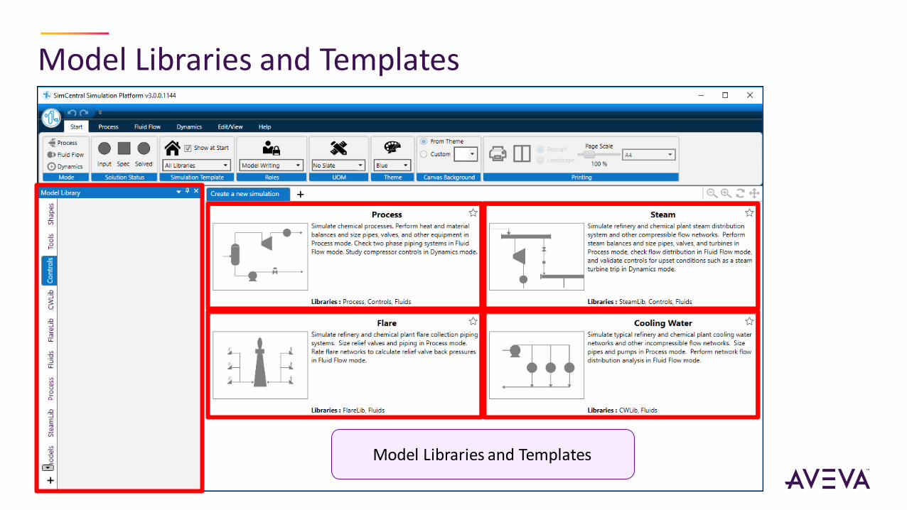
Model Libraries and Templates
Model Libraries and Templates
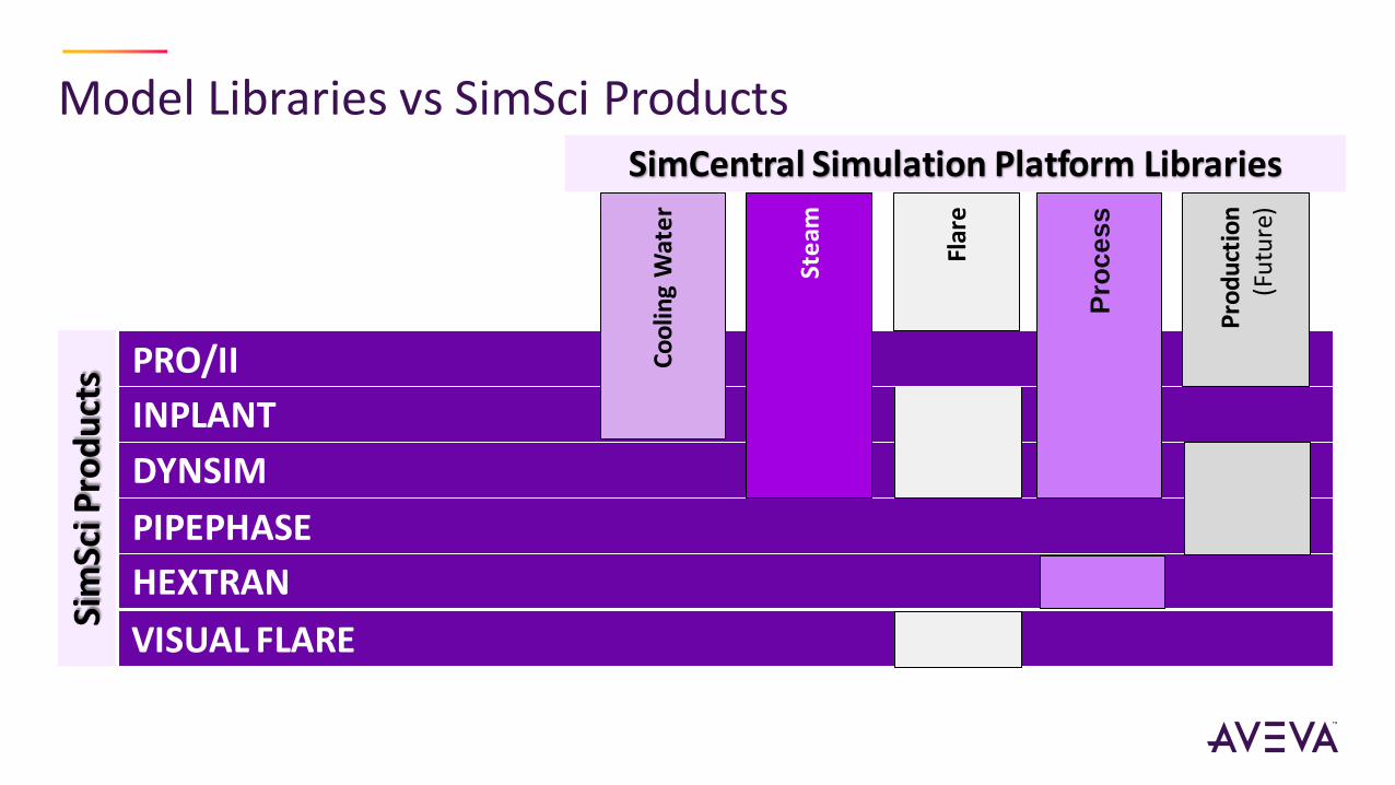
Model Libraries vs SimSci ProductsSi
mSc
i Pro
du
cts
PIPEPHASE
HEXTRAN
INPLANT
VISUAL FLARE
DYNSIM
PRO/II Co
olin
g W
ate
r
Ste
am
Pro
ce
ss
Pro
du
ctio
n
(Fu
ture
)
SimCentral Simulation Platform Libraries
Flar
e
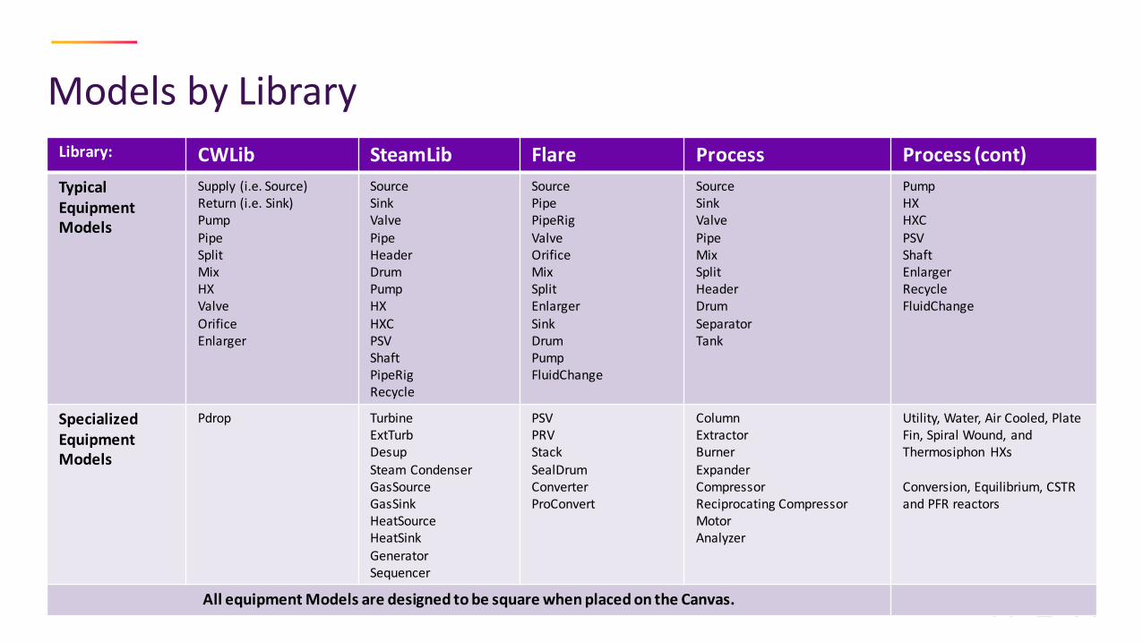
Models by LibraryLibrary: CWLib SteamLib Flare Process Process (cont)
TypicalEquipmentModels
Supply (i.e. Source)Return (i.e. Sink)PumpPipeSplitMixHXValveOrificeEnlarger
SourceSinkValvePipeHeaderDrumPumpHXHXCPSVShaftPipeRigRecycle
SourcePipePipeRigValveOrificeMixSplitEnlargerSinkDrumPumpFluidChange
SourceSinkValvePipeMixSplitHeaderDrumSeparatorTank
PumpHXHXCPSVShaftEnlargerRecycleFluidChange
Specialized EquipmentModels
Pdrop TurbineExtTurbDesupSteam CondenserGasSourceGasSinkHeatSourceHeatSinkGeneratorSequencer
PSVPRVStackSealDrumConverterProConvert
ColumnExtractorBurnerExpanderCompressorReciprocating CompressorMotorAnalyzer
Utility, Water, Air Cooled, Plate Fin, Spiral Wound, and Thermosiphon HXs
Conversion, Equilibrium, CSTR and PFR reactors
All equipment Models are designed to be square when placed on the Canvas.
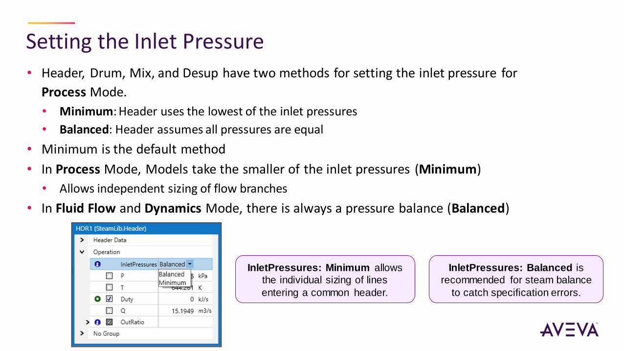
Setting the Inlet Pressure• Header, Drum, Mix, and Desup have two methods for setting the inlet pressure for
Process Mode.
• Minimum: Header uses the lowest of the inlet pressures
• Balanced: Header assumes all pressures are equal
• Minimum is the default method
• In Process Mode, Models take the smaller of the inlet pressures (Minimum)
• Allows independent sizing of flow branches
• In Fluid Flow and Dynamics Mode, there is always a pressure balance (Balanced)
InletPressures: Minimum allows
the individual sizing of lines
entering a common header.
InletPressures: Balanced is
recommended for steam balance
to catch specification errors.
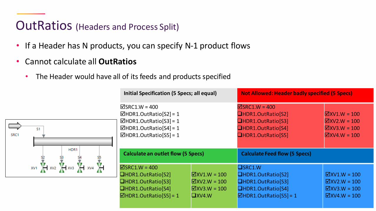
OutRatios (Headers and Process Split)
• If a Header has N products, you can specify N-1 product flows
• Cannot calculate all OutRatios
• The Header would have all of its feeds and products specified
Initial Specification (5 Specs; all equal)
SRC1.W = 400HDR1.OutRatio[S2] = 1HDR1.OutRatio[S3] = 1HDR1.OutRatio[S4] = 1HDR1.OutRatio[S5] = 1
Not Allowed: Header badly specified (5 Specs)
SRC1.W = 400❑HDR1.OutRatio[S2]❑HDR1.OutRatio[S3]❑HDR1.OutRatio[S4]❑HDR1.OutRatio[S5]
XV1.W = 100XV2.W = 100XV3.W = 100XV4.W = 100
Calculate an outlet flow (5 Specs) Calculate Feed flow (5 Specs)
SRC1.W = 400❑HDR1.OutRatio[S2]❑HDR1.OutRatio[S3]❑HDR1.OutRatio[S4]HDR1.OutRatio[S5] = 1
XV1.W = 100XV2.W = 100XV3.W = 100❑XV4.W
❑SRC1.W❑HDR1.OutRatio[S2]❑HDR1.OutRatio[S3]❑HDR1.OutRatio[S4]HDR1.OutRatio[S5] = 1
XV1.W = 100XV2.W = 100XV3.W = 100XV4.W = 100
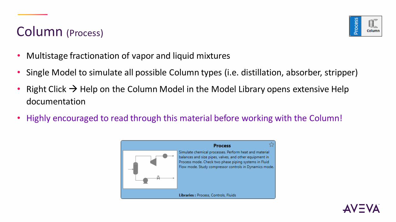
Column (Process)
• Multistage fractionation of vapor and liquid mixtures
• Single Model to simulate all possible Column types (i.e. distillation, absorber, stripper)
• Right Click → Help on the Column Model in the Model Library opens extensive Help
documentation
• Highly encouraged to read through this material before working with the Column!

Typical Workflow for Column Building
• Preparing your simulation for the addition of the Column
• Achieve a squared/solved state
• Ensure feed information is accurate
• Step 1: Building the base Column Model as a starting point
• Step 2: Achieve initial conceptual design solution in Process Mode
• Step 3: Achieve extended design for detailed engineering in Process Mode
• Step 4: Switching to Fluid Flow Mode for flow distribution analysis
• Step 5: Switching to Dynamics Mode for transient performance studies

Step 1: Starting Point
• Initial State:
• Square
• Defaults to 3 Stages
• Feed defaults to Stage 1
• Product streams not required
• Solved to a “no contact” solution
• No condenser
• No reboiler
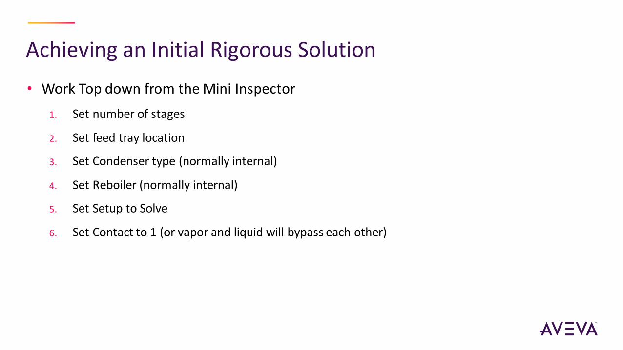
Achieving an Initial Rigorous Solution
• Work Top down from the Mini Inspector
1. Set number of stages
2. Set feed tray location
3. Set Condenser type (normally internal)
4. Set Reboiler (normally internal)
5. Set Setup to Solve
6. Set Contact to 1 (or vapor and liquid will bypass each other)

Step 2: Initial Configuration (i.e. Conceptual Design)
• Edit configuration:
• Number of stages, feed location, condenser and reboiler configuration
• Column model can represent any and all types of Columns (depends on the configuration of the
Column)
• Specify internal or external specifications
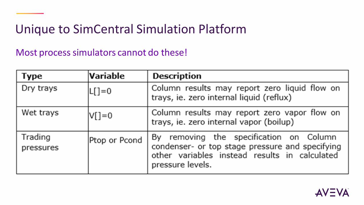
Unique to SimCentral Simulation Platform
Most process simulators cannot do these!
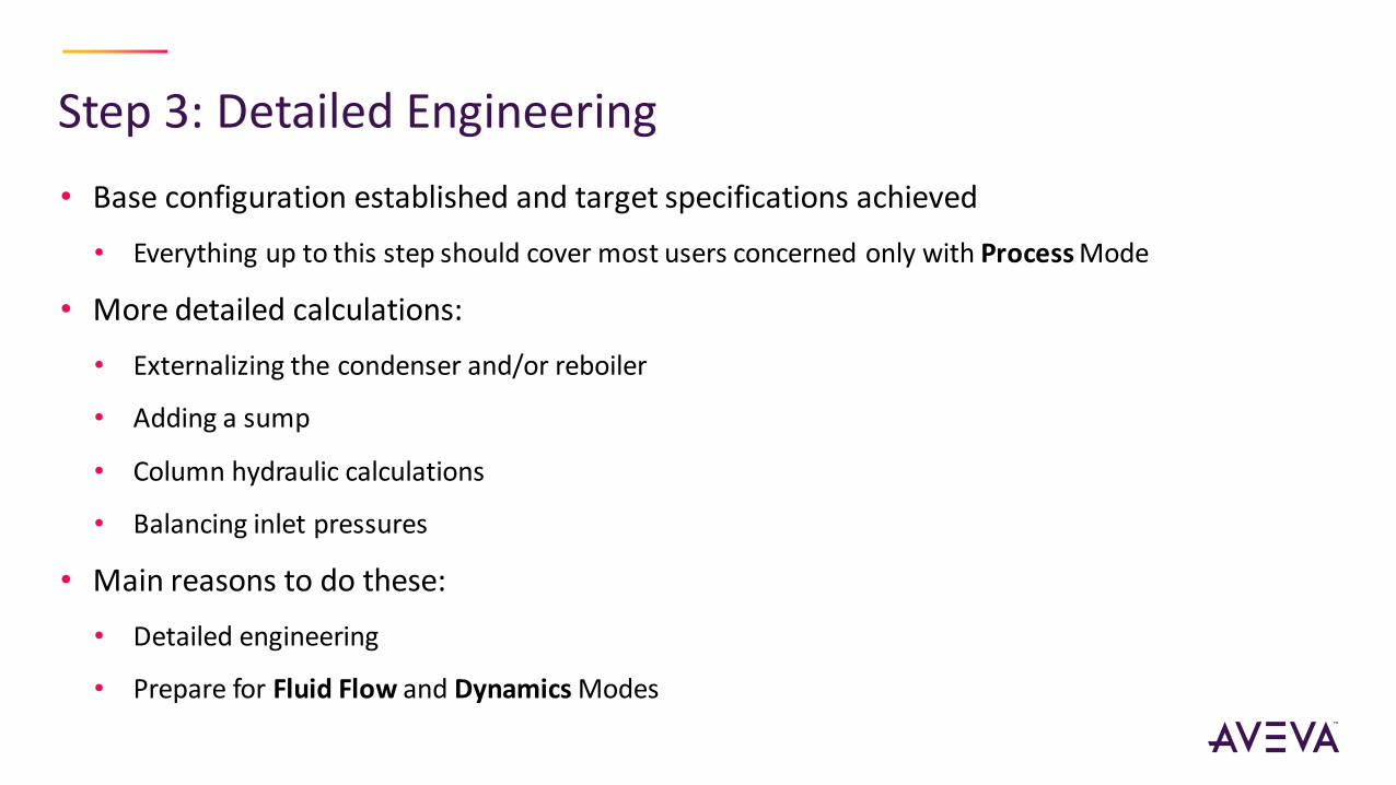
Step 3: Detailed Engineering
• Base configuration established and target specifications achieved
• Everything up to this step should cover most users concerned only with Process Mode
• More detailed calculations:
• Externalizing the condenser and/or reboiler
• Adding a sump
• Column hydraulic calculations
• Balancing inlet pressures
• Main reasons to do these:
• Detailed engineering
• Prepare for Fluid Flow and Dynamics Modes

Condenser and Reboiler Drum dimensions
Condenser and Reboiler Level
Reboiler with Sump Option
Uses built in or external controls
Before we continue…All Mode Column
• Go directly to Fluid Flow and
Dynamics without having to
“Externalize” the overhead and
reboiler sections.
• Includes options for:
• Built in receiver and reboiler dynamics
• Kettle Reboiler or Reboiler with Sump
• 3 automated, internal or external control
schemes

Demo
• Show/Hide Model Libraries
• Column Building
• Model Help
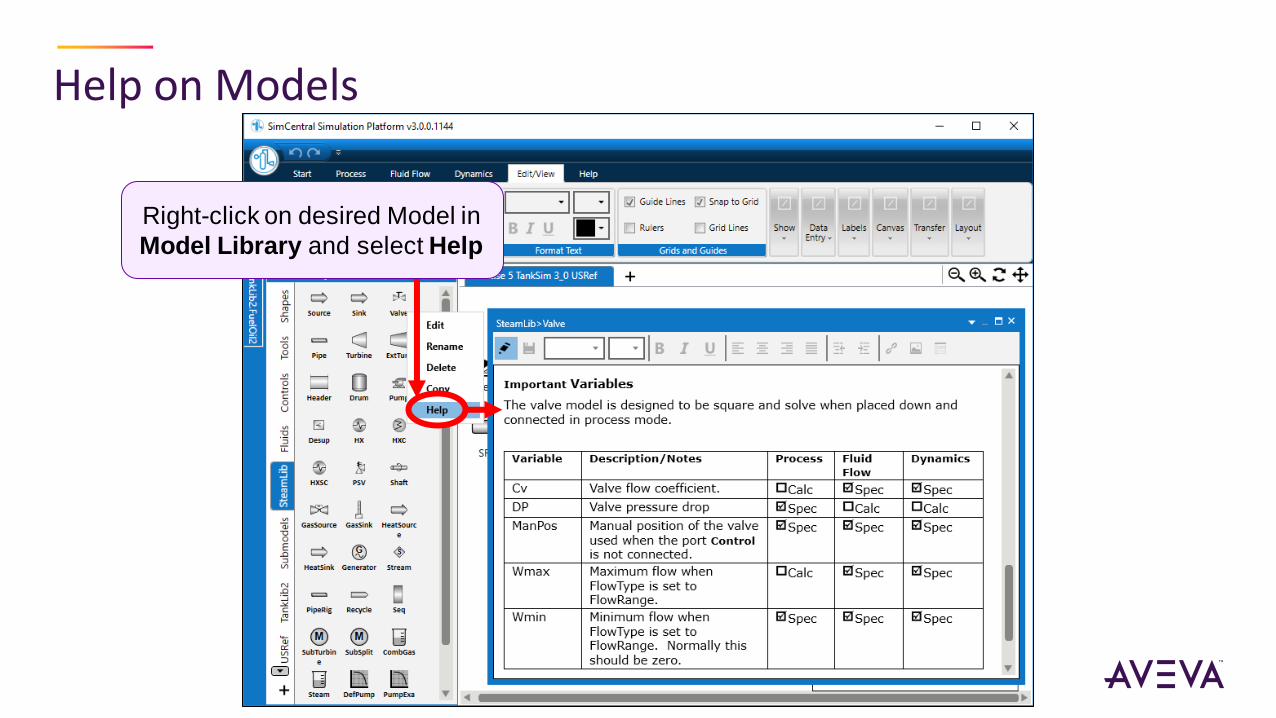
Help on Models
Right-click on desired Model in
Model Library and select Help

Glossary

Video Tutorials
Finished Simulation Demos

Demos of Finished Simulations
• Cooling Water Network (U4 - Cooling Water Network)
• Steam Balance (U7 - Refinery Steam Balance with Optimization)
• Flare Network (F4 - Two Phase Flare Relief)
• Cumene Production (CC2 - Cumene Production)

Exercises

Process Library
ExercisePRO-1A Chiller Plant - Process Library Getting Started
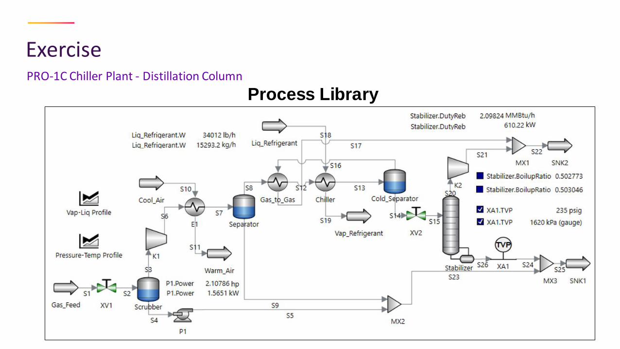
Process Library
ExercisePRO-1C Chiller Plant - Distillation Column
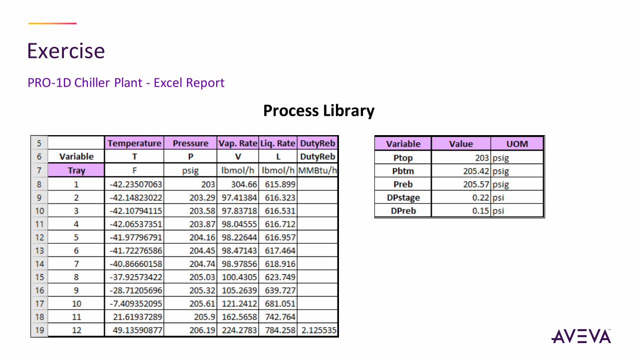
ExercisePRO-1D Chiller Plant - Excel Report
Process Library
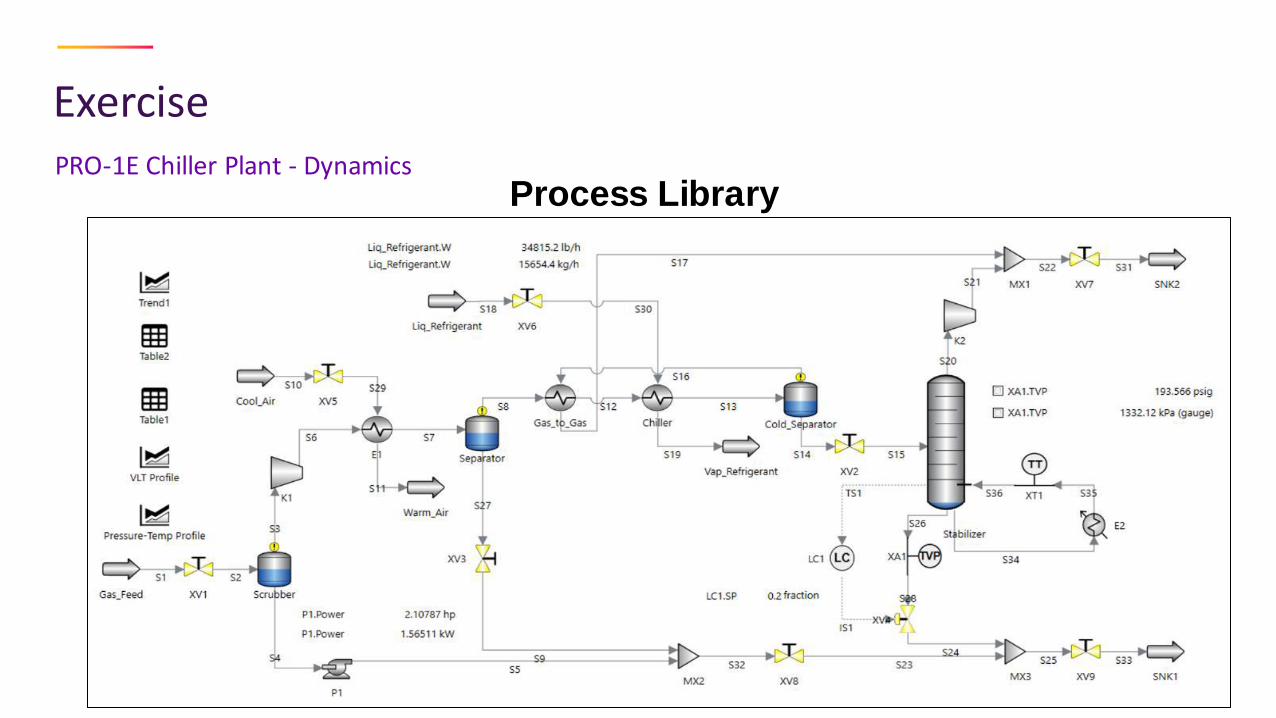
ExercisePRO-1E Chiller Plant - Dynamics
Process Library

Questions & Discussion
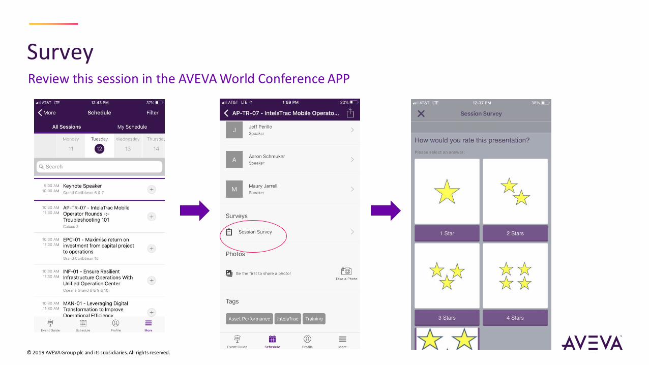
Survey
© 2019 AVEVA Group plc and its subsidiaries. All rights reserved.
Review this session in the AVEVA World Conference APP
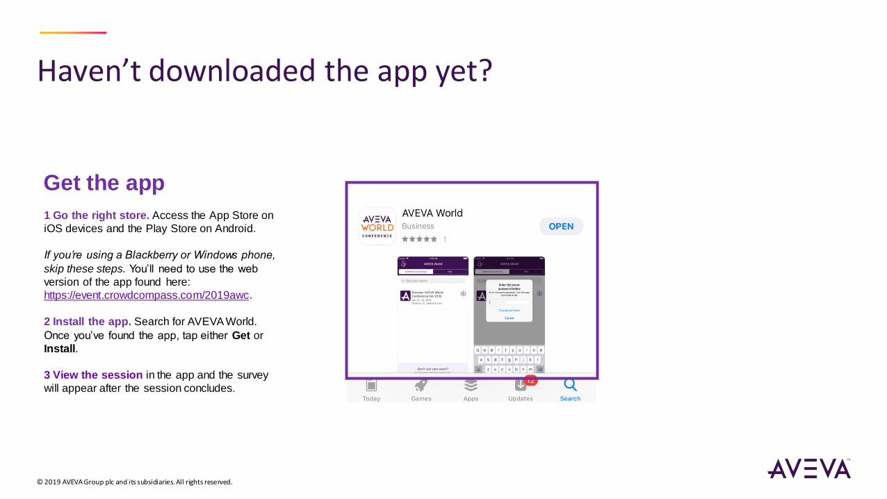
Haven’t downloaded the app yet?
© 2019 AVEVA Group plc and its subsidiaries. All rights reserved.
Get the app
1 Go the right store. Access the App Store on
iOS devices and the Play Store on Android.
If you’re using a Blackberry or Windows phone,
skip these steps. You’ll need to use the web
version of the app found here:
https://event.crowdcompass.com/2019awc.
2 Install the app. Search for AVEVA World.
Once you’ve found the app, tap either Get or
Install.
3 View the session in the app and the survey
will appear after the session concludes.

linkedin.com/company/aveva
@avevagroup
ABOUT AVEVA
AVEVA is a global leader in engineering and industrial software driving digital transformation across the entire asset and operational l ife cycle of capital -intensive industries.
The company’s engineering, planning and operations, asset performance, and monitoring and control solutions deliver proven results to over 16,000 customers across the globe. Its customers are supported by the largest industrial software ecosystem, including 4,200 partners and 5,700 certified developers. AVEVA is headquartered in Cambridge, UK, with over 4,400 employees at 80 locations in over 40 countries.
aveva.com
© 2019 AVEVA Group plc and its subsidiaries. All rights reserved.