© 5/12 kwikee #1422279 rev. 0i electric...
TRANSCRIPT

Single Steps Double Steps Triple Steps Van Steps
Owner'sManual#888
© 5/12 Kwikee #1422279 Rev. 0I
Electric Steps
Equipped with a Permanent Magnet Motor(For steps with Control Units 909510000 and steps without Control Units)
2 Identification Information
3 Introduction 4 Operation
5-6 Maintenance: • Lubrication • Cam Stop Adjustment 7 General Service Notes 7-11 Troubleshooting and Testing Procedures
12 Warranty
Table of ContentsSafely Supports up to
750 lbs
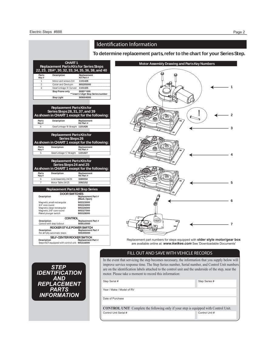
Identi�cation Information
Electric Steps #888 Page 2
Motor Assembly Drawing and Parts Key NumbersCHART 1Replacement Parts Kits for Series Steps
22, 23, 28A*, 30, 32, 33, 34, 35, 36, 38, and 40Parts Description ReplacementKey # Kit Part #________________________________________________________________
1 Motor and screws 214 1101428________________________________________________________________2 Cotter and Clevis pin 905205000________________________________________________________________3 Gear/Linkage 'A' Curved 1101425________________________________________________________________
Step Frame only 9080**000 **insert 2 digit Step Series number________________________________________________________________Step Light 909004000
Replacement Parts Kits forSeries Steps 28, 31, 37, and 39
As shown in CHART 1 except for the following:
Parts Description ReplacementKey # Kit Part #________________________________________________________________
4 Gear/Linkage 'B' Straight 1101426
Replacement Parts Kits forSeries Steps 26
As shown in CHART 1 except for the following:Parts Description ReplacementKey # Kit Part #________________________________________________________________
5 Gear/Linkage 'C' Straight 1101427
Replacement Parts Kits forSeries Steps 24 and 25
As shown in CHART 1 except for the following:Parts Description ReplacementKey # Kit Part #________________________________________________________________
6 Link/Assembly 24/25 3380050________________________________________________________________7 Motor Table 24/25 3392152
Replacement Parts All Step SeriesDOOR SWITCHES
Description Replacement Part #(Black, Open)
Magnetic, small rectangular 9053230003/4" core round 905324000Magnetic, large rectangular 905326000Magnetic, 3/8" core round 905327000Plated plunger switch 905328000
ROCKER STYLE POWER SWITCHDescription Replacement Part #For all fully automatic steps 905305000
SELF-CENTER ROCKER SWTICHDescription Replacement Part #Steps NOT equipped with control unit 905316000
CONTROLDescription Replacement Part #Control with step lockout 909510000
Replacement part numbers for steps equipped with older style motor/gear boxare available online at: www.kwikee.com See 'Downloadable Documents'
STEP IDENTIFICATION
ANDREPLACEMENT
PARTSINFORMATION
FILL OUT AND SAVE WITH VEHICLE RECORDSIn the event that servicing the step becomes necessary, the information that you supply below will improve service response time. The Step Series number, Serial number, and Control Unit numbers are on the identification labels attached to the control unit and the underside of the step, near themotor. Please take a moment to record this information:
CONTROL UNIT Complete the following only if your step is equipped with Control Unit.
Step Serial #
Year / Make / Model of RV
Date of Purchase
Step Series #
Control Unit Serial # Control Unit #
To determine replacement parts, refer to the chart for your Series Step.
1
2
3
4
5
6
7
Electric Steps #888 Page 3
IntroductionSTEPS WITH CONTROL UNIT
This manual has been provided to assist you with the identification, operation, maintenance, and troubleshooting of the Kwikee electric step equipped for use with a step lockout switch, control unit and permanent magnet motor. This manual does not apply and should not be used as a reference to previous versions of a Kwikee electric step.
The control unit is essentially a current sensor as well as a switching device. When the motor assembly moves the step tread to its extended position, or stops moving because of an obstruction such as a curb or the binding of a damaged or bent step frame, the motor draws a larger amount of current. The control unit ‘senses’ the larger current draw and shuts off the power to the motor.
All control units are equipped with an ignition override system. This system is designed so that the vehicle will not be driven with the step in the extended position. When the step is locked in the extended position, the door closed, and the ignition is turned on, the ignition override system will engage and the step will automatically retract. Note: Refer to vehicle OEM owner’s manual (or OEM Requirements) which will provide switch position of “on” or “off” for the step lock position.
The ‘Auto Extend’ feature is another safety feature designed to extend the step when the door is opened for the first time after the vehicle ignition is turned off, regardless of the position of the step switch.
Some van steps use door-switch-only operation. When the door is opened the step extends and the step retracts when the door is closed.
STEPS WITHOUT CONTROL UNIT
This manual has been provided to assist you with the identification, operation, maintenance, and troubleshooting of the Kwikee electric step equipped with a self-centering rocker switch. This manual does not apply and should not be used as a reference to previous versions of a Kwikee electric step.
NOTE: Follow the instructions in this manual carefully. Failure to do so may result in damage to the step control, the motor and/or the vehicle wiring. Such damage may also result in voiding the warranty.
• Updated new Control Units are equipped with an ignition override system designed to prevent the vehicle from being driven with the step in the extended position. When the step is locked in the extended position, the door is closed, and the ignition is turned on, the ignition override system will engage and the step will automatically retract.
Note: Refer to vehicle OEM owner’s manual (or OEM Requirements) which will provide the switch position of “on” or “off” for the step lock position. The step cannot be locked in the retracted position.
WARNING!Step control wiring is only to be used for step and step light (provided with the step) functions. Do not splice, cut or tap into any of the step wiring. Failure to heed this warning may result in voiding the warranty and/or failure of step control, which may result in loss of step function or fire in the step control. Refer any questions to the step manu-facturer.
CAUTION!Follow the instructions in this manual carefully. Failure to do so may result in damage to the step control, the motor and/or the vehicle wiring. Such damage may also result in voiding the warranty.
NOTICE!
CAUTION!Step safely supports up to 750 lbs. DO NOT OVERLOAD THE STEP ASSEMBLY.
Electric Steps #888 Page 4
OperationSTEP WITH CONTROL UNIT--(Normal Operation/Automatic Mode)
1. After the installation is complete and with the entrance door open, place the step switch in the position indicated in the OEM Owner’s Manual (or OEM Requirements) for the step to extend when the door is opened and retract when the door is closed (step follows the door).
2. Close the door. The step should retract and lock in the ‘up’ position.
3. Open the door. The step should extend and lock in the ‘down’ position with the understep light illuminated. NOTE: The understep light operation is as follows: ● The light is ‘on’ when the step is extended ● The light is ‘off’ when the step is retracted ● In the event the coach door / screen door is left open, the light will turn ‘off’ after 5 minutes ● The understep light is not available on all step models STEP WITH CONTROL UNIT--(Step Lock Function/Stationary Extended Mode.)
1. If your step is equipped with a step switch, and you would like the step to remain in the extended position while the door is opned and closed, place the step switch in the position indicated in the OEM Owner’s Manual (or OEM Requirements). The step should remain in the extended position with the understep light ‘off’ when the door is closed.
2. With the step switch in the appropriate step lock position, the step extended, and the entrance door closed, turn the vehicle ignition on. The ignition override system will go into effect and the step will automatically retract. NOTE: If the yellow wire from the four-way connector is not connected to an ignition power source, the ignition safety system will be inoperative and the step will remain in the extended position. In this case, the step lock switch must be placed in the Automatic Mode position for the step to retract.
3. Turn the vehicle ignition off and open the door. The step will extend and lock in the ‘down’ position. This is the ‘Auto Extend’ feature. When the vehicle ignition is turned on, the step will always activate with the door movement, regardless of the step switch position. NOTE: If the yellow wire from the four-way connector is not connected to an ignition power source, the ignition will not cause the step to retract if the step lock switch is placed in the Automatic Mode position, regardless of the door position.
STEPS WITHOUT CONTROL UNIT
1. To extend the step, push and hold the bottom half of the rocker switch. Make sure the step is completely extended and locked in position before releasing the switch.
2. Push and hold the top of the rocker switch to retract the step. Be sure the step is completely retracted and locked in position before releasing the switch NOTE: The extend/retract function will be reversed if the red and yellow terminal connections are reversed or the step is equipped with a reverse-driven motor assembly (such as on the 37 and 42 series steps).
CAUTION!If the vehicle is driven with the step in the extended position, there is the possi-bility of causing major damage to both the step and the vehicle.
Stepping on a partially extended step can cause damage to the step frame. Wait until the step is fully extended before stepping on it.
Do not hold the switch in for longer than it takes to either extend or retract the step or damage to the motor will result.
CAUTION!
CAUTION!
CAUTION!Always be sure that the step is fully retracted before traveling. If the step is left extended and strikes an obstruction while the vehicle is moving, major damage to both the step and the vehicle could result.
CAUTION!Step safely supports up to 750 lbs. DO NOT OVERLOAD THE STEP ASSEMBLY.
Electric Steps #888 Page 5
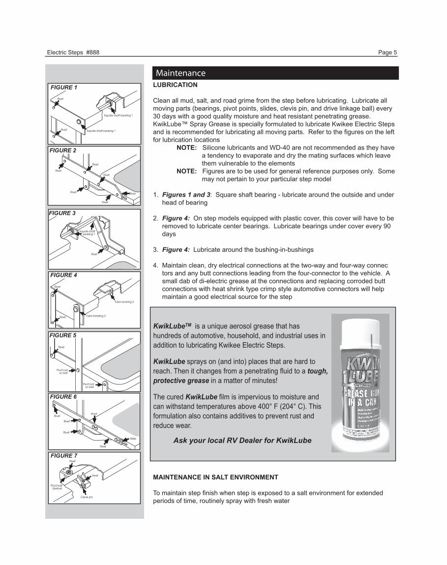
MaintenanceFIGURE 1
FIGURE 2
FIGURE 3
FIGURE 4
FIGURE 5
FIGURE 6
FIGURE 7
LUBRICATION
Clean all mud, salt, and road grime from the step before lubricating. Lubricate all moving parts (bearings, pivot points, slides, clevis pin, and drive linkage ball) every 30 days with a good quality moisture and heat resistant penetrating grease. KwikLube™ Spray Grease is specially formulated to lubricate Kwikee Electric Steps and is recommended for lubricating all moving parts. Refer to the figures on the left for lubrication locations NOTE: Silicone lubricants and WD-40 are not recommended as they have a tendency to evaporate and dry the mating surfaces which leave them vulnerable to the elements NOTE: Figures are to be used for general reference purposes only. Some may not pertain to your particular step model
1. Figures 1 and 3: Square shaft bearing - lubricate around the outside and under head of bearing
2. Figure 4: On step models equipped with plastic cover, this cover will have to be removed to lubricate center bearings. Lubricate bearings under cover every 90 days
3. Figure 4: Lubricate around the bushing-in-bushings
4. Maintain clean, dry electrical connections at the two-way and four-way connec tors and any butt connections leading from the four-connector to the vehicle. A small dab of di-electric grease at the connections and replacing corroded butt connections with heat shrink type crimp style automotive connectors will help maintain a good electrical source for the step
MAINTENANCE IN SALT ENVIRONMENT
To maintain step finish when step is exposed to a salt environment for extended periods of time, routinely spray with fresh water
KwikLubeTM is a unique aerosol grease that has hundreds of automotive, household, and industrial uses in addition to lubricating Kwikee Electric Steps.
KwikLube sprays on (and into) places that are hard to reach. Then it changes from a penetrating fluid to a tough,protective grease in a matter of minutes!
The cured KwikLube film is impervious to moisture and can withstand temperatures above 400° F (204° C). Thisformulation also contains additives to prevent rust and reduce wear.
Ask your local RV Dealer for KwikLube

Electric Steps #888 Page 6
FIGURE 9: Stop location and assembly
Push securelyagainst leg
Push securelyagainst leg
FIGURE 8: Gearbox and motor assembly.
Linkage
GearCase
These surfaces must be in contactfor the step to befully extended.
NylockNut
Tread side rail
Step top
Maintenance -Cont-
ADJUSTING THE CAM STOPS24, 25, 27, 28A*, 32, 34, 35, 36, 38, AND 40 Series Steps
Kwikee steps are fitted with adjustable cam stops on the step frame that help lock the step in the ‘out’ position, creating a firm stepping platform. The cam is adjusted at the factory but may fall out of adjustment and need to be tightened due to the rigors of shipping, installation, and normal use
The cam stops are located under the step top on the 28A*, 32, 36, and 38 Series Steps, and on the bottom tread side rail on the 24, 25, 27, and 40 Series Steps. There is one stop on each side of the step
1. Loosen the stops so they move freely and retract the step
2. Extend the step fully to its locked extended position (See FIG 8). Be sure that the motor assembly linkage rests against the gear case as illustrated in FIGURE 8. Repeat if needed until the motor assembly locks in the extended position
3. Push the stops against the leg and tighten securely (See FIG 9). Be sure that both stops are tightened and that they rest securely against the leg
4. Retract and fully extend the step. Check the motor assembly to be sure that it is locked all the way out, and that both stops are secure against the legs. Repeat the above procedures if needed to properly adjust the stops
5. Push on the front edge of the step tread. If the step seems loose, repeat the above procedures. The stops may not be properly adjusted so that they rest tightly against the leg
*28A is Step Part Number 902829XXX
WARNING!
When the cam stops are out of adjustment, the step may feel loose or ‘mushy’ when stepped on. If the cam stops are not properly adjusted the step may not extend fully to the locked-out position. Using a step with loose or out-of-adjustment cam stops may cause damage to the motor assembly and/or the drive linkage
CAUTION!When working under the step, be sure that the step cannot be activated and that nothing can get caught in the step mechanism
CAUTION!
Keep hands, feet, and clothing away from the step when extending and retract-ing. Failure to do so may result in personal injury.
Electric Steps #888 Page 7
General Service NotesIf the power wire to the step is disconnected from its source and reconnected, a spark is common. This is caused by the momentary charging of the control unit and does not necessarily indicate the system is staying on, which would cause a drain on the battery
To determine if a control unit is not shutting off, remove the four-way connector to the chassis and the two-way connector between the step motor and the contol unit. Place a voltmeter between the red and yellow motor wires at the two-way connector from the control unit. Reconnect the four-way Connector. Refer to OEM Owner’s Manual (or OEM Requirements) and place the step switch in the appropriate position for the step to remain in the extended position. If any voltage registers on the meter for more than 5 seconds, the control unit is not shutting off and may be defective. When doing this test, switch the voltmeter leads back and forth between the red and yellow motor wires to be sure no voltage registers
If any voltage registers for more than 5 seconds, disconnect the four-way connector to keep the step motor from overheating. If zero voltage is present, the control unit has shut off and is normal
If the step does not work or operates erratically (for example, extends part way and shuts off) the first item to check is the vehicle battery. Low supply voltage may cause erratic operation of the step. Poor ground connections may also cause erratic operation of the step. Check battery voltage and condition. A battery in good condition and properly charged will have a no load voltage or approx. 12.6 volts. Check the voltage at the battery and at the four-way connector at the control unit. Insure that all battery and step control unit connections are clean and secure. Recharge or replace the battery as necessary and retest the step for proper opera-tion
The step may also operate erratically if it is operating directly from a converter and the converter output is not adequate or properly filtered for clean DC voltage. The converter must be capable of producing a minimum of 30 amps for proper step operation
The step will not function if the ground to the control unit lost between the step control unit and the vehicle chassis (the long green ground wire) or between the vehicle battery and the ground (negative battery cable). Make sure the battery terminals and all wire connections are clean and tight. Verify that all wires meet the minimum requirements specified in Figures 10, 11, and 12 on page 9.
The step test procedures on page 8 are provided to troubleshoot and test all Kwikee automatic electric step functions. The procedures are designed to initially check the basic functions of the step separately from the RV wiring to determine whether or not the step is malfunctioning. The procedures test various components of the step until the source of the malfunction is located. Using the procedures will shorten and reduce the time spent troubleshooting.
Some portions of the test procedures require additional equipment. This equipment includes: - voltmeter - well charged 12V DC automotive battery - 4-way connector/pigtail (Part #909306000, available from Kwikee)
Read the entire procedure prior to testing.
Troubleshooting and Testing Procedures
These general service notes and the Step Test Procedures address the most common questions about Kwikee electric steps. Due to the number of variable conditions, you may experience symptoms other than those covered.

Electric Steps #888 Page 8
Troubleshooting and Testing Procedures, Cont
TESTING THE STEP
1. Inspect the step for visible damage that might restrict step operation2. Obtain a 4-way pigtail connector (part #909306000) from Kwikee3. Diconnect 4-way connector on underside of step and connect the step-half of the connector to the four-way connector pigtail. See Figures 10, 11, and 12 on Page 9.4. Set a fully charged 12V DC automotive battery beside the step. NOTE: Do not allow the battery terminals to come in contact with the step. Complete a ground for the step tests by connecting a 10 gauge wire from the negative (-) battery post to the green ground wire of the control unit5. To supply power, attach the red wire from the pigtail to the battery’s positive (+) post. The step will extend6. With the power and ground connections complete, all functions of the control unit can be checked at the four wires of the pigtail. The brown wire is the door switch, the white wire is the step lockout switch, and the yellow wire is the ignition override7. To retract the step, touch the brown wire to the negative (-) terminal8. To extend the step, remove the brown wire from the negative (-) terminal9. To test the ignition override feature, extend the step as in Step 8. With the step extended, connect the white wire to the positive (+) terminal and attach the brown wire to the negative (-) terminal. Next, touch the yellow wire to the battery’s positive (+) terminal. The step should retract. Remove the brown wire and the step should extend10.If any of the step functions do not work, the source of the malfunction is either in the control unit and/or the motor. Proceed to the “Testing the Motor” section on Page 10.
If all of the step functions do work, the malfunction is either in the door switch, step lockout switch, or the vehicle wiring. Proceed to “Testing the 4-way Connector” section on Page 10.
To test the “Auto Extend” feature, touch the brown wire to the negative (-) terminal to retract the step. While holding the brown wire to the negative (-) terminal, remove the yellow from the positive (+) terminal. Touch the white wire to the positive (+) terminal. The step will stay retracted.
Now, remove the brown wire and the step should extend.
Next touch the brown wire to the negative (-) terminal. The step should stay extended.
IMPORTANT INSTALLER NOTES:Be sure that all ground
connections are securely fastened with good
metal-to-metal contact. A good ground is required for
proper step operation
VAN STEPS
If the van step is equipped with a splash cover, remove the cover to access motor assembly and control unit. If step is locked in retracted (up) position and the plastic cover can not be removed, disassemble the step tread to access the plastic cover.
To disassemble the tread, remove the (8) 1/4-20 x 1” long hex head bolts in tread side rails (connects tread and sliding blocks to side rail). This allows the tread to drop out of the way and the plastic cover to be accessible.
Reassemble the tread after removing the cover. Reinstall the cover after testing procedures and any necessary repairs are complete. Fully extend the step to reinstall the cover. Be sure that the four-way connector exits the notch in the plastic cover when reassembling.
WARNING!12 volt automotive batteries contain sulfuric acid which can cause severe burns. Avoid contact with the skin, eyes, and clothing. 12 volt automotive batteries produce hydrogen gas which is explo-sive; keep cigarettes, open flames, and sparks away from the battery at all times
WARNING!Keep fingers, arms, and legs clear of step mechanism while performing these test. Failure to do so may result in personal injury
CAUTION!Do not allow the battery terminals to come in contact with the step.
Electric Steps #888 Page 9
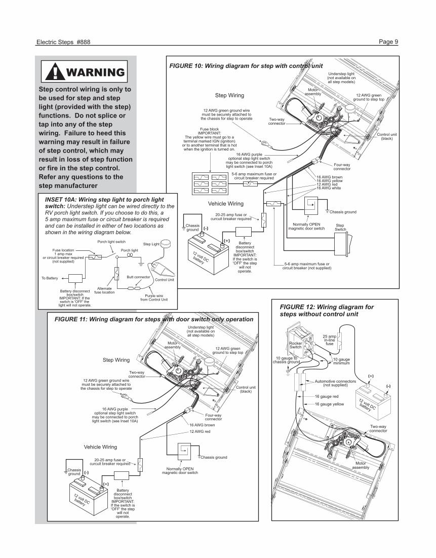
Vehicle Wiring
Step Wiring
Four-wayconnector
16 AWG brown
12 AWG red
Chassis ground
Normally OPENmagnetic door switch
20-25 amp fuse orcurcuit breaker required
Batterydisconnectbox/switch
IMPORTANT:If the switch is'OFF' the step
will notoperate.
Chassisground
12 volt DCbattery
16 AWG purpleoptional step light switch
may be connected to porchlight switch (see Inset 10A)
Motorassembly
Understep light(not available onall step models)
12 AWG greenground to step top
Control unit(black)
Two-wayconnector
12 AWG green ground wiremust be securely attached to
the chassis for step to operate
FIGURE 11: Wiring diagram for steps with door switch only operation
FIGURE 12: Wiring diagram for steps without control unit
12 volt DCbattery
RockerSwitch
16 gauge red
16 gauge yellow
10 gauge tochassis ground
25 ampin-linefuse
Automotive connectors(not supplied)
10 gaugeminimum
Motorassembly
Two-wayconnector
Vehicle Wiring
Motorassembly
Understep light(not available onall step models)
12 AWG greenground to step top
Control unit(black)
Four-wayconnector
16 AWG brown16 AWG yellow12 AWG red16 AWG white
Step Switch
Chassis ground
Normally OPENmagnetic door switch
20-25 amp fuse orcurcuit breaker required
Batterydisconnectbox/switch
IMPORTANT:If the switch is'OFF' the step
will notoperate.
Chassisground
12 volt DCbattery
Fuse blockIMPORTANT:
The yellow wire must go to aterminal marked IGN (ignition)
or to another terminal that is hotwhen the ignition is turned on.
Two-wayconnector
12 AWG green ground wiremust be securely attached to
the chassis for step to operate
16 AWG purpleoptional step light switch
may be connected to porchlight switch (see Inset 10A)
5-6 amp maximum fuse orcircuit breaker required
5-6 amp maximum fuse orcircuit breaker (not supplied)
Step Wiring
FIGURE 10: Wiring diagram for step with control unit
INSET 10A: Wiring step light to porch lightswitch: Understep light can be wired directly to theRV porch light switch. If you choose to do this, a 5 amp maximum fuse or circuit breaker is required and can be installed in either of two locations as shown in the wiring diagram below.
Battery disconnectbox/switch
IMPORTANT: If the switch is 'OFF' the
light will not operate.
Porch light switch Step Light
Control UnitButt connector
Porch light
To Battery
Purple wirefrom Control Unit
Alternatefuse location
Fuse location1 amp max
or circuit breaker required(not supplied)
Step control wiring is only to be used for step and step light (provided with the step) functions. Do not splice or tap into any of the step wiring. Failure to heed this warning may result in failure of step control, which may result in loss of step function or fire in the step control. Refer any questions to the step manufacturer
WARNING!

Electric Steps #888 Page 10
Troubleshooting and Testing Procedures, ContTESTING THE MOTOR
11. Disconnect the two-way connector between the step motor and the control unit. Connect the motor’s red wire to the positive (+) terminal of the battery and touch the motor’s yellow wire to the negative (-) terminal of the battery to extend the step. To retract the step, reverse the connections. If the step extends and retracts during this test, the condition of the step motor is good. NOTE: On steps with reverse polarity plug (Part #1800711) reverse the red and yellow wire connections to perform the previous test.
TESTING THE 4-WAY CONNECTOR
12. To check the main power source, connect a voltmeter between the red wire from the 4-way connector (vehicle half) and the ground terminal at the end of the control unit’s green ground wire (See Figure 13). The reading should be a minimum of 12 volts DC.
If the voltage reading is low, there may be a loose or corroded connection at the battery, a low charge level on the battery itself, or a poor ground. If the voltage reading is zero (0) volts, check the step fuse/circuit breaker, all connections, and the condition of the wiring between the battery and the plug, including the ground connection at the chassis.
13. To check the step switch, connect a voltmeter between the white wire from the 4-way connector (vehicle half) and the terminal at the end of the control unit’s green ground wire (See Figure 14). The reading should be a minimum of 12 volts DC (the same as in Step 12) with the switch in one position, and zero (0) volts DC with the switch in opposite position. NOTE: Refer to vehicle OEM owner’s manual (or OEM Requirements) which will provide the switch position of “on” or “off” for the step lock position.
If the voltmeter reads zero (0) volts when the step switch is in the Automatic Mode position, there is a problem in the step switch circuit.
Check the 6 amp in-line fuse, the step switch itself and the condition of the circuit’s wiring and terminal connections.
14. To check the door switch, connect a voltmeter between the red wire from the 4-way connector (vehicle half) and the brown in the same connector (See Figure 15). The voltage should be a minimum of 12 volts DC (the same as in step 12) when the door is closed and zero (0) volts when the door is open.
If the readings are incorrect, there is a problem with the switch. Check the door switch and the condition of the circuit’s wiring and terminal connections.
Red4-way connector
(vehicle-side)
Ground wire: green ground wire must be attached to vehicle chassis; a good ground is neededfor proper step operation
Voltmeter shouldread 12 volts DC
Red
Brown
4-way connector(vehicle-side)
Voltmeter should read 12 volts DC when dooris closed
Voltmeter should read0 volts DC when door is open
CAUTION!Do not leave the wires connected during this test once the step has cycled either in or out. Failure to remove the wires from the battery will burn out the motor voiding any warranty.
FIGURE 13: Main Power Source
White
4-way connector(vehicle-side)
Ground wire: green ground wire must be attached to vehicle chassis; a good ground is neededfor proper step operation
Voltmeter should read 0 volts DC / stepswitch Automatic Mode or12 volts DC / stepswitch Lock Position.
FIGURE 14: Step Switch FIGURE 15: Door Switch
12
Electric Steps #888 Page 11
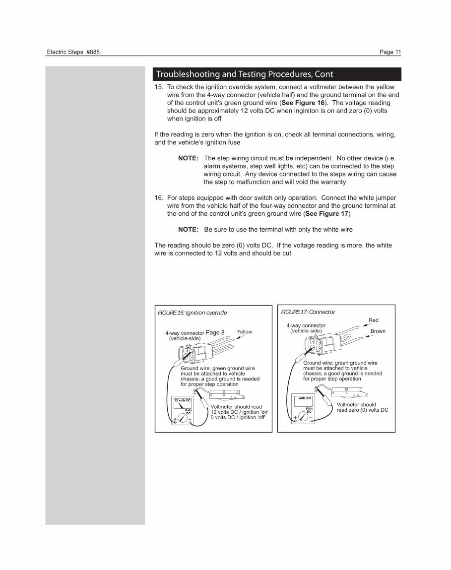
Troubleshooting and Testing Procedures, Cont15. To check the ignition override system, connect a voltmeter between the yellow wire from the 4-way connector (vehicle half) and the ground terminal on the end of the control unit’s green ground wire (See Figure 16). The voltage reading should be approximately 12 volts DC when inginiton is on and zero (0) volts when ignition is off
If the reading is zero when the ignition is on, check all terminal connections, wiring, and the vehicle’s ignition fuse
NOTE: The step wiring circuit must be independent. No other device (i.e. alarm systems, step well lights, etc) can be connected to the step wiring circuit. Any device connected to the steps wiring can cause the step to malfunction and will void the warranty
16. For steps equipped with door switch only operation: Connect the white jumper wire from the vehicle half of the four-way connector and the ground terminal at the end of the control unit’s green ground wire (See Figure 17)
NOTE: Be sure to use the terminal with only the white wire
The reading should be zero (0) volts DC. If the voltage reading is more, the white wire is connected to 12 volts and should be cut
FIGURE 17: ConnectorRed
Brown4-way connector
(vehicle-side)
Ground wire: green ground wire must be attached to vehicle chassis; a good ground is neededfor proper step operation
Voltmeter should read zero (0) volts DC
Page 8
FIGURE 16: Ignition override
Yellow4-way connector(vehicle-side)
Ground wire: green ground wire must be attached to vehicle chassis; a good ground is neededfor proper step operation
Voltmeter should read 12 volts DC / ignition 'on'0 volts DC / ignition 'off'

Electric Steps #888 Page 12
1. We warrant that the equipment is free from defects in material and workmanship under normal use and service. The provisions of this warranty shall not apply to any equipment that has been subject to misuse, negligence, alteration, accident, improper installation (such as the welding of the step to the vehicle frame or mounting brackets), normal deterioration due to wear, cutting of wires, or has been repaired outside our place of business in any way as, in our reasonable judgement, to adversely affect its performance and reliability. 2. The warranty is effective as of the date of sale to the original purchaser and extends two years for parts and labor on step mechanisms and one year for step finish. Since it is the responsibility of the owner to verify the original purchase date, Kwikee recommends that a bill of sale or sales receipt be kept for that purpose. 3. There is no expressed warranty other than the foregoing warranty. THERE ARE NO IMPLIED WARRANTIES OF MERCHANTABILITY OR FITNESS FOR A PARTICULAR PURPOSE. In no event shall Kwikee be liable for any incidental or consequential damages. This warranty gives you specific legal rights. You many also have rights, which vary, from state to state. Some states do not allow the limitations of implied warranties, or the exclusion of incidental or consequential damages, so the above limitations and exclusions may not apply.
WARRANTY GUIDELINES AND PROCEDURES 1. Freight will be prepaid at the UPS ground rate on warranty parts orders with a Kwikee Technical Support verification number. Warranty parts orders requiring expedited shipping (2nd day, 3rd day, next day) will have the freight charged to the service center or owner.
2. Warranty replacement parts will be shipped at no charge to the repair facility, UPS GND prepaid. Parts previously purchased direct from Kwikee will not be reimbursed, but replaced with either a direct or comparable part. 3. Warranties involving labor must adhere to the standard time guide as published. Repairs not listed in the standard time guide will be compensated at areasonable time allowance as determined by Kwikee. Overtime labor will not be honored under warranty. Kwikee will compensate the Authorized Service Center for labor at the service center’s published labor rate if it can be established that the rate is reasonable for the area. 4. Living or travel expenses, telephone, fax, fuel or other related expenses are not covered under warranty.
For questions regarding these warranty procedures or technical assistance, check powergearus.com for current information.
Be sure to visit us online for updates, and downloadable documents.
Kwikee Limited Warranty
Please contact your Selling Dealer or Coach Manufacturer for further information concerning your warranty.