a burst compression and expansion technique for … burst compression and expansion technique for...
TRANSCRIPT

NASA Technical g_moran_dum_ !0_22414........
AIAA-90-0850 ....................
' A Burst Compression and ExpansionTechnique for Variable-Rate Users in
........ Satellite-sWitched TDMA Networks
James M. Budinger .........Lewis Research Center
Cleveland, Ohio
Prepared for the13th International Communication Satellite Systems Conference
sponsored by the American Institute of Aeronautics _and Astronautjc_
Los Angeles, California, March 11-15, 1990
(NASA-TM-IO241_,) A 5URST C_HPRESf;ION AND
_XPANSI_N /FCHN!_UE FOR VAF_IA_LE-RATt_ USERS
IN SAT_LLITF-SnIICHE0 Tf3MA NZTnnRKS (NASA)
lg p CSCL 17_
G3/tT
N90-15983
https://ntrs.nasa.gov/search.jsp?R=19900006667 2018-06-17T19:04:14+00:00Z

...... _ d

A BURST COMPRESSION AND EXPANSION TECHNIQUE FOR VARIABLE-RATE USERSIN SATELLITE-SWITCHED TDMA NETWORKS
James M. BudingerNational Aeronautics and Space Administration
Lewis Research Center
Cleveland, Ohio 44135
Abstract
A burst compression and expansion technique is de-scribed for asynchronously interconnecting variable-data-rate users with cost-efficient ground terminals in a sat-ellite-switched, time-division-multiple-access (SS/TDMA)network. Compression and expansion buffers in eachground terminal convert between lower rate, asynchro-nous, continuous-user data streams and hlgher-rate TDMAbursts synchronized with the satellite-switched timing. The
technique described uses a first-in, first-out (FIFO)memory approach which enables the use of inexpensiveclock sources by both the users and the ground terminalsand obviates the need for elaborate user clock synchroniza-tion processes. A continuous range of data rates fromkilobits per second to that approaching the modulator burstrate (hundreds of megabits per second) can be accom-modated. The technique was developed for use in theNASA Lewis Research Center System Integration, Test,and Evaluation (SITE) facility. Some key features of thetechnique have also been implemented in the groundterminals developed at NASA Lewis for use in on-orbit
evaluation of the Advanced Communications TechnologySatellite (ACTS) high burst rate (HBR) system.
Introduction
Satellite-Switched TDMA
Time-division-multiple-access (TDMA) is a techniquewhereby network users with different data throughputrequirements can equitably and efficiently timeshare thenetwork resources. In a satellite-switched TDMA (SS/-TDMA) network, communication among geographicallydispersed users is enabled through an onboard crosspoint,or matrix switch. The matrix switch routes the bursts of
source user data that are received via uplink antennabeams to downlink beams that illuminate the areas wheredestination users are located. The bursts are timed so that
only one pair of source and destination users are communi-cating at any instant in time. For the duration of theirburst, the full receiving, switching, and transmitting re-sources of the satellite are allocated to them. These re-
sources are divided or time-divlsion-multiplexed among allactive users in the network.
Greater flexibility in interconnecting widely dispersedusers is enabled through the use of hopping beams. Here,multiple uplink and downlink antenna beams are electron-
icaUy switched to cover specific source and destinationlocations simultaneously in a periodic sequence. Sourceand destination users in covered locations communicate
with each other through TDMA ground terminals (seeFig. 1). The Advanced Communications TechnologySatellite (ACTS) under development by the NASA LewisResearch Center will demonstrate the flexibility of SS-/TDMA using multiple hopping beam antennas. 1 For
more information on TDMA systems architecture andterminal implementation see Ref. 2.
FuAu_ _x RECEIVEDER'I'6_) _ BURSTS7
t / I ,,,iTRANSMITTED\ _ _ /_. .t, ,lBURSTS --"x \ "" "_ _ r/ /
_,. // 8 e \\_,,-_"JAk -"Y-,,
LOCATION A _ LOCATION C
GROUND TERMINAL 2
LOCATION B
Fig. 1 Multiple-beam, satellite-switched, time-division-multiple-access(SS/TDMA) network.
A precise method for maintaining timing and synchro-nization among users, their TDMA terminals, the hoppingsatellite antennas, and the onboard matrix switch is
required in order to enable the sequential communicationamong multiple users across the network. This paperaddresses a technique for maintaining timing and synchro-nization among users who have variable-data-rate require-ments and the TDMA network ground terminals. In thisintroductory section, the concept of burst-time plans andTDMA frames is briefly explained, followed by a descrip-tion of the role of compression and expansion buffers in aTDMA terminal. The rationale for supporting variable--data-rate users is provided next, and the section concludesby noting current and potential applications. In subsequentsections of the paper, an overview of the technical ap-proach and its advantages are presented, followed by adiscussion of the sources of clock variation in an SS/-TDMA system and methods used to accommodate them.

Specificobjectivesanddetailsof howthevariable-rateburstsynchronizationtechniquemeetsthoseobjectivesarepresentedin thefinalsection.
Burst-Time Plans
Burst transmissions from all source terminals are time-
multiplexed over the course of a TDMA frame (typically 1to 30 ms in duration) to arrive at the satellite in synchro-nism with the matrix switch timing. To ensure that onlyone burst arrives at the satellite in each time slot, the
timing of burst transmissions is coordinated through apredetermined burst-time plan (BTP) established by a net-work control computer attached to a master control termi-nal. The BTP consists of transmit and receive time slot
assignments for each terminal in the network. The BTPrepeats every TDMA frame and is updated when usersplace new connection and disconnection requests. Forfurther information regarding the generation of BTP's for
a TDMA system see Ref. 3.
Compression and Expansion Buffers
At each source terminal, continuous digital data streamsfrom multiple users are compressed into high-rate burstsfor modulation and transmission at the assigned time slotswithin the TDMA frame (see Fig. 2). Serial data fromeach source user are temporarily converted to a parallelformat and stored in one of several compression buffers.At the assigned time, parallel data are read out of thecompression buffer onto the transmit multiplexed data bus,scrambled, converted to a high-rate, serial data format, andmodulated as a burst. Scrambling (for the purpose ofenergy dispersal within the modulated spectrum) is accom-plished by "exclusive ORing" the user data with a knownpseudorandom sequence on a bit-by-bit basis. Bursts re-ceived by the destination terminal are converted back to aparallel format, descrambled (to restore the original datasequence), and expanded back into continuous datastreams at the original lower data rates and delivered tothe destination users.
USER 1 [El
[ J_ USER21 II USERNI
VALIDWORD i
COUNT ENCODERI _>
tCOMPRESSION h I_
BUFFER,IIII BUFFER2 I I
I BUFFEFIN I
'r
USERINTERFACECONTROLLER
BUFFER
I ORDERWlRE
TDMA H MASTERCONTROLLER CLOCK
f
I DESTINATION h.._USER t 1-_
I USER21 I[ USERN ]
RECEIVE I_ORDERWIREBUFFER
EXPANSION !_
,'l....OUNT DECODERIN
"tTRANSMITMULTIPLEXEDDATA BUS
SCRAMBLER I
I !TO SERIAL
H BURSTMODEM
PARALLEL
,_ FIFO BUFFER/DESCRAMBLER
RECEIVEMULTIPLEXEDDATA BUS
_M M
IRTTER/
Fig. 2 TDMA ground terminal block diagram.

Compression buffers on the transmit side of the TDMAterminal and expansion buffers on the receive side are used(1) as an interface between the continuous, low-rate datastreams of each user and the high-rate burst modem, (2)to enable corrections in transmit burst timing and absorbvariations in receive burst timing to compensate for
satellite motion, and (3) to absorb variations in instan-taneous data rates caused by asynchronous clocks, oscilla-
tor instability, and satellite-motion-induced Dopplerfrequency shifting.
In the terrestrial interface equipment of a TDMAterminal, compression and expansion buffers can be
implemented with either "ping-pong" (on-line, off-line)memories or "first-in, first-out" (FIFO) memories. Ping--pong memories are two banks of memory operating inparallel (see Fig. 3(a)). When one bank is being writteninto at one data rate, the other can be read from atanother data rate. The figure depicts the condition wheninput data are written into "ping" while output data areread from "pong." At the end of each TDMA frame, thestate of the control lines is switched and the two banks of
memories are ping-ponged. The data written into onebank during the previous frame can then be read outduring the current frame.
C
GENERATOR
I tCONTROLLOGIC
INPUT
DATA
MEMORY
(PING)
_E INPUT DATA II_l OUTPUT DATA L___
Fig. 3(a) Simplified block diagram of "ping-pong" buffer memory.
In contrast, FIFO memories appear externally to bedual-ported, elastic storage devices (see Fig. 3(b)). Datawritten into a FIFO memory sequentially at one rate canbe read out in the same sequence at a different ratewithout external generation of write and read addresses.
WRITEcLoCKI wRITE I ,,.
WR--E-_AnermAT'ONII _ _ ]
DATA OUTPUTDATA
Fig. 3(b) Simplified block diagram of FIFO buffer memory.
Only half of the memory locations and data buffersrequired for a ping-pong implementation are needed forthe same data throughput capability in a FIFO memoryimplementation. Even though the amount of integratedcircuit memory is no longer considered to be a cost driverin digital systems, the FIFO memory approach to compres-sion and expansion buffer implementation offers severaladvantages over the ping-pong memory approach. Themost significant of these is its ability to support asynchro-nous, variable-rate users with minimal data latency (delaywithin the buffer memory itself). Internal arbitrationbetween the FIFO memory's write and read cycles, and thesequential flow of data through a shallow FIFO memory,are the two key features exploited by the variable-data-
-rate compression and expansion buffer technique de-scribed in this paper.
Variable-Rate Users
In many TDMA satellite networks, only user data ratesthat are nearly synchronous submultiples of the networkmaster clock can be accommodated. In addition, thefrequency of both the user and terminal clocks must be
contrplle_ to an accuracy and stability of typically+10"°/s. '* To ensure proper burst arrival time at the satel-lite, the ground terminal may be required to synchronize its
modulator burst clock to a network master clock having astability of +10"8/s or higher. For a high-efficiencyTDMA system with burst rates of several hundred mega-
bits per second, synchronization to a master clock to within+10"10/s may be required. In general, for a given stabili-ty, the cost of an oscillator increases with its outputfrequency. An SS/TDMA network that supports a contin-uum of user data rates (from tens or hundreds of kilobitsper second to nearly the modulator burst rate), all of whichare asynchronous with the network master clock, and
places minimal requirements on short-gnd long-term clockaccuracy and stability (typically +10"*/s), can provide a
varietyofnew communications services and reduce trafficterminal production and maintenance costs. At the sametime, all other terminal subsystems can operate in synchro-nism with a single master clock, free-running at the modu-lator burst rate. A variable rate, burst compression andexpansion technique is required to realize this potential.
In the tcchnique described in this paper, all user data aretransferred to and from the ground terminal as contin-uous, serial data streams regardless of the information rate,content, format, or framing. The source users' bit clocksare asynchronous with respect to the terminal's singlemaster clock. TDMA networks are well suited to commu-
nications with high data throughput (hundreds of megabitsper second). TDMA frame formats and terminals de-signed to exploit the flexibility of this technique will extendmany of the advantages of TDMA communications to awide range of low-to-medium data rate users (hundreds of
kilobits to a few megabits per second) with low-cost digitalterminals.
Applications
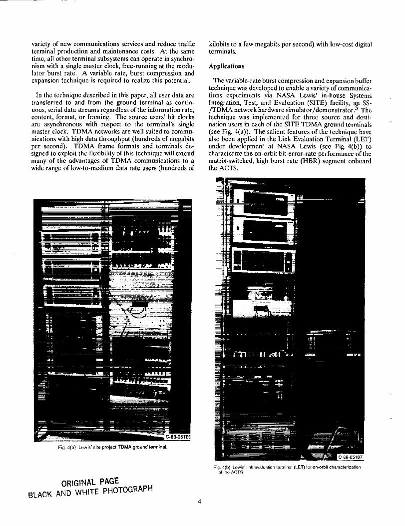
The variable-rate burst compression and expansion buffertechnique was developed to enable a variety of communica-tions experiments via NASA Lewis' in-house Systemsintegration, Test, and Evaluation (SITE) facility, an SS-/TDMA network hardware simulator/demonstrator. 5 The
technique was implemented for three source and desti-nation users in each of the SITE TDMA ground terminals(see Fig. 4(a)). The salicnt features of the technique have
also been applied in the Link Evaluation Terminal (LET)under development at NASA Lewis (see Fig. 4(b)) tocharacterize the on-orbit bit-error-rate performance of thematrix-switched, high burst rate (HBR) segment onboardthe ACTS.
Fig. 4(a) Lewis' site project TDMA ground terminal,
ORIGINAL PAGE
BLACK AND WHITE PHOTOGRAPH
c-sB-0sle7
Fig.4(b) Lewis'linkevaluationterminal(LET)foron-orbitcharacterizationofthe ACTS.

The technique is also suitable for use in packet-switchednetworks with variable-length data packets where the slightadditional overhead required for its implementation couldbe included in the packet headers. Hardware demonstra-tion models for a processing satellite network with onboardpacket-switching capability will be developed in futurephases of the SITE project. Implementation ease and costefficiency of digital ground terminals and experimentflexibility were the major development goals. Expandeduser support capabilities and reduced requirements on userand terminal clock accuracy, stability, and synchronizationprocesses are the byproducts of the development.
Technical Approach
An intrinsic requirement of SS/TDMA networks is tomaintain precise control of timing and synchronizationacross the network in order to effectively and efficientlyutilize the ground and space resources. Network userswith the need for communications services at a variety ofasynchronous data rates present a challenge to the design-ers of TDMA terminals -- how can an inherently synchro-nous space communications system appear to be nearlytransparent to the asynchronous user? In this section, thesalient features of the variable-rate compression and ex-pansion buffer technique are presented along with someadvantages the technique offers to existing and potentialservice users.
Variable-Rate Technique Overview
To support multiple users with a wide range of asynchro-nous data rates, the number of bits of user data trans-mitted by the source terminal from frame to frame mustvary. At the destination terminal, the regenerated bit clockdelivered to the user must replicate the frequency andstability of the source user. The key feature of the tech-nique is to group the number of lower rate user data bitsreceived by the source terminal over roughly one frameperiod into an equivalent number of higher bit rate validdata words per frame and thereby "quantize" the frame-to--frame variation in the number of valid data bits per frameinto one-word increments. This grouping of user data intowords is performed by the compression buffer; continuoususer data are written into the FIFO memory at the user'sclock rate and are read out at the burst modulator clock
rate. Each transmitted burst is an integer number ofwords in duration. On a frame-to-frame basis, the numberof valid words in the burst may increase or decrease by onefrom some nominal number that represents the approxi-mate data throughput.
Every continuous data rate (in bits per second) withinthe supported range of rates is converted into an equivalentnumber of valid data words per frame. The word widthinternal to the ground terminal is a function of the datarates to be processed and the speed of available memory.The integer portion of the number of valid data words perframe is referred to as the nominal word count (NWC)(see Fig. 5). The source terminal inserts a short codeword,
1n BITS
1
called a valid word count (VWC), in front of each databurst to inform the destination terminal if the number ofvalid words in the burst is different from the NWC value
it is expecting. For example, before the source user beginssending data, none of the words in the burst are valid andthe VWC indicates this condition. Transmission of valid
bursts (NWC in duration) will not begin until a numberof words at least equal to the NWC is available in thecompression buffer. During each transmit frame, addition-al bits beyond the integer number of valid words (theNWC) accumulate in the compression FIFO buffer of thesource terminal, thus increasing the relative "fill level."This continues until enough bits have accumulated duringsome later frame to form an additional word, which can betransmitted along with NWC valid words during the nextframe. The VWC preceding that burst will then indicatethat one word more than the NWC has been transmitted.
_'_ FRAME
1BtTI 1 I 2 I a I"'1 N I N+I I'" =t
t _TAATUSERRATEWORDH
[ !' I:=:[gl .,
PARALLEL DATA AT BURST RATE
Fig. 5 Conversion of continuous valid data bits to an equivalent numberof valid data words per frame,
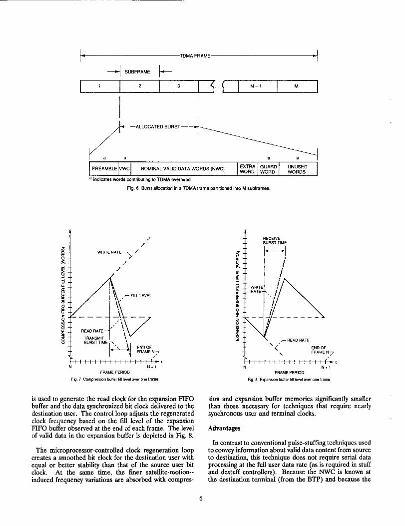
The BTP for the source and destination terminals, aswell as the onboard matrix switch state tables, must reflectan assignment of a time slot several words longer induration than that required to transmit the NWC alone.The assigned time slot must be long enough to contain theburst overhead bits (the demodulator preamble and aguard time between bursts), and one additional word toaccommodate periodically both the decimal fraction ofvalid words per frame and any user clock frequencyvariations. In practice, the TDMA frame may be parti-tioned into smaller subframes of a convenient number ofwords in duration to ease BTP assignments. In such acase, the smallest number of subframes that contain thelongest possible burst for that data rate (including TDMAoverhead) are assigned (see Fig. 6).
The accumulation of continuous user data in the com-
pression buffer over one frame (before, during, and afterburst transmission) is depicted in the graph shown inFig. 7. The effect of bit and word quantization on fill levelis removed for clarity.
In the destination terminal, a control loop subroutineexecuting in the user interface controller varies the fre-quency of a voltage-controlled oscillator (VCO). The VCO
' I
l
TDMA FRAME
SUBFRAME I-_'---
-1
2 i 3 1t.,.;I "-1 I M I
a_a= --ALLOCATED BURST___
[_REAMB'EVWCI .OM,.A'VA',OOATAWO.OS<.WC,]_OOAROwoRDWO.Oa Indicates words contributing to TDMA overhead
Fig. 6 Burst allocation in a TDMA frame partitioned into M subframes.
UNUSED IWORDS
Q
,,,r.
==,,+_z
++,,,j0
//
/
WRITE RATE _ i
2/
//
/--- FfLL LEVEL
°_£2g,-2__T1
BURST TIME_. END OF
FRAME N -7
I I I I I I I I I I I I ,_,_ ! ,r_tN N+I
FRAME PERIOD
F=:J. 7 Compression buffer fin level over one frame.
_E
(z:
,,=u..
==
o.
• WRITERATE -
\
RECEIVE
BURST TIME
/!
r READ RATE
% END OF_. FRAME N -7#
N,+.f
FRAME PERIOD
Fig. 8 Expansion buffer fill level ever ene frame.
is used to generate the read clock for the expansion FIFObuffer and the data synchronized bit clock delivered to thedestination user. The control loop adjusts the regeneratedclock frequency based on the t'dl level of the expansionFIFO buffer observed at the end of each frame. The level
of valid data in the expansion buffer is depicted in Fig. 8.
The microprocessor-controlled clock regeneration loopcreates a smoothed bit clock for the destination user with
equal or better stability than that of the source user bitclock. At the same time, the freer satellite-motion--induced frequency variations are absorbed with compres-
sion and expansion buffer memories significantly smallerthan those necessary for techniques that require nearlysynchronous user and terminal clocks.
Advantages
In contrast to conventional pulse-stuffing techniques usedto convey information about valid data content from sourceto destination, this technique does not require serial dataprocessing at the full user data rate (as is required in stuffand destuff controllers). Because the NWC is known atthe destination terminal (from the BTP) and because the

VWC codewordcanbe error encoded,the techniquesignificantlyreducesthedecodingerrorsintroducedduringpulsedestuffingtechniques.Thistechniquealsoavoidstheabrupt,short-termtimingjitterintroducedbyconventionalpulsestuffingat prescribedtimelocations.
Thevariabledatarate,compressionandexpansionbuffertechnique,asdesignedfor TDMAterminalsof theSITEfacility,accommodatesanyuserdataratefrom256kb/stonearlythe221Mb/smodulatorburstrate.Userdataaredelayedbynomorethantwoframeperiodsineachbufferregardlessof theinformationbit rate.Minimaladditionalbitsareaddedto theTDMAoverhead.Thevariable-ratebuffertechniquereadilyabsorbsuserbit clockinstability(aspooras+10-4/s)andthefreesatellite-motion-inducedDopplersh_ (on the orderof +10-U/s) without gen-erating slips in frame timing. The relaxed clock stabilityrequirement and asynchronous operation offer groundsegment cost savings and data rate flexibility unavailable toSS/TDMA networks that require synchronous or nearlysynchronous operation.
Sources of Clock Variation
The TDMA terminal's compression buffers must absorbor otherwise accommodate apparent timing and frequencyvariations in the serial data rate received from the source
users. Likewise, the expansion buffers must accept similarvariations in the arrival time and frequency of the high-bit--rate bursts received via the satellite. The variation in rangebetween the on-orbit satellite and the ground terminals isthe primary source of clock or timing variation. The twoprimary sources of frequency variation in a SS/TDMAsystem are the rate at which the range delay varies and theoscillator imperfections. Frequency variation from anysource can also lead to bit and frame timing variation withrespect to a clock at the destination. The consequences ofeach of these sources of variation and their effect on thedesign and implementation of compression and expansionbuffers will be discussed in the sections that follow.
Range Delay Variation
Compression and expansion buffers can be used toabsorb the bit timing fluctuations caused by variation inthe distance between the terminal and the satellite. The
nominal distance or "range" between a ground terminaland a satellite in a geostationary orbit (a circular orbit ofradius 42 242 km that is lying in the Earth's equatorialplane) can be computed from a set of orbital mechanicsequations for a specific location on the surface of theEarth. 6 The average range between NASA Lewis' geosta-tionary satellite ACTS (to be located at 100° west longi-tude), and the closest and farthest major cities in th_contiguous 48 states is expected to be about 37 660 km. _A signal traversing this distance at the speed of light wouldexperience a nominal range delay of about 125 ms. For atypical satellite link, variations in the range delay over a24-hr period (primarily due to orbit inclination, eccen-tricity, and atmospheric and ionospheric variations) can
reach a maximum value on the order of a few millisec-onds. 8
More tightly station-kept processing satellites withmultiple-beam antennas like the ACTS will yield signifi-cantly lower maximum range delay variation. For example,the maximum range delay variation (in seconds) is equal tothe nominal maximum range variation over one day, dm(in meters), divided by the velocity of propagation, c [_meters per second):
Td = dmax/C
For the ACTS, a nominal maximum range variation of+20km has been specified. Therefore, the maximum rangedelay variation is:
T d = 40x103 (m)/3xl08 (m/s) = 133x10-6 s
The number of bits of compression and expansion buffermemory, N v, necessary to accommodate the range delayvariation at a data throughput equal to the modulator burstrate is the maximum range delay variation, T d (in seconds)divided by the modulator bit period, T b (in seconds perbit):
Nv= Td/T b
The modulator burst rate used in both the ACTS linkevaluation terminal (LET) and the SITE facility is 221.184Mb/s. Tb is the inverse of this rate, or 4.52 ns/b. So forthis burst rate:
N v -- 133x10 -6 (s)/4.52x10 -9 (s/b) = 29.4x10³ b
Hence, it would appear that modest 32 kb memories wouldbe sufficient for the compression and expansion buffers inany TDMA terminals to communicate via the ACTS usinga burst rate of 221.184 Mb/s. If the range delay variationhad been closer to that of the typical satellite, say 10 msfor example, the same burst rate would have requiredbuffers with over 2 Mb of storage each. While neither ofthese examples presents a difficult or costly memoryrequirement, the problem with this approach to bufferdesign is that burst transmission cannot begin until thecompression buffer reaches the half-full level at themidpoint of the range delay variation. If the compressionbuffer is not Idled to this point, then, as the satellite movesaway from the source terminal and burst transmissionoccurs earlier (to insure correct arrival time at the satel-lite), the compression buffer will be gradually depleteduntil it is empty. This will result in a burst containinginvalid data. Conversely, if the half-fuU condition is notestablished at the correct time, the buffer can just as easilyoverflow as the satellite continues to move toward thesource terminal. A similar condition must be established
in the expansion buffers at the destination terminal.
The impact of delaying user data in conventional com-pression and expansion buffers until the half-full conditionis reached becomes severe for low-data-rate users because

the buffers must be designed to accommodate the maxi-
mum data throughput (nearly the modulator burst rate)and it may take hundreds of TDMA frames before trans-mission can begin. However, by using the variable-rateburst compression and expansion technique, the fill level isset according to the user's data rate to minimize data delaywithin the ground terminal. The fill level is roughlyproportional to the ratio of the user's data rate to themodulator burst rate. Each data rate experiences the samethroughput delay as all others.
Variable Frame Duration Technique
To accommodate the effect of range delay variation onTDMA frame timing a second technique is used. Eachterminal autonomously adjusts its transmit and receiveframe duration to ensure proper burst timing at the
satellite (see Fig. 9). As the range for a specific terminaldecreases, it will simultaneously increase its transmit frame
counters 1-bit period at a time (thereby delaying its bursttransmission), and decrease its receive frame counters by1-bit period as well (thereby anticipating the early arrival
of the burst). The opposite adjustment takes place for anincrease in range delay. This technique requires that aportion of each source terminal's burst transmission belooped back to that terminal for closed-loop timingadjustment.
__ dl"
d2-..J.dU.I1-.<o_
P._J<_z
I...-
ATtl: ¢ !.,-///Iz.//, o ,_
,,_ INCREASED FRAME
AT t2: _ : .... t////////,,_
I-- NOMINAL RANGE
(_ (ATtl)
/ .L _ DECREASED RANGE
TRAN//__SMITTIMES RECEIVE TIMES
/ / '_ "_ =- TIME
tl t2 tl 12
'DF ME
TRANSMIT TIMING RECEIVE TIMING
Fig. 9 Ground terminal transmit and receive frame duration adjustment tomaintain burst timing during range variation.
Occasionally increasing or decreasing the frame countersby 1-bit count is accomplished through a variable count
word generator (VCWG). By using the ground terminal'ssingle high-speed clock (the modulator input bit clock), theVCWG can create word edges with 63-, 64-, 65-, or 56-bitperiods per word. The transmit and receive frame count-ers can insert a 1-bit shortened (63-bit), normal (64-bit), ori-bit extended (65-bit) word as the unused "guard word" at
the end of the frame. During initial TDMA terminalacquisition, this variable frame duration technique is alsoemployed to reduce the complexity of ground terminal andonboard matrix switch timing synchronization. There, theVCWG is set to provide an 8-bit shortened (56-bit) wordat the end of each frame. This coarse timing adjustmentis used to search for correct timing with respect to refer-ence bursts transmitted by a master control terminal.
The burst demodulator has the ability to produce correctdata as long as the burst arrives within some timingwindow, typically on the order of tens of bits in duration.Any burst arrival time variance acceptable to the demod-ulator but not compensated for by the variable frameduration technique is absorbed in a shallow FIFO bufferthat precedes the descrambler. Only a few words deep onaverage, a single FIFO buffer at this location enables allexpansion buffers attached to the received data multi-plexed bus to operate in synchronism with the terminal'smaster clock (see Fig. 2).
If this technique is used, only one master clock is re-quired for each terminal, and with self-adjustment of bursttiming, the ground terminal's single oscillator can operatewith minimal frequency adjustment (to correct onlylong-term aging effects). This technique is used in boththe SITE ground terminals and the LET. Under the SITEproject, a range delay simulator capable of fixed andvariable delay of data at the modulator burst rate wasdeveloped. 9 The range delay simulator is used to evaluate
the performance of this technique. Further details of thevariable frame duration technique are beyond the scope ofthis paper. Nevertheless, by using this technique, rangedelay variation is handled effectively with minimal depthbuffer memories and uniform data transport delay throughthe ground terminal.
Rate of Range Delay Variation
The destination terminal must absorb the apparentfrequency variations caused by Doppler shifting of the
signal through the moving satellite. The rate of rangedelay variation determines the apparent shift in receivedfrequency at the destination terminal. The receivedfrequency shift will be different for bursts received fromdifferent users since each source terminal will experiencea unique uplink range variation. The satellite may be mov-ing toward one source terminal at the same instant it ismoving away from another. An additional Doppler shift(likely to be different in magnitude and/or direction from
the uplink Doppler shift) will be imposed on all downlinkbursts received at each destination terminal based on
specific range delay variation experienced by that terminal.Doppler shift in frequency of the received bursts is indistin-guishable from the inaccuracy and instability of each sourceterminal's modulator burst oscillator (an oven-stabilized,
voltage-controlled crystal oscillator (VCXO) operating at221.184 MHz). The magnitude of the Doppler shift, likethe oscillator instability at that high a frequency, is quitesmall (on the order of a few nanoseconds per second).

The frequency shift of bursts received by the destinationterminal is minimal if the satellite is moving at the samerate in opposite directions from the source and destination
terminals. It is maximal for the opposite condition. Themaximum clock frequency variation due to Doppler shift,F D (expressed in bits per second), is equal to twice themaximum satellite range rate, R. (in meters per second),times the modulator burst rate, __ (in bits per second),divided by the velocity of propagat'_on, c (in meters persecond):
F D = 2RrRm/c
The maximum range rate specified for the ACTS is +1.2m/s and the modulator burst rate is once again 221.184Mb/s. Therefore:
F D = 2(1.2)(221.184x10⁶)/(3x108) = 1.77 b/s
At the maximum rate of range variation, a 1-bit period
appears to accumulate or to be depleted every 1/F D =0.56 s. With a frame duration of 1 ms, it takes at least1770 frames for the variation to be observed. Over a 12-hr
period, however, a ground terminal in the ACTS networkmay observe as much as 30 km of variation in range. Ata burst rate of nominally 220 Mb/s, about 22 kb appear toaccumulate or be depleted over that time. An importantfeature of the variable-rate compression and expansionbuffer technique used in conjunction with the variableframe duration technique is that the subtle yet cumulativeeffects of Doppler shift and modulator clock inaccuracyand instability are readily absorbed without modification tothe design.
User Clock Imperfections
One of the primary reasons for the development of the
variable-rate compression and expansion buffer techniquewas to enable the use of inexpensive user bit clock sourceswith no frequency control loop across the user/groundterminal interface. The ground terminal will accept thesource user's digital data stream and synchronized bitclock, and deliver the same digital data stream and aregenerated, synchronized bit clock to the destination user.To process the serial data streams in this fashion, the com-
pression buffer must absorb the frequency inaccuraciesand instabilities of the users' bit clocks within some mini-mal specification limits.
Any oscillators used to generate bit clocks will exhibitsome level of degradation from ideal oscillators in threesignificant parameters:
(1) Accuracy - how close the oscillator output frequencyis to a desired frequency;
(2) Reproducibility - how well two sources can be ad-
justed to generate the same frequency, or onesource can repeatedly generate the same frequency;,and
(3) Short- and long-term _ - frequency variationover time due to random internally generated noise
and drift created by component aging and tem-perature effects.
The cost of a clock-generation subsystem increases withincreasingly stringent specifications on each of these three
parameters. The least expensive approach allows forfree-running oscillators in the source user's equipment,moderately accurate and stable modem oscillators, andsimple control loops in the clock regeneration subsystemof the destination terminal.
When applied to the design and development of theTDMA ground terminal's terrestrial (user) interfaceequipment, the measure of these performance parametersis somewhat different than those specified by commercialoscillator manufacturers. Stability is typically measured
over 1 s for the short-term parameter and over 1 day forthe long term. In the TDMA user interface, short-termstability is relative to the TDMA frame duration. Theground terminal has the opportunity to "resynchronize" itscounters at TDMA frame boundaries. In the short term,an oscillator need only meet a specified stability overone-frame period, typically tens of milliseconds. Over sucha short period, temperature stability is of no consequence.Typical frequency stability over a temperature range of 0to 50 *C for crystal oscillators varies from + 10-6 in uncom-
pensated products to +10 -9 for oven-_ontrolled pack-ages. 10,11 Over a short_erm on the order of hundreds of
milliseconds, +5x10 -11 stability is achievable. The effectsof long-term stability, accuracy, and reproducibility areindistinguishable from each other in the proposed vari-able-rate technique. Adjustments in the amount of valid
data contained in a burst from the source terminal, alongwith the control loop used to regenerate the user clock inthe destination terminal, treat the observable effect of
these degradations identically.
Timing Slips
The TDMA terminal is required to absorb or otherwisecontrol the significant effects of bit and frame timing slipson the digital data stream. These slips occur when phasealignment cannot be maintained between two clocks acrossan interface - in this case, between the terrestrial user and
the TDMA terminal. The result of a timing slip is eithera bit insertion or deletion into or out of the digital datastream. Neither condition is desirable from a user's
standpoint, but if well-controlled and documented, either
may be acceptable. The variable-rate compression andexpansion technique circumvents the timing slip conditioncompletely.
One common but expensive technique used to controlthis condition is plesiochronous operation. 12 This tech-
nique requires "nearly synchronous," yet independentlyoperating, oscillators on either side of the interface. Both
the user and terminal clock sources must be sufficientlystable and accurate so as to avoid the need for their con-
tinuous synchronization. Expensive cesium beam oscilla-tors with an accuracy, reproducibility, and long-term sta-bility on the order of+lxl0 -11 are typically required. The
9

discrepancyinbit timingis allowed to build up over manyhours or many days depending upon the relative accuracy
and stability of the two oscillators. At a specific, prear-ranged frame or time during that day, the frame timing isrealigned or "slipped." However, a certain minimum periodbetween frame timing slips must be maintained and
tolerated by the users. The frame timing slip period, Sf (in
days), is a function., of the bit clock rate, Rb (in bits. persecond), its stabihty, WRb/Rb, and the frame duration, Nf(in bits). Using a conversioffof 86 400 s/day:
Sf = (1/Rb)(Rb/WRb)(Nf)(1/86 400)
For example, a 2.048 Mb/s multiplexed system with a+ 10 -11 stable clock and 256 bit frames will experience aTame timing slip about once every 72 days. 13 During the
time set aside for frame timing slips, no user data may besent. In effect, the network runs asynchronously betweentiming corrections.
Disadvantages of Pleslochronous Operation
The plesiochronous synchronization technique is veryreliable, is easy to expand throughout a growing network,and allows independent, internal synchronization tech-niques to be employed within subnetworks of internationalnetworks. However, plesiochronous operation requiresaccurate (+10 -11) and therefore expensive clock sourcesat each node. For a lower data rate user in a cost efficient
satellite network, lower stability clock sources within the
user interface equipment are desirable. For example, aterrestrial user connected to the satellite network via a
TDMA ground terminal might request a DS1 level serviceconnection)vith a bit rate of 1.544 Mb/s, a clock stabilityof +._50x10"°, and a 193 bit frame. 14 One frame of mis-
alignment could occur about every 30 ms. In a practical
system, hundreds or even thousands of frames of misalign-ment would have to be absorbed before correction could
occur.
In plesiochronous operation, the longer the periodbetween timing alignment, the larger the required compres-sion and expansion buffers. The buffers must be sized toaccommodate the asynchronism in bit clock timing over thelong periods between time alignment. The buffer depth isrelated to: (1) the minimum acceptable interval betweentiming slips (which is also a function of path delay variationdue to satellite motion and atmospheric and ionosphericconditions); and (2) accumulated timing errors between theclocks on either side of the interface. For this reason,
compression and expansion buffers designed for use in theINTELSAT system combine the functions of Doppler ef-fects compensation and plesiochronous timing alignment,and are referred to as alignment and Doppler buffers. 15
Plesiochronous operation requires the most accurateclocks of the various disciplined and nondisciplined syn-chronization techniques, 16 and controlled timing slips must
be allowed to occur periodically. The variable rate com-pression and expansion buffer technique described in thispaper offers the significant advantage of supporting
multiple-user data rates with clocks that are asynchronouswith respect to the ground terminal clock, without thedisadvantages of expensive clock sources, limited data ratesupport, frame timing slips, and large buffer size.
Variable Rate Synchronization Technique
Given the brief background on the sources and effects ofclock variation on TDMA ground terminals presentedabove, the implementation approach for the variable-ratetechnique can now be presented. In this section of the pa-per, six specific operational objectives are identified, andthe details of how the variable-rate compression and ex-pansion buffers meet these objectives are described.
Master-slave disciplined synchronization techniques areused in the SITE ground network and switching transpon-der simulation. Each ground terminal's transmit andreceive counters are indirectly slaved or synchronized tothe master clock timing (on board the satellite) throughperiodic in-band reception of reference bursts from amaster control terminal (MCT). The MCT's referenceclock is slaved to the onboard master dock. The matrix
switch state changes are also synchronous with the onboardmaster clock.
The transmit side of the terminal accepts the bit clocktiming from each source user without any adjustment.There, burst compression buffers (one for each user)absorb the asynchronism between users' docks and themodulator burst clock. The receive side of the terminal
accepts bit clock timing from the demodulator, also withoutany adjustment. The shallow FIFO buffer following thedemodulator absorbs the instantaneous asynchronismbetween the clocks derived from received bursts and the
ground terminal's master clock. The burst expansionbuffers (also one for each user) absorb the frame-to-framefluctuation in valid data fill level so that stable bit clocks
can be regenerated and delivered to the destination users.
Note that since received bursts originate from varioussource terminals in the network, each will exhibit some
measure of frequency inaccuracy (associated with themodulator burst clock) and Doppler shifting (unique to thesource terminal's uplink range variation). Accordingly, theclocks derived from each successive burst are completelyindependent in frequency, amplitude, and arrival time. Theburst demodulator must be capable of rapid clock recoveryand valid data identification.
In the TDMA terminal, the compression and expansion
buffers, along with their controllers, are implemented aspart of the user interface equipment as shown in the blockdiagram of Fig. 10. The appropriate compression andexpansion buffers are multiplexed onto the transmit andreceive data busses, respectively, according to the burst--time plan. The ground terminal's master clock (operatingat the modulator burst rate) is used to create both thecompression buffer read clock and the expansion bufferwrite clock.
10

ii
O
trLUt/)
Udon-
Ow
SERIAL DATA =IBIT CLOCK SERIAL
:I '°VALID DATA PARALLEL
COMPRESSION BUFFER
REQUEST
GRANT
DESTINATION
DATA RATE
USERINTERFACECONTROLLER
CONTROL
TDMA I _CONTROLLER
PARALLEL DATA
WORD CLOCK (WRITE)
VALID DATA
FIFOBUFFERMEMORY
1/
ARBITRATIONLOGIC
FILL LEVEL [
SET
POINT--_ > LATCH
•-_ FILLLEVEL
---P • LATCH
END OF FRAME
CONTROL
UP/DOWNCOUNTER
READONLYMEMORY
VWC DATA
VALID WORDCOUNTENCODER
TRANSMITMULTIPLEX-CONTROLLER
USER
READ
VWC
Fig. 10 Block diagram showing one compress]on buffer (one for each user) and source user interface.
CO
"_UJI0z o
Objectives
The primary objectives in the design of the SITE TDMAterminal compression and expansion bufferswere:
(1) Variable-rate user interfac¢ - accommodate user datarates from 256 kb/s to nearly the modulator burstrate of 221.184 Mb/s with asynchronous docks andminimal stability requirements;
(2) Clock regeneral;ion - regenerate and deliver to thedestination user a bit clock synchronized to thedelivered bit stream with equal or better stabilitythan that of the source user dock, while absorbingthe effects of modulator oscillator instability andrange variation;
(3) Bit-count inte__ity - deliver to the destination userexactly the same valid data bit stream that wasreceived from the source user with no lost or dupli-cated bits (forward error correction is not addressedhere) thereby eliminating timing slips;
(4) Minimal overhead - minimize overhead bits thatcontribute TDMA frame inefficiency;,
(5) Fixed bUffer delay - provide an equal propagation
delay (quantized to an integer number of frameperiods) through the TDMA terminal regardless ofthe user's data rate; and
(6) Minimum memory, requirements - eliminate on-line,off-line (ping-ponged) burst buffer memories in favorof minimal depth FIFO memories.
The mechanisms for satis_hng each of these objectives inthe design and implementation of compression and expan-sion buffers are described in the sections that follow.
Variable-User Data Rates
For the compression FIFO buffer, a number of fill-levelthresholds (in words) are established over a binary loga-rithmic scale (powers of two) to cover the ranges of userinformation data rates. As stated earlier, the compressionbuffer threshold value must be reached before transmission
of valid data bursts can begin. The thresholds are afunction of the modulator burst rate, R_ (in bits persecond), the TDMA terminal's internal worU_width, W (in
bits per word), and the frame duration, Tf (in seconds perframe). For example, the data rate ranges and thresholdsshown in Table 1 are compatible with the SITE TDMA
11

terminal's 221.184 Mb/s modulator and 64-bit wideserial-to-parallel (S/P) and parallel-to-serial (P/S) con-verters, operating with a 250 ms TDMA frame period.
T_BLE I. - SUPPORTED USER DATA RATES _NO fIFO _bF:ER J_L_ES
Data rate range NWC values 'hresnold [ SetQo;n_
(Mb/s) (wOrdS per frame) wor_s; I :he×l
0,256 to 0,512
.512 to 1.024
1.024 to 2,048
2.048 to _.og64.096 to 3.192
8.192 to 16.384
16.384 to 32.768
32,768 to 55.536
65.536 to 131.Q72
131.072 to 221,:B4 a
l to 22 to 4
d to 3
3 to i6
:6 to 32I
32 to 64 I54 tO 128 _
i26 _o 256
256 to 512Si2 to 1024
!
2
3
76
32
54
"2B
256SIX
_024
aLimited to modulator burst rate.
The user data rates are also grouped into binary loga-
rithmic ranges. For this example, the range limits arepowers of two times a base of 1 kb/s, starting with thelowest supported data rate of 256 kb/s. The mapping ofuser data rates to the binary FIFO threshold levels shownin Table 1 guarantees that any data rate within each rangewill fill the FIFO to a point greater than the thresholdvalue within three-frame periods regardless of when during
the transmit frame the user data stream begins. Thisthreshold feature is necessary to ensure nearly identicalbuffer delay (nominally two frames' worth) for the fullrange of supported user data rates. The setpoint is ahexadecimal value used by the TDMA controller toprepare the compression FIFO buffer for operation and todetermine the amount of capacity to be requested forconnection.
Nominal Word Count
Every supported user data rate, R u (in bits per second),can be expressed as an equivalent word rate, R w (in wordsper frame), by multiplying by the frame duration, Tf, anddividing by the word width, W:
R w = RuTf/W
The nominal word count (NWC) corresponding to eachinformation rate is dermed as the largest integer less thanR.. The NWC represents the approximate number of
Wwords received from the source user during each frame.The compression and expansion buffer threshold value isequal to the upper limit of NWC values corresponding tothe appropriate data rate range as shown in Table 1.
The TDMA controller of the source terminal sends anorderwire via the satellite to the master control terminal
(MCT) requesting a new connection with sufficient capacityto contain a burst a few words larger than the NWC. Therequested burst size must accommodate the fractionalvalue of the equivalent word rate and its upper tolerance(due to user clock instability), and the TDMA overhead ofpreamble and guard times. In practice, capacity is re-quested and allocated in uniformly-sized subframes to easeburst-time plan generation in a demand-asslgned corn-
munications network. If sufficient capacity is available, the
MCT grants the request and instructs the appropriatedestination ground terminal to prepare for a connectionwith the same capacity between the specific source anddestination users. At the destination terminal, the ap-propriate threshold setpoint is initialized in the exparmionbuffer based on the NWC received in the orderwire.
Valid Word Count
Once the NWC is known by the destination terminal,only the change from the NWC value need be sent alongwith each data burst. In the variable-rate buffer technique,this change is called the valid word count (VWC). TheVWC can assume four possible values: (1) no words in theburst are valid (transmission has not begun or has ended);(2) a number of words equal to the NWC are valid; (3) atotal of one word less than the VWC are valid; and (4) atotal of one word more than the VWC are valid. The
VWC value is heavily forward-error-correction encoded toensure correct reception at the destination terminal. Inthe SITE terminals, the four possible VWC values areencoded into four 12-bit codewords by a simple hardwarelookup table called the VWC encoder (see Fig. 10) andinserted into a header that precedes the data portion of
each burst (see Fig. 6). For improved TDMA efficiency,either a higher code rate could be used, or more check bitscould be assigned to the less-likely-occurring VWC's. If aVWC codeword is not correctable, the value indicating thateither the NWC is valid or none are valid is assumed
depending upon whether or not valid burst communicationhas already begun.
Once the compression buffer threshold value has beenreached (as observed at the end of each transmit frame),transmission of valid data bursts can begin during the nextframe. For an example with the conditions listed inTable 2, the valid data fill level as a function of time is
depicted in the graph shown in Fig. 11. Notice that thetmer's data stream does not need to begin at any specifictime during the TDMA frame and that transmission willnot begin until the threshold has been reached.
TABLE 2
Parameter
User data rate. Mb/s
Equivalent word rate, words per_rame
Nominal _ord count, aordsThreshold _alue, words
Burst rate _read), words per Frame
Frame duration, _s
laiue
5.J3]5
Z50
Frame [ Startinglevel
N 0.000
N _ 1 4,500
N + 2 I0.531
N + 3 ).563
N ÷ 4 B.594
i N + 5 3.625
Aords Words Ending'written read level
4.500 0 4,500
6.031 0 :0.331
l 7 ?.563
7 3.594
5 3.525
6 3.656
12

O9
12JuJ 10
!8u_ 6
4
.-1<>
D
- j2 -- .-_
,tF,d/'=
0// N N+IL STARTOF
USER DATA
IURSTDURATION0.7 PERCENTOF FRAME
-_I=H F-qF_
->Ls_r s
4,d
..i,d-L
---_ 4
Y
N+2 N+3 N+4
TIME, FRAMES
N+5
Fig.11 Compressionbuffer fill levelvs.timeforexampleconditionsshowninTable2.
Most often, successive bursts for the same user willcontain either the nominal number of valid
words (NWC) or one additional word. The decimalportion of the equivalent word rate, R. represents the
• ° • w, . •percentage of tmae that the transm_sston of one_addttmnal
word is necessary to maintain the equivalent throughput ofthe serial data stream. For example, a user data rate of1544 Mb/s has an equivalent 64-bit word rate of 6.03125
words per frame. This means that a burst made up ofseven words must be transmitted during 3.125 percent ofthe frames, while only six words need be transmittedduring 96.875 percent of the frames.
Clock Regeneration
At the destination terminal, a 212 = 4096 word program-mable read-only memory (PROM) is used to decode the12-bit VWC codeword (see Fig. 12). The number of validwords indicated by the combination of the NWC and VWCvalues is written into the expansion FIFO buffer. A micro-processor-controlled feedback circuit attempts to recreatethe exact source user bit clock frequency by observing thefill level of the expansion buffer at the end of each frameand adjusting a VCO frequency accordingly.
Clocks created from the VCO output are used to readdata words out of the expansion buffer and align thecontinuous serial bit stream delivered to the destination
user. For an example with the conditions listed in Table 3,
the expansion buffer fill level versus time is depicted in Fig.13.
After the burst-time plan is updated (in preparation for
the new user connection to the network), but before either
erklJ
_m
ILl
Oz_-¢k.
Otrerkt.
"_] USER
F,Fo-- BUFFERMEMORY
WRITE F .........
ARBITRATION
LOGIC ,,=
i.I
UP/DOWNCOUNTER
I
I FILL LEVEL
EXPANSION BUFFER
VALID WORD
COUNT
IWRITE DECODERI ..........
I RECEIVE
MULTIPLEX
CONTROLLER
J
PARALLEL DATA I
READ WRITE
i -ENABLE . VALID
WORD
CLOCK
I-'L--JEND OFFRAME
PARALLELTO
SERIAL
CONTROL
I BIT CLOCK
cLocK IREGENERATOR I
(vco) I
USER
INTERFACECONTROLLER
i T'DMA
_ CONTROLLER
Fkj. 12 Expansion buffer/destination user interface block diagram.
SERIAL DATA
BIT CLOCK
VALID DATA
DATA READY
ACCEPT
SOURCE USER
DATA RATE
cu.o
n,.uJv_
zo_I.--<ZI.-
Lu
13

TABLE 3
Parameter Value
User data rate, Mb/s J4.736
Equivalent word rate, words perframe 174.75
Nominal word count, words 174
Threshold value, words 256
Burst rate (read), words per frame 864
Frame duration, _s 250
Frame
N
N* ]
N*2
N+3
N÷4
N÷5
Startinglevel
0.0O0
175.00
220.00
220.25
219.50
219.75
Words Iwritten
175
175
175
]74
175
175 I
Wordsread
0.00
]74.75
Endinglevel
175.00
220.00
220.25
219.50
2!9.75
220.00
400
n_
300
J
_ 2s6
200_- 174
C= 100
0
.(350)
-
N N+I N+2 N+3
TIME, FRAMES
BURST DURATION
-20 PERCENT
OF FRAME/
(314) (31S)I
........._XI(,,,)......
I.N+4 N+5
FcJ. 13 Expansion buffer f_l level vs. time for example conditionsshown in Table 3.
the source user's valid data stream begins or the compres-sion buffer reaches the appropriate threshold value, thesource terminal sends the VWC codeword indicating thatno words are valid. During this time, the clock regener-ation loop in the destination terminal creates the frequencythat corresponds exactly to the NWC value. Valid sourcedata arriving in the demodulated bursts are accompaniedby a VWC codeword other than "none valid." By the endof the second frame after valid data burst reception begins,the expansion buffer threshold level will be reached. Atthat time, data words begin to be read out of the expansionbuffer, are converted to a serial data stream, and thendelivered to the destination user with a control signalindicating the start of valid data. At the same time, theVCO loop is enabled to adjust the frequency of the bufferread word clock and the synchronous user bit dock.
For the SITE terminals, a clock regeneration loop wasdesigned to use a single 200.000 MHz VCO to create avariety of binary submultiple data rates: 100, 50, 25, 12.5,and 6.25 Mb/s for demonstration purposes. The clock
regeneration software is executed on the user interfacecontroller microcomputer that executes the connectionprotocol between the users and the ground terminal. Fora description of the user interface controller see Ref. 17.The clock regeneration subroutine reads the expansionFIFO buffer levels at the end of each frame, determines anappropriate subtle frequency correction, and applies theproper voltage to the VCO. In future versions, a nu-merically controlled oscillator (NCO) or a direct digitalsynthesizer (DDS) may be used for clock regeneration.Details of the user clock regeneration technique will be thesubject of a future paper.
Bit-Count Integrity
The source and destination terminals are required tomaintain bit-count integrity; that is, every valid data bit istransferred from source to destination user in exactly theorder received. Once the source user's request for connec-tion with a specific data throughput has been granted, thesource terminal places no restrictions on when the validdata stream can start. However, the user is required toindicate the start of valid data with a separate control line.The S/P converter in the ground terminal user interfaceuses this control signal to allow only valid data words to bewritten into the compression buffer. Since there are norestrictions on when the valid data may arrive relative totransmit frame timing, it may take more than the mini-mum number of frames possible for the threshold value tobe reached at that data rate. In any case, the sourceterminal will wait until a full burst of valid data is available
and then mark it as such with the appropriate VWCcodeword.
A similar situation exists in the expansion buffer whereno demodulated bursts of data are written until the VWC
codeword indicates the data are valid. By observing thecompression and expansion buffer fdl levels at the samerelative instant from frame to frame, data processing canbegin during the earliest possible frame. Valid data wordsread out of the expansion FIFO memory are converted toa serial stream by a P/S converter. Here, the user inter-face controller must indicate to the P/S converter exactlywhen valid data words are being read. The P/S converterchanges the state of a valid data control signal to indicateto the destination user the start of valid serial data.
Because this variable-rate buffer technique absorbs theasynchronism between the users' and the terminal's clocks,and smooths the regenerated clock to approach theequivalent data throughput, no timing slips are created.The same valid data sequence sent by the user and re-ceived by the source terminal is delivered to the destinationuser with no additional or deleted bits and with nearly theidentical frequency of the source user's bit clock.
TDMA Frame Emciency
TDMA frame efficiency, defined as the ratio of thenumber of information-carrying bits per frame over thetotal number of bits per frame, is a function of network
14

ORIGINAL PAGE
BLACK AND WHITE pFIOTOGRAPH
and terminal "overhead" (in-band command/status commu-nications, burst demodulator preamble, and guard times(see Fig. 6)), and the frame duration. Longer bursts withfewer overhead bits in longer frames yield higher TDMAframe efficiency. To support very low rate (tens tohundreds of kilobits per second) voice, data, and videousers in an efficient TDMA network, a frame duration of
30 ms or longer is desirable. For unidirectional videotransmission and low-rate data transfer, interframe multi-
plexing of user data can also be used to improve frameefficiency. In interframe multiplexing, user data accum-ulate over several frames until one reasonably efficientburst can be assembled and transmitted. In this way, thesame time slot in a frame can be time-shared by severallow-data-rate users attached to a TDMA terminal.
The variable-rate compression and expansion buffertechnique has an effect on TDMA frame efficiency. Thenumber of bits allocated for the VWC codeword con-
tributes to the overhead and thereby decreases TDMAefficiency. The technique also requires that additionalwords beyond the NWC be allocated in the burst-timeplan. An allocation of NWC plus two words could even berequired to accommodate equivalent word rates close tothe upper limits of a data range with low stability clocksources. The impact on frame efficiency is traded against
the ability to support a continuum of user data rates, andit becomes less severe as word size (which quantizes the
user data rate) decreases from 64 bits to a more manage-able 8 or 16 bits. The overhead becomes part of the excessallocation within a subframe when uniform subframe
multiples are used to partition the frame.
In general, the smaller the word size used and the fewerthe number of bits in the VWC codeword, the smaller theimpact on frame efficiency. Since the VWC only has toindicate one of four conditions, only 2 bits are absolutelyrequired. Additionally, given the current speed of digitalcircuitry, an internal word width of 16 or even 8 bits ispractical even for burst rates of several hundred megabitsper second. Consequently, the effect of this technique on
TDMA frame efficiency can be minimal.
user's data, thus minimizing data latency within the groundterminal. Each data rate experiences the same throughputdelay as all others. The delay for each buffer is either twoor three frames, depending upon whether the data rate isin the high or low half of the data rate range (see Table 1),and depending upon when the source user data sequencebegins relative to the transmit frame timing. By minimi-zing the expansion buffer depth necessary to accommodatevariable data rates that are asynchronous with respect tothe ground terminal's clock, the propagation delay of userdata in the ground terminal is also minimized. Further-more, without a clock regeneration technique, largeexpansion buffers would be necessary and asynchronoususer data could be delayed in the expansion buffer forseveral seconds. Such latency would clearly be unaccept-able for most interactive communications applications.
Memory Requirements
As noted in the introductory section, the ping- pongmemory approach consumes twice as much memory as theFIFO memory approach. For the SITE terminals, a nearlyidentical pair of 2048-word-deep by 64-bit-wide FIFObuffer memories was developed for use as both thecompression and expansion buffers for each user (see Fig.14). The FIFO buffer boards were initially designed andfabricated in-house as an array of conventional, single-portrandom access memories (RAM) controlled by arbitrationlogic constructed from combinational and sequential logiccircuits. Since these buffers were designed, commercialFIFO memory chips with serial and parallel interfaces and2048-word depth have become available. Future designswill be based on 16-bit-wide interfaces and may exploit thefeatures of commercial, self-contained FIFO chips or multi-ported RAM and FIFO RAM controller chips.
Buffer Latency
Recall that compression and expansion buffers that donot support programmable threshold setpoints require thatall user data, regardless of the data rate, must be delayedin buffers designed for the maximum user data rates untilthe half-full condition was reached. This was necessary toaccommodate variations in burst timing as the satellite
range delay varied. Without waiting for the half-fullcondition to occur, the buffers would at some point under-flow or overflow and thereby destroy user data. Theimpact of delaying user data in the compression andexpansion buffers becomes severe for low-data-rate userssince it may take hundreds of TDMA frames beforetransmission can begin. Fig. 14 Prototype compression/expansion FIFO buffer board.
By using the variable-rate burst compression and expan-sion buffer technique, the fill level is set according to the
The total amount of memory required, M t (in bits), issimply two times the highest user data rate supported
15

(includingits upper tolerance measured over one-frame
period),R b (in bits per second), times the frame duration,
Tf. (in seconds). Mt.= 2RbTf" The factor, of two is re-qmred only if the valid user data stream is allowed to startasynchronously with respect to the transmit frame timing.If a user with a data rate near the upper limit of any data
rate range (see Table 1) just misses reaching the compres-sion buffer threshold near the end of one frame, then
nearly twice as many words as the threshold value will beready for transmission by the same time in the next frame.If users' data transmissions were restricted to start coinci-
dent with some source terminal timing signal, then onlyhalf as much FIFO memory is required. Following theearlier discussion of range delay, absolute and variablerange delay parameters do not enter into the total memoryequation.
The chip implementation of the total memory requiredis a function of the data word width internal to the term-
inal and the modulator burst rate. These two parametersdetermine the memory cycle time required and the word
width and depth of each chip. Using word widths greaterthan 1 bit reduces the required memory cycle time butnecessitates the use of serial-to-parallel converters whenthe user interface is serial.
The absolute memory requirements for this techniqueare small. Note that the FIFO memory must supportexternal selection of a variety of thresholds and providesufficient output information to indicate instantaneous falllevel. These features are used in both the compression andexpansion buffers. Many commercially available FIFOmemories have no externally settable thresholds, and canonly indicate full, nearly full, half, nearly empty, and emptyconditions. Other features available in some commercial
FIFO memories include built-in serial and parallel inter-
faces, the ability to be cascaded in depth with no additionallogic, multiple threshold setpoints and indicator flags, andprogrammable operation. FIFO memories with enhancedfeatures and performance are regularly introduced because
of their application in the rapidly growing digital signalprocessing and multiprocessor design fields. A vari-
able-rate burst compression and expansion subsystem forfuture TDMA ground terminals could quite possibly consist
of two fully featured, single-chip FIFO memories per userand a microcontroller-based direct digital synthesizer.
Concluding Remarks
In this paper, a new technique was described for accom-modating a variety of asynchronous user data rates in anSS/TDMA network. The sources of clock variation andthe mechanisms to accommodate them were addressed.
Through the use of nominal and valid word counts, FIFOmemories, frame-duration adjustment, and microproces-sor-controlled clock regeneration, the variable-rate com-pression and expansion buffer technique provides bit-countintegrity and minimal data latency to low and medium datarate users not traditionally supported by SS/TDMAnetworks. The variable-rate compression and expansion
buffer technique can be readily extended to much lowerand higher information bit rates, none of which need be
synchronous with any other clocks in the system. Thetechnique offers the flexibility for variable data rate usersto operate in an SS-TDMA network with minimal terrestri-al interface equipment cost. Finally, the technique enables
users with a wide variety of asynchronous interface proto-cols to conduct network experiments via the ACTS HBRsegment.
References
. Naderi, F.M. and Campanella, S.J., "NASA's Ad-vanced Communications Technology Satellite (-ACTS): An Overview of the Satellite, the Network,and the Underlying Technologies," 12th AIAAInternational Communications Satellite ._SystemsConference, AIAA, 1988, pp. 204-224.
, Campanella, S.J. and Schaefer, D., "Time-Division
Multiple-Access Systems (TDMA), _ Digital Com-munications: Satellite/Earth Station Engineering,Feher, K., Ed., Prentice-Hall Inc., Englewood Cliffs,NJ, 1983, pp. 336-402.
. Trusty, P.A., King, C.A., and Roach, P.W., "Gen-eration of Burst Time Plans for the Intelsat TDMA
System," COMSAT Technic01 R_view, Vol. 16, No.1, Spring 1986, pp. 153-205.
, Campanella, SA. and Schaefer, D., "Time-DivisionMultiple-Access Systems (TDMA)," Digital Com-munications: $otellite/Earth $tatio.n. Engineering,Feher, K., Ed., Prentice-Hall Inc., Englewood Cliffs,
NJ, 1983, p. 349.
. Ivancic, W.D., Andro, M., Nagy, L.A., Budinger,J.M., and Shalkhauser, M.I., "Satellite-Matrix-Swit-ched, Time- Division-Multiple-Access NetworkSimulator," NASA TP-2944, 1989.
6. Pratt, T. and Bostian, C.W., Satellite Communica-tions, Wiley & Sons, Inc., 1986, pp. 11-27, 450.
, Hewston, A.W., "Range Variations in Geo-synchro-nous Orbit for the Advanced Communications
Technology Satellite (ACTS)," NASA Lewis Re-search Center Spacecraft & Flight Mission Office,Memorandum for Record, Nov. 2, 1989, p. 4.
8. Smith, D.R., Digital Transmission Systems. VanNostrand Reinhold Co., 1985, pp. 462-464.
, Nagy, L.A., "Satellite Range Delay Simulator for aMatrix-Switched Time Division Multiple-AccessNetwork Simulator," NASA TM-102407, 1989.
10. "Fundamentals of ()uartz Oscillators," Hewlett
Packard Application Note 200-2, Hewlett Packard,Palo Alto, CA, pp. 15-16.
16

11.
12.
13.
14.
"How to Specify Crystal Controlled Oscillators,"Crystal Oscillators Catalog, Vectron Laboratories,Inc., Norwalk, CT, p. 5.
Feller, K., Distal Communications: Satellite/EarthStation Engineerin_ Prentice-Hall Inc., EnglewoodCliffs, NJ, 1983, pp. 71-72.
Feher, K., Distal Communications: Satellite/EarthStation Engineerin_ Prentice-Hall Inc., EnglewoodCliffs, NJ, 1983, p. 72.
"High Capacity Terrestrial Digital Service," BellSystem Technical Reference Publication 41451,AT&T, Basking Ridge, NJ, Jan. 1983, pp. A-l, A2,C-2.
5.
16.
17.
Campanella, $3. and Schaefer, D., _Hme-DivisionMultiple-Access Systems (TDMA)," Digital Com-munications: Satellite/Earth Statign Enfineering,Feher, K., Ed., Prentice-Hall Inc., Englewood Cliffs,NJ, 1983, p. 397.
Smith, D.R., Digital Transmission Systems, VanNostrand Reinhold, 1985, p. 453.
Shalkhauser, M.J.W., "Design and Implementation ofa Microcomputer-Based User Interface Controllerfor Bursted Data Communications Satellite GroundTerminals," NASA TM-101375, 1988.
17

Report Documentation PageNational Aeronautics andSpace Administralion
1. Report No. NASA TM-102414 2. Government Accession No. 3. Recipient's Catalog No.
AIAA-90-0850
4. Title and Subtitle
A Burst Compression and Expansion Technique for Variable-Rate Users inSatellite-Switched TDMA Networks
7. Author(s)
James M. Budinger
9. Performing Organization Name and Address
National Aeronautics and Space AdministrationLewis Research Center
Cleveland, Ohio 44135-3191
12. Sponsoring Agency Name and Address
National Aeronautics and Space Administration
Washington, D.C. 20546-0001
5. Report Date
January 1990
6. Performing Organization Code
8. Performing Organization Report No.
E-5177
10. Work Unit No.
650-60-23
11. Contract or Grant No.
13. Type of Report and Period Covered
Technical Memorandum
14. Sponsoring Agency Code
15. Supplementary Notes
Prepared for the 13th International Communication Satellite Systems Conference, sponsored by the AmericanInstitute of Aeronautics and Astronautics, Los Angeles, California, March 11-15, 1990.
16. Abstract
A burst compression and expansion technique is described for asynchronously interconnecting variable-data-rateusers with cost-efficient ground terminals in a satellite-switched, time-division-multiple-access (SS/TDMA)
network. Compression and expansion buffers in each ground terminal convert between lower rate, asynchronous,
continuous-user data streams and higher-rate TDMA bursts synchronized with the satellite-switched timing. The
technique described uses a first-in, first-out (FIFO) memory approach which enables the use of inexpensive clock
sources by both the users and the ground terminals and obviates the need for elaborate user clock synchronization
processes. A continuous range of data rates from kilobits per second to that approaching the modulator burst rate
(hundreds of megabits per second) can be accommodated. The technique was developed for use in the NASA
Lewis Research Center System Integration, Test, and Evaluation (SITE) facility. Some key features of the
technique have also been implemented in the ground terminals developed at NASA Lewis for use in on-orbit
evaluation of the Advanced Communications Technology Satellite (ACTS) high burst rate (HBR) system.
17. Key Words (Suggested by Author(s))
Variable-rate users; Compression buffer; Expansion
buffer; FIFO memories; Ground terminals; SS/TDMAnetworks
18. Distribution Statement
Unclassified - Unlimited
Subject Category 17
19. Security Classif. (of this report) 20. Security Classif. (of this page) 21. No. of pages
Unclassified Unclassified 18
NASAFORM_e26OCT86 *For sale by the National Technical Information Service, Springfield, Virginia 22161
22. Price*
A03