© applied science innovations pvt. ltd., india carbon ...advantages over alkanes and alkenes and...
TRANSCRIPT

© Applied Science Innovations Pvt. Ltd., India Carbon – Sci. Tech. 8/1(2016)25-31
25
RESEARCH ARTICLE Received: 17/10/2015, Accepted: 23/10/2015
------------------------------------------------------------------------------------------------------------------------------
Synthesis and characterization of multiwalled carbon nanotubes using Brassica
Juncea oil as carbon source
S. Kalaiselvan
(A), K. Gopal
(B), S. Karthikeyan
(C, *)
(A) Department of Chemistry, Hindusthan College of Engineering & Technology, Coimbatore,
Tamil Nadu, India.
(B)
Department of Chemistry, Erode Arts & Science College, Erode, Tamil Nadu, India.
(C) Department of Chemistry, Chikkanna Government Arts College, Tirupur, Tamil Nadu, India.
*Corresponding Author
The present work aspire to explore a natural renewable green precursor for the synthesis of Multi-walled
carbon nanotubes (MWCNTs) using methyl esters of Brassica Juncea oil at 650 °C with a flow rate at
20 mL per hour of precursor on Fe-Co supported on silica under N2 atmosphere. The characterization of
the as-grown carbonaceous was analyzed by scanning electron microscopy (SEM), high resolution
transmission electron microscopy (HRTEM), X-ray diffraction, and Raman spectroscopic analysis. We
confirmed that well graphitized with uniform sized multi-walled carbon nanotubes were nicely grown
over Fe-Co bi-metallic catalyst supported on silica at 650 °C.
Keywords: Carbon nanotubes; Spray-pyrolysis; HRTEM; SEM, Raman spectroscopic analysis,
Brassica Juncea ------------------------------------------------------------------------------------------------------------------------------------------------
1. Introduction: Since Iijima’s report in 1991, CNT have been at the foreground in the nanotechnology
forum [1]. It is supposed that the CNT have been discovered 58 years ago, started with the discovery of
50 nm diameter CNT by Russian scientist Radushkevich and Lukyanovich in 1952. These were
followed by Roger Bacon in the late 1950s where he found a curious new carbon fibre along with
straight and hollow tubes of carbon. In the 1976, Morinobu Endo shinshu university japan and
colleagues discovered SWCNT, produced by a vapour-growth technique [2]. From that time onwards
carbon nanotubes viewed as most fascinating nanostructure with nanometer-sized diameter and
micrometer-sized length that exists on the earth, it has attracted intensive theoretical and experimental
interests in past twenty four years, due to its extraordinary structural, mechanical, optical and electrical
properties [3]. There are four principal methods in producing CNTs are laser ablation, arc discharge,
chemical vapor deposition (CVD) and spray pyrolysis [4-7]. Among these, spray pyrolysis method has
been more developed because of its advantages such as large scale production of high quality CNTs,
lower growth temperature, higher yield, lower cost. The key parameters in CNT growth using spray
pyrolysis processes are chemical and physical characteristics of catalyst nano-particles such as their size,
hydrocarbons source, and reacting environment during growth of CNTs. Gaseous hydrocarbon fuels
such as methane, ethylene and acetylene [8-10] have been used for the synthesis of nanostructures
because of their tendency to produce less amorphous carbon during combustion. Higher saturated
hydrocarbons such as liquefied petroleum gas (LPG) were successfully used for the production of multi-
walled CNTs [11]. Aromatic hydrocarbons such as benzene, toluene and xylene [12-14] were also
ASI
Carbon – Science and Technology ISSN 0974 – 0546
http://www.applied-science-innovations.com
© Applied Science Innovations Pvt. Ltd., India Carbon – Sci. Tech. 8/1(2016)25-31
26
studied as potential carbon sources for CNTs production however they do not seem to offer substantial
advantages over alkanes and alkenes and thus, were not widely used.
Considering the environmental effects and decreasing fossil fuels such as petroleum product and
Gaseous hydrocarbon fuels, these hydrocarbon sources are expected to diminish in the near future.
Therefore, it is inevitable to look for alternative eco-friendly carbon precursors. Recently, there have
been a few reports on the synthesis of CNTs from plant derived carbon precursors such as camphor,
turpentine oil, eucalyptus oil, palm oil, neem oil and carbon nanobeads from Brassica oil [15-20]. Our
research groups have also succeeded in growing CNT from Eco-friendly green bio-hydrocarbons such as
Pine oil, Jactropha curcas oil, Cymbopogen flexuosus oil, Glycine Max oil, Helianthus annuus oil
Madhuca longifolia, Brassica Juncea and Citrus limonum oil [21-28].
In this present work we aim to utilize natural renewable eco friendly Carbon precursor Brassica Juncea
oil obtained from brown Indian mustard seeds belongs to Brassicaceae family of mustard plant to
produce CNTs. It has about 60% monounsaturated fatty acids (42% erucic acid and 12% oleic acid). It
has about 21% polyunsaturated fats (6% the omega-3 alpha-linolenic acid and 15% the omega-6 linoleic
acid), and it has about 12% saturated fats. Using mustard oil (methyl ester of Brassica juncea) CNTs
grown over silica impregnated Fe-Co bi-metallic catalyst by Spray Pyrolysis method and the product are
analyzed qualitatively and quantitatively.
2. Experimental:
2.1 Materials used: Materials used for synthesis of Fe-Co/SiO2 nanocatlyst, Fe(NO3)3.6H2O and
Co(NO3)3.6H2O (iron and cobalt nitrate hexahyrdate) were purchased from Merck, India. The chemicals
were used as received without further purification. Brassica Juncea oil was used after trans-
esterification process using NaOH/CH3OH mixture.
2.2 Preparation of mixture of catalysts: A silica supported Fe-Co bi-metallic catalyst supported on
silica was prepared by wet impregnation method [15]. Appropriate quantities of metal salts (Merck) i.e.
Fe(NO3)3.6H2O and Co(NO3)3.3H2O were dissolved in methanol and mixed thoroughly with methanol
suspension of silica support of particle size 100-150 µm was procured from Merck (India). The solvent
was then evaporated and the resultant cake heated to 90-100 °C for 3 hours, removed from the furnace
and ground in an agate mortar. The fine powders were then calcined for 1 h at 450 °C and then re-
ground before loading into the reactor [29].
2.3 Synthesis and purification of nanotubes: The catalyst was placed on the quartz boat. The boat was
placed in the heating furnace. The carrier gas nitrogen (100 mL/min) was flushed out before switch on
the reaction furnace to remove air and create nitrogen atmosphere. The temperature was raised from
room temperature up to the desired growing temperature. Subsequently, methyl esters of Brassica
Juncea was introduced into the quartz tube through spray nozzle and the flow was maintained using
saline tube at the rate of 0.5 mL/min. The deposition time lasted for 45 minutes at temperature 650 °C.
The reactor was then allowed to cool to room temperature with nitrogen gas flowing. The carbon
product on the silica support was then weighed to determine the carbon yield of the spray pyrolysis. We
define carbon yield here as the functional mass increase (m1-m0)/m0, where m1 and m0 are respectively,
the final mass of the catalyst support with carbon deposit and the initial mass of the catalyst support. Of
course, not all the carbon mass is in the form of MWNTs. Nevertheless, the amount of amorphous
carbon detected in electron microscope images was small and our practical definition of the relative
yield is believed to provide a reasonable assessment of MWNTs production in these experiments. The
yield does not change appreciably as time progressed beyond 45 minutes. The amount of CNTs
produced is proportional to the amount of catalyst used. So, the optimum condition for the synthesis of
© Applied Science Innovations Pvt. Ltd., India Carbon – Sci. Tech. 8/1(2016)25-31
27
high yield of relatively pure MWNTs of narrow size 15-45 nm were established as reaction temperature
around 650 °C, 80 mg of catalyst substrate, 45 minutes reaction time, 100 mL per minute nitrogen gas
flow and 0.5 mL per minute precursor flow. The as-grown MWNTs were purified by the following
procedure. 40 mg of raw material was added to 20 mL 1N HCl to form an acidic slurry. This slurry was
heated to 60 °C and stirred at 600 rpm. To this heated acidic slurry 20 mL H2O2 was added to form
oxidative slurry that continued to be heated and stirred for 30 minutes. The addition of HCl, H2O2,
subsequent heating and stirring was repeated three more times, each time allowing the heated oxidative
slurry to stir for 30 minutes. Phase separation was allowed to proceed followed by filtering the carbon
phase and washing with 1N HCl and distilled water. The collected sample was dried at 120°C in air for
2 hours.
2.4 CNT characterization: The crystalline structure of as grown CNT samples was characterized by
Raman Spectroscopy. Raman spectra of samples were performed by JASCO NRS- 1500W, green laser
with excitation wavelength 532 nm. X-ray diffraction (XRD) with Cu-K radiation using an automated
X-ray diffractometer (Shimazu Lab XRD-6000). As grown carbon samples surface morphology was
examined using scanning electron microscope (SEM, Hitachi S-4700) and high-resolution transmission
electron microscope (HRTEM, JEOL-3010). For HRTEM studies, the samples were prepared by
sonication of products in isopropanol and few drops of resultant suspension was put onto holey carbon
grid and dried.
3. Results and Discussions:
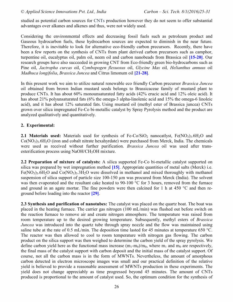
Figures (1) shows the scanning electron microscopy image of the as-grown carbon nanostructures over
Fe-Co bimetallic catalyst, impregnated in silica at 650 °C under the flow of nitrogen by CVD assisted
spray pyrolysis method. SEM image clearly reveals that CNTs grew nicely on the surface of the silica
particles with heterogeneous diameter.
Figure (1): Scanning electron micrographs of as grown MWCNTs at 650 °C.
The morphologies of the carbon nanostructure deposit obtained were characterized by HRTEM. Dense
rope like carbon nanostructure was grown from the surface of the dark catalyst clusters. A closer look
with higher magnification shows the rope like tubular carbon structure with hollow core, confirming the
formation of CNTs [30]. Figures 2 (a-d) shows the HRTEM images of samples synthesized at 650 °C
using methyl ester of Brassica Juncea oil as carbon source over Fe-Co supported on silica. It clearly
seen from HRTEM measurements that well-graphitized MWCNTs grown from catalytic decomposition
of methyl ester of Brassica Juncea oil at 650 °C with heterogeneous diameter of the tube structure
(Figure 2b). The growth of nanotubes with a bigger diameter due to agglomeration of catalyst particles.

© Applied Science Innovations Pvt. Ltd., India Carbon – Sci. Tech. 8/1(2016)25-31
28
This finding agrees with experimental results from several authors. It can be observed from HRTEM
images that the nanotubes formed are of multi-walled type composed of around 20 walls and most
graphene layers grow perpendicularly to the growth axis of the tubes. The average outer diameter of the
nanotube ranges from 15-20 nm and inner diameter is about 8 nm (Figure 2c).
(a)
(b)
(c)
(d)
Figure (2): (a, b, c) HRTEM of as grown MWCNTs at 650 °C; (d) HRTEM image of as-grown
MWCNTs with catalyst particle encapsulated at tip (tip growth mechanism).
4. Raman studies: Figure (3) shows the Raman spectra of as-synthesized MWCNTs at 650 oC has three
characteristics peaks are observed at 1342.24 cm-1
, 1572.57 cm-1
and 2686.71 cm-1
(532 nm)
corresponding to D-peak, G- peak and G’-peak. The G peak corresponds to the tangential stretching
(E2g) mode of the highly oriented pyrolytic graphite and suggests the CNTs to be composed of
crystalline graphitic carbon. The D-peak at 1342.24 cm-1
originates from disorder in the sp2-hybridized
carbon and indicates lattice distortions in the curved graphene sheets, tube ends, etc. On the other hand,
band at 2683 cm–1
called the G’-peak and attributed to the overtone of the D-peak. G’-peak originates
from thicker multi-layer carbon nanotubes. The absence of peak under 300 cm-1
shows the absence of
SWCNTs [31]. The IG/ID ratio found as 1.17. This higher ratio value corresponds to a lower proportion
of sp3-like carbon, originates from disorder in the sp
2-hybridized carbon and indicates good
graphitization in the curved graphene sheets, tubes ends etc [32].

© Applied Science Innovations Pvt. Ltd., India Carbon – Sci. Tech. 8/1(2016)25-31
29
Figure (3): Raman Spectra of as-synthesized MWCNT at 650 oC using spray pyrolysis method.
5. XRD ANALYSIS: The XRD spectrum of as-synthesized MWCNTs was recorded with 2-theta (2θ)
between 10 oC to 80
oC. Figure (4) shows the XRD diffraction pattern of as-synthesized MWCNTs
having three peaks at 26o, 44
o and minor peak at 77
o are identified. At synthesis temperature of about
650 oC, the XRD pattern of MWCNTs was reported to show mainly graphitic reflections at 26
o and 77
o
corresponds to (002) and (112) respectively. Obviously in Figure (4) only two peaks at 26o and 44
o are
prominent. The small peak at 77o suggests presence of Fe3C in the as-synthesized sample. The metal
carbides act as active catalysts in the formation of tubular structure of graphitic carbon [33].
Figure (4): XRD pattern of as-synthesized MWCNTs grown at 650 oC.
6. Conclusions: We accomplished the synthesis of MWCNTs at a temperature of 650 oC using methyl
esters of Brassica Juncea oil on Fe-Co supported on Silica. CNTs morphology and structure were
investigated by SEM, HRTEM, XRD, and Raman spectroscopy. It was found that temperature was
enough to transform hydrocarbon source into carbon nanotubes using plant derived precursor methyl
esters of Brassica Juncea oil with heterogeneous diameter, good quality and yield at this temperature.
Thus we could grow good crystalline MWCNTs at low temperature by spray pyrolysis of methyl ester of
Brassica Juncea without of release of any toxic chemicals.
Acknowledgement: The authors acknowledge the UGC New Delhi for financial support, the Institute
for Environmental and Nanotechnology for technical support and IITM for access to electron
microscopes.

© Applied Science Innovations Pvt. Ltd., India Carbon – Sci. Tech. 8/1(2016)25-31
30
References:
[1] S. Iijima, Nature 354 (1991) 56.
[2] A. Oberlin, M. Endo, T. Koyama, ‘Filamentous growth of carbon through benzene
decomposition’, J. Cryst. Growth 32 (1976) 335 - 349.
[3] P. G. Collins, P. Avouris, Sci. Am. 283/6 (2000) 62 – 69.
[4] A. A. Puretzky, D. B. Geohegan, X. Fan, S. J. Pennycook, Appl. Phys. A 70 (2000) 153 – 160.
[5] M. C. Paladugu, K. Maneesh, P. K. Nair, P. Haridoss, J. Nanosci. Nanotechnol. 5/5 (2005) 747-
752.
[6] R. Brukh, S. Mitra, Chem. Phys. Lett. 424, 1-3 (2006) 126 - 132.
[7] Zhi Yang, Xiaohua Chen, Huagui Nie, Ke Zhang, Wenhua Li, Bin Yi, Longshan Xu, Nanotech.
19, 8 (2008).
[8] Lingyu Piao, Yongdan Li, Jiuling Chen, Liu Chang, Jerry Y.S. Lin, Catalysis Today 76 (2002) 2 -
4.
[9] Sakae Takenakaa, Toshiyuki Iguchia, Eishi Tanabeb, Hideki Matsunea, Masahiro Kishidaa,
Carbon 47/5 (2009) 1251 – 1257.
[10] Ki-Eun Kim, Kang-Jin Kim, Woo Sung Jung, Seung Yong Bae, Jeunghee Park, Junghyun Choi,
Jaebum Choo, Chem Phys Lett. 401 (2005) 4 – 6.
[11] P. Ndungu, Z. G. Godongwana, L. F. Petrik, A. Nechaev, S. Liao, V. Linkov, Microporous and
Mesoporous Materials 1-3 (2008).
[12] Yajun Tian, Zheng Hu, Yong Yang, Xizhang Wang, Xin Chen, Hua Xu, Qiang Wu, Weijie Ji, Yi
Chen, J. Am. Chem. Soc. 126/4 (2004) 1180 - 1183.
[13] Doh C. Lee, Frederic V. Mikulec, Brian A. Korgel, J. Am. Chem. Soc. 126/15 (2004) 4951-4957.
[14] Clarence S. Yaha, Sunny E. Iyuke, Geoffrey S. Simate, Emmanuel I. Unuabonah, Graham
Bathgate, George Matthews, John D. Cluett, J. Mater. Res. 26/5 (2011) 640 - 644.
[15] Mukul Kumar, Yoshinori Ando, Carbon 43 (2005) 533 - 540.
[16] R. A. Afre, T. Soga, T. Jimbo, M. Kumar, Y. Ando, M. Sharon, P. R. Somani, M. Umeno,
Microporous and Mesoporous Materials 96 (2006) 184 – 190.
[17] Rakesh A. Afre, T. Soga and T. Jimbo, Materials Letters 61/17 (2007) 3768 - 3770.
[18] A. B. Suriani, A. A. Azira, S. F. Nik, Roslan Md. Nor, M. Rusop, Materials Letters 63 (2009)
2704 - 2706.
[19] Rajesh Kumar, Radhey Shyam Tiwari, Onkar Nath Srivastava, Nanoscale Res. Lett. 6/1 (2011).
[20] D. E. Kshirsagar, V. Puri, M. Sharon, S. Jaybhaye, R. A. Afre, P. R. Somani, M. Sharon,
Advanced Science Letters 2 (2009) 388 – 390.
[21] S. Karthikeyan, P. Mahalingam, Int. J. Nanotechnol. Appl. 4 (2010) 189.
[22] S. Karthikeyan, P. Mahalingam, Int. J. Green Nanotechnol. Phys. Chem. 2 (2010) 39.
[23] S. Mageshwari, S. Kalaiselvan, P. S. Syed Shabudeen, N. Sivakumar, Karthikeyan, Int. J. Mater.
Sci. Poland 32/4 (2014) 709 - 718.
[24] V. S. Angulakshmi, K. Rajasekar, C. Sathiskumar, S. Karthikeyan, New Carbon Mater. 28 (2013)
284.
[25] V. S. Angulakshmi, C. Sathiskumar, M. Karthik, S. Karthikeyan, J. Environ. Nanotechnol. 2
(2013) 101.
[26] S. Karthikeyan, S. Kalaiselvan, D. Manorangitham, S. Maragathamani, J. Environ. Nanotechnol. 2
(2013) 15.
[27] S. Kalaiselvan, M. Karthik, R. Vladimir, S. Karthikeyan, J. Environ. Nanotechnol. 3 (2014) 92.
[28] S. Mageswari, P. S. Syed Shabudeen, S. Karthikeyan, ‘Optimization of growth temperature of
multi-walled carbon nanotubes synthesized by spray pyrolysis method and application for arsenic
removal’, Carbon – Sci. Tech. 6/3 (2014) 1-1.
[29] S. D. Mhlanga, C. M. Kartick, C. Robin, J. W. Michael, J. C. S. Neil, Afr. J. Chem. 62 (2009) 67.
[30] J. Logeswari, A.Pandurangan and D. Sangeetha, Ind. Eng. Chem. Res. 50/23 (2011) 3347-13354.

© Applied Science Innovations Pvt. Ltd., India Carbon – Sci. Tech. 8/1(2016)25-31
31
[31] M. S. Dresselhaus, G. Dresselhaus, A. Jorio, A. G. Souza Filho, R. Saito, Carbon 40 (2002).
[32] A. S. Patole, S. P. Patole, J.-B. Yoo, J.-H. Ahn, T.-H. Kim, J. Polymer Sci. Part B: Polymer Phy.
47/15 (2009) 1523 - 1529.
[33] Pitamber Mahanandia, Jorg J. Schneider, Martin Engel, Bernd Stuhn, Somanahalli V.
Subramanyam, Karuna Kar Nanda, Beilstein J. Nanotechnol. 2 (2011) 293 - 301.
*****