brooks€¦ · brooks tradition of producing dependable engineered products is vividly evident in...
TRANSCRIPT

B3.5
BROOKSMANUFACTURING CO. TRANSMISSION
X-Braces
BROOKS tradition of producing dependable engineered products is vividly evident in our diverse line of wood X-braces. Our solid engineering commitment and decades of wood structure design and testing provide the experience and knowledge necessary to select the proper bracing to meet both your strength and budget requirements.
A set of wood X-Braces is the most economical method of fully developing the transverse capacity of the H-frame structure. Wood members provide the required tensile and compressive strengths without sacrificing the “BIL” levels associated with wood construction. The wide range of BROOKS X-Brace styles provides the transmission designer an optimum match for the given pole spacing and pole class required for the specific job through 345kV construction. BROOKS Engineering Department will work with you on applications of these standard X-Braces or a custom designed X-Brace to meet your individual needs.
Our ready access to both solid sawn and reliable conventional glued laminated coastal region Douglas fir,
1⁄2”1⁄2”
combined with our flexibility in hardware designs, allows easy selection of BROOKS bracing to match your existing system standards.
X-Braces should be ordered by specifying center to center pole spacings. All X-Brace members are shipped factory assembled with static proof fittings locked securely in place. Unless specified otherwise, all necessary mounting hardware required to install the assembly is included. Typical length mounting bolts have been pre-selected as noted by each style and will be shipped with the braces unless specified differently on the order. Refer to the ordering codes on the next page which explain other variations of ordering available for special applications or component combinations.
BROOKS has many other proven designs in addition to those illustrated. We welcome the opportunity to review your structure requirements or system standards to recommend the best X-Braces for your applications.

B3.5.1
BROOKSMANUFACTURING CO. POLE LINE HARDWARE
X-Brace Ordering Codes For use when ordering by center to center (C/C) pole spacing
For 670, 671, 675, 677, 678, 6050, 6051, 6680, 6685, 6685A, 6695, 6696 & 41005 X-Brace Series
Ordering Information:
)stigiD 5 ro 4 ,3( seireS elytS ecarB )sehcnI dna teeF( gnicapS eloP C/C
X X X X - X X - X - X X X
Additional Code Digits for Variable NM ….. No Mounting Hardware, Includes Center Clamp Assembly
ylbmessA pmalC retneC sseL ,erawdraH gnitnuoM llA ..… CN ylbmessA pmalC retneC ro erawdraH gnitnuoM oN… CMN
...… CP One Piece of X-Brace With Assembled End Fittings Only
Ordering Examples:
6685-15-6 = 1 set of X-Braces for 15’-6” C/C pole spacing, complete with (2) pieces of wood assembled to end .ylbmessa pmalc retnec dna erawdrah gnitnuom lla ,sgnittif
6685-15-6-NM = 1 set of X-Braces for 15’-6” C/C pole spacing, with (2) pieces of wood assembled to end fittings, .erawdrah gnitnuom ssel ,ylno ylbmessa pmalc retnec htiw
6685-15-6-NMC = 1 set of X-Braces for 15’-6” C/C pole spacing, with (2) pieces of wood assembled to end fittings, less .ylbmessa pmalc retnec ssel dna erawdrah gnitnuom
6685-15-6-PC = 1 piece of an X-Brace for 15’-6” C/C pole spacing (one piece of wood assembled to end fittings only, .)ylbmessa pmalc retnec ssel dna erawdrah gnitnuom ssel
When mounting bolts are required in lengths other than those listed as standard for each style of X-Brace, indicate those lengths in a descriptive form along with the order number. As an example: 6685-15-6, mounting bolts 25% - 14”, 50% - 16” and 25% - 18”.
A variety of other ordering options is available which consider MHC of individual brace components as well as concerns for special mounting hardware combinations and bolt length arrangements. BROOKS welcomes the opportunity to assist in recommending the style of brace and confirm the appropriate catalog number which meets your system standards or structure requirements.

B3.5.2
BROOKSMANUFACTURING CO. TRANSMISSION
6680 Series X-Braces Reference pages B3.5.16 to B3.5.18 for strength Single Bolt Connection, Cut Thread. Wood Section - 33⁄8” x 43⁄8”. Fitting thickness - 1⁄4”. Mounting bolt diameters - 7⁄8”. Unless specified otherwise, standard bolt length furnished are 50% - 14” and 50% - 16”.
To estimate shipping weight of the assembly complete with all mounting hardware, multiply C/C pole spacing by 10.2, then add 53 pounds.
Assembly View
Detail View
12" Bolts
716" Bonding Hole
78" Bolt
& Locknut
SCW7-404Square CurvedWasher
316" Washer
Plate
14" Fittings
338"
438"
Specify Pole Spacing
41010-1Center Clamp
Assembly
REA TM110A

B3.5.3
BROOKSMANUFACTURING CO. TRANSMISSION
6685A Series X-Braces Reference pages B3.5.16 to B3.5.18 for strength Single Bolt Connection, Cut Thread. Wood Section - 33⁄8” x 53⁄8”. Fitting thickness - 1⁄4”. Mounting bolt diameters - 7⁄8”. Unless specified otherwise, standard bolt length furnished are 50% - 14” and 50% - 16”.
To estimate shipping weight of the assembly complete with all mounting hardware, multiply C/C pole spacing by 12.5, then add 54pounds.
Assembly View
Detail View
78" Bolt
& Locknut
SCW7-404Square CurvedWasher
Specify Pole Spacing
538"
REA TM110B
41010-2Center Clamp
Assembly
12" Bolts
716" Bonding Hole
316" Washer
Plate
14" Fittings
338"

B3.5.4
BROOKSMANUFACTURING CO. TRANSMISSION
6685 Series X-Braces Reference pages B3.5.16 to B3.5.18 for strength Single Bolt Connection, Cut Thread. Wood Section - 33⁄4” x 53⁄4”. Fitting thickness - 1⁄4”. Mounting bolt diameters - 7⁄8”. Unless specified otherwise, standard bolt length furnished are 50% - 14” and 50% - 16”.
To estimate shipping weight of the assembly complete with all mounting hardware, multiply C/C pole spacing by 15.1, then add 60 pounds.
Assembly View
Detail View
12" Bolts
716" Bonding Hole
78" Bolt
& Locknut
SCW7-404Square CurvedWasher
316" Washer
Plate
Specify Pole Spacing
41010-4Center Clamp
Assembly
334"
534"
14" Fittings
REA TM110B

B3.5.5
BROOKSMANUFACTURING CO. TRANSMISSION
6050 Series X-Braces Reference pages B3.5.16 to B3.5.18 for strength Single Bolt Connection, Cut Thread. Wood Section - 33⁄4” x 53⁄4”. Fitting thickness - 3⁄8”. Mounting bolt diameters - 7⁄8”. Unless specified otherwise, standard bolt length furnished are 50% - 14” and 50% - 16”.
To estimate shipping weight of the assembly complete with all mounting hardware, multiply C/C pole spacing by 15.1, then add 76 pounds.
Assembly View
Detail View
58" Bolts
716" Bonding Hole
78" Bolt
& Locknut
SCW7-404Square CurvedWasher
316" Washer
Plate
Specify Pole Spacing
41010-4Center Clamp
Assembly
38" Fittings
334"
534""

B3.5.6
BROOKSMANUFACTURING CO. TRANSMISSION
6051 Series X-Braces Reference pages B3.5.16 to B3.5.18 for strength Single Bolt Connection, Cut Thread. Wood Section - 33⁄4” x 53⁄4”. Fitting thickness - 3⁄8”. Mounting bolt diameters - 7⁄8”. Unless specified otherwise, standard bolt length furnished are 50% - 14” and 50% - 16”.
To estimate shipping weight of the assembly complete with all mounting hardware, multiply C/C pole spacing by 15.1, then add 96 pounds.
Assembly View
Detail View
12" Bolts
716" Bonding Hole
78" Bolt
& Locknut
SCW7-404Square CurvedWasher
316" Washer
Plate
Specify Pole Spacing
41010-4Center Clamp
Assembly
38" Fittings
334"
534"
B3.5.7
BROOKSMANUFACTURING CO. TRANSMISSION
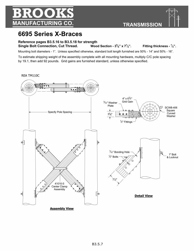
6695 Series X-Braces Reference pages B3.5.16 to B3.5.18 for strength Single Bolt Connection, Cut Thread. Wood Section - 35⁄8” x 71⁄2”. Fitting thickness - 1⁄4”. Mounting bolt diameters - 1”. Unless specified otherwise, standard bolt length furnished are 50% - 14” and 50% - 16”.
To estimate shipping weight of the assembly complete with all mounting hardware, multiply C/C pole spacing by 19.1, then add 92 pounds. Grid gains are furnished standard, unless otherwise specified.
Detail View
12" Bolts
716" Bonding Hole
1" Bolt& Locknut
SCW8-406Square CurvedWasher
316" Washer
Plate
Specify Pole Spacing
14" Fittings
4" x 634"
Grid Gain
358"
712"
REA TM110C
Assembly View
41010-5Center Clamp
Assembly
B3.5.8
BROOKSMANUFACTURING CO. TRANSMISSION
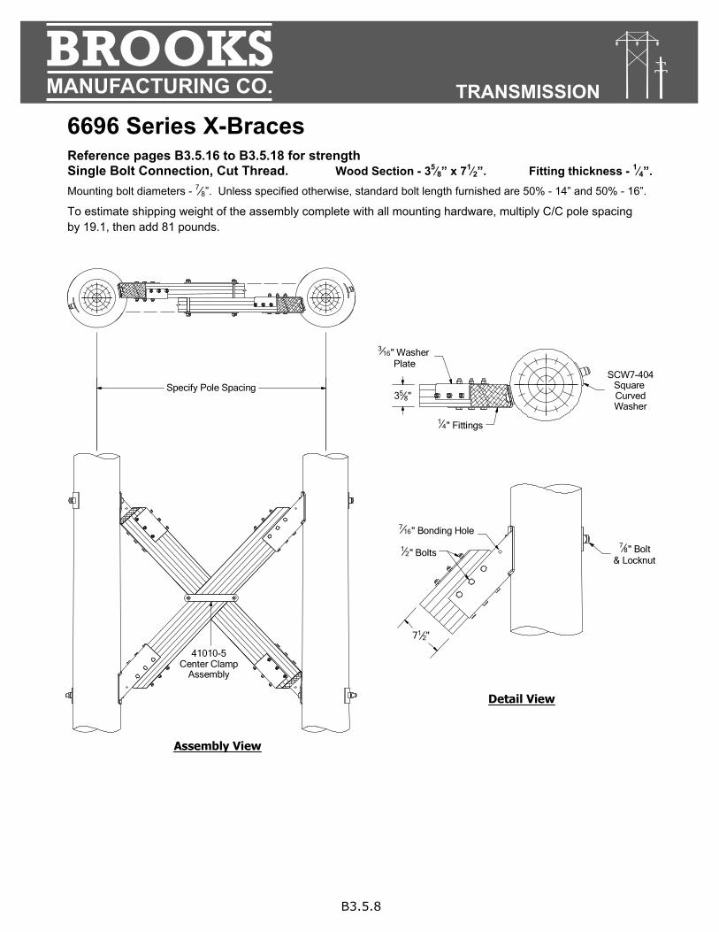
6696 Series X-Braces Reference pages B3.5.16 to B3.5.18 for strength Single Bolt Connection, Cut Thread. Wood Section - 35⁄8” x 71⁄2”. Fitting thickness - 1⁄4”. Mounting bolt diameters - 7⁄8”. Unless specified otherwise, standard bolt length furnished are 50% - 14” and 50% - 16”.
To estimate shipping weight of the assembly complete with all mounting hardware, multiply C/C pole spacing by 19.1, then add 81 pounds.
Assembly View
Detail View
12" Bolts
716" Bonding Hole
78" Bolt
& Locknut
316" Washer
Plate
Specify Pole Spacing
41010-5Center Clamp
Assembly
71
2"
358"
14" Fittings
SCW7-404Square CurvedWasher

B3.5.9
BROOKSMANUFACTURING CO. TRANSMISSION
41005 Series X-Braces Reference pages B3.5.16 to B3.5.18 for strength Single Bolt Connection, Cut Thread. Wood Section - 35⁄8 ” x 81⁄2”. Fitting thickness - 1⁄4”. Mounting bolt diameters - 7⁄8”. Unless specified otherwise, standard bolt length furnished are 50% - 14” and 50% - 16”.
To estimate shipping weight of the assembly complete with all mounting hardware, multiply C/C pole spacing by 22.2, then add 137 pounds.
Detail View
12" Bolts
78" Bolt
& Locknut
41005-3Pole
Washer
41010-9Center Clamp
Assembly
31116"
812"
14" Fittings
Specify Pole Spacing
Assembly View

B3.5.10
BROOKSMANUFACTURING CO. TRANSMISSION
670 Series X-Braces Reference pages B3.5.16 to B3.5.18 for strength Pin Connection. Fitting thickness - Straight 3⁄8”, Bent 1⁄4”. Cut thread mounting bolt diameters - 7⁄8”. Unless specified otherwise, standard bolt length furnished are 50% - 16” and 50% - 18”.
Unless specified otherwise, assembly is furnished complete with standard mounting hardware including mounting bolts, tees, pin bolts, washers, nuts and locknuts. To include grid gains, add suffix “-G” to part number when
To estimate complete assembly shipping weight:
Catalog Number
Wood Size Center Clamp Assembly No.
Approx. Shipping Wt. Lbs. D W
670A 33⁄4” x 53⁄4” 41010H-4 14.9 plus 134 lbs. = _______________
670B 51⁄8” x 6” 41010H-11 20.5 plus 138 lbs. = _______________
♦ 670C 45⁄8” x 55⁄8” 41010H-12 18.0 plus 135 lbs. = _______________
670D 41⁄2” x 51⁄2” 41010H-16 17.5 plus 135 lbs. = _______________
♦ REA TM-110D (45⁄8” x 55⁄8”)
C/C Pole Spacing Multiplied By
Detail View
Assembly View
58" Bolts
78" Bolt
& Locknut
SCW7-406Square CurvedWasher
38" Flat Fitting
41010H SeriesCenter Clamp
Assembly
Specify Pole Spacing
12" Washer Head Bolt
& Lip Washer
14" Bent Fitting
W
D
412" x 9" Grid Gain
Dead End Tee
1" Bolt & Locknut
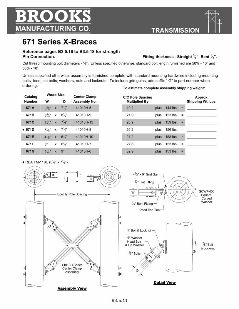
ordering.
B3.5.11
BROOKSMANUFACTURING CO. TRANSMISSION
671 Series X-Braces Reference pages B3.5.16 to B3.5.18 for strength Pin Connection. Fitting thickness - Straight 3⁄8”, Bent 1⁄4”. Cut thread mounting bolt diameters - 7⁄8”. Unless specified otherwise, standard bolt length furnished are 50% - 16” and 50% - 18”.
Unless specified otherwise, assembly is furnished complete with standard mounting hardware including mounting bolts, tees, pin bolts, washers, nuts and locknuts. To include grid gains, add suffix “-G” to part number when
To estimate complete assembly shipping weight:
Catalog Number
Wood Size Center Clamp Assembly No.
Approx. Shipping Wt. Lbs. D W
671A 35⁄8” x 71⁄2” 41010H-5 19.2 plus 144 lbs. = _______________
671B 35⁄8” x 81⁄2” 41010H-9 21.9 plus 153 lbs. = _______________
671C 51⁄2” x 71⁄2” 41010H-13 28.9 plus 159 lbs. = _______________
♦ 671D 51⁄8” x 71⁄2” 41010H-8 26.2 plus 156 lbs. = _______________
671E 41⁄2” x 63⁄4” 41010H-10 21.2 plus 153 lbs. = _______________
671F 6” x 63⁄4” 41010H-7 27.6 plus 153 lbs. = _______________
671G 51⁄8” x 9” 41010H-6 32.9 plus 153 lbs. = _______________ ♦ REA TM-110E (51⁄8” x 71⁄2”)
C/C Pole Spacing Multiplied By
Detail View
Assembly View
58" Bolts
78" Bolt
& Locknut
SCW7-406Square CurvedWasher
38" Flat Fitting
41010H SeriesCenter Clamp
Assembly
Specify Pole Spacing
12" Washer Head Bolt
& Lip Washer
14" Bent Fitting
W
D
412" x 9" Grid Gain
Dead End Tee
1" Bolt & Locknut
ordering.

B3.5.12
BROOKSMANUFACTURING CO. TRANSMISSION
675 Series X-Braces Reference pages B3.5.16 to B3.5.18 for strength Wrap Around Two Bolt Connection, Cut Thread. Fitting thickness - 3⁄8”. Mounting bolt diameters - 7⁄8”. Unless specified otherwise, standard bolt length furnished are 50% - 16” and 50% - 18”.
To estimate complete assembly shipping weight:
Catalog Number
Wood Size Center Clamp Assembly No.
Approx. Shipping Wt. Lbs. D W
675 51⁄8” x 71⁄2” 41010H-8 26.5 plus 173 lbs. = ________________
675A 51⁄2” x 71⁄2” 41010H-13 29.4 plus 174 lbs. = ________________
675B 51⁄8” x 6” 41010H-11 22.2 plus 166 lbs. = ________________
675C 45⁄8” x 55⁄8” 41010H-12 18.8 plus 176 lbs. = ________________
C/C Pole Spacing Multiplied By
Detail View
58" Bolts 7
8" Bolt& Locknut
SCW7-406Square Curved
Washer
38" Fittings
41010H SeriesCenter Clamp
Assembly
Specify Pole SpacingW
D
Assembly View

B3.5.13
BROOKSMANUFACTURING CO. TRANSMISSION
677 Series X-Braces Reference pages B3.5.16 to B3.5.18 for strength Pin Connection. Fitting thickness - 3⁄8”. Cut thread mounting bolt diameters - 7⁄8”. Standard bolt length furnished are 50% - 16” and 50% - 18”.
Unless specified otherwise, assembly is furnished complete with all mounting hardware including tees, grid gains, pin bolts, washers, nuts and locknuts.
To estimate complete assembly shipping weight:
Catalog Number
Wood Size Center Clamp Assembly No.
Approx. Shipping Wt. Lbs. D W
677A 51⁄8” x 6” 41010H-11 20.8 plus 198 lbs. = _______________
677B 51⁄8” x 71⁄2” 41010H-8 26.1 plus 200 lbs. = _______________
677C 6” x 63⁄4” 41010H-7 27.5 plus 198 lbs. = _______________
677D 63⁄4” x 71⁄2” 41010H-17 34.1 plus 203 lbs. = _______________
C/C Pole Spacing Multiplied By
Detail View
Assembly View
58" Bolts
78" Bolt
& Locknut
SCW7-406Square CurvedWasher
38" Flat Fitting
41010H SeriesCenter Clamp
Assembly
Specify Pole Spacing
38" Bent Fitting
412" x 9" Grid Gain
38" x 2" U-Strap
Dead End Tee
1" Bolt & Locknut
34" Bolts
W
D

B3.5.14
BROOKSMANUFACTURING CO. TRANSMISSION
678 Series X-Braces Reference pages B3.5.16 to B3.5.18 for strength Pin Connection. Fitting thickness - 3⁄8”. Cut thread mounting bolt diameters - 1”. Standard bolt length furnished are 50% - 18” and 50% - 20”.
Unless specified otherwise, assembly is furnished complete with all mounting hardware including tees, grid gains, pin bolts, washers, nuts and locknuts.
To estimate complete assembly shipping weight:
Wood Size Center Clamp Assembly No.
C/C Pole Spacing Multiplied By
Approx. Shipping Wt. Lbs. D W
678A 51⁄8” x 71⁄2” 41010H-8 27.5 plus 289 lbs. = _______________
678B 6” x 63⁄4” 41010H-7 27.6 plus 289 lbs. = _______________
678C 63⁄4” x 71⁄2” 41010H-17 33.2 plus 293 lbs. = _______________
Catalog Number
Detail View
Assembly View
58" Bolts
1” Bolt& Locknut
SCW8-406Square CurvedWasher
38" Flat Fitting
41010H SeriesCenter Clamp
Assembly
Specify Pole Spacing3
8" Bent Fitting3
8" x 2" U-Strap
Dead End Tee
" Bolt & Locknut
34" Bolts
W
D
4" x 634" Grid Gain
114
678D 5 x 71⁄2 29.8 plus 285 lbs. = _______________
1⁄2” 41010H-13

B3.5.15
BROOKSMANUFACTURING CO. TRANSMISSION
X-Brace Center Clamps Center clamps are furnished as sets of 2 straps and 2 shoulder rods, shipped complete with nuts and locknuts. Center clamps function equally well when installed in either the vertical or horizontal plane. However, by mounting the center clamp straps in a horizontal plane, risk of damaging fallen conductor at the center phase is reduced.
41010 Series Center Clamps
41010H Series Center Clamps
The 41010H Series Heavy Center Clamps have 1⁄4” x 3” straps and are used with BROOKS series 670, 671, 675, 677 and 678 Series X-Braces where heavier loading is imposed.
Catalog Number
Rod Shoulder Width “X”
MHC Strap“Y”
Approx. Wt. Lbs.
41010-1 63⁄4” 75⁄8” 33⁄8” x 43⁄8” 3.7
41010-2 63⁄4” 9” 33⁄8” x 53⁄8” 4.1
41010-3 73⁄8” 131⁄2” 311⁄16” x 81⁄2” 5.1
41010-4 71⁄2” 95⁄8” 33⁄4” x 53⁄4” 3.9
41010-5 71⁄4” 12” 35⁄8” x 71⁄2” 4.9
41010-6 101⁄4” 141⁄4” 51⁄8” x 9” 5.7
41010-7 12” 11” 6” x 63⁄4” 5.9
41010-8 101⁄4” 12” 51⁄8” x 71⁄2” 5.3
41010-9 71⁄4” 131⁄2” 35⁄8” x 81⁄2” 5.1
41010-10 9” 11” 41⁄2” x 63⁄4” 4.9
41010-11 101⁄4” 97⁄8” 51⁄8” x 6” 4.8
41010-12 91⁄4” 93⁄8” 45⁄8” x 55⁄8” 4.4
41010-13 11” 12” 55⁄8” x 71⁄2” 5.2
41010-14 71⁄2” 12” 33⁄4” x 71⁄2” 4.7
Wood Section
Catalog Number
Rod Shoulder Width “X”
MHC Strap“Y”
Approx. Wt. Lbs.
41010H-4 71⁄2” 95⁄8” 33⁄4” x 53⁄4” 6.2
41010H-5 71⁄4” 12” 35⁄8” x 71⁄2” 7.5
41010H-6 101⁄4” 141⁄4” 51⁄8” x 9” 8.8
41010H-7 12” 11” 6” x 63⁄4” 8.0
41010H-8 101⁄4” 12” 51⁄8” x 71⁄2” 7.8
41010H-9 71⁄4” 131⁄2” 35⁄8” x 81⁄2” 8.1
41010H-10 9” 11” 41⁄2” x 63⁄4” 7.2
41010H-11 101⁄4” 97⁄8” 51⁄8” x 6” 7.8
41010H-12 91⁄4” 93⁄8” 45⁄8” x 55⁄8” 6.5
41010H-13 11” 12” 55⁄8” x 71⁄2” 7.8
41010H-15 91⁄2” 95⁄8” 43⁄4” x 53⁄4” 6.7
41010H-16 9” 93⁄8” 41⁄2” x 51⁄2” 6.5
41010H-17 131⁄2” 12” 63⁄4” x 71⁄2” 8.4
Wood Section
Y
X1
2" Rod, Nut& Locknut
14" x 13
4" Stock
Y
X1
2" Rod, Nut& Locknut
14" x 3" Stock

B3.5.16
BROOKSMANUFACTURING CO. POLE LINE HARDWARE
X-Brace Strength X-Brace Axial Forces X-braces are effective framing components for H-frame structures. Brace axial forces can be either tensile or compressive, and are a function of the specific structure configuration and the total imposed wind and gravity loads. Factors which affect X-brace axial forces include pole spacing, structure height, pole species and class, the quantity and position of the braces, stiffness of the upper H-frame truss, and class of soil.
Strength & Stiffness Considerations Several limiting factors must be balanced when selecting the most economical X-brace design for a given set of structure and loading parameters. Limits for these factors have been determined for a wide variety of connection designs and wood sizes, using data developed by the testing of components and full scale structures. Final brace selection is controlled by the most restrictive of these factors.
Axial Tension - End fittings must distribute
the axial load into the wood member, controlling wood bearing stresses and fitting deformation.
Bearing On The Pole - Bearing stresses
parallel or perpendicular to the grain in the wood pole are species sensitive, and must be limited under the fittings, washers, and bolts.
Compressive Buckling - The accepted industry method
for determining the ultimate theoretical compressive strength of a wood X-brace, either solid or laminated, is an adjusted Euler buckling equation. It is dependent on the slenderness ratio and material modulus of elasticity, and is affected by end fitting relative fixity and load eccentricity.
Vibration - Extremely slender compression members are
subject to wind induced vibration. This can cause fatigue, and should be avoided.

B3.5.17
BROOKSMANUFACTURING CO. TRANSMISSION
X-Brace Strength continued.. The curved portions of the nomograph on page B3.5.18 indicate relative X-Brace member compressive buckling strength for various wood sizes and pole spacing. Parameters selected for the curve plot include braces at 45 degrees, a conservative modulus of elasticity, a consistent adjustment factor for the Euler buckling equation, and a slenderness ratio maximum of 50. The curve position will vary with these parameters according to your specific application.
The braces are also limited by the combination of axial tension in the connection and bearing on the pole. The various X-Brace Series connection designs have been classed as Types A through G as shown above. The member load limit for each connection type is indicated by a horizontal line on the page B3.5.18 nomograph.
Type A 7⁄8” Bolt, 1⁄4” Fitting
Type D Wrap Around
Type A1 7⁄8” Bolt, 3⁄8” Fitting
Type E Pinned
Type B 1” Bolt, 1⁄ ” Fitting
Type F Heavy Pinned
Type C Double 7⁄8” Bolt, 1⁄4” Fitting
Type G Extra Heavy Pinned
Series 66806685A 6685 6696
Series 6050 6051
Series 6695
Series41005
Series 675
Series 670 671
Series 677
Series 678
4

B3.5.18
BROOKSMANUFACTURING CO. TRANSMISSION
X-Brace Member Axial Strength Limitations
Example for Preliminary Selection of X-Braces Given: Pole Spacing = 19’-6” and X-Brace load = 29 kips 1. Enter pole spacing axis and project a vertical line up from 19.5 feet. 2. Enter X-brace ultimate load capacity axis and project a horizontal line right from 29 kips. 3. The intersection of the projected vertical and horizontal lines indicates that the minimum required
section size is 45⁄8” x 55⁄8”. 4. This intersection point also indicates that connection types D and E have a connection capacity in excess of 29 kips. 5. Refer to page B3.5.17. Initial selections would be 670C (page B3.5.10) or 675C (page B3.5.12).
Contact BROOKS Engineering Department for assistance in selecting the brace which will best serve your application.
6 3⁄4 ” x 7 1⁄2 ”
6” x 6 3⁄4”5 1⁄2” x 7 1⁄2 ”5 1⁄8” x 9”5 1⁄8” x 7 1⁄2”
4 3⁄4” x 5 3⁄4”4 5⁄8” x 5 5⁄8”
4 1⁄2” x 5 1⁄2”
3 3⁄4” x 5 3⁄4”
3 5⁄8” x 7 1⁄2”
3 3⁄8” x 5 3⁄8”3 3⁄8” x 4 3⁄8”
5 1⁄8” x 6”
A B
A1
C
E D E
F
G
0 10 12 14 16 18 20 22 24 26 28 30 32 34
60
50
40
30
20
10 0
X-Br
ace
Mem
ber,
Ulti
mat
e Lo
ad C
apac
ity (
kips
)
Pole Spacing C/C (Feet)
Denotes Connection Type (See Page B2.5.17)
3 5⁄8” x 8 1⁄2”