-c installation electronic vessel control d9, d12, d16 ec poster … · evcec-c calibration and...
TRANSCRIPT

Installation Electronic Vessel Control D9, D12, D16EVCEC-C
Components and cablesControlsSingle engine control- Aluminum- Stainless steel
Twin engine control- Aluminum- Stainless steel
PCUPower train Control Unit180x160x65 mm (7.1x6.3x2.6 in.)
HCUHelm station Control Unit180x160x65 mm(7.1x6.3x2.6 in.) 1B), 2B),
EVC system displayDisplay incl. cable 1.5 m (5 ft)
Buzzer (optional)
SenderFuel level sender 3–180 ohmFuel level sender 240–30 ohmWater level sender 3–180 ohm
Rudder angle sensor 3–180 ohm
InstrumentsInstruments can be ordered withblack or white dial.
Rings and nuts are not includedOrdered separately.
EVC system tachometer
Diameter 85 mm (3.35 in.)110 mm (4.33 in.)
0–4000 rpm
Speedometer
Diameter 85 mm (3.35 in.)110 mm (4.33 in.)
0–40 kn, 0–23 mph0–60 kn, 0–69 mph
Alarm instrument (optional)
Diameter 52 mm (2.05 in.)
Coolant temp
Diameter 52 mm (2.05 in.)C°, F°
Volt meter
Diameter 52 mm (2.05 in.)12 V, 24 V
Fuel level
Diameter 52 mm (2.05 in.)
Engine oil pressure
Diameter 52 mm (2.05 in.)bar, psi
Turbo pressure
Diameter 52 mm (2.05 in.)bar, psi
Rudder indicator
Diameter 52 mm (2.05 in.)
Fresh water level
Diameter 52 mm (2.05 in.)
Front ring kit (nut)
Diameter 52 mm (2.05 in.)Black/Chrome
Diameter 85 mm (3.25 in.)Black/Chrome
Front ring kit (clamp)
Diameter 52 mm (2.05 in.)Black/Chrome
Diameter 85 mm (3.25 in.)Black/Chrome
EVC kitsSingle engine installation
1A) Main helm station, kit1B) One additional stn, HCU-kit
Two additional stn, HCU-kitThree additional stn, HCU-kit
1C) Additional station, EVC-kit
Twin engine installation
2A) Main helm station, kit2B) One additional stn, HCU-kit
Two additional stn, HCU-kitThree additional stn, HCU-kit
2C) Additional station, EVC-kit
3) Included in engine specification
CablesPos. Feet Meter Part no.
1. Engine–PCU cable,
10 3.0 3808579 3)
16 5.0 3808580
1a. Transmission cable ZF
10 3.0 3808581 3)
1b. Transmission cable MG
10 3.0 3819944 3)
2. Standard EVC bus cablePCU–HCU, 6 pin*
16 5.0 87478923 7.0 88955030 9.0 88955136 11.0 88955242 13.0 889553
*) One cable per engine has to be ordered.
3. Y-connector,EVC bus cable – secondary helmstation, 6-pin
1.6 0.5 3588972 1B), 2C)
4. Y-split multilinkTachometer, EVC system display,syncronization, multisensor,NMEA interface, 6-pin
1.6 0.5 3588206 2A), 2B)
5. Display cable, 6/12-pin
3 1.0 3588207*
*) Incl. in display kit 3884818
6. Multilink/Tachometer andsyncronization cable, 6-pin
5 1.5 3886666 2A), 2C)
7. Control lever cable, 6-pin
5 1.5 8746761A),1C),2A),2C)
8. Key switch and relay cable, 6-pin
3 1.0 888004 1A), 2A)
8a. Relay cable, start-stopcontrol panel, 2/6-pin
3 1.0 881786
9. Y-connector, 12-pin and 8-pin,4–20 mA interface output
0.7/70. 2/2.0 3884709
10. Instruments, panelsand auxiliary cable (optional)
5 1.5 38088521A), 1B), 2A), 2B)
11. Extension cables, 6-pin
EVC bus cableEVC control panelMultilink connectionsHCU–Start/stop control panelHCU–Key switch cableSync. cableEVC system display, multisensorNMEA interface 0183 and 2000
Feet Meter Part no.5 1.5 388941010 3.0 384273316 5.0 384273423 7.0 384273530 9.0 384273636 11.0 3842737
12. Extension cable, 3-pin
Instruments
Feet Meter
3 1.0 87475910 3.0 3807043
Start/stop controlpanel, secondary stationSingle installation 1C)
Twin installation 2C)
MultisensorHull mountedTransom mounted
NMEA 0183 interfaceNMEA 2000 interfaceIncl. cables 0.5 m (1.4 ft.)
4–20 mA interface, input4–20 mA interface, outputIncl. cables
Aux. dimmer unit (ADU)Incl. cables 0.5 m (1.4 ft.)
Relay for external accessories12V, 24V
Key switch, main stationKit, one key switch 1A)
Kit, two key switches 2A)
EVC control panelSingle installation kit 1A), 1C)
Twin installation kit 2A), 2C)
Connectordimensions:3-pin
H = 18 mm (0.71 in.)W = 26 mm (1.02 in.)D = 26 mm (1.02 in.)
6-pin
H = 21 mm (0.82 in.)W = 23 mm (0.88 in.)D = 32 mm (1.26 in.)
12-pin
H = 23 mm (0.88 in.)W = 41 mm (1.62 in.)D = 48 mm (1.90 in.)
W
HD
H
W
D
H
W
D
DMount and connect theEVC control panel
Single engineinstallation
Panels can alsobe flush-mounted.See Installationinstructions.
Dash board holediameter: 52 mm (2.05”)
Twin engineinstallation
Greenmarkingstarboard
Redmarkingport
To X3 on HCU,ext. cable, (11) To X3 on port HCU,
ext. cable, (11)
To X3 on starboardHCU, ext. cable, (11)
PCU/HCU configurationSee labels on units
HCU
PCU
MULTILINKDATALINK AUXKEY
Yel-lowPinkGray Blue
CONTROLS NOT USED
X4 X7 X2 X3 X5 X8
Green Pink
DATALINK ENGINE
X2 X3
Mount PCU and HCU.Connect and clamp cablesB
Mount PCU/HCU withthree screws and plasticbushings
NOTE! Fit strainreliefs on all cables
Chassis no. on PCU/HCU and on engineshall be the same
To X4on HCU
Mount and connect key switchalt. start/stop control panelE
Extension cable (11)alt. relay cable (8a).To X4 on HCU
To X4 on HCU,ext. cable (11)
KEY
Dash board holediameters:
Key switch: 33 mm (1.30”)Panel: 52 mm (2.05”)
Relayexternal accesso-ries
12–25 mm(0.5–1.00”)
2.5–12 mm(0.1–0.5”)
Max. 2.5 mm(0.1”)
Instruments canalso be flush-mounted.See Installationinstructions
Mount tachometer andother instrumentsF
Dash boardhole diameters
Instruments: 110 mm (4.33”)85 mm (3.35”)52 mm (2.05”)
Instruments,flush mounted: 105 mm (4.13”)
83 mm (3.27”)49 mm (1.93”)
Max. recommended CC measurementexcl. extension cable,all instruments: 220 mm (8.6”)
CC
Connect EVC system tachometerConnect instruments in seriesG
Plug
To 6-pinconn. on
tachometer
EVC systemtachometer
To X5 on HCU orMULTILINKBREAKOUT onY-split cable (4)
Multilink/synchronizationcable (6)
Multilink/tachometerand sync.cable (6)
To X5 on HCU orMULTILINKBREAKOUT onY-split cable (4)
To instruments.
Cable included intachometer kit, length200 mm (0.7 ft)
Instruments
EVC systemtachometer
Mount and connectEVC system displayH
DISPLAYCONN.
Use template whenmaking hole in dashboard.
Dash board holediameters:
Drill holes: 4.5 mm (0.17”)Rear side: 65 mm (2.52”)
Display can alsobe flush-mounted.See Installationinstructions
To Y-split MULTILINKBREAKOUT or X5 HCU
PCU
HCU
ADU
Y-connector (3).Must be connectedto HCU or PCU
NOTE! Securecables withclamps.
HCU
Keyswitch
To secondaryhelm station
Rudderanglesensor
Relay forexternalaccessories
Instruments
Fuellevelsender
D9-engine
Fresh waterlevel sender
Multi-sensor
Single installation
NMEAinterface
EVCsystemdisplay
EVCcontrolpanel
EVC systemtachometer
4
11
8
11
4
Diagnosisconnection, 6-pin(VODIA)
Twin installationMain and secondary helm station
IMPORTANT! Never cut or modifiy the Volvo PentaEVC cable harnesses. For extra power supply use theVolvo Penta relay for external accessories.
Y-split multilink
MULTILINKBREAKOUT
MULTILINK
NOTE! Do not connect another Y-split to the MULTILINKBREAKOUT. If more than one Y-split is needed connectthem in chain, MULTILINK to MULTILINK.
HCU
HCU
PCU
NOTE! This end on Y-connector must be installed directly,without extension, to the PCU or HCU
Y-connector
Y-connector
Part no.
Colour coding of cables:Starboard – greenPort – red
Cables and color coding
PCU/HCU identification
ENGINE CHASSIS ID.
VP 000000
ENGINE SERIAL NO.
0000000000
IMPORTANT! Thechassis no. on the PCU/HCU must correspondwith the engine chassisno.
Starboard,right-handrotation
Port,left-handrotation
Standard–left handrotation:Connector PRIMARYto solenoid PConnector SECONDARYto solenoid S
Twin installation:
Propellers seenfrom astern
Reverse gearTwin installations: Check propellerrotation. Shift cable connectors on gearshift solenoids.Port engine: Left hand rotationStarboard engine: Right hand rotation
A
Figures show cables connected for standardleft-hand rotation in forward gear.
SECONDARYS
PRIMARYP PRIMARY
P
OIL TEMP/PRESSURE
SECONDARYS
ZF280/ZF286/ZF305/ZF311/ZF325
MG5065/MG5075/MG5114
TROLLING
REV PIC-UP(D9)
OIL TEMP/PRESSURE
REV PIC-UP(D12, not D16)
TROLLING(D12, not D16)
MG5145/MG5170To X7 on HCU
NOTE! No extensioncables allowed
Connect “THROTTLE POT”and “NEUTRAL SWITCH” tocontrol
CGEAR POTPlease refer toInstallataion EVCEC-CElectronic VesselControl D4, D6, D9,D12, D16.
THROTTLE POT
To X7 on HCU, port
NOTE! No extensioncables allowed
THROTTLE POT
NEUTRALSWITCH
NEUTRALSWITCH
To X7 on HCU, stb.
NOTE! No extensioncables allowed
GEAR POT(not used)GEAR POT
(not used)
THROTTLE POTNEUTRALSWITCH
GEAR POT(not used)
5
4
5
4
11
7
7 7
7 7
3
3 3
Instruments Instruments
ADU
InstrumentsInstruments
EVCsystemdisplay
EVC systemtachometer
EVC systemtachometer
EVC systemtachometer
EVC systemtachometer
EVCsystemdisplay
Relay forexternalaccessories
Relay forexternalaccessories
Keyswitch
EVC controlpanel
EVC controlpanel
Start/Stopcontrol panel
Fuellevelsender
Fresh waterlevel sender
Fuellevelsender
Fresh waterlevel sender
Diagnosisconnection(VODIA)
Multi-sensor
NMEAinterface
ADU
HCU HCU
HCUHCU
Controls
Controls
PCU PCU
Controls
4 4
4 4 4 4 411
11
6
6 6
6 6
6
6
5
11 11
11
2
2 2
1
11
Diagnosisconnection(VODIA)
Ruddersensor
8
8
8a11
11 11
12
1212
12 12
1a 1a
1b 1b
To instruments.
Cable included intachometer kit, length200 mm (0.7 ft)
Ruddersensor
(not used)
X2 Green Data-link – EVC bus cable
X3 Pink Engine and transmission
X2 Green Data-link – EVC bus cable
X3 Pink Auxiliary bus – EVC control panel
X4 Grey Key switch alt. start/stop panel
X5 Yellow Multilink – Tachometer/instruments,engine synchronization, EVC systemdisplay, NMEA-interface, multisensor
X7 Blue Controls
X8 — Not used, plugged
Green
5
EVCEC-C Calibration and settings D9, D12, D16
7745
748
09-
2007
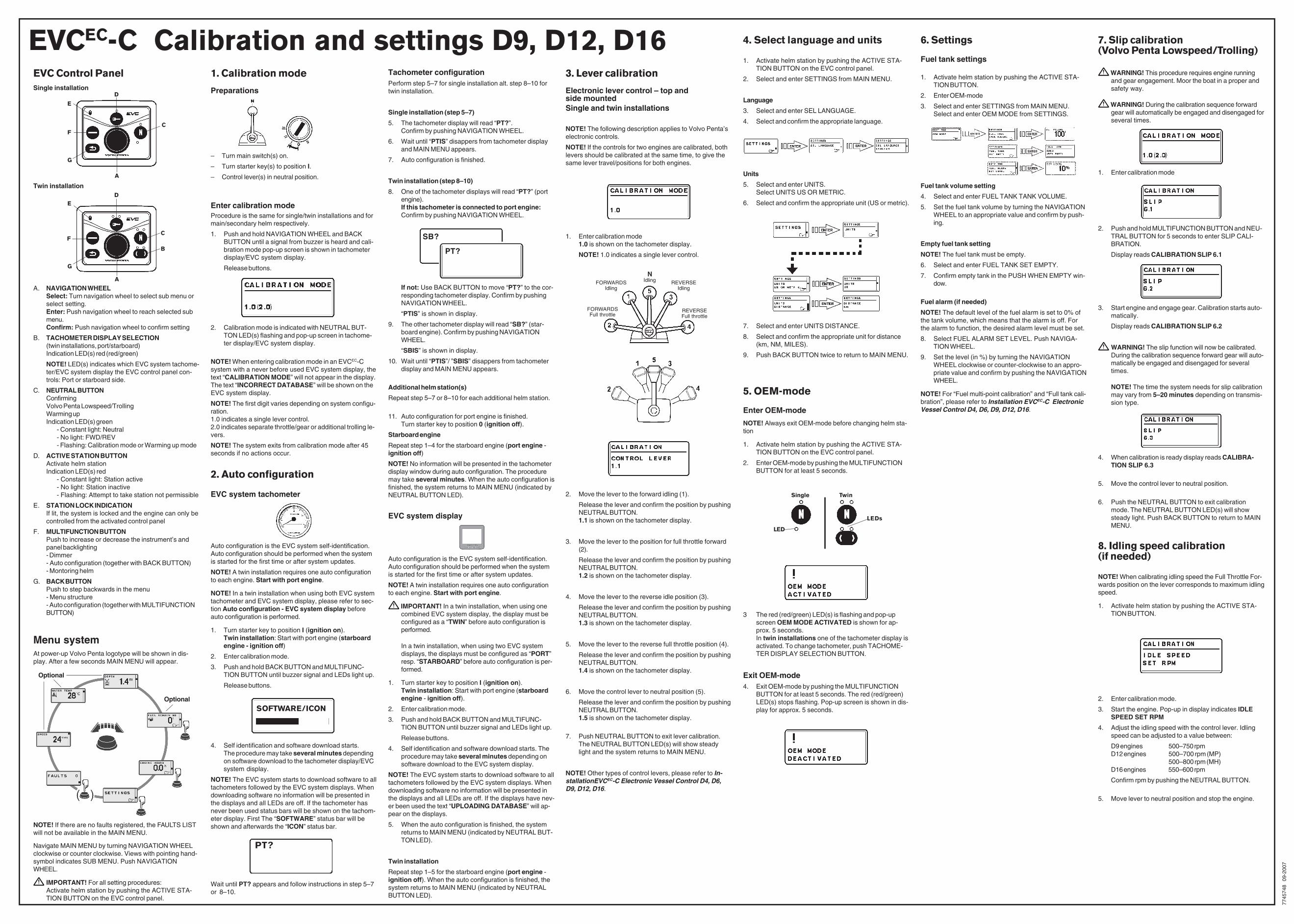
7. Slip calibration(Volvo Penta Lowspeed/Trolling)
WARNING! This procedure requires engine runningand gear engagement. Moor the boat in a proper andsafety way.
WARNING! During the calibration sequence forwardgear will automatically be engaged and disengaged forseveral times.
1. Enter calibration mode
3. Lever calibration
Electronic lever control – top andside mountedSingle and twin installations
NOTE! The following description applies to Volvo Penta’selectronic controls.
NOTE! If the controls for two engines are calibrated, bothlevers should be calibrated at the same time, to give thesame lever travel/positions for both engines.
1. Enter calibration mode1.0 is shown on the tachometer display.
NOTE! 1.0 indicates a single lever control.
2. Move the lever to the forward idling (1).
Release the lever and confirm the position by pushingNEUTRAL BUTTON.1.1 is shown on the tachometer display.
3. Move the lever to the position for full throttle forward(2).
Release the lever and confirm the position by pushingNEUTRAL BUTTON.1.2 is shown on the tachometer display.
4. Move the lever to the reverse idle position (3).
Release the lever and confirm the position by pushingNEUTRAL BUTTON.1.3 is shown on the tachometer display.
5. Move the lever to the reverse full throttle position (4).
Release the lever and confirm the position by pushingNEUTRAL BUTTON.1.4 is shown on the tachometer display.
6. Move the control lever to neutral position (5).
Release the lever and confirm the position by pushingNEUTRAL BUTTON.1.5 is shown on the tachometer display.
7. Push NEUTRAL BUTTON to exit lever calibration.The NEUTRAL BUTTON LED(s) will show steadylight and the system returns to MAIN MENU.
NOTE! Other types of control levers, please refer to In-stallationEVCEC-C Electronic Vessel Control D4, D6,D9, D12, D16.
NIdlingFORWARDS
IdlingREVERSE
Idling
REVERSEFull throttle
FORWARDSFull throttle
2. Push and hold MULTIFUNCTION BUTTON and NEU-TRAL BUTTON for 5 seconds to enter SLIP CALI-BRATION.
Display reads CALIBRATION SLIP 6.1
3. Start engine and engage gear. Calibration starts auto-matically.
Display reads CALIBRATION SLIP 6.2
WARNING! The slip function will now be calibrated.During the calibration sequence forward gear will auto-matically be engaged and disengaged for severaltimes.
NOTE! The time the system needs for slip calibrationmay vary from 5–20 minutes depending on transmis-sion type.
4. When calibration is ready display reads CALIBRA-TION SLIP 6.3
5. Move the control lever to neutral position.
6. Push the NEUTRAL BUTTON to exit calibrationmode. The NEUTRAL BUTTON LED(s) will showsteady light. Push BACK BUTTON to return to MAINMENU.
1. Calibration mode
Preparations
– Turn main switch(s) on.
– Turn starter key(s) to position I.
– Control lever(s) in neutral position.
Enter calibration modeProcedure is the same for single/twin installations and formain/secondary helm respectively.
1. Push and hold NAVIGATION WHEEL and BACKBUTTON until a signal from buzzer is heard and cali-bration mode pop-up screen is shown in tachometerdisplay/EVC system display.
Release buttons.
2. Calibration mode is indicated with NEUTRAL BUT-TON LED(s) flashing and pop-up screen in tachome-ter display/EVC system display.
NOTE! When entering calibration mode in an EVCEC-Csystem with a never before used EVC system display, thetext “CALIBRATION MODE” will not appear in the display.The text “INCORRECT DATABASE” will be shown on theEVC system display.
NOTE! The first digit varies depending on system configu-ration.1.0 indicates a single lever control.2.0 indicates separate throttle/gear or additional trolling le-vers.
NOTE! The system exits from calibration mode after 45seconds if no actions occur.
6. Settings
Fuel tank settings
1. Activate helm station by pushing the ACTIVE STA-TION BUTTON.
2. Enter OEM-mode
3. Select and enter SETTINGS from MAIN MENU.Select and enter OEM MODE from SETTINGS.
Fuel tank volume setting
4. Select and enter FUEL TANK TANK VOLUME.
5. Set the fuel tank volume by turning the NAVIGATIONWHEEL to an appropriate value and confirm by push-ing.
Empty fuel tank setting
NOTE! The fuel tank must be empty.
6. Select and enter FUEL TANK SET EMPTY.
7. Confirm empty tank in the PUSH WHEN EMPTY win-dow.
Fuel alarm (if needed)
NOTE! The default level of the fuel alarm is set to 0% ofthe tank volume, which means that the alarm is off. Forthe alarm to function, the desired alarm level must be set.
8. Select FUEL ALARM SET LEVEL. Push NAVIGA-TION WHEEL.
9. Set the level (in %) by turning the NAVIGATIONWHEEL clockwise or counter-clockwise to an appro-priate value and confirm by pushing the NAVIGATIONWHEEL.
NOTE! For “Fuel multi-point calibration” and “Full tank cali-bration”, please refer to Installation EVCEC-C ElectronicVessel Control D4, D6, D9, D12, D16.
5. OEM-mode
Enter OEM-mode
NOTE! Always exit OEM-mode before changing helm sta-tion
1. Activate helm station by pushing the ACTIVE STA-TION BUTTON on the EVC control panel.
2. Enter OEM-mode by pushing the MULTIFUNCTIONBUTTON for at least 5 seconds.
3 The red (red/green) LED(s) is flashing and pop-upscreen OEM MODE ACTIVATED is shown for ap-prox. 5 seconds.In twin installations one of the tachometer display isactivated. To change tachometer, push TACHOME-TER DISPLAY SELECTION BUTTON.
Exit OEM-mode4. Exit OEM-mode by pushing the MULTIFUNCTION
BUTTON for at least 5 seconds. The red (red/green)LED(s) stops flashing. Pop-up screen is shown in dis-play for approx. 5 seconds.
Single
LED
LEDs
Twin
PT?
SB?
EVC Control Panel
A. NAVIGATION WHEELSelect: Turn navigation wheel to select sub menu orselect setting.Enter: Push navigation wheel to reach selected submenu.Confirm: Push navigation wheel to confirm setting
B. TACHOMETER DISPLAY SELECTION(twin installations, port/starboard)Indication LED(s) red (red/green)
NOTE! LED(s) indicates which EVC system tachome-ter/EVC system display the EVC control panel con-trols: Port or starboard side.
C. NEUTRAL BUTTONConfirmingVolvo Penta Lowspeed/TrollingWarming upIndication LED(s) green
- Constant light: Neutral- No light: FWD/REV- Flashing: Calibration mode or Warming up mode
D. ACTIVE STATION BUTTONActivate helm stationIndication LED(s) red
- Constant light: Station active- No light: Station inactive- Flashing: Attempt to take station not permissible
E. STATION LOCK INDICATIONIf lit, the system is locked and the engine can only becontrolled from the activated control panel
F. MULTIFUNCTION BUTTONPush to increase or decrease the instrument’s andpanel backlighting- Dimmer- Auto configuration (together with BACK BUTTON)- Montoring helm
G. BACK BUTTONPush to step backwards in the menu- Menu structure- Auto configuration (together with MULTIFUNCTIONBUTTON)
Menu systemAt power-up Volvo Penta logotype will be shown in dis-play. After a few seconds MAIN MENU will appear.
A
B
C
D
E
F
G
NOTE! If there are no faults registered, the FAULTS LISTwill not be available in the MAIN MENU.
Navigate MAIN MENU by turning NAVIGATION WHEELclockwise or counter clockwise. Views with pointing hand-symbol indicates SUB MENU. Push NAVIGATIONWHEEL.
IMPORTANT! For all setting procedures:Activate helm station by pushing the ACTIVE STA-TION BUTTON on the EVC control panel.
A
C
D
E
F
G
Single installation
Twin installation
Optional
Optional
2. Auto configuration
EVC system tachometer
Auto configuration is the EVC system self-identification.Auto configuration should be performed when the systemis started for the first time or after system updates.
NOTE! A twin installation requires one auto configurationto each engine. Start with port engine.
NOTE! In a twin installation when using both EVC systemtachometer and EVC system display, please refer to sec-tion Auto configuration - EVC system display beforeauto configuration is performed.
1. Turn starter key to position I (ignition on).Twin installation: Start with port engine (starboardengine - ignition off)
2. Enter calibration mode.
3. Push and hold BACK BUTTON and MULTIFUNC-TION BUTTON until buzzer signal and LEDs light up.
Release buttons.
4. Self identification and software download starts.The procedure may take several minutes dependingon software download to the tachometer display/EVCsystem display.
NOTE! The EVC system starts to download software to alltachometers followed by the EVC system displays. Whendownloading software no information will be presented inthe displays and all LEDs are off. If the tachometer hasnever been used status bars will be shown on the tachom-eter display. First The “SOFTWARE” status bar will beshown and afterwards the “ICON” status bar.
SOFTWARE/ICON
Wait until PT? appears and follow instructions in step 5–7or 8–10.
PT?
Tachometer configurationPerform step 5–7 for single installation alt. step 8–10 fortwin installation.
Single installation (step 5–7)
5. The tachometer display will read “PT?”.Confirm by pushing NAVIGATION WHEEL.
6. Wait until “PTIS” disappers from tachometer displayand MAIN MENU appears.
7. Auto configuration is finished.
Twin installation (step 8–10)
8. One of the tachometer displays will read “PT?” (portengine).If this tachometer is connected to port engine:Confirm by pushing NAVIGATION WHEEL.
If not: Use BACK BUTTON to move “PT?” to the cor-responding tachometer display. Confirm by pushingNAVIGATION WHEEL.
“PTIS” is shown in display.
9. The other tachometer display will read “SB?” (star-board engine). Confirm by pushing NAVIGATIONWHEEL.
“SBIS” is shown in display.
10. Wait until “PTIS”/ ”SBIS” disappers from tachometerdisplay and MAIN MENU appears.
Additional helm station(s)
Repeat step 5–7 or 8–10 for each additional helm station.
11. Auto configuration for port engine is finished.Turn starter key to position 0 (ignition off).
Starboard engine
Repeat step 1–4 for the starboard engine (port engine -ignition off)
NOTE! No information will be presented in the tachometerdisplay window during auto configuration. The proceduremay take several minutes. When the auto configuration isfinished, the system returns to MAIN MENU (indicated byNEUTRAL BUTTON LED).
EVC system display
Auto configuration is the EVC system self-identification.Auto configuration should be performed when the systemis started for the first time or after system updates.
NOTE! A twin installation requires one auto configurationto each engine. Start with port engine.
IMPORTANT! In a twin installation, when using onecombined EVC system display, the display must beconfigured as a “TWIN” before auto configuration isperformed.
In a twin installation, when using two EVC systemdisplays, the displays must be configured as “PORT”resp. “STARBOARD” before auto configuration is per-formed.
1. Turn starter key to position I (ignition on).Twin installation: Start with port engine (starboardengine - ignition off).
2. Enter calibration mode.
3. Push and hold BACK BUTTON and MULTIFUNC-TION BUTTON until buzzer signal and LEDs light up.
Release buttons.
4. Self identification and software download starts. Theprocedure may take several minutes depending onsoftware download to the EVC system display.
NOTE! The EVC system starts to download software to alltachometers followed by the EVC system displays. Whendownloading software no information will be presented inthe displays and all LEDs are off. If the displays have nev-er been used the text “UPLOADING DATABASE” will ap-pear on the displays.
5. When the auto configuration is finished, the systemreturns to MAIN MENU (indicated by NEUTRAL BUT-TON LED).
Twin installation
Repeat step 1–5 for the starboard engine (port engine -ignition off). When the auto configuration is finished, thesystem returns to MAIN MENU (indicated by NEUTRALBUTTON LED).
4. Select language and units
1. Activate helm station by pushing the ACTIVE STA-TION BUTTON on the EVC control panel.
2. Select and enter SETTINGS from MAIN MENU.
Language
3. Select and enter SEL LANGUAGE.
4. Select and confirm the appropriate language.
Units
5. Select and enter UNITS.Select UNITS US OR METRIC.
6. Select and confirm the appropriate unit (US or metric).
7. Select and enter UNITS DISTANCE.
8. Select and confirm the appropriate unit for distance(km, NM, MILES).
9. Push BACK BUTTON twice to return to MAIN MENU.
8. Idling speed calibration(if needed)
NOTE! When calibrating idling speed the Full Throttle For-wards position on the lever corresponds to maximum idlingspeed.
1. Activate helm station by pushing the ACTIVE STA-TION BUTTON.
2. Enter calibration mode.
3. Start the engine. Pop-up in display indicates IDLESPEED SET RPM
4. Adjust the idling speed with the control lever. Idlingspeed can be adjusted to a value between:
D9 engines 500–750 rpmD12 engines 500–700 rpm (MP)
500–800 rpm (MH)D16 engines 550–600 rpm
Confirm rpm by pushing the NEUTRAL BUTTON.
5. Move lever to neutral position and stop the engine.