· created date: 7/11/2004 6:58:02 pm
TRANSCRIPT

,€:t
iIODEL
YSI

]\
1 �
2 .
3 .
4 .
5 .j
7 .
8 .
ENGINE I\ PHOTOCRAPHS
OUTST.{\DNG FE.{TLRES
GENER{L DESCRIPTTON
3.2 Po*er Take-off Shaft Pul leys . . . .
P ERIODICAL }LdII{TENANC E
FUEL , \ \D LUBRICATING OILS
5 . t Fue l O i l s
; . 1. 1 Propert ! requirements
by viscosity7
- 8
I
o'/-.u, (F",.^*. (r*/AJ,"., .CONTENTS
c r /o l - 4 " ! c l , ( .
Page
OF YSE SERIES
Dlanos
1
2
3
35
6
7
7
7
5 .2 .2 C lass i f i ca t i on5 .2 .3 Recommended
6 . T R O U B L E S H O O T I N G . . . . . , . . , . . . . , . , . 1 0 -
6 . 1 E n g i n e D o e s \ o 1 S t a r t . . , . , . , . . . . . . . . , . . . . . . 1 06 .2 D i f f i cu l t S ra f i -up . . . , . . . . , . . , , . . . . . , . . , 1 l6 . 3 B a d E x h a u s t C o l o r . . . . , . . . I 2
. ' = - - , - - -6 .4 Momen ta r l H igh -speed Re lo lu t i on . . . . . . , . . . . , . . 12'.
6 ,5 Hun t ing . . . , . . . . . . . . . . 1 26 . 6 O u t p u t D e c r e a s e . . . . . . . . . . . . . . 1 36. ? Knocking during Operation 13 ,6 . 8 S u d d e n E n g i n e S t o p . . , . . . . . . . . . . . . 1 4 l6 . 9 L u b r i c a t i n g O i l L e a k . . . . . . . . . . . . , . . . . . . . 1 4 I6 . 1 0 F u € l O i l l e a k . . . . . . - . . . . . . . . . . . . . . . 1 46 . 1 1 W a t e r L e a k . . . . . . . . . . . . 1 56 , 1 2 C o o l i n g W a t e r F a i l u r e . . . . . . . . . , . 1 56 . 1 3 C l u t c h S l i p . . . . . . . . . . . . . . . . . . . . . . . . . . . . . 1 5
W E A R L I M I T O F E A C H M A I N P A R ' T . . . . . , . . . . . . . . . . . T E
I N S P E C T I O N A N D s E R V r c r N d o F M A I N p - { R T S . . . . - . - . - r i h . - . . . . . . . . . . t 7
8;l Fuel Injection Pump ancl Nozzle . . . . , . , : , . . , . . . , , , . . . . . 17
8 . 1 . 1 F u e l i n j e c t i o n p u m p . . . . . . . . . 7 78 . 1 . 2 F u e l i n j e c t i o n n o z z l e ( t h r o t t l e n o 2 z � 1 e 1 . , . , . , . . , . . . . . . . . . . . . . . . . . . 1 98 .1 .3 A i r ven t i ng . . . . . . . . . . . , . . . . . . . . . . 21
8 . 2 C o o l i n g W a t e r P u m p . . . . . , . . 2 28 . 3 C y l i n d e r H e a d . - . . - . - . . . - . . . . . . . . . - . . 2 4
,ta
_ f
Page
c t i n g R o d A s s e m b l y . , . . . . . . . . . . . . . . . 2 63032
8 . 48 . 58 . 68 . 7
Piston and ConneCylinder LinerCrankshaft and MainElectdcaI Equipment
Beafing Metal
8 .7 . 1 S ta te r8 .7 .2 Genera to r
3637
38
38
3 839
40
4I
9. ADIUSTMENTS
9.1 Governor Lever
9.1. 1 Adjustment procedure9.1.2 Readjustment procedure t9.2 Inbke/ExhaustValve 39
39
39
4T' 4 r
9.2.1 Adjustment procedure
._9.3 Fuel Inject ion Timing
9.3..1. . Checkinghints" : ' . '
" , " ' - " _ b " ' _ " _
9.3.2 Adjustment procedure
DISASSEMBLY
10,1 Preparation10.2 Serviceman's Kit
10.2. 1 General tools10.2.2 Special tools10.2.3 Measuring instruments10 .2 .4 O the rs
10.3 Precautions10.4 Cl ul.ch Disussemblj Prucedu-re
424243
4343
4?
48
1 1 ,
12. STERN ARN,ANGEMENT
REASSEMBLY
11. 1 Precautions
II
[ ,
t . "-llkl =�-4--

1. ENGINE IN PHOTOGRARHS
Eye nur {for ho si ngenqine)
F
tt
(only for electi..l startng)
Propeller shaft ;uprinq

2. OUTSTANDING FEATURES OF YSE SERIES
1. Its extra-compactness, light weight, and large output permit engine room to be
miniaturized.
2. Wet tlpe single-disc clutch, and reduction/reversing gear offer very light forward/
backward change, easy and positive operation, and outstanding durability.
Selection of crankshaft-to-propeller shaft ratios: 2 : 1 and 3 : 1.
Selection ol starting systems: electric starting, coupled also available with handle
starting, and handle stafiing with speed-up chain gearing (available to install on
either bow or stern side).
5. All-speed gove-rnor, insterlocked \tith easy-to-operate, durable Yanmar-Dickel typefuel injection pump. assures minimum load fluctuations and excellent low-speed oper-ation,
Rotary type cooling water pump feat.rring ample circulating water and simple construc_
tion makes the engine seizure-free.
Flywheel enclosed in the cllrtch housing provides safety to the operator.
Full sealed forced lubrication system saves oiling labor dudng operational mode,
and thereby increases working efficiency.
3 .
4 .
7 .
8 .
6 .
9. Constructional simplicity of component parts makes the engine very easy to operate,
maintaitr, and inspect.
a
2' . . - : f

3. GENERAL DESCRIPTION
Each of Yanmar diesel engines, models YSE8 and YSE12, comes equipped withclutch reduction gear, which togethei with a flywheel is totally enclosed in the flywheelhousing and the clutch housing. The propeller shaft is run from the flywheel side.
The starter for electrical starting is directly mounted to the fly\rheel housing todrive the ring gear of the nyl,heel For chain starting, the power take-olf shaft ischain-connected to the starting shaft located immediately above the cjlinder. The engineis started b]'clockwise rotation on the stern side and by counter-clockwise rotation on thebo'i{ side.
3,1 Construction
{
Part Descript ion & Specif ications
1. CrI . bodr l lonoblock cast ing of water jacket, crankcase and
oi l pan.
2. Cyl, l iner Wet tlpe made of special cast iron and coated withspecial anticorrosive paint.
3. Main bearing
4 . Cy l .
Side cover side: precision kelmet metal with thinback metal.
Fl]'wheel side: Thick meta-I.
Gasket tfpe, part of monoblock including valve guides.
5. Intake/exhaust valve Mushroom ttpe.
6. Intake pipe lntak€ enenia type mad€ of st€el.
7. Exhaust si lencer Round, expansion t!pe, or water injection type'
8. Valve drive system Tappet & valve push rod type. Parabolic suction/exhaust cam with approach ramp.
9. C rankshaft Stamp forged, with induction hardened journal, pin
and oil seal portions,
10. Flywheel Mounted to clutch, enclosed in flywheel housing-
11. Piston Made of aluminum alloj/, oval shaped.
12. Piston rings Three compression rings, one oi l scraper r ing.
13. Piston pin Float type.
\
3

Part Description & Speciacations
14, Connecting rod I-section, stamp forged.
15. Crankpin metal Drum type
16. Lube oil pump Trochoid pump, driven by camshaft.
17. Lube oi l strainers Iniet side: perforated steel t!?e.
Outlet side: auto-clean tlpe, full-flow passing tlTe.
18. Indicators Electric starting: hydraulic lamp
Manual startingr oil light
1 9 . Lube oil circulationchart
nlet side strainer
rochoid pump
Outlet side strainer
Main bearing metal (flywheel side)
Valve rocker arm chamber
Main bearing metal(gear case side
Crankpin metal
20. Cooling water pump Rotary type (belt-driven from power take-off shaft)
21. Fuel itrjectio! pump Yanmar-Dickel type pump
22. Fuel injection nozzle Pintle nozzle
Fuel strainer FiIter paper
24. Fuel tank Steel plate
25. Governor Centritugal, all-speed tJpe
=t
a

Part Description & Specifications
26. Governor remotecontrol device
Remote control wiTe, steel lever
27. Decompression remotecontrol
Remote control wire, steel lever
28. Electric startingdevic€
Starter (!iog gear tlpe)
Output: 1.0 KW at 12 v
Battery: 40-?0 AH
(nomirlal)
29. Manual start ingde\rice
Speed-up chain
Speed-up ratio:
(on stern or bow side)
2 .07 (YSE8) , 2 .91 (YSE12)
30. Rever8ing clutch Wet t ?e siDgle plate disc clutch
31. Reduction gear Constant mesh spur gear type
Reduction latio: 2 : \, 3 : 1
32, Power take-off shaftpulley
Spur gear-drivenalternator and for
from crank gear with pulleyscooling water pump.
lor
-1
I
i
3.2 Power Takeoff Shaft Pull.ys
The outside pulley is for the alternator and the inside pulley for the cooling water. If the
alteinator is not attached, the outside pulley can be used as desied to drive a bilge pump,
(Remark) The flexible mounting being on engine, not using P.T.O. shaft.
- 5
/
i i:g
Model YSE8 YSE12
PTO shaft rotation speed/engine speed 4100/3200 rpm 3380/30oo rpm
Outside diameter oI pulley 90 mm 110 mm
V belts Single HM type Single HM tYP€
PTO max. permissible output power r-t.s/32o0 HP /rpt! 2-3l3ooo HPl4m

4. PER]ODICALMAINTENANCE
, -**r
N o .
Hours of opemtion
100!verY
250 500
I Fuel Oi l 1 . Check t le l o i l level , andsupply luel, if necessary. a
2. Discharge drainage {rom aL Clern fuel s t r3 iners. o4. Renes the fuel st.liner
filter elements. a2 1. Check lube oil levels in
cftnkcase and reductionSear case, ano supprJlube oil, if necessary.
a
2. Lubricate the sarting shaft,chaih. and other Darts. a
3. Tun tbe lube oil shaine.
L O"e.h^ l tn" I tb . . i l
aa
6ReneN crankcase lube o i l .Renan Clnrch-aa-nb I a
3l . Dis.harge cooi ing qarer
alte. ottrarion in cold a2 . Chec\ the recirculated
condition of c@ling wate.. a4 l. Check fuel injeciion
(iniection noise).a
2. Adjust th€ govemor3, Check fuel injection timing.t. al@n the;;;,Ie.
aa
5 cylinder Eead l. RetightcD the cvlinder a2. Adjust ih€ intake/exhausr a.3. clean the intemal surfaces
of combustion chamber. al . C lean the pre-cohbus l ion a5. Check th€ mtake/exhaust a6. Cbeck valve rocker alrn and o
6
Rrnc
1. Wash the breather valve. a2. Check the belt tensions
(cooling saler pump, a3. Renew the anticorrosive a4. Check the piston and the
.ing. a
:;
\
6
5. FUEL AND LUBRICATING OILS
To the engine, fuel oil is food and lubricating oil is blood. Mis-handling might causeunexpected engine trouble. The efficiency of the Yanmar engine will depend upon strictadherence to these instructions and recommendati ons,
It is the salesman's or serviceman's duty and mission to urge the user to follow them.
5 .1 Fue lO i l s
5.1.! Propertyroquirsmsnts
i l \ I I i d h . a f a n p T q f i n d
fl loor ignitability of fuel oil results in a ignition lag, causing difficult starting or\l knockine.I "
(2) Low sulphur content
Sulphur contained iD fuel oil when burned is combined witi water to producesulphuric acid v,/hich corrodes metallic parts,
(3) No dust or moisture content
Dust and moisture contained in fuel oil can cause faster wear or sticking of theplunger of fuel injection pump and injection nozzle.
(4) Appropdate viscosity
Fuel viscosity has a relation to the condition of injection, It should be such that thepluoger and the nozzle valve wil l be properly lubricated.
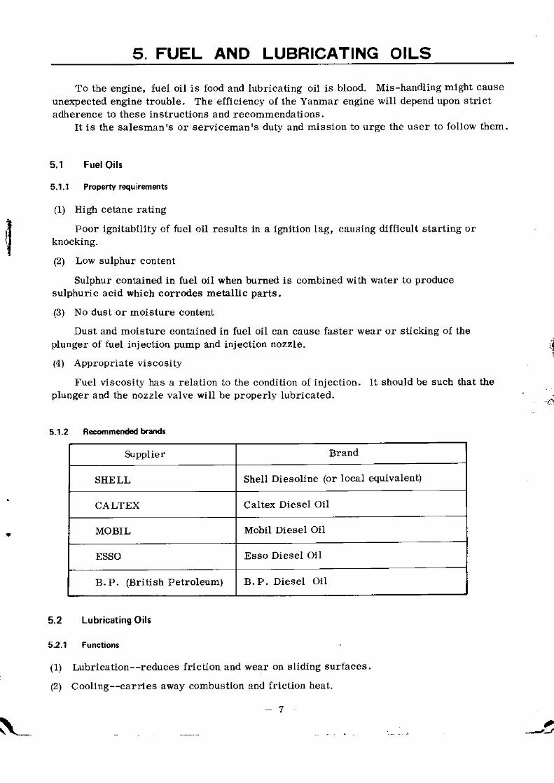
5.r.2 R*mmend b.ands
Suppl ie. BraIto
SHELL Shell Diesoline (or local equivalent)
CALTEX Caltex Diesel Oil
MOBIL Mobil Diesel oil
ESSO Esso Diesel Oil
B. P. (British Petroleum) B. P. Diesel OiI
Lubricating Oils
5.2.1 Functions
(1) Lubrication--reduces friction and wear ou sliding surfaces.
(2) Cooling--carries away combustion and {riction heat.
,7
.,n

(3) Air-tightening--k€eps the cylinder air-tight, prevents escape of compressedair and operating gas.
(4) Cleaning--carries away carbon (combustion product) and intelnal dust.
(5) Rust prevention--keeps parts from rust.
Today, improved engines call for Ngh-quality lubdcating oils. Oil companiesare now using a [umber of additives to improve the properties of their lubricaung oils.
5.2.2 Classification by viscositv
Lube oil viscosity should be so selected as to suit the ambient temperature.
SAE-Viscosity Table
tI
F
SAENo.
.. o 'F ( 17.8"C) I l0oF ta8 aoc)
Sayboli unive'sal Kinematicviscosity. CSt
$ybotl uoiYersarviscosiry. CSI
lo'c
5W below 4,000 below 869
10w 6,000a-l 2,000 1,303a-2,606
20w r 2,000b48,000 2,606b-10323
l 0-2ec
20 45-58 513.9.62
30 58-70 9.62.t2.93
300c
40 7G85 t2.92-16.7'�1
50 8 5 - 1 1 0 16.17.22.68
8

5.2.3 Rocommended brands (t9r crankce and ge€r box,
SupplierSAE No.
below 10'C 10 - 20'c 20 - 35'C over 35"C
SHELL
Sh€ll Rotella oil10w20 /2ow
20 /20w3040
Shell Talona Oil 10w 2Q3040
50
Shell Rimula oil 20 /20\v 20 /20w3040
50
CALTEXRPM Delo Marine Oil 10w 20
3040
RPM DeIo Multi-Service Oil10w20 /20W
203040
MOBIL
Delvac Special 10w 203040
Delvac 20W-40 20w-40 20w-40
Delvac 1100 Series20-20w10w
20-20w 3040
DeIvac 1200 Series20-20w10w 20-20w
3040 50
ESSO
Estor HD r0w 203040
Esso Lube HD 203040
50
Standard Diesel Oil 10w 203040
B . P .(BritishPetroleuno)
BBBB
P. EnergolP. Venellus*P. Diesel 53P. venellus**
2 0 w , 3 0 2 0 w , 3 03040
50
* API gr.ade CB** API gxade CD
\*
9

6. TROUBLESHOOTING
The best engine will come to malfunction i{ not properly handled day after day orafter a prolonged period of service.
Locating the trouble is the first consideration. Pinpointing the trouble cause is tobe done next. Then comes a proper remedy therefore. If careless handling is the case,the operator may be instructed not to cause the same trouble.
The following lists the troubles, check points, possible causes, and remedies.
6.1 Engine Does Not Start
Check point Possible cause
1. No valve clearance. Adjust to 0, 2 mm.1. Intake/€xhaust
Fit valve with quicksuccesslve movemenls.
2. Calbod or wear on valveseat.
Renew cyl inder head. " 243. Worn valve guide.
4. lntake/exhaustvalvestuck.
Loose or uns] mmetricallltightened nozzle guard.
2. Fuel injectionnozzle
2. FaultJ or lost packing. Repair or renew.
Change oi l .Cylinder l iner.* r& piston
1. Unsuitable Iube oi l .
2. Gasoline overcharged atstart-up.
3. Stuck or worn piston ring,
2730
4. Seized or worn piston andcylinder I iner.
1. Gasket damaged (loose orunsymmetrically ti ghtenedhead).
Renew or retighten4, Gasket
1. Fuel fai lure. Supply fuel.
2. Tank cock in closed posit ion.
6. Fuel injectionpump
1. Air in pump.
Clean or renew.2. Difiy, scratched or worndel ivery valve.
3. Dirty, scratched or wornregulator needle.
Clean or renew.
Clean or renew.

Check poi[t Possible cause Remecty
?. Fuel injectionnozzle
1. Stuck or worn nozzle. Clean or renev. I9
2, Hight or low injection pres-sure.
Adjust to 160 kglcm2. 20
8. Main bearing 1. Stuck or seized. C lean o r rene r r .
9. Crankpin metal 1. Stuck or seized. Clean or rene*. 26
10. Starter operatio.r 1. Battery discharge. Recharge up to 1,26 (S. C. )a t 20 'C .
2, Kev switch fault. Renew.
3, Magnet switch fault. Correct or renew.
.1, llotor brush fault.
5. l lotor unit fault.
Renew.
Renew,
11. Batterv I. Batter! discharge, Recharge up to 1. 26 (S. G. )a t 20 'C .
2. Voltage drop (under no load) Renew i i below 12V.
12. Govelllor lever 1. Not properly adjusted. Readjust. 38F. .l
t= . I
Dilficult Start.up
4
Check point Possible cause Remedy
l . Temperature 1. Lo\a . Select suitable lube oiLUse start-up accelerator.
2. Fuel oi l l . Unsuitable qual i t ! . Change fuel oil 7
3. Inject ion 1, Stuck or worn nozzle valve. Clean or renew. 1 9
2. Low injection pressure. Ad.iust to 160 kg,/cmz. 20
3. Worn plunger. Renew.
4. Intak€/exhaust 1. Misadjusted. Reactjust. 39
5, Compression
6. Electr icequrpment
7. Heavy manualturnrng
1. Stuck or seized piston, l iner. Correct or renew.263t)
2, Stuck or seized main beadngmetal.
Correct oI renew, 33
3. Stuck or seized crankpinmetal.
Correct or renew. 26
4. Unsuitable lube oi l . Change oil 8
l t :

6.3 Bad Exhaust Color
IrFrI
F
{a:"
I
Check point Possible cause Remedy
1. Operatingconditions
1. Overloaded operation. Reduce load.
2. Output decrease 13
3. Fuel oi l 1. Unsuitable quality. Change fuel oil. 7
4. Injection 1. Stuck ot r lorn nozzle, Correct or renew. 19
2. Low injection preaaure. Adjust to 160 kg/cm2 20
5. Injection timing 1. lnjection lag. Set to 10 + 2" before TD.c.,listeoing to injection noise 40
6. Carbon deposit(Sticky)
1. Stuck or worn piston ring oroil ring.
Correct or renew.21
2. WoII I cyl inder l iner or piston.(Burning oil)
Renew. 2730
6.4 Momentary Hith{peed Revolution
Check point Possible cause Re6edy
1. Regulator handle l. Sudden operatioD, Do not move it sudd€nly.
?,. Governor syatem 1. Misadjusted lever, Readjust. 38
2. Stuck regulator spindle. Cleao and correct,
6.5 Hunting
Check point Possible cause Remedy
1. Govemorsystem
1. Misadj usted lev€r. Readjust. 38
2. Stuck regulator spiodle. Clean and correct.
3, Malfuction of No. I levershait.
Correct.
2. Injection 1. Stuck or worn nozzle, Correct or renew.
2. High or low preasure. Adjust to 160 kg,/cm2 20
3- r uel o l l L. Inferior quali ty. Change fuel oil.
4. Idjectiod timing 1. Injection advance or lag. Set to 10 + 2' before TDC.,listening to injection noise.
40
5. C rankshaft sidegap
1. Large gap. (worn mainbearing)
Renew' 33

I
6.6 Output Decrease
6-7 Knocking during Oporation
l3
Check point Possible cause Remedy
1. Compression
2. Intake/exhaustvalve
1. over/under clearance. Adjust to 0.2 mm. 39
3. Inject iod 1, Stuck or worn nozzle. Colrect or renew, 1 9
2. Pressure drop, Adjust to 160 kglcm2. 20
3. \forn plunger, Renew. 1 8
4. Scratched or worn delivery!alve.
Correct or renew.
5. Uisadjusted govemor lever. Readjust. 38
4, Fuel oi l l � L n s u i t a b l e q u 3 l i t , ! . Change fuel oi l . 7
5. Combust ioDchamber
1. Carbon deposit Remove.
6. Moving parts l. Stuck or seized cylinder linerand piston.
Correct ora renert. 2730
2. Stuck or seized crankpinmetal.
Correct or renew. 26
3. Stuck or seized main bearingmetal.
Correct or renew. 32
4. Stuck or seized piston pinand pin metal.
Correct or renew.27
Check point Possible cause Remedy
1. Tighteningparts
1. Loose end nut. Retighten.
2. Irose connecting rod boltsand nuts.
Retighten.
3. Other tightening parts loose, Retighten,
2. Moving parts 1. Worn or seized crankpinmetal.
Renew, 26
2. worn or seized mai! bearingmetal.
Renew. 32
3. worn or seized piston pin andpin metal.
Renew. 27
3. Intake/exhaustvalve
1, Large cleaiance. Ad jus t t o 0 .2 mm. 39
a._

Cbeck point Posaible cause Remedy
4. Fuel oi l . 1. Unsuitable quality. Change fuel oil. 7
5. Injection. 1. Stuck or worn nozzle. Correct or renew, 1 9
2. High or low pressure. Adjust to 160 kglcm2. 2 0
6.8 Sudden Engine Stop
Check point Possible cause Remedy
1. Heavy manualrurrung.
1. Seized main bearing metal. Renew.
2. Seized crankpin metal. Renew, 26
3. Seized pistod and cylinderI iner,
Renew. 2730
2. Inject ion
3. Compression.
1. Fuel fai lure, Supply fuel oil
2. Unsuitable.lual i ty. Change fuel oi l
5. Load. 1. Overload. Reduce load.
F
14"t 6,9 Lub€ oil Leak
6.10 Fuel Oil Leak
Check point Possible cause Remedy
1, Contact surfacesof parts.
1. Loose bolts and nuts. Retighten.
2. Scratched packings. Renew.
2. Sliding parts. 1. Scratched or worn oil sealsor shafts.
Renew.
3. Lube oil tube. 1, Loose bolts or scratched. Retighten or renew.
Check point Possible cause Remedy
1. Firel tank cockreutlner.
1. Loose bolts and nuts, otscratched packings.
Retighten, or rene\r.
2. Fuel oi l pipe. 1. Loose or scratched bolts. Retighten, or renew,
3. Oil reaervoir. 1. Defective plunger tight€ningnuts, loose setbolts, damagedpackings, or scratchedcodtact surfaces,
Retighten, or renew.
23
l4

a
6.11 Water Leak
6.12 Cooling Waer Failure
6.13 Clutch SliDa
15
\-
Check point Possible cause Remedy
1 . Rocke r cove r 1. Loose bolts and nuts. Retighten.
2. Damaged packings. Rene\r.
2. Cylinder head, 1, Crack caused by fteezing. Renew.
2. Loose bolts. Retighten. 24
3. Damaged gaskets. Renew.
3, Cylinder body. 1. Crack caused by freezing. Renew.
4, Inside of crank-case .
1. Scractched liner packing. Renew.
Check point Posaible cause Remedy
1. Kidgston cock. 1. Dirty mouth. Clean.
2. Cock in closed posit ion, Open cock.
2, Cooling waterpipe flange.
1, Scratched packings, Renew. 22
2. Loose t ightening parts. Retighten.
3. Pump drivebelt.
1. Slack belt, Tighten. Adjust finger-depressed deflexion to5 -? mm.
4. Cooling waterpump.
1. Scratched or worn imDeller, Renew.22
Check point Poasible cause Remedy
1. Frict ion disc. 1. Worrl disc. Renew if total wear on bottsides er(ceeds 2 mm.
2. Spring. 1, Weakened ot broken. Renew.

7. WEAR LIMIT OF EACH MAIN PART
DescriptionYSES YSEl2
std. dim. , wear limit,mm
std. dim, , wear l imit,mm
,l
Q
Clearance between cylinderliner and piston
0 : 1 0 9 0 . 3 8 0 . 2 0 8 0 . 4 3
Clearance between piston pinand piston pin metal
0 . 0 3 7 5 0 . 3 0 0 . 0 3 7 5 0 . 3 0
Clearance between crankpinand cranl<pin metal
0 . 036 0 . 14 0 . 0 3 6 0 . 1 7
Clearance betweeocrankshaft journaland crank metal
0 , 0 5 7 0 . 1 ? 0 . 0 5 9 0 . 1 8
0 . 0 7 0 . 1 8 . 0 . 0 6 8 0 . 2 1
Clearance between intake/exhaust valve and valve guide 0 . 0 5 2 5 0 . 3 0 . 0 5 2 5 0 . 3
Piston ring end clearance 0 . 3 0, -1 1 . 5
F:
Cylinder l iner top I. D. - 0 . 3 0 85 ' 0 .34
Piston skirt O.D. 75 -0 .23 85 -0 .26
Piston pin O. D. 23 - 0 . 1 0 2 8 -0 . 11
Piston pin metal I . D. + 0 . 1 0 2a + 0 . 1 1
Crankshaft pin O.D. - 0 . 1 3 -0 .
CrankshaJt journal O. D. 44 -0 , 13 - 0 . 1 6
Crankpin metal I. D, 42 + 0 , 1 1 +0 .12
Main bearing metal I. D. 1 1 + 0 , 1 3
Top piston ring(chrome?lated)
Breadth 2 , O - 0 . 1 5 -0 . 15
Thick-ness
-0 . 33 3 . 7 -0 . 37
s,!
2nd & sr.d pistonrings
Breadth 2 . 0 -0 . 15 2 . 5 -0 . 15
Thick-ness
- 0 . 3 3 3 . 7 -0 . 3?
Oil r ingBreadth g o 4 . 0 -0 . 15
Thick-nesa
3 . 3 -0. 33 3 . 7 -0 . 3?
lntake/exhaustvalve sping
Freelength
- 1 . 5 t o- 2 . O . .:.
- 1 . 5 t o- 2 . 0
rl
b't 'I
- 1 6

Models YSE8 YSE12
Max. permissiblediameter of groundcrankshaft
P in 4r .5 Q 45 ,5 A
Journal 43.5 4) a 1 . 5 0
8. INSPECTION AND SERVICING OF MAIN PARTS
a8.1 Fuel Iniection Pump.and Nozzle
Both the fuel injection pump and the fuel injection valve (nozzle) are super-highprecision finished to atomize fuel oil at an elevated pressute so it can be intimatelymixed wit l air,
Care should, therefoie, be taken that they do not get dirty or scratched duringdisassembly and reassembly. And it is important that the] are washed in clear cleaningoil before rea6sembly,
8.1.r Fuel iniection pump
Disassembled Pump
I
' - t
Resuraio. body pack,nq
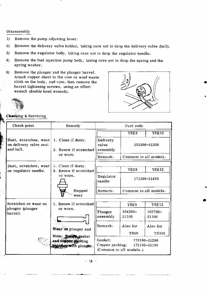
Disassembly
1) Remove the pump adjusting lever.
2) Remove the delivery valve holder, taking care dot to drop the delivery valve (ball).
3) Remove the regulator body, taking care not to drop the regulator needle.
4) Remove the fuel injection pump body, taking care not to drop the spdng and thespring washer,
5) Remove the plunger and the plunger barrel.Attach copper sheet to the vise o! wind wastecloth on the body, and vise; then remove thebalrel tightening screws, using an offset
' wrench (dolrble head wrenchi.
Cloeking & Servicing
a
i
hi
FF
Check point Remedy Part code
iust, scratches, wearon delivery lalve seatand ball.
1 .
2 .
Clean if dusty.
Renew if scratchedor wotn.
YSES YSEI2
Deliveryvalveassembly
101300-51300
Remark: Common to all models.
Dust, scratchea, wearon regdator oeedle.
1. Clean if dusty.2, Renew if scratched YSE8 YSE12
Regulatorneedle
171590-51420
Remark: Common to all models.
Scratches or wear onplunger (plungerbarrel)
t.l:.'. ,
1. Renew if scratched
Gasket: 172100-51290Copperpacking: 1?2100-51190(Common to al l models. )
YSE8 YSE12
Plungeraeaembly
104200-51100
102700-51100
Remark: AIso for
TS6O
Also for
TS lO5
a

Reassembly
1) Tighten the plunger assembly.Check that the plunger moves lightly whiletightening it gmduauy by use of an offset
2 l
4 l
Place the spring and the spritrg washer.
Attach the pump bodj' to the engine.
Tighten the regulator, with the regulator body turned counter-clockwise to thedegree within which it does not come off. Check that the regulator spindle moveslightly.
5) Tighten the delivery valve.
Note: This completes the reassembly; however, air venting of fuel injection pump andadjustment of governor lever are still necessary for engne start-up.
8.1.2 Fuel iniection valve {nozzle)
Ao#6
e-
-€
ffnEUJr-l
Ir-
DiBaBsembly
1) Detach the fuel iujection valve.
2) Remove the fuel injection valve lock nut.
3) Remove the nozzle valve assembly,
If it is difficult to take out the nozzle body,drive it out by hammering the pipe (Bee fig. ).Do not strike with a dliver or the like, for thevalve tip might be damaged.
Foel varve spring horder
Fuelv6lv€ spnng horde. Pa.k'ngNozzle sprin9 adju{'ng plate
a

4) Take off the fuel injection valve spring holder, taking care not to drop the nozzle springadjusting plates.
Checking & Servicing
Check point Remed] Part code
NozzIe valve.Dusty, stuck,scratched or worn.
I2
Clean if dusty.Clean or renew ifstuck.Renew ifscratched.Renew if worn.
YSES YSE12
Nozzlevalve
172100-5 i000
Remark: Common to al l models. t
ReasBembly
Verification
After completion of the reassembly, verify that the injection pressure and the spraynonnal or as rated. A nozzle tester simplifies the verification. but if itrs not
to left andfit the tuel injection valve and swing the V pulley of the power take-off shaltr ight.
venting is necessar'y.
l) Attach tbe inter spi ldae. st i ' ing seat, nozzle spring, adjusting plate, packing, andnozzle spdng holder.to the fuel injection valve body. Be sure of the spring side ofthe spdng seat, and do not drop the spring adjusting plates-
) Attach the nozzle valve and the nozzle bod! to the fuel injection valve bodJ
) Vise the fuel injection valve and t ighten various parts.
from areavailable,
Injectionpressurenot normal.
1. Juclgement using nozzle tester.
2, Judgement without using nozzletester.
(Low pressure: large fuelparticle size, or bad exhaustcolor. ).
High pressure: small fuel part icleaize, or knocking,
Adjust to 160 kg/cmz.
* Adjusting plate thickness andpressures
Y S E S YSE12
Nozzlespnngadjustingplate
1 r0250-53150
Sold in sets.
I
2t
Check point Judging criterion & remedy

0. 1 mm approximately0 . 2 m m0 . 3 m m0 . 5 m m
Normal spray angle
t Kg/cf i -
14 kg/cm221kg/crrl235 kg/cm2
21
Abnormal spray fon!
Check tle iniection pressure andclean or retrew nozzle valve.
8.1.3 AiI ventang
The tuel injection system includes the fuel talk, the fuel injection pump, the fuel
injection pipe and the fuel injection nozzle.
Air contained in this fuel iniection system prevents fuel injection.
In case of Juel failure and \phen the fuel injection pump is disassembled, air ente!€
the fuel injection system.Purge the system of air.
Air Venting Procedure
ril
*
1) . Place the fuel cock inthe open position.,
r+
;*q *-=-i----.

Loosen the nipples atboth ends of the in-jection pipe, removethe injection pipe,ard place the speedcharge lever in LOwposition.
Loosen the deliveryvalve holder (by abouttwo turlrs), andwhen bubble-freefuel comes out,securely tighten t}tedelivery valve holder,and then, afterattaching the iniectionpipe, securely tightenthe tuel trrmp sidenipple.
ConJirm if tuel leakout of the nut of thefuel injectio! valveside, ard then tightsnsecurely the nut.
2l
3)
['
+)
4.2 Cooling Water Pump.
The YSE type cooling water pump, of the rotary tlpe, contains a rubber impeller; it carfeed a sufficient quantity of cooling water to all the parts at high speod as well as at lowspeed.
Disaasembled Cooling Water Pump
l'"T'Pump Pump Puhp
ihp€ll€r bcrdY
@ o
' *
- 2 2

Disassembly
1) Detach the pump assembly from the engine.
2) Remove the pump drive V pulley and key.
3 ) Remo\e l he bea r ing snap r i ng .
4) Take off the pump cover,
5) Drive out the drile shaft b]' hammering \,ith copper hammer from the impeller sideto the pulley side. (It comes off with the bealing. )
a U) Remove the rubber impeller.
7) Draw out the seal from the pump bodl'.
. 8) Remove two beadngs, one nylon packing and one rubber seal from the dlive shaft.
Checking & Servicing
Check point Remedy Patt code
Scratches or
impeller.
Renew if scratched,
Renew il the gap betweenimpeller and pump bodyside exceeds 0.5 mm.
\6E8 YSE 12
Impeller r04211- 4207 0
Scratches orweai on plppbody and coversurfaces ove!which impellersl ides.
Renew if scratched oi
Pump body
YSEs I YSEI2
104211- 42010
Pump body104211-42080
Scratches orweat on pumpseal.
Wea! or ruston bearing.
Renew if scratched orYSES YSEl2
Pump seal 104211-42100
Renew if worn or rusty.YSE8 YSE12
Bearing(6200ZZ)
24t07 -062004
.',#
Reaasembly
1) lnsert tl)e cooling water seal into the pump body and apply grease to the se,al:
2) Place two bearings, distance peace nylon packing, and rubber seal upon the driveshaft, place the assembly into the pump body, and then place the snap ring.

3) With it set in the gtoove on the drive shaft, insert the impeller into the pump body.
The ddve shaft rotates counter-clockwise when viewed from the pulley side. Be
sure the impeller is inserted correctly.
4) Place the pump body cover.
5) Attach the key and the V pulley, place the lock washer and tighten the nut,
6) Bend the lock washer.
7) Attach the pump assembly to the engine and tighten the V belt.
Adjust the finger-depressed deflection to 5-? mm.
Vedfication
the pump assembly to the engine and operate it to verify that its discharge ls as
specified betow:
a
YSE8
YSE 12
Eoo lit. /hr.
460 l i t . , /hr.
Pump shaft speed 2000 rpm(Crankshaft speed 3200 rpm)
Pump shalt speed 1900 rpm(Crankshaft speed 3000 rpm)
" If operated *ithogt water, the rubber impeller with burn. Never operate without
water!
8.3 CYlinder Head
The cylinddr head is a gasket type: the valve guides and the cylindet head are in one
piece, and a la4e diameter intake valve is used fot $eater suction €fficiency. The intake
and exhaust valves are of th€ totally enclosed and supplied lube oil with iorcedcirculation
Iubication svstem.
Disassembled Cylinder Head
intake/
rne-€ o6€
intake/
o'./..{N
:JSl\c:a'6/ l \ \ \ \ /
:li:"f " :tfj:l \\_ \L.. "".,,:{*::r'fjj} bl#"*
|lc
24

DisassemblY
1) Detach the cylinder head from the engine, remove thoroughly carbon from com-
bustion surfaces of the cylinder heed aDd from the internal surlaces of the pre-
combustion cha.mber, and then inspect arld service the va]ves.
2) Remove the split tapper collets by pressing each spring holder with spanner' They
will come off to\'rard the combustion chanber.\
:1.
a.
?
Checking & Servicing
Check point
YSES YSElZ
Intake 1042t1-11100
104511-11100
Exhaustvalve
L042ll-11100
104511-11110
Scmtches or wearon intake/exhaustvalve seatingsudace.
Renew if stepped wearor deep scratches.Fit if poor fitting otshallow scratches.(Refer to next column. )
Note: Seat width shouldbe less than 2 mm.
Lap if scratched or worn to a broader \ridth than Specified.
Lapping method(If heavily wor.n or scratched, correct with a seat cutter. )
.:i
1. Lap till scratches are gone
with coarse compound, thenwith fine compound.For finishing, use oil .
wash off the lapping compound.Apply red lead to the seat and check fitting aterthe lappinoperauon.After that, be sure to apply oil to seat.
Scratches orwear on cylinderhead valve seat.
25

wear on valveguides andvalves.
Rene\! cylinder head orvalye if worn.
YSE8 YSEl2
Intake 104211-11100
104511-11100
Exhaustvalve
104211-11110
104511- 11110
Cylindeiheacl
to42tL-11010
104507-11010
Reassembly .
lnsert tll intake and exhaust valves into the cylinder head, and secure each valve springJnt+
, sr.op witli'isparner placcd upon lhc valvP spring holder'
Check and renew (if necessaiy) the gasket.
Cla.rnp the cylinder head evenly in the diagonal direction.
rC
I2l
Cylinder head lock nut tightening torque
YSES YSET2
Tightening torque 8 . 8 \ 2 . 4
Piston and Connecting Rod Assembly
ital at its smaller end and crankpin metal at its lalger end. The piston rings are com-
posed of three pressure rings and one oil ring.
Piston and Coinecting Rod AssemblyAs Disassembled
Connecting rod lock nut tighteningtorque.
r*8ton of hidr silicon featuring a low expansion coeflicient and outstanding resistancejaw road ii ouar shaped externally. The starnp forged connecting rod has piston pin
raConnect nq ro.l ass--mb y
kc-or
YSE 8 YSE 12
Iightening torque 3
26

Diaassembly
1) Ring removal
1-1 Make bi,lo 4 cm-dia. rings of tag wire.
1-2 Slightly pull each ring and open with the wiresplaced al its ends and remove.Excessive opening will cause ring breakage.
1-3 After remola.I of all the rings, clean thering glooves,
- 2l Disassembly o{ piston and connecting rodrDThe piston and the connecting rod are connected to each other through the piston pin.
The piston pin hole has a little tigitening allo\4 ance \lhen cold. It is thelefore neces-' sary to heat the piston when it is lo be talien out or inserteci
2-l Remove t1'ro piston pin stop rings.
2-Z Heat ttlre piston pin for 15 min. in oil at oiltemperalure of 8tr C.
2-3 Take out the piston pin using the exclu-sive tool.
Checking & Sewicing
a;
Note: 1t is recommended that parts be renewed at ma-x. allowable values,
Check point Remedy
ring.
using a
Thickness
YSE8 YSEI ]
No. I ring
plated
B 2.0 0 . t 5 2 . 5 0 . 1 5
T 3.3 ,0.1J 3.7 0.37
N o . 2 &No.3 r ings
B _2.0 0 . 1 5 2.5 0 . l 5
T l . l 0.33 3 . 1 ,o.3'7
Oil dngB . 4.0 0 . 1 5 4.0 0 . 1 5
T .] .1 ,0.33 3 . 1 0.3'7
Renew iI wear exceeds max. auowable value
YSE8 YSEI2
No I ring104200-221 l0
104500- 2 2 1 l 0
N o . 2 & N o . 3rings
1042002 2 1 0 0
loi438-27l0o
Oil ring104200.22200
r03438-22200

YSE8 YSEI2
Piston104211-22020
t 04511-22020
For rin8s, se€ abov€ table.
YSE8 YSE I2
rinS groove0.037 0.30 0.037 0.30
Roflew ifclearance exceeds ma:. allowabl€ value.
ring andring groove.
using a
gauge.
Note: Nom. and max. in lhe above table represent nominal values in nm and naximum allowable values in Inn,
Standdd gap
YSE8 0.2 to 0.4 nm
YSEI2 0.3 to 0.5 mm
R€new ifthe gap exc€eds 1.5 n1m.
Renew if weal €xceeds the maJdmum allowable
YSE8 YSEI2
std. std.diam,
7 s 6 ,o.23 8 s d -0.26
YSE8 YSEI2
l M200.22300
103438.223ffi
Renew if wear exc€eds the inaximum atlowable
YSE8 YSE 12
std.
234 -o.10 286 { . 1 1
piston pin.
Measure O.D.
trsing a
a
2 8 -

Chec} poin l Rernedy
p$Ion pm
cylindergauge.
YSE8 YSEI2
42. S +0. l0 1 8 d +0.1 I
R€new ifwear exceeds the ml\inum allowable
YSES YSEI2
Piston pin r04200.23100
103438-23100
using acylinder8au8e.
Renew if wear exceeds th€ maximurn allowable
YSES YSE I:
diam,
4 2 1 +0 .1 I 4 6 6 +o.12
YSE8 Y S E 1 2
Crankpin 104200-23340
103338-23300
t
Croas-sectional views of piston rings:
i-:j.
No. 1 ring : Barrel-faced t!?e that fits exactly in liner allow-(chrode-plated) ing minidru!tr g!!s escape.
No. 2 r ing
: Tapered tj.pe that also serves to scrape oil down.
No. 3 ring
*
lE ou ""*.
Reaasembly
1) Reaasembly of piston dngs
1.1 Clean piston Iing grooves before ringplacement, preferably with ar old ring
Oroken),
Beveled tlpe that prevents oil from coming up as
well as scrape it down.
29
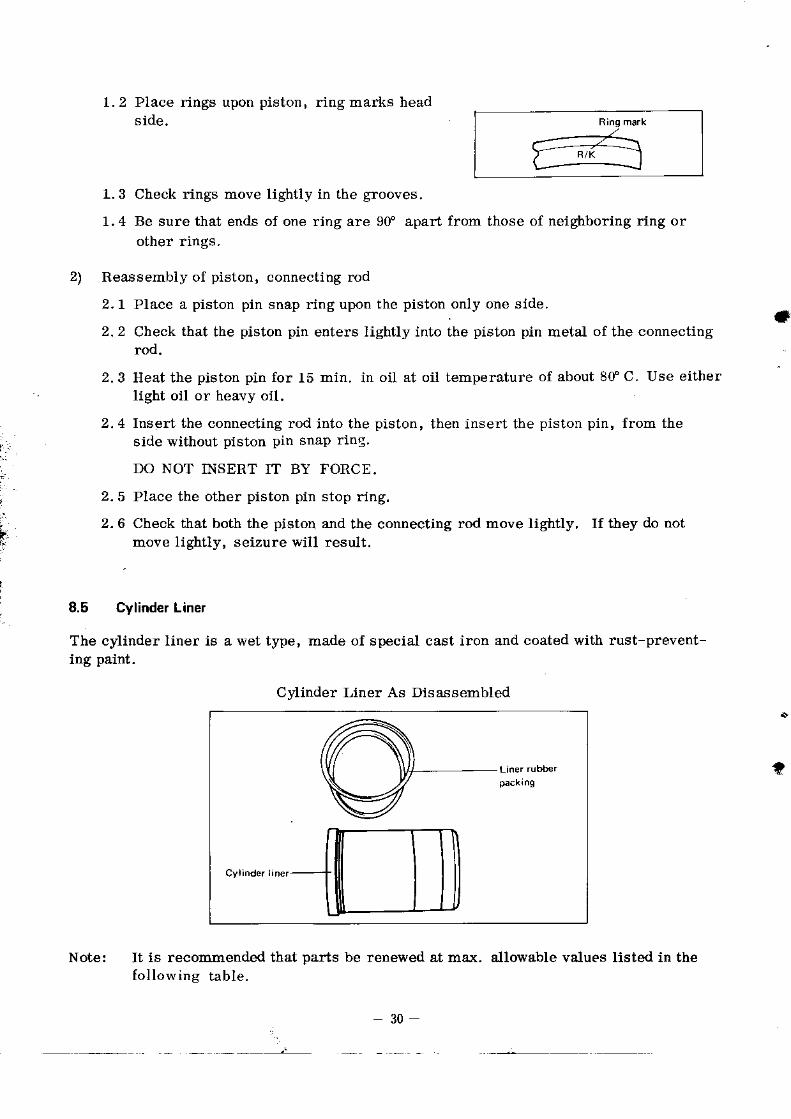
1.2 Place rings upon piston, ring marks headside.
1.3 Check rings move lightly in the grooves.
1.4 Be sure that ends oJ one ring are 9f apart from those of neighboring ring orother rings.
2) Reassembly of piston, connecting rod
2,I Place a piston pin snap ring upon the piston only one side.
2.2 Check that the piston pin enters lightly into tbe piston pin meta.l of the connectingrod'
2.3 Heat the piston pin for 15 min. in oil at oil temperature of about 8f C. Use eitherlight oil or heavy oil.
2.4 Insert the connecting rod into the piston, then insert the piston pin, from the
ll ide without piston pin snap ring
DO NOT INSERT IT BY FORCE,
, 2.5 Place the other piston pin stop ring.
, 2. A Check *Iat both the pistoq and the connectiDg rod move lightly, If they do notI lr)ove l ightly, seizure wil l result.
I_ 8.5 Cylinder Liner
The cylinder liner is a wet type, made of special cast iron and coated with rust-prevent-ing paint.
Cylinder Liner As Disassembled
*
?
Note: It is recoEmended that parts be renewed at max. allowable values listed in thefol lowine table.
30

*
Check point Remedy
Scratches or wear on cylinder
(l) M€asure using a cytridercauge.
Renew if such wear or scralch exceeds themaxinuln allowable value.
Renew ifrhe gap exceeds l�0 mnl. on bolhYSE8 and YSEI2 modeis.
Renew if obsened srepless.
YSES YSE12
Noninalinside
Max.Noininal
Max.
1 5 6 +0.30 8 s d +o.34
YSE8 Y S E I 2
Cylinderliner
t 0 4 2 1 1,0t 100
1 0 4 5 1 I- 0 1 1 0 0
Liner
packing
101204-01300
103388{1300
(2) Another sirnpler rnethod.
Ins€rt a new ring into No.l rinSposition of liner, tlEn measur€th€ ring end gap using a clea-ance guage.
Note: The ring insertedshould be perpendicular toliner.
(3) Visualdet€rmination
*,
Renewal
1 ) Attach lock nuts to two cylinder head set-bolts positioned slmmetrically to eachother, and pull out the liner with the linerpuller.Drive the nuts till four to five threadscome into sight,
Remove the liner rubber packing.2l
3 l
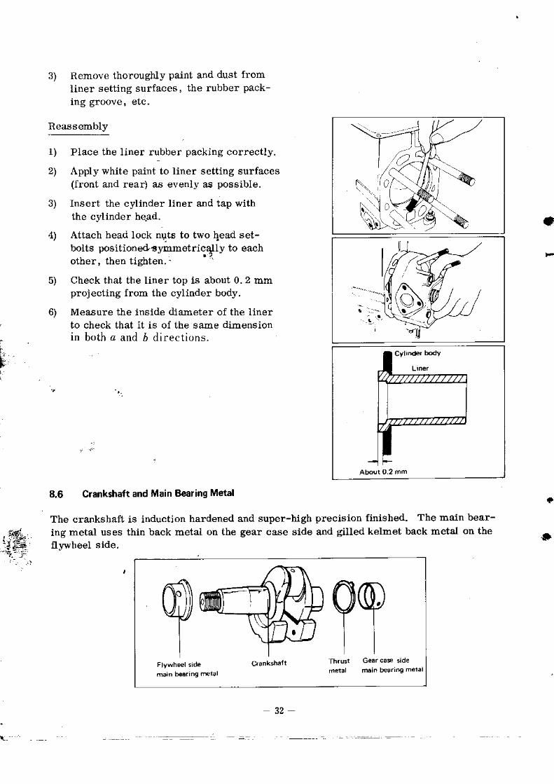
1 )
2l
3) Remove thoroughly paint and dust fromliner setting surfaces, the rubber pack-ing gioove, etc.
Reaasembly
PIace the liner rubber packing correctly.
Apply white paint to liner setting surfaces(front and rear) aa evenll' as possible.
Insert the cylinder liner and tap withthe cylinder he.ad.
Attach head Iock nuts to two 4ead set-bolts oositioned!vmmetricall v to eachother, then t ighten.- '
Check that the li[er top is about 0.2 mmprojecting from the cylinder body.
Mea.sure the inside diaroeter of the linerto check lhat it is oI the sa.me dimensioni n b . t h a a n L l 6 d i r e c t i ' , n s .
8.6 Crankshaft and Main Bearing Metal
The crankshaft is induction hardened and super-high precision finished. The main bear-
ing metal uses thin back metal on the gear case side and gilled kelmet back metal on theflvwheel side.
..iK3)
4)
5)
6)
(r
a
:..&.-i5=
$
32
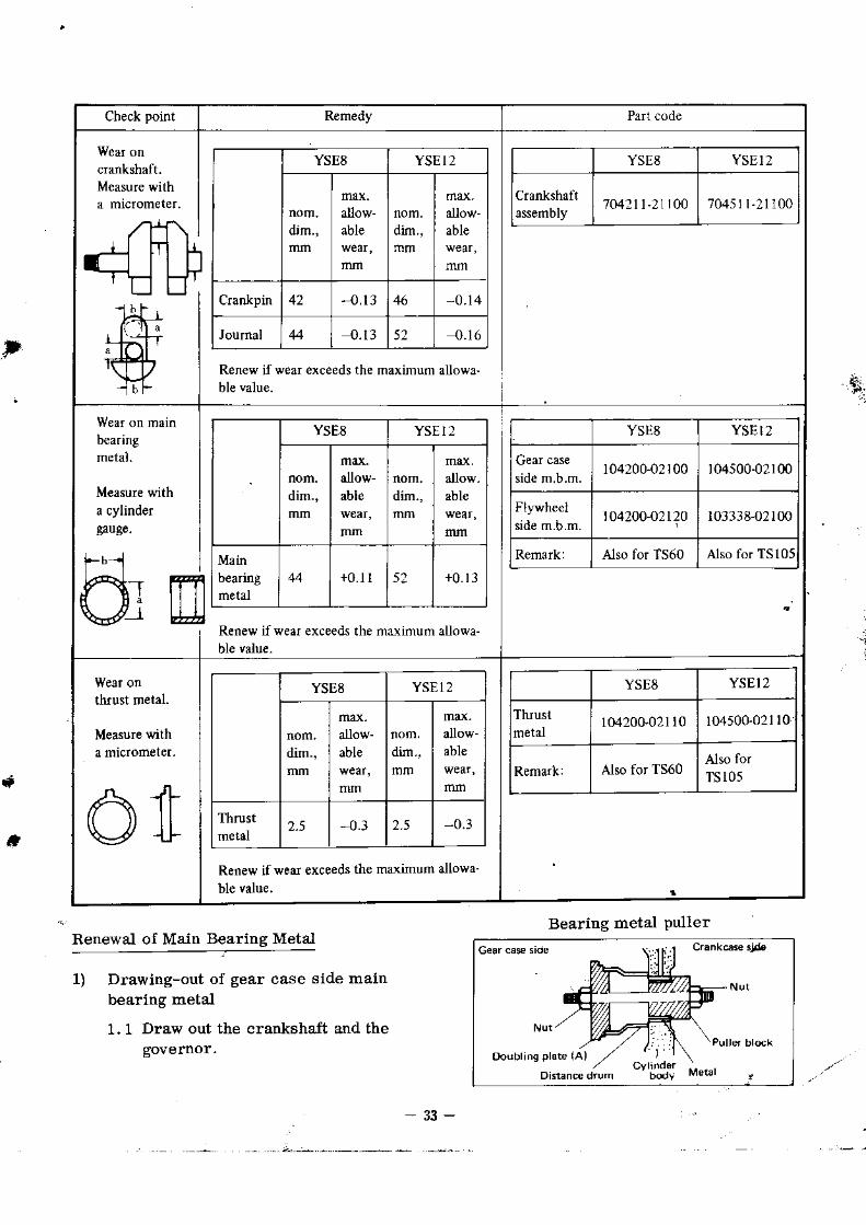
Check point Remedy
YSE8 YSE I2
dim.,alow-able dim.,
allow-able
Cranlpin '{ . l3 0 . l 4
0 .13 52 { . t 6
Renew ifwear exceeds the maximum alowa-
YSE8 YSEI2
Cranlshaftassembly 7 0 4 2 1 1 , 2 1 r 0 070.151 l-21100
beanng
a cylindergnce.
Renew ilwear exceeds the mrximum allowa-
YSE8 YSEIz
able dim., abl€
Mainbearing + 0 . 1 I 52 + 0 . 1 3
YSts8 YSEI2
104200-02100r04500-02r00
Flywheel104200-02120 103338-02100
Remark: Also for Ts60 Also for TSl05
Renew if wear exceeds the maximum allowa-
ble value.
YSE8 YSEI2
dim., able
Thrust -{.3 2.5 ,0.J
YSE8 YSEI2
Thrusi 1M200-021l0 10450G02110
Remark: Also for T560 TSl05
. i,r
f
*
Renewal of Main Bearing Metal
1) Drawing-out of gear case side mainbearing metal
1.1 Draw out the cranksha-ft and thegovemor.
Bearing metal puller
3 3 _

1.2 Mount the bearing metal puller,
1.3 Insert the bearing metal puller intothe bearing metal, draw out bear-ing meta-l by tightening the pullernut.
2) Insertion of gear case side main bear-ing meta.l
2,1 Clean the bearing metal fitting sudaceof the cylinder body.
_ .t.:i2-.2 Reassemble the bearing metal pullerfor metal insertion-
2.3 Place a new bearing meta-I upon thebearing metal insertion tool, withthe chamfer'ed side of the bearingmetal contour facing the cylinderbody.
2.4 Insert both the bearihg metal in-sertion tool and tbe beadng metal
. into the bearing metal hole from thecrankca.se side.
Bearing metal insertion tool
tt
l.s
,
f
- ' ' . .
:.
At,With tbe oil holes'Hy and of the'b(
o.'r ttr" "yriou#b
agfeerng exacthe bearing m
rnetalthe nut till
2.6 Remove
Drawing-out of flWheel side main bearrtrgmetal
3.1 Remove the oi l seal.
3.2 Draw out the bearing metal in thesame way as for dra\,ring-out ofgear case side main bea ngmetal, using the beadng metalPuL le "
?
-t
3)
i

Insertion of fl)atrheel slde main bearingmetal
4.1 Clean the bearing metal fittingsurface of the cylinder body.
4.2 Mark off a l ine on wbicb knock pinis to be located.
4.3 Let the marked-off line oD the bear-ing metal meet exactly v/ith tbe fly-wheel housing lock groove, aadinderJ the wooden insertion tool iotothe bearing metal fully with the useof a hammer.
4.4 Remove the insertion tool, andcheck that tbe knock pin and the lockgroove as weU a"3 oil holes agreecompletely.
4.5 Attach tlle oiL seal.
f3
8.7 Electf ical EquiDment
The electric starter for the YSE sedes dresel engrnes, djrectly coupled to bh€ flvwheel
housing, starts the engine, in engagement with the ring gear of the fl)'wheel. The generalor
is driven by the V belt on the power take-off pulley.
WIRE DIAGRATI FOR YSE SERIES
t
A
l;'''':
a

1 .
2 .
3 .
The instrument panel can l,.e oationally located withir tea.i, ol iire /::re L.1rness.
Fully tighten the terrninals ancl apply grease.
Recheck after wiring.
(Note) Do not operate the engine with the starter cable removed from the battery,for overheated generator might cause trouble.
Specifications
YSES YSE12
Model s114-134 s l14 -134
Voltage 72y 72V
Output 1 .oKW 1. OKW
Gear ratiotr4/9 =72. 65
r26/s =1 4 . 0
I
I
Disassemb\
1) Remove the
2) Take off the
starter from the engine.
band cover and clean the four carbon brushes.
F
Checking & Servicing
Check point Remedy Part code
Brush wear.
Measure withvernier
Renew if the total leneth is below 9. 5 mm.
Nominallength, mm
min. allowabl€length, mm
Total length 9 . 5
Weakened orbroken brush Renew if weakened or broken.
Reassembly
1) Set the carbon brush and place the band cover.
(Note) Check the (+) and (-) sides of the carbon brush.Also, secure the brush spring.
'
36
8.7.1 Starter
Ba.d cover ' -
Gear €*

!
2) After reassembly, conduct a verification test, and then check that its performanceis as specified.
* Whatever quesfion you may have about the starter reassembly, please let us
Specifications
TlpeAlteInator(Tirrill type)
Nominal output 72v-25A/5,000 rym
Earth polarity (-) side grounded
I r ! iit: : , , . . . , . : - : - . - : . . : : .==i,-='== .
Checking & Servicing
a
t
Check point Remedy Part code
Voltage aDdcurrent
1. Limit voltage: 14 + 0.5V
2. Charging current: 25A or more at14Vl5, 000 rpm
(Alternator)Measure the charging current vhen theterminal voltage of the battery is 14V witithe resistance load connected irl parallelwiti the battery.
3. Renew the assembly if the above specifica-tions are not satisfied-

9. ADJUSTMENTS
9.1 Gove.nor Lever _
9.1.1 Adjustm.nrprocedure
(1) Place the regulator remote clontrol leverin I iOPERATE' posit ion.
(2) Turn the punch mar.k on the connectingscrew toward the cylinder perpendicularlyto the pump adjusting levea,
*
*
(Note) Drive in the connecting screw till its bottom comes to the top level of thepump adJusting lever.
a
(3 )
(4)
(s)
Lightly screw in the regulator spindleclockwise,
Tighten the cross-recessed head screwfor ttre pump adiusting lever, a$d tightenthe lock nut on the other side.
I\rrn the corulecting screw (punch mart)counter-clockwise by 90', then tighten thelock nut.
(6) a. Check tbat when the p{rmp adjustiDg lever is pushed to theregulator spindle moves, boo,(Temporary high-speed rotation will result if the entsine issDindle does not move. )
Note: If the pump adiusting lever moves outside when the connecting screw is hrned by9f , go back to step (3). After that, if the governor 2nd lever moves inside, theadiustment is perfect.
cylinder side, the
started while the
[email protected]! s* stould .or .dn

After reassembly is completed, check,injection noise is nonnal.
9.1.2 Readiunmentproc€duro
Although the above stepsfollowed for simplicity'3
Inosen the connecting screw lock nut.
Turn the connecting screw (puch mark)by 90" fr:om left toward you.
Tighten the connecting screw lock nut.
9.2 Intake/ExhaunValve
9.2.1 Adjuitmertproc€dure
(1) Brtng the TD mark on the fl''wheel to themar*ed-off Iine on the flywheel housing,
Note: Set to the top dead center of compres-sion stroke (TD mark).
(2) Inosen the valve clearance adjusting screwlock nut,
(3) Adjust the clearance to 0.2 mm by meansof the valve clearance adjustitrg screvr.
Note: Adjust both suction valve and exhaustvalve clearances to 0. 2 mm whe[ theengine is cool.
(4) Fix the adjusting screw using a (-) driver,then tighten the lock nut.
9.3 Fuel Iniection Timing
6 u h ' r n i n d f h a h r n d l o t h . r f h o f r ' o lb .
(1) to (6) will do, of course, the steps sLlted below may besake.
(1 )
12)'4r
l
(3 )
a
on models YSES and YSE12,
9.3.1 Ch€cking hints
(1) Remove the cover of the(Remove the starter for
fuel injection is started at lf plus or minus t before T. D. C
starter mountiog hole.electdc starting. )
\l'.--Fi
:)
39

(2 )
(3 )
(4)
Set the TD mark of compression stroke on the flywheel to the mark on the flfrheel housing.
Place the accelerator lever in the"OPERATEiI position.
Read out the start position of tuet injection noise by swinging the power take-offpulley to left atrd right.
(5) Judge correctly by repeating the step (4) three or four times.
9.3.2 Adjustmentprocedure
?( 1 )
(2)
Detach the fuel injection pump and thepump mount.
Increase or decrease the number of thefuel injection timing adjushnent plates.
If the timing is advanced, increase thenumber of the adiustment plates; delayed,decraease the number,
0.1 mm of plate thickness isequivalent to approximately2' of time difference.
Mount the luel pump mount and the fuelpuinp.
Note: Check the{uel injectioD timing.
(3 )
ta
40

1O. DISASSEMBLY
10.1 Preparation
1) Choose a clean workshop put in order.
2) Prepare a worktable on which to place the disassembled parts.
3) Prepare wash oil and an cleaning-oil drum.
4) Prepare right tools,
10.2 Serviceman's Kit
10.2.1 Glneraltools- €
..t
.{
II
l
4 l
. { . k, l 2 } - - G
4 + €
13 -:€ r'
1 4 -
Ae fl-
Pl)
1 5 \
iL6
n
1".
8 0 - : - r
a
Tool Remad<s Tool Remarks
1 Spanner 1 0 x 3 9 Pinchers
2 Spanner 1 7 x 9 10 Pliers
3 Spanner 22 x24 11 offs et wrench l set
4 (+) driver 12 Box spanner I set
5 (-) driver 13 Scraper
6 Iron hammer 74 Lead bar
7 Copper hammer l set
8 wooden bammer 16 Wrech forhexagonal socket.head screw

10.2.2 Specialtools
,?'4,-''- s+
!-1f-
1
5 .j,rr G
.. @"-,1r
{; / \i)
t
10.2.3 Mea$ringinstrum€nc
. .-\--_---' -N-jrb* 1
Measuring instrument Accuracy, measuring range
1 Vernier calipers 1/20 mm, 0-150 mm
2 Micrometer 1/100 mm, 0-25, 25-50,50-75, 75-100 rf in
3 Cylinder gauge 1 / I00 mm, r8 -35 , 35 -60 , 50 - I00 mm
4 Clearance gauge 0 ,05 -2mm
5 Torque wrench 0-13 kg-m
6 Nozzle tester 0-5oo kg/urQ
Tool YSEs YSE12
1 Gear puller Commercial
2 Bearing puller Commercial
3 Liner puller Also for T560 Also for TS105
Fll.r'heel puller Also tur T560 AIso for TS105
tr{ain bearing puller Also for T560 Also for TS105
0 Piston pin puller Also for T560 Also for TS105
7 Piston pin metal puller Also for TS60 Also for TS105
8 Piston insertion tool Also for T560 Also for TS105
9 Main besring insertioo too l Also lbr T560 Also for TS105
1 0 Valve seat cutter AIso for T560 Also for TS105
1 1 Valve lapping tool Also for T560 Also for TS105
1 2 36 mm-dia, spanner forclutch ahead shaft lock nut
Special order(Common to YSE8 and YSE 12)

10-2.4
Emery paper, emery cloth White paint Brush lvaste cloth
10.3 Precautions
(1) Prior to disassembly, refer to the instruction manual and the parts list.
(2) Use the right tools, and take care not to scratch the parts or wound yourself.
(3) When driving out a shaft or other parts, use a protective bar or a copper hammer.
(4) Place in order the disassembled parts.
(5) Check 0 marks on coupling, carn gear and crank gcar.
(6) Make proper profision for locking parts \\hich gi|e incidental rotation when otherparts are moled,
(7) Take care not to scratch oi l seals and other parts.
(8) For total disassembly, discharge beforehand lube oil, cooling $ater, and fuel from
the crar*case, and from the gear case.
,10.4 Clutch Disassemblv Procedure
13
Step -?rocedure TooIs Illustration
1 Remove one cotter pin, oneslotted Dut and one $oodruffkey for shifter.
PinchersSpanner 1?
2 Remove the two setbolts forclutch housinga A and B,and then two springwashers by hard.
Spanner 17
3 Detach one slide shaft.
4. Pry separate the housing Bfrom the housing A.
Note: Positioning claws andsprings leap out.Remove three claws andthree spridgE.
(-) Drive

Step Procedure Tools Illustration
5 Drive out two connectingspectacle link pins, fiom theholding friction the holdingfriction disc side.
Hammer protectivebar
6 . Detach the clutch housing Aassembly.
7 . Detach oDe piece of wire andfive bolts from the ahead side.
PinchersSpanner 13
8 Remove one ahead frictiondisc and one friction disckeep plate.
9 Remove one holding frictlotrdisc.
1 0 Remove one ahead shaft locknut,Note: Completely flatten thelock washer,Remove one lock washer.
(-) DdveHammerSpanner 36
11 Pull out one bearing from theclutch case rear box side.
Bearidg puller
Pull out one small aheadgear, one key.
Gear puller
,'q*
'.
t
- 4 4
i

step Procedure Tools Illustration
Remove one ahead shaft (llithbearing).
Remove one piece of \r'ire andfive bolts to detach one fric_tion disc assembly and onebearing from the astem gear.
Pull out one ahead shaft bearing(housing A side).
Bearing puller
a
rh!-
45

Disassembled Clutch
II
F
-Q@
*&enlt\#isx
46

ITEX{ PART NAME ITEM PART NAME
1 Housing A l 7 Ball bearing 6005
2 Housing B 1 E Shift ing sha{t bush
3 Set piccc for V lerer 19 Feather kel 7 20
'+ Setbolt for V lever set piecc 2 0 BaIl bearing 6205 ZZ
5 Washer 27 Bo l t M10 , 45
6 l ' r ict ion disc 2 2 Setbolt and wire for keep plate
7 Frict ion cl isc cla\ \ 2 3 Bo l t M10 . 30
8 Frict ion disc c1a$ spring 2 4 Shifting shaft
9 Frict ion disc keep plate 2 ) Spring
1 0 Keep plate \trasher 2 6 Spring holder
11 Ahead shaft 2 7 Ket' 4 x 13
1 2 Reversing gear 2 8 V lever
1 3 Small ahead gear 29 Link
1 4 Ahead shaft lock nut 30 Link pin
1 5 washer 3 1 V lever holder
1 6 Ball bearing 6205
I
11 . REASSEMBLY
1 1.1 Precautions
' 1) Clean parts thoroughlY in oi l .
t 2l Use the right tools and assemble the engine faultlessly.
3) Apply Iube oil to rotary and sliding parts.
4) Use new packings, cotter pins and lock washers.
5) Makesub-assemblies beforehand.
6) correct or renew scratched or worn parts beforehand.
?) Take care to )venly :ighten bolts and nuts located symmetrically to each other.
8) Let the setting marks on the crank gear and the coupling agree exactly.
I s; Securely attach the cotter pins, Iock washers, wire, etc.
10) Proceed with the assembly checking that the rotary and sliding parts move smoothly.
- 4 7

12. STERN ARRANGEMENT
The following standard stem arrangements are prepared for use with the Yanmer
diesel engines YSE8(G) ancl YSE12(G). Select the optimum model for your intended use
and Hull.
1. Propeller Shaft
Direct- coupled propeller sbaftsSelect the optimum model fot the engine output and the ship size' When coupling it
to the propeller shaft of the engine, be sure to center it in correct alignment ivith
the latter.
Standard Stern Arrangement
t
I
ModelPropeller
rpm
Propeller Propeller shaftStern tubeB
diam.rn.
pitch.in.
diam.mm
length.mm
diam. Iength
YSEst l27 l 4 I
22 18 00 .16 ,1001332 1 3 s 1 /21639 1 2 7 7 /2
YSE 8G751 1 Z
2 o 2000 50 5008q8 16 7 /2 1 1
109 3 1 0
YSE121113 1 5 1 0
25 2000 .50 5001316 I1518 1 3 I r/2
YSET 2G?18 19
2t3 2400 56 650849 1 8 1 3980 l 2
Notei Standard propeller is of integrated 3 blades type lt is madc of
manganese bronze, having an area ratio of 0' 36'
a
48

_ \
' i ,r .;]"..t 1 +
l ' . : ,
-
k : : ' . ,
i 4', - ''-'
d"s.l
i