contents · “four wheeling” supplement included with 4wd and utility type vehicles. ... on...
TRANSCRIPT
Before driving
Introduction 2
Instrumentation 4
Controls and features 15
Seating and safety restraints 79
Starting and driving
Starting 106
Driving 111
Roadside emergencies 145
Servicing
Maintenance and care 165
Capacities and specifications 211
Customer assistance 222
Reporting safety defects 234
Index 235
All rights reserved. Reproduction by any means, electronic or mechanicalincluding photocopying, recording or by any information storage and retrievalsystem or translation in whole or part is not permitted without writtenauthorization from Ford Motor Company.
Copyright r 1998 Ford Motor Company
Contents
1
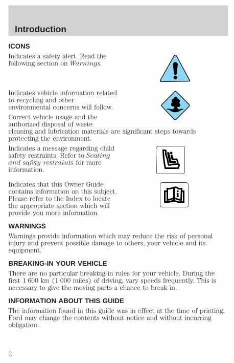
ICONSIndicates a safety alert. Read thefollowing section on Warnings.
Indicates vehicle information relatedto recycling and otherenvironmental concerns will follow.
Correct vehicle usage and theauthorized disposal of wastecleaning and lubrication materials are significant steps towardsprotecting the environment.
Indicates a message regarding childsafety restraints. Refer to Seatingand safety restraints for moreinformation.
Indicates that this Owner Guidecontains information on this subject.Please refer to the Index to locatethe appropriate section which willprovide you more information.
WARNINGSWarnings provide information which may reduce the risk of personalinjury and prevent possible damage to others, your vehicle and itsequipment.
BREAKING-IN YOUR VEHICLEThere are no particular breaking-in rules for your vehicle. During thefirst 1 600 km (1 000 miles) of driving, vary speeds frequently. This isnecessary to give the moving parts a chance to break in.
INFORMATION ABOUT THIS GUIDEThe information found in this guide was in effect at the time of printing.Ford may change the contents without notice and without incurringobligation.
Introduction
2
SPECIAL NOTICES
Using your vehicle with a snowplowFor more information and guidelines for using your vehicle with asnowplow, refer to the Driving chapter.
Using your vehicle as an ambulance
Do not use this vehicle as an ambulance.
Your vehicle is not equipped with the Ford Ambulance Preparationpackage.
Notice to owners of utility type vehiclesBefore you drive your vehicle, please read this Owner’s Guide carefully.Your vehicle is not a passenger car. As with other vehicles of this type,failure to operate this vehicle correctly may result in loss of control or anaccident.
Be sure to read Driving off road in the Driving chapter as well as the“Four Wheeling” supplement included with 4WD and utility type vehicles.
Notice to owners of F150 5.4L Supercharged “Lightning” vehiclesBefore you drive your vehicle, be sure to read the “SVT Lightning TruckOwner’s Guide Supplement.” This book contains important operation andmaintenance information.
Notice to owners of natural gas fueled vehiclesBefore you drive your vehicle, be sure to read the “Natural Gas VehicleOwner’s Guide Supplement.” This book contains important operation andmaintenance information.
Introduction
3
P
ON
OFF
RES
SETACCEL
COAST
E
L L
HH
F
C
H
BRAKEP RN D 2
FUEL RESET
SELECTRESET
THEFT
0
20
40
60 80 00
20
40
60
MPH km/h
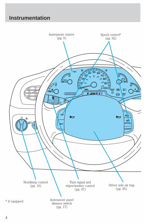
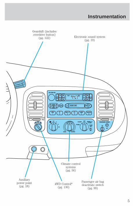
Headlamp control(pg. 16)
Instrument paneldimmer switch
(pg. 17)
Turn signal andwiper/washer control
(pg. 67)
Instrument cluster(pg. 6)
Speed control*(pg. 62)
Driver side air bag(pg. 95)
* if equipped
Instrumentation
4
VOL-PUSH ON
AMFM
BASS TREB BAL FADE AUTO SET
SEEKTUNE
DISCSSCAN EJ TAPE CDDOLBY 8 NR
REW1
FF2
SIDE 1-23 4
COMP5
SHUFFLE6
STFM 1
FLOOR
PANEL
LO
HI
COOL WARM
DEF
FLR&DEF
PANEL &FLOOR
OFFPASSENGER AIRBAG
OFF
OFF
ON
Passenger air bagdeactivate switch
(pg. 99)
Climate controlsystems(pg. 56)
Gearshift (includesoverdrive button)
(pg. 122)
Auxiliarypower point
(pg. 18)4WD Control*
(pg. 130)
Electronic sound system(pg. 19)
Instrumentation
5
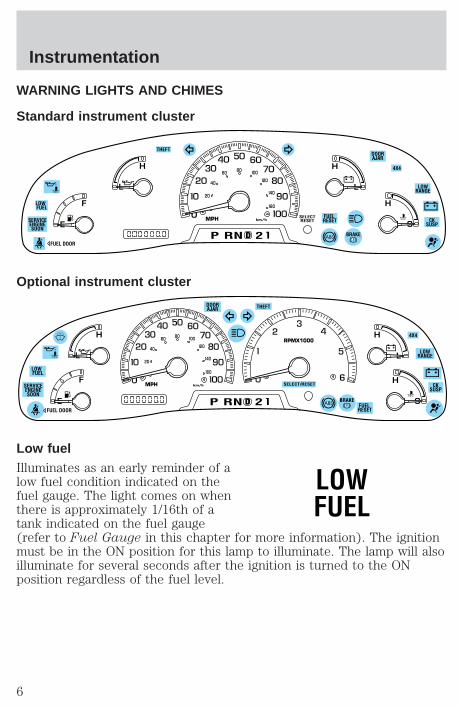
WARNING LIGHTS AND CHIMES
Standard instrument cluster
Optional instrument cluster
Low fuelIlluminates as an early reminder of alow fuel condition indicated on thefuel gauge. The light comes on whenthere is approximately 1/16th of atank indicated on the fuel gauge(refer to Fuel Gauge in this chapter for more information). The ignitionmust be in the ON position for this lamp to illuminate. The lamp will alsoilluminate for several seconds after the ignition is turned to the ONposition regardless of the fuel level.
0
E
L L
HH
F
C
H
DP RN D 2
FUEL RESET
DOORAJAR
SELECTRESET
4X4
LOWRANGE
CKSUSP
THEFT
FUEL DOOR
SERVICEENGINESOON
LOW FUEL
20
40
60 80 00
20
40
60
BRAKE
MPH km/h
D
L
H
L
H
E
F
C
H
BRAKEP RN D 2 FUEL RESET
DOORAJAR
SELECT/RESET
4X4
LOWRANGE
CKSUSP
THEFT
FUEL DOOR
SERVICEENGINESOON
LOW FUEL 0
MPH
RPMX1000
km/h
20
40
60 80 00
20
40
60
LOWFUEL
Instrumentation
6
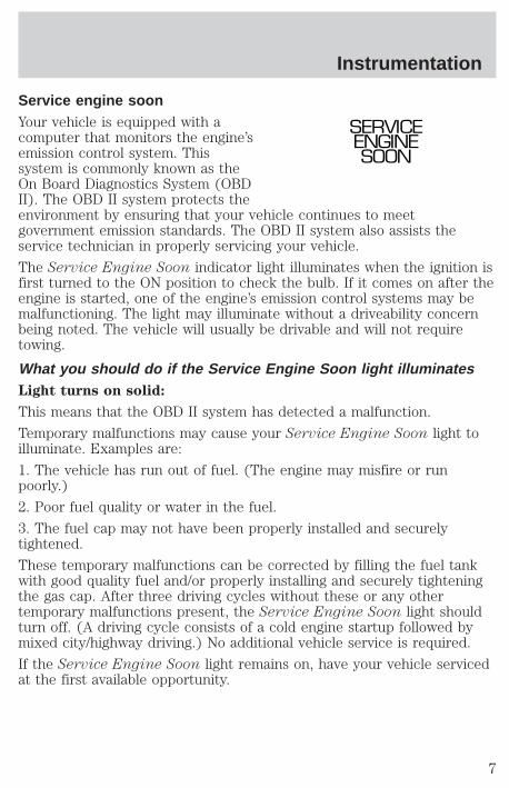
Service engine soonYour vehicle is equipped with acomputer that monitors the engine’semission control system. Thissystem is commonly known as theOn Board Diagnostics System (OBDII). The OBD II system protects theenvironment by ensuring that your vehicle continues to meetgovernment emission standards. The OBD II system also assists theservice technician in properly servicing your vehicle.
The Service Engine Soon indicator light illuminates when the ignition isfirst turned to the ON position to check the bulb. If it comes on after theengine is started, one of the engine’s emission control systems may bemalfunctioning. The light may illuminate without a driveability concernbeing noted. The vehicle will usually be drivable and will not requiretowing.
What you should do if the Service Engine Soon light illuminatesLight turns on solid:
This means that the OBD II system has detected a malfunction.
Temporary malfunctions may cause your Service Engine Soon light toilluminate. Examples are:
1. The vehicle has run out of fuel. (The engine may misfire or runpoorly.)
2. Poor fuel quality or water in the fuel.
3. The fuel cap may not have been properly installed and securelytightened.
These temporary malfunctions can be corrected by filling the fuel tankwith good quality fuel and/or properly installing and securely tighteningthe gas cap. After three driving cycles without these or any othertemporary malfunctions present, the Service Engine Soon light shouldturn off. (A driving cycle consists of a cold engine startup followed bymixed city/highway driving.) No additional vehicle service is required.
If the Service Engine Soon light remains on, have your vehicle servicedat the first available opportunity.
SERVICEENGINESOON
Instrumentation
7

Light is blinking:
Engine misfire is occurring which could damage your catalytic converter.You should drive in a moderate fashion (avoid heavy acceleration anddeceleration) and have your vehicle serviced at the first availableopportunity.
Under engine misfire conditions, excessive exhaust temperaturescould damage the catalytic converter, the fuel system, interior
floor coverings or other vehicle components, possibly causing a fire.
Air bag readinessMomentarily illuminates when theignition is turned ON. If the lightfails to illuminate, continues to flashor remains on, have the systemserviced immediately.
Safety beltMomentarily illuminates when theignition is turned to the ON positionto remind you to fasten your safetybelts. For more information, refer tothe Seating and safety restraintschapter.
Brake system warningMomentarily illuminates when theignition is turned to the ONposition, the engine is off and theparking brake is engaged. If thebrake warning lamp does notilluminate at this time, seek service immediately. Illumination afterreleasing the parking brake indicates low brake fluid level and the brakesystem should be inspected immediately.
!BRAKE
Instrumentation
8

Anti-lock brake system (ABS)Momentarily illuminates when theignition is turned to the ON positionand the engine is off. If the lightremains on, continues to flash orfails to illuminate, have the systemserviced immediately. With the ABS light on, the anti-lock brake systemis disabled and normal braking is still effective unless the brake warninglight also remains illuminated with parking brake released.
Turn signalIlluminates when the left or rightturn signal or the hazard lights areturned on. If one or both of theindicators stay on continuously orflash faster, check for a burned-outturn signal bulb. Refer to Exterior bulbs in the Maintenance and carechapter.
High beamsIlluminates when the high beamheadlamps are turned on.
Anti-theft system (if equipped)Refer to SecuriLocky passiveanti-theft system in the Controlsand features chapter.
Charging systemIlluminates when the ignition isturned to the ON position and theengine is off. The light alsoilluminates when the battery is notcharging properly, requiringelectrical system service.
ABS
THEFT
Instrumentation
9

Oil pressure/Engine coolantThis light will come on when thekey is in the ON position and the:
• engine coolant temperature isvery high
• engine oil pressure is low
The light serves as a notice that a system needs your attention and tocheck the engine coolant temperature gauge and the engine oil pressuregauge.
Refer to Engine coolant temperature gauge and Engine oil pressuregauge in this chapter for more information.
Transmission control indicator light (TCIL) (if equipped)The word OFF located on the endof the gearshift lever is thetransmission control indicator light(TCIL).
The TCIL may flash steadily if amalfunction is detected. If the TCIL is flashing, contact your Ford dealeras soon as possible. If this condition persists, damage to the transmissioncould occur.
Four wheel drive low (if equipped)This light momentarily illuminateswhen the ignition is turned to ON.Illuminates when four-wheel drivelow is engaged. If the light continuesto flash have the system serviced.
Four wheel drive indicator (if equipped)This light momentarily illuminateswhen the ignition is turned to ON.Illuminates when 4x4 range isengaged.
OVERDRIVE
LOWRANGE
4x4
Instrumentation
10
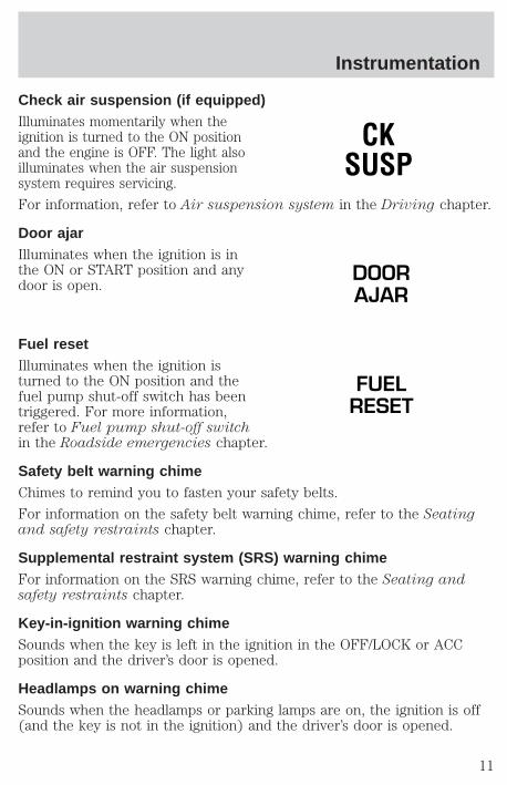
Check air suspension (if equipped)Illuminates momentarily when theignition is turned to the ON positionand the engine is OFF. The light alsoilluminates when the air suspensionsystem requires servicing.
For information, refer to Air suspension system in the Driving chapter.
Door ajarIlluminates when the ignition is inthe ON or START position and anydoor is open.
Fuel resetIlluminates when the ignition isturned to the ON position and thefuel pump shut-off switch has beentriggered. For more information,refer to Fuel pump shut-off switchin the Roadside emergencies chapter.
Safety belt warning chimeChimes to remind you to fasten your safety belts.
For information on the safety belt warning chime, refer to the Seatingand safety restraints chapter.
Supplemental restraint system (SRS) warning chimeFor information on the SRS warning chime, refer to the Seating andsafety restraints chapter.
Key-in-ignition warning chimeSounds when the key is left in the ignition in the OFF/LOCK or ACCposition and the driver’s door is opened.
Headlamps on warning chimeSounds when the headlamps or parking lamps are on, the ignition is off(and the key is not in the ignition) and the driver’s door is opened.
CKSUSP
DOORAJAR
FUELRESET
Instrumentation
11
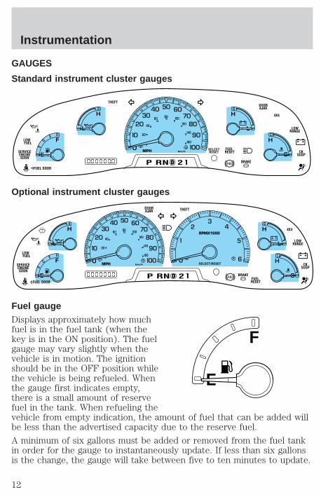
GAUGES
Standard instrument cluster gauges
Optional instrument cluster gauges
Fuel gaugeDisplays approximately how muchfuel is in the fuel tank (when thekey is in the ON position). The fuelgauge may vary slightly when thevehicle is in motion. The ignitionshould be in the OFF position whilethe vehicle is being refueled. Whenthe gauge first indicates empty,there is a small amount of reservefuel in the tank. When refueling thevehicle from empty indication, the amount of fuel that can be added willbe less than the advertised capacity due to the reserve fuel.
A minimum of six gallons must be added or removed from the fuel tankin order for the gauge to instantaneously update. If less than six gallonsis the change, the gauge will take between five to ten minutes to update.
0
E
L L
HH
F
C
H
D BRAKE
MPH km/h
P RN D 2
FUEL RESET
DOORAJAR
SELECTRESET
4X4
LOWRANGE
CKSUSP
THEFT
FUEL DOOR
SERVICEENGINESOON
LOW FUEL
20
40
60 80 00
20
40
60
D
L
H
L
H
E
F
C
H
BRAKEP RN D 2 FUEL RESET
DOORAJAR
SELECT/RESET
4X4
LOWRANGE
CKSUSP
THEFT
FUEL DOOR
SERVICEENGINESOON
LOW FUEL 0
MPH
RPMX1000
km/h
20
40
60 80 00
20
40
60
E
F
Instrumentation
12
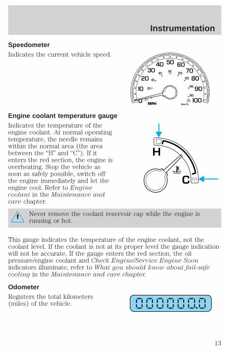
SpeedometerIndicates the current vehicle speed.
Engine coolant temperature gaugeIndicates the temperature of theengine coolant. At normal operatingtemperature, the needle remainswithin the normal area (the areabetween the “H” and “C”). If itenters the red section, the engine isoverheating. Stop the vehicle assoon as safely possible, switch offthe engine immediately and let theengine cool. Refer to Enginecoolant in the Maintenance andcare chapter.
Never remove the coolant reservoir cap while the engine isrunning or hot.
This gauge indicates the temperature of the engine coolant, not thecoolant level. If the coolant is not at its proper level the gauge indicationwill not be accurate. If the gauge enters the red section, the oilpressure/engine coolant and Check Engine/Service Engine Soonindicators illuminate, refer to What you should know about fail-safecooling in the Maintenance and care chapter.
OdometerRegisters the total kilometers(miles) of the vehicle.
0
MPH km/h
20
40
60 80 00
20
40
60
C
H
Instrumentation
13
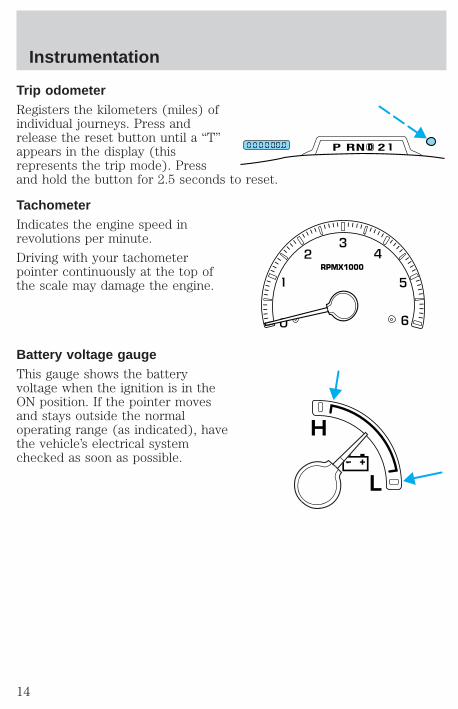
Trip odometerRegisters the kilometers (miles) ofindividual journeys. Press andrelease the reset button until a “T”appears in the display (thisrepresents the trip mode). Pressand hold the button for 2.5 seconds to reset.
TachometerIndicates the engine speed inrevolutions per minute.
Driving with your tachometerpointer continuously at the top ofthe scale may damage the engine.
Battery voltage gaugeThis gauge shows the batteryvoltage when the ignition is in theON position. If the pointer movesand stays outside the normaloperating range (as indicated), havethe vehicle’s electrical systemchecked as soon as possible.
DP RN D 2
RPMX1000
L
H
Instrumentation
14
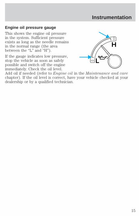
Engine oil pressure gaugeThis shows the engine oil pressurein the system. Sufficient pressureexists as long as the needle remainsin the normal range (the areabetween the “L” and “H”).
If the gauge indicates low pressure,stop the vehicle as soon as safelypossible and switch off the engineimmediately. Check the oil level.Add oil if needed (refer to Engine oil in the Maintenance and carechapter). If the oil level is correct, have your vehicle checked at yourdealership or by a qualified technician.
L
H
Instrumentation
15
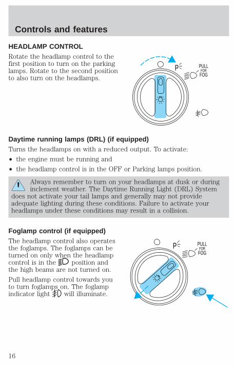
HEADLAMP CONTROLRotate the headlamp control to thefirst position to turn on the parkinglamps. Rotate to the second positionto also turn on the headlamps.
Daytime running lamps (DRL) (if equipped)Turns the headlamps on with a reduced output. To activate:
• the engine must be running and
• the headlamp control is in the OFF or Parking lamps position.
Always remember to turn on your headlamps at dusk or duringinclement weather. The Daytime Running Light (DRL) System
does not activate your tail lamps and generally may not provideadequate lighting during these conditions. Failure to activate yourheadlamps under these conditions may result in a collision.
Foglamp control (if equipped)The headlamp control also operatesthe foglamps. The foglamps can beturned on only when the headlampcontrol is in the position andthe high beams are not turned on.
Pull headlamp control towards youto turn foglamps on. The foglampindicator light will illuminate.
PULLFOR
FOGP
PULLFOR
FOGP
Controls and features
16
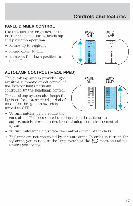
PANEL DIMMER CONTROLUse to adjust the brightness of theinstrument panel during headlampand parklamp operation.
• Rotate up to brighten.
• Rotate down to dim.
• Rotate to full down position toturn off.
AUTOLAMP CONTROL (IF EQUIPPED)The autolamp system provides lightsensitive automatic on-off control ofthe exterior lights normallycontrolled by the headlamp control.
The autolamp system also keeps thelights on for a preselected period oftime after the ignition switch isturned to OFF.
• To turn autolamps on, rotate thecontrol up. The preselected time lapse is adjustable up toapproximately three minutes by continuing to rotate the controlupward.
• To turn autolamps off, rotate the control down until it clicks.
• Foglamps are not controlled by the autolamps. In order to turn on thefoglamps, you must turn the lamp switch to the position and pulltoward you for fog.
Controls and features
17
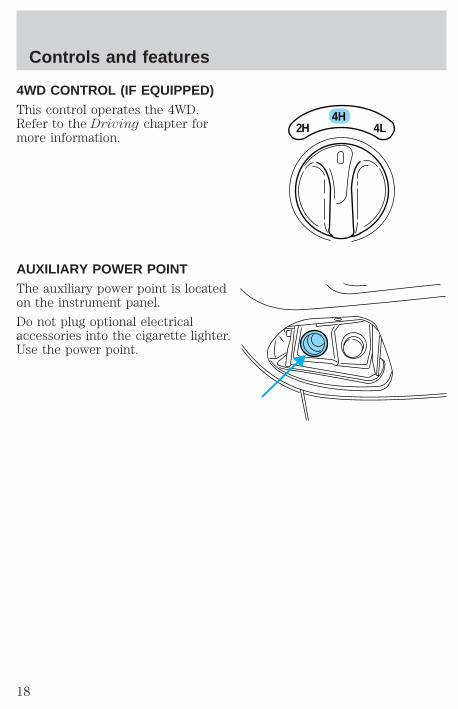
4WD CONTROL (IF EQUIPPED)This control operates the 4WD.Refer to the Driving chapter formore information.
AUXILIARY POWER POINTThe auxiliary power point is locatedon the instrument panel.
Do not plug optional electricalaccessories into the cigarette lighter.Use the power point.
4H2H 4L
Controls and features
18
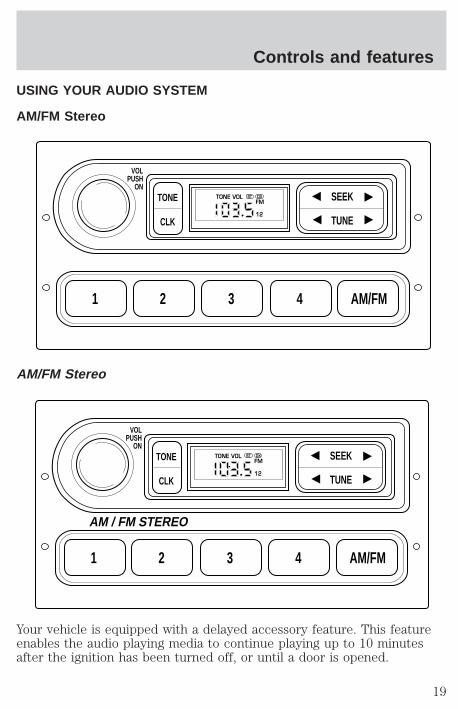
USING YOUR AUDIO SYSTEM
AM/FM Stereo
AM/FM Stereo
Your vehicle is equipped with a delayed accessory feature. This featureenables the audio playing media to continue playing up to 10 minutesafter the ignition has been turned off, or until a door is opened.
1 2 3 4 AM/FM
SEEKTONE
CLK TUNE
TONE VOL
12
FMST DX
VOLPUSH
ON
1 2 3 4 AM/FM
SEEKTONE
CLK TUNE
TONE VOL
12
FMST DX
VOLPUSH
ON
AM / FM STEREO
Controls and features
19
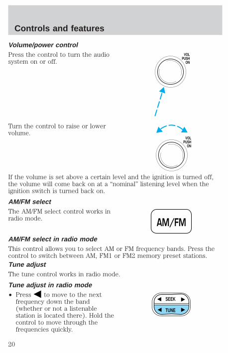
Volume/power controlPress the control to turn the audiosystem on or off.
Turn the control to raise or lowervolume.
If the volume is set above a certain level and the ignition is turned off,the volume will come back on at a “nominal” listening level when theignition switch is turned back on.
AM/FM selectThe AM/FM select control works inradio mode.
AM/FM select in radio modeThis control allows you to select AM or FM frequency bands. Press thecontrol to switch between AM, FM1 or FM2 memory preset stations.Tune adjustThe tune control works in radio mode.
Tune adjust in radio mode• Press to move to the next
frequency down the band(whether or not a listenablestation is located there). Hold thecontrol to move through thefrequencies quickly.
VOLPUSH
ON
VOLPUSH
ON
AM/FM
SEEK
TUNE
Controls and features
20
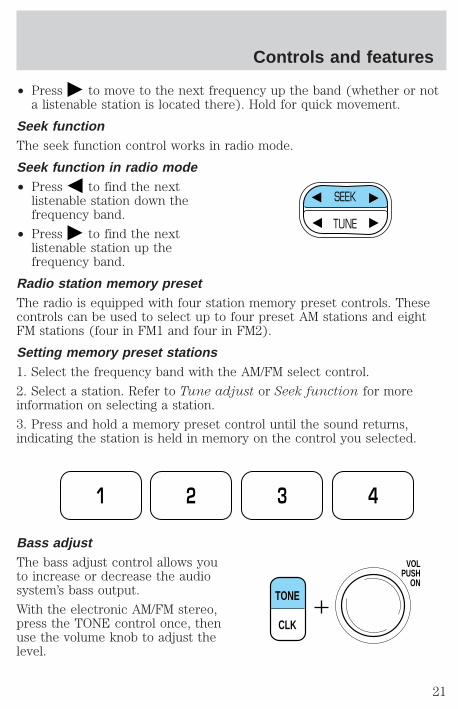
• Press to move to the next frequency up the band (whether or nota listenable station is located there). Hold for quick movement.
Seek functionThe seek function control works in radio mode.
Seek function in radio mode• Press to find the next
listenable station down thefrequency band.
• Press to find the nextlistenable station up thefrequency band.
Radio station memory presetThe radio is equipped with four station memory preset controls. Thesecontrols can be used to select up to four preset AM stations and eightFM stations (four in FM1 and four in FM2).
Setting memory preset stations1. Select the frequency band with the AM/FM select control.
2. Select a station. Refer to Tune adjust or Seek function for moreinformation on selecting a station.
3. Press and hold a memory preset control until the sound returns,indicating the station is held in memory on the control you selected.
Bass adjustThe bass adjust control allows youto increase or decrease the audiosystem’s bass output.
With the electronic AM/FM stereo,press the TONE control once, thenuse the volume knob to adjust thelevel.
SEEK
TUNE
1 2 3 4
TONE
CLK
VOLPUSH
ON
Controls and features
21
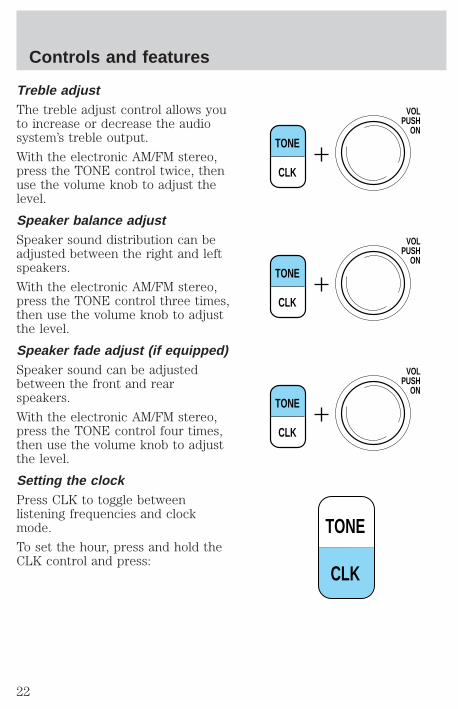
Treble adjustThe treble adjust control allows youto increase or decrease the audiosystem’s treble output.
With the electronic AM/FM stereo,press the TONE control twice, thenuse the volume knob to adjust thelevel.
Speaker balance adjustSpeaker sound distribution can beadjusted between the right and leftspeakers.
With the electronic AM/FM stereo,press the TONE control three times,then use the volume knob to adjustthe level.
Speaker fade adjust (if equipped)Speaker sound can be adjustedbetween the front and rearspeakers.
With the electronic AM/FM stereo,press the TONE control four times,then use the volume knob to adjustthe level.
Setting the clockPress CLK to toggle betweenlistening frequencies and clockmode.
To set the hour, press and hold theCLK control and press:
TONE
CLK
VOLPUSH
ON
TONE
CLK
VOLPUSH
ON
TONE
CLK
VOLPUSH
ON
TONE
CLK
Controls and features
22

• to decrease hours and
• to increase hours.
To set the minute, press and holdthe CLK control and press:
• to decrease minutes and
• to increase minutes.
The CLK control will allow you toswitch between media display mode(radio station, stereo information,etc.) and clock display mode (time).When in clock mode, the mediainformation will display for tenseconds, when the radio is turnedon, and then revert to clockinformation. Anytime that the media is changed, (new radio station,etc.), the media information will again display for ten seconds beforereverting back to the clock. In media mode, the media information willalways be displayed.
SEEK SEEK
TUNE TUNE
TONE
CLK
SEEK
TUNE
SEEK
TUNE
Controls and features
23
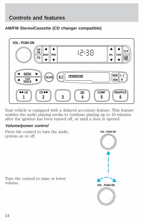
AM/FM Stereo/Cassette (CD changer compatible)
Your vehicle is equipped with a delayed accessory feature. This featureenables the audio playing media to continue playing up to 10 minutesafter the ignition has been turned off, or until a door is opened.
Volume/power controlPress the control to turn the audiosystem on or off.
Turn the control to raise or lowervolume.
FFREW
SIDE 1 - 2
BASS TREB BAL FADETAPEAMS
AMFM
CD
CLK
VOL - PUSH ON
SHUFFLECOMPCD
EJ
CD
SCANDISCS
TUNE
SEEK
321 4 5 6
VOL - PUSH ON
VOL - PUSH ON
Controls and features
24
If the volume is set above a certain level and the ignition is turned off,the volume will come back on at a “nominal” listening level when theignition switch is turned back on.
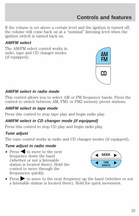
AM/FM selectThe AM/FM select control works inradio, tape and CD changer modes(if equipped).
AM/FM select in radio modeThis control allows you to select AM or FM frequency bands. Press thecontrol to switch between AM, FM1 or FM2 memory preset stations.
AM/FM select in tape modePress this control to stop tape play and begin radio play.
AM/FM select in CD changer mode (if equipped)Press this control to stop CD play and begin radio play.
Tune adjustThe tune control works in radio and CD changer modes (if equipped).
Tune adjust in radio mode• Press to move to the next
frequency down the band(whether or not a listenablestation is located there). Hold thecontrol to move through thefrequencies quickly.
• Press to move to the next frequency up the band (whether or nota listenable station is located there). Hold for quick movement.
CD
AMFM
SEEK
TUNEDISCS
Controls and features
25

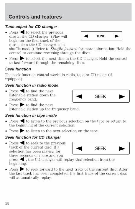
Tune adjust for CD changer (if equipped)• Press to select the previous
disc in the CD changer. (Play willbegin on the first track of thedisc unless the CD changer is inshuffle mode. Refer to Shufflefeature for more information. Hold the control to continue reversingthrough the disc.
• Press to select the next disc in the CD changer. Hold the controlto fast-forward through the remaining discs.
Seek functionThe seek function control works in radio or CD changer mode.
Seek function in radio mode• Press to find the next
listenable station down thefrequency band.
• Press to find the nextlistenable station up thefrequency band.
Seek function for CD changer (if equipped)• Press to seek to the previous
track of the current disc. If aselection has been playing forthree seconds or more and youpress , the CD changer willreplay that selection from the beginning.
• Press to seek forward to the next track of the current disc. Afterthe last track has been completed, the first track of the current discwill automatically replay.
Scan functionThe scan function works in radio orCD changer mode (if equipped).
SEEK
TUNEDISCS
SEEK
TUNEDISCS
SEEK
TUNEDISCS
SCAN
Controls and features
26
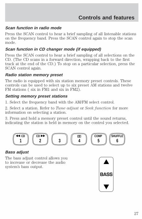
Scan function in radio modePress the SCAN control to hear a brief sampling of all listenable stationson the frequency band. Press the SCAN control again to stop the scanmode.
Scan function in CD changer mode (if equipped)Press the SCAN control to hear a brief sampling of all selections on theCD. (The CD scans in a forward direction, wrapping back to the firsttrack at the end of the CD.) To stop on a particular selection, press theSCAN control again.
Radio station memory presetThe radio is equipped with six station memory preset controls. Thesecontrols can be used to select up to six preset AM stations and twelveFM stations ( six in FM1 and six in FM2).
Setting memory preset stations1. Select the frequency band with the AM/FM select control.
2. Select a station. Refer to Tune adjust or Seek function for moreinformation on selecting a station.
3. Press and hold a memory preset control until the sound returns,indicating the station is held in memory on the control you selected.
Bass adjustThe bass adjust control allows youto increase or decrease the audiosystem’s bass output.
SHUFFLECOMPCDCD
321 4 5 6
BASS
Controls and features
27
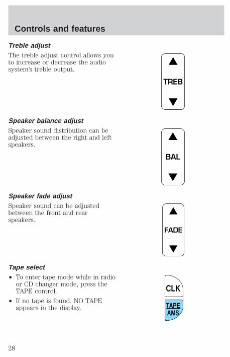
Treble adjustThe treble adjust control allows youto increase or decrease the audiosystem’s treble output.
Speaker balance adjustSpeaker sound distribution can beadjusted between the right and leftspeakers.
Speaker fade adjustSpeaker sound can be adjustedbetween the front and rearspeakers.
Tape select• To enter tape mode while in radio
or CD changer mode, press theTAPE control.
• If no tape is found, NO TAPEappears in the display.
TREB
BAL
FADE
TAPEAMS
CLK
Controls and features
28

Automatic Music SearchThe Automatic Music Search featureallows you to quickly locate thebeginning of the tape selectionbeing played or to skip to the nextselection.
To activate the feature, momentarilydepress the TAPE AMS button.Then, press either REW (for the beginning of the current selection) orFF (to advance to the next selection). The tape deck stops and returnsto play mode when the AMS circuit senses a blank section on the tape.
In order to ensure proper operation of the AMS feature, the tape MUSThave a blank section of at least 4 seconds duration between programs.
CD changer select (if equipped)• To enter CD changer mode while
in radio or tape mode, press theCD control.
RewindThe rewind control works in tape and CD changer (if equipped) modes.
To rewind in tape mode, press theSIDE/REW control.
Press the 1–2/FF control to stoprewinding the tape.
To rewind in CD changer mode,press the CD control (preset 1).
Press the control again to deactivaterewind mode.
TAPEAMS
CLK
AMFM
CD
SIDEREW FF
1 - 2
SIDEREW FF
1 - 2
CD
1
Controls and features
29
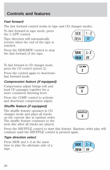
Fast forwardThe fast forward control works in tape and CD changer modes.
To fast forward in tape mode, pressthe 1–2/FF control.
Tape direction will automaticallyreverse when the end of the tape isreached.
Press the SIDE/REW control to stopthe fast forward of the tape.
To fast forward in CD changer mode,press the CD control (preset 2).
Press the control again to deactivatefast forward mode.
Compression feature (if equipped)Compression adjust brings soft andloud CD passages together for amore consistent listening level.
Press the COMP control to activateand deactivate compression adjust.
Shuffle feature (if equipped)The shuffle feature operates in CDchanger mode and plays all trackson the current disc in random order.The shuffle feature continues to thenext disc after all tracks are played.
Press the SHUFFLE control to start this feature. Random order play willcontinue until the SHUFFLE control is pressed again.
Tape direction selectPress SIDE and 1–2 at the sametime to play the alternate side of atape.
SIDEREW FF
1 - 2
SIDEREW FF
1 - 2
CD
2
COMP
5
SHUFFLE
6
SIDEREW FF
1 - 2
Controls and features
30
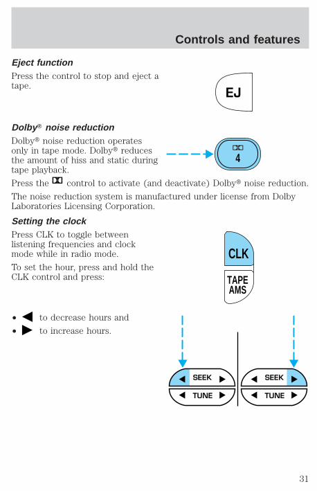
Eject functionPress the control to stop and eject atape.
Dolby T noise reductionDolbyt noise reduction operatesonly in tape mode. Dolbyt reducesthe amount of hiss and static duringtape playback.
Press the control to activate (and deactivate) Dolbyt noise reduction.
The noise reduction system is manufactured under license from DolbyLaboratories Licensing Corporation.
Setting the clockPress CLK to toggle betweenlistening frequencies and clockmode while in radio mode.
To set the hour, press and hold theCLK control and press:
• to decrease hours and
• to increase hours.
EJ
4
TAPEAMS
CLK
SEEK SEEK
TUNE TUNE
Controls and features
31
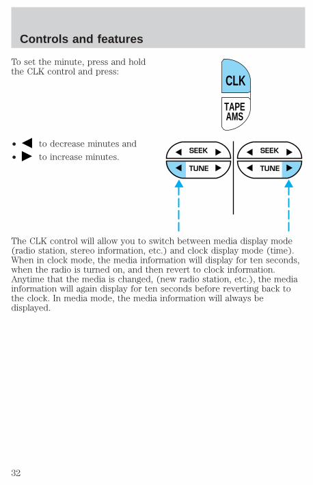
To set the minute, press and holdthe CLK control and press:
• to decrease minutes and
• to increase minutes.
The CLK control will allow you to switch between media display mode(radio station, stereo information, etc.) and clock display mode (time).When in clock mode, the media information will display for ten seconds,when the radio is turned on, and then revert to clock information.Anytime that the media is changed, (new radio station, etc.), the mediainformation will again display for ten seconds before reverting back tothe clock. In media mode, the media information will always bedisplayed.
TAPEAMS
CLK
SEEK
TUNE
SEEK
TUNE
Controls and features
32
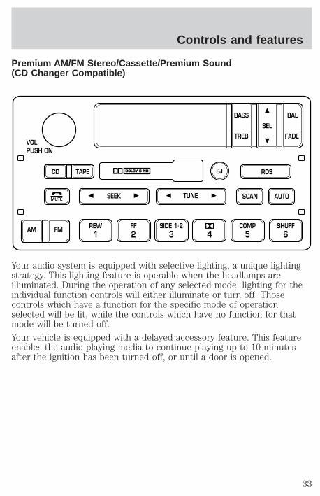
Premium AM/FM Stereo/Cassette/Premium Sound(CD Changer Compatible)
Your audio system is equipped with selective lighting, a unique lightingstrategy. This lighting feature is operable when the headlamps areilluminated. During the operation of any selected mode, lighting for theindividual function controls will either illuminate or turn off. Thosecontrols which have a function for the specific mode of operationselected will be lit, while the controls which have no function for thatmode will be turned off.
Your vehicle is equipped with a delayed accessory feature. This featureenables the audio playing media to continue playing up to 10 minutesafter the ignition has been turned off, or until a door is opened.
SCAN
VOLPUSH ON
REW1
FF2
SIDE 1.23 4
COMP5
SHUFF6
AUTOTUNESEEK
SEL
BAL
FADE
MUTE
FMAM
EJ
BASS
TREB
CD TAPE RDS
Controls and features
33

Volume/power controlPress the control to turn the audiosystem on or off.
Turn the control to raise or lowervolume.
If the volume is set above a certain level and the ignition is turned off,the volume will come back on at a “nominal” listening level when theignition switch is turned back on.
Speed sensitive volume (if equipped)With this feature, radio volume changes automatically and slightly withvehicle speed to compensate for road and wind noise.
The recommended level for speed sensitive volume is from level 1through level 3. Level 0 turns the speed sensitive volume off and level 7is the maximum setting.
With the radio on, press and holdthe volume control for five seconds,until the display reads SPEEDVOL#, then press:
VOLPUSH ON
VOLPUSH ON
VOLPUSH ON
Controls and features
34
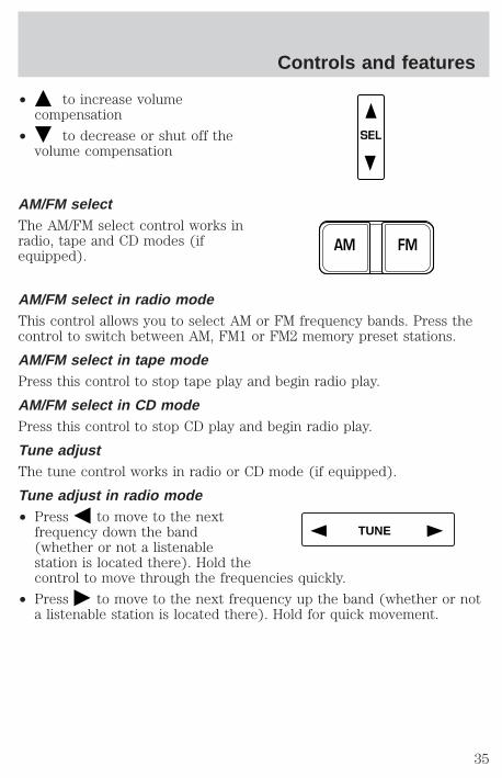
• to increase volumecompensation
• to decrease or shut off thevolume compensation
AM/FM selectThe AM/FM select control works inradio, tape and CD modes (ifequipped).
AM/FM select in radio modeThis control allows you to select AM or FM frequency bands. Press thecontrol to switch between AM, FM1 or FM2 memory preset stations.
AM/FM select in tape modePress this control to stop tape play and begin radio play.
AM/FM select in CD modePress this control to stop CD play and begin radio play.
Tune adjustThe tune control works in radio or CD mode (if equipped).
Tune adjust in radio mode• Press to move to the next
frequency down the band(whether or not a listenablestation is located there). Hold thecontrol to move through the frequencies quickly.
• Press to move to the next frequency up the band (whether or nota listenable station is located there). Hold for quick movement.
SEL
FMAM
TUNE
Controls and features
35
Tune adjust for CD changer• Press to select the previous
disc in the CD changer. (Play willbegin on the first track of thedisc unless the CD changer is inshuffle mode.) Refer to Shuffle feature for more information. Hold thecontrol to continue reversing through the discs.
• Press to select the next disc in the CD changer. Hold the controlto fast-forward through the remaining discs.
Seek functionThe seek function control works in radio, tape or CD mode (ifequipped).
Seek function in radio mode• Press to find the next
listenable station down thefrequency band.
• Press to find the nextlistenable station up the frequency band.
Seek function in tape mode• Press to listen to the previous selection on the tape or return to
the beginning of the current selection.
• Press to listen to the next selection on the tape.
Seek function for CD changer• Press to seek to the previous
track of the current disc. If aselection has been playing forthree seconds or more and youpress , the CD changer will replay that selection from thebeginning.
• Press to seek forward to the next track of the current disc. Afterthe last track has been completed, the first track of the current discwill automatically replay.
TUNE
SEEK
SEEK
Controls and features
36

Scan functionThe scan function works in radio,tape or CD mode (if equipped).
Scan function in radio modePress the SCAN control to hear a brief sampling of all listenable stationson the frequency band. Press the SCAN control again to stop the scanmode.
Scan function in tape modePress the SCAN control to hear a short sampling of all selections on thetape. (The tape scans in a forward direction. At the end of the tape’sfirst side, direction automatically reverses to the opposite side of thetape.) To stop on a particular selection, press the control again.
Scan function in CD modePress the SCAN control to hear a short sampling of all selections on theCD. (The CD scans in a forward direction, wrapping back to the firsttrack at the end of the CD.) To stop on a particular selection, press thecontrol again.
Radio station memory presetThe radio is equipped with six station memory preset controls. Thesecontrols can be used to select up to six preset AM stations and twelveFM stations (six in FM1 and six in FM2).
Setting memory preset stations1. Select the frequency band with the AM/FM select control.
2. Select a station. Refer to Tune adjust or Seek function for moreinformation on selecting a station.
3. Press and hold a memory preset control until the sound returns,indicating the station is held in memory on the control you selected.
SCAN
REW1
FF2
SIDE 1.23 4
COMP5
SHUFF6
Controls and features
37
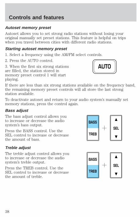
Autoset memory presetAutoset allows you to set strong radio stations without losing youroriginal manually set preset stations. This feature is helpful on tripswhen you travel between cities with different radio stations.
Starting autoset memory preset1. Select a frequency using the AM/FM select controls.
2. Press the AUTO control.
3. When the first six strong stationsare filled, the station stored inmemory preset control 1 will startplaying.
If there are less than six strong stations available on the frequency band,the remaining memory preset controls will all store the last strongstation available.
To deactivate autoset and return to your audio system’s manually setmemory stations, press the control again.
Bass adjustThe bass adjust control allows youto increase or decrease the audiosystem’s bass output.
Press the BASS control. Use theSEL control to increase or decreasethe amount of bass.
Treble adjustThe treble adjust control allows youto increase or decrease the audiosystem’s treble output.
Press the TREB control. Use theSEL control to increase or decreasethe amount of treble.
AUTO
SEL
BASS
TREB
SEL
BASS
TREB
Controls and features
38
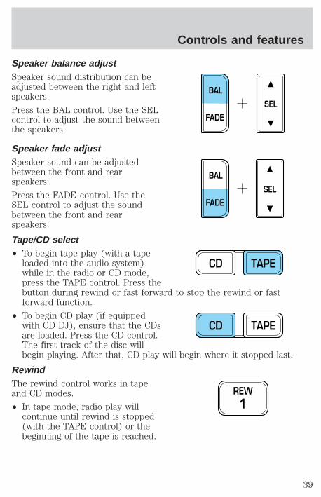
Speaker balance adjustSpeaker sound distribution can beadjusted between the right and leftspeakers.
Press the BAL control. Use the SELcontrol to adjust the sound betweenthe speakers.
Speaker fade adjustSpeaker sound can be adjustedbetween the front and rearspeakers.
Press the FADE control. Use theSEL control to adjust the soundbetween the front and rearspeakers.
Tape/CD select• To begin tape play (with a tape
loaded into the audio system)while in the radio or CD mode,press the TAPE control. Press thebutton during rewind or fast forward to stop the rewind or fastforward function.
• To begin CD play (if equippedwith CD DJ), ensure that the CDsare loaded. Press the CD control.The first track of the disc willbegin playing. After that, CD play will begin where it stopped last.
RewindThe rewind control works in tapeand CD modes.
• In tape mode, radio play willcontinue until rewind is stopped(with the TAPE control) or thebeginning of the tape is reached.
SEL
BAL
FADE
SEL
BAL
FADE
CD TAPE
CD TAPE
REW1
Controls and features
39
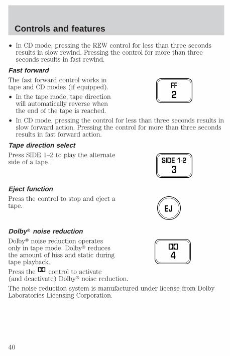
• In CD mode, pressing the REW control for less than three secondsresults in slow rewind. Pressing the control for more than threeseconds results in fast rewind.
Fast forwardThe fast forward control works intape and CD modes (if equipped).
• In the tape mode, tape directionwill automatically reverse whenthe end of the tape is reached.
• In CD mode, pressing the control for less than three seconds results inslow forward action. Pressing the control for more than three secondsresults in fast forward action.
Tape direction selectPress SIDE 1–2 to play the alternateside of a tape.
Eject functionPress the control to stop and eject atape.
Dolby T noise reductionDolbyt noise reduction operatesonly in tape mode. Dolbyt reducesthe amount of hiss and static duringtape playback.
Press the control to activate(and deactivate) Dolbyt noise reduction.
The noise reduction system is manufactured under license from DolbyLaboratories Licensing Corporation.
FF2
SIDE 1-23
EJ
4
Controls and features
40
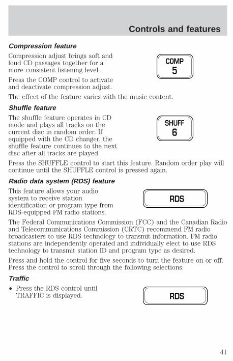
Compression featureCompression adjust brings soft andloud CD passages together for amore consistent listening level.
Press the COMP control to activateand deactivate compression adjust.
The effect of the feature varies with the music content.
Shuffle featureThe shuffle feature operates in CDmode and plays all tracks on thecurrent disc in random order. Ifequipped with the CD changer, theshuffle feature continues to the nextdisc after all tracks are played.
Press the SHUFFLE control to start this feature. Random order play willcontinue until the SHUFFLE control is pressed again.
Radio data system (RDS) featureThis feature allows your audiosystem to receive stationidentification or program type fromRDS-equipped FM radio stations.
The Federal Communications Commission (FCC) and the Canadian Radioand Telecommunications Commission (CRTC) recommend FM radiobroadcasters to use RDS technology to transmit information. FM radiostations are independently operated and individually elect to use RDStechnology to transmit station ID and program type as desired.
Press and hold the control for five seconds to turn the feature on or off.Press the control to scroll through the following selections:
Traffic• Press the RDS control until
TRAFFIC is displayed.
COMP5
SHUFF6
RDS
RDS
Controls and features
41
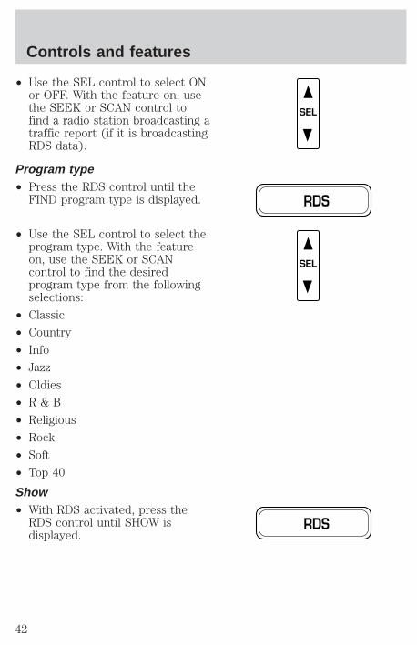
• Use the SEL control to select ONor OFF. With the feature on, usethe SEEK or SCAN control tofind a radio station broadcasting atraffic report (if it is broadcastingRDS data).
Program type• Press the RDS control until the
FIND program type is displayed.
• Use the SEL control to select theprogram type. With the featureon, use the SEEK or SCANcontrol to find the desiredprogram type from the followingselections:
• Classic
• Country
• Info
• Jazz
• Oldies
• R & B
• Religious
• Rock
• Soft
• Top 40
Show• With RDS activated, press the
RDS control until SHOW isdisplayed.
SEL
RDS
SEL
RDS
Controls and features
42

• Use the SEL control to selectTYPE, NAME or NONE.
RDS clock featureRefer to Setting the clock for information.
Mute modePress the control to mute theplaying media. Press the controlagain to return to the playing media.
Setting the clock with radio data system (RDS) featurePress the RDS control until CLOCKHOUR or CLOCK MINUTE isdisplayed.
Use the SEL control to manually setthe time.
• Press to increasehours/minutes.
• Press to decreasehours/minutes.
SEL
MUTE
RDS
SEL
Controls and features
43
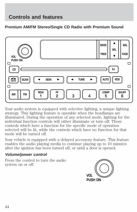
Premium AM/FM Stereo/Single CD Radio with Premium Sound
Your audio system is equipped with selective lighting, a unique lightingstrategy. This lighting feature is operable when the headlamps areilluminated. During the operation of any selected mode, lighting for theindividual function controls will either illuminate or turn off. Thosecontrols which have a function for the specific mode of operationselected will be lit, while the controls which have no function for thatmode will be turned off.
Your vehicle is equipped with a delayed accessory feature. This featureenables the audio playing media to continue playing up to 10 minutesafter the ignition has been turned off, or until a door is opened.
Volume/power controlPress the control to turn the audiosystem on or off.
CD
SCAN
VOLPUSH ON
REW1
FF2 3 4
COMP5
SHUFF6
RDS
EJ
AUTOTUNESEEK
SEL
BAL
FADE
MUTE
FMAM
BASS
TREB
VOLPUSH ON
Controls and features
44
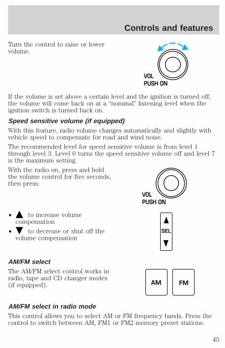
Turn the control to raise or lowervolume.
If the volume is set above a certain level and the ignition is turned off,the volume will come back on at a “nominal” listening level when theignition switch is turned back on.
Speed sensitive volume (if equipped)With this feature, radio volume changes automatically and slightly withvehicle speed to compensate for road and wind noise.
The recommended level for speed sensitive volume is from level 1through level 3. Level 0 turns the speed sensitive volume off and level 7is the maximum setting.
With the radio on, press and holdthe volume control for five seconds,then press:
• to increase volumecompensation
• to decrease or shut off thevolume compensation
AM/FM selectThe AM/FM select control works inradio, tape and CD changer modes(if equipped).
AM/FM select in radio modeThis control allows you to select AM or FM frequency bands. Press thecontrol to switch between AM, FM1 or FM2 memory preset stations.
VOLPUSH ON
VOLPUSH ON
SEL
AM FM
Controls and features
45
AM/FM select in tape modePress this control to stop tape play and begin radio play.
AM/FM select in CD changer mode (if equipped)Press this control to stop CD play and begin radio play.
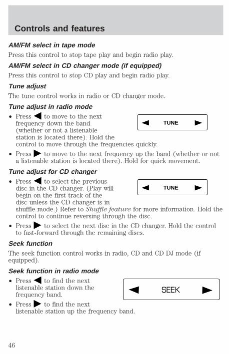
Tune adjustThe tune control works in radio or CD changer mode.
Tune adjust in radio mode• Press to move to the next
frequency down the band(whether or not a listenablestation is located there). Hold thecontrol to move through the frequencies quickly.
• Press to move to the next frequency up the band (whether or nota listenable station is located there). Hold for quick movement.
Tune adjust for CD changer• Press to select the previous
disc in the CD changer. (Play willbegin on the first track of thedisc unless the CD changer is inshuffle mode.) Refer to Shuffle feature for more information. Hold thecontrol to continue reversing through the disc.
• Press to select the next disc in the CD changer. Hold the controlto fast-forward through the remaining discs.
Seek functionThe seek function control works in radio, CD and CD DJ mode (ifequipped).
Seek function in radio mode• Press to find the next
listenable station down thefrequency band.
• Press to find the nextlistenable station up the frequency band.
TUNE
TUNE
SEEK
Controls and features
46
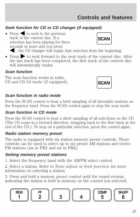
Seek function for CD or CD changer (if equipped)• Press to seek to the previous
track of the current disc. If aselection has been playing for threeseconds or more and you press
, the CD changer will replay that selection from the beginning.
• Press to seek forward to the next track of the current disc. Afterthe last track has been completed, the first track of the current discwill automatically replay.
Scan functionThe scan function works in radio,CD and CD DJ mode (if equipped).
Scan function in radio modePress the SCAN control to hear a brief sampling of all listenable stations onthe frequency band. Press the SCAN control again to stop the scan mode.
Scan function in CD modePress the SCAN control to hear a short sampling of all selections on the CD(The CD scans in a forward direction, wrapping back to the first track at theend of the CD.). To stop on a particular selection, press the control again.
Radio station memory presetThe radio is equipped with six station memory preset controls. Thesecontrols can be used to select up to six preset AM stations and twelveFM stations (six in FM1 and six in FM2).
Setting memory preset stations1. Select the frequency band with the AM/FM select control.
2. Select a station. Refer to Tune adjust or Seek function for moreinformation on selecting a station.
3. Press and hold a memory preset control until the sound returns,indicating the station is held in memory on the control you selected.
SCAN
SCAN
REW1
FF2 3 4
COMP5
SHUFF6
Controls and features
47
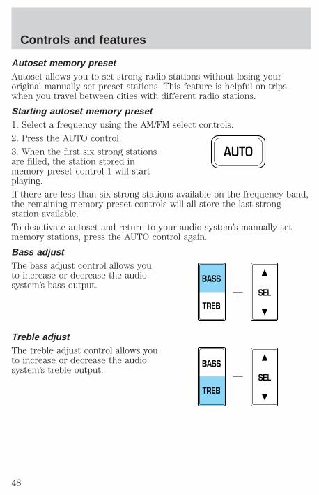
Autoset memory presetAutoset allows you to set strong radio stations without losing youroriginal manually set preset stations. This feature is helpful on tripswhen you travel between cities with different radio stations.
Starting autoset memory preset1. Select a frequency using the AM/FM select controls.
2. Press the AUTO control.
3. When the first six strong stationsare filled, the station stored inmemory preset control 1 will startplaying.
If there are less than six strong stations available on the frequency band,the remaining memory preset controls will all store the last strongstation available.
To deactivate autoset and return to your audio system’s manually setmemory stations, press the AUTO control again.
Bass adjustThe bass adjust control allows youto increase or decrease the audiosystem’s bass output.
Treble adjustThe treble adjust control allows youto increase or decrease the audiosystem’s treble output.
AUTO
SEL
BASS
TREB
SEL
BASS
TREB
Controls and features
48

Speaker balance adjustSpeaker sound distribution can beadjusted between the right and leftspeakers.
Speaker fade adjustSpeaker sound can be adjustedbetween the front and rearspeakers.
CD selectTo begin CD play (if CD[s] are loaded), press the CD control. The firsttrack of the disc will begin playing. After that, CD play will begin whereit stopped last.
RewindThe rewind control works in CDmode.
• In CD mode, pressing the REWcontrol for less than threeseconds results in slow rewind.Pressing the control for more than three seconds results in fastrewind.
Fast forwardThe fast forward control works inCD mode.
• In CD mode, pressing the controlfor less than three secondsresults in slow forward action. Pressing the control for more thanthree seconds results in fast forward action.
SEL
BAL
FADE
SEL
BAL
FADE
REW1
FF2
Controls and features
49

Eject functionPress the control to stop and eject atape or CD.
Compression feature (if equipped)Compression adjust brings soft andloud CD passages together for amore consistent listening level.
Press the COMP control to activateand deactivate compression adjust.
Shuffle feature (if equipped)The shuffle feature operates in CDchanger mode and plays all trackson the current disc in random order.The shuffle feature continues to thenext disc after all tracks are played.
Press the SHUFFLE control to start this feature. Random order play willcontinue until the SHUFFLE control is pressed again.
Radio data system (RDS) featureThis feature allows your audiosystem to receive stationidentification or program type fromRDS-equipped FM radio station.
The Federal Communications Commission (FCC) and the Canadian Radioand Telecommunications Commission (CRTC) recommend FM radiobroadcasters to use RDS technology to transmit information. FM radiostations are independently operated and individually elect to use RDStechnology to transmit station ID and program type as desired.
Press and hold the control for five seconds to turn the feature on or off.Press the control to scroll through the following sections:
Traffic• Press the RDS control until
TRAFFIC is displayed.
EJ
COMP5
SHUFF6
RDS
RDS
Controls and features
50
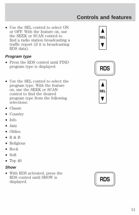
• Use the SEL control to select ONor OFF. With the feature on, usethe SEEK or SCAN control tofind a radio station broadcasting atraffic report (if it is broadcastingRDS data).
Program type• Press the RDS control until FIND
program type is displayed.
• Use the SEL control to select theprogram type. With the featureon, use the SEEK or SCANcontrol to find the desiredprogram type from the followingselections:
• Classic
• Country
• Info
• Jazz
• Oldies
• R & B
• Religious
• Rock
• Soft
• Top 40
Show• With RDS activated, press the
RDS control until SHOW isdisplayed.
SEL
RDS
SEL
RDS
Controls and features
51
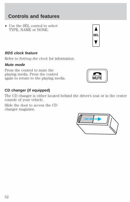
• Use the SEL control to selectTYPE, NAME or NONE.
RDS clock featureRefer to Setting the clock for information.
Mute modePress the control to mute theplaying media. Press the controlagain to return to the playing media.
CD changer (if equipped)The CD changer is either located behind the driver’s seat or in the centerconsole of your vehicle.
Slide the door to access the CDchanger magazine.
SEL
MUTE
Controls and features
52
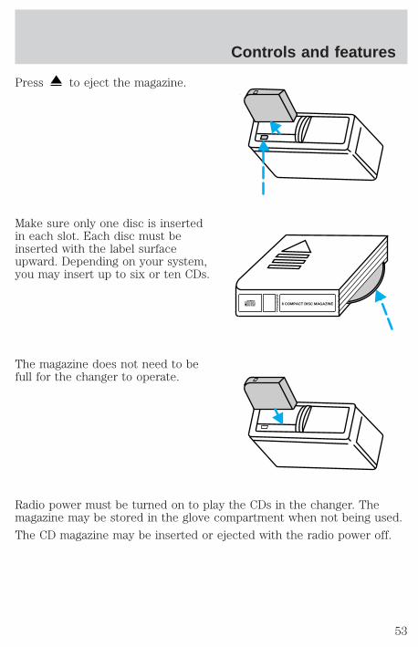
Press to eject the magazine.
Make sure only one disc is insertedin each slot. Each disc must beinserted with the label surfaceupward. Depending on your system,you may insert up to six or ten CDs.
The magazine does not need to befull for the changer to operate.
Radio power must be turned on to play the CDs in the changer. Themagazine may be stored in the glove compartment when not being used.
The CD magazine may be inserted or ejected with the radio power off.
654321
6 COMPACT DISC MAGAZINECOMPACT
DIGITAL AUDIO
Controls and features
53
Troubleshooting the CD changer (if equipped)
The laser beam used in the compact disc player is harmful to theeyes. Do not attempt to disassemble the case.
If sound skips:
• You may be traveling on a rough road, playing badly scratched discs orthe disc may be dirty. Skipping will not scratch the discs or damagethe player.
If your changer does not work, it may be that:
• A disc is already loaded where you want to insert a disc.
• The disc is inserted with the label surface downward.
• The disc is dusty or defective.
• The player’s internal temperature is above 60°C (140°F). Allow theplayer to cool down before operating.
• A disc with format and dimensions not within industry standards isinserted.
Cleaning compact discsInspect all discs for contamination before playing. If necessary, cleandiscs only with an approved CD cleaner and wipe from the center out tothe edge. Do not use circular motion.
CD and CD changer care• Handle discs by their edges only. Never touch the playing surface.
• Do not expose discs to direct sunlight or heat sources for extendedperiods of time.
• Do not insert more than one disc into each slot of the CD changermagazine.
Cleaning cassette player (if equipped)Clean the tape player head with a cassette cleaning cartridge after ten totwelve hours of play in order to maintain the best sound and operation.
Cassette and cassette player care• Use only cassettes that are 90 minutes long or less.
Controls and features
54
• Do not expose tapes to direct sunlight, high humidity, extreme heat orextreme cold. Allow tapes that may have been exposed to extremetemperatures to reach a moderate temperature before playing.
• Tighten very loose tapes by inserting a finger or pencil into the holeand turning the hub.
• Remove loose labels before inserting tapes.
• Do not leave tapes in the cassette player for a long time when notbeing played.
Radio frequency informationThe Federal Communications Commission (FCC) and the Canadian Radioand Telecommunications Commission(CRTC) establish the frequenciesAM and FM stations may use for their broadcasts. Allowable frequenciesare:
AM 530, 540–1600, 1610 kHz
FM 87.9, 88.1–107.1, 107.9 MHz
Not all frequencies are used in a given area.
Radio reception factorsThree factors can affect radio reception:
• Distance/strength. The further an FM signal travels, the weaker it is.The listenable range of the average FM station is approximately 40 km(24 miles). This range can be affected by “signal modulation.” Signalmodulation is a process radio stations use to increase theirstrength/volume relative to other stations.
• Terrain. Hills, mountains and tall buildings between your vehicle’santenna and the radio station signal can cause FM reception problems.Static can be caused on AM stations by power lines, electric fences,traffic lights and thunderstorms. Moving away from an interferingstructure (out of its “shadow”) returns your reception to normal.
• Station overload. Weak signals are sometimes captured by strongersignals when you pass a broadcast tower. A stronger signal maytemporarily overtake a weaker signal and play while the weak stationfrequency is displayed.
The audio system automatically switches to single channel reception if itwill improve the reception of a station normally received in stereo.
Controls and features
55
Audio system warranties and serviceRefer to the “Warranty Guide” for audio system warranty information.
If service is necessary, see your dealer or a qualified technician.
CLIMATE CONTROL SYSTEM
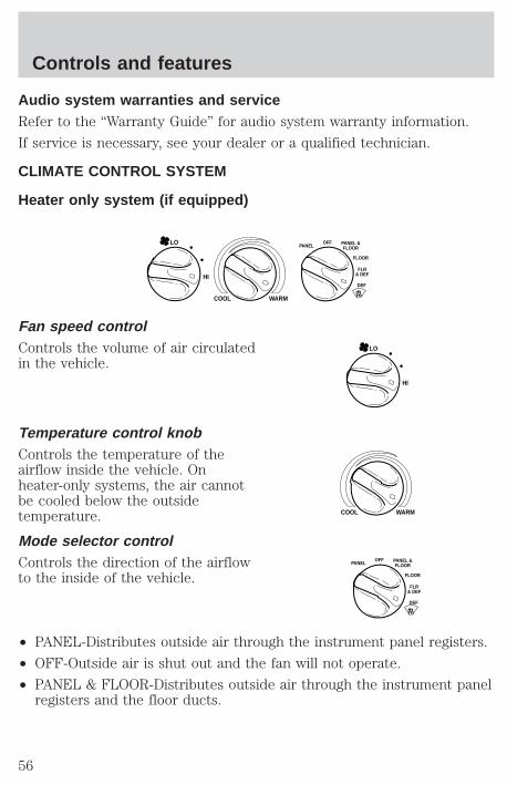
Heater only system (if equipped)
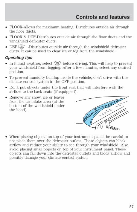
Fan speed controlControls the volume of air circulatedin the vehicle.
Temperature control knobControls the temperature of theairflow inside the vehicle. Onheater-only systems, the air cannotbe cooled below the outsidetemperature.
Mode selector controlControls the direction of the airflowto the inside of the vehicle.
• PANEL-Distributes outside air through the instrument panel registers.
• OFF-Outside air is shut out and the fan will not operate.
• PANEL & FLOOR-Distributes outside air through the instrument panelregisters and the floor ducts.
HI
COOL WARM
OFFPANEL
FLOOR
DEF
FLR& DEF
PANEL &FLOOR
LO
HI
LO
COOL WARM
OFFPANEL
FLOOR
DEF
FLR& DEF
PANEL &FLOOR
Controls and features
56
• FLOOR-Allows for maximum heating. Distributes outside air throughthe floor ducts.
• FLOOR & DEF-Distributes outside air through the floor ducts and thewindshield defroster ducts.
• DEF -Distributes outside air through the windshield defrosterducts. It can be used to clear ice or fog from the windshield.
Operating tips• In humid weather, select before driving. This will help to prevent
your windshield from fogging. After a few minutes, select any desiredposition.
• To prevent humidity buildup inside the vehicle, don’t drive with theclimate control system in the OFF position.
• Don’t put objects under the front seat that will interfere with theairflow to the back seats (if equipped).
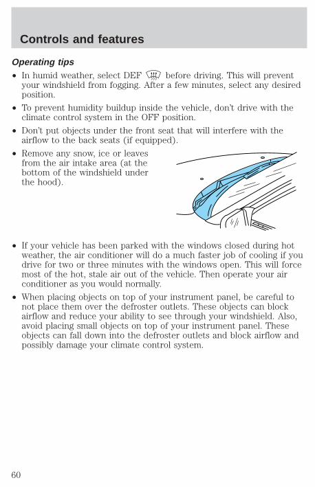
• Remove any snow, ice or leavesfrom the air intake area (at thebottom of the windshield underthe hood).
• When placing objects on top of your instrument panel, be careful tonot place them over the defroster outlets. These objects can blockairflow and reduce your ability to see through your windshield. Also,avoid placing small objects on top of your instrument panel. Theseobjects can fall down into the defroster outlets and block airflow andpossibly damage your climate control system.
Controls and features
57
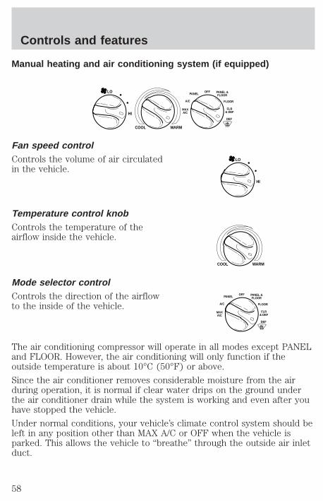
Manual heating and air conditioning system (if equipped)
Fan speed controlControls the volume of air circulatedin the vehicle.
Temperature control knobControls the temperature of theairflow inside the vehicle.
Mode selector controlControls the direction of the airflowto the inside of the vehicle.
The air conditioning compressor will operate in all modes except PANELand FLOOR. However, the air conditioning will only function if theoutside temperature is about 10°C (50°F) or above.
Since the air conditioner removes considerable moisture from the airduring operation, it is normal if clear water drips on the ground underthe air conditioner drain while the system is working and even after youhave stopped the vehicle.
Under normal conditions, your vehicle’s climate control system should beleft in any position other than MAX A/C or OFF when the vehicle isparked. This allows the vehicle to “breathe” through the outside air inletduct.
HI
COOL WARM
OFFPANEL
A/C FLOOR
DEF
FLR& DEF
MAXA/C
PANEL &FLOOR
LO
HI
LO
COOL WARM
OFFPANEL
A/C FLOOR
DEF
FLR& DEF
MAXA/C
PANEL &FLOOR
Controls and features
58
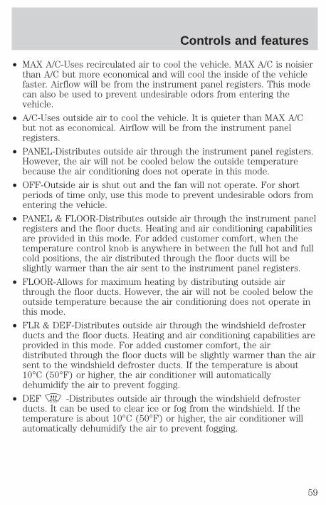
• MAX A/C-Uses recirculated air to cool the vehicle. MAX A/C is noisierthan A/C but more economical and will cool the inside of the vehiclefaster. Airflow will be from the instrument panel registers. This modecan also be used to prevent undesirable odors from entering thevehicle.
• A/C-Uses outside air to cool the vehicle. It is quieter than MAX A/Cbut not as economical. Airflow will be from the instrument panelregisters.
• PANEL-Distributes outside air through the instrument panel registers.However, the air will not be cooled below the outside temperaturebecause the air conditioning does not operate in this mode.
• OFF-Outside air is shut out and the fan will not operate. For shortperiods of time only, use this mode to prevent undesirable odors fromentering the vehicle.
• PANEL & FLOOR-Distributes outside air through the instrument panelregisters and the floor ducts. Heating and air conditioning capabilitiesare provided in this mode. For added customer comfort, when thetemperature control knob is anywhere in between the full hot and fullcold positions, the air distributed through the floor ducts will beslightly warmer than the air sent to the instrument panel registers.
• FLOOR-Allows for maximum heating by distributing outside airthrough the floor ducts. However, the air will not be cooled below theoutside temperature because the air conditioning does not operate inthis mode.
• FLR & DEF-Distributes outside air through the windshield defrosterducts and the floor ducts. Heating and air conditioning capabilities areprovided in this mode. For added customer comfort, the airdistributed through the floor ducts will be slightly warmer than the airsent to the windshield defroster ducts. If the temperature is about10°C (50°F) or higher, the air conditioner will automaticallydehumidify the air to prevent fogging.
• DEF -Distributes outside air through the windshield defrosterducts. It can be used to clear ice or fog from the windshield. If thetemperature is about 10°C (50°F) or higher, the air conditioner willautomatically dehumidify the air to prevent fogging.
Controls and features
59
Operating tips• In humid weather, select DEF before driving. This will prevent
your windshield from fogging. After a few minutes, select any desiredposition.
• To prevent humidity buildup inside the vehicle, don’t drive with theclimate control system in the OFF position.
• Don’t put objects under the front seat that will interfere with theairflow to the back seats (if equipped).
• Remove any snow, ice or leavesfrom the air intake area (at thebottom of the windshield underthe hood).
• If your vehicle has been parked with the windows closed during hotweather, the air conditioner will do a much faster job of cooling if youdrive for two or three minutes with the windows open. This will forcemost of the hot, stale air out of the vehicle. Then operate your airconditioner as you would normally.
• When placing objects on top of your instrument panel, be careful tonot place them over the defroster outlets. These objects can blockairflow and reduce your ability to see through your windshield. Also,avoid placing small objects on top of your instrument panel. Theseobjects can fall down into the defroster outlets and block airflow andpossibly damage your climate control system.
Controls and features
60
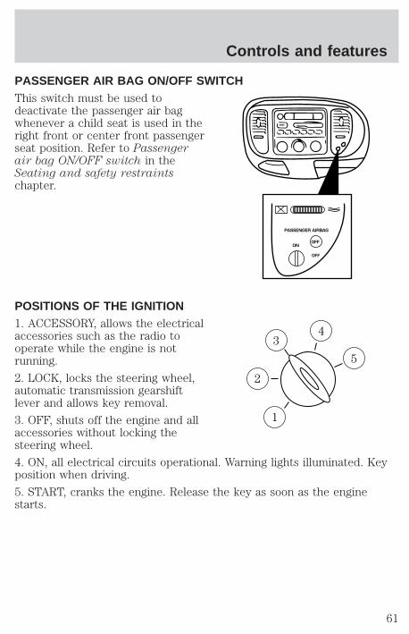
PASSENGER AIR BAG ON/OFF SWITCHThis switch must be used todeactivate the passenger air bagwhenever a child seat is used in theright front or center front passengerseat position. Refer to Passengerair bag ON/OFF switch in theSeating and safety restraintschapter.
POSITIONS OF THE IGNITION1. ACCESSORY, allows the electricalaccessories such as the radio tooperate while the engine is notrunning.
2. LOCK, locks the steering wheel,automatic transmission gearshiftlever and allows key removal.
3. OFF, shuts off the engine and allaccessories without locking thesteering wheel.
4. ON, all electrical circuits operational. Warning lights illuminated. Keyposition when driving.
5. START, cranks the engine. Release the key as soon as the enginestarts.
PASSENGER AIRBAG
ON
OFF
OFF
3
1
2
5
4
Controls and features
61
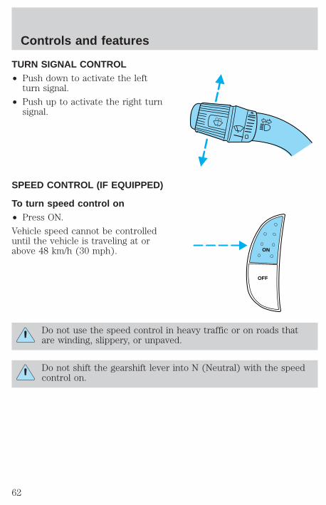
TURN SIGNAL CONTROL• Push down to activate the left
turn signal.
• Push up to activate the right turnsignal.
SPEED CONTROL (IF EQUIPPED)
To turn speed control on• Press ON.
Vehicle speed cannot be controlleduntil the vehicle is traveling at orabove 48 km/h (30 mph).
Do not use the speed control in heavy traffic or on roads thatare winding, slippery, or unpaved.
Do not shift the gearshift lever into N (Neutral) with the speedcontrol on.
ON
OFF
Controls and features
62
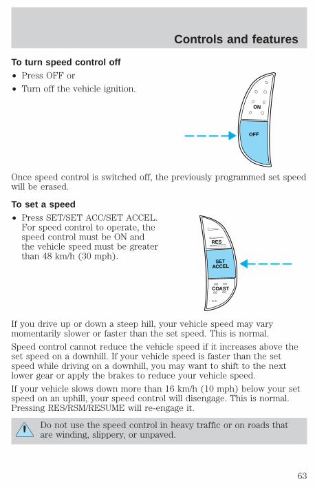
To turn speed control off• Press OFF or
• Turn off the vehicle ignition.
Once speed control is switched off, the previously programmed set speedwill be erased.
To set a speed• Press SET/SET ACC/SET ACCEL.
For speed control to operate, thespeed control must be ON andthe vehicle speed must be greaterthan 48 km/h (30 mph).
If you drive up or down a steep hill, your vehicle speed may varymomentarily slower or faster than the set speed. This is normal.
Speed control cannot reduce the vehicle speed if it increases above theset speed on a downhill. If your vehicle speed is faster than the setspeed while driving on a downhill, you may want to shift to the nextlower gear or apply the brakes to reduce your vehicle speed.
If your vehicle slows down more than 16 km/h (10 mph) below your setspeed on an uphill, your speed control will disengage. This is normal.Pressing RES/RSM/RESUME will re-engage it.
Do not use the speed control in heavy traffic or on roads thatare winding, slippery, or unpaved.
ON
OFF
RES
SETACCEL
COAST
Controls and features
63
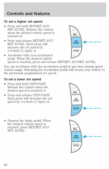
To set a higher set speed• Press and hold SET/SET ACC/
SET ACCEL. Release the controlwhen the desired vehicle speed isreached or
• Press and release SET/SET ACC/SET ACCEL. Each press willincrease the set speed by1.6 km/h (1 mph) or
• Accelerate with your acceleratorpedal. When the desired vehiclespeed is reached, press and release SET/SET ACC/SET ACCEL.
You can accelerate with the accelerator pedal at any time during speedcontrol usage. Releasing the accelerator pedal will return your vehicle tothe previously programmed set speed.
To set a lower set speed• Press and hold CST/COAST.
Release the control when thedesired speed is reached or
• Press and release CST/COAST.Each press will decrease the setspeed by 1.6 km/h (1 mph) or
• Depress the brake pedal. Whenthe desired vehicle speed isreached, press SET/SET ACC/SET ACCEL.
RES
SETACCEL
COAST
RES
SETACCEL
COAST
RES
SETACCEL
COAST
Controls and features
64
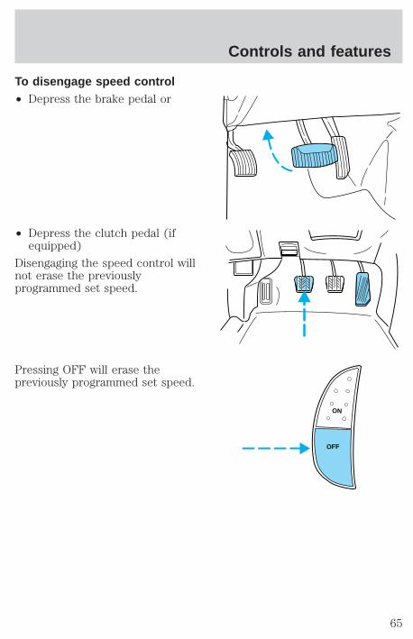
To disengage speed control• Depress the brake pedal or
• Depress the clutch pedal (ifequipped)
Disengaging the speed control willnot erase the previouslyprogrammed set speed.
Pressing OFF will erase thepreviously programmed set speed.
ON
OFF
Controls and features
65
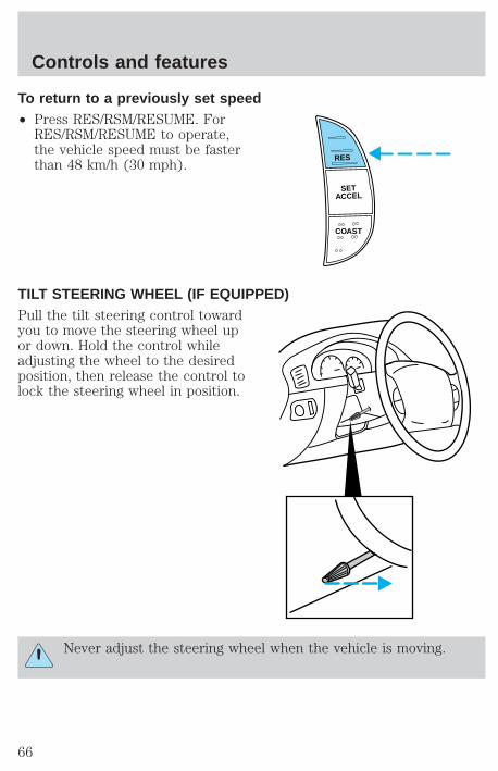
To return to a previously set speed• Press RES/RSM/RESUME. For
RES/RSM/RESUME to operate,the vehicle speed must be fasterthan 48 km/h (30 mph).
TILT STEERING WHEEL (IF EQUIPPED)Pull the tilt steering control towardyou to move the steering wheel upor down. Hold the control whileadjusting the wheel to the desiredposition, then release the control tolock the steering wheel in position.
Never adjust the steering wheel when the vehicle is moving.
RES
SETACCEL
COAST
Controls and features
66
HAZARD FLASHERFor information on the hazard flasher control, refer to Hazard flasher inthe Roadside emergencies chapter.
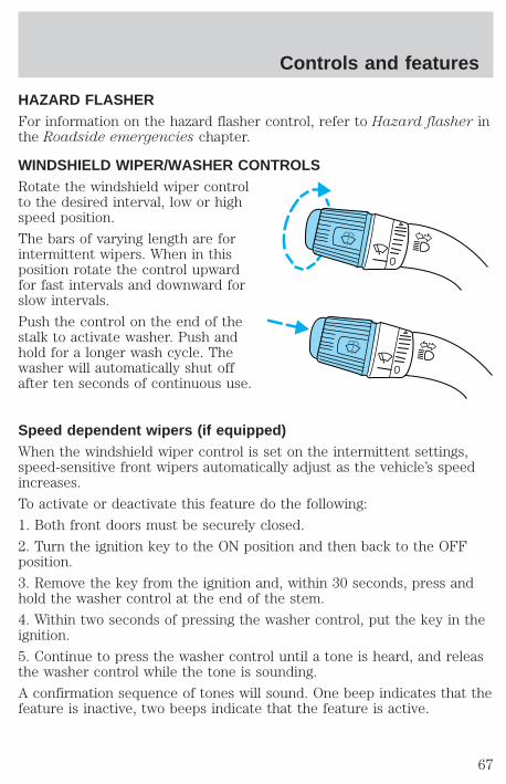
WINDSHIELD WIPER/WASHER CONTROLSRotate the windshield wiper controlto the desired interval, low or highspeed position.
The bars of varying length are forintermittent wipers. When in thisposition rotate the control upwardfor fast intervals and downward forslow intervals.
Push the control on the end of thestalk to activate washer. Push andhold for a longer wash cycle. Thewasher will automatically shut offafter ten seconds of continuous use.
Speed dependent wipers (if equipped)When the windshield wiper control is set on the intermittent settings,speed-sensitive front wipers automatically adjust as the vehicle’s speedincreases.
To activate or deactivate this feature do the following:
1. Both front doors must be securely closed.
2. Turn the ignition key to the ON position and then back to the OFFposition.
3. Remove the key from the ignition and, within 30 seconds, press andhold the washer control at the end of the stem.
4. Within two seconds of pressing the washer control, put the key in theignition.
5. Continue to press the washer control until a tone is heard, and releasthe washer control while the tone is sounding.
A confirmation sequence of tones will sound. One beep indicates that thefeature is inactive, two beeps indicate that the feature is active.
Controls and features
67
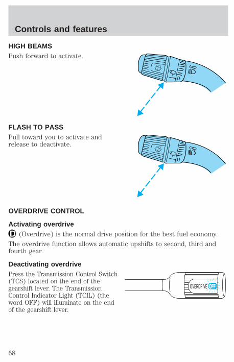
HIGH BEAMSPush forward to activate.
FLASH TO PASSPull toward you to activate andrelease to deactivate.
OVERDRIVE CONTROL
Activating overdrive(Overdrive) is the normal drive position for the best fuel economy.
The overdrive function allows automatic upshifts to second, third andfourth gear.
Deactivating overdrivePress the Transmission Control Switch(TCS) located on the end of thegearshift lever. The TransmissionControl Indicator Light (TCIL) (theword OFF) will illuminate on the endof the gearshift lever.
OVERDRIVE
Controls and features
68
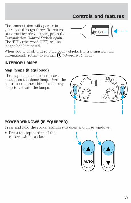
The transmission will operate ingears one through three. To returnto normal overdrive mode, press theTransmission Control Switch again.The TCIL (the word OFF) will nolonger be illuminated.
When you shut off and re-start your vehicle, the transmission willautomatically return to normal (Overdrive) mode.
INTERIOR LAMPS
Map lamps (if equipped)The map lamps and controls arelocated on the dome lamp. Press thecontrols on either side of each maplamp to activate the lamps.
POWER WINDOWS (IF EQUIPPED)Press and hold the rocker switches to open and close windows.
• Press the top portion of therocker switch to close.
OVERDRIVE OFF
AUTO
Controls and features
69
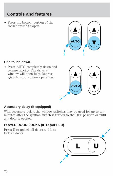
• Press the bottom portion of therocker switch to open.
One touch down• Press AUTO completely down and
release quickly. The driver’swindow will open fully. Depressagain to stop window operation.
Accessory delay (if equipped)With accessory delay, the window switches may be used for up to tenminutes after the ignition switch is turned to the OFF position or untilany door is opened.
POWER DOOR LOCKS (IF EQUIPPED)Press U to unlock all doors and L tolock all doors.
AUTO
AUTO
UL
Controls and features
70
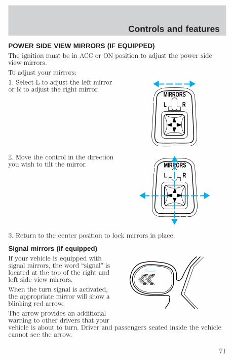
POWER SIDE VIEW MIRRORS (IF EQUIPPED)The ignition must be in ACC or ON position to adjust the power sideview mirrors.
To adjust your mirrors:
1. Select L to adjust the left mirroror R to adjust the right mirror.
2. Move the control in the directionyou wish to tilt the mirror.
3. Return to the center position to lock mirrors in place.
Signal mirrors (if equipped)If your vehicle is equipped withsignal mirrors, the word “signal” islocated at the top of the right andleft side view mirrors.
When the turn signal is activated,the appropriate mirror will show ablinking red arrow.
The arrow provides an additionalwarning to other drivers that yourvehicle is about to turn. Driver and passengers seated inside the vehiclecannot see the arrow.
MIRRORS
L R
MIRRORS
L R
Signal
Controls and features
71

Fold-away mirrorsPull the side mirrors in carefullywhen driving through a narrowspace, like an automatic car wash.
TAILGATE LOCK (IF EQUIPPED)Your vehicle is equipped with atailgate lock designed to preventtheft of the tailgate.
• Insert ignition key and turn to theright to engage lock.
• Turn ignition key to the left tounlock.
Controls and features
72
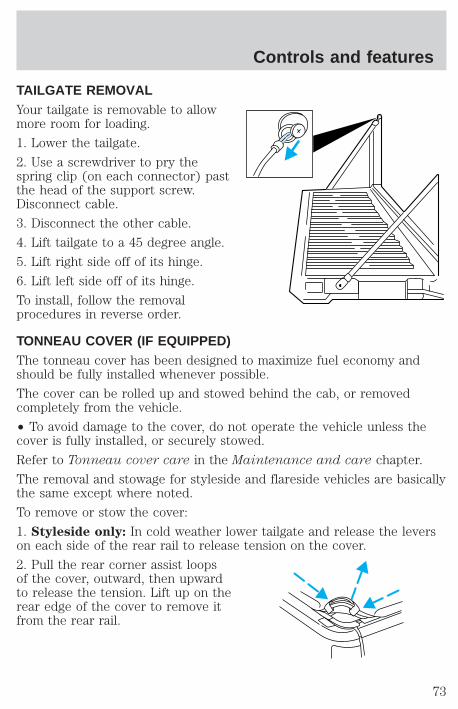
TAILGATE REMOVALYour tailgate is removable to allowmore room for loading.
1. Lower the tailgate.
2. Use a screwdriver to pry thespring clip (on each connector) pastthe head of the support screw.Disconnect cable.
3. Disconnect the other cable.
4. Lift tailgate to a 45 degree angle.
5. Lift right side off of its hinge.
6. Lift left side off of its hinge.
To install, follow the removalprocedures in reverse order.
TONNEAU COVER (IF EQUIPPED)The tonneau cover has been designed to maximize fuel economy andshould be fully installed whenever possible.
The cover can be rolled up and stowed behind the cab, or removedcompletely from the vehicle.
• To avoid damage to the cover, do not operate the vehicle unless thecover is fully installed, or securely stowed.
Refer to Tonneau cover care in the Maintenance and care chapter.
The removal and stowage for styleside and flareside vehicles are basicallythe same except where noted.
To remove or stow the cover:
1. Styleside only: In cold weather lower tailgate and release the leverson each side of the rear rail to release tension on the cover.
2. Pull the rear corner assist loopsof the cover, outward, then upwardto release the tension. Lift up on therear edge of the cover to remove itfrom the rear rail.
Controls and features
73
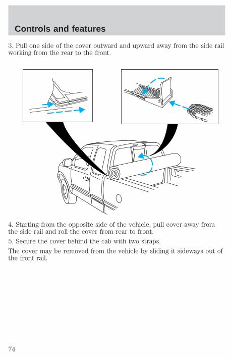
3. Pull one side of the cover outward and upward away from the side railworking from the rear to the front.
4. Starting from the opposite side of the vehicle, pull cover away fromthe side rail and roll the cover from rear to front.
5. Secure the cover behind the cab with two straps.
The cover may be removed from the vehicle by sliding it sideways out ofthe front rail.
Controls and features
74

Flareside only:
• Remove two cross bars from pickup box by pushing towards eitherside to release tension.
• Lower tailgate, depress the levers on each side of the rear rail andremove rear rail from pickup box.
Controls and features
75
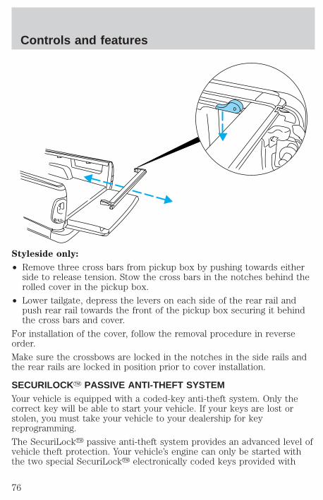
Styleside only:
• Remove three cross bars from pickup box by pushing towards eitherside to release tension. Stow the cross bars in the notches behind therolled cover in the pickup box.
• Lower tailgate, depress the levers on each side of the rear rail andpush rear rail towards the front of the pickup box securing it behindthe cross bars and cover.
For installation of the cover, follow the removal procedure in reverseorder.
Make sure the crossbows are locked in the notches in the side rails andthe rear rails are locked in position prior to cover installation.
SECURILOCKY PASSIVE ANTI-THEFT SYSTEMYour vehicle is equipped with a coded-key anti-theft system. Only thecorrect key will be able to start your vehicle. If your keys are lost orstolen, you must take your vehicle to your dealership for keyreprogramming.
The SecuriLocky passive anti-theft system provides an advanced level ofvehicle theft protection. Your vehicle’s engine can only be started withthe two special SecuriLocky electronically coded keys provided with
Controls and features
76
your vehicle. Each time you start your vehicle, the SecuriLocky key isread by the SecuriLocky passive anti-theft system. If the SecuriLockykey identification code matches the code stored in the SecuriLockypassive anti-theft system, the vehicle’s engine is allowed to start. If theSecuriLocky key identification code does not match the code stored inthe system or if a SecuriLocky key is not detected (vehicle theftsituation), the vehicle’s engine will not operate.
The SecuriLocky passive anti-theft system is not compatible withaftermarket remote start systems. Use of these systems may result invehicle starting problems and a loss of security protection. Large metallicobjects or devices such as the Mobil Speedpassy on the same key ringas your SecuriLocky key may cause vehicle starting problems. Theseobjects and devices cannot damage the SecuriLocky key, but can causea momentary problem if they are too close to the key when starting theengine. If a problem occurs. turn ignition off and restart the engine withall other objects on the key ring held away from the SecuriLockyignition key.
Spare SecuriLocky keys can be purchased from your dealership andprogrammed to your SecuriLocky passive anti-theft system. Refer toProgramming spare SecuriLocky keys for more information.
If one or both of your SecuriLocky keys are lost or stolen and you wantto ensure the lost or stolen key will not operate your vehicle, bring yourvehicle and all available SecuriLocky keys to your dealership forreinitialization.
Theft indicatorThe theft indicator on top of the instrument panel will operate asfollows:
• When the ignition is OFF, the theft indicator will flash briefly every 2seconds to indicate the SecuriLocky system is protecting yourvehicle.
• When the ignition is turned to ON or START, the theft indicator willlight for 3 seconds and then go out. If the theft indicator stays on foran extended period of time or flashes rapidly, have the systemserviced by your dealership or a qualified technician.
Programming spare SecuriLock Y keysSpare SecuriLocky keys can be purchased from your dealership andprogrammed to your SecuriLocky anti-theft system (up to a total of 8
Controls and features
77
keys). Your dealership can program your new SecuriLocky key(s) toyour vehicle or you can do it yourself using the following simpleprocedure. To program a new SecuriLocky key yourself, you will needtwo previously programmed SecuriLocky keys (keys that alreadyoperate your vehicle’s engine). If two previously programmedSecuriLocky keys are not available (one or both of your original keyswere lost or stolen), you must bring your vehicle to your dealership tohave the spare SecuriLocky key(s) programmed.
Procedure to program spare SecuriLock Y keys to your vehicleNew SecuriLocky keys must have the correct mechanical key cut foryour vehicle.
Conventional (non-SecuriLocky) keys cannot be programmed to yourvehicle.
You will need to have two previously programmed SecuriLocky keys andthe new unprogrammed SecuriLocky key readily accessible for timelyimplementation of each step in the procedure. Please read andunderstand the entire procedure before you begin.
1. Insert the first previously programmed SecuriLocky key into theignition and turn the ignition from OFF to RUN (maintain ignition inRUN for at least one second).
2. Turn ignition to OFF and remove the first SecuriLocky key from theignition.
3. Within five seconds of turning the ignition to OFF, insert the secondpreviously programmed SecuriLocky key into the ignition and turn theignition from OFF to RUN (maintain ignition in RUN for at least onesecond but no more than 5 seconds).
4. Turn the ignition to OFF and remove the second SecuriLocky keyfrom the ignition.
5. Within 10 seconds of turning the ignition to OFF, insert theunprogrammed SecuriLocky key (new key/valet key) into the ignitionand turn the ignition from OFF to RUN (maintain ignition in RUN for atleast one second). This step will program your new SecuriLocky key.
6. To program additional SecuriLocky key(s), repeat this procedure fromstep 1.
If the programming procedure was successful, the new SecuriLockykey(s) will start the vehicle’s engine. The theft indicator (located on theinstrument panel) will light for three seconds and then go out.
Controls and features
78
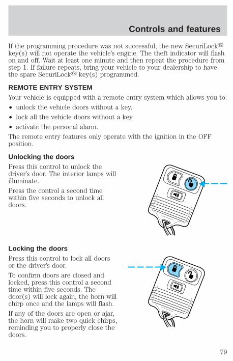
If the programming procedure was not successful, the new SecuriLockykey(s) will not operate the vehicle’s engine. The theft indicator will flashon and off. Wait at least one minute and then repeat the procedure fromstep 1. If failure repeats, bring your vehicle to your dealership to havethe spare SecuriLocky key(s) programmed.
REMOTE ENTRY SYSTEMYour vehicle is equipped with a remote entry system which allows you to:
• unlock the vehicle doors without a key.
• lock all the vehicle doors without a key
• activate the personal alarm.
The remote entry features only operate with the ignition in the OFFposition.
Unlocking the doorsPress this control to unlock thedriver’s door. The interior lamps willilluminate.
Press the control a second timewithin five seconds to unlock alldoors.
Locking the doorsPress this control to lock all doorsor the driver’s door.
To confirm doors are closed andlocked, press this control a secondtime within five seconds. Thedoor(s) will lock again, the horn willchirp once and the lamps will flash.
If any of the doors are open or ajar,the horn will make two quick chirps,reminding you to properly close thedoors.
Controls and features
79
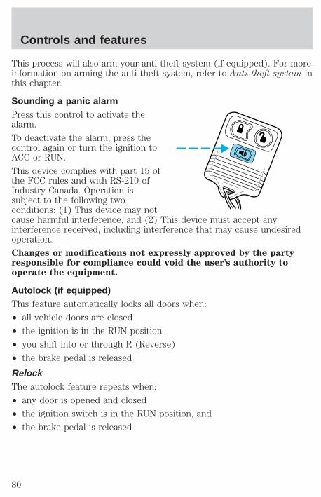
This process will also arm your anti-theft system (if equipped). For moreinformation on arming the anti-theft system, refer to Anti-theft system inthis chapter.
Sounding a panic alarmPress this control to activate thealarm.
To deactivate the alarm, press thecontrol again or turn the ignition toACC or RUN.
This device complies with part 15 ofthe FCC rules and with RS-210 ofIndustry Canada. Operation issubject to the following twoconditions: (1) This device may notcause harmful interference, and (2) This device must accept anyinterference received, including interference that may cause undesiredoperation.
Changes or modifications not expressly approved by the partyresponsible for compliance could void the user’s authority tooperate the equipment.
Autolock (if equipped)This feature automatically locks all doors when:
• all vehicle doors are closed
• the ignition is in the RUN position
• you shift into or through R (Reverse)
• the brake pedal is released
RelockThe autolock feature repeats when:
• any door is opened and closed
• the ignition switch is in the RUN position, and
• the brake pedal is released
Controls and features
80
Deactivating/activating the autolock featureBefore following the procedure, make sure that the ignition is OFF andall vehicle doors and the liftgate window are closed.
You must complete steps 1-7 within 30 seconds or the procedure willhave to be repeated. If the procedure needs to be repeated, you mustwait 30 seconds.
1. Turn the ignition key to RUN.
2. Press the power door unlock control three times.
3. Turn the ignition key from RUN to OFF.
4. Press the power door unlock control three times.
5. Turn the ignition back to RUN. The horn will chirp.
6. Press the unlock control, then press the lock control. The horn willchirp once if autolock was deactivated or twice (one short and one longchirp) if autolock was activated.
7. Turn the ignition to OFF. The horn will chirp once to confirm theprocedure is complete.
Replacing the batteryThe transmitter is powered by one coin type three-volt lithium batteryCR2032 or equivalent. Typical operating range will allow you to be up to10 meters (33 feet) away from your vehicle. A decrease in operatingrange can be caused by:
• weather conditions
• nearby radio towers
• structures around the vehicle
• other vehicles parked next to the vehicle
Controls and features
81

To replace the battery:
1. Twist a thin coin between the twohalves of the transmitter near thekey ring. DO NOT TAKE THEFRONT PART OF THETRANSMITTER APART.
2. Place the positive (+) side of newbattery in the same orientation.Refer to the diagram inside thetransmitter unit.
3. Snap the two halves backtogether.
Replacement of the battery will not cause the remote transmitter tobecome deprogrammed from your vehicle. The remote transmitter shouldoperate normally after battery replacement.
Replacing lost transmittersIf a remote transmitter has been lostor you would like to purchaseadditional transmitters for yourvehicle (up to four may beprogrammed), take all your vehicle’stransmitters to your dealer forreprogramming. It will be necessaryfor your dealer to reprogram all theremote transmitters to your vehiclewhile performing this service.
Reprogramming transmittersYour dealer will be able to reprogram remote transmitter(s) to yourvehicle. Installation of a new battery to your remote transmitter does notcause the remote transmitter to become deprogrammed.
Controls and features
82
Illuminated entryThe illuminated entry system will turn on the interior lights when theremote transmitter unlock control is pressed.
The illuminated entry system will turn off the interior lights if theignition switch is turned to the RUN position, or if the remotetransmitter lock control is pressed, or after 25 seconds of illumination.
The inside lights will not turn off if:
• they have been turned on with the dimmer control or
• any door is open.
The battery save feature will turn off the interior lights 45 minutes afterthe last door is closed, even if the dimmer control is on.
Controls and features
83
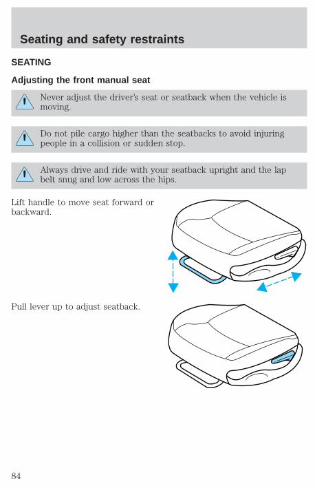
SEATING
Adjusting the front manual seat
Never adjust the driver’s seat or seatback when the vehicle ismoving.
Do not pile cargo higher than the seatbacks to avoid injuringpeople in a collision or sudden stop.
Always drive and ride with your seatback upright and the lapbelt snug and low across the hips.
Lift handle to move seat forward orbackward.
Pull lever up to adjust seatback.
Seating and safety restraints
84
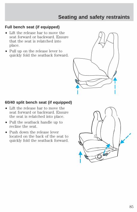
Full bench seat (if equipped)• Lift the release bar to move the
seat forward or backward. Ensurethat the seat is relatched intoplace.
• Pull up on the release lever toquickly fold the seatback forward.
60/40 split bench seat (if equipped)• Lift the release bar to move the
seat forward or backward. Ensurethe seat is relatched into place.
• Pull the seatback handle up torecline the seat.
• Push down the release leverlocated on the back of the seat toquickly fold the seatback forward.
Seating and safety restraints
85
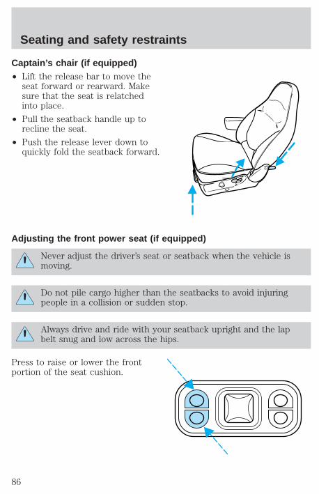
Captain’s chair (if equipped)• Lift the release bar to move the
seat forward or rearward. Makesure that the seat is relatchedinto place.
• Pull the seatback handle up torecline the seat.
• Push the release lever down toquickly fold the seatback forward.
Adjusting the front power seat (if equipped)
Never adjust the driver’s seat or seatback when the vehicle ismoving.
Do not pile cargo higher than the seatbacks to avoid injuringpeople in a collision or sudden stop.
Always drive and ride with your seatback upright and the lapbelt snug and low across the hips.
Press to raise or lower the frontportion of the seat cushion.
Seating and safety restraints
86
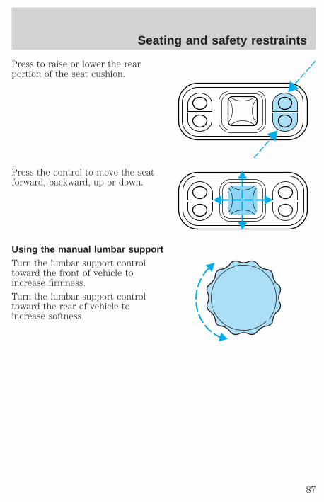
Press to raise or lower the rearportion of the seat cushion.
Press the control to move the seatforward, backward, up or down.
Using the manual lumbar supportTurn the lumbar support controltoward the front of vehicle toincrease firmness.
Turn the lumbar support controltoward the rear of vehicle toincrease softness.
Seating and safety restraints
87
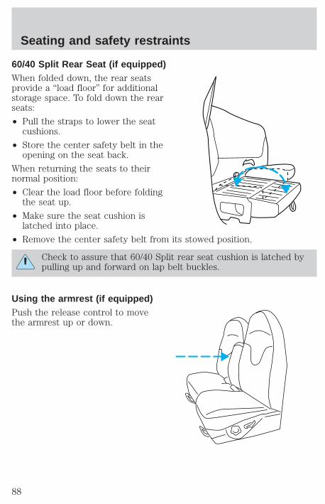
60/40 Split Rear Seat (if equipped)When folded down, the rear seatsprovide a “load floor” for additionalstorage space. To fold down the rearseats:
• Pull the straps to lower the seatcushions.
• Store the center safety belt in theopening on the seat back.
When returning the seats to theirnormal position:
• Clear the load floor before foldingthe seat up.
• Make sure the seat cushion islatched into place.
• Remove the center safety belt from its stowed position.
Check to assure that 60/40 Split rear seat cushion is latched bypulling up and forward on lap belt buckles.
Using the armrest (if equipped)Push the release control to movethe armrest up or down.
Seating and safety restraints
88
SAFETY RESTRAINTS
Safety restraints precautions
Always drive and ride with your seatback upright and the lapbelt snug and low across the hips.
To prevent the risk of injury, make sure children sit where theycan be properly restrained.
Never let a passenger hold a child on his or her lap while thevehicle is moving. The passenger cannot protect the child from
injury in a collision.
All occupants of the vehicle, including the driver, should alwaysproperly wear their safety belts, even when an air bag SRS is
provided.
It is extremely dangerous to ride in a cargo area, inside oroutside of a vehicle. In a collision, people riding in these areas
are more likely to be seriously injured or killed. Do not allow people toride in any area of your vehicle that is not equipped with seats andsafety belts. Be sure everyone in your vehicle is in a seat and using asafety belt properly.
Each seating position in your vehicle has a specific safety beltassembly which is made up of one buckle and one tongue that
are designed to be used as a pair. 1) Use the shoulder belt on theoutside shoulder only. Never wear the shoulder belt under the arm. 2)Never swing the safety belt around your neck over the inside shoulder.3) Never use a single belt for more than one person.
Seating and safety restraints
89
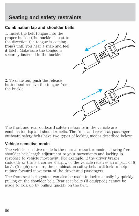
Combination lap and shoulder belts1. Insert the belt tongue into theproper buckle (the buckle closest tothe direction the tongue is comingfrom) until you hear a snap and feelit latch. Make sure the tongue issecurely fastened in the buckle.
2. To unfasten, push the releasebutton and remove the tongue fromthe buckle.
The front and rear outboard safety restraints in the vehicle arecombination lap and shoulder belts. The front and rear seat passengeroutboard safety belts have two types of locking modes described below:
Vehicle sensitive modeThe vehicle sensitive mode is the normal retractor mode, allowing freeshoulder belt length adjustment to your movements and locking inresponse to vehicle movement. For example, if the driver brakessuddenly or turns a corner sharply, or the vehicle receives an impact of 8km/h (5 mph) or more, the combination safety belts will lock to helpreduce forward movement of the driver and passengers.
The front seat belt system can also be made to lock manually by quicklypulling on the shoulder belt. Rear seat belts (if equipped) cannot bemade to lock up by pulling quickly on the belt.
Seating and safety restraints
90
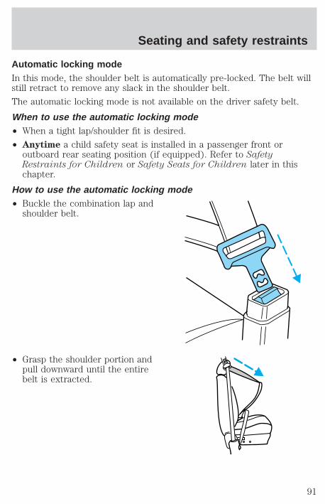
Automatic locking modeIn this mode, the shoulder belt is automatically pre-locked. The belt willstill retract to remove any slack in the shoulder belt.
The automatic locking mode is not available on the driver safety belt.
When to use the automatic locking mode• When a tight lap/shoulder fit is desired.
• Anytime a child safety seat is installed in a passenger front oroutboard rear seating position (if equipped). Refer to SafetyRestraints for Children or Safety Seats for Children later in thischapter.
How to use the automatic locking mode• Buckle the combination lap and
shoulder belt.
• Grasp the shoulder portion andpull downward until the entirebelt is extracted.
Seating and safety restraints
91
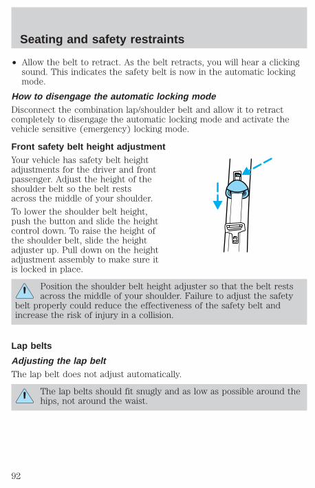
• Allow the belt to retract. As the belt retracts, you will hear a clickingsound. This indicates the safety belt is now in the automatic lockingmode.
How to disengage the automatic locking modeDisconnect the combination lap/shoulder belt and allow it to retractcompletely to disengage the automatic locking mode and activate thevehicle sensitive (emergency) locking mode.
Front safety belt height adjustmentYour vehicle has safety belt heightadjustments for the driver and frontpassenger. Adjust the height of theshoulder belt so the belt restsacross the middle of your shoulder.
To lower the shoulder belt height,push the button and slide the heightcontrol down. To raise the height ofthe shoulder belt, slide the heightadjuster up. Pull down on the heightadjustment assembly to make sure itis locked in place.
Position the shoulder belt height adjuster so that the belt restsacross the middle of your shoulder. Failure to adjust the safety
belt properly could reduce the effectiveness of the safety belt andincrease the risk of injury in a collision.
Lap belts
Adjusting the lap beltThe lap belt does not adjust automatically.
The lap belts should fit snugly and as low as possible around thehips, not around the waist.
Seating and safety restraints
92
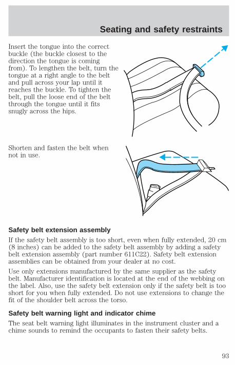
Insert the tongue into the correctbuckle (the buckle closest to thedirection the tongue is comingfrom). To lengthen the belt, turn thetongue at a right angle to the beltand pull across your lap until itreaches the buckle. To tighten thebelt, pull the loose end of the beltthrough the tongue until it fitssnugly across the hips.
Shorten and fasten the belt whennot in use.
Safety belt extension assemblyIf the safety belt assembly is too short, even when fully extended, 20 cm(8 inches) can be added to the safety belt assembly by adding a safetybelt extension assembly (part number 611C22). Safety belt extensionassemblies can be obtained from your dealer at no cost.
Use only extensions manufactured by the same supplier as the safetybelt. Manufacturer identification is located at the end of the webbing onthe label. Also, use the safety belt extension only if the safety belt is tooshort for you when fully extended. Do not use extensions to change thefit of the shoulder belt across the torso.
Safety belt warning light and indicator chimeThe seat belt warning light illuminates in the instrument cluster and achime sounds to remind the occupants to fasten their safety belts.
Seating and safety restraints
93

Conditions of operation
If... Then...
The driver’s safety belt is notbuckled before the ignition switchis turned to the ON position...
The safety belt warning lightilluminates for one to two minutesand the warning chime sounds forfour to eight seconds.
The driver’s safety belt is buckledwhile the indicator light isilluminated and the warning chimeis sounding...
The safety belt warning light andwarning chime turn off.
The driver’s safety belt is buckledbefore the ignition switch is turnedto the ON position...
The safety belt warning light andindicator chime remain off.
Safety belt maintenanceInspect the safety belt systems periodically to make sure they workproperly and are not damaged. Inspect the safety belts to make surethere are no nicks, wears or cuts, replacing if necessary. All safety beltassemblies, including retractors, buckles, front seat belt buckleassemblies (slide bar)(if equipped), shoulder belt height adjusters (ifequipped), child safety seat tether bracket assemblies (if equipped), andattaching hardware, should be inspected after a collision. Fordrecommends that all safety belt assemblies used in vehicles involved in acollision be replaced. However, if the collision was minor and a qualifiedtechnician finds that the belts do not show damage and continue tooperate properly, they do not need to be replaced. Safety belt assembliesnot in use during a collision should also be inspected and replaced ifeither damage or improper operation is noted.
Failure to inspect and if necessary replace the safety beltassembly under the above conditions could result in severe
personal injuries in the event of a collision.
Refer to Cleaning and maintaining the safety belts in theMaintenance and care section.
Seating and safety restraints
94
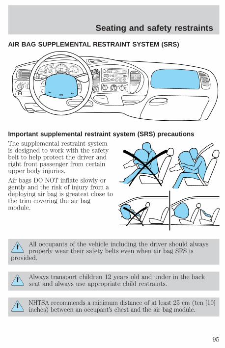
AIR BAG SUPPLEMENTAL RESTRAINT SYSTEM (SRS)
Important supplemental restraint system (SRS) precautionsThe supplemental restraint systemis designed to work with the safetybelt to help protect the driver andright front passenger from certainupper body injuries.
Air bags DO NOT inflate slowly orgently and the risk of injury from adeploying air bag is greatest close tothe trim covering the air bagmodule.
All occupants of the vehicle including the driver should alwaysproperly wear their safety belts even when air bag SRS is
provided.
Always transport children 12 years old and under in the backseat and always use appropriate child restraints.
NHTSA recommends a minimum distance of at least 25 cm (ten [10]inches) between an occupant’s chest and the air bag module.
FOR
SCAN EJ
REW FF SIDE 1-2 COMP SHUFFLE
TAPE CDDISCS
BASS TREB BAL FADE AUTOSET
VOL - PUSH ON
SEEKTUNE
AMFM
1 2 3 4 5 6
fw DOLBY B NR
FM1 ST
DOORAJAR
BRAKE
F
E
H
H
18
8
20
10
30
4050 60
70
80
90
100
20
40
60
80 100
120
140
160
MPH km/h0 0
0 0 0 0 0 0
0
1
2
P R N 2 1RPMx1000
CHECK
ENGINE
THEFT
34
5
6
CHECK
SUSP
LOWFUEL
ABS
P PULL
FOGPANEL
DIM
4HA4WD
4L
OVERDRIVE
SRS
ON
OFF
RES
SETACCEL
COAST
FLOOR
PANEL
LO
HI
COOL WARM
DEF
FLR&DEF
PANEL &FLOOR
OFF
Seating and safety restraints
95
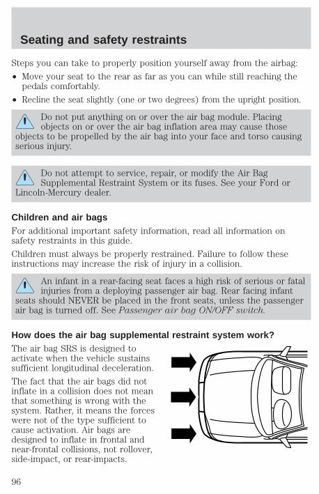
Steps you can take to properly position yourself away from the airbag:
• Move your seat to the rear as far as you can while still reaching thepedals comfortably.
• Recline the seat slightly (one or two degrees) from the upright position.
Do not put anything on or over the air bag module. Placingobjects on or over the air bag inflation area may cause those
objects to be propelled by the air bag into your face and torso causingserious injury.
Do not attempt to service, repair, or modify the Air BagSupplemental Restraint System or its fuses. See your Ford or
Lincoln-Mercury dealer.
Children and air bagsFor additional important safety information, read all information onsafety restraints in this guide.
Children must always be properly restrained. Failure to follow theseinstructions may increase the risk of injury in a collision.
An infant in a rear-facing seat faces a high risk of serious or fatalinjuries from a deploying passenger air bag. Rear facing infant
seats should NEVER be placed in the front seats, unless the passengerair bag is turned off. See Passenger air bag ON/OFF switch.
How does the air bag supplemental restraint system work?The air bag SRS is designed toactivate when the vehicle sustainssufficient longitudinal deceleration.
The fact that the air bags did notinflate in a collision does not meanthat something is wrong with thesystem. Rather, it means the forceswere not of the type sufficient tocause activation. Air bags aredesigned to inflate in frontal andnear-frontal collisions, not rollover,side-impact, or rear-impacts.
Seating and safety restraints
96
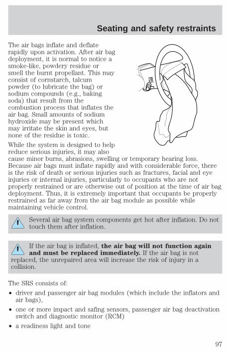
The air bags inflate and deflaterapidly upon activation. After air bagdeployment, it is normal to notice asmoke-like, powdery residue orsmell the burnt propellant. This mayconsist of cornstarch, talcumpowder (to lubricate the bag) orsodium compounds (e.g., bakingsoda) that result from thecombustion process that inflates theair bag. Small amounts of sodiumhydroxide may be present whichmay irritate the skin and eyes, butnone of the residue is toxic.
While the system is designed to helpreduce serious injuries, it may alsocause minor burns, abrasions, swelling or temporary hearing loss.Because air bags must inflate rapidly and with considerable force, thereis the risk of death or serious injuries such as fractures, facial and eyeinjuries or internal injuries, particularly to occupants who are notproperly restrained or are otherwise out of position at the time of air bagdeployment. Thus, it is extremely important that occupants be properlyrestrained as far away from the air bag module as possible whilemaintaining vehicle control.
Several air bag system components get hot after inflation. Do nottouch them after inflation.
If the air bag is inflated, the air bag will not function againand must be replaced immediately. If the air bag is not
replaced, the unrepaired area will increase the risk of injury in acollision.
The SRS consists of:
• driver and passenger air bag modules (which include the inflators andair bags),
• one or more impact and safing sensors, passenger air bag deactivationswitch and diagnostic monitor (RCM)
• a readiness light and tone
Seating and safety restraints
97
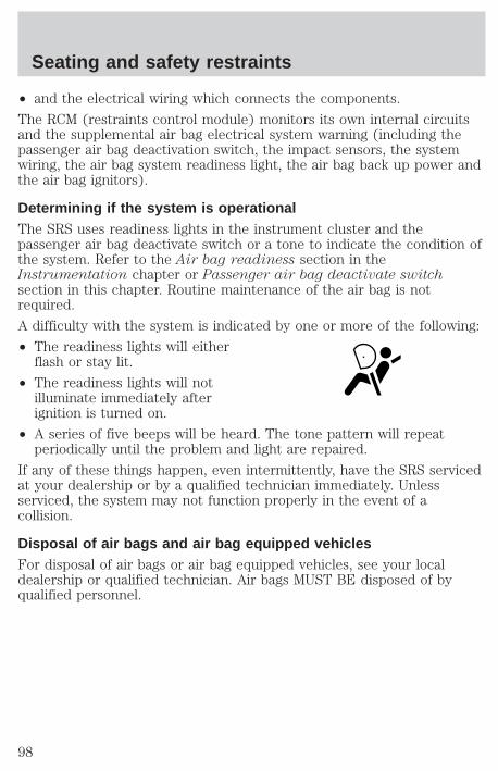
• and the electrical wiring which connects the components.
The RCM (restraints control module) monitors its own internal circuitsand the supplemental air bag electrical system warning (including thepassenger air bag deactivation switch, the impact sensors, the systemwiring, the air bag system readiness light, the air bag back up power andthe air bag ignitors).
Determining if the system is operationalThe SRS uses readiness lights in the instrument cluster and thepassenger air bag deactivate switch or a tone to indicate the condition ofthe system. Refer to the Air bag readiness section in theInstrumentation chapter or Passenger air bag deactivate switchsection in this chapter. Routine maintenance of the air bag is notrequired.
A difficulty with the system is indicated by one or more of the following:
• The readiness lights will eitherflash or stay lit.
• The readiness lights will notilluminate immediately afterignition is turned on.
• A series of five beeps will be heard. The tone pattern will repeatperiodically until the problem and light are repaired.
If any of these things happen, even intermittently, have the SRS servicedat your dealership or by a qualified technician immediately. Unlessserviced, the system may not function properly in the event of acollision.
Disposal of air bags and air bag equipped vehiclesFor disposal of air bags or air bag equipped vehicles, see your localdealership or qualified technician. Air bags MUST BE disposed of byqualified personnel.
Seating and safety restraints
98
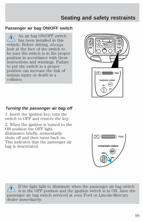
Passenger air bag ON/OFF switch
An air bag ON/OFF switchhas been installed in this
vehicle. Before driving, alwayslook at the face of the switch tobe sure the switch is in the properposition in accordance with theseinstructions and warnings. Failureto put the switch in a properposition can increase the risk ofserious injury or death in acollision.
Turning the passenger air bag off1. Insert the ignition key, turn theswitch to OFF and remove the key.
2. When the ignition is turned to theON position the OFF lightilluminates briefly, momentarilyshuts off and then turns back on.This indicates that the passenger airbag is deactivated.
If the light fails to illuminate when the passenger air bag switchis in the OFF position and the ignition switch is in ON, have the
passenger air bag switch serviced at your Ford or Lincoln-Mercurydealer immediately.
PASSENGER AIRBAG
ON
OFF
OFF
PASSENGER AIRBAG
ON
OFF
OFF
Seating and safety restraints
99
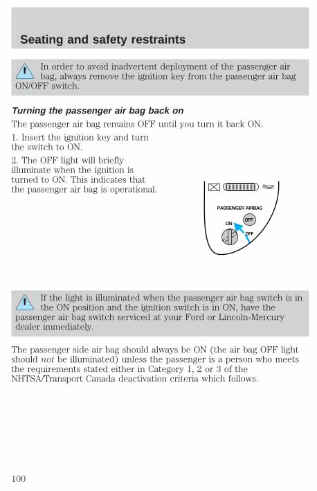
In order to avoid inadvertent deployment of the passenger airbag, always remove the ignition key from the passenger air bag
ON/OFF switch.
Turning the passenger air bag back onThe passenger air bag remains OFF until you turn it back ON.
1. Insert the ignition key and turnthe switch to ON.
2. The OFF light will brieflyilluminate when the ignition isturned to ON. This indicates thatthe passenger air bag is operational.
If the light is illuminated when the passenger air bag switch is inthe ON position and the ignition switch is in ON, have the
passenger air bag switch serviced at your Ford or Lincoln-Mercurydealer immediately.
The passenger side air bag should always be ON (the air bag OFF lightshould not be illuminated) unless the passenger is a person who meetsthe requirements stated either in Category 1, 2 or 3 of theNHTSA/Transport Canada deactivation criteria which follows.
PASSENGER AIRBAG
ON
OFF
OFF
Seating and safety restraints
100

The safety belts for the driver and right front passenger seatingpositions have been specifically designed to function together with
the air bags in certain types of crashes. When you turn OFF your air bag,you not only lose the protection of the air bag, you also may reduce theeffectiveness of your safety belt system, which was designed to work withthe air bag. If you are not a person who meets the requirements stated inthe NHTSA/Transport Canada deactivation criteria turning OFF the air bagcan increase the risk of serious injury or death in a collision.
Always transport children who are 12 and younger in the rearseat. Always use safety belts and child restraints properly. If a
child in a rear facing infant seat must be transported in front, thepassenger air bag must be turned OFF. This is because the back of theinfant seat is too close to the inflating air bag and the risk of a fatalinjury to the infant when the air bag inflates is substantial.
The vast majority of drivers and passengers are much safer with an airbag than without. To do their job and reduce the risk of life threateninginjuries, air bags must open with great force, and this force can pose apotentially deadly risk in some situations, particularly when a front seatoccupant is not properly buckled up. The most effective way to reducethe risk of unnecessary air bag injuries without reducing the overallsafety of the vehicle is to make sure all occupants are properlyrestrained in the vehicle, especially in the front seat. This provides theprotection of safety belts and permits the air bags to provide theadditional protection they were designed to provide. If you choose todeactivate your air bag, you are losing the very significant risk reducingbenefits of the air bag and you are also reducing the effectiveness of thesafety belts, because safety belts in modern vehicles are designed towork as a safety system with the air bags.
Read all air bag Warning labels in the vehicle as well as the otherimportant air bag instructions and Warnings in this Owner’s Guide.
NHTSA deactivation criteria (excluding Canada)1. Infant. An infant (less than 1 year old) must ride in the front seatbecause:
• the vehicle has no rear seat;
• the vehicle has a rear seat too small to accommodate a rear-facinginfant seat; or
Seating and safety restraints
101
• the infant has a medical condition which, according to the infant’sphysician, makes it necessary for the infant to ride in the front so thatthe driver can constantly monitor the child’s condition.
2. Child age 1 to 12. A child age 1 to 12 must ride in the front seatbecause:
• the vehicle has no rear seat;
• although children ages 1 to 12 ride in the rear seat(s) wheneverpossible, children ages 1 to 12 sometimes must ride in the frontbecause no space is available in the rear seat(s) of the vehicle; or
• the child has a medical condition which, according to the child’sphysician, makes it necessary for the child to ride in the front seat sothat the driver can constantly monitor the child’s condition.
3. Medical condition. A passenger has a medical condition which,according to his or her physician:
• causes the passenger air bag to pose a special risk for the passenger;and
• makes the potential harm from the passenger air bag in a crashgreater than the potential harm from turning OFF the air bag andallowing the passenger, even if belted, to hit the dashboard orwindshield in a crash.
Transport Canada deactivation criteria (Canada Only)1. Infant: An infant (less than 1 year old) must ride in the front seatbecause:
• my vehicle has no rear seat;
• the rear seat in my vehicle cannot accommodate a rear-facing infantseat; or
• the infant has a medical condition which, according to the infant’sphysician, makes it necessary for the infant to ride in the front seat sothat the driver can monitor the infant’s condition.
2. Child age 12 or under: A child age 12 or under must ride in thefront seat because:
• my vehicle has no rear seat;
• although children age 12 and under ride in the rear seat wheneverpossible, children age 12 and under have no option but to sometimesride in the front seat because rear seat space is insufficient; or
Seating and safety restraints
102
• the child has a medical condition that, according to the child’sphysician, makes it necessary for the child to ride in the front seat sothat the driver can monitor the child’s condition.
3. Medical condition: A passenger has a medical condition that,according to his or her physician:
• poses a special risk for the passenger if the air bag deploys; and
• makes the potential harm from the passenger air bag deploymentgreater than the potential harm from turning OFF the air bag andexperiencing a crash without the protection offered by the air bag
SAFETY RESTRAINTS FOR CHILDRENSee the following sections for directions on how to properly use safetyrestraints for children. Also see Air Bag Supplemental Restraint System(SRS) in this chapter for special instructions about using air bags.
Important child restraint precautionsYou are required by law to use safety restraints for children in the U.S.and Canada. If small children ride in your vehicle (generally children whoare four years old or younger and who weigh 18 kg [40 lbs] or less), youmust put them in safety seats made especially for children. Check yourlocal and state or provincial laws for specific requirements regarding thesafety of children in your vehicle.
Never let a passenger hold a child on his or her lap while thevehicle is moving. The passenger cannot protect the child from
injury in a collision.
Always follow the instructions and warnings that come with any infant orchild restraint you might use.
When possible, place children in the rear seat of your vehicle. Accidentstatistics suggest that children are safer when properly restrained in therear seating positions than in the front seating position.
Children and safety beltsIf the child is the proper size, restrain the child in a safety seat.
Children who are too large for child safety seats (as specified by yourchild safety seat manufacturer) should always wear safety belts.
Seating and safety restraints
103
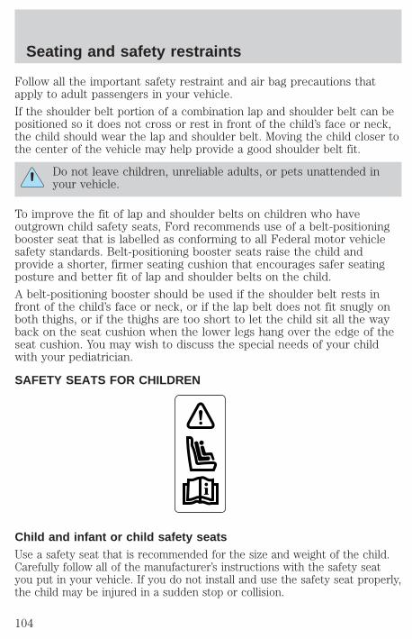
Follow all the important safety restraint and air bag precautions thatapply to adult passengers in your vehicle.
If the shoulder belt portion of a combination lap and shoulder belt can bepositioned so it does not cross or rest in front of the child’s face or neck,the child should wear the lap and shoulder belt. Moving the child closer tothe center of the vehicle may help provide a good shoulder belt fit.
Do not leave children, unreliable adults, or pets unattended inyour vehicle.
To improve the fit of lap and shoulder belts on children who haveoutgrown child safety seats, Ford recommends use of a belt-positioningbooster seat that is labelled as conforming to all Federal motor vehiclesafety standards. Belt-positioning booster seats raise the child andprovide a shorter, firmer seating cushion that encourages safer seatingposture and better fit of lap and shoulder belts on the child.
A belt-positioning booster should be used if the shoulder belt rests infront of the child’s face or neck, or if the lap belt does not fit snugly onboth thighs, or if the thighs are too short to let the child sit all the wayback on the seat cushion when the lower legs hang over the edge of theseat cushion. You may wish to discuss the special needs of your childwith your pediatrician.
SAFETY SEATS FOR CHILDREN
Child and infant or child safety seatsUse a safety seat that is recommended for the size and weight of the child.Carefully follow all of the manufacturer’s instructions with the safety seatyou put in your vehicle. If you do not install and use the safety seat properly,the child may be injured in a sudden stop or collision.
Seating and safety restraints
104
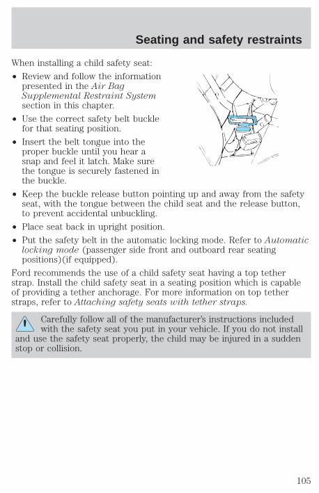
When installing a child safety seat:
• Review and follow the informationpresented in the Air BagSupplemental Restraint Systemsection in this chapter.
• Use the correct safety belt bucklefor that seating position.
• Insert the belt tongue into theproper buckle until you hear asnap and feel it latch. Make surethe tongue is securely fastened inthe buckle.
• Keep the buckle release button pointing up and away from the safetyseat, with the tongue between the child seat and the release button,to prevent accidental unbuckling.
• Place seat back in upright position.
• Put the safety belt in the automatic locking mode. Refer to Automaticlocking mode (passenger side front and outboard rear seatingpositions)(if equipped).
Ford recommends the use of a child safety seat having a top tetherstrap. Install the child safety seat in a seating position which is capableof providing a tether anchorage. For more information on top tetherstraps, refer to Attaching safety seats with tether straps.
Carefully follow all of the manufacturer’s instructions includedwith the safety seat you put in your vehicle. If you do not install
and use the safety seat properly, the child may be injured in a suddenstop or collision.
Seating and safety restraints
105
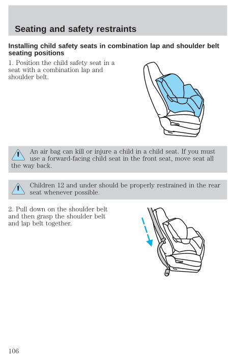
Installing child safety seats in combination lap and shoulder beltseating positions1. Position the child safety seat in aseat with a combination lap andshoulder belt.
An air bag can kill or injure a child in a child seat. If you mustuse a forward-facing child seat in the front seat, move seat all
the way back.
Children 12 and under should be properly restrained in the rearseat whenever possible.
2. Pull down on the shoulder beltand then grasp the shoulder beltand lap belt together.
Seating and safety restraints
106
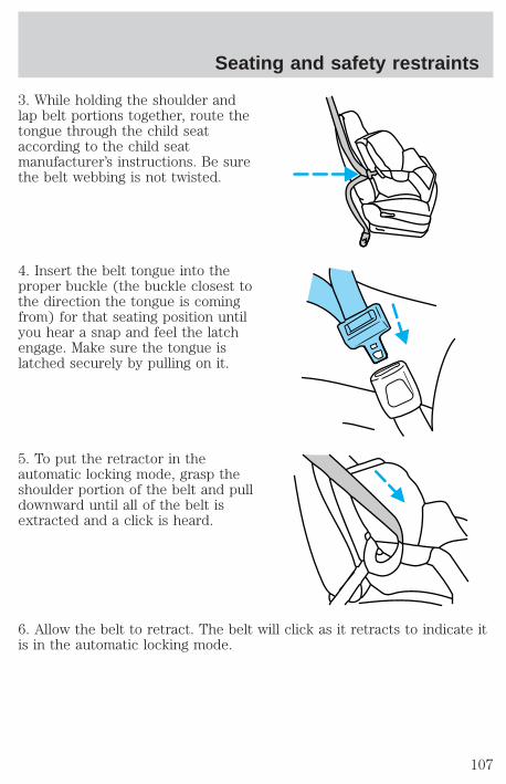
3. While holding the shoulder andlap belt portions together, route thetongue through the child seataccording to the child seatmanufacturer’s instructions. Be surethe belt webbing is not twisted.
4. Insert the belt tongue into theproper buckle (the buckle closest tothe direction the tongue is comingfrom) for that seating position untilyou hear a snap and feel the latchengage. Make sure the tongue islatched securely by pulling on it.
5. To put the retractor in theautomatic locking mode, grasp theshoulder portion of the belt and pulldownward until all of the belt isextracted and a click is heard.
6. Allow the belt to retract. The belt will click as it retracts to indicate itis in the automatic locking mode.
Seating and safety restraints
107
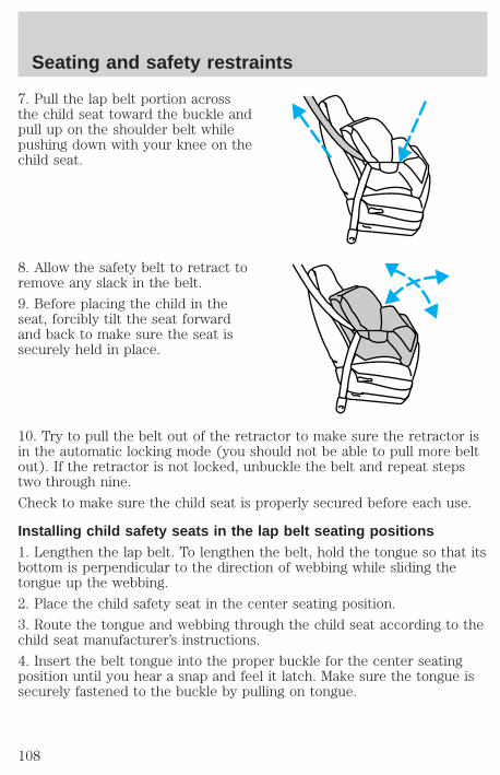
7. Pull the lap belt portion acrossthe child seat toward the buckle andpull up on the shoulder belt whilepushing down with your knee on thechild seat.
8. Allow the safety belt to retract toremove any slack in the belt.
9. Before placing the child in theseat, forcibly tilt the seat forwardand back to make sure the seat issecurely held in place.
10. Try to pull the belt out of the retractor to make sure the retractor isin the automatic locking mode (you should not be able to pull more beltout). If the retractor is not locked, unbuckle the belt and repeat stepstwo through nine.
Check to make sure the child seat is properly secured before each use.
Installing child safety seats in the lap belt seating positions1. Lengthen the lap belt. To lengthen the belt, hold the tongue so that itsbottom is perpendicular to the direction of webbing while sliding thetongue up the webbing.
2. Place the child safety seat in the center seating position.
3. Route the tongue and webbing through the child seat according to thechild seat manufacturer’s instructions.
4. Insert the belt tongue into the proper buckle for the center seatingposition until you hear a snap and feel it latch. Make sure the tongue issecurely fastened to the buckle by pulling on tongue.
Seating and safety restraints
108
5. Push down on the child seat while pulling on the loose end of the lapbelt webbing to tighten the belt.
6. Before placing the child into the child seat, forcibly tilt the child seatfrom side to side and in forward direction to make sure that the seat isheld securely in place. If the child seat moves excessively, repeat steps 5through 6, or properly install the child seat in a different position.
Attaching safety seats with tether strapsSome manufacturers make safety seats that include a tether strap thatgoes over the back of the vehicle seat and attaches to an anchoringpoint. Other manufacturers offer the tether strap as an accessory.Contact the manufacturer of your child safety seat for information aboutordering a tether strap.
Tether anchorage hardwareA tethered seat can be installed in the front passenger seat. Put thetether strap over the seatback and attach it to an anchor bracket.
An anchor bracket can be installed on the rear edge of the frontpassenger seat cushion.
The provision (attaching hole) is provided in the rear edge of the frontpassenger seat cushion frame. The anchor bracket must be installedusing the instructions provided with the kit.
Tether anchorage hardware kits (part number 613D74) includinginstructions, may be obtained at no charge from any Ford orLincoln-Mercury dealer.
If you have a SuperCab, attach the bracket to the inside of the backpanel of your vehicle. Carefully follow the instructions provided with thekit.
If you have a SuperCab, Ford recommends you attach tether safety seatsin the rear seating position (if possible) with the tether strap attached tothe tether anchorage bracket as shown in the instructions provided withthe tether anchor kit.
Tighten the anchor according to specifications. Otherwise, thesafety seat may not be properly secured and the child may be
injured in a sudden stop or collision.
Seating and safety restraints
109
PREPARING TO START YOUR VEHICLEEngine starting is controlled by the ignition system. This system meetsall Canadian Interference-Causing Equipment standard requirementsregulating the impulse electrical field strength of radio noise.
When starting a fuel-injected engine, avoid pressing the acceleratorbefore or during starting. Only use the accelerator when you havedifficulty starting the engine. For more information on starting thevehicle, refer to Starting the engine in this chapter.
Extended idling at high engine speeds can produce very hightemperatures in the engine and exhaust system, creating the risk
of fire or other damage.
Do not park, idle, or drive your vehicle in dry grass or other dryground cover. The emission system heats up the engine
compartment and exhaust system, which can start a fire.
Do not start your vehicle in a closed garage or in other enclosedareas. Exhaust fumes can be toxic. Always open the garage door
before you start the engine. See Guarding against exhaust fumes inthis chapter for more instructions.
If you smell exhaust fumes inside your vehicle, have your dealerinspect your vehicle immediately. Do not drive if you smell
exhaust fumes.
Important safety precautionsA computer system controls the engine’s idle revolutions per minute(RPM). When the engine starts, the idle RPM runs faster to warm theengine. If the engine idle speed does not slow down automatically, havethe vehicle checked. Do not allow the vehicle to idle for more than tenminutes at high engine RPM.
Before starting the vehicle:
1. Make sure all vehicle occupants have buckled their safety belts. Formore information on safety belts and their proper usage, refer to theSeating and safety restraints chapter.
Starting
110

2. Make sure the headlamps and vehicle accessories are off.
If starting a vehicle with an automatic transmission:
• Make sure the parking brake isset.
• Make sure the gearshift is in P (Park).
If starting a vehicle with a manual transmission:
• Make sure the parking brake is set.
• Push the clutch pedal to thefloor.
BRAKE
HOOD
Starting
111
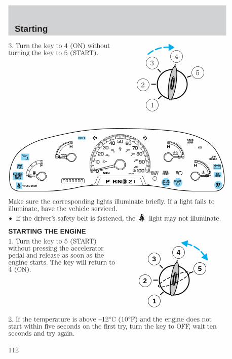
3. Turn the key to 4 (ON) withoutturning the key to 5 (START).
Make sure the corresponding lights illuminate briefly. If a light fails toilluminate, have the vehicle serviced.
• If the driver’s safety belt is fastened, the light may not illuminate.
STARTING THE ENGINE1. Turn the key to 5 (START)without pressing the acceleratorpedal and release as soon as theengine starts. The key will return to4 (ON).
2. If the temperature is above –12°C (10°F) and the engine does notstart within five seconds on the first try, turn the key to OFF, wait tenseconds and try again.
1
2
34
5
0
E
L L
HH
F
C
H
DP RN D 2
FUEL RESET
DOORAJAR
SELECTRESET
4X4
LOWRANGE
CKSUSP
THEFT
FUEL DOOR
20
40
60 80 00
20
40
60
BRAKE
MPH km/hSERVICEENGINESOON
LOW FUEL
3
2
1
5
4
Starting
112
3. If the temperature is below -12°C (10°F) and the engine does notstart in fifteen seconds on the first try, turn the key OFF and wait tenseconds and try again. If the engine does not start in two attempts,depress the accelerator and start the engine while holding theaccelerator down to the floor. Release the accelerator when the enginestarts.
4. After idling for a few seconds, apply the brake and release the parkingbrake.
Using the engine block heater (if equipped)An engine block heater warms the engine coolant, which improvesstarting, warms up the engine faster and allows the heater-defrostersystem to respond quickly. Use of an engine block heater is stronglyrecommended if you live in a region where temperatures reach -23°C(-10°F) or below.
For best results, plug the heater in at least three hours before startingthe vehicle. Using the heater for longer than three hours will not harmthe engine, so the heater can be plugged in the night before starting thevehicle.
To prevent electrical shock, do not use your heater withungrounded electrical systems or two-pronged (cheater)
adapters.
Guarding against exhaust fumesAlthough odorless and colorless, carbon monoxide is present in exhaustfumes. Take precautions to avoid its dangerous effects.
If you ever smell exhaust fumes of any kind inside your vehicle,have your dealer inspect and fix your vehicle immediately. Do
not drive if you smell exhaust fumes. These fumes are harmful andcould kill you.
Have the exhaust and body ventilation systems checked whenever:
• the vehicle is raised for service.
• the sound of the exhaust system changes.
• the vehicle has been damaged in a collision.
Starting
113

Engine exhaust, some of its constituents, and certain vehiclecomponents contain or emit chemicals known to the State of
California to cause cancer, and birth defects or other reproductiveharm.
Important ventilating informationIf the engine is idling while the vehicle is stopped in an open area forlong periods of time, open the windows at least 2.5 cm (one inch).
Adjust the heating or air conditioning (if equipped) to bring in fresh air.
Improve vehicle ventilation bykeeping all air inlet vents clear ofsnow, leaves and other debris.
Starting
114
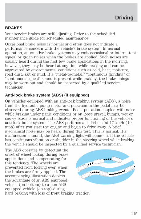
BRAKESYour service brakes are self-adjusting. Refer to the scheduledmaintenance guide for scheduled maintenance.
Occasional brake noise is normal and often does not indicate aperformance concern with the vehicle’s brake system. In normaloperation, automotive brake systems may emit occasional or intermittentsqueal or groan noises when the brakes are applied. Such noises areusually heard during the first few brake applications in the morning;however, they may be heard at any time while braking and can beaggravated by environmental conditions such as cold, heat, moisture,road dust, salt or mud. If a “metal-to-metal,” “continuous grinding” or“continuous squeal” sound is present while braking, the brake liningsmay be worn-out and should be inspected by a qualified servicetechnician.
Anti-lock brake system (ABS) (if equipped)On vehicles equipped with an anti-lock braking system (ABS), a noisefrom the hydraulic pump motor and pulsation in the pedal may beobserved during ABS braking events. Pedal pulsation coupled with noisewhile braking under panic conditions or on loose gravel, bumps, wet orsnowy roads is normal and indicates proper functioning of the vehicle’santi-lock brake system. The ABS performs a self-check at 17 km/h (10mph) after you start the engine and begin to drive away. A briefmechanical noise may be heard during this test. This is normal. If amalfunction is found, the ABS warning light will come on. If the vehiclehas continuous vibration or shudder in the steering wheel while braking,the vehicle should be inspected by a qualified service technician.
The ABS operates by detecting theonset of wheel lockup during brakeapplications and compensating forthis tendency. The wheels areprevented from locking even whenthe brakes are firmly applied. Theaccompanying illustration depictsthe advantage of an ABS equippedvehicle (on bottom) to a non-ABSequipped vehicle (on top) duringhard braking with loss of front braking traction.
Driving
115
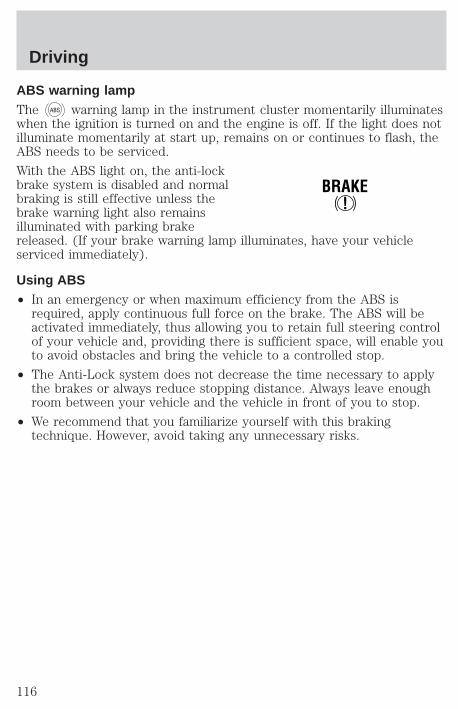
ABS warning lampThe ABS warning lamp in the instrument cluster momentarily illuminateswhen the ignition is turned on and the engine is off. If the light does notilluminate momentarily at start up, remains on or continues to flash, theABS needs to be serviced.
With the ABS light on, the anti-lockbrake system is disabled and normalbraking is still effective unless thebrake warning light also remainsilluminated with parking brakereleased. (If your brake warning lamp illuminates, have your vehicleserviced immediately).
Using ABS• In an emergency or when maximum efficiency from the ABS is
required, apply continuous full force on the brake. The ABS will beactivated immediately, thus allowing you to retain full steering controlof your vehicle and, providing there is sufficient space, will enable youto avoid obstacles and bring the vehicle to a controlled stop.
• The Anti-Lock system does not decrease the time necessary to applythe brakes or always reduce stopping distance. Always leave enoughroom between your vehicle and the vehicle in front of you to stop.
• We recommend that you familiarize yourself with this brakingtechnique. However, avoid taking any unnecessary risks.
!BRAKE
Driving
116
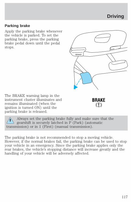
Parking brakeApply the parking brake wheneverthe vehicle is parked. To set theparking brake, press the parkingbrake pedal down until the pedalstops.
The BRAKE warning lamp in theinstrument cluster illuminates andremains illuminated (when theignition is turned ON) until theparking brake is released.
Always set the parking brake fully and make sure that thegearshift is securely latched in P (Park) (automatic
transmission) or in 1 (First) (manual transmission).
The parking brake is not recommended to stop a moving vehicle.However, if the normal brakes fail, the parking brake can be used to stopyour vehicle in an emergency. Since the parking brake applies only therear brakes, the vehicle’s stopping distance will increase greatly and thehandling of your vehicle will be adversely affected.
BRAKE
HOOD
!BRAKE
Driving
117
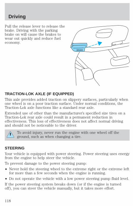
Pull the release lever to release thebrake. Driving with the parkingbrake on will cause the brakes towear out quickly and reduce fueleconomy.
TRACTION-LOK AXLE (IF EQUIPPED)This axle provides added traction on slippery surfaces, particularly whenone wheel is on a poor traction surface. Under normal conditions, theTraction-Lok axle functions like a standard rear axle.
Extended use of other than the manufacturer’s specified size tires on aTraction-Lok rear axle could result in a permanent reduction ineffectiveness. This loss of effectiveness does not affect normal drivingand should not be noticeable to the driver.
To avoid injury, never run the engine with one wheel off theground, such as when changing a tire.
STEERINGYour vehicle is equipped with power steering. Power steering uses energyfrom the engine to help steer the vehicle.
To prevent damage to the power steering pump:
• Never hold the steering wheel to the extreme right or the extreme leftfor more than a few seconds when the engine is running.
• Do not operate the vehicle with a low power steering pump fluid level.
If the power steering system breaks down (or if the engine is turnedoff), you can steer the vehicle manually, but it takes more effort.
BRAKE
HOOD
Driving
118
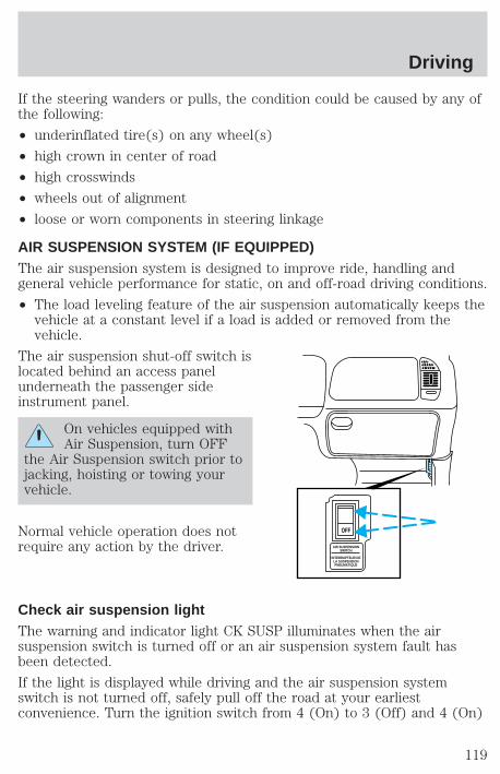
If the steering wanders or pulls, the condition could be caused by any ofthe following:
• underinflated tire(s) on any wheel(s)
• high crown in center of road
• high crosswinds
• wheels out of alignment
• loose or worn components in steering linkage
AIR SUSPENSION SYSTEM (IF EQUIPPED)The air suspension system is designed to improve ride, handling andgeneral vehicle performance for static, on and off-road driving conditions.
• The load leveling feature of the air suspension automatically keeps thevehicle at a constant level if a load is added or removed from thevehicle.
The air suspension shut-off switch islocated behind an access panelunderneath the passenger sideinstrument panel.
On vehicles equipped withAir Suspension, turn OFF
the Air Suspension switch prior tojacking, hoisting or towing yourvehicle.
Normal vehicle operation does notrequire any action by the driver.
Check air suspension lightThe warning and indicator light CK SUSP illuminates when the airsuspension switch is turned off or an air suspension system fault hasbeen detected.
If the light is displayed while driving and the air suspension systemswitch is not turned off, safely pull off the road at your earliestconvenience. Turn the ignition switch from 4 (On) to 3 (Off) and 4 (On)
AIR SUSPENSIONSWITCH
INTERRUPTEUR DELA SUSPENSIONPNEUMATIQUE
OFF
Driving
119
again. If the warning light reappears, turn the air suspension switch offand have the vehicle serviced by a dealer or qualified service technician.
If the vehicle is loaded beyond the recommended maximum payload, theCK SUSP light may illuminate. To correct this condition, remove orredistribute the payload according to the recommended requirementsand follow the procedure outlined above.
AUTOMATIC TRANSMISSION OPERATION (IF EQUIPPED)
Brake-shift interlockThis vehicle is equipped with a brake-shift interlock feature that preventsthe gearshift from being moved from P (Park) unless the brake pedal isdepressed.
If you cannot move the gearshift out of P (Park) with the brake pedaldepressed:
1. Apply the parking brake, turn ignition key to LOCK, then remove thekey.
2. Insert the key and turn it to OFF. Apply the brake pedal and shift to N(Neutral).
3. Start the vehicle.
If it is necessary to use the above procedure to move the gearshift, it ispossible that a fuse has blown or the vehicle’s brakelamps are notoperating properly. Refer to Fuses and relays in the Roadsideemergencies chapter.
Do not drive your vehicle until you verify that the brakelampsare working.
If your vehicle gets stuck in mud or snow it may be rocked out byshifting from forward and reverse gears, stopping between shifts, in asteady pattern. Press lightly on the accelerator in each gear.
Do not rock the vehicle for more than a few minutes. Thetransmission and tires may be damaged or the engine mayoverheat.
Always set the parking brake fully and make sure the gearshift islatched in P (Park). Turn off the ignition whenever you leave
your vehicle.
Driving
120

If the parking brake is fully released, but the brake warning lampremains illuminated, the brakes may not be working properly.
See your dealer or a qualified service technician.
Driving with a 4–speed automatic transmission
Understanding gearshift positionsPull the gearshift lever towards you and downward to move theautomatic gearshift.
Hold the brake pedal down while you move the gearshift leverfrom P (Park) to another position. If you do not hold the brake
pedal down, your vehicle may move unexpectedly and injure someone.
P (Park)Always come to a complete stopbefore shifting into P (Park). Makesure the gearshift is securely latchedin P (Park). This position locks thetransmission and prevents the rearwheels from turning.
Always set the parking brake fully and make sure the gearshift issecurely latched in P (Park).
Never leave your vehicle unattended while it is running.
R (Reverse)With the gearshift in R (Reverse),the vehicle will move backward.Always come to a complete stopbefore shifting into and out of R(Reverse).
Driving
121
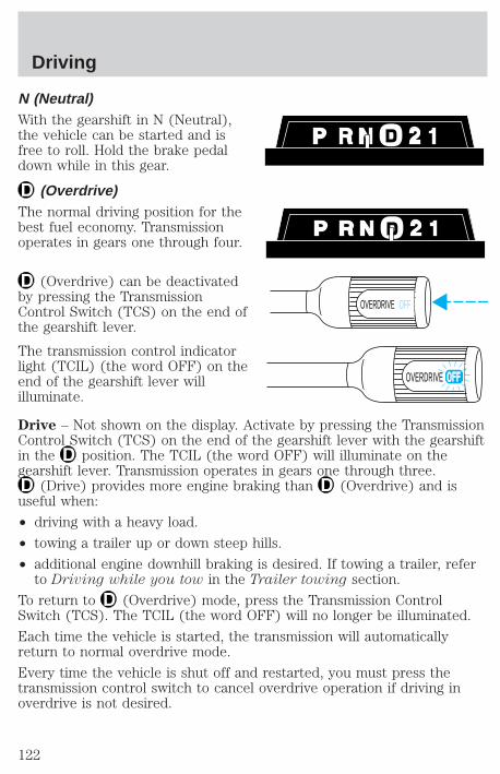
N (Neutral)With the gearshift in N (Neutral),the vehicle can be started and isfree to roll. Hold the brake pedaldown while in this gear.
(Overdrive)The normal driving position for thebest fuel economy. Transmissionoperates in gears one through four.
(Overdrive) can be deactivatedby pressing the TransmissionControl Switch (TCS) on the end ofthe gearshift lever.
The transmission control indicatorlight (TCIL) (the word OFF) on theend of the gearshift lever willilluminate.
Drive – Not shown on the display. Activate by pressing the TransmissionControl Switch (TCS) on the end of the gearshift lever with the gearshiftin the position. The TCIL (the word OFF) will illuminate on thegearshift lever. Transmission operates in gears one through three.
(Drive) provides more engine braking than (Overdrive) and isuseful when:
• driving with a heavy load.
• towing a trailer up or down steep hills.
• additional engine downhill braking is desired. If towing a trailer, referto Driving while you tow in the Trailer towing section.
To return to (Overdrive) mode, press the Transmission ControlSwitch (TCS). The TCIL (the word OFF) will no longer be illuminated.
Each time the vehicle is started, the transmission will automaticallyreturn to normal overdrive mode.
Every time the vehicle is shut off and restarted, you must press thetransmission control switch to cancel overdrive operation if driving inoverdrive is not desired.
OVERDRIVE OFF
OVERDRIVE
Driving
122
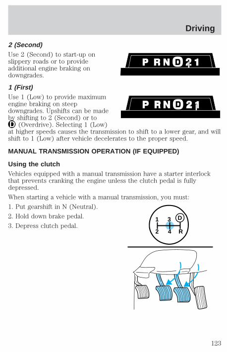
2 (Second)Use 2 (Second) to start-up onslippery roads or to provideadditional engine braking ondowngrades.
1 (First)Use 1 (Low) to provide maximumengine braking on steepdowngrades. Upshifts can be madeby shifting to 2 (Second) or to
(Overdrive). Selecting 1 (Low)at higher speeds causes the transmission to shift to a lower gear, and willshift to 1 (Low) after vehicle decelerates to the proper speed.
MANUAL TRANSMISSION OPERATION (IF EQUIPPED)
Using the clutchVehicles equipped with a manual transmission have a starter interlockthat prevents cranking the engine unless the clutch pedal is fullydepressed.
When starting a vehicle with a manual transmission, you must:
1. Put gearshift in N (Neutral).
2. Hold down brake pedal.
3. Depress clutch pedal.1
2 4 R
3 D
Driving
123
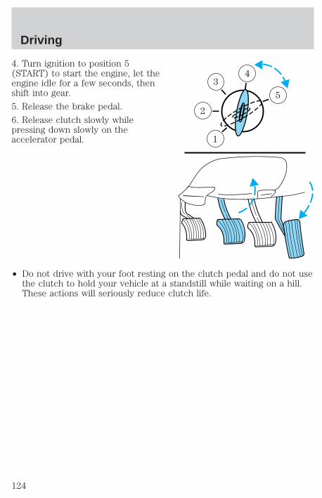
4. Turn ignition to position 5(START) to start the engine, let theengine idle for a few seconds, thenshift into gear.
5. Release the brake pedal.
6. Release clutch slowly whilepressing down slowly on theaccelerator pedal.
• Do not drive with your foot resting on the clutch pedal and do not usethe clutch to hold your vehicle at a standstill while waiting on a hill.These actions will seriously reduce clutch life.
5
43
2
1
Driving
124
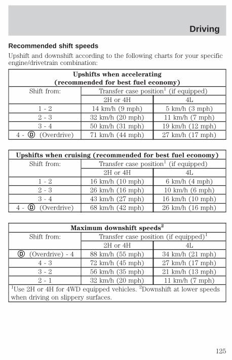
Recommended shift speedsUpshift and downshift according to the following charts for your specificengine/drivetrain combination:
Upshifts when accelerating
(recommended for best fuel economy)
Shift from: Transfer case position1 (if equipped)2H or 4H 4L
1 - 2 14 km/h (9 mph) 5 km/h (3 mph)2 - 3 32 km/h (20 mph) 11 km/h (7 mph)3 - 4 50 km/h (31 mph) 19 km/h (12 mph)
4 - D (Overdrive) 71 km/h (44 mph) 27 km/h (17 mph)
Upshifts when cruising (recommended for best fuel economy)
Shift from: Transfer case position1 (if equipped)2H or 4H 4L
1 - 2 16 km/h (10 mph) 6 km/h (4 mph)2 - 3 26 km/h (16 mph) 10 km/h (6 mph)3 - 4 43 km/h (27 mph) 16 km/h (10 mph)
4 - D (Overdrive) 68 km/h (42 mph) 26 km/h (16 mph)
Maximum downshift speeds2
Shift from: Transfer case position (if equipped)1
2H or 4H 4LD (Overdrive) - 4 88 km/h (55 mph) 34 km/h (21 mph)
4 - 3 72 km/h (45 mph) 27 km/h (17 mph)3 - 2 56 km/h (35 mph) 21 km/h (13 mph)2 - 1 32 km/h (20 mph) 11 km/h (7 mph)
1Use 2H or 4H for 4WD equipped vehicles. 2Downshift at lower speedswhen driving on slippery surfaces.
Driving
125

Parking your vehicle1. Disengage the clutch, apply brakeand shift into N (Neutral).
2. Set parking brake.
3. Shift into 1 (First).
4. Turn the ignition key to position3 (OFF).
1
2 4 R
3 D
3
2
1
5
4
Driving
126
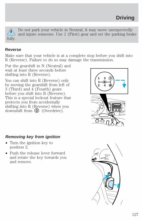
Do not park your vehicle in Neutral, it may move unexpectedlyand injure someone. Use 1 (First) gear and set the parking brake
fully.
ReverseMake sure that your vehicle is at a complete stop before you shift intoR (Reverse). Failure to do so may damage the transmission.
Put the gearshift in N (Neutral) andwait at least three seconds beforeshifting into R (Reverse).
You can shift into R (Reverse) onlyby moving the gearshift from left of3 (Third) and 4 (Fourth) gearsbefore you shift into R (Reverse).This is a special lockout feature thatprotects you from accidentallyshifting into R (Reverse) when youdownshift from D (Overdrive).
Removing key from ignition• Turn the ignition key to
position 2.
• Push the release lever forwardand rotate the key towards youand remove.
1 3
2 4 R
D
Driving
127
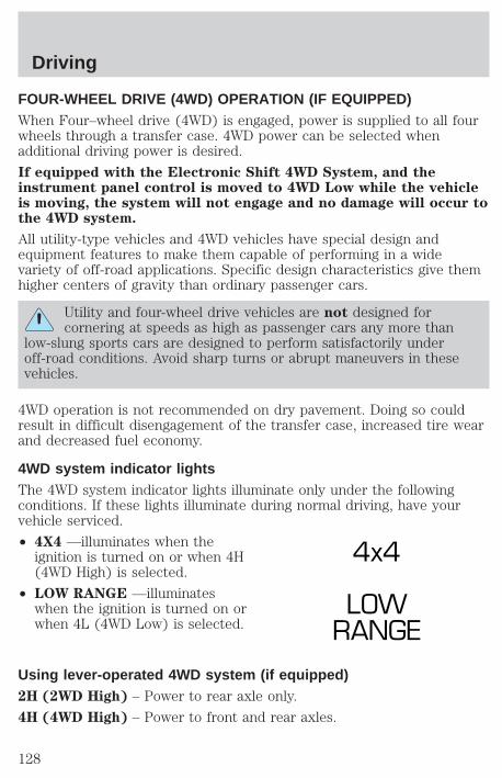
FOUR-WHEEL DRIVE (4WD) OPERATION (IF EQUIPPED)When Four–wheel drive (4WD) is engaged, power is supplied to all fourwheels through a transfer case. 4WD power can be selected whenadditional driving power is desired.
If equipped with the Electronic Shift 4WD System, and theinstrument panel control is moved to 4WD Low while the vehicleis moving, the system will not engage and no damage will occur tothe 4WD system.
All utility-type vehicles and 4WD vehicles have special design andequipment features to make them capable of performing in a widevariety of off-road applications. Specific design characteristics give themhigher centers of gravity than ordinary passenger cars.
Utility and four-wheel drive vehicles are not designed forcornering at speeds as high as passenger cars any more than
low-slung sports cars are designed to perform satisfactorily underoff-road conditions. Avoid sharp turns or abrupt maneuvers in thesevehicles.
4WD operation is not recommended on dry pavement. Doing so couldresult in difficult disengagement of the transfer case, increased tire wearand decreased fuel economy.
4WD system indicator lightsThe 4WD system indicator lights illuminate only under the followingconditions. If these lights illuminate during normal driving, have yourvehicle serviced.
• 4X4 —illuminates when theignition is turned on or when 4H(4WD High) is selected.
• LOW RANGE —illuminateswhen the ignition is turned on orwhen 4L (4WD Low) is selected.
Using lever-operated 4WD system (if equipped)2H (2WD High) – Power to rear axle only.
4H (4WD High) – Power to front and rear axles.
4x4
LOWRANGE
Driving
128
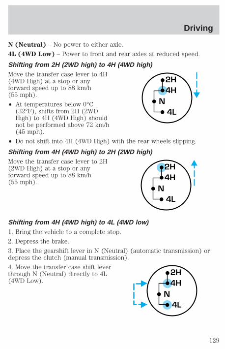
N (Neutral) – No power to either axle.
4L (4WD Low) – Power to front and rear axles at reduced speed.
Shifting from 2H (2WD high) to 4H (4WD high)Move the transfer case lever to 4H(4WD High) at a stop or anyforward speed up to 88 km/h(55 mph).
• At temperatures below 0°C(32°F), shifts from 2H (2WDHigh) to 4H (4WD High) shouldnot be performed above 72 km/h(45 mph).
• Do not shift into 4H (4WD High) with the rear wheels slipping.
Shifting from 4H (4WD high) to 2H (2WD high)Move the transfer case lever to 2H(2WD High) at a stop or anyforward speed up to 88 km/h(55 mph).
Shifting from 4H (4WD high) to 4L (4WD low)1. Bring the vehicle to a complete stop.
2. Depress the brake.
3. Place the gearshift lever in N (Neutral) (automatic transmission) ordepress the clutch (manual transmission).
4. Move the transfer case shift leverthrough N (Neutral) directly to 4L(4WD Low).
2H4H
4LN
2H4H
4LN
2H4H
4LN
Driving
129
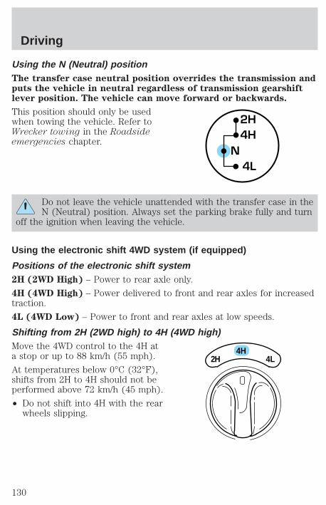
Using the N (Neutral) positionThe transfer case neutral position overrides the transmission andputs the vehicle in neutral regardless of transmission gearshiftlever position. The vehicle can move forward or backwards.
This position should only be usedwhen towing the vehicle. Refer toWrecker towing in the Roadsideemergencies chapter.
Do not leave the vehicle unattended with the transfer case in theN (Neutral) position. Always set the parking brake fully and turn
off the ignition when leaving the vehicle.
Using the electronic shift 4WD system (if equipped)
Positions of the electronic shift system2H (2WD High) – Power to rear axle only.
4H (4WD High) – Power delivered to front and rear axles for increasedtraction.
4L (4WD Low) – Power to front and rear axles at low speeds.
Shifting from 2H (2WD high) to 4H (4WD high)Move the 4WD control to the 4H ata stop or up to 88 km/h (55 mph).
At temperatures below 0°C (32°F),shifts from 2H to 4H should not beperformed above 72 km/h (45 mph).
• Do not shift into 4H with the rearwheels slipping.
2H4H
4LN
4H2H 4L
Driving
130

Shifting from 4H (4WD high) to 2H (2WD high)Move the 4WD control to 2H at anyforward speed.
Shifting between 4H (4WD high) and 4L (4WD low)1. Bring the vehicle to a stop.
2. Depress the brake.
3. Place the gearshift in N (Neutral) (automatic transmission) or depressthe clutch (manual transmission).
4. Move the 4WD control to the 4Hor 4L position.
Driving off-road with 4WDYour vehicle is specially equipped for driving on sand, snow, mud andrough terrain and has operating characteristics that are somewhatdifferent from conventional vehicles, both on and off the road.
Maintain steering wheel control at all times, especially in rough terrain.Since sudden changes in terrain can result in abrupt steering wheelmotion, make sure you grip the steering wheel from the outside. Do notgrip the spokes.
Drive cautiously to avoid vehicle damage from concealed objects such asrocks and stumps.
4H2H 4L
4H2H 4L
Driving
131
You should either know the terrain or examine maps of the area beforedriving. Map out your route before driving in the area. For moreinformation on driving off-road, read the “Four Wheeling” supplement inyour owner’s portfolio.
If your vehicle gets stuckIf the vehicle is stuck it may be rocked out by shifting from forward andreverse gears, stopping between shifts, in a steady pattern. Press lightlyon the accelerator in each gear.
Do not rock the vehicle for more than a few minutes. Thetransmission and tires may be damaged or the engine canoverheat.
Do not spin the wheels at over 56 km/h (35 mph). The tires mayfail and injure a passenger or bystander.
SandWhen driving over sand, try to keep all four wheels on the most solidarea of the trail. Do not reduce the tire pressures but shift to a lowergear and drive steadily through the terrain. Apply the accelerator slowlyand avoid spinning the wheels.
Mud and waterIf you must drive through high water, drive slowly. Traction or brakecapability may be limited.
When driving through water, determine the depth; avoid water higherthan the bottom of the hubs (if possible) and proceed slowly. If theignition system gets wet, the vehicle may stall.
Once through water, always try the brakes. Wet brakes do not stop thevehicle as effectively as dry brakes. Drying can be improved by movingyour vehicle slowly while applying light pressure on the brake pedal.
After driving through mud, clean off residue stuck to rotating driveshafts,halfshafts and tires. Excess mud stuck on tires and rotating driveshaftscauses an imbalance that could damage drive components.
If the transmission, transfer case or front axle are submerged in water,their fluids should be checked and changed, if necessary.
Water intrusion into the transmission may damage thetransmission.
Driving
132
Replace rear axle lubricant any time the axle has been submerged inwater. The rear axle does not normally require a lubricant change for thelife of the vehicle. Rear axle lubricant quantities are not to be checked orchanged unless a leak is suspected or repair is required.
Driving on hilly or sloping terrainWhen driving on a hill, avoid driving crosswise or turning on steepslopes. You could lose traction and slip sideways. Drive straight up,straight down or avoid the hill completely. Know the conditions on theother side of a hill before driving over the crest.
When climbing a steep hill, start in a lower gear rather than downshiftingto a lower gear from a higher gear once the ascent has started. Thisreduces strain on the engine and the possibility of stalling.
When descending a steep hill, avoid sudden braking. Shift to a lower gearwhen added engine braking is desired.
When speed control is on and you are driving uphill, your vehicle speedmay drop considerably, especially if you are carrying a heavy load.
If vehicle speed drops more than 16 km/h (10 mph), the speed controlwill cancel automatically. Resume speed with accelerator pedal.
If speed control cancels after climbing the hill, reset speed by pressingand holding the SET ACCEL button to resume speeds over 50 km/h(30 mph).
Automatic transmissions may shift frequently while driving up steepgrades. Eliminate frequent shifting by shifting out of (Overdrive) intoa lower gear.
Driving on snow and iceA 4WD vehicle has advantages over 2WD vehicles in snow and ice butcan skid like any other vehicle.
Avoid sudden applications of power and quick changes of direction onsnow and ice. Apply the accelerator slowly and steadily when startingfrom a full stop.
When braking, apply the brakes as you normally would. In order to allowthe anti-lock brake system (ABS) to operate properly, keep steadypressure on the brake pedal.
Allow more stopping distance and drive slower than usual. Considerusing one of the lower gears.
Driving
133
VEHICLE LOADINGBefore loading a vehicle, familiarize yourself with the following terms:
• Base Curb Weight : Weight of the vehicle including any standardequipment, fluids, lubricants, etc. It does not include passengers oraftermarket equipment.
• Payload : Combined maximum allowable weight of cargo, passengersand optional equipment. The payload equals the gross vehicle weightrating minus base curb weight.
• GVW (Gross Vehicle Weight) : Base curb weight plus payloadweight. The GVW is not a limit or a specification.
• GVWR (Gross Vehicle Weight Rating) : Maximum total weight ofthe base vehicle, passengers, optional equipment and cargo. TheGVWR is specific to each vehicle and is listed on the SafetyCompliance Label on the driver’s door pillar.
• GAWR (Gross Axle Weight Rating) : Carrying capacity for eachaxle system. The GAWR is specific to each vehicle and is listed on theSafety Compliance Label on the driver’s door pillar.
• GCW (Gross Combined Weight) : The combined weight of thetowing vehicle (including passengers and cargo) and the trailer.
• GCWR (Gross Combined Weight Rating) : Maximum combinedweight of towing vehicle (including passengers and cargo) and thetrailer. The GCWR indicates the maximum loaded weight that thevehicle is designed to tow.
• Maximum Trailer Weight Rating : Maximum weight of a trailer thevehicle is permitted to tow. The maximum trailer weight rating isdetermined by subtracting the vehicle curb weight for eachengine/transmission combination, any required option weight for trailertowing and the weight of the driver from the GCWR for the towingvehicle.
• Maximum Trailer Weight : maximum weight of a trailer the loadedvehicle (including passengers and cargo) is permitted to tow. It isdetermined by subtracting the weight of the loaded trailer towingvehicle from the GCWR for the towing vehicle.
• Trailer Weight Range : Specified weight range that the trailer mustfall within that ranges from zero to the maximum trailer weight rating.
Remember to figure in the tongue load of your loaded trailer whenfiguring the total weight.
Driving
134

Do not exceed the GVWR or the GAWR specified on the SafetyCompliance Certification Label.
Do not use replacement tires with lower load carrying capacities than theoriginals because they may lower the vehicle’s GVWR and GAWRlimitations. Replacement tires with a higher limit than the originals donot increase the GVWR and GAWR limitations.
The Certification Label, found on the inside pillar of the driver’s door,lists several important vehicle weight rating limitations. Before addingany additional equipment, refer to these limitations. If you are addingweight to the front of your vehicle, (potentially including weight addedto the cab), the weight added should not exceed the Front Axle ReserveCapacity (FARC). Additional frontal weight may be added to the frontaxle reserve capacity provided you limit your payload in other ways (i.e.restrict the number of passengers or amount of cargo carried).
You may add equipment throughout your vehicle if the total weightadded is equal to or less than the Total Axle Reserve Capacity (TARC)weight. You should NEVER exceed the Total Axle Reserve Capacity.
Always ensure that the weight of passengers, cargo and equipment beingcarried is within the weight limitations that have been established foryour vehicle including both Gross Vehicle Weight and Front and RearGross Axle Weight Rating limits. Under no circumstance should theselimitations be exceeded. Exceeding any vehicle weight rating limitationcould result in serious damage to the vehicle and/or personal injury.
Calculating the load your vehicle can carry/tow1. Use the appropriate maximum gross combined weight rating (GCWR)chart to find the maximum GCWR for your type engine and rear axleratio.
2. Weigh your vehicle as you customarily operate the vehicle withoutcargo. To obtain correct weights, try taking your vehicle to a shippingcompany or an inspection station for trucks.
3. Subtract your loaded vehicle weight from the maximum GCWR on thefollowing charts. This is the maximum trailer weight your vehicle can towand must fall below the maximum shown under maximum trailer weighton the chart.
Driving
135
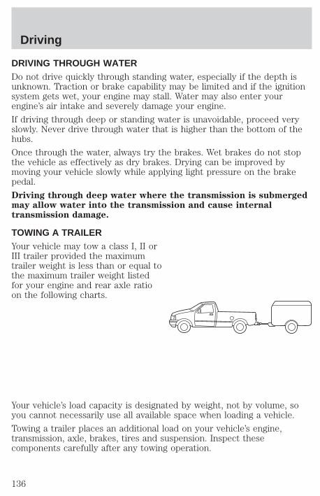
DRIVING THROUGH WATERDo not drive quickly through standing water, especially if the depth isunknown. Traction or brake capability may be limited and if the ignitionsystem gets wet, your engine may stall. Water may also enter yourengine’s air intake and severely damage your engine.
If driving through deep or standing water is unavoidable, proceed veryslowly. Never drive through water that is higher than the bottom of thehubs.
Once through the water, always try the brakes. Wet brakes do not stopthe vehicle as effectively as dry brakes. Drying can be improved bymoving your vehicle slowly while applying light pressure on the brakepedal.
Driving through deep water where the transmission is submergedmay allow water into the transmission and cause internaltransmission damage.
TOWING A TRAILERYour vehicle may tow a class I, II orIII trailer provided the maximumtrailer weight is less than or equal tothe maximum trailer weight listedfor your engine and rear axle ratioon the following charts.
Your vehicle’s load capacity is designated by weight, not by volume, soyou cannot necessarily use all available space when loading a vehicle.
Towing a trailer places an additional load on your vehicle’s engine,transmission, axle, brakes, tires and suspension. Inspect thesecomponents carefully after any towing operation.
Driving
136
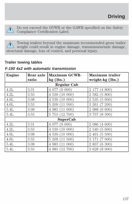
Do not exceed the GVWR or the GAWR specified on the SafetyCompliance Certification Label.
Towing trailers beyond the maximum recommended gross trailerweight could result in engine damage, transmission/axle damage,
structural damage, loss of control, and personal injury.
Trailer towing tables
F-150 4x2 with automatic transmission
Engine Rear axle
ratio
Maximum GCWR-
kg (lbs.)
Maximum trailer
weight-kg (lbs.)
Regular Cab
4.2L 3.31 4 077 (9 000) 2 177 (4 800)4.2L 3.55 4 530 (10 000) 2 582 (5 800)4.6L 3.08 4 530 (10 000) 2 535 (5 600)4.6L 3.55 5 209 (11 500) 3 261 (7 200)5.4L 3.08 4 983 (11 000) 2 988 (6 600)5.4L 3.55 5 753 (12 700) 3 757 (8 300)
SuperCab
4.2L 3.31 4 077 (9 000) 2 086 (4 600)4.2L 3.55 4 530 (10 000) 2 540 (5 600)4.6L 3.08 4 530 (10 000) 2 491 (5 500)4.6L 3.55 5 209 (11 500) 3 171 (7 000)5.4L 3.08 4 983 (11 000) 2 857 (6 300)5.4L 3.55 4 983 (12 700) 3 628 (8 000)
Driving
137
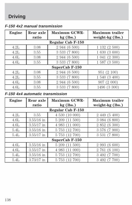
F-150 4x2 manual transmission
Engine Rear axle
ratio
Maximum GCWR-
kg (lbs.)
Maximum trailer
weight-kg (lbs.)
Regular Cab F-150
4.2L 3.08 2 944 (6 500) 1 132 (2 500)4.2L 3.55 3 533 (7 800) 1 630 (3 600)4.6L 3.08 2 944 (6 500) 1 041 (2 300)4.6L 3.55 3 533 (7 800) 1 587 (3 500)
SuperCab F-150
4.2L 3.08 2 944 (6 500) 951 (2 100)4.2L 3.55 3 533 (7 800) 1 540 (3 400)4.6L 3.08 2 944 (6 500) 907 (2 000)4.6L 3.55 3 533 (7 800) 1496 (3 300)
F-150 4x4 automatic transmission
Engine Rear axle
ratio
Maximum GCWR-
kg (lbs.)
Maximum trailer
weight-kg (lbs.)
Regular Cab F-150
4.2L 3.55 4 530 (10 000) 2 449 (5 400)4.6L 3.55/16 in 5 209 (11 500) 3 084 (6 800)4.6L 3.55/17 in 4 983 (11 000) 2 852 (6 300)5.4L 3.55/16 in 5 753 (12 700) 3 576 (7 900)5.4L 3.55/17 in 5 753 (12 700) 3 531 (7 800)
SuperCab F-150
4.6L 3.55/16 in 5 209 (11 500) 2 993 (6 600)4.6L 3.55/17 in 4 983 (11 000) 2 761 (6 100)5.4L 3.55/16 in 5 753 (12 700) 3 492 (7 700)5.4L 3.73/17 in 5 753 (12 700) 3 492 (7 700)
Driving
138

F-150 4x4 manual transmission
Trailer towing table (F-150 4x4 manual transmission)
Engine Rear axle
ratio
Maximum GCWR-
kg (lbs.)
Maximum trailer
weight-kg (lbs.)
Regular Cab F-150
4.2L 3.31 2 944 (6 500) 861 (1 900)4.2L 3.55 3 533 (7 800) 1 451 (3 200)4.6L 3.08 2 944 (6 500) 816 (1 800)4.6L 3.55 3 533 (7 800) 1 406 (3 100)
SuperCab F-150
4.6L 3.08 2 944 (6 500) 771 (1 700)4.6L 3.55 3 533 (7 800) 1 360 (3 000)
F-250 4x2 automatic transmission
Engine Rear axle
ratio
Maximum GCWR-
kg (lbs.)
Maximum trailer
weight-kg (lbs.)
Regular Cab F-250
4.6L 3.31 4 756 (10 500) 2 671 (5 900)4.6L 3.73 5 436 (12 000) 3 350 (7 400)5.4L 3.31 5 436 (12 000) 3 305 (7 300)5.4L 3.73 6 115 (13 500) 3 938 (8 700)
SuperCab F-250
4.6L 3.31 4 756 (10 500) 2 625 (5 800)4.6L 3.73 5 436 (12 000) 3 305 (7 300)5.4L 3.31 5 436 (12 000) 3 259 (7 200)5.4L 3.73 6 115 (13 500) 3 938 (8 700)
Driving
139
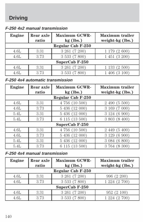
F-250 4x2 manual transmission
Engine Rear axle
ratio
Maximum GCWR-
kg (lbs.)
Maximum trailer
weight-kg (lbs.)
Regular Cab F-250
4.6L 3.31 3 261 (7 200) 1 179 (2 600)4.6L 3.73 3 533 (7 800) 1 451 (3 200)
SuperCab F-250
4.6L 3.31 3 261 (7 200) 1 133 (2 500)4.6L 3.73 3 533 (7 800) 1 406 (3 100)
F-250 4x4 automatic transmission
Engine Rear axle
ratio
Maximum GCWR-
kg (lbs.)
Maximum trailer
weight-kg (lbs.)
Regular Cab F-250
4.6L 3.31 4 756 (10 500) 2 490 (5 500)4.6L 3.73 5 436 (12 000) 3 169 (7 000)5.4L 3.31 5 436 (12 000) 3 124 (6 900)5.4L 3.73 6 115 (13 500) 3 803 (8 400)
SuperCab F-250
4.6L 3.31 4 756 (10 500) 2 449 (5 400)4.6L 3.73 5 436 (12 000) 3 129 (6 900)5.4L 3.31 5 436 (12 000) 3 084 (6 800)5.4L 3.73 6 115 (13 500) 3 764 (8 300)
F-250 4x4 manual transmission
Engine Rear axle
ratio
Maximum GCWR-
kg (lbs.)
Maximum trailer
weight-kg (lbs.)
Regular Cab F-250
4.6L 3.31 3 261 (7 200) 996 (2 200)4.6L 3.73 3 533 (7 800) 1 224 (2 700)
SuperCab F-250
4.6L 3.31 3 261 (7 200) 952 (2 100)4.6L 3.73 3 533 (7 800) 1 224 (2 700)
Driving
140
Trailer frontal area considerations:
• Not to exceed towing vehicle front area without Class III trailer towingpackage
• Not to exceed 5.52 square meters (60 square feet) with Class IIItrailer towing package
Preparing to towUse the proper equipment for towing a trailer, and make sure it isproperly attached to your vehicle. See your dealer or a reliable trailerdealer if you require assistance.
HitchesDo not use hitches that clamp onto the vehicle’s bumper or attach to theaxle. You must distribute the load in your trailer so that 10% of the totalweight of the trailer is on the tongue.
Load equalizing hitchWhen hooking up a trailer using a load equalizing hitch, always use thefollowing procedure:
1. Park the unloaded vehicle on a level surface. With the ignition on andall doors closed, allow the vehicle to stand for several minutes so that itcan level.
2. Turn the air suspension (if equipped) control to OFF.
3. Measure the height of a reference point on the front and rear bumpersat the center of the vehicle.
4. Attach the trailer to the vehicle and adjust the hitch equalizers so thatthe front bumper height is within 0–13 mm (0.5 in) of the referencepoint. After proper adjustment, the rear bumper should be no higherthan in Step 3.
5. Turn the air suspension (if equipped) control to ON.
Adjusting an equalizing hitch so the rear bumper of the vehicleis lower or higher than it was unloaded will defeat the function
of the load equalizing hitch and may cause unpredictable handling.
Driving
141
Safety chainsAlways connect the trailer’s safety chains to the vehicle. To connect thetrailer’s safety chains, cross the chains under the trailer tongue and allowslack for turning corners.
If you use a rental trailer, follow the instructions that the rental agencygives to you.
Do not attach safety chains to the bumper.
Trailer brakesElectric brakes and manual, automatic or surge-type brakes are safe ifinstalled properly and adjusted to the manufacturer’s specifications. Thetrailer brakes must meet local and Federal regulations.
Do not connect a trailer’s hydraulic brake system directly to yourvehicle’s brake system. Your vehicle may not have enough
braking power and your chances of having a collision greatly increase.
The braking system of the tow vehicle is rated for operation at theGVWR not GCWR.
Trailer lampsTrailer lamps are required on most towed vehicles. Make sure yourtrailer lamps conform to local and Federal regulations. See your dealer ortrailer rental agency for proper instructions and equipment for hookingup trailer lamps.
Using a step bumperThe rear bumper is equipped with an integral hitch and requires only aball with a 25.4 mm (one inch) shank diameter. The bumper has a 2 270kg (5 000 lb.) trailer weight and 227 kg (500 lb.) tongue weightcapability.
If it is necessary to relocate the trailer hitch ball position, aframe-mounted trailer hitch must be installed.
Driving while you towDo not drive faster than 88 km/h (55 mph) when towing a trailer.
Speed control may shut off if you are towing on long, steep grades.
Driving
142
When towing a trailer:
• Use a lower gear when towing up or down steep hills. This willeliminate excessive downshifting and upshifting for optimum fueleconomy and transmission cooling.
• Anticipate stops and brake gradually.
Exceeding the GCWR rating may cause internal transmissiondamage and void your warranty coverage.
Servicing after towingIf you tow a trailer for long distances, your vehicle will require morefrequent service intervals. Refer to your Scheduled Maintenance guidefor more information.
Trailer towing tips• Practice turning, stopping and backing up in an area before starting on
a trip to get the feel of the vehicle trailer combination. When turning,make wider turns so the trailer wheels will clear curbs and otherobstacles.
• Allow more distance for stopping with a trailer attached.
• The trailer tongue weight should be 10–15% of the loaded trailerweight.
• After you have traveled 80 km (50 miles), thoroughly check yourhitch, electrical connections and trailer wheel lug nuts.
• When stopped in traffic for long periods of time in hot weather, placethe gearshift in P (Park) (automatic transmissions) or N (Neutral)(manual transmissions). This aids engine cooling and air conditionerefficiency.
• Vehicles with trailers should not be parked on a grade. If you mustpark on a grade, place wheel chocks under the trailer’s wheels.
Launching or retrieving a boatWhen backing down a ramp during boat launching or retrieval,
• Do not allow the static water level to rise above the bottom edge ofthe rear bumper and
• Do not allow waves to break higher than 15 cm (six inches) above thebottom edge of the rear bumper.
Driving
143
Exceeding these limits may allow water to enter critical vehiclecomponents, adversely affecting driveability, emissions, reliability andcausing internal transmission damage.
Replace the rear axle lubricant anytime the axle has been submerged inwater. Rear axle lubricant quantities are not to be checked or changedunless a leak is suspected or repair required.
Disconnect the wiring to the trailer before backing the trailer into thewater. Reconnect the wiring to the trailer after the trailer is removedfrom the water.
Recreational towing (all wheels on the ground)Follow these guidelines for your specific powertrain combination to towyour vehicle with all four wheels on the ground (such as behind arecreational vehicle).
These guidelines are designed to ensure that your transmission is notdamaged due to insufficient lubrication.
2WD (manual and automatic transmissions)1. Place transmission in N (Neutral).
2. Maximum speed is 56 km/h (35 mph).
3. Maximum distance is 80 km (50 miles).
If a distance of 80 km (50 miles) or a speed of 56 km/h (35 mph) mustbe exceeded, you must disconnect the rear driveshaft. With the reardriveshaft disconnected, the maximum speed is 88 km/h (55 mph) andthere are no mileage restrictions.
See your dealer for help with disconnecting the driveshaft.
4WD – Lever operated transfer case(manual and automatic transmissions)1. Place transmission in P (Park) (automatic transmission), or R(Reverse) (manual transmission). Engage the parking brake.
2. Shift the transfer case to N (Neutral).
3. Lockout the center disconnect by capping off one of the front axlevacuum motor lines. See your Ford dealer for assistance.
4. Vehicle speed should not exceed 88 km/h (55 mph) and there are nomileage restrictions.
Driving
144

4WD – Electronic shift transfer case1. Place transmission in N (Neutral).
2. Shift the transfer case to 2H (2WD high).
3. Lockout the center disconnect by capping off one of the front axlevacuum motor lines. See your dealer for assistance.
4. Maximum speed is 56 km/h (35 mph).
5. Maximum distance is 80 km (50 miles).
If a distance of 80 km (50 miles) or a speed of 56 km/h (35 mph) mustbe exceeded, you must disconnect the rear driveshaft. With the reardriveshaft disconnected, the maximum speed is 88 km/h (55 mph) andthere are no mileage restrictions.
See your dealer for help with disconnecting the driveshaft.
SNOWPLOWINGFord recommends the following specifications for low speed, personaluse snow removal:
• F-150/F–250 4WD Regular Cab long wheelbase
• 4.6L or 5.4L engine
• Heavy duty service package
• Super engine cooling
• Heavy duty front suspension package
• Automatic transmission with auxiliary automatic transmission fluidcooling
• All-terrain tires
Do not install a snowplow and plow with your vehicle until it has beendriven at least 800 km (500 miles).
Installing snowplowRead the following instructions before installing a snowplow:
• Front GAWR must not exceed 63% of the GVW. Add ballast weight tothe back of the vehicle, if necessary. Refer to the Safety ComplianceCertification Label to find Front GAWR.
Driving
145

• The Front Axle Accessory Reserve Capacity and the Total AccessoryReserve Capacity listed on the bottom right of the Safety ComplianceCertification Label will determine whether or not the addition of asnowplow will overload your vehicle.
• The weight of the snowplow and supporting components distributed tothe front axle must not exceed the front accessory reserve capacity.
• The total weight of the snowplow and aftermarket equipment mustnot exceed the Total Accessory Reserve Capacity.
• The weight of the installed snowplow and aftermarket equipment mustnot load the vehicle beyond the GAWR (front/rear) and GVWR listedon the Safety Compliance Certification Label.
• The total weight of the snowplow and aftermarket equipment must beconsidered part of the payload and must not exceed the GrossCombined Weight Rating (GCWR) for towing.
• Federal and most local regulations require additional exterior lampsfor snowplow-equipped vehicles. Consult your dealer for additionalinformation.
• After installing a snowplow to the vehicle, ensure the vehicle’s fronttoe alignment and front ride height are within specification (reset ifrequired). These specifications are located in the vehicle’s WorkshopManual. Adherence to the toe, tire pressures and ride heightspecification is important for proper tire wear, ride, handling andheadlight aim. Also, maintain the engine oil and transmission fluidchange intervals following the severe duty schedule.
Do not exceed the GVWR or the GAWR specified on the SafetyCompliance Certification Label.
Removing snowplowRead the following instructions before removing a snowplow:
• After removing a snowplow from the vehicle, ensure the vehicle’s fronttoe alignment and front ride height are within specification (reset ifrequired). These specifications are located in the vehicle’s WorkshopManual. Adherence to the toe and ride height specification isimportant for proper tire wear, ride, handling and headlight aim.
Driving
146
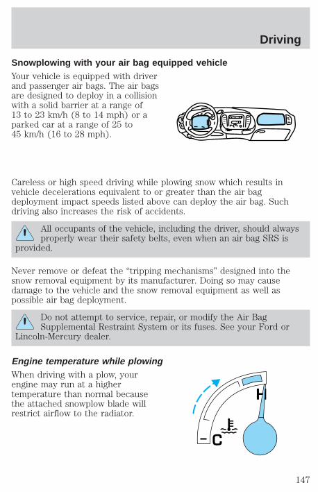
Snowplowing with your air bag equipped vehicleYour vehicle is equipped with driverand passenger air bags. The air bagsare designed to deploy in a collisionwith a solid barrier at a range of13 to 23 km/h (8 to 14 mph) or aparked car at a range of 25 to45 km/h (16 to 28 mph).
Careless or high speed driving while plowing snow which results invehicle decelerations equivalent to or greater than the air bagdeployment impact speeds listed above can deploy the air bag. Suchdriving also increases the risk of accidents.
All occupants of the vehicle, including the driver, should alwaysproperly wear their safety belts, even when an air bag SRS is
provided.
Never remove or defeat the “tripping mechanisms” designed into thesnow removal equipment by its manufacturer. Doing so may causedamage to the vehicle and the snow removal equipment as well aspossible air bag deployment.
Do not attempt to service, repair, or modify the Air BagSupplemental Restraint System or its fuses. See your Ford or
Lincoln-Mercury dealer.
Engine temperature while plowingWhen driving with a plow, yourengine may run at a highertemperature than normal becausethe attached snowplow blade willrestrict airflow to the radiator.
H
C
Driving
147
If you are driving more than 24 km (15 miles) at temperatures abovefreezing, angle the plow blade either full left or full right to providemaximum airflow to the radiator.
If you are driving less than 24 km (15 miles) at speeds up to 64 km/h(40 mph) in cold weather, you will not need to worry about bladeposition to provide maximum airflow.
Transmission operation while plowing• Shift transfer case to 4L (4WD Low) when plowing in small areas at
speeds below 8 km/h (5 mph).
• Shift transfer case to 4H (4WD High) when plowing larger areas orlight snow at higher speeds. Do not exceed 24 km/h (15 mph).
• Do not shift the transmission from a forward gear to R (Reverse) untilthe engine is at idle and the wheels are stopped.
• If the vehicle is stuck, shift the transmission in a steady motionbetween forward and reverse gears. Do not rock the vehicle for morethan a few minutes. The transmission and tires may be damaged orthe engine can overheat.
Do not spin the wheels at over 35 mph (55 km/h). The tires mayfail and injure a passenger or bystander.
Driving
148
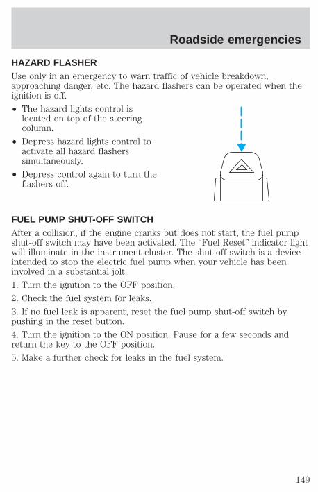
HAZARD FLASHERUse only in an emergency to warn traffic of vehicle breakdown,approaching danger, etc. The hazard flashers can be operated when theignition is off.
• The hazard lights control islocated on top of the steeringcolumn.
• Depress hazard lights control toactivate all hazard flasherssimultaneously.
• Depress control again to turn theflashers off.
FUEL PUMP SHUT-OFF SWITCHAfter a collision, if the engine cranks but does not start, the fuel pumpshut-off switch may have been activated. The “Fuel Reset” indicator lightwill illuminate in the instrument cluster. The shut-off switch is a deviceintended to stop the electric fuel pump when your vehicle has beeninvolved in a substantial jolt.
1. Turn the ignition to the OFF position.
2. Check the fuel system for leaks.
3. If no fuel leak is apparent, reset the fuel pump shut-off switch bypushing in the reset button.
4. Turn the ignition to the ON position. Pause for a few seconds andreturn the key to the OFF position.
5. Make a further check for leaks in the fuel system.
Roadside emergencies
149
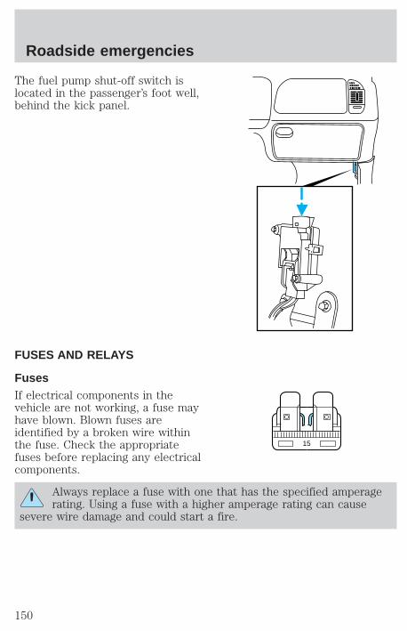
The fuel pump shut-off switch islocated in the passenger’s foot well,behind the kick panel.
FUSES AND RELAYS
FusesIf electrical components in thevehicle are not working, a fuse mayhave blown. Blown fuses areidentified by a broken wire withinthe fuse. Check the appropriatefuses before replacing any electricalcomponents.
Always replace a fuse with one that has the specified amperagerating. Using a fuse with a higher amperage rating can cause
severe wire damage and could start a fire.
15
Roadside emergencies
150
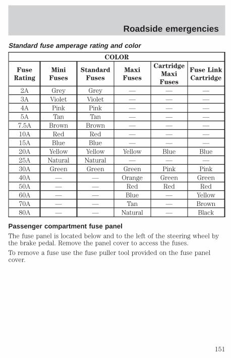
Standard fuse amperage rating and color
COLOR
Fuse
Rating
Mini
Fuses
Standard
Fuses
Maxi
Fuses
Cartridge
Maxi
Fuses
Fuse Link
Cartridge
2A Grey Grey — — —3A Violet Violet — — —4A Pink Pink — — —5A Tan Tan — — —
7.5A Brown Brown — — —10A Red Red — — —15A Blue Blue — — —20A Yellow Yellow Yellow Blue Blue25A Natural Natural — — —30A Green Green Green Pink Pink40A — — Orange Green Green50A — — Red Red Red60A — — Blue — Yellow70A — — Tan — Brown80A — — Natural — Black
Passenger compartment fuse panelThe fuse panel is located below and to the left of the steering wheel bythe brake pedal. Remove the panel cover to access the fuses.
To remove a fuse use the fuse puller tool provided on the fuse panelcover.
Roadside emergencies
151
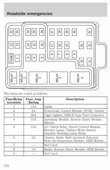
The fuses are coded as follows.
Fuse/RelayLocation
Fuse AmpRating
Description
1 15A Audio2 5A Powertrain Control Module (PCM), Cluster3 20A Cigar Lighter, OBD-II Scan Tool Connector4 15A Autolamp Module, Remote Entry Module,
Mirrors5 15A AC Clutch Relay, Speed Control Module,
Reverse Lamp, Climate Mode Switch,Daytime Running Lamp Relay
6 5A Cluster, Brake Shift Interlock Solenoid,Rear Air Suspension Module, GEM Module
7 — Not Used8 5A Radio, Remote Entry Module, GEM Module9 — Not Used
FUS
E1
1222
213
23
617
27
718
28
819
29
930
20
3121
1110R
ELA
Y5
RE
LAY
4
RE
LAY
3
RE
LAY
2
RE
LAY
1
314
24
415
25
516
26
Roadside emergencies
152
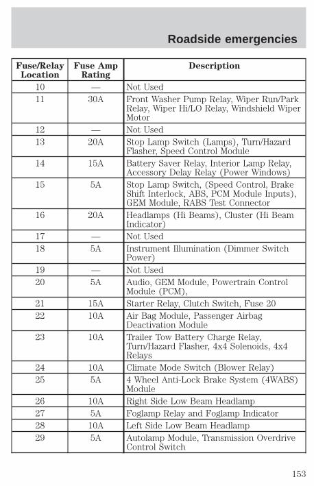
Fuse/RelayLocation
Fuse AmpRating
Description
10 — Not Used11 30A Front Washer Pump Relay, Wiper Run/Park
Relay, Wiper Hi/LO Relay, Windshield WiperMotor
12 — Not Used13 20A Stop Lamp Switch (Lamps), Turn/Hazard
Flasher, Speed Control Module14 15A Battery Saver Relay, Interior Lamp Relay,
Accessory Delay Relay (Power Windows)15 5A Stop Lamp Switch, (Speed Control, Brake
Shift Interlock, ABS, PCM Module Inputs),GEM Module, RABS Test Connector
16 20A Headlamps (Hi Beams), Cluster (Hi BeamIndicator)
17 — Not Used18 5A Instrument Illumination (Dimmer Switch
Power)19 — Not Used20 5A Audio, GEM Module, Powertrain Control
Module (PCM),21 15A Starter Relay, Clutch Switch, Fuse 2022 10A Air Bag Module, Passenger Airbag
Deactivation Module23 10A Trailer Tow Battery Charge Relay,
Turn/Hazard Flasher, 4x4 Solenoids, 4x4Relays
24 10A Climate Mode Switch (Blower Relay)25 5A 4 Wheel Anti-Lock Brake System (4WABS)
Module26 10A Right Side Low Beam Headlamp27 5A Foglamp Relay and Foglamp Indicator28 10A Left Side Low Beam Headlamp29 5A Autolamp Module, Transmission Overdrive
Control Switch
Roadside emergencies
153
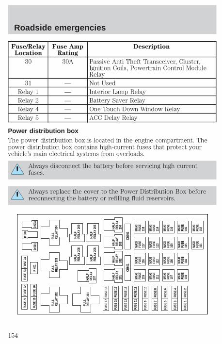
Fuse/RelayLocation
Fuse AmpRating
Description
30 30A Passive Anti Theft Transceiver, Cluster,Ignition Coils, Powertrain Control ModuleRelay
31 — Not UsedRelay 1 — Interior Lamp RelayRelay 2 — Battery Saver RelayRelay 4 — One Touch Down Window RelayRelay 5 — ACC Delay Relay
Power distribution boxThe power distribution box is located in the engine compartment. Thepower distribution box contains high-current fuses that protect yourvehicle’s main electrical systems from overloads.
Always disconnect the battery before servicing high currentfuses.
Always replace the cover to the Power Distribution Box beforereconnecting the battery or refilling fluid reservoirs.
MAX
IFU
SE11
5
MAX
IFU
SE11
6
MAX
IFU
SE11
7
MAX
IFU
SE11
8
MAX
IFU
SE11
1
MAX
IFU
SE11
2
MAX
IFU
SE11
3
MAX
IFU
SE11
4
MAX
IFU
SE10
7
MAX
IFU
SE10
8
MAX
IFU
SE10
9
MAX
IFU
SE11
0
MAX
IFU
SE10
3
MAX
IFU
SE10
4
MAX
IFU
SE10
5
MAX
IFU
SE10
6
MAX
IFU
SE10
1
MAX
IFU
SE10
2
CB60
1CB
602
FUSE
17
FUSE
18
FUSE
21
FUSE
22
FUSE
19
FUSE
20
FUSE
23
FULL
RELA
Y 30
2
R 40
1D
501
FUSE
24
FUSE
15
FUSE
16
FUSE
13
FUSE
14
FUSE
11
FUSE
12
FUSE
9FU
SE 1
0
FUSE
7FU
SE 8
FUSE
5FU
SE 6
FUSE
3FU
SE 4
FUSE
1FU
SE 2
D 50
3
D 50
2
FULL
RELA
Y 30
1HA
LFRE
LAY
207
FULL
RELA
Y 30
3FU
LLRE
LAY
304
HALF
RELA
Y20
1
HALF
RELA
Y20
2HALF
RELA
Y 20
8HA
LFRE
LAY
209
HALF
RELA
Y 20
5HA
LFRE
LAY
206
HALF
RELA
Y20
3
HALF
RELA
Y20
4
Roadside emergencies
154
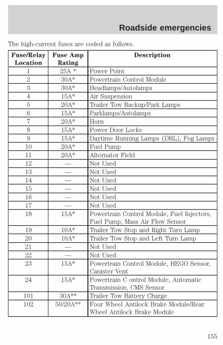
The high-current fuses are coded as follows.
Fuse/Relay
Location
Fuse Amp
Rating
Description
1 25A * Power Point2 30A* Powertrain Control Module3 30A* Headlamps/Autolamps4 15A* Air Suspension5 20A* Trailer Tow Backup/Park Lamps6 15A* Parklamps/Autolamps7 20A* Horn8 15A* Power Door Locks9 15A* Daytime Running Lamps (DRL), Fog Lamps
10 20A* Fuel Pump11 20A* Alternator Field12 — Not Used13 — Not Used14 — Not Used15 — Not Used16 — Not Used17 — Not Used18 15A* Powertrain Control Module, Fuel Injectors,
Fuel Pump, Mass Air Flow Sensor19 10A* Trailer Tow Stop and Right Turn Lamp20 10A* Trailer Tow Stop and Left Turn Lamp21 — Not Used22 — Not Used23 15A* Powertrain Control Module, HEGO Sensor,
Canister Vent24 15A* Powertrain C ontrol Module, Automatic
Transmission, CMS Sensor101 30A** Trailer Tow Battery Charge102 50/20A** Four Wheel Antilock Brake Module/Rear
Wheel Antilock Brake Module
Roadside emergencies
155
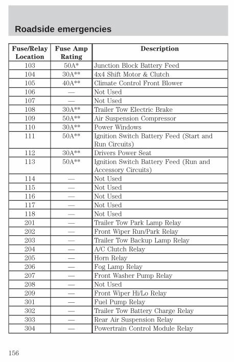
Fuse/Relay
Location
Fuse Amp
Rating
Description
103 50A* Junction Block Battery Feed104 30A** 4x4 Shift Motor & Clutch105 40A** Climate Control Front Blower106 — Not Used107 — Not Used108 30A** Trailer Tow Electric Brake109 50A** Air Suspension Compressor110 30A** Power Windows111 50A** Ignition Switch Battery Feed (Start and
Run Circuits)112 30A** Drivers Power Seat113 50A** Ignition Switch Battery Feed (Run and
Accessory Circuits)114 — Not Used115 — Not Used116 — Not Used117 — Not Used118 — Not Used201 — Trailer Tow Park Lamp Relay202 — Front Wiper Run/Park Relay203 — Trailer Tow Backup Lamp Relay204 — A/C Clutch Relay205 — Horn Relay206 — Fog Lamp Relay207 — Front Washer Pump Relay208 — Not Used209 — Front Wiper Hi/Lo Relay301 — Fuel Pump Relay302 — Trailer Tow Battery Charge Relay303 — Rear Air Suspension Relay304 — Powertrain Control Module Relay
Roadside emergencies
156
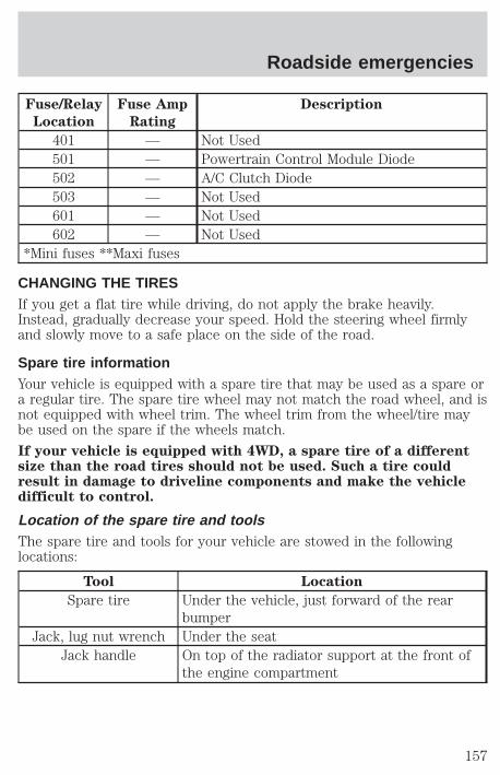
Fuse/Relay
Location
Fuse Amp
Rating
Description
401 — Not Used501 — Powertrain Control Module Diode502 — A/C Clutch Diode503 — Not Used601 — Not Used602 — Not Used
*Mini fuses **Maxi fuses
CHANGING THE TIRESIf you get a flat tire while driving, do not apply the brake heavily.Instead, gradually decrease your speed. Hold the steering wheel firmlyand slowly move to a safe place on the side of the road.
Spare tire informationYour vehicle is equipped with a spare tire that may be used as a spare ora regular tire. The spare tire wheel may not match the road wheel, and isnot equipped with wheel trim. The wheel trim from the wheel/tire maybe used on the spare if the wheels match.
If your vehicle is equipped with 4WD, a spare tire of a differentsize than the road tires should not be used. Such a tire couldresult in damage to driveline components and make the vehicledifficult to control.
Location of the spare tire and toolsThe spare tire and tools for your vehicle are stowed in the followinglocations:
Tool Location
Spare tire Under the vehicle, just forward of the rearbumper
Jack, lug nut wrench Under the seatJack handle On top of the radiator support at the front of
the engine compartment
Roadside emergencies
157
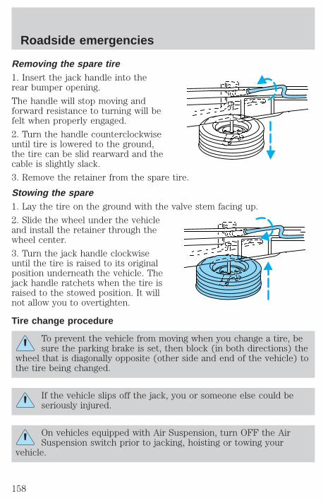
Removing the spare tire1. Insert the jack handle into therear bumper opening.
The handle will stop moving andforward resistance to turning will befelt when properly engaged.
2. Turn the handle counterclockwiseuntil tire is lowered to the ground,the tire can be slid rearward and thecable is slightly slack.
3. Remove the retainer from the spare tire.
Stowing the spare1. Lay the tire on the ground with the valve stem facing up.
2. Slide the wheel under the vehicleand install the retainer through thewheel center.
3. Turn the jack handle clockwiseuntil the tire is raised to its originalposition underneath the vehicle. Thejack handle ratchets when the tire israised to the stowed position. It willnot allow you to overtighten.
Tire change procedure
To prevent the vehicle from moving when you change a tire, besure the parking brake is set, then block (in both directions) the
wheel that is diagonally opposite (other side and end of the vehicle) tothe tire being changed.
If the vehicle slips off the jack, you or someone else could beseriously injured.
On vehicles equipped with Air Suspension, turn OFF the AirSuspension switch prior to jacking, hoisting or towing your
vehicle.
Roadside emergencies
158
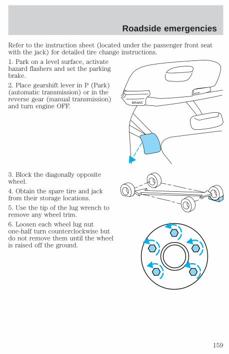
Refer to the instruction sheet (located under the passenger front seatwith the jack) for detailed tire change instructions.
1. Park on a level surface, activatehazard flashers and set the parkingbrake.
2. Place gearshift lever in P (Park)(automatic transmission) or in thereverse gear (manual transmission)and turn engine OFF.
3. Block the diagonally oppositewheel.
4. Obtain the spare tire and jackfrom their storage locations.
5. Use the tip of the lug wrench toremove any wheel trim.
6. Loosen each wheel lug nutone-half turn counterclockwise butdo not remove them until the wheelis raised off the ground.
BRAKE
HOOD
Roadside emergencies
159

7. Turn OFF the air suspensionswitch (if equipped).
8. Position the jack according to thefollowing guides and turn the jackhandle clockwise until the wheel iscompletely off the ground.
When one of the rearwheels is off the ground,
the transmission alone will notprevent the vehicle from movingor slipping off the jack, even if thetransmission is in P (Park) or inthe reverse gear (manualtransmission). To prevent thevehicle from moving when youchange the tire, be sure that theparking brake is set and thediagonally opposite wheel isblocked. If the vehicle slips off thejack, someone could be seriouslyinjured.
• Front (4x2)
AIR SUSPENSIONSWITCH
INTERRUPTEUR DELA SUSPENSIONPNEUMATIQUE
OFF
Roadside emergencies
160

• Front (4x4)
• Rear
To lessen the risk ofpersonal injury, do not put
any part of your body under thevehicle while changing a tire. Donot start the engine when yourvehicle is on the jack. The jack isonly meant for changing the tire.
• Never use the front or reardifferential as a jacking point.
9. Remove the lug nuts with the lug wrench.
10. Replace the flat tire with the spare tire, making sure the valve stemis facing outward. Reinstall the lug nuts until the wheel is snug againstthe hub. Do not fully tighten the lug nuts until the wheel has beenlowered.
11. Lower the wheel by turning the jack handle counterclockwise.
Roadside emergencies
161
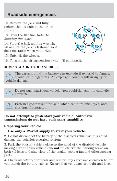
12. Remove the jack and fullytighten the lug nuts in the ordershown.
13. Stow the flat tire. Refer toStowing the spare .
14. Stow the jack and lug wrench.Make sure the jack is fastened so itdoes not rattle when you drive.
15. Unblock the wheels.
16. Turn on the air suspension switch (if equipped).
JUMP STARTING YOUR VEHICLE
The gases around the battery can explode if exposed to flames,sparks, or lit cigarettes. An explosion could result in injury or
vehicle damage.
Do not push start your vehicle. You could damage the catalyticconverter.
Batteries contain sulfuric acid which can burn skin, eyes, andclothing, if contacted.
Do not attempt to push start your vehicle. Automatictransmissions do not have push-start capability.
Preparing your vehicle1. Use only a 12–volt supply to start your vehicle.
2. Do not disconnect the battery of the disabled vehicle as this coulddamage the vehicle’s electrical system.
3. Park the booster vehicle close to the hood of the disabled vehiclemaking sure the two vehicles do not touch. Set the parking brake onboth vehicles and stay clear of the engine cooling fan and other movingparts.
4. Check all battery terminals and remove any excessive corrosion beforeyou attach the battery cables. Ensure that vent caps are tight and level.
1
43
5 2
Roadside emergencies
162
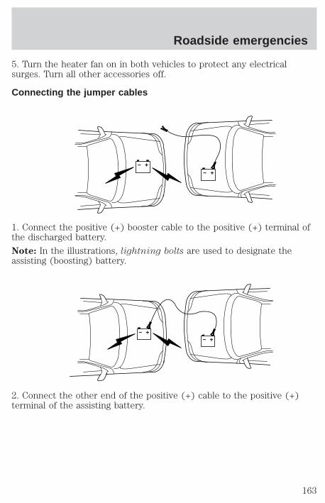
5. Turn the heater fan on in both vehicles to protect any electricalsurges. Turn all other accessories off.
Connecting the jumper cables
1. Connect the positive (+) booster cable to the positive (+) terminal ofthe discharged battery.
Note: In the illustrations, lightning bolts are used to designate theassisting (boosting) battery.
2. Connect the other end of the positive (+) cable to the positive (+)terminal of the assisting battery.
+–
+–
+–
+–
Roadside emergencies
163
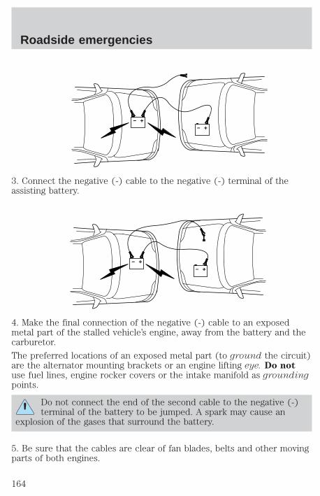
3. Connect the negative (-) cable to the negative (-) terminal of theassisting battery.
4. Make the final connection of the negative (-) cable to an exposedmetal part of the stalled vehicle’s engine, away from the battery and thecarburetor.
The preferred locations of an exposed metal part (to ground the circuit)are the alternator mounting brackets or an engine lifting eye. Do notuse fuel lines, engine rocker covers or the intake manifold as groundingpoints.
Do not connect the end of the second cable to the negative (-)terminal of the battery to be jumped. A spark may cause an
explosion of the gases that surround the battery.
5. Be sure that the cables are clear of fan blades, belts and other movingparts of both engines.
+–
+–
+–
+–
Roadside emergencies
164
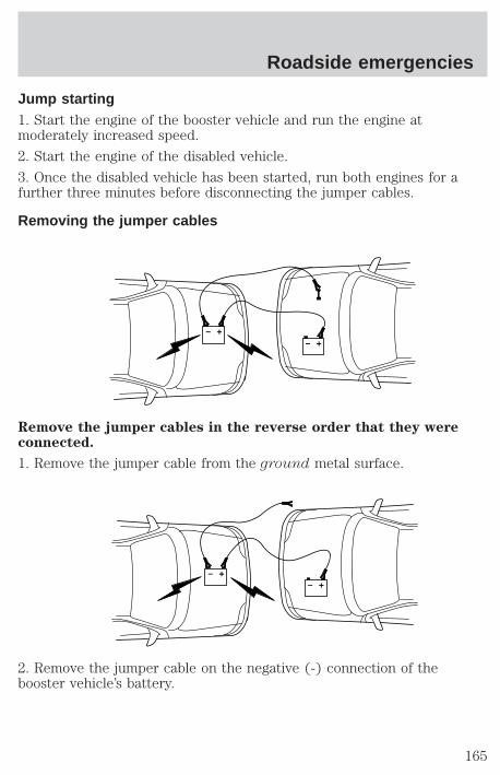
Jump starting1. Start the engine of the booster vehicle and run the engine atmoderately increased speed.
2. Start the engine of the disabled vehicle.
3. Once the disabled vehicle has been started, run both engines for afurther three minutes before disconnecting the jumper cables.
Removing the jumper cables
Remove the jumper cables in the reverse order that they wereconnected.
1. Remove the jumper cable from the ground metal surface.
2. Remove the jumper cable on the negative (-) connection of thebooster vehicle’s battery.
+–
+–
+–
+–
Roadside emergencies
165
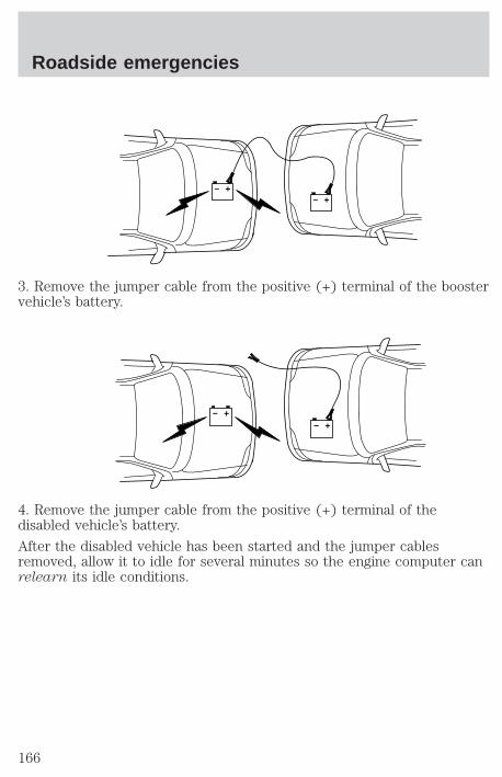
3. Remove the jumper cable from the positive (+) terminal of the boostervehicle’s battery.
4. Remove the jumper cable from the positive (+) terminal of thedisabled vehicle’s battery.
After the disabled vehicle has been started and the jumper cablesremoved, allow it to idle for several minutes so the engine computer canrelearn its idle conditions.
+–
+–
+–
+–
Roadside emergencies
166
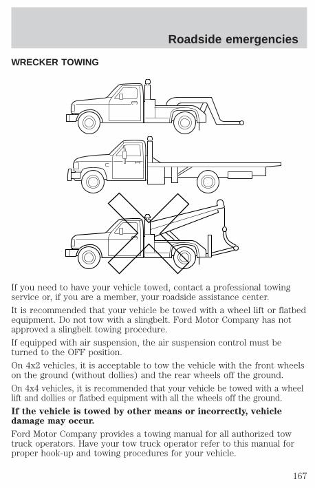
WRECKER TOWING
If you need to have your vehicle towed, contact a professional towingservice or, if you are a member, your roadside assistance center.
It is recommended that your vehicle be towed with a wheel lift or flatbedequipment. Do not tow with a slingbelt. Ford Motor Company has notapproved a slingbelt towing procedure.
If equipped with air suspension, the air suspension control must beturned to the OFF position.
On 4x2 vehicles, it is acceptable to tow the vehicle with the front wheelson the ground (without dollies) and the rear wheels off the ground.
On 4x4 vehicles, it is recommended that your vehicle be towed with a wheellift and dollies or flatbed equipment with all the wheels off the ground.
If the vehicle is towed by other means or incorrectly, vehicledamage may occur.
Ford Motor Company provides a towing manual for all authorized towtruck operators. Have your tow truck operator refer to this manual forproper hook-up and towing procedures for your vehicle.
Roadside emergencies
167
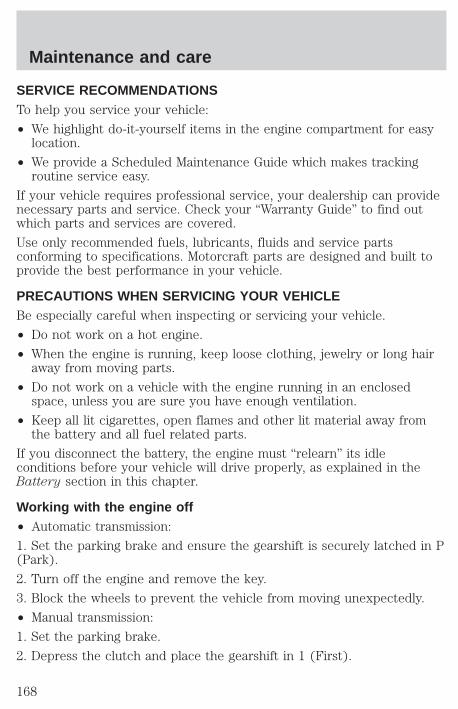
SERVICE RECOMMENDATIONSTo help you service your vehicle:
• We highlight do-it-yourself items in the engine compartment for easylocation.
• We provide a Scheduled Maintenance Guide which makes trackingroutine service easy.
If your vehicle requires professional service, your dealership can providenecessary parts and service. Check your “Warranty Guide” to find outwhich parts and services are covered.
Use only recommended fuels, lubricants, fluids and service partsconforming to specifications. Motorcraft parts are designed and built toprovide the best performance in your vehicle.
PRECAUTIONS WHEN SERVICING YOUR VEHICLEBe especially careful when inspecting or servicing your vehicle.
• Do not work on a hot engine.
• When the engine is running, keep loose clothing, jewelry or long hairaway from moving parts.
• Do not work on a vehicle with the engine running in an enclosedspace, unless you are sure you have enough ventilation.
• Keep all lit cigarettes, open flames and other lit material away fromthe battery and all fuel related parts.
If you disconnect the battery, the engine must “relearn” its idleconditions before your vehicle will drive properly, as explained in theBattery section in this chapter.
Working with the engine off• Automatic transmission:
1. Set the parking brake and ensure the gearshift is securely latched in P(Park).
2. Turn off the engine and remove the key.
3. Block the wheels to prevent the vehicle from moving unexpectedly.
• Manual transmission:
1. Set the parking brake.
2. Depress the clutch and place the gearshift in 1 (First).
Maintenance and care
168

3. Turn off the engine and remove the key.
4. Block the wheels to prevent the vehicle from moving unexpectedly.
Working with the engine on• Automatic transmission:
1. Set the parking brake and ensure the gearshift is securely latched in P(Park).
2. Block the wheels to prevent the vehicle from moving unexpectedly.
Do not start your engine with the air cleaner removed and donot remove it while the engine is running.
• Manual transmission:
1. Set the parking brake, depress the clutch and place the gearshift in N(Neutral).
2. Block the wheels to prevent the vehicle from moving unexpectedly.
Do not start your engine with the air cleaner removed and donot remove it while the engine is running.
OPENING THE HOOD1. Inside the vehicle, pull the hoodrelease handle located under thebottom of the instrument panel.
2. Go to the front of the vehicle andrelease the auxiliary latch that islocated under the front center ofthe hood.
3. Lift the hood until the liftcylinders hold it open.
BRAKE
HOOD
Maintenance and care
169
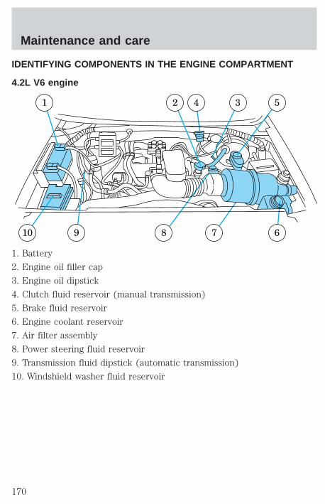
IDENTIFYING COMPONENTS IN THE ENGINE COMPARTMENT
4.2L V6 engine
1. Battery
2. Engine oil filler cap
3. Engine oil dipstick
4. Clutch fluid reservoir (manual transmission)
5. Brake fluid reservoir
6. Engine coolant reservoir
7. Air filter assembly
8. Power steering fluid reservoir
9. Transmission fluid dipstick (automatic transmission)
10. Windshield washer fluid reservoir
67
1 2 4 5
8910
3
Maintenance and care
170
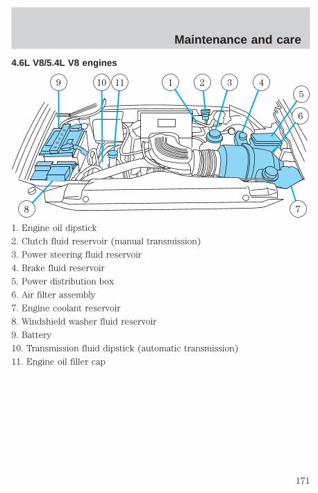
4.6L V8/5.4L V8 engines
1. Engine oil dipstick
2. Clutch fluid reservoir (manual transmission)
3. Power steering fluid reservoir
4. Brake fluid reservoir
5. Power distribution box
6. Air filter assembly
7. Engine coolant reservoir
8. Windshield washer fluid reservoir
9. Battery
10. Transmission fluid dipstick (automatic transmission)
11. Engine oil filler cap
8 7
9 10 11 1 32 4
6
5
Maintenance and care
171

ENGINE OIL
Checking the engine oilRefer to the Scheduled Maintenance Guide for the appropriate intervalsfor checking the engine oil.
1. Make sure the vehicle is on level ground.
2. Turn the engine off and wait a few minutes for the oil to drain into theoil pan.
3. Set the parking brake and ensure the gearshift is securely latched in P(Park) (automatic transmission) or 1 (First) (manual transmission).
4. Open the hood. Protect yourself from engine heat.
5. Locate and carefully remove theengine oil level indicator (dipstick).
6. Wipe the indicator clean. Insert the indicator fully, then remove itagain.
• If the oil level is between the MIN and MAX marks, the oil level isacceptable. DO NOT ADD OIL.
MAXMIN
Maintenance and care
172
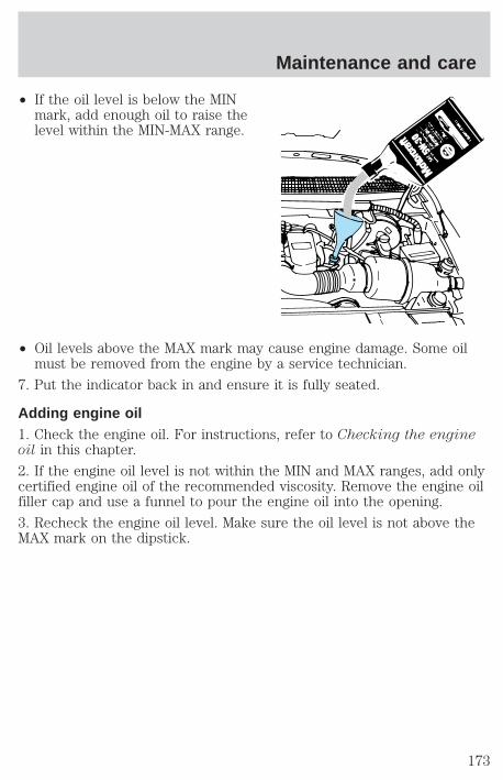
• If the oil level is below the MINmark, add enough oil to raise thelevel within the MIN-MAX range.
• Oil levels above the MAX mark may cause engine damage. Some oilmust be removed from the engine by a service technician.
7. Put the indicator back in and ensure it is fully seated.
Adding engine oil1. Check the engine oil. For instructions, refer to Checking the engineoil in this chapter.
2. If the engine oil level is not within the MIN and MAX ranges, add onlycertified engine oil of the recommended viscosity. Remove the engine oilfiller cap and use a funnel to pour the engine oil into the opening.
3. Recheck the engine oil level. Make sure the oil level is not above theMAX mark on the dipstick.
Maintenance and care
173
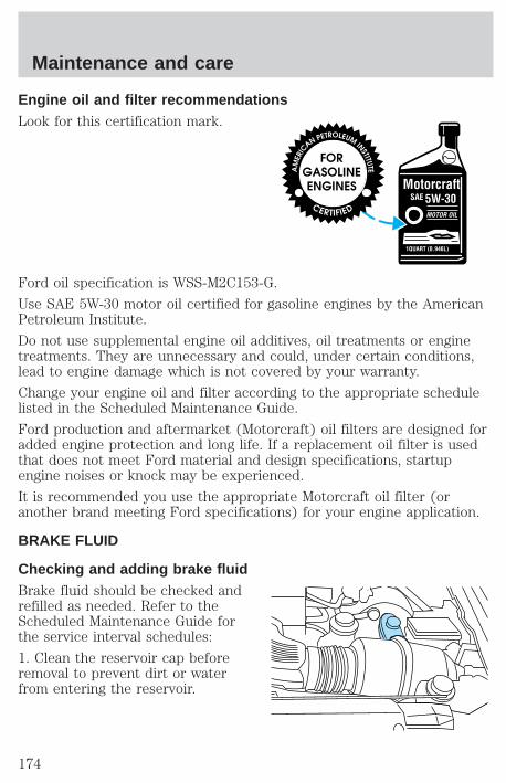
Engine oil and filter recommendationsLook for this certification mark.
Ford oil specification is WSS-M2C153-G.
Use SAE 5W-30 motor oil certified for gasoline engines by the AmericanPetroleum Institute.
Do not use supplemental engine oil additives, oil treatments or enginetreatments. They are unnecessary and could, under certain conditions,lead to engine damage which is not covered by your warranty.
Change your engine oil and filter according to the appropriate schedulelisted in the Scheduled Maintenance Guide.
Ford production and aftermarket (Motorcraft) oil filters are designed foradded engine protection and long life. If a replacement oil filter is usedthat does not meet Ford material and design specifications, startupengine noises or knock may be experienced.
It is recommended you use the appropriate Motorcraft oil filter (oranother brand meeting Ford specifications) for your engine application.
BRAKE FLUID
Checking and adding brake fluidBrake fluid should be checked andrefilled as needed. Refer to theScheduled Maintenance Guide forthe service interval schedules:
1. Clean the reservoir cap beforeremoval to prevent dirt or waterfrom entering the reservoir.
Maintenance and care
174
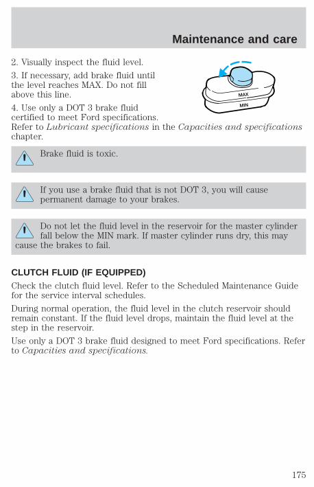
2. Visually inspect the fluid level.
3. If necessary, add brake fluid untilthe level reaches MAX. Do not fillabove this line.
4. Use only a DOT 3 brake fluidcertified to meet Ford specifications.Refer to Lubricant specifications in the Capacities and specificationschapter.
Brake fluid is toxic.
If you use a brake fluid that is not DOT 3, you will causepermanent damage to your brakes.
Do not let the fluid level in the reservoir for the master cylinderfall below the MIN mark. If master cylinder runs dry, this may
cause the brakes to fail.
CLUTCH FLUID (IF EQUIPPED)Check the clutch fluid level. Refer to the Scheduled Maintenance Guidefor the service interval schedules.
During normal operation, the fluid level in the clutch reservoir shouldremain constant. If the fluid level drops, maintain the fluid level at thestep in the reservoir.
Use only a DOT 3 brake fluid designed to meet Ford specifications. Referto Capacities and specifications.
MAX
MIN
Maintenance and care
175
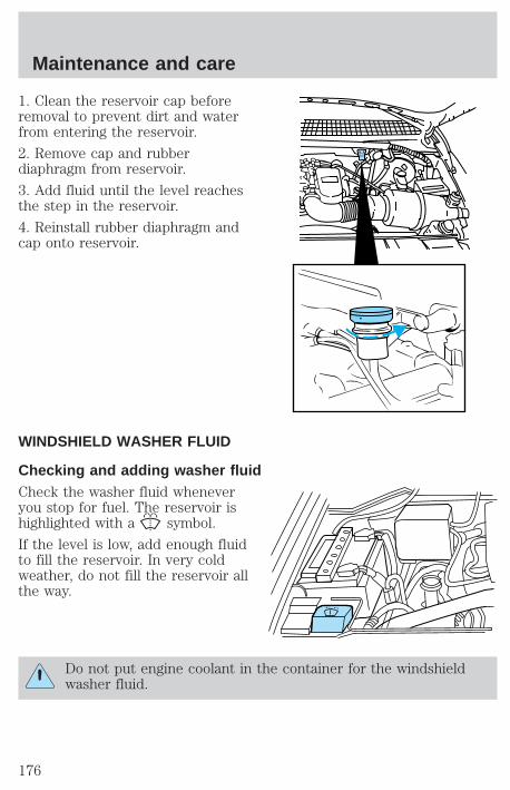
1. Clean the reservoir cap beforeremoval to prevent dirt and waterfrom entering the reservoir.
2. Remove cap and rubberdiaphragm from reservoir.
3. Add fluid until the level reachesthe step in the reservoir.
4. Reinstall rubber diaphragm andcap onto reservoir.
WINDSHIELD WASHER FLUID
Checking and adding washer fluidCheck the washer fluid wheneveryou stop for fuel. The reservoir ishighlighted with a symbol.
If the level is low, add enough fluidto fill the reservoir. In very coldweather, do not fill the reservoir allthe way.
Do not put engine coolant in the container for the windshieldwasher fluid.
Maintenance and care
176
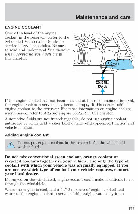
ENGINE COOLANTCheck the level of the enginecoolant in the reservoir. Refer to theScheduled Maintenance Guide forservice interval schedules. Be sureto read and understand Precautionswhen servicing your vehicle inthis chapter.
If the engine coolant has not been checked at the recommended interval,the engine coolant reservoir may become empty. If this occurs, addengine coolant to the reservoir. For more information on engine coolantmaintenance, refer to Adding engine coolant in this chapter.
Automotive fluids are not interchangeable; do not use engine coolant,antifreeze or windshield washer fluid outside of its specified function andvehicle location.
Adding engine coolant
Do not put engine coolant in the reservoir for the windshieldwasher fluid.
Do not mix conventional green coolant, orange coolant orrecycled coolants together in your vehicle. Use only the type ofcoolant with which your vehicle was originally equipped. If youare unsure which type of coolant your vehicle requires, contactyour local dealer.
If sprayed on the windshield, engine coolant could make it difficult to seethrough the windshield.
When the engine is cool, add a 50/50 mixture of engine coolant andwater to the engine coolant reservoir. Add straight water only in an
COLD FILLRANGE
Maintenance and care
177
emergency, but you should replace it with a 50/50 mixture of coolant anddistilled water as soon as possible.
Check the coolant level in the coolant reservoir the next few times youdrive the vehicle. If necessary, add enough of a 50/50 mixture of coolantand water to bring the liquid level into the cold fill range on thereservoir.
Never remove the coolant reservoir cap while the engine isrunning or hot.
If you must remove the coolant reservoir cap, follow these steps to avoidpersonal injury:
1. Before you remove the cap, turn the engine off and let it cool.
2. When the engine is cool, wrap a thick cloth around the cap. Slowlyturn cap counterclockwise until pressure begins to release.
3. Step back while the pressure releases.
4. When you are sure that all the pressure has been released, use thecloth to turn it counterclockwise and remove the cap.
Change your engine coolant according to the appropriate schedule listedin the Scheduled Maintenance Guide.
Use Ford Premium Engine Coolant E2FZ-19549–AA (in Oregon,F5FZ-19549–CC, in Canada, Motorcraft CXC-10) or an equivalentpremium engine coolant that meets Ford specification ESE-M97B44–A.
DO NOT USE Ford Extended Life Engine CoolantF6AZ-19544–AA, meeting Ford specification WSS-M97B44–D(orange in color). Do not add recycled coolant to your vehicle.
Do not use alcohol or methanol antifreeze or any engine coolants mixedwith alcohol or methanol antifreeze. Do not use supplemental coolantadditives in your vehicle. These additives may harm your engine coolingsystem. The use of an improper coolant may void your warranty of yourvehicle’s engine cooling system.
Recycled engine coolantFord Motor Company recommends that Ford and Lincoln-Mercurydealers use recycled engine coolant produced by Ford-approvedprocesses.
Maintenance and care
178
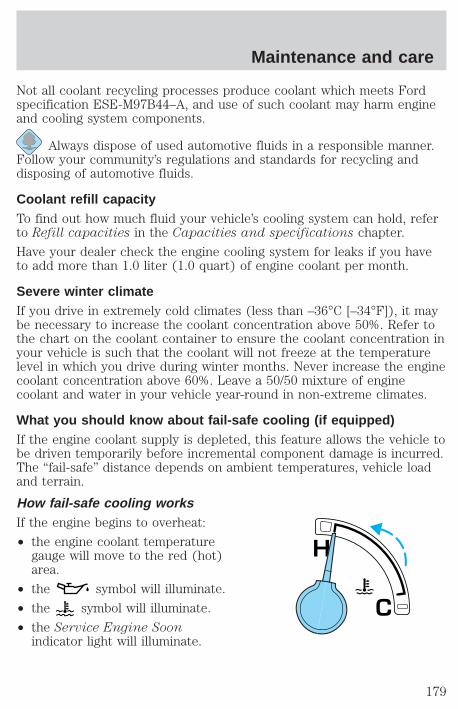
Not all coolant recycling processes produce coolant which meets Fordspecification ESE-M97B44–A, and use of such coolant may harm engineand cooling system components.
Always dispose of used automotive fluids in a responsible manner.Follow your community’s regulations and standards for recycling anddisposing of automotive fluids.
Coolant refill capacityTo find out how much fluid your vehicle’s cooling system can hold, referto Refill capacities in the Capacities and specifications chapter.
Have your dealer check the engine cooling system for leaks if you haveto add more than 1.0 liter (1.0 quart) of engine coolant per month.
Severe winter climateIf you drive in extremely cold climates (less than –36°C [–34°F]), it maybe necessary to increase the coolant concentration above 50%. Refer tothe chart on the coolant container to ensure the coolant concentration inyour vehicle is such that the coolant will not freeze at the temperaturelevel in which you drive during winter months. Never increase the enginecoolant concentration above 60%. Leave a 50/50 mixture of enginecoolant and water in your vehicle year-round in non-extreme climates.
What you should know about fail-safe cooling (if equipped)If the engine coolant supply is depleted, this feature allows the vehicle tobe driven temporarily before incremental component damage is incurred.The “fail-safe” distance depends on ambient temperatures, vehicle loadand terrain.
How fail-safe cooling worksIf the engine begins to overheat:
• the engine coolant temperaturegauge will move to the red (hot)area.
• the symbol will illuminate.
• the symbol will illuminate.
• the Service Engine Soonindicator light will illuminate.
C
H
Maintenance and care
179

If the engine reaches a preset over-temperature condition, the enginewill automatically switch to alternating cylinder operation. Each disabledcylinder acts as an air pump and cools the engine.
When this occurs the vehicle will still operate, however:
• the engine power will be limited.
• the air conditioning system will be disabled.
Continued operation will increase the engine temperature:
• the engine will completely shut down.
• steering and braking effort will increase.
Once the engine temperature cools, the engine can be re-started. Takeyour vehicle to a service facility as soon as possible to minimize enginedamage.
When fail-safe mode is activatedYou have limited engine power when in the fail-safe mode, so drive thevehicle with caution. The vehicle will not be able to maintain high speedoperation and the engine will run rough. Remember that the engine iscapable of completely shutting down automatically to prevent enginedamage, therefore:
1. Pull off the road as soon as safely possible and turn off the engine.
2. Arrange for the vehicle to be taken to a service facility.
3. If this is not possible, wait a short period for the engine to cool.
4. Check the coolant level and replenish if low.
Never remove the coolant reservoir cap while the engine isrunning or hot.
5. Re start the engine and take your vehicle to a service facility.
Driving the vehicle without repairing the engine problemincreases the chance of engine damage. Take your vehicle to a
service facility as soon as possible.
Maintenance and care
180
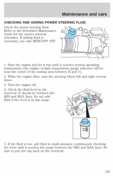
CHECKING AND ADDING POWER STEERING FLUIDCheck the power steering fluid.Refer to the Scheduled MaintenanceGuide for the service intervalschedules. If adding fluid isnecessary, use only MERCONt ATF.
1. Start the engine and let it run until it reaches normal operatingtemperature (the engine coolant temperature gauge indicator will benear the center of the normal area between H and C).
2. While the engine idles, turn the steering wheel left and right severaltimes.
3. Turn the engine off.
4. Check the fluid level in thereservoir. It should be between theMIN and MAX lines. Do not addfluid if the level is in this range.
5. If the fluid is low, add fluid in small amounts, continuously checkingthe level until it reaches the range between the MIN and MAX lines. Besure to put the cap back on the reservoir.
MAXMIN
MAXMIN
Maintenance and care
181
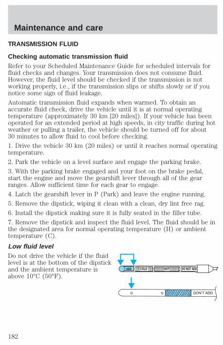
TRANSMISSION FLUID
Checking automatic transmission fluidRefer to your Scheduled Maintenance Guide for scheduled intervals forfluid checks and changes. Your transmission does not consume fluid.However, the fluid level should be checked if the transmission is notworking properly, i.e., if the transmission slips or shifts slowly or if younotice some sign of fluid leakage.
Automatic transmission fluid expands when warmed. To obtain anaccurate fluid check, drive the vehicle until it is at normal operatingtemperature (approximately 30 km [20 miles]). If your vehicle has beenoperated for an extended period at high speeds, in city traffic during hotweather or pulling a trailer, the vehicle should be turned off for about30 minutes to allow fluid to cool before checking.
1. Drive the vehicle 30 km (20 miles) or until it reaches normal operatingtemperature.
2. Park the vehicle on a level surface and engage the parking brake.
3. With the parking brake engaged and your foot on the brake pedal,start the engine and move the gearshift lever through all of the gearranges. Allow sufficient time for each gear to engage.
4. Latch the gearshift lever in P (Park) and leave the engine running.
5. Remove the dipstick, wiping it clean with a clean, dry lint free rag.
6. Install the dipstick making sure it is fully seated in the filler tube.
7. Remove the dipstick and inspect the fluid level. The fluid should be inthe designated area for normal operating temperature (H) or ambienttemperature (C).
Low fluid levelDo not drive the vehicle if the fluidlevel is at the bottom of the dipstickand the ambient temperature isabove 10°C (50°F).
ADD COLD HOT DO NOT ADD
DON’T ADD
Maintenance and care
182
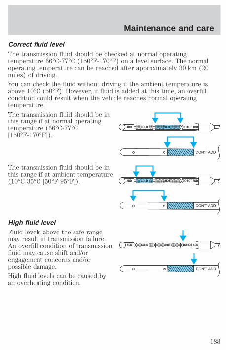
Correct fluid levelThe transmission fluid should be checked at normal operatingtemperature 66°C-77°C (150°F-170°F) on a level surface. The normaloperating temperature can be reached after approximately 30 km (20miles) of driving.
You can check the fluid without driving if the ambient temperature isabove 10°C (50°F). However, if fluid is added at this time, an overfillcondition could result when the vehicle reaches normal operatingtemperature.
The transmission fluid should be inthis range if at normal operatingtemperature (66°C-77°C[150°F-170°F]).
The transmission fluid should be inthis range if at ambient temperature(10°C-35°C [50°F-95°F]).
High fluid levelFluid levels above the safe rangemay result in transmission failure.An overfill condition of transmissionfluid may cause shift and/orengagement concerns and/orpossible damage.
High fluid levels can be caused byan overheating condition.
ADD COLD HOT DO NOT ADD
DON’T ADD
ADD COLD HOT DO NOT ADD
DON’T ADD
ADD COLD HOT DO NOT ADD
DON’T ADD
Maintenance and care
183

Adjusting automatic transmission fluid levelsBefore adding any fluid, make sure the correct type is used. The type offluid used is normally indicated on the dipstick and/or dipstick handleand also in the Lubricant specifications section in the Capacities andspecifications chapter.
Use of a non-approved automatic transmission fluid may causeinternal transmission component damage.
If necessary, add fluid in 250 mL (1/2 pint) increments through the fillertube until the level is correct.
If an overfill occurs, excess fluidshould be removed by a qualifiedtechnician.
An overfill condition oftransmission fluid may causeshift and/or engagementconcerns and/or possibledamage.
Checking and adding manual transmission fluid1. Clean the filler plug.
2. Remove the filler plug andinspect the fluid level.
ADD COLD HOT DO NOT ADD
DON’T ADD
Maintenance and care
184

3. Fluid level should be at bottom ofthe opening.
4. Add enough fluid through thefiller opening so that the fluid levelis at the bottom of the opening.
5. Install and tighten the fill plugsecurely.
Use only fluid that meets Ford specifications. Refer to the Capacitiesand specifications chapter.
Checking and adding transfer case fluid1. Clean the filler plug.
2. Remove the filler plug andinspect the fluid level.
Maintenance and care
185
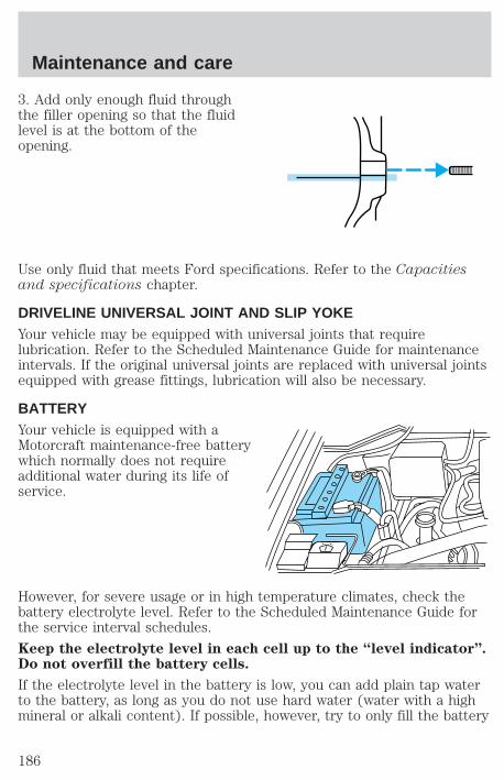
3. Add only enough fluid throughthe filler opening so that the fluidlevel is at the bottom of theopening.
Use only fluid that meets Ford specifications. Refer to the Capacitiesand specifications chapter.
DRIVELINE UNIVERSAL JOINT AND SLIP YOKEYour vehicle may be equipped with universal joints that requirelubrication. Refer to the Scheduled Maintenance Guide for maintenanceintervals. If the original universal joints are replaced with universal jointsequipped with grease fittings, lubrication will also be necessary.
BATTERYYour vehicle is equipped with aMotorcraft maintenance-free batterywhich normally does not requireadditional water during its life ofservice.
However, for severe usage or in high temperature climates, check thebattery electrolyte level. Refer to the Scheduled Maintenance Guide forthe service interval schedules.
Keep the electrolyte level in each cell up to the “level indicator”.Do not overfill the battery cells.
If the electrolyte level in the battery is low, you can add plain tap waterto the battery, as long as you do not use hard water (water with a highmineral or alkali content). If possible, however, try to only fill the battery
Maintenance and care
186
cells with distilled water. If the battery needs water often, have thecharging system checked.
If your battery has a cover/shield, make sure it is reinstalledafter the battery has been cleaned or replaced.
For longer, trouble-free operation, keep the top of the battery clean anddry. Also, make certain the battery cables are always tightly fastened tothe battery terminals.
If you see any corrosion on the battery or terminals, remove the cablesfrom the terminals and clean with a wire brush. You can neutralize theacid with a solution of baking soda and water.
Batteries normally produce explosive gases which can causepersonal injury. Therefore, do not allow flames, sparks or lighted
substances to come near the battery. When working near the battery,always shield your face and protect your eyes. Always provide properventilation.
When lifting a plastic-cased battery, excessive pressure on theend walls could cause acid to flow through the vent caps,
resulting in personal injury and/or damage to the vehicle or battery.Lift the battery with a battery carrier or with your hands on oppositecorners.
Keep batteries out of reach of children. Batteries contain sulfuricacid. Avoid contact with skin, eyes or clothing. Shield your eyes
when working near the battery to protect against possible splashing ofacid solution. In case of acid contact with skin or eyes, flushimmediately with water for a minimum of 15 minutes and get promptmedical attention. If acid is swallowed, call a physician immediately.
Because your vehicle’s engine is also electronically controlled by acomputer, some control conditions are maintained by power from thebattery. When the battery is disconnected or a new battery is installed,the engine must relearn its idle and fuel trim strategy for optimumdriveability and performance. To begin this process:
1. Set your parking brake.
Maintenance and care
187
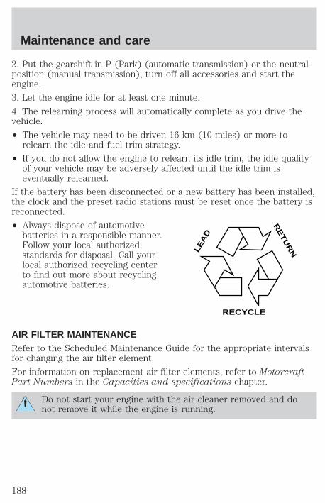
2. Put the gearshift in P (Park) (automatic transmission) or the neutralposition (manual transmission), turn off all accessories and start theengine.
3. Let the engine idle for at least one minute.
4. The relearning process will automatically complete as you drive thevehicle.
• The vehicle may need to be driven 16 km (10 miles) or more torelearn the idle and fuel trim strategy.
• If you do not allow the engine to relearn its idle trim, the idle qualityof your vehicle may be adversely affected until the idle trim iseventually relearned.
If the battery has been disconnected or a new battery has been installed,the clock and the preset radio stations must be reset once the battery isreconnected.
• Always dispose of automotivebatteries in a responsible manner.Follow your local authorizedstandards for disposal. Call yourlocal authorized recycling centerto find out more about recyclingautomotive batteries.
AIR FILTER MAINTENANCERefer to the Scheduled Maintenance Guide for the appropriate intervalsfor changing the air filter element.
For information on replacement air filter elements, refer to MotorcraftPart Numbers in the Capacities and specifications chapter.
Do not start your engine with the air cleaner removed and donot remove it while the engine is running.
LE
AD
RE
TU
RN
RECYCLE
Maintenance and care
188
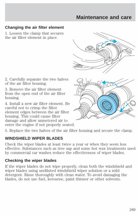
Changing the air filter element1. Loosen the clamp that securesthe air filter element in place.
2. Carefully separate the two halvesof the air filter housing.
3. Remove the air filter elementfrom the open end of the air filterhousing.
4. Install a new air filter element. Becareful not to crimp the filterelement edges between the air filterhousing. This could cause filterdamage and allow unmetered air toenter the engine if not properly seated.
5. Replace the two halves of the air filter housing and secure the clamp.
WINDSHIELD WIPER BLADESCheck the wiper blades at least twice a year or when they seem lesseffective. Substances such as tree sap and some hot wax treatments usedby commercial car washes reduce the effectiveness of wiper blades.
Checking the wiper bladesIf the wiper blades do not wipe properly, clean both the windshield andwiper blades using undiluted windshield wiper solution or a milddetergent. Rinse thoroughly with clean water. To avoid damaging theblades, do not use fuel, kerosene, paint thinner or other solvents.
Maintenance and care
189

Changing the wiper bladesTo replace the wiper blades:
1. Pull the wiper arm away from thewindshield and lock into the serviceposition.
2. Turn the blade at an angle fromthe wiper arm. Push the lock pinmanually to release the blade andpull the wiper blade down towardthe windshield to remove it from thearm.
3. Attach the new wiper to thewiper arm and press it into placeuntil a click is heard.
INFORMATION ABOUT TIRE QUALITY GRADESNew vehicles are fitted with tiresthat have their Tire Quality Grade(described below) molded into thetire’s sidewall. These Tire QualityGrades are determined by standardsthat the United States Departmentof Transportation has set.
Tire Quality Grades apply to newpneumatic tires for use onpassenger cars. They do not applyto deep tread, winter-type snowtires, space-saver or temporary use spare tires, tires with nominal rimdiameters of 10 to 12 inches or limited production tires as defined inTitle 49 Code of Federal Regulations Part 575.104(c)(2).
U.S. Department of Transportation-Tire quality grades: The U.S.Department of Transportation requires Ford to give you the followinginformation about tire grades exactly as the government has written it.
Maintenance and care
190
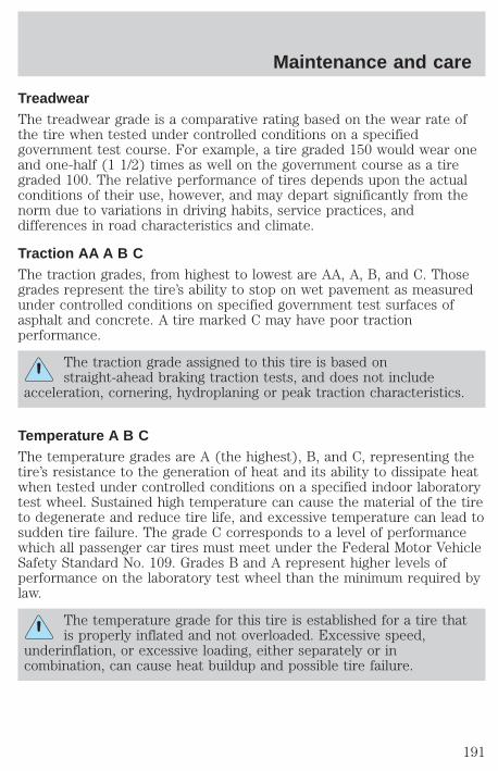
TreadwearThe treadwear grade is a comparative rating based on the wear rate ofthe tire when tested under controlled conditions on a specifiedgovernment test course. For example, a tire graded 150 would wear oneand one-half (1 1/2) times as well on the government course as a tiregraded 100. The relative performance of tires depends upon the actualconditions of their use, however, and may depart significantly from thenorm due to variations in driving habits, service practices, anddifferences in road characteristics and climate.
Traction AA A B CThe traction grades, from highest to lowest are AA, A, B, and C. Thosegrades represent the tire’s ability to stop on wet pavement as measuredunder controlled conditions on specified government test surfaces ofasphalt and concrete. A tire marked C may have poor tractionperformance.
The traction grade assigned to this tire is based onstraight-ahead braking traction tests, and does not include
acceleration, cornering, hydroplaning or peak traction characteristics.
Temperature A B CThe temperature grades are A (the highest), B, and C, representing thetire’s resistance to the generation of heat and its ability to dissipate heatwhen tested under controlled conditions on a specified indoor laboratorytest wheel. Sustained high temperature can cause the material of the tireto degenerate and reduce tire life, and excessive temperature can lead tosudden tire failure. The grade C corresponds to a level of performancewhich all passenger car tires must meet under the Federal Motor VehicleSafety Standard No. 109. Grades B and A represent higher levels ofperformance on the laboratory test wheel than the minimum required bylaw.
The temperature grade for this tire is established for a tire thatis properly inflated and not overloaded. Excessive speed,
underinflation, or excessive loading, either separately or incombination, can cause heat buildup and possible tire failure.
Maintenance and care
191
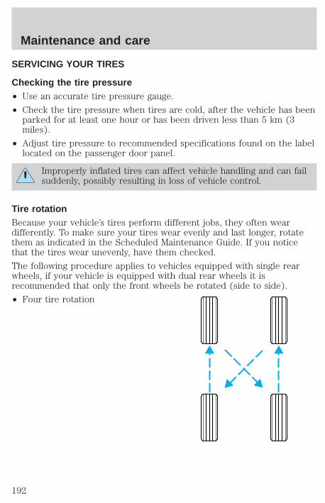
SERVICING YOUR TIRES
Checking the tire pressure• Use an accurate tire pressure gauge.
• Check the tire pressure when tires are cold, after the vehicle has beenparked for at least one hour or has been driven less than 5 km (3miles).
• Adjust tire pressure to recommended specifications found on the labellocated on the passenger door panel.
Improperly inflated tires can affect vehicle handling and can failsuddenly, possibly resulting in loss of vehicle control.
Tire rotationBecause your vehicle’s tires perform different jobs, they often weardifferently. To make sure your tires wear evenly and last longer, rotatethem as indicated in the Scheduled Maintenance Guide. If you noticethat the tires wear unevenly, have them checked.
The following procedure applies to vehicles equipped with single rearwheels, if your vehicle is equipped with dual rear wheels it isrecommended that only the front wheels be rotated (side to side).
• Four tire rotation
Maintenance and care
192
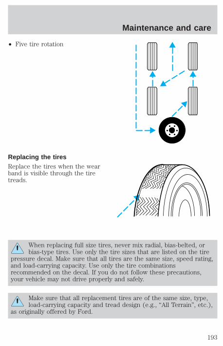
• Five tire rotation
Replacing the tiresReplace the tires when the wearband is visible through the tiretreads.
When replacing full size tires, never mix radial, bias-belted, orbias-type tires. Use only the tire sizes that are listed on the tire
pressure decal. Make sure that all tires are the same size, speed rating,and load-carrying capacity. Use only the tire combinationsrecommended on the decal. If you do not follow these precautions,your vehicle may not drive properly and safely.
Make sure that all replacement tires are of the same size, type,load-carrying capacity and tread design (e.g., “All Terrain”, etc.),
as originally offered by Ford.
Maintenance and care
193
Do not replace your tires with “high performance” tires or largersize tires.
Failure to follow these precautions may adversely affect thehandling of the vehicle and make it easier for the driver to lose
control and roll over.
Tires that are larger or smaller than your vehicle’s original tires may alsoaffect the accuracy of your speedometer.
SNOW TIRES AND CHAINS
Snow tires must be the same size and grade as the tires youcurrently have on your vehicle.
The tires on your vehicle have all weather treads to provide traction inrain and snow. However, in some climates, you may need to use snowtires and chains. If you need to use chains, it is recommended that steelwheels (of the same size and specifications) be used as chains may chipaluminum wheels.
Follow these guidelines when using snow tires and chains:
• Use only SAE Class S chains.
• Install chains securely, verifying that the chains do not touch anywiring, brake lines or fuel lines.
• Drive cautiously. If you hear the chains rub or bang against yourvehicle, stop and re-tighten the chains. If this does not work, removethe chains to prevent damage to your vehicle.
• If possible, avoid fully loading your vehicle.
• Remove the tire chains when they are no longer needed. Do not usetire chains on dry roads.
• The suspension insulation and bumpers will help prevent vehicledamage. Do not remove these components from your vehicle whenusing snow tires and chains.
Maintenance and care
194
WHAT YOU SHOULD KNOW ABOUT AUTOMOTIVE FUELS
Important safety precautions
Do not overfill the fuel tank. The pressure in an overfilled tankmay cause leakage and lead to fuel spray and fire.
If you do not use the proper fuel cap, the pressure in the fueltank can damage the fuel system or cause it to work improperly
in a collision.
The fuel system may be under pressure. If the fuel cap is ventingvapor or if you hear a hissing sound, wait until it stops before
completely removing the cap.
Automotive fuels can cause serious injury or death if misused ormishandled.
Observe the following guidelines when handling automotive fuel:
• Extinguish all smoking materialsand any open flames beforefueling your vehicle.
• Always turn off the vehicle beforefueling.
• Automotive fuels can be harmfulor fatal if swallowed. Fuel such asgasoline is highly toxic and ifswallowed can cause death orpermanent injury. If fuel isswallowed, call a physician immediately, even if no symptoms areimmediately apparent. The toxic effects of fuel may not be visible forhours.
• Avoid inhaling fuel vapors. Inhaling too much fuel vapor of any kindcan lead to eye and respiratory tract irritation. In severe cases,excessive or prolonged breathing of fuel vapor can cause seriousillness and permanent injury.
Maintenance and care
195

• Avoid getting fuel liquid in your eyes. If fuel is splashed in the eyes,remove contact lenses (if worn), flush with water for 15 minutes andseek medical attention. Failure to seek proper medical attention couldlead to permanent injury.
• Fuels can also be harmful if absorbed through the skin. If fuel issplashed on the skin and/or clothing, promptly remove contaminatedclothing and wash skin thoroughly with soap and water. Repeated orprolonged skin contact with fuel liquid or vapor causes skin irritation.
• Be particularly careful if you are taking “Antabuse” or other forms ofdisulfiram for the treatment of alcoholism. Breathing gasoline vapors,or skin contact could cause an adverse reaction. In sensitiveindividuals, serious personal injury or sickness may result. If fuel issplashed on the skin, promptly wash skin thoroughly with soap andwater. Consult a physician immediately if you experience an adversereaction.
Choosing the right fuelUse only UNLEADED FUEL. The use of leaded fuel is prohibited by lawand could damage your vehicle.
Do not use gasolines containing methanol. It can damage critical fuelsystems components.
Vehicles certified to meet California emission standards (indicated on theunderhood Vehicle Emissions Control Information label) are designed tooperate on California cleaner-burning, low-sulfur gasolines. If you have aCalifornia-certified vehicle and California cleaner-burning gasoline is notavailable when you refuel, your engine should perform adequately.However, the performance of the emission control devices and systemsmay be adversely affected. In New York and Massachusetts, which haveadopted California’s emission standards without requiring the sale ofCalifornia cleaner-burning gasoline, repairs to correct the effects of usingnon-California fuel may not be covered by the emissions warranty.
Your vehicle was not designed to use fuel or fuel additives with metalliccompounds, including manganese-based compounds containing (MMT).
Repairs to correct the effects of using a fuel for which your vehicle wasnot designed may not be covered by your warranty.
Maintenance and care
196
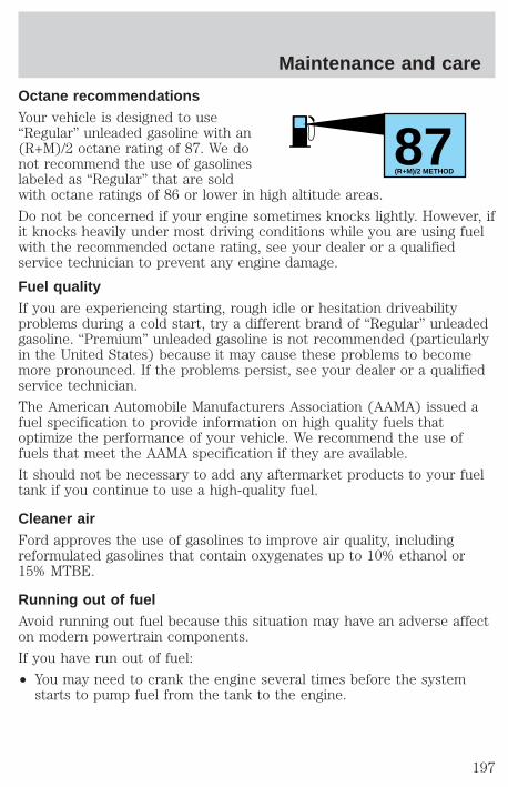
Octane recommendationsYour vehicle is designed to use“Regular” unleaded gasoline with an(R+M)/2 octane rating of 87. We donot recommend the use of gasolineslabeled as “Regular” that are soldwith octane ratings of 86 or lower in high altitude areas.
Do not be concerned if your engine sometimes knocks lightly. However, ifit knocks heavily under most driving conditions while you are using fuelwith the recommended octane rating, see your dealer or a qualifiedservice technician to prevent any engine damage.
Fuel qualityIf you are experiencing starting, rough idle or hesitation driveabilityproblems during a cold start, try a different brand of “Regular” unleadedgasoline. “Premium” unleaded gasoline is not recommended (particularlyin the United States) because it may cause these problems to becomemore pronounced. If the problems persist, see your dealer or a qualifiedservice technician.
The American Automobile Manufacturers Association (AAMA) issued afuel specification to provide information on high quality fuels thatoptimize the performance of your vehicle. We recommend the use offuels that meet the AAMA specification if they are available.
It should not be necessary to add any aftermarket products to your fueltank if you continue to use a high-quality fuel.
Cleaner airFord approves the use of gasolines to improve air quality, includingreformulated gasolines that contain oxygenates up to 10% ethanol or15% MTBE.
Running out of fuelAvoid running out fuel because this situation may have an adverse affecton modern powertrain components.
If you have run out of fuel:
• You may need to crank the engine several times before the systemstarts to pump fuel from the tank to the engine.
87(R+M)/2 METHOD
Maintenance and care
197
• Your “Service Engine Soon” light may come on. For more informationon the “Service Engine Soon” light, refer to the Instrumentationchapter.
Fuel Filler CapYour fuel tank filler cap has an indexed design with a one-eighth turnon/off feature.
When fueling your vehicle:
1. Turn the engine off.
2. Carefully turn the filler cap counterclockwise 1/8 of a turn until itstops.
3. Pull to remove the cap from the fuel filler pipe.
4. To install the cap, align the tabs on the cap with the notches on thefiller pipe.
5. Turn the filler cap clockwise 1/8 of a turn until it stops.
If the “Service Engine Soon/Check Engine” indicator comes on and stayson when you start the engine, the fuel filler cap may not be properlyinstalled. Turn off the engine, remove the fuel filler cap and reinstall itbeing careful to align the cap properly.
If you must replace the fuel filler cap, replace it with a genuineFord or Motorcraft part. The customer warranty may be void forany damage to the fuel tank or fuel system if a genuine Ford orMotorcraft fuel filler cap is not used.
The fuel system may be under pressure. If the fuel filler cap isventing vapor or if you hear a hissing sound, wait until it stops
before completely removing the fuel filler cap. Otherwise, fuel mayspray out and injure you or others.
If you do not use the proper fuel filler cap, the pressure in thefuel tank can damage the fuel system or cause it to work
improperly in a collision.
Fuel FilterYour vehicle is equipped with a fuel filter that is mounted on theunderbody.
Maintenance and care
198
For fuel filter replacement, see your dealer or a qualified servicetechnician. Refer to the Scheduled Maintenance Guide for theappropriate intervals for changing the fuel filter.
If you replace the fuel filter, replace it with an authorizedMotorcraft part. The customer warranty may be void for anydamage to the fuel system if an authorized Motorcraft fuel filteris not used.
ESSENTIALS OF GOOD FUEL ECONOMY
Measuring techniquesYour best source of information about actual fuel economy is you, thedriver. You must gather information as accurately and consistently aspossible. Fuel expense, frequency of fillups or fuel gauge readings areNOT accurate as a measure of fuel economy. We do not recommendtaking fuel economy measurements during the first 1 600 km (1 000miles) of driving (engine break-in period). You will get a more accuratemeasurement after 3 000 km–5 000 km (2 000 miles-3 000 miles).
The advertised fuel capacity of the fuel tank on your vehicle is equal tothe rated refill capacity of the fuel tank as listed in the Refill Capacitieschart in this “Owner Guide.” The advertised capacity is the amount ofthe Indicated Capacity and the Empty Reserve combined. IndicatedCapacity is the difference in the amount of fuel in a full tank and a tankwhen the fuel gauge indicates empty. Empty Reserve is the small amountof usable fuel remaining in the fuel tank after the fuel gauge indicatesempty.
The amount of Empty Reserve varies and should not be reliedupon to increase driving range. When refueling your vehicle afterthe fuel gauge indicates empty, you might not be able to refuelthe full amount of the advertised capacity of the fuel tank due tothe empty reserve still present in the tank.
Filling the tankFor consistent results:
• Use the same filling rate setting (low — medium — high) each timethe tank is filled.
• Allow three automatic click-offs when filling.
• Always use the recommended octane rating of a known qualitygasoline, preferably a national brand.
Maintenance and care
199
• Use the same side of the same pump and have the vehicle facing thesame direction each time you fill up.
• Have the vehicle loading and distribution the same every time.
Your results will be most accurate if your filling method is consistent.
Calculating fuel economy1. Fill the fuel tank completely and record the initial odometer reading.
2. Each time you fill the tank, record the amount of fuel added (in litersor gallons).
3. After at least three to five tank fill-ups, fill the fuel tank and recordthe current kilometer (mileage) reading.
4. Follow one of the simple calculations in order to determine fueleconomy:
Multiply liters used by 100, then divide by total kilometerstraveled.
Divide total miles traveled by total gallons used.
Keep a record for at least one month and record the type of driving (cityor highway). This will provide an accurate estimate of the vehicle’s fueleconomy. Additionally, keeping records during summer and winter willshow how temperature impacts fuel economy. In general, lowertemperatures give lower fuel economy.
Driving style — good driving and fuel economy habitsGive consideration to the lists that follow and you may be able to changea number of variables and improve your fuel economy.
Habits• Smooth, moderate operation can yield up to 10% savings in fuel.
• Steady speeds without stopping will usually give the best fueleconomy.
• Idling for long periods of time (greater than one minute) may wastefuel.
• Anticipate stopping; slowing down may eliminate the need to stop.
• Sudden or hard accelerations may reduce fuel economy.
• Slow down gradually.
Maintenance and care
200
• Drive at reasonable speeds (traveling at 105 km /h [65 mph] uses 15%more fuel than traveling at 88 km/h [55 mph]).
• Revving the engine before turning it off may reduce fuel economy.
• Use of the air conditioner or defroster may reduce fuel economy.
• Use of speed control (if equipped) may improve fuel economy. Speedcontrol can help maintain a constant speed and reduce speed changes.You may want to turn off the speed control in hilly terrain asunnecessary shifting between third and fourth gears may occur andcould result in reduced fuel economy.
• Warming up a vehicle on cold mornings is not required and mayreduce fuel economy.
• Resting your foot on the brake pedal while driving may reduce fueleconomy.
• Combine errands and minimize stop-and-go driving.
Maintenance• Keep tires properly inflated and use only recommended size.
• Operating a vehicle with the wheels out of alignment will reduce fueleconomy.
• Use recommended engine oil. Refer to Lubricant Specifications.
• Perform all regularly scheduled maintenance items. Follow therecommended maintenance schedule and owner maintenance checksfound in your vehicle Scheduled Maintenance Guide.
Conditions• Heavily loading a vehicle or towing a trailer may reduce fuel economy
at any speed.
• Carrying unnecessary weight may reduce fuel economy (approximately2 km/h [1 mpg] is lost for every 180 kg [400 lb] of weight carried).
• Adding certain accessories to your vehicle (for example bugdeflectors, rollover/light bars, running boards, ski/luggage racks) mayreduce fuel economy.
• To maximize the fuel economy, drive with the tonneau cover installed(if equipped).
• Use of fuel blended with alcohol may lower fuel economy.
Maintenance and care
201
• Fuel economy may decrease with lower temperatures during the first12–16 km (8–10 miles) of driving.
• Flat terrain driving improves fuel economy over hilly roads.
• Transmissions give their best fuel economy when operated in the topcruise gear and with steady pressure on the gas pedal.
• Four-wheel-drive operation (if equipped) is less fuel efficient thantwo-wheel-drive operation.
• Close windows for high speed driving.
EPA window stickerEvery new vehicle should have the EPA window sticker. Contact yourdealer if the window sticker is not supplied with your vehicle. The EPAwindow sticker should be your guide for the fuel economy comparisonswith other vehicles.
It is important to note the box in the lower left corner of the window sticker.These numbers represent the Range of Km/L (MPG) expected on thevehicle, depending upon the driver’s method of operation and conditions.
EMISSION CONTROL SYSTEMYour vehicle is equipped with various emission control components and acatalytic converter which will enable your vehicle to comply withapplicable exhaust emission standards. To make sure that the catalyticconverter and other emission control components continue to workproperly:
• Use only unleaded fuel.
• Avoid running out of fuel.
• Do not turn off the ignition while your vehicle is moving, especially athigh speeds.
• Have the items listed in your Scheduled Maintenance Guide performedaccording to the specified schedule.
The scheduled maintenance items listed in the Scheduled MaintenanceGuide are essential to the life and performance of your vehicle and to itsemissions system.
If other than Ford, Motorcraft or Ford-authorized parts are used formaintenance replacements or for service of components affectingemission control, such non-Ford parts should be equivalent to genuineFord Motor Company parts in performance and durability.
Maintenance and care
202
Do not park, idle, or drive your vehicle in dry grass or other dryground cover. The emission system heats up the engine
compartment and exhaust system, which can start a fire.
Illumination of the charging system warning light, Check Engineindicator light or the temperature warning light, fluid leaks, strangeodors, smoke or loss of oil pressure, could indicate that the emissioncontrol system is not working properly.
Exhaust leaks may result in entry of harmful and potentiallylethal fumes into the passenger compartment.
Do not make any unauthorized changes to your vehicle or engine. By law,vehicle owners and anyone who manufactures, repairs, services, sells, leases,trades vehicles, or supervises a fleet of vehicles are not permitted tointentionally remove an emission control device or prevent it from working.Information about your vehicle’s emission system is on the Vehicle EmissionControl Information Decal located on or near the engine. This decalidentifies engine displacement and gives some tune up specifications.
Please consult your “Warranty Guide” for complete emission warrantyinformation.
Readiness for Inspection/Maintenance (I/M) testingIn some localities, it may be a legal requirement to pass an I/M test of theon-board diagnostic (OBD-II) system. If your “Check Engine/Service EngineSoon” light is on, refer to the description in the Warning Lights andChimes section of the Instrumentation chapter. Your vehicle may not passthe I/M test with the “Check Engine/Service Engine Soon” light on.
If the vehicle’s powertrain system or its battery has just been serviced,the OBD-II system is reset to a “not ready for I/M test” condition. Toready the OBD-II system for I/M testing, a minimum of 30 minutes of cityand highway driving is necessary as described below:
• First, at least 10 minutes of driving on an expressway or highway.
• Next, at least 20 minutes driving in stop-and-go, city-type traffic withat least four idle periods.
Allow the vehicle to sit for at least eight hours without starting theengine. Then, start the engine and complete the above driving cycle. Theengine must warm up to its normal operating temperature. Once started,do not turn off the engine until the above driving cycle is complete.
Maintenance and care
203
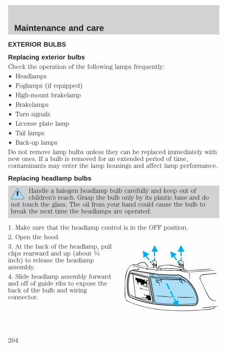
EXTERIOR BULBS
Replacing exterior bulbsCheck the operation of the following lamps frequently:
• Headlamps
• Foglamps (if equipped)
• High-mount brakelamp
• Brakelamps
• Turn signals
• License plate lamp
• Tail lamps
• Back-up lamps
Do not remove lamp bulbs unless they can be replaced immediately withnew ones. If a bulb is removed for an extended period of time,contaminants may enter the lamp housings and affect lamp performance.
Replacing headlamp bulbs
Handle a halogen headlamp bulb carefully and keep out ofchildren’s reach. Grasp the bulb only by its plastic base and do
not touch the glass. The oil from your hand could cause the bulb tobreak the next time the headlamps are operated.
1. Make sure that the headlamp control is in the OFF position.
2. Open the hood.
3. At the back of the headlamp, pullclips rearward and up (about 3⁄4inch) to release the headlampassembly.
4. Slide headlamp assembly forwardand off of guide ribs to expose theback of the bulb and wiringconnector.
Maintenance and care
204

5. Release clip and disconnect theelectrical connector from the bulb.
6. Remove bulb retainer ring byturning it counterclockwise about 1⁄4turn, then slide the ring off theplastic base.
7. Without turning, carefully pull bulb assembly out of headlampassembly and replace.
8. Insert the glass end of the new bulb into the headlamp assembly.When the grooves in the plastic base are aligned, push the bulb into thelamp assembly until the plastic base contacts the rear of the lampassembly.
9. Install bulb retaining ring over the plastic base and lock the ring intothe socket by turning it clockwise until you feel a “stop.”
10. Connect the electrical connector into the plastic base until it “snaps.”
11. Straighten alignment pins, making them parallel with the outer edgesof the attachment standoff.
12. Carefully insert the headlampassembly into the vehicle makingsure the alignment pins are insertedinto the proper holes and into theguide ribs.
13. Hold the headlamp assemblysnugly against the vehicle and pushdown on the clips to lock the lampinto place.
Maintenance and care
205
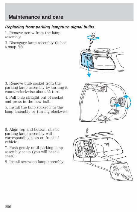
Replacing front parking lamp/turn signal bulbs1. Remove screw from the lampassembly.
2. Disengage lamp assembly (it hasa snap fit).
3. Remove bulb socket from theparking lamp assembly by turning itcounterclockwise about 1⁄4 turn.
4. Pull bulb straight out of socketand press in the new bulb.
5. Install the bulb socket into thelamp assembly by turning clockwise.
6. Align top and bottom ribs ofparking lamp assembly withcorresponding slots on front ofvehicle.
7. Push gently until parking lampassembly seats (you will hear asnap).
8. Install screw on lamp assembly.
Maintenance and care
206
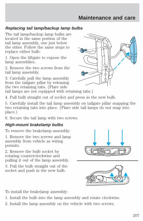
Replacing tail lamp/backup lamp bulbsThe tail lamp/backup lamp bulbs arelocated in the same portion of thetail lamp assembly, one just belowthe other. Follow the same steps toreplace either bulb:
1. Open the liftgate to expose thelamp assemblies.
2. Remove the two screws from thetail lamp assembly.
3. Carefully pull the lamp assemblyfrom the tailgate pillar by releasingthe two retaining tabs. (Flare sidetail lamps are not equipped with retaining tabs.)
4. Pull bulb straight out of socket and press in the new bulb.
5. Carefully install the tail lamp assembly on tailgate pillar snapping thetwo retaining tabs into place. (Flare side tail lamps do not snap intoplace.)
6. Secure the tail lamp with two screws.
High-mount brakelamp bulbsTo remove the brakelamp assembly:
1. Remove the two screws and lampassembly from vehicle as wiringpermits.
2. Remove the bulb socket byrotating counterclockwise andpulling it out of the lamp assembly.
3. Pull the bulb straight out of thesocket and push in the new bulb.
To install the brakelamp assembly:
1. Install the bulb into the lamp assembly and rotate clockwise.
2. Install the lamp assembly on the vehicle with two screws.
Maintenance and care
207
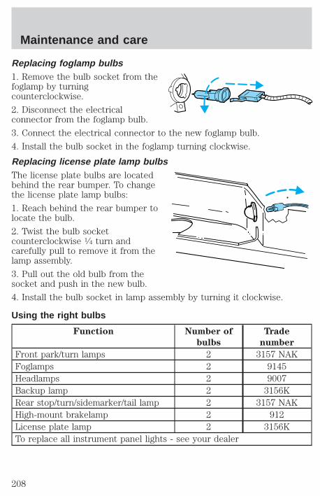
Replacing foglamp bulbs1. Remove the bulb socket from thefoglamp by turningcounterclockwise.
2. Disconnect the electricalconnector from the foglamp bulb.
3. Connect the electrical connector to the new foglamp bulb.
4. Install the bulb socket in the foglamp turning clockwise.
Replacing license plate lamp bulbsThe license plate bulbs are locatedbehind the rear bumper. To changethe license plate lamp bulbs:
1. Reach behind the rear bumper tolocate the bulb.
2. Twist the bulb socketcounterclockwise 1⁄4 turn andcarefully pull to remove it from thelamp assembly.
3. Pull out the old bulb from thesocket and push in the new bulb.
4. Install the bulb socket in lamp assembly by turning it clockwise.
Using the right bulbs
Function Number of
bulbs
Trade
number
Front park/turn lamps 2 3157 NAKFoglamps 2 9145Headlamps 2 9007Backup lamp 2 3156KRear stop/turn/sidemarker/tail lamp 2 3157 NAKHigh-mount brakelamp 2 912License plate lamp 2 3156KTo replace all instrument panel lights - see your dealer
Maintenance and care
208
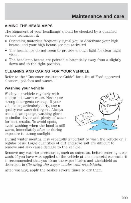
AIMING THE HEADLAMPSThe alignment of your headlamps should be checked by a qualifiedservice technician if:
• Oncoming motorists frequently signal you to deactivate your highbeams, and your high beams are not activated.
• The headlamps do not seem to provide enough light for clear nightvision.
• The headlamp beams are pointed substantially away from a slightlydown and to the right position.
CLEANING AND CARING FOR YOUR VEHICLERefer to the “Customer Assistance Guide” for a list of Ford-approvedcleaners, polishes and waxes.
Washing your vehicleWash your vehicle regularly withcold or lukewarm water. Never usestrong detergents or soap. If yourvehicle is particularly dirty, use aquality car wash detergent. Alwaysuse a clean sponge, washing gloveor similar device and plenty of waterfor best results. To avoid spots,avoid washing when the hood is stillwarm, immediately after or duringexposure to strong sunlight.
During winter months, it is especially important to wash the vehicle on aregular basis. Large quantities of dirt and road salt are difficult toremove and also cause damage to the vehicle.
Remove any exterior accessories, such as antennas, before entering a carwash. If you have wax applied to the vehicle at a commercial car wash, itis recommended that you clean the wiper blades and windshield asdescribed in Cleaning the wiper blades and windshield.
After washing, apply the brakes several times to dry them.
Maintenance and care
209
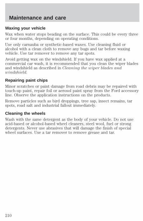
Waxing your vehicleWax when water stops beading on the surface. This could be every threeor four months, depending on operating conditions.
Use only carnauba or synthetic-based waxes. Use cleaning fluid oralcohol with a clean cloth to remove any bugs and tar before waxingvehicle. Use tar remover to remove any tar spots.
Avoid getting wax on the windshield. If you have wax applied at acommercial car wash, it is recommended that you clean the wiper bladesand windshield as described in Cleaning the wiper blades andwindshield.
Repairing paint chipsMinor scratches or paint damage from road debris may be repaired withtouch-up paint, repair foil or aerosol paint spray from the Ford accessoryline. Observe the application instructions on the products.
Remove particles such as bird droppings, tree sap, insect remains, tarspots, road salt and industrial fallout immediately.
Cleaning the wheelsWash with the same detergent as the body of your vehicle. Do not useacid-based or alcohol-based wheel cleaners, steel wool, fuel or strongdetergents. Never use abrasives that will damage the finish of specialwheel surfaces. Use a tar remover to remove grease and tar.
Maintenance and care
210
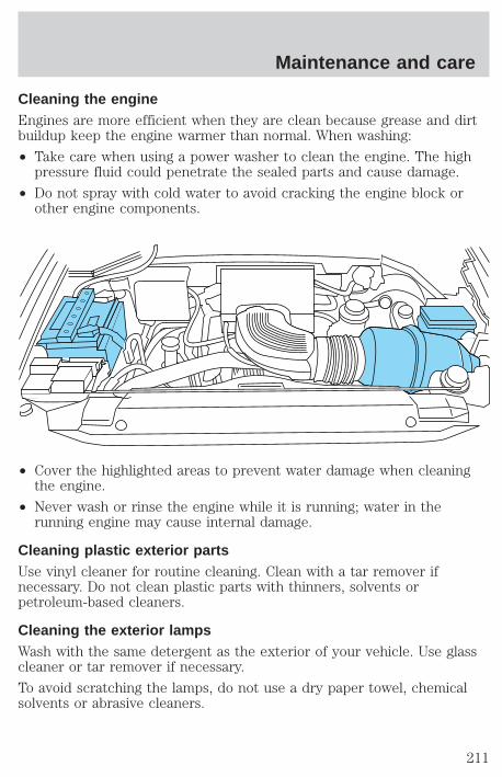
Cleaning the engineEngines are more efficient when they are clean because grease and dirtbuildup keep the engine warmer than normal. When washing:
• Take care when using a power washer to clean the engine. The highpressure fluid could penetrate the sealed parts and cause damage.
• Do not spray with cold water to avoid cracking the engine block orother engine components.
• Cover the highlighted areas to prevent water damage when cleaningthe engine.
• Never wash or rinse the engine while it is running; water in therunning engine may cause internal damage.
Cleaning plastic exterior partsUse vinyl cleaner for routine cleaning. Clean with a tar remover ifnecessary. Do not clean plastic parts with thinners, solvents orpetroleum-based cleaners.
Cleaning the exterior lampsWash with the same detergent as the exterior of your vehicle. Use glasscleaner or tar remover if necessary.
To avoid scratching the lamps, do not use a dry paper towel, chemicalsolvents or abrasive cleaners.
Maintenance and care
211
Cleaning the wiper blades and windshieldIf the wiper blades do not wipe properly, clean the wiper blade rubberelement with undiluted windshield washer solution or a mild detergent.To avoid damaging the blades, do not use fuel, kerosene, paint thinner orother solvents.
If the wiper still does not wipe properly, this could be caused bysubstances on the windshield such as tree sap and some hot waxtreatments used by commercial car washes. Clean the outside of thewindshield with a non-abrasive cleanser such as the non-abrasiveBon-Amit powder. Rinse thoroughly with clean water. Do not useabrasive cleansers on glass as they may cause scratches. The windshieldis clean if beads do not form when you rinse it with water. Thewindshield and wiper blades should be cleaned on a regular basis, andblades or rubber elements replaced when worn.
Cleaning the instrument panelClean with a damp cloth, then dry with a dry cloth.
Avoid cleaner or polish that increases the gloss of the upper portion ofthe instrument panel. The dull finish in this area helps protect the driverfrom undesirable windshield reflection.
Cleaning the interior fabricRemove dust and loose dirt with a whisk broom or a vacuum cleaner.Remove fresh spots immediately. Do not use household or glass cleaners.These agents can stain and discolor the fabric. Use a mild soap andwater solution if necessary.
Maintenance and care
212
Cleaning and maintaining the safety beltsClean the safety belts with a mild soap solution recommended forcleaning upholstery or carpets. Do not bleach or dye the belts, becausethese actions may weaken the belt webbing.
Check the safety belt system periodically to make sure there are nonicks, wear or cuts. If your vehicle has been involved in an accident,refer to the Safety belt maintenance section in the Seating and safetyrestraints chapter.
Cleaning leather seats (if equipped)To clean, simply use a soft cloth dampened with water and a mild soap.Wipe the leather again with a damp cloth to remove soap residue. Drywith a soft cloth. For tougher soiling concerns, Ford recommends usingthe leather cleaning kit F8AJ-19G253–AA, which is available from yourFord Dealer. This mild cleaner and special pad, cleans the leather andmaintains its natural beauty. Follow the instructions on the cleaner label.Regular cleaning of your leather upholstery helps maintain its resiliencyand color.
Do not use household cleaning products, alcohol solutions,solvents or cleaners intended for rubber, vinyl or plastics.
Tonneau cover careTo avoid damage to the vinyl tonneau cover, do not use any siliconebased cleaner or conditioner. Do not use stiff bristle brushes or abrasivematerials or cleaners.
Hot waxes applied by commercial car washes can affect the cleanabilityof vinyl material.
Using high water pressure or wand-type car washes against the vinylcover and tonneau frame rails may cause water leaks and possible sealdamage.
Maintenance and care
213
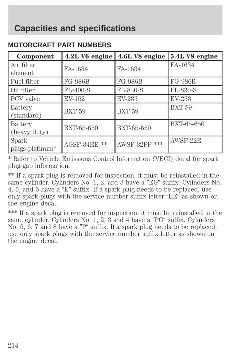
MOTORCRAFT PART NUMBERS
Component 4.2L V6 engine 4.6L V8 engine 5.4L V8 engine
Air filterelement
FA-1634 FA-1634FA-1634
Fuel filter FG-986B FG-986B FG-986BOil filter FL-400-S FL-820-S FL-820-SPCV valve EV-152 EV-233 EV-233Battery(standard)
BXT-59 BXT-59BXT-59
Battery(heavy duty)
BXT-65-650 BXT-65-650BXT-65-650
Sparkplugs-platinum*
AGSF-34EE ** AWSF-32PP ***AWSF-22E
* Refer to Vehicle Emissions Control Information (VECI) decal for sparkplug gap information.
** If a spark plug is removed for inspection, it must be reinstalled in thesame cylinder. Cylinders No. 1, 2, and 3 have a 9EG9 suffix. Cylinders No.4, 5, and 6 have a 9E9 suffix. If a spark plug needs to be replaced, useonly spark plugs with the service number suffix letter 9EE9 as shown onthe engine decal.
*** If a spark plug is removed for inspection, it must be reinstalled in thesame cylinder. Cylinders No. 1, 2, 3 and 4 have a 9PG9 suffix. CylindersNo. 5, 6, 7 and 8 have a 9P9 suffix. If a spark plug needs to be replaced,use only spark plugs with the service number suffix letter as shown onthe engine decal.
Capacities and specifications
214

REFILL CAPACITIES
FluidFord PartName
Application Capacity
Brake fluid
HighPerformanceDOT 3MotorVehicleBrake Fluid
All Fill to line onreservoir
Enginecoolant1
PremiumEngineCoolant
4.2L V6 engine with1 row radiator
19.0L (20.1 quarts)
4.2L V6 engine with2 row radiator
20.4L (21.6 quarts)
4.6L V8 engine with1 row radiator
19.5L (20.6 quarts)
4.6L V8 engine with2 row radiator
21.9L (23.1 quarts)
5.4L V8 engine with1 row radiator
22.6L (23.9 quarts)
5.4L V8 engine with2 row radiator
24.1L (25.5 quarts)
Engine oil(includesfilterchange)
Motorcraft5W30 SuperPremiumMotor Oil
All 5.7L (6.0 quarts)
Fuel tank N/A
4x4 Reg. Cab shortwheelbase
92.7L (24.5 gallons)
4x2 Regular Caband all SuperCabshort wheelbase
94.6L (25.0 gallons)
Long Wheelbase 113.6L (30.0 gallons)Powersteeringfluid
MotorcraftMERCONtATF
All Fill to line onreservoir
Transfercase fluid2
MotorcraftMERCONtATF
4x4 vehicles 1.9L (2.0 quarts)
Capacities and specifications
215
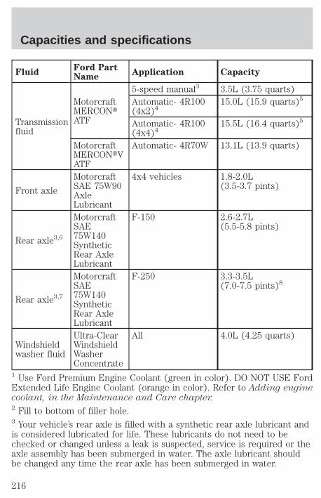
FluidFord PartName
Application Capacity
Transmissionfluid
MotorcraftMERCONtATF
5-speed manual3 3.5L (3.75 quarts)Automatic- 4R100(4x2)4
15.0L (15.9 quarts)5
Automatic- 4R100(4x4)4
15.5L (16.4 quarts)5
MotorcraftMERCONtVATF
Automatic- 4R70W 13.1L (13.9 quarts)
Front axle
MotorcraftSAE 75W90AxleLubricant
4x4 vehicles 1.8-2.0L(3.5-3.7 pints)
Rear axle3,6
MotorcraftSAE75W140SyntheticRear AxleLubricant
F-150 2.6-2.7L(5.5-5.8 pints)
Rear axle3,7
MotorcraftSAE75W140SyntheticRear AxleLubricant
F-250 3.3-3.5L(7.0-7.5 pints)8
Windshieldwasher fluid
Ultra-ClearWindshieldWasherConcentrate
All 4.0L (4.25 quarts)
1 Use Ford Premium Engine Coolant (green in color). DO NOT USE FordExtended Life Engine Coolant (orange in color). Refer to Adding enginecoolant, in the Maintenance and Care chapter.2 Fill to bottom of filler hole.3 Your vehicle’s rear axle is filled with a synthetic rear axle lubricant andis considered lubricated for life. These lubricants do not need to bechecked or changed unless a leak is suspected, service is required or theaxle assembly has been submerged in water. The axle lubricant shouldbe changed any time the rear axle has been submerged in water.
Capacities and specifications
216
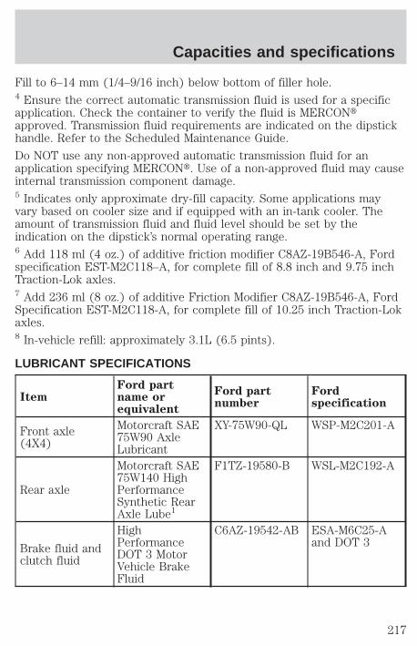
Fill to 6–14 mm (1/4–9/16 inch) below bottom of filler hole.4 Ensure the correct automatic transmission fluid is used for a specificapplication. Check the container to verify the fluid is MERCONtapproved. Transmission fluid requirements are indicated on the dipstickhandle. Refer to the Scheduled Maintenance Guide.
Do NOT use any non-approved automatic transmission fluid for anapplication specifying MERCONt. Use of a non-approved fluid may causeinternal transmission component damage.5 Indicates only approximate dry-fill capacity. Some applications mayvary based on cooler size and if equipped with an in-tank cooler. Theamount of transmission fluid and fluid level should be set by theindication on the dipstick’s normal operating range.6 Add 118 ml (4 oz.) of additive friction modifier C8AZ-19B546-A, Fordspecification EST-M2C118–A, for complete fill of 8.8 inch and 9.75 inchTraction-Lok axles.7 Add 236 ml (8 oz.) of additive Friction Modifier C8AZ-19B546-A, FordSpecification EST-M2C118-A, for complete fill of 10.25 inch Traction-Lokaxles.8 In-vehicle refill: approximately 3.1L (6.5 pints).
LUBRICANT SPECIFICATIONS
ItemFord partname orequivalent
Ford partnumber
Fordspecification
Front axle(4X4)
Motorcraft SAE75W90 AxleLubricant
XY-75W90-QL WSP-M2C201-A
Rear axle
Motorcraft SAE75W140 HighPerformanceSynthetic RearAxle Lube1
F1TZ-19580-B WSL-M2C192-A
Brake fluid andclutch fluid
HighPerformanceDOT 3 MotorVehicle BrakeFluid
C6AZ-19542-AB ESA-M6C25-Aand DOT 3
Capacities and specifications
217
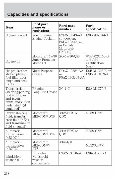
ItemFord partname orequivalent
Ford partnumber
Fordspecification
Engine coolant Ford PremiumEngine Coolant
E2FZ-19549-AA(in Oregon,F5FZ-19549-CC,in Canada,MotorcraftCXC-10)
ESE-M97B44-A
Engine oil
Motorcraft 5W30Super PremiumMotor Oil
XO-5W30-QSP WSS-M2C153-Gand APICertificationMark
Hinges, latches,striker plates,fuel filler doorhinge and seattracks.
Multi-PurposeGrease
DOAZ-19584-AAorF5AZ-19G209-AA
ESB-M1C93-B orESB-M1C159-A
Transmission/steering/parkingbrake linkagesand pivots,brake and clutchpedal shaft (ifequipped)
PremiumLong-Life Grease
XG-1-C ESA-M1C75-B
Power steeringfluid, transfercase fluid (4X4)and transmissionfluid (manual)
MotorcraftMERCONt ATF
XT-2-BDX orQDX
MERCONt
Automatictransmission(4R100)2
MotorcraftMERCONt ATF
XT-2-BDX orQDX
MERCONt
Automatictransmission(4R70W)
MotorcraftMERCONtVATF
XT-5-QMMERCONtV
Windshieldwasher fluid
Ultra-clearwindshieldwasherconcentrate
C9AZ-19550-AC ESR-M17P5-A
Capacities and specifications
218

1 Add 118 ml (4 oz.) of additive friction modifier C8AZ-19B546–A, Fordspecification EST-M2C118–A for complete refill of 8.8 inch and 9.75 inchTraction-Lok axles. Add 236 ml (8 oz.) of additive friction modifierC8AZ-19B546–A, Ford specification EST-M2C118–A for complete refill of10.25 and 10.5 inch Traction-Lok axles.2 Refer to the dipstick for the type of transmission fluid required. Somefluid labels may indicate dual usage such as MERCONt and MERCONVt. These dual usage fluids are not to be used in transmissions that useonly the MERCONt type fluid. These dual usage fluids may be used intransmissions that require MERCONt V use.
Using a transmission fluid that indicates a dual usage (MERCONt andMERCON Vt) in a transmission application requiring MERCONt maycause transmission damage. Use of any fluid other than therecommended fluid may cause transmission damage.
ENGINE DATA
Engine 4.2L V6 engine 4.6L V8 engine 5.4L V8 engine
Cubic inches 256 281 330
Horsepower 205 @ 4750 rpm 220 @ 4500rpm1
250 @ 4500 rpm
Torque 250 lb.-ft. @3000 rpm
290 lb.-ft. @3250 rpm
345 lb.-ft. @2250 rpm
Recommendedfuel
87 octane 87 octane 87 octane
Firing order 1-4-2-5-3-6 1-3-7-2-6-5-4-8 1-3-7-2-6-5-4-8
Spark plug gap1.3-1.4 mm(0.052-0.056inch)
1.3-1.4 mm(0.052-0.056inch)
1.3-1.4 mm(0.052-0.056inch)
Ignition system EDIS EDIS Coil on plugCompressionratio
9.3:1 9.0:1 9.0:1
1 All F150 vehicles and F250 with manual transmission. F250 withautomatic transmission is 235 hp @ 4400 rpm.
Capacities and specifications
219
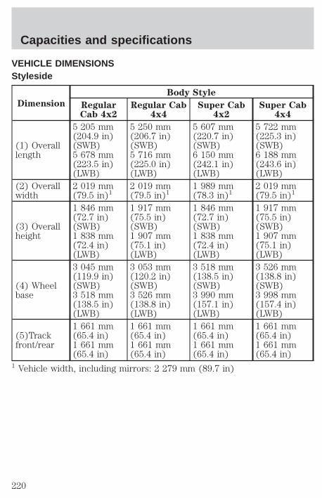
VEHICLE DIMENSIONSStyleside
Dimension
Body Style
RegularCab 4x2
Regular Cab4x4
Super Cab4x2
Super Cab4x4
(1) Overalllength
5 205 mm(204.9 in)(SWB)5 678 mm(223.5 in)(LWB)
5 250 mm(206.7 in)(SWB)5 716 mm(225.0 in)(LWB)
5 607 mm(220.7 in)(SWB)6 150 mm(242.1 in)(LWB)
5 722 mm(225.3 in)(SWB)6 188 mm(243.6 in)(LWB)
(2) Overallwidth
2 019 mm(79.5 in)1
2 019 mm(79.5 in)1
1 989 mm(78.3 in)1
2 019 mm(79.5 in)1
(3) Overallheight
1 846 mm(72.7 in)(SWB)1 838 mm(72.4 in)(LWB)
1 917 mm(75.5 in)(SWB)1 907 mm(75.1 in)(LWB)
1 846 mm(72.7 in)(SWB)1 838 mm(72.4 in)(LWB)
1 917 mm(75.5 in)(SWB)1 907 mm(75.1 in)(LWB)
(4) Wheelbase
3 045 mm(119.9 in)(SWB)3 518 mm(138.5 in)(LWB)
3 053 mm(120.2 in)(SWB)3 526 mm(138.8 in)(LWB)
3 518 mm(138.5 in)(SWB)3 990 mm(157.1 in)(LWB)
3 526 mm(138.8 in)(SWB)3 998 mm(157.4 in)(LWB)
(5)Trackfront/rear
1 661 mm(65.4 in)1 661 mm(65.4 in)
1 661 mm(65.4 in)1 661 mm(65.4 in)
1 661 mm(65.4 in)1 661 mm(65.4 in)
1 661 mm(65.4 in)1 661 mm(65.4 in)
1 Vehicle width, including mirrors: 2 279 mm (89.7 in)
Capacities and specifications
220
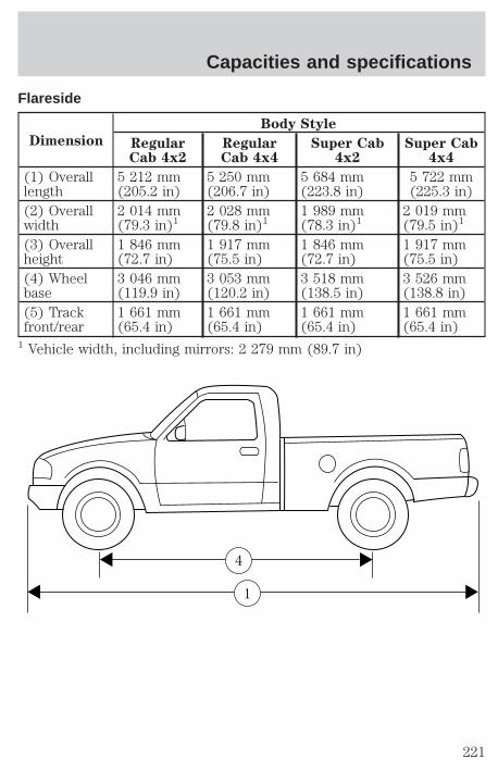
Flareside
Dimension
Body Style
RegularCab 4x2
RegularCab 4x4
Super Cab4x2
Super Cab4x4
(1) Overalllength
5 212 mm(205.2 in)
5 250 mm(206.7 in)
5 684 mm(223.8 in)
5 722 mm(225.3 in)
(2) Overallwidth
2 014 mm(79.3 in)1
2 028 mm(79.8 in)1
1 989 mm(78.3 in)1
2 019 mm(79.5 in)1
(3) Overallheight
1 846 mm(72.7 in)
1 917 mm(75.5 in)
1 846 mm(72.7 in)
1 917 mm(75.5 in)
(4) Wheelbase
3 046 mm(119.9 in)
3 053 mm(120.2 in)
3 518 mm(138.5 in)
3 526 mm(138.8 in)
(5) Trackfront/rear
1 661 mm(65.4 in)
1 661 mm(65.4 in)
1 661 mm(65.4 in)
1 661 mm(65.4 in)
1 Vehicle width, including mirrors: 2 279 mm (89.7 in)
1
4
Capacities and specifications
221
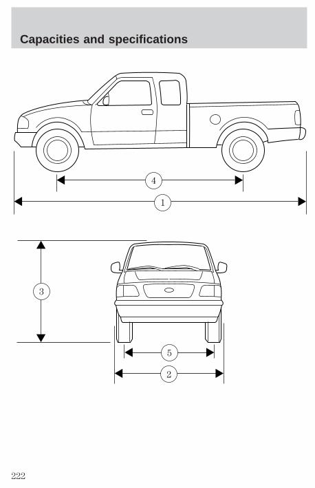
1
4
2
5
3
Capacities and specifications
222

IDENTIFYING YOUR VEHICLE
Safety compliance labelThe National Highway Traffic SafetyAdministration Regulations requirethat a Safety ComplianceCertification Label be affixed to avehicle and prescribe where theSafety Compliance CertificationLabel may be located. The SafetyCompliance Certification Label islocated on the front door latch pillaron the driver’s side.
Vehicle identification numberThe vehicle identification number isattached to a metal tag and islocated on the driver sideinstrument panel.
Engine numberThe engine number (the last eight numbers of the vehicle identificationnumber) is stamped on the engine block and transmission.
MFD. BY FORD MOTOR CO. IN U.S.A.
EXT PNT: XXXXXX XXXXXX RC: XX DSO: XXXX F0000BAR INT TR TP/PS R AXLE TR SPR T0000 X XX XXX X XX X XXXX
UTC ∇FOHT-15294A10-GA
MAXIMUM LOAD=OCCUPANTS + LUGGAGE=XXXKG/XXXXLBOCCUPANTS: X TOTAL X FR X 2ND X RR OCCUPANTS LUGGAGE
XX XXXKG/XXXXLBTIRE: XXXX/XXXXX XXX X XXXKG/XXXXLBPRESSURE (FR) XXX kPa/33 PSI COLDPRESSURE (RR) XXX kPa/33 PSI COLDTRAILER TOWING - SEE OWNER GUIDE
DATE: XXXXX GVWR:XXXXX LB/ XXXXX KG
VIN: XXXXXXXXXXXXXXXXX TYPE: XXXXXXXXXXXXXXX
FGAWR: XXXXXX/XXXXXXX RGAWR: XXXXXXX/XXXXXXXTHIS VEHICLE CONFORMS TO ALL APPLICABLE FEDERALMOTOR VEHICLE SAFETY STANDARDS IN EFFECT ON THEDATE OF MANUFACTURE SHOWN ABOVE.
XXXXXXXXXXXXXXXXX
AIR BAG
Capacities and specifications
223
REPORTING SAFETY DEFECTS (U.S. ONLY)If you believe that your vehicle hasa defect that could cause a crash, orcould cause injury or death, youshould immediately inform theNational Highway Traffic SafetyAdministration (NHTSA) in additionto notifying Ford Motor Company.
If NHTSA receives similar complaints, it may open an investigation, andif it finds that a safety defect exists in a group of vehicles, it may order arecall and remedy campaign. However, NHTSA cannot become involvedin individual problems between you, your dealer or Ford Motor Company.
To contact NHTSA, you may either call the Auto Safety Hotline toll-freeat 1–800–424–9393 (202–366–0123 in the Washington D.C. area) or writeto:
NHTSAU.S. Department of Transportation400 Seventh StreetWashington D.C. 20590
You can also obtain other information about motor vehicle safety fromthe Hotline.
Reporting safety defects
224

Accessory delay ..........................70Air bag supplemental restraintsystem ..........................................95
and child safety seats ..............96description ................................95disposal ......................................98indicator light ...........................98passenger air bag .....................96passenger deactivationswitch ..............61,99,100,101,102
Air cleaner filter ................188,189Air suspension ...........................119
warning light .............................11Anti-theft system ..............76,77,78Armrests ......................................88Automatic transmission
driving an automaticoverdrive ...................121,122,123
Axlerefill capacities ........................215
Batteryvoltage gauge ............................14
Brakes ........................................115anti-lock ............................115,116anti-lock brake system(ABS) warning light ...............116fluid, checking and adding ....174shift interlock ..........................120
Break-in period .............................2CD player .....................52,54,55,56Child safety seats
attaching with tether straps ..109in rear seat .......................106,108tether anchorage hardware ...109
Cleaning your vehicle ...............209engine compartment ..............211exterior .............................210,213exterior lamps .........................211interior .....................................212plastic parts ............................211washing ....................................209waxing .....................................210
wheels ......................................210wiper blades ............................212
Clutchfluid ..........................................175operation while driving ..........123recommendedshift speeds ......................125,126
Controlspower seat .................................86
Coolant ...............................178,179checking and adding ..............177refill capacities ........................179
Driveline universal joint andslip yoke ....................................186Driving under specialconditions ...........................132,133
sand .........................................132snow and ice ...........................133through water .........................132
Emission control system ..........202Engine
coolant .....................................177idle speed control ...................186service points ...................170,171starting after a collision .........149
Engine block heater .................113Engine oil
checking and adding ..............173dipstick ....................................172specifications ...................172,174
Exhaust fumes ..........................113Fail safe cooling .................179,180Four-Wheel Drive vehicles ..10,128
description .......................130,131driving off road .......................131electronic shift ...................18,130indicator light ....................10,128lever operated shift ..128,129,130
Fuelchoosing the right fuel ...........196comparisons with EPA fueleconomy estimates .................202
Index
225
detergent in fuel .....................197filling your vehiclewith fuel ...........................195,198quality ......................................197running out of fuel .................197safety information relating toautomotive fuels .....................195
Fuses ...................................150,151Gas mileage(see Fuel economy) ...199,200,201Gauges .........................................12
engine coolant temperaturegauge .........................................13engine oil pressure gauge ........15fuel gauge ..................................12
GVWR(Gross Vehicle Weight Rating)
calculating ...............................135Hazard flashers .........................149Headlamps
aiming ......................................209bulb specifications ..................208high beam ..............................9,68warning chime ..........................11
Heating ........................................56heater only system ..............56,57heating and airconditioning system ............58,60
Hood ..........................................169Ignition .......................................219Inspection/maintenance(I/M) testing ..............................203Instrument panel ..........................6
cleaning ...................................212Keys
key in ignition chime ...............11positions of the ignition ...........61removing from the ignition ....127
Lampsautolamp system .......................17daytime running light ...............16fog lamps ...................................16
headlamps .................................16headlamps, flash to pass ..........68instrument panel, dimming .....17interior lamps ...........................69replacing bulbs ..204,206,207,208
Lane change indicator(see Turn signal) ........................62Lights, warning and indicator
air bag ..........................................8air suspension .........................119anti-lock brakes (ABS) ..............9anti-theft .....................................9brake ............................................8charging system ..........................9door ajar ....................................11engine oil pressure ...................10fuel reset ...................................11low fuel ........................................6safety belt ...................................8service engine soon ....................7turn signal indicator ...................9
Lumbar support, seats ..........87,88Manual transmission
reverse .....................................127Mirrors
fold away ...................................72side view mirrors (power) .......71
Motorcraft parts ........................198Octane rating ............................197Odometer .....................................13Overdrive .....................................68Parking brake ............................117Power distribution box(see Fuses) ...............................154Power door locks ..............70,80,81Power steering ..........................118
fluid,checking and adding .......181,182
Radio ....19,20,21,22,24,25,26,27,2829,30,31,33,34,35,36
Relays ........................................150Remote entry system ............79,80
Index
226
illuminated entry ......................83locking/unlocking doors ...........79replacement/additionaltransmitters ...............................82replacing the batteries .............81
Safety belts (see Safetyrestraints) ....................................11Safety ComplianceCertification Label ....................223Safety defects, reporting ..........224Safety restraints
cleaning the safety belts ...94,213extension assembly ..................93for children .............................103lap belt ......................................92warning light and chime .....93,94
Seat belts (see Safetyrestraints) .....................89,90,91,92Seats ..................................84,85,86
child safety seats ....................104cleaning ...................................213
Servicing your vehicle .......168,169Snowplowing ............3,145,146,147Spark plugs, specifications .......214Special notice ................................3
ambulance conversions ..............3four-wheel drivevehicles .............................147,148utility-type vehicles ....................3
Specification chart,lubricants ...................................217Speed control ..............................62Speedometer ...............................13Starting your vehicle .........110,112
jump starting ............162,163,165Steering wheel
tilting .........................................66Tachometer .................................14Tailgate ...................................72,73Tires .............................190,191,192
changing ...........................157,158checking the pressure ............192replacing ..................................193rotating ....................................192snow tires and chains ............194tire grades ...............................191treadwear ................................191
Towingrecreational towing ..........144,145wrecker ....................................167
Traction-lok rear axle ...............118Transfer case
fluid checking .........................185Transmission
automatic operation ...............120fluid, checking and adding(automatic) ...............182,183,184fluid, checking and adding(manual) .................................184manual operation ....................123
Transmission controlindictor light ................................10Trip odometer .............................14Vehicle dimensions ...................220Vehicle Identification Number(VIN) ..........................................223Vehicle loading ..........................134Ventilating your vehicle ...........114Warning chimes ........................6,11Washer fluid ..............................176Water,Driving through ....136,137,138,139
140,141,142,143Windows .................................69,70Windshield washer fluidand wipers
checking and cleaning ............189operation ...................................67replacing wiper blades ...........190
Index
227

228

229

230

231
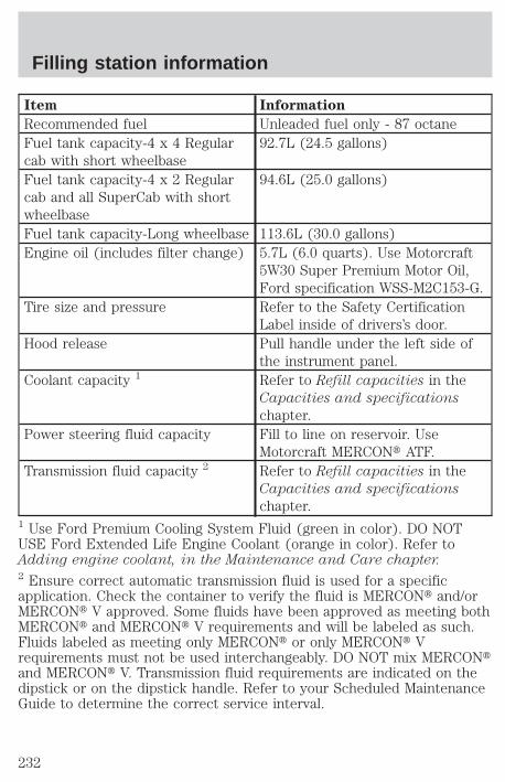
Item Information
Recommended fuel Unleaded fuel only - 87 octaneFuel tank capacity-4 x 4 Regularcab with short wheelbase
92.7L (24.5 gallons)
Fuel tank capacity-4 x 2 Regularcab and all SuperCab with shortwheelbase
94.6L (25.0 gallons)
Fuel tank capacity-Long wheelbase 113.6L (30.0 gallons)Engine oil (includes filter change) 5.7L (6.0 quarts). Use Motorcraft
5W30 Super Premium Motor Oil,Ford specification WSS-M2C153-G.
Tire size and pressure Refer to the Safety CertificationLabel inside of drivers’s door.
Hood release Pull handle under the left side ofthe instrument panel.
Coolant capacity 1 Refer to Refill capacities in theCapacities and specifications
chapter.Power steering fluid capacity Fill to line on reservoir. Use
Motorcraft MERCONt ATF.Transmission fluid capacity 2 Refer to Refill capacities in the
Capacities and specifications
chapter.1 Use Ford Premium Cooling System Fluid (green in color). DO NOTUSE Ford Extended Life Engine Coolant (orange in color). Refer toAdding engine coolant, in the Maintenance and Care chapter.2 Ensure correct automatic transmission fluid is used for a specificapplication. Check the container to verify the fluid is MERCONt and/orMERCONt V approved. Some fluids have been approved as meeting bothMERCONt and MERCONt V requirements and will be labeled as such.Fluids labeled as meeting only MERCONt or only MERCONt Vrequirements must not be used interchangeably. DO NOT mix MERCONtand MERCONt V. Transmission fluid requirements are indicated on thedipstick or on the dipstick handle. Refer to your Scheduled MaintenanceGuide to determine the correct service interval.
Filling station information
232