Радиально-поршневые гидромоторы hägglunds ca bosch rexroth
TRANSCRIPT

Compact CAP R O D U C T M A N U A L


Product Manual
COMPACT EN396-10h 2011

4
Worldwide distribution and service organization
Orig
inal
EN
396-
9h, 2
009
One partner all over the world
Hägglunds Drivesis the worlds leading manufacturer of heavy duty hydraulic drive systems. If what you need is low speed and high torque, then Hägglunds Drives should be your partner. If what you need is a durable drive system that will work under the toughest conditions with a minimum of maintenance, then Hägglunds Drives should be your partner. We develop, manufacture & market complete drive systems and components of the highest quality, based upon our unique radial piston motors. Our industrial and marine customers are to be found all over the world. They know that when they need solutions, support or service, they have in us a partner they can trust. Hägglunds Drives main office and manufacturing plant is situated in Mellansel, Sweden. In Addition Hägglunds is represented in 40 countries worldwide.
The content in this manual is subject to change without notice or obligation, unless certified referring to a certain purchase order. Information contained herein should be confirmed before placing orders.

5
Features
High power capacity The new Compact has a wider speed range than any motor we have built before. It can work at high speed and high pressure, check out the efficiency curves on page 15.
Adaptable mountingEven through we believe in standard solutions. We also believe in adapting our products to our custom-ers needs. The new Compact can be mounted in just about any way you want it.
High power/weight ratioThe new Compact with it´s small outer diameter and low weight will give you a high power to weight ratio that is extraordinary. This means great performance but also lower energy consumption.
Insensitive to shock loadsThe new Compact is small and light but at the same time tough and insensitive to shock loads. The new Compact has everything you have come to expect from a Hägglunds motor - high torque, wide speed range, shock resistant, easy to install, easy to main-tain, and as tough as they come. - Only smaller!
Hole through motor centreThe hole through the motor centre is extremely use-ful in some applications. For example with through shaft for driving from both ends - or to gain access to the machine to feed water or other medium through the shaft.
Quick selection diagram for Compact motorsThe diagram below represents the torque and speed, corresponding to a basic rating life L10aah= 20 000 h. Oil viscosity in the motor case 40 cSt (187 SSU). When operating below 5 rpm, coated pistons or oil with higher viscosity shall be used. Contact your Hägglunds representative.
For operation outside of or in the line screened area, please contact your Hägglunds representative.
0
CA 140
CA 100
CA 70
CA 50
CA 210
Torq
ue lb
f·ft x
103

6
Functional description
1
2
3
4
5
6
7
D
8
A, C
10
9
11
Quality
To assure our quality we maintain a Quality Assurance System, certified to standard ISO 9001, EN 29001 and BS 5750; Part 1.
1. Cam ring2. Cam roller3. Piston4. Shaft coupling5. Cylinder block / hollow shaft6. Cylinder block / spline7. Shaft end housing8. Cylinder roller bearings9. Connection block10. Valve plate11. Cylinder roller thrust bearing
A = Inlet or outlet port »A« (2 each)C = Inlet or outlet port »C«D = Drain port (3 each)F4 = Flushing
1
2
3
5
10
Fig. 1 Compact motor
Valid patents
US 4522110, US 005979295A, SE 456517, EP 0102915, JP 83162704, GB 1385693, EP 0524437.
F4
Hägglunds hydraulic industrial and marine motor COMPACT is of the radial-piston type with a rotating cylinder block/hollow shaft and a stationary housing. The cylinder block is mounted in fixed roller bearings in the housing. An even number of pistons are radially located in bores inside the cylinder block, and the valve plate directs the incoming and outgoing oil to and from the working pistons. Each piston is working against a cam roller.
When the hydraulic pressure is acting on the pistons, the cam rollers are pushed against the slope on the cam ring that is rigidly connected to the housing, thereby producing a torque. The cam rollers transfer the reaction force to the pistons which are guided in the cylinder block. Rotation therefore occurs, and the torque available is proportional to the pressure in the system.
Oil main lines are connected to ports A and C in the connection block and drain lines to ports D1, D2 or D3 in the motor housing.
The motor is connected to the shaft of the driven machine through the hollow shaft of the cylinder block. The torque is transmitted by using a mechanical shrink disc, or alternatively by splines. The symmetrical design of the motor has made it possible to design it as a two displacement motor. This means that two different displacements and speeds can be obtained for a given flow. To get the 2-speed function, a motor prepared for two speeds has to be ordered together with a 2-speed valve.

7
Calculation fundamentals
Outputpower
Output speed
Flowrate required
Pressure required
Output torque*
Inlet power (kW)
(rpm)
(l/min) (gpm)
(bar)
(Nm)
P= (hp)ondrivenshaftT n·
5252
p p p= + +�T
T ·�p p p= + +�
T·10001000
T ·�
P= P=
q p p· -( )600
q p p· -( )1714
T T p p p= ·( - - )·� �T p p p·( - - )·� �
n= n=q-qV
q-qV
P= (kW)ondrivenshaftT n·
9549
q q= +
· 1000
1000
· 231
q q= +231
(hp)
(lbf·ft)
(psi)
T=
n V· n V·
(rpm)
s l c m
S ml c
il
s l c m
s ml c
il
l
i
cc
i
l
in in
( =98%)�m
( = 98%)�m
For more informationSee Powerful Engineering
(EN347-4).
Quantity Symbol Metric US
Quantity Symbol Metric USPower P = kW hpOutput torque T = Nm lbf·ftSpecific torque Ts = Nm/bar lbf·ft/1000 psiRotational speed n = rpm rpmRequired pressure p = bar psi
Pressure loss ∆pl = bar psiCharge pressure pc = bar psiFlow rate required q = l/min gpmTotal volumetric loss ql = l/min gpmDisplacement Vi = cm3/rev in3/revMechanical efficiency ηm = 0.97 (Not valid for starting efficiency)
Data
Rated speed1)
Rated speed is the highest allowed speed for a charge pressure of 12 bar (175 psi) above case pressure. When a closed loop system is used, a minimum of 15% of oil is to be exchanged in the main loop.
Max speed Maximum speed is the maximum allowed speed. Special considerations are nece-ssary regarding charge pressure, cooling and choice of hydraulic system for speeds rated above.
Accepted conditions for standard type of motor:1. Oil viscosity 20 - 40 - 10000 cSt (98 - 187 - 4650 SSU). See page 24.2. Temperature -35°C to +70°C (-31°F to +158°F). 3. Running case pressure 0-3 bar (0-45 psi) Max case pressure 8 bar (116 psi) 4. Charge pressure (see diagram). 5. Volumetric losses (see diagram).
Definitions
1)Operating above rated conditions requires Hägglunds approval.
*Related to a required charge pressure of 12 bar/175 psi for motors in braking mode. (Special considerations regarding charge pressure, cooling and choice of hydraulic system for speeds above rated, 4 ports must be used for higher speed).**The motors are designed according to DNV-rules. Test pressure 420 bar/6000 psi. Peak/transient pressure 420 bar/6000 psi maximum, allowed to occur 10000 times.***Speed above 280 rpm requires viton seals. Max permitted continues case pressure is 2 bar.
Motor type FULL DISPLACEMENT Max. ** pressure
DISPLACEMENT SHIFT
Displace-ment
Specific torque
Rated*speed
Max. *** speed
Displace-ment
Specific torque
Rated speed
Max. speed
Ratio
psi
CA 50 20 76.6 1017 400 400 5000
CA 50 25 95.8 1271 350 400 5000
CA 50 32 122.6 1627 280 400 5000
CA 50 40 153.3 2034 230 350 5000
CA 50 191.6 2543 200 280 5000 95.8 1271 200 280 1:2
CA 70 40 153.3 2034 270 400 5000
CA 70 50 191.6 2543 225 320 5000 95.8 1271 225 320 1:2
CA 70 60 230.1 3051 195 275 5000 115.1 1526 195 275 1:2
CA 70 268.5 3560 180 240 5000 134.3 1780 180 240 1:2
CA 100 40 153.3 2034 390 400 5000
CA 100 50 191.6 2543 320 400 5000
CA 100 64 245.3 3254 260 390 5000
CA 100 80 306.6 4068 220 310 5000 153.3 2034 220 310 1:2
CA 100 383.2 5085 190 270 5000 191.6 2543 190 270 1:2
CA 140 80 306.6 4068 245 340 5000
CA 140 100 383.2 5085 205 275 5000 191.6 2543 205 275 1:2
CA 140 120 460.3 6102 180 245 5000 230.1 3050 180 245 1:2
CA 140 537 7119 170 220 5000 268.5 3560 170 220 1:2
CA 210 160 613.2 8136 105 150 5000 306.7 4068 105 150 1:2
CA 210 180 690.4 9154 100 135 5000 345.2 4577 100 135 1:2
CA210 805.5 10678 85 115 5000 402.8 5339 85 115 1:2
Motor type FULL DISPLACEMENT Max. ** pressure
DISPLACEMENT SHIFT
Displace-ment
Specific torque
Rated* speed
Max.*** speed
Displace-ment
Specific torque
Rated speed
Max. speed
Ratio
bar
CA 50 20 1256 20 400 400 350
CA 50 25 1570 25 350 400 350
CA 50 32 2010 32 280 400 350
CA 50 40 2512 40 230 350 350
CA 50 3140 50 200 280 350 1570 25 200 280 1:2
CA 70 40 2512 40 270 400 350
CA 70 50 3140 50 225 320 350 1570 25 225 320 1:2
CA 70 60 3771 60 195 275 350 1886 30 195 275 1:2
CA 70 4400 70 180 240 350 2200 35 180 240 1:2
CA 100 40 2512 40 390 400 350
CA 100 50 3140 50 320 400 350
CA 100 64 4020 64 260 390 350
CA 100 80 5024 80 220 310 350 2512 40 220 310 1:2
CA 100 6280 100 190 270 350 3140 50 190 270 1:2
CA 140 80 5024 80 245 340 350
CA 140 100 6280 100 205 275 350 3140 50 205 275 1:2
CA 140 120 7543 120 180 245 350 3771 60 180 245 1:2
CA 140 8800 140 170 220 350 4400 70 170 220 1:2
CA 210 160 10051 160 105 150 350 5026 80 105 150 1:2
CA 210 180 11314 180 100 135 350 5657 90 100 135 1:2
CA 210 13200 210 85 115 350 6600 105 85 115 1:2
cm3 Nm rev rev cm3 Nm rev rev
rev bar min min rev bar min min
US
Metric
Not recommended to be used in reduced displacement
Not recommended to be used in reduced displacement
Vi Ts n n p Vi Ts n n in3 lbf·ft rev rev in3 lbf·ft rev rev
rev 1000 psi min min rev 1000 psi min min
Vi Ts n n p Vi Ts n n

8
Ordering codes
In order to identify Hägglunds equipment exactly, the following ordering code is used. These ordering codes should be stated in full in all correspondence e.g. when ordering spare parts.
Compact motors
and coated cam rollers
M D A 0 5 N 1 0 0M D
Multidisc brake
Generation
Brake size
Type of seal
Modification
Design
NitrileViton
StandardSpecial index
Example:
MDA 5MDA 7MDA 10MDA 14*MDA 21*
0001-99
NV
1-9
Brake must be ordered separately
To be filled in by Hägglunds
PaintingOrangeOther
StandardOption
*MDA 14 and MDA 21, designed for separate mounting on the driven shaft.MDA 14 can be mounted directly to the motor via Tandem kit 21, this is notpossible with MDA 21.
Torque arm
Torque arm
Generation
Torque armsize
Attachment
Modification
Design
PivotedOther
StandardSpecial index
Example:
TCA 5 (for CA 50)TCA 7 (for CA 70)TCA 10 (for CA 100)TCA 14* (for CA 140/210)
0001-99
29
0-9
To be filled in by Hägglunds
T C A 5 - 0 - 0 - 0 0T C - - -
*Also for CA 210Note:Torque arm incl. Pivot attachment.
TCA 5/7 - bolts supplied with motor.TCA 10/14 - bolts & washers supplied with torque arm.
Multi Disc Brake (MDA)

9
Ordering codes
In order to identify Hägglunds equipment exactly, the following ordering code is used. These ordering codes should be stated in full in all correspondence e.g. when ordering spare parts.
Speed encoder Mounting set for speed encoder
2-Speed valve
P D B 1 - 1000
Speed encoder
Digital
Generation
Type of encoder
Pulse rate (pulse/rev)10003600
Standard 1Explosion proof 2
Example: SP D B -S
S M C B 1 0 0 0S M C
Mounting set forspeed encoder
For motors
Generation B
Type of encoder
Modification
Design
Compact
Standard 1Explosion proof 3
0-9
StandardSpecial index
C
Example:
0001-99
To be filled in by Hägglunds
--

10
Motor CA50/70 CA100/140 CA210
Toth profile and bottom form
DIN 5480 DIN 5480 DIN 5480
Tolerance 8f 8f 8f
Guide Back Back Back
Pressure angle 30° 30° 30°
Module 5 5 5
Number of teeth
22 26 28
Pitch diameter Ø 110 Ø 130 Ø 140
Minor diameter Ø 109 Ø 129 Ø 139
Major diameter Ø 119 Ø139 Ø 149
Measure over measuring pins 129.781 149.908 159.961
Diameter of measuring pins
Ø 10 Ø 10 Ø 10
Addendum modification X M
+2.25 +2.25 +2.25
When the motor is used flange mounted it is normal to use spline. To avoid wear in the splines, the instal-lation must be within the specified tolerances in fig. 4. If it´s possible, let the spline connection be filled with oil. If the spline is not lubricated, there is a risk for wear and corrosion. If there is radial and axial force on the shaft, the spline area in the motor shall be filled with oil. The splines shall be lubricated with hydraulic oil, or filled with transmission oil from the connected gearbox. To avoid wear in the splines, the installation
Table 2 Dimensions for splines
DimensionsWith splines for flange mounting.
0
-0.250
-0.085
-0.150
-0.083
-0.147
0
-0.250
0
-0.220
0
-1.62
0
-1.62
0
-1.62
-0.085
-0.150
Table 1 Dimensions for the motor
CA 100CA 140CA 210
F
F
A
Fig. 3Fig. 2 Fig. 3a
CA 50CA 70
Fig. 4
must be within the specified tolerances in table 2. If there is no radial or axial force on the shaft, the shaft can be oiled only. For production of the shaft, see 278 2230, 278 2231, 278 2232, 278 2233, 278 2234, 278 2235, 278 2236, 278 2238 or 278 2239. For control of spline see table 2.
Øi
Ø
Di
Dy
t
R1 (2x)
0,15 A
0,2 A
A
Motor A mm (in)
B mm (in)
C mm (in)
D mm (in)
E F mm (in)
G mm (in)
H mm (in)
IHole Ø
Weight kg (lb)
Main.conn.
Drain conn.
CA 50 464 (18.26)
318.5 (12.54)
390 (15.35) 46.5
(1.83)N120x5x30x22x9H
188 (7.40)
217.5(8.56)
160 (6.30)
16xM16 PCD 430 (15.93)
175 (437)
SAE 1 1/4"
BSP 3/4"
CA 70 500 (19.68)
435 (17.12)
20xM16 PCD 470 (18.50)
205 (450)
CA 100 560 (22.05) 406
(15.98)
470 (18.50) 135.5
(5.33) N140x5x30x26x9H95
(3.74)
158 (6.22)
17xØ22 PCD 520 (20.47)
265 (584)
CA 140 600 (22.62) 510
(20.07)
21xØ22 PCD 560 (22.00)
305 (672)
CA 210 507.5 (19.98)
156 (6.16)
N150x5x30x28x9H 238 (9.37)
395 (870)

11
�E
�A D
30°
G
F
6±0,5(0,24±0,02)
Max. R 3,2a
DimensionsWith hollow shaft, shrink disc coupling.
Table 4 Alternative thread (fig. 2 & 3)
Table 5 Recommended material in the shaft
�E
�C
�A D
30°
Max. R 3,2
G
F
6±0,5
B±0,5(B±0,02)
(0,24±0,02)R 50(R 1,97)
a
Fig. 8Fig. 7
Design of driven shaft end on heavily loaded shaft.
Where the driven shaft is heavily loaded and is sub-ject to high stresses, for example for changes in the direction of rotation and/or load, it is recommended that the driven shaft should have a stress relieving groove; see fig. 7 and tables 4 and 6.
Normally loaded shaft
In drives with only one direction of rotation and/or load where the stresses in the shaft are moderate, the shaft can be plain, see Fig. 8 and tables 4 and 6.
Table 3 Dimensions for the motor
CA 100CA 140CA 210
Fig. 5
CA 50CA 70
Fig. 6 Fig. 6a
Table 6 Dimensions for the driven shaft
0 -0.025
0 -0.00098
0 -0.00098
0 -0.025
0 -0.00098
0 -0.025
Note! The dimensions are valid for +20°C (86°F)
F
F
A
CA 50-210
DEFG
M20>17 (0.67)25 (0.98)50 (1.97)
UNC 5/8">13.5 (0.53)22 (0.87)30 (1.18)
Steel with yield strength Relmin = 300 N/mm2
Steel with yield strength Relmin = 450 N/mm2
Unidirectional drives
Bidirectional drives
Dim CA50/70 CA100/140 CA210
Amm in
1204.7244
1405.5118
1606.2992
B mm in
71.52.81
84.53.33
1054.13
C mm in
1164.57
1335.24
1536.02
Motor A mm (in)
B mm (in)
C mm (in)
D mm (in)
E mm(in)
F mm (in)
G mm (in)
H mm (in)
IHole Ø
dw mm (in)
Weight kg (lb)
Main.conn.
Drain conn.
CA 50 464 (18.26)
408 (16.08)
390 (15.35) 136
(5.35)71.5
(2.81)
188 (7.40)
290 (11.42)
160 (6.30)
16xM16 PCD 430 (15.93) 120
(4.72)
205 (447)
SAE 1 1/4"
BSP 3/4"
CA 70 500 (19.68)
435 (17.12)
20xM16 PCD 470 (18.50)
232 (512)
CA 100 560 (22.05) 509
(20.04)
470 (18.50) 239
(9.41)84.5
(3.33)330
(12.99)158
(6.22)
17xØ22 PCD 520 (20.47)
140 (5.51)
310 (683)
CA 140 600 (22.62)
510 (20.07)
21xØ22 PCD 560 (22.00)
347 (765)
CA 210 649 (25.55)
298 (11.72)
105 (4.13)
350 (13.78)
238 (9.37)
160 (6.29)
456 (1005)

12
DimensionsTorque arm
Fig. 9 Torque arm
x
10
��± °25
Fig. 9a Mounting of pivoted attachment
x = ±2 mm (0.079) misalignment in installation. x ≤ ±15 mm (0.59) movement when in use.
BracketFig. 10 Bracket
Note: Ideal angle = 0°
Torque arm A mm (in)
B mm (in)
C mm (in)
DØ
E mm (in)
T mm (in)
Weightkg (lb)
TCA 5 for CA50
890 (35.03) 600
(23.62)340
(13.38)M16
500 (19.68) 25
(0.98)
28(61.5)
TCA 7 for CA70
915 (36.02)
550 (21.65)
31 (68.4)
TCA 10 for CA100
1175 (46.26)
800 (31.50)
435 (17.12)
M20 665 (26.18)
39 (1.54)
91 (200)
TCA 14 for CA140 and
CA210
81(178)
Torque arm Max torque (Nm) For
alternating or pulsating
torque
Max torque (Nm)
At static torque
TCA 5 for CA50
17500 21000
TCA 7 for CA70
24500 29400
TCA 10 for CA100
35000 42000
TCA 14 for CA140 and
CA21070000 84000
Torque arm Max torque (Nm) For
alternating or pulsating
torque
Max torque (Nm)
At static torque
TCA 5 for CA50
12900 15500
TCA 7 for CA70
18100 21700
TCA 10 for CA100
25800 31000
TCA 14 for CA140 and
CA21051600 62000
Bracket A mm (in)
B mm (in)
C mm (in)
D Ø E mm (in)
F mm (in)
G mm (in)
Weightkg (lb)
CAB 5CAB 7
690 (27.16)
350 (13.78)
625(24.60)
16xM16 110(4.33)
200(7.87)
620 (24.41)
85(187)
CAB 10CAB 14
750(29.53)
480 (18.90)
805 (31.69)
20xM20 110(4.33)
200(7.87)
700(27.55)
108 (238)

13
Data Compact brake MDA
Back pressure in brake cylinder drainage line.
Diagram 1 MDA 5 - MDA 10
Accessories
Fig. 11 MDA 5 - MDA 10 mounted on motor
Fig 12 MDA 14 and MDA 21Max external radial load: 200 kN (44800 lbf)External load: 110 kN (24600 lbf) according to FEM M5: (L2:T5)
Fig 12a MDA 14 and MDA 21 for separate mounting
T
Back pressure in brake cylinder drainage line.
Diagram 1a MDA 14 - MDA 21
The brake is fatigue safe for pulsating torque
Oil volume
MDA 5 14250 Nm (10500 lbf·ft) 1.7 l (0.45 US.gal.)
MDA 7 20000 Nm (14750 lbf·ft) 1.7 l (0.45 US.gal.)
MDA 10 28500 Nm (21000 lbf·ft) 1.7 l (0.45 US.gal.)
MDA 14 39800 Nm (29350 lbf·ft) 2.0 l (0.53 US.gal.)
MDA 21 59800 Nm (44100 lbf·ft) 2.0 l (0.53 US.gal.)
Pilot presssure: min 20 bar (280 psi) max 50 bar (725 psi)Recommended opening pressure: 20-25 bar (290-360 psi)Fatigue resistant for 25 bar (360 psi)Displacement: MDA 5-10 0.2 lit. (0.06 US.gal.) MDA 14 & 21 Min. 0.2 lit (0.06 US.gal) MDA 14 & 21 Max. 0.3 lit (0.08 US.gal.)Max speed 100 rpm, peaks up to 220 rpm.
Braking torque, dynamic with friction coefficient 0.12
MDA 5 22600 ± 700 Nm (16650 ± 515 lbf·ft)
MDA 7 30400 ± 900 Nm (22400 ± 660 lbf·ft)
MDA 10 41500 ± 2000 Nm (30600 ± 1475 lbf·ft)
MDA 14 57000 ± 3000 Nm (42000 ± 2210 lbf·ft)
MDA 21 81800 ± 4300 Nm (60300 ± 3170 lbf·ft)
Braking torque, static with friction coefficient 0.14
MDA 5 26400 ± 800 Nm (19450 ± 590 lbf·ft)
MDA 7 35500 ± 1100 Nm (26200 ± 810 lbf·ft)
MDA 10 48400 ± 2300 Nm (35700 ± 1695 lbf·ft)
MDA 14 66800 ± 3500 Nm (49200 ± 2580 lbf·ft
MDA 21 95000 ± 5000 Nm (70000 ± 3685 lbf·ft)
Inertia
MDA 5 0.110 kgm2 (2.3 lbf·ft2)
MDA 7 0.128 kgm2 (3.0 lbf·ft2)
MDA 10 0.156 kgm2 (3.7 lbf·ft2)
MDA 14 0.360 kgm2 (8.5 lbf·ft2)
MDA 21 0.417 kgm2 (9.9 lbf·ft2)
There dynamic conditions may occur please contact your Hägglunds representative.
For emergency braking the brake can take these energies:
MDA 5 540 kJ (511 Btu)
MDA 7 755 kJ (715 Btu)
MDA 10 1080 kJ (1023 Btu)
MDA 14 950 kJ (900 Btu)
MDA 21 1350 kJ (1278 Btu)

14
Speed encoder with mounting set SMCB
Accessories
Speed encoder with mounting set SMCB. The Speed encoder could be ordered in 18 different models, full scale output from 2 to 300 rpm.
P (A-port motor)
P (A-port motor)C
C
Direction of rotation of motor shaftWith the inlet pressure supply connected to A port, the motor shaft rotates in the direction shown by the arrow, anti-clockwise viewed from the motor shaft side.With the inlet pressure supply connected to C port, the motor shaft rotates clockwise viewed from the motor shaft side.
Fig. 17 Left hand motor
Fig. 15 Standard motor
Fig. 16 Right hand motor
Fig. 13 Speed encoder Fig. 14 Speed encoder mounting set
2-Speed valve for Compact, type VTCA 600
The 2-speed valve is designed for use with Compact motors CA 50-CA 210. The valve has displacement shifting function and is mounted directly on the motor. When ordering motor prepared for 2-speed function the main rotation, clockwise (R) or counter clockwise (L), has to be specified.Displacement shift when motor is running is allowed for speed up to 30 rpm and max high pressure 150 bar (2175 psi).
The valve is available in three main designs:VTCA 600 0 H: Hydraulic operated displacement shift.VTCA 600 0 E: Electric operated displacement shift, 24 VDC.VTCA 600 B E: Electric operated displacement shift with brake control function, 24 VDC.
With a two-speed valve mounted on the motor and the oil supply connected to P give a counter clockwise rotation di-rection on a motor sign marked "L", see fig. 17.
If the motor sign is marked "R" the motor rotation direction is clockwise, see fig. 16.

15
Accessories
Cross-over valve, COCB 1000 Emergency stop manifold, VECA
The VECA manifold can be mounted directly on the Compact motor. The VECA manifold can be converted for either clockwise or counter clockwise motor shaft rotation. The VECA manifold gives a very quick stop and can be integrated in most common control systems. Screws and O-rings are included in delivery.
The valve is designed for use with Compact motors CA 50 - CA 210. The valve is bolted directly on the motor, and the valve protects the motor and system from too high pressure, if the motor is suddenly stopped. The relief valves have a standard pressure settings of 350 bar (5075 psi), but are fully adjust-able between 50 bar (500 psi) to 350 bar (5075 psi). Screws and O-rings are included in delivery.
Diagram 2 Pressure loss, COCB
Diagram 3 Schematic diagram, VECA
Fig. 19 COCB Fig. 20 VECA
Am-Cm
0
10
20
30
40
50
60
0 100 200 300 400 500 600 700 800 900 1000
Q(l/min)
0
100
200
300
400
500
600
700
800
0 50 100 150 200 250
Q(gpm)
Δp
(bar)
Δp
(psi)

16
Diagrams for Compact
Compact motorsDiagram 4 Charge pressure - Compact motors2 port connection
2-speed valveDiagram 6 Charge pressure - Compact motorshalf displacement (motor & valve)
Diagram 8 Pressure loss main circuit P-C full displacement (motor & valve, 40 cSt/187 SSU)
Diagram 7 Exchange of oil in motor case vs pressure in C-line with restriction (D = 2 mm, 40 cSt/187 SSU)
Diagram 5 Charge pressure - Compact motors4 port connection
Diagram 9 Pressure loss main circuit P-C half displacement (motor & valve, 40 cSt/187 SSU)
Case 1: The motor works in braking mode. Required charge pressure at the inlet port is according to dia-gram above.
Case 2: The motor works in driving mode only. Required back pressure at the outlet port corresponds to 30% of value given in diagram above, but may not be lower than 2 bar (29 psi).
Case 3: The motor is used with 2-speed valve. Required charge pressure at inlet port for valve is according to diagram below.
Compact motors Single port connection (2 ports)
0
2
4
6
8
10
12
14
16
18
20
0 50 100 150 200 250 300 350 400
Speed (rpm)
Re
co
mm
en
de
dch
arg
ep
ressu
re(b
ar)
0
50
100
150
200
250
Re
co
mm
en
de
dc
ha
rge
pre
ssu
re(p
si)
CA50-20
CA50-25
CA100-40
CA
210
CA
210
-180
CA
210
-160
CA
140
CA
140
-120
CA
100
CA
70,
CA
140
-100
CA
50,
CA
70-
60C
A 1
00-8
0
CA
140
-80
CA
70-
50
CA
50-
40C
A 1
00-6
4
CA
70-
40
CA
50-
32C
A 1
00-5
0Compact motors Double port connection (4 ports)
0
2
4
6
8
10
12
14
16
18
20
0 50 100 150 200 250 300 350 400
Speed (rpm)
Re
co
mm
en
ded
ch
arg
ep
res
su
re(b
ar)
0
50
100
150
200
250
Re
co
mm
en
de
dch
arg
ep
res
su
re(p
si)
CA
210
CA
210
-180
CA
210
-160
CA
140
CA
70,
CA
100
,C
A 1
40-1
20
CA
50,
CA
70-
60
CA
100
-80,
CA
140
-100
CA
140
-80
CA
70-
50,
CA
50-
40
CA
100
-64
CA
50-
32
CA
70-
40
CA 100-50
CA 50-32
CA 100-40
CA 50-20
Pressure loss main circuit P-C at half displacement
(Motor and valve included)
0
10
20
30
40
50
60
70
80
90
0 50 100 150 200 250 300
speed [rpm]
Pre
ssu
relo
ss
[bar]
0
200
400
600
800
1000
1200
Pre
ss
ure
loss
[psi]
CA 210CA 140 CA 100
CA 70
CA 50
Pressure loss main circuit P-C at full displacement
(Motor and valve included)
0
5
10
15
20
25
0 20 40 60 80 100 120 140 160 180 200
speed [rpm]
Pre
ss
ure
los
s[b
ar]
0
100
200
300
Pre
ssu
relo
ss
[ps
i]
CA 210
CA 140CA 100
CA 70
CA 50
Required charge pressure when running in half displacement
(Motor and valve included)
0
5
1 0
1 5
2 0
2 5
3 0
3 5
4 0
0 5 0 1 0 0 1 5 0 2 0 0 2 5 0 3 0 0
speed [rpm]
Re
qu
ire
dc
ha
rge
pre
ss
ure
[ba
r]
0
1 0 0
2 0 0
3 0 0
4 0 0
5 0 0
Req
uir
ed
ch
arg
ep
res
su
re[p
si]
CA 210 CA 140 CA 100 CA 70
CA 50
Exchange of oil in motorcase vs pressure in C-line with restriction D=2 mm
0
5
10
15
20
25
0 10 20 30 40 50 60 70 80
Pressure in C-line [bar]
Flo
w[l
/min
]
0
1
2
3
4
5
6
0 200 400 600 800 1000
Pressure in C-line [psi]
Flo
w[U
Sg
al/m
in]

17
0
2
4
6
8
10
12
14
16
18
0 20 40 60 80 100 120 140 160 180 200 rpm
kNm
0
1000
2000
3000
4000
5000
6000
7000
8000
9000
10000
11000
12000
13000
lbf.ft
96 %
95 % 94 %
93 %
92 %
91 %
90 %
50 kW 100 kW 150 kW
0
2
4
6
8
10
12
14
16
18
0 20 40 60 80 100 120 140 160 180 200 rpm
kNm
0
1000
2000
3000
4000
5000
6000
7000
8000
9000
10000
11000
12000
13000
lbf.ft
96 %
95 % 94 %
93 %
92 %
91 %
90 %
50 kW 100 kW 150 kW
Diagrams for Compact
Overall efficiency, oil viscosity 40 cSt/187 SSU, Pc = 15 bar (217 psi)
Diagram 10 CA 50, 2 ports Diagram 11 CA 50, 4 ports
Diagram 12 CA 70, 2 ports Diagram 13 CA 70, 4 ports
Diagram 14 CA 100, 2 ports Diagram 15 CA 100, 4 ports
Diagram 16 CA 140, 2 ports Diagram 17 CA 140, 4 ports
** See AC-4.5 Flushing of motor case.
**Flushing
** Flushing
* *Flushing
* *Flushing
* *Flushing
* *Flushing
** Flushing
** Flushing
0
2
4
6
8
10
12
14
16
18
20
22
24
0 20 40 60 80 100 120 140 160 180rpm
kNm
0
2000
4000
6000
8000
10000
12000
14000
16000
lbf.ft
96 %
95 % 94 %
93 % 92 %
91 %
90 %
50 kW 100 kW 150 kW
0
2
4
6
8
10
12
14
16
18
20
22
24
0 20 40 60 80 100 120 140 160 180 200rpm
0
2000
4000
6000
8000
10000
12000
14000
16000
96 %
95 %
94 %
93 %92 %
91 %
90 %
50 kW 100 kW 150 kW
lbf.ft
kNm
0
4
8
12
16
20
24
28
32
36
0 20 40 60 80 100 120 140 160 180
kNm
0
2000
4000
6000
8000
10000
12000
14000
16000
18000
20000
22000
24000
26000lbf
.ft
96 %
95 %
94 % 93 % 92 %
91 %
90 %
100 kW 200 kW 300 kW
rpm
0
4
8
12
16
20
24
28
32
36
0 20 40 60 80 100 120 140 160 180 200rpm
kNm
0
2000
4000
6000
8000
10000
12000
14000
16000
18000
20000
22000
24000
26000
lbf.ft
96 %
95 %94 % 93 %
92 %
91 %
90 %
100 kW 200 kW 300 kW
0
4
8
12
16
20
24
28
32
36
40
44
48
0 20 40 60 80 100 120 140 rpm
kNm
0
4000
8000
12000
16000
20000
24000
28000
32000
lbf.ft
96 %
95 % 94 % 93 % 92 %
91 %
90 %
100 kW 200 kW 300 kW
0
4
8
12
16
20
24
28
32
36
40
44
48
0 20 40 60 80 100 120 140 160rpm
kNm
0
4000
8000
12000
16000
20000
24000
28000
32000
lbf.ft
96 %
95 %94 %
93 %
92 %
91 %
90 %
100 kW 200 kW 300 kW

18
Diagrams for Compact
Overall efficiency, oil viscosity 40 cSt/187 SSU, Pc = 15 bar (217 psi)
Diagram 18 CA 210, 2 ports Diagram 19 CA 210, 4 ports
Flushing of motor caseThe Compact motors have very high total efficiency, and they are now frequently used in applications with high power. To avoid high temperature in the motor case the heat must be cooled away, because
Max power without flushing
CA 50/70 60 kW (80 hp) CA 100/140/210 120 kW (160 hp)
high temperature gives lower viscosity and that gives reduction in basic rating life. Low viscosity also gives reduced permitted output power from the motor.
- For continuous duty in applications with an ambient temperature of +20°C (68°F), the motor case must be flushed when the output power exceeds the values shown below.
Fig. 21 Flushing connection F
* *Flushing
* *Flushing
** See AC-4.5 Flushing of motor case.
0
5
10
15
20
25
30
35
40
45
50
55
60
65
70
0 10 20 30 40 50 60 70 80rpm
kNm
0
5000
10000
15000
20000
25000
30000
35000
40000
45000
50000
lbf.ft
96 %
95 %
94 %
93 % 92 %
91 %
90 %
100 kW 200 kW 300 kW
0
5
10
15
20
25
30
35
40
45
50
55
60
65
70
0 10 20 30 40 50 60 70 80 90 100rpm
kNm
0
5000
10000
15000
20000
25000
30000
35000
40000
45000
50000
lbf.ft
96 %
95 %
94 %
93 % 92 %
91 %
90 %
100 kW 200 kW 300 kW
Vertical line
D2
D1
C1A1F3
F4
Flushing inlet. Connection G1/4". Max allowed flushing 20 litres/min (5.5 gal./min).

19
CA 140 Pressure loss 4 port
0
5
10
15
20
25
0 50 100 150 200 250 300
speed (rpm)
pre
ssu
relo
ss
(ba
r)
0
50
100
150
200
250
300
350
pre
ssu
relo
ss
(ps
i)
CA 140 Pressure loss 2 port
0
5
10
15
20
25
30
35
40
45
50
0 50 100 150 200 250 300
speed (rpm)
pre
ssu
relo
ss
(ba
r)
0
100
200
300
400
500
600
700
pre
ssu
relo
ss
(ps
i)
CA 100 Pressure loss 4 port
0
5
10
15
20
25
0 50 100 150 200 250 300 350 400
speed (rpm)
pre
ssu
relo
ss
(ba
r)
0
50
100
150
200
250
300
350
pre
ssu
relo
ss
(ps
i)
CA 100 Pressure loss 2 port
0
5
10
15
20
25
30
35
40
0 50 100 150 200 250 300 350 400
speed (rpm)
pre
ssu
relo
ss
(ba
r)
0
50
100
150
200
250
300
350
400
450
500
550
pre
ssu
relo
ss
(ps
i)
CA 70 Pressure loss 4 port
0
5
10
15
20
25
0 50 100 150 200 250 300 350 400
speed (rpm)
pre
ssu
relo
ss
(ba
r)
0
50
100
150
200
250
300
350
pre
ssu
relo
ss
(ps
i)
CA 70 Pressure loss 2 port
0
5
10
15
20
25
30
0 50 100 150 200 250 300 350 400
speed (rpm)
pre
ssu
relo
ss
(ba
r)
0
50
100
150
200
250
300
350
400
pre
ssu
relo
ss
(ps
i)
CA 50 Pressure loss 4 port
0
5
10
15
20
25
30
35
40
0 50 100 150 200 250 300 350 400
speed (rpm)
pre
ssu
relo
ss
(ba
r)
0
50
100
150
200
250
300
350
400
450
500
550
pre
ssu
relo
ss
(ps
i)
CA 50 Pressure loss 2 port
0
5
10
15
20
25
0 50 100 150 200 250 300 350 400
speed (rpm)
pre
ssu
relo
ss
(ba
r)
0
50
100
150
200
250
300
350
pre
ssu
relo
ss
(ps
i)
Diagrams for Compact
Pressure loss, oil viscosity 40 cSt/187 SSU
Diagram 24 CA 100 pressure loss 2 ports
Diagram 23 CA 70 pressure loss 4 portsDiagram 22 CA 70 pressure loss 2 ports
Diagram 20 CA 50 pressure loss 2 ports Diagram 21 CA 50 pressure loss 4 ports
CA50
CA50 4
0
CA50 32
CA50 25
CA50 20
CA50 20CA50 25CA50 32CA50 40
CA50
Diagram 25 CA 100 pressure loss 4 ports
Diagram 26 CA 140 pressure loss 2 ports Diagram 27 CA 140 pressusre loss 4 ports
CA
70C
A70
60
CA
70C
A70
60
CA10
0CA10
0 80
CA100
CA100
80
CA14
0CA14
0 12
0
CA14
0
CA140
100
CA70 5
0
CA70 40
CA70 5
0
CA70 40
CA100 6
4
CA100 50
CA100 40 CA100 50CA100 64
CA100 40
CA140 80
CA140 1
00
CA140
120
CA140 80

20
CA 210 Pressure loss 4 port
0
2
4
6
8
10
12
14
16
18
20
0 20 40 60 80 100 120 140
speed (rpm)
pre
ssu
relo
ss
(ba
r)
0
50
100
150
200
250
pre
ssu
relo
ss
(ps
i)
CA 210 Pressure loss 2 port
0
5
10
15
20
25
30
35
0 20 40 60 80 100 120 140
speed (rpm)
pre
ssu
relo
ss
(ba
r)
0
100
200
300
400
500
pre
ssu
relo
ss
(ps
i)
Diagrams for Compact
Volumetric lossesValid for an oil viscosity of 40 cSt/187 SSU, the diagram 30 shows the average values. When calculating volumetric losses using other viscosities, multiply the value given in the diagram by the factor K in diagram 31.
Diagram 30
Pressure loss, oil viscosity 40 cSt/187 SSUDiagram 28 CA 210 pressure loss 2 ports Diagram 29 CA 210 pressure loss 4 ports
CA210
CA210
180
CA210
CA210
180
CA210 1
60
CA210
160
CA 50-210 Volumetric losses.
0
2
4
6
8
10
12
14
16
18
20
50 100 150 200 250 300 350 400
0
0,5
1
1,5
2
2,5
3
3,5
4
4,5
5
725 1450 2175 2900 3625 4350 5075 5800
CA 210
CA 140
CA 100
CA 70
CA 50
Diagram 31 Factor K - Variation in volumetric losses
cSt4000
(40)- - -40150200
300
500
1000
2000
5000
10000
20000
100
10 20
0.5
10040 60
1.0
200
1.5
K
400 600 1000 n cSt
SSU
30002000
1000
500400300200150
100
30
75
50(187)
20
- - - - - - - -

21
Examples of installationsFig. 23 Flange mounted motor with splines
Fig. 27 Bracket mounted motor with stub shaft.
Fig. 24 Motor with through hole for cooling of driven machine.
Fig. 28 Direct mounted winch drum drive with brake.
Fig. 26 Bracket mounted capstan drive.
Fig. 22 Torque arm mounted motor with splines.
Fig. 25 Flange mounted motor with through shaft for high radial load.
Fig. 28a Direct mounted double winch drum drive with brake.

22
0
50
100
150
200
250
300
350
400
450
-300 -250 -200 -150 -100 -50 0 50 100 150 200
a (mm)
Fr
(kN
)
0
5000
10000
15000
20000
25000
30000
35000
40000
45000
50000
55000
60000
65000
70000
75000
80000
85000
90000
95000
100000
Fr
(lb
f)
10 rpm
40 rpm
0
50
100
150
200
250
-300 -250 -200 -150 -100 -50 0 50 100 150 200
a (mm)
Fr
(kN
)
0
5000
10000
15000
20000
25000
30000
35000
40000
45000
50000
55000
Fr
(lb
f)
20 rpm
90 rpm
0
50
100
150
200
250
-100 -50 0 50 100 150 200
a (mm)
Fr
(kN
)
0
5000
10000
15000
20000
25000
30000
35000
40000
45000
50000
55000
Fr
(lb
f)
20 rpm
90 rpm
Recommended external loads for Compact
If not standard torque arms TCA are used, forces must be checked for main bearings and coupling.
a = 0 mm
Fr (kN) Fr (lbf)
Diagram 33 Motor type CA 100 and CA 140Fr (kN) Fr (lbf)
Diagram 34 Motor type CA 210
L10h = 1000 hrs.
L10h = 5000 hrs.
L10h = 20000 hrs.
L10h = 1000 hrs.
Fr (kN) Fr (lbf)
Diagram 32 Motor type CA 50 and CA 70
Fixed shaft - torque arm mounted motor, viscosity 40/250 cSt, speed 100 rpm. Torque arm is mounted at a = 0 mm on the motor. Note: When Bracket mounted motor or higher external load, please contact Hägglunds representative.
Permissible external loads
- The bracket must be designed so it does not give extra external forces to the motor.
Motor mounted in winch - reaction forces.
Fr = Total radial force on fixed motor mounting Fa = Axial force acting on motor centerline
T = Output torque for motorMb = Bending moment acting on hollow shaft
Fr= T l
Mb= Fr· aa
b
Fr
Fr
L2 L1
Fr
F
Fr = F ·L1 + L2
L2
Fr
Fr
a
l
Fa Mb
Fr
L10h = 5000 hrs.
L10h = 20000 hrs.
L10h = 1000 hrs.
L10h = 5000 hrs.
L10h = 20000 hrs.

23
Torque arm is mounted at a = 0 mm on the motor.
Max permitted external static load for Compact
Diagram 38 Motor type CA 140 Diagram 39 Motor type CA 210
Diagram 36 Motor type CA 70 Diagram 37 Motor type CA 100
Fr (kN) Fr (lbf)Fr (kN) Fr (lbf)
a (mm)a (mm)
Fr (kN) Fr (lbf)Fr (kN) Fr (lbf)
a (mm) a (mm)
Fr (kN) Fr (lbf)
a (mm)
Diagram 35 Motor type CA 50a = 0 mm
Fa Mb
Fr
0
50
100
150
200
250
300
350
400
450
500
550
-200 -150 -100 -50 0 50 100 150 200
0
10000
20000
30000
40000
50000
60000
70000
80000
90000
100000
110000
120000
0
50
100
150
200
250
300
350
400
450
500
550
600
-200 -150 -100 -50 0 50 100 150 200
0
10000
20000
30000
40000
50000
60000
70000
80000
90000
100000
110000
120000
130000
0
50
100
150
200
250
300
350
400
450
500
-300 -250 -200 -150 -100 -50 0 50 100 150 200
0
10000
20000
30000
40000
50000
60000
70000
80000
90000
100000
0
50
100
150
200
250
300
350
400
450
500
550
-300 -250 -200 -150 -100 -50 0 50 100 150 200
0
10000
20000
30000
40000
50000
60000
70000
80000
90000
100000
110000
120000
0
50
100
150
200
250
300
350
400
450
500
550
-300 -250 -200 -150 -100 -50 0 50 100 150 200
0
10000
20000
30000
40000
50000
60000
70000
80000
90000
100000
110000
120000
24
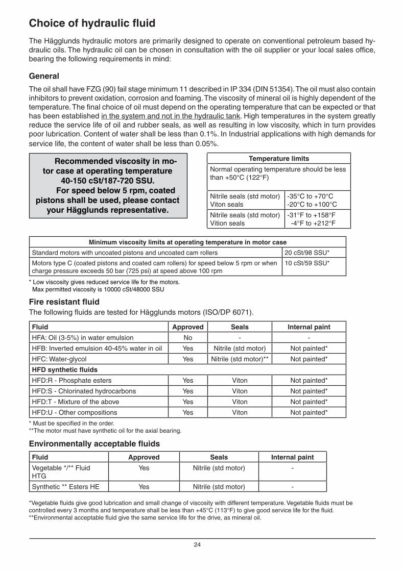
Choice of hydraulic fluid
The Hägglunds hydraulic motors are primarily designed to operate on conventional petroleum based hy-draulic oils. The hydraulic oil can be chosen in consultation with the oil supplier or your local sales office, bearing the following requirements in mind:
General
The oil shall have FZG (90) fail stage minimum 11 described in IP 334 (DIN 51354). The oil must also contain inhibitors to prevent oxidation, corrosion and foaming. The viscosity of mineral oil is highly dependent of the temperature. The final choice of oil must depend on the operating temperature that can be expected or that has been established in the system and not in the hydraulic tank. High temperatures in the system greatly reduce the service life of oil and rubber seals, as well as resulting in low viscosity, which in turn provides poor lubrication. Content of water shall be less than 0.1%. In Industrial applications with high demands for service life, the content of water shall be less than 0.05%.
Fire resistant fluidThe following fluids are tested for Hägglunds motors (ISO/DP 6071).
*Vegetable fluids give good lubrication and small change of viscosity with different temperature. Vegetable fluids must be controlled every 3 months and temperature shall be less than +45°C (113°F) to give good service life for the fluid.**Environmental acceptable fluid give the same service life for the drive, as mineral oil.
Environmentally acceptable fluids
Temperature limits
Normal operating temperature should be less than +50°C (122°F)
Nitrile seals (std motor)Viton seals
-35°C to +70°C-20°C to +100°C
Nitrile seals (std motor)Vition seals
-31°F to +158°F -4°F to +212°F
Fluid Approved Seals Internal paint
HFA: Oil (3-5%) in water emulsion No - -
HFB: Inverted emulsion 40-45% water in oil Yes Nitrile (std motor) Not painted*
HFC: Water-glycol Yes Nitrile (std motor)** Not painted*
HFD synthetic fluids
HFD:R - Phosphate esters Yes Viton Not painted*
HFD:S - Chlorinated hydrocarbons Yes Viton Not painted*
HFD:T - Mixture of the above Yes Viton Not painted*
HFD:U - Other compositions Yes Viton Not painted*
* Must be specified in the order. **The motor must have synthetic oil for the axial bearing.
Fluid Approved Seals Internal paint
Vegetable */** Fluid HTG
Yes Nitrile (std motor) -
Synthetic ** Esters HE Yes Nitrile (std motor) -
* Low viscosity gives reduced service life for the motors. Max permitted viscosity is 10000 cSt/48000 SSU
Recommended viscosity in mo-tor case at operating temperature
40-150 cSt/187-720 SSU.For speed below 5 rpm, coated
pistons shall be used, please contact your Hägglunds representative.
Minimum viscosity limits at operating temperature in motor case
Standard motors with uncoated pistons and uncoated cam rollers 20 cSt/98 SSU*
Motors type C (coated pistons and coated cam rollers) for speed below 5 rpm or when charge pressure exceeds 50 bar (725 psi) at speed above 100 rpm
10 cSt/59 SSU*

25
Choice of hydraulic fluid
Down rating of pressure, for motors used in systems with fire resistant fluids, the maximum pressure for motor given on data sheet must be multiplied with following factors:HFA-fluid not fit for useHFB-fluid 0.7 x maximum pressure for motorHFC-fluid 0.7 x maximum pressure for motorHFD-fluid 0.9 x maximum pressure for motor
Down rating of basic rating life, for motors used in systems with fire resistant fluids, the "expected basic rated life" must be multiplied with following factors:
HFA-fluid not fit for useHFB-fluid 0.26 x expected life with mineral oilHFC-fluid 0.24 x expected life with mineral oilHFD-fluid 0.80 x expected life with mineral oil
Down rating of pressure data and basic rating life
The oil in a hydraulic system must always be filtered and also new oil from your supplier has to be filtered when adding it to the system. The grade of filtration in a hydraulic system is a question of service life v.s. money spent on filtration.In order to obtain stated service life it is important to follow our recommendations concerning contamina-tion level.When choosing the filter it is important to consider the amount of dirt particles that the filter can absorb and still operate satisfactory. For that reason we recommend a filter with an indicator that gives a signal when it is time to change the filter cartridge.
Filtering recommendations
Before start-up, check that the system is thoroughly cleaned. 1. In general the contamination level should not exceed ISO 4406:1999 18/16/13 (NAS 1638, class 7).2. When filling the tank and motor case, we recommend the use of a filter with the grade of filtration ß10=75.
Filtration
Explanation of "Grade of Filtration"
Grade of filtration β10=75 indicates the following:β10 means the size of particle ≥10µm that will be removed by filtration.=75 means the grade of filtration of above mentioned size of particle. The grade of filtration is defined as number of particles in the oil before filtration in relation to number of particles in the oil after filtration.
Ex. Grade of filtration is β10=75.Before the filtration the oil contains N number of particles ≥10µm and after passing the filter once the oil
contains number of particles ≥10µm.
This means that number of particles have been filtered (=98.6%).
N75
=74·N75
N75N

26
Noise from a complete installation
A-weighted emission sound pressure level of Compact CA The emission sound pressure level have been calculated according to ISO/DIS 11203 for unattended machines. All values refer to a position of the test object > 1 m (3.28 ft).
A-weighted sound power level of Compact CAThe sound power level have been calculated according to ISO/DIS 11203 for unattended machines. All values refer to a position of the test object > 1 m (3.28 ft).
A-w
eigh
ted
emis
sion
sou
nd p
ress
ure
leve
l, dB
A-w
eigh
ted
emis
sion
sou
nd p
ress
ure
leve
l, dB
CA 50 - 70 CA 100 - 210
A-w
eigh
ted
soun
d po
wer
leve
l, B
A-w
eigh
ted
soun
d po
wer
leve
l, B
CA 50 - 70 CA 100 - 210
Background noise
Pump motor
Pipe noise
Hydraulic motor
Noise from driven unit
Foundation and construction noise
4
5
6
7
8
9
10
11
10 100 10006
7
8
9
10
11
12
10 100 1000
40
50
60
70
80
90
10 100 1000
60
70
80
90
100
10 100 1000
300 bar (4350 psi)
300 bar (4350 psi)
200 bar (2900 psi)
100 bar (1450 psi)
500 bar (725 psi)200 bar (2900 psi)100 bar (1450 psi)
50 bar (725 psi)
50 bar (725 psi)
100 bar (1450 psi)
200 bar (2900 psi)
200 bar (2900 psi)
100 bar (1450 psi)
50 bar (725 psi)

27
Declaration of Incorporation
Example of the Incorporation of Conformity given by Hägglunds Drives AB
The Declaration of Incorporation above, is available on request for deliveries from Hägglunds Drives AB. Translations into other languages are also available.
Declaration of Incorporation of partly completed machinery As defi ned by the EC Machinery Directive 2006/42/EC, Appendix II B
The manufacturer
Hägglunds Drives AB
hereby declares that the partly completed machinery
The partly completed machinery may only be put into operation when it has been established that the machine into which the partly completed machinery is to be incorporated conforms to the provisions of EC Machinery Directive 2006/42/EC, where relevant according to this directive.
The requirements are fulfi lled provided that the data in the product documentation (fi tting instructions, operat-ing instructions, project management and confi guration documents) are implemented by the product user. The requirements of Appendix I to Machinery Directive 2006/42/EC not mentioned here are not applied and have no relevance for the product.
The individual below is authorized to compile the relevant technical fi les:
Name: Björn LeidelöfAddress: Hägglunds Drives AB, S-890 42 Mellansel
Mellansel, 2009-12-29
General principle no. 1.
1.1.3 1.1.5 1.3.1 1.3.2 1.3.3 1.3.4 1.3.6 1.3.7 1.5.3 1.5.4
1.5.5 1.5.6 1.5.8 1.5.13 1.6.1 1.6.3 1.7.3 1.7.4
Name: Compact CAFunction: Hydraulic motor Model: Compact Type: CATrade name: Compact CA
satisfi es the following essential requirements of Machinery Directive 2006/42/EC in accordance with the chapter numbers in Appendix I:
It is also declared that the special technical documents for this partly completed machinery have been compiled in accordance with Appendix VII, Part B. These are trans-ferred on request to the market surveillance body in paper-based/electronic format.
Conformity with the provisions of further EU Directives, Standards or Specifi cations:
SS-EN 982SS-EN ISO 12100-1SS-EN ISO 12100-2
We reserve the right to make changes to the content of the Declaration of Incorporation. Current issue on request.


EN
396
-10H
. Rep
ro: Ö
viks
Rep
ro. P
rinte
r: Å
gren
s T
ryck
eri 2
011.
ww
w.hagglunds.com
Hägglunds Drives ABSE-890 42 Mellansel, SwedenTel: + 46 (0)660 870 00. E-mail: [email protected]
Our drive is your performance.