thorlabs.com - high-power plasma light sources
TRANSCRIPT

HIGH- POWER PLASMA LIGHT SOURCES
Hide Overview
Click to EnlargeA hyperspectral imaging system built using Thorlabs' Cerna®Microscopy Platform, KURIOS-VB1 Tunable Bandpass Filter,and HPLS343 High-Power Plasma Light Source. For details,
please see the Hyperspectral Imaging tab.
Features
Output Spectrum: 350 nm to 800 nmFree-Space Output or Output Coupled to Liquid Light Guide
Integrated and User-Replaceable Luxim® Light Emitting Plasma™ Bulb Modulewith Lifetime* 6000 hours (Typ.)Variable Attenuator Continuously Tunes Optical Output IntensityIndependent Shutter Toggled via Automated and/or Manual ControlsThree Operation Modes:
Open Loop is Default and Drives the Bulb Module with Constant Current NearRated MaximumClosed Loop Varies the Current to Stabilize Bulb's Optical Output Power at80% of Open Loop Mode PowerECO Mode Varies the Current to Stabilize Bulb's Optical Output Power at 50%of Open Loop Mode Power
HPLS343 and HPLS345 Light Sources Include Liquid Light Guide (LLG)Tip of LLG is Cooled Using Thermoelectric Coolers (TECs) to ExtendLLG's LifetimeØ3 mm (Ø5 mm) Core LLG Included with HPLS343 (HPLS345)
Downloadable Software Enables PC Control via USB and Access to Additional Control FeaturesConnectors on Back Panel Enable External Control of Key Functions Using CMOS and Analog Voltage Signals
O V E R V I E W
Broad UV to NIR Output Spectrum: 350 to 800 nmVersions Available with Free-Space or Liquid Light Guide OutputTypical Lifetime of User-Replaceable Bulb Module is 6000 hoursTypical Optical Output Power Stability of 0.5%
► ► ► ►
LLG03-4HØ3 mm Liquid Light Guide(Available Separately)
HPLS343High-Power PlasmaLight Source(Includes LiquidLight Guide)
HPLS301Free-Space, High-Power
Plasma Light Source
HPLSBReplacement BulbModule

Hide Specs
Thorlabs' high-power light sources are convenient and configurable illumination systems built around the long-lived and user-replaceable Luxim® Light EmittingPlasma (LEP)™ bulb module. These light sources are designed for long-term operation, and their optical output power is typically stable to 0.5%. Versions areavailable with a free-space output or with the light coupled into a liquid light guide (LLG), which homogenizes the transmitted bulb emission and producesa uniform output light field. The broadband wavelength spectrum extends down to 350 nm and overlaps with the common DAPI, FITC, and TRITC filter setsused in biological imaging, which makes these sources well suited for fluorescence microscopy. In addition, the wide spectrum of these sources is important forhyperspectral imaging, as explained in the Hyperspectral Imaging tab, endoscopy, and other lighting and inspection applications.
Optical Output IntensityThe transmitted intensity can be continuously controlled by turning a knob on the front panel, through software control, or by sending 0 V to 5 V signals to theconnectors on the back panel when External control is engaged. Please see the Operation tab for more information. Adjusting the transmitted optical outputintensity rotates an attenuation disk positioned between the bulb and the output. Being able to change the output intensity without changing the current drivingthe bulb module enables consistently stable optical output from the source. The intensity may be adjusted independently of the shutter control.
Front Panel DisplayThe front panel LCD shows bright text on a dark background, which is ideal for use in dim environments and is visible from across the room and at obliqueangles. The displayed information includes the percentage of the available optical power coupled into the output port, the shutter state, and an estimate of theremaining bulb module lifetime in hours.
*Long Life Bulb Module: 6000 hoursDue to the unique electrode-less design of the LEP bulb module (see the LEP™ Bulb Module tab), the lifetime of this bulb module is approximately 6 timesthat of a xenon bulb. The LEP bulb module ages gradually during operation when the source is operated in Open Loop mode, but when it operated in ClosedLoop or Eco modes the effects of aging (decreasing optical power produced for a given driving current) are not observed until closer to the end of the bulbmodule's life (see the Operation tab). When the optical output power drops to 50% of the original power, which typically occurs after 6000 hours, the bulbmodule is considered to be at its end of life. However, it is not necessary to replace the bulb module until its output power can no longer fulfill the needs ofyour application. Replacement bulb modules are available below.
Liquid Light GuidesThe HPLS343 and HPLS345 are designed to couple light from the bulb into a LLG with a Ø3 mm or Ø5 mm core, respectively. The advantages of LLGsinclude a transmitted beam free of dead spots, flexibility that allows them to be coiled, a large core size, and a high numerical aperture. Please see the LLGstab for additional information. The Ø3 mm light guide provides a beam with higher brightness, while higher total power is coupled into the Ø5 mm LLG. It ispossible to focus the beam from the Ø3 mm guide into a smaller spot, and under certain conditions this smaller core diameter may result in more power beingcoupled into a microscope. Coupling light from the endface of the LLG to a variety of microscopes can be enabled by using the collimation adapters availablebelow. Thorlabs also offers LLG-to-SM1 adapters for both Ø3 mm and Ø5 mm core LLGs (Item #s AD3LLG and AD5LLG).
These light sources use thermoelectric coolers to control the temperature of the LLG tip closest to the bulb, which extends the lifetime of the LLG. Closing theshutter during periods when the output emission of the light source is not needed will also extend the lifetime of the LLG, because this reduces its exposure tothe UV radiation from the bulb. Accumulated exposure to the UV portion of the bulb's spectrum increases the attenuation of the LLG, and the LLG should bereplaced when transmission levels drop below those required by the application. We recommend the LLGs offered below, which differ from our standard LLGofferings only in that these have a yellow band that acts as a visual guide that indicates when the LLG is correctly installed in the LLG Port of the light source.
Item # HPLS301 HPLS301/M HPLS343 HPLS345
Performance
Wavelength Range 350 nm to 800 nm
Output Free Space, Ø50 mm Liquid Light Guide
Optical Output Power9.5 Wa (Typ.)
8.5 Wa (Min)
4.0 Wb (Typ.)
3.5 Wb (Min)
7.0 Wb (Typ.)
6.0 Wb (Min)
Ouput Power Drift (Typ.)0.2%/°C0.03%/h
0.2%/°C c
0.05%/hc
Output Power Stabilityd 0.5% (Typ.)0.6% (Max)
Transmitted Intensity, Range Tunable byAttenuator
1.5% to 100% 0.1% to 100%
S P E C S

Output Intensity Non-Linearity <2%
Intensity Switch Time <3 s (10% to 90% Intensity)
Shutter States Open, Closed (Independent of Intensity Setting)
Shutter Switch Time 5 ms
Shutter Repetition Rate (Max)1 Hz (Extended Duration)
10 Hz (Burst)
Bulb Module Life Timee 6000 h (Typ.)
Correlated Color Temperature (CCT) 6000 K 6000 Kf
Color Rendering Index (CRI) 94 94f
Beam Divergence (FWHM) 6° -
Liquid Light Guide
Core Diameter - 3 mm 5 mm
Numerical Aperture (NA) - 0.59
Length - 4' (1.2 m)
Operating Wavelength Range - 340 nm to 800 nm
Communications
Baud Rate 115.2 kbps
Data Length (1 Stop Bit, No Parity, No FlowControl)
8 Bit
Command (=) and Query (?) FormatsKeyword=Argument (Carriage Return)
Keyword? (Carriage Return)
Trigger IN, Trigger OUT, and External ShutterControl
5 V CMOS
Analog IN and Analog OUT(Output Intensity)
0 V to 5 V Analog (20 kΩ Impedance)
Connectors on Back Panel BNC Female, SMA Female, USB Type Bg
Electrical
Power Supply 90 VAC to 264 VAC, 325 VA (47 Hz to 63 Hz)
Fuse 5A, 250 VAC, Type T, Slow Blow
Physical
Dimensions (Length x Width x Height)13.68" x 7.40" x 7.87"h
(347.5 mm x 188.0 mm x 200.0 mmh)
14.23" x 7.40" x 7.87"i
(361.5 mm x 188.0 mm x 200.0 mmi)
Mechanical Drawings
Output Beam Height148 mm Including Feet138 mm Excluding Feet
-
Operating Temperature Rangej,k 10 °C to 30 °C (Open and Closed Loop Mode)10 °C to 35 °C (Eco Mode)
Storage Temperature Rangek -15 °C to 70 °C
Power is measured after the free-space output, when the bulb is at start-of-life.Power is measured at the output of the liquid light guide, when bulb and LLG are at start-of-life. This value includes the photo-induced darkening of the liquid in the LLG that occurs naturally during operation as a result ofexposure to UV radiation. Typical standard deviation for measurements taken over an hour at the output of the unit.Typical value, defined as the total operation time before the maximum optical output power of the bulb reaches 50% ofits original output.Prior to LLGUSB Functions as a Virtual COM Port; 2 Meter Cable Included.The height dimension includes the feet.The height dimension includes the feet, when they are folded closed.Assumes Long-Term OperationNon-Condensing Conditions

Hide Front & Back Panels
Click to EnlargeClick Here for Raw Data
Click to EnlargeClick Here for Raw Data
The Optical Spectrum Measured at the Output of theLLG
Front Panel
Click to EnlargeHPLS Series Free-Space, Plasma Light Source Front Panel
Back Panel
Click to EnlargeHPLS Series Free-Space, Plasma Light Source Back Panel
Callout Description
F1 External Control Button with Integrated LED State Indicator
F2 Liquid Crystal Display Screen (Bright Text on Dark Field)
F3 Shutter Control Button
F4 Light Intensity Adjustment Knob
F5 Light Output Port
F6 4-40 Tapped Hole for 60 mm Cage System (4 Places)
F7 Shutter State LED Indicator
F8 Light Source State LED Indicator
F9 Power Switch
Callout Description
B1 External Shutter Control, BNC Female Port, 5 V CMOS
B2 Trigger OUT, SMA Female Port, 5 V CMOS
HPLS301(/M) Front and Back Panels
F R O N T & B A C K P A N E L S

B3 Analog IN, BNC Female Port, 0 to 5 V
B4 Trigger IN, BNC Female Port, 5 V CMOS
B5 Analog OUT, SMA Female Port, 0 to 5 V
B6 USB Type B Port
B7 AC Power Plug Port
B8 Fuse Drawer
See the Pin Diagrams tab for pin assignments.
Front Panel
Click to EnlargeHPLS Series High-Power Plasma Light Source with LLG
Front Panel
Back Panel
Click to EnlargeHPLS Series High-Power Plasma Light Source with LLG
Back Panel
Callout Description
F1 External Control Button with Integrated LED State Indicator
F2 Liquid Crystal Display Screen (Bright Text on Dark Field)
F3 Shutter Control Button
F4 Light Intensity Adjustment Knob
F5 Liquid Light Guide Port
F6 Liquid Light Guide Release Switch
F7 Shutter State LED Indicator
F8 Light Source State LED Indicator
F9 Power Switch
Callout Description
B1 External Shutter Control, BNC Female Port, 5 V CMOS
B2 Trigger OUT, SMA Female Port, 5 V CMOS
B3 Analog IN, BNC Female Port, 0 to 5 V
B4 Trigger IN, BNC Female Port, 5 V CMOS
B5 Analog OUT, SMA Female Port, 0 to 5 V
B6 USB Type B Port
B7 AC Power Plug Port
B8 Fuse Drawer
See the Pin Diagrams tab for pin assignments.
Trigger IN(Enables Intensity Output
Change)
Analog IN(Specify Intensity Output Level)
HPLS343 and HPLS345 Front and Back Panels
HPLS301(/M), HPLS343, and HPLS345 Pin Diagrams
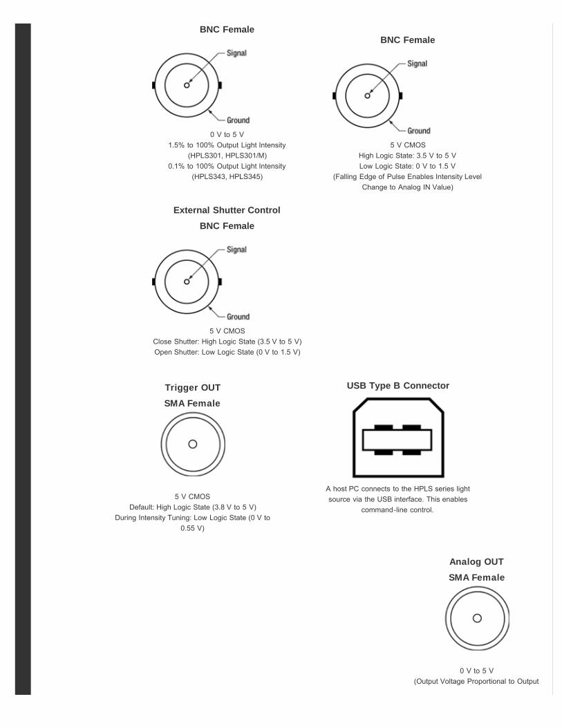
BNC Female
5 V CMOSHigh Logic State: 3.5 V to 5 VLow Logic State: 0 V to 1.5 V
(Falling Edge of Pulse Enables Intensity LevelChange to Analog IN Value)
BNC Female
0 V to 5 V1.5% to 100% Output Light Intensity
(HPLS301, HPLS301/M)0.1% to 100% Output Light Intensity
(HPLS343, HPLS345)
External Shutter ControlBNC Female
5 V CMOSClose Shutter: High Logic State (3.5 V to 5 V)Open Shutter: Low Logic State (0 V to 1.5 V)
USB Type B Connector
A host PC connects to the HPLS series lightsource via the USB interface. This enables
command-line control.
Trigger OUTSMA Female
5 V CMOSDefault: High Logic State (3.8 V to 5 V)
During Intensity Tuning: Low Logic State (0 V to0.55 V)
Analog OUTSMA Female
0 V to 5 V(Output Voltage Proportional to Output

Hide Operation
Light Intensty Percentage of Maximum)
For more information about the functions of the Analog IN, Trigger IN, Analog OUT, and Trigger OUT and the external controlof the HPLS series high-power plasma light sources, please see the Operation tab. Information about the command-line
language and using a host PC to control the HPLS sources can be found in Chapter 8 of the manuals and in the Software tab.
Click to EnlargeFigure 1: The HPLS series light sources are calibratedto give a linear ratio between the intensity setting and
the transmitted optical power. The red curve is anexample of the typical error that exists between the
calculated and measured output powers. Foradditional details, please see the text.
Click on the following links to move to the different sections in this discussion.
Output Intensity and Shutter ControlSoftware Control via a Host PCInformation Shown on LCD Screen During OperationOperational Modes: Open Loop, Closed Loop, and EcoExternal Control via Back Panel Ports
Output Intensity and Shutter ControlOutput Intensity Control: Rotate the Light Intensity Control Knob on the Front Panel to continuouslyvary the intensity of light transmitted through the output. Output intensity control operatesindependently of the shutter, and control of the intensity setting using the tuning knob and softwaremay be performed regardless of whether the shutter is open or closed.
When a host PC is interfaced with the HPLS series light sources, the operator can also use thesoftware to specify an intensity value as a percentage of the maximum possible optical output power.While operating the light source under External control, the intensity can be changed by sending theappropriate voltage signals to BNC ports on the instrument's back panel. When External control isenabled, the intensity tuning knob on the front panel is disabled. More information about Externalcontrol and software control is included in Sections 5.5 and Chapter 7, respectively, of the manual.
Adjusting the output intensity does not affect the amount of optical power emitted by the bulb; thecurrent driving the bulb is not affected by the intensity adjustment. Instead, the intensity adjustmentcontrols the rotation angle of an attenuation disk placed between the bulb and the output. The disk has an aperture that varies with rotation angle, andadjustments to intensity cause the disk to rotate so that the desired amount of optical power is transmitted through the disk.
Using an attenuation disk to adjust the transmitted intensity, rather than performing this function by changing the current levels driving the bulb module,maintains the bulb in a stable operating state while also enabling the intensity to be quickly tuned; less than 3 seconds are required to adjust the outputintensity between 90% and 10%.
The output powers of these high-power plasma light sources are calibrated so that the output power is a linear function of the intensity setting, as is illustratedby the blue curve in Figure 1. The intensity setting is reported as a percentage in the upper left corner of the display screen on the front panel, and its value isindependent of the power emitted by the bulb. The red curve in Figure 1 is an example of the typical error between the measured power after the output andthe predicted value of the output power calculated from the intensity setting and the calibration data. Each point on the error curve represents an average of100 measurements. For optimum stability, allow these light sources to warm up for between 45 minutes and an hour before use.
Shutter Control: The shutter state can be toggled between open and closed by pressing the rectangular button beside the Light Intensity Control Knob, bysending the appropriate command to the light source when it is being controlled by a host PC, or by sending a 5 V CMOS signal to the Shutter Control femaleBNC port on the back panel when external control is enabled. The shutter is closed by default, and the state of the shutter (Open/Closed) is displayed in thelower left corner of the front panel's display screen. When the shutter is open, the LED indicator to the right of the shutter control button is illuminated. Theshutter button is always operational, but pressing it while the light source is operating under external control will disable external control of the light source.
The shutter may be repetitively toggled between states with a repetition rate of up to 1 Hz for an indefinite duration, and its state may be toggled at rates up to10 Hz during bursts of a few minutes at most. If the shutter state is toggled at rates in excess of 1 Hz for longer than a few minutes, the heat generated by
O P E R A T I O N

Click to Enlarge Figure 2: Open Loop Mode: Example of
LCD Screen
Click to Enlarge Figure 3: Closed Loop Mode: Example
LCD Screen
this activity can cause the shutter to fail.
For HPLS343 and HPLS345 only: closing the shutter during periods when the output emission of the light source is not needed will extend the lifetime of theLLG. Exposure to the UV portion of the spectrum produced by these high-power light sources causes the transmissive properties of LLGs to gradually
degrade, and closing the shutter blocks the coupling of the Luxim® LEP™ bulb's light into the LLG.
Software Control via a Host PCFor greater control of the light source and more configuration options than are offered by the front panel interface, the HPLS series can be controlled by a hostPC. A software package is available for download that includes drivers and installs a GUI. Control of the light source may be performed using the GUI or byrunning custom user-written programs. Please see the Software tab for more information. Prior to running a custom program via the command-line interface,install the drivers included in the software download, power on the light source, and connect a USB cable between the PC and the light source. The GUI andcommand line language, listed and described in Chapter 7 of the manuals, allow the user to:
Obtain Various Status and Instrument Identification InformationTurn the Bulb On and OffSet the Output Intensity Optical PowerSet the Shutter StateSet the Operation Mode: Open Loop, Closed Loop, and Closed Loop Eco ModesToggle Between External (Voltage Signals Sent to Back Panel Connectors) and Local (Front Panel and PC) Operation
Information Shown on LCD Screen During OperationThe Liquid Crystal Display (LCD) screen features bright text on a dark background, and the text remains visiblefrom across the room and at oblique angles. The dark background emits less light into the room than do displaysfeaturing dark text on a bright background, which makes it less disruptive under dim lighting conditions. Thedisplay, an example of which is shown in Figure 2, has five different fields:
Upper Left Corner : The transmitted light intensity, which is controlled by tuning the attenuator positionedbetween the bulb and the output, is shown.Upper Right Corner : MANUAL indicates front panel and PC control, and EXTERNAL indicates control via back panel connectors is enabled.Lower Right Corner : The current state of the device is shown.Lower Left Corner : The shutter state, which is either Open or Close, is displayed.Center: When operating in Open Loop Mode, nothing is displayed in the center (see the image at the right). The letter "C" is displayed when operatingin Closed Loop Mode, and the letter "E" is displayed when operating in Eco Mode. Information about the different operating modes and examples ofthe Closed Loop and Eco display screens are shown in Figures 4 and 5, respectively.
Operation Modes: Open Loop, Closed Loop, and Closed Loop EcoThe HPLS series light sources feature three different operation modes: Open Loop, Closed Loop, and Closed Loop Eco. When the operating mode is changed,the driving current sent to the bulb is affected. This is in contrast to using the front panel knob, software, or back panel connection controls to adjust theintensity, which changes the coupling ratio between the bulb and the liquid light guide but does not affect the current driving the bulb.
The default operation mode, which is set at the factory, is Open Loop mode. When a PC is interfaced with the light source, the operation mode can bechanged using the GUI or command-line interface. It is not possible to change the operation mode via interaction with the front panel or when external controlis enabled. Changing the operation mode updates the operation mode setting stored in non-volatile memory. When the light source is powered on, the activeoperation mode is the one that was active when the source was last powered down.
Open Loop Mode: This is the default operation mode, which is set at the factory and produces the highest optical output power from the bulb. In this mode,the current driving the lamp is held constant near the current limit. As the optical output intensity of the bulb is not stabilized, this intensity can be expected toslowly vary during short-term operation. Over longer durations, the output intensity of the bulb will gradually decrease as the bulb ages. Figure 2 shows anexample of the display screen corresponding to operation in Open Loop Mode.
Closed Loop Mode: In Closed Loop mode, the optical output power of the bulb is stabilized at a target level usinga feedback mechanism. An initialization process that occurs at start-up determines the target intensity. Duringinitialization, the bulb is driven at a constant current level of approximately 90% of the current limit. A photodiodelocated near the bulb measures the optical output intensity, and then the target optical output power level for thismode is set to be 80% of this measured value. During operation, this optical output power is maintained by using afeedback mechanism to adjust the bulb's driving current as appropriate. Closed Loop mode operation provides amore stable output intensity than Open Loop mode, and it also compensates for the gradual decrease in thelamp's optical output power that occurs as the bulb ages. The letter "C" in the top-center of the LCD display shownin Figure 3 indicates the light source is operating in Closed Loop mode.

Hide LEP Bulb Module
Click to Enlarge Figure 4: Eco Mode: Example LCD
ScreenEco Mode: This mode operates similarly to Closed Loop mode, with the difference being that Eco mode stabilizesthe optical output power at a lower intensity. Rather than stabilize the optical output power of the bulb at 80% ofthe Open Loop mode power, as is done in Closed Loop mode, Eco mode stabilizes the optical output power of the bulb at 50% of the Open Loop modepower. A benefit of operating at this lower power level is that the bulb suffers less heat stress than it does when operating in the standard Closed Loop mode,and this is expected to extend the lifetime of the bulb. As is true when operating in the standard Closed Loop mode, Eco mode compensates for both transientvariations in the optical output power of the bulb and the gradual decrease in the lamp's optical output power. The letter "E" in the top-center of the LCDdisplay shown in Figure 4 indicates the light source is operating in Eco mode.
Click on the More [+] link below to view plots illustrating the effects of the operating mode and liquid light guide (HPLS343 and HPLS345 only) on the intensityof the transmitted light. Data were acquired over a continuous 48 hour period, and measurements were recorded both just before the input and at the outputof the LLG (HPLS343 and HPLS345), or after the free-space output (HPLS301). Results are plotted for Open Loop and Closed Loop modes, with the ClosedLoop mode data also applying to Eco mode.
The measurements taken at the input of the LLG and for the free-space version describe time-dependent bulb intensity independent of other effects. Themeasurements taken at the output of the LLG include the optical transmission characteristics of the LLG. As is discussed in the LLGs tab, LLGs act tohomogenize the light transmitted through them, which smooths the time-dependent intensity data curves. In addition, the light transmission levels throughLLGs decrease with time in response to exposure to UV radiation. While operation in Closed Loop or Eco modes maintains the optical output power of thebulb at the target level, these modes do not compensate for the attenuation of the transmitted light through the LLG that increases with time as a result of theaging of the liquid in the guide.
Graphs of Optical Intensity, Open and Closed Loop Operation, 48 Hour Duration
External Control via Back Panel BNC and SMA ConnectionsExternal control of the light source is enabled by pressing the button labeled "External," which is located above the LCD display on the front panel of theinstrument. After the button is pressed, it illuminates and stays illuminated while External mode is active. Enabling External control disables both software (PC)and front panel control, with the exception of the shutter. Both the shutter button on the front panel and software control of the shutter remain active for safetyreasons; however, using one of these methods to toggle the shutter will automatically disable External control and return the instrument to Local control, inwhich the front panel and PC control are active.
External control of the light sources is performed by sending signals to a trio of female BNC connectors of the back panel of the instrument (Shutter Control,Analog IN and Trigger IN). The back panel also includes a pair of female SMA output connectors that provide access to status information (Analog OUT andTrigger OUT). Please see the Front & Back Panels tab for information about the Back Panel connectors.
Click to EnlargeDiagram of the LEP Bulb Module
Architecture
The user-replaceable Luxim® Light Emitting Plasma (LEP)™ bulb module at the core of the high-power light sources is anintense source of full-spectrum white light and has a typical lifetime of 6000 hours. A major contributing factor to its long life,which is six times that of a xenon bulb, is a design that includes no electrodes and is strikingly different than the design ofmetal-halide discharge lamps and other conventional light sources.
The sketch in Figure 1 depicts the architecture of the LEP bulb module. Contained within the ceramic resonator are twoantennas, and the sealed quartz bulb is positioned at the center. The bulb contains a small amount of a halide salt mixtureas well as inert and other gasses. The radio frequency (RF) driver is connected to the power input and feedback antennasusing low-loss coaxial cables. When operating, the electric circuit generates an RF field, which is amplified and concentrated by the structure of the ceramicresonator. The bulb position coincides with the most intense region of the RF field, and the energy of the field ionizes the gasses and vaporizes the halidescontained in the quartz bulb. The ionized gases transfer energy to the metal halide salts, which form an intense plasma column at the center of the bulb. Thisis the highly-efficient source of the intense full-spectrum white light. A reflective material located at the back of the lamp is used to direct all generated lightinto the forward direction.
In conventional metal-halide discharge lamp designs, a plasma is formed inside the bulb by transmitting a high-energy pulse across the two electrodes. Each
L E P B U L B M O D U L E
Hide LLGs
pulse not only creates a plasma in the bulb but also vaporizes some of the electrode material, which both erodes the electrodes and deposits a metal on thebulb. This degrades the performance of the lamp and leads to its failure. In addition, the electrodes act as heat sinks that draw power away from the bulb. Thedriving energy applied to the bulb must be high enough to overcome these losses.
The LEP bulb module, by energizing a plasma arc without using filaments or electrodes, eliminates all failure modes and inefficiencies of traditional broadbandlight sources, which results in an incredibly bright and stable source with long life span comparable only to light emitting diodes (LEDs).
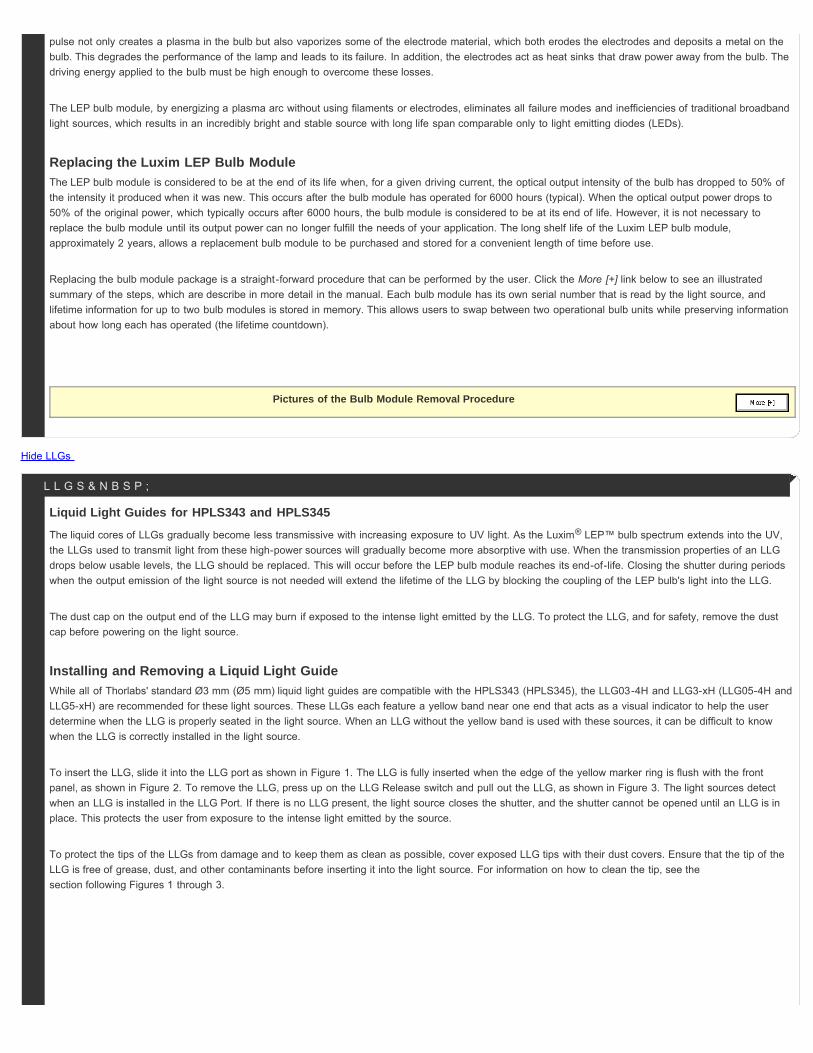
Replacing the Luxim LEP Bulb ModuleThe LEP bulb module is considered to be at the end of its life when, for a given driving current, the optical output intensity of the bulb has dropped to 50% ofthe intensity it produced when it was new. This occurs after the bulb module has operated for 6000 hours (typical). When the optical output power drops to50% of the original power, which typically occurs after 6000 hours, the bulb module is considered to be at its end of life. However, it is not necessary toreplace the bulb module until its output power can no longer fulfill the needs of your application. The long shelf life of the Luxim LEP bulb module,approximately 2 years, allows a replacement bulb module to be purchased and stored for a convenient length of time before use.
Replacing the bulb module package is a straight-forward procedure that can be performed by the user. Click the More [+] link below to see an illustratedsummary of the steps, which are describe in more detail in the manual. Each bulb module has its own serial number that is read by the light source, andlifetime information for up to two bulb modules is stored in memory. This allows users to swap between two operational bulb units while preserving informationabout how long each has operated (the lifetime countdown).
Pictures of the Bulb Module Removal Procedure
Liquid Light Guides for HPLS343 and HPLS345The liquid cores of LLGs gradually become less transmissive with increasing exposure to UV light. As the Luxim® LEP™ bulb spectrum extends into the UV,the LLGs used to transmit light from these high-power sources will gradually become more absorptive with use. When the transmission properties of an LLGdrops below usable levels, the LLG should be replaced. This will occur before the LEP bulb module reaches its end-of-life. Closing the shutter during periodswhen the output emission of the light source is not needed will extend the lifetime of the LLG by blocking the coupling of the LEP bulb's light into the LLG.
The dust cap on the output end of the LLG may burn if exposed to the intense light emitted by the LLG. To protect the LLG, and for safety, remove the dustcap before powering on the light source.
Installing and Removing a Liquid Light GuideWhile all of Thorlabs' standard Ø3 mm (Ø5 mm) liquid light guides are compatible with the HPLS343 (HPLS345), the LLG03-4H and LLG3-xH (LLG05-4H andLLG5-xH) are recommended for these light sources. These LLGs each feature a yellow band near one end that acts as a visual indicator to help the userdetermine when the LLG is properly seated in the light source. When an LLG without the yellow band is used with these sources, it can be difficult to knowwhen the LLG is correctly installed in the light source.
To insert the LLG, slide it into the LLG port as shown in Figure 1. The LLG is fully inserted when the edge of the yellow marker ring is flush with the frontpanel, as shown in Figure 2. To remove the LLG, press up on the LLG Release switch and pull out the LLG, as shown in Figure 3. The light sources detectwhen an LLG is installed in the LLG Port. If there is no LLG present, the light source closes the shutter, and the shutter cannot be opened until an LLG is inplace. This protects the user from exposure to the intense light emitted by the source.
To protect the tips of the LLGs from damage and to keep them as clean as possible, cover exposed LLG tips with their dust covers. Ensure that the tip of theLLG is free of grease, dust, and other contaminants before inserting it into the light source. For information on how to clean the tip, see thesection following Figures 1 through 3.
L L G S & N B S P ;

Click to Enlarge Figure 3: To remove the LLG, press up onthe Release LLG switch and pull out the LLG.
Click to Enlarge Figure 2: As shown above, the LLG is
correctly installed when the edge of the yellowband is flush with the front panel of the light
source.
Click to EnlargeFigure 1: After ensuring the tip closest to the
yellow band is clean, slide that tip into theLLG Port. Continue to push the end of the LLGinto the port until the edge of the yellow band
is flush with the front panel (Figure 2).
Click to EnlargeFigure 4: Plotted are typical transmission
data for a Ø3 mm core, 4' long LLG, with therecommended operation wavelength rangeshaded blue. As a function of length, onlyminimal variations (<2.3%) are expected
between our 4' (1.2 m), 6' (1.8 m), and 8' (2.4m) long liquid light guides.
Click to EnlargeFigure 5: Plotted are typical transmission
data for a Ø5 mm core, 4' long LLG, with therecommended operation wavelength rangeshaded blue. As a function of length, onlyminimal variations (<2.3%) are expected
between 4' (1.2 m), 6' (1.8 m), and 8' (2.4 m)long liquid light guides.
Liquid Light Guide OverviewA variety of applications benefit from the heat and vibration isolation achieved by routing the optical poweroutput by a light source from a distant location to where it is needed. The HPLS343 and HPLS345 have beendesigned to accept liquid light guides (LLGs) with Ø3 mm and Ø5 mm cores, respectively. LLGs are flexiblelight pipes fabricated from a polymer tube filled with a transparent, non-toxic, and non-flammable liquid. Thetips of the tube are sealed with fused silica caps, which also act as optical end faces. Transmission throughthe LLG homogenizes the light field across the diameter of the core, which produces an output beam withuniform intensity. The many advantages of pairing an LLG with a high-power and broadband light sourceinclude:
A Homogenous Transmitted Beam Free of the Dead Spots that Characterize the Light Field from aSilica Fiber BundleThe Ability to Coil and Arrange the LLGs, in Contrast to Silica Rods of Comparable Diameters thatBreak if BentThe Large Core Size and High Numerical Aperture of the LLGExcellent Transmission over the Entire Visible Spectral Range (Figures 4 and 5)
When used with the HPLS343 and HPLS345 light sources, the gasket of the LLG should not exceed 45 °C forlong durations and 60 °C for durations of less than an hour. The gasket is indicated by the change in thefitting from chrome metal to a black color, as shown in the figure to the lower right. These LLGs are designedto operate at temperatures between -5 °C to 35 °C. The HPLS343 and HPLS345 light sources protect theLLG against excessive temperatures by monitoring the temperature of the tip of the LLG closest to the bulb,cooling the tip as required using a combination of thermoelectric coolers and fans, and powering down thelight source if necessary. At higher temperatures, bubbles form in the liquid, which degrades the transmissionproperties of the LLG. If the temperature of gasket is between 45 °C to 60 °C for less than an hour, thebubbles can be reabsorbed by the liquid if the LLG is allowed to cool. We recommended a cool-down time ofno less than 30 minutes. If the temperature of the gasket exceeds 60 °C, the LLG can be permanentlydamaged; the bubbles in the liquid will have a severe negative impact on the transmission properties of theLLG, and these high temperatures can also cause structural damage by degrading the seals between thevarious structural components of the guide.

Hide Software
Liquid Light Guide Dimensions and Minimum Bend Radius:
Active CoreDiameter Standard End Fittings Protective Sleeve Min Bend Radius
d0 d1 l1 d2 l2 d3 -
Ø3 mm Ø5 +0/-0.1 mm 20 ± 0.1 mm Ø9 ± 0.1 mm 24 ± 0.1 mm Ø7 ± 0.1 mm 40 mm
Ø5 mm Ø7 +0/-0.1 mm 20 ± 0.1 mm Ø10 ± 0.1 mm 24 ± 0.1 mm Ø9.5 ± 0.1 mm 60 mm
The drawing and photograph below illustrate the dimensions given in the table above. 180 ± 1° indicates the flatness tolerencebetween the metal and black material in the segment labled l2.
Figure 6:Diagram of an LLG Tip, with End Face at Left
Figure 7: End portion of an LLG with Key Dimensions Labeled.
LLGs, while flexible, also posses minimum bend radii. See the table below for the minimum bend radii of these LLGs. The tubes will develop permanent kinks ifforced into a bend tighter than the minimum specification.
Reduction in Transmission with Exposure to Ultraviolet Light: The liquid in LLGs gradually becomes less transmissive with increasing exposure to UVlight. As the LEP bulb spectrum extends into the UV, the LLGs used with the HPLS sources will gradually become more absorptive with use. When thetransmission properties drop below usable levels, the LLG should be replaced.
Cleaning the Optical End Faces of Liquid Light Guides: The fused silica, PTFE, and metal (either aluminum, chrome plated brass, or stainless steel)materials composing LLGs are resistant to common cleaning solvents; however, the tips of the LLGs should not be submerged in solvent, and neithershould a heavily soaked cleaning pad be applied to the tip. Saturating the tip with solvent can result in the solvent penetrating the seal between the silica endface and the polymer tube and damaging the guide. If debris cannot be removed from the end face by wiping it with solvent, a razor blade, handled gently, canbe used to clean the tip. If a razor blade is used, ensure that it does not chip the edge of the fused silica glass end face.
Click to EnlargeThe GUI for the HPLS High-Power Plasma
Light Sources
Software for the HPLS Series High-Power Plasma Light SourcesAn external host PC can control the operation of the HPLS series high-power plasma light sources. Userscan choose to operate the source through a GUI or by writing and running custom programs. The drivers andsoftware that enable both methods of control can be downloaded by clicking on the following link. An image of theGUI is shown in the image to the right and described in Chapter 7 of the manual, while the command-linelanguage used to write custom programs is described in Chapter 8. Prior to running a custom program via thecommand-line interface, the downloadable drivers should be installed, the instrument should be powered on, anda USB cable should be connected between the host PC and the USB type B port on the back panel of the lightsource.
The basic command structure is a keyword, followed by an equals sign (=), followed by a character string, and terminated by a carriage return (CR). Anexample of a command is LAD=3 (CR), which sets the operation mode of the light source to Eco mode. The query command structure is a keyword, followedby a question mark (?), and terminated by a carriage return. An example of a query is LLG? (CR), which will return the temperature of the tip of the liquid lightguide.
S O F T W A R E
SoftwareVersion 1.4.1
FirmwareHPLS301: Version 1.2

Hide Shipping List
Hide Hyperspectral Imaging
HPLS343 & HPLS345: Version 1.4
Click to EnlargeHPLS343 and HPLS345 System Components
Items Included with Each HPLS301(/M) Plasma Light Source:
One Light Source UnitOne Region-Specific Power CordOne USB2.0 A-B Cable, 2 Meters LongOne 2 mm Hex KeyOne 3 mm Hex KeyOne Flash Drive with Software and Operation Manual
Items Included with Each HPLS343 and HPLS345 Plasma LightSource:
One Light Source UnitOne Liquid Light Guide (LLG03-4H for the HPLS343, LLG05-4H for theHPLS345)One Region-Specific Power CordOne USB2.0 A-B Cable, 2 Meters LongOne 2 mm Hex KeyOne 3 mm Hex KeyOne Flash Drive with Software and Operation Manual
S H I P P I N G L I S T & N B S P ;
Click to EnlargeSchematic of Hyperspectral Imaging
Click to EnlargeA hyperspectral imaging system built using Thorlabs'Cerna® Microscopy Platform, KURIOS-VB1 Tunable
Bandpass Filter, 1501M-GE Monochrome Scientific Camera,and the HPLS343 High-Power Plasma Light Source. Pleasecontact technical support for infomation on building this
system.
Application Idea: HyperspectralImagingIn hyperspectral imaging, a stack of spectrallyseparated, two-dimensional images is acquired. Thistechnique is frequently used in microscopy, biomedicalimaging, and machine vision, as it allows quick sampleidentification and analysis.
Hyperspectral imaging obtains images with significantlybetter spectral resolution than that provided bystandalone color cameras. Color cameras represent theentire spectral range of an image by using threerelatively wide spectral channels—red, green, and blue.In contrast, hyperspectral imaging systems incorporateoptical elements such as liquid crystal tunable bandpassfilters or diffraction gratings, which create spectralchannels with significantly narrower bandwidths.
Thorlabs' Cerna® microscopy platform, Kurios® tunable filters, and scientific-grade cameras are easily adapted to hyperspectral imaging. The Cerna platform isa modular microscopy system that integrates with Thorlabs' SM lens tube construction systems and supports transmitted light illumination. Kurios tunablefilters have SM-threaded interfaces for connections to the Cerna platform and our cameras. In addition, Kurios filters include software and a benchtopcontroller with external triggers, which enable fast, automated, synchronized wavelength switching and image capture.
Example Image StackThe data in the images and video below demonstrate the hyperspectral imaging technique. Figure 1 depicts two images of a mature capsella bursa-pastorisembryo (also known as shepherd's-purse) taken with a Kurios filter set to center wavelengths of 500 nm and 650 nm. These two images show that an entire
H Y P E R S P E C T R A L I M A G I N G

Hide Lamp Selection Guide
Click to EnlargeFigure 3: A color image of the mature capsella bursa-pastoris
embryo, assembled using the entire field of view acquired in eachspectral channel, as shown in Figure 1. By acquiring across multiple
channels, a spectrum for each pixel in the image is obtained.
Click to EnlargeFigure 1: Two images of a mature capsella bursa-pastorisembryo taken at different center wavelengths. The entire
field of view is acquired for each spectral channel.
field of view is acquired at each spectral channel. Figure 2 is a video containing 31 images of the same sample, taken at center wavelengths from 420 nm to730 nm in 10 nm steps. (10 nm is not the spectral resolution; the spectral resolution is set by the FWHM bandwidth at each wavelength.) In Figure 3, imagesfrom each spectral channel are used to determine the color of each pixel and assemble a color image. Figure 3 also demonstrates that a broadband spectrumis acquired at each pixel, permitting spectroscopic identification of different sample features within the field of view.
Kurios tunable filters offer a number of advantages for hyperspectral imaging. Unlike approaches that rely upon angle-tunable filters or manual filter swapping,Kurios filters use no moving parts, enabling vibrationless wavelength switching on millisecond timescales. Because the filter is not moved or exchanged duringthe measurement, the data is not subject to "pixel shift" image registration issues. Our filters also include software and a benchtop controller with externaltriggers, making them easy to integrate with data acquisition and analysis programs.
Below is a selection guide for all of our white-light, broadband light sources (or lamps). In addition to these sources, Thorlabs also offers unmounted white-lightLEDs, white-light mounted LEDs, white-light fiber-coupled LEDs, and high-powered, white-light Solis™ LEDs.
Broadband Light Source Selection Guide
Item #
(Click toEnlarge;Not toScale)
Emitter TypeWavelength
Range(Click for Plot)
Output CouplingOutputPower
BulbElectrical
Power
ColorTemperature
BulbLifetime
ReplacementBulb
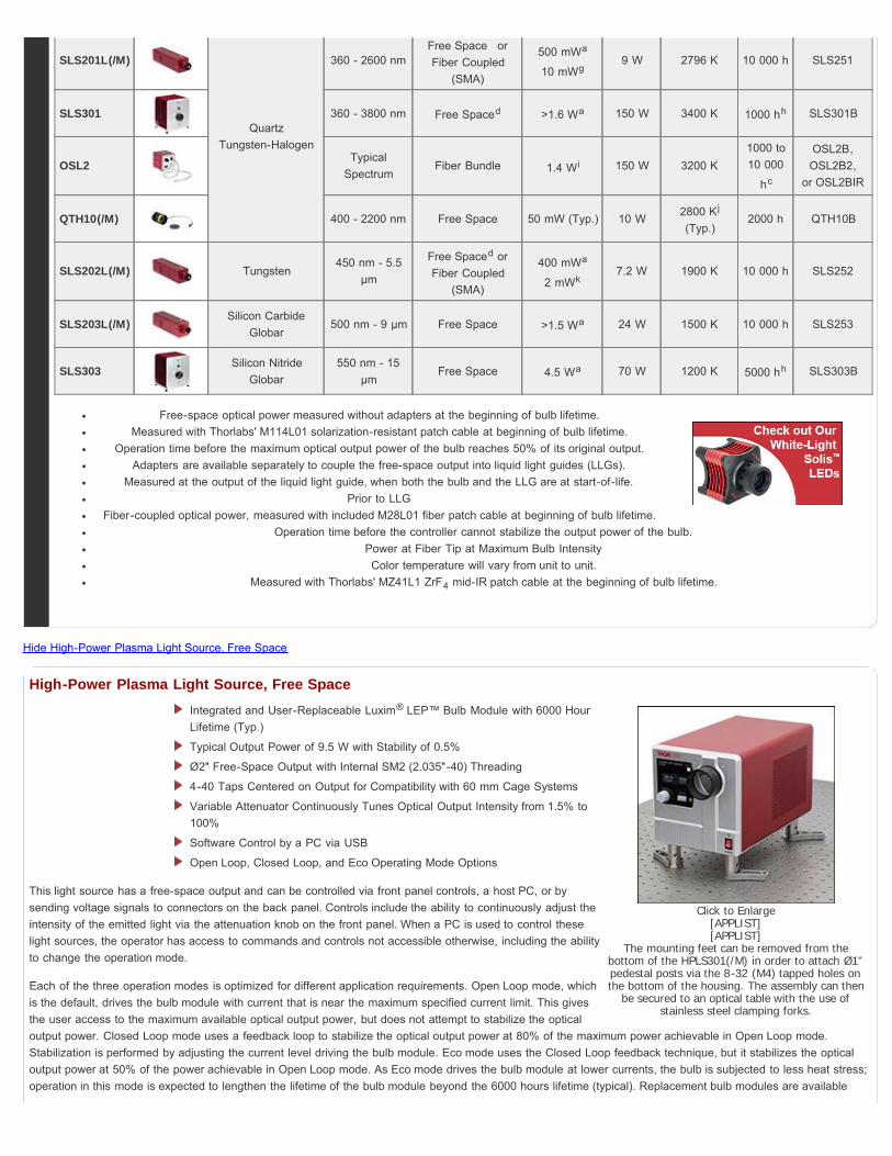
SLS204 Deuterium 200 - 700 nmFree Space orFiber Coupled
(SMA)
2 mWa
0.1 mWb
(Typ.)
30 W N/A 2000 hc SLS254B
SLS401 Xenon Arc 240 - 2400 nm Free Spaced >1.3 Wa 150 W 5800 K 2000 hc SLS401B
SLS402 Mercury-Xenon Arc 240 - 2400 nm Free Spaced >1.3 Wa 150 W 6000 K 2000 hc SLS402B
HPLS301(/M)
RF-Driven Plasma
350 - 800 nm Free Space 9.5 Wa (Typ.) - 6000 K 6000 hc HPLSB
HPLS343 350 - 800 nmØ3 mm LiquidLight Guide 4 We (Typ.) - 6000 Kf 6000 hc HPLSB
HPLS345 350 - 800 nmØ5 mm LiquidLight Guide 7 We (Typ.) - 6000 Kf 6000 hc HPLSB
d
L A M P S E L E C T I O N G U I D E
Click to Enlarge[APPLIST][APPLIST]
The mounting feet can be removed from thebottom of the HPLS301(/M) in order to attach Ø1"pedestal posts via the 8-32 (M4) tapped holes onthe bottom of the housing. The assembly can then
be secured to an optical table with the use ofstainless steel clamping forks.
Hide High-Power Plasma Light Source, Free Space
High-Power Plasma Light Source, Free SpaceIntegrated and User-Replaceable Luxim® LEP™ Bulb Module with 6000 HourLifetime (Typ.)
Typical Output Power of 9.5 W with Stability of 0.5%
Ø2" Free-Space Output with Internal SM2 (2.035"-40) Threading
4-40 Taps Centered on Output for Compatibility with 60 mm Cage Systems
Variable Attenuator Continuously Tunes Optical Output Intensity from 1.5% to100%
Software Control by a PC via USB
Open Loop, Closed Loop, and Eco Operating Mode Options
This light source has a free-space output and can be controlled via front panel controls, a host PC, or bysending voltage signals to connectors on the back panel. Controls include the ability to continuously adjust theintensity of the emitted light via the attenuation knob on the front panel. When a PC is used to control theselight sources, the operator has access to commands and controls not accessible otherwise, including the abilityto change the operation mode.
Each of the three operation modes is optimized for different application requirements. Open Loop mode, whichis the default, drives the bulb module with current that is near the maximum specified current limit. This givesthe user access to the maximum available optical output power, but does not attempt to stabilize the opticaloutput power. Closed Loop mode uses a feedback loop to stabilize the optical output power at 80% of the maximum power achievable in Open Loop mode.Stabilization is performed by adjusting the current level driving the bulb module. Eco mode uses the Closed Loop feedback technique, but it stabilizes the opticaloutput power at 50% of the power achievable in Open Loop mode. As Eco mode drives the bulb module at lower currents, the bulb is subjected to less heat stress;operation in this mode is expected to lengthen the lifetime of the bulb module beyond the 6000 hours lifetime (typical). Replacement bulb modules are available
SLS201L(/M)
QuartzTungsten-Halogen
360 - 2600 nmFree Space orFiber Coupled
(SMA)
500 mWa
10 mWg9 W 2796 K 10 000 h SLS251
SLS301 360 - 3800 nm Free Spaced >1.6 Wa 150 W 3400 K 1000 hh SLS301B
OSL2Typical
SpectrumFiber Bundle 1.4 Wi 150 W 3200 K
1000 to10 000
hc
OSL2B,OSL2B2,
or OSL2BIR
QTH10(/M) 400 - 2200 nm Free Space 50 mW (Typ.) 10 W 2800 Kj
(Typ.)2000 h QTH10B
SLS202L(/M) Tungsten450 nm - 5.5
µm
Free Spaced orFiber Coupled
(SMA)
400 mWa
2 mWk7.2 W 1900 K 10 000 h SLS252
SLS203L(/M)Silicon Carbide
Globar500 nm - 9 µm Free Space >1.5 Wa 24 W 1500 K 10 000 h SLS253
SLS303Silicon Nitride
Globar550 nm - 15
µmFree Space 4.5 Wa 70 W 1200 K 5000 hh SLS303B
Free-space optical power measured without adapters at the beginning of bulb lifetime.Measured with Thorlabs' M114L01 solarization-resistant patch cable at beginning of bulb lifetime.
Operation time before the maximum optical output power of the bulb reaches 50% of its original output.Adapters are available separately to couple the free-space output into liquid light guides (LLGs).
Measured at the output of the liquid light guide, when both the bulb and the LLG are at start-of-life.Prior to LLG
Fiber-coupled optical power, measured with included M28L01 fiber patch cable at beginning of bulb lifetime.Operation time before the controller cannot stabilize the output power of the bulb.
Power at Fiber Tip at Maximum Bulb IntensityColor temperature will vary from unit to unit.
Measured with Thorlabs' MZ41L1 ZrF4 mid-IR patch cable at the beginning of bulb lifetime.

below.
The unit comes with four rubber mounting feet. These can be removed in order to access the 8-32 (M4) mounting taps on the bottom of the housing. This allowsthe unit to be mounted on four Ø1" pedestal posts or Ø1" pillar posts.
The output port features internal SM2 (2.035"-40) threading and can be integrated with our SM2 lens tube systems. Four 4-40 tapped holes are located around theoutput for compatibility with our 60 mm cage systems. The center of the output beam is 148 mm above the table surface when the rubber feet are attached, or 138mm from the bottom of the housing.
Part Number Description Price Availability
HPLS301/M High-Power Plasma Light Source, Free-Space Output, M4 Mounting Taps $4,841.00 Today
HPLS301 High-Power Plasma Light Source, Free-Space Output, 8-32 Mounting Taps $4,841.00 Today
Hide High-Power Plasma Light Source with Liquid Light Guide
High-Power Plasma Light Source with Liquid Light GuideIntegrated and User-Replaceable Luxim® LEP™ Bulb Module with 6000 Hour Lifetime (Typ.)
Typical Output Power of 4.0 W (HPLS343) or 7.0 W (HPLS345), with Stability of 0.5%
Ø3 mm (Ø5 mm) LLG with Yellow Band Insertion Depth Indicator Included with the HPLS343 (HPLS345)
Variable Attenuator Continuously Tunes Optical Output Intensity from 0.1% to 100%
Software Control by a PC via USB
Open Loop, Closed Loop, and Eco Operating Mode Options
These sources are designed to be used with liquid light guides and can be controlled via front panel controls, a host PC, or by sending voltage signals toconnectors on the back panel. Controls include the ability to continuously adjust the amount of light coupled from the bulb into the LLG and to independently togglethe shutter state. When a PC is used to control these light sources, the operator has access to commands and controls not accessible otherwise, including theability to change the operation mode.
Each of the three operation modes is optimized for different application requirements. Open Loop mode, which is the default, drives the bulb module with currentthat is near the maximum specified current limit. This gives the user access to the maximum available optical output power, but does not attempt to stabilize theoptical output power. Closed Loop mode uses a feedback loop to stabilize the optical output power at 80% of the maximum power achievable in Open Loop mode.Stabilization is performed by adjusting the current level driving the bulb module. Eco mode uses the Closed Loop feedback technique, but it stabilizes the opticaloutput power at 50% of the power achievable in Open Loop mode. As Eco mode drives the bulb module at lower currents, the bulb is subjected to less heat stress;operation in this mode is expected to lengthen the lifetime of the bulb module beyond the 6000 hours lifetime (typical). Replacement bulb modules are availablebelow.
The dust cap on the output end of the LLG may burn if exposed to the intense light emitted by the LLG. To protect the LLG, and for safety, remove the dust capbefore powering on the light source.
Part Number Description Price Availability
HPLS343 High-Power Plasma Light Source and Ø3 mm Liquid Light Guide $5,326.54 Lead Time
HPLS345 High-Power Plasma Light Source and Ø5 mm Liquid Light Guide $5,358.06 Today
Hide Multi-Optic Collimating Microscope Adapters for Thorlabs' Cerna Microscopes
Multi-Optic Collimating Microscope Adapters for Thorlabs' Cerna Microscopes
Thorlabs offers collimation adapters to couple Ø3 mm or Ø5 mm liquid light guides (LLGs) to our CSE2100 and CSE2200 Cerna® Epi-Illuminator Modules; see thetable at the bottom right for compatibility information. For even illumination at the back focal plane of the objective, these adapters feature an optic pair of anachromatic doublet and a double convex lens.
These adapters utilize a male D3T dovetail adapter to connect to the end of the epi-illuminator module; for additional information about microscope dovetails, seethe full web presentation. The LLG is secured via a thumbscrew at the back of the adapter.
These adapters are calibrated such that the image plane from the LLG output is located at the back aperture of the objective when used with the compatible epi-illuminator module; to optimize illumination for your microscope or realign the image plane, the collimation can be fine-adjusted via the knurled ring on the threadadapter (see image to the bottom left).

Specifications
Item # LLG3A6 LLG5A6 LLG3A7 LLG5A7
Effective Focal Length 40 mm 70 mm
Compatible Epi-Illuminator Module
CSE2100 CSE2200
LLG Diameter 3 mm 5 mm 3 mm 5 mm
Collimating OpticsAchromatic Doublet & Double Convex Lens
AR Coating350 nm - 650 nm
Ravg < 0.5% at Each Surface
Transmission Graph(Click Here for Raw Data)
Numerical Aperture 0.3
Magnification Infinite
Click to EnlargeCutaway View of LLG CollimationAdapter Depicting Multi-Element
Design
Click for DetailsThese simulations illustrate chromatic focal shift in asystem with a collimated light source and a CSE2100epi-illuminator module. A collimation adapter using a
single optic (top) produces a larger focal shift fordifferent wavelengths at the objective back aperture
compared to a collimation adapter with a multi-element design (bottom).
Click to EnlargeOutput With Collimation
Adapter
Click to EnlargeOutput Without Collimation
Adapter
Click to EnlargeCollimation Adapter Fitted to the
Tip of an LLG
CompatibleMicroscopes
Olympus BX & IXMicroscopes
Leica DMIMicroscopes
Zeiss AxioskopMicroscopes
Nikon Eclipse TiMicroscopes
Item Photo(Click to Enlarge)
Item # LLG3A1-A LLG5A1-A LLG3A2-A LLG5A2-A LLG3A4-A LLG5A4-A LLG3A5-A LLG5A5-A
LLG Diameter 3 mm 5 mm 3 mm 5 mm 3 mm 5 mm 3 mm 5 mm
Optic Specifications
Item #ACL5040-A Aspheric
Condenser Lens
350 nm - 700 nm,
Part Number Description Price Availability
LLG3A6 Ø3 mm LLG Collimating Adapter for Cerna CSE2100, ARC: 350-650 nm $463.50 Today
LLG5A6 Ø5 mm LLG Collimating Adapter for Cerna CSE2100, ARC: 350-650 nm $463.50 Today
LLG3A7 Ø3 mm LLG Collimating Adapter for Cerna CSE2200, ARC: 350-650 nm $463.50 Today
LLG5A7 Ø5 mm LLG Collimating Adapter for Cerna CSE2200, ARC: 350-650 nm $463.50 Today
Hide Single-Element Collimating Microscope Adapters
Single-Element Collimating Microscope Adapters
Thorlabs offers collimation adapters with AR-coated asphericcondenser lenses (EFL = 40 mm) for collimating the output from ourHigh-Power Light Sources. Four different collimator housings areavailable; each is designed to mate to the illumination port on anOlympus IX/BX, Leica DMI, Zeiss Axioskop, or Nikon Eclipse Timicroscope.
These adapters quickly mount onto the end of either the Ø3 mm or Ø5 mm Liquid Light Guide (LLG).The LLG is secured into the back of the collimator via a 4-40 setscrew with a 0.050" hex. The additionof these adapters allows the user to incorporate our HPLS343 and HPLS345 lamps into a microscopeillumination port.

AR Coating Ravg <0.5%
at Each Surface
Focal Length 40.00 mm ± 5%
NA 0.554
Magnification Infinite
SurfaceQuality
60-40 Scratch-Dig
Centration <30 arcmin
Click to Enlarge As shown above, the LLG iscorrectly installed when theedge of the yellow band is
flush with the front panel ofthe light source.
Part Number Description Price Availability
LLG3A1-A Ø3 mm LLG Collimating Adapter, Olympus BX / IX, ARC: 350-700 nm $331.99 Today
LLG5A1-A Ø5 mm LLG Collimating Adapter, Olympus BX / IX, ARC: 350-700 nm $331.99 Today
LLG3A2-A Ø3 mm LLG Collimating Adapter, Leica DMI, ARC: 350-700 nm $331.99 Today
LLG5A2-A Ø5 mm LLG Collimating Adapter, Leica DMI, ARC: 350-700 nm $331.99 Today
LLG3A4-A Ø3 mm LLG Collimating Adapter, Zeiss Axioskop, ARC: 350-700 nm $331.99 Today
LLG5A4-A Ø5 mm LLG Collimating Adapter, Zeiss Axioskop, ARC: 350-700 nm $331.99 Today
LLG3A5-A Ø3 mm LLG Collimating Adapter, Nikon Eclipse Ti, ARC: 350-700 nm $437.05 Today
LLG5A5-A Ø5 mm LLG Collimating Adapter, Nikon Eclipse Ti, ARC: 350-700 nm $437.05 Today
Hide Liquid Light Guides
Liquid Light GuidesYellow Band Visually Indicates when LLG is Fully Inserted Into the HPLS343 or HPLS345
High Transmission from 340 - 800 nm
Homogenous Transmitted Beam and a Light Field Free of Dead Spots
Flexible with Minimum Bend Radius of 40 mm (Ø3 mm Core) or 60 mm (Ø5 mm Core)
Microscope Collimation Adapters Available Below
Thorlabs' Liquid Light Guides (LLGs) offer high transmission from 340 nm - 800 nm for white light illumination applications. TheseLLGs are offered from stock with a core diameter of either 3 or 5 mm, and in lengths of 4' (1.2 m), 6' (1.8 m), or 8' (2.4 m). Forlarge core diameters, liquid light guides are a more efficient transmission solution than fiber bundles as they eliminate thepacking fraction loss (dead space) in the light fields transmitted by optical fiber bundles. For more information about LLGs,please see the LLGs tab.
These Ø3 mm and Ø5 mm core LLGs are designed to be used with the HPLS343 and HPLS345 high-power plasma lightsources, respectively. Each light guide features a yellow band near one end, which indicates when the LLG is inserted to the correct depth in the LLG port of theselight sources.
Thorlabs also offers collimation adapters for our Ø3 mm and Ø5 mm liquid light guides, which are sold separately below. We also offer an LLG to SM1 adapter forboth Ø3 mm and Ø5 mm core LLGs.
Part Number Description Price Availability
LLG03-4H Liquid Light Guide, Ø3 mm Core, 340 - 800 nm, 4' (1.2 m) Length $369.81 Today
LLG3-6H Liquid Light Guide, Ø3 mm Core, 340 - 800 nm, 6' (1.8 m) Length $434.95 Today
LLG3-8H Liquid Light Guide, Ø3 mm Core, 340 - 800 nm, 8' (2.4 m) Length $499.04 Today
LLG05-4H Liquid Light Guide, Ø5 mm Core, 340 - 800 nm, 4' (1.2 m) Length $476.97 Today
LLG5-6H Liquid Light Guide, Ø5 mm Core, 340 - 800 nm, 6' (1.8 m) Length $563.12 Today
LLG5-8H Liquid Light Guide, Ø5 mm Core, 340 - 800 nm, 8' (2.4 m) Length $637.71 Today
Hide Replacement Bulb Module
Replacement Bulb Module

Click to Enlarge Location of the HPLSB
in the HPLS SeriesLight Source
Replacement Luxim® LEP™ Bulb Module for HPLS301(/M), HPLS343, and HPLS345 Light Sources
Highly-Efficient, Full-Spectrum White Light Source with 6000 Hour Lifetime (Typ.)
The HPLSB is replacement for the bulb module built into every HPLS300 series light source. When the optical output power drops to50% of the original power, which typically occurs after 6000 hours, the bulb module is considered to be at its end of life. However, it isnot necessary to replace the bulb module until its output power can no longer fulfill the needs of your application. Replacing the bulbmodule package is a straight-forward procedure that can be performed by the user and is described in the LEP Bulb Module tab and inthe light sources' manuals.
Part Number Description Price Availability
HPLSB Replacement Luxim Light Emitting Plasma Bulb Module for HPLS300 Series Light Sources $1,854.00 Lead Time