- hobbico, inc. - largest u.s. distributor of ...manuals.hobbico.com/dtx/dtxd37-manual.pdf ·...
TRANSCRIPT

www.Duratrax.com
™
®

2
ONYX™ 235 AC/DC ADVANCED CHARGERWITH BALANCING
DTXP4235
ONYX 7.4V 5000MAH LIPO BATTERYDTXC1864
AA BATTERIES (x4)
These are included with your Brushless Evader.
These are items you will need to run your Brushless Evader.
ChassisBody
TransmitterDecal Sheet
Receiver Antenna TubeInstruction ManualReplacement Parts Guide
IMP
OR
TA
NT
SAFECHARGE™ LIPO BATTERYCHARGE BAG
GPMP0751
The receiver in this car will bind to Futaba S-FHSS or FHSS transmitters (the “PL” series, for example).
™

3
SAFETY PRECAUTIONS:When the safety precautions are followed, the Brushless Evader will provide years of enjoyment. Use care and good sense at all times when operating this radio controlled vehicle. Failure to use this vehicle in a safe, sensible manner can result in injury or damage to property. You and you alone must insure that the instructions are carefully followed and all safety precautions are obeyed.
➤ Do not operate the Brushless Evader near people. Spectators should be behind the driver or at a safe distance away from the vehicle.
➤ Make sure to read the instructions with the battery and charger before charging.
➤ Do not leave any charger unattended during charging. If the battery or charger become hot at any time, disconnect the battery from the charger immediately! Failure to do so may cause permanent damage to the charger and battery and may cause bodily harm.
➤ When charging LiPo battery packs, always use a charge bag such as GPMP0751.
➤ The Brushless Evader features waterproof electronics allowing you to run in almost any conditions. However, to achieve long life, avoid immersing completely in water. After you are finished running, make sure that the electronics are dry to help avoid corrosion.
➤ Always turn on the transmitter before turning on the electronic speed control.
HELPFUL HINTS:➤ Avoid working over a deep pile carpet. If
you drop a small part or screw, it may be difficult to find.
➤ Place a mat or towel over your work area. This will prevent parts from rolling off and will protect the work surface.
➤ Avoid running the vehicle in cold weather. The plastic and metal parts can become brittle at low temperatures. In addition, grease and oil become thick, causing premature wear and poor performance.
SPECIFICATION AND DESCRIPTION CHANGES:All pictures, descriptions and specifications found in this instruction manual are subject to change without notice. Duratrax maintains no responsibility for inadvertent errors in this manual. Visit duratrax.com for the latest updates and information for your model.
WARRANTY:➤ Duratrax® guarantees this kit to be free from
defects in both material and workmanship at the date of purchase. Duratrax will warranty this kit for 90 days after the purchase date. Duratrax will repair or replace, at no charge, the incorrectly made part.
➤ Make sure you save the dated receipt or invoice you were given when you bought your model! It is your proof of purchase and we must see it before we can honor the warranty. Further, Duratrax reserves the right to change or modify this warranty without notice.
➤ In that Duratrax has no control over the final user assembly or material used for final user assembly, no liability shall be assumed nor accepted for any damage resulting from the use by the user of the final user-assembled product. By the act of using the user-assembled product, the user accepts all resulting liability.
To return your Brushless Evader for repairs covered under warranty you should send your vehicle to:
Hobby Services3002 N. Apollo Drive Suite 1Champaign, Illinois 61822Attn: Service Department
Phone: (217) 398-0007 9:00 am-5:00 pm Central Time M-F
E-mail: [email protected]
If the buyer is not prepared to accept the liability associated with the use of this product, the buyer is advised to return this kit immediately in new and unused condition to the place of purchase.
STRESS-TECH PARTS GUARANTEE:We have engineered the Brushless Evader to take the rough and tumble abuse that makes R/C fun. We are so confident of the quality and durability of the Stress-Tech plastic parts that we will replace any Stress-Tech plastic part you break during the first 12 months you own the Brushless Evader. Just send in the part to us and we will send you a FREE replacement. Please see the Brushless Evader parts list for the items covered under the Stress-Tech guarantee.
To receive your free replacement part please send the following to the Hobby Services address listed above.
➤ 1. The broken part must be included.➤ 2. The part number and description of the
broken part.
➤ 3. Copy of your dated invoice or purchase receipt.
➤ 4. Your name, phone number and shipping address.
REPAIR SERVICE:Repair service is available anytime.
➤ After the 90 day warranty, you can still have your Brushless Evader repaired for a small charge by the experts at Duratrax’s authorized repair facility, Hobby Services.
➤ To speed up the repair process, please follow the instructions listed below.
1. Under most circumstances return the ENTIRE vehicle. The exception would be sending in a Stress-Tech part. See the instruction under the Stress-Tech Guarantee.
2. Make sure the transmitter is turned off, and all of the batteries are removed.
3. Send written instructions which include: a list of all items returned, a THOROUGH explanation of the problem, the service needed and your phone number during the day. If you expect the repair to be covered under warranty, be sure to include a proof of date of purchase (your store receipt or purchase invoice).
4. Send to Hobby Services at the address shown. When shipping your item(s) to us, we recommend that you insure it and use a company that offers a tracking service (such as Federal Express Ground or UPS Ground).
Our staff will carefully inspect your item and notify you of their findings, at which time you will be notified of your options for return, repair, or replacement. Please note that items sent back unrepaired will still carry a service charge and return shipping.
Hobby Services accepts Visa® and Mastercard®, or you can send in a check. Additionally we can return the item C.O.D., but additional charges apply.
IMP
OR
TA
NT
082E

44
FIN
ISH
ING
6-CELL BATTERY INSTALLATION
RECEIVER ANTENNA INSTALLATION
DO NOT CUT THE ANTENNA WIRE!
+ ++
+
–
–
–
BatteryTray Door
TRANSMITTER PREPARATION
AA BATTERIES x4
Your radio system’s transmitter and receiver are preset at the factory. If your radio system needs to be rebound:
1. Remove the radio box lid. 2. Turn on the transmitter and receiver. 3. Carefully press the bind button on the top of the receiver and
hold it down until the L.E.D. is lit solid green.
The L.E.D. indicates the receiver’s status:
Red: No signal being received. Blinking Green: Receiver is detecting a signal from a transmitter it is not bound to. Solid Green: Working, the receiver is detecting a signal from the transmitter it is bound to.
RADIO SYSTEM CHECK
LED

55
FIN
ISH
ING
SLIPPER CLUTCH ADJUSTMENT
DRIVING TIPS
Forward
Reverse
ThrottleTrim
SteeringTrim
SteeringServo
ReverseSwitch
(Set to “N”)
On/Off
Throttle/ESCReverseSwitch
(Set to “R”)
Forward
Re
2.4 GHz
OPERATION
ALWAYS CHECK THE RADIO OPERATION BEFORE EACH RUN!
IMPORTANT! To protect the transmission gears, it is imperative that the slipper is properly set. If too tight or locked, gear damage will occur.
With the extreme power of brushless systems, extra precautions must be taken to get the best lifespan out of your vehicle.
1. Tighten the slipper adjustment nut all the way down.
2. Next, loosen the adjustment nut 1-1/4 turns. This is a good starting point.
3. For fine adjustment, place the truck onto the ground (concrete or asphalt) and give a short burst of full throttle. You should hear a high pitch squeal for a few seconds as the truck takes off. This is the slipper doing its job! A properly adjusted slipper should allow the truck to take off straight with a mild wheelie. If it doesn’t wheelie at all, tighten the slipper 1/8 turn and try again. If it wheelies out of control, loosen the slipper 1/8 turn. Caution: If you run the slipper too loose, you risk overheating the spur gear.
1. Throttle control is the key to success with any brushless system. Always accelerate slow and smooth in order to keep the front wheels on the ground.
2. When using brakes, apply them gently to keep the rear wheels from locking up.
3. On your first runs, adjust the slipper clutch (detailed below) to be sure there is proper slip in the system. A properly adjusted slipper will allow you to smoothly accelerate while pulling mild wheelies.
4. Check your gear mesh! Proper gear mesh is the key to get the best life from your spur gear. (See page 14.)
5. If you don't want to wheelie, we suggest changing the Punch/Traction Control setting on the ESC to Setting 1 or 2 (see page 6.)
1. Turn on the Transmitter.2. Check the servo reversing switches. The steering should
be Normal, the throttle should be Reversed.3. Center the trim knobs on the transmitter.4. Plug in the battery.5. The ESC will emit a series of tones for 2 seconds.6. Check the steering direction and adjust the trim as needed. 7. Check the throttle and make sure the wheels travel the
correct direction. Note: if the motor turns the wrong way, simply reverse any two of the three motor wires.
8. Set up the slipper clutch (see below).
Loosen Nut:More Slip
Tighten Nut:Less Slip
Slipper Adjustment Nut
666
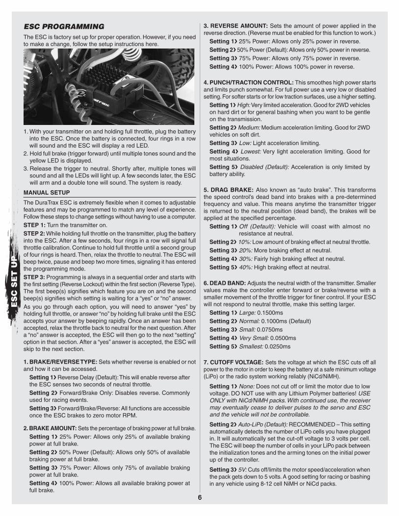
ESC PROGRAMMINGThe ESC is factory set up for proper operation. However, if you need to make a change, follow the setup instructions here.
1. With your transmitter on and holding full throttle, plug the battery into the ESC. Once the battery is connected, four rings in a row will sound and the ESC will display a red LED.
2. Hold full brake (trigger forward) until multiple tones sound and the yellow LED is displayed.
3. Release the trigger to neutral. Shortly after, multiple tones will sound and all the LEDs will light up. A few seconds later, the ESC will arm and a double tone will sound. The system is ready.
MANUAL SETUP
The DuraTrax ESC is extremely flexible when it comes to adjustable features and may be programmed to match any level of experience. Follow these steps to change settings without having to use a computer.STEP 1: Turn the transmitter on.STEP 2: While holding full throttle on the transmitter, plug the battery into the ESC. After a few seconds, four rings in a row will signal full throttle calibration. Continue to hold full throttle until a second group of four rings is heard. Then, relax the throttle to neutral. The ESC will beep twice, pause and beep two more times, signaling it has entered the programming mode.STEP 3: Programming is always in a sequential order and starts with the first setting (Reverse Lockout) within the first section (Reverse Type). The first beep(s) signifies which feature you are on and the second beep(s) signifies which setting is waiting for a “yes” or “no” answer.As you go through each option, you will need to answer “yes” by holding full throttle, or answer “no” by holding full brake until the ESC accepts your answer by beeping rapidly. Once an answer has been accepted, relax the throttle back to neutral for the next question. After a “no” answer is accepted, the ESC will then go to the next “setting” option in that section. After a “yes” answer is accepted, the ESC will skip to the next section.
1. BRAKE/REVERSE TYPE: Sets whether reverse is enabled or not and how it can be accessed.
Setting 1❯ Reverse Delay (Default): This will enable reverse after the ESC senses two seconds of neutral throttle.Setting 2❯ Forward/Brake Only: Disables reverse. Commonly used for racing events.Setting 3❯ Forward/Brake/Reverse: All functions are accessible once the ESC brakes to zero motor RPM.
2. BRAKE AMOUNT: Sets the percentage of braking power at full brake.Setting 1❯ 25% Power: Allows only 25% of available braking power at full brake.Setting 2❯ 50% Power (Default): Allows only 50% of available braking power at full brake.Setting 3❯ 75% Power: Allows only 75% of available braking power at full brake.Setting 4❯ 100% Power: Allows all available braking power at full brake.
3. REVERSE AMOUNT: Sets the amount of power applied in the reverse direction. (Reverse must be enabled for this function to work.)
Setting 1❯ 25% Power: Allows only 25% power in reverse.Setting 2❯ 50% Power (Default): Allows only 50% power in reverse. Setting 3❯ 75% Power: Allows only 75% power in reverse.Setting 4❯ 100% Power: Allows 100% power in reverse.
4. PUNCH/TRACTION CONTROL: This smoothes high power starts and limits punch somewhat. For full power use a very low or disabled setting. For softer starts or for low traction surfaces, use a higher setting.
Setting 1❯ High: Very limited acceleration. Good for 2WD vehicles on hard dirt or for general bashing when you want to be gentle on the transmission.Setting 2❯ Medium: Medium acceleration limiting. Good for 2WD vehicles on soft dirt.Setting 3❯ Low: Light acceleration limiting.Setting 4❯ Lowest: Very light acceleration limiting. Good for most situations. Setting 5❯ Disabled (Default): Acceleration is only limited by battery ability.
5. DRAG BRAKE: Also known as “auto brake”. This transforms the speed control’s dead band into brakes with a pre-determined frequency and value. This means anytime the transmitter trigger is returned to the neutral position (dead band), the brakes will be applied at the specified percentage.
Setting 1❯ Off (Default): Vehicle will coast with almost no resistance at neutral.
Setting 2❯ 10%: Low amount of braking effect at neutral throttle.Setting 3❯ 20%: More braking effect at neutral.Setting 4❯ 30%: Fairly high braking effect at neutral.Setting 5❯ 40%: High braking effect at neutral.
6. DEAD BAND: Adjusts the neutral width of the transmitter. Smaller values make the controller enter forward or brake/reverse with a smaller movement of the throttle trigger for finer control. If your ESC will not respond to neutral throttle, make this setting larger.
Setting 1❯ Large: 0.1500msSetting 2❯ Normal: 0.1000ms (Default)Setting 3❯ Small: 0.0750msSetting 4❯ Very Small: 0.0500msSetting 5❯ Smallest: 0.0250ms
7. CUTOFF VOLTAGE: Sets the voltage at which the ESC cuts off all power to the motor in order to keep the battery at a safe minimum voltage (LiPo) or the radio system working reliably (NiCd/NiMH).
Setting 1❯ None: Does not cut off or limit the motor due to low voltage. DO NOT use with any Lithium Polymer batteries! USE ONLY with NiCd/NiMH packs. With continued use, the receiver may eventually cease to deliver pulses to the servo and ESC and the vehicle will not be controllable.
Setting 2❯ Auto-LiPo (Default): RECOMMENDED – This setting automatically detects the number of LiPo cells you have plugged in. It will automatically set the cut-off voltage to 3 volts per cell. The ESC will beep the number of cells in your LiPo pack between the initialization tones and the arming tones on the initial power up of the controller.
Setting 3❯ 5V: Cuts off/limits the motor speed/acceleration when the pack gets down to 5 volts. A good setting for racing or bashing in any vehicle using 8-12 cell NiMH or NiCd packs.
ES
C S
ET
UP

7
ES
C S
ET
UP
Setting 4❯ 6V: Cuts off/limits acceleration when the pack gets down to 6 volts. Use this setting for 2 cell (7.4V)LiPo packs or you will irreversibly damage your packs!
Setting 5❯ 9V: Cuts off/limits acceleration when the pack gets down to 9 volts. Use this setting for 3 cell (11.1V) LiPo packs or you will irreversibly damage your packs!
Setting 6❯ 12V: Cuts off/limits acceleration when the pack gets down to 12 volts. Use this setting for 4 cell (14.8V) LiPo packs or you will irreversibly damage your packs! However, use of a 4S LiPo pack is not covered under warranty for the 1/10th scale ESC.
8. MOTOR TIMING: Lowering the timing advance will reduce the current draw, increase run time, reduce motor/battery temperatures and may slightly reduce top speed and punch. Increasing the timing advance will do just the opposite.
Setting 1❯ Lowest: A maximum efficiency setting giving long runtimes and cooler motor temperatures. Very useful with high kV (low turn) motors to increase motor life and reduce motor/battery temperatures.
Setting 2❯ Normal (Default): The best mix of speed, punch and efficiency for all motors.
Setting 3❯ Highest: Increases amp draw, reduces runtimes, increases motor/battery temperatures and may increase top speed/punch slightly.
ESC TROUBLESHOOTING
If you’re still having difficulties with your DuraTrax ESC after trying the suggestions offered here, please contact Hobby Services technical support at the e-mail or phone number on page 3.
Problem: My ESC may or may not arm, but it will not calibrate to my transmitter.1. Make sure you have both your throttle and brake endpoints
(called EPA or ATV on your radio) on the throttle channel between 100% to 120%.
2. Make sure if you have a Futaba or Futaba made transmitter to have the throttle channel set to the reversed position.
Problem: My ESC calibrates for the full throttle and full brake positions but won’t calibrate to the neutral throttle position (yellow LED keeps flashing).1. Try moving the throttle trim one way, then the other (usually
towards the throttle side is best).2. If your transmitter has a 50/50 or 70/30 setting for the throttle,
set it for 50/50 and retry calibration. 3. If you have changed the dead band to a narrower band, you may
want to try going back to the “normal” setting.
Problem: My vehicle has poor acceleration/punch for the first few feet or yards, and then it “kicks in”. 1. Make sure you’re using high quality batteries and a battery
connector capable of high amp flow (40-100 amps). This behavior is very typical of a battery pack that is having difficulty providing the power your vehicle/system requires for top performance.
2. If using NiCd/NiMH packs, use copper bars to connect cells rather than welded tabs. Copper bars have a much lower resistance.
Problem: My battery pack is plugged into the ESC and nothing is working – no steering or throttle. 1. Make sure the ESC’s receiver plug is plugged into Channel 2 on
the receiver correctly.2. Double-check your solder connections on the battery plug and
make sure the battery is showing good voltage.
Problem: Overheated motor or hot power plugs.1. The motor is geared too high. Change to a lower gear setup.2. Check for binding in the vehicle’s drive train and that nothing is
interfering with the drive-train.3. Check the motor for shorts, faulty motor connections and replace
if necessary. Problem: Motor runs properly, then goes dead.1. The built-in thermal protection may be automatically shutting
down power to the ESC due to overheating conditions.2. Check for binding drive train, bad motor or incorrect gear ratio.
Check gear mesh, replace motor or change gear ratio. Let the ESC cool down and operation can be reattempted.
Problem: Motor and Rx do not work.Make sure the battery is fully charged and that good contact is being made between the motor battery and ESC and from the ESC to the receiver. Try powering the receiver directly from a separate Rx battery…if the receiver now works, the problem may be the ESC and require servicing.
If the motor runs in reverse after setup, simply swap any two of the motor wires and try again. There is no polarity on the motor to ESC wires and does not matter which two wires are changed.
ESC SPECIFICATIONS
Voltage Input:BEC Max:
Current Rating:Motor Limit:
2S LiPo, 6-7 cell NiCd or NiMH3 Amps @ 2S inputUp to 100AOn 2S: 4200kV Max
ESC PRECAUTIONS
➤ Disconnect the battery from the ESC immediately if the ESC or battery becomes hot!! Allow the ESC or battery to cool down before reconnecting
➤ NEVER use more than the specified voltage on the ESC’s input.
➤ ALWAYS mount the ESC in a position where air can flow through the heat sink during operation.
➤ ALWAYS turn on the transmitter before connecting the battery to the ESC.
➤ ALWAYS disconnect the battery from the ESC when not in use.
➤ Make sure the input battery is fully charged before connecting to the ESC.
➤ DO NOT attempt to use with brushed motors.
➤ Use heat-shrink tubing to insulate any bare wires between the motor battery and ESC, and from the ESC to the motor, to prevent a short circuit.
➤ Allow the ESC to cool before touching.
➤ Do not allow metal/conductive materials to accidentally make contact across any or all motor/battery posts.
➤ Never power up the ESC before plugging it into the RX and switching on the transmitter (TX).
➤ Keep out of reach of children.
➤ DuraTrax is not responsible for incidental damage or personal injury as a result of misuse of this product.

8
TUNING GUIDE:When tuning the Brushless Evader make sure that you have equal length shocks, camber rods and steering rods on both sides (left and right). They do not have to be the same front to rear.
CASTER
Caster refers to the angle which the kingpin is at in relation to the surface when viewed from the side. 0° of caster means that the kingpin is straight up and down. The Brushless Evader comes stock with 30° of caster and is not adjustable.
CAMBER
2° Negative Camber
Adjust
Camber refers to the angle at which the tire and wheel ride in relation to the ground when viewed from the front or rear. Negative camber is when the tire and wheel lean inward and positive camber is when the tire and wheel lean outward. Typically you want 0° to 2° of negative camber. Never put in positive camber. Make sure that both sides have equal amounts of camber by keeping the camber turnbuckles equal in length.
FRONT TOE-IN AND TOE-OUT
1° Toe-In
Front wheels pointed towards each other.
1° 1°
Toe-in and toe-out refer to the angle which the tire is at when viewed from above. Toe-in increases stability under acceleration. However, toe-in also decreases steering when entering a corner. Toe-out will increase steering into corners, but will decrease the overall stability during acceleration. The front typically is set-up with 0° to -2° of toe-in.
WHEEL BASEFront
Long Middle Short
Two washersin front
One washereither side
Two washersin rear
Wheel base is the distance from the center of the front wheel to the center of the rear wheel. Lengthening the wheel base increases steering, but decreases rear traction as a result of increased weight distribution to the front wheels. Decreasing the wheel base will increase rear traction, but decrease steering.
CAMBER LINK PLACEMENT
The camber link placement affects the traction and handling on rough tracks. Using a long mounting position will increase traction but decrease stability. Shortening the link will increase stability, but decrease traction.
SHOCK OILS AND SHOCK SPRINGSMany different combinations can be used between the shock oils and shock springs. Some basic guidelines are that if the rear end is stiff, the vehicle will have more steering and less rear traction. Stiffening the front shocks will result in less steering and more rear traction. Duratrax offers different rate (stiffness) springs to suit most running conditions. The springs are color coded for easy identification:
Front Rear Silver (Extra Soft) DTXC9261 DTXC9260 White (Soft) Included Included Yellow (Medium) DTXC9230 DTXC9235 Green (Hard) DTXC9231 DTXC9236 Green (Hard/Progressive) DTXC9018 DTXC9019
Thinner shock oil will make the shocks react faster, but makes the vehicle less stable and may cause the vehicle to bottom out over large jumps. Thicker shock oil makes the vehicle smoother over large jumps and in straights, but less reactive over rough sections. We have filled the shocks with 30 weight shock oil, which is a good choice for most driving conditions.
TU
NIN
G

9
FRONT SHOCK ADJUSTMENTTop Shock Outer Positions:
More Steering,Faster Suspension Reaction
Inner Mount Positions:More Slow Speed Steering
Outer Mount Positions:More High Speed Steering
Top Shock Inner Positions:Slower Steering,
Smoother Over Bumps
Moving the tops of the shocks out will increase steering and produce quicker suspension reaction, but will result in slower steering reaction. Mounting the bottoms of the shocks in the inside hole of the arms will give more slow speed steering but will take away some high speed steering.
REAR SHOCK ADJUSTMENTTop Shock Outer Positions:
More Steering,More Control Over Bumps
Inner Mount Positions:Less Steering,
Smoother Over Bumps
Outer Mount Positions:More Steering,
Less Control Over Bumps
Top Shock Inner Positions:More Rear Grip,
Smoother Over Bumps
Moving the tops of the shocks in will result in more traction in the corners and greater smoothness over the bumps. Moving the tops of the shocks out will give the vehicle more steering and enable it to handle large jumps better.
DIFFERENTIAL TUNINGThe differential in the Brushless Evader is tunable by using different viscosity of oils. The stock oil is approximately 20,000. If you want less diff action, try using 30,000 or higher. The advantage of less diff action is that the truck will be more controllable during acceleration, have more uniform tire ballooning and less aggressive steering. Going to a lighter oil is not recommended with brushless power as the tire with the least amount of traction will commonly spin (referred to as diffing out) making the truck hard to control.
CLEANING TIPSThe Brushless Evader is fun to drive through the dirt and mud. When it comes time to clean the chassis, here are a few tips:1. Remove the ESC, motor, receiver and steering servo.
Wipe down using a slightly damp cloth.2. Remove the wheels and wash with water. A small scrub
brush works well.3. Rinse off the body and chassis with water.4. Wipe dry thoroughly.5. Relubricate the wheel bearings and servo saver. TIP: To
keep the metal parts from rusting, spray lightly with WD-40.6. Reassemble making sure all parts move free.
MAINTENANCE TIPS:Before Each Run1. Check to make sure that all screws are tight and there are
not any screws missing.2. Check to make sure that the transmitter batteries are not
low.3. Check to make sure that all of the moving parts move
freely and do not bind.4. Check for broken or damaged parts. Replace any broken
or damaged parts before using. Running the Brushless Evader with broken or damaged parts could result in damage to other parts.
5. Check to make sure that the receiver and speed control are still properly secured to the chassis.
6. Check to make sure that all wires are properly connected.7. IMPORTANT! Check the slipper clutch setting. The
Brushless Evader transmission is equipped with a slipper clutch. When properly adjusted the slipper clutch will help to extend the life of the transmission by providing a point that slips when the kit encounters bumps and jolts that would otherwise transfer strain to the internal gears. Although there is no perfect setting for every situation, following the recommended procedure will provide a good starting point. Final adjustments will need to be made with the kit on the actual surface it will be running on.
After Each Run1. Clean any large globs of dirt, mud or debris from the
chassis and moving parts.2. Disconnect and remove the battery.3. Check for any broken or damaged parts. This way parts
may be replaced before the next run.
After Every 10 Runs1. Check the servo saver for proper operation by grasping
the servo arm and linkage and turning one of the front tires left and right. If the wheels turn without moving the linkages and servo arm, then the unit is operating properly. If the linkage and servo arm move, loosen the knurled adjustment nut on the left side servo saver shaft. If the servo saver becomes clogged with dirt, it may not work properly which could cause servo or linkage damage. The servo saver needs to be disassembled, cleaned and readjusted. To safely adjust the servo saver, loosen the knurled aluminum collar on the left side steering post completely. Then reinstall 1-1/2 turns onto the post. Retest the servo saver as described above. Adjust the servo saver tighter or looser if needed.
2. Check to make sure that the bearings are free of dirt and debris and roll smoothly.
3. Check the shocks for oil leakage. If the shocks have leaked any shock fluid out, you should properly refill the shocks for best performance.
4. Check for proper gear mesh between the spur gear and the pinion gear.
TU
NIN
G

10
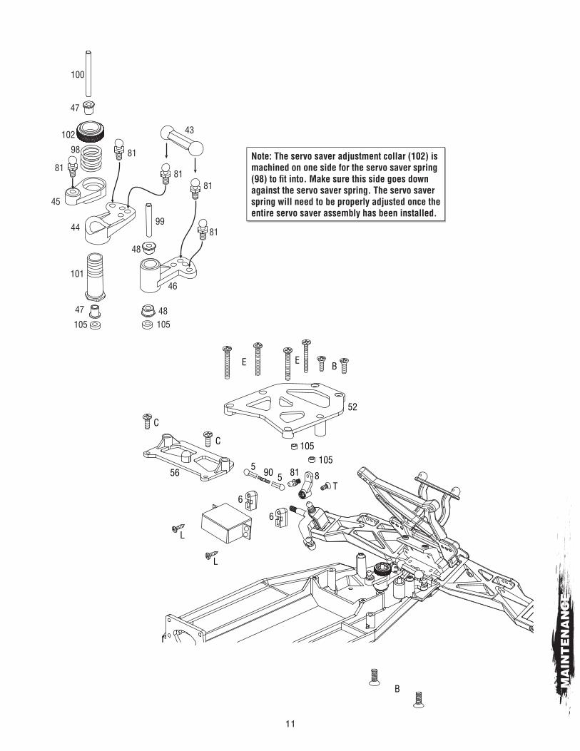
MAINTENANCE GUIDE:The following section is provided to help you with maintenance and repairs to your Brushless Evader. Pay extra attention to the notes and tips for proper assembly.
2
B
C
C
57
81
10438
103
S
S
S
1
K
104S
51
94
94
93
93
91
91
81
81
24 28
28
25
95
95
R
R
R
RR
R
MA
INT
EN
AN
CE
11
Note: The servo saver adjustment collar (102) is machined on one side for the servo saver spring (98) to fi t into. Make sure this side goes down against the servo saver spring. The servo saver spring will need to be properly adjusted once the entire servo saver assembly has been installed.
105105
100
47
48
4847
102
81
81
8181
81
43
99
46101
98
45
44
BE
C
L
L
6
6
9055 81 8
C
56
E
52
105105
T
B MA
INT
EN
AN
CE

12
D40
1
42
3030S
S
41
97
97
OO
C
E
118
118117117
117117
116
116
115
36
37
58
58
O
107
S
S30
108
108
26
9
128
22
79
58
58O
107
S
S
30
108
108
279
128
22
79
MA
INT
EN
AN
CE

13
10
10
22
22
110
110
X
X
12
12
86
86
67
67
11
11
13
13
50
50119
119
119
119
18
14
1414
14
15
19Assemble one half of the diff fi rst. Next, install the internal gears with shims. Fill the differential with 20,000 oil or higher so it is 3/4 full. Install the other side.
G
GG
PP
P
D 20
108
108
108
8921
7 65
17108
92
92
83
5563
Note: When installing the bearings, make sure they are fully seated. If the bearings are not fully seated the gearbox halves may not properly fi t together or may cause binding.
MA
INT
EN
AN
CE

14
84
84
64
64
16
8782
M
HQ
HQ
80
K
Pinion
Motor BackLooser Mesh
Motor ForwardTighter Mesh
GEAR MESH1. Proper gear mesh is critical to achieve long life of your spur gear.2. Install the pinion so it lines up fl ush with the spur.3. Loosen the motor screws and lightly push the two gears together.
Proper mesh will give you full tooth engagement but not be so tight that the gears bind. As a guideline, a good mesh is when you are holding one gear and when you move the other, you can see zero or just a very slight amount of gear lash*.
* Gear Lash is defi ned as the amount of clearance or slack between two gears.
MA
INT
EN
AN
CE

15
4
S75 (Front)76 (Rear)
Fill with oil andslowly move thepiston up and downto remove bubbles.
106
31
122
32
70 (Front)71 (Rear)
34
77
78
114
114
33
3568 (Front)69 (Rear)
Loosely install the cap.
Slowly compress the pistonto bleed out excess oil.
Tighten the cap a little at a time whilemoving the piston up and down tobleed more oil until the cap is tight. M
AIN
TE
NA
NC
E

© 2011 Hobbico®, Inc. All rights reserved.DTXD36xxMNL