د ز - · pdf filemarform mfk 500/600 marwin. ... the motorized, program-controlled change...
TRANSCRIPT
ز� ��� ��اد
آلمان Mahrنماينده انحصاري كمپاني

- +
16- 3 16- 416- 516- 6
16- 816- 916-1016-11
16-1216-15
16-21
- +
MarForm. Form Measur ing Inst ruments
MarForm. Form Measuring Instruments
Formtesters
MarForm M MQ 100 MarForm M MQ 200MarForm M MQ 400-2MarForm. Overv iew standard measur ing machines
Reference Formtesters
MarForm MFU 100MarForm MFU 800MarForm. Overv iew reference and large FormtestersMarForm MFK 500/600
MarWin . Software modules for MarFormSoftware Packages for Special Appl ications
Accessories for MarForm

- +- +
16-2 MarForm. Form Measur ing Inst ruments
MarForm. Formtesters for a Wide Range of Applications FORM MEASURING INSTRUMENTS FOR THE WORKBENCH OR INSPECTION ROOM
There are many aspects of our daily lives where we need to be able to rely on technical components functioning correctly. Take for
example the ABS braking system, injection system or gearbox of a car, the drive of a PC, the compressor in an air-conditioning
system, the blade of an electric razor or the landing flaps of an aircraft. For the moving components to function efficiently over
long periods of time, it is vital they work together smoothly. To ensure this is the case, axis-symmetrical workpieces with narrow
tolerances from the ideal are needed. Compliance with these tolerances can only be verified reliably using precision formtesters
that have been specifically optimized for this application. MarForm helps you to cut process costs without increasing testing
costs thanks to stable, innovative instruments exhibiting the highest possible precision. MarForm offers the ideal solution for all
requirements.

- +- +
16-3MarForm. Form Measur ing Inst ruments
Features
The MarForm MMQ 100 Formtester offers outstanding accuracy in a robust package designed for use in produc-tion environments. Used in combination with EasyForm soft ware, it represents the perfect solution for performing measurement tasks simply, yet effectively.
•Precise and fast measurement results•Reliable thanks to mechanical bearings•Large measuring volume•Mobile due to its low weight and convenient size•Fast computer-assisted workpiece alignment•Centering and tilting screws for rough and fine adjustment•Universal and reliable•Suitable for use on the shop floor as no compressed air
connection is required•No keyboard or mouse required•Digital encoders in Z and X transmit the measuring position
directly to the software
The MMQ 100 can also be operated from a laptop, thereby en-abling mobile use. All you need is a power outlet!
Optimized for the most frequent form measuring tasks
•Roundness(alsoinasection)•Flatness(fromacircle)•Concentricity•Coaxiality•Radialrun-out•Axialrun-out•Planeparallelismfromoppositecircles•Fourier/wavinessanalysis
The Formtester with the simplest operation
MarForm MMQ 100
(1) (1) (1) (1)
(1) from either a single or several polar traces
Versions
MMQ 100 with EasyForm as a powerful, PC-based evaluation system running on Windows®7 offers informative color records with easy-to-use software for evaluation of form and positional tolerances(DINISO1101)suchasroundness,roundnesssector,radial run-out, axial run-out, concentricity, coaxiality, flatness(1), straightness(1), parallelism(1) and perpendicularity(1).
The MMQ 100 EasyForm measuring station comes complete:
Form Measuring Station MMQ 100consisting of:MarFormMMQ100withdigitalencodersinX/ZandwithT20WprobeMeasuring and operating software EasyFormPC Intel class, Windows 7 Ultimate 64 bit24"TFTmonitor
Options for MMQ 100: Advanced Form for comprehensive evaluations, based on EasyForm17"Touch-Screenmonitor
Mahr Data Transfer Tools for simple transfer of measuring results into statistical evaluation programs such as QS-STAT or MS Excel.
Formtester MarForm MMQ 100 EasyForm
RequestabrochureorseeWebCode1412/10146.
- +- +
16-4 MarForm. Form Measur ing Inst ruments
Features
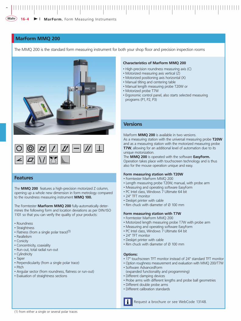
The MMQ 200 features a high-precision motorized Z column, opening up a whole new dimension in form metrology compared to the roundness measuring instrument MMQ 100.
The Formtester MarForm MMQ 200 fully-automatically deter-mines the following form and location deviations as per DIN/ISO 1101 so that you can verify the quality of your products:
• Roundness • Straightness• Flatness (from a single polar trace)(1)
• Parallelism• Conicity• Concentricity, coaxiality• Run-out, total radial run-out• Cylindricity• Taper• Perpendicularity (from a single polar trace)• Pitch• Angular sector (from roundness, flatness or run-out)• Evaluation of straightness sections
The MMQ 200 is the standard form measuring instrument for both your shop floor and precision inspection rooms
MarForm MMQ 200
(1)
Versions
Request a brochure or see WebCode 13148.
Characteristics of MarForm MMQ 200
• High-precision roundness measuring axis (C)• Motorized measuring axis vertical (Z)• Motorized positioning axis horizontal (X)• Manual tilting and centering table• Manual length measuring probe T20W or • Motorized probe T7W• Ergonomic control panel, also starts selected measuring
programs (P1, P2, P3)
MarForm MMQ 200 is available in two versions. As a measuring station with the universal measuring probe T20W and as a measuring station with the motorized measuring probe T7W, allowing for an additional level of automation due to its unique motorization. The MMQ 200 is operated with the software EasyForm. Operation takes place with touchscreen technology and is thus also for the mouse operation unique and easy.
Form measuring station with T20W• Formtester MarForm MMQ 200• Length measuring probe T20W, manual, with probe arm• Measuring and operating software EasyForm• PC Intel class, Windows 7 Ultimate 64 bit• 24“ TFT monitor• Deskjet printer with cable• Rim chuck with diameter of Ø 100 mm
Form measuring station with T7W• Formtester MarForm MMQ 200• Motorized length measuring probe T7W with probe arm• Measuring and operating software EasyForm• PC Intel class, Windows 7 Ultimate 64 bit• 24“ TFT monitor• Deskjet printer with cable• Rim chuck with diameter of Ø 100 mm
Options:• 17“ touchscreen TFT monitor instead of 24“ standard TFT monitor• Option roughness measurement and evaluation with MMQ 200/T7W• Software AdvancedForm
(expanded functionality and programming)• Different clamping devices• Probe arms with different lengths and probe ball geometries• Different double probe arms• Different calibration standards
(1) from either a single or several polar traces
- +- +
16-5MarForm. Form Measur ing Inst ruments
MarForm MMQ 400-2
Features
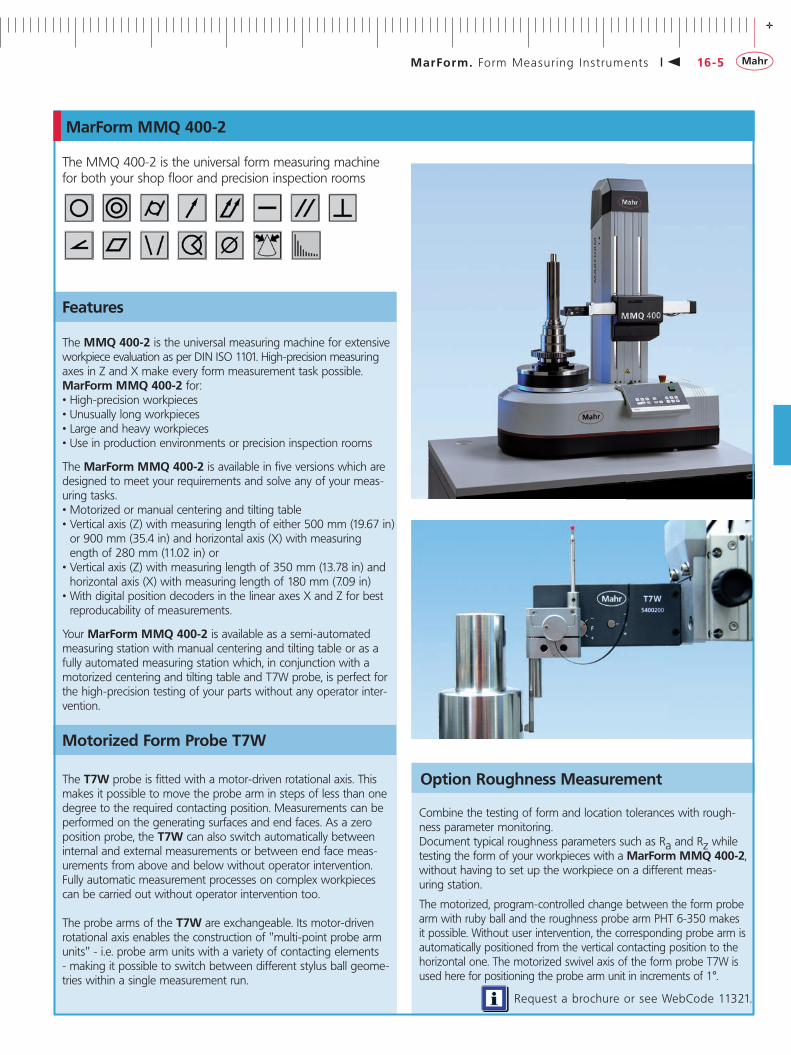
TheMMQ400-2istheuniversalformmeasuringmachinefor both your shop floor and precision inspection rooms
The MMQ 400-2 is the universal measuring machine for extensive workpieceevaluationasperDINISO1101.High-precisionmeasuring axes in Z and X make every form measurement task possible. MarForm MMQ 400-2 for:•High-precision workpieces •Unusually long workpieces •Large and heavy workpieces •Use in production environments or precision inspection rooms
The MarForm MMQ 400-2 is available in five versions which are designed to meet your requirements and solve any of your meas-uring tasks.•Motorized or manual centering and tilting table•Verticalaxis(Z)withmeasuringlengthofeither500mm(19.67in)or900mm(35.4in)andhorizontalaxis(X)withmeasuringengthof280mm(11.02in)or•Verticalaxis(Z)withmeasuringlengthof350mm(13.78in)andhorizontalaxis(X)withmeasuringlengthof180mm(7.09in)•With digital position decoders in the linear axes X and Z for best
reproducability of measurements.
Your MarForm MMQ 400-2 is available as a semi-automated measuring station with manual centering and tilting table or as a fully automated measuring station which, in conjunction with a motorized centering and tilting table and T7W probe, is perfect for the high-precision testing of your parts without any operator inter-vention.
The T7W probe is fitted with a motor-driven rotational axis. This makes it possible to move the probe arm in steps of less than one degree to the required contacting position. Measurements can be performed on the generating surfaces and end faces. As a zero position probe, the T7W can also switch automatically between internal and external measurements or between end face meas-urements from above and below without operator intervention. Fully automatic measurement processes on complex workpieces can be carried out without operator intervention too.
The probe arms of the T7W are exchangeable. Its motor-driven rotationalaxisenablestheconstructionof"multi-pointprobearmunits"-i.e.probearmunitswithavarietyofcontactingelements- making it possible to switch between different stylus ball geome-tries within a single measurement run.
Motorized Form Probe T7W
RequestabrochureorseeWebCode11321.
Option Roughness Measurement
Combine the testing of form and location tolerances with rough-ness parameter monitoring.Document typical roughness parameters such as Ra and Rz while testing the form of your workpieces with a MarForm MMQ 400-2, without having to set up the workpiece on a different meas-uring station.
The motorized, program-controlled change between the form probe armwithrubyballandtheroughnessprobearmPHT6-350makesit possible. Without user intervention, the corresponding probe arm is automatically positioned from the vertical contacting position to the horizontal one. The motorized swivel axis of the form probe T7W is usedhereforpositioningtheprobearmunitinincrementsof1°.
- +- +
16-6 MarForm. Form Measur ing Inst ruments
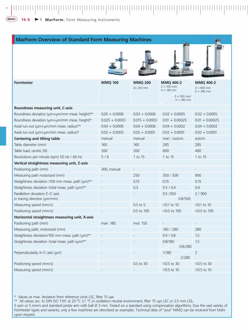
MarForm Overview of Standard Form Measuring Machines
Formtester MMQ 100 MMQ 200Z=250mm
MMQ 400-2Z=350mm/X=180mm
Z=500mm/X=280mm
MMQ 400-2 Z=900mmX=280mm
Roundness measuring unit, C-axis
Roundnessdeviation(µm+µm/mmmeas.height)** 0.05+0.0006 0.03+0.0006 0.02+0.0005 0.02+0.0005
Roundnessdeviation(µm+µm/mmmeas.height)* 0.025+0.0003 0.015+0.0003 0.01+0.00025 0.01+0.00025
Axialrun-out(µm+µm/mmmeas.radius)** 0.04+0.0006 0.04+0.0006 0.04+0.0002 0.04+0.0002
Axialrun-out(µm+µm/mmmeas.radius)* 0.02+0.0003 0.02+0.0001 0.02+0.0001 0.02+0.0001
Centering and tilting table manual manual man./autom. autom.
Tablediameter(mm) 160 160 285 285
Tableload,centric(N) 200 200 600 400
Revolutionsperminute(rpm)50Hz/60Hz 5/6 1to15 1to15 1to15
Vertical straightness measuring unit, Z-axis
Positioningpath(mm) 300,manual - - -
Measuringpathmotorized(mm) - 250 350/500 900
Straightnessdeviation/100mmmeas.path(µm)** - 0.15 0.15 0.15
Straightnessdeviation/totalmeas.path(µm)** - 0.3 0.3/0.4 0.4
ParallelismdeviationZ-/C-axisintracingdirection(µm/mm)
- - 0.5/3500.8/500
2/900
Measuringspeed(mm/s) - 0.5to5 <0.1to10 <0.1to10
Positioningspeed(mm/s) - 0.5to100 <0.5to100 <0.5to100
Horizontal straightness measuring unit, X-axis
Positioningpath(mm) man.180. mot.150 - -
Measuringpath,motorized(mm) - - 180/280 280
Straightnessdeviation/100mmmeas.path(µm)** - - 0.4/0.8 1.5
Straightnessdeviation/totalmeas.path(µm)** - - 0.8/1800.8/280
1.5
PerpendicularityX-/C-axis(µm) - - 1/1802/280
2
Positioningspeed(mm/s) - 0.5to30 <0.5to30 <0.5to30
Measuringspeed(mm/s) - - <0.5to10 <0.5to10
*Valuesasmax.deviationfromreferencecircleLSC,filter15upr.**Allvaluesacc.toDINISO1101at20°C±1°Cinoscillation-neutralenvironment,filter15uprLSCor2.5mmLSS,5rpmor5mm/sandstandardprobearmwithballØ3mm.Testedonastandardusingcompensationalgorithms.Due the vast variety of Formtestertypesandvariants,onlyafewmachinesaredescribedasexamples.Technicaldataof“your”MMQcanbereceivedfromMahrupon request.
- +- +
16-7MarForm. Form Measur ing Inst ruments
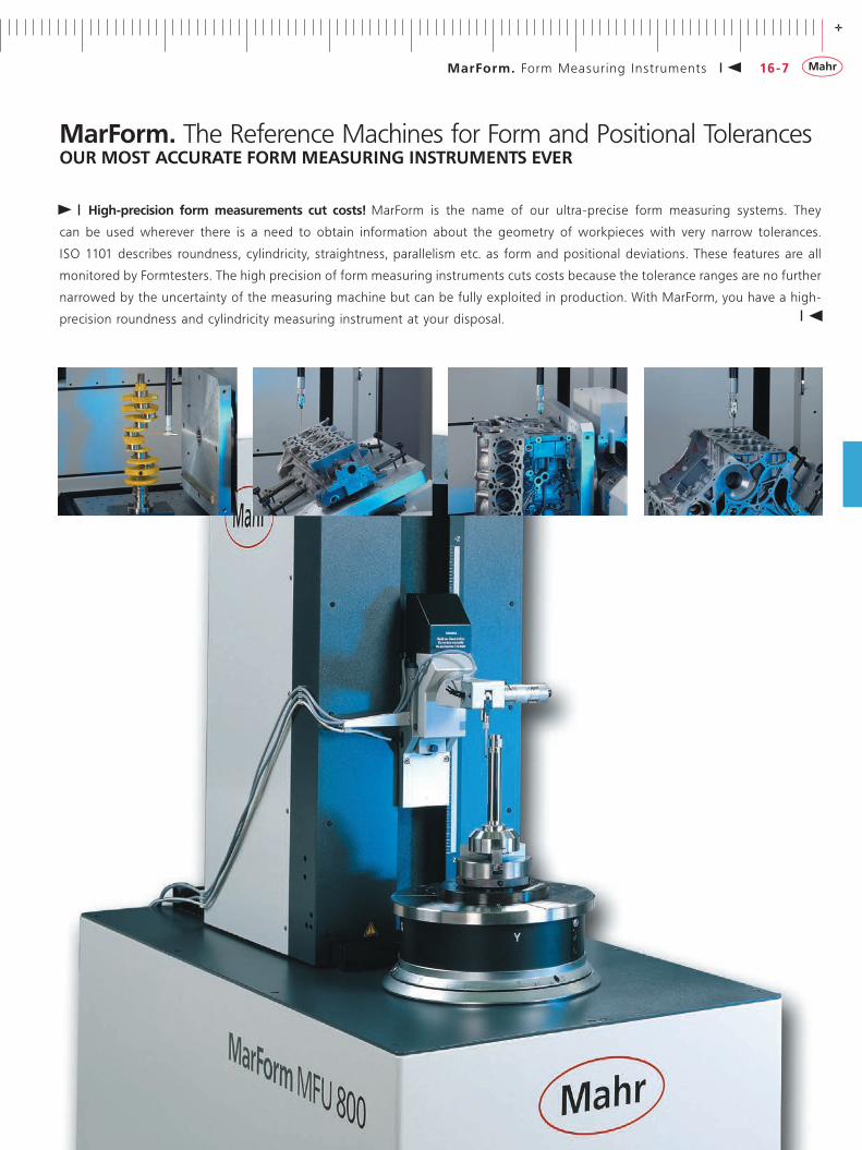
MarForm. The Reference Machines for Form and Positional Tolerances OUR MOST ACCURATE FORM MEASURING INSTRUMENTS EVER
High-precision form measurements cut costs! MarForm is the name of our ultra-precise form measuring systems. They
can be used wherever there is a need to obtain information about the geometry of workpieces with very narrow tolerances.
ISO1101describes roundness, cylindricity, straightness,parallelismetc. as formandpositionaldeviations.These featuresareall
monitored by Formtesters. The high precision of form measuring instruments cuts costs because the tolerance ranges are no further
narrowed by the uncertainty of the measuring machine but can be fully exploited in production. With MarForm, you have a high-
precision roundness and cylindricity measuring instrument at your disposal.

- +- +
16-8 MarForm. Form Measur ing Inst ruments
MarForm MFU 100
Features
The MarForm MFU 100 comes complete with:
•Roundnessaxis,circular(C)•Motorizedcenteringandtiltingtable(X,Y,A,B)•Straightnessmeasuringaxis,vertical(Z)•Straightnessmeasuringaxis,horizontal(X)•Tangentialmulti-functionaxis(Y)•MotorizedprobeT7W•MarWinevaluationsoftwareforformandpositionalfeatures
All the axes are coordinated to ensure maximum measuring certainty.The horizontal X-axis extends beyond the center of the workpiece, thereforemakingitpossibletotestthe“trueparallelism”freefromother measuring influences.The tangential Y-axis is a new and innovative feature. For con-ventional formtesters. It makes it possible to locate the zenith of very small workpiece geometries automatically and free from user influence. This means that the actual precision measurement can be started at exactly the right location, thus significantly increasing the process accuracy.
In addition, the tangential Y-axis, in combination with the vertical Z-axis and the horizontal X-axis, enables you to determine the workpiecediameter.Atauniqueprice/performanceratio,thisaxismakesitnowpossibletoverifytolerancesinthesub-µmrangeaccording to standards using the maximum material principle.
Taking reference form measurement to a new level
The road from high-precision measuring axes to reliable measure-ments is often a long one – and no instrument is better suited for this purpose than the MFU 100. Only the MFU 100 has integrated reference elements for real-time spatial compensation of geometri-cal deviations and therefore records all profiles as high-precision 3Dcoordinates.
For decades, MarForm measuring instruments have been re-nowned for their precision and stability. The new MarForm MFU 100 was developed with the objective of testing the form and positional features of parts with measuring volumes of a liter cost-effectively in a production environment. Our many years of experience have taken the new MFU 100 to a new level.
With the MarForm MFU 100, you have a high-precision meas-uring instrument at your disposal whose extremely low measuring uncertainty increases the tolerance range in production environ-ments and thus cuts production costs.
RequestabrochureorseeWebCode1336.
In combination with the machine electronics, high-resolution digital scales ensure a level of positioning quality that makes it possible to test even the smallest component geometries. The MarForm MFU 100 is also ideally suited to scanning surfaces.
The MarWin software package offers the complete range of functions you would expect from a modern measuring and evaluation software package, including attractive records and electronic documentation in your corporate network.
Due to the deliberate separation of control and evaluation, the MarForm MFU 100 is future-proof and expandable. New language versions, special evaluations and new standards can all be incorporated with ease. The MFU 100 has also been designed to accommodate sensors developed in the future.
In short, the MarForm MFU 100 represents a new generation of reference form measuring instrument for precision inspection rooms and production environments.
The new MarForm MFU 100 WP is also available with an optionalopticalsensortoalternatewiththeT7W(motorized).
- +- +
16-9MarForm. Form Measur ing Inst ruments
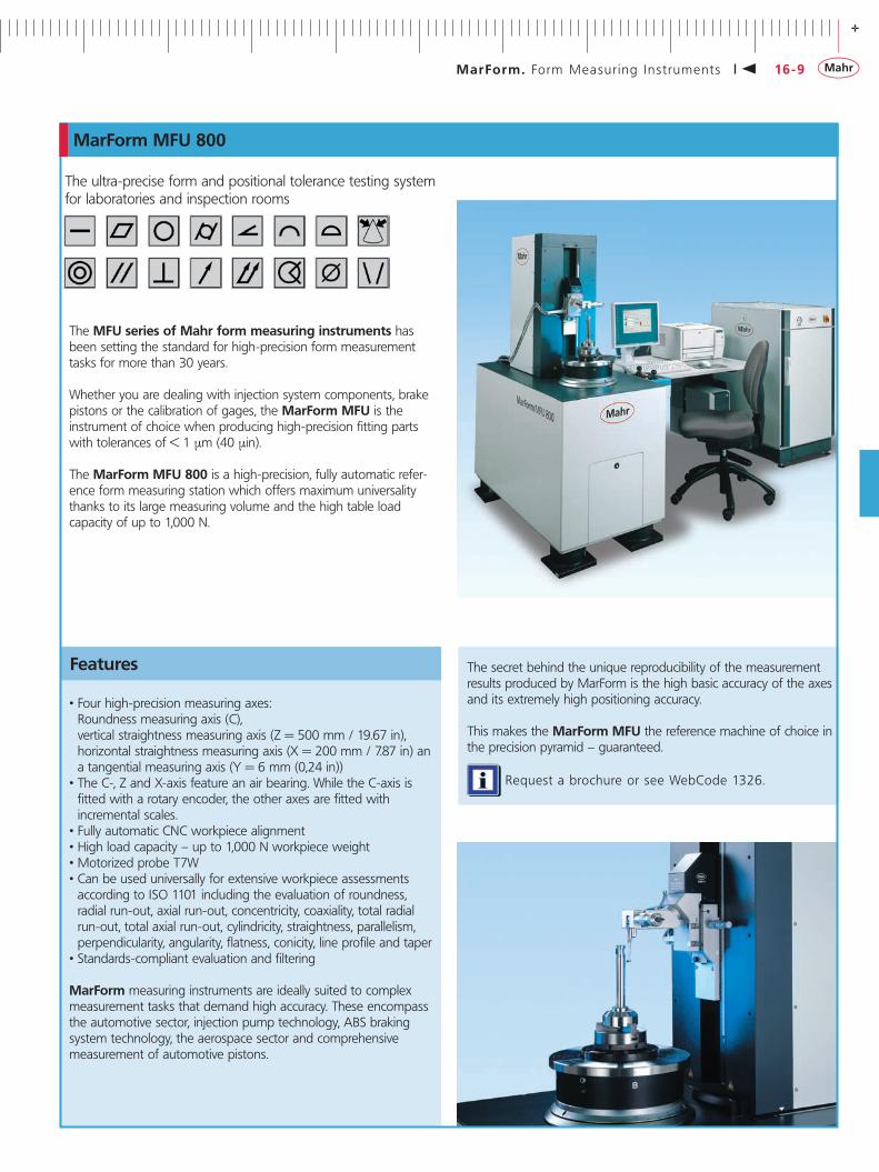
MarForm MFU 800
Features
•Four high-precision measuring axes: Roundnessmeasuringaxis(C),verticalstraightnessmeasuringaxis(Z=500mm/19.67in),horizontalstraightnessmeasuringaxis(X=200mm/7.87in)anatangentialmeasuringaxis(Y=6mm(0,24in))•The C-, Z and X-axis feature an air bearing. While the C-axis is
fitted with a rotary encoder, the other axes are fitted with incremental scales.•Fully automatic CNC workpiece alignment•Highloadcapacity–upto1,000Nworkpieceweight•Motorized probe T7W•Can be used universally for extensive workpiece assessments accordingtoISO1101includingtheevaluationofroundness,radial run-out, axial run-out, concentricity, coaxiality, total radial run-out, total axial run-out, cylindricity, straightness, parallelism, perpendicularity, angularity, flatness, conicity, line profile and taper •Standards-compliant evaluation and filtering
MarForm measuring instruments are ideally suited to complex measurement tasks that demand high accuracy. These encompass the automotive sector, injection pump technology, ABS braking system technology, the aerospace sector and comprehensive measurement of automotive pistons.
The secret behind the unique reproducibility of the measurement results produced by MarForm is the high basic accuracy of the axes and its extremely high positioning accuracy.
This makes the MarForm MFU the reference machine of choice in the precision pyramid – guaranteed.
The ultra-precise form and positional tolerance testing system for laboratories and inspection rooms
The MFU series of Mahr form measuring instruments has been setting the standard for high-precision form measurement tasksformorethan30years.
Whether you are dealing with injection system components, brake pistons or the calibration of gages, the MarForm MFU is the instrument of choice when producing high-precision fitting parts withtolerancesof<1µm(40µin).
The MarForm MFU 800 is a high-precision, fully automatic refer-ence form measuring station which offers maximum universality thanks to its large measuring volume and the high table load capacityofupto1,000N.
RequestabrochureorseeWebCode1326.

- +- +
16-10 MarForm. Form Measur ing Inst ruments
Formtester
MFU 800
MFU 100
Roundness measuring device, C-axisRoundnessdeviation(µm+µm/mmmeas.height)** 0.02+0.0004 0.02+0.0004
Roundnessdeviation(µm+µm/mmmeas.height)* 0.01+0.0002 0.01+0.0002
Axialrun-outdeviation(µm+µm/mmmeas.radius)** 0.04+0.0002 0.04+0.0004
Axialrun-outdeviation(µm+µm/mmmeas.radius)* 0.02+0.0001 0.02+0.0002
Resolution(interpolated) 0.0005° 0.0001°
Centering and tilting table automatic automatic
Tablediameter(mm) 300 180
Tableloadcapacity,centric(N) 1,000 200
Speed(rpm)50Hz/60Hz 0.1to15 0.1to15
Vertical straightness measuring unit, Z-axis
Measuringpath(mm) 480 320
Straightnessdeviation/100mm(µm)** 0.1 0.1
Straightnessdeviation/200mm(µm)** - 0.2
Straightnessdeviation/measuringpath(µm)** 0.3 0.3
ParallelismdeviationofZ-/C-axisintracingdirection(µm) 0.6 0.6
Measuringspeed(mm/s) 0.1to50 0.1to50
Positioningspeed(mm/s) 0.1to50 0.1to50
Positioninguncertainty(µm)withprobereturnpositioning - 1
Positioninguncertainty(µm) (totalpositioningPtoVDI3441)
10 2
Resolution(interpolated)(µm) 0.001 0.001
Horizontal straightness measuring unit, X-axisMeasuringpath(mm) 180 190
Straightnessdeviation/100mm(µm)** 0.15 0.15
Straightnessdeviation/meas.path(µm)** 0.3 0.3
PerpendicularityofX/C-axis(µm) 0.3 0.3
Measuringspeed(mm/s) 0.1to50 0.1to50
Positioningspeed(mm/s) 0.1to50 0.1to50
Positioninguncertainty(µm)withprobereturnpositioning - 1
Positioninguncertainty(µm) (totalpositioningPtoVDI3441)
4 2
Diametermeasuringaccuracy(µm) 2 0.2
Resolution(interpolated)(µm) 0.001 0.001
Horizontal straightness measuring unit, Y-axis Measuringpath(mm) 6 6
Straightnessdeviation(µm/5mm,filter0.25mm) 0.5 0.5
PerpendicularityY-/X-axis(µm) 1 1
Resolution(interpolated)(µm) 0.005 0.005
MarForm Overview Reference and Large Formtesters
*ValuesasmaximumdeviationfromreferencecircleLSC,filter15upr.**AllvaluesinaccordancewithDINISO1101at20°C±1°Cinvibration-freeenvironment,filter15uprLSCor2.5mmLSS,5rpmor5mm/sandstandardprobearmwithballdia.3mm. Tested on a standard using compensation algorithms.

- +- +
16-11MarForm. Form Measur ing Inst ruments
The reference form measuring centers for laboratories and inspection rooms
MarForm MFK 500 and MFK 600
MFK form measuring center for comprehensive workpiece assessmentMFK formtesters are particularly suited to testing engine blocks, cylinder heads, gearboxes, hydraulic components, crankshafts and camshafts. Generous, optimized construction ensures high measuring accuracy over the entire machine volume. Large measuring and travel paths enable easy and safe changing of workpieces.
The MarForm MFK 600 and MFK 500, made from coordinated components, offer flexibility and can be adapted for a wide range of metrology applications.
The formtester has a distortion-free granite base which is oscillation-isolated. Its high-precision horizontal surface forms the reference plane for the measuring setup. The workpiece mounting table carries and guides heavy workpieces over the granite surface using air bearings.
Features
•Universal form measuring station with large measuring volume for heavy workpieces•The MFK 600has5measuringaxesand2(4)alignmentaxesfor
measuring form elements and determining positions•The MFK 500has3measuringaxesand4alignmentaxesfor
measuring form elements •Rotating probe and automatically positioned workpieces for easy
use and quick setup•Low maintenance and able to handle continuous loads thanks to
air bearings•Collision-protected probe systems for a wide range of measure-
ment tasks•Large workpiece mounting area for large individual workpieces
or pallets holding several workpieces•Roundness measuring unit with automatic adjustment to the
diameter of the workpiece even if the position is eccentric•Straightnessmeasurementsin3maincoordinatedirections•ISO1101-compliantworkpieceevaluation•Testing in machine and workpiece coordinates in line with
manufacturing requirements•Comprehensive evaluation of form and positional features,
diameters and positional values•A wide range of accessories and probes offer an optimum
solution for all measurement tasks•Easily expandable with additional axes of movement for rotating
workpieces while the program is running. This means that highly complex measurement tasks, such as those required for V engine blocks, can be performed without operator intervention
Roundness measuring unitInadditiontothemeasuringspindle(C-axis),theroundnessmeas-uring unit includes an axis for automatically adjusting the probe totheworkpiecediameter(X-axis).Whenperformingroundnessmeasurements, the X-axis positions the probe such that it tracks the contour of the workpiece, even it its eccentricity error exceeds the probe measuring range.
Straightness measuring unitTheverticalstraightnessmeasuringunit(Z-axis)guidestheround-ness measuring unit along a granite surface. With the MFK 600, theaccuracyofthehorizontalstraightnessmeasuringunit(Tx- and Ty-axes)isnotaffectedbytheworkpiece’ssize,formorweightbecause the guides are separated from the supporting air bearings. With the MFK 500, the Tx/Ty-axes of the motorized centering and tilting table are also used as positioning axes.
The alignment axes(Ta and Tb)areintegratedintheworkpiecemounting table and can automatically align workpieces mechani-cally within the machine volume. Measuring capacityAutomatic alignment functions integrated in measuring runs allow continuous operation. Recording and processing measured values in parallel cuts the measurement time. Theformmeasuringstation’s range of applications is extended by a comprehensive range of accessories.
RequestabrochureorseeWebCode1307.
- +- +
16-12 MarForm. Form Measur ing Inst ruments
MarWin. Software Modules for MarForm
AdvancedForm gives you total control over your form measuring station. You can perform positioning, alignment, measurement or documentation tasks with a click of the mouse – and the graphical user interface gives you a constant overview.
As with other Windows® applications, functions can be selected from menu bars with pull-down menus using the mouse. Many functions, such as printing results, loading measuring programs or changing a program step, can be activated simply by clicking the appropriate icons.
With AdvancedForm you always have complete control over the form measuring station. For example, you can track the profile dur-ing measurement and intervene if necessary. Operation can be adapted to suit individual requirements, regardless of whether you want to perform a quick single measurement, conduct a program run on a series part or convert a complex measurement task into a measuring program. AdvancedForm provides the ideal operating strategy whatever the task. Given that tasks can vary a great deal, no operating strategy is exactly right for every application.
AdvancedForm provides a clear overview of all the required measuring and evaluation parameters. Many of these parameters have default settings which simply have to be confirmed for the majority of measurement tasks. It is, of course, also possible to adapt individual parameters to the relevant task.
AdvancedForm has a powerful teach-in programming function to create measuring programs for workpieces that are to be measured repeatedly. It can also be used for measuring runs with special positionings, measurements, evaluations and forms of presentation.
With teach-in programming, as soon as you click the mouse on an icon – e.g. for a run-out measurement and evaluation – a window opens where you can describe the feature in more detail if neces-sary (e.g. radial or axial run-out, datum, brief designation, tolerance, etc.). The number of measurements and their type (measurement or re-evaluation of profiles already measured) are also specified in this window. Separate windows can be opened to change measuring, evaluation and display parameters but in many cases this is not necessary because logical defaults that apply to a large number of measurement tasks have already been entered. If different settings are required for specific measurement tasks, the clearly structured window helps you to quickly find what you are looking for and optimize the settings in no time at all.
The layout of a measuring record, for example, can be modified right down to the finest detail. The color of the profile, reference line and borders can be selected individually; the scaling (in μm/μin per scale division), the type of graph (polar or linear, centered or uncentered) and the additional display parameters can be set in any combination you choose.
Measuring programs for series parts to be measured repeatedly can be saved and called up at any time to start a measuring run (see above).
Informative profile graphs – if required with several profiles in a single graph, displayed in different colors and in different ways – are then immediately available on the large color screen. If you are looking for exact numerical values, you can opt to display the results in a table.
With the new AdvancedForm, standards-compliant measurements and evaluations are displayed in a way which is both clear and representative. Even interactive layout options with a 3D preview in real time are possible.
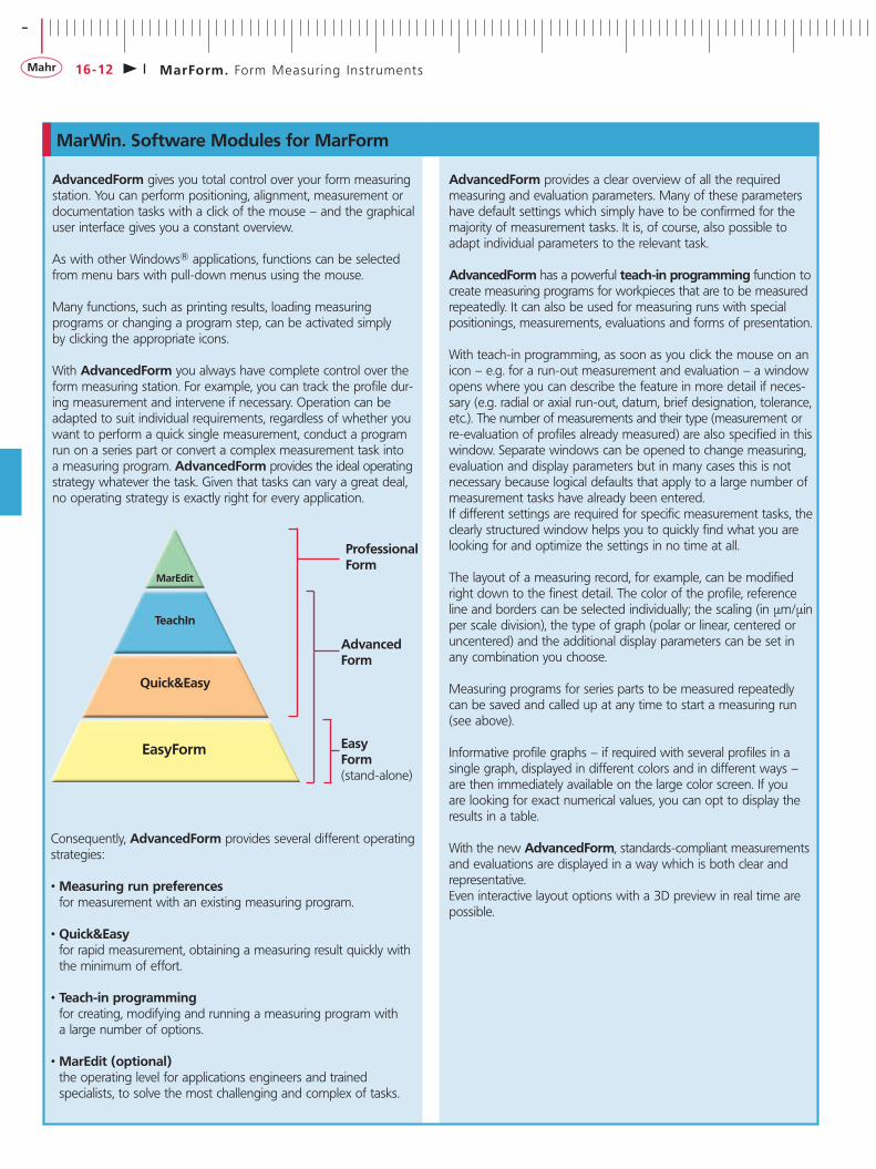
Consequently, AdvancedForm provides several different operating strategies:
•Measuring run preferences for measurement with an existing measuring program.
•Quick&Easy for rapid measurement, obtaining a measuring result quickly with the minimum of effort.
•Teach-in programming for creating, modifying and running a measuring program with a large number of options.
•MarEdit (optional) the operating level for applications engineers and trained specialists, to solve the most challenging and complex of tasks.
Professional Form
Advanced Form
Easy Form(stand-alone)
EasyForm
Quick&Easy
TeachIn
MarEdit

- +- +
16-13
Teach-in listing
MarForm. Form Measur ing Inst ruments
MarWin. Software Moduls for MarForm
MarWin software modules in detail
If you need to carry out form measurements, rather than creating long measuring programs you may prefer to gain direct access to a comprehensive and informative measuring record. In order to be able to do so, it is particularly important for the software to be transparent. Immediately after logging on in the MarWin user administration, you are directed to the MarShell, a clearly arranged user interface comparable with the Windows Desktop. It is from this MarShell that you start the finished measuring programs in the Preferences view. These preferences can be easily identified by each operator due to expressive images and icons aleady saved to the system. One click is all that is needed to start the measuring program.The MarShell is also used to start the measuring wizard module, Quick&Easy (QE).
The Quick&Easy wizards provide support for “quick measurements by the fly" and, with little effort, guide the user quickly to his objective, namely a highly informative measuring record. A further click results in all Quick&Easy wizards that have so far been run being adopted as a chronological sequence into teach-in programming function of AdvancedForm/MarWin. This sequence merely has to be saved and the measuring program is then ready.In AdvancedForm, additional functions can be added to the measuring program. The following Quick&Easy wizards assist in this process:
1 . PR E PARATION FOR M EASu R E M E NT
• QE Determine starting position• Measuring station, positioning• QE Axial run-out alignment• QE Centering• QE Centering and tilting
• QE Set parameters• QE Zenith• QE Edge search• QE Switch coordinate system• QE Move to calculated position
2. PROFILE RECORDING
• QE Circles on cylinder• QE Circles on plane/end face• QE Lines on cylinder• QE Lines on plane/end face
Preferences view for starting the measuring programs
Quick&Easy Roundness

- +- +
16-14 MarForm. Form Measur ing Inst ruments
• QE Axis• QE Plane
• QE Roundness• QE Cylindricity• QE Coaxiality• QE Concentricity
• QE Radial run-out• QE Total radial run-out
• QE Straightness• QE Parallelism• QE Conicity• QE Angularity• QE Perpendicularity
• QE Axial run-out• QE Total axial run-out• QE Flatness• QE Taper
4. SPECIAL EVALUATION
• QE Fourier analysis• QE Fourier synthesis (optional)• QE Profile arithmetics•QE Roughness measurement (optional)•QE Contour measurement (optional)•QE Diameter measurement (optional)•QE Tolerance band evaluation (optional)•QE Cam evaluation (optional)•QE Dominant Roundess Waviness (optional)
MarWin. Software Modules for MarForm
5. R ECOR D
•QE Multigraphics
Multigraphic record
6. DATA EXPORT
•QE Result export (optional)•QE QS-STAT (optional)
3. EVALUATION
- +- +
16-15
MarWin2.04-05 SP 12
12.07.07 113:49:45Prüfer:
JacobsenUnterschrift:
Teil: Zeichnungs-Nr.: Bearbeitungsschritt:
Kommentar:
Mahr GmbHKolbenmessungD- 37073 Göttingen
Firma :
Zeichnung :
Auftrag :
Laufzeit :
Kern :
Laufspiel :
Motor Nr :
Bericht : Teil Nr :
Abwicklung
Test_Firma kolben_123
Ovalauswertung H = 12.0 mm
0°
90°
100.00 µm
(1)_oval_fit_Messtakt pol.: 0.10°Tastkugel ø: 20.0000 mmgefiltert: 50 W /U50% GaussVerstärkung: 1F: 0.05 N
Messweg
Profil
(1)_oval_fit_
30.00 °50.00 µm
Tabellarische Ergebnisdarstellung 0°- 180°: Tabellarische Ergebnisdarstellung 180°- 360°:
Pos[°] Nennm.[mm OT [mm] UT [mm] Istmaß[mm] Abw. [mm] Pos[°] Nennm.[mm OT [mm] UT [mm] Istmaß[mm] Abw. [mm]0,000 0,000 0,002 -0,002 -0,000 0,000 185,000 -0,002 0,004 -0,004 -0,004 0,0025,000 -0,002 0,004 -0,004 -0,003 0,001 190,000 -0,007 0,004 -0,004 -0,009 0,002
10,000 -0,007 0,004 -0,004 -0,007 -0,000 195,000 -0,016 0,004 -0,004 -0,018 0,00115,000 -0,016 0,004 -0,004 -0,017 0,001 200,000 -0,029 0,006 -0,006 -0,029 -0,00020,000 -0,029 0,004 -0,004 -0,030 0,000 205,000 -0,045 0,006 -0,006 -0,044 -0,00225,000 -0,045 0,006 -0,006 -0,045 -0,000 210,000 - 0,007 -0,007 0,000 -30,000 - 0,007 -0,007 0,000 - 225,000 - 0,009 -0,009 0,000 -45,000 - 0,009 -0,009 0,000 - 240,000 - 0,011 -0,011 0,000 -60,000 - 0,011 -0,011 0,000 - 270,000 - 0,016 -0,016 0,000 -90,000 - 0,016 -0,016 0,000 - 300,000 - 0,011 -0,011 0,000 -
120,000 - 0,011 -0,011 0,000 - 315,000 - 0,009 -0,009 0,000 -135,000 - 0,009 -0,009 0,000 - 330,000 -0,065 0,007 -0,007 -0,066 0,001150,000 -0,065 0,007 -0,007 -0,065 -0,000 335,000 -0,045 0,006 -0,006 -0,046 0,000155,000 -0,045 0,006 -0,006 -0,045 -0,000 340,000 -0,029 0,006 -0,006 -0,029 -0,001160,000 -0,029 0,006 -0,006 -0,028 -0,001 345,000 -0,016 0,004 -0,004 -0,015 -0,001165,000 -0,016 0,004 -0,004 -0,015 -0,001 350,000 -0,007 0,004 -0,004 -0,006 -0,001170,000 -0,007 0,004 -0,004 -0,007 -0,001 355,000 -0,002 0,004 -0,004 -0,001 -0,001175,000 -0,002 0,004 -0,004 -0,002 0,001 360,000 0,000 0,002 -0,002 0,000 0,000180,000 0,000 0,002 -0,002 -0,002 0,002
Merkmal Nenn. o.Tol. u.Tol. Ist Abw.
90°00'00" 3°00'00" -3°00'00" 88°39'30" -1°20'30"Ovallage - Bohrung
Merkmal Nenn. o.Tol. u.Tol. Ist Abw.
0,000 0,000 -0,000 -0,000 -0,000d_x (0/180°)0,000 0,000 -0,000 -0,000 -0,000d_y (90/270°)
MarForm. Form Measur ing Inst ruments
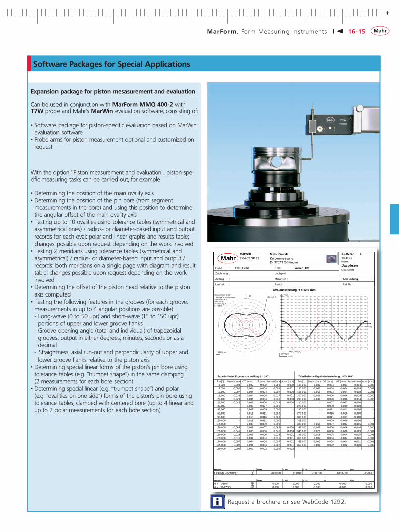
Software Packages for Special Applications
Request a brochure or see WebCode 1292.
Expansion package for piston mesasurement and evaluation
Can be used in conjunction with MarForm MMQ 400-2 with T7W probe and Mahr’s MarWin evaluation software, consisting of:
•Software package for piston-specific evaluation based on MarWin evaluation software•Probe arms for piston measurement optional and customized on
request
With the option "Piston measurement and evaluation", piston spe-cific measuring tasks can be carried out, for example
•Determining the position of the main ovality axis•Determining the position of the pin bore (from segment
measurements in the bore) and using this position to determine the angular offset of the main ovality axis•Testing up to 10 ovalities using tolerance tables (symmetrical and
asymmetrical ones) / radius- or diameter-based input and output records for each oval: polar and linear graphs and results table; changes possible upon request depending on the work involved•Testing 2 meridians using tolerance tables (symmetrical and
asymmetrical) / radius- or diameter-based input and output / records: both meridians on a single page with diagram and result table; changes possible upon request depending on the work involved•Determining the offset of the piston head relative to the piston
axis computed •Testing the following features in the grooves (for each groove,
measurements in up to 4 angular positions are possible)- Long-wave (0 to 50 upr) and short-wave (15 to 150 upr) portions of upper and lower groove flanks- Groove opening angle (total and individual) of trapezoidal grooves, output in either degrees, minutes, seconds or as a decimal- Straightness, axial run-out and perpendicularity of upper and lower groove flanks relative to the piston axis•Determining special linear forms of the piston’s pin bore using
tolerance tables (e.g. “trumpet shape“) in the same clamping (2 measurements for each bore section)•Determining special linear (e.g. “trumpet shape“) and polar
(e.g. “ovalities on one side“) forms of the piston’s pin bore using tolerance tables, clamped with centered bore (up to 4 linear and up to 2 polar measurements for each bore section)

- +- +
16-16 MarForm. Form Measur ing Inst ruments
MarWin. Lead Measurement and Analysis with MarForm Formtesters
Measured value acquisition
The surface structure of the sealing surface of a shaft influences the flow behaviour of the fluid that is to be sealed and therefore greatly influences the sealing function.
A lead structure on the sealing surface can interfere with both the shaft surface, fluid and sealing lip contact length creating leakage due to a conveying effect.
Lead is a surface feature appearing over the entire circumference on rotationally symmetrical surfaces. The evaluation of the macro lead is conducted with the option "Lead measurement" as per the Mercedes Benz Standard 31007-7.
Measurement of n generating lines (72 as per MB Standard, MBN 31007-7)
A T7W probe arm with two styli is used to assess the measuring values.
•Stylus # 1 with 3 mm hard metal ball for mechanically centering and tilting of the workpiece on the Formtester•Stylus # 2 with diamond stylus tip for measuring lead and surface
roughness parameters
Scope of application
External measurement on workpiece diameters between 2 and 200 mm
Description
Expansion package for MarForm Formtesters as per Mercedes Benz Standard MBN31007-7, version 2
Expansion package: Lead measurement and analysis
For use on MarForm MMQ 200, MMQ 400-2, MFU 100 with motorized probe T7W and the Mahr evaluation software MarWin, consisting of:
•Software package "Lead mesurement and analysis" based on MarWin evaluation software •T7W probe arm unit for lead measurement, double-ended with
diamond tip 5 μm and 3 mm hard metal ball for alignment (5400234)
Order no.: 5440675
Request a brochure or see WebCode 1292.

- +- +
16-17MarForm. Form Measur ing Inst ruments
Expansion Package for MarForm Formtesters. Lead Measurement and Analysis
Form and lead evaluation•Form/positional evaluation for conicity / parallelism /
parallel to lead evaluation•Form/positional/lead evaluation of several upr values
Evaluation and recordingAfter the measurements have been performed, measurement records with the following content are generated:
Lead parameters:•Number of threads DG (upr) •Period length DP (mm) •Lead angle Dγ (degrees)•Lead direction•Lead depth Dt (μm)•Theoretical supply cross section DF (μm2)•Theoretical supply cross section per turn DFu (μm/U)•Contact length of radial seal DLu (%)
Graphic output:
The measured profiles are output in the record as graphs.Various diagram types are available:•3D cylinder (in color, traditional and unwound)•Every assessed generating line profile is shown in a linear graph
to juede the form and the positional parameters.•Amplitude spectra of the linear profiles in a bar graph
Or as per MBN 31007-7: unwound 3D cylinder colored•Surfacestructure•Leadsurface•Displayofsurfaceprofileandleadprofile
Record lead measurement

- +- +
16-18 MarForm. Form Measur ing Inst ruments
What is more obvious than assessing and documenting the surface roughness parameters of your workpiece while checking it for form and positional tolerances?
Why not assess e.g. the Ra and Rz values with a MarForm form measuring instrument?
User benefits:If you do so, you can be sure of uncompromisingly high quality for the pick-up or probe required for the relevant measuring task is always in optimum measuring position.
Profit from:•Reduced testing times and costs due to complete workpiece
assessment in a single set up and in just one run•Higher accuracies due to the automatic selection and position-
ning of the probe or pick-up for each measuring task•Simple operation due to a software which is equally well suited
for surface roughness as well as form and position measurements•Detailed and telling measuring records•Well-proven surface roughness metrology combined with equally
well-proven form metrology
Roughness Measurements with MarForm Formtesters

- +- +
16-19MarForm. Form Measur ing Inst ruments
Roughness Measurements with MarForm Formtesters
Mahr as the market leader in the field of form metrology offers form measuring machines of utmost precision and for many cus-tomers Mahr measuring machines are the standard in mechanical form metrology. And the very well proven stylus method has been perfected at Mahr
Mahr, the specialist for inductive probes, combines the advantages of its universal motorized T7W probe with the precision of its PHT 6-350 pick-up. Probe and pick-up grow together. The MarForm MMQ automatically swivels the probe or pick-up required for the measuring task to the optimum measuring position!
This is possible as the change between the form probe with ruby ball and the PHT 6-350 pick-up with diamond tip is fully-automa-tic and program-controlled. Changing from vertical to horizontal measuring positions is also fully automatic. Owing to the rotary axis of the T7W probe which positions any probe arm in steps of less than 1° with utmost precision, operator interventions are complete-ly superfluous.
Combine the testing of form and positional tolerances with the monitoring of roughness paramters. Record and file typical surface roughness parameters such as Ra and Rz while checking the dimensional stability of your workpieces on a MarForm MMQ in one go. You will not be bothered with having to clamp it again on a surface roughness measuring station.
In addition to the possiblility to measure the surface roughness parameters with the PHT 6-350 pick-up attached to the T7W probe arm unit, it is also possible to assess the parameters with just a diamond stylus attached to the T7W probe arm unit. This application strategy is suitable when, for example, the PHT 6-350 cannot be used due to its geometry or when the tolerances for the roughness Rz lies in the range of > 2 μm The double point probe arm unit is swivelled automatically without any user interfe-rence when contacting with the diamond stylus or the ruby ball is required.
Scope of delivery with option Roughness Measurement for MMQ 200 or MMQ 400-2
Combined hardware und software package for roughness measurement and evaluation on MarForm MMQ 200 or MMQ 400-2 with motorized T7W probe including:
Hardware package•PHT 6-350 pick-up with a 90° stylus tip of radius 2 μm•Double probe arm holder for PHT 6 as well as the probe arm for
form measurement •Adapter for connecting PHT 6 to MarForm MMQ
Software package•Software license for evaluating surface roughness with
AdvancedForm•AdvancedForm software for use with MMQ
T7W with PHT measuring head
T7W with roughness probe arm
Technical Data
Pick-up PHT 6-350 Order No. 6111520System One-skildded probeSkid radius In tracing direction 25 mm, laterally 2.9 mmContact point 0.8 mm in front of the probe tipMeasuring range 350 μmSpecification For level surfaces, for bores from 6 mm Ø to 17 mm depth, grooves from 3 mm width, min. workpiece length = tracing length + 1 mmProbe tip geometry 2 μm/90° diamond
Motorized probe T7W Order no. 5400200Technical data on pg. 16-20
Delivery Scope

- +- +
16-20 MarForm. Form Measur ing Inst ruments
Accessories for MarForm
Manual T20W Probe
The optimum solution using accessories
The inductive T20W probe is universally applicable. The fact that the probe arm can be moved in a range of 190° and that there are a variety of clamping options for the probe means that measurements can also be performed in areas that are difficult to access. You can combine easily exchangeable probe arms with a variety of styluses in order to adapt the probe to the relevant measurement tasks or workpieces.
T20W probe with probe arm range of 190°•Measuringrange±1,000µm•Measuringforceadjustablefrom0.01Nto0.12N•Switchablemeasuringdirection•Exchangeableprobearm•Freetravellimitationadjustableincontactingdirection•Clampingshaftdia.8mm(0.31in)
Motorized T7W Probe
The T7W probe is fitted with a motorized rotational axis. This makes it possible to move the probe arm gradually to the required contacting position. As a result, measurements can be performed on cylindrical surfaces and end faces. As a zero position probe, the T7W can also switch automatically between internal and external measurements or between end face measurements from above and below without operator intervention. Fully automatic measurement runs on complex workpieces can be carried out without operator intervention too. The probe arms of the T7W are exchangeable. Its motorized rotational axis enables the construction of multi-point probe arms – i.e. probe arms with several different contacting elements – making it possible to switch between differ-ent stylus ball geometries within a single measurement run.
Motorized T7W probe with probe arm moveable around 360° for MMQ 400, MMQ 400 CNC and MFU 100
•Total range of 2,000 μm (0.079 in)•Zeroprobeworkingrange±500µm(0.02in)•Measuring force adjustable from 0.01 N to 0.2 N•Two-way measuring direction•Contacting angle freely selectable in 1° steps•360° adjustable (motorized)•Probe arms easily exchangeable (magnetic mount)•Flexible multi-point probe possible•Mechanical and electrical overload protection
Accessories for T7WProbe arm module set with adjustment device (see picture on left)

- +- +
16-21MarForm. Form Measur ing Inst ruments
Roundness standard, 40 nmUltra-precise measuring sphere for testing measuring spindle radial run-out accuracy. Dia. approx. 50 mm (1.97 in). Roundness deviation 0.04 μm (1.57 μin).
Roundness standard, 100 nm (not illustrated)High-precision measuring sphere for testing measuring spindle radial run-out accuracy. Dia. approx. 12.7 mm (0.5 in). Roundness deviation 0.10 μm (3.94 μin).
Optical flatDia. 150 mm (5.91 in), for testing and adjusting the horizontal meas-uring unit relative to the measuring spindle axis. Flatness deviation 0.2 μm (8 μin).
Universal cylinder square with calibration standardHigh-precision cylinder square with two surfaces for dynamic testing of probe calibration. Dia. 20 mm (0.79 in), length 150 mm (5.91 in).
Cylinder squarefor checking and adjusting the measuring spindle axis relative to the Z-axis. Length 250 mm (9.84 in), dia. 80 mm (3.15 in). Deviation from cylindricity max. 1 μm (40 μin). Weight approx. 11.5 kg (25.35 lbs).
Cylinder square (not illustrated)for checking and adjusting the measuring spindle axis relative to the Z-axis. Length 360 mm (14.17 in), dia. 100 mm (3.94 in). Deviation from cylindricity max. 1 μm (40 μin). Weight approx. 13 kg (28.66 lbs).
Magnification standard with a flattened section (not illustrated)Cylinder L = 50 mm (1.97 in), dia. 20 mm (0.79 in) with minimally flat-tened section for testing probe sensitivity.
Multi-wave standard (not illustrated)Cylindrical base unit with sinusoidal waves on outside diameter. 15, 50, 150 and 500 upr. Used to test the sensitivity of the probesignal and the filters in form testing.
Accessories for MarForm
The optimum solution using accessories
ClampsThree-jaw chuck, dia. 100 mm (3.94 in)with mounting flange dia. 160 mm (6.30 in) and reversible jaws for external and internal clamping. External clamping range 1 to 100 mm (0.040 to 3.93 in), internal 36 to 90 mm (1.42 to 3.54 in). Total height with flange 47 mm (1.85 in). Adjustment by means of rotating ring. Rim chuck with 8 jaws, dia. 150 mm (5.91 in)with mounting flange dia. 198 mm (7.80 in) and separate jaws for external and internal clamping. External clamping range 1 to 152 mm (0.039 to 5.98 in), internal 24 to 155 mm (0.94 to 6.10 in). Total height with flange 52 mm (2.05 in). Cannot be used with MMQ 10/MMQ 100 Formtester.Three-jaw chuck, dia. 110 mm (4.33 in) (not illustrated)with mounting flange dia. 164 mm (6.46 in). External clamping range 3 to 100 mm (0.12 to 3.94 in), internal 33 to 100 mm (1.29 to 3.94 in). Total height with flange 73 mm (2.87 in).Three-jaw chuck, dia. 80 mm (3.14 in)with mounting flange dia. 124 mm (4.88 in). External clamping range 2 to 78 mm (0.079 to 3.07 in), internal 26 to 80 mm (1.02 to 3.15 in). Total height with flange 65.5 mm (2.58 in). Adjustment by means of T-wrench.Quick-clamping device (collet chuck)Dia. 1 to 12 mm (0.039 to 0.47 in) with mounting flange dia. 124 mm (4.88 in), for external clamping. Supplied with collet chucks of dia. 1 to 8 mm (0.039 to 0.31 in) in 0.5 mm (0.02 in) steps. Total height 80 mm (3.15 in).Further collet chuck devices are available on request.
Clamping disks/clamping jawsClamping disk set. Adjustable workpiece stop for pre-centering and clamping in series measurements.For clamping diameter of 36 to 232 mm (1.42 to 9.13 in) depending on machine type. Comprises two stop disks with slot and an eccentric clamping disk.
Clamping jaws (2). With M5 fastening thread. Clamping height 40 mm (1.57 in). Further part-specific clamps are available on request.
Test Standards
Request a brochure or see WebCode 1292.

- ++-
CA
TALO
G I
DIM
ENSI
ON
AL
MET
RO
LOG
Y
www.MAhR.COM
EN14
V1
EN14
CATALOG I DIMENS IONAL METROLOGYwww.MAhR.COM
00-0-Cover-Katalog-2014-V1--U1-U4--EN--3722479.indd 1 9/5/2014 9:34:04 AM