· pawl lock for boom, front, rear and third drum (optional) and the engine ignition key. ......
TRANSCRIPT

M A N I T O W O C M 1 0 0 0 0
Crane Specification:
MANITOWOC M10000
C O M P R E H E N S I V E L I F T I N G S O L U T I O N S
We look forward to providing a full heavy lift engineering and crane solution for your next project.
Our heavy lift engineers and on site personnel are experienced in managing and organising highly de-manding lift requirements. Contact us to discuss your lifting requirements and a free quote.
www.universalcranes.com
BRISBANE (HQ) 07 3907 5800 37 Paringa Rd, Murarrie, QLD, 4172
TOWNSVILLE 07 4779 4088 3-9 Horwood St, Currajong, QLD, 4812
SUNSHINE COAST 0409 595 618 562 Maroochydore Rd, Kunda Park, QLD, 4556
BALLINA 02 6686 7748 5 Convair Ave, Ballina, NSW, 2478
ROCKHAMPTON 07 4939 1095 39-42 Johnson St, Park Hurst, QLD, 4702
GLADSTONE 07 4829 5219 7 Morgan St, Gladstone, QLD, 4680
MELBOURNE 03 9585 6114 PO Box 636, Wynnum, QLD, 4178
MINICRANES 07 5457 3727 PO Box 1659, Buderim, QLD, 4556
Any lift, anywhere, any time

3
6
11
12
13
14
16
25
Above. Beyond. Everywhere.TM
model 10000features• 90 t (100 USt) Lift Capacity
• 314 mton-m (2,270 ft-kips) Maximum Load Moment
• 61 m (200 ft) Heavy-Lift Boom
• 76,2 m (250 ft) Fixed Jibon Heavy-Lift Boom
• 80,8 m (265 ft) Luffing Jibon Heavy-Lift Boom
• 247 kW (332 HP) engine
• 160 mpm (525 fpm) line speed
• 20 000 kg (44,000 lb) MaximumLine Pull
• 11 400 kg (25,100 lb) Rated LinePull
• 10 000 kg (22,000 lb) MaterialRehandling Clamshell capacity
• Fast, efficient self-assembly and disassembly
• Manitowoc Crane CARE comprehensive support
productguide
contents
Specifications
Outline Dimensions
Assembly
Winch Performance Data
Load Chart Notes
Boom Combinations
Range Diagrams andLoad Charts
Clamshell

2
mo
del
1000
0Index
specifications
mo
del
1000
0
3Upperworks
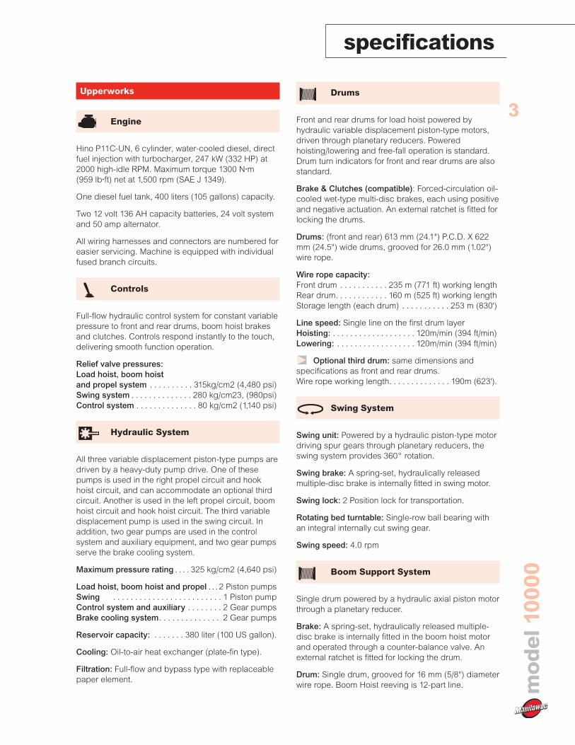
Engine
Hino P11C-UN, 6 cylinder, water-cooled diesel, directfuel injection with turbocharger, 247 kW (332 HP) at2000 high-idle RPM. Maximum torque 1300 N•m(959 lb•ft) net at 1,500 rpm (SAE J 1349).
One diesel fuel tank, 400 liters (105 gallons) capacity.
Two 12 volt 136 AH capacity batteries, 24 volt systemand 50 amp alternator.
All wiring harnesses and connectors are numbered foreasier servicing. Machine is equipped with individualfused branch circuits.
Controls
Full-flow hydraulic control system for constant variablepressure to front and rear drums, boom hoist brakesand clutches. Controls respond instantly to the touch,delivering smooth function operation.
Relief valve pressures:Load hoist, boom hoistand propel system . . . . . . . . . . 315kg/cm2 (4,480 psi)Swing system . . . . . . . . . . . . . . 280 kg/cm23, (980psi)Control system . . . . . . . . . . . . . . 80 kg/cm2 (1,140 psi)
Hydraulic System
All three variable displacement piston-type pumps aredriven by a heavy-duty pump drive. One of thesepumps is used in the right propel circuit and hookhoist circuit, and can accommodate an optional thirdcircuit. Another is used in the left propel circuit, boomhoist circuit and hook hoist circuit. The third variabledisplacement pump is used in the swing circuit. Inaddition, two gear pumps are used in the controlsystem and auxiliary equipment, and two gear pumpsserve the brake cooling system.
Maximum pressure rating . . . . 325 kg/cm2 (4,640 psi)
Load hoist, boom hoist and propel . . . 2 Piston pumpsSwing . . . . . . . . . . . . . . . . . . . . . . . . . 1 Piston pumpControl system and auxiliary . . . . . . . . 2 Gear pumpsBrake cooling system. . . . . . . . . . . . . . 2 Gear pumps
Reservoir capacity: . . . . . . . 380 liter (100 US gallon).
Cooling: Oil-to-air heat exchanger (plate-fin type).
Filtration: Full-flow and bypass type with replaceablepaper element.
Drums
Front and rear drums for load hoist powered byhydraulic variable displacement piston-type motors,driven through planetary reducers. Poweredhoisting/lowering and free-fall operation is standard.Drum turn indicators for front and rear drums are alsostandard.
Brake & Clutches (compatible): Forced-circulation oil-cooled wet-type multi-disc brakes, each using positiveand negative actuation. An external ratchet is fitted forlocking the drums.
Drums: (front and rear) 613 mm (24.1") P.C.D. X 622mm (24.5") wide drums, grooved for 26.0 mm (1.02")wire rope.
Wire rope capacity:Front drum . . . . . . . . . . . 235 m (771 ft) working lengthRear drum. . . . . . . . . . . . 160 m (525 ft) working lengthStorage length (each drum) . . . . . . . . . . . 253 m (830')
Line speed: Single line on the first drum layerHoisting: . . . . . . . . . . . . . . . . . . . 120m/min (394 ft/min)Lowering: . . . . . . . . . . . . . . . . . . 120m/min (394 ft/min)
Optional third drum: same dimensions andspecifications as front and rear drums.Wire rope working length. . . . . . . . . . . . . . 190m (623').
Swing System
Swing unit: Powered by a hydraulic piston-type motordriving spur gears through planetary reducers, theswing system provides 360° rotation.
Swing brake: A spring-set, hydraulically releasedmultiple-disc brake is internally fitted in swing motor.
Swing lock: 2 Position lock for transportation.
Rotating bed turntable: Single-row ball bearing withan integral internally cut swing gear.
Swing speed: 4.0 rpm
Boom Support System
Single drum powered by a hydraulic axial piston motorthrough a planetary reducer.
Brake: A spring-set, hydraulically released multiple-disc brake is internally fitted in the boom hoist motorand operated through a counter-balance valve. Anexternal ratchet is fitted for locking the drum.
Drum: Single drum, grooved for 16 mm (5/8") diameterwire rope. Boom Hoist reeving is 12-part line.

specificationsm
od
el10
000
4Wire Rope Capacity:Drum 150 m (492 ft) working length.
Line speed: Single line on the first drum layer
Hoisting . . . . . . . . . . . . . . . . . . . . 70m/min (230 ft/min)Lowering . . . . . . . . . . . . . . . . . . . . 70m/min (230 ft/min)
Gantry
This high folding type gantry is fitted with a sheaveframe for boom hoist reeving. Hydraulic lift isstandard. It provides full up, full down positions withlinkage.
Counterweight
Operator’s Cab
Totally enclosed, full vision cab fitted with tinted safetyglass. A fully adjustable, highbacked seat with armrests permits operators to set their ideal workingposition. Side mounted console for auxiliary controlsand instruments. An air conditioner, a signal horn,cigarette lighter, windshield wiper and inspection lampsocket are standard features.
ControlsIn front of operator are the foot pedals for front, rearand third drum (optional) brakes and foot throttlepedal. At operator’s right side are the travel (propel)control levers and the function lock lever. To theoperator’s right front are the boom hoist control lever,front and rear winch control levers and the free-fallselect switches for the front and rear winches anddrum turn indicators (front /rear drum). To theoperator’s left front are the swing control lever andthird drum (optional) control lever. To the operator’sleft are the crawler extend/retract lever and thepositive swing lock. The left hand console containstoggle switches for travel (propel) speed, free-fallhigh/low select, gantry control, crane/clamshell selectswitch and the anti-two-block/boom overhoistswitches. Directly in front of the console are the drumpawl lock for boom, front, rear and third drum
(optional) and the engine ignition key. The swingparking brake and signal horn are mounted on theswing control lever.
GaugesFuel gauge, engine water temperature gauge, hourmeter and tachometer are located on the monitordisplay.
Warning displayAll potential warnings, including battery charge,engine oil pressure, air cleaner, engine oil filter,control main pressure, and hydraulic oil temperaturewill appear on the monitor display when a fault occurs.
Safety deviceFunction lock lever, anti-two-block, boom over hoistlimit switch, boom angle indicator, signal horn, boomhoist drum lock, front and rear drum lock, swing lock,swing alarm (buzzer and lamps), boom backstopsand load moment indicator.
Lowerworks
Carbody
The durable carbody features steel weldedconstruction with extendible axles.
Crawlers
Crawler assemblies can be hydraulically extended forwide-track operation or retracted for transportation.Crawler belt tension adjusted with hydraulic jack andmaintained by shims between idler block and frame.
Crawler driveThe independent hydraulic propel drive is built intoeach crawler side frame. Each drive consists of ahydraulic motor driving a propel sprocket through aplanetary gearbox. The hydraulic motor and gearboxare built into the crawler side frame within the shoewidth. The track rollers are sealed for maintenance-free operation.
Crawler brakesSpring set, hydraulically released, multiple disc-typeparking brakes are built into each propel drive.
Steering mechanismThe hydraulic propel system provides both skidsteering (driving one track only) and counter-rotatingsteering (driving each track in opposite direction) anddifferential track speed.
Crawler shoes66 shoes per side, 914 mm (36") wide each crawler.
Travel speed (High/Low) 1.9/1.2 km/h (1.18/0.75 mph)
UNIT WEIGHT TOTAL WEIGHTQTY. ITEM kg lb kg lb
Carbody2 Each 3 650 8,050 7 300 16,100
Carbody Total 7 300 16,100
Upperworks1 Counterweight A 12 100 26,670 12 100 26,6701 Counterweight B 7 400 16,320 7 400 16,3201 Counterweight C 9,300 20,510 9,300 20,510
Upperworks Total 28 800 63,500
Counterweight TOTAL 36 100 79,600

specifications
mo
del
1000
0
5Attachments
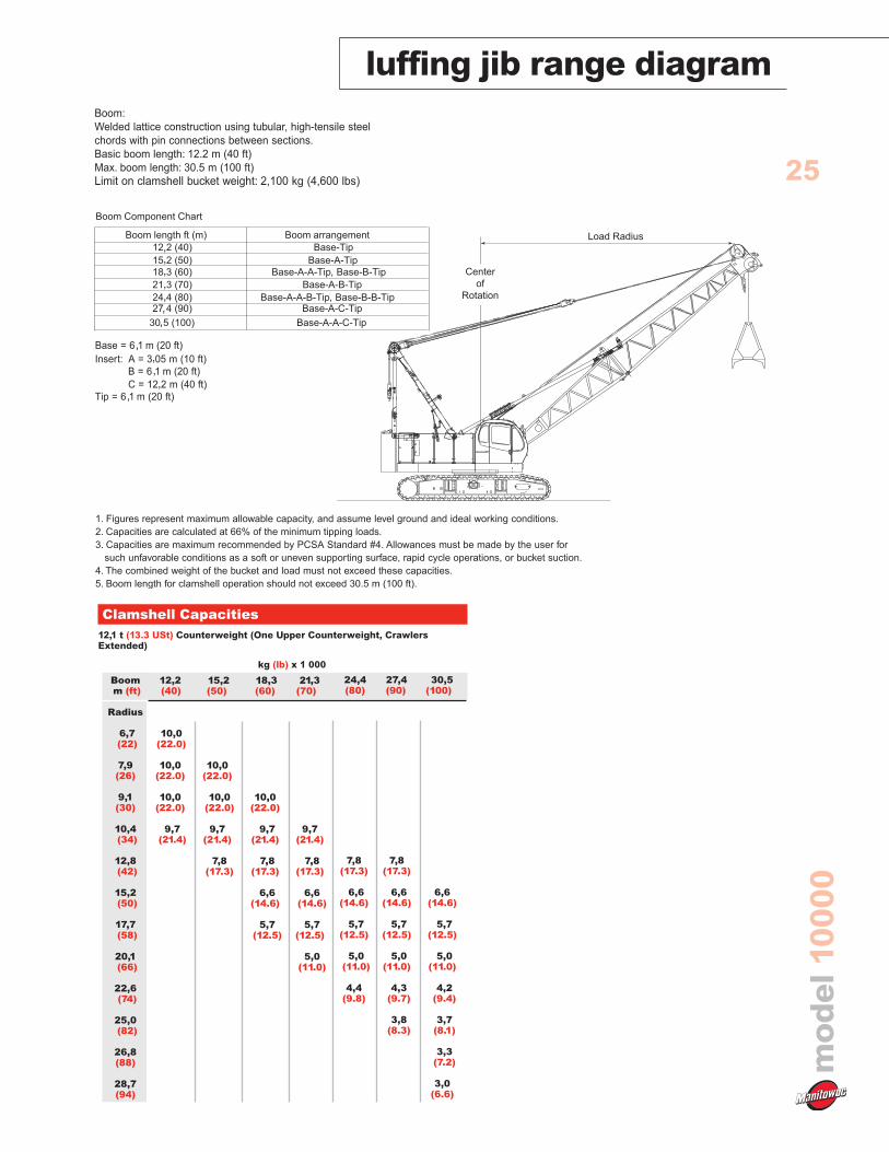
Boom
Welded lattice construction using tubular, high-tensilesteel chords with pin connections between sections.Boom tip is open throat construction. Two idlersheaves and three point sheaves are standard.
Basic boom length 12,2 m (40' ) consists of the boombutt section 5,8 m (19') and boom top section 6,39 m(21').
Optional boom inserts are available to provideextension capabilities. They also have welded latticeconstruction with tubular, high-tension steel chordsand pin connections on each one of 3,0 m (10'), 6,1 m(20'), 12,2 m (40') inserts.
Maximum total length of boom 61,0 m (200').
Fixed Jib
The optional fixed jib employs welded latticeconstruction with tubular, high-tension steel chordswith pin connections between sections.
Basic jib length 9,14 m (30') consists of Jib buttsection 4,57 m(15' ) and jib top section 4,57 m (15').
Optional jib boom inserts of 3,0 m (10'), 6,1 m (20') areavailable for extension capabilities up to 18,3 m (60').
Maximum total length of boom and jib 57,9 m (190') +18,3 m (60') is 76,2 m (250').
Luffing Jib
Optional: Components to make up 16,7 m (55')basic luffing boom including 6,1 m (20') butt, 9,1 m(30') boom special insert (with idler sheave), 1,5 m (5')top, 5,7 m (19') luffing jib butt, boom strut assembly,jib strut assembly, jib stop assembly, strut backstops,backstay pendants with sheaves, mounting parts andLMI Hardware.
Optional: 3,1 m (10'), 6,1 m (20'), and 9,1 m (30')luffing boom inserts. Utilize optional boom inserts tomake up to 35,0 m (115') of luffing boom.
Optional: 15,2 m (50') basic luffing jib assemblyincluding 5,8 m (19') luffing jib butt, 3,0 m (10') luffingjib insert, 6,4 m (21') luffing jib top, 6,4 m (21') frontstrut assembly, 5,3 (17' 5") rear strut assembly, andluffing jib point roller assembly (single sheave) whichis required during erection of the jib. The 6,4 m (21')luffing jib top utilizes the existing boom top from thebase crane.
Maximum 45,7 m (150') jib length for 32,0 m (105')boom length and maximum 30,4 m (100') jib length for
35,0 m (115') boom length.
Note: Luffing jib top and inserts use liftcrane boomtop and inserts. Also, the third drum and wire ropemust be ordered with luffing jib attachment.
Tools and Accessories
A set of tools and accessories are furnished.
Optional Equipment
Optional: Blocks and Hooks each with rollerbearing sheaves grooved for 26.0 mm (1.02") dia. wirerope, and roller bearing swivel with hook latch.
11 t ball hook, 292 kg wedge socket for 26 mm wire rope.(12 USt ball hook, 722 lb wedge socket for 26 mmwire rope.)
35 t hook block, 700 kg with one 622 mm Nominal O.D. roller bearing sheave.(50 USt hook block, 2,311 lb with three 24" Nominal O.D. roller bearing sheaves.)
70 t hook block, 900 kg, three 622 mm Nominal O.D. roller bearing bearing sheaves.(75 USt hook block, 3,820 lb, with four 24" Nominal O.D. roller bearing sheaves.)
90 t hook block, 1 300 kg, with four 622 mm Nominal O.D. roller bearing sheaves.(100 USt hook block, 2,946 lb with four 24" Nominal O.D. roller bearing sheaves.)
Optional: Detachable upper boom point with one575 mm Nominal outer diameter roller bearing steelsheave grooved for 26mm rope for liftcrane.
Travel kitCustom color
Working Weight
Approximately 81,500 kg (179,700 lb) includingupperworks and lowerworks, full uppercounterweights, full carbody counterweights and 12,2m (40') basic boom.
Ground Pressure
Approximately 75.6 kPa (11.0 psi) with basic boomand no load.
Gradeability
With basic boom: 40%.

outline dimensionsm
od
el10
000
6 2.03 m(6' 8")
6.20
m(2
0'4"
)
5.44 m (17' 10")
6.30 m (20' 8")
BasicBoom
12.19 m(40')
1.10 m(3' 7")
R= 4.38 m (14' 5")
3.42 m(11' 3")
1.52
m(4
'11"
)
1.77
m(5
'10"
)
1.12
m(3
'8")
3.61 m (11' 10") Retracted
ROTATION
5.14 m (16' 10") Extended
.39 m (1' 3")
.94 m (3' 1")
1.6 m (5' 3")3.2 m (10' 6")
3.22
m(1
0'7"
)
.91 m (3')

Option
outline dimensions
mo
del
1000
0
7Upperworks x 1
Length 12,19 m 40' 0"Width 3,61 m 11' 10"Height 3,32 m 10' 10"Weight 45 750 kg 100,860 lb
Note: Weight includes base machine, crawler, gantry,maximum hoist and whip lines on drums, boom butt, fullhydraulic fluid reservoir, and one third tank of fuel. en
Upperworks x 1Length 8,44 m 27' 8"Width 3,61 m 11' 10"Height 3,32 m 10' 10"Weight 43 500 kg 95,900 lb
Note: Weight includes base machine, crawler, gantry,maximum hoist and whip lines on drums, full hydraulic fluidreservoir, and one third tank of fuel.
Upperworks without Crawlers x 1Length 12,93 m 42' 5"Width 3,50 m 11' 6"Height 3,06 m 10' 0"Weight 32 250 kg 71,100 lb
Note: Weight includes base machine, crawler, maximum hoistand whip lines on drums, full hydraulic fluid reservoir, andone third tank of fuel.
Crawlers x 2Length 6,30 m 20' 7"Width 0,91 m 3' 0"Height 0,98 m 3' 3"Weight 7 950 kg 17,530 lb
Optional 3rd Drum & Wire Rope x 1Weight 2 660 kg 5,865 lb
Upper Counterweight Series 1 x 1Length 3,20 m 10' 6"Width 0,64 m 2' 1"Height 1,71 m 5' 7"Weight 12 070 kg 27,626 lb
Upper Counterweight Series 2 x 1Length 3,20 m 10' 6"Width 0,52 m 1' 8"Height 1,71 m 5' 7"Weight 7 373 kg 16,254 lb
L
H
L
H
H
L
L
H
W
H
L
L
W
H

Option
outline dimensionsm
od
el10
000
8Upper Counterweight Series 3 x 1
Length 3,20 m 10' 6"Width 0,80 m 2' 7"Height 1,71 m 5' 7"Weight 9 347 kg 20,606 lb
Carbody Counterweight x 2Length 1,67 m 5' 6"Width 1,25 m 4' 1"Height 0,57 m 1' 10"Weight 3 651 kg 8,050 lb
Boom Butt 5,8 m (19') x 1Length 5,17 m 19' 7"Width 1,50 m 4' 11"Height 1,69 m 5' 7"Weight 1 140 kg 2,510 lb
Boom Top 6,4 m (21') x 1Length 6,91 m 22' 8"Width 1,50 m 4' 11"Height 1,48 m 4' 10"Weight 1 170 kg 2,580 lb
Boom Insert 3,0 m (10') x 1, 2Length 3,16 m 10' 5"Width 1,50 m 4'11"Height 1,29 m 4' 3"Weight 310 kg 680 lb
Boom Insert 6,10 (20') x 1, 2Length 6,21 m 20' 4"Width 1,50 m 4' 11"Height 1,29 m 4' 3"Weight 520 kg 1,150 lb
Boom Insert 12,2 m (40') x 1, 2, 3Length 12,31 m 40' 4"Width 1,50 m 4' 11"Height 1,29 m 4' 3"Weight 960 kg 2,120 lb
Note: Use one “A” type insert with lug required for any boomcombinations that require a 12,2 m (40') insert.
Fixed Jib Butt x 1Length 4,81 m 15' 9"Width 0,79 m 2' 7"Height 0,79 m 2' 7"Weight 200 kg 440 lb
L
H
L
H
L
H
W
L
H
W
H
L
L
H
L
H
L
H

Option
outline dimensions
mo
del
1000
0
9Fixed Jib Top x1
Length 4,96 m 16' 3"Width 0,79 m 2' 7"Height 0,79 m 2' 7"Weight 280 kg 620 lb
Fixed Jib Insert 3,0 m (10') x 1Length 3,12 m 10' 3"Width 0,79 m 2' 7"Height 0,79 m 2' 7"Weight 100 kg 220 lb
Fixed Jib Insert 6,1 m (20') x 1Length 6,16 m 20' 3"Width 0,79 m 2' 7"Height 0,79 m 2' 7"Weight 180 kg 400 lb
Fixed Jib Strut x 1Length 3,62 m 11' 11"Width 0,84 m 2' 9"Height 0,62 m 2' 2"Weight 250 kg 550 lb
Luffing Boom Butt x 1Length 6,27 m 20' 7"Width 1,67 m 5' 6"Height 2,06 m 6' 9"Weight 1 540 kg 3,400 lb
body Center Counterweight
Luffing Boom Insert 3,0 m (10') x 1, 2Length 3,16 m 10' 5"Width 1,67 m 5' 6"Height 1,67 m 5' 6"Weight 395 kg 870 lb
Luffing Boom Insert 6,10 m (20') x 1, 2Length 6,21 m 20' 5"Width 1,67 m 5' 6"Height 1,67 m 5' 6"Weight 665 kg 1,470 lb
Luffing Boom Insert 9,14 m (30')x 1, 2, 3
Length 9,26 m 30' 5"Width 1,67 m 5' 6"Height 1,67 m 5' 6"Weight 935 kg 2,060 lb
L
H
L
H
L
H
L
H
L
H
L
H
L
H
L
H

Option
outline dimensionsm
od
el10
000
10Luffing Special Boom Insert9,14 m (30') x 1
Length 9,26 m 30' 5"Width 1,67 m 5' 6"Height 2,41 m 7' 11"Weight 1 160 kg 2,560 lb
Luffing Jib Top x 1Length 6,91 m 22' 8"Width 1,49 m 4' 11"Height 1,48 m 4' 10"Weight 1 170 kg 2,580 lb
Luffing Jib Butt x 1Length 5,97 m 19' 7"Width 1,49 m 4' 11"Height 1,32 m 4' 4"Weight 863 kg 1,900 lb
Luffing Jib Insert 3,0 m (10') x 1, 2Length 3,16 m 10' 5"Width 1,49 m 4' 11"Height 1,29 m 4' 3"Weight 310 kg 685 lb
Luffing Jib Insert 6,10 m (20') x 1, 2Length 6,21 m 20' 5"Width 1,49 m 4' 11"Height 1,29 m 4' 3"Weight 520 kg 1,150 lb
Luffing Jib Insert 12,2 m (40') x 1, 2, 3Length 12,31 m 40' 4"Width 1,49 m 4' 11"Height 1,29 m 4' 3"Weight 960kg 2,120 lb
Luffing Jib Point Roller Assembly x 1
Length 1,01 m 3' 4Width 0,89 m 2' 11"Height 0,91 m 3' 0"Weight 380 kg 840 lb
Luffing Boom Top Assembly(Shipping Style) x 1
Length 8,19 m 26' 10"Width 1,98 m 6' 6"Height 2,65 m 8' 8"Weight 3 500 kg 7,720 lb
L
H
L
H
L
H
L
H
L
H
L
H
L
H
L
H

11
mo
del
1000
0
crane assembly
Sheave Frame
Upper Equalizer
Lower Equalizer
Crawler Frame
Pad
Hook Block
1 Sheave
(Supplied
Separately)
Gantry
Backstop
Boom Butt
(Extended) (Retracted)
(Removed)
Upper Equalizer
Lower Equalizer
Travel Kit
Lift Cylinder
Link
Gantry
Backstop
CTWT (B)
CTWT (C)
CTWT (A)
CounterweightSelf-Handling
Device
Crawler FrameSelf-Removal
Device(Optional)

mo
del
1000
0
12Line Pull
Rated line pull * Maximum line pull
Front Drum11 400 kgs 20 000 kg
(25,100 lb) (44,100 lbs)
Rear Drum11 400 kg 20 000 kg
(25,100 lb) (44,100 lbs)
Optional 3rd Drum11 400 kg 20 000 kg
(25,100 lb) (44,100 lbs)
* Maximum line pull is not based on wire rope strength.
Wire Rope Specifications
Working Breaking
Diameter Length Strength
Use Specs mm (inch) m (ft) kg (lbs)
Front IWRC C/O
Drum 6 X Fi (29)26,0 (1.02") 235 (771') 54 430 (120,000)
Rear IWRC C/O
Drum 6 X Fi (29)26,0 (1.02") 160 (525') 54 430 (120,000)
BoomIWRC O/O
Hoist6 X WS (31)
16,0 (5/8") 150 (492') 21 410 (47,200)
Drum
Opt.IWRC C/O
Third6 X Fi (29)
26,0 (1.02") 190 (623') 54 430 (120,000)
Drum
Model 10000 Front and Rear Winch
Line Speed m/min (ft/min)
Layer 1 2 3 4 5
0 125 (410) 133 (436) 142 (466) 151 (495) 160 (525)
2 268 (5,000) 124 (406) 132 (434) 141 (463) 150 (492) 159 (522)
4 536 (10,000) 108 (355) 108 (355) 108 (355) 108(355) 108(355)
6 804 (15,000) 72 (237) 72 (237) 72 (237) 72 (237) 72 (237)
9 072 (20,000) 54 (177) 54 (177) 54 (177) 54 (177) 54 (177)
11 340 (25,000) 43 (142) 43 (142) 43 (142) 43 (142) 43 (142)
13 608 (30,000) 36 (118) 36 (118) 36 (119) 38 (126) 41 (133)
15 876 (35,000) 32 (104) 34 (111) 36 (118) 38 (125)
18 144 (40,000) 32 (104) 34 (111)
Line Pull kg (lbs)
Rated Line Pull
Note:Line speeds and line pull based on single line.Line pulls are not based on wire rope strength
winch performance data
13
mo
del
1000
0
load chart notes
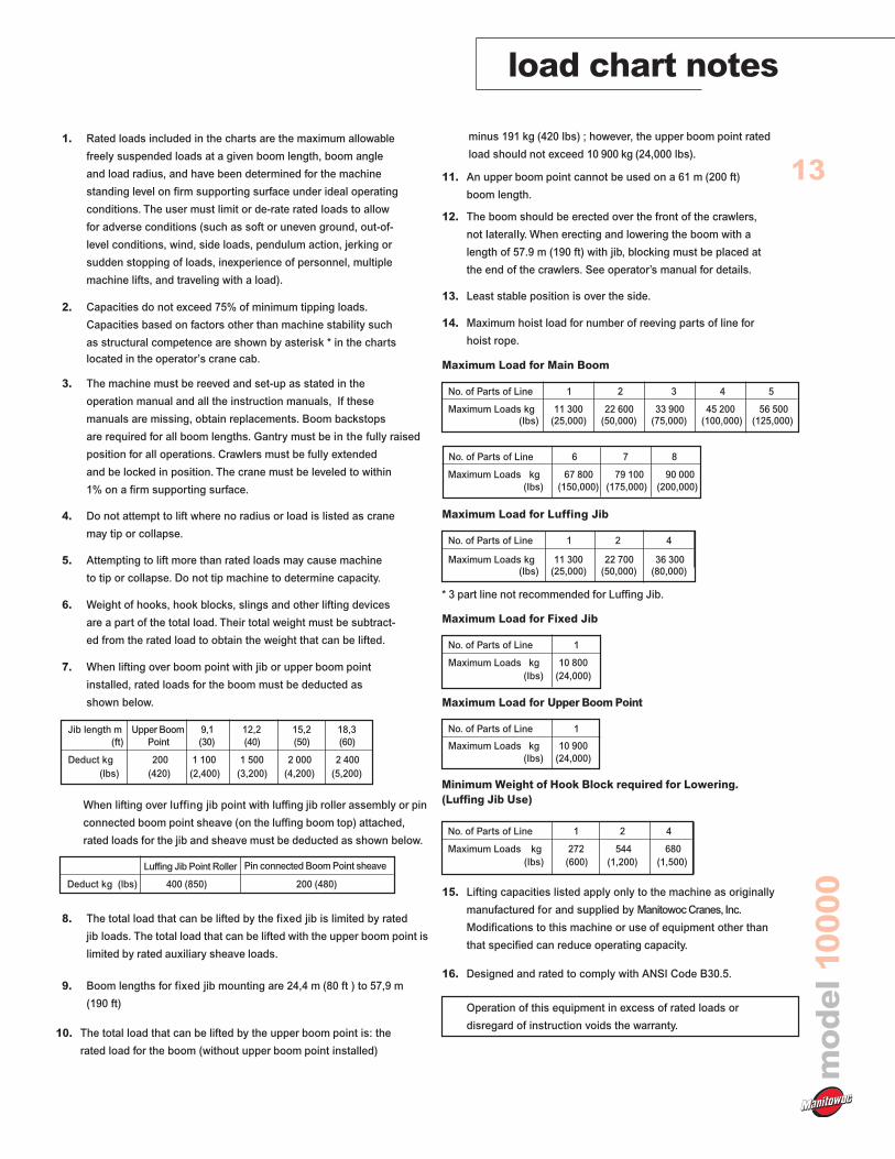
1. Rated loads included in the charts are the maximum allowable
freely suspended loads at a given boom length, boom angle
and load radius, and have been determined for the machine
standing level on firm supporting surface under ideal operating
conditions. The user must limit or de-rate rated loads to allow
for adverse conditions (such as soft or uneven ground, out-of-
level conditions, wind, side loads, pendulum action, jerking or
sudden stopping of loads, inexperience of personnel, multiple
machine lifts, and traveling with a load).
2. Capacities do not exceed 75% of minimum tipping loads.
Capacities based on factors other than machine stability such
as structural competence are shown by asterisk * in the charts
located in the operator’s crane cab.
3. The machine must be reeved and set-up as stated in the
operation manual and all the instruction manuals, If these
manuals are missing, obtain replacements. Boom backstops
are required for all boom lengths. Gantry must be in the fully raised
position for all operations. Crawlers must be fully extended
and be locked in position. The crane must be leveled to within
1% on a firm supporting surface.
4. Do not attempt to lift where no radius or load is listed as crane
may tip or collapse.
5. Attempting to lift more than rated loads may cause machine
to tip or collapse. Do not tip machine to determine capacity.
6. Weight of hooks, hook blocks, slings and other lifting devices
are a part of the total load. Their total weight must be subtract-
ed from the rated load to obtain the weight that can be lifted.
7. When lifting over boom point with jib or upper boom point
installed, rated loads for the boom must be deducted as
shown below.
Jib length m Upper Boom 9,1 12,2 15,2 18,3
(ft) Point (30) (40) (50) (60)
Deduct kg 200 1 100 1 500 2 000 2 400
(lbs) (420) (2,400) (3,200) (4,200) (5,200)
8. The total load that can be lifted by the fixed jib is limited by rated
jib loads. The total load that can be lifted with the upper boom point is
limited by rated auxiliary sheave loads.
9. Boom lengths for fixed jib mounting are 24,4 m (80 ft ) to 57,9 m
(190 ft)
10. The total load that can be lifted by the upper boom point is: the
rated load for the boom (without upper boom point installed)
minus 191 kg (420 lbs) ; however, the upper boom point rated
load should not exceed 10 900 kg (24,000 lbs).
11. An upper boom point cannot be used on a 61 m (200 ft)
boom length.
12. The boom should be erected over the front of the crawlers,
* 3 part line not recommended for Luffing Jib.
not IateraIIy. When erecting and lowering the boom with a
length of 57.9 m (190 ft) with jib, blocking must be placed at
the end of the crawlers. See operator’s manual for details.
13. Least stable position is over the side.
14. Maximum hoist load for number of reeving parts of line for
hoist rope.
Maximum Load for Main Boom
No. of Parts of Line 1 2 3 4 5
Maximum Loads kg 11 300 22 600 33 900 45 200 56 500(Ibs) (25,000) (50,000) (75,000) (100,000) (125,000)
Maximum Loads kg 11 300 22 700 36 300(Ibs) (25,000) (50,000) (80,000)
(Ibs) (24,000)
No. of Parts of Line 6 7 8
Maximum Loads kg 67 800 79 100 90 000
(Ibs) (150,000) (175,000) (200,000)
Maximum Load for Fixed Jib
No. of Parts of Line 1
Maximum Loads kg 10 800
(Ibs) (24,000)
Maximum Loads kg 10 900
Maximum Load for Upper Boom Point
No. of Parts of Line 1
15. Lifting capacities listed apply only to the machine as originally
manufactured for and supplied by Manitowoc Cranes, Inc.
Modifications to this machine or use of equipment other than
that specified can reduce operating capacity.
16. Designed and rated to comply with ANSI Code B30.5.
Operation of this equipment in excess of rated loads or
disregard of instruction voids the warranty.
Maximum Load for Luffing Jib
No. of Parts of Line 1 2 4
Luffing Jib Point Roller Pin connected Boom Point sheave
Deduct kg (lbs) 400 (850) 200 (480)
When lifting over luffing jib point with luffing jib roller assembly or pin
connected boom point sheave (on the luffing boom top) attached,
rated loads for the jib and sheave must be deducted as shown below.
Minimum Weight of Hook Block required for Lowering.
(Luffing Jib Use)
No. of Parts of Line 1 2 4
Maximum Loads kg 272 544 680
(Ibs) (600) (1,200) (1,500)

boom combinationsm
od
el10
000
14
10000
Boom Lengthm (ft)
12,2 (40)
15,2 (50)
18,3 (60)
21,3 (70)
24,4 (80)
27,4 (90)
30,5 (100)
33,5 (110)
36,6 (120)
39,6 (130)
42,7 (140)
45,7 (150)
48,8 (160)
51,8 (170)
54,9 (180)
57,9 (190)
61,0 (200)
3,1 m(10 ft)
–
1
2
1
2
1
2
1
2
1
2
1
2
1
2
1
2
6,1 m(20 ft)
–
–
–
1
1
2
2
1
1
2
2
1
1
2
2
1
1
12,2 m(40 ft)
–
–
–
–
–
–
–
1*
1*
1*
1*
2*
2*
2*
2*
3*
3*
Boom Inserts
Model 10000 Main Boom
61,0 m (200 ft)
5,8 m (19 ft)0Boom Butt
12,2 m (40 ft)Boom Insert
6,1 m (20 ft)Boom Insert
3,0 m (10 ft)Boom Insert
12,2 m (40 ft)Boom Insert
12,2 m (40 ft)Boom Insert
6,4 m (21 ft)No. 10000Boom Top
Model 10000Main Boom
61,0 m (200 ft)
10000
Model 10000Fixed Jib onMain Boom
76,2 m (250 ft)
3,1 m (10 ft)Jib Insert
4,6 m (15 ft)Jib Top
4,6 m (15 ft)Jib Butt
Model 10000Fixed Jib
18,3 m (60 ft)
3,0 m (10 ft)Boom Insert
12,2 m (40 ft)Boom Insert
6,1 m (20 ft)Boom Insert
12,2 m (40 ft)Boom Insert
12,2 m (40 ft)Boom Insert
6,4 m (21 ft)Boom Top
*Note: One 40 ft. (12,20 m) boom insert withlug 40A (12,20 m) is required for fixed jib.When no jib is installed a 40 ft (12,20 m) boomcan be used instead of 40A (12,20 m).
6,1 m (20 ft)Jib Insert
6,1m(20 ft)
–
-
1
1
Jib Lengthm (ft)
9,1 (30)
12,2 (40)
15,2 (50)
18,3 (60)
3,1m(10 ft)
–
1
-
1
No. 10000 Fixed Jib Combinations
Fixed Jib Inserts
5,8 m (19 ft)Boom Butt
Model 10000Main Boom
57,9 m (190 ft)
3,0 m (10 ft)Boom Insert
No. 10000 Heavy-Lift Boom Combinations
boom combinations
mo
del
1000
0
15
10000
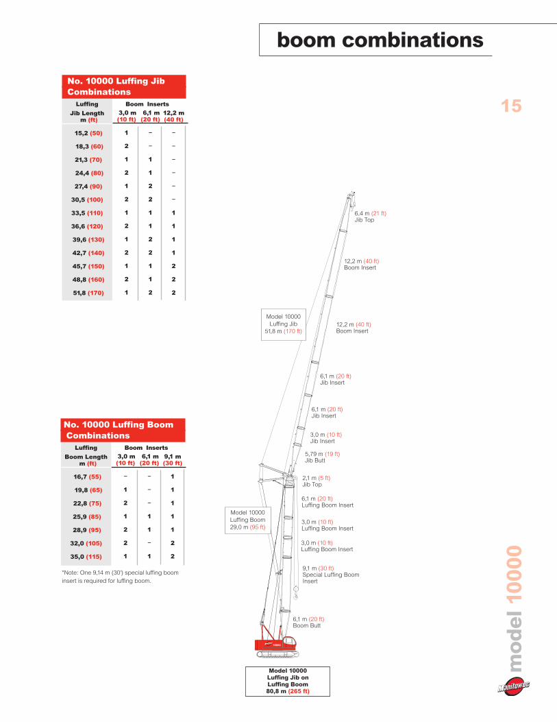
Model 10000Luffing Jib onLuffing Boom80,8 m (265 ft)
3,0 m (10 ft)Jib Insert
2,1 m (5 ft)Jib Top
5,79 m (19 ft)Jib Butt
Model 10000Luffing Jib
51,8 m (170 ft)
9,1 m (30 ft)Special Luffing BoomInsert
3,0 m (10 ft)Luffing Boom Insert
12,2 m (40 ft)Boom Insert
Model 10000Luffing Boom29,0 m (95 ft)
6,1 m (20 ft)Jib Insert
6,1 m (20 ft)Boom Butt
6,1 m (20 ft)Luffing Boom Insert
6,4 m (21 ft)Jib Top
12,2 m (40 ft)Boom Insert
6,1 m (20 ft)Jib Insert
Luffing
Jib Lengthm (ft)
15,2 (50)
18,3 (60)
21,3 (70)
24,4 (80)
27,4 (90)
30,5 (100)
33,5 (110)
36,6 (120)
39,6 (130)
42,7 (140)
45,7 (150)
48,8 (160)
51,8 (170)
3,0 m(10 ft)
1
2
1
2
1
2
1
2
1
2
1
2
1
6,1 m(20 ft)
–
–
1
1
2
2
1
1
2
2
1
1
2
12,2 m(40 ft)
–
–
–
–
–
–
1
1
1
1
2
2
2
Boom Inserts
No. 10000 Luffing JibCombinations
Luffing
Boom Lengthm (ft)
16,7 (55)
19,8 (65)
22,8 (75)
25,9 (85)
28,9 (95)
32,0 (105)
35,0 (115)
3,0 m(10 ft)
–
1
2
1
2
2
1
6,1 m(20 ft)
–
–
–
1
1
–
1
9,1 m(30 ft)
1
1
1
1
1
2
2
Boom Inserts
No. 10000 Luffing BoomCombinations
*Note: One 9,14 m (30') special luffing boominsert is required for luffing boom.
3,0 m (10 ft)Luffing Boom Insert

heavy-lift boom range diagramm
od
el10
000
16
10000
ROTATION
TAILSWING
4,38 m (14' 5")
1,75 m (5' 9")
1,10 m (3' 7")
HE
IGH
TA
BO
VE
GR
OU
ND
m(f
t)
(40) 12,2
(200) 61,0
(180) 54,9
(160) 48,8
(140) 42,7
(120) 36,6
(100) 30,5
(80) 24,4
(60) 18,3
(30) 9,1
(190) 57,9
(210) 64,0
(170) 51,8
(150) 45,7
(130) 39,6
(110) 33,5
(90) 27,4
(70) 21,3
(50) 15,2
DISTANCE FROM CENTERLINE OF ROTATION m (ft)
48,8 (160)
54,9 (180)
42,7 (140)
36,6 (120)
30,5 (100)
24,4 (80)
18,3 (60)
12,2 (40)
82 0
70 0
80 0
60 0
50 0
40 0
30 0
20 0
36,6 m(120')
39,6 m(130')
42,7 m(140')
45,7 m(150')
33,5 m(110')
30,5 m(100')
27,4 m(90')
24,4 m(80')
21,4 m(70')
18,3 m(60')
15,3 m(50')
12,2 m(40')
48,8 m(160')
51,8 m(170')
54,9 m(180')
57,9 m(190')
61,0 m(200')
No. 10000 Main Boom
heavy-lift load charts
mo
del
1000
0
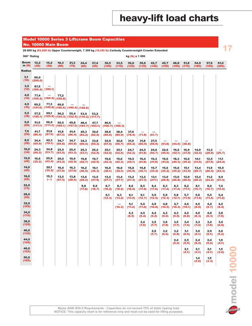
Meets ANSI B30.5 Requirements - Capacities do not exceed 75% of static tipping load.NOTICE: This capacity chart is for reference only and must not be used for lifting purposes.
17
Boomm (ft)
Radius
3,1(10)
3,5(12)
4,0(14)
4,5(16)
5,5(18)
6,0(20)
7,0(24)
8,0(28)
10,0(34)
12,0(40)
14,0(45)
16,0(55)
22,0(75)
28,0(95)
32,0(105)
34,0(115)
38,0(125)
40,0(135)
44,0(145)
46,0(155)
50,0(165)
12,2 (40)
90,0(200.0)
87,5(185.4)
77,4(160.2)
69,2(141.0)
57,2(126.1)
51,5(111.1)
41,7(86.4)
34,4(69.0)
24,3(50.2)
16,6(35.2)
15,2(50)
—(185.1)
—(160.0)
77,3(140.8)
69,1(125.8)
56,9(111.3)
51,6(87.5)
42,3(70.1)
34,8(53.7)
25,6(43.4)
20,1(35.2)
15,3(—)
18,3(60)
77,2(159.8)
69,0(140.6)
56,2(124.3)
50,5(109.1)
41,8(87.3)
34,7(69.8)
25,5(53.5)
20,0(43.2)
16,4(37.0)
13,5(27.3)
24,4(80)
—(138.6)
53,9(119.2)
48,4(104.7)
40,3(84.2)
34,3(69.4)
25,3(53.1)
19,8(42.7)
16,2(36.5)
13,6(28.2)
8,8(17.8)
36,6(120)
37,6(78.4)
31,9(65.2)
24,7(52.2)
19,5(42.1)
15,8(35.9)
13,2(27.3)
8,6(18.0)
6,1(13.0)
5,1(11.2)
4,3(8.5)
Model 10000 Series 3 Liftcrane Boom CapacitiesNo. 10000 Main Boom 28 800 kg (63,500 lb) Upper Counterweight, 7 300 kg (16,100 lb) Carbody Counterweight Crawler Extended
360° Rating kg (lb) x 1 000
48,8(160)
—(44.0)
19,2(42.1)
18,3(40.3)
15,6(35.2)
13,0(26.8)
8,3(17.4)
5,8(12.1)
4,7(10.3)
4,3(9.0)
3,5(7.7)
3,2(6.8)
2,4(5.2)
54,9(180)
14,9(32.6)
14,1(31.0)
13,4(29.7)
12,4(26.2)
8,1(16.7)
5,6(11.6)
4,5(9.9)
4,0(8.3)
3,3(7.2)
3,0(6.1)
2,4(5.2)
2,1(4.1)
1,4(3.0)
57,9(190)
13,3(28.8)
12,5(27.5)
11,9(26.4)
11,2(24.2)
8,0(16.7)
5,5(11.4)
4,4(9.7)
4,0(8.3)
3,2(7.0)
2,9(6.1)
2,4(5.2)
2,1(4.1)
1,5(3.3)
61,0(200)
—(25.7)
11,1(24.4)
10,5(23.3)
9,9(21.3)
7,4(15.6)
5,4(11.2)
4,2(9.4)
3,8(7.9)
3,0(6.6)
2,6(5.2)
1,9(4.1)
1,5(3.0)
51,8 (170)
—(38.8)
16,9(37.0)
16,0(35.2)
15,1(33.9)
12,9(26.6)
8,2(17.1)
5,7(11.9)
4,6(10.1)
4,2(8.8)
3,4(7.4)
3,1(6.6)
2,5(5.5)
2,1(4.1)
21,3(70)
—(140.4)
55,4(122.5)
49,8(107.5)
41,4(86.4)
34,7(69.8)
25,4(53.3)
19,9(42.9)
16,3(37.0)
13,8(28.6)
27,4(90)
53,2(117.7)
47,7(103.1)
39,6(82.6)
33,8(69.2)
25,2(52.9)
19,7(42.5)
16,1(36.3)
13,5(27.9)
8,9(18.7)
33,5(110)
—(100.3)
38,4(80.0)
32,6(66.7)
25,1(52.6)
19,6(42.3)
16,0(36.1)
13,4(27.7)
8,7(18.2)
6,3(13.2)
—(10.3)
42,7(140)
—(61.7)
27,5(59.9)
24,0(50.7)
19,3(41.6)
15,7(35.4)
13,1(27.1)
8,4(17.6)
5,9(12.5)
4,9(10.8)
4,4(9.2)
3,5(7.7)
2,9(5.7)
39,6(130)
—(71.8)
31,8(65.0)
24,5(51.8)
19,4(41.8)
15,8(35.7)
13,2(27.3)
8,5(17.8)
6,1(12.7)
5,0(11.0)
4,5(9.4)
3,2(7.0)
45,7(150)
—(51.8)
22,6(49.6)
19,0(41.2)
15,6(35.2)
13,0(26.8)
8,3(17.4)
5,9(12.3)
4,8(10.5)
4,3(9.0)
3,6(7.9)
3,2(6.6)
30,5(100)
46,6(100.7)
38,6(80.6)
32,9(67.4)
25,1(52.6)
19,6(42.3)
16,0(36.1)
13,4(27.7)
8,7(18.2)
6,1(12.3)

fixed jib range diagram
18
mo
del
1000
0
TAILSWING
4,38(14' 5")
1,75 m(5' 9")
1,10 m(3' 7")
ROTATION
TAILSWING 1,75 m(5' 9")
1,10 m(3' 7")
HE
IGH
TA
BO
VE
GR
OU
ND
m(f
t)
(200) 61,0
(220) 67,1
(240) 73,2
(260) 79,2
(180) 54,9
(160) 48,8
(140) 42,7
(120) 36,6
(100) 30,5
(80) 24,4
(60) 18,3
(190) 57,9
(210) 64,0
(230) 70,1
(250) 76,2
(170) 51,8
(150) 45,7
(130) 39,6
(110) 33,5
(90) 27,4
(70) 21,3
DISTANCE FROM CENTERLINE OF ROTATION m (ft)
48,8(160)
54,9(180)
42,7(140)
36,6(120)
30,5(100)
24,4(80)
18,3(60)
12,2(40)
10000
(30) 9,1
(50) 15,2
(40) 12,2
80 0
82 0
61,0(200)
64,0(210)
67.1(220)
70.1(230)
57,9(190)
54,9(180)
51,8(170)
48,8(160)
45,7(150)
42,7(140)
39,6(130)
36,6(120)
33,5(110)
70 0
60 0
50 0
40 0
73.2(240)
30 0
10 0
30 0
18,3(60)
15,2(50)
12,2(40)
9,1(30)
No. 10000 Fixed Jib on Main Boom

fixed jib load charts
19
mo
del
1000
0
Meets ANSI B30.5 Requirements - Capacities do not exceed 75% of static tipping load.NOTICE: This capacity chart is for reference only and must not be used for lifting purposes.
Model 10000 Series 3 Liftcrane Jib CapacitiesNo. 10000 Fixed Jib on Main Boom28 800 kg (63,500 lb) Upper Counterweight, 7 300 kg (16,100 lb) Carbody Counterweight Crawler Extended
360° Rating kg (lb) x 1 000
10˚ Offset 30˚ Offset
24,4(80)
10,8(24.0)
10,8(24.0)
10,8(24.0)
10,8(24.0)
8,0(17.3)
5,9(12.8)
30,5(100)
10,8(24.0)
10,8(24.0)
10,8(24.0)
7,8(16.8)
5,7(12.2)
4,5(—)
39,6(130)
10,8(24.0)
10,8(24.0)
10,8(24.0)
7,4(16.1)
5,3(11.5)
3,9(8.5)
2,9(6.1)
2,7(—)
Boomm (ft)
Radius
10,0(30)
12,0(40)
14,0(50)
18,0(60)
24,0(80)
30,0(100)
36,0(120)
42,0(140)
44,0(150)
48,0(160)
52,0(170)
Jib
9,1
m(3
0ft
)
48,8(160)
10,8(24.0)
10,7(23.7)
7,2(15.5)
5,0(10.9)
3,7(7.9)
2,7(5.8)
2,4(4.7)
1,7(3.6)
1,4(—)
57,9(190)
—(19.4)
8,4(18.6)
6,9(14.8)
4,7(10.2)
3,3(7.2)
2,3(4.8)
2,0(3.9)
1,5(—)
24,4(80)
9,5(21.0)
9,2(19.5)
8,0(17.5)
6,7(14.8)
30,5(100)
9,4(20.6)
8,5(18.6)
7,3(15.9)
6,0(—)
39,6(130)
—(21.0)
9,2(20.1)
7,6(16.6)
5,4(11.8)
Boomm (ft)
Radius
10,0(30)
12,0(40)
14,0(50)
18,0(60)
24,0(80)
30,0(100)
36,0(120)
42,0(140)
44,0(150)
48,0(160)
52,0(170)
Jib
9,1
m(3
0ft
)
48,8(160)
9,5(21.0)
7,4(16.0)
5,2(11.2)
3,8(8.2)
57,9(190)
8,2(18.2)
7,2(15.5)
4,9(10.6)
3,5(7.5)
2,4(5.2)
2,1(4.2)
24,4(80)
10,8(—)
10,8(24.0)
10,8(24.0)
9,5(20.7)
7,2(15.6)
5,8(12.6)
30,5(100)
10,8(—)
10,8(24.0)
10,8(24.0)
10,6(23.2)
7,9(17.0)
5,7(12.4)
4,4(9.4)
39,6(130)
10,8(—)
10,8(24.0)
10,8(24.0)
7,5(16.3)
5,4(11.7)
4,0(8.7)
3,1(6.6)
2,7(5.3)
Boomm (ft)
Radius
10,0(30)
12,0(40)
14,0(50)
18,0(60)
24,0(80)
30,0(100)
36,0(120)
42,0(140)
44,0(150)
48,0(160)
52,0(170)
Jib
12
,2m
(40
ft)
48,8(160)
10,8(24.0)
10,8(24.0)
7,3(15.7)
5,1(11.1)
3,7(8.0)
2,8(5.9)
2,5(5.0)
1,9(4.0)
1,4(3.1)
57,9(190)
8,4(18.5)
7,0(15.1)
4,8(10.4)
3,4(7.3)
2,4(5.0)
2,1(4.1)
1,5(3.2)
24,4(80
6,9(14.4)
6,8(12.9)
5,9(10.9)
5,0(—)
30,5(100)
—(15.1)
6,8(13.6)
6,2(11.6)
5,3(10.3)
4,7(—)
39,6(130)
—(14.5)
6,6(12.5)
5,7(11.1)
5,0(8.9)
4,1(—)
Boomm (ft)
Radius
10,0(30)
12,0(40)
14,0(50)
18,0(60)
24,0(80)
30,0(100)
36,0(120)
42,0(140)
44,0(150)
48,0(160)
52,0(170)
Jib
12
,2m
(40
ft)
48,8(160)
—(15.1)
6,8(13.2)
6,0(11.6)
5,3(8.4)
3,9(6.2)
2,9(—)
57,9(190)
—(13.8)
6,3(11.0)
5,1(7.8)
3,6(5.5)
2,6(4.4)
2,3(—)
1,8(—)

fixed jib load charts
20
mo
del
1000
0
Meets ANSI B30.5 Requirements - Capacities do not exceed 75% of static tipping load.NOTICE: This capacity chart is for reference only and must not be used for lifting purposes.
Model 10000 Series 3 Liftcrane Jib CapacitiesNo. 10000 Fixed Jib on Main Boom28 800 kg (63,500 lb) Upper Counterweight, 7 300 kg (16,100 lb) Carbody Counterweight Crawler Extended
360° Rating kg (lb) x 1 000
10˚ Offset 30˚ Offset
24,4(80)
9,0(20.0)
9,0(20.0)
7,8(17.0)
5,9(12.8)
4,7(10.3)
4,1(—)
30,5(100)
9,0(20.0)
9,0(20.0)
8,6(18.9)
6,6(14.4)
5,3(11.6)
4,4(9.5)
3,5(—)
39,6(130)
9,0(20.0)
9,0(20.0)
7,6(16.5)
5,5(11.8)
4,1(8.8)
3,1(6.7)
2,9(5.8)
2,2(4.6)
Boomm (ft)
Radius
10,0(30)
12,0(40)
14,0(50)
18,0(60)
24,0(80)
30,0(100)
36,0(120)
42,0(140)
44,0(150)
48,0(160)
52,0(170)
Jib
15
,2m
(50
ft)
48,8(160)
9,0(20.0)
7,4(15.9)
5,2(11.2)
3,8(8.2)
2,8(6.1)
2,5(5.2)
2,0(4.3)
1,5(3.4)
57,9(190)
8,1(18.4)
7,1(15.3)
4,9(10.5)
3,5(7.5)
2,4(5.2)
2,1(4.2)
1,6(—)
24,4(80)
4,8(10.4)
4,0(8.7)
3,4(7.6)
30,5(100)
5,0(10.9)
4,2(9.2)
3,7(8.0)
39,6(130)
5,2(11.4)
4,5(9.8)
3,9(8.7)
3,5(7.6)
Boomm (ft)
Radius
10,0(30)
12,0(40)
14,0(50)
18,0(60)
24,0(80)
30,0(100)
36,0(120)
42,0(140)
44,0(150)
48,0(160)
52,0(170)
Jib
15
,2m
(50
ft)
48,8(160)
4,7(10.3)
4,2(9.2)
3,8(8.3)
3,0(6.4)
2,7(5.5)
57,9(190)
4,9(10.7)
4,4(9.6)
3,8(8.1)
2,7(5.7)
2,4(4.7)
1,8(3.8)
24,4(80)
8,1(18.0)
8,1(17.8)
6,8(14.8)
5,1(11.1)
4,0(8.8)
3,4(7.3)
30,5(100)
8,1(18.0)
7,5(16.3)
5,6(12.3)
4,5(9.9)
3,8(8.2)
3,2(7.1)
3,1(—)
39,6(130)
—(18.0)
8,1(18.0)
6,4(14.1)
5,2(11.4)
4,1(8.9)
3,1(6.8)
2,9(6.0)
2,4(5.0)
—(4.0)
Boomm (ft)
Radius
10,0(30)
12,0(40)
14,0(50)
18,0(60)
24,0(80)
30,0(100)
36,0(120)
42,0(140)
44,0(150)
48,0(160)
52,0(170)
Jib
18
,3m
(60
ft)
48,8(160)
8,1(18.0)
7,2(15.6)
5,2(11.3)
3,8(8.3)
2,9(6.1)
2,6(5.3)
2,1(4.4)
1,6(3.6)
57,9(190)
8,1(18.0)
7,2(15.4)
4,9(10.7)
3,5(7.5)
2,4(5.2)
2,1(4.3)
1,6(3.4)
24,4(80)
4,0(8.9)
3,3(7.3)
2,8(6.2)
30,5(100)
3,5(7.7)
3,0(6.6)
2,7(5.9)
39,6(130)
3,7(8.1)
3,2(7.1)
2,9(6.3)
2,6(5.8)
Boomm (ft)
Radius
10,0(30)
12,0(40)
14,0(50)
18,0(60)
24,0(80)
30,0(100)
36,0(120)
42,0(140)
44,0(150)
48,0(160)
52,0(170)
Jib
18
,3m
(60
ft)
48,8(160)
3,9(8.5)
3,4(7.5)
3,1(6.7)
2,8(6.2)
2,7(5.7)
2,3(4.9)
57,9(190)
3,9(8.7)
3,5(7.8)
3,2(7.0)
2,7(5.9)
2,4(4.9)
1,9(4.0)
1,4(3.2)

10000
88 ˚
33,5(110)
30,5(100)
21,3(70)
27,4(90)
24,4(80)
36,6(120)
42,7(140)
39,6(130)
78 ̊73 ̊
83 ̊
68 ̊63 ̊
15,2(50)
18,3(60)
26,0(85)
22,9(75)
19,8(65)
16,7(55)
29,0(95)
35,0(115)
32,0(105)
45,7(150)
48,7(160)
51,8(170)
(40) 12,2
(50) 15,2
(200) 61,0
(210) 64,0
(230) 70,1
(220) 67,1
(240) 73,2
(250) 76,2
(260) 79,3
(190) 57,9
(180) 54,9
(170) 51,8
(160) 48,8
(150) 45,7
(140) 42,7
(130) 39,6
(120) 36,6
(110) 33,5
(100) 30,5
(90) 27,4
(80) 24,4
(70) 21,3
(60) 18,3
45,7 (150)
48,8 (160)
51,8 (170)
54,9 (180)
42,7 (140)
39,6 (130)
36,6 (120)
33,5 (110)
30,5 (100)
27,4 (90)
24,4 (80)
21,3 (70)
18,3 (60)
15,2 (50)
12,2 (40)
9,1 (30)
DISTANCE FROM CENTERLINE ROTATION m (ft)
1,10 m (3' 7") (14' 5")
4,38 m
TAILSWING SERIES B
1,77 m 5' 10"
ROTATION
HE
IGH
TA
BO
VE
GR
OU
ND
m(f
t)
(270) 82,3
20 ̊
30 ˚
40 ̊
50 ̊
60 ̊
70 ̊
75 ̊
(30) 9,1
No. 10000 Luffing Jib on Luffing Boom
luffing jib range diagram
mo
del
1000
0
21

luffing jib load chartsm
od
el10
000
Meets ANSI B30.5 Requirements - Capacities do not exceed 75% of static tipping load.NOTICE: This capacity chart is for reference only and must not be used for lifting purposes.
22
16,7(55)
36,3(80.0)
30,2(67.5)
26,9(58.6)
24,2(49.8)
20,1(43.6)
17,2(38.8)
22,8(75)
30,1(67.3)
26,8(58.3)
24,0(49.5)
20,0(43.4)
17,1(38.5)
28,9(95)
29,9(66.8)
26,5(57.9)
23,8(49.0)
19,8(42.9)
16,9(38.1)
35,0(115)
26,4(57.5)
23,7(48.7)
19,6(42.5)
16,7(37.7)
Boomm (ft)
Radius
6,7(22)
8,0(26)
9,0(30)
10,0(35)
12,0(40)
14,0(45)
18,0(60)
20,0(65)
24,0(80)
28,0(95)
Lu
ffin
gJ
ibL
en
gth
15
,2m
(50
ft)
Model 10000 Series 3 Liftcrane Luffing Jib CapacitiesNo. 10000 Luffing Jib on Luffing Boom
28 800 kg (63,500 lb) Upper Counterweight, 7 300 kg (16,100 lb) Carbody Counterweight Crawler Extended
360° Rating kg (lb) x 1 000
88 ˚ Boom Angle
16,7(55)
23,4(48.9)
19,7(42.9)
16,9(38.1)
12,2(26.2)
10,6(23.6)
8,3(17.9)
6,7(—)
22,8(75)
—(48.9)
19,7(42.5)
16,8(37.9)
12,1(26.0)
10,5(23.6)
8,2(17.6)
6,7(—)
28,9(95)
—(48.4)
19,4(42.2)
16,6(37.4)
12,1(26.0)
10,5(23.4)
8,2(17.6)
6,6(13.9)
35,0(115)
—(48.0)
19,2(41.8)
16,4(37.0)
12,0(25.8)
10,4(23.1)
8,1(17.4)
6,5(13.7)
Boomm (ft)
Radius
6,7(22)
8,0(26)
9,0(30)
10,0(35)
12,0(40)
14,0(45)
18,0(60)
20,0(65)
24,0(80)
28,0(95)
Lu
ffin
gJ
ibL
en
gth
27,
4m
(90
ft)
16,7(55)
16,6(37.5)
11,8(25.6)
7,9(17.0)
7,1(14.6)
5,7(12.3)
5,2(10.6)
3,7(8.2)
22,8(75)
16,4(37.0)
11,8(25.4)
7,9(17.0)
7,0(14.3)
5,7(12.3)
5,2(10.6)
3,6(8.2)
28,9(95)
16,3(36.8)
11,7(25.4)
7,9(17.0)
7,0(14.3)
5,7(12.1)
5,1(10.6)
3,6(7.9)
Boomm (ft)
Radius
10,0(36)
12,0(40)
14,0(45)
18,0(60)
24,0(80)
26,0(90)
30,0(100)
32,0(110)
40,0(130)
44,0(145)
48,0(160)
Lu
ffin
gJ
ibL
en
gth
39
,6m
(13
0ft
)
16,7(55)
11,4(24.5)
7,5(16.1)
6,6(13.4)
5,3(11.5)
4,8(9.7)
3,2(7.3)
2,6(5.7)
22,8(75)
11,4(24.5)
7,5(16.1)
6,6(13.4)
5,3(11.2)
4,7(9.7)
3,2(7.1)
2,6(5.7)
28,9(95)
11,2(24.7)
7,6(16.3)
6,7(13.7)
5,4(11.5)
4,8(9.9)
3,3(7.3)
Boomm (ft)
Radius
10,0(36)
12,0(40)
14,0(45)
18,0(60)
24,0(80)
26,0(90)
30,0(100)
32,0(110)
40,0(130)
44,0(145)
48,0(160)
Lu
ffin
gJ
ibL
en
gth
51,
8m
(17
0ft
)

mo
del
1000
0
luffing jib load charts
Meets ANSI B30.5 Requirements - Capacities do not exceed 75% of static tipping load.NOTICE: This capacity chart is for reference only and must not be used for lifting purposes.
23Model 10000 Series 3 Liftcrane Luffing Jib CapacitiesNo. 10000 Luffing Jib on Luffing Boom
28 800 kg (63,500 lb) Upper Counterweight, 7 300 kg (16,100 lb) Carbody Counterweight Crawler Extended
360° Rating kg (lb) x 1 000
73 ˚ Boom Angle
16,7(55)
—(32.2)
11,7(25.1)
10,2(22.7)
—(20.7)
22,8(75)
11,2(24.3)
9,8(21.8)
8,6(19.8)
28,9(95)
—(22.9)
9,4(20.9)
8,2(19.0)
7,3(15.9)
35,0(115)
7,8(17.6)
6,9(15.0)
Boomm (ft)
Radius
14,0(50)
18,0(60)
20,0(65)
22,0(70)
24,0(80)
28,0(95)
34,0(115)
38,0(125)
44,0(145)
46,0(155)
Lu
ffin
gJ
ibL
en
gth
15
,2m
(50
ft)
16,7(55)
8,6(19.8)
7,6(16.3)
6,2(13.0)
22,8(75)
7,2(15.7)
5,8(12.1)
4,4(—)
28,9(95)
5,4(11.5)
4,1(8.6)
35,0(115)
5,0(10.6)
3,7(7.9)
3,1(6.8)
Boomm (ft)
Radius
14,0(50)
18,0(60)
20,0(65)
22,0(70)
24,0(80)
28,0(95)
34,0(115)
38,0(125)
44,0(145)
46,0(155)
Lu
ffin
gJ
ibL
en
gth
27,
4m
(90
ft)
16,7(55)
5,7(11.9)
4,2(8.8)
3,5(6.8)
2,7(6.0)
22,8(75)
—(11.0)
3,9(8.2)
3,2(6.2)
2,4(5.3)
28,9(95)
—(7.3)
3,6(5.3)
2,9(4.6)
2,1(4.0)
Boomm (ft)
Radius
14,0(50)
18,0(60)
20,0(65)
22,0(70)
24,0(80)
28,0(95)
34,0(115)
38,0(125)
44,0(145)
50,0(165)
Lu
ffin
gJ
ibL
en
gth
39
,6m
(13
0ft
)
16,7(55)
—(7.7)
3,7(5.5)
3,0(4.6)
2,1(4.0)
1,5(—)
22,8(75)
—(6.8)
—(4.9)
2,6(4.0)
1,8(3.3)
28,9(95)
—(4.0)
—(3.3)
2,2(—)
1,5(—)
Boomm (ft)
Radius
14,0(50)
18,0(60)
20,0(65)
22,0(70)
24,0(80)
28,0(95)
34,0(115)
38,0(125)
44,0(145)
50,0(165)
Lu
ffin
gJ
ibL
en
gth
51,
8m
(17
0ft
)

luffing jib load chartsm
od
el10
000
Meets ANSI B30.5 Requirements - Capacities do not exceed 75% of static tipping load.NOTICE: This capacity chart is for reference only and must not be used for lifting purposes.
24Model 10000 Series 3 Liftcrane Luffing Jib CapacitiesNo. 10000 Luffing Jib on Luffing Boom
28 800 kg (63,500 lb) Upper Counterweight, 7 300 kg (16,100 lb) Carbody Counterweight Crawler Extended
360° Rating kg (lb) x 1 000
63˚ Boom Angle
16,7(55)
9,8(21.6)
8,6(18.1)
7,7(—)
22,8(75)
—(16.5)
7,1(14.1)
28,9(95)
—(12.8)
5,3(11.0)
35,0(115)
4,6(9.9)
Boomm (ft)
Radius
14,0(50)
18,0(60)
20,0(65)
22,0(70)
24,0(80)
28,0(95)
34,0(115)
38,0(125)
44,0(145)
46,0(155)
Lu
ffin
gJ
ibL
en
gth
15
,2m
(50
ft)
16,7(55)
5,7(12.1)
4,3(9.0)
22,8(75)
—(8.2)
3,9(7.1)
3,2(—)
28,9(95)
—(7.1)
3,3(6.0)
2,7(—)
35,0(115)
—(4.9)
2,2(—)
1,6(—)
Boomm (ft)
Radius
14,0(50)
18,0(60)
20,0(65)
22,0(70)
24,0(80)
28,0(95)
34,0(115)
38,0(125)
44,0(145)
46,0(155)
Lu
ffin
gJ
ibL
en
gth
27,
4m
(90
ft)
16,7(55)
3,2(6.8)
2,9(6.0)
2,3(5.1)
2,1(4.4)
22,8(75)
2,4(4.9)
1,9(4.2)
1,7(3.5)
1,5(3.1)
28,9(95)
—(3.7)
1,4(3.1)
Boomm (ft)
Radius
14,0(50)
18,0(60)
20,0(65)
22,0(75)
26,0(85)
28,0(95)
38,0(125)
40,0(135)
44,0(145)
46,0(155)
48,0(160)
Lu
ffin
gJ
ibL
en
gth
39
,6m
(13
0ft
)
16,7(55)
1,8(3.7)
1,5(3.1)
Boomm (ft)
Radius
14,0(50)
18,0(60)
20,0(65)
22,0(75)
26,0(85)
28,0(95)
38,0(125)
40,0(135)
44,0(145)
46,0(155)
48,0(160)
Lu
ffin
gJ
ibL
en
gth
51,
8m
(17
0ft
)
luffing jib range diagram
mo
del
1000
0
25
Clamshell Capacities12,1 t (13.3 USt) Counterweight (One Upper Counterweight, CrawlersExtended)
kg (lb) x 1 000
12,2 (40)
10,0(22.0)
10,0(22.0)
10,0(22.0)
9,7(21.4)
15,2 (50)
10,0(22.0)
10,0(22.0)
9,7(21.4)
7,8(17.3)
18,3 (60)
10,0(22.0)
9,7(21.4)
7,8(17.3)
6,6(14.6)
5,7(12.5)
Boomm (ft)
Radius
6,7(22)
7,9(26)
9,1(30)
10,4(34)
12,8(42)
15,2(50)
17,7(58)
20,1(66)
22,6(74)
25,0(82)
26,8(88)
28,7(94)
21,3 (70)
9,7(21.4)
7,8(17.3)
6,6(14.6)
5,7(12.5)
5,0(11.0)
24,4 (80)
7,8(17.3)
6,6(14.6)
5,7(12.5)
5,0(11.0)
4,4(9.8)
27,4 (90)
7,8(17.3)
6,6(14.6)
5,7(12.5)
5,0(11.0)
4,3(9.7)
3,8(8.3)
30,5 (100)
6,6(14.6)
5,7(12.5)
5,0(11.0)
4,2(9.4)
3,7(8.1)
3,3(7.2)
3,0(6.6)
Notes
26
mo
del
1000
0

Notes
27
mo
del
1000
0

AmericasUSA
Manitowoc Crane CARE2401 S. 30th Street,Manitowoc, WI 54220 USA Tel: + 1 920 684 6621Fax: + 1 920 683 6278
Manitowoc Crane CARE1565 Buchanan Trail East,Shady Grove, PA 17256 USATel: + 1 717 597 8121Fax: + 1 717 593 5929
Manitowoc Crane CARE16013 West Sardis RoadBauxite, AR 72011 USATel: + 1 501 557 5800Fax: + 1 501 557 5029
Brazil
Manitowoc Crane CAREEdificio: Itaim Office TowerRua Gomes de Carvalho, 1581 - 2 andar cj 205 / 206Vila Olimpia - SP - Cep: 04547 - 006Brazil Tel: + 55 11 3841 2741Fax: + 55 11 3841 2740
Mexico
Manitowoc Crane CAREMiravalle Center, piso PB,Suite 106 Calz San Pedro250 Nte. Monterrey,Nuevo Leon, MexicoTel: + 5281 8124 0128Fax: + 5281 8124 0129
Europe - Middle East -AfricaUnited Kingdom
Manitowoc Crane CAREAkeler House, 1 Emperor WayDoxford International Business ParkSunderland, England SR3 3XRTel: + 44 191 565 6281Fax: + 44 191 515 7475
France
Manitowoc Crane CARE16 chaussee jules-Cesar,95523 Cergy Pontoise, FranceTel: + 33 130 313 150Fax: + 33 130 386 085
Manitowoc Crane CAREZ.A. Les Pivolles - 5 rue De Catalogne, 69153 DecinesCharpieu Cedex, FranceTel: + 33 4 72 81 50 00Fax: + 33 4 72 81 50 10
Germany
Manitowoc Crane CAREIndustriegelände West 26389 WilhelmshavenPostfach 1853, GermanyTel: + 49 4421 294 454Fax: + 49 4421 294 244
Manitowoc Crane CARECarl-Leverkus-Str. 1440764 Langenfeld, GermanyTel: + 49 2173 8909 0Fax: + 49 21738909 30
Italy
Manitowoc Crane CAREVia delle Fabbriche, 412060 Niella Tanaro, ItalyTel: + 39 174 226 611Fax: + 39 174 226 667
Netherlands
Manitowoc Crane CAREVeilingkade 154815 HC BredaTel: + 31 76 5783999Fax: + 31 76 5783978
Portugal
Manitowoc Crane CARERua da Serra (EN 105/2)Apartado 31174449-908 Alfena, PortugalTel: + 35 1229 698 840Fax: + 35 1229 698 848
United Arab Emirates(UAE)
Manitowoc Crane CAREP.O. Box 75314Villa 354, Road 13DAl Quoz, DubaiTel: + 97 143 381 861Fax: + 97 143 382 343
Asia - PacificSingapore
Manitowoc Crane CARE4 Kwong Min Road Singapore, 628707 SingaporeTel: + 65 626 41188Fax: + 65 686 24040 (Sales/Admin)
+ 65 686 24142 (Parts/Service)
China
Manitowoc Crane CARENo. 55 East Zhen Bei RoadSouth District ZhangjiagangEconomic Development ZoneZhangiagang, Jiangsu215618 PR ChinaTel: + 86 512 5691 5000Fax: + 86 512 5691 5015
Manitowoc Crane CARERM. F. 22F Cross region Plaza899 Lingling RoadShanghai, 200030, PR ChinaTel: + 86 21 5486 1515Fax: + 86 21 5486 3565
Manitowoc Crane CARERM 1201-1205, #933 Zhongshan WestRoadHongqiao Silver TowerShanghai 200051, PR ChinaTel: + 86 21 5111 3579Fax: + 86 21 5111 3578
Australia
Manitowoc Crane CARE2/22 Disney Avenue, East KeilorVIC 3033 AustraliaTel: + 61 03 9336 1300Fax: + 61 03 9336 1322
Manitowoc Crane CARE142 Magowar RoadGirraween NSW 2145 AustraliaTel: + 61 02 9896 4433Fax: + 61 02 9896 3122
Korea
Manitowoc Crane CARERM 301 Gugu Building 145-18Samsung-Dong, Kangnam-KuSeoul 135-878 KoreaTel: + 82 2 508 3361Fax: + 82 2 508 3365
Phillipines
Manitowoc Crane CARE
G/F Southwest Centre BuildingCorner Makiling StreetSouthwest Superhighway,Palanan, Makati City1235 PhillipinesTel: + 632 844 9437Fax: + 632 844 4712
www.manitowoccranecare.com
PRODUCT IMPROVEMENTS MAY CHANGE SPECIFICATIONS ©2006 MANITOWOC 0806-10000-PG-US-E