· proof test 1.96 to 2.45 n monitor type dual 4.1 inch tft color lcd monitors magnification 125...
TRANSCRIPT

www.FusionSplicer.Fujikura.com
SPECIALTY FUSION SPLICING SYSTEMS
ARCMaster® FSM-100M/ P | ARCMaster® FSM-100M+/ P+
LZM-100 LAZERMaster™


www.FusionSplicer.Fujikura.com
FSM-100M and FSM-100P Fusion Splicers Whether splicing similar fiber types or double clad LDF fibers for high power lasers, the ARCMaster series splicers provide multiple solutions for
diverse production needs. With State of the ARC™ technology, the ARCMaster sets the standard for fusion s plicing with a multitude of new
features designed to make splicing easier.
The patent-pending “split V-groove” fiber clamping system accommodates optical fiber ranges from 60 to 500 μm for cladding or 125 to
2000 μm for coating without changing V-grooves. The “Plasma Zone” fiber positioning system incorporates multiple fiber and electrode
positioning techniques to provide unprecedented versatility for splicing LDF, heat sensitive or small diameter fibers.
With a new fiber imaging technology, Interrelation Profile Alignment (IPA), alignment and splic ing capabilities are possible with a variety of
PM fiber type. Longer fiber tapering application is possible with Fujikura’s Sweep Arc technology. Incorporating PAS (cold fiber image) and WSI
(warm image) technologies, the optical analysis system provides a number of advanced features including improved loss estimation capabilities,
fiber image performance with both LDF, small or heat sensitive fibers.
Users can program multi-step glass processing operations either in the machine or from a PC. These include non-splicing operations such as
generating tapers or lenses. Dual LCD monitors provide enhanced data and graphical information that is user -selectable during each stage of the
splicing process. Both units are designed with the needs for production in mind and are suitable for the most popular production workstations.
Features: FSM-100M and FSM-100P
• Split V-groove clamping system • “Plasma Zone” fiber positioning • PAS and WSI • New IPA alignment method for PM fibers • Enhanced sweep arc technology • Zero degree fiber handling for LDF • Special functions for glass processing capability • Fiber profile memory function • New arc calibration technology • Short cleave length capability • Fast and accurate PANDA splice mode • Ergonomic, production friendly design • User selectable display on dual LCD monitors
FSM-100M+ and FSM-100P+ Fusion Splicers The FSM-100M+ and FSM-100P+ specialty fusion splicers provide advanced capabilities suitable for fiber lasers, sensors, research and development and the medical field. New capabilities include an innovative “end-view” fiber observation system, XLDF (Extra Large Diameter Fiber) splicing capability using “Plasma Zone Path Modulation,” enhanced sweep arc technology and other features for glass processing and fiber tapering, and patented split V-groove clamping system. With State of the ARC™ technology, the ARCMaster series of fusion splicers sets a new standard for fusion splicing, providing the ultimate in performance and flexibility.
Features: FSM-100M+and FSM-100P+ have all of the features of the 100 M and P, and the following:
• End-view observation system for alignment of non-circular, “holey” and other exotic fibers • XLDF (Extra Large Diameter Fiber) splicing capability up to 1200 µm diameter fiber • Patented “split V-groove” clamping system covers a range from 60 to 2000 µm • Advanced “Plasma-Zone” control methods to optimize heating for specific fiber types
– Motorized electrodes to change electrode gap to optimize Plasma Zone shape – Adjustable vertical height to position fiber within Plasma Zone – Electrode oscillation produces “Plasma Zone Path Modulation” for XLDF splicing
• Enhanced ability for fi shaping, glass processing, tapering, etc. – Custom multi-step “Special Functions” programmability – Long-travel sweep arc technology (fiber sweep motion up to 32 mm) – Long-travel left/right Z-drive mechanisms
• Three selectable arc calibration methods – Conventional calibration method for standard fibers – New melt-back method with new parameters for special fibers including XLDF – Real-time calibration by arc brightness observation
(with fiber brightness learning function) • Dual 4.1 inch monitors with user-selectable information display • Extensive PC connectivity functions (software upload, data upload/download, PC control)
FSM-100M+ and FSM-100P+ Specifications
FSM-100M and FSM-100P Specifications
PARAMETER VALUE
Applicable Fiber Silica based Single-mode and Multimode glass fiber: SMF (G.652), MMF (G.651), NZDSF (G.655), EDF, DCF, LDF and PMF, etc.
Fiber Dimension Cladding diameter: 60 to 500 µm; Coating diameter: 100 to 2,000 µm
Cleave Length Glass clamping: 8mm to 10 mm (standard 9mm); Coating clamping: 3mm to 5 mm (standard 4mm)
Typical Splice Loss SMF: 0.03 dB; MMF: 0.02 dB; NZDSF/LDF: 0.05 dB; PMF: 0.06 dB (FSM-100P)
Splicing Time SMF/MMF: 15 seconds; NZDSF/LDF: 25 seconds; PMF (PANDA): 35 to 50 seconds (FSM-100P);
PMF (IPA): 90 to 300 seconds (FSM-100P)
Polarization Cross-Talk PMF (PANDA): -40 dB / 0.6 degree (FSM-100P); PMF (IPA): -32 dB / 1.4 degree (FSM-100P)
Return Loss 60 dB or more
Heating Time FP-03 (40 mm): 30 seconds; FP-03 (60 mm): 35 seconds; Micro sleeves: 55 seconds
Sweep Length ±5 mm
Electrode Life 2,500 Arc Discharges (SMF G.652 splicing at 1 mm gap)
Electrode Gap 1mm to 3 mm
Electrode Offset -0.3mm to +0.1 mm
Proof Test 1.96 N to 2.45 N
Monitor Type Dual 4.1 inch TFT color LCD monitors
Magnification 125 µm: 187 to 300 X, 250 µm: 58 to 300 X, 400 µm: 58 to 93 X
Dimensions 311 mm (W) x 232 mm (D) x 160 mm (H)
Weight FSM-100M: 7.5 kg / FSM-100P: 8.0 kg
Power Supply AC adapter: ADC-15, Input: AC100 to 240 V (50 to 60 Hz)
Operating Conditions Temperature: 0 to 40°C, Humidity: 0 to 95% RH (Non-condensing)
Storage Conditions Temperature: -40 to 80°C, Humidity: 0 to 95% RH (Non-condensing)
VALUE
Applicable Fiber Silica based Single-mode and Multimode glass fiber: SMF (G.652), MMF (G.651), NZDSF (G.655), EDF, DCF, LDF and PMF, etc.
Fiber Dimension Cladding diameter: 60µm to 1,200 µm; Coating diameter: 100µm to 2,000 µm
Cleave Length Glass clamping 8mm to 30 mm (standard 9 mm); Coating clamping 3 to 5 mm (standard 4 mm)
Typical Splice Loss SMF: 0.03 dB; MMF: 0.02 dB; NZDSF/LDF: 0.05 dB; PMF: 0.06 dB(FSM-100P+)
Splicing Time SMF/MMF: 15 seconds; NZDSF/LDF: 25 seconds; PMF (PANDA): 35 to 50 seconds (FSM-100P+); PMF (IPA): 70 to 300 seconds (FSM-100P+)
Polarization Cross-Talk PMF (PANDA): -40 dB / 0.6 degree (FSM-100P+); PMF (IPA): -40 dB / 0.6 degree (FSM-100P+)
Return Loss 60 dB or more
Heating Time FP-03 (40 mm): 30 seconds; FP-03 (60 mm): 35 seconds; Micro sleeves: 55 seconds
Sweep Range ±18 mm
Electrode Life 2,500 Arc Discharges (SMF28 G.652 with 1 mm electrode gap)
Electrode Gap 1mm to 3 mm
Electrode Offset -0.3mm to +0.1 mm
Proof Test 1.96 to 2.45 N
Monitor Type Dual 4.1 inch TFT color LCD monitors
Magnification 125 µm: 187 to 300 X, 250 µm: 3.5 to 300 X, 400 µm: 58 to 93 X, 1000 µm: 3.5 to 7.0 X
Dimensions 470 mm (W) x 232 mm (D) x 160 mm (H)
Weight FSM-100M+: 8.5 kg / FSM-100P+: 9.5 kg
Power Supply AC adapter: ADC-15, Input: AC100 to 240 V (50 to 60 Hz)
Operating Conditions Temperature: 0°C to 40°C, Humidity: 0% to 95% RH (Non-condensing)
Storage Conditions Temperature: -40°C to 80°C, Humidity: 0% to 95% RH (Non-condensing)
FSM-100M
FSM-100P
FSM-100M+
FSM-100P+

Comparison of properties of the FSM-100 series
MODEL 100M 100M+ 100P 100P+
Split V-Groove • • • •
PAS Alignment Technology • • • •
IPA Alignment Technology • •
End View Alignment Technology • •
Plasma Zone Fiber Positioning • • • •
Plasma Zone Path Modulation • •
In the Variable Fiber Layer
Sweep Arc Technology (5 mm) • •
Extended Sweep Arc Technology (18 mm) • •
Glass Fiber Molding Processing • • • •
LDF Splice (60 bis 500 µm) • • • •
XLDF Splice (60 bis 1200 µm) • •
Production Friendly Design • • • •
Improved Splice Loss Estimation • • • •
Zero Degree Fiber Holder Position • • • •
Special Arc Calibration • • • •
Internet Firmware Updates • • • •
USB & GPIB • • • •
FSM-100 Series Fusion Splicers Fujikura’s new specialty splicers FSM-100M and FSM-100P offer a host of innovative technology to address the rapidly expanding splicing needs for factory,
manufacturing, laboratory and R&D applications. These models are introduced as “ARCMaster” splicers due to their unique capabilities to control the
plasma zone of the fusion arc. These capabilities will revolutionize the way users will splice various types of specialty fibers; LDF, low contrast PM, holey
structured, etc.
Fiber end face viewing
Light is directed through coating into the cladding coupled. A lens captures the image projected of the fiber end faces.
For certain types of fibers, such as double-cladded fiber, it is difficult for the light to pass through the coating to the cladding. In this case the provided external light source EVLSO1 can be used to feed the light directly into the cladding.
“Plasma Zone” fiber positioning The FSM-100 series has two electrode positioning techniques in order to provide unprecedented versatility for each specialty fiber.
Electrode Gap
Electrode gap: 1 mm
Electrode gap: 3 mm
V Height Shift
Optimum plasma Zone
1200 µm
Applicable fiber:
• Glass clamp: cladding dia. ø60 to 500 µm
• Coating clamp: coating dia. ø100 to ø2000 µm
www.FusionSplicer.Fujikura.com
Patented “Split V-groove” clamping system The FSM-100 series has the revolutionary design clamp system. - No need to change V-groove or clamp part - Programmable for any fiber or coating size - Reliably “captures” fiber for good alignment

www.FusionSplicer.Fujikura.com
All-in-one computer
SpliceLab PC software
(Ball lens GUI shown)
The LZM-100 LAZERMaster is a glass processing and splicing system that uses a CO2 laser heat source to perform splicing, adiabatic tapering (to create MFAs or pump combiners), lensing, or other glass shaping operations. The high resolution optical analysis system works in conjunction with on-board firmware for fully automatic splicing, tapering and other glass shaping processes.
High precision glass processing is enabled by the intuitive and user- friendly on-board firmware (virtually identical to that of the Fujikura FSM-100 ARCMaster splicers). Operations may also be performed manually and by PC control. A SpliceLab PC control GUI is supplied with the LZM-100 to provide additional features, greater flexibility and finer control. The SpliceLab GUI is pre-installed on the All-in- one computer. Customers can also create proprietary PC control algorithms using a complete set of PC control commands.
LZM-100
Keyboard tray
Rugged Aluminum
Work Station with
heavy-duty casters.
Ball Lens 320 μm with
125 Splice to 80 μm Fiber
Clean & Stable Heating by CO2 Laser The LZM-100 LAZERMaster uses a CO2 laser heat source to heat fibers, ensuring repeatable performance and low maintenance, and eliminating electrode or filament maintenance and instability. CO2 laser heating also eliminates any deposits on the fiber surface that might occur from use of a filament or electrodes. The very clean and deposit-free fiber surface ensures reliable operation of very high power fiber lasers or power delivery systems.
Laser Power Stability
Typical CO2 lasers have a typical output power fluctuation of +/- 5%. This produces inconsistent splicing results and may cause irregularity and ripple in a taper profile.
The LZM-100 utilizes proprietary (patent pending) closed-loop power stabilization techniques, resulting in power stability within 0.5%, as shown to left. This enables highly repeatable processes and very smooth taper profiles.
2 mm to 125 μm Splice
Tapered Probe with Small Ball End 19 to 1 Combiner
Special arc calibration This calibration technology facilitates an easy transfer of high end splicing applications from R&D to production by ensuring consistent performance and takes full advantage of “Plasma Zone” capabilities.
Fiber profile learning function The splicer learns the fiber profile with the best focusing position in order to observe the core position accurately. After learning, the focusing time during a splice will be short.
Short cleave length capability For minimizing the length of stripped fiber at splice point, FSM-100 series can splice a short cleave length fiber.
Dual splice loss estimation Combining the best features of both cold and warm splice imaging, FSM-100 series offer unprecedented accuracy for splice loss estimation.
Image of PAS Image of WSI
Enhanced sweep arc Increased travel range for “sweep arc” provides improved MFD matching capability and the ability for reshaping non-circular fibers in preparation for splicing.
Internet firmware update & interface An industry first! Customers can now upgrade firmware as new capabilities become available from Fujikura. Upgrading is as simple as connecting a USB cable to your splicer.
Production environment friendly design A low profile design that eliminates fiber catch points, the dimensions of both splicers are consistent with the most popular production splicing work-benches in use today.
Zero degree fiber holder position – For splicing LDF fibers with minimal core angle, the fiber holders are horizontally positioned relative to the v-grooves.
Dual PM Alignment (FSM-100P and P+) To properly align and splice the ever increasing and technically challenging variety of PM fibers, Fujikura developed IPA which is a new alignment technology. The FSM-100P and P+ includes both traditional PAS alignment as well as the new IPA technology, and it provides users with the most comprehensive capabilities on the market for splicing PM fiber. IPA also enables accurate PER estimation for all PM fiber types.

www.FusionSplicer.Fujikura.com
Advanced Adiabatic Tapering Capability User-Friendly Tapering Graphical User Interface
LZM-100 Specifications
t
Warm Tapering Image Monitoring for Precise Control of Heating Power
The Warm Tapering Image (WTI) brightness level is captured
in real time during the tapering process. The WTI value can
be used to adjust the CO2 laser output power in real time to
a level appropriate for the decreasing mass of a fiber as it is
tapered to a smaller diameter. This can be critical to ensure
achievement of the desired taper shape.
Taper Profile Setup Warm Tapering
Image Monitoring
Real-Time Motor Movement Indicator & Manual Motor Control
PARAMETER VALUE
Fiber Heating and Splicing Method CO2 Laser
Laser Safety Features Metal cover with interlock, class 1 enclosure Automatic actuation of safety
shutter Automatic laser power cutoff Triple redundancy
Laser Beam Control Proprietary feedback system assures laser beam power stability
Laser beam size and shape may be customized to meet specific user requirements
Typical Splice Loss 0.02 dB for SMF (ITU-T G.652)
Typical Splice Strength >400 kpsi for SMF (ITU-T G.652) using appropriate fiber preparation equipment
Camera Field of View 2.7 mm
Fiber Observation Methods • PAS (Profile Alignment System) via transverse fiber observation.
• WSI (Warm Splice Image) and WTI (Warm Taper Image)
• End-view observation (Optional) Applicable Fiber Diameter 80 μm to 2300 μm for automatic alignment by PAS
Larger diameter fibers may be aligned manually or by power meter feedback
V-Groove Clamping System Infinitely variable from 80 μm up to 2300 μm, Clamping bare fiber or fiber coating and Patented “split V-groove” system
Fiber Handling Fujikura FSM-100, FSM-45 and FSM-40 splicer fiber holders Custom fixtures to meet specific customer requirements
Alignment Methods PAS (Profile Alignment System, automatic alignment by camera
observation) Manual Other methods by PC control
Power meter feedback via GPIB (Optional) End-view (Optional)
X/Y Alignment Resolution 0.1 μm
Maximum Z Travel Length 150 mm (both left and right Z units)
Z Travel Resolution 0.125 μm theoretical
Maximum Taper Length 130 mm
Maximum Taper Ratio 10:1 standard (For uniform direction, one-pass tapering)
Dual direction tapering offers greatly increased taper ratios, as does tapering with more than one tapering pass.
Maximum Taper Speed 1 mm/sec standard (Optional 5 mm/sec)
Splicing Control Internal firmware or operation by PC
Fiber Tapering & Glass Shaping Control Internal firmware or operation by PC
PC Control Fiber Processing software will be provided and Complete command set for PC control
PC Option An all-in-one computer is required. Use of the Fiber Processing software on a PC provides finer control and additional features compared to the LZM-100 internal firmware. Using another software application, the PC interface also allows for
advanced maintenance functions such as the ability to confirm laser beam alignment, and align if required. Interface Ports USB 2.0 (For PC communications, data and image download, etc.)
GPIB (Optional, for power meter feedback) Rotation Motors Optional (Provides theta rotational motion for PM fiber alignment. Available for both left and right fibers, or one side only
depending upon customer requirements.)
PM Fiber Alignment Methods • PAS (For PANDA and other PM fibers)
• IPA (Interrelation Profile Alignment, applicable to almost all PM fibers. Three distinct IPA methods available.)
• End-view (Optional) • Power meter feedback (Requires polarizer and analyzer, as well as optional GPIB interface) • Manual
• Other methods by PC control
End-View Observation & Alignment Optional internal end-view system
Dimensions 1524mm(W) x 660mm(D) x 1422mm(H)
Weight 90 kg
Power Supply Input: AC100 to 240 V (50 to 60 Hz)
Operating Conditions Temperature: 15°C to 40°C, Humidity: 0 to 95% RH (Non-condensing)
Storage Conditions Temperature: 0°C to 60°C, Humidity: 0 to 95% RH (Non-condensing)
DESCRIPTION
LAZERMaster LZM-100 Glass Processing & Splicing System (Standard baseline LZM-100 system. Includes AC adapters & cords and SpliceLab PC software)
LAZERMaster LZM-100 (with dual theta motors)
All-in-one Computer (includes keyboard and mouse, monitor stand for mounting all-in-one computer. SpliceLab software pre-installed.) (Required)
End-View Observation & Alignment Option
Side Table Work Surface Option (Work surface to provide additional area for accessories such as fiber preparation equipment. May be attached to the left or
right side of the LZM-100 or both. Folds down against the side of the LZM-100 chassis when not needed or to allow easy movement through narrow doorways.)
Cylindrical Lens and Lens Holder (optional)
LZM-100 Training (USA) - Customer Location
LZM-100 Training (International)
Preliminary Specifications, subject to revision and refinemen

www.FusionSplicer.Fujikura.com
LZM-110M/ 110P
The LZM-110M /110P LAZERMaster is a splicing and glass processing system that uses a
CO2
laser heat source to perform splicing, tapering (to create MFAs), lensing, or other glass
shaping operations with glass diameters up to 2.3 mm. The high resolution optical analysis
system works in conjunction with on- board firmware for fully automatic splicing, tapering
and other glass shaping processes.
High precision glass processing is enabled by the intuitive and user- friendly on-board
firmware (virtually identical to that of the Fujikura FSM-100 splicers). Operations may
also be performed manually and by PC control. The FPS PC control GUI is supplied with
the LZM-110M /110P to provide additional features, greater flexibility and finer control.
The FSP GUI may be used on a PC chosen by the customer. Customers can also create
proprietary PC control algorithms using a complete set of PC control commands.
Specifications
Splice Point
1 mm to 2 mm X-LDF Splice
Coreless Ball Lens to Collimate SMF Fiber Output
Tapered Probe with Small Ball End
LZM-110M+/ 110P+
The LZM-110M /110P LAZERMaster is a splicing and glass processing system that uses a
CO2
laser heat source to perform splicing, tapering (to create MFAs), lensing, or other glass
shaping operations with glass diameters up to 2.3 mm. The high resolution optical analysis
system works in conjunction with on- board firmware for fully automatic splicing, tapering
and other glass shaping processes.
High precision glass processing is enabled by the intuitive and user- friendly on-board
firmware (virtually identical to that of the Fujikura FSM-100 splicers). Operations may
also be performed manually and by PC control. The FPS PC control GUI is supplied with
the LZM-110M /110P to provide additional features, greater flexibility and finer control.
The FSP GUI may be used on a PC chosen by the customer. Customers can also create
proprietary PC control algorithms using a complete set of PC control commands.
PARAMETER ZM-110M /110P LZM-110M+/110P+
Fiber Heating and Splicing Method CO2 Laser
CO2 Laser Power 30 W standard (Lasers with other power levels may be selected to meet customer requirements.)
Laser Safety Features Metal cover with interlock, class 1 enclosure Automatic actuation of safety shutter Automatic laser power cutoff Triple redundancy
Laser Beam Control Proprietary feedback system assures laser beam power stability Laser beam size and shape may be customized to meet specific user requirements
Typical Splice Loss 0.02 dB for SMF (ITU-T G.652)
Typical Splice Strength 250+ kpsi for SMF (ITU-T G.652) using appropriate fiber preparation equipment
Camera Field of View 2.3 mm
Fiber Observation Methods • PAS (Profile Alignment System) via transverse fiber observation.
• WSI (Warm Splice Image) and WTI (Warm Taper Image)
• PAS (Profile Alignment System) via transverse fiber observation.
• WSI (Warm Splice Image) and WTI (Warm Taper Image) • End-view observation Applicable Fiber Diameter 80 μm to 2300 μm for automatic alignment by PAS
Larger diameter fibers may be aligned manually or by power meter feedback
V-Groove Clamping System Infinitely variable from 80 μm up to 2300 μm Clamping bare fiber or fiber coating Patented “split V-groove” system Fiber Handling Fujikura FSM-100, FSM-45, and FSM-40 splicer fiber holders Custom fixtures to meet specific customer requirements Alignment Methods PAS (Profile Alignment System, automatic alignment by camera observation) Manual Other methods by PC control Power meter feedback via GPIB
PAS (Profile Alignment System, automatic alignment by camera observation) Manual Other methods by PC control Power meter feedback via GPIB End-view
Endless Theta Rotation 360º endless rotation, angle resolution 0.1º
X/Y Alignment Resolution 0.1 μm
Maximum Z Travel Length 10 mm (both left and right Z units) as well as sweep 36 mm (both left and right Z units) as well as sweep
Z Travel Resolution 0.125 μm theoretical
Maximum Taper Length 8 mm 36 mm
Maximum Taper Ratio 10:1 standard (For uniform direction, one-pass tapering) Dual direction tapering offers greatly increased taper ratios, as does tapering with more than one tapering pass.
Maximum Taper Speed 1 mm/sec standard
Splicing Control Internal firmware or operation by PC
Fiber Tapering and Glass Shaping Control
Internal firmware or operation by PC
PC Control FPS software will be provided Complete command set for PC control
PC Option All-in-one computer is available as an option. Use of the FPS software on a PC provides finer control and additional features compared to the LZM-110 internal firmware
Interface Ports USB 2.0 (For PC communications, data and image download, etc.) GPIB (for power meter feedback)
Rotation Motors For LZM-110P, theta rotational motion is available for PM fiber alignment.
For LZM-110P+, theta rotational motion is available for PM fiber alignment.
PM Fiber Alignment Methods • PAS (For PANDA and other PM fibers) • IPA (Interrelation Profile Alignment, applicable to almost all PM fibers. Three distinct IPA methods available.) • Power meter feedback (Requires polarizer and analyzer, as well as GPIB interface) • Manual • Other methods by PC control
End-View Observation and Alignment NA Internal end-view system
Flexibility for Customer Design Input Customizable platform
Dimensions 482mm(W) x 584mm(D) x 483mm(H)
Weight 25 kg(LZM-110M), 25 kg(LZM-110P) 25 kg(LZM-110M), 25 kg(LZM-110P)
Power Supply Input: AC100 to 240 V (50 to 60 Hz)
Operating Conditions Temperature: 15°C to 40°C, Humidity: 0% to 95% RH (Non-condensing)
Storage Conditions Temperature: 0°C to 60°C, Humidity: 0% to 95% RH (Non-condensing)
www.FusionSplicer.Fujikura.com
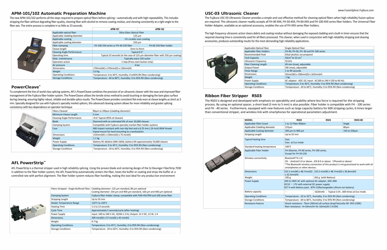
APM-101/102 Automatic Preparation Machine The new APM-101/102 performs all the steps required to prepare optical fibers before splicing – automatically and with high repeatability. This includes stripping the fiber without degrading fiber quality, cleaning fiber with alcohol to remove coating residue, and cleaving consistently at a right angle to the fiber axis. The entire process is complete in as little as 23 seconds.
APM-101 APM-102
Applicable optical fiber Silica Glass Optical Fiber
Applicable cladding diameter 125 µm
Applicable coating UV curable resin coating
Applicable coating diameter 250 µm
Fiber clamping FH-100-250 series or FH-40-250 fiber holder
FH-60-250 fiber holder
Cleave length 3mm to 9mm
Cleaving Angle Performance Typical 0.5°
Operating time Typical 23 seconds (in the case of 125 µm diameter fiber with 250 µm coating)
Daily maintenance Typically every 150 cycles
Operation action 1 step (Press start button only)
Air pressure 4 bar Dimensions 170mm(W) x 370mm(D) x 120mm(H)
Weight 5.0 kg
Operating Conditions Temperature: 0 to 40°C, Humidity: 0 to95% RH (Non-condensing) Storage Conditions Temperature: -40 to 80°C, Humidity: 0 to 95% RH (Non-condensing)
PowerCleave®
To complement the line of world class splicing systems, AFL’s PowerCleave combines the precision of an ultrasonic cleaver with the ease and improved fiber management of the Fujikura fiber holder system. The PowerCleave utilizes the tensile stress method to avoid touching or damaging the bare glass surface during cleaving, ensuring highly robust, reliable and durable splice results. The PowerCleave provides consistent flat ends even at cleave lengths as short as 3 mm. Specially designed for use with Fujikura’s specialty market splicers, this advanced cleaving system allows for more reliability and greater splicing consistency with less dependence on operator technique
Fibers Cleaved 80µm to 200µm (cladding diameter)
Minimum Cleave Length 3 mm
Cleaving Angle Performance <0.6 °typical (95% of cleaves)
Blade Diamond with an estimated life of over 20,000 cleaves
Clamping System Compatible with Fujikura specialty market fiber holder systems
Case ABS impact resistant with non-slip feet and a 6.25 mm (.24 inch) BSW thread tripod mount for hard mounting to a workstation
Dimensions 153mm(W) x 150mm(D) x 75 mm(H)
Weight 1.1 kg
Power Supply Battery 9V alkaline (MN 1604), battery life approximately 10,000 cleaves
Operating Conditions Temperature: 0 to 45°C, Humidity: 0 to 95% RH (Non-condensing)
Storage Conditions Temperature: -20 to 60°C, Humidity: 0 to 95% RH (Non-condensing)
AFL PowerStrip™
AFL PowerStrip is a thermal stripper used in high reliability splicing. Using the proven blade and centering design of the Sc hleuniger FiberStrip 7030 in addition to the fiber holder system, the AFL PowerStrip automatically centers the fiber, heats the buffer or coating and strips the buffer at a controlled rate with perfect alignment. The fiber holder system reduces fiber handling, making this tool ideal for any produc tion environment
USC-03 Ultrasonic Cleaner The Fujikura USC-03 Ultrasonic Cleaner provides a simple and cost effective method for cleaning optical fibers when high reliability fusion splices are required. This ultrasonic cleaner readily accepts all FH-40-XXX, FH-50-XXX, FH-60-XXX and FH-100-XXX series fiber holders. The Universal Fiber Holder Adapter, available as an optional accessory, enables the use of FH-XXX series fiber holders.
The high frequency ultrasonic action cleans debris and coating residue without damaging the exposed cladding and a built-in timer ensures that the required cleaning time is consistently used for all fibers processed. This cleaner, when used in conjunction with high reliability stripping and cleaving accessories, produces outstanding results for the most demanding high reliability applications.
Applicable Optical Fiber Single Optical Fiber
Applicable Fiber Holders FH-40, FH-50, FH- 60 and FH-100 series
Recommended Fluid Ethyl-alcohol, Iso-propanol
Tank Capacity 43cm3 to 53 cm3
Ultrasonic Frequency 50 kHz
Fiber Cleaning Length 49 mm (max), adjustable
Output Power 3W (max), adjustable
Timer Range 1 to 99 seconds
Dimensions 95mm(W) x 190mm(D) x 162mm(H) Weight 1 kg
Power Supply AC adapter: ADC-10, Input: AC100 to 240 V (50 to 60 Hz) Operating Conditions Temperature: 0 to 40°C, Humidity: 0 to 95% RH (Non-condensing)
Storage Conditions Temperature: -20 to 60°C, Humidity: 0 to 95% RH (Non-condensing)
Ribbon Fiber Stripper RS03 The RS03 is designed and developed with emphasis on operability and usability where less force is required for the stripping process. By using an optional spacer, a short lead (3 mm to 5 mm) is also possible. Fiber holder is compatible with FH - 100 series and FH - 40 series. Furthermore, equipped with new features such as large capacity battery for 600 stripping cycles, 6 times larger than conventional stripper, and wireless link with smartphones for operational parameters adjustment.
MODEL
RS02 RS03 RS03-80
Applicable Fiber Count 1 to 12 Fiber Ribbon Single
Applicable Cladding diameter 125µm 80µm
Applicable Coating diameter 200 µm to 400 µm 150 to 250µm
Stripping Length Up to 35 mm
Typical heating time 3sec 5sec at Eco mode
Standard heating temperature 100°C
Applicable Fiber Holder FH-50series, FH-60 series, FH-100 series, Except for FH-50-250
Wireless connectivity Bluetooth®4.1 LE
OS:Android 5.0 or above , iOS 8.0 or above(iPhone6 or above) *The Bluetooth wireless connection of this product is not guaranteed to work with all smartphones or other devices.
Dimensions 155.5 mm(W) x 48.7mm(D) x 32.5mm(H)
155.5 mm(W) x 48.7mm(D) x 36.8mm(H)
Weight 185 g 265 g (with Battery)
Power Supply 100 to 240V AC with optional AC adapter, ADC-09A
DC10 ~ 17V with external DC power supply: DC7.4 with Battery pack , BTR-12(Rechargeable Lithium-ion battery)
Battery capacity - 1620mAh : Typical 3.5h , 600 times at Eco mode
Operating Conditions Temperature: -10 to 50°C, Humidity: 0 to 95% RH (Non-condensing)
Storage Conditions Temperature: -40 to 80°C, Humidity: 0 to 95% RH (Non-condensing)
Resistance feature Shock resistance : 76cm (30inch) all surface drop(Telcordia GR -955-CORE) Rain resistance : H=10mm/hr for 10min(JIS C 0 034)
Fibers Stripped - Single Buffered Fiber Cladding diameter: 125 µm standard, 80 µm optional Coating diameter: 250 µm and 900 µm standard, 160 µm and 400 µm optional
Clamping System Fujikura fiber holder clamp; compatible with FSM-45F/PM and 100 series fiber holders Stripping Length Up to 35 mm
Heater Temperature Range 110°C to 150°C
Heating Time 1.5 to 13 seconds
Cycle Time Approximately 5 seconds/cycle (after heating)
Power Supply Input: 100 to 240 V AC, 50/60 ± 3 Hz; Output: 12 V DC, 12 W, 1 A
Dimensions 209 mm(W) x 57 mm(D) x 45 mm(H)
Weight 0.7 kg
Operating Conditions Temperature: 0 to 45°C, Humidity: 0 to 95% RH (Non-condensing)
Storage Conditions Temperature: -20 to 60°C, Humidity: 0 to 95% RH (Non-condensing)

www.FusionSplicer.Fujikura.com
AutoCleaver LDF
The AutoCleaver LDF is a high precision fiber cleaver, designed for cleaving of Large Diameter Fibers. It provides outstanding cleaving performance for large diameter fibers from 250 μm up to 1200 μm in diameter. It also supports cleaving of fibers as small as 125 μm. The unique and patent-pending cleaving process generates typical cleave angles of less than 0.5 degrees with LDF fibers.
The AutoCleaver LDF can be configured for use with the Fujikura FSM-45 and FSM-100 series of fusion splicers and therefore supports splicing
operations with large diameter fibers. The cleaved fiber is transferred from the cleaver to the Fujikura splicer using a standard Fujikura fiber holder.
The built in Microprocessor controls all vital parameters and settings, such as fiber alignment, clamping, tension and the exact position and speed of
the diamond blade. This control of sensitive parameters guarantees a high cleaving repeatability and accuracy.
PCS-100 Polyimide Coating Stripper Polyimide coated optical fiber are now widely used in the oil and gas and medical industries. The polyimide coating has sup erior heat and chemical resistance to conventional UV curable coating material, but the coating requires additional care to remove. Dangerous chemica l stripping using hot sulfuric acid or burning the coating off are common methods to strip the fiber due to the thin coating and strong coating adhesion to the fiber cladding. The PCS-100 Polyimide Fiber Coating Stripper is the first tool that uses a mechanical stripping method, providing a safe, consistent and quick stripping solution.
* Fiber specific handling kits required
** Not included in delivery
CleaveMeter 2™
The CleaveMeter 2 is a non-contact interferometer designed for inspecting the end-faces of cleaved and polished optical fibers with cladding diameters of 125 μm to 1200 μm. It gives immediate information on important end-face properties such as flatness, perpendicularity, hackles and dust. Sampling tests as well as continuous process documentation can be carried out both easily and quickly, making this an ideal instrument for cleaver inspection and optimization.
The optical system is based on a high-end camera with true megapixel resolution and very high sensitivity, yielding excellent image quality at high frame rates and high magnification. Switching between low and high magnification is software-controlled. High-precision optics guarantees sharp and clear images and fringe patterns with very little aberration.
Applicable optical fiber Glass optical fibers, capillary
Number of fibers Single
Fiber Cladding 125μm to 1200μm*
Fiber Coating 250μm to 1500μm
Camera Resolution: 1280 × 1024 pixels
Image Scale: 1.25μm per pixel
Image file format 8-bit JPEG, PNG, TIFF, BMP
Absolute Accuracy 0.15/0.03 degrees**
Relative Accuracy 20 % (125μm to 199µm); 10 % (200μm to 529µm); 5 % (530μm to 1200µm)
Image File Format: 8-bit JPEG, PNG, TIFF, BMP
PC Connection: USB 2.0 port
Dimensions 97 mm(W) × 179 mm(D) × 142 mm(H)
Weight 1.6kg
Power Supply: Through USB port
Operating Conditions Temperature: 0 to 40°C, Humidity: 0 to 95% RH (Non-condensing)
Storage Conditions Temperature: -40 to 80°C, Humidity: 0 to 95% RH (Non-condensing)
* Fiber specific adapter plates required ** This level of accuracy requires adapter plate angle errors to be measured/compensated on the individual CleaveMeters they are used with (Premium software only).
FSR-05, FSR-06 and FSR-07 Fiber Recoaters The FSR-05, FSR-06 and FSR-07 provide automatic operation with various sizes of quartz molds available (195 μm, 255 μm, 280 μm, 450 μm,
670 μm, 1000 μm). Colored and non-colored fibers can be recoated. This new recoater family introduces easily exchangeable molds, resin bottle and pump assembly. The new bubble removal system eliminates bubbles before they reach the mold cavity. A programmable resin injection system provides an exact volume of resin to the mold cavity to ensure consistent recoat performance. The FSR-06 and FSR-07 also provide programmable rate and force for proof testing capabilities up to 2 kgf or 10 kgf respectively. All of the recoaters are compatible with special recoating resins to provide higher stiffness recoating of 900 μm jacketed fibers, as well as specialty low-index resins for recoating of double-clad fibers. A USB - PC interface allows the user to control and store key parameters associated with the recoating process. The quartz mold technology provides very consistent mold quality after thousands of uses with an estimated lifetime of 10,000 recoats per mold set. Patent Pending.
PARAMETER FSR-05 FSR-06 FSR-07
Applicable Optical Fiber coating
Colored and non-colored
Recoating diameter 195μm, 255μm, 280μm,320μm, 450μm, 600μm,670μm, 1000μm - Custom sizes are available
Recoating length 4mm to 50 mm
Recoating time Injection 20 seconds/Curing 4 seconds (Jacket diameter 250μm with 280μm MOLD)
Resin injection Volume and speed are programmable
Recoat material UV curable Acrylate. Recommended specification for other viscosity 2000-6000 cps Curing wavelength 365± 15 nm. DSM Desotech DesoLite(R) 950-200 recommended
Material of mold Quartz
Recoat modes 100 modes - All variables programmable
Proof-test modes NA 30 modes - speed, force, time programmable
Load application NA Linear Clamp Mandrel
Tension NA 0.5kgf to 2.0kgf 0.5kgf to 10.0kgf
LCD monitor 4.7 inch, color LCD, Tilt angle
PC interface USB 2.0 Type B mini
Dimensions 252 mm(W) x 135 mm (D) x 169mm(H)
252 mm (W) x 175 mm (D) x 169 mm (H)
Weight 2.9kg 4.3kg 4.5kg
Power Supply AC adapter: ADC-19, Input: AC100 to 240 V (50 to 60 Hz) (max. 20 W)
Operating condition Temperature: 10 to30°C, Humidity: 0 to 95% RH (Non-condensing)
Storage condition Temperature: -40 to 60°C, Humidity: 0 to 95% RH (Non-condensing), no resin
Applicable Optical Fiber Silica based Single-mode and Multimode glass fiber
Applicable Coating Polyimide coating and UV curable resin coating
Cladding Diameter Range 60 to 1200 μm
Coating Diameter Range 60 to 1,500 μm
Fiber Clamping Adaptable to range of fiber/coating sizes by selection of applicable pair of FH-100-XXX series fiber holders
Strip Length 1 to 35 mm
Stripping Time 4 stripping passes: 20 seconds 8 stripping passes: 35 seconds 12 stripping passes: 50 seconds
CE Conformity Complies with all CE equipment guidelines
Blade Life 350 fibers / blade (In the case of 4 strips per fiber)
Stripping Modes 30 user-programmable modes
Proof Modes 30 user-programmable modes
Maximum Proof Test Force
2 kgf
Typical Proof Test Cycle Time
3 seconds
Dimensions 230 mm (W) x 214 mm (D) x 151 mm (H)
Weight 5.0 kg excluding AC adapter
Power Input AC100 to 240 V (50 Hz to 60 Hz)
Operating Conditions Temperature: 0 to 40°C, Humidity: 0 to 95% RH (Non-condensing)
Storage Conditions Temperature: -40 to 80°C, Humidity: 0 to 95% RH (Non-condensing)
Cycle Time Typical < 14 seconds
Cleave Angle Typical < 0.5º
Cladding Diameter 230µm to 1000µm
Coating Diameter 250µm to 1500µm
Fiber Waste Typical < 20 mm
PC Connection RS-232
Dimensions 175 mm(W) x 138 mm(D) x 104 mm(H)
Weight 2.5 kg
Power Supply External 12V DC
Compressed Air External Compressor**, 6 bar 4 mm instant push-in fitting
Operating Conditions Temperature: 0 to 40°C, Humidity: 0 to 95% RH (Non-condensing)
Storage Conditions Temperature: -40 to 80°C, Humidity: 0 to 95% RH (Non-condensing)
FSR-05
FSR-07
FSR-06

www.FusionSplicer.Fujikura.com
CT-32 Fiber Cleaver The CT-32 is a modified version of our standard cleaver model CT-30. The modifications allow use of a spacer system that provides for the full range of acceptable cleave lengths for use with our FSM-45 and FSM-100 series factory fusion splicers. The CT-32 also allows for a reduced cleave length of 8 mm on 900 µm jacketed fibers and as short as 3 mm on 250 µm and 400 µm coated fibers. Included with the CT-32 is a 1 mm spacer that allows for the recommended cleave lengths for use with our factory fusion splicer models.
Applicable optical fiber Silica Glass Optical Fiber
Number of fibers Single
Cladding diameter 125 µm
Coating diameter 0.25 mm to 0.9 mm depending on fiber holder (FH-40 or FH-100 series)
Cleaving Angle Performance Typically <0.5˚
Blade lifetime 48,000 cleaves (1,000 x 3 heights x 16 positions )
Dimensions 105 mm(W) x 82 mm(D) x 46 mm(H)
Weight 180 g
Operating Conditions Temperature: 0 to 40°C, Humidity: 0 to 95% RH (Non-condensing)
Storage Conditions Temperature: -40 to 80°C, Humidity: 0 to 95% RH (Non-condensing)
CT-38 Fiber Cleaver The CT-38 cleaver is designed for cleaving silica fibers with 80 µm cladding. Utilizing the same one step design of our popular CT-30 cleaver, the CT-38 is quick, easy, and dependable. The 16 position blade yields 48,000 cleaves by providing for blade height and position adjustments. The cleaver can be used with either the FSM-45 or FSM-100 series fiber holder systems or with the optional AD-30A adapter plate for other applications.
Applicable optical fiber Silica Glass Optical Fiber
Number of fibers Single
Cladding diameter 80µm
Coating diameter 0.10mm to 0.25mm depending on fiber holder (FH-40 or FH-100 series)
Cleaving Angle Performance Typically <0.5˚
Blade lifetime 48,000 cleaves (1,000 x 3 heights x 16 positions )
Dimensions 66 mm(W) x 82mm(D) x 46mm(H)
Weight 180g
Operating Conditions Temperature: 0 to 40°C, Humidity: 0 to 95% RH (Non-condensing)
Storage Conditions Temperature: -40 to 80°C, Humidity: 0 to 95% RH (Non-condensing)
CT-101 and CT-102 Fiber Cleaver Precise cleaving is required for photonic splicing applications as the types of optical fiber become more diversified to meet new applications. In addition, angled cleaving is often required for low back-reflection fiber end preparation. The CT-101 and CT-102 have been developed to offer
adjustability and versatility for these various fiber types and applications while offering superior tension cleaving perform ance beyond
conventional cleavers that utilize a scribe and bend cleaving method. The CT-101 and CT-102 are equipped with a motorized diamond blade that
touches the fiber after tension has been applied providing high-strength cleaving capability. The CT-101 is designed to accommodate the Fujikura
FH-100 fiber holders while the CT-102 has been designed to accommodate the FH-60 fiber holders.
CT-101/CT-102
PARAMETER CT-101 CT-102
Applicable optical Fiber Silica Glass Optical Fiber
Number of fibers Single
Cladding Diameter 80µm to 250µm
Coating Diameter 160µm to 2000 µm
Cleave Angle Capability 0 ˚ to 15 ˚ (adjustable)
Cleave Length 0mm to 40mm
Fiber Holder FH-100 series FH-60 series
Cleaving Angle Performance Typical 0.3˚ (SMF28e)
Blade Life time 20,000 fibers (1,000 fibers x 20 positions)
Dimensions 140 mm (W) x 110 mm (D) x 95 mm (H)
Weight 900 g or less (excluding batteries)
Power Supply a) 4 “AA” size batteries (approx. 2000 cleaves) b) AC adapter: ADC-16, Input: AC100 to 240 V (50 to 60 Hz)
Operating Conditions Temperature: 0°C to 40°C, Humidity: 0% to 95% RH (Non-condensing)
Storage Conditions Temperature: -40°C to 80°C, Humidity: 0% to 95% RH (Non-condensing)
CT-104, CT-105 and CT-106 Fiber Cleavers
When exceptional cleave quality is required for fibers up to 1,250 μm, the new large diameter CT-104/CT-105/CT-106 cleaver family provides a variety
of options depending on your needs. The color LCD shows cleaving progress and recommended insert size depending on fiber coating and cladding
diameter. Saving and storing cleaving programs to a PC or tablet is accomplished using a USB port. The LDF cleaver’s extensive programming features
allow for optimal results.
PARAMETER CT-104 CT-105 CT-106
Applicable optical fiber Glass optical fibers, capillary
Number of fibers Single
Cladding diameter 80μm to 600μm 80μm to 1,250μm
Coating diameter 160μm to 3,000μm
Fiber clamping Manual clamping with torque driver when required
Automatic clamping
Cleaving length 5mm to 40 mm
Angled cleaving NA NA 0 °to 15° (up to 800μm cladding fiber)
Blade life time 20,000 fibers (Cladding diameter 125μm)
Number of cleaving mode Maximum 100
Language English/Japanese
Monitor 4.7 inch, color LCD, Tilt angle
Terminal USB 2.0 (Mini-B type) for PC communication
Dimensions 240 mm(W)× 134 mm(D) × 155mm(H) 240 mm(W) × 134mm(D) × 62.5mm (H) mm Weight 3.4 kg 3.5 kg 3.8 kg
Power supply AC adapter: ADC-19, Input: AC100 to 240 V (50 to 60 Hz) (max. 20 W)
Operating condition Temperature: 0°C, to 40°C, Humidity: 0% to 95% RH (Non-condensing)
Storage condition Temperature: -40°C, to 80°C, Humidity: 0% to 95% RH (Non-condensing)
Splice Protection Sleeves Fujikura offers a wide selection of fiber protection sleeves to meet any application. The FP -03 series is the industry standard for durable and lasting protection of single fiber splices in field installations, while the FP-04(T) and FP-05 provide the same durable protection for 8 and 12 fiber ribbon respectively.
The FPS series are specially designed for optical components, where small packaging is a priority. These micro sleeves provide the known reliability of Fujikura sleeves in the smallest possible lengths. This easy and cost effective method is a great alternative to recoating. The FPS series offer a wide range of options to accommodate various coating sizes, and are manufactured in a variety of lengths. This gives great flexibility in designing optical modules.
Outer tube FP-03 series / FPS series FP-04(T) / FP-05 Polyethylene
Inner tube FP-03 series / FPS series FP-04(T) / FP-05 Ethylene-Vinyl Acetate (Polyolefin Copolymer)
Strength member FP-03 series / FPS series FP-04 (T) Stainless steel
FP-05 Quartz glass
Operating condition (after shrink) Temperature: -40°C to 75°C, Humidity: 0% to 95% RH (Non-condensing)
Storage condition (before shrink) Temperature: -40°C to 60°C, Humidity: 0% to 95% RH (Non-condensing)
CT-104
CT-105
CT-106


Ⓒ 2016 Fujikura Ltd
Fujikura Ltd. Fujikura Asia Ltd.
Fujikura Europe Ltd.
AFL
Specifications and descriptions are subject to change without prior notice.
1-5-1, Kiba, Koto-ku, Tokyo 135-8512, Japan Phone : +81-3-5606-1164 Fax : +81-3-5606-1534 http://www.fujikura.co.jp
460, Alexandra Road, #22-02 PSA Bldg., Singapore 119963 Phone : +65-6-271-1312 Fax : +65-6-278-0965 http://www.fujikura.co.sg
C51 Barwell Buisiness Park, Leatherhead Road, Chessington, Surrey KT9 2NY, UK Phone : +44-20+8240-2000 Fax : +44-20-8240-2010 http://www.fujikura.co.uk
260, Parkway East, Hillside Industrial Park, Duncan, SC 29334 USA Phone : +1-800-235-3423 Fax : +1-800-926-0007 http://www.AFLglobal.com
7th Floor, HSBC Tower,1000 Lujiazui Ring Road, Pudong, Shanghai 200120, China. Phone : +86-21-6841-3636 Fax : +86-21-6841-2070 http://www.fujikura.com.cn
BRO-0404_SpecialitySplicing_brochure 12_21_16 .
Fujikura (China) Co., Ltd