qlogic fibre channel switch module for ibm
TRANSCRIPT
QLogic Fibre Channel Switch Module for IBM
Eserver BladeCenter
Installation Guide
���


QLogic Fibre Channel Switch Module for IBM
Eserver BladeCenter
Installation Guide
���
Note:
Before using this information and the product it supports, read the general information
in Appendix B, “Warranty information,” on page 61 and “Notices” on page 85.
First Edition (September 2005)
© Copyright International Business Machines Corporation 2005. All rights reserved.
US Government Users Restricted Rights – Use, duplication or disclosure restricted by
GSA ADP Schedule Contract with IBM Corp.
Contents
Safety . . . . . . . . . . . . . . . . . . . . . . . . v
Chapter 1. Introduction . . . . . . . . . . . . . . . . . . 1
Related documentation . . . . . . . . . . . . . . . . . . . 3
The Support CD . . . . . . . . . . . . . . . . . . . . . 6
Notices and statements used in this document . . . . . . . . . . . 6
Features and specifications . . . . . . . . . . . . . . . . . . 7
Inventory checklist . . . . . . . . . . . . . . . . . . . . 10
Major components of the I/O module . . . . . . . . . . . . . 11
Chapter 2. Installing and removing an I/O module . . . . . . . . 13
Installation guidelines . . . . . . . . . . . . . . . . . . . 14
System reliability considerations . . . . . . . . . . . . . . 15
Handling static-sensitive devices . . . . . . . . . . . . . . 15
Installing a BladeCenter Fibre Channel switch module . . . . . . . . 17
Removing a BladeCenter Fibre Channel switch module . . . . . . . . 21
Chapter 3. Information panel LEDs and external ports . . . . . . . 25
Information panel . . . . . . . . . . . . . . . . . . . . 25
Information LEDs . . . . . . . . . . . . . . . . . . . . 26
Chapter 4. Configuring the switch module through the Telnet interface 29
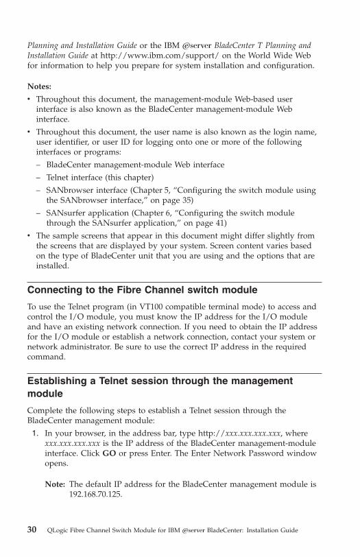
Connecting to the Fibre Channel switch module . . . . . . . . . . 30
Establishing a Telnet session through the management module . . . . . 30
Establishing a Telnet session in a command-line window . . . . . . . 32
CLI command format . . . . . . . . . . . . . . . . . . . 34
Chapter 5. Configuring the switch module using the SANbrowser
interface . . . . . . . . . . . . . . . . . . . . . . 35
Connecting to the switch module . . . . . . . . . . . . . . . 36
Establishing a Web-interface session through the management module . . 36
Establishing a Web-interface session through a Web browser . . . . . . 38
Chapter 6. Configuring the switch module through the SANsurfer
application . . . . . . . . . . . . . . . . . . . . . 41
System requirements . . . . . . . . . . . . . . . . . . . 42
Installing the SANsurfer application on a Microsoft Windows 2000 or
Microsoft Windows 2003 platform . . . . . . . . . . . . . . 43
Uninstalling the SANsurfer application on a Microsoft Windows 2000 or
Microsoft Windows 2003 platform . . . . . . . . . . . . . . 44
Installing the SANsurfer application on Red Hat Linux or SUSE LINUX
platform . . . . . . . . . . . . . . . . . . . . . . 45
© Copyright IBM Corp. 2005 iii

Uninstalling the SANsurfer application from a Linux operating system . . 46
Using the SANsurfer application . . . . . . . . . . . . . . . 47
Starting the SANsurfer application and adding a new fabric . . . . . 47
Changing the encryption key for the default fabric view . . . . . . 48
Setting user preferences . . . . . . . . . . . . . . . . . 48
Using online help . . . . . . . . . . . . . . . . . . . 49
Exiting the SANsurfer application . . . . . . . . . . . . . . 49
SANsurfer Topology and Faceplate windows . . . . . . . . . . . 50
Chapter 7. Expanding the functionality of the switch module . . . . 55
Purchasing the optional software feature . . . . . . . . . . . . 55
Installing the optional software feature . . . . . . . . . . . . . 56
Appendix A. Getting help and technical assistance . . . . . . . . 57
Before you call . . . . . . . . . . . . . . . . . . . . . 57
Using the documentation . . . . . . . . . . . . . . . . . . 58
Getting help and information from the World Wide Web . . . . . . . 58
Software service and support . . . . . . . . . . . . . . . . 58
Hardware service and support . . . . . . . . . . . . . . . . 59
Appendix B. Warranty information . . . . . . . . . . . . . . 61
IBM Statement of Limited Warranty Z125-4753-08 04/2004 . . . . . . 61
Part 1 - General Terms . . . . . . . . . . . . . . . . . . 61
Part 2 - Country-unique Terms . . . . . . . . . . . . . . . 66
Part 3 - Warranty Information . . . . . . . . . . . . . . . 81
Notices . . . . . . . . . . . . . . . . . . . . . . . 85
Edition notice . . . . . . . . . . . . . . . . . . . . . 86
Trademarks . . . . . . . . . . . . . . . . . . . . . . 86
Important notes . . . . . . . . . . . . . . . . . . . . . 87
Product recycling and disposal . . . . . . . . . . . . . . . . 88
Electronic emission notices . . . . . . . . . . . . . . . . . 88
Federal Communications Commission (FCC) statement . . . . . . . 88
Industry Canada Class A emission compliance statement . . . . . . 90
Australia and New Zealand Class A statement . . . . . . . . . 90
United Kingdom telecommunications safety requirement . . . . . . 90
European Union EMC Directive conformance statement . . . . . . 90
Taiwanese Class A warning statement . . . . . . . . . . . . 91
Chinese Class A warning statement . . . . . . . . . . . . . 91
Japanese Voluntary Control Council for Interference (VCCI) statement 91
Index . . . . . . . . . . . . . . . . . . . . . . . . 93
iv QLogic Fibre Channel Switch Module for IBM Eserver BladeCenter: Installation Guide

Safety
Before installing this product, read the Safety Information.
Antes de instalar este produto, leia as Informações de Segurança.
Pred instalací tohoto produktu si prectete prírucku bezpecnostních instrukcí.
Læs sikkerhedsforskrifterne, før du installerer dette produkt.
Lees voordat u dit product installeert eerst de veiligheidsvoorschriften.
Ennen kuin asennat tämän tuotteen, lue turvaohjeet kohdasta Safety
Information.
Avant d’installer ce produit, lisez les consignes de sécurité.
Vor der Installation dieses Produkts die Sicherheitshinweise lesen.
Prima di installare questo prodotto, leggere le Informazioni sulla Sicurezza.
© Copyright IBM Corp. 2005 v

Les sikkerhetsinformasjonen (Safety Information) før du installerer dette
produktet.
Antes de instalar este produto, leia as Informações sobre Segurança.
Antes de instalar este producto, lea la información de seguridad.
Läs säkerhetsinformationen innan du installerar den här produkten.
Important:
All caution and danger statements in this documentation begin
with a number. This number is used to cross reference an English
caution or danger statement with translated versions of the caution
or danger statement in the IBM Safety Information book.
For example, if a caution statement begins with a number 1,
translations for that caution statement appear in the IBM Safety
Information book under statement 1.
Be sure to read all caution and danger statements in this
documentation before performing the instructions. Read any
additional safety information that comes with the blade server or
optional device before you install the device.
vi QLogic Fibre Channel Switch Module for IBM Eserver BladeCenter: Installation Guide

Statement 1:
DANGER
Electrical current from power, telephone, and communication cables is
hazardous.
To avoid a shock hazard:
v Do not connect or disconnect any cables or perform installation,
maintenance, or reconfiguration of this product during an electrical
storm.
v Connect all power cords to a properly wired and grounded electrical
outlet.
v Connect to properly wired outlets any equipment that will be attached
to this product.
v When possible, use one hand only to connect or disconnect signal
cables.
v Never turn on any equipment when there is evidence of fire, water, or
structural damage.
v Disconnect the attached power cords, telecommunications systems,
networks, and modems before you open the device covers, unless
instructed otherwise in the installation and configuration procedures.
v Connect and disconnect cables as described in the following table
when installing, moving, or opening covers on this product or attached
devices.
To Connect: To Disconnect:
1. Turn everything OFF.
2. First, attach all cables to devices.
3. Attach signal cables to connectors.
4. Attach power cords to outlet.
5. Turn device ON.
1. Turn everything OFF.
2. First, remove power cords from outlet.
3. Remove signal cables from connectors.
4. Remove all cables from devices.
Safety vii
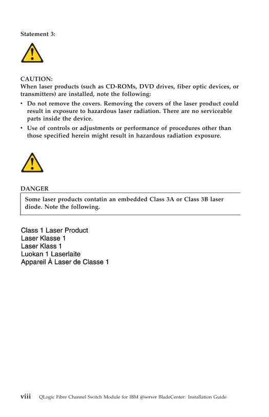
Statement 3:
CAUTION:
When laser products (such as CD-ROMs, DVD drives, fiber optic devices, or
transmitters) are installed, note the following:
v Do not remove the covers. Removing the covers of the laser product could
result in exposure to hazardous laser radiation. There are no serviceable
parts inside the device.
v Use of controls or adjustments or performance of procedures other than
those specified herein might result in hazardous radiation exposure.
DANGER
Some laser products contatin an embedded Class 3A or Class 3B laser
diode. Note the following.
Class 1 Laser ProductLaser Klasse 1Laser Klass 1Luokan 1 LaserlaiteAppareil A Laser de Classe 1`
viii QLogic Fibre Channel Switch Module for IBM Eserver BladeCenter: Installation Guide

Statement 5:
CAUTION:
The power control button on the device and the power switch on the power
supply do not turn off the electrical current supplied to the device. The
device also might have more than one power cord. To remove all electrical
current from the device, ensure that all power cords are disconnected from
the power source.
1
2
Statement 8:
CAUTION:
Never remove the cover on a power supply or any part that has the
following label attached.
Hazardous voltage, current, and energy levels are present inside any
component that has this label attached. There are no serviceable parts inside
these components. If you suspect a problem with one of these parts, contact
a service technician.
WARNING: Handling the cord on this product or cords associated with
accessories sold with this product, will expose you to lead, a chemical known
to the State of California to cause cancer, and birth defects or other
reproductive harm. Wash hands after handling.
Safety ix

ADVERTENCIA: El contacto con el cable de este producto o con cables de
accesorios que se venden junto con este producto, pueden exponerle al plomo,
un elemento químico que en el estado de California de los Estados Unidos está
considerado como un causante de cancer y de defectos congénitos, además de
otros riesgos reproductivos. Lávese las manos después de usar el producto.
x QLogic Fibre Channel Switch Module for IBM Eserver BladeCenter: Installation Guide

Chapter 1. Introduction
This Installation Guide contains instructions for and information about:
v Installing and setting up the QLogic® Fibre Channel Switch Module for
IBM®
Eserver
® BladeCenter®
v Configuring the switch module through the Telnet interface
v Configuring the switch module through the SANbrowser interface
v Configuring the switch module through the SANsurfer application
v Expanding the functionality of the switch module (optional)
For installation details, see Chapter 2, “Installing and removing an I/O
module,” on page 13. For details about the status of the switch module and its
external ports and network connections, see Chapter 5, “Configuring the switch
module using the SANbrowser interface,” on page 35. For additional
information about switch modules and other BladeCenter components, see the
instructions in your BladeCenter documentation.
Notes:
v Except where specifically stated otherwise in this document, the terms I/O
module, switch module, or switch refer to the QLogic 20-port 4 Gb Fibre
Channel switch module, the QLogic 10-port 4 Gb Fibre Channel switch
module, and the QLogic 6-port Enterprise Fibre Channel switch module
(2Gb).
v Except where specifically stated otherwise in this document, the IBM
Eserver BladeCenter unit (for example, the BladeCenter Type 8677) and IBM
Eserver BladeCenter T unit are referred to as the BladeCenter unit.
v When using the 4 Gb switch module with the BladeCenter T unit, the
internal ports operate at 2 Gigabits per second (Gbps). The external ports
operate at 4 Gbps.
v You can install up to two I/O modules in a BladeCenter unit.
You can manage and configure the I/O module through multiple interfaces:
v A Telnet connection to the embedded command-line interface (CLI)
For additional information, see Chapter 4, “Configuring the switch module
through the Telnet interface,” on page 29.
v A Web browser (SANbrowser) interface
For additional information, see Chapter 5, “Configuring the switch module
using the SANbrowser interface,” on page 35.
© Copyright IBM Corp. 2005 1
v The SANsurfer application
The SANsurfer application provides an intuitive graphical interface that you
can use to configure multiple I/O modules through other connected storage
area network (SAN) devices from a single interface. For additional
information, see Chapter 6, “Configuring the switch module through the
SANsurfer application,” on page 41.
You can obtain up-to-date information about the I/O module and other IBM
Eserver products at http://www.ibm.com/eserver/.
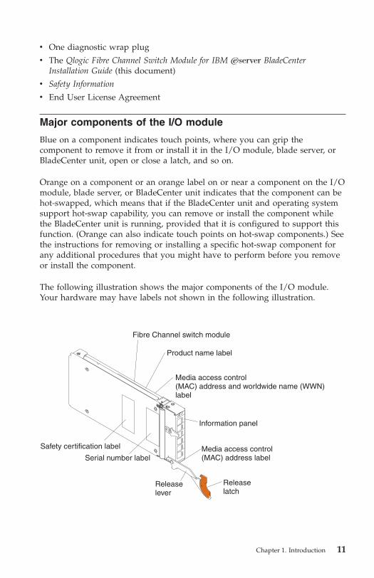
This I/O module has six labels: a safety certification label, a Common
Language Equipment Identification (CLEI) label, a product name label, a serial
number label, a media access control (MAC) address label, and a media access
control address/worldwide name (MAC address/WWN) label. The safety
certification label is on the left side of the I/O module. The product name label
is on the right side of the I/O module. The CLEI label is on the left side of the
I/O module. The serial number label is on the left side of the I/O module. The
MAC address label is on the information panel under the I/O-module external
port 19. The MAC address/WWN label is on the right side of the I/O module.
You will need this information when you register the I/O module with IBM.
See “Major components of the I/O module” on page 11 for the location of the
I/O-module labels that contain the MAC address/WWN and serial number
information.
You can expand the functionality of the I/O module through the purchase of
an optional software license that provides additional capabilities. For
additional information, see Chapter 7, “Expanding the functionality of the
switch module,” on page 55.
Before you can expand the functionality of the I/O module and install a new
software license, you must determine the product serial number of the switch
module. Use the Telnet program to log in to the switch module as described in
Chapter 5, “Configuring the switch module using the SANbrowser interface,”
on page 35, and run the show version command to determine the value of the
Chassis Serial Number data field. Record the serial number for future
reference; for example, 11S32R1793ZJ1ZC846H073. For information about the
show version command, see the QLogic Fibre Channel Switch Module for IBM
Eserver BladeCenter Management Guide at http://www.ibm.com/support/ or
on the Support CD.
2 QLogic Fibre Channel Switch Module for IBM Eserver BladeCenter: Installation Guide

Record your product information in this table
Product name: ____ QLogic 20-port 4 Gb Fibre Channel Switch Module
for IBM Eserver BladeCenter
or
Product name: ____ QLogic 10-port 4 Gb Fibre Channel Switch Module
for IBM Eserver BladeCenter
or
Product name: ____ QLogic 6-port Enterprise Fibre Channel Switch Module
for IBM Eserver BladeCenter
Chassis serial number: __________________________________________________
For example: 11S32R1793ZJ1ZC846H073
Media access control (MAC) address: ______________________________________
Worldwide name (WWN): ______________________________________
Related documentation
This Installation Guide contains installation and setup instructions for the I/O
module. This document also provides general information about the I/O
module, including getting started, how to configure the I/O module, and how
to access and use online help.
This Installation Guide is also provided in Portable Document Format (PDF) on
the QLogic 4Gb Fibre Channel Switch Module for IBM Eserver BladeCenter Support
CD that comes with the switch module. Throughout this document, this CD is
also referred to as the Support CD. For additional information about the Support
CD, see “The Support CD” on page 6.
In addition to reviewing the documentation in this library, be sure to review
the IBM Eserver BladeCenter Planning and Installation Guide or the IBM Eserver
BladeCenter T Planning and Installation Guide for information to help you
prepare for system installation and configuration.
The most recent version of the following related BladeCenter documentation is
available in PDF on the World Wide Web.
To locate the most recent version of the BladeCenter documentation, including
the IBM Eserver BladeCenter Planning and Installation Guide or the IBM Eserver
BladeCenter T Planning and Installation Guide, complete the following steps:
1. Go to http://www.ibm.com/support/.
2. In the Browse by topic section, click Publications.
Chapter 1. Introduction 3

3. On the “Publications” page, in the Brand field, select Servers.
4. In the Family field, select BladeCenter.
Do not change the default values in the Type, Model, or Operating system
fields.
5. Click Continue.
A list of the available BladeCenter documentation will be displayed under
the heading Results by date.
Notes:
v To display different results, you can select BladeCenter HS20, BladeCenter
HS40, BladeCenter LS20, or BladeCenter JS20.
v Changes are made periodically to the IBM Web site. The actual procedure
might vary from what is described in this document.
In addition to this Installation Guide, the following related documentation is
available in PDF on the World Wide Web or on the Support CD that comes
with the switch module:
v QLogic Fibre Channel Switch Module for IBM Eserver BladeCenter Management
Guide
This document describes how to use the SANsurfer application. In addition,
it describes how to start the Telnet CLI and lists the CLI commands and
their usage. This document also contains diagnostic information that pertains
to the switch module.
v QLogic 6-port Fibre Channel Switch Module for IBM Eserver BladeCenter
Management Guide
This document describes how to use the SANsurfer application. In addition,
it describes how to start the Telnet CLI and lists the CLI commands and
their usage. This document also contains diagnostic information that pertains
to the switch module.
v Safety Information
This document contains translated caution and danger statements. Each
caution and danger statement that appears in the documentation has a
number that you can use to locate the corresponding statement in your
language in the Safety Information document.
v IBM Eserver BladeCenter Fibre Channel Expansion Card Installation and User’s
Guide
This document contains instructions for installing the IBM BladeCenter™
Fibre Channel expansion card in an IBM blade server. This document
contains information about:
– Installing and configuring the Fibre Channel expansion card
– Updating the basic input/output system (BIOS) code and device drivers
of the Fibre Channel expansion card
4 QLogic Fibre Channel Switch Module for IBM Eserver BladeCenter: Installation Guide
v QLogic Fibre Channel Expansion Card for IBM Eserver BladeCenter Installation
and User’s Guide
This document contains instructions for installing the QLogic Fibre Channel
expansion card in an IBM blade server. This document contains information
about:
– Installing and configuring the Fibre Channel expansion card
– Updating the basic input/output system (BIOS) code and device drivers
of the Fibre Channel expansion card
v IBM Eserver BladeCenter and BladeCenter T unit Installation and User’s
Guide
Each type of BladeCenter unit has a customized Installation and User’s Guide.
It provides general information about your BladeCenter unit, including:
– Information about features
– How to set up, cable, and start your BladeCenter unit
– How to install options in your BladeCenter unit
– How to configure your BladeCenter unit
– How to perform basic troubleshooting of your BladeCenter unit
– How to get help
v IBM Eserver BladeCenter blade server Installation and User’s Guide
Each type of blade server has a customized Installation and User’s Guide. It
provides general information about your blade server, including:
– Information about features
– How to set up and start your blade server
– How to install options in your blade server
– How to configure your blade server
– How to install an operating system on your blade server
– How to perform basic troubleshooting of your blade server
– How to get help
v Rack Installation Instructions
This document contains the instructions to install your BladeCenter unit in a
rack.
v IBM Problem Determination and Service Guide or Hardware Maintenance Manual
and Troubleshooting Guide
All types of BladeCenter units and blade servers come with a customized
Problem Determination and Service Guide or Hardware Maintenance Manual and
Troubleshooting Guide. Some BladeCenter options might also come with a
customized Problem Determination and Service Guide or Hardware Maintenance
Manual and Troubleshooting Guide. This document contains information to
help you solve the problem yourself or to provide helpful information to a
service technician.
Chapter 1. Introduction 5
The IBM Configuration and Options Guide contains information about which
small-form-factor pluggable (SFP) module and cable are required to connect
the I/O module to other storage devices. This document is at
http://www.ibm.com/servers/eserver/xseries/library/configtools.html on the
World Wide Web.
Additional related documentation might be included on the Support CD or
available on the IBM support Web site, http://www.ibm.com/support/.
The Support CD
The Support CD contains the following items:
v SANsurfer application software
v The \Publications folder, which includes PDF files for the following
documentation:
– QLogic Fibre Channel Switch Module for IBM Eserver BladeCenter
Management Guide
– QLogic Fibre Channel Switch Module for IBM Eserver BladeCenter Event
Message Guide
v Readme files
v Instructions
Note: The Support CD might contain additional information. Use the
subdirectories to help you find information quickly.
Notices and statements used in this document
The caution and danger statements used in this document are also in the
multilingual Safety Information document, which is on the Support CD. Each
statement is numbered for reference to the corresponding statement in the
Safety Information document.
The following notices and statements are used in this document:
v Note: These notices provide important tips, guidance, or advice.
v Important: These notices provide information or advice that might help you
avoid inconvenient or problem situations.
v Attention: These notices indicate potential damage to programs, devices, or
data. An attention notice is placed just before the instruction or situation in
which damage could occur.
v Caution: These statements indicate situations that can be potentially
hazardous to you. A caution statement is placed just before the description
of a potentially hazardous procedure step or situation.
6 QLogic Fibre Channel Switch Module for IBM Eserver BladeCenter: Installation Guide
v Danger: These statements indicate situations that can be potentially lethal or
extremely hazardous to you. A danger statement is placed just before the
description of a potentially lethal or extremely hazardous procedure step or
situation.
Features and specifications
This section provides a summary of the features and specifications for the I/O
module.
The I/O module has the following features:
v Simple name server implementation
The simple name server is implemented as described in Fibre Channel
Generic Services (FC-GS-3). The simple name server requests and responses
are based on the Common Transport Interface (CTI) as described in FC-GS-3.
Name server database objects are defined as follows:
– Native Port Identifier (P_ID)
– Port Name (PN)
– Node Name (NN)
– Class of Service (CoS)
– Internet protocol (IP) Address (IP_A)
– Initial Process Associator (IPA)
– FC-4 Types (Type) and Port Type (PT)
– Symbolic Port Name (SPN)
– Symbolic Node Name (SNN)
v Security
The I/O module provides fabric security and interswitch link security. Fabric
security controls management access to the fabric. When fabric security is
enabled on all switches in the fabric, you must provide a user name and
password to access the fabric. Security is enabled by default.
v Firmware installation
Use the SANsurfer application or CLI to install and activate new firmware.
v Support for Non-Disruptive Code Load Activation (NDCLA)
v Registered State Change Notification (RSCN)
The I/O module supports RSCN as described in FC-FLA. RSCN enables an
agent to register for change events in the fabric and attached devices.
v Interoperability
The I/O module supports standards based FC-SW2 interoperability.
Chapter 1. Introduction 7

v Error detection
The I/O module supports the following error detection methods:
– Cyclic redundancy check (CRC)
– 8-byte and 10-byte conversion
– Parity
– Long frame and short frame
– D_ID mismatch
– S_ID mismatch
v Frame bundling
The I/O module provides the following frame bundling methods:
– No frame bundling - Intermix frames from different sources at will.
– Soft lockdown - Soft lockdown causes the I/O module to wait for either
the sequence to be completed or a gap in the frame traffic to occur before
servicing requests from a different port.
v Configurable Fabric Address Notification (FAN)
A FAN, as described in FC-FLA, is sent out by the fabric after an
initialization event (usually a loop initialization port) to each attached
NL_Port. The purpose of the FAN is to inform the attached NL_Ports of the
fabric node name, port name, and fabric address.
Additional capabilities are available through the following optional software
feature licenses:
v McDATA Mode Firmware Upgrade for IBM Eserver BladeCenter QLogic Switch
Modules
v McDATA SANtegrity Enhanced Activation for IBM Eserver BladeCenter
v 10-port License Update - Applicable to the QLogic 10-port 4 Gb switch module only
To activate and use this optional software feature, you must purchase the
corresponding software license. For information about this feature, see the
QLogic Fibre Channel Switch Module for IBM Eserver BladeCenter Management
Guide on the Support CD. See “Related documentation” on page 3 for a
description of this document. For information about obtaining a software
license, see Chapter 7, “Expanding the functionality of the switch module,” on
page 55.
8 QLogic Fibre Channel Switch Module for IBM Eserver BladeCenter: Installation Guide

Table 1 contains a summary of the specifications of the I/O module.
Table 1. Fibre Channel switch-module specifications
Fibre Channel standards
and protocols:
v Fibre Channel standards:
– FC-PH version 4.3
– FC-PH-2
– FC-PH-3
– FC-AL version 4.5
– FC-AL-2 Rev 7.0
– FC-FLA
– FC-GS-3
– FC-FG
– FC-PLDA
– FC-Tape
– FC-VI
– FC-SW-2
– Fibre Channel Element
MIB RFC 2837
– Fibre Alliance MIB
version 4.0v Fibre Channel protocols:
– Fibre Channel service
classes: Class 2 and
class 3
– Operation modes:
Fibre Channel class 2
and class 3,
connectionless
Fibre Channel standards
and protocols (continued):
v Fibre Channel protocols
(continued):
– External port type:
Generic loop port
(GL_port)
– Internal port type:
fabric port (F_port)
– Port characteristics:
External ports are
automatically detected
and self- configuring
– Number of Fibre
Channel ports: 6
external ports and 14
internal ports
– Scalability: Up to 239
switches maximum
depending on your
configuration
– Buffer credits: 16
buffer credits per port
– Maximum frame size:
2148 bytes (2112 byte
payload)
– Standards based
FC-SW2
Interoperability
Fibre Channel standards
and protocols (continued):
v Fibre Channel protocols
(continued):
– Media type: Small
form-factor pluggable
(SFP) module
– 2 Gb fabric port speed:
1.0625 or 2.125 Gbps
(gigabits per second)
– 2 Gb fabric latency:
Less than 0.4 µsec
– 2 Gb fabric aggregate
bandwidth: 80 Gbps at
full duplex
– System processor:
PowerPC®
– Fabric point-to-point
bandwidth: 2 Gbps or
4 Gbps at full duplex
– 4 Gb switch speed:
4.250 Gbps
– 4 Gb switch fabric
point-to-point: 8 Gbps
at full duplex
– 4 Gb switch fabric
aggregate
bandwidth:160 Gbps
at full duplex
– Maximum frame size:
2148 bytes (2112 byte
payload)
– Nonblocking
architecture to prevent
latency
Chapter 1. Introduction 9

Table 1. Fibre Channel switch-module specifications (continued)
I/O-module
maintainability:
v Diagnosis: Power-on
self-test (POST) is
performed on all
functional components
except the SFP module.
Port operational tests
include internal, external,
and online tests.
v User interface:
Light-emitting diode
(LED) indicators
Fabric management:
v Management methods:
– SANsurfer application
– Telnet and
command-line
interface (CLI)
– SANbrowser Web
interfacev I/O-module simple
network management
protocol (SNMP) agent:
Enables a network
management workstation
to receive configuration
values, traffic
information, and Fibre
Channel failure data
through SNMP and the
Ethernet interface.
Dimensions:
v Width: 112 mm (4.41 in.)
v Height: 29 mm (1.14 in.)
v Depth: 260.3 mm (10.25
in.)
v Weight: 2 lb
Environmental:
v Temperature and altitude:
– Operating:
- 10°C to 52°C
(50°F to 125.6°F) at
an altitude of
0 to 914 m
(0 to 3 000 ft)
- 10°C to 49°C
(50°F to 120.2°F) at
an altitude of
0 to 3 000 m
(0 to 10 000 ft)
– Non-operating:
-40°C to 65°C
(-40°F to 149°F) at an
altitude of
0 to 12 000 m
(0 to 39 370 ft)
v Humidity:
– Operating: 8% to 80%,
noncondensing
– Non-operating: 5% to
80%, noncondensing
I/O-module regulatory
certifications:
Electrical:
v Power source loading:
3.75 amps maximum at
12 V dc
v Heat output: 35 watts
maximum
v Operating voltage:
12 V dc
v Circuit protection:
Internally fused
v Safety standards:
– UL 1950 (USA)
– UL 1950 (Canada)
– EN60950 (EC)
– Support for Japan
– Support for Korea
– CB scheme - IEC 60950
v Emissions standards:
– FCC part 15B Class A
(USA)
– VCCI Class A ITE
(Japan)
– ICES-003 issue 3
(Canada)
– A4EN55022 level A
(EC)
– Voltage fluctuations:
EN 61000-3-3
– Harmonics: EN
61000-3-2
– Immunity: EN55024:
1998
Inventory checklist
Make sure that the shipping carton contains the following items:
v QLogic Fibre Channel Switch Module for IBM Eserver BladeCenter
v The QLogic Fibre Channel Switch Module for IBM Eserver BladeCenter Support
CD
10 QLogic Fibre Channel Switch Module for IBM Eserver BladeCenter: Installation Guide
v One diagnostic wrap plug
v The Qlogic Fibre Channel Switch Module for IBM Eserver BladeCenter
Installation Guide (this document)
v Safety Information
v End User License Agreement
Major components of the I/O module
Blue on a component indicates touch points, where you can grip the
component to remove it from or install it in the I/O module, blade server, or
BladeCenter unit, open or close a latch, and so on.
Orange on a component or an orange label on or near a component on the I/O
module, blade server, or BladeCenter unit indicates that the component can be
hot-swapped, which means that if the BladeCenter unit and operating system
support hot-swap capability, you can remove or install the component while
the BladeCenter unit is running, provided that it is configured to support this
function. (Orange can also indicate touch points on hot-swap components.) See
the instructions for removing or installing a specific hot-swap component for
any additional procedures that you might have to perform before you remove
or install the component.
The following illustration shows the major components of the I/O module.
Your hardware may have labels not shown in the following illustration.
Releaselatch
Releaselever
Information panel
Fibre Channel switch module
Product name label
Media access control(MAC) address labelSerial number label
Media access control(MAC) address and worldwide name (WWN)label
Safety certification label
Chapter 1. Introduction 11

For more information about the components of the information panel, see
Chapter 5, “Configuring the switch module using the SANbrowser interface,”
on page 35.
12 QLogic Fibre Channel Switch Module for IBM Eserver BladeCenter: Installation Guide

Chapter 2. Installing and removing an I/O module
This chapter provides instructions for installing a switch module in the
BladeCenter unit, and for removing a switch module from the BladeCenter
unit.
Note: The blade server or BladeCenter unit shown in the illustrations in this
document might be different from your blade server or BladeCenter
unit. For additional information, see your blade server documentation or
the documentation that came with your BladeCenter unit.
You must install Fibre Channel switch modules only in I/O-module bays 3 and
4 of the IBM Eserver BladeCenter and BladeCenter T units. At least one Fibre
Channel switch module is required when you install it in a blade server.
Installing a Fibre Channel switch module in bay 3 or bay 4 provides the first
connection to any Fibre Channel expansion card installed in the BladeCenter
unit. Installing a second Fibre Channel switch module enables a second
connection to the Fibre Channel expansion cards installed in the BladeCenter
unit, providing a redundant path and a separate Fibre Channel connection
from the blade server to the external Fibre Channel network and SAN.
Important:
v When using the 4 Gb switch module with the BladeCenter T unit, the
internal ports operate at 2 Gbps and the external ports operate at 4 Gbps.
v The I/O modules in I/O-module bays 3 and 4 and all blade server
expansion cards in the BladeCenter unit must use the same interface type.
Therefore, you must install Fibre Channel expansion cards when you install
Fibre Channel switch modules into your BladeCenter unit.
The following table summarizes the application for each I/O module.
Bay Fibre Channel switch module function
3 Port 0 connection on the Fibre Channel expansion card in the BladeCenter
unit
4 Port 1 connection on the Fibre Channel expansion card in the BladeCenter
unit
The second switch module port connection allows for dual paths from the
blade server to external Fibre Channel devices.
© Copyright IBM Corp. 2005 13

Installation guidelines
Before you install the I/O module in the BladeCenter unit, read the following
information:
v Read the safety information that begins on page v, “Handling static-sensitive
devices” on page 15, and the safety statements in the blade server
documents and other BladeCenter unit option documents. This information
will help you work safely with the blade server, BladeCenter unit, and
options.
v Observe good housekeeping in the area where you are working. Place
removed covers and other parts in a safe place.
v Do not attempt to lift an object that you think is too heavy for you. If you
have to lift a heavy object, observe the following precautions:
– Make sure that you can stand safely without slipping.
– Distribute the weight of the object equally between your feet.
– Use a slow lifting force. Never move suddenly or twist when you lift a
heavy object.
– To avoid straining the muscles in your back, lift by standing or by
pushing up with your leg muscles.
v You do not have to turn off the BladeCenter unit to install or replace any of
the hot-swap modules on the rear of the BladeCenter unit.
v Blue on a component indicates touch points, where you can grip the
component to remove it from or install it in the I/O module, blade server, or
BladeCenter unit, open or close a latch, and so on.
v Orange on a component or an orange label on or near a component on the
I/O module, blade server, or BladeCenter unit indicates that the component
can be hot-swapped, which means that if the BladeCenter unit and operating
system support hot-swap capability, you can remove or install the
component while the BladeCenter unit is running. (Orange can also indicate
touch points on hot-swap components.) See the instructions for removing or
installing a specific hot-swap component for any additional procedures that
you might have to perform before you remove or install the component.
v When you are finished working on the blade server or BladeCenter unit,
reinstall all safety shields, guards, labels, and ground wires.
v For a list of supported options for the BladeCenter unit, see
http://www.ibm.com/pc/us/compat/.
14 QLogic Fibre Channel Switch Module for IBM Eserver BladeCenter: Installation Guide
System reliability considerations
Attention: To help ensure proper cooling and system reliability, make sure
that:
v Each of the module bays on the rear of the BladeCenter unit has either a
module or filler module installed.
v A removed hot-swap module is replaced with an identical module or filler
module as soon as possible.
v Cable requirements for the I/O module are described in the IBM
Configuration and Options Guide at
http://www.ibm.com/servers/eserver/xseries/library/configtools.html on
the World Wide Web. See the documentation that comes with your blade
server for cable routing information.
Handling static-sensitive devices
Attention: Static electricity can damage the blade server, the BladeCenter
unit, and other electronic devices. To avoid damage, keep static-sensitive
devices in their static-protective packages until you are ready to install them.
To reduce the possibility of damage from electrostatic discharge, observe the
following precautions:
v Limit your movement. Movement can cause static electricity to build up
around you.
v The use of a grounding system is recommended. For example, wear an
electrostatic-discharge wrist strap, if one is available.
Use an ESD wrist strap and the ESD connectors on the BladeCenter T unit.
Electrostatic discharge (ESD) is the release of stored static electricity that can
damage electric circuits. Static electricity is often stored in your body and
discharged when you come in contact with an object with a different
potential. The ESD wrist strap safely channels the electricity from your body
to a proper ground (the BladeCenter T unit).
Use an ESD wrist strap whenever you are working on the BladeCenter T
unit, especially when you are handling modules, options, and blade servers.
To work properly, the wrist strap must have a good contact at both ends
(touching your skin at one end and connected to the ESD connector on the
front or back of the BladeCenter T unit.)
Chapter 2. Installing and removing an I/O module 15

Location of ESD connector (front of BladeCenter T unit)
ESD connector
CMM1
CMM2
ESD
ESD
Location of ESD connector (rear of BladeCenter T unit)
ESD connector
TOP D TOP D
BTM E BTM E
2 41 3
CRTMJR
MNR
2Alarms
1
v Handle the device carefully, holding it by its edges or its frame.
v Do not touch solder joints, pins, or exposed printed circuitry.
v Do not leave the device where others can handle and damage it.
v While the device is still in its static-protective package, touch it to any
unpainted metal surface of the BladeCenter unit or any unpainted metal
surface on any other grounded rack component in the rack in which you are
installing the device for at least 2 seconds. (This drains static electricity from
the package and from your body.)
v Remove the device from its package and install it directly into the
BladeCenter unit without setting down the device. If it is necessary to set
16 QLogic Fibre Channel Switch Module for IBM Eserver BladeCenter: Installation Guide

down the device, put it in its static-protective package. Do not place the
device on your BladeCenter unit or on a metal surface.
v Take additional care when handling devices during cold weather. Heating
reduces indoor humidity and increases static electricity.
Installing a BladeCenter Fibre Channel switch module
Statement 3:
CAUTION:
When laser products (such as CD-ROMs, DVD drives, fiber optic devices, or
transmitters) are installed, note the following:
v Do not remove the covers. Removing the covers of the laser product could
result in exposure to hazardous laser radiation. There are no serviceable
parts inside the device.
v Use of controls or adjustments or performance of procedures other than
those specified herein might result in hazardous radiation exposure.
DANGER
Some laser products contain an embedded Class 3A or Class 3B laser
diode. Note the following.
Laser radiation when open. Do not stare into the beam, do not view
directly with optical instruments, and avoid direct exposure to the beam.
Class 1 Laser ProductLaser Klasse 1Laser Klass 1Luokan 1 LaserlaiteAppareil A Laser de Classe 1`
Chapter 2. Installing and removing an I/O module 17

Statement 8:
CAUTION:
Never remove the cover on a power supply or any part that has the
following label attached.
Hazardous voltage, current, and energy levels are present inside any
component that has this label attached. There are no serviceable parts inside
these components. If you suspect a problem with one of these parts, contact
a service technician.
The following example shows a vertical orientation for installing a Fibre
Channel switch module in the BladeCenter unit.
Note: For additional information about installing a Fibre Channel switch
module in other types of BladeCenter unit, see the documentation that
comes with your BladeCenter unit type.
BladeCenterunit
LatchReleaselever
Fibre Channelswitch module
18 QLogic Fibre Channel Switch Module for IBM Eserver BladeCenter: Installation Guide
Complete the following steps to install the Fibre Channel switch module:
1. Make sure that you are using the latest versions of device drivers,
firmware, and BIOS code for your blade server and management module.
Go to the IBM Support Web site, http://www.ibm.com/support/ for the
latest information about upgrading the device drivers, firmware, and BIOS
code for BladeCenter components. The latest instructions are in the
documentation that comes with the updates.
2. Review the information in “Safety” on page v and “Installation
guidelines” on page 14 through “Handling static-sensitive devices” on
page 15.
3. Remove the acoustic attenuation module option, if one is installed, from
the rear of the BladeCenter unit. For more information, see the
documentation that came with your BladeCenter unit type.
4. Make sure that the BladeCenter unit is turned on, the green dc power
LED on each power module is lit, and the green OK LED on the
management module is lit.
5. Remove the filler module from the selected I/O-module bay. Store the
filler module for future use.
Note: Install your Fibre Channel switch module only in I/O-module bay
3 or bay 4.
6. If you are installing the Fibre Channel switch module in the rear of a
BladeCenter T unit, connect an ESD wrist strap to the ESD connector at
the rear of the BladeCenter T unit. (For the location of the ESD connector,
see the second illustration on page 16.)
7. If you have not already done so, touch the static-protective package that
contains the I/O module to any unpainted metal surface of the
BladeCenter chassis or any unpainted metal surface on any other grounded
rack component in the rack in which you are installing the I/O module
for at least 2 seconds.
8. Remove the I/O module from its static-protective package.
9. Make sure that the release latch on the I/O module is in the open position
(perpendicular to the module).
10. Slide the I/O module into the appropriate I/O-module bay until it stops.
11. Push the release lever on the front of the I/O module to the closed
position.
Note: The Fibre Channel switch module takes approximately 90 seconds
to complete the POST. When the I/O module is performing POST,
an LED test occurs. All LEDs are lit and remain lit for
approximately 10 seconds and then return to normal state.
Chapter 2. Installing and removing an I/O module 19

12. Make sure that the LEDs on the Fibre Channel switch module indicate
that it is operating properly. (See “Information LEDs” on page 26 for LED
locations.) Make sure that:
v When the POST starts, the OK and fault LEDs on the I/O module are
lit. The POST tests the condition of firmware, memories, data paths, and
switch logic.
v The green OK LED on the I/O module begins to flash to indicate that
the switch logic is completing POST.
v The green OK LED on the I/O module then stops flashing, and the
fault LED is off. This indicates that the I/O module has completed
POST.
Note: If the fault LED continues to be lit, the POST has failed. Make sure
that the BladeCenter unit is powered on and the BladeCenter unit
LEDs are lit. If POST has failed, see the QLogic Fibre Channel Switch
Module for IBM Eserver BladeCenter Management Guide on the
Support CD for diagnostic information.
13. If you have other modules to install, do so now; otherwise, go to step 14.
14. To use the external ports, connect a small-form-factor pluggable (SFP)
module option into external Fibre Channel port 0 and Fibre Channel ports
15 through 19. For SFP module installation instructions, see the
documentation that comes with your SFP module.
Note: The SFP module options do not come with the Fibre Channel
switch module. For information about which SFP module and cable
are required to connect your switch module to other storage
devices, see the IBM Configuration and Options Guide on the Web at
http://www.pc.ibm.com/us/eserver/xseries/library/configtools.html.
15. Use LC-LC or LC-SC fiber-optic cables to connect the Fibre Channel
switch module external ports to external Fibre Channel devices. For more
information, see the documentation that comes with your cable options.
Note: You can remove and replace an SFP module while the I/O module
is operating without damaging the Fibre Channel switch module or
the SFP module. However, transmission on the affected port will be
interrupted until the SFP module and cables are installed. See the
documentation that comes with your connected Fibre Channel
device for information about installation, configuration, and startup
sequence.
16. Replace the acoustic attenuation module, if you removed it in step 3 on
page 19.
20 QLogic Fibre Channel Switch Module for IBM Eserver BladeCenter: Installation Guide
Removing a BladeCenter Fibre Channel switch module
Statement 8:
CAUTION:
Never remove the cover on a power supply or any part that has the
following label attached.
Hazardous voltage, current, and energy levels are present inside any
component that has this label attached. There are no serviceable parts inside
these components. If you suspect a problem with one of these parts, contact
a service technician.
Complete the following steps to remove a Fibre Channel switch module:
1. Review the information in “Safety” on page v and “Installation
guidelines” on page 14 through “Handling static-sensitive devices” on
page 15.
2. If you are removing the Fibre Channel switch module from the rear of a
BladeCenter T unit, connect an ESD wrist strap to the ESD connector at
the rear of the BladeCenter T unit. (For the location of the ESD connector,
see the second illustration on page 16.)
3. Remove the acoustic attenuation module option, if one is installed, from
the rear of the BladeCenter unit. (For additional information, see the
illustration in step 3 on page 19.)
4. Remove the LC-LC or LC-SC fiber-optic cables from the two external ports
on the SFP module. Removing these cables will disrupt the network
connection from the external Fibre Channel port to any connected external
Fibre Channel devices. For removal instructions, see the documentation
that comes with your cable options.
5. Remove any SFP modules from the Fibre Channel switch module external
Fibre Channel ports. For SFP module removal instructions, see the
documentation that comes with your SFP module.
6. Pull the release latch toward the bottom of the I/O module as shown in
the following illustration. The module moves out of the bay
approximately 0.64 cm (0.25 inch).
Chapter 2. Installing and removing an I/O module 21

The following example shows a vertical orientation for removing a Fibre
Channel switch module from the BladeCenter unit.
Note: For additional information about removing a Fibre Channel switch
module from other types of BladeCenter unit, see the
documentation that came with your BladeCenter unit type.
7. Slide the I/O module out of the bay and set it aside.
8. Place another I/O module or a filler module in the bay as soon as
possible.
Note: If you placed another Fibre Channel switch module in the bay,
make sure that it is active. (See steps 11 and 12 on page 20.)
22 QLogic Fibre Channel Switch Module for IBM Eserver BladeCenter: Installation Guide
9. If you placed another Fibre Channel switch module in the bay:
v Insert any SFP modules that you removed in step 5 on page 21 into
external Fibre Channel port 0 and Fibre Channel ports 15 through 19.
See the documentation that comes with your SFP module for SFP
module installation instructions.
v If needed, use LC-LC or LC-SC fiber-optic cables to connect the Fibre
Channel switch module external port to external Fibre Channel devices.
For more information, see the documentation that comes with your
cable options.
10. Replace the acoustic attenuation module option, if you removed it in step
3 on page 21.
Chapter 2. Installing and removing an I/O module 23

24 QLogic Fibre Channel Switch Module for IBM Eserver BladeCenter: Installation Guide

Chapter 3. Information panel LEDs and external ports
This chapter describes the information LEDs (also known as indicators) on the
Fibre Channel switch module and identifies the Fibre Channel switch module
external ports.
Note: The illustrations in this document might differ slightly from your
hardware.
Information panel
The front panel of the Fibre Channel switch module contains LEDs and six
Fibre Channel ports, as shown in the following illustration.
Switch fault LED(amber)
External port fault LED(amber)
External port activity LED(green)
External port logged-in LED(green)
OK LED (green)
External Fibre Channel port 0
External Fibre Channel port 15
External Fibre Channel port 16
External Fibre Channel port 17
External Fibre Channel port 18
External Fibre Channel port 19
0LOGTXRX
16
15
17
18
19
LOGTXRX
LOGTXRX
LOGTXRX
LOGTXRX
LOGTXRX
The Fibre Channel switch module contains:
v LEDs that display the status of the Fibre Channel switch module and its
network connections. (See “Information LEDs” on page 26.)
© Copyright IBM Corp. 2005 25
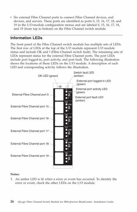
v Six external Fibre Channel ports to connect Fibre Channel devices, end
devices, and servers. These ports are identified as ports 0, 15, 16, 17, 18, and
19 in the I/O-module configuration menus and are labeled 0, 15, 16, 17, 18,
and 19 (from top to bottom) on the Fibre Channel switch module.
Information LEDs
The front panel of the Fibre Channel switch module has multiple sets of LEDs.
The first row of LEDs at the top of the I/O module represent I/O module
status and include OK and ! (Fibre Channel switch fault). The remaining sets of
LEDs represent status for the external Fibre Channel ports. The port LEDs
include port logged-in, port activity, and port fault. The following illustration
shows the locations of these LEDs on the I/O module. A description of each
LED and corresponding activity follows the illustration.
Switch fault LED(amber)
External port fault LED(amber)
External port activity LED(green)
External port logged-in LED(green)
OK LED (green)
External Fibre Channel port 0
External Fibre Channel port 15
External Fibre Channel port 16
External Fibre Channel port 17
External Fibre Channel port 18
External Fibre Channel port 19
0LOGTXRX
16
15
17
18
19
LOGTXRX
LOGTXRX
LOGTXRX
LOGTXRX
LOGTXRX
Notes:
1. An amber LED is lit when a error or event has occurred. To identify the
error or event, check the other LEDs on the I/O module.
26 QLogic Fibre Channel Switch Module for IBM Eserver BladeCenter: Installation Guide
2. An LED test occurs whenever the I/O module is turned on. All LEDs are
lit and remain lit for approximately 10 seconds during POST and then
return to a normal state.
3. For additional information about diagnostics, see the QLogic Fibre Channel
Switch Module for IBM Eserver BladeCenter Management Guide on the Support
CD.
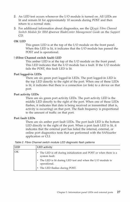
OK LED
This green LED is at the top of the I/O module on the front panel.
When this LED is lit, it indicates that the I/O module has passed the
POST and is operational.
! (Fibre Channel switch fault) LED
This amber LED is at the top of the I/O module on the front panel.
This LED indicates that the I/O module has a fault. If the I/O module
fails the POST, this fault LED is lit.
Port logged-in LEDs
There are six green port logged-in LEDs. The port logged-in LED is
the top LED directly to the right of the port. When one of these LEDs
is lit, it indicates that there is a connection (or link) to a device on that
port.
Port activity LEDs
There are six green port activity LEDs. The port activity LED is the
middle LED directly to the right of the port. When one of these LEDs
flashes, it indicates that data is being received or transmitted (that is,
activity is occurring) on that port. The flash frequency is proportional
to the amount of traffic on that port.
Port fault LEDs
There are six amber port fault LEDs. The port fault LED is the bottom
LED directly to the right of the port. When a port fault LED is lit, it
indicates that the external port has failed the internal, external, or
online port diagnostics tests that are performed with the SANsurfer
application or CLI.
Table 2. Fibre Channel switch module LED diagnostic flash patterns
LED LED activity
OK
v The LED is off during initialization and POST or when there is a
system fault.
v The LED is lit during LED test and when the I/O module is
operational.
v The LED flashes during POST.
Chapter 3. Information panel LEDs and external ports 27
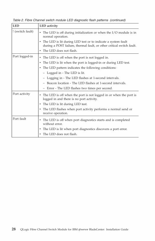
Table 2. Fibre Channel switch module LED diagnostic flash patterns (continued)
LED LED activity
! (switch fault)
v The LED is off during initialization or when the I/O module is in
normal operation.
v The LED is lit during LED test or to indicate a system fault
during a POST failure, thermal fault, or other critical switch fault.
v The LED does not flash.
Port logged-in
v The LED is off when the port is not logged in.
v The LED is lit when the port is logged-in or during LED test.
v The LED pattern indicates the following conditions:
– Logged in - The LED is lit.
– Logging in - The LED flashes at 1-second intervals.
– Beacon location - The LED flashes at 1-second intervals.
– Error - The LED flashes two times per second.
Port activity
v The LED is off when the port is not logged in or when the port is
logged in and there is no port activity.
v The LED is lit during LED test.
v The LED flashes when port activity performs a normal send or
receive operation.
Port fault
v The LED is off when port diagnostics starts and is completed
without error.
v The LED is lit when port diagnostics discovers a port error.
v The LED does not flash.
28 QLogic Fibre Channel Switch Module for IBM Eserver BladeCenter: Installation Guide

Chapter 4. Configuring the switch module through the
Telnet interface
The Fibre Channel switch module contains a Telnet server. This server enables
a Telnet client to establish a Telnet session with the Fibre Channel switch
module to retrieve information or to configure parameters using the
command-line interface (CLI). You can perform a variety of fabric and I/O
management tasks through an Ethernet connection using the CLI.
You can access the Telnet interface in two ways:
v In the BladeCenter management module Web interface
v In a command-line window on a network management workstation
For you to configure the switch module through the Telnet interface, the
Internet protocol (IP) address and subnet masks must be compatible, and the
following configuration settings in the management module must be enabled:
v External ports
v External management over all ports
For you to access a switch module from a network management workstation,
make sure that it is connected to an external BladeCenter management-module
Ethernet port.
To enable the configuration settings, in the management module Web interface,
click I/O Module Tasks ⇒ Management ⇒ Advanced Switch Management ⇒
Advanced Setup.
Note: Be sure to configure your switch module with the correct date and time
information. See steps 3 through 5 on page 33 for additional information
about setting the date and time of the switch module.
Important: Before you configure the I/O module, be sure that the management
modules in your BladeCenter unit are correctly configured. In addition, to
access and manage the I/O module from an external environment, you might
need to enable certain features, such as the external ports and external
management over all ports. For more information, see the applicable
BladeCenter Installation and User’s Guide documents on the IBM Support Web
site, http://www.ibm.com/support/. For more detailed information about
configuring the I/O module, see the QLogic Fibre Channel Switch Module for
IBM Eserver BladeCenter Management Guide on the Support CD.
In addition to reviewing the documentation that is described in “Related
documentation” on page 3, be sure to review the IBM Eserver BladeCenter
© Copyright IBM Corp. 2005 29
Planning and Installation Guide or the IBM Eserver BladeCenter T Planning and
Installation Guide at http://www.ibm.com/support/ on the World Wide Web
for information to help you prepare for system installation and configuration.
Notes:
v Throughout this document, the management-module Web-based user
interface is also known as the BladeCenter management-module Web
interface.
v Throughout this document, the user name is also known as the login name,
user identifier, or user ID for logging onto one or more of the following
interfaces or programs:
– BladeCenter management-module Web interface
– Telnet interface (this chapter)
– SANbrowser interface (Chapter 5, “Configuring the switch module using
the SANbrowser interface,” on page 35)
– SANsurfer application (Chapter 6, “Configuring the switch module
through the SANsurfer application,” on page 41)
v The sample screens that appear in this document might differ slightly from
the screens that are displayed by your system. Screen content varies based
on the type of BladeCenter unit that you are using and the options that are
installed.
Connecting to the Fibre Channel switch module
To use the Telnet program (in VT100 compatible terminal mode) to access and
control the I/O module, you must know the IP address for the I/O module
and have an existing network connection. If you need to obtain the IP address
for the I/O module or establish a network connection, contact your system or
network administrator. Be sure to use the correct IP address in the required
command.
Establishing a Telnet session through the management
module
Complete the following steps to establish a Telnet session through the
BladeCenter management module:
1. In your browser, in the address bar, type http://xxx.xxx.xxx.xxx, where
xxx.xxx.xxx.xxx is the IP address of the BladeCenter management-module
interface. Click GO or press Enter. The Enter Network Password window
opens.
Note: The default IP address for the BladeCenter management module is
192.168.70.125.
30 QLogic Fibre Channel Switch Module for IBM Eserver BladeCenter: Installation Guide
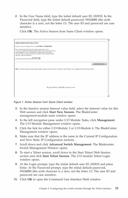
2. In the User Name field, type the initial default user ID, USERID. In the
Password field, type the initial default password, PASSW0RD (the sixth
character is a zero, not the letter O). The user ID and password are case
sensitive.
Click OK. The Active Session from Same Client window opens.
3. In the Inactive session timeout value field, select the timeout value for this
Web session and click Start New Session. The BladeCenter
management-module main window opens.
4. In the left navigation pane under I/O Module Tasks, click Management.
The I/O Module Management window opens.
5. Click the link for either I/O-Module 3 or I/O-Module 4. The BladeCenter
Management window opens.
6. Make sure that the IP address is the same in the Current IP Configuration
and New Static IP Configuration sections.
7. Scroll down and click Advanced Switch Management. The Bladecenter
Switch Management Window opens.
8. To start a Telnet session, scroll down to the Start Telnet/Web Session
section and click Start Telnet Session. The I/O module Telnet Login
window opens.
9. At the Login prompt, type the initial default user ID, USERID and press
Enter. At the Password prompt, type the initial default password,
PASSW0RD (the sixth character is a zero, not the letter O). The user ID and
password are case sensitive.
10. Click OK to open the Command Line Interface Shell window.
Figure 1. Active Session from Same Client window
Chapter 4. Configuring the switch module through the Telnet interface 31
To open online help, type help and press Enter.
Continue with “CLI command format” on page 34. For more information about
using the CLI, see the QLogic Fibre Channel Switch Module for IBM Eserver
BladeCenter Management Guide on the Support CD.
Establishing a Telnet session in a command-line window
You can access the switch module by IP-enabled devices that are connected to
the BladeCenter management module. An Ethernet connection to the
management-module external ports on the BladeCenter unit is required. For
more information, see the following documents on the IBM Support Web site,
at http://www.ibm.com/support/:
v BladeCenter unit Installation and User’s Guide
v BladeCenter Management Module Installation Guide
v IBM BladeCenter Management Module User’s Guide
To establish a Telnet session through the command-line interface, complete the
following steps:
Note: The IP addresses in the following step are the default IP address of the
I/O modules; if new IP addresses have been assigned to the I/O
modules, use these instead.
1. Open a command-line window on the network management workstation
and type one of the following commands and press Enter.
For I/O-module bay 3:
telnet 192.168.70.129
For I/O-module bay 4:
telnet 192.168.70.130
A command prompt window opens.
2. At the Login prompt, type the initial default user ID, USERID and press
Enter. At the Password prompt, type the initial default password, PASSW0RD
(the sixth character is a zero, not the letter O) and press Enter. The user ID
and password are case sensitive.
The Command Line Interface Shell window opens.
32 QLogic Fibre Channel Switch Module for IBM Eserver BladeCenter: Installation Guide

3. You must change the date and time of the switch module. Before you can
do this, you must obtain administrator privileges through the admin start
command.
Type admin start and press Enter.
4. Set the date and time of the switch module through the date command.
The syntax for this command is date MMDDhhmmCCYY, where:
MM is the month
DD is the day
hh is the hour in 24-hour format
mm is the minute
CC represents the century identifier
YY represents the last two numbers of the year
For example, the format for June 28, 2004 8:46 P.M. is date 062820462004.
Type the applicable date command and press Enter.
5. Use the admin end command to exit the administrator operating mode and
return to the standard operating mode.
Type admin end and press Enter.
Chapter 4. Configuring the switch module through the Telnet interface 33
For detailed information about using the admin start, date, and admin end
commands, see the QLogic Fibre Channel Switch Module for IBM Eserver
BladeCenter Management Guide on the Support CD.
CLI command format
The information in this section gives an overview of the CLI command format.
For detailed information about using CLI commands, see the QLogic Fibre
Channel Switch Module for IBM Eserver BladeCenter Management Guide on the
Support CD.
A command is followed by one or more keywords. The following rules apply
when typing keywords:
v Commands and keywords are lowercase and case sensitive.
v Required keyword values are shown in standard font: [value}. Optional
values are shown in italics [value].
v The underlined portion of each keyword indicates the abbreviated form that
can be used. For example, the Delete keyword can be abbreviated as Del.
The CLI command syntax is as follows:
v keyword
v keyword [value]
v keyword [value][value 2]
Items in square brackets ([ ]) can be changed by typing a new value. You can
use the Backspace and Delete keys to erase characters behind and in front of
the cursor.
34 QLogic Fibre Channel Switch Module for IBM Eserver BladeCenter: Installation Guide

Chapter 5. Configuring the switch module using the
SANbrowser interface
The switch module contains a Web server interface known as SANbrowser.
This server enables a Web-based client to establish a Web-interface session with
the Fibre Channel switch module to retrieve information or to configure
parameters using a Web browser. You can perform a variety of fabric and
switch-management tasks through an Ethernet connection using a Web
browser.
You can access the management-module Web interface in two ways:
v In the BladeCenter management-module Web interface
v Through a Web browser on a network-management workstation
SANbrowser is a graphical interface that requires a Web browser to view and
manage the switch. For information about system requirements and supported
Web browsers, see “System requirements” on page 42.
For you to configure the switch module through the Web interface, the IP
address and subnet masks must be compatible, and the following configuration
settings in the management module must be enabled:
v External ports
v External management over all ports
For you to access a switch module from a network management workstation,
make sure that it is connected to an external BladeCenter management-module
Ethernet port.
To enable the configuration settings in the management-module Web interface,
click Switch Tasks ⇒ Management ⇒ Advanced Switch Management ⇒
Advanced Setup.
Important: Before you configure the I/O module, be sure that the management
modules in your BladeCenter unit are correctly configured. In addition, to
access and manage the I/O module from an external environment, you might
need to enable certain features, such as the external ports and external
management over all ports. For more information, see the applicable
BladeCenter Installation and User’s Guide documents on the IBM Support Web
site, http://www.ibm.com/support/. For more detailed information about
configuring the I/O module, see the QLogic Fibre Channel Switch Module for
IBM Eserver BladeCenter Management Guide on the Support CD.
© Copyright IBM Corp. 2005 35
Notes:
v Throughout this document, the management-module Web-based user
interface is also known as the BladeCenter management-module Web
interface.
v Throughout this document, the user name is also known as the login name,
user identifier, or user ID for logging onto one or more of the following
interfaces or programs:
– BladeCenter management-module Web interface
– Telnet interface (Chapter 4, “Configuring the switch module through the
Telnet interface,” on page 29)
– SANbrowser interface (this chapter)
– SANsurfer application (Chapter 6, “Configuring the switch module
through the SANsurfer application,” on page 41)
v The sample screens that appear in this document might differ slightly from
the screens that are displayed by your system. Screen content varies based
on the type of BladeCenter unit that you are using and the options that are
installed.
Connecting to the switch module
For you to use the SANbrowser interface to access and control the switch
module, you must know the IP address for the switch module and have an
existing network connection. If you have to obtain the IP address for the
switch module or establish a network connection, contact your system or
network administrator.
Establishing a Web-interface session through the
management module
To establish a Web-interface session through the BladeCenter management
module, complete the following steps:
1. In your browser, in the address field, type http://xxx.xxx.xxx.xxx, where
xxx.xxx.xxx.xxx is the IP address of the BladeCenter management-module
interface. Click GO or press Enter. The Enter Network Password window
opens.
Note: The default IP address for the BladeCenter management module is
192.168.70.125.
2. In the User Name field, type the initial default user name, USERID. In the
Password field, type the initial default password, PASSW0RD (the sixth
character is a zero). The user name and password are case sensitive.
Click OK. The Active Session from Same Client window opens.
36 QLogic Fibre Channel Switch Module for IBM Eserver BladeCenter: Installation Guide
3. In the Inactive session timeout value field, select the timeout value for this
Web session and click Start New Session. The BladeCenter
management-module main window opens.
4. In the left navigation pane, under I/O Module Tasks, click Management.
The I/O Module Management window opens.
5. Click the link for either switch module 3 or switch module 4. The I/O
module management window opens.
6. Make sure that the IP address is the same in the Current IP Configuration
and New Static IP Configuration sections.
7. Scroll down and click Advanced Switch Management. The BladeCenter
Management window opens.
8. To start a Web-interface session, scroll down to the Start Telnet/Web
Session section and click Start Web Session.
The SANbrowser certificate check window opens.
Note: SANbrowser only supports single switch management per session.
9. Click Yes to accept the certificate.
The Initial Start view of the SANbrowser interface window opens.
10. Select Open existing fabric and click Proceed. The SANbrowser Add a
New Fabric window opens.
11. In the IP Address field, type the IP address of the switch to be accessed.
12. In the Login Name field, type the initial default user name, USERID. In the
Password field, type the initial default password, PASSW0RD (the sixth
character is a zero, not the letter O). The login name and password are
case sensitive.
13. Click the Add Fabric button.
14. If the switch module is not configured for a secure connection, click OK.
The SANbrowser topology window opens.
15. In the Switch Pane, click the Entry Handle to view the available switches
in the fabric.
Chapter 5. Configuring the switch module using the SANbrowser interface 37

16. Click the switch labeled FCSM xxx. The SANbrowser Faceplate window
opens.
For more information about using the SANbrowser interface, see the QLogic
Fibre Channel Switch Module for IBM Eserver BladeCenter Management Guide on
the Support CD.
Establishing a Web-interface session through a Web
browser
You can access the switch module by IP-enabled devices that are connected to
the BladeCenter management module. An Ethernet connection to the
management-module external ports on the BladeCenter unit is required. For
more information, see the following documents on the IBM Support Web site,
http://www.ibm.com/support/:
v BladeCenter unit Installation and User’s Guide
v BladeCenter Management Module Installation Guide
v IBM BladeCenter Management Module User’s Guide
Complete the following steps to establish a Web-interface session through a
Web browser:
1. Open a supported Web browser on the network-management workstation.
2. Type one of the following Web addresses in the address field and press
Enter. These Web addresses contain default IP addresses.
Figure 2. SANbrowser Faceplate window
38 QLogic Fibre Channel Switch Module for IBM Eserver BladeCenter: Installation Guide

For I/O bay 3:
http://192.168.70.129
For I/O bay 4:
http://192.168.70.130
3. Click Yes to accept the certificate.
The Initial Start view of the SANbrowser interface window opens.
4. Select Open existing fabric and click Proceed.
The SANbrowser Add a New Fabric window opens.
5. In the IP Address field, type the IP address of the switch to be accessed.
6. In the Login Name field, type the initial default user name, USERID. In the
Password field, type the initial default password, PASSW0RD (the sixth
character is a zero, not the letter O). The login name and password are
case sensitive.
7. Click the Add Fabric button.
8. If the switch module is not configured for a secure connection, click OK.
The SANbrowser topology window opens.
9. In the Switch Pane, click the Entry Handle to view the available switches
in the fabric.
10. Click the switch labeled FCSM xxx. The SANbrowser Faceplate window
opens, as shown in Figure 2 on page 38.
For more information about using the SANbrowser interface, see the QLogic
Fibre Channel Switch Module for IBM Eserver BladeCenter Management Guide on
the Support CD.
Chapter 5. Configuring the switch module using the SANbrowser interface 39

40 QLogic Fibre Channel Switch Module for IBM Eserver BladeCenter: Installation Guide
Chapter 6. Configuring the switch module through the
SANsurfer application
You can use the SANsurfer application to access and configure the I/O
modules. The SANsurfer application can be installed on a network
management workstation, which is either a BladeCenter blade server or an
external network management workstation configured with one of the
operating systems described in “System requirements” on page 42.
This chapter lists the system requirements and explains how to install the
SANsurfer application. In addition, this chapter describes two basic windows
that you will use to manage your fabrics and I/O modules: Topology and
Faceplate.
Important: Before you configure the I/O module, be sure that the management
modules in your BladeCenter unit are correctly configured. In addition, to
access and manage the I/O module from an external environment, you might
need to enable certain features, such as the external ports and external
management over all ports. For more information, see the applicable
BladeCenter Installation and User’s Guide documents on the IBM Support Web
site, http://www.ibm.com/support/. For more detailed information about
configuring the I/O module, see the QLogic Fibre Channel Switch Module for
IBM Eserver BladeCenter Management Guide on the Support CD.
In addition to reviewing the documentation that is described in “Related
documentation” on page 3, be sure to review the IBM Eserver BladeCenter
Planning and Installation Guide or the IBM Eserver BladeCenter T Planning and
Installation Guide at http://www.ibm.com/support/ on the World Wide Web
for information to help you prepare for system installation and configuration.
Notes:
v Throughout this document, the management-module Web-based user
interface is also known as the BladeCenter management-module Web
interface.
v Throughout this document, the user name is also known as the login name,
user identifier, or user ID for logging onto one or more of the following
interfaces or programs:
– BladeCenter management-module Web interface
– Telnet interface (Chapter 4, “Configuring the switch module through the
Telnet interface,” on page 29)
– SANbrowser interface (Chapter 5, “Configuring the switch module using
the SANbrowser interface,” on page 35)
– SANsurfer application (this chapter)
© Copyright IBM Corp. 2005 41

v The sample screens that appear in this document might differ slightly from
the screens that are displayed by your system. Screen content varies based
on the type of BladeCenter unit that you are using and the options that are
installed.
System requirements
Before you install the SANsurfer application, be sure that your network
management workstation has the following hardware and software.
Table 3. Network management workstation requirements
Operating system
v Microsoft® Windows® 2000
v Microsoft Windows 2003
v Red Hat Linux Advanced Server
v Red Hat Linux
v SUSE LINUX
Memory 256 MB minimum
Disk space 150 MB for each installation
Processor 500 MHz or faster
Hardware CD-ROM drive, 10/100/1000 Base-T Ethernet port
Internet browser
v Microsoft Internet Explorer
v Mozilla
v Netscape Navigator
Note: See the readme file that comes with the SANsurfer application for
information about supported operating system versions.
Use the applicable procedure in the following sections to install the SANsurfer
application on your network management workstation.
42 QLogic Fibre Channel Switch Module for IBM Eserver BladeCenter: Installation Guide

Installing the SANsurfer application on a Microsoft Windows
2000 or Microsoft Windows 2003 platform
Note: See the readme file that comes with the SANsurfer application for
information about supported operating system versions.
To install the SANsurfer application on a network management workstation
that is configured with Microsoft Windows 2000 or Microsoft Windows 2003,
complete the following steps:
1. If your network management workstation is a blade server, associate the
CD-ROM drive with the blade server by pressing the CD/diskette/USB
select button on the blade server. For the location of the CD/diskette/USB
button, see the documentation that comes with the blade server. The LED
on this component flashes while the request is being processed, then is
steady when the ownership of the CD-ROM drive is transferred to the
blade server.
2. If your network management workstation is a blade server, associate the
keyboard port, mouse port, and video port with the blade server by
pressing the keyboard/mouse/video select button. The LED on this
component flashes while the request is processed, then is steady when the
ownership of the keyboard, mouse and video is transferred to the blade
server.
Note: To install graphically on a blade server without local video
capability, the video component must be exported to a remote
machine or device that supports video functionality.
3. Close all open programs. Insert the Support CD into the CD-ROM drive.
4. Open Windows Explorer and double-click the CD-ROM drive letter.
5. To install the SANsurfer application, use one of the following methods,
where x.xx.xx is the SANsurfer application version number:
v To install from the CD, go to the Windows directory on the CD and
double-click Windowsx.xx.xx.exe. Follow the SANsurfer application
installation instructions.
v To copy and install from the hard disk drive, complete the following
steps:
a. Specify a location and save the Windowsx.xx.xx.exe file.
b. Click Save.
c. Double-click Windowsx.xx.xx.exe.
d. Follow the SANsurfer application installation instructions.
6. When the installation is completed, use one of the following methods to
start the SANsurfer application:
v Double-click the SANsurfer application shortcut.
Chapter 6. Configuring the switch module through the SANsurfer application 43
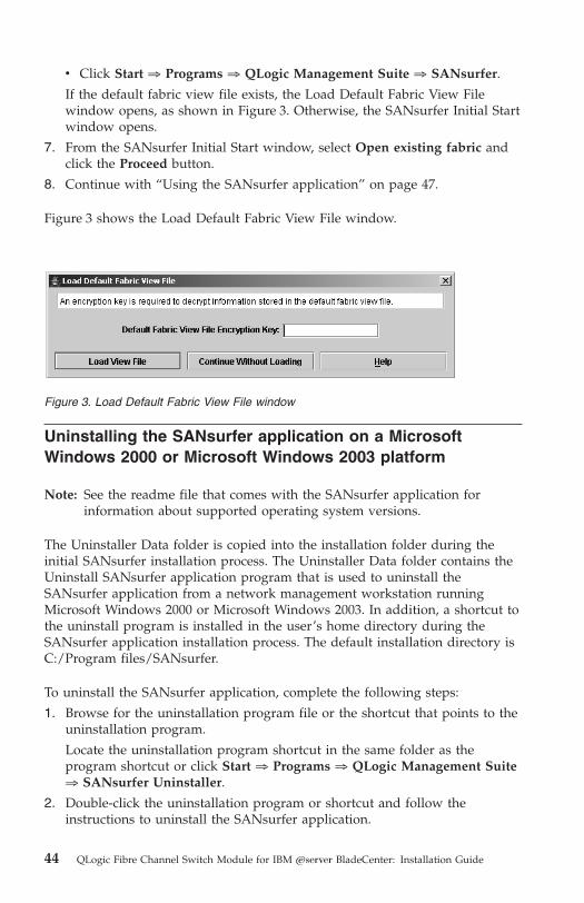
v Click Start ⇒ Programs ⇒ QLogic Management Suite ⇒ SANsurfer.
If the default fabric view file exists, the Load Default Fabric View File
window opens, as shown in Figure 3. Otherwise, the SANsurfer Initial Start
window opens.
7. From the SANsurfer Initial Start window, select Open existing fabric and
click the Proceed button.
8. Continue with “Using the SANsurfer application” on page 47.
Figure 3 shows the Load Default Fabric View File window.
Uninstalling the SANsurfer application on a Microsoft
Windows 2000 or Microsoft Windows 2003 platform
Note: See the readme file that comes with the SANsurfer application for
information about supported operating system versions.
The Uninstaller Data folder is copied into the installation folder during the
initial SANsurfer installation process. The Uninstaller Data folder contains the
Uninstall SANsurfer application program that is used to uninstall the
SANsurfer application from a network management workstation running
Microsoft Windows 2000 or Microsoft Windows 2003. In addition, a shortcut to
the uninstall program is installed in the user’s home directory during the
SANsurfer application installation process. The default installation directory is
C:/Program files/SANsurfer.
To uninstall the SANsurfer application, complete the following steps:
1. Browse for the uninstallation program file or the shortcut that points to the
uninstallation program.
Locate the uninstallation program shortcut in the same folder as the
program shortcut or click Start ⇒ Programs ⇒ QLogic Management Suite
⇒ SANsurfer Uninstaller.
2. Double-click the uninstallation program or shortcut and follow the
instructions to uninstall the SANsurfer application.
Figure 3. Load Default Fabric View File window
44 QLogic Fibre Channel Switch Module for IBM Eserver BladeCenter: Installation Guide
Installing the SANsurfer application on Red Hat Linux or
SUSE LINUX platform
Note: See the readme file that comes with the SANsurfer application for
information about supported operating system versions.
To install the SANsurfer application on a network management workstation
that is configured with Red Hat Linux® or SUSE LINUX, complete the
following steps:
1. If your network management workstation is a blade server, associate the
CD-ROM drive with the blade server by pressing the CD/diskette/USB
select button on the blade server. For the location of the CD/diskette/USB
button, see the documentation that comes with the blade server. The LED
on this component flashes while the request is being processed, then is
steady when the ownership of the CD-ROM drive is transferred to the
blade server.
2. If your network management workstation is a blade server, associate the
keyboard port, mouse port, and video port with the blade server by
pressing the keyboard/mouse/video select button. The LED on this
component flashes while the request is processed, then is steady when the
ownership of the keyboard, mouse and video is transferred to the blade
server.
Note: To install graphically on a blade server without local video
capability, the video component must be exported to a remote
machine or device that supports video functionality.
3. Close all open programs. Insert the Support CD into the CD-ROM drive.
4. Open an xterm or other terminal window.
5. Mount the CD. From a shell command-line prompt, type one of the
following commands and press Enter:
v For the Red Hat Linux operating system:
mount /mnt/cdrom
v For the SUSE LINUX operating system:
mount/media/cdrom
6. To install the SANsurfer application, use one of the following methods,
where x.xx.xx is the SANsurfer version number:
v To install from the CD, go to the Linux directory and type:
sh Linux_x.xx.xx.bin
Follow the SANsurfer application installation instructions.
Chapter 6. Configuring the switch module through the SANsurfer application 45

v To copy and install from your hard disk drive, complete the following
steps:
a. Type:
cp /Linux_x.xx.xx.bin /[directory]/
Where [directory] is the location of the files that you want to copy.
b. Open a terminal window for the directory in which the
Linux_x.xx.xx.bin file was saved.
c. Type:
sh Linux_x.xx.xx.bin
d. Follow the SANsurfer installation instructions.
7. To start the SANsurfer application after the installation is completed, from
a command prompt, type the following command and press Enter:
sh /opt/QLogic_Corporation/SANsurfer/
SANsurfer
If the default fabric view file exists, the Load Default Fabric View File
window opens. Otherwise, the SANsurfer Initial Start window opens.
8. From the SANsurfer Initial Start window, select Open existing fabric and
click the Proceed button.
9. Continue with “Using the SANsurfer application” on page 47.
Uninstalling the SANsurfer application from a Linux
operating system
Note: See the readme file that comes with the SANsurfer application for
information about supported operating system versions.
The Uninstaller Data folder is copied into the installation folder during the
initial SANsurfer installation process. The Uninstaller Data folder contains the
Uninstall SANsurfer program that is used to uninstall the SANsurfer
application from a network management workstation running Red Hat Linux
or SUSE LINUX. In addition, a shortcut to the uninstallation program is
installed in the user’s home directory during the SANsurfer installation
process. The default installation directory is
/opt/QLogic_Corporation/SANsurfer/.
To uninstall the SANsurfer application, complete the following steps:
1. At the command prompt, type the following command and press Enter:
# cd /opt/QLogic_Corporation/SANsurfer/uninstalldata/
2. At the command prompt, type the following command and press Enter:
#sh SANsurferuninstaller
46 QLogic Fibre Channel Switch Module for IBM Eserver BladeCenter: Installation Guide

Using the SANsurfer application
Use the following procedures to start the SANsurfer application and complete
the following tasks:
v Start the SANsurfer application and add a new fabric
v Change the encryption key for the default fabric view
v Set user preferences
v Access online help
v Save the default fabric
v Exit the SANsurfer application
Starting the SANsurfer application and adding a new fabric
When you have successfully installed the SANsurfer application and the
default fabric view does not exist, the SANsurfer - Topology window (referred
to as the Topology window) opens.
If the default fabric view file exists, the Load Default Fabric View File window
opens. To start the SANsurfer application and add a new fabric, complete the
following steps:
1. At the Default file encryption key prompt, type the password and click
Load View File.
The SANsurfer application starts, and any previously saved set of fabrics is
displayed. If no set of fabrics has been saved previously, click Continue
Without Loading to open an empty fabric view.
The Topology window opens.
2. Click Add. The Add a New Fabric window opens.
3. In the Fabric name field, type a fabric name.
4. In the IP address field, type the IP address of the I/O module.
5. In the Login name field, type the initial default user ID, USERID. In the
Password field, type the initial default password, PASSW0RD (the sixth
character is a zero, not the letter O). The user ID and password are case
sensitive.
6. Click Add Fabric.
7. If the switch module is not configured for a secure connection, click OK.
For information about managing fabrics, see the QLogic Fibre Channel Switch
Module for IBM Eserver BladeCenter Management Guide on the Support CD.
Chapter 6. Configuring the switch module through the SANsurfer application 47

Changing the encryption key for the default fabric view
To change the encryption key for the default fabric view file, complete the
following steps:
1. In the Topology window, click File ⇒ Save Default Fabric View File. The
Save Default Fabric View File window opens.
2. In the Default fabric view file encryption key field, type the new password.
3. In the Re-enter encryption key to confirm field, type the same password
again.
4. Click OK to save your changes.
Note: If you lose the encryption key for the account, contact IBM Support
(see Appendix A, “Getting help and technical assistance,” on page
57).
Setting user preferences
Use the Preferences window to perform the following tasks:
v Change the location of the working directory that you will use to save files.
v Change the location of the browser used to view the online help.
v Enable or disable the default view file auto save and load feature. See
“Using the SANsurfer application” on page 47 for more information about
the default fabric view file.
v Select the default port view when opening the SANsurfer application
Faceplate window (referred to as the Faceplate window). See the QLogic Fibre
Channel Switch Module for IBM Eserver BladeCenter Management Guide on the
Support CD for more information about port views.
v Enable or disable the Event Browser. See the QLogic Fibre Channel Switch
Module for IBM Eserver BladeCenter Management Guide on the Support CD for
more information about the Event Browser.
v Enable or disable the initial startup dialog. See the QLogic Fibre Channel
Switch Module for IBM Eserver BladeCenter Management Guide on the Support
CD for more information about the initial startup dialog.
To set user preferences for your SANsurfer sessions from the Faceplate
window, complete the following steps:
1. Click File ⇒ Preferences. The Preferences window opens.
2. Type or browse to the paths to the working directory and browser.
3. In the Application-wide Options area of the window, complete the
following steps:
a. In the View file auto save and load field, select Enabled or Disabled.
b. In the Display initial startup dialog field, select Enabled or Disabled.
c. In the Display dialog when making non-secure connections field, select
Enabled or Disabled.
48 QLogic Fibre Channel Switch Module for IBM Eserver BladeCenter: Installation Guide

d. In the Event browser field, select Enabled or Disabled.
e. In the Preferred Initial Port View field, select the port view mode for the
Faceplate window.
4. Click OK to save your changes.
Using online help
Online help is available for the SANsurfer application. You can access online
help through the following methods:
v From the SANsurfer window menu bar, click Help ⇒ Help Topics.
v From the SANsurfer window toolbar, click Help.
To view the SANsurfer software version and copyright information, click Help
⇒ About.
Exiting the SANsurfer application
When you exit the SANsurfer application, the current fabric view is encrypted
and saved to the default fabric view file (fc_view.dft). An encryption key is
required to encrypt and save the default fabric view file the first time you exit
the SANsurfer application. When you exit subsequent sessions, the SANsurfer
application closes and saves the default fabric view file automatically without
requiring a encryption key.
In your next session, the SANsurfer application opens the default fabric view
file automatically after you type the encryption key. To prevent the SANsurfer
application from automatically saving the default fabric view file each time
that you exit a session, select Disabled in the View file auto save and load
field (it is set to Enabled by default). See “Setting user preferences” on page 48
for more information.
To exit a SANsurfer session, complete the following steps:
1. From the Faceplate window, click File ⇒ Exit. The Save Default Fabric
View File window opens.
2. When you are prompted to type an encryption key with which to protect
the default fabric view file, complete one of the following tasks:
v To save the current set of fabrics in the default fabric view file
(fc_view.dft) in the working directory, type an encryption key and click
Save View File.
Note: If the default fabric view file was saved with an encryption key,
the next time that you open the SANsurfer application, you will
be prompted for the encryption key in the Load Default Fabric
View File window. The fabric window opens after you type the
encryption key.
Chapter 6. Configuring the switch module through the SANsurfer application 49
v Click Cancel to cancel the exit operation.
SANsurfer Topology and Faceplate windows
The SANsurfer application provides two basic windows for you to manage the
fabric and switch modules. The windows are called Topology and Faceplate.
Both windows share the following common elements:
Menu bar: The menus and the items offered in them vary depending on which
window is open. For example, the port menu and many of the switch menu
selections are displayed only in the Faceplate window. Menu items have a gray
background.
In addition to the menu bar, each window has context-sensitive menus that
open when you right-click in the graphic window. See the information about
opening the Faceplate window and pop-up window in the QLogic Fibre Channel
Switch Module for IBM Eserver BladeCenter Management Guide on the Support
CD.
Toolbar: The toolbar consists of a row of graphical buttons that you can use to
access SANsurfer functions. The toolbar buttons are an alternative method to
using the menu bar.
Fabric tree: The fabric tree, shown in the Switch pane, lists the managed
fabrics and their associated switches. The pane width can be adjusted by
clicking and dragging the moveable border. An entry handle to the left of an
entry in the tree indicates that the entry can be expanded. Click this handle or
double-click the entry to expand or contract a fabric tree entry. A fabric entry
expands to show its member switches.
You can use the fabric tree to access any fabric or switch using the Topology or
Faceplate window. You can click a fabric entry to open the Topology window
from the fabric tree. You can click a switch entry to open the Faceplate window
from the fabric tree.
Graphic window: The graphic window presents graphic information about
fabrics and switches such as the fabric topology and the switch faceplate. You
can adjust the window length by clicking and dragging the window border
that it shares with the data window.
Data window and tabs: A table of data and statistics associated with the
selected tab is displayed in the data window. Use the scroll bar to browse
through the data. The window length can be adjusted by clicking and dragging
the border that it shares with the graphic window. The data window tabs
present options for the type of information that is displayed in the data
window. These options vary depending on the tab that you select.
50 QLogic Fibre Channel Switch Module for IBM Eserver BladeCenter: Installation Guide

Working status indicator: The working status indicator is in the lower-right
corner of the SANsurfer application window. The indicator is displayed when
the network management workstation is exchanging information with the
fabric. As conditions change, the fabric forwards this information to the
network management workstation where it is displayed in the various
windows.
I/O modules that are enabled, and the connections between I/O modules, are
displayed in the Topology window, as shown in the following illustration.
A single switch and its active ports are displayed in the Faceplate window. The
Faceplate window for I/O modules installed in a BladeCenter unit is shown in
the following figure.
Chapter 6. Configuring the switch module through the SANsurfer application 51
The Faceplate window for I/O modules installed in a BladeCenter T unit is
shown in the following figure.
The fabric tree, in the Switch pane, lists the managed fabrics and their
switches. You can adjust the window by clicking and dragging the moveable
window border. An entry handle at the left of the entry in the tree indicates
that the entry can be expanded. When you click the handle or double-click the
52 QLogic Fibre Channel Switch Module for IBM Eserver BladeCenter: Installation Guide
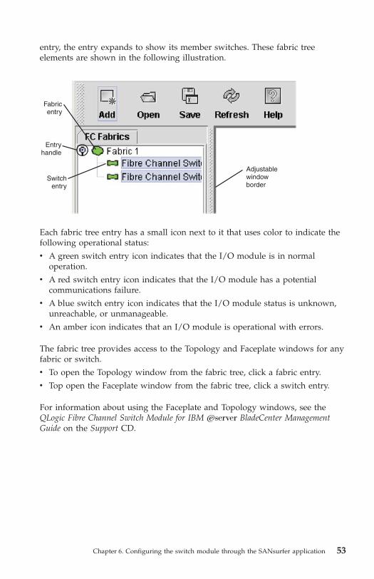
entry, the entry expands to show its member switches. These fabric tree
elements are shown in the following illustration.
Each fabric tree entry has a small icon next to it that uses color to indicate the
following operational status:
v A green switch entry icon indicates that the I/O module is in normal
operation.
v A red switch entry icon indicates that the I/O module has a potential
communications failure.
v A blue switch entry icon indicates that the I/O module status is unknown,
unreachable, or unmanageable.
v An amber icon indicates that an I/O module is operational with errors.
The fabric tree provides access to the Topology and Faceplate windows for any
fabric or switch.
v To open the Topology window from the fabric tree, click a fabric entry.
v Top open the Faceplate window from the fabric tree, click a switch entry.
For information about using the Faceplate and Topology windows, see the
QLogic Fibre Channel Switch Module for IBM Eserver BladeCenter Management
Guide on the Support CD.
Fabricentry
Entryhandle
Adjustablewindowborder
Switchentry
Chapter 6. Configuring the switch module through the SANsurfer application 53

54 QLogic Fibre Channel Switch Module for IBM Eserver BladeCenter: Installation Guide

Chapter 7. Expanding the functionality of the switch
module
You can expand the functionality of the switch module with the following
optional software features.
Table 4. Optional software features
License function Description
McDATA Mode Activation Enables the QLogic switch module to be
upgraded to support McDATA Mode Fabric
Interoperability.
McDATA SANtegrity Enhanced
Activation for IBM Eserver BladeCenter
Note: McDATA mode must be activated to
use with McDATA SANtegrity Enhanced
Activation for IBM Eserver BladeCenter.
Includes the following functions:
v McDATA SANtegrity Binding
The binding function helps to prevent
problems that might arise due to
inadvertently generating an incorrect
configuration.
v McDATA SANtegrity Authentication
The authentication function helps to
provide protection from WWN spoofing
or malicious users.
10-port Activation key Upgrades the switch module from 7 internal
ports and 3 external ports to 14 internal
ports and 6 external ports. This option is
only available for the 10-port switch
module.
Purchasing the optional software feature
To activate and use these optional software features, you must purchase the
corresponding software licenses. For information about these features and their
availability, see the documentation at http://www.ibm.com/support/.
To purchase and obtain a software license for an optional feature, go to
http://www.ibm.com/bladecenter/; then click on Switch modules or call IBM.
In the U.S. and Canada, call 1-800-IBM-SERV (1-800-426-7378). For all other
countries, go to http://www.ibm.com/planetwide/ for support telephone
numbers. After you purchase the feature, see the instructions that came with it.
Before you can expand the functionality of the switch module and install a
new software license, you must determine the product serial number of the
© Copyright IBM Corp. 2005 55
switch module. Use the Telnet program to log in to the switch module as
described in Chapter 5, “Configuring the switch module using the SANbrowser
interface,” on page 35, and run the show version command to determine the
value of the Chassis Serial Number data field. Record the serial number for
future reference; for example, 11S32R1793ZJ1ZC846H073. For information about
the show version command, see the QLogic Fibre Channel Switch Module for IBM
Eserver BladeCenter Management Guide at http://www.ibm.com/support/ or
on the Support CD.
Installing the optional software feature
To install an optional software feature on the switch, you must add the
corresponding software license to the list of software features for the switch.
Use the Telnet program to log in to the switch module as described in
Chapter 5, “Configuring the switch module using the SANbrowser interface,”
on page 35, and run the feature add key command, where key is the license
key for the new feature. For information about this command, see the QLogic
Fibre Channel Switch Module for IBM Eserver BladeCenter Management Guide at
http://www.ibm.com/support/ or on the Support CD.
To make sure that the software license has been successfully added to the
switch key, run the feature log command. For information about this
command, see the QLogic Fibre Channel Switch Module for IBM Eserver
BladeCenter Management Guide at http://www.ibm.com/support/ or on the
Support CD.
56 QLogic Fibre Channel Switch Module for IBM Eserver BladeCenter: Installation Guide

Appendix A. Getting help and technical assistance
If you need help, service, or technical assistance or just want more information
about IBM products, you will find a wide variety of sources available from
IBM to assist you. This appendix contains information about where to go for
additional information about IBM and IBM products, what to do if you
experience a problem with your Eserver
® or IntelliStation® system or optional
device, and whom to call for service, if it is necessary.
Before you call
Before you call, make sure that you have taken these steps to try to solve the
problem yourself:
v Check all cables to make sure that they are connected.
v Check the power switches to make sure that the system and any optional
devices are turned on.
v Use the troubleshooting information in your system documentation, and use
the diagnostic tools that come with your system. Information about
diagnostic tools is in the Hardware Maintenance Manual and Troubleshooting
Guide or Problem Determination and Service Guide on the IBM Documentation
CD that comes with your system.
Note: For some IntelliStation models, the Hardware Maintenance Manual and
Troubleshooting Guide is available only from the IBM support Web site.
v Go to the IBM support Web site at http://www.ibm.com/support/ to check
for technical information, hints, tips, and new device drivers or to submit a
request for information.
You can solve many problems without outside assistance by following the
troubleshooting procedures that IBM provides in the online help or in the
documentation that is provided with your IBM product. The documentation
that comes with Eserver and IntelliStation systems also describes the
diagnostic tests that you can perform. Most Eserver and IntelliStation systems,
operating systems, and programs come with documentation that contains
troubleshooting procedures and explanations of error messages and error
codes. If you suspect a software problem, see the documentation for the
operating system or program.
© Copyright IBM Corp. 2005 57
Using the documentation
Information about your IBM Eserver or IntelliStation system and preinstalled
software, if any, or optional device is available in the documentation that
comes with the product. That documentation can include printed documents,
online documents, readme files, and help files. See the troubleshooting
information in your system documentation for instructions for using the
diagnostic programs. The troubleshooting information or the diagnostic
programs might tell you that you need additional or updated device drivers or
other software. IBM maintains pages on the World Wide Web where you can
get the latest technical information and download device drivers and updates.
To access these pages, go to http://www.ibm.com/support/ and follow the
instructions. Also, some documents are available through the IBM Publications
Ordering System at
http://www.elink.ibmlink.ibm.com/public/applications/publications/
cgibin/pbi.cgi.
Getting help and information from the World Wide Web
On the World Wide Web, the IBM Web site has up-to-date information about
IBM Eserver and IntelliStation systems, optional devices, services, and
support. The address for IBM xSeries® and BladeCenter information is
http://www.ibm.com/eserver/xseries/. The address for IBM IntelliStation
information is http://www.ibm.com/intellistation/.
You can find service information for IBM systems and optional devices at
http://www.ibm.com/support/.
Software service and support
Through IBM Support Line, you can get telephone assistance, for a fee, with
usage, configuration, and software problems with xSeries servers, BladeCenter
products, IntelliStation workstations, and appliances. For information about
which products are supported by Support Line in your country or region, see
http://www.ibm.com/services/sl/products/.
For more information about Support Line and other IBM services, see
http://www.ibm.com/services/, or see http://www.ibm.com/planetwide/ for
support telephone numbers. In the U.S. and Canada, call 1-800-IBM-SERV
(1-800-426-7378).
58 QLogic Fibre Channel Switch Module for IBM Eserver BladeCenter: Installation Guide

Hardware service and support
You can receive hardware service through IBM Services or through your IBM
reseller, if your reseller is authorized by IBM to provide warranty service. See
http://www.ibm.com/planetwide/ for support telephone numbers, or in the
U.S. and Canada, call 1-800-IBM-SERV (1-800-426-7378).
In the U.S. and Canada, hardware service and support is available 24 hours a
day, 7 days a week. In the U.K., these services are available Monday through
Friday, from 9 a.m. to 6 p.m.
Appendix A. Getting help and technical assistance 59

60 QLogic Fibre Channel Switch Module for IBM Eserver BladeCenter: Installation Guide
Appendix B. Warranty information
IBM Statement of Limited Warranty Z125-4753-08 04/2004
Part 1 - General Terms
Part 1 - General Terms
This Statement of Limited Warranty includes Part 1 - General Terms, Part 2 -
Country-unique Terms, and Part 3 - Warranty Information. The terms of Part 2
replace or modify those of Part 1. The warranties provided by IBM in this Statement
of Limited Warranty apply only to Machines you purchase for your use, and not for
resale. The term “Machine” means an IBM machine, its features, conversions,
upgrades, elements, or accessories, or any combination of them. The term “Machine”
does not include any software programs, whether pre-loaded with the Machine,
installed subsequently or otherwise. Nothing in this Statement of Limited
Warranty affects any statutory rights of consumers that cannot be waived or
limited by contract.
What this Warranty Covers
IBM warrants that each Machine 1) is free from defects in materials and
workmanship and 2) conforms to IBM’s Official Published Specifications
(“Specifications”) which are available on request. The warranty period for the
Machine starts on the original Date of Installation and is specified in Part 3 -
Warranty Information. The date on your invoice or sales receipt is the Date of
Installation unless IBM or your reseller informs you otherwise. Many features,
conversions, or upgrades involve the removal of parts and their return to IBM.
A part that replaces a removed part will assume the warranty service status of
the removed part. Unless IBM specifies otherwise, these warranties apply only
in the country or region in which you purchased the Machine.
© Copyright IBM Corp. 2005 61
THESE WARRANTIES ARE YOUR EXCLUSIVE WARRANTIES AND
REPLACE ALL OTHER WARRANTIES OR CONDITIONS, EXPRESS OR
IMPLIED, INCLUDING, BUT NOT LIMITED TO, THE IMPLIED
WARRANTIES OR CONDITIONS OF MERCHANTABILITY AND FITNESS
FOR A PARTICULAR PURPOSE. SOME STATES OR JURISDICTIONS DO
NOT ALLOW THE EXCLUSION OF EXPRESS OR IMPLIED
WARRANTIES, SO THE ABOVE EXCLUSION MAY NOT APPLY TO YOU.
IN THAT EVENT, SUCH WARRANTIES ARE LIMITED IN DURATION TO
THE WARRANTY PERIOD. NO WARRANTIES APPLY AFTER THAT
PERIOD. SOME STATES OR JURISDICTIONS DO NOT ALLOW
LIMITATIONS ON HOW LONG AN IMPLIED WARRANTY LASTS, SO
THE ABOVE LIMITATION MAY NOT APPLY TO YOU.
What this Warranty Does not Cover
This warranty does not cover the following:
v any software programs, whether pre-loaded or shipped with the Machine,
or installed subsequently;
v failure resulting from misuse (including but not limited to use of any
Machine capacity or capability, other than that authorized by IBM in
writing), accident, modification, unsuitable physical or operating
environment, or improper maintenance by you;
v failure caused by a product for which IBM is not responsible; and
v any non-IBM products, including those that IBM may procure and provide
with or integrate into an IBM Machine at your request.
The warranty is voided by removal or alteration of identification labels on the
Machine or its parts.
IBM does not warrant uninterrupted or error-free operation of a Machine.
Any technical or other support provided for a Machine under warranty, such
as assistance with “how-to” questions and those regarding Machine set-up and
installation, is provided WITHOUT WARRANTIES OF ANY KIND.
How to Obtain Warranty Service
If the Machine does not function as warranted during the warranty period,
contact IBM or your reseller to obtain warranty service. If you do not register
the Machine with IBM, you may be required to present proof of purchase as
evidence of your entitlement to warranty service.
62 QLogic Fibre Channel Switch Module for IBM Eserver BladeCenter: Installation Guide

What IBM Will Do to Correct Problems
When you contact IBM for service, you must follow the problem determination
and resolution procedures that IBM specifies. An initial diagnosis of your
problem can be made either by a technician over the telephone or electronically
by access to an IBM website.
The type of warranty service applicable to your Machine is specified in Part 3 -
Warranty Information.
You are responsible for downloading and installing designated Machine Code
(microcode, basic input/output system code (called “BIOS”), utility programs,
device drivers, and diagnostics delivered with an IBM Machine) and other
software updates from an IBM Internet Web site or from other electronic
media, and following the instructions that IBM provides.
If your problem can be resolved with a Customer Replaceable Unit (“CRU”)
(e.g., keyboard, mouse, speaker, memory, hard disk drive), IBM will ship the
CRU to you for you to install.
If the Machine does not function as warranted during the warranty period and
your problem cannot be resolved over the telephone or electronically, through
your application of Machine Code or software updates, or with a CRU, IBM or
your reseller, if approved by IBM to provide warranty service, will either, at its
discretion, 1) repair it to make it function as warranted, or 2) replace it with
one that is at least functionally equivalent. If IBM is unable to do either, you
may return the Machine to your place of purchase and your money will be
refunded.
IBM or your reseller will also manage and install selected engineering changes
that apply to the Machine.
Exchange of a Machine or Part
When the warranty service involves the exchange of a Machine or part, the
item IBM or your reseller replaces becomes its property and the replacement
becomes yours. You represent that all removed items are genuine and
unaltered. The replacement may not be new, but will be in good working order
and at least functionally equivalent to the item replaced. The replacement
assumes the warranty service status of the replaced item.
Appendix B. Warranty information 63
Your Additional Responsibilities
Before IBM or your reseller exchanges a Machine or part, you agree to remove
all features, parts, options, alterations, and attachments not under warranty
service.
You also agree to:
1. ensure that the Machine is free of any legal obligations or restrictions that
prevent its exchange;
2. obtain authorization from the owner to have IBM or your reseller service a
Machine that you do not own; and
3. where applicable, before service is provided:
a. follow the service request procedures that IBM or your reseller
provides;
b. backup or secure all programs, data, and funds contained in the
Machine;
c. provide IBM or your reseller with sufficient, free, and safe access to
your facilities to permit IBM to fulfill its obligations; and
d. inform IBM or your reseller of changes in the Machine’s location.4. (a) ensure all information about identified or identifiable individuals
(Personal Data) is deleted from the Machine (to the extent technically
possible), (b) allow IBM, your reseller or an IBM supplier to process on
your behalf any remaining Personal Data as IBM or your reseller considers
necessary to fulfill its obligations under this Statement of Limited Warranty
(which may include shipping the Machine for such processing to other IBM
service locations around the world), and (c) ensure that such processing
complies with any laws applicable to such Personal Data.
Limitation of Liability
IBM is responsible for loss of, or damage to, your Machine only while it is 1)
in IBM’s possession or 2) in transit in those cases where IBM is responsible for
the transportation charges.
Neither IBM nor your reseller are responsible for any of your confidential,
proprietary or personal information contained in a Machine which you return
to IBM for any reason. You should remove all such information from the
Machine prior to its return.
Circumstances may arise where, because of a default on IBM’s part or other
liability, you are entitled to recover damages from IBM. In each such instance,
regardless of the basis on which you are entitled to claim damages from IBM
(including fundamental breach, negligence, misrepresentation, or other contract
or tort claim), except for any liability that cannot be waived or limited by
applicable laws, IBM is liable for no more than
64 QLogic Fibre Channel Switch Module for IBM Eserver BladeCenter: Installation Guide
1. damages for bodily injury (including death) and damage to real property
and tangible personal property; and
2. the amount of any other actual direct damages, up to the charges (if
recurring, 12 months’ charges apply) for the Machine that is subject of the
claim. For purposes of this item, the term “Machine” includes Machine
Code and Licensed Internal Code (“LIC”).
This limit also applies to IBM’s suppliers and your reseller. It is the maximum
for which IBM, its suppliers, and your reseller are collectively responsible.
UNDER NO CIRCUMSTANCES IS IBM, ITS SUPPLIERS OR RESELLERS
LIABLE FOR ANY OF THE FOLLOWING EVEN IF INFORMED OF THEIR
POSSIBILITY: 1) THIRD PARTY CLAIMS AGAINST YOU FOR DAMAGES
(OTHER THAN THOSE UNDER THE FIRST ITEM LISTED ABOVE); 2)
LOSS OF, OR DAMAGE TO, DATA; 3) SPECIAL, INCIDENTAL, OR
INDIRECT DAMAGES OR FOR ANY ECONOMIC CONSEQUENTIAL
DAMAGES; OR 4) LOST PROFITS, BUSINESS REVENUE, GOODWILL OR
ANTICIPATED SAVINGS. SOME STATES OR JURISDICTIONS DO NOT
ALLOW THE EXCLUSION OR LIMITATION OF INCIDENTAL OR
CONSEQUENTIAL DAMAGES, SO THE ABOVE LIMITATION OR
EXCLUSION MAY NOT APPLY TO YOU. SOME STATES OR
JURISDICTIONS DO NOT ALLOW LIMITATIONS ON HOW LONG AN
IMPLIED WARRANTY LASTS, SO THE ABOVE LIMITATION MAY NOT
APPLY TO YOU.
Governing Law
Both you and IBM consent to the application of the laws of the country in
which you acquired the Machine to govern, interpret, and enforce all of your
and IBM’s rights, duties, and obligations arising from, or relating in any
manner to, the subject matter of this Statement of Limited Warranty, without
regard to conflict of law principles.
THESE WARRANTIES GIVE YOU SPECIFIC LEGAL RIGHTS AND YOU
MAY ALSO HAVE OTHER RIGHTS WHICH VARY FROM STATE TO
STATE OR JURISDICTION TO JURISDICTION.
Jurisdiction
All of our rights, duties, and obligations are subject to the courts of the country
in which you acquired the Machine.
Appendix B. Warranty information 65

Part 2 - Country-unique Terms
AMERICAS
ARGENTINA
Jurisdiction: The following is added after the first sentence:
Any litigation arising from this Statement of Limited Warranty will be settled
exclusively by the Ordinary Commercial Court of the city of Buenos Aires.
BOLIVIA
Jurisdiction: The following is added after the first sentence:
Any litigation arising from this Statement of Limited Warranty will be settled
exclusively by the courts of the city of La Paz.
BRAZIL
Jurisdiction: The following is added after the first sentence:Any litigation arising from this Statement of Limited Warranty will be settled
exclusively by the court of Rio de Janeiro, RJ.
CHILE
Jurisdiction: The following is added after the first sentence:
Any litigation arising from this Statement of Limited Warranty will be settled
exclusively by the Civil Courts of Justice of Santiago.
COLOMBIA
Jurisdiction: The following is added after the first sentence:
Any litigation arising from this Statement of Limited Warranty will be settled
exclusively by the Judges of the Republic of Colombia.
EQUADOR
Jurisdiction: The following is added after the first sentence:
Any litigation arising from this Statement of Limited Warranty will be settled
exclusively by the Judges of Quito.
66 QLogic Fibre Channel Switch Module for IBM Eserver BladeCenter: Installation Guide

MEXICO
Jurisdiction: The following is added after the first sentence:
Any litigation arising from this Statement of Limited Warranty will be settled
exclusively by the Federal Courts of Mexico City, Federal District.
PARAGUAY
Jurisdiction: The following is added after the first sentence:
Any litigation arising from this Statement of Limited Warranty will be settled
exclusively by the courts of the city of Asuncion.
PERU
Limitation of Liability: The following is added at the end of this section:
In accordance with Article 1328 of the Peruvian Civil Code the limitations and
exclusions specified in this section will not apply to damages caused by IBM’s
willful misconduct (“dolo”) or gross negligence (“culpa inexcusable”).
URUGUAY
Jurisdiction: The following is added after the first sentence:
Any litigation arising from this Statement of Limited Warranty will be settled
exclusively by the City of Montevideo Court’s Jurisdiction.
VENEZUELA
Jurisdiction: The following is added after the first sentence:
Any litigation arising from this Statement of Limited Warranty will be settled
exclusively by the Courts of the Metropolitan Area Of the City of Caracas.
NORTH AMERICA
How to Obtain Warranty Service: The following is added to this Section:
To obtain warranty service from IBM in Canada or the United States, call
1-800-IBM-SERV (426-7378).
Appendix B. Warranty information 67

CANADA
Limitation of Liability: The following replaces item 1 of this section:
1. damages for bodily injury (including death) or physical harm to real
property and tangible personal property caused by IBM’s negligence; and
Governing Law: The following replaces “laws of the country in which you acquired
the Machine” in the first sentence:
laws in the Province of Ontario.
UNITED STATES
Governing Law: The following replaces “laws of the country in which you acquired
the Machine” in the first sentence:
laws of the State of New York.
ASIA PACIFIC
AUSTRALIA
What this Warranty Covers: The following paragraph is added to this section:
The warranties specified in this Section are in addition to any rights you may
have under the Trade Practices Act 1974 or other similar legislation and are
only limited to the extent permitted by the applicable legislation.
Limitation of Liability: The following is added to this section:
Where IBM is in breach of a condition or warranty implied by the Trade
Practices Act 1974 or other similar legislation, IBM’s liability is limited to the
repair or replacement of the goods or the supply of equivalent goods. Where
that condition or warranty relates to right to sell, quiet possession or clear title,
or the goods are of a kind ordinarily acquired for personal, domestic or
household use or consumption, then none of the limitations in this paragraph
apply.
Governing Law: The following replaces “laws of the country in which you acquired
the Machine” in the first sentence:
laws of the State or Territory.
CAMBODIA AND LAOS
Governing Law: The following replaces “laws of the country in which you acquired
the Machine” in the first sentence:laws of the State of New York, United States of America.
68 QLogic Fibre Channel Switch Module for IBM Eserver BladeCenter: Installation Guide

CAMBODIA, INDONESIA, AND LAOS
Arbitration: The following is added under this heading:
Disputes arising out of or in connection with this Statement of Limited
Warranty shall be finally settled by arbitration which shall be held in
Singapore in accordance with the Arbitration Rules of Singapore International
Arbitration Center (“SIAC Rules”) then in effect. The arbitration award shall be
final and binding for the parties without appeal and shall be in writing and set
forth the findings of fact and the conclusions of law.
The number of arbitrators shall be three, with each side to the dispute being
entitled to appoint one arbitrator. The two arbitrators appointed by the parties
shall appoint a third arbitrator who shall act as chairman of the proceedings.
Vacancies in the post of chairman shall be filled by the president of the SIAC.
Other vacancies shall be filled by the respective nominating party. Proceedings
shall continue from the stage they were at when the vacancy occurred.
If one of the parties refuses or otherwise fails to appoint an arbitrator within 30
days of the date the other party appoints its, the first appointed arbitrator shall
be the sole arbitrator, provided that the arbitrator was validly and properly
appointed.
All proceedings shall be conducted, including all documents presented in such
proceedings, in the English language. The English language version of this
Statement of Limited Warranty prevails over any other language version.
HONG KONG S.A.R. OF CHINA AND MACAU S.A.R. OF CHINA
Governing Law: The following replaces “laws of the country in which you acquired
the Machine” in the first sentence:
laws of Hong Kong Special Administrative Region of China.
INDIA
Limitation of Liability: The following replaces items 1 and 2 of this section:
1. liability for bodily injury (including death) or damage to real property and
tangible personal property will be limited to that caused by IBM’s
negligence; and
2. as to any other actual damage arising in any situation involving
nonperformance by IBM pursuant to, or in any way related to the subject
of this Statement of Limited Warranty, the charge paid by you for the
individual Machine that is the subject of the claim. For purposes of this
item, the term “Machine” includes Machine Code and Licensed Internal
Code (“LIC”).
Appendix B. Warranty information 69

Arbitration: The following is added under this heading:
Disputes arising out of or in connection with this Statement of Limited
Warranty shall be finally settled by arbitration which shall be held in
Bangalore, India in accordance with the laws of India then in effect. The
arbitration award shall be final and binding for the parties without appeal and
shall be in writing and set forth the findings of fact and the conclusions of law.
The number of arbitrators shall be three, with each side to the dispute being
entitled to appoint one arbitrator. The two arbitrators appointed by the parties
shall appoint a third arbitrator who shall act as chairman of the proceedings.
Vacancies in the post of chairman shall be filled by the president of the Bar
Council of India. Other vacancies shall be filled by the respective nominating
party. Proceedings shall continue from the stage they were at when the
vacancy occurred.
If one of the parties refuses or otherwise fails to appoint an arbitrator within 30
days of the date the other party appoints its, the first appointed arbitrator shall
be the sole arbitrator, provided that the arbitrator was validly and properly
appointed.
All proceedings shall be conducted, including all documents presented in such
proceedings, in the English language. The English language version of this
Statement of Limited Warranty prevails over any other language version.
JAPAN
Governing Law: The following sentence is added to this section:Any doubts concerning this Statement of Limited Warranty will be initially
resolved between us in good faith and in accordance with the principle of
mutual trust.
MALAYSIA
Limitation of Liability: The word “SPECIAL” in item 3 of the fifth paragraph is
deleted.
NEW ZEALAND
What this Warranty Covers: The following paragraph is added to this section:
The warranties specified in this section are in addition to any rights you may
have under the Consumer Guarantees Act 1993 or other legislation which
cannot be excluded or limited. The Consumer Guarantees Act 1993 will not
apply in respect of any goods which IBM provides, if you require the goods
for the purposes of a business as defined in that Act.
70 QLogic Fibre Channel Switch Module for IBM Eserver BladeCenter: Installation Guide

Limitation of Liability: The following is added to this section:Where Machines are not acquired for the purposes of a business as defined in
the Consumer Guarantees Act 1993, the limitations in this section are subject to
the limitations in that Act.
PEOPLE’S REPUBLIC OF CHINA (PRC)
Governing Law: The following replaces “laws of the country in which you acquired
the Machine” in the first sentence:
laws of the State of New York, United States of America (except when local
law requires otherwise).
PHILIPPINES
Limitation of Liability: Item 3 in the fifth paragraph is replaced by the following:
SPECIAL (INCLUDING NOMINAL AND EXEMPLARY DAMAGES),
MORAL, INCIDENTAL, OR INDIRECT DAMAGES FOR ANY ECONOMIC
CONSEQUENTIAL DAMAGES; OR
Arbitration: The following is added under this heading:
Disputes arising out of or in connection with this Statement of Limited
Warranty shall be finally settled by arbitration which shall be held in Metro
Manila, Philippines in accordance with the laws of the Philippines then in
effect. The arbitration award shall be final and binding for the parties without
appeal and shall be in writing and set forth the findings of fact and the
conclusions of law.
The number of arbitrators shall be three, with each side to the dispute being
entitled to appoint one arbitrator. The two arbitrators appointed by the parties
shall appoint a third arbitrator who shall act as chairman of the proceedings.
Vacancies in the post of chairman shall be filled by the president of the
Philippine Dispute Resolution Center, Inc. Other vacancies shall be filled by the
respective nominating party. Proceedings shall continue from the stage they
were at when the vacancy occurred.
If one of the parties refuses or otherwise fails to appoint an arbitrator within 30
days of the date the other party appoints its, the first appointed arbitrator shall
be the sole arbitrator, provided that the arbitrator was validly and properly
appointed.
All proceedings shall be conducted, including all documents presented in such
proceedings, in the English language. The English language version of this
Statement of Limited Warranty prevails over any other language version.
Appendix B. Warranty information 71

SINGAPORE
Limitation of Liability: The words “SPECIAL” and “ECONOMIC” in item 3 in
the fifth paragraph are deleted.
EUROPE, MIDDLE EAST, AFRICA (EMEA)
THE FOLLOWING TERMS APPLY TO ALL EMEA COUNTRIES:
The terms of this Statement of Limited Warranty apply to Machines purchased
from IBM or an IBM reseller.
How to Obtain Warranty Service:
Add the following paragraph in Western Europe (Andorra, Austria, Belgium, Cyprus,
Czech Republic, Denmark, Estonia, Finland, France, Germany, Greece, Hungary,
Iceland, Ireland, Italy, Latvia, Liechtenstein, Lithuania, Luxembourg, Malta, Monaco,
Netherlands, Norway, Poland, Portugal, San Marino, Slovakia, Slovenia, Spain,
Sweden, Switzerland, United Kingdom, Vatican State, and any country subsequently
added to the European Union, as from the date of accession):
The warranty for Machines acquired in Western Europe shall be valid and
applicable in all Western Europe countries provided the Machines have been
announced and made available in such countries.
If you purchase a Machine in one of the Western European countries, as
defined above, you may obtain warranty service for that Machine in any of
those countries from either (1) an IBM reseller approved to perform warranty
service or (2) from IBM, provided the Machine has been announced and made
available by IBM in the country in which you wish to obtain service.
If you purchased a Personal Computer Machine in Albania, Armenia, Belarus,
Bosnia and Herzegovina, Bulgaria, Croatia, Czech Republic, Georgia, Hungary,
Kazakhstan, Kyrgyzstan, Federal Republic of Yugoslavia, Former Yugoslav
Republic of Macedonia (FYROM), Moldova, Poland, Romania, Russia, Slovak
Republic, Slovenia, or Ukraine, you may obtain warranty service for that
Machine in any of those countries from either (1) an IBM reseller approved to
perform warranty service or (2) from IBM.
If you purchase a Machine in a Middle Eastern or African country, you may
obtain warranty service for that Machine from the IBM entity within the
country of purchase, if that IBM entity provides warranty service in that
country, or from an IBM reseller, approved by IBM to perform warranty service
on that Machine in that country. Warranty service in Africa is available within
50 kilometers of an IBM approved service provider. You are responsible for
transportation costs for Machines located outside 50 kilometers of an IBM
approved service provider.
72 QLogic Fibre Channel Switch Module for IBM Eserver BladeCenter: Installation Guide

Governing Law:
The phrase “the laws of the country in which you acquired the Machine” is replaced
by:
1) “the laws of Austria” in Albania, Armenia, Azerbaijan, Belarus,
Bosnia-Herzegovina, Bulgaria, Croatia, Georgia, Hungary, Kazakhstan,
Kyrgyzstan, FYR Macedonia, Moldova, Poland, Romania, Russia, Slovakia,
Slovenia, Tajikistan, Turkmenistan, Ukraine, Uzbekistan, and FR Yugoslavia;
2) “the laws of France” in Algeria, Benin, Burkina Faso, Cameroon, Cape
Verde, Central African Republic, Chad, Comoros, Congo Republic, Djibouti,
Democratic Republic of Congo, Equatorial Guinea, French Guiana, French
Polynesia, Gabon, Gambia, Guinea, Guinea-Bissau, Ivory Coast, Lebanon,
Madagascar, Mali, Mauritania, Mauritius, Mayotte, Morocco, New Caledonia,
Niger, Reunion, Senegal, Seychelles, Togo, Tunisia, Vanuatu, and Wallis &
Futuna; 3) “the laws of Finland” in Estonia, Latvia, and Lithuania; 4) “the
laws of England” in Angola, Bahrain, Botswana, Burundi, Egypt, Eritrea,
Ethiopia, Ghana, Jordan, Kenya, Kuwait, Liberia, Malawi, Malta,
Mozambique, Nigeria, Oman, Pakistan, Qatar, Rwanda, Sao Tome, Saudi
Arabia, Sierra Leone, Somalia, Tanzania, Uganda, United Arab Emirates, the
United Kingdom, West Bank/Gaza, Yemen, Zambia, and Zimbabwe; and 5)
“the laws of South Africa” in South Africa, Namibia, Lesotho and Swaziland.
Jurisdiction: The following exceptions are added to this section:
1) In Austria the choice of jurisdiction for all disputes arising out of this
Statement of Limited Warranty and relating thereto, including its existence,
will be the competent court of law in Vienna, Austria (Inner-City); 2) in
Angola, Bahrain, Botswana, Burundi, Egypt, Eritrea, Ethiopia, Ghana, Jordan,
Kenya, Kuwait, Liberia, Malawi, Malta, Mozambique, Nigeria, Oman,
Pakistan, Qatar, Rwanda, Sao Tome, Saudi Arabia, Sierra Leone, Somalia,
Tanzania, Uganda, United Arab Emirates, West Bank/Gaza, Yemen, Zambia,
and Zimbabwe all disputes arising out of this Statement of Limited Warranty
or related to its execution, including summary proceedings, will be submitted
to the exclusive jurisdiction of the English courts; 3) in Belgium and
Luxembourg, all disputes arising out of this Statement of Limited Warranty or
related to its interpretation or its execution, the law, and the courts of the
capital city, of the country of your registered office and/or commercial site
location only are competent; 4) in France, Algeria, Benin, Burkina Faso,
Cameroon, Cape Verde, Central African Republic, Chad, Comoros, Congo
Republic, Djibouti, Democratic Republic of Congo, Equatorial Guinea,
French Guiana, French Polynesia, Gabon, Gambia, Guinea, Guinea-Bissau,
Ivory Coast, Lebanon, Madagascar, Mali, Mauritania, Mauritius, Mayotte,
Morocco, New Caledonia, Niger, Reunion, Senegal, Seychelles, Togo, Tunisia,
Vanuatu, and Wallis & Futuna all disputes arising out of this Statement of
Limited Warranty or related to its violation or execution, including summary
proceedings, will be settled exclusively by the Commercial Court of Paris; 5) in
Appendix B. Warranty information 73

Russia, all disputes arising out of or in relation to the interpretation, the
violation, the termination, the nullity of the execution of this Statement of
Limited Warranty shall be settled by Arbitration Court of Moscow; 6) in South
Africa, Namibia, Lesotho and Swaziland, both of us agree to submit all
disputes relating to this Statement of Limited Warranty to the jurisdiction of
the High Court in Johannesburg; 7) in Turkey all disputes arising out of or in
connection with this Statement of Limited Warranty shall be resolved by the
Istanbul Central (Sultanahmet) Courts and Execution Directorates of Istanbul,
the Republic of Turkey; 8) in each of the following specified countries, any
legal claim arising out of this Statement of Limited Warranty will be brought
before, and settled exclusively by, the competent court of a) Athens for Greece,
b) Tel Aviv-Jaffa for Israel, c) Milan for Italy, d) Lisbon for Portugal, and e)
Madrid for Spain; and 9) in the United Kingdom, both of us agree to submit
all disputes relating to this Statement of Limited Warranty to the jurisdiction of
the English courts.
Arbitration: The following is added under this heading:
In Albania, Armenia, Azerbaijan, Belarus, Bosnia-Herzegovina, Bulgaria,
Croatia, Georgia, Hungary, Kazakhstan, Kyrgyzstan, FYR Macedonia,
Moldova, Poland, Romania, Russia, Slovakia, Slovenia, Tajikistan,
Turkmenistan, Ukraine, Uzbekistan, and FR Yugoslavia all disputes arising
out of this Statement of Limited Warranty or related to its violation,
termination or nullity will be finally settled under the Rules of Arbitration and
Conciliation of the International Arbitral Center of the Federal Economic
Chamber in Vienna (Vienna Rules) by three arbitrators appointed in accordance
with these rules. The arbitration will be held in Vienna, Austria, and the official
language of the proceedings will be English. The decision of the arbitrators will
be final and binding upon both parties. Therefore, pursuant to paragraph 598
(2) of the Austrian Code of Civil Procedure, the parties expressly waive the
application of paragraph 595 (1) figure 7 of the Code. IBM may, however,
institute proceedings in a competent court in the country of installation.
In Estonia, Latvia and Lithuania all disputes arising in connection with this
Statement of Limited Warranty will be finally settled in arbitration that will be
held in Helsinki, Finland in accordance with the arbitration laws of Finland
then in effect. Each party will appoint one arbitrator. The arbitrators will then
jointly appoint the chairman. If arbitrators cannot agree on the chairman, then
the Central Chamber of Commerce in Helsinki will appoint the chairman.
74 QLogic Fibre Channel Switch Module for IBM Eserver BladeCenter: Installation Guide
EUROPEAN UNION (EU)
THE FOLLOWING TERMS APPLY TO ALL EU COUNTRIES:
The warranty for Machines acquired in EU countries is valid and applicable in
all EU countries provided the Machines have been announced and made
available in such countries.
How to Obtain Warranty Service: The following is added to this section:
To obtain warranty service from IBM in EU countries, see the telephone listing
in Part 3 - Warranty Information.
You may contact IBM at the following address:
IBM Warranty & Service Quality Dept.
PO Box 30
Spango Valley
Greenock
Scotland PA16 0AH
CONSUMERS
Consumers have legal rights under applicable national legislation governing
the sale of consumer goods. Such rights are not affected by the warranties
provided in this Statement of Limited Warranty.
AUSTRIA, DENMARK, FINLAND, GREECE, ITALY, NETHERLANDS,
NORWAY, PORTUGAL, SPAIN, SWEDEN AND SWITZERLAND
Limitation of Liability: The following replaces the terms of this section in its
entirety:
Except as otherwise provided by mandatory law:
1. IBM’s liability for any damages and losses that may arise as a consequence
of the fulfillment of its obligations under or in connection with this
Statement of Limited Warranty or due to any other cause related to this
Statement of Limited Warranty is limited to the compensation of only those
damages and losses proved and actually arising as an immediate and direct
consequence of the non-fulfillment of such obligations (if IBM is at fault) or
of such cause, for a maximum amount equal to the charges you paid for
the Machine. For purposes of this item, the term “Machine” includes
Machine Code and Licensed Internal Code (“LIC”).
The above limitation shall not apply to damages for bodily injuries
(including death) and damages to real property and tangible personal
property for which IBM is legally liable.
Appendix B. Warranty information 75

2. UNDER NO CIRCUMSTANCES IS IBM, ITS SUPPLIERS OR
RESELLERS LIABLE FOR ANY OF THE FOLLOWING, EVEN IF
INFORMED OF THEIR POSSIBILITY: 1) LOSS OF, OR DAMAGE TO,
DATA; 2) INCIDENTAL OR INDIRECT DAMAGES, OR FOR ANY
ECONOMIC CONSEQUENTIAL DAMAGES; 3) LOST PROFITS, EVEN
IF THEY ARISE AS AN IMMEDIATE CONSEQUENCE OF THE EVENT
THAT GENERATED THE DAMAGES; OR 4) LOSS OF BUSINESS,
REVENUE, GOODWILL, OR ANTICIPATED SAVINGS.
FRANCE AND BELGIUM
Limitation of Liability: The following replaces the terms of this section in its
entirety:
Except as otherwise provided by mandatory law:
1. IBM’s liability for any damages and losses that may arise as a consequence
of the fulfillment of its obligations under or in connection with this
Statement of Limited Warranty is limited to the compensation of only those
damages and losses proved and actually arising as an immediate and direct
consequence of the non-fulfillment of such obligations (if IBM is at fault),
for a maximum amount equal to the charges you paid for the Machine that
has caused the damages. For purposes of this item, the term “Machine”
includes Machine Code and Licensed Internal Code (“LIC”).
The above limitation shall not apply to damages for bodily injuries
(including death) and damages to real property and tangible personal
property for which IBM is legally liable.
2. UNDER NO CIRCUMSTANCES IS IBM, ITS SUPPLIERS OR
RESELLERS LIABLE FOR ANY OF THE FOLLOWING, EVEN IF
INFORMED OF THEIR POSSIBILITY: 1) LOSS OF, OR DAMAGE TO,
DATA; 2) INCIDENTAL OR INDIRECT DAMAGES, OR FOR ANY
ECONOMIC CONSEQUENTIAL DAMAGES; 3) LOST PROFITS, EVEN
IF THEY ARISE AS AN IMMEDIATE CONSEQUENCE OF THE EVENT
THAT GENERATED THE DAMAGES; OR 4) LOSS OF BUSINESS,
REVENUE, GOODWILL, OR ANTICIPATED SAVINGS.
THE FOLLOWING TERMS APPLY TO THE COUNTRY SPECIFIED:
AUSTRIA
The provisions of this Statement of Limited Warranty replace any applicable
statutory warranties.
What this Warranty Covers: The following replaces the first sentence of the first
paragraph of this section:
The warranty for an IBM Machine covers the functionality of the Machine for
its normal use and the Machine’s conformity to its Specifications.
76 QLogic Fibre Channel Switch Module for IBM Eserver BladeCenter: Installation Guide

The following paragraphs are added to this section:
The limitation period for consumers in action for breach of warranty is the
statutory period as a minimum. In case IBM or your reseller is unable to repair
an IBM Machine, you can alternatively ask for a partial refund as far as
justified by the reduced value of the unrepaired Machine or ask for a
cancellation of the respective agreement for such Machine and get your money
refunded.
The second paragraph does not apply.
What IBM Will Do to Correct Problems: The following is added to this section:
During the warranty period, IBM will reimburse you for the transportation
charges for the delivery of the failing Machine to IBM.
Limitation of Liability: The following paragraph is added to this section:
The limitations and exclusions specified in the Statement of Limited Warranty
will not apply to damages caused by IBM with fraud or gross negligence and
for express warranty.
The following sentence is added to the end of item 2:
IBM’s liability under this item is limited to the violation of essential contractual
terms in cases of ordinary negligence.
EGYPT
Limitation of Liability: The following replaces item 2 in this section:
as to any other actual direct damages, IBM’s liability will be limited to the total
amount you paid for the Machine that is the subject of the claim. For purposes
of this item, the term “Machine” includes Machine Code and Licensed Internal
Code (“LIC”).
Applicability of suppliers and resellers (unchanged).
FRANCE
Limitation of Liability: The following replaces the second sentence of the first
paragraph of this section:In such instances, regardless of the basis on which you are entitled to claim
damages from IBM, IBM is liable for no more than: (items 1 and 2 unchanged).
Appendix B. Warranty information 77

GERMANY
What this Warranty Covers: The following replaces the first sentence of the first
paragraph of this section:
The warranty for an IBM Machine covers the functionality of the Machine for
its normal use and the Machine’s conformity to its Specifications.
The following paragraphs are added to this section:
The minimum warranty period for Machines is twelve months. In case IBM or
your reseller is unable to repair an IBM Machine, you can alternatively ask for
a partial refund as far as justified by the reduced value of the unrepaired
Machine or ask for a cancellation of the respective agreement for such Machine
and get your money refunded.
The second paragraph does not apply.
What IBM Will Do to Correct Problems: The following is added to this section:
During the warranty period, transportation for delivery of the failing Machine
to IBM will be at IBM’s expense.
Limitation of Liability: The following paragraph is added to this section:
The limitations and exclusions specified in the Statement of Limited Warranty
will not apply to damages caused by IBM with fraud or gross negligence and
for express warranty.
The following sentence is added to the end of item 2:
IBM’s liability under this item is limited to the violation of essential contractual
terms in cases of ordinary negligence.
HUNGARY
Limitation of Liability: The following is added at the end of this section:
The limitation and exclusion specified herein shall not apply to liability for a
breach of contract damaging life, physical well-being, or health that has been
caused intentionally, by gross negligence, or by a criminal act.
The parties accept the limitations of liability as valid provisions and state that
the Section 314.(2) of the Hungarian Civil Code applies as the acquisition price
as well as other advantages arising out of the present Statement of Limited
Warranty balance this limitation of liability.
78 QLogic Fibre Channel Switch Module for IBM Eserver BladeCenter: Installation Guide

IRELAND
What this Warranty Covers: The following is added to this section:
Except as expressly provided in these terms and conditions, all statutory
conditions, including all warranties implied, but without prejudice to the
generality of the foregoing all warranties implied by the Sale of Goods Act
1893 or the Sale of Goods and Supply of Services Act 1980 are hereby
excluded.
Limitation of Liability: The following replaces the terms of this section in its
entirety:
For the purposes of this section, a “Default” means any act, statement,
omission, or negligence on the part of IBM in connection with, or in relation to,
the subject matter of this Statement of Limited Warranty in respect of which
IBM is legally liable to you, whether in contract or tort. A number of Defaults
which together result in, or contribute to, substantially the same loss or
damage will be treated as one Default occurring on the date of occurrence of
the last such Default.
Circumstances may arise where, because of a Default, you are entitled to
recover damages from IBM.
This section sets out the extent of IBM’s liability and your sole remedy.
1. IBM will accept unlimited liability for death or personal injury caused by
the negligence of IBM.
2. Subject always to the Items for Which IBM is Not Liable below, IBM will
accept unlimited liability for physical damage to your tangible property
resulting from the negligence of IBM.
3. Except as provided in items 1 and 2 above, IBM’s entire liability for actual
damages for any one Default will not in any event exceed the greater of 1)
EUR 125,000, or 2) 125% of the amount you paid for the Machine directly
relating to the Default.
Items for Which IBM is Not Liable
Save with respect to any liability referred to in item 1 above, under no
circumstances is IBM, its suppliers or resellers liable for any of the following,
even if IBM or they were informed of the possibility of such losses:
1. loss of, or damage to, data;
2. special, indirect, or consequential loss; or
3. loss of profits, business, revenue, goodwill, or anticipated savings.
Appendix B. Warranty information 79

SLOVAKIA
Limitation of Liability: The following is added to the end of the last paragraph:
The limitations apply to the extent they are not prohibited under §§ 373-386 of
the Slovak Commercial Code.
SOUTH AFRICA, NAMIBIA, BOTSWANA, LESOTHO AND SWAZILAND
Limitation of Liability: The following is added to this section:
IBM’s entire liability to you for actual damages arising in all situations
involving nonperformance by IBM in respect of the subject matter of this
Statement of Warranty will be limited to the charge paid by you for the
individual Machine that is the subject of your claim from IBM.
UNITED KINGDOM
Limitation of Liability: The following replaces the terms of this section in its
entirety:
For the purposes of this section, a “Default” means any act, statement,
omission, or negligence on the part of IBM in connection with, or in relation to,
the subject matter of this Statement of Limited Warranty in respect of which
IBM is legally liable to you, whether in contract or tort. A number of Defaults
which together result in, or contribute to, substantially the same loss or
damage will be treated as one Default.
Circumstances may arise where, because of a Default, you are entitled to
recover damages from IBM.
This section sets out the extent of IBM’s liability and your sole remedy.
1. IBM will accept unlimited liability for:
a. death or personal injury caused by the negligence of IBM; and
b. any breach of its obligations implied by Section 12 of the Sale of Goods
Act 1979 or Section 2 of the Supply of Goods and Services Act 1982, or
any statutory modification or re-enactment of either such Section.2. IBM will accept unlimited liability, subject always to the Items for Which
IBM is Not Liable below, for physical damage to your tangible property
resulting from the negligence of IBM.
3. IBM’s entire liability for actual damages for any one Default will not in any
event, except as provided in items 1 and 2 above, exceed the greater of 1)
Pounds Sterling 75,000, or 2) 125% of the total purchase price payable or
the charges for the Machine directly relating to the Default.
80 QLogic Fibre Channel Switch Module for IBM Eserver BladeCenter: Installation Guide

These limits also apply to IBM’s suppliers and resellers. They state the
maximum for which IBM and such suppliers and resellers are collectively
responsible.
Items for Which IBM is Not Liable
Save with respect to any liability referred to in item 1 above, under no
circumstances is IBM or any of its suppliers or resellers liable for any of the
following, even if IBM or they were informed of the possibility of such losses:
1. loss of, or damage to, data;
2. special, indirect, or consequential loss; or
3. loss of profits, business, revenue, goodwill, or anticipated savings.
Part 3 - Warranty Information
This Part 3 provides information regarding the warranty applicable to your
Machine, including the warranty period and type of warranty service IBM
provides.
Warranty Period
The warranty period may vary by country or region and is specified in the
table below.
Note: “Region” means either Hong Kong or Macau Special Administrative
Region of China.
A warranty period of 3 years on parts and 1 year on labor means that IBM
provides warranty service without charge for:
1. parts and labor during the first year of the warranty period; and
2. parts only, on an exchange basis, in the second and third years of the
warranty period. IBM will charge you for any labor provided in
performance of the repair or replacement(s) in the second and third year of
the warranty period.
QLogic Fibre Channel Switch Module for IBM Eserver BladeCenter
Country or Region of
Purchase Warranty Period Type of Warranty Service*
Worldwide 1 year 1
* See “Types of Warranty Service” for the legend and explanations of warranty-service
types.
Appendix B. Warranty information 81

Types of Warranty Service
If required, IBM provides repair or exchange service depending on the type of
warranty service specified for your Machine in the above table and as
described below. Warranty service may be provided by your reseller if
approved by IBM to perform warranty service. Scheduling of service will
depend upon the time of your call and is subject to parts availability. Service
levels are response time objectives and are not guaranteed. The specified level
of warranty service may not be available in all worldwide locations, additional
charges may apply outside IBM’s normal service area, contact your local IBM
representative or your reseller for country and location specific information.
1. Customer Replaceable Unit (“CRU”) Service
IBM provides replacement CRUs to you for you to install. CRU information
and replacement instructions are shipped with your Machine and are
available from IBM at any time on your request. Installation of Tier 1 CRUs
is your responsibility. If IBM installs a Tier 1 CRU at your request, you will
be charged for the installation. You may install a Tier 2 CRU yourself or
request IBM to install it, at no additional charge, under the type of
warranty service designated for your Machine. IBM specifies in the
materials shipped with a replacement CRU whether a defective CRU must
be returned to IBM. When return is required, 1) return instructions and a
container are shipped with the replacement CRU, and 2) you may be
charged for the replacement CRU if IBM does not receive the defective
CRU within 30 days of your receipt of the replacement.
2. On-site Service
IBM or your reseller will either repair or exchange the failing Machine at
your location and verify its operation. You must provide suitable working
area to allow disassembly and reassembly of the IBM Machine. The area
must be clean, well lit and suitable for the purpose. For some Machines,
certain repairs may require sending the Machine to an IBM service center.
3. Courier or Depot Service*
You will disconnect the failing Machine for collection arranged by IBM.
IBM will provide you with a shipping container for you to return your
Machine to a designated service center. A courier will pick up your
Machine and deliver it to the designated service center. Following its repair
or exchange, IBM will arrange the return delivery of the Machine to your
location. You are responsible for its installation and verification.
4. Customer Carry-In or Mail-In Service
You will deliver or mail as IBM specifies (prepaid unless IBM specifies
otherwise) the failing Machine suitably packaged to a location IBM
designates. After IBM has repaired or exchanged the Machine, IBM will
make it available for your collection or, for Mail-in Service, IBM will return
it to you at IBM’s expense, unless IBM specifies otherwise. You are
responsible for the subsequent installation and verification of the Machine.
82 QLogic Fibre Channel Switch Module for IBM Eserver BladeCenter: Installation Guide
5. CRU and On-site Service
This type of Warranty Service is a combination of Type 1 and Type 2 (see
above).
6. CRU and Courier or Depot Service
This type of Warranty Service is a combination of Type 1 and Type 3 (see
above).
7. CRU and Customer Carry-In or Mail-In Service
This type of Warranty Service is a combination of Type 1 and Type 4 (see
above).
When a 5, 6 or 7 type of warranty service is listed, IBM will determine
which type of warranty service is appropriate for the repair.
* This type of service is called ThinkPad® EasyServ or EasyServ in some
countries.
The IBM Machine Warranty World Wide Web site at
http://www.ibm.com/servers/support/machine_warranties/ provides a
worldwide overview of IBM’s Limited Warranty for Machines, a Glossary of
IBM definitions, Frequently Asked Questions (FAQs) and Support by Product
(Machine) with links to Product Support pages. The IBM Statement of
Limited Warranty is also available on this site in 29 languages.
To obtain warranty service contact IBM or your IBM reseller. In Canada or the
United States, call 1-800-IBM-SERV (426-7378). In the EU countries, see the
telephone numbers below.
EU Country Telephone List
Phone numbers are subject to change without notice. For the warranty service
contact telephone number in a country subsequently added to the EU and not
yet reflected in the list below, contact IBM in that country or visit the website
above for a current telephone listing.
Austria -- +43-1-24592-5901 Latvia -- +386-61-1796-699
Belgium -- +32-70-23-3392 Lithuania -- +386-61-1796-699
Cyprus -- +357-22-841100 Luxembourg -- +352-298-977-5063
Czech Republic -- +420-2-7213-1316 Malta -- +356-23-4175
Denmark -- +45-4520-8200 Netherlands -- +31-20-514-5770
Estonia -- +386-61-1796-699 Poland -- +48-22-878-6999
Finland -- +358-8001-4260 Portugal -- +351-21-892-7147
France -- +33-238-557-450 Slovakia -- +421-2-4954-1217
Germany -- +49-1805-253553 Slovenia -- +386-1-4796-699
Appendix B. Warranty information 83
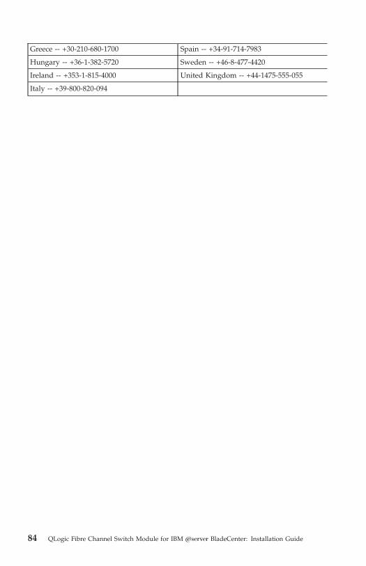
Greece -- +30-210-680-1700 Spain -- +34-91-714-7983
Hungary -- +36-1-382-5720 Sweden -- +46-8-477-4420
Ireland -- +353-1-815-4000 United Kingdom -- +44-1475-555-055
Italy -- +39-800-820-094
84 QLogic Fibre Channel Switch Module for IBM Eserver BladeCenter: Installation Guide
Notices
This information was developed for products and services offered in the U.S.A.
IBM may not offer the products, services, or features discussed in this
document in other countries. Consult your local IBM representative for
information on the products and services currently available in your area. Any
reference to an IBM product, program, or service is not intended to state or
imply that only that IBM product, program, or service may be used. Any
functionally equivalent product, program, or service that does not infringe any
IBM intellectual property right may be used instead. However, it is the user’s
responsibility to evaluate and verify the operation of any non-IBM product,
program, or service.
IBM may have patents or pending patent applications covering subject matter
described in this document. The furnishing of this document does not give you
any license to these patents. You can send license inquiries, in writing, to:
IBM Director of Licensing
IBM Corporation
North Castle Drive
Armonk, NY 10504-1785
U.S.A.
INTERNATIONAL BUSINESS MACHINES CORPORATION PROVIDES THIS
PUBLICATION “AS IS” WITHOUT WARRANTY OF ANY KIND, EITHER
EXPRESS OR IMPLIED, INCLUDING, BUT NOT LIMITED TO, THE IMPLIED
WARRANTIES OF NON-INFRINGEMENT, MERCHANTABILITY OR FITNESS
FOR A PARTICULAR PURPOSE. Some states do not allow disclaimer of
express or implied warranties in certain transactions, therefore, this statement
may not apply to you.
This information could include technical inaccuracies or typographical errors.
Changes are periodically made to the information herein; these changes will be
incorporated in new editions of the publication. IBM may make improvements
and/or changes in the product(s) and/or the program(s) described in this
publication at any time without notice.
Any references in this information to non-IBM Web sites are provided for
convenience only and do not in any manner serve as an endorsement of those
Web sites. The materials at those Web sites are not part of the materials for this
IBM product, and use of those Web sites is at your own risk.
IBM may use or distribute any of the information you supply in any way it
believes appropriate without incurring any obligation to you.
© Copyright IBM Corp. 2005 85

Edition notice
© Copyright International Business Machines Corporation 2005. All rights
reserved.
U.S. Government Users Restricted Rights — Use, duplication, or disclosure
restricted by GSA ADP Schedule Contract with IBM Corp.
Trademarks
The following terms are trademarks of International Business Machines
Corporation in the United States, other countries, or both:
Active Memory Predictive Failure
Analysis
Active PCI PS/2
Active PCI-X ServeRAID
Alert on LAN ServerGuide
BladeCenter ServerProven
C2T Interconnect TechConnect
Chipkill ThinkPad
EtherJet Tivoli
e-business logo Tivoli Enterprise
Eserver Update Connector
FlashCopy Wake on LAN
IBM XA-32
IBM (logo) XA-64
IntelliStation X-Architecture
NetBAY XceL4
Netfinity XpandOnDemand
NetView xSeries
OS/2 WARP
Intel, MMX, and Pentium are trademarks of Intel Corporation in the United
States, other countries, or both.
Microsoft, Windows, and Windows NT are trademarks of Microsoft
Corporation in the United States, other countries, or both.
UNIX is a registered trademark of The Open Group in the United States and
other countries.
86 QLogic Fibre Channel Switch Module for IBM Eserver BladeCenter: Installation Guide
Java and all Java-based trademarks and logos are trademarks or registered
trademarks of Sun Microsystems, Inc. in the United States, other countries, or
both.
Adaptec and HostRAID are trademarks of Adaptec, Inc., in the United States,
other countries, or both.
Linux is a trademark of Linus Torvalds in the United States, other countries, or
both.
Red Hat, the Red Hat “Shadow Man” logo, and all Red Hat-based trademarks
and logos are trademarks or registered trademarks of Red Hat, Inc., in the
United States and other countries.
McDATA, the McDATA logo, SANtegrity, and all McDATA-based trademarks
and logos are trademarks or registered trademarks of McDATA Corporation in
the United States, other countries, or both.
QLogic is a trademark or registered trademark of QLogic Corporation in the
United States, other countries, or both.
Other company, product, or service names may be trademarks or service marks
of others.
Important notes
Processor speeds indicate the internal clock speed of the microprocessor; other
factors also affect application performance.
CD-ROM drive speeds list the variable read rate. Actual speeds vary and are
often less than the maximum possible.
When referring to processor storage, real and virtual storage, or channel
volume, KB stands for approximately 1000 bytes, MB stands for approximately
1 000 000 bytes, and GB stands for approximately 1 000 000 000 bytes.
When referring to hard disk drive capacity or communications volume, MB
stands for 1 000 000 bytes, and GB stands for 1 000 000 000 bytes. Total
user-accessible capacity may vary depending on operating environments.
Maximum internal hard disk drive capacities assume the replacement of any
standard hard disk drives and population of all hard disk drive bays with the
largest currently supported drives available from IBM.
Maximum memory may require replacement of the standard memory with an
optional memory module.
Notices 87

IBM makes no representation or warranties regarding non-IBM products and
services that are ServerProven®, including but not limited to the implied
warranties of merchantability and fitness for a particular purpose. These
products are offered and warranted solely by third parties.
IBM makes no representations or warranties with respect to non-IBM products.
Support (if any) for the non-IBM products is provided by the third party, not
IBM.
Some software may differ from its retail version (if available), and may not
include user manuals or all program functionality.
Product recycling and disposal
This unit contains materials such as circuit boards, cables, electromagnetic
compatibility gaskets, and connectors which may contain lead and
copper/beryllium alloys that require special handling and disposal at end of
life. Before this unit is disposed of, these materials must be removed and
recycled or discarded according to applicable regulations. IBM offers
product-return programs in several countries. Information on product recycling
offerings can be found on IBM’s Internet site at
http://www.ibm.com/ibm/environment/products/prp.shtml.
IBM encourages owners of information technology (IT) equipment to
responsibly recycle their equipment when it is no longer needed. IBM offers a
variety of programs and services to assist equipment owners in recycling their
IT products. Information on product recycling offerings can be found on IBM’s
Internet site at http://www.ibm.com/ibm/environment/products/prp.shtml.
Electronic emission notices
Federal Communications Commission (FCC) statement
Note: This equipment has been tested and found to comply with the limits for
a Class A digital device, pursuant to Part 15 of the FCC Rules. These limits are
designed to provide reasonable protection against harmful interference when
the equipment is operated in a commercial environment. This equipment
generates, uses, and can radiate radio frequency energy and, if not installed
and used in accordance with the instruction manual, may cause harmful
interference to radio communications. Operation of this equipment in a
residential area is likely to cause harmful interference, in which case the user
will be required to correct the interference at his own expense.
Properly shielded and grounded cables and connectors must be used in order
to meet FCC emission limits. IBM is not responsible for any radio or television
interference caused by using other than recommended cables and connectors or
88 QLogic Fibre Channel Switch Module for IBM Eserver BladeCenter: Installation Guide
by unauthorized changes or modifications to this equipment. Unauthorized
changes or modifications could void the user’s authority to operate the
equipment.
This device complies with Part 15 of the FCC Rules. Operation is subject to the
following two conditions: (1) this device may not cause harmful interference,
and (2) this device must accept any interference received, including
interference that may cause undesired operation.
Notices 89

Industry Canada Class A emission compliance statement
This Class A digital apparatus complies with Canadian ICES-003.
Avis de conformité à la réglementation d’Industrie Canada
Cet appareil numérique de la classe A est conforme à la norme NMB-003 du
Canada.
Australia and New Zealand Class A statement
Attention: This is a Class A product. In a domestic environment this product
may cause radio interference in which case the user may be required to take
adequate measures.
United Kingdom telecommunications safety requirement
Notice to Customers
This apparatus is approved under approval number NS/G/1234/J/100003 for
indirect connection to public telecommunication systems in the United
Kingdom.
European Union EMC Directive conformance statement
This product is in conformity with the protection requirements of EU Council
Directive 89/336/EEC on the approximation of the laws of the Member States
relating to electromagnetic compatibility. IBM cannot accept responsibility for
any failure to satisfy the protection requirements resulting from a
nonrecommended modification of the product, including the fitting of non-IBM
option cards.
This product has been tested and found to comply with the limits for Class A
Information Technology Equipment according to CISPR 22/European Standard
EN 55022. The limits for Class A equipment were derived for commercial and
industrial environments to provide reasonable protection against interference
with licensed communication equipment.
Attention: This is a Class A product. In a domestic environment this product
may cause radio interference in which case the user may be required to take
adequate measures.
90 QLogic Fibre Channel Switch Module for IBM Eserver BladeCenter: Installation Guide
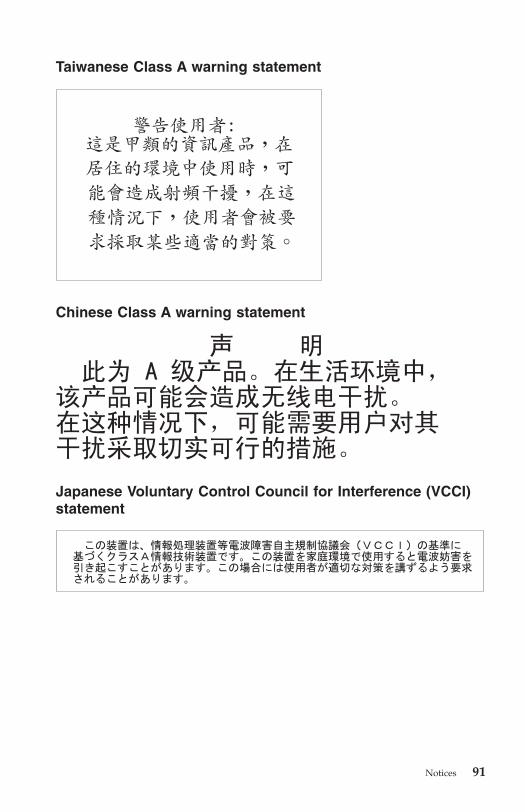
Taiwanese Class A warning statement
Chinese Class A warning statement
Japanese Voluntary Control Council for Interference (VCCI)
statement
Notices 91

92 QLogic Fibre Channel Switch Module for IBM Eserver BladeCenter: Installation Guide

Index
Aacoustic attenuation module option,
removing 19, 21
Active Session from Same Client
window 31
adding optional features 56
advanced features 35
BBladeCenter Management Module Web
interface, using 29
BladeCenter unit 1
blue touch points 11, 14
Ccapabilities, increasing 55
chassis serial number 2, 55
checklistinventory 10
static-sensitive devices 15
command-line interface (CLI) 1
compatible options Web site 14
components, major 11
configuration menus 26
connecting to the switch moduleWeb interface 36
connections to Fibre Channel expansion
cards 13
connectors, electrostatic discharge
(ESD) 15
Ddata window and tabs 50
default fabric view 44, 48
determining the chassis serial
number 2, 55
diagnostic flash patterns of LEDs 27
documentation, related 3, 4, 5
Eencryption key
default 44
error detection feature 8
establishing a Telnet sessioncommand-line window 32
management module 30
establishing a Web-interface sessionmanagement module 36
Web browser 38
exitingSANsurfer 49
expanding the functionality of the switch
module 55
external portscharacteristics 9
Fibre Channel 9
LC-LC fiber-optic cables 20
Ffabric
aggregate bandwidth 9
current fabric view 49
default fabric view 44, 48
latency 9
Management method 10
point-to-point 9
port speed 9
security 7
tree 50
fabric address notification (FAN)
feature 8
faceplate 38, 50
features 7, 8
Fibre Channelexpansion card requirements 13
ports 9, 26
protocols 9
service classes 9
switch fault LED 27, 28
Fibre Channel switch moduleconnections to expansion cards 13
features 7, 8
front panel 25
© Copyright IBM Corp. 2005 93
Fibre Channel switch module (continued)function 13
installation guidelines 14
installing 18
LEDs 26
removing or replacing 21, 22
specifications 9, 10
firmwareinstallation 7
power-on self-test (POST) 20
frame bundling feature 8
functionality, expanding 55
Ggraphic window 50
grounding system 15
Hhandling static-sensitive devices 15
hardware requirements, SANsurfer 42
hot-swap component color 11, 14
II/O module
QLogic 10-port 4 Gb Fibre Channel
switch module 1
QLogic 20-port 4 Gb Fibre Channel
switch module 1
QLogic 6-port Fibre Channel switch
module 1
IBM eServer BladeCenter Type 8677 13
IBM support Web site 4
indicators 26
information panel 25
installationguidelines 14
I/O module 18
illustration 18
procedure 19
requirements 13
SANsurfer 41
installinga switch module 19
optional features 56
options 14
interchangeable terms 1
internal ports 9
Internet protocol (IP) address 30, 35, 36
interswitch link security 7
inventory checklist 10
LLED
! (Fibre Channel switch fault) 27, 28
diagnostic flash patterns 27
front view 26
OK 27
port activity 27, 28
port fault 27, 28
port logged-in 27, 28
license key, Web site 55
Mmajor components of I/O module 11
management moduleconfiguration settings 29, 35
establishing a Telnet session 30
establishing a Web-interface
session 36
Web interface 29, 35
management workstation 29, 35
McDATA SANtegrity Authentication 55
McDATA SANtegrity Binding 55
McDATA Web site for license key 55
meanings of colorson components 11, 14
on LEDs 26, 27
media access control (MAC) address 3
Microsoft Windows 2000installing the SANsurfer 43
uninstalling the SANsurfer 44
Microsoft Windows 2003installing the SANsurfer
application 43
uninstalling the SANsurfer
application 44
Nnetwork management requirements 42,
43
noticesused in this book 6
notices and statements 6
94 QLogic Fibre Channel Switch Module for IBM Eserver BladeCenter: Installation Guide

Oobtaining a license key 55
OK LED 27
online help 49
optional features 8, 55
optionsinstalling 14
Web site 14
orange touch points 11, 14
orientation for installing/removing
switch module 18, 22
Pplug, electrostatic discharge (ESD) 15
port activity LED 27, 28
port fault LED 27, 28
port logged-in LED 27, 28
power-on indicator 27
power-on self-test (POST) 10, 19, 20, 27
Preferences window 48
product data 2
protecting yourself from electrostatic
discharge (ESD) 15
purchasing a software license 55
RRed Hat Linux
installing the SANsurfer
application 45
uninstalling the SANsurfer
application 46
registered state change notification
(RSCN) support feature 7
related documentation 3, 4, 5
removingacoustic attenuation module 19
I/O module 21, 22
Ssafety information
electrostatic discharge (ESD) 15
handling static-sensitive devices 15
introduction vi
multilingual pointer v
Statement 1 vii
Statement 5 ix
SANbrowserconfiguring the switch module 35
SANbrowser (continued)Faceplate window 38
SANsurferchanging password 48
exiting 49
faceplate windows 50
Fibre Channel switch modules 41
installing 41
Load Default Fabric View File
window 44
Microsoft Windows 2000 43
Microsoft Windows 2003 43
network management
requirements 43
online help 49
Preferences window 48
Red Hat Linux 45
setting user preferences 48
starting 47
SUSE LINUX 45
system requirements 42
topology 50
uninstalling on Microsoft Windows
2000 44
uninstalling on Microsoft Windows
2003 44
SANsurfer Switch Managerfirmware installation 7
management methods 9, 10
security feature 7
serial number 2, 55
simple name server implementation 7
small form-factor pluggable (SFP)
modules 6, 9, 20
software features 8, 55
software license requirements 55
software requirements, SANsurfer 42
specifications 7
static electricity 15
static-sensitive devices, handling 15
storage area network (SAN) 2
strap, electrostatic discharge (ESD) 15
support CD 6
SUSE LINUXinstalling the SANsurfer 45
uninstalling the SANsurfer
application 46
switchQLogic 10-port 4 Gb Fibre Channel
switch module 1
QLogic 20-port 4 Gb Fibre Channel
switch module 1
Index 95

switch (continued)QLogic 6-port Fibre Channel switch
module 1
switch moduleQLogic 10-port 4 Gb Fibre Channel
switch module 1
QLogic 20-port 4 Gb Fibre Channel
switch module 1
QLogic 6-port Fibre Channel switch
module 1
system reliability 15
system requirements, SANsurfer 42
TTelnet
configuring the I/O module 29
connecting to the Fibre Channel
switch module 30
interface 29
session, establishingthrough command-line
window 32
through management module 30
toolbar 50
topology 50
touch points 11, 14
Vverifying license installation 56
vertical orientation for installing switch
module 18
WWeb interface
configuring the switch module 35
connecting to the switch module 36
sessionestablishing through management
module 36
establishing through Web
browser 38
using the SANbrowser 35
Web siteBladeCenter documentation 3
IBM support 4
McDATA license key for optional
feature 55
product information 2
Web site (continued)support telephone numbers 55
Web-based network management 41
windowActive Session from Same Client 31
Add a New Fabric 47
faceplate 51
Load Default Fabric View File 44
Preferences 48
SANbrowser Faceplate 38
topology 51
working status indicator 51
worldwide name (WWN) 2
wrist strap, electrostatic discharge
(ESD) 15
96 QLogic Fibre Channel Switch Module for IBM Eserver BladeCenter: Installation Guide


����
Part Number: 59P4386
Printed in USA
(1P) P/N: 59P4386