report · report pre-feasibility study mmakau coal ... the safety classification of the facility...
TRANSCRIPT
Metallurgical Resources Consulting
Centurion Midstream 1692 South Africa T +61 3 8601 3300 82 374 1553 E [email protected]
Report Pre-Feasibility Study Mmakau Coal Pty Ltd
August 2017
Classification
Confidential
Pre-Feasibility Study Mmakau Coal Pty Ltd
Chapter 8: Discard Dump 8-ii
Executive Summary
Chapter 1 Geology
Chapter 2 Mining
Chapter 3 Coal Characterization
Chapter 4 Coal Handling Preparation Plant
Chapter 5 Geotechnical
Chapter 6 Stormwater Management Plan
Chapter 7 Infrastructure
Chapter 8 Discard Disposal Chapter 9 Traffic Study
Chapter 10 Mine Water Balance
Chapter 11 Human Resources
Chapter 12 Capital Costs
Chapter 13 Operating Costs
Chapter 14 Project Implementation Plan
Chapter 15 Risk Assessment
Chapter 16 Economic Evaluation
Chapter 17 Conclusions and Recommendations
Chapter 18 Alternative Options

Pre-Feasibility Study Mmakau Coal Pty Ltd
Chapter 8: Discard Dump 8-iii
Contents
8 Discard Dump ....................................................................................................................................... 8-4 8.1 Introduction ................................................................................................................................. 8-4 8.2 Feasibility of design of discard disposal facility .......................................................................... 8-4
8.2.1 Seepage and Slope Stability Analysis ................................................................... 8-4 8.2.2 Hydrology and Surface Water Management ......................................................... 8-4
8.3 Hazard Classification of Disposal facility ................................................................................... 8-4 8.3.1 Safety Classification .............................................................................................. 8-4 8.3.2 Environmental Classification ................................................................................. 8-5
8.3.2.1 Surface Water ........................................................................................ 8-5 8.3.2.2 Ground Water ......................................................................................... 8-5 8.3.2.3 Land Use ................................................................................................ 8-5 8.3.2.4 Aesthetic Impacts ................................................................................... 8-5 8.3.2.5 Atmospheric Pollution ............................................................................ 8-6 8.3.2.6 General ................................................................................................... 8-6
8.4 Description of works for establishment of the Discard dump ..................................................... 8-6 8.4.1 Site clearance and topsoil stripping ....................................................................... 8-6 8.4.2 Preparation of the discard disposal facility footprint .............................................. 8-7 8.4.3 Liner and underdrainage system ........................................................................... 8-7 8.4.4 Leakage detection system ..................................................................................... 8-7 8.4.5 Surface water containment system ....................................................................... 8-7 8.4.6 Silt trap and pollution control dam ......................................................................... 8-7 8.4.7 Rehabilitation of disturbed areas ........................................................................... 8-7 8.4.8 Construction and rehabilitation materials balance................................................. 8-8
Tables
Table 8-1: Schurvekop Discard Disposal Facility - Safety Classification ....................................................... 8-5
Figures
Figure 8-1: Discard dump layout .................................................................................................................... 8-6
Appendices
No table of figures entries found.
Distribution list
1 e-copy to Mmakau Coal Pty Ltd 1 e-copy to Exxaro Pty Ltd
Pre-Feasibility Study Mmakau Coal Pty Ltd
Chapter 8: Discard Dump 8-4
8 Discard Dump
8.1 Introduction
A summary of the description of work carried out in the feasibility design, the hazard classification and the description of capital works for establishment for the discard disposal facility is presented in the chapter. This should be read in conjunction with applicable drawings and calculations contained in appendices.
8.2 Feasibility of design of discard disposal facility
8.2.1 Seepage and Slope Stability Analysis
Seepage and slope stability analyses of the proposed facility have not yet been carried out due to a lack of representative geotechnical information. Based on the available information and the proposed configuration of the discard disposal facility, it is not expected that any problems will be experienced with its structural integrity. The nature of the discards, which will to all intents and purposes be deposited dry, and the absence of any water inputs to the facility other than infiltration associated with rainfall, make it likely that conditions within the dump will remain unsaturated. This will retard the migration of infiltration through the dump and make it unlikely that a phreatic surface would develop within the discards. It is therefore also unlikely that there would be any seepage to the foundation materials underlying the discard dump.
8.2.2 Hydrology and Surface Water Management
The site stormwater management plan dictates that run-off from the discard disposal site will be collected in the cut of channel which surround the discard area. The channels drain to Pollution Control Dam A as per the requirements of the regulation 704 which states that polluted water is not allowed to be discharged into the environment for storms exceeding the 50 year recurrence interval.
The Schurvekop stormwater management plan is discussed in detail in Chapter 6. Calculation have been carried for the site to estimate run-off volumes and maximum likely discharge rates for a range of recurrence intervals and event durations.
The site is divided into two catchment areas with run-off of volumes of 32 Mℓ /annum and 54 Mℓ /annum respectively in a 1:50 year flood event. PCD A has been designed to contain 86.5 Mℓ /annum. The pollution control dam has sufficient storage capacity to accept and retain the expected volumes of surface water runoff from the discard disposal facility.
8.3 Hazard Classification of Disposal facility
8.3.1 Safety Classification
The safety classification of the facility has been carried out in accordance with the requirements of SABS 0286:1998: Code of Practice for Mine Residue. The safety classification system serves to provide a consistent means of differentiating between high, medium and low hazard deposits on the basis of their potential to cause harm to life or property. The classification system furthermore provides a basis for the implementation of safety management practices for specified stages of the life cycle of mine residue disposal facilities. The code prescribes the aims, principles and minimum requirements that apply to the classification procedure and the classification in turn gives rise to minimum requirements for investigation, design, construction, operation and decommissioning.
The approximate area that may be affected by a flow slide originating from a residue deposit is usually determined based on the guideline values from the Code of Practice and the topography of the area. Based on the nature of the discards however it is not expected that the facility would ever be subject to a flow slide and the associated release of discards. It is not expected therefore that the zone of influence would extend beyond the perimeter road of the facility. Based on the zone of influence as defined and the criteria specified in the code, the discard disposal facility has been classified as a low hazard facility.
Pre-Feasibility Study Mmakau Coal Pty Ltd
Chapter 8: Discard Dump 8-5
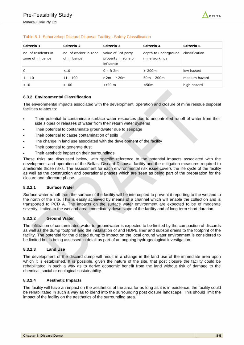
Table 8-1: Schurvekop Discard Disposal Facility - Safety Classification
Criteria 1 Criteria 2 Criteria 3 Criteria 4 Criteria 5
no. of residents in
zone of influence
no. of worker in zone
of influence
value of 3rd party
property in zone of
influence
depth to underground
mine workings
classification
0 <10 0 – R 2m > 200m low hazard
1 – 10 11 - 100 r 2m – r 20m 50m – 200m medium hazard
>10 >100 >r20 m <50m high hazard
8.3.2 Environmental Classification
The environmental impacts associated with the development, operation and closure of mine residue disposal facilities relates to:
Their potential to contaminate surface water resources due to uncontrolled runoff of water from their side slopes or releases of water from their return water systems
Their potential to contaminate groundwater due to seepage
Their potential to cause contamination of soils
The change in land use associated with the development of the facility
Their potential to generate dust
Their aesthetic impact on their surroundings
These risks are discussed below, with specific reference to the potential impacts associated with the development and operation of the Belfast Discard Disposal facility and the mitigation measures required to ameliorate those risks. The assessment for each environmental risk issue covers the life cycle of the facility as well as the construction and operational phases which are seen as being part of the preparation for the closure and aftercare phase.
8.3.2.1 Surface Water
Surface water runoff from the surface of the facility will be intercepted to prevent it reporting to the wetland to the north of the site. This is easily achieved by means of a channel which will enable the collection and is transported to PCD A. The impacts on the surface water environment are expected to be of moderate severity, limited to the wetland area immediately down slope of the facility and of long term short duration.
8.3.2.2 Ground Water
The infiltration of contaminated water to groundwater is expected to be limited by the compaction of discards as well as the dump footprint and the installation of and HDPE liner and subsoil drains to the footprint of the facility. The potential for the discard dump to impact on the local ground water environment is considered to be limited but is being assessed in detail as part of an ongoing hydrogeological investigation.
8.3.2.3 Land Use
The development of the discard dump will result in a change in the land use of the immediate area upon which it is established. It is possible, given the nature of the site, that post closure the facility could be rehabilitated in such a way as to derive economic benefit from the land without risk of damage to the chemical, social or ecological sustainability.
8.3.2.4 Aesthetic Impacts
The facility will have an impact on the aesthetics of the area for as long as it is in existence. the facility could be rehabilitated in such a way as to blend into the surrounding post closure landscape. This should limit the impact of the facility on the aesthetics of the surrounding area.
Pre-Feasibility Study Mmakau Coal Pty Ltd
Chapter 8: Discard Dump 8-6
8.3.2.5 Atmospheric Pollution
The facility will, as with all discard disposal sites, have the potential to generate windblown dust. The compaction and ongoing rehabilitation of the facility is however likely to mitigate the effects of wind on the facility.
8.3.2.6 General
Based on the assessment as outlined above it is concluded that the facility will have the potential to impact on the surrounding environment and care has been taken to minimise those impacts, particularly on the surface and ground water environments.
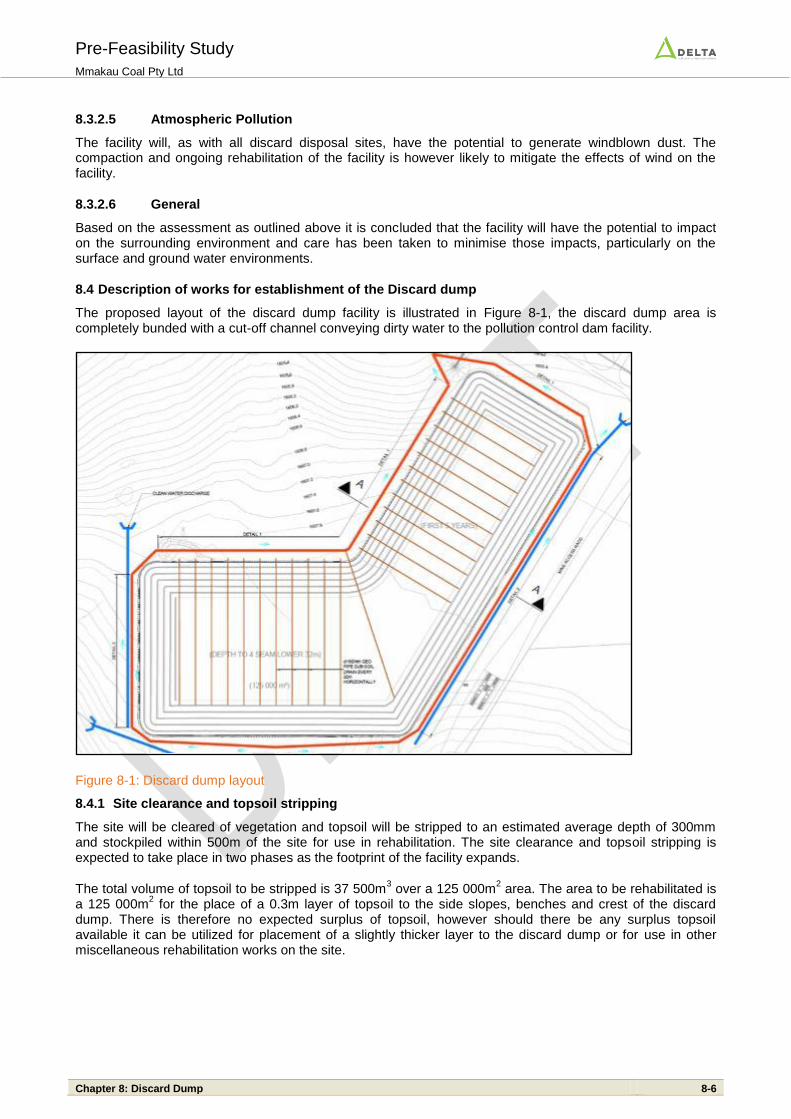
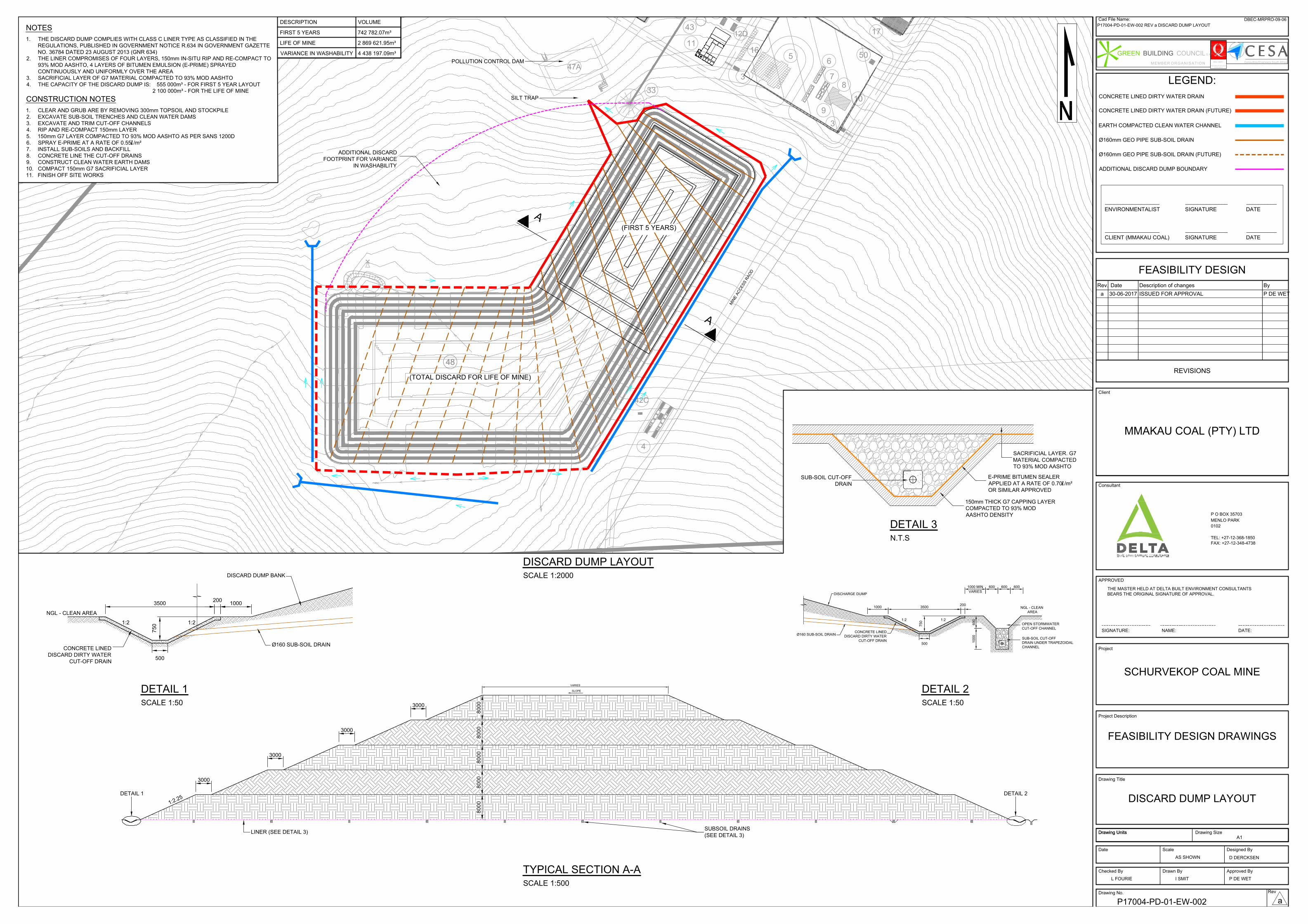
8.4 Description of works for establishment of the Discard dump
The proposed layout of the discard dump facility is illustrated in Figure 8-1, the discard dump area is completely bunded with a cut-off channel conveying dirty water to the pollution control dam facility.
Figure 8-1: Discard dump layout
8.4.1 Site clearance and topsoil stripping
The site will be cleared of vegetation and topsoil will be stripped to an estimated average depth of 300mm and stockpiled within 500m of the site for use in rehabilitation. The site clearance and topsoil stripping is expected to take place in two phases as the footprint of the facility expands.
The total volume of topsoil to be stripped is 37 500m3 over a 125 000m
2 area. The area to be rehabilitated is
a 125 000m2 for the place of a 0.3m layer of topsoil to the side slopes, benches and crest of the discard
dump. There is therefore no expected surplus of topsoil, however should there be any surplus topsoil available it can be utilized for placement of a slightly thicker layer to the discard dump or for use in other miscellaneous rehabilitation works on the site.
Pre-Feasibility Study Mmakau Coal Pty Ltd
Chapter 8: Discard Dump 8-7
8.4.2 Preparation of the discard disposal facility footprint
The preparation of the discard disposal facility is expected to comprise the phased preparation of the footprint for the deposition of discards by ripping and re-compacting the in-situ soils remaining after stripping of the topsoil to a depth of at least 300mm. The preparation of the footprint will include also the construction of a nominal toe wall to the perimeter of the area on which discards are to be placed.
8.4.3 Liner and underdrainage system
A U24 bidim or approved equivalent will be installed to the footprint of the discard dump in phases as the development of the facility proceeds. The liner would be placed on top of a protective layer of geosynthetic clay liner placed onto a 50mm sand capping and 150mm thick prepared in-situ surface, compacted to 90% MOD AASHTO density. The liner would then be covered with 150mm thick G7 capping layer, compacted to 93% MOD AASHTO. This layer will be sealed with E-prime bitumen sealer applied at a rate of 0.7 ℓ/m
2.
Discards will be placed and compacted in 300mm layers from the edge of the lined area and working inwards so as to minimise the chances of damaging the liner. A series of under drains will be installed to the footprint of the discard disposal facility. These drains will comprise shallow trenches into which slotted drainage pipes and filter stone are placed to form the drains. The drains will be wrapped in geofabric and will discharge to the channels surrounding the facility. The drain outlets will be equipped with 45º bends to ensure that ingress of air into the pipe, and to the foundation of the discards, is prevented by the presence of drainage water. At closure the pipe outlets m sealed and fitted with end caps to prevent the ingress of oxygen to the drains.
8.4.4 Leakage detection system
A series of leakage detection drains has been allowed for to assist in monitoring the performance of the liner. The drains will be located so as to intercept potential seepage flows and will comprise slotted drainage pipes within a crushed drain stone and surrounding geofabric. The leakage detection pipes will discharge to the solution trench and will be clearly marked so as to distinguish them from the seepage underdrainage collection pipes.
8.4.5 Surface water containment system
The system proposed for the containment of surface water runoff from the discard disposal facility will comprise:
A network of lined channels intended to collect surface runoff from the side slopes of the discard facility to the pollution control dam north east of the discard dump.
A series of sub-surface drains is located every 20m horizontally throughout the discard dump and 4m vertically.
A concrete lined drain into which seepage water from the sub-surface drainage collects. The channel will carry all such water to the pollution control dam located at to the north east of the discard disposal facility. The solution trench has been sized to facilitate access by small earthmoving equipment to facilitate cleaning of accumulated silt as required.
In addition to the collection of potentially contaminated water from the facility the system described above is intended to facilitate the control of material eroded from the dump and will also have the effect of retarding the flow of runoff from the facility, thereby reducing the peak flow and storm water containment requirements.
8.4.6 Silt trap and pollution control dam
Potentially contaminated surface water runoff and seepage flows will report, through the concrete lined solution channel, to a silt trap and pollution control dam. The facility is not intended to store all runoff from the discard disposal facility but is intended to allow for the settlement of solids remaining in the water flows and to attenuate the flow of runoff to discharge onto the natural ground.
8.4.7 Rehabilitation of disturbed areas
Areas surrounding the discard disposal facility disturbed during the construction process will be rehabilitated as part of the site dis-establishment by the earthworks and civils contractor. The faces of the toe walls and cross walls, surface water diversion trench and berm, and silt trap walls will be covered with a layer of topsoil and seeded with a mixture of indigenous grass seeds.
Pre-Feasibility Study Mmakau Coal Pty Ltd
Chapter 8: Discard Dump 8-8
8.4.8 Construction and rehabilitation materials balance
The construction material of the discard dump will comprise material from the mine pit. The topsoil to be utilized for rehabilitation will be the total quantity stripped from and stockpiled from the site, it is not anticipated that any additional topsoil will be required. A complete balance calculation of the material can it this point not be determined yet.
16
17
4
33
43
48
50
47A
8
9
10
11
5
6
73
3
3
LOCKERS
WC
WHB
SINK
TOILET
GATE HOUSE
LOCKERS
WC
WHB
SINK
TOILET
GATE HOUSE
LOCK
ERS
WC
WHB
SINK
TOILE
T
GA
TE
H
OU
SE
LOCKERS
WC
WHB
SIN
K
TOILET
GATE HOUSE
SINK
TOILET
WAITING AREA
KITCHEN COUNTER
G
E
N
T
S
L
A
D
IE
S
SINK
42C
12D
48
(TOTAL DISCARD FOR LIFE OF MINE)
(FIRST 5 YEARS)
POLLUTION CONTROL DAM
SILT TRAP
(TOTAL DISCARD FOR LIFE OF MINE)
(FIRST 5 YEARS)
A
A
M
I
N
E
A
C
C
E
S
S
R
A
O
D
ADDITIONAL DISCARD
FOOTPRINT FOR VARIANCE
IN WASHABILITY
LINER (SEE DETAIL 3)
DETAIL 2
SUBSOIL DRAINS
(SEE DETAIL 3)
SLOPE
VARIES
DETAIL 1
3000
1
:
2
.
2
5
3000
3000
3000
8000
8000
8000
8000
8000
75
0
NGL - CLEAN AREA
DISCARD DUMP BANK
1000
200
3500
500
1:2 1:2
CONCRETE LINED
DISCARD DIRTY WATER
CUT-OFF DRAIN
Ø160 SUB-SOIL DRAIN
1000
1000 MIN
VARIES
600 600 600
600
10
00
NGL - CLEAN
AREA
DISCHARGE DUMP
SUB-SOIL CUT-OFF
DRAIN UNDER TRAPEZOIDAL
CHANNEL
OPEN STORMWATER
CUT-OFF CHANNEL
CONCRETE LINED
DISCARD DIRTY WATER
CUT-OFF DRAIN
750
200
3500
500
1:2 1:2
Ø160 SUB-SOIL DRAIN
E-PRIME BITUMEN SEALER
APPLIED AT A RATE OF 0.70 /m²
OR SIMILAR APPROVED
150mm THICK G7 CAPPING LAYER
COMPACTED TO 93% MOD
AASHTO DENSITY
SUB-SOIL CUT-OFF
DRAIN
SACRIFICIAL LAYER. G7
MATERIAL COMPACTED
TO 93% MOD AASHTO
ISO 9001
Date Scale Designed By
Checked By Approved ByDrawn By
Drawing No.
LEGEND:
REVISIONS
APPROVED
SIGNATURE: DATE:NAME:
Project
Drawing Title
Client
Consultant
THE MASTER HELD AT DELTA BUILT ENVIRONMENT CONSULTANTS
BEARS THE ORIGINAL SIGNATURE OF APPROVAL.
Rev. Date Description of changes By
Project Description
Rev
Drawing UnitsDrawing Units
P O BOX 35703
MENLO PARK
TEL: +27-12-368-1850
FAX: +27-12-348-4738
0102
Consulting Engineers South Africa
International Standards
Certifications
M E M B E R O R G A N I S A T I O N
GREEN BUILDING COUNCIL S A
Cad File Name:DBEC-MRPRO-09-06
Drawing Size
A1
P17004-PD-01-EW-002 REV a DISCARD DUMP LAYOUT
FEASIBILITY DESIGN
a 30-06-2017 ISSUED FOR APPROVAL P DE WET
SCHURVEKOP COAL MINE
FEASIBILITY DESIGN DRAWINGS
DISCARD DUMP LAYOUT
AS SHOWND DERCKSEN
L FOURIE I SMIT P DE WET
P17004-PD-01-EW-002
a
SCALE 1:2000
DISCARD DUMP LAYOUT
SCALE 1:500
TYPICAL SECTION A-A
SCALE 1:50
DETAIL 2
CONCRETE LINED DIRTY WATER DRAIN
EARTH COMPACTED CLEAN WATER CHANNEL
Ø160mm GEO PIPE SUB-SOIL DRAIN
ADDITIONAL DISCARD DUMP BOUNDARY
ENVIRONMENTALIST SIGNATURE DATE
__________________ ______________ __________
CLIENT (MMAKAU COAL) SIGNATURE DATE
__________________ ______________ __________
N.T.S
DETAIL 3
Ø160mm GEO PIPE SUB-SOIL DRAIN (FUTURE)
SCALE 1:50
DETAIL 1
CONCRETE LINED DIRTY WATER DRAIN (FUTURE)
NOTES
1. THE DISCARD DUMP COMPLIES WITH CLASS C LINER TYPE AS CLASSIFIED IN THE
REGULATIONS, PUBLISHED IN GOVERNMENT NOTICE R.634 IN GOVERNMENT GAZETTE
NO. 36784 DATED 23 AUGUST 2013 (GNR 634)
2. THE LINER COMPROMISES OF FOUR LAYERS, 150mm IN-SITU RIP AND RE-COMPACT TO
93% MOD AASHTO, 4 LAYERS OF BITUMEN EMULSION (E-PRIME) SPRAYED
CONTINUOUSLY AND UNIFORMLY OVER THE AREA
3. SACRIFICIAL LAYER OF G7 MATERIAL COMPACTED TO 93% MOD AASHTO
4. THE CAPACITY OF THE DISCARD DUMP IS: 555 000m³ - FOR FIRST 5 YEAR LAYOUT
2 100 000m³ - FOR THE LIFE OF MINE
MMAKAU COAL (PTY) LTD
CONSTRUCTION NOTES
1. CLEAR AND GRUB ARE BY REMOVING 300mm TOPSOIL AND STOCKPILE
2. EXCAVATE SUB-SOIL TRENCHES AND CLEAN WATER DAMS
3. EXCAVATE AND TRIM CUT-OFF CHANNELS
4. RIP AND RE-COMPACT 150mm LAYER
5. 150mm G7 LAYER COMPACTED TO 93% MOD AASHTO AS PER SANS 1200D
6. SPRAY E-PRIME AT A RATE OF 0.55 /m²
7. INSTALL SUB-SOILS AND BACKFILL
8. CONCRETE LINE THE CUT-OFF DRAINS
9. CONSTRUCT CLEAN WATER EARTH DAMS
10. COMPACT 150mm G7 SACRIFICIAL LAYER
11. FINISH OFF SITE WORKS
DESCRIPTION VOLUME
FIRST 5 YEARS 742 782.07m³
LIFE OF MINE 2 869 621.95m³
VARIANCE IN WASHABILITY 4 438 197.09m³