© sunit oy 2006. - kotisivukone · this manual gives you the guidance of sunit c on-board pc. ......
TRANSCRIPT


2
© Sunit Oy 2006. v.05102009

1. Foreword Reference books and further info .........………………………………….... 2. Identification data ...............................…………………………………... 3. Hardware configuration Configuration of Sunit c ......................………………………………….... Central Processing Unit (CPU) .............…………………………………... Front side of CPU ..............................…………………………………... Installing the SIMM GSM/GPRS card …………………………………. Resetting the computer ………………………………………………….. Rear side of CPU ...............................…………………………………... Display .................................................…………………………………... Buttons & indicators .........................…………………………………... Keyboard and mouse ...........................…………………………………... Typing with the keyboard .................…………………………………... Using the mouse ...............................………………………………….... 4. Maintenance Precautions and protection ....................…………………………………... Cleaning ................................................…………………………………... Software maintenance ...........................…………………………………... 5. Installation CPU installation ....................................…………………………………... Antenna mounting ................................………………………………….... GPS antenna outdoor mounting .........…………………………………... Display Mounting .................................…………………………………... Keyboard and mouse ..........................……………………………………. Cable installation …………………………………………………………. Connecting the cables ...........................…………………………………... Wiring diagram, Digital I/O ………………………………………………. 6. Installation tests Power cable test ....................................………………………………….... Antenna tests .........................................…………………………………... Printer test .............................................…………………………………... Phone test ..............................................…………………………………... Data transfer and GPS test ....................…………………………………... 7. Using the computer Start-up and shut-down .........................…………………………………... Display adjustments ..............................…………………………………... 8. Start-up signals CPU signals ..........................................………………………………….... 9. Specifications Connector specifications .......................…………………………………... Technical specifications .......................………………………………….... 10. Troubleshooting ..................................…………………………………... Appendix A: Sunit Telematics Quick start …..........................………….... Appendix B: Elo touchscreen calibration …………………………………. Appendix C: Sunit touch screen calibration ………………………………. Declaration of Conformity ………………………………………………....
3
4 5 5 5 6 6 6 7 8 8 9 9 9 10 10 10 10 11 11 11 11 11 12 13 14 14 14 14 15 16 17 17 18 19 21 22 26 27 28

FOREWORD This manual gives You the guidance of Sunit c On-board PC. Familiarize to this manual carefully before taking the computer in use. Trade marks and copyrights This manual includes information, which is copyright protected. Copying of this manual or parts of it without permission of the author is forbidden. Sunit Oy develops products continually, therefore we reserve right to make changes to the products described in this manual and it’s instructions without the prior notice. Windows, MS-DOS and Microsoft are Microsoft Corporation’s registered trade marks. Pentium is In-tel Corporation’s registered trade mark. Compatibility The Sunit c computer is compatible with MS-DOS, Windows9x, Windows NT, Windows2000, Win-dows XP or Linux Red Hat 7,0 operating system. Installation and service Only authorized service is allowed to install, repair or open the device. Unauthorized repair or open-ing of the device may cause faulty operation and revoke the warranty. Incorrect wiring may disturb insufficiently protected electronic systems. For further information, please contact [email protected] Connecting of the peripherals The compatibility of the peripheral devices shall be ensured from the manufacturer or reseller of the device. Insufficiently EMC and EMI protected peripherals may disturb electronic components of the vehicle.
The service of the vehicle When welding the vehicle, the Power supply connector (CON16) and all grounded cables must be disconnected before the welding work. Traffic safety Unnecessary use of the On-board computer may endanger traffic safety. It’s recommended to stop the vehicle for using the computer by driver. To avoid accidents keep all peripherals (e.g. keyboard) in store pockets. 1.1 Further information In addition of this document, You can find more information from:
4
Equipment: Support: internet-address
• Sunit c [email protected] www.sunit.fi • GPS receiver Protocol specification www.orcam-gps.com • GSM/GPRS AT commands and settings www.siemens.com/wm • Operating system Windows www.microsoft.com
Become acquainted with the folder C:\Sunit\Support. You will among others find from there device drivers, Service Packs, user guides, warranty clause and utility programs.

5
CPU identification data finds from the frame of the unit: - CPU model and type - BIOS version - production batch - manufacturing year and week - serial number - version of telematic board - CE marking* - recycling mark** Identification data finds from the back cover of the display - manufacturing year and week - display model - serial number - setup code - CE marking* - recycling mark** * CE Marking on a product is a manufacturer's declaration that the product complies with the essential requirements of the relevant European health, safety and environmental protection legislations. ** This symbol means that electrical and electronic equipment, at their end-of-life, should be disposed of separately from your household waste. SUNIT products are manufactured with high quality materials and components which can be recycled and reused. Please dispose of this equipment at waste collection or recycling centre. Please help us to conserve the environment we live in! Data is important for service, so don’t remove it! 3. HARDWARE CONFIGURATION 3.1 Configuration of Sunit d Sunit d On-board computer comprises of: Central Processor Unit, Display Unit, Keyboard, Mouse, Display cable, BUS-cable. Power Supply cable and GPS/GPRS antenna. If supply voltage is higher than +12V, the voltage inverter is required. Depending on the application requirements, configuration can include also integrated GSM/GPRS phone, 802.11b/g WLAN adapter, TV/radio receiver and CAN-interface. 3.2 Central Processing Unit The CPU of the Sunit d On-board computer is PC-based vehicle computer with GPS and LAN fea-ture. It can be equipped with GSM/GPRS phone, TV/radio receiver, CAN interface, multimedia fea-ture, internal PCI-104 board and many other peripherals as e.g. security camera.
2. IDENTIFICATION DATA

6
3.2.1 Front side of CPU The front side of CPU contains:
1. On/off button. Notice that this button is not required in daily use. The unit can be connected on the vehicle’s ignition, which enables the Autostart feature for the computer. The computer shall be switched of by operating system’s shutdown feature. If the computer is switched of using on/off button (press at least 5 sec.), you may loose all unsaved data.
2. CD/DVD drive. For option only.
3. USB connector supports Plug-and-Play feature (as USB keyboard or memory stick). It’s a standard USB with active PWR-connector of +5V.
3.2.2 Installing the SIM GSM/GPRS card The Sunit c computer is implemented by integrated SIMM slot for GSM/GPRS phone. To install the SIM card: 1. Open 2 screws located in front cover and remove cover 2. Release the SIM slot out 3. Install the SIM card 4. Push the slot into the unit 5. Replace the front cover NOTE! Disable PIN code query of the SIM card using hand held GSM phone before installing the SIM card. 3.2.3 Resetting the computer In some exceptional cases the computer may have to be turned off otherwise than an operating system’s Shut down command. In that case the computer should be turned off by pressing on/off button for about 4 seconds. When the computer has shut down, reset the telematics card by pressing the reset button through the hole in the front panel by using a thin needle, paper clip etc. To solve telecommunications problems or location problems the telematics card may have to be reset. In that case shut down the computer from operating system and after that reset the computer.
2
3
RESET button
1
Reset

7
3.2.4 The rear of the CPU 1. BUS connector (RS232, PS/2 mouse, USB) 2. Audio I/O connector 3. GSM/GPRS antenna 4. GPS antenna 5. Power & vehicle I/O 6. Display For specifications of connectors, see page 25 “Connector specifications” 3.3 Display The display is equipped with the Touch Screen feature, internal heating element, error and auto-brightness controls, and loudspeaker. Display sizes are 6.3”, 8.4”, 10.4” and 12.1”. NOTE! Never connect or disconnect the display cable when the unit is running!

3.3.1 Display button & indicators The three indicator leds shows the status of computer: 1. Green continuous: Computer on Green blinking: Computer is starting. 2. Yellow continuous: Preheating mode Yellow blinking (1 sec./1 sec.): CPU only heating mode Yellow blinking (0,2 sec./2 sec.): Display only heating mode 3. Red continuous: Display backlight switched off. 4. Light sensor for automatic brightness adjustment. The lowest level of autobrightness can be ad- justed by the manual adjustment knob (8). 5. Connector for additional keyboard (e.g. Sunit AKU mini keyboard). 6. Connector for display cable. 7. Computer on/off and display on/off. Short press: - if computer is on, display backlight on/off - if computer is off, starts the unit Long press: - if pressed more than 5 seconds, shuts the unit down. NOTE! Required only in exception, refer
to chapter 3.2.1, “On/off button”. 8. The manual adjustment knob of the display’s low-level brightness.
8
1 2 3 4 8 7
5 6

3.4 Keyboard and mouse The keyboard is standard mini-PC/AT USB keyboard. The mouse is either integrated with keyboard or separate PS/2 mouse connected with BUS cable
3.4.1 Typing with the keyboard The instructions of the keys is indicated with square brackets [], e.g. - browsing the document, press [PgUp] or [PgDn] - for CAPITAL LETTERS, press [Shift] and letter simultaneously - for constant writing with capital letters, press [Caps Lock] once, for release press again - [Ctrl], [Alt] and [AltGr] -keys are special keys which are used in combination with other keys, e.g. € (euro) - press [AltGr] and “e” @ (at) - press [AltGr] and “2” For further information about the use of Windows keys and shortcuts, refer the Windows User Guide delivered with the computer. 3.4.2 Using the mouse The mouse is a plane guide mouse and it doesn’t contain any mechanical parts. The mouse is con-nected to the PS/2 port through the BUS cable and the mouse’s own device driver have been in-stalled already at the configuration stage of the computer. The pointer on the display will move when finger is moved on the surface (1) of the control plane. The left button of the mouse (2) functions as the choice button. By clicking the target with the right button (3), either the function menu or the prop-erties of the target is obtained.
9
3 2
1

4. MAINTENANCE 4.1 Precautions and protection Do not scratch or press the cover of the device with sharp objects. You must not touch to the display element with a sharp object. Do not fasten any accessories to the cover of the display or of the cen-tral unit To protect the electronics of the device, the covers must be always kept closed. The device contains an internal heat management systems which controls the fan, so do not set any objects on or over the central unit, which may prevent the ventilation of the device. If any failure occurs, please contact the service. 4.2 Cleaning - clean the filter of the CPU regularly - keep the display and covers clean from dust, oil or other chemicals - clean the device by using a weak detergent - always use a soft towel for cleaning Alkaline or other solvent, alcohol and other similar chemicals must not be used! 4.3 Software maintenance The computer runs with Microsoft Windows or Linux operating system. Particularly Windows operat-ing system is vulnerable for worms, viruses and attacks against known security holes. It’s essential to keep your computer up-to-date with proper virus protection application, e.g. Norton Anti-Virus or simi-lar, and use Windows update -feature regularly. Also using software firewall is very recommended, considering that there are many of them available freely from e.g. internet and Windows XP has this feature build-in. 5. INSTALLATION General The installation of the unit has to be performed systematically. Recommended installation order is: - antennas (GPS, GPRS) and their cables - cables of supplementary devices - attaching cables to the vehicle - testing the cables - installation of the keyboard - mounting of the central unit - mounting of the display - connecting the cables to the central unit - communication test (GPS, GPRS etc.) - peripheral test (printer etc.) Note! The voltage of the vehicle must be disconnected during installation. 5.1 CPU mounting - choose location, which is in accordance with the purpose - ensure sufficient ventilation for the unit, do not use any closed box or such - mount the CPU in the vehicle
10

11
In the roof mounting flip the cover of the CPU.
5.2 Mounting antennas The GPS and GPRS -antenna works on highest performance when installed outside of the cabin. It’s recommended to leave 400 mm free space between similar antennas and GPS-antenna has at least 135° free signal space, both horizontally and vertically. If the vehicle has very oblique window, GPS-antenna can be mounted inside of the cabin. Follow the installation manual which comes with the antenna! Note! Ensure that window is not coated with any material that could block signal. 5.2.1 Outdoor mounting - see the instruction delivered with antenna 5.3 Display mounting When mounting the display, the traffic safety has to be taken into consideration. Do not mount dis-play so that will prevent visibility or disturb the control of the vehicle. Pay attention to passengers’ and driver’s safety to avoid unnecessary injuries in case of possible accident. 5.4 Keyboard and mouse installation Choose the location for the keyboard and mouse, so that it will be easy to reach them. The USB con-nector is recommended to be placed close to USB supplementary devices. Always consider the traffic safety!
5.5 Cable installation - make sure that the location of cables doesn’t cause any breaks or wear. - install cables under the upholstery - make sure that cables doesn’t rub against sharp objects - don’t make sharp angles - don’t twine cables

12
5.6 Connections of the cables

13
Wiring diagram; Digital I/O

5.6.1 Functions of the vehicle cable Functions of the vehicle cable can be set according to user’s demand. Standard settings and wires are described in connector layout on page 19. - CON16/pin18 (Heat Start), if connected with wake-up signal (e.g. Webasto) to 12V/24V, the unit will start preheating, otherwise when ignition key is turned on (selectable in Sunit Telematics). The most of the features of the vehicle cable are adjustable in Sunit Telematics application, refer to Appendix A - Sunit Telematics instructions. 6. INSTALLATION TESTS 6.1 Power cable test Before connecting cables to the CPU they have to be tested. With this test one can ensure that de-vices wouldn’t get damaged when current will be connected. Use the multimeter for testing - grounding (GND): Test to the body of the vehicle with “beep” -function - constant power supply (PWR-IN): measure the voltage 12V when the ignition key is off - start of the pre-heating (Heat Start/DI5): Measure that voltage is 12V or 24V - current of the ignition lock (Ignition): Measure that voltage is 12V or 24V when the ignition key is on If these tests are passed successfully, cables are installed correctly. 6.2 Antenna tests If the GPS or phone doesn’t get the connection after installation, the antennas shall to be measured. Loosen the power connector (PWR) and check that the cables of antennas are properly in their own connectors in the CPU. Check that the cables are undamaged. GPS antenna Measure that the resistance between the signal and ground is not in short circuit (not 0Ω) or cut (not ∞Ώ). Phone antenna Measure that the resistance between the signal and ground is ∞Ώ i.e. infinitive. 6.3 Printer test If the printer is connected, test it from operating system’s printer setup. 6.4 Phone test The Sunit c On-board PC includes the internal GSM/GPRS-phone as option. The testing of the phone is performed preferably with which is normally used in the assignments. If there isn’t such, test can be performed with e.g. Windows HyperTerminal.
14

6.5 Data transfer and GPS test The Data transfer test can be performed with Windows HyperTerminal. Note! The GPS is connected to COM3 and the phone to COM4. Write e.g. “GPS3”, click “OK”. Write phone number, select port (COM3 for GPS, COM4 for phone). - bit rate = 4800 or 9600 - data bits = 8 - parity = none - stop bits = 0 Click “OK”
15
Stop display’s rolling by hitting [Enter].
Field | 1 | 2, 3 | 4, 5 | 6 | 7 | 8 | 9, 10 | 11, 12 | $GPGGA | 070559| 6413.1928,N| 02747.0007,E| 2 | 08 | 1.59 | 160.6,M |
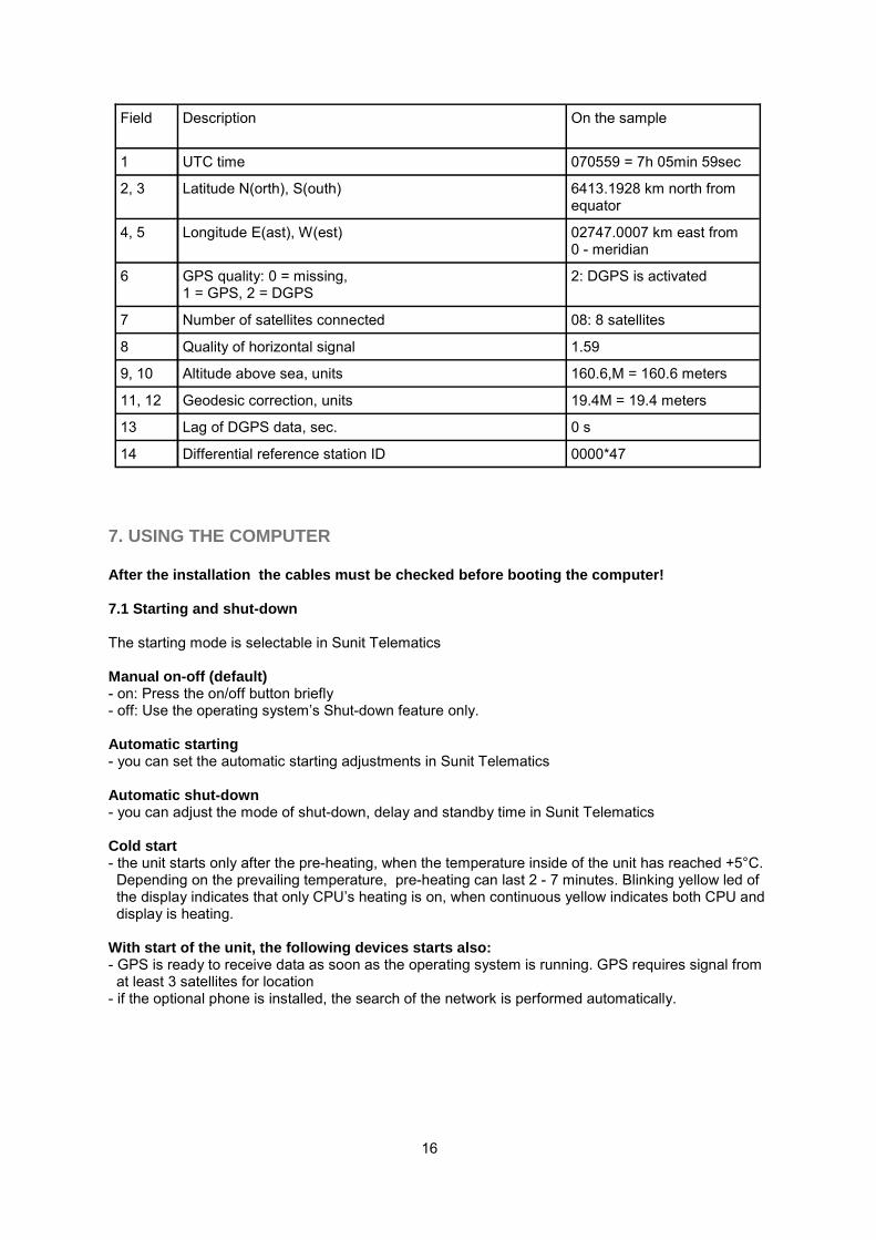
For explanations look the table on the following page.
16
Field Description
On the sample
1 UTC time 070559 = 7h 05min 59sec
2, 3 Latitude N(orth), S(outh) 6413.1928 km north from equator
4, 5 Longitude E(ast), W(est) 02747.0007 km east from 0 - meridian
6 GPS quality: 0 = missing, 1 = GPS, 2 = DGPS
2: DGPS is activated
7 Number of satellites connected 08: 8 satellites
8 Quality of horizontal signal 1.59
9, 10 Altitude above sea, units 160.6,M = 160.6 meters
11, 12 Geodesic correction, units 19.4M = 19.4 meters
13 Lag of DGPS data, sec. 0 s
14 0000*47 Differential reference station ID
7. USING THE COMPUTER After the installation the cables must be checked before booting the computer! 7.1 Starting and shut-down The starting mode is selectable in Sunit Telematics Manual on-off (default) - on: Press the on/off button briefly - off: Use the operating system’s Shut-down feature only. Automatic starting - you can set the automatic starting adjustments in Sunit Telematics Automatic shut-down - you can adjust the mode of shut-down, delay and standby time in Sunit Telematics Cold start - the unit starts only after the pre-heating, when the temperature inside of the unit has reached +5°C. Depending on the prevailing temperature, pre-heating can last 2 - 7 minutes. Blinking yellow led of the display indicates that only CPU’s heating is on, when continuous yellow indicates both CPU and display is heating. With start of the unit, the following devices starts also: - GPS is ready to receive data as soon as the operating system is running. GPS requires signal from at least 3 satellites for location - if the optional phone is installed, the search of the network is performed automatically.

17
7.2 Display adjustments The display is equipped with automatic adjustment of the backlight, therefore manual adjustment of the brightness is not recommended except in the dark - adjust the minimum brightness by following instructions given in page 8 - manual adjusting effects only in twilight or in the dark 8. START-UP SIGNALS The PC has internal control system which controls the status of the device. If the device states a faulty function during start-up, it indicates it with audible signal; one long and one or more short “beeps” according to the following list. 8.1 CPU signals If in combination with the signal and the continuous green light of the display, signal means:
Error signals can be disabled by pressing the main switch.
(Long) + 1
GPS antenna not connected
Check the antenna connector and cable
(Long) + 2
Short circuit in GPS antenna
Check the antenna connector and cable
(Long) + 3
GPS power fault
Check the antenna connector and cable
(Long) + 4
Keyboard power fault
Check connector and cable
(Long) + 5
USB power fault
Check cable
(Long) + 6
GSM power fault
Check connector and cable
(Long) + 7
Fan doesn’t work
Contact the service
(Long) + 8
CPU or HDD overheated (when temperature reach 75°C)
Contact the service
(Long) + 9
1. Main voltage lower than battery voltage (7,2V) 2. Main voltage <11V
System shut down in 16 seconds System shut down in 10 minutes
(Long) + cont.
Critical error (overvoltage , PC shuts down in 16 seconds)
Turn ignition off Check power adapter Check battery charger
(Long) + 10 Unknown temperature Reset telematics card as it have been advised in section 3.2.3. Contact the service

18
9. SPECIFICATIONS 9.1. Connector specifications
CON7 BUS (RS232, mouse and USB) pin out: Pin Signal Pin Signal 1 USB data 3- 9 +5V (USB, hiiri) 2 USB data 3+ 10 COM1 CTS 3 GND 11 COM1 RTS 4 MS-CLK 12 COM1 DTR 5 MS-DATA 13 COM1 RXD 6 GND 14 COM1 DSR 7 COM1 R1 15 COM1 TXD 8 COM1 DCD
CON7
CON16 CON21 CON20
CON9
CON22
CPU connectors Cable connectors
Con Name Type Code Type Code
CON7 RS232/mouse/USB D-SUB15 female
D-SUB15 male
CON9 Line Audio I/O 174049-1 Conn.: 174044-1 cont.: 173681
CON16 Vehicle interface 282360-1 18 pin Pwr
CON20 GSM Antenna Fakra 59S20G-40ME4-C
CON21 GPS Antenna Fakra 59S20G-40ME4-D
CON22 Digital display HD26 female
HD26 male

CON16 Power pin out STD 1 PaOut-L- Left speaker 30W negative Yes 2 PaOut-L+ Left speaker 30W positive Yes 3 DigiOut-1 Digital output 1 Yes 4 GND Ground Yes 5 GND Ground Yes 6 Power In Power in 13,2V Yes 7 In-2 Digital input 2 Yes 8 In-4 Digital input 4 Yes 9 DigiOut-2 Digital output 2 Yes 10 CAN-High J1939 Vehicle standard N/A 11 CAN-Low J1939 Vehicle standard N/A 12 Ignition Engine ignition signal Yes 13 In-1 Digital input 1 Yes 14 In-3 Digital input 3 Yes/COM2RXD 15 DigiOut-3 Digital output 3 Yes/COM2RXD 16 PaOut R- Right speaker 30W negative Yes 17 PaOut R+ Right speaker 30W positive Yes 18 In-5 Digital Input 5 Yes
CON9 (Audio I/O) pin out 1 LINE-OUT-GND GND R and L line out 2 R-LINE-OUT Right line out to ext. amplif. 3 GND GND for ext. microphone 4 N/A 5 EAMP Signal 12V/0,5A to ext. amp. 6 L-LINE-OUT Left line out to ext. amplif. 7 MIC-GND Microphone audio GND 8 MIC Microphone input
9.2 Technical specifications Power supply Power states: On/Display off/Stand-by/Off. Stand-by mode keeps Pc off, but peripherals and Internal Control Processes (cooling, charging, pre-heating etc.) active. 12V operating voltage. Power consumption: 12W excluding pre-heating and dis-play. Processor card Intel M. Flash BIOS, real time clock, Watchdog. Based on the Industrial Embedded Technology with Vehicle Industry requirements. Telematic Processor 32bit/64MHz stand-alone processor for controlling the power management and peripherals. Pro-tected against external disturbance. Positioning Integrated GPS receiver with backup function in Power-off. NMEA-standard: VTG, RMC, GGA, GSV. Phone (option) Internal GSM/GPRS module for data, SMS and call. Alternatively controlled by Windows application or as option by Telematic Processor.
19

Backup battery Controlled by Telematic Processor even power is off. RAM The telematic board: 512kB PC: 256MB DDR333 Hard disk drive 20GB slim line HDD. Pre-heating and cooling process controlled by telematic processor. Display Vibration protected, wide viewing angle - TFT, LVDS - resolution SVGA/XGA - sizes 6,4”/8,4”/10,4”/12,1” Communicates with telematic processor by it’s 16 bits processor through I2C bus for device control. Brightness control according to the ambient light. Connector for additional keyboard. Loudspeaker. Video Integrated in Intel 855GM chipset, max 64 MB memory, share PC RAM, 262000 colors. Audio Integrated mono speaker and 2 X 30W stereo amplifier, controlled by telematic board or operating system. In addition with operating system: Standard PC-audio, MP3, stereo line-out for external am-plifier, stereo line-in, microphone line-in. I/O - 4 x serial port (COM1-4) COM1 = RS232 COM2 = Touch screen COM3 = GPS COM4 = GSM/GPRS - 2 x USB (1 in front panel) - PS/2 for mouse - GPS and GSM/GPRS antenna - digital display interface - stereo line-out & microphone line-in - IGN-30 input, power-15 input, 4 x digital in, 3 x digital out - optional: CANJ1939 vehicle standard, where communication between PC and telematic processor take place using API commands based on internal CAN-protocol. Keyboard Standard mini-PC/AT USB keyboard Operating system Windows2000/XP Pro, Linux
20

Dimensions - CPU: 189 (w) x 61 (h) x 17 (d) mm, weight 1,8 kg - display 6,4”: 164,5 x 126,1 x 28,3 mm - display 8,4”: 212 x 180 x 45 mm - display 10,4”: 252 x 212 x 45 mm - display 12,1”: 290 x 240 x 45 mm Environmental Specifications - humidity 5 - 95% - operation temperature -25°C - +55°C - storage temperature -40°C - +80°C EMC/EDI Fulfills the requirements of 95/54/EEC directive for radiated emissions. Based on EN55022 (1997) QC SAEJ1939/11 (CA) DIN40050 (IP) IEC 68-2-38 2/Ad (TMP) IEC 61000-4-2 (ESD) 10. TROUBLESHOOTING 10.1 Computer doesn’t boot Check voltage from - power cable, fuse, inverter (if used). Check start-up signals (chapter 8.1). Is the CPU running but the display is black? - check display adjustment, backlight (chapter 7.2). Boot error - reboot using reset -button. 10.2 Cannot read from drive HDD - contact the service. CD/DVD/CDRW - clean the disk or try another one - it’s not guaranteed that burned CDs are readable in every drive, try original CD. 10.3 Fault in data transfer Check antenna and cable (chapter 6.2). Reset telematics card as it have been advised in section 3.2.3. 10.4 Dark display Check connections. Check display adjustments (chapter 7.2).
21

10.5 Fault in GPS positioning Check antenna and cable (chapter 6.2). Change your location, so there isn’t any obstructions that might prevent signal. Reset telematics card as it have been advised in section 3.2.3. 10.6 Keyboard or mouse doesn’t work Check connections. Check if any key is get stuck. APPENDIX A Sunit Telematics quick start guide Sunit Telematics –application is used for setting the properties of the Sunit vehicle PC. You can find the complete user guide from CD-ROM that has been delivered with the device. Start the application by clicking its icon in Windows’ Control panel
22
The main window is divided into 4 functional frames: Power Options: Contains options when the ignition key is turned on/off Standby Behaviour: Contains options when the OBU (OnBoard Unit) is in standby mode Purpose of Digital Input 5: Contains options regarding the functionality of digital input 5 GPS: Contains options regarding the handling of the internal GPS receiver

Power Options PC-ON after IGN-ON Selected (Default): The PC starts automatically after the ignition is turned on. You can setup a timer to delay the startup. Note: If the startup temperature is too low the PC startup is delayed until the OBU has preheated enough or the maximum preheat time of 6 minutes is over. Not selected: The PC won’t start automatically if the ignition is turned on. It has to be activated via the main power button on the front side of the OBU. Black-Panel after IGN-OFF Selected (Default): The display turns off when the ignition is turned off. You can setup a timer to de-lay the turn off. Not selected: The display state is not related to the ignition state. Standby after IGN-OFF Selected: The PC shuts down when the ignition is turned off. You can setup a timer to delay the shut down. Not selected (Default): PC shut down is not related to the ignition state. Standby time until Shut-OFF Selected: The OBU stays for the selected time in standby mode after ignition is turned off. Note: If the “Standby after IGN-OFF” timer is set , the standby timer is active after the PC has shut down. Not selected (Default): The standby mode is not timer controlled.
23

Standby Behavior Wake up PC via SMS, voice call or data call Selected: The PC can be started by reception of a SMS and by detecting an incoming voice or data call. Not selected (Default): The PC start cannot be triggered by SMS, voice or data call. Silent Start Selected: The PC starts up in silently, no picture, no LED activity and no sound. If the ignition is turned on or the power button is pressed the display and the sound system return to their active state. Not selected (Default): The PC starts up normally. Shut down PC after wake up Selected: If the PC has been started by one of the wake up triggers, you can select a time after which the PC shuts down automatically. Note: You can override the shut down timer by pressing the power button or by turning the ignition on after the PC has been activated. Not selected (Default): The PC stays on continuously. Purpose of Digital Input 5 Digital Input Only Selected: The Digital Input will act as a standard “High-Active” Digital Input.
24

Digital Input + continuous preheating Selected (Default): OBU will start to monitor the temperature when this Digital Input becomes active. PC auto start + status of all Digital Inputs Selected: The PC will be started automatically if this Digital Input becomes active. Additional it will store all signal levels currently present at the Digital Inputs for later use. Security start Selected: Reactivation of the display or the sound system is disabled Not selected (Default): The PC starts up normally. GPS I nternal GPS is not in use Selected: The internal GPS is deactivated. Not selected (Default): The internal GPS is used. Reset GPS module if it stops sending characters Selected: The embedded system observes the GPS receiver output and resets the module if charac-ters are not received within 4 seconds. Not selected (Default): The GPS receiver output is not observed.
25

Appendix B Calibrating the ELO touchscreen - start Windows Control panel - open Elo touchscreen application by doubleclicking it’s icon in control panel
- in application, click ”Align…”
- application asks you to touch three calibrating points. Touch in the middle of every point as care-fully as possible with a fingertip.
- when the calibration has been performed, test that the cursor follows your fingertip. If test fails, click ”No” to start new calibration, otherwise click ”Yes”
Exit calibration by clicking ”OK”. Your display is now calibrated.
26

27
Appendix C Calibrating the SUNIT touchscreen - start Windows Control panel - open Sunit DTS touchscreen application by doubleclicking it’s icon in control panel
1. Start calibration: - Press “Align Display 1” Button.
2. Calibrate touch-screen: Touch calibration cross with your finger. When cross is pressed, it will disappear, and new calibration cross will appear on the different corner of the screen. To complete calibration press those three calibration crosses.
3. When calibration is completed, check that mouse pointer will follow finger on the screen correctly, and press “OK”. If calibration is not accurate, you can recalibrate touch-screen by pressing “Restart” button.
If dualscreen is in use, you can calibrate second screen by pressing “Align Display 2” button, and follow the instructions from step 2. (Button is active only when dualscreen is in use) Otherwice click only “OK”.

28

29

30

31

Sunit Oy Kehräämöntie 4
FI-87400 Kajaani Finland
Tel. +358 (8) 632 600
Fax. +358 (8) 632 6030
www.sunit.fi