, switch - cncms.com.aucncms.com.au/sanyo-sms/home-appliances/micowaveoven/em-87…load attached....
TRANSCRIPT
... >.
,,.ii
SERVICE MANUAL Microwave Oven
SioEM870FS (Nevuealand)
Jan 221992
/
/
Product Code No. 432-328-51
Foreword
Read this manual carefully, especially precaution on microwave energy, and follow the procedure strictly. Careless servicing and
testing may expose yourself to the microwave energy leakage.
PRECAUTIONS
PRECAUTIONS TO BE OBSERVED BEFORE AND DURING SERVICING TO AVOID POSSIBLE EXPOSURE TO EX-
CESSIVE MICROWAVE ENERGY
(a) Do not operate or allow the oven to be operated with the door open.
(b) Make the following safety checks on all ovens to be serviced before activating the magnetron or other microwave source,
and make repairs as necessary:
(1) Interlock operation, (2) proper door closing, (3) seal and sealing surfaces (arcing, wear, and other damage), (4)
damage to or loosening of hinges and latches, (5) evidence of dropping or abuse.
(cl Before turning on microwave power for any service test or inspection within the microwave generating compartnlents.
check the magnetron, wave guide or transmission line, and cavity ‘for proper alignment, integrity, and connections.
(d) Any defective or misadjusted components in the interlock, monitor, door seal, and microwave generation and trans.
mission systems shall be repaired, replaced. or adjusted by procedures described in this manual before the oven is released
to the owner,
REFERENCE NO. WM-fMo 208
P .,., ,
– TABLE OF CONTENTS -
Adjustment Procedures . . . . . . . . . . . . . . . . . . . . . . 1 Automatic Reheat Operation . . . 0 . . 0 . . . . . . , 4-7
Specifications . . . . . . . . . . . . . . . . . . . . . . . . . ...2 Test Procedures and Troubleshooting , . . . . . . . . . 8-14
Power Output Measurement . . . . . . . . . . . . . . . . . . . 2 Disassembly Instructions . . . . . . . . . . . . . . . . . .15-18
Precautions and Repair Service Tips . . . . . . . . . . . . . . 2 Exploded View and Parts List . . . . . . . . . . . . . . .19-24
Circuit Diagram . . . . . . . . . . . . . . . . . . . . . . . . ...3 Overall Circuit Diagram . . . . . . . . . . . . . . . . . . . 25
CAUTION
MICROWAVE RADIATION
PERSONNEL SHOULD NOT BE EXPOSED TO THE
MICROWAVE ENERGY WHICH MAY RADIATE
FROM THE MAGNETRON OR OTHER MICRO-
WAVE GENERATING DEVICE IF IT IS impro-
perly USED OR CONNECTED. ALL INPUT AND
OUTPUT MICROWAVE CONNECTIONS, WAVE-
GUIDES FLANGES, AND GASKETS MUST BE
sECURE. NEVER OPERATE THE DEVICE WITH-
OUT A MICROWAVE ENERGY ABSORBING
LOAD ATTACHED. NEVER LOOK INTO AN
OPEN WAVEGUIDE OR ANTENNA WHILE THE
DEVICE IS ENERGIZED.
1. ADJUSTMENT PROCEDURES
TO AVOID POSSIBLE EXPOSURE TO MICROWAVE
ENERGY LEAKAGE, THE FOLLOWING ADJUSTM-
ENTS OF THE INTERLOCK SWITCHES SHOULD
BE MADE ONLY BY AUTHORIZED SERVICE
PERSONNEL.
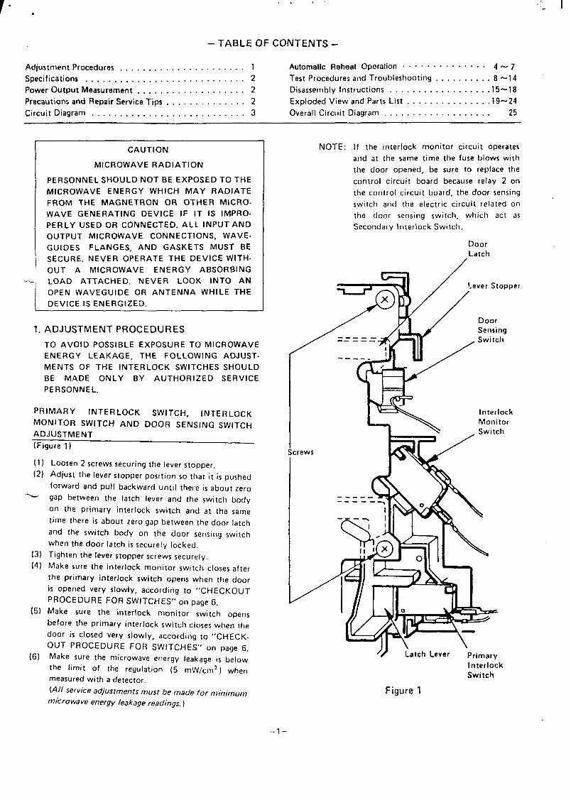
PRIMARY INTERLOCK SWITCH, INTERLOCKMONITOR SWITCH AND DOOR SENSING SWITCH
ADJUSTMENT
(Figure 1)
[1)
(2)
\
(3)
(4)
(5)
(6)
Loosen 2 screws securing the lever stopper.
Adjust the lever stopper position so that it is pushed
forward and pull backward until thele is about zero
gap between the latch lever and the switch body
On the primary interlock switch and at the same
time there is about zero gap between the door latch
and the switch body on the door sensing switch
when the door latch is securely locked.
Tighten the lever stopper screws securely.
Make sure the interlock monitor switch closes after
the primary interlock switch opens when the door
is opened very slowly, according to “CHECKOUT
PROCEDURE FOR SWITCHES” on page 6.
Make sure the interlock monitor switch opens
before the primary interlock switch closes when the
door is closed very slowly, according to “CHECK-
OUT PROCEDURE FOR SWITCHES” on page 6.
Make sure the microwave energy leakage is below
the limit of the regulation (5 mW/cm2 ) when
measured with a detector.
(AI{ service adjustments must be made for minimum
micro wave energy leakage readings. )
NOTE:
-1
/
,rews
/= --
--
If the interlock monitor circuit operates
arsd at the same time the fuse blows with
the door opened, be sure to replace the
control circuit board because relay 2 on
the control circuit board, the door sensing
switch and the electric circuit related on
the door sensing switch, which act as
Secondary Interlock Switch.
DoorLatch
‘1 / !-ever Stopper
F j’”/x
DoorSensing
\ , Switch
‘w~= Swich
InterlockMonitor
/) Latch Lever Primary
InterlockSwitch
Figure 1
–l–
2. SPECIFICATIONS
Rated Power Consumption . . .
Microwave Output . . . . . . .
Frequency . . . . . . . . . . . . . .
Power Supply . . . . . . . . . . .
Rated Current . . . . . . . . . . .
Safety Devices . . . . . . . . . . .
Timer . . . . . . . . . . . . . . . . .
Overall Dimensions . . . . . . . .
Oven Cavity Size . . . . . . . . .
Turn Table Diameter . . . . . . .
Effective Capacity of
Oven Cavity . . . . . . . . . . .
Net Weight . . . . . . . . . . . . .
1400W
700W
(Adjustable 155W through
700W)
2,450 MHz f 50 MHz
230- 240V50HZ
6.0 Amp.
Thermal Protector, Open
at 135°C for Magnetron
Fuse (Cartridge Type 8A)
Primary Interlock Switch
Door Sensing Switch and
Relay 2
Interlock Monitor Switch
Electronic Digital, up to
99 min. 99 sec.
550(W) x 453(D) x 309(H) mm
375(W)X 404(D) x 237(D) mm
360 mm
31 liter
Approx. 20 kg
3. POWER OUTPUT MEASUREMENT
(1) Fill two beakers (glass or plastic) with each one liter
of taP water (about 20° C) and measure the water
temperature. (Use a thermometer with a 1/10
degree gauge. )
(2) Place the beakers side by side in the center of the
glass tray.
(3) Close the door, set the “TIME” for two minutes.(.,2 O(y? in the display window. ) Touch the
“START” key and heat the water exactlv for two
minutes.
(4) Take the beakers out, immediately stir the water
and measure the water temperature respectively.
(5) Calculate the temperature rise of water in each
beaker. Then calculate the average value of two
temperature rises.
Output power can be calculated by the equation;
Power output (W) = 70 x At
Where At is an average temperature rise in degrees
Centigrade.
(6) Output shall be in the following range:
Average temperature rise Power output
Minimum 9.O”C 630W
Maximum 11.5°c 805W
(7) Power output is affected by the line voltage under
load. For correct power output measurement, the
line voltage under load must be 240t 1 volts.
4. PRECAUTIONS
PRELIMINARY
A. SINCE NEARLY
AND REPAIR SERVICE TIPS
4,OOO VOLTS EXISTS IN SOME
CIRCUITS OF THIS MICROWAVE OVEN, REPAIRs
SHOULD BE CARRIED OUT WITH GREAT CARE.
B. TO AVOID POSSIBLE EXPOSURE TO MlCROWAVE
ENERGY LEAKAGE, THE FOLLOWING PRE-
CAUTIONS MUST BE TAKEN BEFORE SERVICING.
(1) Before the power is applied:
(a) Open and close door serveral times to make sure the
primary interlock switch, the interlock monitor
switch and the door sensing switch operate proper-
ly. (Listen for the clicking sound from the switches. )
Make sure the interlock monitor switch closes after
the primary interlock switch is opens when the door
is opened.
(See pages 1 and 6)
(b) Make sure the perforated screen and the choke di-
electric of the door are correctly mounted.
(2)
(a)
(b)
(3)
(a)
(b)
(c)
(d)
(e)
(f)
(4)
(a)
(b)
(c)
(d)
(e)
The
After the power IS applied:
Open and close the door to see if the interlock
mechanism operates properly.
Check microwave energy leakage with a leakage
detector and confirm the energy leakage is below 5
mW/cm2.
Do not operate the unit until it is completely re-
paired, if any of the following conditions exists.
Door does not close firmly against the cavity front.
The hinge is broken.
The choke dielectric or the door seal is damaged.
The door is bent or warped, or there is any other
visible damage to the oven that may cause micro-
wave energy leakage.
NOTE: Always keep the seal clean.
Make sure that there are no defective parts in the
interlock mechanism.
Make sure that there are no defective parts in we
microwave generating and transmission assembly.
(especially waveguide)
The following items should be checked after the
unit is repaired:
The interlock monitor switch is connected correctly
and firmly.
The magnetron gasket on the magnetron is properly
positioned.
Waveguide and oven cavity are intact (no leakage of
microwave energy).
The door can be properly closed and the safety
switches work properly.
The oven must be stopped when the door is opened
or the time is up.
oven must not be operated with any of the above
components removed or bypassed.
–2–
,,!
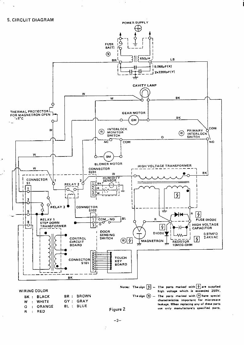
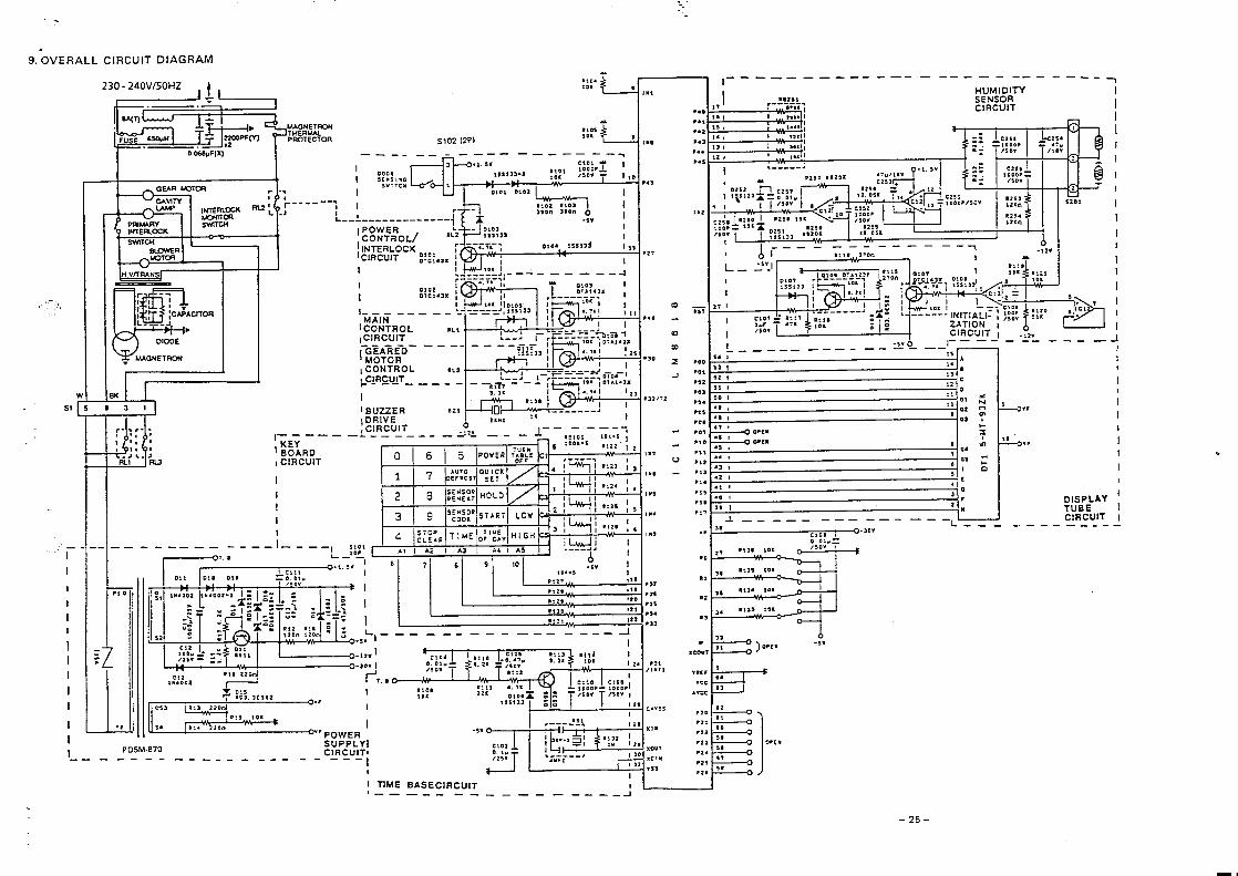
5. CIRCUIT DIAGRAMPoWER SUPPLY
9 =
-$l!
-1 [-
FUSE I I I
8A(T) I L–=–-J 1II
i
7t5”c
II CAVITY LAMP
wBK f
I I
I
I
w
THERMAL PROTECTOR
5
FOR MAGNETRON OPEN
J“ { ‘ C*’
GEAR MOTOR
GMBK
\
r-W~.__——-—\ ~~NNECTOR
.—-— — ——-
1 2
@ LwTr’&k?K\
SWITCH@ !’fwwci
o SWITCH
NC
4+BLOWER MOTOR
CONNECTORHIGH VOLTAGE TRANSFORMER
f————-—— —- —____ __mS201 w i
A.+
i BK-—— . . .
I
[J--I
El I
I
i
:OM
\NO
.) RELAY 2 (
II 3
I CONNECTOR L —-—— ——
- -i
——- — —— < )- J
I 5 S102
. Ii RELAY 1
●
RSTEP 00WN
FUSE DIOOE
I TRANSFORMER~——–_T
I10 I DOOR
‘ c.
, SENSINGDIODE
I
0.97MF0
ICONTROL
ISWITCH
ICIRCUIT
/ BOARD II
10MEG.OHM
I/II
,\ c
CONNECTORI I
JSlol
II1-
L ———— - J-—— ———— ———— ——— —
1 BK I
WIRING COLORNotas: Th.sign @ - Th. parts markad with ❑ ar. s.rw,i.d
high voltage which is ●xcaadad 250V.
BK : BLACK BR : BROWN Tha sign @ - The Patts markad with @ hava special
w : WHITE GY : GRAY charactcristia important for microwav-
o : ORANGE BL : BLUEIoakage. When replacing sny of thase parts
R : REDuse only manufactur,’s spacifiad parts.Figure 2
–3-
6. AUTOMATIC REHEAT OPERATION
Automatic reheat is controlled by a humidity sensor.
Power level, reheating time, doneness temperature and
quantity of food donot need to beset.
The humidity sensor detects moisture asit escapes from
the food being reheated.
The microprocessor on the circuit board receives the
signals from the sensor and controls the power level and
the reheatng time automatically.
A. HOW THE HUMIDITY SENSOR WORKS FOR “AUTO-
MATIC REHEAT”
The humidity sensor is located on the left rear ofOven Cavitv. (Figure 5)
This sensor detects an amount of moisture as it escapes
from the food and the amount of moisture is closely
related to the doneness of the food being reheated.
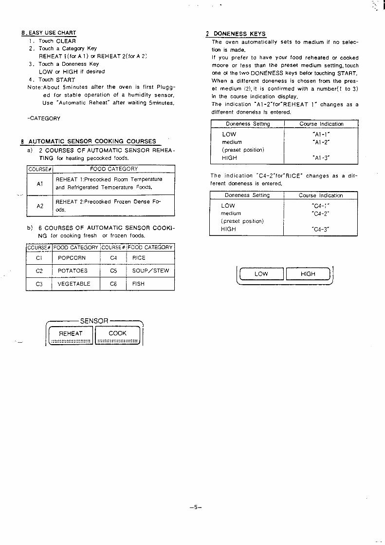
The sensor is composed of two thermistors. One is
sealed in a dry air compartment and the other is in an
open compartment. (Figure 4)
The both thermistors are heated by themselves at about
200°C when the oven is plugged in. The thermistor in
a dry air compartment is cooled by the influence of air
temperature and the thermistor in an open compartment
is cooled by not only the air temperature but also evapo-
ration of the moisture in the air around the sensor.
If the sensor is in a dry air, the both thermistors in the
sensor have the same resistance value, regardless of the
air temperature.
But if it is in a moist air, the thermistor in an open com-
partment will be cooled more by evaporation of the
moisture and the resistance value will increase, compared
with the thermistor in a dry air compartment.
This develops a difference between both thermistors in
resistance value.
The sensor sends that information to the micro com-
puter, which calculates and automatically adjusts the
power level and remaining operating time.
J=ii3=-o---
==0:=-=- _-0.
Q
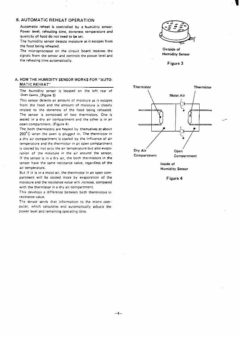
Outside of
Humidity Sensor
Figure 3
Thermistor Thermistor
\ Moist Air /
Dry Air- Open’
Compartment Compartment
Inside of
Humidity Sensor
Figure 4
–4–
.
B . EASY USE CHART 2 DONENESS KEYS1. Touch CLEAR
2. Touch a Categcxy Key
REHEAT l(for A 1) mREHEAT2(fof A2)
3. Touch a Dcneness Key
LOW M HIGH if desired
4. Touch START
Note: About 5minutes after the oven is first Plugg-
ed for stable operation of a humidity sensor.
Use ‘Automatic Reheat- after waiting 5minutes.
-CATEGORY
8 AUTOMATIC SENSOR COOKING COURSES ‘
a) 2 COURSES OF AUTOMATIC SENSOR REHEA -
-.
TING fcr heating pecooked focds.
~
REHEAT 1:Preccoked Rcorn Temperature
and Refrigerated Temperature Food..
REHEAT 2:Preccmked Frozen Dense Fo-A2 ~s
b) 6 COURSES OF AUTOMATIC SENSOR COOKl-
NG for cooking fresh or frozen fcxxk.
couRsE# lFOOD CATEGORy ]COURSE#l FOOD CATEGORY
The oven automatically sets to medium if no selec-
ticm is made.
If you prefer to have your food reheated or cooked
moore or less than the preset medium setting, touch
cne of the two DONENESS keys befcx tcuching START.
When a different doneness is chosen from the pres-
et medium (2), it is confirmed with a number(l to 3)
in the course indication display.
The indication ‘Al -2-for-REHEAT 1- changes as a
different doneness is entered.
Dcmeness Setting Ccurse Indication
LOW -Al-l-
medium ‘Al -2-
(preset position)
HIGH ‘Al -3-
The indication ‘C4-2”for-Rl CE- changes as a dif -
ferent doneness is entered.
1 Doneness Setting Course Indicationt
LOW -C4-1 “medium ‘C4-2-
( preset position)
HIGH “c4-3-
Imml
–5–
C. POINT TO REMEMBER
● Before using Auhxnatic Sensw Programs...
The oven should be plugged into power supply for
more than five minutes.
Wipe off any noticeable moisture or spillovers fr-
om the wen.
If the inside of the oven is very warm, wait until
it cools down.
Automatic Sensor may not operate properly if the
room temperature is higher than 95”F(35°C ).
● Do not touch STOP/CLEAR, once cooking starts.
This will void the Automatic.
Sensor program and the food will need to be finis-
hed by using regular micrcwave operation.
● Make sure to use the correct food category or reh-
eat course for the food that is to be reheated or
cooked.
. The oven door must remain closed while display sh-
ows course indication (- C1-2-, -C2-2., -A1 -2-
and so cm) unless ‘PAUSE- appears in the display.
If the door is opened, -Err- (error) will flash in
the display. This indicates the operation must be r-
reprogrammed into the oven. NOTE: The oven door may
be opened when time countdown appears in the disp-
lay.
. Automatic sensor cannot be used with other functi-
ons such as Time, temperature probe, Auto Defrost.
When the Temperature Probe is plugged in and Auto-
matic Sensor Cooking is started, the word ‘Probe”
will flash and the oven will not work.
–6–

7. INTERNAL AIR FLOW
The blower motor always runs during cooking or reheating. The air from the blower divides into two ways as shown in
Figure 5. This prevents the sensor from being affected by the warm air which has no relation with the doneness of food
being reheated.
(1) Air flow for rotating the stirrer fan
Air flow is shown by solid arrows in Figure 5.
The air from the blower cools the magnetron and
becomes warm. The warm air goes into a stirrer
compartment to rotate the stirrer fan.
(2) Air flow for carrying the moisture escaping from
food to the sensor
Air flow is shown by shaded arrows in Figure 5.
The air from the blower motor goes into cavity
inside and carries the moisture escaping from the
food being reheated to the sensor.
CAUTIONS:
- The stirrer cover inside of the oven cavity acts as an airpartition between the air for rotating the stirrer fan and
the air for carrying the moisture escaping from food to
the sensor. The stirrer cover must be secured p,”operly.— The oven cabinet (outer wrap) acts as an air wide. The
stirrer fan may not rotate properly and the sensor may
not detect the moisture escaping from the food properly
while the oven cabinet is removed.
AirHumidity Sensor
Exhaust/
Figure 5
–7–
Air
Intake
I Blower
?\, , RFilament Windings
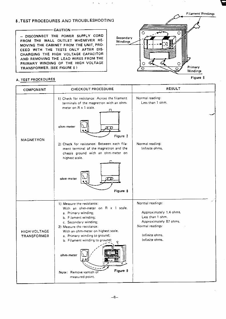
8 .TEST PROCEDURES AND TROUBLESHOOTING /“1
rc””’’””~DISCONNECT THE POWER SUPPLY CORD
FROM THE WALL OUTLET WHENEVER RE-
MOVING THE CABINET FROM THE UNiT, PRO-
CEED WITH THE TESTS ONLY AFTER DIS-
CHARGING THE HIGH VOLTAGE CAPACITOR
AND REMOVING THE LEAD WIRES FROM THE
PRIMARY WINDING OF THE HIGH VOLTAGE
TRANSFORMER. (SEE FIGuRE 6 )
A. TEST PROCEDURES
COMPONENT
MAGNETRON
HIGH-VOLTAGE
TRANSFORMER
s
CHECKOUT PROCEDURE
1) Check for resistance: Across the filament
terminals of the magnetron with an ohmm-
eter on R x i scale.
1 r
ohm-meter
w
2) Check for resistance: Between each fila-
ment terminal of the magnetron and the
chassis ground with an ohm-meter on
highest scale.
ohm-meter
G
Q
Figure 8
1 ) Measure the resistance:
With an ohm-meter on R x 1 scale.
a. Primary winding;
b. Filament winding;
c. Secondary winding;
2) Measure the resistance:
With an ohm-meter on highest scale.
a. Primary winding to ground;
b.
ohm-
Note:
measured point.
Figure 6
RESULT
Normal reading:
Less than 1 ohm.
Normal reading:
Infinite ohms.
Normal readings:
Approximately 1.4 ohms.
Less than 1 ohm.
Approximately 87 ohms.
Normal readings:
Infinite ohms.
Infinite ohms.
–8–
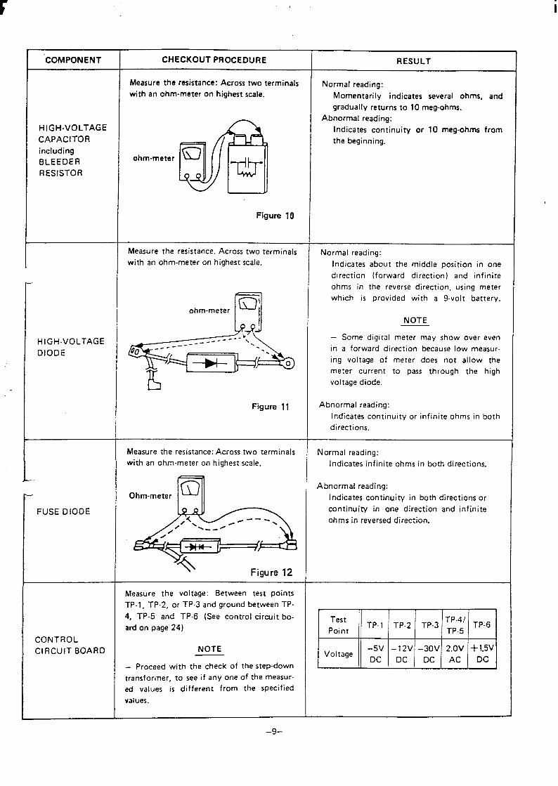
‘COMPONENT
HIGH-VOLTAGE
CAPACITOR
including
BLEEDER
RESISTOR
HIGH-VOLTAGE
DIODE
t-
FUSE DIODE
CONTROL
CIRCUIT BOARD
CHECKOUT PROCEDURE
Measure theresistance: Across two terminals
with an ohm-meteron highest scale.
Figure 10
Measure the resistance. Across two terminals
with an ohm-meter on highest scale.
ohm-metern
a
bFigure 11
Measure the resistance: Across two terminals
with an ohm-meter on highest scale.
Ohm-metern
Measure the voltage: Between test points
TP-1, TP-2, or TP.3 and ground between TP-
4, TP-5 and TP-6 (See control circuit bo-
ard on page 24)
NOTE
Proceed with the check of the step-down
transformer, to see if any one of the measur-
ed values is different from the specified
values.
RESULT
Normal reading:
Momentarily indicates several ohms, and
gradually returns to 10 meg-ohms.
Abnormal reading:
Indicates continuity or 10 megohms from
the beginning.
Normal reading:
Indicates about the middle position in one
direction (forward direction) and infinite
ohms in the reverse direction, using meter
which is provided with a 9-volt battery.
NOTE
– Some digital meter may show over even
in a forward direction because low measur-
ing voltage of meter does not allow the
meter current to pass through the high
voltage diode.
Abnormal reading:
Indicates continuity or infinite ohms in both
directions.
Normal reading:
Indicates infinite ohms in both directions.
Abnormal reading:
Indicates continuity in both directions or
continuity in one direction and infinite
ohms in reversed direction.
Test
Point‘P-4’ TP-6
‘p” ‘ ‘P-2 ‘P.3 TP-5
–5V –12V –30V 2.OV +1.5VVoltage Dc DC Dc Ac Dc
–9-
-. ,’
.
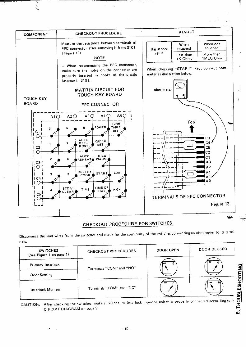
COMPONENT
TOUCH KEY
BOARD
CHECKOUT PROCEDURE
Measure the resistance between terminals of
FPC connector after removing i\ from SIO1.
(Figure 13)
NOTE
When reconnecting the FPC connector,
make sure the holes on the connector are
properiy inserted in hooks of the
fastener in S101.
MATRIX CIRCUIT FORTOUCH KEY BOARD
FPC CONNECTOR
plastic
---- —— —.. — —-—— ——— ——— . -ii
-1
I
I
I
IIIII
RESULT I
EEEazaWhen checking “START” key, connect ohm-
meter as illustration below.
aG3ohm-meter
Top \\-
F-/t---TERMINALS OF FPC CONNECTOR
Figure 13
CHECKOUT PROCEDURE FOR SWITCHES
Disconnect the lead wires from the switches and check for the continuity of the switches connecting an ohmmeter to its termi.
nals.
1SWITCHES
(See Figure 1 on page 1)CHECKOUT PROCEDURES DOOR OPEN DOOR CLOSED I
Primary InterlockTerminals “COM” and “NO”
Door Sensing
Q @;
Interlock Monitor Terminals “COM” and “NC”
I
a @!
CAUTION: After checking the switches,make sure that the interlock monitor switch is ProPerl Y connec[ed according tO [h s
CIRCUIT DIAGRAM on page 3.:
m“
–lo–
,; !:
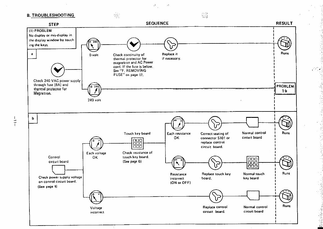
B. TROUBLESHOOTING ,..,....!. ...
. ,
.....1,, .... . ...’.!
STEP SEQUENCE RESULT
1) PROBLEMI
10 display or mis.display in
II
~edisplay window by touch,
I m
I ,1,
0 24019 the keys.
@
I
t @It
Ja o Vol
o–1vCheck continuity. of Replace it i Runs
thermal protector for if necessary. I
magnetron and AC Power1
cord. If the fuse is below.I
See “F. REMOVINGII
FUSE” on page 17. I1
Check 240 VAC power supply ithrough fuse (8A) and
t!wrnd pr9bxh2r fw[ PROBLEM
.- ..= ..._
Magnetron,.—...— . . __ -.. . .- . .. . . . . .. . . . . ....= ----- . ..
I 14?1’
240 vOltI
I
I
I
,,’
:
‘.
,,,,
.:,,,.,
,’.‘,,,,
,;’,
,,:.
‘.’.,,
,., -..; ‘.*.’.
,,.. .
.,
:.’,.
,>
. . .,
,,
.,,,:
bI
Conlrol
circuit board
Check power supply voltage
on control circuit board.
(See page 9)
Touch key board
? *000000000
Each voltage Check resistance of
OK touch key board,
(See page 6)
1
@
l,’
I‘@I
Each resistance Correct seating of Normal control I Runs
OK connector S101 or circuit board II
replace control I
circuit board. III
r I
@
000000000 I
I
Resistance Replace touch key Normal touchII Runs
incorrect board, key board I
(ON or OFF)IIII
@
I*”‘@II
Voltage Replace control Normal control ~ Runs
Incorrect circuit board. circuit board IIII
,..,.,..’,,,
,:
.,,,
.’, .
.,,,.‘.‘.,,.,.:,,.,
,!
,,.
. . . .
.:.
.
}..
., ..;.,,
‘,,
,.:,.
“. ,,,:.,, :.:,.;
9
CTcn RF~ll FNCF RESULT
,,‘,, .,., ,
.,.;.
.;
,,
,,, ,
.“, :,,.,,.:.
. . .,.
,.
,.
..:. :
,’,’,,.’...,.,,
i,
,’. :
.’,,,..,,
.,, ,.,,,..,
,.,’..’, ,,.
.’ ..”,,,.,,,,,.,,
,,,,.
,,,,,
,,.,,.,.,.. ..,,
,,,,:,.
.’,“.,.,.,
.,,,.’.
,,.’,’,,,.,,,. ,.,. ,,..
:,.‘, .’... ,... ,,.’. .
Ih)
I
oiLr --------- --
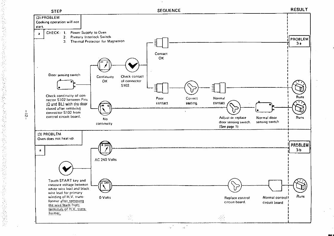
2) PROBLEMII
hoking operation will notII
tart. I
CHECK: 1. Power Supply to OvenI
a2, Primary Interlock Switch
I
3 Thermal Protector for Magnetron
-a
II PROBLEM
3-alb
ContactI1
OK II
i
Door sensing switch1
Continuity Check contactI
D
Io OK of connector
-a—@-a
1~1,
●S102. I
Check continuity of con.I‘@
nector S102 between Pins
(0 W( DL) wilh tho door
Poor Correct NormalI
cQntact seating, contactclosed after rerrtthrin~connector S102 from
‘-’-” ‘-” ‘“’ :
.._. _@ (–). .~@
control circuit board.No AdjusI or replace Normal door 1 Rum
continuity door sensing switch. sensing switch i(See page 11 1
(3) PROBLEM
,
Oven does not heat up.
II1,
I ~~~~L~ti
a I 3b
AC 240 Volts
IIIII
Touch START key and
:I ~)
measure voltage between
@
1
J@
.
white wire Iea[l and blackwire lead for primary
I
winding of H.V. trans.I
o volts Replace control Runs
tormer afler removingNormal control I
——. —.. —..the wire le~ds from
circuit board, circuit board
termtnals of H,V. trans.
:I—.—
former. I—— I,, .:’,.’ . . . I

“-
}..iLc..,.:uLiLLz:au1-U
-i-f
-------—
----
----------
‘1
-.—.
.--—+
+-—
-------
---------
----
6‘--lI\/
.-
1I
–13-
‘,..,,
SEQUENCE RESULT
...,.,,,.......:,
.’
,,,:.’..
,,,
‘, :
,,,,,.
.’,.,,,.’.
,, .’,,
,,,.,,,!“
.,,,
,!,’.,,,
,::,”,,,,.. . .
,,“,.,,.’.
,,,,,
.,..’
,,,,,,,
.’.,’: .,.’:,.’,
..,,..,.,.:.
,,..,.,.,.:,,
‘.’..,.,.,.,..,,,,,
;,,,,,,“.’.,,,
:,.,,.....,.,.,...
:,:.,,. .,
. ..’.:.,.
.,.’
:.,.,,
. .. . .,,
,:.’,. ,.,...,
. . . ..,..
UVLV
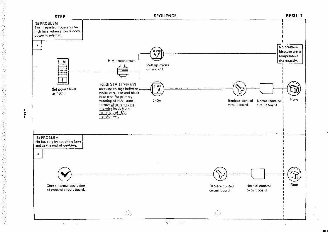
I5) PROBLEM‘he magnetron operates on
I
Iigh level when a lower cook
I
I}ower is selected. I
Ia
m
No problem.
Measure water
‘u
temperature
aH.V. transformer. rise exactly.
E&
Voltage cycleson and off.
iII
mI
Towh START key andI
@
I a’.: ‘tSet fmwei level fiie~stire volfage bebA@en
‘“” - ‘“”” ‘“- ‘“--”” -
. . ..—.-. . -,.
at “50”. white wire lead and black ‘@I
wire lead for primary I
winding of H.V. trans- 240V Replace control Normal control 1 Runs
former after removirq circuit board. I
the wire leads fromcircuit board ,
terminals of H.V.I
transformer.III
II1
[6) PROBLEM I
No buzzing by touching keys I
and at the end of cooking. I
~-
!II1II
@
: *’”.
I‘@
Check normal operation
I
Replace control Normal control I Runs
of control circuit board. Icircuit board. circuit board I
II
:
. ,, .,
.’, , ,.:~ :.,, . . ... It
I
‘1,,
Ell
9. Dl$AssEMf3LY INSTRUCTIONS
●
●
A.
OVEN MUST BE DISCONNECTED FROM ELECT-
RICAL OUTLET WHEN MAKING REpLACEMENTS,
REPAIRS, ADJUSTMENTS AND CONTINUITY
CHECKS BEFORE PROCEEDING WITH ANY RE-
REPAIR WORK AFTER DISCONNECTING. WAIT AT
LEAST I MINUTE, UNTIL THE CAPACITOR IN THE
HIGH-VOLTAGE AREA HAS FULLY DISCHARGED.
WHEN REPLACING ANY DOOR MICROSWITCH,
REPLACE WITH THE SAME TYPE SWITCH SPECIFIC
ED ON THE PARTS LIST.
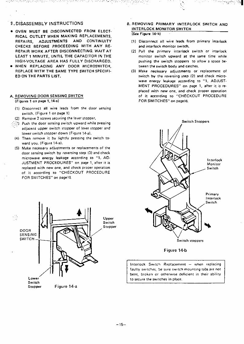
REMOVING DOOR SENSING SWITCH
(Figures 1 on page 1, 14-a)
(1)
(2)+.7 )
.. ““
(4)
(5)
Disconnect all wire leads from the door sensing
switch. (Figure 1 on page 1)
Remove 2 screws securing the lever stopper.
Push the door sensing switch upward while pressing
adjacent upper switch stopper of lever stopper and
lower switch slopper down (Figure 14-a).
Then remove it by lightly pressing the switch to-
ward you. (Figure 14-a).
Make necessary adjustments or replacements of the
door sensing switch by reversing step (3) and check
microwave energy leakage according to ‘“l. AD-
JUSTMENT PROCEDURES” on page 1, after it is
replaced with new one, and check proper operation
of it according to “CHECKOUT PROCEDURE
FOR SWITCHES” on pagelo.
-.
Lower”SwitchStopper Figure 14-a
UpperSwitchStopper
..
B. REMOVING PRIMARY INTERLOCK SWITCH AND
INTERLOCK IMONITOR SWfTCfi
(See Figure }+b) -
(1)
(2)
(3)
Disconnect all wire leads from primary interlock
and interfock monitor switch.
Pull the primary interlock switch or interlock
monitor switch upward at the same time while
pushing the switch stoppers to allow a space be-
tween the switch body and catches.
Make necessary adjustments or replacement of
switch by the reversing step (2) and check micro-
wave energy leakage according to “1. ADJUST-
MENT PROCEDURES” on page 1, after it is re-
placed with new one, and check proper operation
of it according to “CHECKOUT PROCEDURE
FOR SWfTCHES’” on pageltl
Switch Stoppers
x--I fcterlockMonitor
, Switch
%/ I PrimaryInterlock
11 ,1 Switch
Switch stoppers
Figure 14-b
~
Interlock Swilch Replacement – when replacing
faulty switches be sure sw]tch mounting tabs are not
bent, broken or o:herwlse deflclent In their ablllty
to secure the switches in place.
-15–
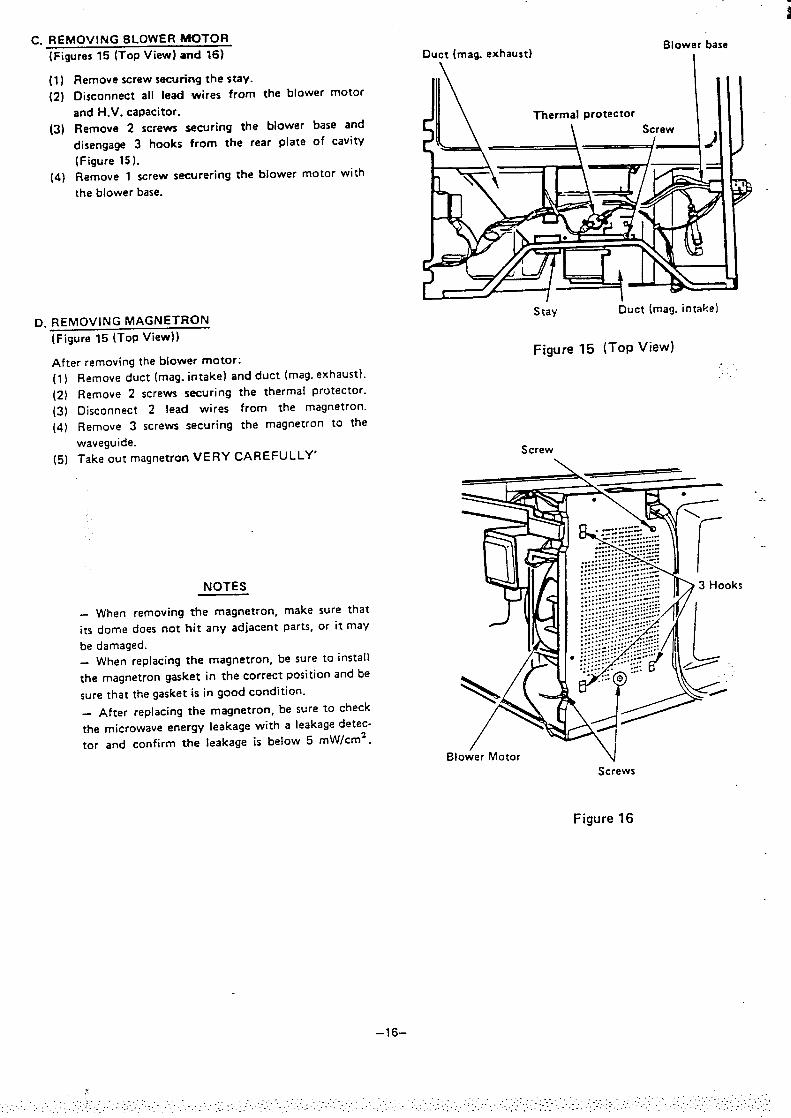
C. REMOVING BLOWER MOTOR
(Figures 15 (TOP View) and 16)
(1) Remove screw securing the stay.
(2) Disconnect all lead wires from the blower motor
and H.V. capacitor.
(3) Remove 2 screws securing the blower base and
disengage 3 hooks from the rear plate of cavity
(Figure 15).
(4) Remove 1 screw securering the blower motor with
the blower base.
D. REMOVING MAGNETRON
(Figure 15 (TOP View))
After removing the blower motor:
(1)
(2)
(3)
(4)
(5)
Remove duct (msg. intake) and duct (msg. exhaust).
Remove 2 screws securing the thermal protector.
Disconnect 2 lead wires from the magnetron.
Remove 3 screws securing the magnetron to the
waveguide.
Take out magnetron VERY CAREFULLY’
NOTES
When removing the magnetron,
its dome does not hit any adiacent
be damaged.
make sure that
parts, or it may
When replacing the magnetron, be sure to install
the magnetron gasket in the correct position and be
sure that the gasket is in good condition.
– After replacing the magnetron, be sure to check
the microwave energy leakage with a leakage detec-
tor and confirm the leakage is below 5 mW/cm2.
Duct (msg. exhaust)Blower base
\ I
L , / IStay I$uct (msg. intake)
Figure 15 (TOP view)
... .
Screw\
&~’r;:::;.::::;..::::;::..........................-.....................4/4/:..::::....:....-.::.::::............Z..
.:::- . . . . . . . . . . ..::::::......:::::--.::.<::. . . . . . . . . . . . . . . . .: . . . . . .. . . . . . . . . .: :::::::..:::::::::~
:::....:::;. .::::.:----............. ......................... ...::::... lb3 Hooks.:: :..- ...-.. . . .. ... . . .......... ....
Blower Motor \Screws
Figure 16
.-.
..
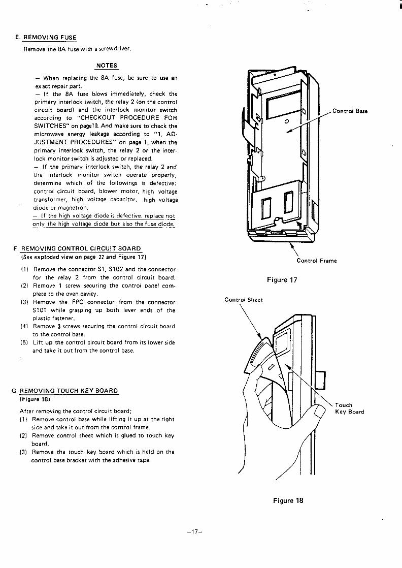
E. REMOVING FUSE
Remove the 8A fuse with a screwdriver.
NOTES
— When replacing the 8A fuse, b+?sure to use an
exact repair part.
If the 8A fuse blows immediately, check the
primary interlock switch, the relay 2 (on the control
circuit board) and the interlock monitor switch
according to “CHECKOUT PROCEDURE FOR
SWITCHES” on pagel O. And make sure to check the
microwave energy leakage according to “1. AD-
JUSTMENT PROCEDURES” on page 1, when the
primary interlock switch, the relay 2 or the inter-
lock monitor switch is adjusted or replaced.
– If the primary interlock switch, the relay 2 and
the interlock monitor switch operate properly,
determine which of the followings is defective:
control circuit board, blower motor, high voltage
transformer, high voltage capacitor, high voltage—diode or magnetron.
– If the high voltage diode is defective, replace not
only the high voltage diode but also the fuse diode,
F. REMOVING CONTROL CIRCUIT BOARD
(See exploded view on page 22 and Figure 17)
(1)
(2)
(3)
(4)
(5)
Remove the connector S1, S102 and the connector
for the relay 2 from the control circuit board.
Remove 1 screw securing the control panel com-
plete to the oven cavity,
Remove the FPC connector from the connector
S101 while grasping UP both lever
plastic fastener.
Remove 3 screws securing the control
to the control base.
Lift up the control circuit board from
and take it out from the control base.
ends of the
circuit board
its lower side
G. REMOVING TOUCH KEY BOARD
(Figure 18)
After removing the control circuit board;
(1)
(2)
(3)
Remove control base while lifting it up at the right
side and take it out from the control frame.
Remove control sheet which is glued to touch key
board.
Remove the touch key board which is held on the
control base bracket with the adhesive tape.
Control Base
Control Frame
Figure 17
Control Sheet
TouchKey Board
–17–
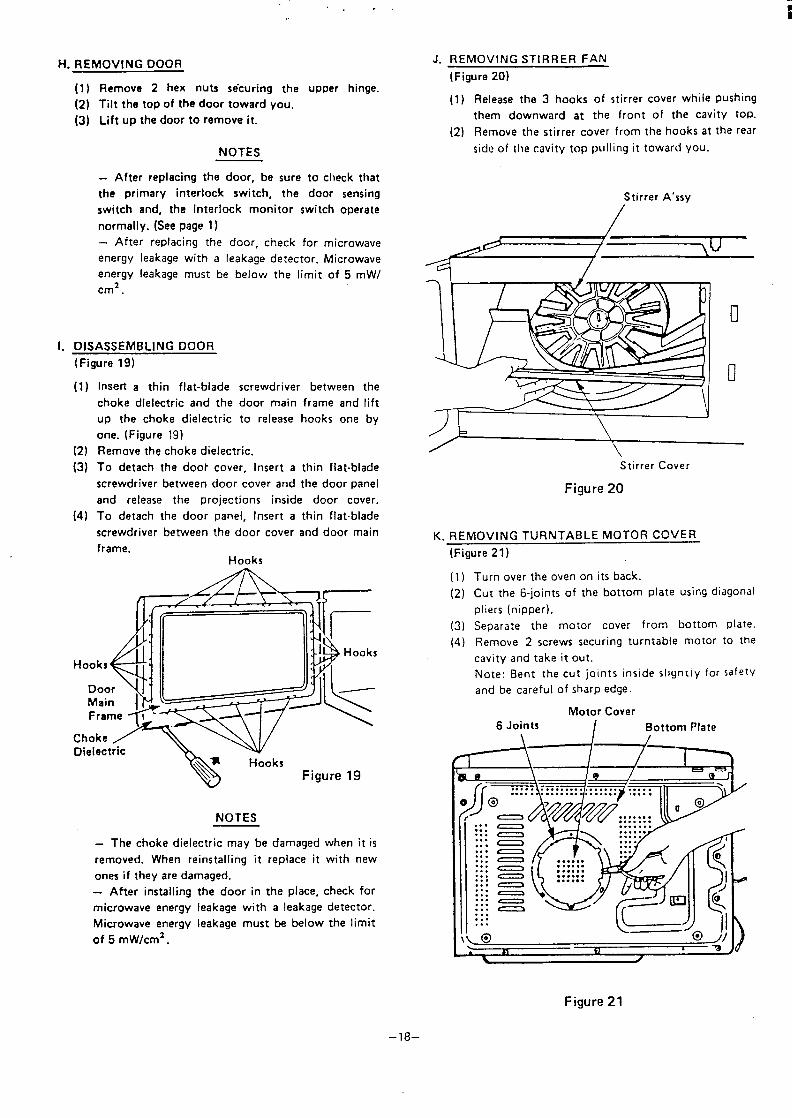
H. REMOVING DOOR
1.
(1) Remove 2 hex nuts seturing the upper hinge.
(2) Tilt the top of the door toward you.
(3) Lift up the door to remove it.
NOTES
- After replacing the door, be sure to check that
the primary interlock switch, the door sensing
switch and, the interlock monitor switch operate
normally. (See page 1)
- After replacing the door, check for microwave
energy leakage with a leakage detector. Microwave
energy leakage must be below the limit of 5 mW/
cmz.
DISASSEMBLING DOOR
(Figure 19)
(1)
(2)(3)
(4)
Insert a thin flat-blade screwdriver between the
choke dielectric and the door main frame and lift
up the choke dielectric to release hooks one by
one. (Figure 191
Remove the choke dielectric.
To detach the doot cover, Insert a thin flat-blade
screwdriver between door cover and the door panel
and release the projections inside door cover.
To detach the door panel, Insert a thin flat-blade
screwdriver between the door cover and door main
frame.Hooks
Hooks
DoorMain I
ChokeDielectric
NOTES
– The choke dielectric may be damaged when it is
removed. When reinstalling it replace it with new
ones if they are damaged.
- Atter installing the door in the place, check for
microwave energy leakage with a leakage detector.
Microwave energy leakage must be below the limit
of 5 mW/cm2.
J. REMOVING STIRRER FAN
(Figure 20)
(1) Release the 3 hooks of stirrer cover while pushing
them downward at the front of the cavity toP.
(2) Remove the stirrer cover from the hooks at the rear
side of the cavity top pulling it toward you.
Stirrer A’ssy
/ \,
\Stirrer Cover
Figure 20
K. REMOVING TURNTABLE MOTOR COVER
(Figure 21)
(1)
(2)
(3)
(4)
Turn over the oven on its back.
Cut the 6-joints of the bottom plate using diagonal
pliers (nipper).
Separate the motor cover from bottom plate.
Remove 2 screws securing turntable motor to the
cavity and take it out.
Note: Bent the cut joints inside slignt[y for safety
and be careful of sharp edge.
Motor Cover
6 Joints / Bottom Plate
\ /
Figure 21
–18–
. . .i
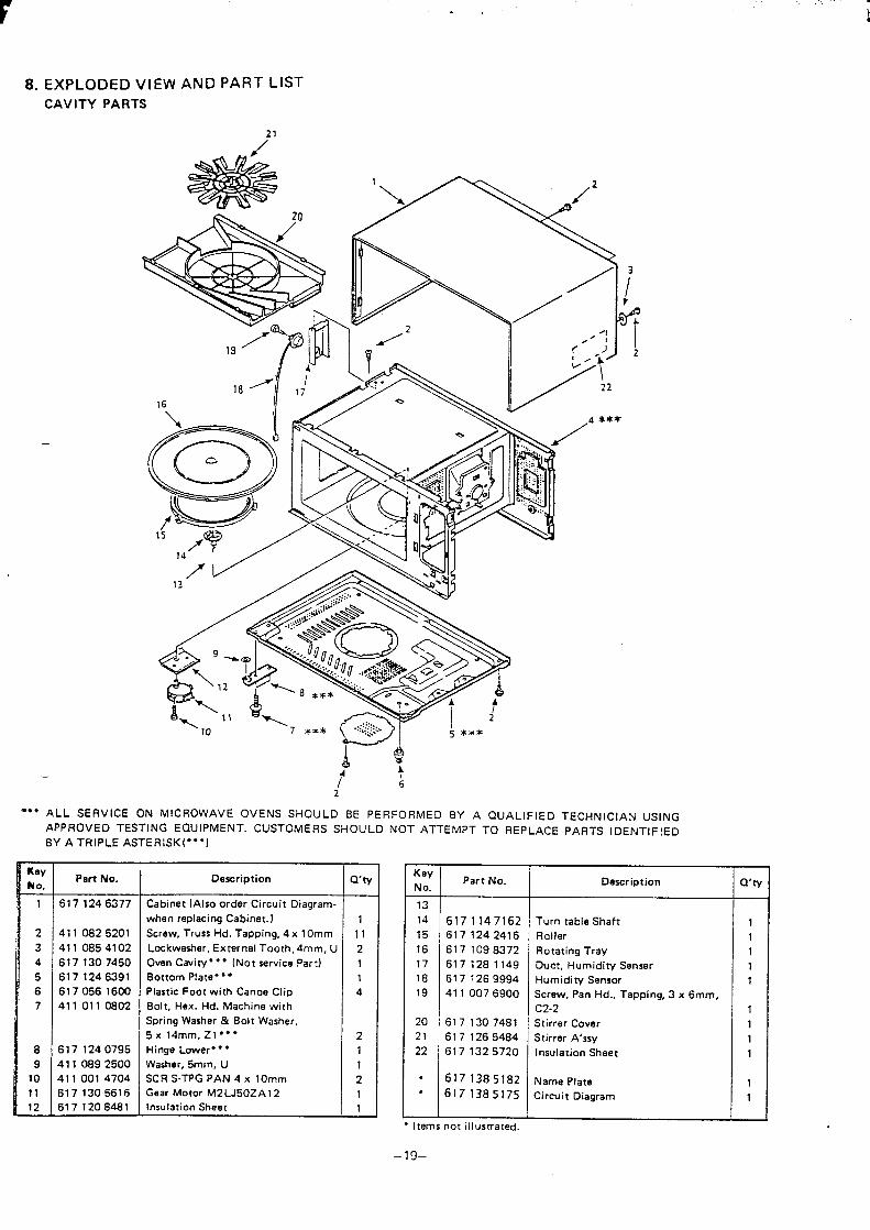
8. EXPLODED VIEW AND PART LIST
CAVITY PARTS
21
a
16 II //
—
*** ALL SERVICE ON MICROWAVE OVENS SHOLJLD BE PERFORMED BY A QUALIFIED TECHNICIAN USING
APPROVED TESTING EQUIPMENT. CUSTOMERS SHOULD NOT ATTEMPT TO REPLACE PARTS IDENTIFIED
BY ATRIPLE ASTER ISK(***)
icyNo.1
234
5
6
7
8
9
10
11
12—
Part No.
6171246377
411 0825201
411 0654102
6171307450
6171246391
6170561600
411 0110802
6171240795
4110892500
411 001 4704
6171305616
617 120 B481
Description Q’ty
Cabinet (Also order Circuit Diagram-
when replacing Cabinet. J 1Screw, Truss Hd. Tapping, 4 x 10mm 11
Lockwasher, External Tooth, 4mm, U 2
Own Cavity*** (Not service Part) 1
Bottom Plate” ● “ 1Plastic Foot with Canoe Clip 4
Bolt, Hex. Hd. Machine with
Spring Washer & Bolt Washer,
5x 14mm, Zl *** 2Hinge Lower” ● ” 1
Washer, 5mm, U 1SCR S-TPG PAN 4 x 10mm 2Gear Motor M2 LJ50ZA 12 1Insulation Sheet 1
KeyPart No.
No.Description a’ty
13
14 6171147162 Turn table Shaft 115 617 1242416 Roller 116 617 1098372 Rotating Tray 117 61712 B1149 Ouct, Humidity Senser 118 617 1269994 Humidity Sensor 119 411 0076900 Screw, Pan Hal., Tapping, 3 x 6mm,
C2-2 120 617 1307481 Stirrer Cover 121 617 1265484 Stirrer A’ssy 122 617 1325720 Insulation Sheet 1
. 617 1385182 Name Plate 1
. 6171385175 Circuit Diagram 1
Items not illusmated.
–19–
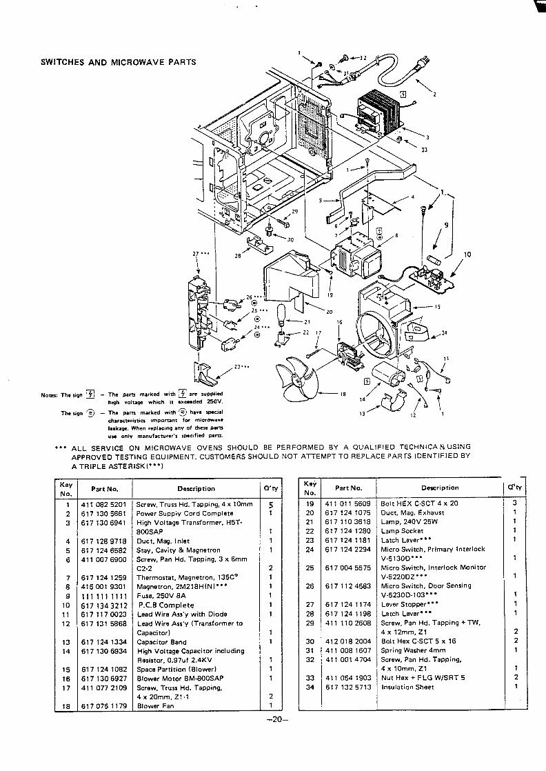
SWITCHES AND MICROWAVE PARTS
Notes: The sign
The sign
Pam marked withvoltaga which is
parts marked with
10
—characteristics important for microwave
.
leakage. When repl=mg any of these partsuse only manufacturer’s specified pare.
““” ALL SERVICE ON MICROWAVE OVENS SHOULD BE PERFORMED BY A QUALIFIED TECHNICAN USING
APPROVED TESTING EQUIPMENT. CUSTOMERS SHOULD NOT ATTEMPT TO REPLACE PARTS IDENTIFIED BY
A TRIPLE ASTERISK””*)
KeyPart No.
NO.Description Q’ty
1 411 0825201 Screw, Truss Hd. Tapping, 4 x 10mm 52 6171305661 Power Supply Cord Complete 1
3 6171306941 High Voltage Transformer, H5T-
800SAP 1
4 6171289718 Duct, Meg. Inlet 1
5 6171246582 Stay, Cavity & Magnetron 1
6 411 0076900 Screw, Pan Hd. Tapping, 3 x 6mm
C2-2 2
7 6171241259 Thermostat, Magnetron, 135C0 1
8 4150019301 Magnetron, 2M218H(N)””” 1
9 1111111111 Fuse, 250V 8A 1
10 6171343212 P.C. B Complete 1
11 6171170023 Lead Wire Ass’y with Diode 1
12 6171315868 Lead Wire Ass’y (Transformer to
Capacitor) 1
13 6171241334 Capacitor 8and 1
14 6171306934 High Voltage Capacitor including
Resistor, 0.97uf 2.4KV 1
15 6171241082 Space Partition (Blower) 1
16 6171306927 810wer Motor BM-800SAP 1
17 411 0772109 Screw, Truss Hd. Tapping,
4 x 20mm, Z1-1 2
18 6170751179 Blower Fan 1
GNo.19
20
21
22
23
24
25
26
27
28
29
30
31
32
33
34
Part No.
411 011 5609
6171241075
6171103618
6171241280
6171241181
6171242294
6170045575
6171124583
6171241174
6171241198
411 1102608
4120182004
411 0081607
411 0014704
411 0541903
6171325713
Description
Bolt HEX C-SCT 4 X 20
Duct, Msg. Exhaust
Lamp, 240V 25W
Lamp Socket
Latch Lever*”*
Micro Switch, PrimaW Interlock
V-5130D*””
Micro Switch, Interlock Monitor
V-5220DZ* “ “
Micro Switch, Door Sensing
V-523 OD-1O3”*”
Lever Stopper**”
Latch Lever*””
Screw, Pan Hd. Tapping + TW,
4x 12mm, Zl
Bolt Hax C-SCT 5 x 16
Spring Washer 4mm
Screw, Pan Hd. Tapping,
4 x 10mm, Z1
Nut Hex + FLG WISRT 5
Insulation Sheet
Q’ty
3
1
1
1
1
1
1
1
1
1
2
2
1
1
2
1
-.—AJ—
. . ..fi
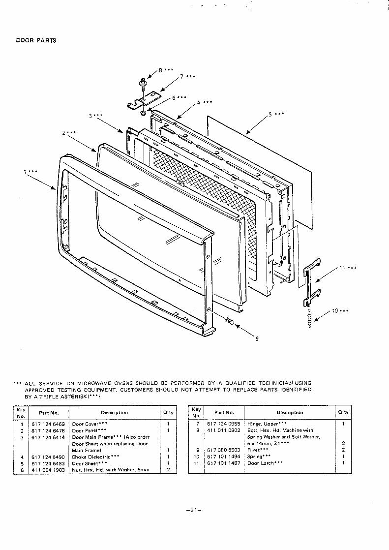
DOOR PARTS
1*’\
‘“A
““” ALL SERVICE ON MICROWAVE OVENS SHOULD BE PERFORMED BY A QUALIFIED TECHNIC IAN.+ USING
APPROVED TESTING EQUIPMENT. CUSTOMERS SHOULD NOT ATTEIVIPT TO REPLACE PARTS IDENTIFIED
BY A TRIPLE ASTERISK**’)
KayPart No.
NO.Description Q’ty
1 6171246469
2 6171246476
3 6171246414
I4 6171246490
5 6171246483
Door Cover*””
Door Panel” ““
Door Main Frame”” ● (Also order
Door Sheet when replacing Door
Main Frame)
Choke Dielectric* ““
Door Sheet” ● ”
11
1
1
1
6 411 0541903 Nut. Hex. Hd. with Washer, 5mm 21 [
Key
No.
7
8
9
10
11
Part No.
6171240955
411 011 0802
6170806503
617101 1494
617101 1487
/“’”
10 ...
Description Q’ty
Hinge, Upper”** 1
Bolt, Hex. Hd. Machine with
Spring Washer and Bolt Washer,
5x14mm, Zl ”** 2
Rivet*”* 2
Spring”** 1
Door Latch ● ● ” 1
–21–
----‘.
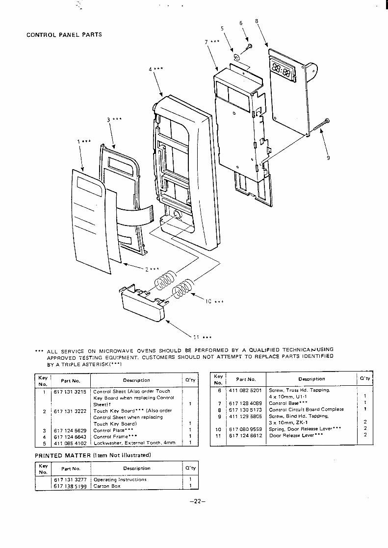
CONTROL PANEL PARTS
● ☛✎
.,.*’\‘N
9
\ 11 ● **
ALL SERVICE ON MICROWAVE OVENS SHOULD BE PERFORMED BY A QUALIFIED
APPROVED TESTING EQUIPMENT. CUSTOMERS SHOULD NOT AITEMPT TO REPLACE
BY A TRIPLE ASTERISK**”)
,
t-’-Key
Part No.NO.
1 6171313215
2 617131 3222
K!ME
Description Qty
Control Sheet (Also order Touch IKey Board when replacing Control
Sheet) 1
Touch Key Board””” (Also order
Control Sheet when replacing
Touch Key Board)
Control Plate”””
Control Frame**”
Lockwasher, External Tooth,4mm
1
1
111
PRINTED MATTER (Item Not Illustrated)1
‘ey I Part No. \ Description I Q’tyNo.
6171313277 Operating instructions 1
617138519~ Carton Box 1
TECHNICANUSING
PARTS IDENTIFIED
KeyPart No.
No.Description Q’ty
6 411 0825201 Screw, Truss Hd. Tapping,II
7 6171284089
8 6171305173
9 411 1295805
I10 6170809559
11 6171246612
4x 10mm, U1-1
Control Base**”
Control Circuit Board Complete
Screw. Bind Hd. Tapping,
3 x 10mm, ZK-1
Spring, Ooor Release Lever”*”
Door Release Lever”” ●
111
2
2
2
–22–
<., “ii
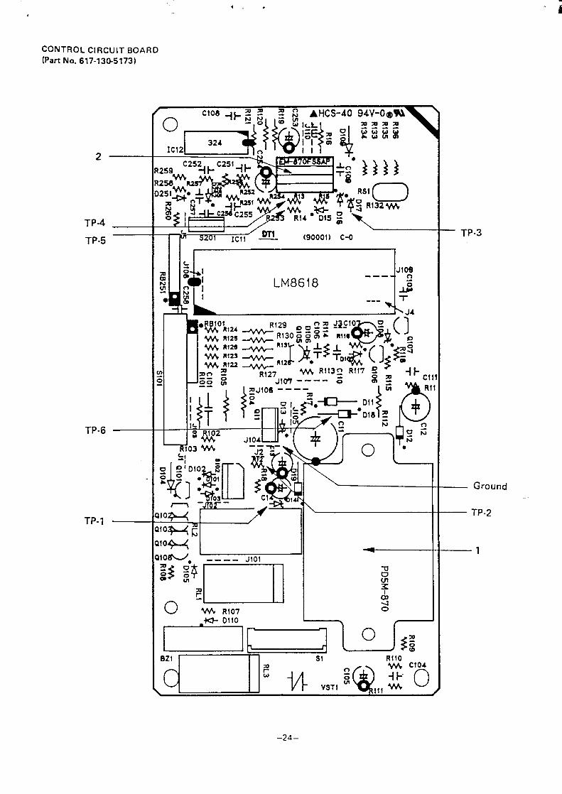
CONTROL CIRCUIT BOARD
(Part No. 617-130-5173)
2.
TP-4
TP-5
TP-6
TP.
— TP-3
— Ground
— TP-2
—1
.,
l———
——
—--
-——
—___
____q–.
_._.--_.
–---.---,
IIh
Ill ...
..
.,..
._Y
t‘
I1.
I:
;:7
;E,
I
t--
~o.
!w”..!:
:~
..
..
..
..
..
..
..
..
II
.-J.
_--_-l
.,,,I
B19BW1
t~olI1IIIIIIII
-J
““IWW
-I“’“‘
0mN
It
3CJ
,I
iiI_–__-__
–------l,.-
.-1.
!,..
m“
,...

SANYO NEW ZEALAND LTD