𝒉𝒉𝒉𝒉𝒉𝒉 𝒄𝒄𝒉𝒉𝒄𝒄𝒄𝒄 the center of the universe ......bruce h....
TRANSCRIPT

PH-213 General Physics A. La Rosa Portland State University
The 𝑸𝑸𝒉𝒉𝒉𝒉𝒉𝒉
𝑻𝑻𝒉𝒉𝒉𝒉𝒉𝒉 = 𝑸𝑸𝒄𝒄𝒉𝒉𝒄𝒄𝒄𝒄
𝑻𝑻𝒄𝒄𝒉𝒉𝒄𝒄𝒄𝒄 law
The center of the universe in thermodynamics Acknowledgment: This lecture follows practically 100% the text of Feynman’s lectures on Physics Vol 1, Ch-44, where Feynman makes an excellent presentation of the second law of thermodynamics. We have just added here and there additional complementary information, or re-arranged the textual description found in the Feynman’s lecture. These re-arrangements are done for providing a more accessible tool during our teaching sessions.
CONTENT
IV. The center of the universe in thermodynamics: The 𝑄𝑄ℎ𝑜𝑜𝑜𝑜𝑇𝑇ℎ𝑜𝑜𝑜𝑜
= 𝑄𝑄𝑐𝑐𝑜𝑜𝑐𝑐𝑐𝑐𝑇𝑇𝑐𝑐𝑜𝑜𝑐𝑐𝑐𝑐
law
IV.1. The non-existence of perfect machines IV.1.1 Conversion of work W completely into heat q IV.1.2 Conversion of heat q completely into W: The Perfect Heat Engine IV.1.3 Real Heat Engine (the need of a second heat reservoir at different
temperature)
IV.2 A different way to express the second law: Carnot’s Principle
IV.3 Universal Properties of Reversible Heat Engines IV.3.1 Carnot analysis of heat-engines: Idealized engine in which all the
processes are reversible IV.3.2 Comparison between heat engines: No engine can do more work than a
reversible one IV.3.3 Universality: Work performed by a reversible heat-engine
IV.4 What is the law that determines how much work we obtain from a reversible heat-engine? IV.4.1 Using a Carnot engine operating with ideal-gas to figure out the
law that determines how much work we can obtain from a reversible heat-engine?
IV.4.2 A more general derivation of the law that determines the work done by a reversible engine. The absolute temperature scale.
IV.5 Entropy

Converting 100% of heat energy from an oven into work would be ideal, but that is not possible.
What limits the maximum work one can obtain from a heat engine?
Why is a second heat reservoir of different temperature needed to operate a heat engine?
How does the concept of entropy appear into the description of a heat-engine?
How to build an absolute temperature scale Ref: Feynman’s lectures on Physics Vol 1, Ch-44 http://feynmanlectures.caltech.edu/I_44.html#Ch44-S2
Bruce H. Mahan, University Chemistry 3rd Ed, Addison-Wesley; Chapter 8. IV.1 The non-existence of perfect machines
Early work in thermodynamics was very concerned with the operation and efficiency of devices for converting heat into useful work. Actually there are several equivalent alternative statements of the second law which have to do with the existence of natural limitations on the conversion of heat to work. (Actually, one of them, the Kelvin’s statement of the second law of thermodynamics, will be addressed in Section IV.3.) In this Section IV.1 (comprising subsections IV.1.1 and I.V.1.2, and IV.1.3), we shall use the following statement of the second law,
The entropy of the universe never decreases (1)
to deduce the limiting efficiency with which heat can be converted to work in cyclic (or repetitive) processes, such as occur in practical engines.
We will assume that the change in entropy by a reservoir at temperature T is given by,
∆Sreservoir ≡ q / T (2)
where q is the amount of heat absorbed by the reservoir. (A more detailed description of the entropy concept will be given in Section IV.5 below.)
IV.1.1 Conversion of work W completely into heat q Fig. 1 shows a particular experimental arrangement to perform i) mechanical work (via the
unidirectional fall motion of a weight) on a system (a rotating gear immersed in fluid) and ii) fully convert that work into heat (via friction of a dented wheel immersed in a fluid); the latter is finally deposited into the reservoir at temperature T. Figure 2 is the corresponding schematic representation of such a process.
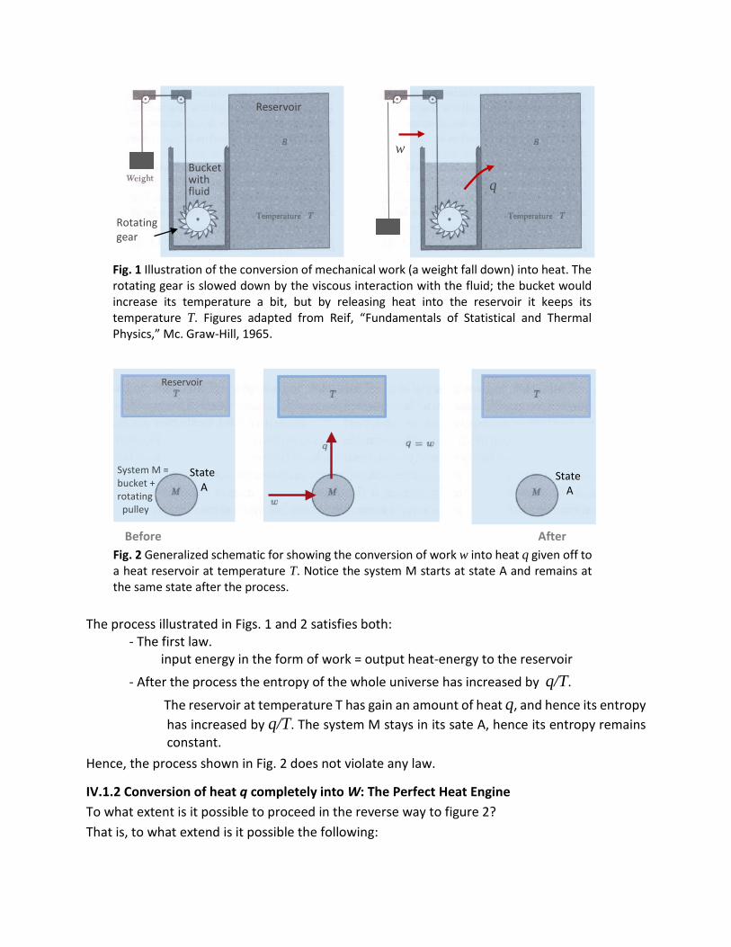
Reservoir
Bucket with fluid
Rotating gear
w
q
Fig. 1 Illustration of the conversion of mechanical work (a weight fall down) into heat. The rotating gear is slowed down by the viscous interaction with the fluid; the bucket would increase its temperature a bit, but by releasing heat into the reservoir it keeps its temperature T. Figures adapted from Reif, “Fundamentals of Statistical and Thermal Physics,” Mc. Graw-Hill, 1965.
Reservoir
System M = bucket + rotating pulley
State A
State A
Before After
Fig. 2 Generalized schematic for showing the conversion of work w into heat q given off to a heat reservoir at temperature T. Notice the system M starts at state A and remains at the same state after the process.
The process illustrated in Figs. 1 and 2 satisfies both: - The first law. input energy in the form of work = output heat-energy to the reservoir
- After the process the entropy of the whole universe has increased by q/T.
The reservoir at temperature T has gain an amount of heat q, and hence its entropy has increased by q/T. The system M stays in its sate A, hence its entropy remains constant.
Hence, the process shown in Fig. 2 does not violate any law.
IV.1.2 Conversion of heat q completely into W: The Perfect Heat Engine To what extent is it possible to proceed in the reverse way to figure 2? That is, to what extend is it possible the following:

i) to extract a net amount of energy from one reservoir (where that energy is randomly distributed over many degrees of freedom), and
ii) to transform it into work-energy associated a single degree of freedom motion (connected with the external parameter) of an outside device?
Figure 3 shows the prototype of the most desirable type of engine.
State A
State A
State A
Before After
Fig 3. Perfect engine. Upon completion of one cycle, the net result is that the system returns to its initial state-A and the net result is that heat-energy is fully converted to mechanical work.
The process illustrated in Fig. 3: - satisfies the first law: input heat-energy from the reservoir = output energy in the form of work - after the process the entropy of the whole universe has decreased by q/T . (This is a
violation of the second law expressed in (1).)
So the principle of increasing entropy of the universe is violated by the perfect engine outlined in Fig. 3. In other words:
It is impossible to construct a perfect heat engine. (3) (one that convert heat completely into work in a cyclic process.)
IV.1.3 Real Heat Engine (the need of a second heat reservoir at different temperature) What characteristic, then, has a real heat engine? How to modify the process outlined in Fig. 3 so that the principle of increasing entropy is no violated? When converting heat into work, what changes should we make so the entropy change of the universe becomes positive?
Solution: What about if only part of the heat energy q (from the reservoir at temperature Thigh) is converted into work w, and the remaining amount of heat (q-w) is given off to a reservoir of lower temperature Tlow?

If Tlow is low enough, the increase in entropy (q-w)/Tlow may be high enough to compensate or exceed the entropy q/Thigh lost by the other reservoir? Thus, while the universe losses entropy in the amount q/Thigh (at the reservoir of higher temperature Thigh) it gains entropy by depositing (q-w) / Tlow into the lower temperature heat reservoir. The second law makes the following requirement,
−𝑞𝑞 𝑇𝑇ℎ𝑖𝑖𝑖𝑖ℎ
+ 𝑞𝑞−𝑤𝑤 𝑇𝑇𝑐𝑐𝑜𝑜𝑙𝑙
≥ 0 (4)
T
Tlow
w
q
q- w
T
Tlow
Before After
T
Tlow
State A
State A
Fig 4. A scheme working at a single temperature does not allow to convert heat q fully into work w (w cannot be equal to q). The cyclic scheme above displays an alternative procedure involving instead two transfers of energy stages performed at two different temperatures, and where the system returns to its initial state. The new scheme fulfills the second law of thermodynamics and is able to deliver a net useful work, although w < q (where q is the heat supplied by the reservoir at high temperature.
For two selected temperatures T and Tlow, expression (4) then places a limitation on the maximum work possible to be attained from a heat machine,
w ≤ q ( 1 - 𝑇𝑇𝑐𝑐𝑜𝑜𝑙𝑙𝑇𝑇ℎ𝑖𝑖𝑖𝑖ℎ
) (5)
If we define the efficiency η of a heat engine by,
η ≡ work performed
heat energy needed
= 𝑤𝑤 𝑞𝑞
Efficiency of the heat-engine (6)
Expression (5) indicates that the efficiency of a heat engine is limited,
η ≤ ( 1 - 𝑇𝑇𝑐𝑐𝑜𝑜𝑙𝑙𝑇𝑇ℎ𝑖𝑖𝑖𝑖ℎ
) (7)
Given temperatures working temperatures T and Tlow, the machine of optimum efficiency will be the one that has an efficiency equal to,

ηmax = �1 − 𝑇𝑇𝑐𝑐𝑜𝑜𝑙𝑙𝑇𝑇ℎ𝑖𝑖𝑖𝑖ℎ
� < 1 (8)
Expressions (7) and (8) result from the second law requirement that the entropy of the universe should increase. IV.2 A different way to express the second law
We know that if we do work against friction, the work lost to us is equal to the heat produced. If we do such a work at room at temperature T (and we do the work slowly enough such that the room temperature does not change much) and we would have converted work into heat at a given single temperature.
Work Heat This is OK (9) Single degree multiple degrees of freedom of freedom
What about the reverse process? Is it possible to convert heat (from the multiple internal microscopic degrees of freedom constituting the internal energy of the room) system back into work at a given temperature?
Heat Work (?) (10) Multiple degrees (?) Single degree of freedom of freedom
If we considered only the conservation of energy, we could conceive that disordered heat energy (such as that contained in the vibrational motions of molecules) might provide a good supply of useful energy to do mechanical work (to lift weights, for example.) However, Carnot (the French Engineer who was the first to examine theoretically the operation of heat engines) asserts that the process (10) is not possible. More specifically,
Heat cannot be taken in at a certain temperature and be fully converted into (11) work with no other change in the system or the surroundings.
That last phrase is very important. If we do not inforce that request, we could visualize situations in which heat is fully converted into work.
For example, suppose we have a can of compressed air at a certain temperature T, and we let the air expand (see Fig. 5). In doing so the air system does work. The air cools off a little in the expansion, but if the air system is in contact with a heat reservoir at temperature T then the air warms it up again. So we have taken the heat q out of the reservoir, and it has been fully converted into useful work. Is expression (11) wrong, then? No, because we did not leave everything as it was. To place everything back one has to recompress the air. The compression at the same temperature will actually require doing extra work on the air. It turns out, when we are finished with the expansion and compression at the same temperature, we will discover that we not only got no work out of the system at temperature T, but we actually put some in.

So, working at a single temperature, no net work is obtained in a cyclic process.
Fext
Pi , Vi
T
Pf , Vf
T
Volume
Wsyst > 0
Pressure i
f
P1
P2
q > 0 (Heat absorbed by the system from the surroundings)
Wsyst > 0 (Work done by the system.)
Wsyst = q
Fig. 5 Air under a reversible iso-thermal expansion at temperature T. The heat q absorbed
from the walls is completely converted into useful work Wsyst. However, this does not contradicts statement (3). The comparison between the work done and the heat received has to be evaluated with the system and surroundings have returned to their initial states, which is not fulfilled in the case shown by the figure. To apply (3) one has to implement the compression of the gas back to its initial state.
Let’s emphasize that we must talk only about situations in which the net result of one cycle process is to take heat away and convert it into work. The clever assumption made by Carnot, who did not used the first law of thermodynamics, was that it is impossible to extract heat at a single temperature and convert it completely into work, with no other change in the system or the surroundings. In other words, if the whole world were at the same temperature, one could not convert any of its heat energy into work in a cyclic way (putting everything back to the same state after each cycle.)
Figures 6 and 7 shows another example to illustrate the principle stated in (11). In Fig. 6 the expansion of the gas does do work against the friction force, hence generating a given amount of heat. So work is fully converted into heat.
Friction Pi , Vi
T
Pf , Vf
T
Friction q
Fig. 6 Gas under expansion does work against the friction force. The work done is converted into heat that is transferred to the surroundings at temperature T.
Is the reverse process possible? Can heat spontaneously leave from the surroundings and do work against the gas (see Fig. 7)? According to Carnot: no!, that this is impossible.

Pi , Vi T
Pf , Vf
T
q Fig. 7 If the temperature of the surroundings is kept the same, spontaneous conversion of heat (from the surroundings) into useful work to compress the gas is not possible, according to Carnot.
This is why:
Pi , Vi
q Tlow
Pf , Vf
Tlow
q (postulated spontaneous heat transfer)
b) a)
Pi , Vi
Tlow
Refrigerator
Thigh
Tlow
Pf , Vf
q (due to isothermal expansion)
Tlow
Refrigerator
Thigh
Tlow
qR
c) d)
Fig. 8 a) to b): Heat from the Tlow-reservoir is converted into work to spontaneously compress the gas. The gas will heat up but, since it is in contact with the container maintained at constant temperature, heat will flow out back to the reservoir. Net flow of heat is zero; there is just net spontaneous compression of the gas. c) to d): The piston is connected to a refrigerator. During the expansion heat is absorbed from the Tlow reservoir, and the work is used to operate a refrigerator (which pumps additional heat qR from the low temperature reservoir to a higher temperature Thigh reservoir. The net a) to d) result is spontaneous flow of heat from the Tlow reservoir to the Thigh reservoir. But we know heat never flows spontaneously from a cold plate to a hot plate.
Fig. 8 a) to b) shows in more detail what would happen: Spontaneously, an amount of heat q
is extracted from the walls at temperature Tlow and used to do work to compress the gas. A compressed gas would heat up; but its contact with the walls at Tlow make an amount of heat q to flow back to the cold reservoir. In short, one get a gas self-compressed, and no net heat flow from the reservoir. From this stage we have two options:
• We attach the piston to the lever of an external machine to do work.

Indeed, allowing the gas to expand isothermically, the gas extract heat from the reservoir and do work on an external device. Thus, without any energy investment, we would have a machine that cools a reservoir at temperature Tlow and in addition we get work for free. That is not observed experimentally. The external machine alluded above could be a refrigerator (a machine that upon receiving work, it transports heat from a cold reservoir to a hot reservoir (see Fig. 8 c) to d). Therefore in a cycle (heat from the reservoir used to compress the gas, followed by an expansion while doing work on a refrigerator) the net effect is: pumping heat from a lower temperature reservoir to a higher temperature reservoir. That is, we would have a system that spontaneously pump heat from a lower temperature reservoir to a higher temperature reservoir. That is not observed experimentally.
IV.3 Universal Properties of Reversible Heat Engines
The next logical question is how to practically implement the strategy displayed in Fig. 4 above, for which expression (8) predicts a given maximum efficiency. It is of interest to show explicitly how such an engine of maximum efficiency ηmax, operating between two heat reservoirs, could be constructed. We will do that. But we will do it following a historic trend. That is, we will not take expression (1) (the one stating that the entropy of the universe increases in every process), but instead we will assume valid the statement expressed in (11), which forces us to explore heat-engines working at two temperature levels instead of just one.
The early work in thermodynamics was indeed very concerned with the operation and efficiency of devices for converting heat into useful work. An important technical problem of the time was the design of steam engines.
How much work can be extracted from a kilo of coal? Can the efficiency be improved by different temperatures or pressures, a different working substance than water; or some different mode of operation than pistons and cylinders? 1
Carnot (the French Engineer who was the first to examine theoretically the operation of heat engines) conceived a very simple heat-engine, which now bears his name. At the time, the second law was not established yet. Hence, it results interesting to follow a logic analysis that leads to the principle of “increase entropy of the universe”, as we know it now.
First, we will analyze the operation of heat-engines operating at two temperatures; i.e. we will assume from the beginning, as Carnot did, that cyclic conversion of heat (from the surroundings at single temperature T) into useful work to compress the gas is not possible. We will also use in the analysis the First Law of conservation of energy. (It is worth mentioning that the First Law was unknown at Carnot’s time, which illustrate the cleverness of Carnot thinking and to figure out how to arrive to the Second Law.) Second, ideal reversible heat-engines will be considered and demonstrate that they offer the maximum efficiency. At this point, some degree
1 E. T. Jaynes THE EVOLUTION OF CARNOT'S PRINCIPLE; EMBO Workshop on Maximum-Entropy Methods, Orsay, France, April 24-28, 1984.

of universality will start to be established, since it will be demonstrated that all type of reversible heat-engine (no matter how it is constructed) have the same maximum efficiency.
The third step consists in quantifying such a universal efficiency value; i.e. how nature dictates the limitations of a heat engine. Two views will be offered. i) The first describes the Carnot engine, which consists of reversible heat-exchanges and reversible-work interactions between an ideal gas system and its surroundings. This specific machine allows then to calculate explicitly its max efficiency, which (according to the demonstration given in the second step) should be a universal value. ii) An alternative view is presented by Feynman, in which, instead of using an engine made out of specific substance to build up his arguments, he rather uses purely logical argument to find out the law by which nature limits the efficiency of a heat-engine, alluding no particular substance at all. This second view includes the definition of an absolute temperature scale, the thermodynamic temperature scale. The procedure allows to identify the center of the universe of thermodynamics: the interchange of the quantity Q/T during thermal interaction with the two reservoirs within a reversible process. The quantity Q/T, we will realize, is then of paramount importance.
IV.3.1 Carnot analysis of heat-engines Carnot’s analysis of heat engines is quite similar to the argument given about weight-lifting
engines in the discussion of the conservation of energy in Lecture 7 The FIRST LAW of THERMODYNAMICS Section 1.2.B. In fact, that argument was patterned after Carnot’s argument about heat engines, and so the present treatment will sound very much the same.
Suppose we build a heat engine that has a “boiler” somewhere at a temperature Th. A certain heat Qh is taken from the boiler, the steam engine does some work W, and it then delivers some heat Qc into a “condenser” at another temperature Tc (Fig. 9). Carnot did not say how much heat, because he did not know the first law, and he did not use the law that Qh was equal to Qc because he did not believe it. Although everybody thought that, according to the caloric theory, the heats Qh and Qc would have to be the same, Carnot did not say they were the same—that is part of the cleverness of his argument.
Th
Tc
W
Qh
Qc
Heat engine
Fig. 9 Heat engine.
If we do use the first law, we find that the heat delivered, Qc, is the heat Qh that was put in minus the work W that was done:

Qc = Qh − W (12)
(If we have some kind of cyclic process where water is pumped back into the boiler after it is condensed, we will say that we have heat Qh absorbed and work W done, during each cycle, for a certain amount of water that goes around the cycle.)
We will analyze first an idealized optimum engine (one with no mechanical friction at least). Subsequently we will consider building another engine, and see if we can get more work (than from the idealized one) from the same amount of heat being absorbed from the reservoir at the temperature Th, and with the condenser still at the temperature Tc. We shall use the same amount of heat Qh from the boiler, and we shall try to get more work than we did out of the steam engine, perhaps by using another fluid, such as alcohol.
Idealized engine in which all the processes are reversible: The Carnot Engine Carnot had the happy idea of considering a reversible engine: One like the one in Fig. 9 above
but with the particular characteristic that one can turn the shaft backwards, delivering the same work W back to the engine, which then delivers the same heat Qh back to the high-temperature reservoir. To show that such a thing is possible in principle, we will give a specific example of an engine cycle which may or may not be practical, but which is at least reversible, in the sense of Carnot’s idea. Suppose that we have a gas in a cylinder equipped with a frictionless piston. The gas is not necessarily a perfect gas. The fluid does not even have to be a gas, but to be specific let us say we do have a perfect gas. Consider also two heat reservoir pads—great big things that have definite temperatures—of temperatures Th and Tc (Th > Tc.) A reversible thermal process would proceed as follows
We let the gas expand while in contact with the heat pad at Th. We do this by pulling the piston out very slowly as the heat flows into the gas, we will make sure that the temperature of the gas never gets very far from Th. If we pull the piston out too fast, the temperature of the gas will fall too much below Th and then the process will not be quite reversible; but if we pull it out slowly enough, the temperature of the gas will never depart much from Th. On the other hand, if we push the piston back slowly, the temperature would be only infinitesimally higher than Th, and the heat would pour back. We see that such an isothermal (constant-temperature) expansion, done slowly and gently enough, is a reversible process.
The pressure of the gas against its volume diagram in Fig. 10 illustrates better the full cycle process of the reversible Carnot engine.

(1)
(2) (3)
(4)
a
b
c
d
T= Th
T= Tc
Qh
Qc
Fig. 10 The Carnot Cycle. For the purpose of section IV.4.2, where a scale of absolute
temperature is defined, it is worth to highlight the following: a higher Qc (obtained by making Vd –Vc larger) implies a higher Qh; also, if a higher Th were selected, then a higher Qh will result. Hence, Qh increases monotonically with Qc and Th.
• Forward abcda cycle
The curve marked (1) in Fig. 10 tells us how the pressure and volume change if the temperature is kept fixed at the value Th. For an ideal gas this curve would be PV=NkT1. During an isothermal expansion the pressure falls as the volume increases until we stop at the point b. At the same time, a certain heat Qh must flow into the gas from the reservoir, for if the gas were expanded without being in contact with the reservoir it would cool off. The isothermal expansion stops at the point b.
Let us take the cylinder away from the reservoir and continue the expansion. This time we permit no heat to enter the cylinder. Again we perform the expansion slowly, so there is no reason why we cannot reverse it, and we again assume there is no friction. The gas continues to expand and the temperature falls, since there is no longer any heat entering the cylinder. The gas expand, following the curve marked (2), until the temperature falls to Tc at the point marked c. This kind of expansion, made without adding heat, is called an adiabatic expansion. For an ideal gas, we already know that curve (2) has the form PVγ =constant, where γ is a constant greater than 1, so that the adiabatic curve has a more negative slope than the isothermal curve. The gas cylinder has now reached the temperature Tc, so that if we put it on the heat pad at temperature Tc there will be no irreversible changes.
Now we slowly compress the gas while it is in contact with the reservoir at Tc, following the curve marked (3) in Fig. 10. Because the cylinder is in contact with the reservoir, the

temperature does not rise, but heat Qc flows from the cylinder into the reservoir at the temperature Tc. The gas is compressed isothermally along curve (3) to the point d.
We remove the cylinder from the heat pad at temperature Tc and compress it still further, without letting any heat flow out. The temperature will rise, and the pressure will follow the curve marked (4).
If we carry out each step properly, we can return to the point a at temperature Th where we started, and repeat the cycle.
Notice, in a PV diagram the area under each of the numbered curves is a measure of the work done by or on the gas in the corresponding step. Accordingly, the net work done Wrev is the shaded area of the picture.
The forward cycle can also be represented schematically as follows,
Th
Tc
State A
Th
Tc
Wrev
Qh
Qc
Heat engine
Th
Tc
State A
Fig. 11 Cyclic reversible process, representing the forward cycle abcda Carnot process of Fig. 8.
• Backward adcba cycle We see that on this diagram we have carried the gas around a complete cycle, and during one cycle we have put QH in at temperature TH, and have removed QC at temperature TC. Now the point is that this cycle is reversible, so that we could represent all the steps the other way around. We could have gone backwards instead of forwards: we could have started at point a, at temperature TH, expanded along the curve (4), expanded further at the temperature TC, absorbing heat QC, and so on, going around the cycle backward. IN this case we do a net work on the gas. This constitutes a refrigerator. The idea of refrigerator engine is to accomplish the unnatural heat transfer from a cold reservoir to a hot reservoir. The refrigerator engine will work in a cycle so that the change in the internal energy of the gas system around each cycle is zero (the system returns to its initial state-A.

Th
Tc
State A
Th
Tc
Wrev
Qh
Qc
Refrigerator engine
Th
Tc
State A
Fig. 12 Diagram representing the backward cycle adcba Carnot process of Fig. 10. This is the working principle of a refrigerator.
IV.3.2 Comparison between heat engines: No engine can do more work than a reversible one Now that we have given a single example of a reversible machine, let’s compare it with other
heat-engines.
Th
Tc
Wrev
Qh
Qc
A
Th
W ′
Qh′ =Qh
Qc′
B Tc
Fig. 13 Comparison between two heat engines. Heat engine A is reversible; out of heat Qh the engine delivers useful work in the amount of Wrev. Heat-engine B is any other heat-engine (reversible or not); out of heat Qh it deliver useful work in the amount of W’. Inside the text it is demonstrated that W’ cannot be greater than Wrev.
Let us assume that we have a reversible engine-A which takes QH at TH, does work Wrev, and delivers some heat at Tc (Fig. 13). Consider any other engine B, made by man, already designed or not yet invented, made of rubber bands, steam, or whatever, reversible or not, which is designed so that it takes-in the same amount of heat Qh at Th, does work W′, and rejects the heat at the lower temperature Tc . Now we shall show that W ′ is not greater than Wrev. That is, that no engine can do more work than a reversible one.

Th
Tc
Qh Qh
Qh - Wrev Qh - W ′
Wrev W ′ - Wrev A
B
Fig. 14 Reversible heat-engine A working in tandem with another heat engine. Notice, there is a net amount of heat (Qh – Wrev) – (Qh – W ′ ) = W ′ – Wrev leaving the reservoir at Tc and fully converted into useful work.
Suppose that, indeed, W ′ were bigger than Wrev. Let’s put engines A and B work in tandem as shown in Fig. 14.
We take heat Qh out of the reservoir at Th, and with engine B we do work W ′ (as indicated in Fig. 13 as well) and deliver some heat to the reservoir at Tc; we do not care how much. • We split the work W′ done by engine-B into Wrev and (W ′− Wrev):
i) The work Wrev is used to run engine-A backwards (we can do that because engine-A is reversible; this is the key aspect of the demonstration.) Engine-A will absorb some heat from the reservoir at Tc and deliver Qh back to the reservoir at Th.
ii) The remainder (W ′− Wrev) is saved for useful work.
In Fig. 14, the heat absorbed by engine–A from the reservoir at Tc is as indicated to fulfill the first law. Similarly for the heat delivered to the reservoir at Tc by engine-B. It turns out, • iii) A net amount of heat [ (Qh – Wrev) – (Qh – W ′ ) ] = W ′ – Wrev leaves the Tc reservoir.
Notice also that by purpose design, no net heat is placed into the reservoir at Th. After this double cycle we have put the Th reservoir and the two engines back the way they were before. The net result obtained from the A+B machine, emphasized in steps ii) and iii) above, is:
Extraction of a net amount of heat W′ – Wrev from the reservoir at Tc and its full conversion into work (see Fig. 15).

Th
W = (W ′ – Wrev )
Q = (W ′ – Wrev )
A+B
Tc
Fig. 15 Net result of the combined A+B machine outlined in Fig. 14 above. Full conversion of heat at a single temperature into work. This goes against the principle stated in (11).
But to obtain useful work from a reservoir at a single temperature with no other changes is impossible, according the principle state in (11).2 The assumption that W ′ > W rev is therefore wrong.
Therefore, no engine which absorbs a given amount of heat from a higher temperature Th and delivers it at the lower temperature Tc (13) can do more work than a reversible engine operating under the same temperature conditions. This is known as the Carnot’s principle
IV.3.3 Universality: Work perform by a reversible heat-engine
Now suppose that engine B is also reversible. Then, of course, not only must W′ = Wrev,B be not greater than Wrev,A, but now we can reverse the argument and show that Wrev,A cannot be greater than W′= Wrev,B. So, if both engines are reversible they must both do the same amount of work, and we thus come to Carnot’s brilliant conclusion:
If an engine is reversible, it makes no difference how it is designed, because the amount of work one will obtain if the engine absorbs a given amount of heat at temperature Th and delivers heat at some (14) other temperature Tc does not depend on the design of the engine. It is a property of the world, not a property of a particular engine.
Thus, the reversible efficiency 𝜖𝜖rev is a universal function of the two temperatures; 𝜖𝜖rev(T1, T2). Carnot's principle answered in one stroke all those questions, at the time, about improvements in steam engines. It resolved a mass of ambiguities. 2 This is similar to the situation addressed in Fig. 8 above. The excess W’- Wrev can be used not only to drive a refrigerator, but also ships, trains, cranes. Once started, the machine A+B would run forever, delivering an infinite amount of useful work by extracting heat, and hence, cooling a heat-reservoir. We would have a new kind of perpetual motion machine: Investing nothing, it delivers work at the expense of extracting heat from, for example, the sea.

“Carnot's reasoning is outstandingly beautiful, because it deduces so much from so little - and with such a sweeping generality that rises above all tedious details - but at the same time with such a compelling logical force. In this respect, Carnot's principle ranks with Einstein's principle of relativity.” 3 So we see that a substance’s properties must be limited in a certain way; we cannot make up anything we want. We cannot produce more than the maximum allowable work when we carried it around a reversible cycle. This principle, this limitation expressed in (14), is the only real rule that comes out of the thermodynamics.
But Carnot solved the problem only implicitly; while he made it clear that one should strive to make an engine more nearly reversible, he did not find the explicit formula for the reversible efficiency that would result.
𝜖𝜖rev(Th, Tc) = ? If we could find out the law is that determines how much work we obtain when we absorb the heat Qh at Th and deliver heat at Tc, this quantity would be a universal thing, independent of the substance. The universal character of 𝜖𝜖rev gives us a clue:
If we knew the properties of a particular substance, we could work it out and then say that all other substances must give the same amount of work in a reversible engine.
That is the key idea. That is the clue by which we can find the relationship between how much, for instance, a rubber band contracts when we heat it, and how much it cools when we let it contract. Imagine that we put that rubber band in a reversible machine, and that we make it go around a reversible cycle. The net result, the total amount of work done, is that universal function; the total work is that great function which is independent of substance. We figure out 𝜖𝜖rev(Th, Tc) in the next section. IV.4 What is the law that determines how much work we obtain from a reversible heat-
engine? The next important step is to find the universal law that determines the work W as a function
of Qh, Th, and Tc. We will follow two methods: i) We find 𝜖𝜖rev(T1, T2) by studying a reversible engine that uses a specific particular substance
whose laws we know, a perfect gas. ii) It is also possible “to obtain the rule by a purely logical argument, using no particular substance
at all. This is one of the very beautiful pieces of reasoning in physics and we are reluctant not to show it to you.” Feynman.
3 E. T. Jaynes THE EVOLUTION OF CARNOT'S PRINCIPLE; EMBO Workshop on Maximum-Entropy Methods, Orsay, France, April 24-28, 1984.

IV.4.1 Using a Carnot engine operating with an ideal-gas to figure out the law that determines how much work we can obtain from a reversible heat-engine?
In this section we describe the much less abstract and simpler method, which uses a perfect gas. We need to obtain only formulas for Qh and Qc (for W is just Qh − Qc).
How much heat Qh is absorbed from the reservoir at temperature Th during the isothermal expansion [marked (1) in Fig. 8] from point a (at pressure Pa, volume Va, temperature Th) to point b (at pressure Pb, volume Vb, and the same temperature Th)? For a perfect gas each molecule has an energy that depends only on the temperature, and since the temperature and the number of molecules are the same at a and at b, the internal energy is the same. There is no change in U. That means, during the expansion all the work W done by the gas, is energy Qh taken from the reservoir,
Qh = Wexpansion For a reversible thermal expansion For an ideal gas PV=Nk Th. Hence, the work during the expansion is equal to,
Wexpansion = ∫ 𝑃𝑃 𝑑𝑑𝑑𝑑𝑏𝑏𝑎𝑎
= ∫ 𝑁𝑁𝑁𝑁𝑇𝑇ℎ
𝑉𝑉 𝑑𝑑𝑑𝑑𝑏𝑏
𝑎𝑎
= 𝑁𝑁𝑁𝑁𝑇𝑇ℎln �𝑉𝑉𝑏𝑏𝑉𝑉𝑎𝑎�
Hence, 𝑄𝑄ℎ = 𝑁𝑁𝑁𝑁𝑇𝑇ℎln �𝑉𝑉𝑏𝑏
𝑉𝑉𝑎𝑎� Heat taken from the reservoir at Th. (15)
In the same way, for the compression at Tc [curve (3) of Fig. 8] the heat delivered to the reservoir at Tc is, 𝑄𝑄𝑐𝑐 = 𝑁𝑁𝑁𝑁𝑇𝑇𝑐𝑐ln �𝑉𝑉𝑐𝑐
𝑉𝑉𝑐𝑐� Heat delivered to the reservoir at Tc. (16)
Let’s find now a relationship between the volumes Va, Vb, Vc, Vd. This is done by noticing that in the adiabatic expansion from b to c [curve (2) in Fig. 8] PVγ is a constant.
(PV)Vγ−1 is a constant.
Since for an ideal gas PV = NkT, we can write this as,
(NkT)Vγ−1 is a constant.
Hence, the adiabatic expansion from b to c satisfies,
(NkTh)(Vb)γ−1 = (NkTc)(Vc)γ−1
Similarly, during the adiabatic compression from d to a, (NkTh)(Va)γ−1 = (NkTc)(Vd)γ−1
The last two expressions give,

Vb / Va = Vc / Vd (17)
From (15), (16), and (17), we obtain,
𝑄𝑄ℎ𝑇𝑇ℎ
= 𝑄𝑄𝑐𝑐𝑇𝑇𝑐𝑐
(18)
This is the relation we were seeking. Although proved for a perfect gas engine, we know it must be true for any reversible engine.
In general, the efficiency of a heat engine is given by 𝜖𝜖 = (1 - 𝑄𝑄𝑐𝑐𝑄𝑄ℎ
). For a reversible heat engine
expression (18) gives,
𝜖𝜖rev (Th, Tc) = (1 - 𝑇𝑇𝑐𝑐𝑇𝑇ℎ
) (19)
IV.4.2 A more general derivation of the law that determines the work done by a reversible engine
Now we shall see how this universal law (19) could also be obtained by logical argument, without knowing the properties of any specific substances. Suppose that we have three engines and three temperatures, let us say t1 > t2 > t3. The temperature scale t is basically arbitrary (the uniformly spaced marks on a mercury thermometer, for example.)
A
B
t1
t3
t2
t1
C
t2
Fig. 16 Engines A and B together are equivalent to engine-C. They absorb the same amount of heat from the t1 reservoir, deliver the same amount of heat to the t2 reservoir, and both do the same amount of work.
• Let engine-A absorb heat Q1 from the temperature t1, do a certain amount of work W13, and
let it deliver heat Q3 to the temperature t 3 (Fig. 14).

Let engine-B run backwards between t2 and t3. Suppose that we let this second engine be of such a size that it will absorb the same heat Q3, and deliver the heat Q2. We will have to put a certain amount of work W32, into it—negative because the engine is running backwards. When the machine-A goes through a cycle, it absorbs heat Q1 and delivers Q3 at the temperature t3; then machine-B takes the same heat Q3 out of the reservoir at the temperature t3 and delivers Q2 into the reservoir at temperature T2.
Therefore the net result of the two macnes A and B in tandem is to take heat Q1 from t1, deliver Q2 at t2, and do work W13 - W32.
• Are the two machines A and B working together equivalent to a third one (engine-C) that absorbs Q1 at t1, and delivers heat Q2 into the reservoir at temperature t2?
• To answer this question, let’s compare the work done by (A+B) and C: The tandem A+B does work equal to W13 - W32 = (Q1 – Q3) - (Q2 – Q3) = (Q1 – Q2). On the other hand, engine-C does work equal to W12 = (Q1 – Q2).
Therefore, engine (A+B) and engine-C, shown in Fig. 16, are equivalent.
We can now obtain the laws which relate the efficiencies of the engines, because there clearly must be some kind of relationship between the efficiencies of engines running between the temperatures t1 and t3, between t2 and t3, and between t1 and t2.
𝜖𝜖12 (t1 , t2) = 𝑊𝑊12𝑄𝑄1
𝜖𝜖23 (t2 , t3) = 𝑊𝑊23𝑄𝑄2
𝜖𝜖13(t1 , t3) = 𝑊𝑊13𝑄𝑄1
(20)
There must be a certain relationship between these efficiencies compatible with the fact that in Fig. 16 the machine A+B is equivalent to machine-C.
𝜖𝜖12 = 𝑊𝑊12𝑄𝑄1
= 𝑊𝑊13−𝑊𝑊23𝑄𝑄1
= 𝜖𝜖13 − 𝑊𝑊23𝑄𝑄1
= 𝜖𝜖13 − 𝜖𝜖23 𝑄𝑄2𝑄𝑄1
Using W12 = (Q1 – Q2).
= 𝜖𝜖13 − 𝜖𝜖23 𝑄𝑄1 − 𝑊𝑊12 𝑄𝑄1
= 𝜖𝜖13 − 𝜖𝜖23 ( 1 − 𝑊𝑊12 𝑄𝑄1
)
𝜖𝜖12 = 𝜖𝜖13 − 𝜖𝜖23 (1 − 𝜖𝜖12 )
𝜖𝜖12 + 𝜖𝜖23 (1 − 𝜖𝜖12 ) = 𝜖𝜖13

− 𝜖𝜖12 − 𝜖𝜖23 (1 − 𝜖𝜖12 ) = − 𝜖𝜖13
(1 − 𝜖𝜖12 ) − 𝜖𝜖23 (1 − 𝜖𝜖12 ) = (1 − 𝜖𝜖13)
(1 − 𝜖𝜖12 ) (1 − 𝜖𝜖23 ) = (1 − 𝜖𝜖13) (21)
Solution
(1 − 𝜖𝜖𝑖𝑖𝑖𝑖 ) = 𝑓𝑓(𝑡𝑡𝑗𝑗)
𝑓𝑓(𝑡𝑡𝑖𝑖) (22)
where f is a function to be determined Indeed, (22) fulfills (21),
𝑓𝑓(𝑡𝑡2)𝑓𝑓(𝑡𝑡1)
𝑓𝑓(𝑡𝑡3)𝑓𝑓(𝑡𝑡2)
= 𝑓𝑓(𝑡𝑡3)𝑓𝑓(𝑡𝑡1)
By Carnot's principle the ratio 𝑓𝑓(𝑡𝑡𝑗𝑗)
𝑓𝑓(𝑡𝑡𝑖𝑖) must be the same function of (ti, tj ) for all reversible
engines.
What about the function f? From the first and third expression of (20), together with (22),
𝜖𝜖12 (t1, t2) = 𝑊𝑊12𝑄𝑄1
= 1 - 𝑓𝑓(𝑡𝑡2)𝑓𝑓(𝑡𝑡1)
𝜖𝜖13(t1, t3) = 𝑊𝑊13𝑄𝑄1
= 𝑊𝑊12+𝑊𝑊23𝑄𝑄1
= 1 - 𝑓𝑓(𝑡𝑡3)𝑓𝑓(𝑡𝑡1)
where we notice that 𝑓𝑓(𝑡𝑡3) < 𝑓𝑓(𝑡𝑡2). That is, 𝑓𝑓(𝑡𝑡) increases monotonically with the temperature t (23)
The Thermodynamic Temperature scale: The Kelvin’s scale The temperature scale t used above is basically arbitrary; as such it is a troublesome problem
(the uniformly spaced marks on a mercury thermometer and on a gas thermometer, for example, do not agree). Turning the argument around, Kelvin perceived that Carnot's principle (the universal value of the efficiency) resolves also another ambiguity:
If the reversible efficiency (the left side of expression (22)) is a universal function of the temperatures, then its universal value can be used to define a universal temperature scale (right side of expression (22)) that is independent of the properties of any particular substance like mercury.
(In other words, we can use a heat-engine as a thermometer. We can do this by first measuring the efficiency of the reversible heat-engine (this is a universal value). Then we keep one of the two temperatures fixed (it will be a standard point temperature, whose numerical value Tstandard

can be assigned arbitrarily.) The other temperature will then be determined by the universal value of the engine’s efficiency. How? More details in the next section.)
Along these lines, the Kelvin’s absolute temperature scale is defined by,
T(t) = C f (t) (24)
where we may choose the arbitrary multiplicative factor C to indicate the size of the units in which we measure temperature. So f (t) is its self the absolute temperature From (22), Carnot's reversible efficiency is then,
𝜖𝜖𝑖𝑖𝑖𝑖 = 1 - 𝑇𝑇𝑗𝑗𝑇𝑇𝑖𝑖
(25)
All such thermometers, however constructed and independently calibrated, will then agree in their readings at all points, if the units are chosen so that they agree at one point (the arbitrarily chosen reference or standard point.) Since for any heat-engine wokring at temperatures Ti and Tj (with Ti > Tj ) the efficiency is given by,
𝜖𝜖 = �1 − 𝑄𝑄𝑗𝑗𝑄𝑄𝑖𝑖�
we have found that, in terms of the Kelvin temperature scale,
𝑄𝑄𝑗𝑗𝑄𝑄𝑖𝑖
= 𝑇𝑇𝑗𝑗𝑇𝑇𝑖𝑖
(26)
We arrive then to the following conclusion,
if a heat engine, running through a reversible process between T1 and T2, absorbs energy Q1 at temperature T1 and delivers heat Q2 at temperature T2,
then the heats follow this relationship,
𝑄𝑄1𝑇𝑇1
= 𝑄𝑄2𝑇𝑇2
This is the center of the universe of thermodynamics (27)
Given T1 and T2, for a given amount of heat Q1 investment into a heat-engine, (24) tell us how much is Q2 and, hence, we have figured out the work W (equal to Q1 – Q2) delivered by the reversible machine. We have figured out then how much useful work we can we get from a kilo of coal.
This is the grand finale of the whole analysis!
Just as F=ma is the center of the universe in mechanics, 𝑄𝑄1𝑇𝑇1
= 𝑄𝑄2𝑇𝑇2
is all there is to thermodynamics. We have figured out not only how much work can we
get from a kilo of coal, but we have found a particular quantity Q/T that acquires paramount
importance to describe the dynamics of macroscale multi-particles systems (as will be addressed below.)
Note: If we refer to all the heats involved as the “heats absorbed from” the reservoirs we would
re-write the new law as 𝑄𝑄1𝑇𝑇1
= − 𝑄𝑄2𝑇𝑇2
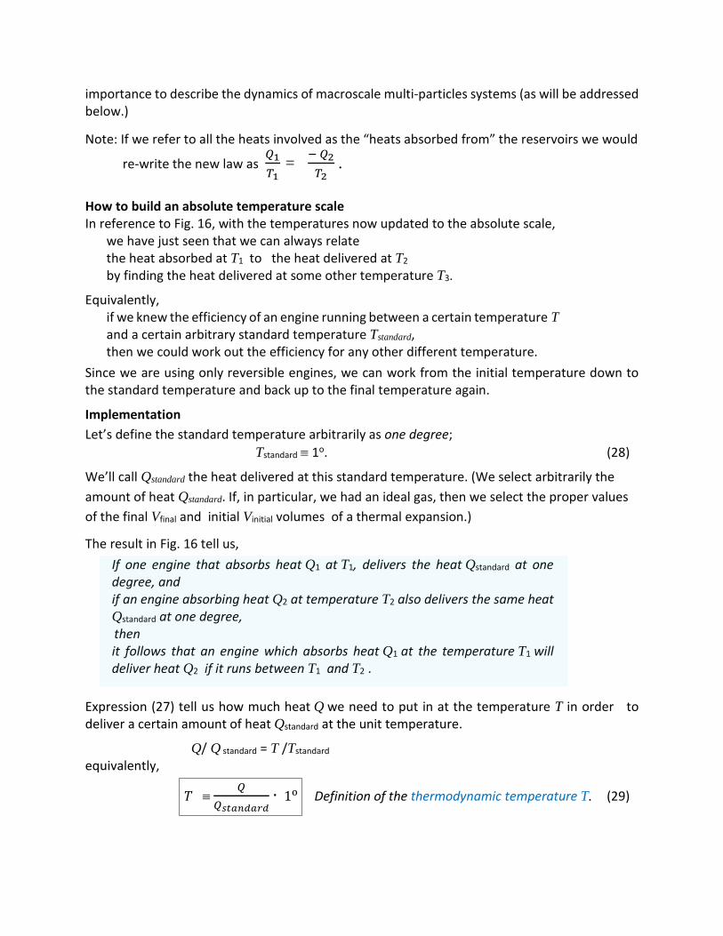
. How to build an absolute temperature scale In reference to Fig. 16, with the temperatures now updated to the absolute scale,
we have just seen that we can always relate the heat absorbed at T1 to the heat delivered at T2 by finding the heat delivered at some other temperature T3.
Equivalently, if we knew the efficiency of an engine running between a certain temperature T and a certain arbitrary standard temperature Tstandard, then we could work out the efficiency for any other different temperature.
Since we are using only reversible engines, we can work from the initial temperature down to the standard temperature and back up to the final temperature again.
Implementation Let’s define the standard temperature arbitrarily as one degree; Tstandard ≡ 1o. (28)
We’ll call Qstandard the heat delivered at this standard temperature. (We select arbitrarily the amount of heat Qstandard. If, in particular, we had an ideal gas, then we select the proper values of the final Vfinal and initial Vinitial volumes of a thermal expansion.)
The result in Fig. 16 tell us, If one engine that absorbs heat Q1 at T1, delivers the heat Qstandard at one degree, and if an engine absorbing heat Q2 at temperature T2 also delivers the same heat Qstandard at one degree,
then it follows that an engine which absorbs heat Q1 at the temperature T1 will deliver heat Q2 if it runs between T1 and T2 .
Expression (27) tell us how much heat Q we need to put in at the temperature T in order to deliver a certain amount of heat Qstandard at the unit temperature.
Q/ Q standard = T /Tstandard equivalently,
𝑇𝑇 ≡ 𝑄𝑄
𝑄𝑄𝑠𝑠𝑜𝑜𝑎𝑎𝑠𝑠𝑐𝑐𝑎𝑎𝑠𝑠𝑐𝑐∙ 1o Definition of the thermodynamic temperature T. (29)

This means that we can tell how hot an object is by measuring how much heat Q is absorbed by a reversible engine working between the temperature of the object and the unit temperature (see Fig. 17). If seven times more heat is taken out of a boiler than is delivered at a one-degree condenser, the temperature of the boiler will be called seven degrees, and so forth. So, by measuring how much heat is absorbed at different temperatures, we determine the temperature.
The temperature defined in this way is called the absolute thermodynamic temperature, and it is independent of the substance.
W = Q – Qstandard
Q
Qstandard
Experimentally measured
Experimentally measured
T defined in terms of the measured value of Q.
T = (Q / Qstandard) . 1o
10 Fig. 17 Heat engine as a thermometer. Now we see that when we have two engines,
one working between T1 and one degree, where 𝑄𝑄1𝑄𝑄𝑠𝑠𝑜𝑜𝑎𝑎𝑠𝑠𝑐𝑐𝑎𝑎𝑠𝑠𝑐𝑐
= 𝑇𝑇11o
,
and the other working between T2 and one degree, where 𝑄𝑄2𝑄𝑄𝑠𝑠𝑜𝑜𝑎𝑎𝑠𝑠𝑐𝑐𝑎𝑎𝑠𝑠𝑐𝑐
= 𝑇𝑇21o
,
that is, both delivering the same amount of heat 𝑄𝑄𝑠𝑠𝑡𝑡𝑎𝑎𝑠𝑠𝑠𝑠𝑎𝑎𝑠𝑠𝑠𝑠 at unit temperature, then
the heats absorbed must be related by,
𝑄𝑄1𝑇𝑇1
= 𝑄𝑄2𝑇𝑇2
Based on the analysis of three engines working together done above, this result implies that:
if a single engine, running through a reversible process between T1 and T2, absorbs energy Q1 at temperature T1 and delivers heat Q2 at temperature T2,
then the heats follow this relationship,

𝑄𝑄1𝑇𝑇1
= 𝑄𝑄2𝑇𝑇2
Consequences of the 𝑸𝑸𝟏𝟏𝑻𝑻𝟏𝟏
= 𝑸𝑸𝟐𝟐𝑻𝑻𝟐𝟐
law
• Combining both laws, the law of conservation of energy and the law that relates the heats Qc and Qh, one can obtain the efficiency of a reversible engine.
From the first law, we have W=Qh − Qc.
According to our new principle, 𝑄𝑄𝑐𝑐 = 𝑇𝑇𝑐𝑐𝑇𝑇ℎ
𝑄𝑄ℎ
So the work becomes,
W = Qh − 𝑇𝑇𝑐𝑐𝑇𝑇ℎ
𝑄𝑄ℎ
W = Qh �𝑇𝑇ℎ − 𝑇𝑇𝑐𝑐𝑇𝑇ℎ
�
Efficiency = 𝑊𝑊𝑄𝑄1
= �𝑇𝑇ℎ−𝑇𝑇𝑐𝑐𝑇𝑇ℎ� Efficiency of a reversible heat-engine (30)
Since 𝑇𝑇2 must be positive, the efficiency is always less than unity. That is the first consequence of the new law.
• In passing, the efficiency of a heat-engine is given by η ≡ work performed
heat energy needed =
𝑤𝑤 𝑞𝑞𝐻𝐻
=
= 𝑞𝑞ℎ− 𝑞𝑞𝑐𝑐
𝑞𝑞ℎ = 1 −
𝑞𝑞𝑐𝑐 𝑞𝑞ℎ
. We have just learned that it cannot exceed the efficiency 1 − 𝑇𝑇𝑐𝑐 𝑇𝑇ℎ
of a reversible engine; hence,
1 − 𝑞𝑞𝑐𝑐 𝑞𝑞ℎ
< 1 − 𝑇𝑇𝑐𝑐 𝑇𝑇ℎ
,
𝑞𝑞𝑐𝑐 𝑞𝑞ℎ
> 𝑇𝑇𝑐𝑐 𝑇𝑇ℎ
𝑞𝑞𝑐𝑐 𝑇𝑇𝑐𝑐
> 𝑞𝑞ℎ 𝑇𝑇ℎ
𝑞𝑞𝑐𝑐 𝑇𝑇𝑐𝑐
- 𝑞𝑞ℎ 𝑇𝑇ℎ
> 0 For non-reversible heat engine (31)

Th
Tc
State A
Th
Tc
w
qh
qc
Th
Tc
State A
Fig. 18 Reversible process produces the highest work, Wrev > W. For a fixed value of qh, a higher value of qc causes both a lower work w performed and a greater difference qc /Tc – qh
/Th. The minimum value possible for qc (that makes the work W higher) is the one that makes qc /Tc – qh /T h = 0; this latter occurs when the process is reversible.
IV.5 Entropy
Working always with reversible engines, equation 𝑄𝑄1𝑇𝑇1
= 𝑄𝑄2𝑇𝑇2
can be interpreted in a special way.
• Heat-transfer 𝑄𝑄1 at temperature 𝑇𝑇1 is “equivalent” to heat-transfer 𝑄𝑄2 at temperature 𝑇𝑇2
if 𝑄𝑄1𝑇𝑇1
= 𝑄𝑄2𝑇𝑇2
.
As one is absorbed the other is delivered.
• This suggests that if we call 𝑄𝑄𝑇𝑇
something, we can say:
in a reversible process as much 𝑄𝑄𝑇𝑇
is absorbed as it is liberated;
i.e. there is no gain or loss of 𝑄𝑄𝑇𝑇
.
𝑄𝑄𝑇𝑇
is called entropy change ∆S (32)
Accordingly, “there is no net change in entropy in a reversible cycle.” The entropy lost by one reservoir at T1 is gained by the other reservoir at T 2.
• If one of these two temperatures is the standard temperature 1∘, then,
𝑄𝑄𝑇𝑇
= ∆S = 𝑄𝑄𝑠𝑠𝑜𝑜𝑎𝑎𝑠𝑠𝑐𝑐𝑎𝑎𝑠𝑠𝑐𝑐
1𝑜𝑜 in a reversible cycle (33)
Q is the heat released by the reservoir at temperature T, and
Qstandard is the het delivered to the reservoir at temperature 1o.

For a non-reversible heat engine, we have found in the previous section above that in a cycled process
𝑞𝑞2 𝑇𝑇2
- 𝑞𝑞1 𝑇𝑇1
> 0 • The new interpretation of the quantity q/T tell us that,
𝑞𝑞2 𝑇𝑇2
is the entropy gained by the lower temperature reservoir.
𝑞𝑞1 𝑇𝑇1
is the entropy lost by the higher temperature reservoir
The difference � 𝑞𝑞2 𝑇𝑇2
− 𝑞𝑞1 𝑇𝑇1� is therefore the net entropy change of the
universe. Thus,
∆Suniverse > 0 For a non-reversible heat-engine (34)
Entropy as a state function It is interesting that in addition to the pressure P (which is a function of the temperature and the volume,) and the internal energy U (which is a function of temperature and volume,) we have found another quantity, the entropy of the substance S, which is a function of the condition. Let us try to explain how we compute it, and what we mean when we call it a “function of the condition.”
Consider a gas system in two different conditions (similar to as we had in the experiment where we did the adiabatic and isothermal gas expansions.) Incidentally, there could be three, four, or more different reservoirs at different temperatures at which a system takes in and/or delivers amounts of heat.) A gas system is moved around on a P-V diagram, going from one condition to another. • Consider the gas is in a certain condition a, and then it goes over to some other condition b.
We will require that this transition from a to b, to be reversible. • Now suppose that all along the path from a to b we have little reservoirs at different
temperatures, so that the heat (ẟQ)i removed from the substance at each little step-i is delivered to each reservoir at the temperature Ti corresponding to that point on the path.
• Then let us connect each of these reservoirs, by corresponding reversible heat engines, to a single reservoir at the unit temperature 1o.
• Notice, when we are finished carrying the substance from a to b, we would have brought all the reservoirs (the ones with different temperatures shown in the figure) back to their original condition. The net effect is that each amount of heat (ẟQ)i absorbed from the gas substance at temperature Ti has now been processed by a reversible machine, and, as a result, an amount of entropy (dS)i has been delivered to the unit temperature reservoir as follows. At each step-i we have:

(dS)i = (ẟ𝑄𝑄)𝑖𝑖𝑇𝑇𝑖𝑖
= (ẟ𝑄𝑄𝑠𝑠𝑜𝑜𝑎𝑎𝑠𝑠𝑐𝑐𝑎𝑎𝑠𝑠𝑐𝑐)𝑖𝑖
1o Gas-system’s change of entropy at step i.
(ẟQ)i
(ẟQ)i
(ẟQstanandard)i
Ti
1o 1o
Path undergone by the gas-system
Fig. 19 Change in entropy
The entropy needed to go from a to b along this particular reversible transformation is the total entropy delivered to the unit temperature reservoir:
Sb - Sa = ∑(ẟ𝑄𝑄)𝑖𝑖𝑇𝑇𝑖𝑖𝑖𝑖 = ∑
(ẟ𝑄𝑄𝑠𝑠𝑡𝑡𝑠𝑠𝑠𝑠𝑑𝑑𝑠𝑠𝑠𝑠𝑑𝑑)𝑖𝑖1𝑜𝑜𝑖𝑖
= ∫ ẟ𝑄𝑄𝑇𝑇
𝑏𝑏𝑎𝑎 =
11o
∫ ẟ𝑄𝑄𝑠𝑠𝑡𝑡𝑎𝑎𝑠𝑠𝑠𝑠𝑎𝑎𝑠𝑠𝑠𝑠𝑏𝑏𝑎𝑎
Sb - Sa = ∫ ẟ𝑄𝑄𝑇𝑇
𝑏𝑏𝑎𝑎 =
𝑄𝑄𝑠𝑠𝑜𝑜𝑎𝑎𝑠𝑠𝑐𝑐𝑎𝑎𝑠𝑠𝑐𝑐1o
Total entropy delivered to
the unit temperature reservoir
We will interpret ẟ𝑄𝑄 as the heart absorbed by the gas system from the little reservoirs (then the (ẟ𝑄𝑄)𝑖𝑖 for the particular case shown in the figure above are intrinsically negative.) Thus we state,
Sb - Sa = ∫ ẟ𝑄𝑄𝑇𝑇
𝑏𝑏𝑎𝑎 Entropy change in the reversible process a b (35)
ẟ𝑄𝑄 is the amount of hear absorbed by the system at each differential step
Does the entropy difference depend upon the path taken?

There is more than one way to go from a to b. In a Carnot cycle, for example, we could go from one state to another by first expanding isothermally and then adiabatically; or we could first expand adiabatically and then isothermally. So the question is whether the entropy change which occurs when we go from a to b in the Fig. 19 is the same on one route as it is on another. Answer: It must be the same. The reason is that if we went all the way around the cycle, going forward on one path and backward on another, we would have a reversible engine, and there would be no loss of heat to the reservoir at unit temperature. In a totally reversible cycle, no heat will be given to nor taken from the reservoir at the unit temperature, so the entropy needed to go from a to b is the same over one path as it is over another.
Sb - Sa is independent of path. It depends only on the endpoints.
We can, therefore, say that there is a certain function S=S (V, T), which we call the entropy of the substance, that depends only on the condition, i.e., only on the volume and temperature.
Total entropy change aba = 0
Fig. 20. Change in entropy in a completely reversible cycle aba. How specifically does the change in entropy depend on V and T?
The entropy difference Sb - Sa between two states a and b can be evaluated in different ways, through a reversible or irreversible process. But if done through a reversible one, it will be given in terms of the heat rejected at unit temperature, which happens to be given by,
S(Vb, Tb) - S(Va, Ta) = ∫ ẟ𝑄𝑄𝑇𝑇
𝑏𝑏𝑎𝑎 (36)
where ẟ𝑄𝑄 is the heat removed from the substance at temperature T.
Let us calculate the entropy of a perfect gas. How does S depend on T ?
Consider an isothermal (and therefore reversible) expansion. Since the temperature is constant, one obtains,
∆𝑆𝑆𝑔𝑔𝑎𝑎𝑠𝑠 = 1𝑇𝑇
∫ 𝑑𝑑𝑞𝑞𝑠𝑠𝑟𝑟𝑟𝑟𝑏𝑏𝑎𝑎 =
𝑞𝑞𝑠𝑠𝑟𝑟𝑟𝑟𝑇𝑇
(37)
For an ideal gas, the internal energy U depends only on the temperature U =32𝑁𝑁𝑁𝑁𝑇𝑇. So, in an
isothermal process the internal energy remains constant. The fist law establishes that, ∆U = qrev - Wrev = 0 qrev = Wrev (38)
In a reversible expansion, Wrev = ∫ 𝑃𝑃 𝑑𝑑𝑑𝑑𝑏𝑏
𝑠𝑠 = ∫ 𝑁𝑁𝑁𝑁𝑇𝑇𝑉𝑉
𝑏𝑏𝑎𝑎 𝑑𝑑𝑑𝑑 = 𝑁𝑁𝑁𝑁𝑇𝑇 ln (𝑉𝑉𝑏𝑏
𝑉𝑉𝑎𝑎) (39)
Replacing (38) and (39) in (37),
S(Vb, Tb) - S(Va, Ta) = 𝑁𝑁𝑁𝑁 ln (𝑉𝑉𝑏𝑏𝑉𝑉𝑎𝑎
) (40)
So, S(V, T) = 𝑁𝑁𝑁𝑁 ln (𝑑𝑑) plus some function of T only.
S(V, T) = 𝑁𝑁𝑁𝑁 ln (𝑑𝑑) + g(T) (41) How does S depend on T ?
Let’s consider a reversible adiabatic expansion; i.e. no heat is exchanged. Accordingly Δ𝑆𝑆 =0. From (41), ∆S = Δ(𝑁𝑁𝑁𝑁 ln (𝑑𝑑)) + Δ(𝑔𝑔(𝑇𝑇)) , g 𝑓𝑓(𝑇𝑇) = ? (42) In an adiabatic process TVγ−1=constant
ln(𝑇𝑇) + (𝜈𝜈 − 1) ln (𝑑𝑑) = const
ln (𝑑𝑑) = - 1(𝜈𝜈−1)
ln(𝑇𝑇) + const (43)
To obtain ∆S = 0 in (42), while fulfilling (43), 𝑓𝑓(𝑇𝑇) must be equal to
𝑓𝑓(𝑇𝑇) = 𝑁𝑁𝑁𝑁
(𝜈𝜈−1) ln(𝑇𝑇) + const
Hence,
S(V, T) = 𝑁𝑁𝑁𝑁 ln (𝑑𝑑) + 𝑁𝑁𝑁𝑁
(𝜈𝜈−1) ln(𝑇𝑇) + c (44)
where c is some constant independent of both V and T.

Refrigerator Engine The idea of refrigerator engine is to accomplish the unnatural heat transfer from a cold reservoir to a hot reservoir. The refrigerator engine will work in a cycle so that the change in the internal energy of the gas system around each cycle is zero (the system returns to its initial state-A.

Th
Tc
State A
Th
Tc
w
qh
qc
Refrigerator engine
Th
Tc
State A
Additional references: https://www.scientificamerican.com/article/battle-between-quantum-and-thermodynamic-
laws-heats-up/ https://blogs.scientificamerican.com/guest-blog/does-quantum-mechanics-flout-the-laws-of-
thermodynamics/ https://www.nature.com/articles/nature10123.epdf?referrer_access_token=qXurb8gScdzl9H
GMF0rMWdRgN0jAjWel9jnR3ZoTv0PLHpnSNGAsRKiXO4qPBDTP75_PbP5Egp-3xF7IXz5VMUKG1MOfguiI-7kxicAwNwjEFrodU9tO6LEcBAsUguqSDkQO_-58E71pUCRusx3NvwnNfB-zRedXJYQryDE1nYsepSJF1hTDjhMvpo46UXa_ZbDyfv5B71uDAoPGsX0__RQ_xxTh0SP8RfSdcK8uuOb-ACg5BP_KGUOIWNAnqV0I-LBtSfw7irir61q7tnqpXP6X6thylo1homMvHv4yTzU%3D&tracking_referrer=blogs.scientificamerican.com