com...the line differential relay. phase fault overcurrent protection grl150 provides three phase...
TRANSCRIPT

www . El
ectric
alPar
tMan
uals
. com

GRL150
2
FEATURES Applicable to two-ended feeders with fibre optic
or pilot wire communication Phase-segregated differential protection Integrated overcurrent guard scheme Direct intertripping Programmable control logic function Communication channel monitoring Built-in 5kV and optional 20kV isolation
transformer for pilot wire communication Four stage overcurrent protection for phase
and optional earth faults with IDMTL or DTL Four stage sensitive earth fault protection with
IDMTL or DTL (option) Programmable reset characteristics for first
stage OC, EF and SEF protection Inrush current detector for blocking differential
and/or overcurrent trip at energisation Undercurrent protection with DTL Thermal overload protection Broken conductor detection Circuit breaker fail protection Cold load pick-up feature CT supervision Four settings groups Configurable binary inputs and outputs Circuit breaker condition monitoring Trip circuit supervision Automatic self-supervision Menu-based HMI system Configurable LED indication Metering and recording functions Communications for remote setting and data
download is provided via the RSM (Relay Setting and Monitoring) system
Front mounted RS232 serial port for local PC communications
Rear mounted RS485 or fibre optic serial port for remote PC communications
Supports IEC 60870-5-103 protocol for communication with a substation control and monitoring system
APPLICATION The GRL150 is a range of fully numeric, multi-function, line differential protection relays from Toshiba. It provides fully numerical phase-segregated line differential protection for use with pilot wire or direct fibre optic communication. GRL150 has two models which differ according to the communication interface, see Table 1.
Table 1 – GRL150 Models
Model Configuration GRL150-100 Pilot wire applications GRL150-400 Pilot wire or direct F.O. application
Fig.1 Telecommunication system
Model 100 is for pilot wire applications. Model 400 provides both pilot wire and fibre optic interfaces and the type of communication applied is selectable by manual setting.
All models include multiple, high accuracy, phase-segregated protection elements with integrated overcurrent guard scheme and continuous channel supervision.
GRL150 system is a master/master design. Each terminal has a differential calculation function and performs arithmetical operation independently and simultaneously.
In addition, GRL150 provides back-up phase overcurrent protection with inverse time and definite time delay functions and optional earth or sensitive earth fault protection.
All models provide continuous monitoring of internal circuits and of software. External circuits are also monitored, by trip circuit supervision, CT supervision, and CB condition monitoring features.
A user-friendly HMI is provided through a backlit LCD, programmable LEDs, keypad and menu-based operating system. PC access is also provided, either for local connection via a front-mounted RS232 port, or for remote connection via a rear-mounted RS485 or fibre optic port. The communication system allows
b) GRL150-400 (pilot wire or fibre optic applications)
Direct fibre optic interface
a) GRL150-100 (Pilot wire applications)
GRL150
PW
Pilot wire interface (built-in 5kV isolation)
GRL150 PW
FO
87
87
Pilot wire (up to 8km with AWG19)
Fibre optic (up to 20km)
Pilot wire (up to 8km with AWG19)
www . El
ectric
alPar
tMan
uals
. com

GRL150
3
the user to read and modify the relay settings, and to access data gathered by the relay’s metering and recording functions.
Data available either via the relay HMI or communications ports includes the following functions.
Metering Fault recording Event recording Disturbance recording
FUNCTIONS
Phase-segregated Current Differential Protection GRL150 provides phase-segregated current differential protection for both phase to phase faults and phase to earth faults. The phase-segregated current differential protection exhibits high selectivity and sensitivity for various types of faults. It has a dual percentage restraint characteristic as shown in Figure 2.
The characteristic is composed of a small current region and a large current region. The small current region has weaker restraint and ensures sensitivity to low-level faults. The large current region has stronger restraint and prevents the relay from operating incorrectly in response to the erroneous differential current which is caused by saturation of CTs during an external fault.
Ir
5/6DIFI1
Id
Id: Differential current (|IA + IB|) Ir: Restraining current (|IA| + |IB|) DIFI1: Setting of small current region DIFI2: Setting of large current region
Large current region characteristic (Slope=1)
-2DIFI2
0
Small current region characteristic (Slope=1/6)
Operating zone IA
A B
IB
Fig. 2 Percentage ratio differential element
Supervision of Protection Signalling GRL150 monitors the telecommunication channel to ensure that any failure in the channel or disturbance caused by electromagnetic noise resulting in interruption of data transmission or generation of erroneous data, will not cause the relay to operate incorrectly.
GRL150 detects failures in the channel signaling by performing a cyclic redundancy check on the data of every sample. Also signal receive levels are monitored continuously to check availability of the communication channel.
When a data failure or channel failure is detected, output of the differential protection is blocked immediately and a communication failure alarm is issued.
Guard Scheme of Differential Protection For further security of differential protection, dedicated phase-overcurrent and current change detection elements can provide a guard scheme for the line differential relay.
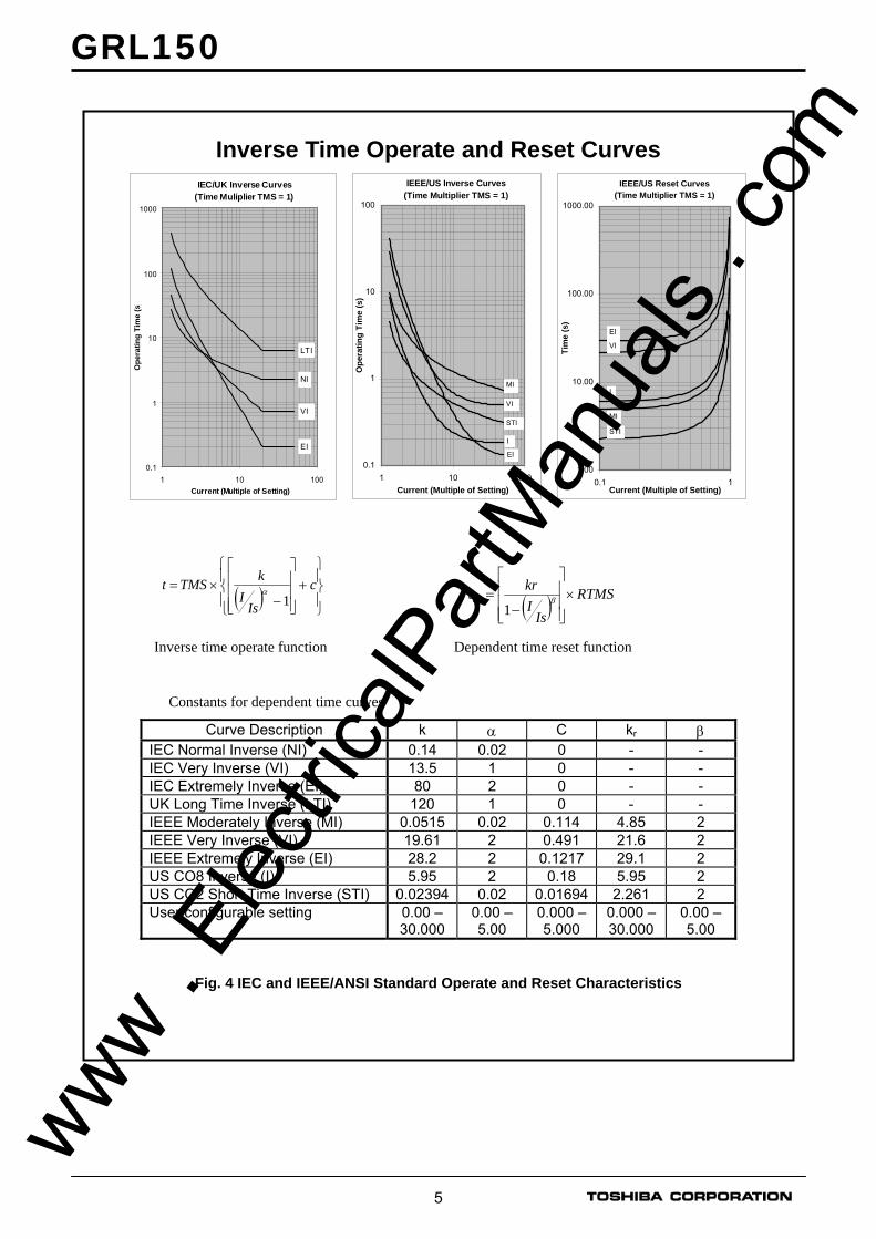
Phase Fault Overcurrent Protection GRL150 provides three phase overcurrent protections. Each provides four independent overcurrent thresholds. The first threshold may be set for inverse time or definite time operation. If inverse time is selected, then any one of nine curves may be chosen, including IEC and IEEE/ANSI standard characteristics. See Figure 4.
The first threshold has a programmable reset feature, selectable for instantaneous, definite time or dependent time reset. This feature can be used to protect against flashing fault conditions, or to grade correctly with electromechanical overcurrent relays.
The other overcurrent thresholds may be set for definite time, or instantaneous operation. These elements are immune to the effects of transformer magnetising inrush and dc offset transient over-reach.
All elements can be inhibited by binary input signals for operation in blocked overcurrent schemes.
Earth Fault Protection The standard earth fault protection is available in models GRL100-x10, and provides four independent overcurrent thresholds. Protection functionality is the same as for the phase fault elements, only with more sensitive current thresholds. www .
Elec
tricalP
artM
anua
ls . c
om

GRL150
4
The earth fault quantity is measured directly, by connecting the input in the residual circuit of the phase CTs.
Sensitive Earth Fault Protection GRL150-x20 provides earth fault protection with more sensitive settings for use in applications where the fault current magnitude may be very low. A four-stage overcurrent function is provided, with the first stage programmable for inverse time or definite time operation. The second stage provides definite time operation and runs after operation of the first stage. Three additional overcurrent thresholds are provided, each with a definite time delay.
The sensitive earth fault quantity is measured directly, using a dedicated core balance earth fault CT.
Phase Undercurrent Protection Protection against loss of load is provided by the phase undercurrent protection. Two independent stages are provided, each with a programmable definite time delay.
Thermal Overload Protection
The thermal overload feature provides protection for cables and other plant against the effects of prolonged operation under excess load conditions. A thermal replica algorithm is applied to create a model for the thermal characteristics of the protected plant. Tripping times depend not only on the level of overload current, but also on the level of prior load current, the thermal replica providing ‘memory’ of previous conditions.
The thermal characteristics of the system are defined by entering settings for full load current and thermal time constant. The GRL150 issues a trip according to the ‘cold’ and ‘hot’ curves specified in IEC60255-8 (see Figure 3), to prevent the protected system from exceeding its thermal capacity. The cold curve tripping times are applicable when the system is first energised, while the hot curves are relevant when the system has already been carrying some prior load for a period of time. An alarm output is also available to give early warning of high load current, set as percentage of thermal capacity.
Broken Conductor Protection The unbalance condition caused by an open circuited conductor is detected by the broken conductor protection. An unbalance threshold with programmable definite time delay is provided.
IEC60255-8 Thermal Characteristics
Thermal Curves (Cold Curve- no prior load)
0.01
0.1
1
10
100
1000
1 10
Overload Current (Multiple of k.IFLC)
Ope
rate
Tim
e (m
inut
es)
τ=1
τ=2
τ=5
τ=10
τ=20
τ=50
τ=100
Thermal Curves (Hot Curve -90% prior load)
0.001
0.01
0.1
1
10
100
1000
1 10
Overload Current (Multiple of k.IFLC)
Ope
rate
Tim
e (m
inut
es)
τ=100
τ=50
τ=20
τ=10
τ=5
τ=2
τ=1
( ) ⎥⎦
⎤⎢⎣
⎡
−= 22
2
..
FLCIkIILnt τ ; ( ) ⎥
⎦
⎤⎢⎣
⎡
−−
= 22
22
..
FLC
P
IkIIILnt τ
IEC60255-8 ‘Cold’ Curve IEC60255-8 ‘Hot’ Curve t = time to trip for constant overload current I (seconds) I = overload current (largest phase current) (pu) IP = previous load current (pu) k.IFLC (or Iθ) = thermal overload current setting (pu) τ = thermal time constant (seconds) Ln = natural logarithm
Fig. 3 IEC60255-8 Thermal characteristics
Circuit Breaker Fail Protection Two stage CBF protection provides outputs for re- tripping of the local circuit breaker and/or back- tripping to upstream circuit breakers. The CBF functions can also be initiated by external protections via a binary input if required.
Inrush Current Detector Second harmonic detection is provided for stabilization of the differential relay against magnetizing inrush currents during transformer energisation.
Cold Load Protection
The cold load function modifies the overcurrent protection settings for a period after energising the system. This feature is used to prevent unwanted protection operation when closing on to the type of load which takes a high level of current for a period after energisation.
www . El
ectric
alPar
tMan
uals
. com
GRL150
5
Inverse Time Operate and Reset Curves IEC/UK Inverse Curves
(Time Muliplier TMS = 1)
0.1
1
10
100
1000
1 10 100Current (Multiple of Setting)
Ope
ratin
g Ti
me
(s)
LTI
NI
VI
EI
IEEE/US Inverse Curves(Time Multiplier TMS = 1)
0.1
1
10
100
1 10 100Current (Multiple of Setting)
Ope
ratin
g Ti
me
(s)
MI
VI
STI
I
EI
IEEE/US Reset Curves(Time Multiplier TMS = 1)
1.00
10.00
100.00
1000.00
0.1 1Current (Multiple of Setting)
Tim
e (s
)
MI
VI
EI
STI
I
( ) ⎪⎭
⎪⎬
⎫
⎪⎩
⎪⎨
⎧+
⎥⎥⎥
⎦
⎤
⎢⎢⎢
⎣
⎡
−×= c
IsI
kTMSt1
α
( ) RTMSIs
Ikrtdo ×
⎥⎥⎥
⎦
⎤
⎢⎢⎢
⎣
⎡
−= β
1
Inverse time operate function Dependent time reset function
Constants for dependent time curves
Curve Description k α C kr β IEC Normal Inverse (NI) 0.14 0.02 0 - - IEC Very Inverse (VI) 13.5 1 0 - - IEC Extremely Inverse (EI) 80 2 0 - - UK Long Time Inverse (LTI) 120 1 0 - - IEEE Moderately Inverse (MI) 0.0515 0.02 0.114 4.85 2 IEEE Very Inverse (VI) 19.61 2 0.491 21.6 2 IEEE Extremely Inverse (EI) 28.2 2 0.1217 29.1 2 US CO8 Inverse (I) 5.95 2 0.18 5.95 2 US CO2 Short Time Inverse (STI) 0.02394 0.02 0.01694 2.261 2 User configurable setting 0.00 –
30.0000.00 – 5.00
0.000 – 5.000
0.000 – 30.000
0.00 – 5.00
Fig. 4 IEC and IEEE/ANSI Standard Operate and Reset Characteristics
www . El
ectric
alPar
tMan
uals
. com

GRL150
6
MONITORING FUNCTIONS Trip Circuit Supervision The circuit breaker tripping control circuit can be monitored by a binary input. Figure 5 shows a typical scheme. When the trip circuit is complete, a small current flows through the binary input, the circuit breaker auxiliary contacts and the trip coil. This current flows for both the breaker open and closed conditions.
GRL150
Binary Input CB Aux.
Contacts
CB Trip Coil Trip Output +ve Trip Supply -ve Trip
Supply
Circuit Breaker
Fig. 5 Trip Circuit Supervision Scheme
If the trip supply is lost or if a connection becomes open circuit then the binary input resets and a Trip Circuit Fail alarm is given in the form of an output contact operation and LCD or LED indication.
Automatic Self-Supervision Automatic monitoring of internal circuits and software is provided. In the event of a failure being detected, the ALARM LED on the relay fascia is illuminated, the ‘RELAY FAILURE’ binary output operates, and the date and time of the failure is recorded in the event record.
Circuit Breaker State Monitoring If two binary inputs are programmed to the functions ‘CB OPEN’ and ‘CB CLOSED’ then the CB State Monitoring function becomes active. In normal circumstances these inputs are in opposite states. If both show the same state then a ‘CB Defective’ alarm is raised.
Circuit Breaker Condition Monitoring The following CB condition monitoring functions are provided:
The trip counter increments the number of tripping operations performed. An alarm is issued when the count exceeds a user-defined setting.
The ∑Iy counter increments the value of current to the power ‘y’, recorded at the time of issuing the tripping signal, on a phase by phase basis
An alarm is issued when the count for any phase exceeds a user-defined setting.
The operating time monitor records the time between issuing the tripping signal and the phase currents falling to zero. An alarm is issued
when the operate time for any phase exceeds a user-defined setting.
The CB condition monitoring functions are triggered each time a trip is issued, and they can also be triggered by an external device via a binary input.
METERING AND RECORDING Metering The following data is continuously available on the relay fascia LCD and at a local or remote PC.
Local and remote terminal currents Differential currents Positive and negative phase sequence currents Relay element output status. Binary input and output status.
Event Record Records are stored for the 480 most recent events, time-tagged to 1ms resolution. The event record is available on the relay fascia LCD and at a local or remote PC. Events are recorded as follows:
Tripping operations Alarms Operation of protection elements Change of state of binary inputs / outputs Change of relay setting Failure detected by automatic supervision
Fault Record A relay trip initiates fault recording. Records are stored for the 8 most recent faults, time-tagged to 1ms resolution. The fault record is available on the relay fascia LCD and at a local or remote PC. Fault records include the following data:
Date and time of trip operation Operating phase Protection element responsible for trip Measured current data
Disturbance Record The relay can record 10 analog and 32 binary signals, initiated by relay tripping and initiating relay elements. Post-trigger recording time can be set, and the maximum number of records which can be stored is dependent on the recording times chosen.
Calendar and Time A calendar and time are provided for time-tagging of recorded data. Synchronisation with the GPS (Global positioning system) is possible using the IRIG-B port for Model 400 series. www .
Elec
tricalP
artM
anua
ls . c
om
GRL150
7
USER INTERFACE Relay Front Panel A user friendly interface is provided on the relay front panel. A menu-based system provides for easy programming of relay functions and access to real-time and stored data. The front panel includes the following features.
16 character, 2-line LCD with back lit 6 LEDs Keypad RS232C serial port for connection of local PC Monitoring jacks
Local PC Connection The user can communicate with the GRL150 from a local PC via the RS232C port on the front panel. Using RSM100 software, the user can view and modify settings, monitor real-time metering and analyse recorded data.
Relay Setting and Monitoring (RSM) GRL150 can be connected to the RSM system via the rear mounted serial communications port, using either RS485 or fibre optic connections (specified at time of order). Using RSM100 software, the user can view and modify settings, monitor real-time metering and analyse recorded data.
A maximum of 32 x 8 relays can be connected to the remote PC in multi-drop mode, by connection via a protocol converter G1PR2, with a maximum data transmission rate of 64kbps. The G1PR2 can be provided with maximum 8 ports.
IEC60870-5-103 Communications GRL150 supports the IEC60870-5-103 communication protocol. This protocol is used for communication with a substation control and monitoring system and is used to transfer measurand data, status data and general commands between the relay and the control system.
Relay Setting The user can modify relay settings either using the front panel keypad or using the RSM100 software from a local or remote PC. Password protection is available for added security.
Four settings groups are provided, allowing the user to set one group for normal conditions, while the other groups may be set to cover alternative operating conditions.
Using the RSM software, the user can create a settings file on a PC (without being connected to a relay), and store the file ready for download to a relay at a later date.
Binary Outputs GRL150 provides eight binary outputs including two for tripping, five for signals and one for relay failure alarm. Each of the programmable binary outputs is driven via a logic gate which can be programmed for OR gate or AND gate operation. Further, each output has a programmable reset characteristic, settable for instantaneous drop-off, delayed drop-off, or for latching operation. If latching operation is selected then an operated relay must be reset by the user, either by pressing the RESET button, by energising a binary input which has been programmed for ‘Remote Reset’ operation, or by a communications command.
Binary Inputs GRL150 provides eight programmable binary inputs. Each binary input is individually user-programmable for normal or inverted operation and for delayed pick-up and/or drop-off. Each input can also be used to switch relay operation to a different settings group.
General purpose alarm functions are also included. The user can define a text message for each alarm. Then when inputs associated with that alarm are raised, the defined text is displayed on the LCD.
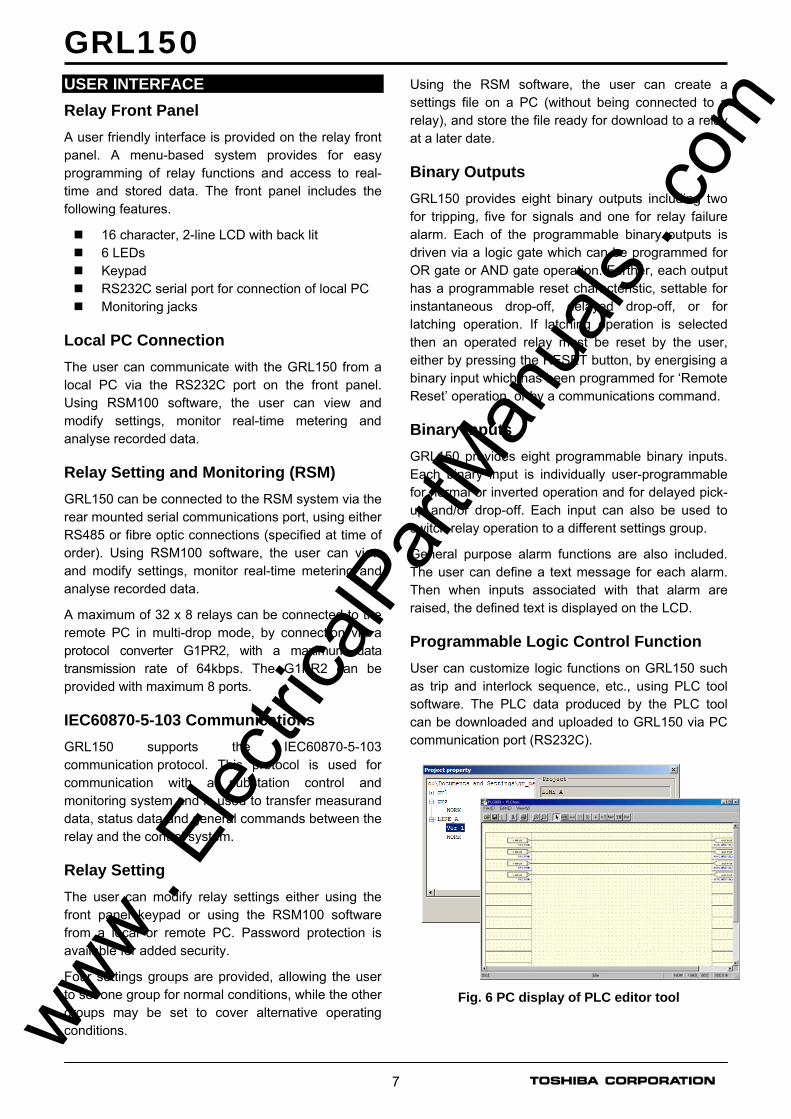
Programmable Logic Control Function User can customize logic functions on GRL150 such as trip and interlock sequence, etc., using PLC tool software. The PLC data produced by the PLC tool can be downloaded and uploaded to GRL150 via PC communication port (RS232C).
Fig. 6 PC display of PLC editor tool
www . El
ectric
alPar
tMan
uals
. com
GRL150
8
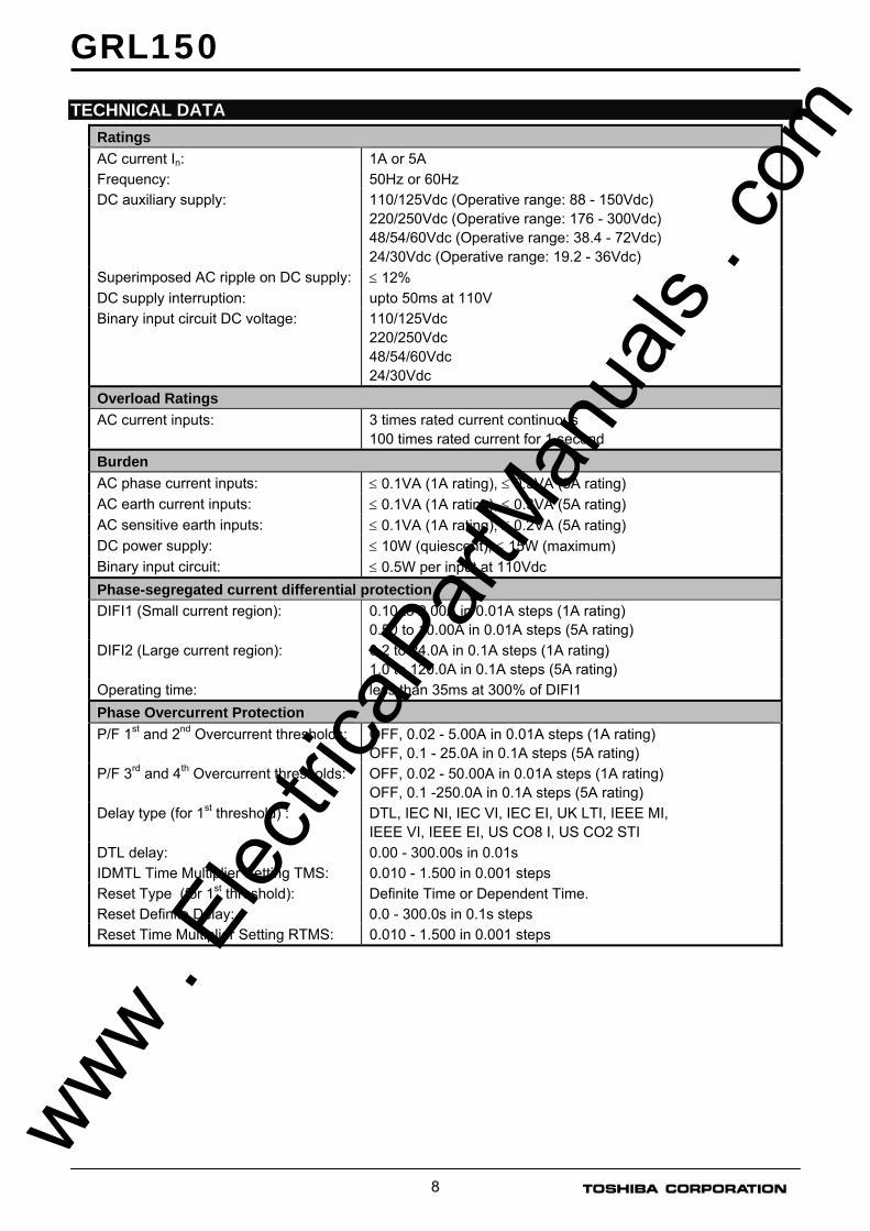
TECHNICAL DATA Ratings AC current In: 1A or 5A Frequency: 50Hz or 60Hz DC auxiliary supply: 110/125Vdc (Operative range: 88 - 150Vdc)
220/250Vdc (Operative range: 176 - 300Vdc) 48/54/60Vdc (Operative range: 38.4 - 72Vdc) 24/30Vdc (Operative range: 19.2 - 36Vdc)
Superimposed AC ripple on DC supply: ≤ 12% DC supply interruption: upto 50ms at 110V Binary input circuit DC voltage: 110/125Vdc
220/250Vdc 48/54/60Vdc 24/30Vdc
Overload Ratings AC current inputs:
3 times rated current continuous 100 times rated current for 1 second
Burden AC phase current inputs: ≤ 0.1VA (1A rating), ≤ 0.3VA (5A rating) AC earth current inputs: ≤ 0.1VA (1A rating), ≤ 0.3VA (5A rating) AC sensitive earth inputs: ≤ 0.1VA (1A rating), ≤ 0.2VA (5A rating) DC power supply: ≤ 10W (quiescent), ≤ 15W (maximum) Binary input circuit: ≤ 0.5W per input at 110Vdc Phase-segregated current differential protection DIFI1 (Small current region): 0.10 to 2.00A in 0.01A steps (1A rating)
0.50 to 10.00A in 0.01A steps (5A rating) DIFI2 (Large current region): 0.2 to 24.0A in 0.1A steps (1A rating)
1.0 to 120.0A in 0.1A steps (5A rating) Operating time: less than 35ms at 300% of DIFI1 Phase Overcurrent Protection P/F 1st and 2nd Overcurrent thresholds: OFF, 0.02 - 5.00A in 0.01A steps (1A rating)
OFF, 0.1 - 25.0A in 0.1A steps (5A rating) P/F 3rd and 4th Overcurrent thresholds: OFF, 0.02 - 50.00A in 0.01A steps (1A rating)
OFF, 0.1 -250.0A in 0.1A steps (5A rating) Delay type (for 1st threshold) : DTL, IEC NI, IEC VI, IEC EI, UK LTI, IEEE MI,
IEEE VI, IEEE EI, US CO8 I, US CO2 STI DTL delay: 0.00 - 300.00s in 0.01s IDMTL Time Multiplier Setting TMS: 0.010 - 1.500 in 0.001 steps Reset Type (for 1st threshold): Definite Time or Dependent Time. Reset Definite Delay: 0.0 - 300.0s in 0.1s steps Reset Time Multiplier Setting RTMS: 0.010 - 1.500 in 0.001 steps
www .
Elec
tricalP
artM
anua
ls . c
om
GRL150
9
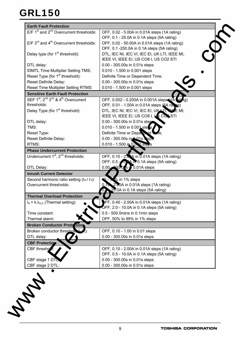
Earth Fault Protection E/F 1st and 2nd Overcurrent thresholds: OFF, 0.02 - 5.00A in 0.01A steps (1A rating)
OFF, 0.1 - 25.0A in 0.1A steps (5A rating) E/F 3rd and 4th Overcurrent thresholds: OFF, 0.02 - 50.00A in 0.01A steps (1A rating)
OFF, 0.1 -250.0A in 0.1A steps (5A rating) Delay type (for 1st threshold): DTL, IEC NI, IEC VI, IEC EI, UK LTI, IEEE MI,
IEEE VI, IEEE EI, US CO8 I, US CO2 STI DTL delay: 0.00 - 300.00s in 0.01s steps IDMTL Time Multiplier Setting TMS: 0.010 - 1.500 in 0.001 steps Reset Type (for 1st threshold): Definite Time or Dependent Time. Reset Definite Delay: 0.00 - 300.00s in 0.01s steps Reset Time Multiplier Setting RTMS: 0.010 - 1.500 in 0.001 steps Sensitive Earth Fault Protection SEF 1st, 2nd 3rd, & 4th Overcurrent thresholds:
OFF, 0.002 - 0.200A in 0.001A steps (1A rating) OFF, 0.01 - 1.00A in 0.01A steps (5A rating)
Delay Type (for 1st threshold): DTL, IEC NI, IEC VI, IEC EI, UK LTI, IEEE MI, IEEE VI, IEEE EI, US CO8 I, US CO2 STI
DTL delay: 0.00 - 300.00s in 0.01s steps TMS: 0.010 - 1.500 in 0.001 steps Reset Type: Definite Time or Dependent Time. Reset Definite Delay: 0.00 - 300.00s in 0.01s steps RTMS: 0.010 - 1.500 in 0.001 steps Phase Undercurrent Protection Undercurrent 1st, 2nd thresholds: OFF, 0.10 - 2.00A in 0.01A steps (1A rating)
OFF, 0.5 - 10.0A in 0.1A steps (5A rating) DTL Delay: 0.00 - 300.00s in 0.01A steps Inrush Current Detector Second harmonic ratio setting (I2f / I1f): Overcurrent thresholds:
10 - 50% in 1% steps 0.10 - 2.00A in 0.01A steps (1A rating) 0.5 - 25.0A in 0.1A steps (5A rating)
Thermal Overload Protection Iθ = k.IFLC (Thermal setting): OFF, 0.40 - 2.00A in 0.01A steps (1A rating)
OFF, 2.0 - 10.0A in 0.1A steps (5A rating) Time constant: 0.5 - 500.0mins in 0.1min steps Thermal alarm: OFF, 50% to 99% in 1% steps Broken Conductor Protection Broken conductor threshold (I2/I1): OFF, 0.10 - 1.00 in 0.01 steps DTL delay: 0.00 - 300.00s in 0.01s steps CBF Protection CBF threshold: OFF, 0.10 - 2.00A in 0.01A steps (1A rating)
OFF, 0.5 - 10.0A in 0.1A steps (5A rating) CBF stage 1 DTL: 0.00 - 300.00s in 0.01s steps CBF stage 2 DTL: 0.00 - 300.00s in 0.01s steps
www . El
ectric
alPar
tMan
uals
. com
GRL150
10
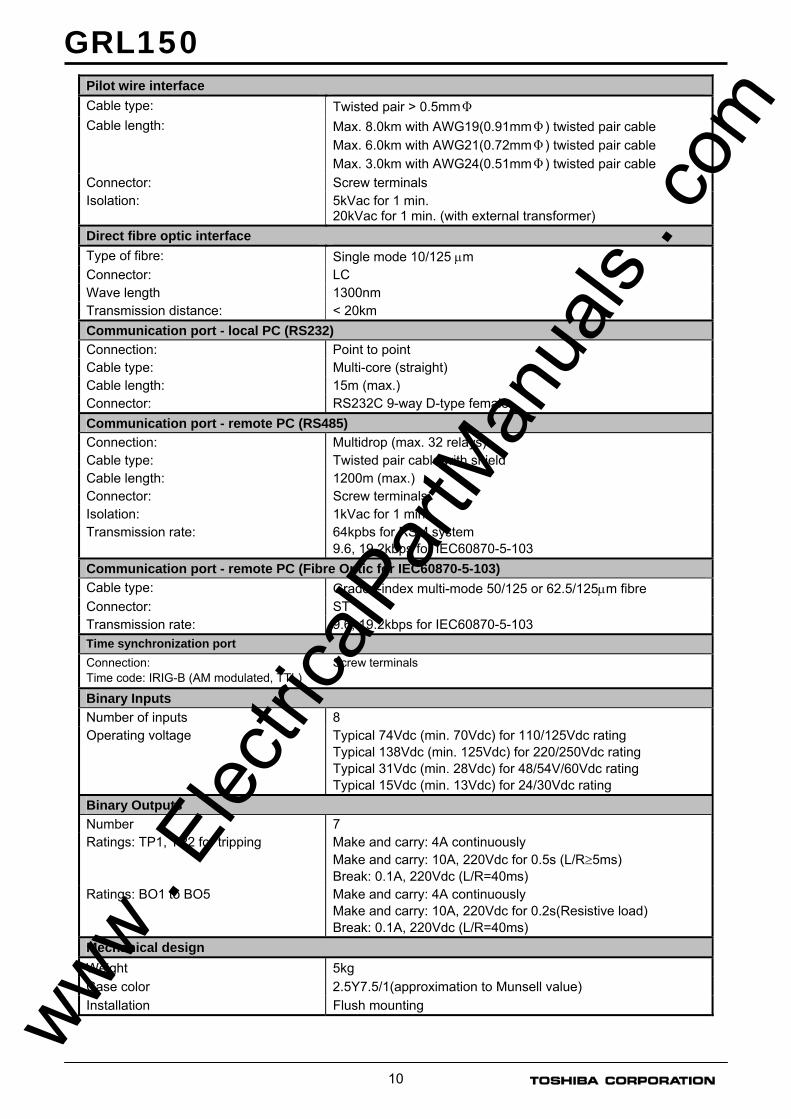
Pilot wire interface Cable type: Twisted pair > 0.5mmΦ Cable length: Max. 8.0km with AWG19(0.91mmΦ) twisted pair cable
Max. 6.0km with AWG21(0.72mmΦ) twisted pair cable Max. 3.0km with AWG24(0.51mmΦ) twisted pair cable
Connector: Screw terminals Isolation: 5kVac for 1 min.
20kVac for 1 min. (with external transformer) Direct fibre optic interface Type of fibre: Single mode 10/125 μm Connector: LC Wave length 1300nm Transmission distance: < 20km Communication port - local PC (RS232) Connection: Point to point Cable type: Multi-core (straight) Cable length: 15m (max.) Connector: RS232C 9-way D-type female Communication port - remote PC (RS485) Connection: Multidrop (max. 32 relays) Cable type: Twisted pair cable with shield Cable length: 1200m (max.) Connector: Screw terminals Isolation: 1kVac for 1 min. Transmission rate: 64kpbs for RSM system
9.6, 19.2kbps for IEC60870-5-103 Communication port - remote PC (Fibre Optic for IEC60870-5-103) Cable type: Graded-index multi-mode 50/125 or 62.5/125μm fibre Connector: ST Transmission rate: 9.6, 19.2kbps for IEC60870-5-103 Time synchronization port Connection: Time code: IRIG-B (AM modulated, TTL)
Screw terminals
Binary Inputs Number of inputs 8 Operating voltage
Typical 74Vdc (min. 70Vdc) for 110/125Vdc rating Typical 138Vdc (min. 125Vdc) for 220/250Vdc rating Typical 31Vdc (min. 28Vdc) for 48/54V/60Vdc rating Typical 15Vdc (min. 13Vdc) for 24/30Vdc rating
Binary Outputs Number 7 Ratings: TP1, TP2 for tripping Make and carry: 4A continuously
Make and carry: 10A, 220Vdc for 0.5s (L/R≥5ms) Break: 0.1A, 220Vdc (L/R=40ms)
Ratings: BO1 to BO5 Make and carry: 4A continuously Make and carry: 10A, 220Vdc for 0.2s(Resistive load) Break: 0.1A, 220Vdc (L/R=40ms)
Mechanical design Weight 5kg Case color 2.5Y7.5/1(approximation to Munsell value) Installation Flush mounting
www . El
ectric
alPar
tMan
uals
. com
GRL150
11
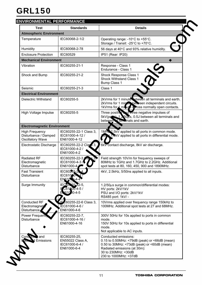
ENVIRONMENTAL PERFORMANCE Test Standards Details
Atmospheric Environment Temperature IEC60068-2-1/2 Operating range: -10°C to +55°C.
Storage / Transit: -25°C to +70°C. Humidity IEC60068-2-78 56 days at 40°C and 93% relative humidity. Enclosure Protection IEC60529 IP51 (Rear: IP20) Mechanical Environment Vibration IEC60255-21-1 Response - Class 1
Endurance - Class 1 Shock and Bump IEC60255-21-2 Shock Response Class 1
Shock Withstand Class 1 Bump Class 1
Seismic IEC60255-21-3 Class 1 Electrical Environment Dielectric Withstand IEC60255-5 2kVrms for 1 minute between all terminals and earth.
2kVrms for 1 minute between independent circuits. 1kVrms for 1 minute across normally open contacts.
High Voltage Impulse IEC60255-5 Three positive and three negative impulses of 5kV(peak), 1.2/50μs, 0.5J between all terminals and between all terminals and earth.
Electromagnetic Environment High Frequency Disturbance / Damped Oscillatory Wave
IEC60255-22-1 Class 3, IEC61000-4-12 / EN61000-4-12
1MHz 2.5kV applied to all ports in common mode. 1MHz 1.0kV applied to all ports in differential mode.
Electrostatic Discharge IEC60255-22-2 Class 3, IEC61000-4-2 / EN61000-4-2
6kV contact discharge, 8kV air discharge.
Radiated RF Electromagnetic Disturbance
IEC60255-22-3 Class 3, IEC61000-4-3 / EN61000-4-3
Field strength 10V/m for frequency sweeps of 80MHz to 1GHz and 1.7GHz to 2.2GHz. Additional spot tests at 80, 160, 450, 900 and 1890MHz.
Fast Transient Disturbance
IEC60255-22-4, IEC61000-4-4 / EN61000-4-4
4kV, 2.5kHz, 5/50ns applied to all inputs.
Surge Immunity IEC60255-22-5, IEC61000-4-5 / EN61000-4-5
1.2/50μs surge in common/differential modes: HV ports: 2kV/1kV PSU and I/O ports: 2kV/1kV RS485 port: 1kV/ -
Conducted RF Electromagnetic Disturbance
IEC60255-22-6 Class 3, IEC61000-4-6 / EN61000-4-6
10Vrms applied over frequency range 150kHz to 100MHz. Additional spot tests at 27 and 68MHz.
Power Frequency Disturbance
IEC60255-22-7, IEC61000-4-16 / EN61000-4-16
300V 50Hz for 10s applied to ports in common mode. 150V 50Hz for 10s applied to ports in differential mode. Not applicable to AC inputs.
Conducted and Radiated Emissions
IEC60255-25, EN55022 Class A, IEC61000-6-4 / EN61000-6-4
Conducted emissions: 0.15 to 0.50MHz: <79dB (peak) or <66dB (mean) 0.50 to 30MHz: <73dB (peak) or <60dB (mean) Radiated emissions (at 30m): 30 to 230MHz: <30dB 230 to 1000MHz: <37dB
www . El
ectric
alPar
tMan
uals
. com

GRL150
12
Test Standards Details European Commission Directives
89/336/EEC Compliance with the European Commission Electromagnetic Compatibility Directive is demonstrated according to EN 61000-6-2 and EN 61000-6-4.
73/23/EEC Compliance with the European Commission Low Voltage Directive is demonstrated according to EN 50178 and EN 60255-5.
EXTERNAL 20kV ISOLATION TRANSFORMER (OPTION)
Type EB-110
Isolation voltage 20kV
Connection terminal Screw terminal
PROTOCOL CONVERTER G1PR2 (OPTION)
Ratings Power supply: 110Vdc/100Vac Operative range: 88 - 150Vdc of 110Vdc rated voltage
80 - 120Vac of 100Vac rated voltage 220Vdc/200Vac Operative range: 170 - 300Vdc of 220Vdc rated voltage 200 - 240Vac of 200Vac rated voltage 48Vdc Operative range: 38.4 - 72Vdc
Burden: less than 20W Communication port RS232C interface Connector type Cable type
RS232C 9-pin D-subminiature connector female Multi-core (straight)
RS485 interface Connector Cable type
Screw terminals (Phoenix Contact, FRONT type) Twisted pair cable
Optical interface Operative Range: Wavelength: Connector type: Fibre type:
less than 1.2km with 62.5/125μm GI fibre (3dB/km) 820nm ST 62.5/125μm glass fibre
IRIG-B Connector
Screw terminals (Phoenix Contact, FRONT-MSTB type)
Mechanical design Enclosure Protection Weight Installation
IEC60529, IP20 (excluding terminal parts) 5 kg Flush mounting
Atmospheric Environment Temperature Humidity
IEC60068-2-1/2 IEC60068-2-3
Operating range: -10°C to +55°C. Storage / Transit: -25°C to +70°C. 56 days at 40°C and 93% relative humidity.
www .
Elec
tricalP
artM
anua
ls . c
om

GRL150
13
ORDERING 1. Line Differential Protection 2. Protocol Converter (Option)
Type:
Protocol converter G1PR2
Model: 1 port, Electrical signal (RS485) 4 ports, Electrical signal (RS485) 8 ports, Electrical signal (RS485) 8 ports, Electrical signal (RS485): Max. 8, Optical signal: Max. 1 8 ports, Electrical signal (RS485): Max. 8, Optical signal: Max. 4 8 ports, Electrical signal (RS485): Max. 4, Optical signal: Max. 8 1 port, Electrical signal (RS485) or Optical signal 1 port, Optical signal 4 ports, Optical signal 8 ports, Optical signal
101 104 108 118 148 184 111 110 140 180
AC power supply rating:
AC 100/DC 110V AC 200/DC 220V DC 48V
10 50 A0
External time synchronisation:
None. Provided. (IRIG-B)
00 10
G1PR2 − A − −
Relay type:
Line differential protection GRL150
Telecommunication Pilot wire interface Either pilot wire or optical interface
1 4
Back-up Scheme 3 phase OC Protection (Standard) 3 phase OC and EF Protection 3 phase OC and Sensitive EF Protection
0 1 2
Ratings: 1A, 50Hz, 110V/125Vdc 1A, 60Hz, 110V/125Vdc 5A, 50Hz, 110V/125Vdc 5A, 60Hz, 110V/125Vdc 1A, 50Hz, 220V/250Vdc 1A, 60Hz, 220V/250Vdc 5A, 50Hz, 220V/250Vdc 5A, 60Hz, 220V/250Vdc 1A, 50Hz, 48V/54V/60Vdc 1A, 60Hz, 48V/54V/60Vdc 5A, 50Hz, 48V/54V/60Vdc 5A, 60Hz, 48V/54V/60Vdc 1A, 50Hz, 24/30Vdc 1A, 60Hz, 24/30Vdc 5A, 50Hz, 24/30Vdc 5A, 60Hz, 24/30Vdc
1 2 3 4 5 6 7 8 A B C D E F G H
Communications: RS485 Fibre optic Dual RS485 RS485 + Fibre optic
1 2 3 9
GRL150 − 0A − 0 − 0
www . El
ectric
alPar
tMan
uals
. com
GRL150
14
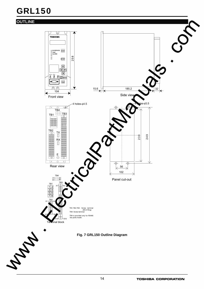
OUTLINE
Fig. 7 GRL150 Outline Diagram
185.2 32 15.6
Side view 104
2 5
8
IN SERVICE TRIP ALARM
VIEW
RESET
Front view
END
CELCAN ENTER
2 4
9
Panel cut-out
56
102
4 holes-φ5.5
2 3
9
4 holes-φ4.5
TB3
Rear view
E
TB1
TB2
TB4
Terminal block
TB3A1 B1
A18 B18
TB1,TB2,TB3: Screw terminal (M3.5 Ring)
TB4: Screw terminal TB4 is provided only for RS485 two ports model.
1 2 3 4 5 6
TB1
TB2 A1 B1
A10 B10
7 8
A1 A3TB4
B1 B3
A B 0V
TX
RX
www . El
ectric
alPar
tMan
uals
. com

GRL150
15
EXTERNAL CONNECTION DIAGRAM
Fig. 8 External Connection for model GRL150-100/400
TB3-A2
COM1-B
COM1-A
A1
A3
RS485 I/F for RSM, IEC60870-5-103
COM1-0V
B4TP1
A5B5A6B6
TP2A7B7
A8B8BO1
A9B9
A10B10
BO2
BO3
TB3-A16A17
TX
RX
B14
FAILB15
4 3 2
6 5
CT
FRAME EARTH
Ia
Ib
Ic
TB1- 1 TB3-
A4
A B C
DD FAIL.
(-) (+)
+5Vdc
0V
DC SUPPLY DC-DC
RELAY FAIL.≥1
TB2- A9
B9
CASE EARTHE
A10
B10
FRAME EARTH(∗1)
TB4-A2
COM2-B
COM2-A
A1
A3
B3
RS485 I/F for IEC60870-5-103 (Dual port model only: option)
COM2-0V
B1
B2
TB3-B1B2
Pilot wire Interface
Optical Interface (*2)
For telecommunication
(*1)This connection is connected by wire link before shipment.
(*2)Model 100 is not provided with Optical interface.
(*3)Model 100 is not provided with IRIG port.
IRIG (*3)
(P)
B1 BI1
B2 BI2
B3 BI3
A2
A3
B4 BI4A4
B5 BI5A5
TB2- A1
(N)
BI1 COMMAND
BI2 COMMAND
BI3 COMMAND
BI4 COMMAND
BI5 COMMAND
B6 BI6A6
B7 BI7A7
B8 BI8A8
BI6 COMMAND
BI7 COMMAND
BI8 COMMAND
A11B11
A12B12A13B13
BO4
BO5
A14
Fibre optic I/F for IEC 60870-5-103 (option)
www . El
ectric
alPar
tMan
uals
. com

GRL150
16
Fig. 9 External Connection for model GRL150-110/410
TB3-A2
COM1-B
COM1-A
A1
A3
RS485 I/F for RSM, IEC60870-5-103
COM1-0V
Fibre optic I/F for IEC 60870-5-103 (option)
B4TP1
A5B5A6B6
TP2A7B7
A8B8BO1
A9B9
A10B10
BO2
BO3
TB3-A16A17
TX
RX
B14A14FAILB15
4 3 2
6 5
CT
FRAME EARTH
8 7
Ia
Ib
Ic
Ie
TB1- 1 TB3-
A4
A B C
DD FAIL.
(-) (+)
+5Vdc
0V
DC SUPPLY DC-DC
RELAY FAIL.≥1
TB2- A9
B9
CASE EARTHE
A10
B10
FRAME EARTH(∗1)
TB4-A2
COM2-B
COM2-A
A1
A3 B3
RS485 I/F for IEC60870-5-103 (Dual port model only: option)
COM2-0V
B1
B2
TB3-B1B2
Pilot wire Interface
Optical Interface (*2)
For telecommunication
(*1)This connection is connected by wire link before shipment.
(*2)Model 110 is not provided with Optical interface.
(*3)Model 110 is not provided with IRIG port.
IRIG (*3)
A11B11
A12B12A13B13
BO4
BO5
(P)
B1 BI1
B2 BI2
B3 BI3
A2
A3
B4 BI4A4
B5 BI5A5
TB2- A1
(N)
BI1 COMMAND
BI2 COMMAND
BI3 COMMAND
BI4 COMMAND
BI5 COMMAND
B6 BI6A6
B7 BI7A7
B8 BI8A8
BI6 COMMAND
BI7 COMMAND
BI8 COMMAND
www . El
ectric
alPar
tMan
uals
. com

GRL150
17
Fig. 10 External Connection for model GRL150-120/420
TB3-A2
COM1-B
COM1-A
A1
A3
RS485 I/F for RSM, IEC60870-5-103
COM1-0V
Fibre optic I/F for IEC60870-5-103 (option)
B4TP1
A5B5A6B6
TP2A7B7
A8B8BO1
A9B9
A10B10
BO2
BO3
TB3-A16A17
TX
RX
B14A14FAILB15
4 3 2
6 5
CT
FRAME EARTH
8 7
Ia
Ib
Ic
Ise
TB1-1 TB3-
A4
A B C
Core balance CT
DD FAIL.
(-) (+)
+5Vdc
0V
DC SUPPLY DC-DC
RELAY FAIL.≥1
TB2- A9
B9
CASE EARTHE
A10B10
FRAME EARTH(∗1)
TB4-A2
COM2-B
COM2-A
A1
A3
B3
RS485 I/F for IEC60870-5-103 (Dual port model only: option)
COM2-0V
B1
B2
TB3-B1B2
Pilot wire Interface
Optical Interface (*2)
For telecommunication
IRIG (*3)
(*1)This connection is connected by wire link before shipment.
(*2)Model 120 is not provided with Optical interface.
(*3)Model 120 is not provided with IRIG port.
A11B11
A12B12A13B13
BO4
BO5
(P)
B1 BI1
B2 BI2
B3 BI3
A2
A3
B4 BI4A4
B5 BI5A5
TB2-A1
(N)
BI1 COMMAND
BI2 COMMAND
BI3 COMMAND
BI4 COMMAND
BI5 COMMAND
B6 BI6A6
B7 BI7A7
B8 BI8A8
BI6 COMMAND
BI7 COMMAND
BI8 COMMAND
www . El
ectric
alPar
tMan
uals
. com

GRL150
18
ACCESSORIES
External 20kV Isolation Transformer EB-110 (Option)
4 holes for M6 screw (for mounting)
M4 screw M5 screw
106
207
62
26.2 66.719
13.1
U V E
v u
152.
4
170
190
10
18.8
13
0 8.8
84.8
67.8
TB2 TB1
Fig. 11 Outline & Dimensions
Fig. 12 External Connections
TB2 TB1 u v
U V
E
Pilot wire side (High-voltage side)
Relay side
www . El
ectric
alPar
tMan
uals
. com

GRL150
19
MEMO
www . El
ectric
alPar
tMan
uals
. com

www . El
ectric
alPar
tMan
uals
. com