- tooled-up.com supplies tools, hand …€¦ · · 2012-01-26 before use please ... fixing roe!...
TRANSCRIPT

OPERATOR’S MANUAL AND PARTS LIST 80lb Spreader - THS80
Spares & Support: 01793 333212
www.thehandy.co.uk Before use please read & understand this manual, paying particular
attention to the safety instructions. 23/05/2011

1. HELPFUL HINTS:
READ THE DIRECTIONS BEFORE ASSEMBLY
WHEN ALL ELSE FAILS, READ THE DIRECTIONS AGAIN
• If your spreader does not spread evenly, be sure the FRONT on the gear box points tothe front of the spreader. The impeller must turn clockwise. Reversing the gear box willcause the impeller to turn counter clockwise. Clean the impeller plate after each use.Fertilizer stuck on the impeller blades will cause uneven spreading.
• Your spreader is designed to be pushed at three miles per hour, which is a brisk walkingspeed. Slower or faster speeds will change the spread patterns. Wet fertilizer will alsochange the spread pattern and flow rate. Clean your spreader thoroughly after eachuse. Wash between the shut off plate and bottom of the hopper.
• Gears are permanently lubricated at the factory. Do not open the gear box or dirt mayenter.
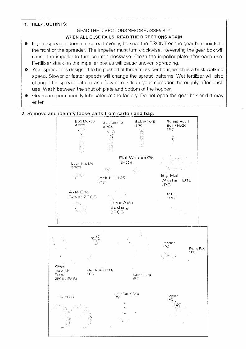
2. Remove and identify loose parts from carton and bag.
Bolt 1'v16x654PCS
Bolt 1'v16x406F'CS
Bolt 1'v1~)x4~)
1PCRound HeadBolt 1'v14x201PC
Lock Nut 1'v16SPCS
Flat Washer064PCS
Lock Nut MS1PC
Big FlatW2.sher 0161PC
Axle EndCover 2PCS
Inner" AxleBushing2PCS
R Pin1PC
Impeller1PC Fixing Roe!
1PC
WheelAssemblyFrame2PCS (1PAIR)
Tire 2PCS
Handle Assembly1PC Support LeeJ
1PC
C;C1r Box & ;\xlelPC Hopper
1PC

STEP 1: Install impeller onto the Gear Box & Axle Asse mbly. Insert Screw M4x20 throug himpeller then through Gear Box Axle.
Impell.er
BoltM4x20
i
I Gear Box & Axle
...'
". , ....,
Install impelleronto the Gear Box& Axle Assemble.Insert ScrewM4x20 throughimpell.er thenthrough Gear BoxAxle.
______J

STEP 2: Attach the Wheel Assembly Frame on each side of the Gear Box Axle and FixingConnecting Rod, insert two bolts M6x40 into the Fixing Connecting Rod through WheelAssembly Frame. Make sure the hole on Axle of Gear Box is on the right side when assembly asshown. Attach Wheel Assembly Frames and Support Leg onto Hopper using bolts M6x65, nutsM6 and Flat Washers 06. Note: The bolts and nuts needn't be tightened yet.
Connect two wheel frames
with tile axle using bolts M6x40and flat washers 06.
Hopper
Flat \li1ashGr
-.··.-.Llolt v16x65
Left V\lheel
bly I-r",n-lO
Gear Box
Bolt
rv16x40
Ri9ht \1"th DC)I
Assembty .... rr)n'C'.
Make sure the hole on axle of Gear
Box is to be on this side when
assembly.
Bolt
iv16x/l0

STEP 3: Insert Inner Axle Bushing into Outer Axle Bushing and make sure they are tight neatly.Install right Tire Assembly to right Axle using bolt M5x45 and lock nut M5, and then install theCap onto right Axle using a wooden or rubber hammer. Now install left Tire Assembly to left Axle,put a flat washer 016 and install the Cap onto left Axle using a wooden or rubber hammer.
Bushing and make sum they am tight property.
Cap
Inner Axle
Bushing
Hopper Assembly
~;15
Lock Nut
Bolt lv15x45
Attach right Tire Assembly
to right Axle using Bolt r,;15x45
and Lock Nut :\115. Install the Cap onto
Axto using a wooden
or ru hammer.
6
Axle End
Cap
Inner Axle Bushing
Install the Cap onto
Axle using a wooden
or rubber hammer.<~'''.<'':'",•.
Flat \f'\/asher

STEP 4: Insert Upper Handle into the Support Leg and tighten using bolts M6x40 and LockNuts M6. NOW GO BACK AND TIGHTEN ALL NUTS AND BOLTS STARTING WITH FIRSTSTEP. DO NOT OVER TIGHTEN .
Handle
Bolt IVIO,)\,+U
Hopper Assembly

P 5: (1) Insert the Steel Wire head of control cable into the small hole on Gauge and LeverAssembly. (2)Release two bolts M5x1 0 and nuts on Press Plate. (3) Put the Plastic Tube into theslot of Press Plate. (4). Tighten two bolts M5x10 and nuts again.
Insert the .Stce:1 \jviro head of
Control Cable into the: small hole) on
C3augo and Lover ;\ssombly.
Put th laslic
TUfX: into the slot
P!(J10.
In
se Pin

STEP 6: AD JUSTMENTS. When you have finished all above steps, and if you find the threebig ho les at th e bottom of hopper just match the three ho les of adjustable plate. You don'tneed to do the fo llowing steps . If they do not match neatly, you may need to do thefoll ow ing steps . (1)Release two bolts M5x10 on clamp as shown . (2) . Push the handle to thelowest position <downwards>, use your hand to adjust the adjustab le plate so as to make surethree big holes at the bottom of hopper just match the threes holes of adju stable plate neatly. (3) .And then tighten the bolts and nuts on clamp again .To operate th is spreader, push the hand le to th e top position (upwards). You may movethe posit ion of Wing nut on Gaug e & Lever to adjust the spacer on the three holesbetween the hopper and the adj ustable pl ate as per yo ur req uirements when spreading.
rVlove the position of this nut co uld adjust
t il e spacer of three holes between hopperand adjustab le plate as per your need
2 . Push the ha nd le to the lowes t when spread ing . .
pos ition-cdownward s>, use you r hand toadjust the ad justable plate so as to makesure three big holes at the bottom ofho pper just matc h the threes ho les ofadjustable plate nea tly.
ITo op erate th is spread er. push
til e handle to the top po sition.
1.Re lease thesetwo bolts.
3.Tighten thesetwo boltsaga in.
Irnpeller must be turningin this direction whenpush forward.

OPERATING INSTRUCTIONS
Before filling the hopper, become familiar with the operation of this spreader. • Check the proper setting for the material to be used in the RATE SETTING CHART
included with this spreader. • Move the stop bolt on the rate gauge assembly to the proper setting. • While pushing the spreader forward, pull the control lever back to the stop bolt. • Before you stop moving, push the lever forwards to close the flow holes. • When finished, empty any remaining material from the hopper. • Thoroughly wash the spreader and allow it to dry before storing. No oiling is necessary. • Remove the agitator when using Rock Salt to prevent gearbox damage.

PRECISION SPREADERSSUPPLEMENTARY INSTRUCTIONS
FOR UK MATERIALSUSING YOUR SPREADERPrecision spreaders are designed to spread dry, powdered or granulated, materials thinly and evenly over anyreasonably smooth surface.Proceed as follows1. Make certain that the material is dry and “free running”. If in doubt pass it through a sieve with 3mm (1/8”)
mesh to remove lumps.2. Set rate-setting dial to No2.3. Fill the hopper approximately ¾ full.4. Push the spreader forward and open feed gate (push knob down) whilst in motion. If spread is uneven or
inadequate pull up lever and re-set micro-dial to a higher number. Repeat until satisfactory distribution isobtained.
N.B. ALWAYS MOVE OFF BEFORE OPENING FEED-GATE.ALWAYS CLOSE FEED-GATEBEFORE STOPPING.
SUGGESTED SETTINGS FOR POPULAR TURF DRESSINGS:MANUFACTURER PRODUCT NAME OR
ANALYSISSEASON OF USE RECOMM
ENDEDAPPLICATION RATE
GUIDESETTING
G/M2 OZ’S/YD2FISONS EVERGREEN 90 35 1 18
EXTRA 35 1 16LAWNFOOD 35 1 16MOSSKILL 35 1 16
EIGBY TAILOR 9.7.7/7.7.7./3.12.12 Spring & Autumn 70 2 28PROFESSIONAL 10.15.10/12.6.6. Spring & Autumn 35 1 24
ORGANIC N Spring 35 1 16MINIGRAN All Seasons 35 1 20
MICRO FINE All seasons 35 1 16
J A BOWERS FEED & WEED 70 2 24MOSSKILLER 70 2 24LAWNSAND 140 4 20LAWNFOOD Spring & Autumn 70 2 28LAWNFOOD Autumn 70 2 28
PEACOCK ICE MELTER Winter (Paths) 150 4 20
P.B.I. TOPLAWN Autumn & Winter 60 2 20

O.M.SCOTT WINTERIZER Autumn & Winter 20 ½ 12MOSS CONTROL Autumn 20 ½ 12LAWN BUILDER Spring & Summer 20 ½ 12
ICI PROFESSIONAL SPORTSFIELD Spring & Summer 35 1 16(RANGE) Autumn Feed 35 1 16
Nitro Green Plus 35 1 16FINE TURF Spring & Summer 35 1 16
(RANGE) Autumn Feed 35 1 16Fine Green N.K. 35 1 16Nitro with Iron 35 1 16
STANDARD Spring & Summer 35 1 16(RANGE) Autumn Feed 35 1 16
ICI HOMEOWNER GRASSHOPPER Apr, May, June, Sept 52 1.5 12LAWNFEED Apr-Aug Inclusive 70 2 16
MOSSKILLER Mar-Oct Inclusive 70 2 16
VITAX WEED & FEED Spring & Summer 35 1 8WEED & MOSSKILL Spring 70 2 12
Q4 RANGE 35 1 8KEY N Spring & Summer 35 1 16
GROWERS RANGE FINE X Mar-Aug Inclusive 35 1 16FINE X Mar-Aug Inclusive 70 2 20
LAWNSAND Spring & Summer 35 1 12LAWNSAND Spring & Summer 140 4 24TURF TONIC Any Time 35 1 12TURF TONIC Any Time 70 2 16
WEED & FEED EXTRA Apr-Sept Inclusive 35 1 16WEED & FEED EATRA Apr-Sept Inclusive 70 2 12
CF GRAN 1&4 Spring & Summer 35 1 24CF GRAN 2 Autumn & Winter 35 1 24
MICRO GRAN 1,3&4 Spring & Summer 35 2 8MICRO GRAN 2 Autumn & Winter 70 2 12
PARKER No.1 Spring & Summer 35 1 12No.2 Spring & Summer 35 1 12No.4 Autumn & Winter 35 1 12No.5 Spring & Summer 35 1 8No.6 Spring & Summer 35 1 8No.7 Autumn & Winter 35 1 8
VARIOUS GROMORE (Granules) Spring & Summer 35 1 24N.B. the above settings are suggestions only. Even branded materials may vary in grain size, humidity,Density etc. If you are in doubt either (1) Choose a lower setting than that suggested above or (2) Start atdial setting No.2 and progressively dial higher numbers until an even spread is achieved. Lock the dialclamp and apply material. This will, give rather less than the manufacturers of the material recommends.

PARTS DRAWING
.:> ,'). ) .<..
.3,9
.) r"_
.) I
/
14.4 !
18
.31
46'
15
16
17
1.9
7' ?,'~
,cf""""""""---" 24
1 1to
,'5 :5
o/'"-...; (J(
2/
,'r
.).J
.) r;~- ,-j
29
28
23
2/
,:!-/
20
30
.) .)."] /3

PARTS LIST
-
Ref# Description Qty Ref# Description Qty
1 Bolt M6x25 1 25 Lock Nut M6 12----- " --,._----
1 Sup po rt-L~~---.._-
2 Lock Washer 08 1 26 1-------- -- -
I Wheel Assembly ~~_~~e(Right)3 Gauge and Lever Assembly 1 27 1.~,,-,~-,~_.-
4 Adjust Handle Pole 1 28 Thin Washer 1I - .. .- -,~'"---_..,-
5 Adjust Handle A 1 29 Pneumatic Wheel 2
Adjust Handle B 1 30 lVc1~IIt:::1 016 1
Screw 04x18 1 31 Axle End Cover 2
Handle Grip 1 32 Inner Axle Bushing 2
Spacer 1 33 Outer Axle Bushing
Wing Nut 1 34 Gear Box & Axle Assemble
11 Hopper 1 35 Screw M4x20 1
Pin 02x60 \/11=))(41=) 1
Cover Press Plate 1
I\/lh)(hl=) 4 38 Rod 1
15 Adjustable Plate 1 39 SGI t:::w M5x1 0
1 Flat Washer 04 3 40 Nylon Washer
Screw 04x12 41 Big Flat Washer 06
18 vAv 11t:::t:::' Assembly Frame(Left) Handle
19 1111I-Jellt:::1
Bolt M6x35 Screw 05x15
Lock Nut M5 Cap
22 Line Clamp Bottom Plate 1 End Cap
23 Tube End Cap 4 47 Fixing Connection Rod
24 Bolt M6x40 4
Handy Distribution Spares and Helpline 01793 333220


To order spare parts and see the complete range of garden machinery and garden equipment from Handy, visit:
www.thehandy.co.uk
Spares & Support: 01793 333212