· type 12101.3 12102.3 12103.3 12104.3 ... 5. ... seal material nbr (perbunan), silicone-free,...
TRANSCRIPT

www.bestapower.com
DATA SHEETS A62/A180

Conductix-Wampfler GmbH | [email protected] | www.bestapower.com
Contents Data sheet no. Issue
Rail sections A62 B01E Mar. 2010Rail sections A180 B02E Mar. 2010Accessories A62 / A180 B03E Mar. 2010Curved rail sections B04E Mar. 2010
Rail connections A62 C01E Mar. 2010Rail connections A180 C02E Mar. 2010
End pieces A62 / A180 D01E Mar. 2010
Rail mounting A62 E01E Mar. 2010Rail mounting A180 E02E Mar. 2010
Tapping carriages F01E Mar. 2010Tapping carriage without FRL F02E Mar. 2010Tapping carriage with 3/8" FRL units F03E Mar. 2010Tapping carriage with 1/2" FRL units F04E Mar. 2010Tapping carriage with 1/2" injection lubricator F05E Mar. 2010Tapping carriage accessories F10E Mar. 2010
Detaching devices G01E Mar. 2010
Tool carriages H01E Mar. 2010Tool carriages H02E Mar. 2010
Equipment and cable carriages I01E Mar. 2010
Work stations K01E Mar. 2010Work stations K02E Mar. 2010Tool holders K03E Mar. 2010Tool holders K04E Mar. 2010
Energy carrier system A62 / A180 L01E Mar. 2010
Conductor rails A62 / A180 M01E Mar. 2010
Festoon systems N01E Mar. 2010
Operation principle R01E Mar. 2010
Flow rate / pressure loss S01E Mar. 2010
Tools / assembly aids W01E Mar. 2010
ContentsData sheet no. 001EIssue: March 2010 Page 2/2
Signs and symbols
Notice: To prevent damages to equipment, property and the environment
Dangerous situation that can lead to injury or death

Conductix-Wampfler GmbH | [email protected] | www.bestapower.com
3. Rails with integrated connection plates G1/2"Table 3Type 12101.3 12102.3 12103.3 12104.3Length A mm 1500 3000 4500 6000Spacing B mm -- 1500 1500 1500No. of connection plates qty 1 2 3 4Threaded connection T 1/2" 1/2" 1/2" 1/2"Weight kg 4.1 8.2 12.3 16.4
Subject to technical modifications
Rail sections A62Data sheet no. B01EIssue: March 2010 Page 1/2
1. Rails with integrated tapping valvesTable 1
The compressed air rail has the following functions:a) Energy carrier system: - supply of compressed air - mounting of a conductor railb) Support for tapping valves and connection platesc) Rail for work stations, tool holders and carriagesd) Support for accessories, energy carrier system etc.
Using coupling pieces, the rails can be linked to form tracks of any length. They are made from a hollow aluminium section and are suitable for dry and lubricated compressed air (also respiratory air). All compo-nents are silicone-free.
The four basic versions1. Rails with integrated tapping valves for tapping carriages. Table 12. Rails without tapping valves and connection plates, e.g. for drawing air via fixed tapping points (type 6720) or tapping screw fittings (type 6850). Table 23. Rails with integrated connection plates for direct hose connection. Table 34. Rails with integrated outlet connectors, e.g. for energy carrier systems. Table 4
Type 12101.1 12102.1 12103.1 12104.1 12104.1013Length A mm 1500 3000 4500 6000 6000Spacing B mm -- 1500 1500 1500 750No. of tapping valves qty 1 2 3 4 8Weight kg 4.1 8.2 12.3 16.4 17.0
2. Rails without tapping valves or connection platesTable 2Type 12101.2 12102.2 12103.2 12104.2Length A mm 1500 3000 4500 6000Weight kg 4.0 7.9 11.8 15.8
4. Rails with outlet connectors M24x1-G1/2"Table 4Type 12102.4 12103.4 12104.4Length A mm 3000 4500 6000Spacing mm 1500 1500 1500/4500No. of outlet connector qty 1 1 2Weight kg 8.0 11.9 16.0

Conductix-Wampfler GmbH | [email protected] | www.bestapower.com
5. Rail specification A62
Air-conducting cross-section 2098 mm2 (>2" for round cross-section)Geometrical moment of inertia 45.2 cm4
Weight 2.63 kg/mLoad capacity 80 kg with 2 m bracingOperating pressure p1 min. 2 bar, max. 10 barRail material aluminium, colourless anodizedTapping valves material aluminium, black anodized, various elastomersConnection plate material aluminium, black anodizedSeal material NBR (Perbunan), silicone-free, oil-resistant
Subject to technical modifications
Rail sections A62Data sheet no. B01EIssue: March 2010 Page 2/2
6. Special versionsNon-standard lengthsThe rails are available in non-standard lengths according to customer specification. Length: max. 6000 mm. The position and number of tapping valves or connection plates have to be specified by the customer.
Non-standard tapping valve and connection plate spacingAvailable based on customer specification. Minimum spacing: 250 mm.
Interchangeability of tapping valves and connection platesInterchangeability is ensured. The components can also be replaced at a later date after the rail has been assembled (in pressureless state). Tapping valves and connection plates can be combined in the same rail section. Care must be taken to avoid the tapping carriages passing the connection plates if compressed air hoses or plugs are used.
Condensate drain for A62Rails with an additional hole (25 mm dia.) in the top surface of the rail can be supplied as an option. Conden-sate drain type 7275 (see datasheet B03E).
The hole (25 mm dia. or M24x1) in the upper surface of the rail is drilled in the factory as specified in the order.
Type 6850 Outlet connector M24x1-G1/2"For drawing air directly via an M24x1 hole in the top surface of the rail, e.g. for supplying an energy carrier system (see data sheet L01E).Assembly instruction Tightening torque: 40 Nm, 27 mmConnection thread G 1/2" ISO 228-1Material Screw fitting: brass
Sealing ring: PA6.6Weight 0.1 kg
Notice: Hose connectors see data sheet H02E.

Conductix-Wampfler GmbH | [email protected] | www.bestapower.com
Subject to technical modifications
Type 12201.3 12202.3 12203.3 12204.3Length A mm 1500 3000 4500 6000Spacing B mm -- 1500 1500 1500No. of connection plates qty 1 2 3 4Threaded connection T 1/2" 1/2" 1/2" 1/2"Weight kg 8.7 17.4 26.1 34.8
3. Rails with integrated connection plates G1/2"Table 3
The standard tapping valve spacing is 1500 mm, or 750 mm if more flexibility is required. Depending on the application and the required system flexibility, rail sections with fewer tapping points may be used.
Type 12201.1 12202.1 12203.1 12204.1 12204.1013Length A mm 1500 3000 4500 6000 6000Spacing B mm -- 1500 1500 1500 750No. of tapping valves qty 1 2 3 4 8Weight kg 8.7 17.4 26.1 34.8 35.4
1. Rails with integrated tapping valvesTable 1
Rail sections A180Data sheet no. B02EIssue: March 2010 Page 1/2
Type 12201.2 12202.2 12203.2 12204.2Length A mm 1500 3000 4500 6000Weight kg 8.7 17.3 25.8 34.4
2. Rails without tapping valves or connection platesTable 2
The compressed air rail has the following functions:a) Energy carrier system: - supply of compressed air - mounting of a conductor railb) Support for tapping valves and connection platesc) Rail for work stations, tool holders and carriages d) Support for accessories, energy carrier system etc.
Using coupling pieces, the rails can be linked to form tracks of any length. They are made from a hollow aluminium section and are suitable for dry and lubricated compressed air (also respiratory air). All compo-nents are silicone-free.
The four basic versions1. Rails with integrated tapping valves for tapping carriages. Table 12. Rails without tapping valves and connection plates, e.g. for drawing air via outlet type 12580. Table 23. Rails with integrated connection plates for direct hose connection. Table 34. Rails with integrated air outlet ports, e.g. for energy carrier systems. Table 4
Type 12202.4 12203.4 12204.4Length A mm 3000 4500 6000Spacing mm 1500 1500 1500/4500No. of air outlet ports qty 1 1 2Weight kg 17.9 26.4 35.6
4. Rails with air outlet ports G1/2"Table 4
Conductix-Wampfler GmbH | [email protected] | www.bestapower.com
Subject to technical modifications
Rail section A180Data sheet no. B02EIssue: March 2010 Page 2/2
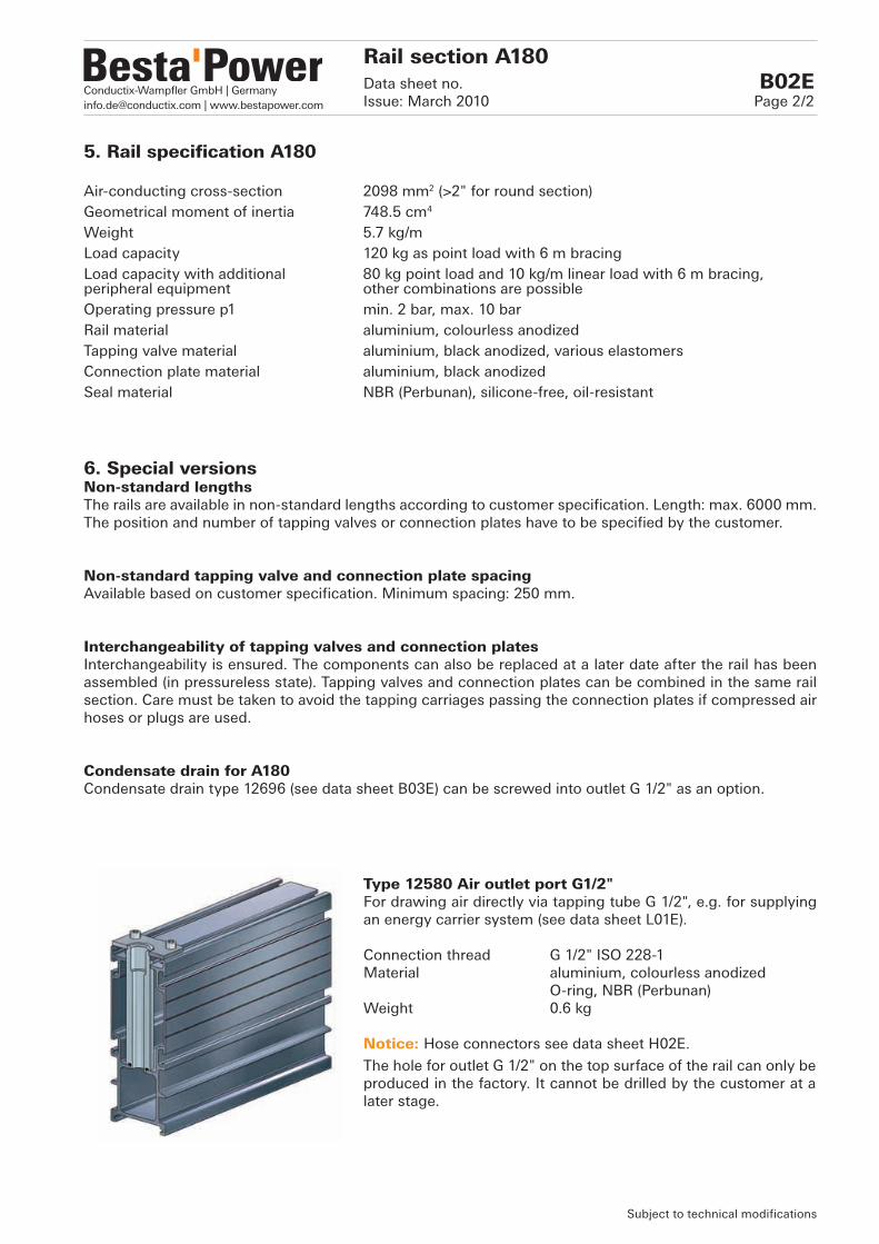
5. Rail specification A180
Air-conducting cross-section 2098 mm2 (>2" for round section)Geometrical moment of inertia 748.5 cm4
Weight 5.7 kg/mLoad capacity 120 kg as point load with 6 m bracingLoad capacity with additional 80 kg point load and 10 kg/m linear load with 6 m bracing,peripheral equipment other combinations are possibleOperating pressure p1 min. 2 bar, max. 10 barRail material aluminium, colourless anodizedTapping valve material aluminium, black anodized, various elastomersConnection plate material aluminium, black anodizedSeal material NBR (Perbunan), silicone-free, oil-resistant
Type 12580 Air outlet port G1/2"For drawing air directly via tapping tube G 1/2", e.g. for supplying an energy carrier system (see data sheet L01E).
Connection thread G 1/2" ISO 228-1Material aluminium, colourless anodized O-ring, NBR (Perbunan) Weight 0.6 kg
Notice: Hose connectors see data sheet H02E.
The hole for outlet G 1/2" on the top surface of the rail can only be produced in the factory. It cannot be drilled by the customer at a later stage.
6. Special versionsNon-standard lengthsThe rails are available in non-standard lengths according to customer specification. Length: max. 6000 mm. The position and number of tapping valves or connection plates have to be specified by the customer.
Non-standard tapping valve and connection plate spacingAvailable based on customer specification. Minimum spacing: 250 mm.
Interchangeability of tapping valves and connection platesInterchangeability is ensured. The components can also be replaced at a later date after the rail has been assembled (in pressureless state). Tapping valves and connection plates can be combined in the same rail section. Care must be taken to avoid the tapping carriages passing the connection plates if compressed air hoses or plugs are used.
Condensate drain for A180Condensate drain type 12696 (see data sheet B03E) can be screwed into outlet G 1/2" as an option.
Conductix-Wampfler GmbH | [email protected] | www.bestapower.com
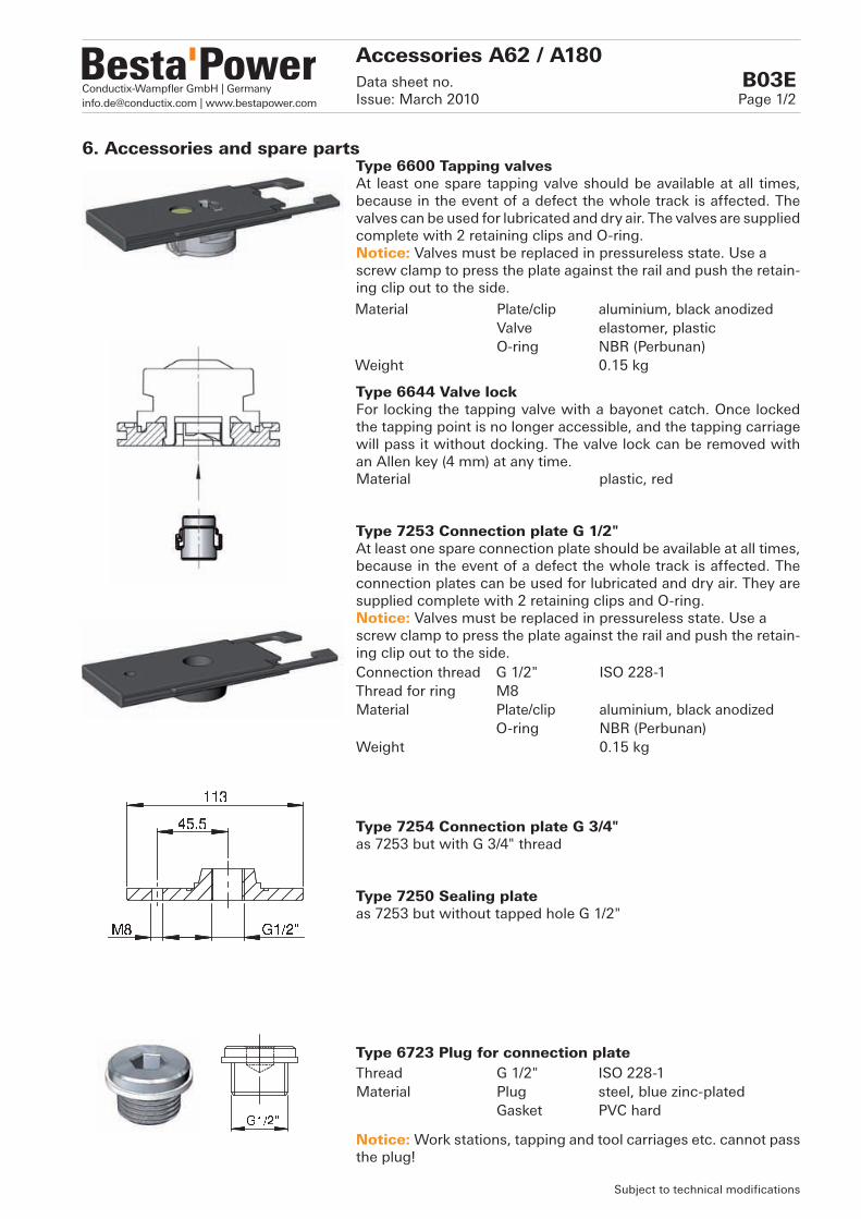
6. Accessories and spare partsType 6600 Tapping valvesAt least one spare tapping valve should be available at all times, because in the event of a defect the whole track is affected. The valves can be used for lubricated and dry air. The valves are supplied complete with 2 retaining clips and O-ring.Notice: Valves must be replaced in pressureless state. Use ascrew clamp to press the plate against the rail and push the retain-ing clip out to the side.
Type 6644 Valve lockFor locking the tapping valve with a bayonet catch. Once locked the tapping point is no longer accessible, and the tapping carriage will pass it without docking. The valve lock can be removed with an Allen key (4 mm) at any time.Material plastic, red
Type 7253 Connection plate G 1/2"At least one spare connection plate should be available at all times, because in the event of a defect the whole track is affected. The connection plates can be used for lubricated and dry air. They are supplied complete with 2 retaining clips and O-ring.Notice: Valves must be replaced in pressureless state. Use ascrew clamp to press the plate against the rail and push the retain-ing clip out to the side.
Type 7254 Connection plate G 3/4"as 7253 but with G 3/4" thread
Type 7250 Sealing plate as 7253 but without tapped hole G 1/2"
Type 6723 Plug for connection plate
Notice: Work stations, tapping and tool carriages etc. cannot pass the plug!
Subject to technical modifications
Accessories A62 / A180Data sheet no. B03EIssue: March 2010 Page 1/2
Material Plate/clip aluminium, black anodizedValve elastomer, plasticO-ring NBR (Perbunan)
Weight 0.15 kg
Connection thread G 1/2" ISO 228-1Thread for ring M8Material Plate/clip aluminium, black anodized
O-ring NBR (Perbunan)Weight 0.15 kg
Thread G 1/2" ISO 228-1Material Plug steel, blue zinc-plated
Gasket PVC hard

Conductix-Wampfler GmbH | [email protected] | www.bestapower.com
Subject to technical modifications
Accessories A62 / A180Data sheet no. B03EIssue: March 2010 Page 2/2
Type 6623 Rail end stopCan be screwed to any end piece as limit stop for tapping and tool carriages, work stations etc.
Each end piece (see data sheet D01E) is supplied with a rail end stop.
Type 7270 Plug for A62The plugs can be used to seal unused holes(25 mm dia.) on the top surface of A62 rail sections.
Type 7275 Condensate drain for A62An optional condensate drain can be installed on the top surface of A62 rail sections, see data sheet B01E, page 2. Drain hose (in-side diameter: 4 mm) and vent valve are not part of our scope of delivery.Weight, material see plug type 7270.
Type 12696 Condensate drain for A180See data sheet B02E, page 2.
Type 6860 Fixed tapping point A62, G 1"The fixed tapping point can be used as inlet or outlet, e.g. for station-ary consumers. It can be installed anywhere on the top surface of the A62 rail sections by two screws, although preferably not directly above tapping valves or connection plates. Tapping and tool car-riages, work stations etc. can pass the fixed tapping point without problem. (see assembly instructions LPI01Z and LPP13Z).
Material elastomer, NBR (Perbunan)Weight 0.15 kg
Material Plug aluminium, red anodizedPlate steel, black zinc-platedO-ring NBR (Perbunan)
Weight 0.1 kg
Connection thread G 1" ISO 228-1Sealing surface for flat seal, DIN 3852Material aluminium, colorless anodizedWeight 0.25 kg

Conductix-Wampfler GmbH | [email protected] | www.bestapower.com
Curved rails can be combined with straight rail pieces as required. The rail coupling and the pre-assem-bled flange (see page 2) are used for this purpose. Curved rails enable configuration of continuous ring lines. To increase stability and reduce wear they are made from steel. If a tapping point is required, it can be configured using a straight rail section with a minimum length of 276 mm (type 6993.1) between the two curved segments.Curved rails are available with or without air feed-through (1" hose). (See page 2)
45° bend 90° bend, assembled from 2 x 45°
* fastening point, thread M10 right-handed
1. Curved railsTable 1
Without air feed-through 7202With air feed-through (max. 10 bar) 7202.1
Radius R mm 1000Angle ° 45Weight kg 4.5Rail material steel, QPQ treated, blackRail flange material aluminium, black anodized, various elastomersSeal material O-rings: NBR (Perbunan), silicone-free
Curved rail sections Data sheet no. B04EIssue: March 2010 Page 1/2
Subject to technical modifications

Conductix-Wampfler GmbH | [email protected] | www.bestapower.com
2. External air feed-throughThe straight rail segments separated by the curved rail (with/without air feed-through) may by supplied externally using the following installation types:
1 Inlet coupling with G 1 1/4" connection A62 (type 12510) A180 (type 12530)
2 1/2" outlet or fixed tapping point G 1" A62 (type 6850, 6720)
3 Feeding of both segments via end piece G 1 1/4" A62/180 (type 12550)
Rail endWithout air feed-through
Section viewWithout air feed-through With air feed-through
With air feed-through
Curved rail sectionsData sheet no. B04EIssue: March 2010 Page 2/2
Type 6607 Rail couplingSimple rail connector for connecting curved rail sections with straight rail sections A62 / A180.Material aluminium, black anodizedWeight 0.4 kg
Type 6114.1 Rail flange, completeThe rail flange is required for attaching the coupling to the straight rail section A62 / A180. Material aluminium, black anodizedWeight 0.4 kg
Subject to technical modifications
right right
3. Options and Notice 90° bend90° bends are assembled from two 45° bends and a rail coupling (type 6607) (no separate article number).
Mounting In 90° bends the curved pieces should additionally be suspended at the centre of the curve for stability reasons (see page 1, fastening point). A threaded nut M10, right handed, is welded into the curved rail.

Conductix-Wampfler GmbH | [email protected] | www.bestapower.com
60
60
60
Type 12500 Coupling A62Standard rail coupling, to connect any type of straight or rail.Material aluminium, colourless anodized Weight 0.3 kg
Type 12510 Inlet coupling A62 with lateral connection G 1 1/4"Coupling with lateral air connection as inlet or outlet, e.g. for sta-tionary air consumers.Lateral connection thread G 1 1/4" ISO 228-1Sealing face, connection thread for flat seals, DIN 3852Material Coupling aluminium, colourless anodized Lat. conn. aluminium, black anodizedWeight 1.2 kg
Type 12511 Inlet coupling A62with vertical connection G 1"Coupling as Type 12510, but with vertical air connection G 1" as inlet or outlet, e.g. for stationary air consumers.Vertical connection thread G 1" ISO 228-1 Sealing face, connection thread for flat seals, DIN 3852Material aluminium, colourless anodized Weight 0.8 kg
Type 12512 Coupling A62 with ball valveCoupling with ball valve to isolate rail sections. Manually operated from the rail underside.Material Coupling aluminium, colourless anodized Valve plastic, chrome-plated brass Weight 0.8 kg
Rail connections A62Data sheet no. C01EIssue: March 2010 Page 1/2
Subject to technical modifications
1. Rail couplings A62
The rail couplings serve as connection elements for rail sections, type A62. They are screwed directly to the rail section and sealed with O-rings. All coupling types are interchangeable and can be passed by tapping and tool car-riages, work stations, etc. The length of coupling type 12500 has no influence on the overall length of the installation. Only the lengths of the rail sections are to be added.If an inlet coupling or a coupling with ball valve is used, the overall length of the installation increases by 60 mm per coupling piece.

Conductix-Wampfler GmbH | [email protected] | www.bestapower.com
60
60
Subject to technical modifications
Rail Connections A62Data sheet no. C01EIssue: March 2010 Page 2/2
Type 12513 Inlet coupling A62 with ball valve and lateral connection G 1 1/4"Combination of coupling types 12510 and 12512. This coupling enables isolation of one of the two rail sections, but not both at the same time.Lateral connection thread G 1 1/4" ISO 228-1Sealing face, connection thread for flat seals, DIN 3852Material Coupling aluminium, colourless anodized Lat. conn. aluminium, black anodized Valve plastic, chrome-plated brassWeight 1.3 kg
Type 12514 Inlet coupling A62with ball valve and vertical connection G 1"Combination of coupling types 12511 and 12512. This coupling enables isolation of one of the two rail sections, but not both at the same time.Vertical connection thread G 1" ISO 228-1Sealing face, connection thread for flat seals, DIN 3852Material Coupling aluminium, colourless anodized Valve plastic, chrome-plated brassWeight 0.9 kg
2. NoticeFilter, shut-off valveIf the rail couplings are used as an air inlet an appropriate air filter (minimum 30-40 µm) should be fitted before the inlet in order to prevent contamination of the rail section. If non-corrosive piping is used between a decentralized filter station and the Bestapower system, an additional filter at the air inlet is generally not necessary. Depending on the installation and layout of the supply piping it is advisable to have a flexible arrangement between pipework and Bestapower inlet (e.g. with a hose). The Bestapower system does not generate any contamination.The installation of a shut-off valve at the air inlet(s) is recommended, but the requirement entirely depends on the layout of the supply line.
Bestapower means:clean air in - clean air out! Clean compressed air extends the service life of your tools!
Stationary compressed air consumersIn order not to limit the flexibility of the tapping and tool carriages unnecessarily, we recommend supplying stationary compressed air consumers (e.g. handling units, machines) through rail couplings with lateral or vertical connection. If the position of the coupling is not convenient, the fixed tapping point type 6720 (see data sheet B03E) can be used as an alternative.
SuspensionHangers (see data sheet E01E) should be placed near a coupling piece to guarantee optimum sealing between coupling and rail.
Curved rail sectionsA rail flange type 6114.1 and a rail coupling type 6607 (see data sheet B04E) are required for connecting curved rail sections with the rail section.

Conductix-Wampfler GmbH | [email protected] | www.bestapower.com
60
60
Type 12501 Coupling A180Simple coupling with connection plate for connecting any type of straight rail.Material aluminium, colourless anodized Weight 0.5 kg
Type 12530 Inlet coupling A180 with vertical G 1 1/4" connectionCoupling with vertical connection as inlet or outlet, e.g. for station-ary air consumers. Vertical connection thread G 1 1/4" ISO 228-1 Sealing face, connection thread for flat seals, DIN 3852Material aluminium, colourless anodized Weight 1.9 kg
Type 12531 Inlet coupling A180 with ball valve and vertical connection G 1 1/4" Coupling as type 12530, but with additional ball valve, to isolate rail sections. Manually operated from the rail underside. Vertical connection thread G 1 1/4" ISO 228-1Sealing face, connection thread for flat seals, DIN 3852Material Coupling aluminium, colourless anodized Valve plastic, chrome-plated brass Weight 2.0 kg
Rail connections A180Data sheet no. C02EIssue: March 2010 Page 1/2
1. Rail couplings A180
Subject to technical modifications
The rail couplings serve as connection elements for rail sections, type A180. They are screwed directly to the rail section and sealed with O-rings. All coupling types are interchangeable and can be passed by tapping and tool carriages, work stations, etc. The length of coupling type 12501 has no influence on the overall length of the installation. Only the lengths of the rail sections are to be added.If an inlet coupling is used, the overall length of the installation increases by 60 mm per coupling piece.

Conductix-Wampfler GmbH | [email protected] | www.bestapower.com
2. NoticeFilter, shut-off valveIf the rail couplings are used as an air inlet an appropriate air filter (minimum 30-40 µm) should be fitted before the inlet in order to prevent contamination of the rail section. If non-corrosive piping is used between a decentralized filter station and the Bestapower system, an additional filter at the air inlet is generally not necessary. Depending on the installation and layout of the supply piping it is advisable to have a flexible arrangement between pipework and Bestapower inlet (e.g. with a hose). The Bestapower system does not generate any contamination.The installation of a shut-off valve at the air inlet(s) is recommended, but the requirement entirely depends on the layout of the supply line.
Bestapower means:clean air in - clean air out! Clean compressed air extends the service life of your tools!
Stationary compressed air consumersIn order not to limit the flexibility of the tapping and tool carriages unnecessarily, we recommend supplying stationary compressed air consumers (e.g. handling units, machines) through rail couplings with vertical connection.
SuspensionWhenever possible, hangers (see data sheet E02E) should be placed near a coupling piece to guarantee optimum sealing between coupling and rail.
Curved rail sectionsA rail flange type 6114.1 and a rail coupling type 6607 (see data sheet B04E) is required for connecting curved rail sections with the rail section. The load limit of the curved rail sections is lower than that of rail section A180. The suspension must be designed accordingly.
Subject to technical modifications
Rail connections A180Data sheet no. C02EIssue: March 2010 Page 2/2

Conductix-Wampfler GmbH | [email protected] | www.bestapower.com
1. End piece with G 1 1/4"
The end pieces serve as rail termination or as axial air inlet. They are screwed to the face of the rail section and sealed with O-rings. Each rail termination is supplied with a rail end stop as limit stop for tapping and tool carriages, work stations etc.
Type 12550 End piece G 1 1/4" and end stopAxial air inlet for all straight rail sectionsConnection thread G 1 1/4" ISO 228-1Sealing face, connection thread for flat seals, DIN 3852Material Termination aluminium, colourless anodized End stop elastomer, NBR (Perbunan)Weight 0.4 kg
Type 12551 End piece, blind, and end stopRail termination for all straight rail sectionsMaterial Termination aluminium, colourless anodized End stop elastomer, NBR (Perbunan)Weight 0.6 kg
Type 12620 Cover plate A180As termination of the upper profile openingConnection 2 sliding blocks M6Material aluminium, colourless anodized Weight 0.1 kg
2. End piece, blind
End pieces A62 / A180Data sheet no. D01EIssue: March 2010 Page 1/2
3. Cover plate A180
Subject to technical modifications

Conductix-Wampfler GmbH | [email protected] | www.bestapower.com
4. NoticeAxial air inletConnection pieces must either have a parallel pipe thread (ISO 228-1) with a flat seal or a taper thread (ISO 7-1). Taper threads must be sealed with sealing fluid. NPT threads must not be used.
Filter, shut-off valveIf the rail couplings are used as an air inlet an appropriate air filter (minimum 30-40 µm) should be fitted before the inlet in order to prevent contamination of the rail section. If non-corrosive piping is used between a decentralized filter station and the Bestapower system, an additional filter at the air inlet is generally not necessary. Depending on the installation and layout of the supply piping it is advisable to have a flexible arrangement between pipework and Bestapower inlet (e.g. with a hose). The Bestapower system does not generate any contamination.The installation of a shut-off valve at the air inlet(s) is recommended, but the requirement entirely depends on the layout of the supply line.
Bestapower means: clean air in - clean air out! Clean compressed air extends the service life of your tools!
End stopTo avoid tapping and tool carriages, work stations etc. sliding off the rail, the rail end stop as supplied must be fitted.
Subject to technical modifications
End pieces A62 / A180Data sheet no. D01EIssue: March 2010 Page 2/2

Conductix-Wampfler GmbH | [email protected] | www.bestapower.com
In order to allow linear thermal expansion of the aluminium rails two different hangers are available. The fixed point hanger (red) must only be used once per track, preferably next to the inlet. It fixes the rail in all three planes.The sliding hanger (black) is used for all other suspension points and allows linear expansion of the track. Depending on the attached load, the spacing between the suspension points is approx. 2 to 3 m.Whenever possible, one hanger should always be positioned close to the rail connector (see page 2). Notice: Torque for hangers: approx. 7 Nm ( 10).
1. Hanger
Fixed point hanger Type 6624 Type 6625Fastening nut M10 RH M10 LH
yellow passivated blue passivatedColour red redMaterial polyamide 6.6 polyamide 6.6Weight 0.1 kg 0.1 kg
Sliding hanger Type 6626 Type 6627Fastening nut M10 RH M10 LH
yellow passivated blue passivatedColour black blackMaterial polyamide 6.6 polyamide 6.6Weight 0.1 kg 0.1 kg
2. Bolt sets
Type 6628 Threaded bolt setRH parts yellow passivatedThread M10 RHTo fit hangers Type 6624 / 6626 (M10 RH)Weight 0.1 kg
Type 6629 Turnbuckle half setLH parts blue passivatedThread M10 LHTo fit hangers Type 6625 / 6627 (M10 LH)Weight 0.2 kg
Type 6630 Turnbuckle setRH parts LH parts
yellow passivatedblue passivated
Thread M10 LH / RHTo fit hangers Type 6625 / 6627 (M10 LH)Weight 0.3 kg
Rail mounting A62Data sheet no. E01EIssue: March 2010 Page 1/2
Subject to technical modifications
Notice: In combination with turnbuckle set type 6630, hangers with
LH thread, type 6625/6627 must be used.
M10 right
M10 right
M10 right
M10 left
M10 left
M10 right
M10 left
M10 left
Conductix-Wampfler GmbH | [email protected] | www.bestapower.com
3. NoticeBolt setsInstead of the bolt sets listed on the front page, other components, e.g. threaded bars M10, supplied by the customer, may be used.
4. Mounting of additional componentsThe fixed point hangers can also be used to mount additional components such as energy carrier systems, conductor rails (see data sheets L01E, M01E), lamps etc.
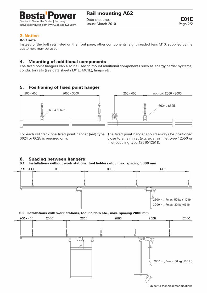
For each rail track one fixed point hanger (red) type 6624 or 6625 is required only.
The fixed point hanger should always be positioned close to an air inlet (e.g. axial air inlet type 12550 or inlet coupling type 12510/12511).
6. Spacing between hangers6.1. Installations without work stations, tool holders etc., max. spacing 3000 mm
6.2. Installations with work stations, tool holders etc., max. spacing 2000 mm
Subject to technical modifications
2500 = ↓ Fmax. 50 kg (110 lb)
3000 = ↓ Fmax. 30 kg (66 lb)
2000 = ↓ Fmax. 80 kg (180 lb)
5. Positioning of fixed point hanger
Rail mounting A62Data sheet no. E01EIssue: March 2010 Page 2/2
approx.

Conductix-Wampfler GmbH | [email protected] | www.bestapower.com
Various fastening options are available for securing the rail mounting, type A180, at the steel structure of the hall. The mounting plate is suitable for a wide range of standard beams in conjunction with common mounting rails. In order to allow linear thermal expansion of the rails, sliding mounting plates should be used. The fixed mounting plate must be used once per rail track only, preferably next to the inlet. Girder clamps can be used if necessary.If cable suspension is required, this can be realized with cable mounting elements and fixed sliding blocks.Due to the high load carrying capability the maximum spacing between fasteners is 6 m for 120 kg point load or 80 kg with 10 kg/m linear load.
1. Mounting plateType 12641 Mounting plate, fixedSliding block, fixed Type 12611, 2 xMaterial steel, blue zinc-platedWeight 1.4 kg
Type 12642 Sliding mounting plate Sliding block (black) Type 12613, 2 xMaterial steel, blue zinc-platedWeight 1.4 kg
1.1 Clamping sets
Rail mounting A180Data sheet no. E02EIssue: March 2010 Page 1/2
Subject to technical modifications
Type 12650 Clamping set 300/150Suitable for beams up to 150 mm wide.Threaded rod 2 x, M10x300Mounting rail 2 x, length 250 mmMaterial steel, blue zinc-platedWeight 1.4 kg
Type 12651 Clamping set 300/90Suitable for beams up to 90 mm wide.Threaded rod 2 x, M10x300Mounting rail 2 x, length 185 mmMaterial steel, blue zinc-platedWeight 1.2 kg
Type 12652 Clamping set 200/90Suitable for beams up to 90 mm wide (with shorter threaded rod).Threaded rod 2 x, M10x200Mounting rail 2 x, length 185 mmMaterial steel, blue zinc-platedWeight 1.0 kg

Conductix-Wampfler GmbH | [email protected] | www.bestapower.com
244
244
420
4.3 Shear forcesThreaded rods can be used for lateral stabilization of the track and for absorbing shear forces. The rods should preferably be installed at the start and the end, and every 24 to 30 metres.
5. Fastening of additional elementsThe A180 section can also be used to mount additional elements such as energy carrier systems, conductor rails (see data sheet L01E, M01E), cable ducts, lamps etc.
Subject to technical modifications
Rail mounting A180Data sheet no. E02EIssue: March 2010 Page 2/2
2. Cable mountingCable mounting is a further option for suspending the A180 section from the steel structure of the hall. The cable sets are not part of the scope of supply and have to be provided by the customer.
Type 12640 Cable mountingSliding block, fixed Type 12611, 2 xMaterial steel, blue zinc-platedWeight 1.5 kg
3. Fastening angle The fastening angle can be used to mount peripheral elements such as lamps at the A180 section. The fasteners for the peripheral elements are not part of the scope of supply.
Type 12632 Fastening angleSliding block swivelling, 2 xMaterial steel, blue zinc-platedWeight 0.8 kg
4. Suspension4.1 Mounting example with mounting plate and clamping setDue to the high load carrying capability of the A180 section the fasteners can be placed anywhere within the 6 m spacing.
↓ Fmax. 120 kg (264 lb) for point load
↓ Fmax. 80 kg (176 lb) and 10 kg/m linear load
4.2 Mounting example with cable mountingDue to the high load carrying capability of the A180 section the fasteners can be placed anywhere within the 6 m spacing.
↓ Fmax. 120 kg (264 lb) for point load
↓ Fmax. 80 kg (176 lb) and 10 kg/m linear load

Conductix-Wampfler GmbH | [email protected] | www.bestapower.com
1. Four basic tapping carriage types1. without arrangement for FRL units2. with arrangement for 3/8" FRL units3. with attached 1/2" FRL units4. with attached injection lubricator
FRL: F = Filter, R = Regulator, L = Lubricator
2. Basic equipment for carriage types 1 to 4- Hook to fix spring retainer or balancer.- Connection thread G 1/4" for pressure gauge, underside of
carriage.- Fixing slots to accommodate buffer, detaching device or carriage
coupling.- Connection thread for hose set (NW 3/8", 1/2").
3. Tapping carriages without arrangement for FRL units. Type 8670
The low cost type tapping carriage for all applications where air prepa-ration and/or regulation is not required. The carriage can be used for a pressure range of min. 2 bar to max. 10 bar and is regarded economical for flow rates up to approx. 1500 Nl/min, max. approx. 2000 Nl/min.Detailed description see data sheet F02E.
4. Tapping carriages with arrangement to attach 3/8" FRL units. Type 8614Depending on the requirement, 3/8" tapping carriages can be equipped with 1 or 2 FRL components, which allow individual air preparation and/or regulation near the air consumer.Because of the integrated check valves, these carriages can also be operated without any FRL units attached. Hence, FRL components can also be fitted at a later date. The carriage can be used for a pres-sure range of min. 2 bar to max. 10 bar and is regarded as economical for flow rates up to 850 Nl/min., max. approx. 1200 Nl/min.Detailed description see data sheet F03E.
Subject to technical modifications
Tapping carriages are ideal for applica-tions where the air consumer is moving, i.e. not stationary. The operating range of the tapping car-riages is only limited by the length of the installation or other workstations / tapping carriages. All tapping carriages can be used for lubricated or dry air. They are used in combination with rails with integrated tapping valves (data sheets B01E and B02E / Table 1).All components used are silicone-free.
Tapping carriagesData sheet no. F01EIssue: March 2010 Page 1/2

Conductix-Wampfler GmbH | [email protected] | www.bestapower.com
7. Track rollersAll tapping carriages are supplied with steel track rollers as standard (roller bearing with specially ground radius). As an option track rollers with a PUR coating are available. PUR wheels are useful in case of special requirements with regard to smooth operation. Part numbers with suffix for PUR wheels: e.g. 8614 >> 8614-PUR.
8. Detailed descriptionTapping carriages without FRL units data sheet F02E3/8" tapping carriages with FRL units data sheet F03E3/8" FRL units, assembly kit data sheet F03E1/2" tapping carriages with FRL units data sheet F04ETapping carriages with injection lubricator data sheet F05EHose set and spare parts data sheet F10EDetaching devices data sheet G01ETool carriages data sheets H01E, H02ELoad carriers, cable trolleys data sheet I01EWork stations data sheets K01E, K02ETool holders data sheets K03E, K04E
Subject to technical modifications
Tapping carriagesData sheet no. F01EIssue: March 2010 Page 2/2
6. Tapping carriages with attached 1/2" injection lubricator. Type 8714A
5. Tapping carriages with attached 1/2" FRL units. Types 8702.1, 8702.2, 8702.3, 8702.4, 8702.8, 8702.9
1/2" carriages are recommended for use whenever the flow rate is above the economical volume for the 3/8" carriages. These 1/2" carriages are not operative without a FRL component attached. The carriage can be used for a pressure range of min. 2 bar to max. 10 bar and is regarded as economical for flow rates up to 1500 Nl/min., max. approx. 2000 Nl/min.Detailed description see data sheet F04E.
This 1/2" tapping carriage allows adjustable oil injection. The oil is either injected at the hose inlet, or, if a coaxial oil tube in the air hose is used, directly before the consumer/tool.Detailed description see data sheet F05E.

Conductix-Wampfler GmbH | [email protected] | www.bestapower.com
Type 8670 Tapping carriageOperating pressure p1 min. 2 bar, max. 10 barFlow rate Q see data sheet S01E at 6 bar, approx. 2000 Nl/min. economical 1500 Nl/min.Max. load on hook approx. 20 kgMaterial aluminium, various plastic materialsWeight 1.8 kg
Subject to technical modifications
Tapping carriage without FRLData sheet no. F02EIssue: March 2010 Page 1/2
1. Basic equipment- Hook to fix spring retainer or bal-
ancer.
- Connection thread G 1/4" for pres-sure gauge, underside of carriage.
- Fixing slots to accommodate buffer, detaching device or car-riage coupling.
- Connection thread for hose set (NW 3/8", 1/2").
2. Tapping carriages without arrangement for FRL units Low cost tapping carriage for all applications where air preparation and/or regulation is not required. Since the use of a filter at each rail inlet is required, additional filtration on the tapping carriage is not necessary for most applications.These tapping carriages are characterised by simple functional design and high flow rate.
3. AccessoriesThe tapping carriages are equipped to accommodate the following parts:
Hose set required for smooth operation data sheet F10E of the tapping carriages
Buffer, pressure gauge can be attached if required; data sheet F10E buffers protect the carriages against collision forces
Detaching devices can be attached if required data sheet G01E
Tool carriages can be attached if required data sheets H01E, H02E
Load carriers can be attached if required data sheet I01E
All tapping carriages can be combined with work stations or tool holders, see data sheets K02E-K04E.

Conductix-Wampfler GmbH | [email protected] | www.bestapower.com
Type 6229 Reducer M36-G 1/2" external threadThe reducer (complete with O-ring and two spacers) can be fitted to the tapping carriage instead of tube nut type 6639 and allows connection of an air fuse or a regulator, for example. Connection thread for carriage M36x1.5Connection thread for accessory G 1/2" ISO 228-1Materials Reducer aluminium, blue anodized Spacers aluminium, colourless anodized O-rings NBR (Perbunan)Weight 0.1 kg
Type 6292 Reducer M36-G 1/2" internal threadThe reducer (complete with O-ring and two spacers) can be fitted to the tapping carriage instead of tube nut type 6639 and allows connection of a hose (other than Parker push-lock).Connection thread for carriage M36x1.5Connection thread for accessory G 1/2" ISO 228-1Materials: Reducer aluminium, blue anodized Spacers aluminium, colourless anodized O-rings NBR (Perbunan)Weight: 0.1 kg
Type 6293 Reducer M36-G 3/4" internal thread(as 6292, but with G 3/4" thread)
Type 6717 Air fuse 3/8"Type 6718 Air fuse 1/2"The air fuse is an automatic shut-off valve with automatic reset and fixed setting. It prevents uncontrolled escape of air in the event of a burst hose. If the flow exceeds a certain value (e.g. in the event of a burst hose), the valve closes and remains until the pressure has equalized again.Notice: The minimum pressure directly depends on the hoselength. For further details please contact us.
Materials: Body aluminium Valve brass Spring stainless steel
If no detaching device is used, the air fuse can be fit-ted directly to the tapping carriage, e.g. with a reducer type 6229 (example 1). If a detaching device is used the air fuse must be fitted below the detaching device (example 2).
Example 1
Subject to technical modifications
Type Norgren no.
A (mm) B (mm) C Residual closing pressure (bar)
Closing flow (l/s) 1)
Flow rate(l/s) 1)
Weight kg
6717 T60C3890 24 62 G 3/8" 0.14 19.4 13.5 0.0656718 T60C4890 31.75 78 G 1/2" 0.14 32.2 23.2 0.15
Tapping carriage without FRLData sheet no. F02EIssue: March 2010 Page 2/2
4. Special accessories for tapping carriage
1) at 7 bar primary pressure
Example 2
Conductix-Wampfler GmbH | [email protected] | www.bestapower.com
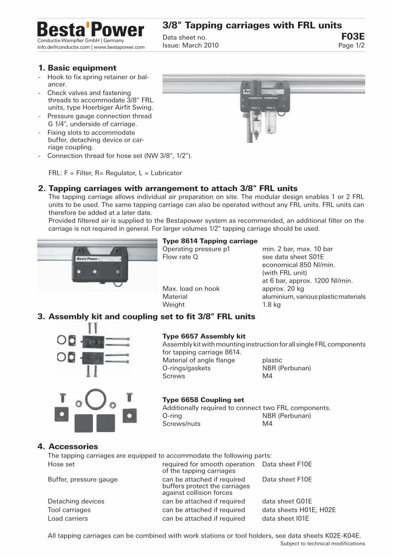
Type 8614 Tapping carriageOperating pressure p1 min. 2 bar, max. 10 barFlow rate Q see data sheet S01E economical 850 Nl/min. (with FRL unit) at 6 bar, approx. 1200 Nl/min. Max. load on hook approx. 20 kgMaterial aluminium, various plastic materials Weight 1.8 kg
Type 6657 Assembly kitAssembly kit with mounting instruction for all single FRL components for tapping carriage 8614.Material of angle flange plasticO-rings/gaskets NBR (Perbunan)Screws M4
Type 6658 Coupling setAdditionally required to connect two FRL components.O-ring NBR (Perbunan)Screws/nuts M4
3. Assembly kit and coupling set to fit 3/8" FRL units
4. AccessoriesThe tapping carriages are equipped to accommodate the following parts:Hose set required for smooth operation Data sheet F10E of the tapping carriages Buffer, pressure gauge can be attached if required Data sheet F10E buffers protect the carriages against collision forcesDetaching devices can be attached if required data sheet G01ETool carriages can be attached if required data sheets H01E, H02ELoad carriers can be attached if required data sheet I01E
All tapping carriages can be combined with work stations or tool holders, see data sheets K02E-K04E.
3/8" Tapping carriages with FRL unitsData sheet no. F03EIssue: March 2010 Page 1/2
Subject to technical modifications
1. Basic equipment- Hook to fix spring retainer or bal-
ancer.- Check valves and fastening
threads to accommodate 3/8" FRL units, type Hoerbiger Airfit Swing.
- Pressure gauge connection thread G 1/4", underside of carriage.
- Fixing slots to accommodate buffer, detaching device or car-riage coupling.
- Connection thread for hose set (NW 3/8", 1/2").
FRL: F = Filter, R= Regulator, L = Lubricator
2. Tapping carriages with arrangement to attach 3/8" FRL unitsThe tapping carriage allows individual air preparation on site. The modular design enables 1 or 2 FRL units to be used. The same tapping carriage can also be operated without any FRL units. FRL units can therefore be added at a later date.Provided filtered air is supplied to the Bestapower system as recommended, an additional filter on the carriage is not required in general. For larger volumes 1/2" tapping carriage should be used.

Conductix-Wampfler GmbH | [email protected] | www.bestapower.com
Type 6616A Filter/regulator combination unit 3/8", SK-3/8-BPOperating pressure inlet p1 min. 2 bar, max. 10 barOperating pressure outlet p2 max. 8 barFilter element (white) 30 µm (5 µm possible, yellow) Filter efficiency 90 %Flow rate see data sheet S01EWeight 0.35 kg
Type 6617A Filter 3/8", SF-3/8-BPOperating pressure inlet p1 min. 2 bar, max. 10 barFilter element (white) 30 µm (5 µm possible, yellow)Filter efficiency 90 %Flow rate see data sheet S01EWeight 0.25 kg
Type 6618A Regulator 3/8", SR-3/8-BPOperating pressure inlet p1 min. 2 bar, max. 10 barOperating pressure outlet p2 max. 8 barFlow rate see data sheet S01EWeight 0.30 kgOption: Pressure gauge type 7411 with
G 1/8" connection, for direct installation at 3/8" regulator
Type 6619A Mist lubricator 3/8", SL-3/8-BPOperating pressure inlet p1 min. 2 bar, max. 10 barOil capacity max. 45 cm3
Flow rate see data sheet S01EWeight 0.35 kg
7. Type with bowl guardAll F+L units with a plastic bowl can also be supplied with a metal bowl guard. Part numbers with suffix US, e.g. 6616A >> 6616AUS.Retrofitting is possible.
Subject to technical modifications
Filter/regulator with Filter and regulator Regulator and mist Filter and mist mist lubricator lubricator lubricator
3/8" Tapping carriages with FRL unitsData sheet no. F03EIssue: March 2010 Page 2/2
5. 3/8" Service units (Hoerbiger Airfit Swing) for tapping carriage type 8614
6. Combination of service units

Conductix-Wampfler GmbH | [email protected] | www.bestapower.com
Type 8702.1 Tapping carriage with 1/2" filter/regulator combination unit, CK-1/2-BPOperating pressure inlet p1 min. 2 bar, max. 10 barOperating pressure outlet p2 max. 8 barFlow rate Q see data sheet S01E at 6 bar, approx. 2000 Nl/min.* Filter element (white) 30 µm (5 µm possible)Filter efficiency 95 %Max. load on hook approx. 20 kgTapping carriage material aluminium, plasticsWeight 2.7 kg
Type 8702.2 Tapping carriage with 1/2" filter, CF-1/2-BP Operating pressure inlet p1 min. 2 bar, max. 10 barFlow rate Q see data sheet S01E at 6 bar, approx. 2000 Nl/min.* Filter element (white) 30 µm (5 µm possible)Filter efficiency 95 %Max. load on hook approx. 20 kgTapping carriage material aluminium, plasticsWeight 2.3 kg
Type 8702.3 Tapping carriage with 1/2" regulator, CR-1/2-BP Operating pressure inlet p1 min. 2 bar, max. 10 barOperating pressure outlet p2 max. 8 barFlow rate Q see data sheet S01E at 6 bar, approx. 2000 Nl/min.* Max. load on hook approx. 20 kgTapping carriage material aluminium, plasticsWeight 2.4 kg
Option: Pressure gauge type 7411.2 with G 1/4"Connection for direct installation at regulator 1/2"
Tapping carriages with 1/2" FRL unitsData sheet no. F04EIssue: March 2010 Page 1/2
* economical 1500 Nl/min. Subject to technical modifications
1. Basic equipment- Hook to fix spring retainer or
balancer.- Pressure gauge connection thread
G 1/4", underside of carriage- Fixing slots to accommodate
buffer, detaching device or carriage coupling.
- Connection thread for hose set (NW 3/8", 1/2").
FRL: F = Filter, R = Regulator, L = Lubricator
2. Tapping carriages with attached 1/2" FRL units The tapping carriage allows individual air preparation on site. The modular design enables 1 or 2 FRL
units, type Hoerbiger Airfit Comfort, to be used. Providing filtered air is supplied to the Bestapower system as recommended, an additional filter on the carriage is not required in general.
Notice: These 1/2" tapping carriages cannot be operated without FRL units attached.
Conductix-Wampfler GmbH | [email protected] | www.bestapower.com
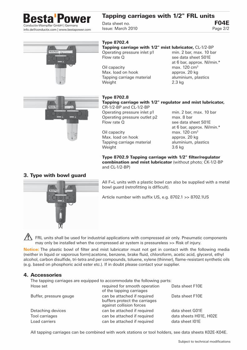
Type 8702.4Tapping carriage with 1/2" mist lubricator, CL-1/2-BPOperating pressure inlet p1 min. 2 bar, max. 10 barFlow rate Q see data sheet S01E at 6 bar, approx. Nl/min.* Oil capacity max. 120 cm3
Max. load on hook approx. 20 kgTapping carriage material aluminium, plastics Weight 2.3 kg
Type 8702.8Tapping carriage with 1/2" regulator and mist lubricator,CR-1/2-BP and CL-1/2-BP Operating pressure inlet p1 min. 2 bar, max. 10 barOperating pressure outlet p2 max. 8 barFlow rate Q see data sheet S01E at 6 bar, approx. Nl/min.* Oil capacity max. 120 cm3
Max. load on hook approx. 20 kgTapping carriage material aluminium, plastics Weight 3.6 kg
Type 8702.9 Tapping carriage with 1/2" filter/regulator combination and mist lubricator (without photo; CK-1/2-BP and CL-1/2-BP)
All F+L units with a plastic bowl can also be supplied with a metal bowl guard (retrofitting is difficult).
Article number with suffix US, e.g. 8702.1 >> 8702.1US
4. AccessoriesThe tapping carriages are equipped to accommodate the following parts:Hose set required for smooth operation Data sheet F10E of the tapping carriages Buffer, pressure gauge can be attached if required Data sheet F10E buffers protect the carriages against collision forcesDetaching devices can be attached if required data sheet G01ETool carriages can be attached if required data sheets H01E, H02ELoad carriers can be attached if required data sheet I01E
All tapping carriages can be combined with work stations or tool holders, see data sheets K02E-K04E.
3. Type with bowl guard
Subject to technical modifications
Tapping carriages with 1/2" FRL unitsData sheet no. F04EIssue: March 2010 Page 2/2
FRL units shall be used for industrial applications with compressed air only. Pneumatic components may only be installed when the compressed air system is pressureless >> Risk of injury.
Notice: The plastic bowl of filter and mist lubricator must not get in contact with the following media (neither in liquid or vaporous form): acetone, benzene, brake fluid, chloroform, acetic acid, glycerol, ethylalcohol, carbon disulfide, tri-tetra and per compounds, toluene, xylene (thinner), flame-resistant synthetic oils (e.g. based on phosphoric acid ester etc.). If in doubt please contact your supplier.

Conductix-Wampfler GmbH | [email protected] | www.bestapower.com
Type 8714A Tapping carriages with injection lubricator Operating pressure inlet p1 min. 3 bar, max. 10 bar (control medium)Flow rate Q see data sheet S01E (min. approx. 400 Nl/min.) max. approx. 2000 Nl/min.Max. load on hook approx. 20 kgTapping carriage material aluminium, plasticsWeight incl. lubricator 2.8 kgLubricant mineral oil according to DIN 51524 and 51525Viscosity 20-765 mm2/s (=cST), (=2.9-100°E)Oil feed per stroke 3-30 mm3 adjustable Feed stroke per operating pulse Reservoir capacity max. 250 cm3
Oil feed gravity feed from reservoirConnection size capillary tube dia. 2.5 / 1.5 mmfor oil tube in the control lever at the tapping carriageMaterial Lubricator aluminium housing Reservoir plastic (PETP)
2. Injection lubricator system Hoerbiger Oilfit In contrast to an oil mist lubricator, with an injection lubricator the oil can be delivered in a separate oil
tube close to the consumer. With the air flow sensor the airflow is converted into a pulsed air signal, hence the injection lubricator feeds oil per operating pulse.
3. Tapping carriage with attached 1/2" injection lubricatorThe tapping carriage with injection lubricator (Hoerbiger Oilfit System) allows precise adjustable oil injection. The oil can be atomized either:a) directly at the hose set, at the outlet of the tapping carriage, orb) directly near the consumer, by using a coaxial oil tube inside the air hose. Also for this type of tapping carriage, attention must be paid that only filtered air (min. 40 µm) is supplied to the Bestapower System. The economical flow rate is at approx. 1500 Nl/min., at 6 bar.
Notice: These 1/2" tapping carriages cannot be operated without the injection lubricator attached.
Tapping carriage with 1/2" injection lubricatorData sheet no. F05EIssue: March 2010 Page 1/2
Subject to technical modifications
1. Basic equipment- Hook to fix spring retainer or balancer.
- Pressure gauge connection thread G 1/4", underside of carriage.
- Fixing slots to accommodate buffer, detaching device or carriage coupling.
- Connection thread for hose set (NW 3/8", 1/2").

Conductix-Wampfler GmbH | [email protected] | www.bestapower.com
4. Application with or without coaxial oil tube The tapping carriage with injection lubricator can be used with or without a coaxial oil tube in the
compressed-air hose. Both methods, with or without oil tube, do have advantages and disadvantages, which should be considered for each application individually.
4.1 Application without coaxial oil tube: Due to the oil atomization directly at the outlet of the tapping carriage, i.e. just before the hose set
(straight Push-lok hose), the oil can settle on the inside of the air hose. Because of the large surface (inner tube of the hose) the air can thoroughly and continuously absorb the lubricant. In case of exces-sive lubrication, oil can collect at the lowest point of a slack hose, which can result in over-oiling of the tool.
4.2 Application with coaxial oil tube: The lubricant is supplied in the coaxial oil tube directly close to the consumer. Even if the hose is slack,
no oil will collect at the lowest point. Before the first use, the oil tube must be filled with oil. We there-fore recommend to use pre-filled oil tubes. For continuity of oil supply and the convenience of quick release and attachment of any extension air-hoses we recommend the use of quick release couplings with connecting nipple (higher pressure loss to be considered). To avoid over-oiling and draining of oil from oil line, a non-return valve should be fitted to the end of the capillary oil tube at consumer end.
On the tapping carriage, the capillary oil tube is directly fitted to a relevant nipple.
5. Coaxial oil tubeType 6719 Capillary oil tube, prefilled (for 6735)Lubricant general purpose oil (according to ISO 32)Outside diameter da 3.2 mm (0,125 in.)Inside diameter di 2.0 mm (0.080 in.)Material Nylon (flexible)Colour transparentLength per metre
Type 6735 Capillary non-return valveNipple size to suit 2.0 mm capillary oil tube (6719)Material brass housing, ball NBR
Subject to technical modifications
Tapping carriage with 1/2" injection lubricatorData sheet no. F05EIssue: March 2010 Page 2/2

Conductix-Wampfler GmbH | [email protected] | www.bestapower.com
1. Hose setConsisting of Push-lok hose (Besta standard: Parker 801, grey) with fitted nipple and complete with tube nut (O-ring and two spacers). The other hose end is free to connect the consumer. The tool can be mounted directly at the hose end or via a coupling.For a smooth undocking and docking process, a hose set of min. 300 mm length is imperative. Over this length, the movement of the hose must not be restricted. The Parker Push-lok type hose offers convenient and tight sealing between nipple and hose without additional hose clamp.
Notice: Parker Push-lok hose 801, blue is available on request.
Hose set
Notice: Hose type 801 is silicone-free. For more stringent requirements, e.g. paint processing we recommend hose type 837BM. This hose is free of any wetting disturbing substances.Further information on request.
Hose NW 1/2" (13 mm) NW 3/8" (9.5 mm)Length L (m) Type Type0.3 6615 66541.0 6615.1 6654.12.0 6615.2 6654.23.0 6615.3 6654.34.0 6615.4 6654.45.0 6615.5 6654.56.0 6615.6 6654.67.0 6615.7 6654.78.0 6615.8 6654.89.0 6615.9 6654.9
Type 6677 6678Push-lok hose NW 1/2" NW 3/8"Material steel, QPQ treated, blackWeight 0.05 kg
Tapping carriage accessoriesData sheet no. F10EIssue: March 2010 Page 1/2
Subject to technical modifications
2. Spare parts for hose setPush-lok hose (Parker 801, grey)
Hose NW 1/2" (13 mm) NW 3/8" (9.5 mm)Length L (m) Type Type0.3 6641 66421.0 6641.1 6642.12.0 6641.2 6642.23.0 6641.3 6642.34.0 6641.4 6642.45.0 6641.5 6642.56.0 6641.6 6642.67.0 6641.7 6642.78.0 6641.8 6642.89.0 6641.9 6642.9Weight 0.19 kg/m 0.41 kg/m
NippleJoins Push-lok hose and tube nut. The nipple is designed to hold the hose securely and seal it without using a hose clamp.

Conductix-Wampfler GmbH | [email protected] | www.bestapower.com
Type 6639 Tube nutThe tube nut joins carriage with the Push-lok hose and nipple. It screws into the tapping carriage and seals with an O-ring complete with two spacers. The Push-lok hose with nipple is pushed through the tube nut with the shaft part pointing upwards (see page 1).Connection thread M36x1.5Materials Hose nut aluminium, blue anodized Spacers aluminium, colourless anodized O-rings NBR (Perbunan)Weight 0.1 kg
Type 6622 Buffer Buffers protect tapping carriages against collision forces. The tapping carriage are equipped with the required fixing slots.Material Plate steel, blue zinc-plated Buffer elastomer, NBR (Perbunan)Weight 0.17 kg
Type 6621 Pressure gaugeFor individual pressure reading on each tapping carriage. The con-nection thread G 1/4" is located on the underside of the tapping carriage.Connection rear G 1/4" ISO 228-1Scale 0-16 bar Gasket copper compression washer
Type 7411 Pressure gauge to fit 3/8" regulators directly.Connection rear G 1/8" ISO 228-1Scale 0-10 bar Gasket plastic
Type 7411.2 Pressure gauge to fit 1/2" regulators directly.Techn. data see type 7411, but connection G 1/4".
Type 7320 PlateTo fix a release handle, in case undocking is not possible by pulling on the air hose. Material steel, black
Type 9092 Securing bracket with bufferSecuring bracket, e.g. to hold or secure a spring retainer etc. The buffer protects the tapping carriage against small collision forces.Material bracket steel, black buffer elastomer NBR (Perbunan)Max. load 20 kgWeight 0.1 kg
Subject to technical modifications
3. Accessories for tapping carriages
Tapping carriage accessoriesData sheet no. F10EIssue: March 2010 Page 2/2
NoticePlate 7320 replaces the 2 spacers on the tube nut. Application see data sheet K03E, tool holder, example 3. Detaching chain complete with plate, type 9002, see data sheet K04E.

Conductix-Wampfler GmbH | [email protected] | www.bestapower.com
Type 9000 Mechanical detaching deviceConsisting of release plate, bracket with
rubber stopper, trip lever with ball bearing and guide ring for hose
Mounting fixing slots in the tapping carriageRelease force approx. 40 N (at 45° deflection)Weight 1.5 kg
1. ApplicationDetaching devices are always used when a carriage cannot be disengaged manually, e.g. during assembly work inside a car body, or whenever convenient automatic detaching is desirable for economic, ergonomic or safety reasons.
2. Mechanical detaching deviceThe mechanical type is the most economical detaching device and serves the purpose for most applications. It is particularly suitable for use in rough operating conditions. To operate a detaching device, it is necessary to use a hose set with straight hose (details see data sheet F10E). Should any spiral hoses be coupled for extension, they should not be stretched in order to avoid high acceleration moments.
Bracket
Rubber stopper
Release plate
Trip lever
Detaching devicesData sheet no. G01EIssue: March 2010 Page 1/2
Subject to technical modifications.
Detaching devices can be fitted (or retrofitted) to any type of tapping car-riage. They enable undocking of the tapping carriage from the tapping valve without the need of vertically pulling on the hose. Simply by deflecting the hose sideways in the working direction, or approx. 50° crosswise, the tapping carriage will undock. The deflection will create enough mo-mentum to move the carriage to the next tapping point.

Conductix-Wampfler GmbH | [email protected] | www.bestapower.com
Type 9600 Pneumatic detaching deviceConsisting of pneumatic unit, trip lever,
swing bracket, cellular rubber buffer
Operating pressure max. 7 barMounting fixing slots in the tapping carriageRelease force approx. 10 N (at 45° deflection)Weight 1.0 kg
Subject to technical modifications.
Detaching devicesData sheet no. G01EIssue: March 2010 Page 2/2
3. Pneumatic detaching devicesThe pneumatic detaching device operates very smoothly and is used in applications with more stringent ergonomics requirements. To operate a detaching device, it is necessary to use a hose set with straight hose (details see data sheet F10E). Should any spiral hoses be coupled for extension, they should not be stretched in order to avoid high acceleration moments.
4. Forced pneumatic detaching deviceThe forced pneumatic detaching device is used in applications where several tapping carriages have to be moved simultaneously, for example for returning to the starting point in a work area. The release mechanism enables the automatic forced detaching of the individual tapping carriage from each other. To operate a de-taching device, it is necessary to use a hose set with straight hose (details see data sheet F10E).
5. Tandem units, Type 9096To supply a consumer continuously with air, directly or through an in-termediary buffer vessel, two tapping carriages with mechanical detaching device can be used. By using different hose lengths, the two carriages will be coupled, to allow one carriage always to be docked. The lengths of the hoses must be determined individually for each application. For a tandem function it is essential to use rail sections with a max. spacing of 750 mm between tapping valves (see data sheets B01E, B02E, Table 1). For additional information please contact us.
Type 9610 Forced pneumatic detaching deviceConsisting of pneumatic unit, trip lever,
release mechanism, cellular rubber buffer
Operating pressure max. 7 bar Mounting fixing slots in the tapping carriageRelease force approx. 10 NWeight 1.0 kg
Cellular rubber buffer
Pneumatic unit
Trip lever
Swing bracket
Cellular rubber buffer
Pneumatic unit
Trip lever
Release mechanism

Conductix-Wampfler GmbH | [email protected] | www.bestapower.com
Tool carriages are useful for hanging balancers and air powered tools and whenever compressed air is needed within a limited distance. The combination with a tapping carriage allows the use of several tools and pro-vides an unlimited action radius. Air supply to the carriage is according to data sheet H02E, page 2.
Type 8802 Tool carriageOperating pressure p1 max. 10 barFlow rate Q max. approx. 2000 Nl/min.Max. load on hook approx. 20 kgMaterial aluminium, black anodized steel, blackWeight 1.5 kgInlet port G 1/2" ISO 228/1Outlet port G 1/2" ISO 228/1Thread for eye bolt M8 (1 eye bolt)Curve-going yes
Type 8812 Tool carriageOperating pressure p1 max. 10 barFlow rate Q max. approx. 2000 Nl/min.Max. load on hook approx. 20 kg per eye boltMaterial aluminium, black anodized steel, blackWeight 2.5 kgInlet port G 1/2" ISO 228/1Outlet port G 1/2" ISO 228/1Thread for eye bolt 2 x M8 (2 eye bolts)Curve-going yes
Type 8822 Tool carriageOperating pressure p1 max. 10 barFlow rate Q max. approx. 2000 Nl/min.Max. load on hook approx. 20 kg per eye boltMaterial aluminium, black anodized steel, blackWeight 4.0 kgInlet port G 1/2" ISO 228/1Outlet port G 1/2" ISO 228/1Thread for eye bolt 3 x M8 (3 eye bolts)Curve-going yes
Tool carriagesData sheet no. H01EIssue: March 2010 Page 1/2
2. Tool carriage for 1 tool without arrangement to attach FRL units
3. Tool carriage for 2 tools without arrangement to attach FRL units
4. Tool carriage for 3 tools without arrangement to attach FRL units
1. Standard equipment for all tool carriages- Connection thread G 1/2" for inlet port.- Connection thread G 1/2" for tool supply.- Eye bolt with safety plate acc. to DIN 432 to fix spring retainer or balancer- Star knob to lock carriage in required position.
FRL: F = Filter, R = Regulator, L = Lubricator
Subject to technical modifications

Conductix-Wampfler GmbH | [email protected] | www.bestapower.com
5. Tool carriages with arrangement to fit 3/8" FRL units
These tool carriages can be used with 1 or 2 FRL components. Since the use of a filter on each air inlet to the rail system is obligatory, an additional filter on the carriage is generally not necessary. To fit the FRL components, assembly kit 6657 and coupling set 6658 (when 2 components) as described in data sheet F03E are used. If only one FRL component is used, adaptor type 7462 is required in addition to assembly kit 6657. See data sheet H02E.
Pressure gauge: Type 7411 for the direct installation at 3/8" regulator. See data sheet F10E.
Notice: These tool carriage are not operative without FRL units.
6. Tool carriage for 1 tool with arrangement to attach 3/8" FRL unitsType 8852 Tool carriageOperating pressure p1 max. 10 barFlow rate Q economical 800 Nl/min. at 6 bar, approx. 1200 Nl/min. Max. load on hook approx. 20 kgMaterial aluminium, black anodized steel, blackWeight 2.5 kgInlet port G 1/2" ISO 228/1Outlet port G 1/2" ISO 228/1Thread for eye bolt M8 (1 eye bolts)Curve-going yes
Type 8862 Tool carriageOperating pressure p1 max. 10 barFlow rate Q economical 800 Nl/min. at 6 bar, approx. 1200 Nl/min. Max. load on hook approx. 20 kg per eye boltMaterial aluminium, black anodized steel, blackWeight 2.5 kgInlet port G 1/2" ISO 228/1Outlet port G 1/2" ISO 228/1Thread for eye bolt 2 x M8 (2 eye bolts)Curve-going yes
Type 8872 Tool carriageOperating pressure p1 max. 10 barFlow rate Q economical 800 Nl/min. at 6 bar, approx. 1200 Nl/min. Max. load on hook approx. 20 kg per eye boltMaterial aluminium, black anodized steel, blackWeight 4.0 kgInlet port G 1/2" ISO 228/1Outlet port G 1/2" ISO 228/1Thread for eye bolt 3 x M8 (3 eye bolts)Curve-going no
7. Tool carriage for 2 tools with arrangement to attach 3/8" FRL units
Subject to technical modifications
8. Tool carriage for 3 tools with arrangement to attach FRL units
Tool carriagesData sheet no. H01EIssue: March 2010 Page 2/2

Conductix-Wampfler GmbH | [email protected] | www.bestapower.com
9. Adapter for 3/8" FRL components (Hoerbiger Airfit Swing) for tool carriages
If only one FRL component is used, in addition to assembly kit 6657 (see data sheet F03E) an adaptor type 7462 (complete with O-ring and 2 screws M4x70 mm) must be used to compensate the distance between the connection bores.
Type 7462 AdapterOperating pressure 10 barMaterial aluminium, black anodizedO-ring NBR (Perbunan)Bore dia. 5 mmWeight 0.2 kg
10.2. Parker hose nozzlesThese hose nozzles can be used to fit tool carriages, connection plates or manifolds. They are especially suitable for Parker Push-lok type hoses, which can be fitted without additional hose clamp.
Type 6062 Hose nozzle G 1/2", dia. 13 mmThread G 1/2" ISO 228-1Hose dia. inside 13 mm (1/2")Material brass Sealing ring PVDFWeight 0.05 kg
Tool carriagesData sheet no. H02EIssue: March 2010 Page 1/2
Subject to technical modifications
Type 6032 Hose nozzle 1/2" for Parker Push-lok hoseConnection to tapping carriage M22x1.5Hose dia. inside 13 mm (1/2")Material aluminium, colourless anodized O-ring NBR (Perbunan)Weight 0.03 kg
10. Hose nozzles10.1. Special hose nozzle for tapping carriage
This hose nozzle is required to link a tool carriage with a tapping carriage. The hose nozzle is con-nected to control lever at the front of the tapping carriage, instead of the plug fitted (see example on page 2). The hose nozzle is suitable for Parker Push-lok type hoses. No additional hose clamp is required.
10.3. Standard hose nozzlesThese hose nozzles with parallel thread can be used to fit tool carriages, connection plates or manifolds. The hose (also Parker Push-lok type) must be secured with a 1-ear hose clamp (see page 2).
Type 6790 Hose nozzle G 1/2", dia. 13 mmThread G 1/2" ISO 228-1Hose dia. inside 13 mm (1/2")Material brassSealing ring PVDFWeight 0.05 kg

Conductix-Wampfler GmbH | [email protected] | www.bestapower.com
11. Air supply for A62 sectionThe air supply to the tool carriages at the A62 section can be arranged with the following components.
Type 6797 Hose nozzle G 1/2", dia. 9 mmThread G 1/2" ISO 228-1Hose dia. inside 9 mm (3/8")Material brassSealing ring PVDFWeight 0.03 kg
Type 6792 Hose nozzle G 3/4", dia. 19 mmThread G 3/4" ISO 228-1Hose dia. inside 19 mm (3/4")Material brassSealing ring PVDFWeight 0.1 kg
Type 2767.56 1-ear hose clamp 20.0 mmType 2767.57 1-ear hose clamp 22.5 mmType 2767.58 1-ear hose clamp 18.5 mm
Subject to technical modifications.
Rail coupling with lateral Fixed tapping point at any position,G 1 1/4" connection, data sheet C01E data sheet B03E
Connection plate, Tapping carriage, data sheets B01E, B02E data sheet F01E
Hose nozzleType 6032
12. Air supply for A62 and A180 sectionsThe air supply to the tool carriages can be arranged with the following components.
Tool carriagesData sheet no. H02EIssue: March 2010 Page 2/2

Conductix-Wampfler GmbH | [email protected] | www.bestapower.com
1. Suspension elements
Type 6750 Load carrierFixation grooves are provided on the underside and at the side.Material, carriage side plates steel, black body aluminium section 40/80, colourless anodizedMax. load approx. 20 kgWeight 1 kgScope of supply 1 eye bolt M8 incl. sliding block, star knobCurve-going yes
Type 6753 Load carrierTwo M8 mounting holes are provided on the underside. Further holes can be drilled if required, also on the side.Material, carriage side plates steel, black body aluminium, black anodizedMax. load1) approx. 20 kg per eye boltWeight 2 kgScope of supply 2 eye bolts M82), star knobCurve-going yes
Type 6733 HolderThe holder can be fixed at any position. Fixation grooves are provided on the underside and at the side.Material aluminium, colourless anodized Max. load approx. 20 kgWeight 0.3 kgScope of supply 1 eye bolt M8 incl. sliding block
M8 and star knob
Equipment and cable carriagesData sheet no. I01EIssue: March 2010 Page 1/2
Subject to technical modifications
Load carriers can be used to hold tools or any other additional load. They can be linked directly with tapping carriages.For information on tool carriages to accommodate several air tools see data sheet H01E.
Cable trolleys in festoon systems can operate with flat and round cables.
Notice 1) The load carriers are approved for loads up to 80 kg. However, for loads >20 kg criteria such as possible
dynamic loads must be considered, and the spacing between hangers must be checked. Please contact us for further information. 2) with safety plate according to DIN 432

Conductix-Wampfler GmbH | [email protected] | www.bestapower.com
Type 9022.6 Coupling with buffer elementTo link tapping carriage with load carrier type 6753.Mounting tapping fixing slots carriage carriage screwed connectionBuffer element elastomer, NBR (Perbunan)Weight 0.25 kg
Type 9022.7 Coupling with buffer elementAs 9022.6, but to link tapping carriage with load carrier type 6750.Mounting tapping fixing slots carriage carriage screwed connection with sliding blockBuffer element elastomer, NBR (Perbunan)Weight 0.25 kg
Type 2786 Eye bolt, machined, with safety plate(for carrier 6753)Material steel, zinc-platedThread M8Weight 0.05 kg
Type 2786.011 Eye bolt, without safety plate(for carrier 6750, holder 6733)Material steel, zinc-platedThread M8Weight 0.05 kg
Type 2787 Sliding blockMaterial steel, zinc-platedThread M8Weight 0.01 kg
Type 9063 Cable trolleyTrolley for flat and round cables. The universal bore arrangement allows to fit common cable clips and cable saddles. The cable trolley cannot be linked with a tapping carriage directly.Material steel, blackMax. load 20 kgWeight 0.45 kg
Application example see data sheet N01E.
2. Connection elements
3. Individual and spare parts
4. Cable trolley
Subject to technical modifications
Equipment and cable carriagesData sheet no. I01EIssue: March 2010 Page 2/2

Conductix-Wampfler GmbH | [email protected] | www.bestapower.com
Work stations are ideal to conveniently deposit tools, assembly parts, measuring equipment etc. at the work place. The modular design offers flexibility to meet individual requirements regarding ergonomics, productivity and user comfort.Work stations can be used with or without energy supply. The air supply can either be arranged with a tapping carriage or in combina-tion with an energy carrier system. If required, electric power supply can also be integrated, always in consideration of local regulations. Depending on the range of travel, conductor rails, energy carrier systems, loose cables or cable reels can be used.Type 91xx and 93xx are available as special versions for use with curved rail sections.
Standard condition as deliveredWork stations are supplied semi-assembled as follows:- Carrier units fitted to vertical posts. If a hinge set and/or posi-
tive safety device is included, this is also fitted (for easier assembly on site profile end caps are packed loose).
- Trays are supplied loose, but complete with sliding blocks and screws.- Crossbars are supplied loose. Any detaching devices and manifolds will be fitted to same.- Hose sets, holsters, handles are supplied loose, but always complete with the required number of fasteners.
Special delivery conditionOn request work stations can be supplied completely assembled (for packing reasons certain items like hoses etc. will always be shipped loose). There will be a surcharge for complete assembly and packing.
1. Work station (without compressed air supply)Type 91xxThe basic model 91 xx includes the following items:2 carrier units with guide rollers2 posts, aluminium section 40/40 mm, length:
1500 mm, complete with section end caps1 crossbar, steel, black1 horizontal tray, 620x320x40 mm, sheet steel, black, with rubber matmax. load on tray 30 kgmax. load on work station 60 kg(for heavier loads please ask)Weight of work station (L 1500 mm) 14 kg
Additional equipment (options):- post length L: 1800, 2000, 2500 mm- additional tray: horizontal or inclined type- handles- hinge set 25° (increases overall length: L +78 mm)- positive safety device - holsters- additional crossbar (e.g. lower type)Details see Additional equipment, data sheet K02E.
Work stationsData sheet no. K01EIssue: March 2010 Page 1/2
Subject to technical modifications.
carrier unit
crossbar
aluminium post
inclined tray
handle
horizontal tray

Conductix-Wampfler GmbH | [email protected] | www.bestapower.com
Type 92 xx (without tapping carriage)The basic model 92 xx includes the following items:2 carrier units with guide rollers2 posts, aluminium section 40/40 mm, length:
1500 mm, complete with section end caps1 mechanical detaching device1 crossbar, steel, black1 horizontal tray, 620x320x40 mm, sheet steel, black, with rubber matmax. load on tray 30 kgmax. load on work station 60 kg(for heavier loads please ask)
Required accessories:- hose set, complete with tube nut, nipple and hose clamps- manifold with 3 outlet ports G 1/2"
Additional equipment (options):- post length L: 1800, 2000, 2500 mm- additional tray: horizontal or inclined type- handles- hinge set 25° (increases overall length: L + 78 mm)- positive safety device - holsters- additional crossbar (e.g. lower type)
Details see Additional equipment, data sheet K02E.
Type 93 xx (without tapping carriage)The basic model 93 xx includes the following items:2 carrier units with guide rollers2 posts, aluminium section 40/40 mm, length:
1500 mm, complete with section end caps1 pneumatic detaching device with manually operated valve (LH side)1 crossbar, steel, black1 horizontal tray, 620x320x40 mm, sheet steel, black, with rubber matmax. load on tray 30 kgmax. load on work station 60 kg(for heavier loads please ask)
Required accessories:- hose set, complete with tube nut, nipple and hose clamps- manifold with 3 outlet ports G 1/2"
Additional equipment (options):- post length L: 1800, 2000, 2500 mm- additional tray: horizontal or inclined type- handles- hinge set 25° (increases overall length: L + 78 mm)- positive safety device - holsters- additional crossbar (e.g. lower type)- manually operated valve (RH side, on request)
Details see Additional equipment, data sheet K02E.
2. Work station with mechanical detach-ing deviceThe mechanical detaching device is linked with a tapping carriage. By axial movement of the work station along the rail, the tapping carriage is undocked.
3. Work station with pneumatic detach-ing deviceThe pneumatic detaching device is fitted to a tapping carriage. Detaching is done with a manually oper-ated release valve on the LH post. By activating the valve several tapping points can be passed conven-iently without docking. Once the valve is released, the carriage will automatically dock again at the next tapping point.
Notice: Tapping carriages are not part of the work station and must be ordered separately. see data sheets F01E-F05E.
Subject to technical modifications.
Work stationsData sheet no. K01EIssue: March 2010 Page 2/2
manually operatedvalve
Notice: Tapping carriages are not part of the work station and must be ordered separately. see data sheets F01E-F05E.

Conductix-Wampfler GmbH | [email protected] | www.bestapower.com
Additional equipmentAll basic models as described in data sheet K01E can be equipped with additional components to meet individual requirements.Work stations of type 92xx and 93xx (with detaching device) are operated in combination with a tapping carriage and therefore must be equipped with a hose set and a manifold.The final part number for the complete work station will be auto-matically issued with the order processing.
hingeset
1. Additional equipment for work stations types 92xx and 93xx (with detaching device)
crossbar(upper)
3 outlets G 1/2" with plug
Type 9015 Hose set 1/2"Parker Push-lok hose 1/2" (type 801, grey) complete with tube nut and hose nipple to fit tapping carriage. Length of hose 2.5 m, free end (no coupling supplied). The hose set is supplied with hose clamps to be fitted to the vertical post, preferably on LH-side. Weight 0.6 kg.
Type 9016 Hose set 3/8"As 9015, but Parker Push-lok hose 3/8". Weight 0.5 kg.
Type 9017 Manifold with 3 outlet ports G 1/2" (Fig. 1)This manifold can be fitted to the upper crossbar. It is supplied com-plete with connecting hose (Parker 801 - 1/2", length approx. 400 mm), tube nut and nipple to fit to the tapping carriage. The outlet ports are sealed with plugs. Weight 0.6 kg.
Type 9018 Manifold (Fig. 2)As 9017, but for mounting at the lower crossbar. (Parker 801 - 1/2", length: post length L + approx. 900 mm). The lower crossbar must be ordered separately, see type 9001.
Type 9001 Crossbar (Fig. 2)An additional crossbar can be fitted to the lower end of the post, to position a manifold, for example. Weight 1.6 kg. See manifold type 9018.
crossbar(lower)
Fig. 1
Fig. 2
2. Additional equipment for work station types 91xx, 92xx, 93xx
nipplehosetubenut
Type 9012 Hinge set 25° (1set = 2 pcs.)The hinge set allows lateral deflection of the workstation by 25° to each side. It is a safety feature, e.g. to avoid jamming between work station and any obstruction like a conveyor system etc. and also to protect the installation against the impact of any heavy lateral force. The hinge set is fitted between the carrier unit and the aluminium post.
positive safety device
hinge set
crossbar
aluminium post
inclined tray
handle
horizontal tray
Work stationsData sheet no. K02EIssue: March 2010 Page 1/2
Subject to technical modifications.
Notice: For reason of stability all work stations, incl. type 91xx with a post length L > 2000 mm must be fitted with an additional crossbar.
Notice: All work stations with a post length L > 2500 mm must be fitted with this item. The hinge set adds 78 mm to the overall length of a basic work station! Weight 1.1 kg (set).
hoseclamp set

Conductix-Wampfler GmbH | [email protected] | www.bestapower.com
195
Ø110
210
positivesafety device
magnetic holder
holster
bracket
Subject to technical modifications.
Type 9013 Positive safety device (set of 2)The positive safety device is an additional safety feature to secure the post to the carrier unit with a wire rope. It will stop the post from falling down in case of any inexpert handling or overstress, e.g. overloading the work station or impact of excessive mechanical stress on it. It can be used in combination with or without a hinge set (see type 9012).Weight 0.2 kg (set)
Type 9019 Inclined tray, 620 x 320 mmThe inclined tray suitable as a container for small parts or as stor-age area for documents etc. It is fitted to the aluminium posts with sliding blocks at an angle of 10° or 45°. Max. load 30 kgMaterial steel, blackWeight 5.4 kg
Type 9010 Horizontal tray, 620 x 320 mmThe horizontal tray with rubber mat is suitable for holding parts or equipment used on work benches or assembly lines. It has holes on each side to accommodate tool holsters. Max. load 30 kgMaterial steel, blackWeight 4.3 kgNotice:1 horizontal tray is included in each basic type.
Type 9011 Magnetic holderThe magnetic holder can be fitted to the upper crossbar and will hold tools or any other metal parts simply by magnetic attraction. (The tools shown are not included).Length 350 mmWeight 0.4 kg
Type 9014 Holster complete with bracketThe holster is designed to hold medium-sized tools. Holster (type 7405) and bracket (type 7408) are also available as single items.Material bracket steel, black holster elastomer, NBR (Perbunan)Weight 0.9 kg
Type 9008 HandleFor added handling comfort a handle can be fitted to the vertical post. Sliding blocks allow easy mounting at any desired height.Material PA black, fibreglass-reinforcedWeight 0.1 kg
Work stationsData sheet no. K02EIssue: March 2010 Page 2/2

Conductix-Wampfler GmbH | [email protected] | www.bestapower.com
Tool holders are ideal to conveniently deposit tools and assembly parts at the work place. The modular design offers flexibility to meet individual require-ments regarding ergonomics, productiv-ity and user comfort.Tool holders can be used with or without energy supply. The air supply can either be arranged with a tapping carriage or in combination with an energy carrier system.The carrier unit offers superior rolling characteristics and can be used in curved sections (also in combination with a tapping carriage)The hinge set, a safety feature, also offers damping of the tapping carriage during docking and undocking. Tool holders are only supplied with a hinge set.
1. Tool holders (basic type)
Type 95xxThe basic model 95 xx includes the following items:1 carrier unit with guide rollers and buffer1 hinge set 25°1 post, aluminium section 40/40 mm, L = 1500 mm1 closing plate (aluminium)
max. load on tool holder: 40 kg(for heavier loads please ask)
Weight of tool holder (L = 1500mm): 5 kg
Additional equipment (options):- post length L: 1800, 2000, 2500, 3000 mm (special post lengths on request)- horizontal tray- handle- positive safety device- hose set- holster etc.
Details see Additional equipment data sheet K04E
Tool holdersData sheet no. K03EIssue: March 2010 Page 1/2
Subject to technical modifications
Standard condition as deliveredTool holders are supplied semi-assembled as follows:- Carrier unit (1), hinge set (2), vertical post (3) and closing plate (4) are assembled. If supplied with a positive safety device and/or a limit stop, these will also be fitted.- Sliding blocks are pre-fitted to the post.- All other components are supplied loose.

Conductix-Wampfler GmbH | [email protected] | www.bestapower.com
Application examples
Example 1 Horizontal tray (without compressed air supply).Weight*: approx. 8 kg (tool holder only)
Example 2Holster and tapping carriage coupled with mechanical detaching device.Weight*: approx. 6 kg (tool holder only)
Example 3Horizontal tray, holster and handle, coupled with tapping carriage and detaching chain.Weight*: approx. 9 kg (tool holder only)
Example 4Horizontal tray, holster, angle holder and handle. Continuous air supply with energy carrier system.Weight*: approx. 10 kg (tool holder only)
*weights with post length 1.5 m Subject to technical modifications
Tool holdersData sheet no. K03EIssue: March 2010 Page 2/2

Conductix-Wampfler GmbH | [email protected] | www.bestapower.com
195
6 0
Additional equipmentDepending on the requirement, the basic model can be equipped with additional components.
Type 9022 Coupling with buffer elementThe coupling is used to link a tool holder with a tapping carriage. The buffer element has a damping effect during docking and undocking and allows usage of the unit also on curved rails. Material flange steel, black plate aluminium, black anodizedBuffer element elastomer, NBR (Perbunan)Weight 0.3 kg
Type 9044 Hose set 1/2", L = 2.5 mParker Push-lok hose 1/2" (type 801, grey) complete with tube nut and hose nipple to fit tapping carriage. Length of hose 2.5 m, free end (no coupling supplied). The hose set is supplied with 2 hose clamps. Weight 0.7 kgType 9034 Hose set 1/2", L=1.0 m, weight 0.4 kgType 9035 Hose set 3/8", L=1.0 m, weight 0.3 kgType 9045 Hose set 3/8", L=2.5 m, weight 0.5 kg
Type 9038 Y distributor 1/2", L=1.0 mAs type 9034, but complete with a Y distributor piece to supply 2 air tools, incl. one hose clamp. Weight 0.4 kgType 9040 Y Distributor 3/8", L=1.0 m, weight 0.3 kg
Type 9002 Detaching chain (complete with plate 7320)This detaching chain is used when undocking of a tapping carriage is not possible by pulling on the hose (see data sheet K03E, example 3).Material steel chain zinc-plated / plastic handle plate steel, blackChain length as post length of tool holderWeight 0.35 kg (L=1.5 m)
Type 9008 HandleFor added handling comfort a handle can be fitted to the vertical post. Sliding blocks allow easy mounting at any desired height.Material PA black, fibreglass-reinforcedWeight 0.1 kg
Type 9014 Holster complete with bracketThe holster is fitted to the horizontal tray (see data sheet K02E)
Type 9030 Holster complete with long bracketThis holster (same dimensions as type 9014) is to be fitted to the post directly. It can be adjusted in height by 20 cm.Material bracket steel, black holster elastomer, NBR (Perbunan)Weight 1.0 kg
Type 9067 Bracket for bulkhead couplingBracket to mount a quick release coupling with bulkhead. Bore for bulkhead, d=21 mmMaterial steel, blackWeight 0.2 kg
buffer element
plate 7320
Tool holdersData sheet no. K04EIssue: March 2010 Page 1/2
Subject to technical modifications.
nipplehosehose
nut
hoseclamp set
hoseclamp set
hose y piece

Conductix-Wampfler GmbH | [email protected] | www.bestapower.com
BL
B
H
L
L
B
Type 9013.1 Positive safety deviceThe positive safety device is an additional safety feature to secure the post to the carrier unit with a wire rope. It will stop the post from falling down in case of any inexpert handling or overstress, e.g. overloading of the tool holder or impact of excessive mechani-cal stress on it.Weight 0.1 kg
Type 9043 Locking knobThe locking knob can be used to position the tool holder on the rail. Material PA6.6, blackWeight 0.01 kg
Type 9007.5 Horizontal tray 400 x 250 mmTray with rubber mat to accommodate material boxes, small tools etc. Fixation holes for tool holster type 9014.Material steel, blackWeight 2.6 kg
Type 9007.6 HolderThis holder is designed to accommodate angle grinders.Material steel, blackDimensions mm L 160, W 35, thickness 3 Weight 0.2 kg
Type 9007.7 Angle holderThe angle holder can be used for angled screw runners and for other tools. The holder can be fitted to the horizontal tray 9007.5 (not suitable for horizontal tray type 9010, data sheet K02E).Material steel, blackDimensions mm L 360, W 140, H 122Weight 0.9 kg
Type 9007.71 Angle holder As type 9007.7, but with sliding blocks to fit directly to vertical post.
Type 9068 Mounting plate for FRLThis plate can be used to fit FRL units to the vertical section of a tool holder.Material steel, blackWeight 0.2 kg
Type 9047 Mounting plate for manifoldAs plate 9068, but for manifold type 9042.
Type 9031 Limit stopThe limit stop prevents lateral deflection of the tool holder in the event of high strain. In combination with an energy carrier system (see data sheet L01E) the limit stop can be fitted opposite the con-nection bracket only. Material steel, blackWeight 0.2 kg
locking knob
positive safety device
Subject to technical modifications.
Tool holdersData sheet no. K04EIssue: March 2010 Page 2/2

Conductix-Wampfler GmbH | [email protected] | www.bestapower.com
A62
A180
Energy carrier system for air, power and dataThe energy carrier system offers continuous energy supply (compressed air and/or electric power to a con-sumer over a distance of 3 to 18 metres. The system may be integrated in an existing Bestapower installation and can be positioned anywhere along the rail.The energy is supplied through the air hose and/or a power cable inside the energy chain. (Electric compo-nents are not included). Weight of a 6 m energy carrier system: approx. 15 kg.
Energy supply (compressed air)Compressed air is supplied through an air outlet on the rail.
Examples for A62:- through outlet connection type 6850 - through inlet couplings (data sheet C01E)- through fixed point outlet type 6720
Examples for A180:- through air outlet type 12580- through inlet couplings (data sheet C02E)
Type 94xx for A62Type 130xx for A180The basic unit includes the following items:1-7 ducts incl. brackets (L = 3-18 m)Material: sheet steel, light grey powder-coated1 highly flexible PVC hose (CXL12), silicone-free standard length: L 1/2 + 5 m1 energy chain incl. fixing elements1 link plate2 adjustable stoppers
Additional equipment (options): see page 2
Energy carrier system (basic type)
Subject to technical modifications.
Energy carrier system A62 / A180Data sheet no. L01EIssue: March 2010 Page 1/2
Standard condition as deliveredEnergy carrier systems are supplied as follows:- Duct, chain and hose are pre-assembled. The brackets and hangers are enclosed loose.- Optional additional equipment is supplied loose.
2.4 or 3 m
2.4 or 3 m

Conductix-Wampfler GmbH | [email protected] | www.bestapower.com
Additional equipmentDepending on the application the basic system can be equipped with the following items.
Type 9026.5 Hose clamp setThe cable binding block, which can be inserted into the groove of the work station is used to attached the hose.Material PA black, fibreglass-reinforcedWeight 0.01 kg
Type 9026.6 Hose clamp set Used to attach the hose to the crossbar.
Type 9027 Connection set EReducer R1 1/4" - G 1/2" for tapping the air supply through a coupling via a G 1 1/4" connection. Complete with hose nipple 1/2" and hose clamp.Material brassWeight 1.0 kg
Type 9028 Connection set FAs above, but this connection set is used for tapping air via a G 1" connection.Material brassWeight 0.85 kg
Tapping air through G 1/2" connection threadAir is tapped directly at the top surface of the rail through a hose nozzle (see data sheet H02E).
Type 6850 Outlet connector M24x1 G 1/2" for A62 Material connector brass sealing ring PA6.6Weight 0.1 kgAssembly instruction torque 40 Nm, width A/F 27 mm
Type 12580 Air outlet G 1/2" for A180Material tapping tube aluminium, colourless anodized O-ring NBR (Perbunan)Weight 0.3 kg
Type 6623 Rail end stopperCan be fitted to any rail end flange and serves as an end stopper for carrier units or tool carriers.Material elastomer, NBR (Perbunan)Weight 0.15 kg
Type 9025 Adjustable stopperThis stopper can be positioned anywhere along the underside of the rail, and it can be used as a buffer on both sides.Material steel, black elastomer, NBR (Perbunan)Weight 0.1 kg
Type 9094 Manifold 3xG 1/2"The manifold can be fitted to the post of the workstation or the tool holder using sliding blocks. It is intended for use at the open end of the highly flexible hose (CXL12) and is supplied complete with 3 hose clamp sets. One outlet port is factory sealed with a plug.Material aluminium, colourless anodizedWeight 0.3 kg
Subject to technical modifications.
Energy carrier system A62 / A180Data sheet no. L01EIssue: March 2010 Page 2/2

Conductix-Wampfler GmbH | [email protected] | www.bestapower.com
1. Systems for electric power and / or data cablesThe Bestapower festoon systems can be used for flat and round cables. Typical applications are worksta-tions with electronically controlled torque drivers (e.g. Tensor systems from Atlas Copco, CVI systems from Georges Renault, Stanley systems etc.).Festoon systems offer stationary or flexible use of monitor and tool and can easily be integrated with existing or new Bestapower installations, without the need for an additional parallel installation (e.g. C-rail system etc.).
Basic system modules are: - Monitor support unit (similar to work station type 91xx, see data sheet K01E)- Tool holder (see data sheet K03E)- Cable trolley, cable clamps and cable saddles
Festoon systems can be designed for electric power cables, data communi-cation links, and compressed air hoses. They offer a continuous energy supply within a defined working area or cycle.
(Power and data cables are not part of our product range).
System with flat cable
System with round cable
cable trolley with cable saddle
monitor
flat cable
tool holder
load carrier with spring retainer
EC tool
cable trolley with cable clamp
round cable
tool holdermonitor
Festoon systemsData sheet no. N01EIssue: March 2010 Page 1/2
Subject to technical modifications.
work station
work station

Conductix-Wampfler GmbH | [email protected] | www.bestapower.com
(A62)
2. Systems with 1/2" compressed air hose
3. Accessories for festoon systems
Type 9063 Cable trolleyThe tow trolley is used for flat and round cables or air hoses. The universal bore arrangement allows to fit common cable clips and cable saddles. Dimensions of bore arrangement see data sheet I01E.Material steel, blackMax. load 20 kgWeight 0.45 kg
Type 9063.81 Cable saddleCable saddle for flat cables, complete with 2 mushroom head bolts and plastic hinge nuts. For flat cables with max. width 44 mmMaterial plastic, yellowWeight 0.05 kg
Type 9063.82 Cable saddleCable saddle for flat cables, complete with 2 M5 Allan screws and hex. head nuts.For flat cables with max. width 44 mm, min. thickness 4 mmMaterial plastic, blueWeight 0.02 kg
Type 9063.84 Cable clamp, smallA complete cable clamp for round cables with 10-16 mm dia., including a ball joint and mounting screws.Material plastic, yellowWeight 0.08 kg
Type 9063.87 Cable clamp, largeA complete cable clamp for round cables with 17-25 mm dia., including a ball joint and mounting screws (also suitable for 1/2" compressed-air hose).Material plastic, yellowWeight 0.10 kg
outlet, e.g. type 6850
1/2" hose
Subject to technical modifications.
Festoon systems can be combined with work stations and tool holders (see data sheets K01E-K04E). The air is supplied through an air outlet on the rail (see data sheets B01E, B02E), or with a coupling (see data sheets C01E, C02E).With a festoon system with compres-sed-air hose, the rather large space requirement for the air hose arrangement may need to be taken into consideration. As an alternative we therefore recommend using an energy carrier system.
Festoon systemsData sheet no. N01EIssue: March 2010 Page 2/2

Conductix-Wampfler GmbH | [email protected] | www.bestapower.com
Figures 1-8 show the main steps during docking and undocking of the tapping carriage. The check valve integrated in the tapping carriage keeps the carriage, FRL unit and the air hose pressurized while pressurized while moving to another tapping valve (Fig. 8), hence no loss of air during moving.The process of undocking the carriage is a matter of hundredth of a second and is done by air power only. There is no mechanical link between tapping carriage and tapping valve, hence no mechanical wear or dam-age due to improper handling is possible.
rail permanentmagnet
tapping valve
check valve
FRL unit
tapping carriage
membrane
pressurechamber
vent valve
Subject to technical modifications
Tapping carriage / tapping valve
1. Undocked 2. Docking 3. Docked
The tapping valve is closed. The tapping carriage is unpressurized and freely movable.
As soon as the tapping carriage arrives at a tapping point, the per-manent magnet opens the tapping valve. Compressed air flows into the pressure chamber of the tap-ping carriage.
The tapping valve remains open. The pressure chamber is filled, causing the membrane in the tap-ping carriage to be pressed against the valve flange. The pressure opens the check valve, and pres-sure builds up in the hose.
4. Docked without air tapping
5. Docked with air tapping
6. Undocking: phase 1
As soon as the pressure in the com-pressed air rail, the tapping carriage and in the hose is equalized, the tapping valve and the check valve close automatically.
As soon as compressed air drawn the check valve and the tapping valve open. Compressed air flows to the consumer.
The permanent magnet is released from the tapping valve by pulling the hose. The tapping valve closes, thereby interrupting the air supply. The check valve is closed.
7. Undocking: phase 2 8. Undocked
The vent valve opens. The pressure chamber is vented, causing the membrane in the tapping carriage to become detached from the valve flange.
The tapping carriage is now freely movable. The check valve remains closed, so that the hose remains pressurized until the next docking procedure.
Operation principleData sheet no. R01EIssue: March 2010 Page 1/1

Conductix-Wampfler GmbH | [email protected] | www.bestapower.com
1
2
3
6.7 l/s = 402 l/min.
13.3 l/s = 798 l/min.
16.7 l/s = 1002 l/min.
23.3 l/s = 1398 l/min.
26.7 l/s = 1602 l/min.
33.3 l/s = 1998 l/min.
36.7 l/s = 2202 l/min.
213
4
5 6
3.5
3.0
2.5
2.0
1.5
1.0
0.5
0.0
0.0
3.3
6.7
10.0
13.3
16.7
20.0
23.3
26.7
30.0
33.3
36.7
40.0
1. Tapping carriage Type 8614 with or without 3/8" FRL components (see data sheet F03E)
Pressure loss (p1 - p2) in the tapping carriage at supply pressure p1 = 6 bar, push-lock hose (p2 - p3), p2 = 6 bar
2. Tapping carriageType 8670, 8702.1, 8702.2, 8702.3, 8702.4, 8702.8, 8702.9 with 1/2" FRL components (see data sheets F02E, F04E)
Pressure loss (p1 - p2) in the tapping carriage at supply pressure p1 = 6 bar, push-lock hose (p2 - p3), p2 = 6 bar
1 with filter/regulator type 6616A and lubricator type 6619A2 with regulator type 6618A and lubricator type 6619A3 with filter type 6617A, or lubricator type 6619A, or filter/regulator type 6616A4 with regulator type 6618A, or regulator 6618A and filter 6617A5 tapping carriage type 8614 without FRL6 Parker push-lock hose, type 801, 3/8", length 3.0 m
1 tapping carriage type 8702.8 or 8702.9 with 2 FRL components2 tapping carriage type 8670 without FRL, or type 8702.1, 8702.2, 8702.3, 8702.4 with 1 FRL component each* 3 Parker push-lock hose, type 801, 1/2", length 4.0 m
*) The differences in pressure loss for 1/2" with 1 FRL component or without is very small, so that only one curve is shown in the diagram.
Pressure loss 3/8"
Flow rate (l/s)
Pre
ssu
re lo
ss (
bar
)
Pressure loss 1/2"
Flow rate (l/s)
Pre
ssu
re lo
ss (
bar
)
Flow rate / pressure lossData sheet no. S01EIssue: March 2010 Page 1/2
Subject to technical modifications
tub
e le
ng
th L
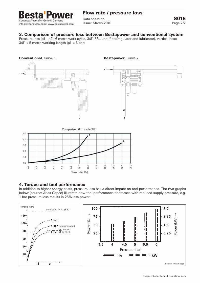
Conductix-Wampfler GmbH | [email protected] | www.bestapower.com
5.0
4.0
3.0
2.0
1.0
0.0
0.0
1.7
3.3
5.0
6.7
8.3
10.0
11.7
13.3
15.0
16.7
18.3
20.0
torque (Nm)yield point M 12 (8.8)
recommended torque for M 12 (8.8)
Pressure (bar)
Pow
er (
%) →
Pow
er (
kW) →
3. Comparison of pressure loss between Bestapower and conventional system Pressure loss (p1 - p2), 6 metre work cycle, 3/8" FRL unit (filter/regulator and lubricator), vertical hose 3/8" x 5 metre working length (p1 = 6 bar)
4. Torque and tool performanceIn addition to higher energy costs, pressure loss has a direct impact on tool performance. The two graphs below (source: Atlas Copco) illustrate how tool performance decreases with reduced supply pressure, e.g. 1 bar pressure loss results in 25% less power.
Flow rate (l/s)
Comparison 6 m cycle 3/8"
Conventional, Curve 1 Bestapower, Curve 2
Source: Atlas Copco
Subject to technical modifications
Flow rate / pressure lossData sheet no. S01EIssue: March 2010 Page 2/2

Conductix-Wampfler GmbH | [email protected] | www.bestapower.com
1.
2.
Type 12698 Assembly deviceThe assembly device ensures the correct coupling installation depth during instal-lation in the rail section (limit stop).
Type 12697 Pull-out deviceThis devices is required for pulling out the coupling 12500 / 12501 from the rail section.(See Product-Information LPP18)
Type 12699 Displacement deviceThis device can be used for moving couplings into position after installa-tion in order to enable removal of a rail section.(See Product-Information LPP17)
Type 6350 Drill jigThe drill jig is used for precise drilling of the holes required for mounting the coupling on trimmed A62/A180 rail sections.(See Product-Information LPP15)
The drill is not included.
Type 12695 Deburring SetThis tool can be used for deburring the cutting edges of the trimmed rail section and the drill holes.
Notice: Correct deburring prevents damage to the O-rings and leakage. (See Product-Information LPP15)
Tools / Assembly aidsData sheet no. W01EIssue: March 2010 Page 1/1
Subject to technical modifications
Installation
1. For deburring drill holes2. For deburring the cutting edge
Removal
The blades are stashed into the knob of the deburring-tool.