· unclassified unclassified evaluation of a model driven computer science master thesis software...
TRANSCRIPT

UNCLASSIFIED
UNCLASSIFIED
Computer Science Master Thesis Software Engineering Chair Graduation committee: Prof. Dr. ir. M. Aksit, Software Engineering Group, University of Twente Dr. ir. K.G. van den Berg, Software Engineering Group, University of Twente Ir. I. Kurtev, Software Engineering Group, University of Twente Ir. M. Ponsen, Thales Naval Nederland Dr. ir. R.F. Lutje Spelberg, Thales Naval Nederland
Evaluation of a Model Driven Architecture model transformation language:
The Transformation Rule Language Version 0.94
W.J. Bonestroo
July 2004


UNCLASSIFIED
Supervisor Thales Stagebureau Thales
UNCLASSIFIED


PREFACE
Preface
This thesis is the description of the project I carried out to acquire my Computer Science master's degree. In 1998 I started my studies at the University of Twente. To me, the beauty of computer science lay in the solution of real-world problems using an abstract mathematical approach. At the start of my studies, I had no experience in software development at all. Now, six years later, the last phase of my studies has arrived and I have the feeling I know quite a lot about it. The studies provided foundational knowledge. Work and side projects provided specialized knowledge and hands-on experience. This last year I’ve done my internship at Versatel and I’ve been working on this graduation project at Thales. This took up a lot of time, at least more than I was used to. In addition, I have the extremely time consuming hobby of drumming and these things together resulted in a rather busy year. As a result, I can now sincerely say that I am relieved and satisfied that this part of my studies is finished. At this place I want to thank people who provided help and assistance during this project. I want to thank Klaas van den Berg and Ivan Kurtev, who were my supervisors at the university. Furthermore, I would like to thank Thales’ supervisors Monique Ponsen and Ronald Lutje Spelberg. I want to thank the following other people from Thales: Rene de Jong, Jan Willem Lokin and Erik Hendriks. I also want to thank Ron Foederer who was my supervisor in the first phase of the project. Last but not least, I want to thank my roommates Emiel Schuurman and Jeroen van Gorkum. The evaluation of the language was conducted using a prototype compiler developed by Mariano Belaunde from France Telecom. I want to thank him for the help I received to get the software up and running. Finally, I want to thank my parents and family for their support during the past few years. Without their help I wouldn't be in the position I am right now. Hengelo, The Netherlands, 2004 Wilco Bonestroo PS. To some (ex) residents of Calslaan 40, who claimed that life only gets worse after finishing your studies, I want to say: I hope you were wrong, but I will soon find it out myself!
UNCLASSIFIED i

SAMENVATTING (IN DUTCH)
Samenvatting (in Dutch)
The Model Driven Architecture (MDA), oftewel de Model Gedreven Architectuur, is een relatief nieuwe benadering van software ontwikkeling. Het is opgezet door de Object Management Group (OMG) in 2001. In MDA bevat de specificatie van een systeem niet de details om het systeem te implementeren op een bepaald platform. De beschrijving van een systeem op verschillende abstractieniveaus is een belangrijk onderdeel van MDA. Een Platform Independent Model (PIM), oftewel een platformonafhankelijk model, beschrijft een systeem onafhankelijk van het onderliggende platform. Een Platform Specific Model (PSM), oftewel platformafhankelijk model, beschrijft hetzelfde systeem, maar het bevat constructies die specifiek zijn voor het platform. Een van de voordelen van MDA is de mogelijkheid om, middels automatische transformaties, platformspecifieke elementen aan modellen toe te voegen, dus om PIMs om te zetten in PSMs. Ontwikkelaars kunnen zich richten op de functionaliteit en de platform specifieke details worden automatisch ingevoegd. Om transformaties te standaardiseren heeft de OMG een Request for Proposals (RFP), een verzoek om voorstellen, gedaan voor Queries, Views en Transformaties. De modeltransformatietaal Transformation Rule Language (TRL) is het QVT voorstel dat door onder andere Thales is ingediend. Dit afstudeerverslag bevat een evaluatie van TRL. Er is een casestudy uitgevoerd, waarin een PIM-naar-PSM transformatie is gespecificeerd met de taal. Een PIM is omgezet naar een Data Distributie Service (DDS) gerichte PSM. In MDA termen is DDS het platform. De transformatie voegde DDS specifieke constructies toe aan het DDS onafhankelijke model. De QVT RFP eiste om een declaratieve taal voor te stellen. TRL heeft declaratieve regels, die het resultaat van een transformatie beschrijven, maar ook imperatieve regels, die beschrijven hoe een transformatie moet worden uitgevoerd. Of TRL voldoet aan de eisen van QVT hangt dus af van de interpretatie van deze eisen. De casestudy heeft aangetoont dat het mogelijk is om een DDS gerichte PIM-naar-PSM transformatie uit te drukken in TRL. De taal heeft gespecialiseerde constructies om elementen uit een verzameling te filteren en om regels voor ieder element van een verzameling aan te roepen. Hierdoor kan je compacte staments maken. TRL heeft echter ook aan aantal eigenschappen die niet wenselijk zijn in een modeltransformatietaal. Traceability, de mogelijkheid om relaties tussen bron en doel te bewaren en te volgen, is alleen tijdens transformaties beschikbaar en niet daarna. Traceability is noodzakelijk voor “conservative generation”. Conservative generation betekent dat elementen de bestaande elementen niet overschrijven. TRL heeft geen specifieke constructies om het probleem van de regelvolgorde op te lossen. De ontwikkelaar moet zich bewust zijn van de problemen die hierbij ontstaan.
UNCLASSIFIED ii

SUMMARY
Summary
The Model Driven Architecture (MDA) is a relatively young approach to software development. It was initiated by the Object Management Group (OMG) in 2001. In MDA the specification of the system does not contain the details necessary to implement the system on a particular platform. The description of a system at different levels of abstraction is an important characteristic of MDA. A Platform Independent Model (PIM) describes the system in a way that is independent of the underlying platform. A Platform Specific Model (PSM) describes the same system, but it contains platform specific constructs. The transformation from a PIM to a PSM introduces platform specific details. The possibility of automatic model transformations is an appealing characteristic of MDA. Developers can focus on the platform independent system functionality, while the platform specific details are introduced by a transformation. To standardize such transformations in MDA, the OMG issued a request for proposals (RFP) for Queries, Views and Transformations (QVT). The model transformation language Transformation Rule Language (TRL) is the QVT proposal that was submitted by Thales. This thesis contains an evaluation of TRL. A case study was performed using the language for the specification of a PIM-to-PSM transformation. This transformation transforms a PIM into a Data Distribution Service (DDS) oriented PSM. In MDA terminology, DDS is the target platform. The transformation adds DDS specific constructs to the DDS independent model. The QVT RFP requested a declarative language. TRL has declarative rules that describe the result of a transformation, but also imperative rules that describe how to execute a transformation. Thus, the validity of the TRL QVT proposal depends on the interpretation of the mandatory QVT requirements. The case study showed that it is possible to implement a DDS-oriented PIM-to-PSM transformation in TRL. The language has specialized constructs that can be used to filter elements from a set and call rules for each element in a set. This results in compact statements. However, TRL does also have a number of characteristics that are not desirable in a model transformation language. Traceability is only available during transformation execution and not afterwards. Traceability is necessary for conservative generation, in which changes are not overwritten. TRL does not have specific constructs to solve the rule execution order problem. Thus, the developer is responsible to encode the transformation rules execution explicitly.
UNCLASSIFIED iii
ABBREVIATIONS
Abbreviations
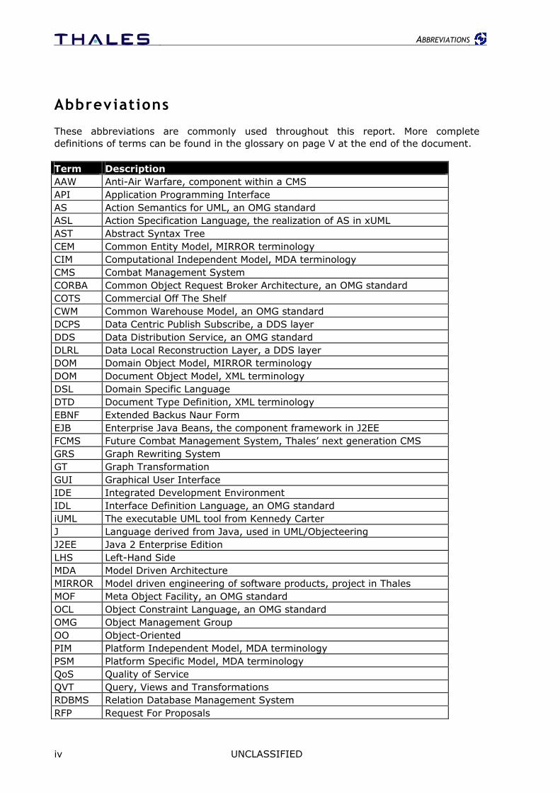
These abbreviations are commonly used throughout this report. More complete definitions of terms can be found in the glossary on page V at the end of the document.
Term Description AAW Anti-Air Warfare, component within a CMS API Application Programming Interface AS Action Semantics for UML, an OMG standard ASL Action Specification Language, the realization of AS in xUML AST Abstract Syntax Tree CEM Common Entity Model, MIRROR terminology CIM Computational Independent Model, MDA terminology CMS Combat Management System CORBA Common Object Request Broker Architecture, an OMG standard COTS Commercial Off The Shelf CWM Common Warehouse Model, an OMG standard DCPS Data Centric Publish Subscribe, a DDS layer DDS Data Distribution Service, an OMG standard DLRL Data Local Reconstruction Layer, a DDS layer DOM Domain Object Model, MIRROR terminology DOM Document Object Model, XML terminology DSL Domain Specific Language DTD Document Type Definition, XML terminology EBNF Extended Backus Naur Form EJB Enterprise Java Beans, the component framework in J2EE FCMS Future Combat Management System, Thales’ next generation CMS GRS Graph Rewriting System GT Graph Transformation GUI Graphical User Interface IDE Integrated Development Environment IDL Interface Definition Language, an OMG standard iUML The executable UML tool from Kennedy Carter J Language derived from Java, used in UML/Objecteering J2EE Java 2 Enterprise Edition LHS Left-Hand Side MDA Model Driven Architecture MIRROR Model driven engineering of software products, project in Thales MOF Meta Object Facility, an OMG standard OCL Object Constraint Language, an OMG standard OMG Object Management Group OO Object-Oriented PIM Platform Independent Model, MDA terminology PSM Platform Specific Model, MDA terminology QoS Quality of Service QVT Query, Views and Transformations RDBMS Relation Database Management System RFP Request For Proposals
UNCLASSIFIED iv

ABBREVIATIONS
RHS Right-Hand Side SPLICE Subscription Paradigm for the Logical Interconnection of Concurrent
Engines, a software architecture from Thales SQL Structured Query Language SRS Software Requirements Specification TE Threat Evaluation, component within AAW TM DCPS Topic Model, MIRROR terminology TNNL Thales Naval Nederland TRESE Twente Research and Education of Software Engineering TRL Transformation Rule Language TRT Thales Research and Technology UML Unified Modeling Language, an OMG standard XMI XML Metadata Interchange, an OMG standard XML eXtensible Modeling Language, a W3C standard XSL XML Style sheet Language, a W3C standard XSLT XSL Transformation, a W3C standard xUML Executable UML as realized by Kennedy Carter in the iUML tool
Table 1 Abbreviation List
UNCLASSIFIED v

ABBREVIATIONS
UNCLASSIFIED vi
OVERVIEW
Overv iew
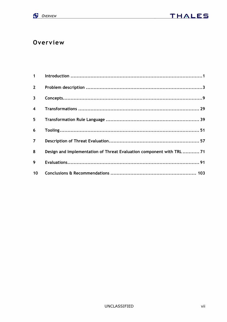
1 Introduction ......................................................................................1 2 Problem description ............................................................................3 3 Concepts...........................................................................................9 4 Transformations ............................................................................... 29 5 Transformation Rule Language ............................................................. 39 6 Tooling........................................................................................... 51 7 Description of Threat Evaluation........................................................... 57 8 Design and Implementation of Threat Evaluation component with TRL ........... 71 9 Evaluations...................................................................................... 91 10 Conclusions & Recommendations ........................................................ 103
UNCLASSIFIED vii

TABLE OF CONTENTS
Table of Contents
Preface .................................................................................................... i Samenvatting (in Dutch) .............................................................................. ii Summary .................................................................................................iii Abbreviations............................................................................................iv Overview ................................................................................................ vii Table of Contents .................................................................................... viii List of Figures ..........................................................................................xii List of Tables .......................................................................................... xiii List of Equations ...................................................................................... xiv List of Code fragments .............................................................................. xiv 1 Introduction ..................................................................................... 1
1.1 Context ...................................................................................................1 1.2 Document Conventions ..............................................................................1 1.3 Thesis Outline ..........................................................................................2
2 Problem description ........................................................................... 3 2.1 Background..............................................................................................3
2.1.1 The Model Driven Architecture (MDA).................................................................3 2.1.2 Thales ...........................................................................................................4 2.1.3 TRESE ...........................................................................................................5
2.2 Problem statement....................................................................................5 2.3 Main Research Questions ...........................................................................6 2.4 Research subquestions ..............................................................................6 2.5 Deliverables .............................................................................................6 2.6 Scope......................................................................................................6 2.7 Summary.................................................................................................7
3 Concepts.......................................................................................... 9 3.1 Model Driven Architecture ..........................................................................9
3.1.1 Models ..........................................................................................................9 3.1.2 Metamodels ................................................................................................. 10 3.1.3 Platforms..................................................................................................... 10 3.1.4 Viewpoints ................................................................................................... 11 3.1.5 Unified Modeling Language (UML).................................................................... 11 3.1.6 Meta Object Facility (MOF) ............................................................................. 14 3.1.7 Object Constraint Language (OCL)................................................................... 15 3.1.8 Model Transformations................................................................................... 16 3.1.9 Software engineering process ......................................................................... 17
3.2 Query / Views / Transformations ............................................................... 17 3.2.1 QVT Requirements ........................................................................................ 18 3.2.2 Abstract versus concrete syntaxes................................................................... 23 3.2.3 QVT proposals .............................................................................................. 25
3.3 Summary............................................................................................... 27 4 Transformations ...............................................................................29
4.1 Transformations in MDA........................................................................... 29 4.2 Transformation Techniques....................................................................... 30
4.2.1 XMI XSLT approach ....................................................................................... 30 4.2.2 Tool dependent transformations ...................................................................... 32
UNCLASSIFIED viii

TABLE OF CONTENTS
4.2.3 Graph based transformations ..........................................................................32 4.2.4 DSL for transformations .................................................................................33 4.2.5 General-purpose language with API .................................................................34
4.3 Software Quality Measurement .................................................................34 4.4 Desired properties of transformations ........................................................35
4.4.1 Tuneability ...................................................................................................35 4.4.2 Traceability ..................................................................................................36 4.4.3 Incremental consistency.................................................................................36 4.4.4 Bi-directionality.............................................................................................37 4.4.5 Expressive power ..........................................................................................37 4.4.6 Readability ...................................................................................................37 4.4.7 Portability ....................................................................................................37 4.4.8 Durability .....................................................................................................37 4.4.9 Composition capability ...................................................................................37 4.4.10 Open standards based ................................................................................38
4.5 Pending problems ...................................................................................38 4.6 Summary...............................................................................................38
5 Transformation Rule Language ............................................................. 39 5.1 TRL Introduction .....................................................................................39 5.2 Language structure .................................................................................39
5.2.1 TRL’s Abstract Syntax ....................................................................................40 5.2.2 TRL’s Concrete Syntax ...................................................................................40 5.2.3 Implementation of TRL...................................................................................41
5.3 Classification of TRL ................................................................................41 5.3.1 Model transformations ...................................................................................42 5.3.2 Transformation Rules.....................................................................................42 5.3.3 Rule Application Scoping ................................................................................44 5.3.4 Relationship between Source and Target...........................................................45 5.3.5 Rule Application Strategy ...............................................................................45 5.3.6 Rule Scheduling ............................................................................................46 5.3.7 Rule Organization..........................................................................................47 5.3.8 Traceability Links ..........................................................................................48 5.3.9 Directionality ................................................................................................49 5.3.10 Queries.....................................................................................................49
5.4 Summary...............................................................................................50 6 Tooling........................................................................................... 51
6.1 TRL compiler ..........................................................................................51 6.1.1 Univers@lis ..................................................................................................51 6.1.2 Metamodels..................................................................................................53 6.1.3 Bases ..........................................................................................................53 6.1.4 The compiler ................................................................................................53 6.1.5 Cygwin ........................................................................................................54
6.2 Objecteering/UML ...................................................................................54 6.2.1 UML Profile Builder ........................................................................................54 6.2.2 UML modeler ................................................................................................55
6.3 EditPlus .................................................................................................56 6.4 Summary...............................................................................................56
7 Description of Threat Evaluation........................................................... 57 7.1 Introduction ...........................................................................................57
7.1.1 Project Background .......................................................................................57 7.1.2 SPLICE & DDS ..............................................................................................58 7.1.3 DDS Architecture ..........................................................................................58 7.1.4 The big picture..............................................................................................59
UNCLASSIFIED ix
TABLE OF CONTENTS
7.1.5 Another view of the big picture ....................................................................... 63 7.2 MDA and MIRROR ................................................................................... 64
7.2.1 Transformations in MDA................................................................................. 64 7.2.2 Alternative view of Transformations in MIRROR ................................................. 64
7.3 Mappings between models........................................................................ 66 7.3.1 Mappings ..................................................................................................... 66 7.3.2 UML constructs ............................................................................................. 67 7.3.3 Conclusion ................................................................................................... 69
7.4 Summary............................................................................................... 69 8 Design and Implementation of Threat Evaluation component with TRL ...........71
8.1 Requirements......................................................................................... 71 8.1.1 Functional requirements................................................................................. 71 8.1.2 Non-functional requirements........................................................................... 75
8.2 Test cases.............................................................................................. 75 8.2.1 Structure creation ......................................................................................... 75 8.2.2 PIM specific classes ....................................................................................... 76 8.2.3 Association................................................................................................... 77 8.2.4 Generalization .............................................................................................. 77
8.3 Design .................................................................................................. 78 8.3.1 Source model structure.................................................................................. 79 8.3.2 Depth-first versus breadth-first ....................................................................... 79 8.3.3 Phases ........................................................................................................ 81
8.4 TRL Implementation ................................................................................ 81 8.4.1 Class Creation .............................................................................................. 81 8.4.2 Structure Creation......................................................................................... 81 8.4.3 Stereotypes ................................................................................................. 84 8.4.4 Implementing an Interface ............................................................................. 84 8.4.5 Inheritance .................................................................................................. 85
8.5 Implementation ...................................................................................... 85 8.5.1 Activity Diagram ........................................................................................... 85 8.5.2 Test cases.................................................................................................... 86 8.5.3 Design error................................................................................................. 87 8.5.4 Performance................................................................................................. 87
8.6 Summary............................................................................................... 89 9 Evaluations......................................................................................91
9.1 TRL’s conformance to the QVT RFP ............................................................ 91 9.1.1 Mandatory Requirements Conformance ............................................................ 91 9.1.2 Optional Requirements Conformance ............................................................... 93 9.1.3 Discussion Issues Conformance....................................................................... 94 9.1.4 Evaluation Criterion Conformance.................................................................... 95
9.2 Evaluation of TRL according to the Desired properties .................................. 95 9.2.1 Tuneability................................................................................................... 95 9.2.2 Traceability .................................................................................................. 96 9.2.3 Incremental consistency................................................................................. 96 9.2.4 Bi-directionality ............................................................................................ 96 9.2.5 Expressive power .......................................................................................... 96 9.2.6 Readability................................................................................................... 96 9.2.7 Portability .................................................................................................... 96 9.2.8 Durability..................................................................................................... 97 9.2.9 Composition capability ................................................................................... 97 9.2.10 Open standard........................................................................................... 97
9.3 Empiric Evaluation of TRL......................................................................... 97 9.4 TRL Compiler Quality ............................................................................... 98
UNCLASSIFIED x

TABLE OF CONTENTS
9.4.1 External characteristics ..................................................................................98 9.4.2 TRL Compiler Quality in Use.......................................................................... 100
9.5 Summary............................................................................................. 101 10 Conclusions & Recommendations ........................................................ 103
10.1 Answers to the research questions........................................................ 103 10.2 Answers to the main research questions ................................................ 106 10.3 Conclusions ....................................................................................... 108 10.4 Recommendations .............................................................................. 109
10.4.1 Thales MIRROR ........................................................................................ 109 10.4.2 TRL developers ........................................................................................ 110
References................................................................................................ I Glossary .................................................................................................. V Appendices .............................................................................................. IX Appendix A Case Study description ............................................................XI
A.1 Description of transformations ................................................................ XIII A.1.1 PIM Profile.................................................................................................. XIII A.1.2 PIM to PSM transformations .......................................................................... XIV
Appendix B EditPlus syntax file............................................................... XIX Appendix C Transformations expressed in J ............................................... XXI
C.1 The J code ........................................................................................... XXI C.2 The results.......................................................................................... XXII
Appendix D TRL specification ................................................................ XXV Appendix E TRL Case Study Transformation Code ........................................XXVII Appendix F Univers@lis Scripts ............................................................. XXXI Appendix G PIM-to-PSM transformation scenarios ..................................... XXXIII
G.1 Scenario 1: Express transformation directly in tool................................. XXXIII G.2 Scenario 2: Use TRL directly ................................................................XXXIV G.3 Scenario 3: Use XSLT .........................................................................XXXIV G.4 Scenario 4: Own Implementation that generates J ...................................XXXV G.5 Scenario 5: Use TRL to transform TRL to J ..............................................XXXV G.6 The used approach.............................................................................XXXVI
Appendix H Java and TRL comparison................................................... XXXVII Index ................................................................................................XXXIX
UNCLASSIFIED xi

LIST OF FIGURES
List of Figures
Figure 1 Simplified DDS architecture.......................................................................5 Figure 2 Scope: PIM-to-PSM transformations ...........................................................7 Figure 3 Metamodel / model example ................................................................... 10 Figure 4 Dependencies in the Core package (based on [40]) .................................... 12 Figure 5 MOF based extension ............................................................................. 13 Figure 6 Profile based extension........................................................................... 13 Figure 7 MOF 2.0 Elements (based on [36])........................................................... 14 Figure 8 four-layer MOF architecture..................................................................... 15 Figure 9 OCL example ........................................................................................ 15 Figure 10 Model Transformation (based on [33]) .................................................... 16 Figure 11 MOF Abstract Syntax example ............................................................... 23 Figure 12 AST example....................................................................................... 24 Figure 13 PIM-to-PSM, UML-to-UML Transformations............................................... 29 Figure 14 A graph transformation......................................................................... 33 Figure 15 Transformation Rule Language overview ................................................. 41 Figure 16 Top-level Feature Diagram (based on [9]) ............................................... 42 Figure 17 Transformation Rules Feature Diagram (based on [9]) .............................. 42 Figure 18 Transformation Rules for TRL................................................................. 43 Figure 19 LHS/RHS mixture in TRL ....................................................................... 43 Figure 20 Rule Application Scoping feature diagram (based on [9]) ........................... 44 Figure 21 Relationship between Source and Target feature diagram (based on [9]) ..... 45 Figure 22 Relationship between Source and Target for TRL ...................................... 45 Figure 23 Rule Application Strategy Feature Diagram (based on [9]) ......................... 45 Figure 24 Rule Application Strategy for TRL ........................................................... 46 Figure 25 Rule Scheduling Feature Diagram (based on [9])...................................... 46 Figure 26 Rule Scheduling for TRL ........................................................................ 46 Figure 27 Rule Organization Feature Diagram (based on [9]) ................................... 47 Figure 28 Rule Organization for TRL...................................................................... 47 Figure 29 Unit inheritance ................................................................................... 47 Figure 30 Rule inheritance................................................................................... 48 Figure 31 Tracing Feature Diagram (based on [9]).................................................. 48 Figure 32 Tracing Feature for TRL......................................................................... 49 Figure 33 Directionality Feature Diagram (based on [9]).......................................... 49 Figure 34 Directionality for TRL............................................................................ 49 Figure 35 Tooling used in the Case Study .............................................................. 51 Figure 36 Univers@lis model repository................................................................. 51 Figure 37 Univers@lis Web Interface (screenshot) .................................................. 53 Figure 38 TRL compilation ................................................................................... 54 Figure 39 Relationship between profiles................................................................. 55 Figure 40 The Objecteering approach overview ...................................................... 56 Figure 41 DDS Architecture ................................................................................. 59 Figure 42 DCPS–DLRL Schematic Overview (based on [34]).................................... 60 Figure 43 Component Realization (based on [34]) .................................................. 60 Figure 44 System Design (based on [34]) ............................................................. 61 Figure 45 Component Integration (based on [34]) .................................................. 62 Figure 46 DCPS-DLRL Graphic Overview (taken from [34]) ...................................... 63 Figure 47 MDA pattern (taken from [33]) .............................................................. 64 Figure 48 Top-level View of Transformation in MIRROR............................................ 65 Figure 49 Alternative Transformation Overview ...................................................... 65
UNCLASSIFIED xii
LIST OF TABLES
Figure 50 Mappings in MIRROR ............................................................................66 Figure 51 Elements in the Relationships Package (taken from [43])...........................67 Figure 52 Dependencies package (taken from [44]) ................................................68 Figure 53 PIM Class (taken from [34]) ..................................................................72 Figure 54 PSM Class Structure (taken from [34])....................................................72 Figure 55 PIM inheritance (taken from [34]) ..........................................................73 Figure 56 PSM Inheritance (taken from [34]) .........................................................73 Figure 57 PIM relation (taken from [34]) ...............................................................74 Figure 58 PSM Relation (taken from [34])..............................................................74 Figure 59 Tree traversal example .........................................................................80 Figure 60 Binary Composition Association ..............................................................82 Figure 61 Association Element Structure................................................................82 Figure 62 Activity Diagram ..................................................................................86 Figure 63 Package Structure................................................................................87 Figure 64 Execution Duration Time Graph..............................................................88 Figure 65 Threat Evaluation PIM........................................................................... XI Figure 66 Detailed PIM classes: OwnShip, Threat and ThreadEvaluator ...................... XI Figure 67 Threat Evaluation sequence diagram (incomplete) ................................... XII Figure 68 Threat Evaluation PSM (Application Component part) ............................... XII Figure 69 Threat Evaluation PSM (DLRL part) ....................................................... XIII Figure 70 PIM Profile ........................................................................................ XIII Figure 71 Basic PIM PSM transformation.............................................................. XIV Figure 72 PIM PSM Generalization transformation ...................................................XV Figure 73 PIM PSM Association with multiplicity one ................................................XV Figure 74 PIM PSM Association with multiplicity many ........................................... XVI Figure 75 Relevant UML classes........................................................................ XVIII Figure 76 Transformation results ...................................................................... XXIII Figure 77 Scenario 1 .................................................................................... XXXIII Figure 78 Scenario 2 .....................................................................................XXXIV Figure 79 Scenario 2 (detailed) .......................................................................XXXIV Figure 80 Scenario 3 ......................................................................................XXXV Figure 81 Scenario 4 ......................................................................................XXXV Figure 82 Scenario 5 .....................................................................................XXXVI
List of Tables
Table 1 Abbreviation List.......................................................................................v Table 2 Product Quality External Characteristics .....................................................35 Table 3 Quality in Use Characteristics ...................................................................35 Table 4 Requirements Summary...........................................................................74 Table 5 Test Case General Structure .....................................................................76 Table 6 PIM specific classes Test Cases .................................................................77 Table 7 Association Test Cases.............................................................................77 Table 8 Inheritance Test Cases ............................................................................78 Table 9 Multiplicity Ranges ..................................................................................79 Table 10 Test Case Results..................................................................................87 Table 11 Execution Duration Times.......................................................................88 Table 12 Mandatory Requirements Conformance ....................................................92 Table 13 Optional Requirements Conformance........................................................94 Table 14 Functional Implementation Coverage for TRL.............................................99 Table 15 EBNF constructs..................................................................................XXV
UNCLASSIFIED xiii
LIST OF EQUATIONS
List of Equations
Equation 1 A language........................................................................................ 24 Equation 2 Semantic mapping ............................................................................. 25 Equation 3 Concrete syntactic mapping................................................................. 25 Equation 4 Approximate Execution Duration........................................................... 88
List of Code fragments
Code fragment 1 EBNF example ........................................................................... 23 Code fragment 2 Program example ...................................................................... 24 Code fragment 3 XML sample .............................................................................. 30 Code fragment 4 XSLT sample ............................................................................. 31 Code fragment 5 Association Creation Signatures ................................................... 82 Code fragment 6 Local Variable Usage .................................................................. 83 Code fragment 7 MultiplicityRanges ...................................................................... 83 Code fragment 8 Stereotypes .............................................................................. 84 Code fragment 9 Implementation of an Interface.................................................... 85 Code fragment 10 Generalization ......................................................................... 85
UNCLASSIFIED xiv

INTRODUCTION
1 Introduction
The Model Driven Architecture (MDA) [33] uses models for the development of software. In current software development processes, models are already used for design and documentation purposes. In MDA, models can be used to generate software. To achieve this generation, platform independent models are (semi) automatically transformed to platform specific models. These platform specific models can be transformed to executable code. One of the approaches for model transformation is the usage of a specialized model transformation language. The Transformation Rule Language (TRL) is such a language. In this project TRL is evaluated to see if it’s appropriate to express model transformations. To evaluate the language, a case study using TRL was carried out. This document describes the evaluation of TRL and the conclusions of this evaluation.
1 .1 Context This document is a description of a master’s project. The project was carried out for the studies of Computer Science in the Software Engineering group [54]. This (external) assignment was conducted within Thales Naval Nederland B.V. Thales creates defense solutions for naval and ground based environments and has a vast expertise in the fields of radar, infrared, weapon control, display technology and communications equipment. [47][53] MIRROR is a project of the Thales Group. MIRROR TNNL is the Dutch part of the project that is carried out in Thales Naval Nederland (TNNL). The project’s main objective is to perform an early validation of the concepts of MDA. To achieve this, functionality of the Anti Air Warfare (AAW) component for the Future Combat Management System is developed using MDA. The purposes of the validation are:
• Enhancement of current development practice by introducing MDA concepts; • Building of knowledge on near-future development technologies; • Development of functionality of Anti Air Warfare for the Future Combat
Management System; This report provides MIRROR knowledge on the subject of model transformations and more specific on model transformation languages.
1 .2 Document Convent ions References to other documents are indicated as numbers enclosed in square brackets, for example [45]. The references are listed on page I at the end of the report. When “Thales” is mentioned, Thales Naval Nederland (TNNL) is meant, unless stated otherwise. When “Thales’ proposal” is mentioned, the QVT proposal from Alcatel, Softeam, Thales and TNI-Valiosys [1] is meant. “The TRL compiler” refers to the prototype of a TRL compiler that was build by France Telecom [15]. A monospaced font is used to indicate pieces of code or to refer to variable names, types or classes. When such names have capitals, these capitals are also used in the text (e.g. AssociationEnd).
UNCLASSIFIED 1

INTRODUCTION
Words using the prefixes meta, sub or super are written as one word (e.g. metaclass, subclass). Also words with the postfix “ability” are written as one word (e.g. tuneability, traceability). Within the model driven architecture, several names are used to indicate the process of software development based on the Model Driven Architecture. Model Driven Development (MDD) and Model Driven Engineering (MDE) are used to indicate software development that uses the MDA architecture and MDA tools. Although the separation between the architecture and the process is a good thing, in this document Model Driven Architecture is used to indicate both the architecture and the software development process.
1 .3 Thes i s Out l i ne In chapter 2 the problem description of this assignment is presented. First, the problem statement is formulated precisely. The purpose of this assignment is to solve the problems described in the problem statement. To guide this solution, a number of research questions is stated and answered later on in the document. Chapter 3 presents related information and techniques that are required in this assignment. The chapter contains no new concepts, but it describes concepts from MDA and QVT that the reader must be familiar with, in order to understand the subject. In chapter 4 the generic principle of transformations is explained. The approach that is evaluated in this document is only one of the approaches to perform a model transformation. Chapter 5 describes the language that is under evaluation: TRL. First, the structure of the specification documents is explained. Then the features of the language are explicitly shown using features diagrams for model transformation languages. Chapter 6 describes the tools that were used during this assignment. The assignment involved modeling, specifying transformations and compiling and running transformations. All the involved software is described. Also some configuration files and scripts that were used are presented, so that the activities done for this assignment can later be reproduced. In chapter 7, the context for the case study is presented. The case is a part of a larger project conducted within MIRROR. The chapter explains the processes and artifacts in the project and the relations among them. In chapter 8, the implementation of the case study is discussed. The analysis, design, implementation and the testing of the software are described. Chapter 9 presents the results of several evaluations. The compiler software and the language itself are evaluated based on several approaches. Finally, chapter 10 contains the conclusions and recommendations that are the result of this assignment. An answer to the problem statement is given, the research questions are answered and recommendations and possible future work are discussed.
UNCLASSIFIED 2

PROBLEM DESCRIPTION
2 Problem description
This chapter describes the problem that is addressed in this report. Section 2.2 contains the problem statement for this assignment. In sections 2.3 and 2.4, a number of research questions are formulated. The research questions are divided into main research questions and a number of subquestions. The main questions describe the focus of this thesis. The subquestions are used to guide the research and to answer the main questions.
2 .1 Background This section describes the need for both Thales and the Software Engineering group to gain knowledge about model transformations in MDA.
2.1.1 The Model Dr iven Archi tecture (MDA) Development of the Model Driven Architecture (MDA) resulted in the demand for model transformation languages. This section briefly introduces the concepts of software engineering based on MDA.
2.1.1.1 Evolution in Software Engineering The development of large software systems is a complex process. In the past few decades, several techniques have been developed to cope with this complexity. Assembly languages, structured programming, higher level programming languages, object orientation (modeling, design and implementation), software engineering methods, design patterns, frameworks, architectures and advanced integrated development environments (IDEs) are all techniques developed to get a better grip on the complex software development process. Current software development processes, such as the Unified Process [27], use models for understanding and design. These design models are used as blueprints to guide the implementation of the software, but there is no hard link between the designed models and the implemented code. Models are manually converted to code and changes to the system can be made without updating the designs. As projects grow, it’s more and more difficult to keep the code and design models consistent.
2.1.1.2 MDA and Transformations MDA is a relatively new software development approach that separates the specification of the system from the platform dependent implementation details. Different types of models with different levels of abstraction are used to achieve this separation of concerns. A higher level of abstraction provides more control during software development and, more important, during deployment and maintenance. Because most of the costs of software are in the maintenance, reduction of these costs has a great impact on the total costs of computer systems [29][16]. One of MDA’s principles is the usage of models as development artifacts instead of pure design artifacts. This means that models are directly used to create software. Some kind of transformation is needed to create models or executable software from models. To enable such transformations, models must be expressed in a machine-readable, well-defined manner.
UNCLASSIFIED 3

PROBLEM DESCRIPTION
The principle of transformations is definitely not new in the computer science area. The terms transformation, translation and compilation are conceptually very similar. An output model is generated based on an input model. One must notice that programming code or generated documentation can also be seen as a model. So, ordinary compilation is also a kind of model transformation. Although the standardization of transformations is still in progress, several techniques for transformations exist and some are already implemented in software development tools. Different vendors now use their own ways to describe and execute transformations. One of the keywords in MDA terminology is platform independency. Tool specific transformations definitely do not contribute to independency. Hence a tool independent approach is desirable for transformations. The ultimate goal of MDA would be the complete generation of executable software from high-level models. Although this seems like a far away future vision, several tools can completely build systems from models already. MDA is explained in more detail in section 3.1.
2.1.2 Thales Like in other industries, the systems that Thales develops become more and more complex. The radars and other sensors used nowadays, continually generate a huge amount of detailed information that must be processed by the Combat Management System (CMS). Furthermore, a CMS must be able to operate under extreme circumstances such as combat situations. Therefore the systems need qualities such as real-time processing, fault tolerance, automatic reallocation of software components, etc. These requirements result in complex systems to be developed. One possible approach to cope with the complexity of these systems is the use of MDA. Thales investigates techniques that could be used to build its future systems. MIRROR is a pilot project conducted within Thales. Thales Research and Technology (TRT) is a French research department of Thales leading MIRROR. MIRROR TRT has been focusing on the use of MDA tools for the implementation of Corba Component Model (CCM) based systems. MIRROR TRT uses the Objecteering/UML toolset developed by Softeam [50]. Thales Naval Nederland (TNNL) is also involved in the MIRROR project. MIRROR TNNL develops an Anti Air Warfare (AAW) component, Thread Evaluation (TE), with IBM/Rational’s XDE tools for modeling [21]. AAW is a part of a Combat Management System (CMS) and TE is a part of AAW. The current CMS uses a dedicated proprietary platform called SPLICE. Splice is a data distribution service (DDS) based on the publish-subscribe mechanism. Currently, Thales is, among others, establishing an OMG standard to standardize this publish-subscribe mechanism. This standard is called Data Distribution Service (DDS). DDS consists of two main layers: The Data Centric Publish Subscribe (DCPS) layer and the Data Local Reconstruction Layer (DLRL). Therefore, DDS has a layered architecture. To sum up, An OO CMS based on DDS can be build using the DDS architecture. DDS consists of 2 layers, the DCPS and the DLRL. One of the components of the CMS is AAW. TE is component within AAW. The relation between TE, AAW, DDS, DLRL and DCPS is illustrated in Figure 1
UNCLASSIFIED 4

PROBLEM DESCRIPTION
DCPSDCPSDLRLDLRL
Anti Air WarfareAnti Air Warfare
Threat Evaluation
Threat Evaluation
An ObjectOriented, DDS
basedCombat
ManagementSystem
Figure 1 Simplified DDS architecture
MIRROR builds a TE component based on DDS. The idea is to develop a PIM describing the component and a PSM describing the implementation of that component. The transformation from PIM to PSM is a task, first done manually, that would preferably be executed automatically.
2.1.3 TRESE Twente Research and Education of Software Engineering (TRESE) is an umbrella project in which the Software Engineering chair is involved. The main research topic of the TRESE software engineering group is Quality-oriented Software Engineering (QoSE). As the name suggests, QoSE is focused on software engineering quality factors. Examples of these factors are adaptability, performance, reusability, maintainability, etc. QoSE provides engineers the means to choose between alternative designs, in order to get the desired quality factors for a product. TRESE in interested in MDA, because MDA merges a number of techniques used to improve certain quality factors. These techniques are object-oriented design, development methods, frameworks, patterns and architectures. Hereby, MDA focuses on the separation of the system design from the implementation specific details.
2 .2 Prob lem s tatement Model transformations are an important technique in the Model Driven Architecture (MDA). Transformations provide a tool-independent way to introduce platform specific details to models. In that way, Platform Independent Models (PIMs) can be transformed into Platform Specific Models (PSMs) using automated transformations. However, there is no standard for model transformations. The OMG initiated a standardization process by issuing a request for proposals (RFP) for queries, views and transformations (QVT). As a result, a number of languages for model transformations are currently proposed. The Transformation Rule Language (TRL) is such a model transformation language that was submitted by Thales Research and Technology (TRT) as a response to the RFP for QVT. In the meanwhile, other approaches for the description and the execution of transformations are available or under development and several tools have already released their own techniques to cope with transformations. Consequently, a large number of approaches to model transformations is currently available. MIRROR TNNL is a project within Thales Naval Nederland (TNNL) that investigates how MDA can be introduced in the software development process to enhance current development practice.
UNCLASSIFIED 5

PROBLEM DESCRIPTION
As MIRROR TNNL investigates the possibilities of MDA, it is desirable to gain knowledge about model transformations. Usage of the TRL language might be a good approach for model transformations in MIRROR. Therefore, a case study is performed to examine the advantages and disadvantages of TRL.
2 .3 Main Research Ques t ions Can the Transformation Rule Language, proposed in the QVT proposal that was submitted by Thales, be used to express transformations from PIMs to PSMs in a TE component based on DDS? Furthermore, does the language have properties that are desirable in a transformation language?
2 .4 Research subques t ions In order to answer the main research question stated in paragraph 2.3, a number of subquestions are formulated. The questions are categorized in four areas: MDA, Transformations, QVT and the DDS case study. The questions are answered in section 10.1 on page 103: 1. The state of MDA
1.1. What is MDA? 1.2. What are the technologies used in MDA? 1.3. What are the different approaches to MDA? 1.4. What is the state of the art in MDA?
2. Transformations 2.1. What techniques exist for model transformations? 2.2. What are desired properties of transformations?
3. Queries Views and Transformations 3.1. What are the main differences between the proposals? 3.2. What is the idea behind Thales’ proposal?
4. Case study: Threat Evaluation in Anti Air Warfare, using DDS 4.1. Which components are involved in TE? 4.2. How do DDS and MDA fit into the picture? 4.3. What transformations are needed in AAW? 4.4. How can these transformations be expressed using TRL?
2 .5 De l i verab le s In order to evaluate and demonstrate TRL, the TE case study is implemented using TRL. Currently a prototype of a TRL compiler developed by France Telecom is available [1]. For this assignment, a program written in TRL will be developed.
2 .6 Scope This report focuses on model-to-model transformations and more specific on PIM-to-PSM transformations. Figure 2 shows a simplified view of transformations in MDA. The ellipse and the dark arrows indicate the scope of this report. The concepts CIM, PIM and PSM, used in the picture are explained in paragraph 3.1.4 on page 11.
UNCLASSIFIED 6

PROBLEM DESCRIPTION
CIMCIM PIMPIM PSMPSM CodeCode
Figure 2 Scope: PIM-to-PSM transformations
The distinction between model-to-model and model-to-code transformations is not necessary, because model-to-code transformations can be seen as specialized model-to-model transformations. Furthermore, PIM-to-PSM and PSM-to-PSM transformations are even more similar. Both transformations transform some kind of source model into some kind of target model. As this thesis focuses on PIM-to-PSM transformations, PSM-to-PSM and PSM-to-code transformations are automatically addressed, as they are similar.
• Core subjects This report focuses on PIM-to-PSM transformations and generic ways to express structural transformations.
• Relevant subjects The following subjects are involved, but not the core subjects of the thesis: PIM-to-PIM transformations, PSM-to-PSM transformation and transformation execution.
• Out-of-scope subjects This report does not consider PSM-to-code transformations. Also the expression of behavior in a model and the transformation of that behavior are out of scope.
2 .7 Summary This chapter described the problem description for this assignment. Beside the main problem statement, a number of research questions were presented. These research questions are answered in Chapter 10. This chapter concluded with an indication of the scope of this thesis to limit the research area.
UNCLASSIFIED 7

PROBLEM DESCRIPTION
UNCLASSIFIED 8
CONCEPTS
3 Concepts
In order to clarify the need for transformations and transformation languages, this chapter explains MDA concepts. First, Common MDA terminology and an overview of the involved OMG standards are introduced. Next, Queries, Views and Transformations (QVT) are discussed. And finally, a global comparison between the proposals for QVT is presented. A lot of different concepts are introduced in this chapter. To understand one concept, knowledge of others is often necessary. Therefore, forward and backward references will be made to refer to more detailed information about a subject. This chapter is based on the referenced literature.
3 .1 Mode l Dr iven Arch i tec tu re MDA is a relatively new approach to system development. It was initiated by the Object Management Group (OMG) in 2001. MDA separates the specification of the system from the details necessary to implement the system on a particular platform. Thus, it provides the facility to specify a system independently of the platform on which it is built. To describe the same system with different levels of abstraction, MDA introduces the concept of viewpoints [33][45]. Viewpoints are discussed in paragraph 3.1.4. The technique is called model driven, because it relies on the use of models. In MDA, models are used for understanding, design, construction, deployment, operation, maintenance and modification of the system [16][32][33]. Especially the (semi-) automatic construction of systems from models draws the attention to MDA. In order to fully understand MDA, the concepts are now explained separately.
3.1.1 Models Models can be used to structure a problem area and to abstract away from the complexity of the real world. According to the MDA guide, “a model of a system is a description or specification of that system and its environment for some certain purpose. A model is often presented as a combination of drawings and text. The text may be in a modeling language or in a natural language” [33]. According to this description almost anything can be used as a model. However, in the context of MDA a model is “a formal specification of the function, structure and/or behavior of an application or system” [33]. So, in MDA models must be formal. That means that they have a well-defined syntax, well-defined semantics and possibly rules of analysis, inference or proof for its constructs. The syntax of models can be expressed in several ways. A common way to describe a language’s syntax is by giving the grammar in (Extended) Backus Naur Form. This way of language description is a well-known and mature technique in computer industry. This type of syntaxes describes the language as programmers use it. Therefore, it is called the concrete syntax of the language. Besides a concrete syntax, an abstract syntax can be given. In that case, the structures that are available in a language are modeled. The Meta Object Facility (see paragraph 3.1.6) is one approach to describe an abstract syntax. Paragraph 3.2.2 deals with the differences and correspondences between abstract and concrete syntaxes. Semantics can be expressed in another well-defined language or in a natural language. Because natural languages are ambiguous, such specifications cannot be classified as 100 percent formal. Although the usage of natural languages has drawbacks, it’s a commonly used technique to describe semantics.
UNCLASSIFIED 9

CONCEPTS
Rules of analysis, inference and proof for constructs are not mandatory for a formal language in MDA. Furthermore, these concepts are not very clear and more difficult to give, compared to the syntax and semantics. Accordingly, a lot of specifications for languages, even standardized and well known, omit this part completely. As MDA only enforces that a formal model must be used to model the system, any appropriate technique could be chosen for the modeling. In fact, most programming languages can be considered as formal languages, because they have well defined syntax and semantics. Within MDA, the Unified Modeling Language (UML) is a commonly used modeling language. Paragraph 3.1.5 explains the concepts of UML.
3.1.2 Metamodels A metamodel is a model of a model. Metadata is data describing data. The concept of metadata and metamodeling is not new. In Database Management Systems (DBMS), for example, the separation of data and of the data describing the data is used for a long time. The tables and the columns describe the structure of the stored data. The data itself is stored as records within the tables. A metamodel is thus a model of models. It specifies how models can be constructed. Such constructed models are the possible instances of the metamodel. The relationship between models and instances of these models is represented using metalevel layers. Layers above other layers describe the models. Layers below other layers describe the instances of these models. So, The elements of a model are instances of the elements of it’s metamodel, which is situated in the layer above itself. For example, the UML metamodel contains, among others, Class and Association as elements. UML models contain instances of Classes and Associations. This is visualized in the following picture. The dashed horizontal line indicates the separation of the layers. The arrows are not a part of the model, but they indicate the instance of relation between elements.
UML ClassUML Class UML AssociationUML Association
PersonPerson JobJob
Is an instance of
Figure 3 Metamodel / model example
In the figure all elements in the lower layer are instances of the elements in the top layer. Person and Job are two instances of UML Class. The association is one instance of the UML Association. In this case the association is drawn as a diamond to emphasize the fact that the association in the model is an instance of a metaclass. This principle of using layers with models, metamodels, meta-metamodels, etc. is used in the specification of MOF, UML, CWM and any MOF based language. MOF is explained in more detail in paragraph 3.1.6 on page 14.
3.1.3 Plat forms A platform is defined as “a set of subsystems or technologies that provide a coherent set of functionality through interfaces and specified usage patterns that any subsystem that depends on the platform can use without concern for the details of how the functionality provided by the platform is implemented” [33].
UNCLASSIFIED 10

CONCEPTS
The concept of platform in MDA is thus different from the ordinary usage of the word platform. Normally platforms describe the operating systems and optionally the computer architecture. MS Windows on a X86, Linux on a PowerPC and Unix on an Alpha are normally observed as platforms. In MDA the concept of platform is much broader. The set of all object-oriented systems can be a platform. Narrower sets such as Java or C++ on Linux can also be seen as platforms. Chapter 7 and 8 Describe a case study in which the Data Distribution Service (DDS) is the platform.
3.1.4 Viewpoints MDA uses viewpoints to describe the abstraction level of a model. In [33] three viewpoints are described: The Computational Independent, The Platform Independent and the Platform Specific Viewpoint. For every viewpoint models can be constructed. The models represent the same systems, but with a different level of abstraction and detail. The following paragraphs give a short description for models of each viewpoint.
• The Computational Independent Model (CIM) Computational Independent Models concentrate on the domain specific business logic and completely abstract away from the typical structures needed in automatic systems. CIMs should therefore be used by domain experts, who have no knowledge of (computer) system design. • The Platform Independent Model (PIM) Platform Independent Models include design information of the system, but without the platform specific details. In this context, platform independency is a relative concept. One model can be more or less platform independent than another. PIMs can also be targeted to a group of possible platforms, for example object-oriented or batch platforms. Such a PIM is not completely platform independent, but it’s also not specific for one particular platform. • The Platform Specific Model (PSM) Platform Specific Models include information about how the system uses low level interfaces and services. PSMs can therefore be seen as specialized, more detailed and implementation dependent versions of corresponding PIMs. Platforms provide functionality that must be approached in a specified way. PSMs contain the information how to use these services and interfaces.
3.1.5 Unif ied Model ing Language (UML) Although MDA can work with any formal model, UML is commonly used in MDA. This paragraph is a short introduction to UML. More information about it is widely available [14][39][40][46]. First the history and structure of the language is discussed, and then some typical UML features are shown. UML is a standardized modeling language for constructing, specifying and documenting artifacts. It is supported by a large number of modeling tools and other software. Furthermore, it is well known in the software industry. UML provides a means to describe OO structures. The first version of UML, UML 1.1 was introduced in 1997. Some minor changes were introduced in the versions up to version 1.4, released in 2001. A year later, Action Semantics (AS) was introduced in UML 1.5. AS provide a means to attach executable behavior to models, so that UML models are not only static artifacts but also have behavior.
UNCLASSIFIED 11

CONCEPTS
Currently OMG is working on UML 2.0. The UML specification should define a language that is modular, layered, partitioned, extensible and reusable. These requirements have resulted in a rather complex structure for the specification documents. The complete specification is divided into an infrastructure and a superstructure. The introduction of UML 2.0 will be synchronized with the introduction of MOF 2.0, CWM 2.0 and OCL 2.0. These standards all use UML 2.0 as the modeling language and will (probably) all be MOF 2.0 compliant (see paragraph 3.1.6 Meta Object Facility (MOF) on page 14). The UML infrastructure provides the basic building constructs needed to create the superstructure. For that reason, the infrastructure can be seen as the architectural foundation for UML. The InfrastructureLibrary, within the UML 2.0 infrastructure can not only be used to create the UML superstructure, but it contains all the core elements, needed to define MOF 2.0, CMW 2.0, SPEM, EDOC or other modeling languages that could be used in MDA. The infrastructure is divided into a Core and a Profile part. The Core is subdivided into four different packages. These packages mostly contain refinements of elements that are described in other packages. Such a refinement creates a dependency between the involved packages.
Core
PrimitiveTypes
Abstractions
Basic
Constructs
PrimitiveTypes
Abstractions
Basic
Constructs
Figure 4 Dependencies in the Core package (based on [40])
Figure 4 visualizes the packages and the dependencies between them. The Infrastructure::Core::Constructs package contains the elements for typical object oriented modeling such as Classifier, Class, Property, etc. In the superstructure, elements from InfrastructureLibrary::Core:: Abstractions and InfrastructureLibrary::Core::Constructs are merged and presented in a more pragmatic way. This merged package is called the Kernel package. This package contains non-abstract classes that can be directly used for modeling.
3.1.5.1 Graphical representation One of the appealing benefits from UML is the visual representation. UML defines a standard set of graphical elements, which can optionally be extended with own elements, for example domain specific pictograms. As UML elements have a visual representation, models defined in UML can be displayed as graphical diagrams. They can be used to specify, visualize, construct and document the artifacts of software systems [46]. Due to the visual representation of the language, it is convenient for static structural design. However, the language is not appropriate for detailed modeling of dynamic behavior [29]. To enhance the expressiveness of model behavior, AS was introduced after version 1.4.
UNCLASSIFIED 12

CONCEPTS
3.1.5.2 Metalanguage The UML specification describes the metamodel of UML, but it provide also a means to define other metamodels, such as MOF and CWM. Therefore, the language is called a metalanguage. It can be used to define other languages [43]. It is remarkable that UML can also be used to describe itself. The UML specification for example describes UML using UML diagrams. Consequently, it is not only a metalanguage; it is a reflective metalanguage.
3.1.5.3 Extensions: MOF based versus Profile based Extensions The UML metamodel describes the elements and the relationships between a fixed set of components. When UML is used as a modeling language, the provided UML elements can be inadequate to model a specific domain. Two major techniques for the extension of UML are described in this paragraph. MOF based extensions modify the given UML metamodel. This means that new elements can be added to the existing UML model. In Figure 5 a new metaclass, named Something, is added to the metamodel. Models using this metamodel, cannot only use Classes as instances, but also Somethings.
UML
<<metaclass>>Classifier
<<metaclass>>Class
MyUML
<<metaclass>>Classifier
<<metaclass>>Class
<<metaclass>>Something
extends
Figure 5 MOF based extension
On the one hand we have MOF based extension as a heavyweight model modification. On the other hand we have profile-based extensions as lightweight extensions. In profile-based extensions, stereotypes, tagged values and constraints can be added to the metamodel. So, it is an extension. No new model elements are introduced, but existing elements can be decorated to ones needs. Figure 6 shows the UML metamodel, a profiled UML metamodel and a profiled instance of the UML metamodel, a profiled UML model.
UML
<<metaclass>>Classifier
<<metaclass>>Class
<<profile>>ProfiledUML
<<metaclass>>Class
<<stereotype>>Something
MyModel
<<something>>MyClass
extends
Instance of
Figure 6 Profile based extension
UNCLASSIFIED 13

CONCEPTS
It is not clear when to use profile based or when MOF based extensions. The idea is that the lightweight profile based one is used for minor extensions to UML and the heavyweight MOF based one for larger changes. But, in any case both mechanisms can be used.
3.1.6 Meta Object Fac i l i ty (MOF) The Meta Object Facility (MOF) provides a means to describe modeling languages. MOF 2.0 is build using the InfrastructureLibrary, described in the UML 2.0 Infrastructure. With MOF, new metamodels can be constructed using standard OO modeling techniques. Therefore, MOF contains typical OO elements such as Class, Attribute, Operation, Association, Generalization, etc. An overview of some of the structural MOF 2.0 elements is given in Figure 7. The structure of MOF is similar to the structure of UML.
Classifier
Class
Genralization
Attribute
Operation
Association
AssociationEnd
NavigableEnd
attribute
ownedAttribute
*
type
*reference
*
generalization
specialization
1 general
1 specific*
*
type
1
end 2
0..1
1
0..1
association1
ownedOperation
0..1 *
0..1
Figure 7 MOF 2.0 Elements (based on [36])
The MOF specification document contains a complete and detailed overview of all the classes in MOF. Most of these classes are abstract classes and thus cannot be instantiated. For example the root element in the specification is Element. Every class is an instance of Element, but an Element itself cannot be instantiated. In several documents the term “MOF compliant” is used. In order to be a MOF compliant language, the language not only has to be defined using MOF constructs, but it must also provide a translation from instances of the language to XML. The technique used for this translation is called XML Metadata Interchange (XMI). XMI is described in more detail in paragraph 4.2.1.1 on page 30. The combination of MOF and XMI provides the facility to interchange metamodels and models between different tools. The relation between data and the description of data in MOF is visualized in the four-layer MOF architecture. Every layer describes elements in the layer below itself. The top-level layer in the picture is M3. M3 contains the MOF model and is often described as the meta-meta model layer. This layer can be described in itself. It describes metamodels, that reside in layer M2. The metamodels describe the models of level M1. M1 model represent “real-world” objects that are in layer M0.
UNCLASSIFIED 14

CONCEPTS
MOF
UMLmetamodel
IDLmetamodel …
UMLmodel
IDLinterface
………
M3
M2
M1
M0
Is described in
Figure 8 four-layer MOF architecture
Although this picture has four layers, the MOF specification does not fix the number of layers; there can be more or less layers. The concept of layers is only used to understand the relation between data and metadata.
3.1.7 Object Constra int Language (OCL) OCL is an OMG standardized formal language that can be used to express constraints [42]. OMG introduced OCL to restrict UML models. Evaluation of OCL expressions does never have any side effects. Therefore, OCL alone can’t be used to express transformations. However, it can be used to specify constraints for transformations, for example pre and post conditions or invariant constraints. It could also be used to query model elements and navigate through models. OCL was designed as a lightweight formal language. In this context, lightweight means that the language should be easy to learn, read and write. In contrast, most formal languages use a complex mathematical notation that is less appropriate for “ordinary” software developers. The formality of the language results in unambiguous OCL expressions. This is important, because OCL was developed to express requirements that would otherwise be stated in natural languages. One of the problems of natural languages in specifications is ambiguity. OCL tries to solve this problem.
PersonPerson
name :stringage :Integername :stringage :Integer
UML diagram OCL expression
Context p : Person inv validAge:p.age ≥ 0
Figure 9 OCL example
To illustrate how intuitively OCL can be used, Figure 9 shows a UML class diagram and an OCL expression along with the diagram. In the current version of OCL, a constraint is a textual annotation to a model element. Constraints are placed on notes or within guillemots ( { and } ) and can be attached to other elements in the model. The expression in the example simply states that the age of a person must be zero or greater. The keyword context is used to indicate the scope of the expression. In this case the expression says something about a person, identified by the identifier p. The keyword inv indicates this is an invariant constraint, and not a pre or a post condition, indicated by pre and post, respectively. The rest of the expression is straightforward. Note that, although the constraint in this example is very simple, it can’t be expressed using plain UML without OCL.
UNCLASSIFIED 15
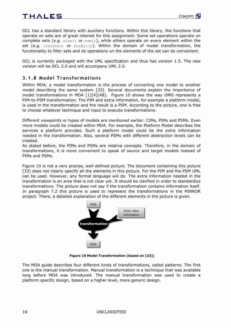
CONCEPTS
OCL has a standard library with auxiliary functions. Within this library, the functions that operate on sets are of great interest for this assignment. Some set operations operate on complete sets (e.g. size() or sum()), while others operate on every element within the set (e.g. iterate() or forAll()). Within the domain of model transformation, the functionality to filter sets and do operations on the elements of the set can be convenient. OCL is currently packaged with the UML specification and thus has version 1.5. The new version will be OCL 2.0 and will accompany UML 2.0.
3.1.8 Model Transformat ions Within MDA, a model transformation is the process of converting one model to another model describing the same system [33]. Several documents explain the importance of model transformations in MDA [1][4][48]. Figure 10 shows the way OMG represents a PIM-to-PSM transformation. The PIM and extra information, for example a platform model, is used in the transformation and the result is a PSM. According to the picture, one is free to choose whatever technique and input to execute transformations. Different viewpoints or types of models are mentioned earlier: CIMs, PIMs and PSMs. Even more models could be created within MDA. For example, the Platform Model describes the services a platform provides. Such a platform model could be the extra information needed in the transformation. Also, several PSMs with different abstraction levels can be created. As stated before, the PIMs and PSMs are relative concepts. Therefore, in the domain of transformations, it is more convenient to speak of source and target models instead of PIMs and PSMs. Figure 10 is not a very precise, well-defined picture. The document containing this picture [33] does not clearly specify all the elements in this picture. For the PIM and the PSM UML can be used. However, any formal language will do. The extra information needed in the transformation is an area that is not clear yet. It should be clarified in order to standardize transformations. The picture does not say if the transformation contains information itself. In paragraph 7.2 this picture is used to represent the transformations in the MIRROR project. There, a detailed explanation of the different elements in the picture is given.
PIMPIM
Some other informationSome other information
transformation
PSMPSM
Figure 10 Model Transformation (based on [33])
The MDA guide describes four different kinds of transformations, called patterns. The first one is the manual transformation. Manual transformation is a technique that was available long before MDA was introduced. The manual transformation was used to create a platform specific design, based on a higher level, more generic design.
UNCLASSIFIED 16

CONCEPTS
The second described technique is the usage of profiles to prepare models for transformation. The terminology used in the profile must of course be platform independent, because it is attached to a PIM. Profiles can be used to mark elements in the PIM. Transformation can then be created based on that marks. The third approach uses patterns and marks. One way of marking a model is the usage of profiles. Patterns can be seen as a kind of transformation. Therefore this approach can be seen as a more generic description of the second one. The last technique is called automatic transformation. Automatic transformations are useful when a set of applications is developed that are similar to each other. In a product line approach, for example, all the artifacts are transformed in a similar way and therefore the same transformation can be used to create all the different applications. These four techniques do not describe all techniques available, they are only examples. Therefore, other approaches are also possible. It is also clear that the techniques do have some overlapping. In fact, it is possible to use a combination of the proposed techniques. This paragraph briefly introduced model transformations. As transformation is a major subject of this assignment, there is a whole chapter dedicated to this subject: Chapter 4 on page 29.
3.1.9 Software eng ineer ing process As MDA is a relative young technology, no definitive model driven development process, based on MDA, is defined. Nevertheless, several books [16][29] describe the possible roles and activities that MDA will need. Some of these roles already exist in current processes such as the Unified Process [30]. These are roles such as business analysts, requirements analysts and software architects. But also new roles are proposed, like application engineers, middleware engineers and deployment engineers. Obviously, at least new tasks within the existing roles will be generated, new roles might be created and existing tasks might disappear. This report does not go into this subject, but focuses mainly on the technical aspects of MDA and transformations.
3 .2 Query / V iews / T rans fo rmat ions In order to standardize queries, views and transformations on models, OMG issued a request for proposals (RFP) for MOF 2.0 Query / Views / Transformations (QVT). Companies and organizations could reply to this request with a proposal for a language. Eventually this process results in a standard for the way queries, views and transformations on models should be expressed. The MDA Technical Perspectives white paper states that relationships between models should be defined at the same level of abstraction as their metamodels [37]. In other words, transformations are expressed in terms of the elements of the metamodel. As all the involved OMG metamodels are defined using MOF, a single transformation language can express transformations between instances of any of these languages. Unfortunately, the RFP for QVT contains no definitions for the terms query, view and transformation. An informal description is given, but proposals must give their own definition in order to be clear about the difference between the terms. In [18] some definition guidelines are given. Queries represent source objects in a homogenous ordered set. Homogenous means that all the objects in the list do have the same type. A query results in a set objects conforming to the constraints specified in the query. Queries cannot create new object instances and do not need to have a link to the source objects. So, changes made to a query result do not have to be propagated to the original source.
UNCLASSIFIED 17

CONCEPTS
A view is, like a query, a representation of source objects. The difference is that views contain heterogeneous objects, so it represents elements with different types. A view of a model can for example be only a part of the model. In [37] a view is described as: “A view is a model that is derived from another model”. Also for views it is not stated explicitly that a link between source and target must be present. Intuitively, changes made on views should be propagated to the original model. Otherwise the view should be defined as read-only. In a transformation, models are created based on other models. A transformation takes the source model as input and creates the target model as output. To sum up, the meaning of queries, views and transformation is rather intuitive; a query selects existing things, a transformation describes how to construct new things from existing things [11] and a view shows part of a model.
3.2.1 QVT Requirements The RFP contains the requirements and guidelines for the people who want to create a proposal. This paragraph summarizes the requirements for QVT.
3.2.1.1 Mandatory Requirements The following requirements are mandatory for a QVT proposal. Every requirement is named. The names are used in the rest of the document to refer to the requirements. Mandatory requirement 1 – Query Language “Proposals shall define a language for querying models. The query language shall facilitate ad-hoc queries for selection and filtering of model elements, as well as for the selection of model elements that are the source of a transformation.” As stated before, the request document does not give a definition of what a query exactly is. The proposal should give a good definition. Queries must be selective and must be able to filter elements. Nothing is said about the constructive properties of queries (see paragraph 5.3.10 Queries). Within transformations, queries can be used to select and filter elements needed in the transformation. It is remarkable that the OMG request for a querying language, because OCL is a query language that is already available and OMG stresses the need to reuse existing standards. Mandatory requirement 2 – Transformation Language “Proposals shall define a language for transformation definitions. Transformation definitions shall describe relationships between a source MOF metamodel S, and a target MOF metamodel T, which can be used to generate a target model instance conforming to T from a source model instance conforming to S. The source and target metamodels may be the same metamodel.” In other words, this requirement states that the transformation is defined in terms of MOF metamodels of the models and that instances of these metamodels are the artifacts that are input and output of transformations. Mandatory requirement 7 also states that the metamodel of the source and target models must be MOF metamodels. Mandatory requirement 3 – MOF Abstract Syntax “The abstract syntax for transformation, view and query definition languages shall be defined as MOF (version 2.0) metamodels.”
UNCLASSIFIED 18

CONCEPTS
OMG requires that the abstract syntax of the transformation language itself is defined using MOF. In order to be completely MOF compliant, a description how to transform the language to XML must also be present in the specification. Paragraph 3.2.2 Abstract versus concrete syntaxes will give more details about the distinction between abstract and concrete syntaxes. Mandatory requirement 4 – Complete information “The transformation definition language shall be capable of expressing all information required to generate a target model from a source model automatically.” This requirement states that the information in the transformation must be adequate to completely generate the target model. It is not specified how to express these information. The typical OMG transformation description, as showed in Figure 10 Model Transformation, shows that “extra information” is used in a transformation. This could be a Platform model, or simply the transformation description itself. Mandatory requirement 5 – View Language “The transformation definition language shall enable the creation of a view of a metamodel.” It is hard to judge if a proposal meets this requirement, because no definition of a view is given. If updates to a view must be propagated to the source model, some kind of link between the source and the view must be created and stored. Mandatory requirement 6 – Declarative Language “The transformation definition language shall be declarative in order to support transformation execution with the following characteristic: Incremental changes in a source model may be transformed into changes in a target model immediately.” This is a strange requirement, because it implies that only declarative languages can support incremental changes. Most recent IDEs for imperative languages continually parse the input typed by a programmer and provide incremental builders. Mandatory requirement 7 – Operate on MOF “All mechanisms specified in Proposals shall operate on model instances of metamodels defined using MOF version 2.0.” OMG has decided that MOF is the common way to define metamodels. Therefore, this requirement must simply be met for a proposal. MOF is used to unify the way metamodels are defined. Because the transformations are defined at the level of the metamodel, one transformation language can be used to express transformations between any models. This requirement is similar to requirement 2. The following is a short informal summary of the mandatory requirements. The numbers between the parentheses correspond to the numbers of the mandatory requirements. The proposals must define a declarative (6) language that can express queries (1), views (5) and transformations (2). The abstract syntax of the proposed language must consist of MOF 2.0 models (3). Transformations are expressed in terms of the elements of the source and target MOF metamodels (2), must have enough information to execute the transformation (4) and are executed on instances of the metamodels (2 and 7).
UNCLASSIFIED 19

CONCEPTS
3.2.1.2 Optional requirements Besides the mandatory requirements a list of optional requirements is presented. These requirements are “nice to have”, but not mandatory for a proposal to conform to this RFP. Optional requirement 1 – Bi-directional Language “Proposals may support transformation definitions that can be executed in two directions. There are two possible approaches: Transformations are defined symmetrically, in contrast to transformations that are defined from source to target. Or, two transformation definitions are defined where one is the inverse of the other.” In order to have an inverse, a transformation must be a bijective mapping. It’s obvious that non-bijective transformations can be specified and therefore, the inverse of a transformation does not always exist. A transformation language that enforces the user to specify bijective transformations is less expressive than transformation languages without that constraint. If the inverse exists and the transformation language conforms to the mandatory requirements, an extra inverse transformation can be specified. The developer must write an extra transformation with the source and target metamodel switched. Optional requirement 2 – Traceability “Proposals may support traceability of transformation executions made between source and target model elements.” In order to be a useful language in the context of MDA, this optional requirement is very important. In the MDA engineering process, changes can be made at different abstraction levels. Especially in the early years of MDA, automated transformations will probably not create the best possible code and optimizations could be performed by hand to improve the PSMs. In order to control the impact of a change in a PSM on the corresponding PIM or not to overwrite changes in a later transformation, link information should be stored. Also for the implementation of views some kind of linking is needed. Updates made to a view must be propagated to the original model. Links and mappings are discussed in more detail in paragraph 7.3 Mappings between models. Optional requirement 3 – Reusability & Extensibility “Proposals may support mechanisms for reusing and extending generic transformation definitions. For example: Proposals may support generic definitions of transformations between general metaclasses that are automatically valid for all specialized metaclasses. This may include the overriding of the transformations defined on base metaclasses. Another solution could be support for transformation templates or patterns.” Transformation reuse and extension enhances the usability of the language. Because UML and MOF are both OO approaches, it is preferable to have typical OO structuring and reuse mechanisms, such as generalization, composition and the distinction between interfaces and implementations. Optional requirement 4 – Transactions “Proposals may support transactional transformation definitions in which parts of a transformation definition are identified as suitable for commit or rollback during execution.”
UNCLASSIFIED 20

CONCEPTS
During the design of a transformation the functionality of often decomposed into several subtransformations. Such a subtransformation does not necessarily result in a well-formed model. Only the composition of the subtransformations result in a well formed model. Therefore it is preferable that the transformation developer can indicate which part of a transformation result in well formed models. It is easy to test if the result of a transformation is well formed by checking it against it’s metamodel. It is hard to identify which part of a transformation execution is responsible for creating invalid model elements or structures. Optional requirement 5 – Additional data “Proposals may support the use of additional data, not contained in the source model, as input to the transformation definition, in order to generate a target model. In addition proposals may allow for the definition of default values for this data.” This optional requirement makes the implementation of mandatory requirement 4 easier, because information not present in the transformation can be taken from additional data. Optional requirement 6 – Allow updates “Proposals may support the execution of transformation definitions where the target model is the same as the source model; i.e. allow transformation definitions to define updates to existing models. For example a transformation definition may describe how to calculate values for derived model elements.” Also if the implementation only allows creation of model, updates can be done. First the transformation is executed and then the target is saved as the source.
3.2.1.3 Issues to be discussed Besides the mandatory and the optional requirements some “issues to be discussed” are proposed. These issues concern reuse of existing standards and some general transformation characteristics. Discussion issue 1 – Reuse CWM “The OMG CWM specification already has a defined transformation model that is being used in data warehousing. Submitters shall discuss how their transformation specifications compare to or reuse the support of mappings in CWM.” Transformations play an important part in data warehousing. Storage, retrieval and presentation of information are all examples of transformations [35]. Therefore, the Common Warehouse Metamodel (CWM) specification describes an abstract syntax for transformations. As the QVT request for proposals also asks for an abstract syntax for transformations, the mechanisms of CWM could be used or at least could be used to gain knowledge about transformations. Discussion issue 2 – Compare to Action Semantics “The OMG Action Semantics specification already has a mechanism for manipulating instances of UML model elements. Submitters shall discuss how their transformation specifications compare to or reuse the capabilities of the UML Action Semantics.” UML AS supports the creation and deletion of UML model elements. AS provides only primitive, elementary operations, such as deletion and creation of a single model element, which could be used to create more complex, composite operations. If a concrete implementation for AS is available, AS could be used to express transformations in.
UNCLASSIFIED 21
CONCEPTS
Discussion issue 3 – Not well-formed input “How is the execution of a transformation definition to behave when the source model is not well-formed (according to the applicable constraints)? Also should transformation definitions be able to define their own preconditions. In that case: What's the effect of them not being met? What if a transformation definition applied to a well-formed model does not produce a well-formed output model (that meets the constraints applicable to the target metamodel)?” While reading and writing models, transformations can simply halt on an error, the simplest solution, but they can also try to execute the transformation, filling in the gaps or changing the wrong elements. From the user point of view, the latter approach is preferable. Discussion issue 4 – Incremental changes “Proposals shall discuss the implications of transformations in the presence of incremental changes to the source and/or target models.” Updates in a source model could result in direct, incremental changes in the target model. Earlier updates to the target model should not be overwritten by the changes. This discussion issue is closely related to optional requirement 2, about traceability between source and target elements.
3.2.1.4 Evaluation criteria Evaluation criterion 1 – Complex transformations “Proposals are preferred that support transformations of relatively high complexity. A simple transformation is for example, a transformation of one instance of "model.Attribute" (the source) to one instance of "uml.foundation.core.Attribute" (the target), both having an attribute called "name". A more complex transformation would be transforming an object oriented model into a relational model including the mapping of the same attribute to different columns for foreign key membership.” It is obvious that trivial transformations are not very interesting for the evaluation of a transformation language. Any proposal should be able to express these easily. The transformation from a typical PIM to a typical PSM is not trivial. The proposals should give an example that shows more complex transformations. Evaluation criterion 2 - Reusability “Proposals shall be preferred that support reusable transformation definitions. For example, by supporting inheritance of transformation rules templates, or patterns.” This criterion is also mentioned in optional requirement 3 and evaluation criterion 3. Reusability is a keyword in the OO world. Reuse of components can potentially reduce the amount of work that needs to be done to create complex systems, or transformation in this case. Evaluation criterion 3 - Extensibility “Proposals shall be preferred that support extendable transformation definitions. In real-world situations users of an "off-the-shelf transformation" want to be able to override or extend aspects of that definition.” If transformation rules conform to this point, they automatically conform to Evaluation Criterion 2, because extension is a kind of reuse.
UNCLASSIFIED 22

CONCEPTS
3.2.2 Abstract versus concrete syntaxes The QVT RFP demands that the abstract syntax of the proposed language is expressed using MOF 2.0. What is an abstract syntax, what is a concrete syntax and what is the relation between those two? No description of abstract syntax is given in the concerning documents. Because the terminology is used several times in the RFP and in the proposals, a clear understanding of the concepts is desirable. This paragraph will illustrate the concepts, by explaining some examples. Abstract and concrete syntaxes are not new concepts. In language development and compiler technology the terminology is well known. The abstract syntax of a language describes the structures that can be used in the language. Abstract syntaxes are used for a long time in computer languages technologies, such as compilers. Parsers parse a program text file and produce a parse tree. Parse trees are constructed according to the abstract syntax. So, parse trees are instances of the abstract syntax.
3.2.2.1 Examples If an abstract syntax is expressed using MOF 2.0, it consists of MOF elements, structured according to the MOF OO structuring mechanisms. In the following example, the following MOF elements are used: MOF Classes and MOF Associations. The attributes within the classes are properties of the MOF Class element. The multiplicity specifications are properties of the MOF Association element. As an example, in OO languages, Classes have Operations and Attributes. This could be represented in an abstract syntax by attaching the Operation and the Attribute to the Class.
ClassName: str
OperationName: str
AttributeName: str
**
Figure 11 MOF Abstract Syntax example
This abstract syntax can’t be used directly by programmers. To express something in the language, one needs a concrete syntax. The concrete syntax is the way programmers see and use the language. Therefore, it is also called the “surface" syntax. It is the syntax that is visible to the user. In theory, the concrete language can be any language that uses the semantics available in the abstract syntax. Consequently, different concrete syntaxes can belong to the same abstract syntax. Concrete syntaxes can be visual or textual. In this example a textual representation is used. An example of a concrete syntax is a grammar in Extended Backus Naur Form (EBNF). For the previous abstract syntax a concrete syntax could like like:
<class> ::= class STRING { <attr>* <opr>* } <attr> ::= attribute STRING ; <opr> ::= operation STRING ;
Code fragment 1 EBNF example
UNCLASSIFIED 23

CONCEPTS
Non-terminals are enclosed by brackets (< and >), terminals are printed bold and the keyword STRING indicates that the user can specify a string. In this case the string will be an identifier. Programs could be written using this grammar. The following is a simple example.
Class MyClass { attribute myAttribute; attribute anotherAttribute; operation myOperation; }
Code fragment 2 Program example
This example program could be parsed into an abstract syntax tree (AST), conforming to the abstract syntax. The abstract syntax defines the structure of the AST’s. Elements from the concrete syntax are mapped to elements of the abstract syntax. In the example, the Class is the root element in the AST. The Attributes and the Operation are all children of the Class.
ClassName: “myClass”
OperationName: “myOperation”
AttributeName: “anotherAttribute”
AttributeName: “anotherAttribute”
Figure 12 AST example
An abstract syntax is used because it provides a notation independent way to represent languages. The concrete syntax is then defined by mapping the notation to the abstract elements [40]. Concluding informally, the concrete syntax of a language is the way programmers look the language. The abstract syntax is the way compilers look at the language.
3.2.2.2 Formal approach In [52] the relation between an abstract language and a concrete language is represented in a more formal way. This representation clarifies the relation between the concepts. This document is referenced from [28]. A language L is represented as a five tuple consisting of a concrete syntax C, an abstract syntax A, a semantics domain S, semantic mappings Ms and syntactic mappings Mc. This is presented as:
},,,,{ cs MMSACL = Equation 1 A language
A concrete syntax describes the way the models can be represented. The abstract syntax defines the meaning, concepts, relationships and integrity constraints available in the language. It determines all the correct syntactic sentences that may be expressed in the concrete syntax. The semantics describe the meaning of constructs in the language. The mapping Mc assigns concrete syntactic constructs to the elements of the abstract syntax. Mapping Ms assigns semantics to the same abstract syntax.
UNCLASSIFIED 24

CONCEPTS
SAM s →: Equation 2 Semantic mapping
CAM c →: Equation 3 Concrete syntactic mapping
Thus, elements from the abstract syntax are mapped to both elements from the semantic syntax and the concrete syntax.
3.2.3 QVT proposa ls The RFP for QVT has resulted in six “first revised proposals”. This paragraph briefly describes the contents of the proposals. The data is extracted from [18] and from the submission documents themselves. In this paragraph for every proposal, one of the proposing companies is used to refer to their proposal. For example, when the DSTC proposal is mentioned it refers to the proposal from DSTC and IBM. If the proposed language has an own name, that name is used.
3.2.3.1 Alcatel/Softeam/TNI-Valiosys/Thales (openQVT) Because this assignment evaluates the language proposed in this document, it is described in more detail then the others. Chapter 5 on page 39 is completely dedicated to the language presented in the proposal: The Transformation Rule Language (TRL) [1].
3.2.3.2 DSTC/IBM According to the DSTC approach there are little differences between queries, views and transformations [11]. However, DSTC emphasizes that views must have a direct relation to their source(s). This relation must guarantee that changes in the views are propagated to the original models and visa versa. Transformations do not necessarily need these relationships. To create a relation between elements from different models the concept of tracking relationship is introduced. In a tracking relationship, an instance of a link between the interrelated objects describes the functional dependency. Queries select elements from the source model and return sets of the selected objects. Hence, the results can only show elements already in the source model and cannot construct new structures. Accordingly, these queries are called selective and not constructive. The proposed language is pure declarative and does not describe how to construct the output. As the language is a logic-based language, it can be hard to understand for those not experienced in using that formalism. Nevertheless, for those who have used the logic-based constructs from for example SQL (SELECT, FORALL, EXISTS, NOT IN, etc.) or PROLOG, the language will be very intuitive. To indicate on which part of the source model a transformation applies, the concept of pattern definition is introduced. Pattern definitions are named constructs describing patterns in the source model. One pattern can be used several times in different transformations. As a proof of concept, a prototype of the language, based on the F-Logic compiler, is available.
UNCLASSIFIED 25
CONCEPTS
In conclusion the main differences and similarities between DSTC’s proposal and TRL are discussed. DSTC proposes selective queries, while TRL uses constructive queries as they are considered as special transformations. DSTC proposes a pure declarative language. TRL also has imperative concepts and therefore TRL is classified as a hybrid language. According to [9], both languages have a relational approach to transformations.
3.2.3.3 Compuware Corporation/SUN Microsystems Compuware proposes XMOF as a transformation language [8]. XMOF is based on MOF and OCL. Because these techniques alone are not expressive enough to specify transformations, some extensions to these techniques are proposed. XMOF is a pure declarative language with symmetrical transformations. Queries expressed in XMOF are OCL queries. Views and transformations have an own grammar. XMOF introduces the concept of ports. Ports are parts of models that can be transformed. Transformations are expressed between ports. As a proof of concept, the authors indicate that the concepts of XMOF are extracted from the tool OptimalJ. The similarity between XMOF and TRL is that both are kind of extensions to the existing language OCL. The big difference is the declarative approach of XMOF versus the hybrid approach of TRL.
3.2.3.4 Tata Consultancy Services/Artisan Software/Kinetum/Kings College/University of York
This proposal is submitted under the name QVT partners. In this paragraph this name is used to refer to this specification. The QVT partners’ proposal contains a language that creates relations between source and target models, without specifying how to achieve the transformation. Remarkable in this proposal is the graphical notation available for transformations. Pictograms can be used to compose transformations, so transformations can be modeled using visual tools. To improve scalability also a textual representation is available. The proposal distinguishes between relations and mappings. Relations are declarative and mappings are operational implementations. This approach that separates between a declarative specification and an imperative implementation was also used in TRL.
3.2.3.5 Interactive Objects Software GmbH/Project Technology Inc. The language proposed in this document is called AIM [22]. No explanation of the name is contained in the document. AIM is a declarative language. It describes model patterns. Transformation rules consist of two patterns, the source and the target pattern. To execute transformations, the engine must search for pattern matches in the source and create the corresponding patterns in the target. Because the language is declarative, the specification of a transformation does not include information about how to search the source model for certain patterns. This is something that must be implemented in the transformation engine. The approach resembles transformations based on graph rewriting systems, explained in paragraph 4.2.3 on page 32.
3.2.3.6 Kennedy Carter Kennedy Carter stresses that the UML 1.5 already contains enough functionality to express transformations on models. The document refers to the AS that was introduced in UML 1.5. Because AS can be used to specify complete and executable models, it can be used to specify (executable) models of transformations and queries. The proposal does not contain examples, grammars or detailed specifications.
UNCLASSIFIED 26

CONCEPTS
Current implementations of AS, as the Action Semantics Language (ASL) [7], are imperative languages. Therefore, this proposal violates the mandatory requirement that the language should be declarative. In short, Kennedy Carter proposes ASL as a language to model systems and also model transformations.
3 .3 Summary This chapter introduced some key concepts of MDA: models, metamodels, viewpoints, CIMs, PIMs and PSMs. In addition several MDA related technologies were explained: UML, MOF, OCL and model transformations in general. Next, the RFP for QVT was introduced, by describing and explaining the mandatory requirements, the optional requirements, the discussion issues and the evaluation criteria. Then, the difference between abstract and concrete syntaxes was explained. Finally the different proposals for QVT were discussed and compared briefly. This chapter introduced the concept of model transformations. The next chapter goes more deeply into the subject of transformations.
UNCLASSIFIED 27

CONCEPTS
UNCLASSIFIED 28

TRANSFORMATIONS
4 Transformations
A transformation is defined (according to Webster online) as “The operation of changing one configuration or expression into another in accordance with a mathematical rule”, or more specific to languages “an operation that converts one grammatical string into another”. In MDA, “a transformation is the process of converting one model to another model of the same system”. This chapter describes transformations as they are used in MDA and QVT. To evaluate TRL a number of desired characteristics for transformations is presented. This list can be compared with the transformations of TRL to evaluate the language. First, some transformation concepts are explained.
4 .1 Trans format ions i n MDA In MDA, transformations can be defined between models. One or more source models can be transformed into one or more target models [33]. Although MDA does not prescribe a way to specify or to execute these transformations (yet), the RFP for QVT contains requirements that prescribe a certain structure for transformations. This structure is represented in Figure 13. The requirements were described in paragraph 3.2.1. The figure below shows the relationship between several artifacts involved in a PIM-to-PSM, UML-to-UML transformation.
Is an instance of Dependency
input
PIM (UML model)
PIM (UML model)
PSM(UML model)
PSM(UML model)
UMLmetamodel
UMLmetamodel
UMLmetamodel
UMLmetamodel
TransformationExecution
TransformationExecution
TransformationModel
TransformationModel
TransformationMetamodel
TransformationMetamodel
MOFMOF
input output
Data flow
Figure 13 PIM-to-PSM, UML-to-UML Transformations
The solid arrows indicate instance of relationships, the dashed arrows indicate dependencies and the dotted arrows represent data flows. So, PIM and PSM UML models are instances of the UML metamodel, which in turn is an instance of the MOF. Both rectangles with the UML metamodel represent the same one UML metamodel. The transformation model is an instance of a transformation metamodel. In order to be a QVT compliant, the transformation metamodel must be an instance of the MOF. The representation of the transformation is a block arrow that points from the source to the target of the transformation. This representation is intentionally different from the other elements in the figure. The transformation execution is an executable instance of a transformation model; it is a kind of process.
UNCLASSIFIED 29

TRANSFORMATIONS
The transformation model is the specification of the transformation. This transformation is dependent of the metamodels of the source and the target models. Transformations are expressed in terms of the elements of these metamodels. Therefore there are dependencies between the transformation model and the both metamodels. The transformation needs additional information about the target platform. In the case study, described in chapter 7 and 8, this information is the knowledge of DDS. This information is specified in a human readable way, in a specification document. Thus, it can’t be used directly by the transformation. As a solution, this information is programmed into the transformation. In MDA the source and the target metamodel do not have to be the same. In the mini Threat Evaluation case study the metamodels are just slightly different. In both cases the metamodel is the UML metamodel, but they have different profiles. Profiles are extensions to the metamodels and therefore the metamodels are not identical. In order to evaluate a transformation language, one must know the properties of the language. In [9] a classification for model transformation languages is proposed. Using this classification, choices made for a specific transformation language can be made explicit. A classification of a language can serve as a basis for the evaluation of the language.
4 .2 Trans format ion Techn iques There are several ways to execute transformations. Some of the techniques are already available and some don’t have implementations yet. The transformation approaches that are discussed are XSLT transformations, tool-specific transformations, graph based transformations and finally the usage of a transformation DSL to specify transformations.
4.2.1 XMI XSLT approach The XMI XSLT approach is based on several existing technologies to perform transformations. This chapter will first introduce the four enabling techniques XML, XML schema, XMI and XSLT. Next the combination of the techniques is explained to show how to execute a transformation.
4.2.1.1 The techniques: XML, Schema, XMI and XSLT The eXtensible Markup Language (XML) is a technique to standardize the formatting of data. An XML file contains elements. Elements are enclosed by a start and an end tag and can contain other elements. Every element has a name and can have attributes. The content of an element is placed between the tags. The data is represented as text and is placed in a Unicode text file. The following code shows a small XML sample.
<car make=”Audi”> <color> Black </color>
<price> 5500 </price> </car>
Code fragment 3 XML sample
The example shows the XML representation of a car. The make of the car is stored in an attribute. The colour and the price are stored as elements. The example gives an impression of the usage of XML. This report will not describe XML in detail. Information about XML is widely available [6].
UNCLASSIFIED 30
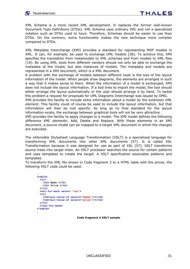
TRANSFORMATIONS
XML Schema is a more recent XML development. It replaces the former well-known Document Type Definitions (DTDs). XML Schema uses ordinary XML and not a specialized notation such as DTDs used to have. Therefore, Schemas should be easier to use than DTDs. On the contrary, extra functionality makes the new technique more complex compared to DTDs. XML Metadata Interchange (XMI) provides a standard for representing MOF models in XML. It can, for example, be used to exchange UML models [38]. To achieve this, XMI specifies the translation from metamodels to XML schemas and from models to XML files [19]. By using XMI, tools from different vendors should not only be able to exchange the metadata of the model, but also instances of models. The metadata and models are represented in a XMI document, which is a XML document. A problem with the exchange of models between different tools is the loss of the layout information of the model. When people draw diagrams, the elements are arranged in such a way that it makes sense to them. When the information of a model is exchanged, XMI does not include the layout information. If a tool tries to import the model, the tool should either arrange the layout automatically or the user should arrange it by hand. To tackle this problem a request for proposals for UML Diagrams Interchange was issued by OMG. XMI provides the facility to include extra information about a model by the extension XML element. This facility could of course be used to include the layout information, but that information will then be tool specific. As long as no final standard for the layout information exists, the exchange between graphical tools will not be very attractive. XMI provides the facility to apply changes to a model. The XMI model defines the following difference XML elements: Add, Delete and Replace. With these elements in an XMI document, a source model can be mapped to a target XML document in which the changes are executed. The eXtensible Stylesheet Language Transformation (XSLT) is a specialized language for transforming XML documents into other XML documents [57]. It is called XSL Transformation because it was designed for use as part of XSL [57]. XSLT transforms source trees into target trees. An XSLT processor searches the source for certain patterns and uses templates to create the target. A XSLT specification associates patterns and templates. To transform the XML file shown in Code fragment 3 to a HTML table with the prices, the following XSLT code could be used.
… <table> <tr> <th> Make </th> <th> Price </th> </tr> <xsl:for-each select “car”> <tr> <td><xsl:value-of select=”@make”/></td> <td><xsl:value-of select=”price”/></td> </tr> </xsl:for-each> </table> …
Code fragment 4 XSLT sample
UNCLASSIFIED 31

TRANSFORMATIONS
4.2.1.2 Model transformations Now the technologies are explained it is not hard to imagine how a transformation using XSLT is performed. Modelers can use their XMI supporting modeling tool to create the source models. The result can be stored as an XMI file. This is an ordinary XML file. Transformation developers can create a XSLT document that describes the transformation. An XSLT processor can now be used to transform the XML file with the source to an XML file with the target. A modeling tool can now be used to import the result XMI file and create a visual representation of the target model. The problem with this approach is the readability of the transformations. XSLT documents are just like XML files not intended to be read by humans. The advantage of this approach is the availability of XMI supporting tools and XSLT engines.
4.2.2 Tool dependent t ransformat ions Currently, several tools can execute model transformations in their own way. To demonstrate such a transformation, a PIM-to-PSM transformation was written in the language J [50]. The transformation could be executed on a PIM and generated a corresponding PSM. In this approach the knowledge of the platform is hard coded into the transformation. Once the transformation for a platform is specified, it can be used for any PIM to create the corresponding PSM. Hard coding the knowledge of the platform into the transformation is not a desired way to express the target platform. The created transformation is described in Appendix C Transformations expressed in J. Other modeling tools also have similar capabilities of model transformations. Rational’s XDE provides Java API that can be used to manipulate and transform models [21]. ArcStyler from Interactive Objects also has the ability to execute model transformations. [23].
4.2.3 Graph based transformat ions Graph Rewriting Systems (GRS) or Graph Transformation (GT) systems use a technique based on graphs to perform transformations. Graph theory is not a recent development, but it has been a research topic since about 1970. Research on graph theory and transformations is therefore mature and much information about it is available. To use a graph based technique in MDA a model must first be represented as a graph. As most models in MDA are defined using UML as modeling language, UML must first be mapped to a graph. Graphs have less distinct elements than UML models. A graph contains nodes and vertices, which can optionally be decorated with a label.
UNCLASSIFIED 32

TRANSFORMATIONS
Target graph
1 2
3 4
1 2
345
in out
A TransformationA rule
Replace withpattern
Search forpattern
1
2 3
1
23
4
Another rule
…
Source graph
Figure 14 A graph transformation
GRSes use patterns inside modifying rules. In [4] every rule contains exactly two patterns, the left hand side (lhs) and the right hand side (rhs). The lhs graph describes the occurrence of a sub graph in the source graph and the rhs graph describes the replacement pattern. The algorithm for the transformations examines the source graph and every occurrence of the lhs in the source is then replaced by the rhs. A simplified version of this process is illustrated in Figure 14 above. In [52] an extra functionality is added to this model by adding structural constraints on the sub graphs found in the source graph. With these extra conditions transformations can be expressed in a more precise way. The language used to express the constraints is the Object Constraint Language (see 3.1.7). One of the problems of graph transformations is the efficiency of the patterns matchers. If no extra information is given to such a tool the recognition of patterns is a time consuming operation. One of the advantages of graph-based transformations is the presentation of transformations. Because (especially a subset of) UML can easily be expressed as a graph, transformations can also be expressed using UML. A complete system using graph transformation was developed as a prototype [28]. In that prototype the user interface shows UML. The transformation engine uses graphs “under the hood”.
4.2.4 DSL for t ransformat ions To implement a transformation and create a transformation model, any appropriate programming language can be used. Transformations can also be expressed in a Domain Specific Language (DSL). The domain in this case is the “transformation domain”. Several studies show that the usage of a DSL can reduce costs and increase the understandability of programs [10] [31]. All replies to the RFP for QVT, except the one from Kennedy Carter, contain a DSL for transformations. The documents propose languages that can express transformations only. As a consequence, the users of the language have to learn the DSL. As the languages are only concerned with transformations their syntaxes should be small and easy to understand.
UNCLASSIFIED 33

TRANSFORMATIONS
4.2.5 Genera l -purpose language with AP I A general-purpose programming language could be used with a specific API to manipulate model elements and models. Examples of this approach are available for Java [15][21] and for Python [15]. If programmers have knowledge of the programming language, only a little extra generic transformation knowledge is needed to implement a transformation.
4 .3 So f tware Qua l i ty Measurement The purpose of this thesis is to evaluate TRL. To evaluate the useability oof the language, the tooling that is provided with the language can be evaluated. Quality of the supporting software influences the practical usability of the language. Quality of software is hard to measure or to compare to the quality of other software. In order to guide this software evaluation, the ISO/IEC 9126 Software engineering – Product quality [24][25] provides a structured approach to software evaluation. Software evaluation can be performed at three distinct levels. The internal level investigates the quality factors that can be observed in static artifacts, such as software design documents or the programming code. The external level observes the behavior of the system as a black box. External observations are done during execution of the software that is under investigation. Obviously the internal quality factors somehow influence the external quality factors. The third level is the quality in use. This is the highest level and it describes the quality factors of a product, as they are visible to the end user. The end used can be persons who use the software, but also persons why maintain the software. Therefore the type of end users must be specified during evaluation. The quality of a software product can be divided in different categories: the software characteristics. These characteristics can be subdivided in subcharacteristics. The product quality document [24] contains a complete list of all characteristics with corresponding subcharacteristics. Because not all characteristics are relevant for every product, one must choose a subset that is used for the evaluation. The following table shows the characteristics that are evaluated in this report.
Characteristics
Sub characteristics
Definitions
Suitability The capability of the software product to provide an appropriate set of functions for specific tasks and user objectives.
Accurateness The capability of the software product to provide the right or agreed results or effects with the needed degree of precision.
Interoperability The capability of the software product to interact with one or more specified systems. Fu
nct
ional
ity
Compliance The capability of the software product to adhere to standards conventions or regulations in laws and similar prescriptions relating to functionality.
UnderstandabilityThe capability of the software product to enable the user to understand whether the software if suitable, and how it can be used for particular tasks and conditions of use.
Learnability The capability of the software product to enable the user to learn its application. U
sabili
ty
Operability The capability of the product to enable the user to operateand control it.
UNCLASSIFIED 34

TRANSFORMATIONS
Efficiency Time behaviour The capability of the software product to use appropriate response and processing times and throughput rates whenperforming its function, under stated conditions.
Portability Installability The capability of the software product to be installed in a specified environment.
Table 2 Product Quality External Characteristics
Beside the external quality characteristics, the following quality in use characteristics are evaluated. Name Description Effectiveness The capability of the software product to enable users to achieve
specified goals with accuracy and completeness in a specified context of use.
Productivity The capability of the software product to enable users to expend appropriate amount of resources in relation to the effectiveness achieved in a specified context of use.
Satisfaction The capability of the software to satisfy users in a specified context of use.
Table 3 Quality in Use Characteristics
For every element in Table 2 and Table 3 a metric is introduced and measured for the TRL compiler in paragraph 9.4 on page 98.
4 .4 Des i red proper t i e s o f t rans format ions The former section described the characteristics of the TRL supporting software. This section describes the desired properties of transformations and the specification of transformations. Transformations are the actions of mapping some source model to some target model. The specification of transformations is the way transformations are expressed by a transformation designer. Most desired properties apply to both the execution and specification of transformations. To evaluate a given implementation of transformations, the implementation can be judged by the presence of the elements mentioned in this chapter. The naming and description of the properties are derived from [1], [16], [29] and [48].
4.4.1 Tuneabi l i ty Tuneability is the ability to influence the transformation execution. When using an automated transformation process, users will likely want to influence the transformation process. In the near future, MDA transformation tools will probably not be very sophisticated. So, user influence can have a positive effect on transformation results. In the early days of compilers people used similar techniques to “help” the compiler build optimal code. Nowadays, compilers are smart enough to generate quality code without user help. In fact, most developers don’t check the generated code. The first way to influence transformations is to manually influence each transaction. This option gives the user great flexibility, but results in a great amount of work for the developer. Especially when the models are big. One of the ideas of MDA was to eliminate human interference in non-creative development process, like programming. Full manual influence does defiantly not encapsulate this idea.
UNCLASSIFIED 35

TRANSFORMATIONS
The second option is the ability to put conditions on transformations. Transformation rules will only be executed when the condition is evaluated as true. Using this technique, modelers can say for example: “If a source class is stereotyped as <<vehicle>> generate a target class in the target model”. As a third option, parameterized transformation could be used. Transformations could then be specified in a more generic way. When a transformation is used it most get the required parameters to realize the specialized transformation. Finally, the modeler could get the possibility to put additional information in a model to make certain transformations possible. When the modeler for example wants to create a condition on a transformation, but the model does not contain enough information to express the condition, the modeler must add information to the model.
4.4.2 Traceabi l i ty Traceability is the ability to resolve which target elements are derived from which source element. In traditional software development the only “truth” was the code. When the software needed to be adjusted, changes to the code were made. The program was generated from the code and updates to the design models were optional. MDA uses several artifacts to develop software. The PIM contains the platform independent business model, the PSM contains the derived platform specific model and the source code files contain the generated code. Developers could apply changes to any of these artifacts. To be able to handle such situations, elements from one model should be traceable to elements from other models in some way. In that case, a tool is able to show problems that arise or can indicate inconsistencies in the different models. If there exists an ongoing relation between a source s and a target t, the models are called dependent. For dependent models it is possible to guarantee consistency. Instead of traceability, one can use a top down approach. Changes can only be made to the source. Generated models cannot be changed by hand. Such an approach is, especially in the early days of MDA, not a desirable approach.
4.4.3 Incrementa l cons i s tency Especially in the early years of MDA most tools will not completely generate software from models, but the tools will generate some of the software and the developers have to fill in the gaps in the code. Incremental consistency is the ability to perform transformations that do not overwrite existing elements. A typical situation in software development is the adaptation of existing software. In MDA a project contains CIMs, PIMs, PSMs and code. The different artifacts contain different levels of detail. Some information in the PIM is not available in the CIM, some information in the PSM not in the PIM, etcetera. When developers make changes to the code, fill in the gaps, and changes are made to one of the models, then the changes in the code must not be overwritten during the code generation. Repeated application should not overwrite any information introduced in the target model. Within the MIRROR project the term “conservative generation” is used. To realize incremental consistency, traceability is required.
UNCLASSIFIED 36
TRANSFORMATIONS
4.4.4 Bi -d i rect iona l i ty Another desired property of a transformation could be bi-directionality, the ability to perform transformations in both ways. This could be achieved by using one transformation, which is it’s own inverse, one transformation for which the transformation engine can derive the inverse or it could consist of two distinct transformation that are each other’s inverse. In my view, bi-directionality should be omitted from the desired features of transformations. Not all transformations are bijective functions, so it’s impossible to guarantee that the inverse transformation exists. If bi-directionality is needed, it is possible to define two separate transformations that are each other’s inverse.
4.4.5 Express ive power Expressive power describes the ability to express certain things in a language. Transformation languages should provide the capability to express transformations. The used language can be any language that has enough capabilities to express transformations. Transformation specific languages such as TRL, J, ATL or XSLT can be used, but also general-purpose language such as Java, C or Python. For the general-purpose languages some kind of API is needed to access the model elements. Most transformation specific languages already contain such constructs.
4.4.6 Readabi l i ty Readability is the capability of the language to be understood by the user. The description of transformations should be readable if it’s expressed as textual code. Transformations visualized as a picture are probably more intuitive to understand. However, graphical representations tend to have problems representing big transformations. Because the transformations contain domain specific knowledge, domain experts should be able to create them.
4.4.7 Portabi l i ty Transformations should be executable on any tool on any platform a user wants to use for a project. Portability is the capability to be transferred from one environment to another [24].
4.4.8 Durabi l i ty Durability is the ability to endure for a certain amount of time. New versions of tools should be able to execute transformations generated in older versions of a tool. Projects will have the most financial benefits from using MDA in the maintenance stage of a project [49]. This stage can last for several decades for some software products and therefore older transformations should still be executable.
4.4.9 Compos i t ion capabi l i ty Composition capability is the capacity to compose transformations from other, existing transformations. Most tools provide a mechanism to create composite transformations, but the used transformations have to be other transformations build in the same tool. The combination of transformations from several tools leads to more flexibility.
UNCLASSIFIED 37
TRANSFORMATIONS
4.4.10 Open standards based An agreed, open and unified standard for the specification and execution of transformations will help tool builders to interoperate with other tools in a well defined way.
4 .5 Pend ing p rob lems Although the principle of transformations is not very new, there are still problems that are very hard to address that must be solved. This paragraph describes some problems. Is it possible to check if a set of rules is consistent? If one rule depends on the result of another one, the rule must be sure that the other rule is already executed and the resulting model elements are available. Another question that is hard to solve for a certain transformation is: does the transformation result in a valid output for every valid input? Is a set of rules complete to cover all legal input models? Is the result of a transformation deterministic, or can the transformation have different results? These questions are not answered yet for transformations. Accordingly most tools ignore these things and leave the responsibility of the transformation quality to the transformation developer.
4 .6 Summary This paragraph gave a detailed description of transformations in the context of MDA. Several techniques for transformation executions are discussed, including the one that is used in this assignment, a DSL for transformations. In order to check if a language is adequate for the expression of transformations, one must know which properties are desirable for a transformation language. This chapter contains a list with such properties. This list is used during the evaluation of TRL.
UNCLASSIFIED 38

TRANSFORMATION RULE LANGUAGE
5 Transformation Rule Language
This chapter describes the Transformation Rule Language (TRL). The first paragraph introduces TRL by describing some typical constructs and terminology. Next, the structure of the different artifacts in the specification is explained. A more detailed description of the language is given in 5.3, Classification of TRL. The description is given by summing up the features of the language. This way of classification provides insight in the design choices that were made for TRL. Furthermore, knowledge of the language’s features also clarifies the applicability of the language.
5 .1 TRL I n t roduc t ion As described in paragraph 3.2.3.1 Alcatel/Softeam/TNI-Valiosys/Thales, TRL was proposed as a QVT language [1]. Obviously, the primary purpose of the language is to express queries, views and transformations. TRL queries are expressed using OCL, TRL views are treated as specialized transformations and as a consequence the TRL specification mainly focuses on transformations. In TRL, queries, views and transformations are grouped into units. Units are the ‘packages’ of the language. They contain, among others, transformation rules. Two types of rules are available in TRL. On the one hand, TRL has conformance-based rules. These are declarative descriptions of transformation. Such rules can describe the desired result of a transformation, but the rules do not have the semantics of how to execute the transformation. Stated differently, conformance-based rules can be considered as some kind of invariants or post conditions for transformations. On the other hand, operational rules are imperative rules that do describe how to execute a transformation. The relationship between operational and conformance-based rules is that an operational rule can conform to conformance-based ones. TRL has the notion of model types. A model type is similar to a metamodel of a model. It describes the available elements for a model. As transformations in TRL are described in terms of the metamodels (see Figure 10 Model Transformation), the compiler must know what elements can be used in a transformation description. By declaring the model types, the compiler knows what elements can be used. In addition, model types can be configured. Configuration of a model type means that it is modified in order to express transformations in a more convenient way. One could for example declare intermediate structures that are used as placeholders during transformations. The TRL specification [1] states that TRL is an extension to OCL. OCL is a declarative constraint language. Pure OCL expressions are side effect free and can therefore not be used for model modification and thus not for transformations. TRL extends OCL with constructs that do have side effects, such as creation and assignments.
5 .2 Language s t ruc tu re The proposal of, among others, Thales TRT contains the description of an abstract syntax of transformations and two concrete implementations corresponding to the proposed abstract syntax of a transformation language [1]. The distinction between abstract and concrete syntaxes was explained in paragraph 3.2.2.
UNCLASSIFIED 39

TRANSFORMATION RULE LANGUAGE
5.2.1 TRL’s Abstract Syntax The abstract syntax of TRL describes what kind of structures can be expressed in the language. It describes how parse trees derived from TRL programs must be structured. MOF 2.0 is used to specify the syntax and it is displayed as a series of UML diagrams with textual descriptions. The specification is structured with TRL modules. The specification approach is a top down one. The first diagrams in the documents describe the structuring of generic elements. These diagrams depict concepts that are not specific to transformations. The elements in these diagrams are for example: Element, Object, Parameter, Property, Operation, etc. The first diagram that contains data specific to the transformation domain is the “Module Categories” diagram. A module is a unit that can perform some kind of action. In TRL 3 types of units are available: QueryUnit, TransformationUnit and ViewUnit. Transformations and views are similar actions. In the TRL metamodel a generalization is used to indicate that a view is a transformation. Within units, there are three kinds of operations: Activator operations, OperationalRules and Helper operations. The Activator is the entry point in a transformation. When a transformation contains an activator (the operation named go() in TRL), then the transformation will start executing the instructions contained in the body of that operation. Transformations without an activator can be used by other transformations. The operational rules describe the actions that must be performed to execute the transformation. Expressions written in the operational rules express something like: “For every source element of type Class A, create a target element of class B”. Helper operations are operations with side effects that can be used to perform actions. Helper operations increase the expressive power of the transformation rules.
5.2.2 TRL’s Concrete Syntax TRL’s specification contains, beside the abstract syntax, a concrete syntax corresponding to the abstract syntax. The concrete syntax defines the language called Transformation Rule Language (TRL). The concrete syntax is presented as a grammar in EBNF form. It is possible to create your own concrete syntax in any appropriate language (J, Java, Python, etc.), corresponding to the same metamodel. In the proposal, another rule language is provided to demonstrate that multiple concrete languages can correspond to the same abstract syntax. The relationship between abstract and concrete syntaxes in TRL is illustrated in Figure 15.
UNCLASSIFIED 40

TRANSFORMATION RULE LANGUAGE
..........rule {}create c:Class.........
* ? ( ) ::=* ? ( ) ::=
TRLTRL
JJJavaJava
APIAPI
....................
rule {}create c:Class.........
rule {}create c:Class.........
TransformationMetamodel
Abstract syntaxConcrete syntax
Source files using the concrete syntaxes
M3
M2
M1
MOF
TransformationModels
Parse trees
Instance of corresponding to conforming to
Programs
(E)BNF
Grammar
Figure 15 Transformation Rule Language overview
This picture represents the artifacts that are used specific in TRL. It doesn’t mean that abstract syntaxes are always in MOF and concrete syntaxes in EBNF. In fact, it is possible to create concrete syntaxes with MOF and abstract ones in EBNF. However, in TRL the concrete syntaxes use EBNF and the abstract one uses MOF. For TRL a prototype compiler was developed by France Telecom. The compiler reads TRL text documents and produces “programs” that contain transformations. These programs can be executed on models. The compiler is described in detail in chapter 6, about the tooling.
5.2.3 Implementat ion of TRL In the current TRL compiler, TRL source code is translated to Python source code. Thus, to execute TRL, actually the Python code is executed. The transformation to Python might explain the similarities of TRL to other imperative or procedural languages. The rules of TRL are similar to the functions of other languages. TRL’s units are similar to the classes of the other language.
5 .3 C las s i f i ca t ion o f TRL The TRL language is a Domain Specific Language (DSL) for model transformations. In [9] a classification method for transformation approaches is given. In [18] all the QVT proposals are compared and also classified. In this paragraph, TRL is classified according to these classification documents. The purpose of language classification is to make the design decisions explicit. In this document, TRL is classified by describing its features. These features are illustrated using feature diagrams. Feature diagrams indicate which features are available in a language by showing a box with the textual description of the feature. Besides, the concepts used in the figures are explained in plain text.
UNCLASSIFIED 41
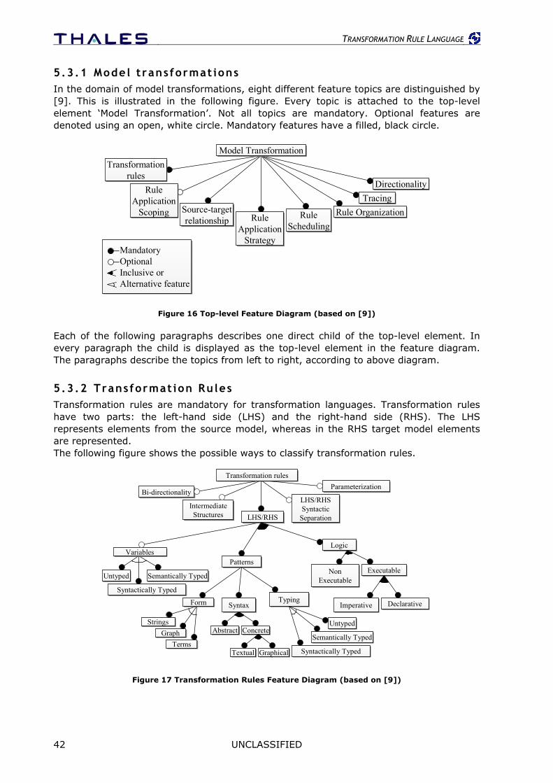
TRANSFORMATION RULE LANGUAGE
5.3.1 Model t ransformat ions In the domain of model transformations, eight different feature topics are distinguished by [9]. This is illustrated in the following figure. Every topic is attached to the top-level element ‘Model Transformation’. Not all topics are mandatory. Optional features are denoted using an open, white circle. Mandatory features have a filled, black circle.
MandatoryOptionalInclusive orAlternative feature
MandatoryOptionalInclusive orAlternative feature
DirectionalityDirectionality
RuleApplication
Strategy
RuleApplication
Strategy
Source-targetrelationship
Source-targetrelationship
TracingTracingRule
ApplicationScoping
RuleApplication
Scoping
Model TransformationModel Transformation
Rule OrganizationRule OrganizationRuleScheduling
RuleScheduling
Transformationrules
Transformationrules
Figure 16 Top-level Feature Diagram (based on [9])
Each of the following paragraphs describes one direct child of the top-level element. In every paragraph the child is displayed as the top-level element in the feature diagram. The paragraphs describe the topics from left to right, according to above diagram.
5.3.2 Transformat ion Rules Transformation rules are mandatory for transformation languages. Transformation rules have two parts: the left-hand side (LHS) and the right-hand side (RHS). The LHS represents elements from the source model, whereas in the RHS target model elements are represented. The following figure shows the possible ways to classify transformation rules.
ExecutableExecutable
Syntactically TypedSyntactically Typed
PatternsPatterns
StringsStrings
SyntaxSyntax
AbstractAbstract ConcreteConcrete
TextualTextual
TypingTypingImperativeImperative DeclarativeDeclarative
NonExecutable
NonExecutable
LHS/RHSLHS/RHS
LogicLogic
IntermediateStructures
IntermediateStructures
Transformation rulesTransformation rulesParameterizationParameterization
LHS/RHSSyntactic
Separation
LHS/RHSSyntactic
Separation
Bi-directionalityBi-directionality
UntypedUntyped Semantically TypedSemantically Typed
VariablesVariables
GraphGraphTermsTerms
FormForm
GraphicalGraphical Syntactically TypedSyntactically Typed
UntypedUntyped
Semantically TypedSemantically Typed
Figure 17 Transformation Rules Feature Diagram (based on [9])
UNCLASSIFIED 42

TRANSFORMATION RULE LANGUAGE
Figure 18 shows the features of transformation rules specific for TRL. This diagram is thus an instance of Figure 17. After the figure, the elements are described individually.
VariablesVariables
SyntacticallyTyped
SyntacticallyTyped
PatternsPatterns
FormForm
StringString
SyntaxSyntax
AbstractAbstract ConcreteConcrete
TextualTextual
TypingTyping
SyntacticallyTyped
SyntacticallyTyped
ExecutableExecutable
ImperativeImperative DeclarativeDeclarative
NonExecutable
NonExecutable
LHS/RHSLHS/RHS
LogicLogic
IntermediateStructures
IntermediateStructures
Transformation rulesTransformation rulesParameterizationParameterization
LHS/RHSSyntactic
Separation
LHS/RHSSyntactic
Separation
Bi-directionalBi-directional
Figure 18 Transformation Rules for TRL
Bi-directional Conformance based transformation rules are bi-directional. In contrast, operational based rules are unidirectional. Thus, in TRL only some of the rules are bi-directional. Because the operational part of TRL is considered as the most important part, TRL is generally classified as a unidirectional language. Intermediate structures In TRL, an existing model type can be configured to be more convenient for a particular transformation. One of the possible ways to configure a model type is by defining intermediate data structures such as classes or derived properties. These intermediate structures can be used as auxiliary structures and can simplify and clarify the expression of transformations. LHS/RHS The LHS and the RHS are mandatory features of a transformation rule. In TRL the LHS and the RHS are not clearly separated, because terms from both sides are used in a specification. For example, the following code illustrates the mixing of source and target elements within one rule.
rule create "setter" Operationfrom Attribute() {
name := "set_" + self.name;
…}
SourceSource
TargetTarget SourceSource
TargetTarget
Figure 19 LHS/RHS mixture in TRL
The variable self is not required in the code. When it is not present in the code, the result is name := “set_” + name; In which the first reference to name is different from the second one.
UNCLASSIFIED 43

TRANSFORMATION RULE LANGUAGE
Variables In TRL local variables and context variables are available. Context variables are created implicitly. Examples are this, self, result and iter. Variables are statically typed, which means that they are an instance of some kind of metamodel element. In other words, variables are of a certain type. This way of typing is common for programming languages typing and is used in numerous popular languages such as Java, C and Visual Basic. TRL’s type system merges the type systems from Essential MOF (EMOF) and from OCL. The resulting type system has primitive types as well as metaclasses of the metamodels. Patterns A pattern is used to select elements from the source model. In TRL patterns have a textual representation, using a subset of OCL to specify the pattern. For patterns in TRL both an abstract and a concrete syntax are given. The concrete syntax is the textual representation of TRL. Logic The logic part of the feature diagram does not represent exactly the way logic is used in TRL. The reason this representation is used, is because [9] specifies that it must be modeled this way. A better representation for TRL would be one with the ‘declarative’ box attached to the ‘non executable’ box. In TRL two types of rules can be used. First, conformance based mappings that are pure declarative. These mappings can be checked during transformation execution, but in TRL these mappings have no executable semantics. Second, operational rules describe executable transformations in an imperative way. These rules do have executable semantics and can therefore be executed to perform a transformation. Syntactic separation Syntactic separation means that the syntax of LHS elements is different from that of RHS elements. In TRL certain operations are not allowed on LHS. For example, a value cannot be assigned to a LHS element, unless the purpose of the unit is updating. Parameterization TRL transformation rules can declare parameters that must be passed when the rule is called.
5.3.3 Rule Appl icat ion Scoping Rule application scoping is an optional topic of features. It can be used to restrict parts of the source or of the target during transformation execution. In TRL, no mechanism is provided to exclude parts of the source or of the target model. Selection or filtering criteria can be specified on source model elements using patterns, but this is checked for every element in the source.
Rule Application ScopingRule Application Scoping
SourceSource TargetTarget
Figure 20 Rule Application Scoping feature diagram (based on [9])
UNCLASSIFIED 44

TRANSFORMATION RULE LANGUAGE
The absence of scoping could lead to performance problems during transformation execution. In software specifications, models can become large. In that case, the performance of transformation execution would improve if it is only executed on certain parts of the model.
5.3.4 Relat ionship between Source and Target In model transformations, models are created or updated based on existing models. This paragraph describes the relationship between the source and the target in TLR.
In-Place(In Source)In-Place
(In Source)
Existing TargetExisting Target
UpdateUpdate
Source-Target RelationshipSource-Target Relationship
New TargetNew Target
DestructiveDestructive Extension onlyExtension only
Figure 21 Relationship between Source and Target feature diagram (based on [9])
In-Place(In Source)In-Place
(In Source)
Existing TargetExisting Target
UpdateUpdate
Source-Target RelationshipSource-Target Relationship
New TargetNew Target
Extension onlyExtension only
Figure 22 Relationship between Source and Target for TRL
New Target TRL transformation can create target models from scratch. Existing Target TRL transformations can update existing models. This automatically implies that the In-Place feature is present. Although the TRL specification describes delete functionality very briefly, it is not available in the current compiler implementation.
5.3.5 Rule Appl icat ion Strategy Rule application strategy describes the order in which rules are executed. Three main strategies can be distinguished.
Rule Application StrategyRule Application Strategy
DeterministicDeterministic Non-DeterministicNon-Deterministic InteractiveInteractive
ConcurrentConcurrent One-PointOne-Point
Figure 23 Rule Application Strategy Feature Diagram (based on [9])
UNCLASSIFIED 45
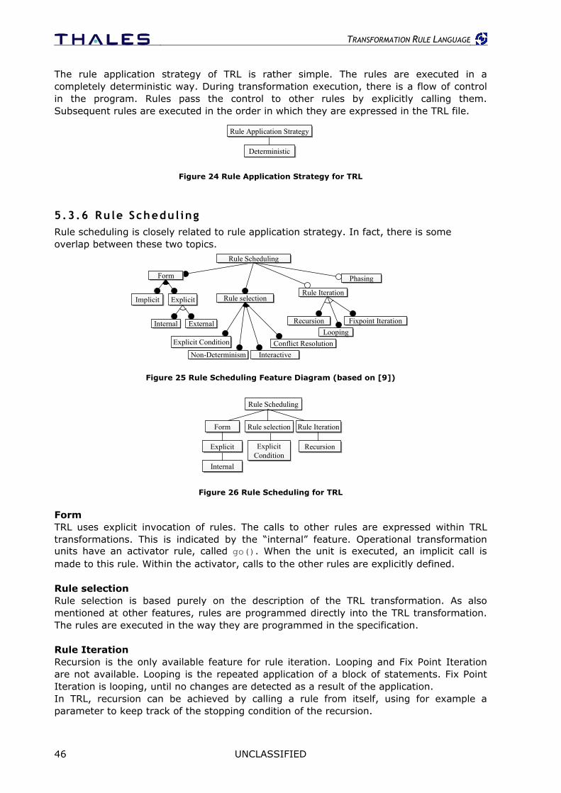
TRANSFORMATION RULE LANGUAGE
The rule application strategy of TRL is rather simple. The rules are executed in a completely deterministic way. During transformation execution, there is a flow of control in the program. Rules pass the control to other rules by explicitly calling them. Subsequent rules are executed in the order in which they are expressed in the TRL file.
Rule Application StrategyRule Application Strategy
DeterministicDeterministic
Figure 24 Rule Application Strategy for TRL
5.3.6 Rule Schedul ing Rule scheduling is closely related to rule application strategy. In fact, there is some overlap between these two topics.
Rule SchedulingRule Scheduling
FormForm
Rule IterationRule IterationExplicitExplicit
InternalInternal
Rule selectionRule selection
Explicit ConditionExplicit Condition
RecursionRecursion
ImplicitImplicit
ExternalExternal
Conflict ResolutionConflict ResolutionNon-DeterminismNon-Determinism InteractiveInteractive
LoopingLoopingFixpoint IterationFixpoint Iteration
PhasingPhasing
Figure 25 Rule Scheduling Feature Diagram (based on [9])
Rule SchedulingRule Scheduling
FormForm Rule IterationRule Iteration
ExplicitExplicit
InternalInternal
Rule selectionRule selection
ExplicitConditionExplicit
ConditionRecursionRecursion
Figure 26 Rule Scheduling for TRL
Form TRL uses explicit invocation of rules. The calls to other rules are expressed within TRL transformations. This is indicated by the “internal” feature. Operational transformation units have an activator rule, called go(). When the unit is executed, an implicit call is made to this rule. Within the activator, calls to the other rules are explicitly defined. Rule selection Rule selection is based purely on the description of the TRL transformation. As also mentioned at other features, rules are programmed directly into the TRL transformation. The rules are executed in the way they are programmed in the specification. Rule Iteration Recursion is the only available feature for rule iteration. Looping and Fix Point Iteration are not available. Looping is the repeated application of a block of statements. Fix Point Iteration is looping, until no changes are detected as a result of the application. In TRL, recursion can be achieved by calling a rule from itself, using for example a parameter to keep track of the stopping condition of the recursion.
UNCLASSIFIED 46

TRANSFORMATION RULE LANGUAGE
5.3.7 Rule Organizat ion Rule organization describes the way rules can be ordered into packages and composed from existing rules. Many well know programming techniques focus heavily on reuse and modularity.
Organizational structureOrganizational structure
InheritanceInheritance
Reuse mechanismsReuse mechanisms
ModularityMechanismsModularity
Mechanisms
Source-OrientedSource-Oriented
Rule OrganizationRule Organization
Logical CompositionLogical Composition Target-orientedTarget-oriented
IndependentIndependent
Figure 27 Rule Organization Feature Diagram (based on [9])
Organizationalstructure
Organizationalstructure
InheritanceInheritance
Reuse mechanismsReuse mechanismsModularityMechanismsModularity
Mechanisms
Source-OrientedSource-Oriented
Rule OrganizationRule Organization
Figure 28 Rule Organization for TRL
Modularity mechanisms In TRL rules are packaged into modules, called units. Three kinds of units can be distinguished: Query, view and transformation units. Reuse mechanisms In TRL, reuse is available at different levels. Units can inherit from other units. This is called unit inheritance. In unit inheritance the child can reuse and override operations defined in the parent unit. This way of inheritance is well known from OO programming languages. It is the coarse grained version of inheritance in TRL. Figure 29 shows two units with an inheritance relation. The parent unit defines two methods: a() and b(). Unit B inherits from A and redefines method b(). The sequence diagram shows the way a call is forwarded within the units.
unitA
unitB
unitAunitB
aaa()
b()
b()b
Figure 29 Unit inheritance
UNCLASSIFIED 47

TRANSFORMATION RULE LANGUAGE
Rules can also inherit from each other. Rule inheritance has different semantics than unit inheritance. When a rule inherits from another rule, the parent rule is executed after the init section of the child rule. After that, the body of the child rule is executed. The sequence diagram for a chain of inheritance is shown in Figure 30.
ruleA
ruleB
ruleC
ruleC ruleAruleBinit
initinitmain
main
main
end
end
end
Figure 30 Rule inheritance
Rule inheritance propagates the call to rules to the parent rules. This way of inheritance is the fine-grained inheritance mechanism. Organizational structure Rules in TRL are expressed in terms of elements of the metamodel of the source model. The activator starts calling a rule on the top-level element of the model. The rule for the top-level element calls rules for elements that it contains, etc. Accordingly, TRL is called source-oriented or source-driven.
5.3.8 Traceabi l i ty L inks A traceability link is a link that connects a source and a target element. Using this technique, it is possible to find target elements that are derived from specific source elements. Traceability is necessary to provide incremental consistency, which is explained in paragraph 4.4.3 on page 36. Traceability is a very important aspect of transformations, because in real-world situations the target will not be completely generated from the source every time. Changes will be made to the target and to the source and the tooling must check if there are no conflicts.
ControlControl
ModelModel
Dedicated SupportDedicated Support
StorageLocationStorage
Location
ManualManual
TracingTracing
SeparateSeparate
All RulesAll Rules
AutomaticAutomatic
SourceSource TargetTarget Selected RulesSelected Rules
Figure 31 Tracing Feature Diagram (based on [9])
UNCLASSIFIED 48

TRANSFORMATION RULE LANGUAGE
ControlControl
Dedicated SupportDedicated Support
TracingTracing
All RulesAll Rules
AutomaticAutomaticSeparateSeparate
Storage LocationStorage Location
Figure 32 Tracing Feature for TRL
The TRL prototype does maintain links between source and target elements. These links are only accessible during transformation and are not stored to be used afterwards.
5.3.9 Direct iona l i ty Directionality describes the way in which transformations can be executed. Transformations that can transform only from source to target are called unidirectional. Transformations that can go forwards and backwards are called bi-directional.
Bi-directionalBi-directionalUnidirectionalUnidirectional
Bi-directional rulesBi-directional rules
DirectionalityDirectionality
Complementary partsComplementary parts
Figure 33 Directionality Feature Diagram (based on [9])
Bi-directionalBi-directionalUnidirectionalUnidirectional
Bi-directional rulesBi-directional rules
DirectionalityDirectionality
Figure 34 Directionality for TRL
Although TRL is has some bi-directional features, it is mainly a unidirectional language. The bi-directional features are provided by conformance-based rules, but these rules cannot be executed. Of course it is possible to provide an inverse rule of another operational rule, if it exists, but there is no special TRL construct to define this.
5.3.10 Quer ies While [9] concentrates purely on the transformation domain, [18] also describes the other aspects involved in QVT: queries and views. Because in the TRL views are treated as a special kind of transformation, only queries are considered here. Queries can be declarative or imperative. Because TRL uses OCL for queries, it is classified as declarative. Queries can also be constructive or pure selective. Selective means that only existing elements from models can be selected. On the other hand, constructive queries can also create elements that do not exist in a model. OCL queries are constructive and therefore TRL queries are also constructive.
UNCLASSIFIED 49

TRANSFORMATION RULE LANGUAGE
To illustrate the concept of constructive queries, consider the Structured Query Language (SQL) query: SELECT 10 FROM aTable. This query will return a set with integers with values of 10, while these integers need not to exist in the table aTable. The set is thus not selected, but constructed.
5 .4 Summary This chapter introduced TRL. After the general concepts of the language and the structure of the TRL specification were explained, the features of the language were illustrated. Feature diagrams were used to explicitly show the features of the language.
UNCLASSIFIED 50
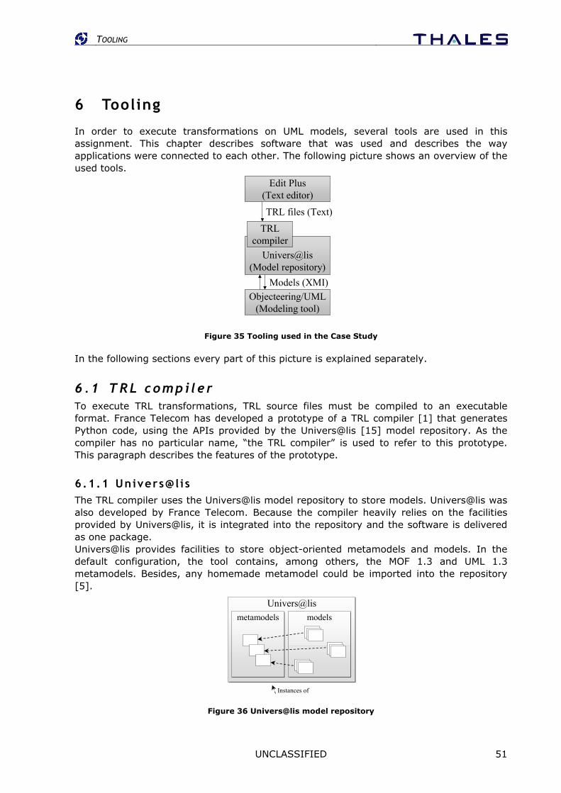
TOOLING
6 Tooling
In order to execute transformations on UML models, several tools are used in this assignment. This chapter describes software that was used and describes the way applications were connected to each other. The following picture shows an overview of the used tools.
Univers@lis(Model repository)
Edit Plus(Text editor)
TRLcompiler
Objecteering/UML(Modeling tool)
Models (XMI)
TRL files (Text)
Figure 35 Tooling used in the Case Study
In the following sections every part of this picture is explained separately.
6 .1 TRL compi l e r To execute TRL transformations, TRL source files must be compiled to an executable format. France Telecom has developed a prototype of a TRL compiler [1] that generates Python code, using the APIs provided by the Univers@lis [15] model repository. As the compiler has no particular name, “the TRL compiler” is used to refer to this prototype. This paragraph describes the features of the prototype.
6.1.1 Univers@l i s The TRL compiler uses the Univers@lis model repository to store models. Univers@lis was also developed by France Telecom. Because the compiler heavily relies on the facilities provided by Univers@lis, it is integrated into the repository and the software is delivered as one package. Univers@lis provides facilities to store object-oriented metamodels and models. In the default configuration, the tool contains, among others, the MOF 1.3 and UML 1.3 metamodels. Besides, any homemade metamodel could be imported into the repository [5].
Univers@lisUnivers@lismetamodelsmetamodels modelsmodels
Instances of
Figure 36 Univers@lis model repository
UNCLASSIFIED 51

TOOLING
The picture above illustrates the way artifacts in Univers@lis are stored. To save a model in the repository, the metamodel must be present in the tool. As stated before, some default metamodels are available. The metamodel of TRL is also available. This provides the TRL compiler the facility to store the information from a TRL source file in a TRL syntax tree. TRL transformations are executed on models that reside in the repository.
6.1.1.1 The repository The Univers@lis tool provides several APIs to perform actions on models. It has APIs for both for Java and for Python. These two general-purpose, OO languages were chosen to make the models fully accessible with non-proprietary programming tools. In contrast some other modeling tools use dedicated, proprietary languages to access the models such as J for UML/Objecteering. The tool provides reflective and tailored APIs. The reflective API provides a generic capability to traverse models. In this way, models with different metamodels can be traversed in a similar way. Thus, the traversal is independent of the used metamodel. Tailored APIs use the role names from the metamodel. As a result, the usage of tailored interfaces is more straightforward compared to the generic interfaces. But, traversal using such APIs is not independent of the used metamodel. The creation of the tailored API's is based on a number of rules that creates the methods that can be used for the navigation. So tailored APIs are derived from metamodels in a specified way. Univers@lis provides a number of different textual outputs. The textual outputs describe the elements that are in the model. As a result, the number of elements in a typical textual representation can be large. The available output formats are XMI, XMI+, JMI (Java-like Metadata Interchange), PMI (Python-like Metadata Interchange) and CTF (Compiled Textual Format). XMI can be used to interchange data between different tools. XMI representation is not very readable for humans. To make the models more readable some other output formats were defined. XMI+, JMI and PMI are all languages used to describe a model in a more human readable way. XMI+ is a simplified version of XMI, which has a more compact representation of the same data. JMI and PMI describe the models the same way as XMI+, but they use the typical notation of Java and Python respectively. Finally, the Compiled Textual Format is the internal format used within the Univers@lis model repository. Again this representation contains the same information as the other output formats, but this representation focuses on the way the model repository stores the models.
6.1.1.2 User interface Univers@lis is implemented using Python. Thus, the repository consists of a number of Python script files. These scripts can be accessed using a web-interface or can be executed directly from the command line. The web-interface is accessed using an ordinary web browser. The browser provides the facilities the represent a graphical user interface.
UNCLASSIFIED 52

TOOLING
Figure 37 Univers@lis Web Interface (screenshot)
Figure 37 shows an example screen. The interface shows the possible actions that can be done on a model repository.
6.1.1.3 Tools Univers@lis provides several auxiliary tools. One of them is a web viewer that generates a textual representation of models for a HTML browser. The output format can be any of the available textual output formats and the output uses syntax highlighting to improve readability. Furthermore, the tool can import and export models from Rational Rose 98, Objecteering v4 and works with tools that support the OMG XMI standard for import and export of models. The auxiliary tools are all implemented as scripts and can be executed from the command line and some also from the graphical user interface.
6.1.2 Metamodels In MOF, models have metamodels. In Univers@lis, every model also has a metamodel. The repository contains for example the UML metamodel. Thus, UML models can be stored in the tool.
6.1.3 Bases A base is a named set of models with the same metamodel. Base is a shorthand notation for “Model database”. It is a repository providing persistent storage for models. Within bases, identification of models is achieved using the hierarchical naming space.
6.1.4 The compi ler The TRL compiler provides the facility to compile TRL transformations. The result of the compilation process is intermediate Python code. The code describes transformations expressed in terms of the metamodels of the source and the target models. It uses the Python API from Univers@lis. This API provides facilities to generate and modify models.
UNCLASSIFIED 53
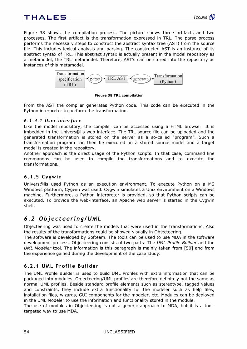
TOOLING
Figure 38 shows the compilation process. The picture shows three artifacts and two processes. The first artifact is the transformation expressed in TRL. The parse process performs the necessary steps to construct the abstract syntax tree (AST) from the source file. This includes lexical analysis and parsing. The constructed AST is an instance of its abstract syntax of TRL. This abstract syntax is actually present in the model repository as a metamodel, the TRL metamodel. Therefore, AST’s can be stored into the repository as instances of this metamodel.
Transformationspecification
(TRL)
Transformationspecification
(TRL)parseparse TRL ASTTRL AST generategenerate Transformation
(Python)Transformation
(Python)
Figure 38 TRL compilation
From the AST the compiler generates Python code. This code can be executed in the Python interpreter to perform the transformation.
6.1.4.1 User interface Like the model repository, the compiler can be accessed using a HTML browser. It is imbedded in the Univers@lis web interface. The TRL source file can be uploaded and the generated transformation is stored on the server as a so-called “program”. Such a transformation program can then be executed on a stored source model and a target model is created in the repository. Another approach is the direct usage of the Python scripts. In that case, command line commandos can be used to compile the transformations and to execute the transformations.
6.1.5 Cygwin Univers@lis used Python as an execution environment. To execute Python on a MS Windows platform, Cygwin was used. Cygwin simulates a Unix environment on a Windows machine. Furthermore, a Python interpreter is provided, so that Python scripts can be executed. To provide the web-interface, an Apache web server is started in the Cygwin shell.
6 .2 Objec teer ing /UML Objecteering was used to create the models that were used in the transformations. Also the results of the transformations could be showed visually in Objecteering. The software is developed by Softeam. The tools can be used to use MDA in the software development process. Objecteering consists of two parts: The UML Profile Builder and the UML Modeler tool. The information is this paragraph is mainly taken from [50] and from the experience gained during the development of the case study.
6.2.1 UML Prof i le Bui lder The UML Profile Builder is used to build UML Profiles with extra information that can be packaged into modules. Objecteering/UML profiles are therefore definitely not the same as normal UML profiles. Beside standard profile elements such as stereotype, tagged values and constraints, they include extra functionality for the modeler such as help files, installation files, wizards, GUI components for the modeler, etc. Modules can be deployed in the UML Modeler to use the information and functionality stored in the module. The use of modules in Objecteering is not a generic approach to MDA, but it is a tool-targeted way to use MDA.
UNCLASSIFIED 54

TOOLING
6.2.1.1 UML Profiles UML is a general-purpose modeling language. To adopt the language to a specific domain, the UML language can be extended with UML profiles. The following figure represents the relationship between several profiles. The top-level element is the representation of the metamodel of UML 2.0, which is in this case provided by the Objecteering tools, the Objecteering/UML metamodel. The other elements are extensions to this profile. These extensions can be downloaded, purchased or developed.
EJB (standard)
CORBA (standard)
…
MyEJB1 MyEJB2
Thales specific
UML 2.0
Figure 39 Relationship between profiles
A profile has three constructions to extend standard UML: stereotypes, tagged values and constraints. Using stereotypes, information about a model can be added to the model. Stereotype names are enclosed between << and >> tags. For example, if a class must be persistent in a system. The stereotype <<persistent>> can be added to the profile and the UML model can contain elements decorated with the <<persistent>> tag. The model now contains extra information about the persistency of elements. Tagged values are simply values that are tagged with a name. An example makes the idea of tagged values clear. If an element in the model contains a list of certain elements, the list can be implemented using hashing or it can be sequentially stored. The tag StorageMode can then be used with the values HashMode and SequentialMode. To indicate that an element must use the hashing technique {StorageMode(HashMode)} or StorageMode: HashMode can be added to the element. The representation of tagged values is not standardized, but the idea of tagged values is straightforward. Constraints can be added to a model to ensure for example correctness or readability of a model. Constraints can be expressed in any available constraint language, but OMG proposes the Object Constraint Language, or OCL as the standard constraint language. Once a profile is created it must be packaged into an Objecteering Module. This module can then be delivered to the UML modeler. Then the modeler also knows the stereotypes and other functionality create in the profile builder.
6.2.2 UML modeler UML modeler is a graphical UML modeling tool that uses the information stored in the UML Profile. The tool can be used to create UML models. The tool can also execute the actions expressed in the Profile using J. The tool uses extra information packaged in the used MDA Components. For example the UML to Java profile contains Java specific GUI windows with typical java elements such as public, protected, static, synchronized etc.
UNCLASSIFIED 55
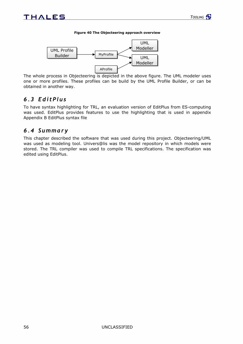
TOOLING
Figure 40 The Objecteering approach overview
The whole process in Objecteering is depicted in the above figure. The UML modeler uses one or more profiles. These profiles can be build by the UML Profile Builder, or can be obtained in another way.
MyProfile UML
Modeller
UML Modeller
AProfile
UML Profile Builder
6 .3 Ed i tP lu s To have syntax highlighting for TRL, an evaluation version of EditPlus from ES-computing was used. EditPlus provides features to use the highlighting that is used in appendix Appendix B EditPlus syntax file
6 .4 Summary This chapter described the software that was used during this project. Objecteering/UML was used as modeling tool. Univers@lis was the model repository in which models were stored. The TRL compiler was used to compile TRL specifications. The specification was edited using EditPlus.
UNCLASSIFIED 56

DESCRIPTION OF THREAT EVALUATION
7 Description of Threat Evaluation
To evaluate TRL, a case study was carried out. This chapter introduces the context of the case study. After the introduction, some characteristics of the Data Distribution Service (DDS) are explained to motivate the usage of transformations in the case. Then an overview of the processes and artifacts used in the MIRROR project is presented. Finally, the need for mapping models is discussed and several possible approaches to achieve mappings are presented. Beside the information in this chapter, Appendix A contains a set of additional examples concerning the case study.
7 .1 I n t roduct ion In order to make decisions in a combat situation, it is important to have a clear view of the strategic and tactical situation of your own ship and other forces. Therefore, ships can be equipped with all kinds of sensors such as search radars, tracking radars, antennas, optical sensors, infrared sensors, etc. One can imagine that modern, state-of-the-art sensors collect an immense amount of data every second. In order to extract usable information from it, the data must be processed. The Combat Management System (CMS) is the integrated system that controls sensors, weapons, communication and navigation of a ship. One of the tasks of the CMS is to provide a view of the surrounding of a ship. Anti Air Warfare (AAW) is a component within a CMS that is concerned with the defense against air targets. Because AAW considers fast moving, high threatening items such as missiles and fighter aircrafts, this type of warfare is called critical. Threat Evaluation (TE) is a subcomponent of a CMS; it is a component of AAW. To determine if an object is a threat to the ship, TE analyses it and assigns a potential treat value to it. Within the system, an object detected by sensors is called a track. Thus, TE assigns threat values to tracks. A threat value is a numeric representation of the estimated danger of a track. The threat value is calculated based on the main course, the main speed, time to go to the own ship, the potential damage according to intelligence, etc. After the threat values are assigned to the tracks, they can be ordered and presented to the Warfare Officer. The officer can now decide if certain tracks should be engaged or not, based on the presented information. Using this approach an officer can focus on the items that are most dangerous for the ship and thus need the most attention. The MIRROR project is building a TE component using MDA. One of the techniques used in the development is a transformation from a PIM to a PSM. This case study is concerned with this transformation. TRL is used to specify and execute the transformation. The position of this transformation within the complete development process is explained in paragraph 7.1.4 and further.
7.1.1 Project Background The Future Combat Management System (FCMS) is a product under development by Thales. FCMS is Thales’ next generation CMS and it is built to replace the current CMS TACTICOS. TACTICOS has been a successful product based on the SPLICE architecture that is currently used in as many as twelve different navies worldwide [20]. MIRROR TNNL applies MDA to build a TE component for FCMS. TE is a subsystem of the complete AAW component within FCMS. The purpose of the usage of MDA is the evaluation of MDA for the development of “real-world” products.
UNCLASSIFIED 57
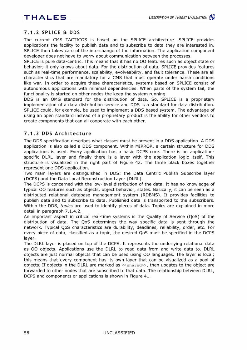
DESCRIPTION OF THREAT EVALUATION
7.1.2 SPL ICE & DDS The current CMS TACTICOS is based on the SPLICE architecture. SPLICE provides applications the facility to publish data and to subscribe to data they are interested in. SPLICE then takes care of the interchange of the information. The application component developer does not have to worry about communication between the processes. SPLICE is pure data-centric. This means that it has no OO features such as object state or behavior; it only knows about data. For the distribution of data, SPLICE provides features such as real-time performance, scalability, evolveability, and fault tolerance. These are all characteristics that are mandatory for a CMS that must operate under harsh conditions like war. In order to acquire these characteristics, systems based on SPLICE consist of autonomous applications with minimal dependencies. When parts of the system fail, the functionality is started on other nodes the keep the system running. DDS is an OMG standard for the distribution of data. So, SPLICE is a proprietary implementation of a data distribution service and DDS is a standard for data distribution. SPLICE could, for example, be used to implement a DDS based system. The advantage of using an open standard instead of a proprietary product is the ability for other vendors to create components that can all cooperate with each other.
7.1.3 DDS Archi tecture The DDS specification describes what classes must be present in a DDS application. A DDS application is also called a DDS component. Within MIRROR, a certain structure for DDS applications is used. Every application has a basic DCPS core. There is an application-specific DLRL layer and finally there is a layer with the application logic itself. This structure is visualized in the right part of Figure 42. The three black boxes together represent one DDS application. Two main layers are distinguished in DDS: the Data Centric Publish Subscribe layer (DCPS) and the Data Local Reconstruction Layer (DLRL). The DCPS is concerned with the low-level distribution of the data. It has no knowledge of typical OO features such as objects, object behavior, states. Basically, it can be seen as a distributed relational database management system (RDBMS). It provides facilities to publish data and to subscribe to data. Published data is transported to the subscribers. Within the DDS, topics are used to identify pieces of data. Topics are explained in more detail in paragraph 7.1.4.2. An important aspect in critical real-time systems is the Quality of Service (QoS) of the distribution of data. The QoS determines the way specific data is sent through the network. Typical QoS characteristics are durability, deadlines, reliability, order, etc. For every piece of data, classified as a topic, the desired QoS must be specified in the DCPS layer. The DLRL layer is placed on top of the DCPS. It represents the underlying relational data as OO objects. Applications use the DLRL to read data from and write data to. DLRL objects are just normal objects that can be used using OO languages. The layer is local; this means that every component has its own layer that can be visualized as a pool of objects. If objects in the DLRL are marked as <<shared>>, then updates to the object are forwarded to other nodes that are subscribed to that data. The relationship between DLRL, DCPS and components or applications is shown in Figure 41.
UNCLASSIFIED 58
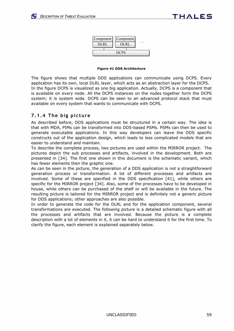
DESCRIPTION OF THREAT EVALUATION
ComponentComponent
DCPSDCPS
DLRLDLRLComponentComponent
DLRLDLRL…
Figure 41 DDS Architecture
The figure shows that multiple DDS applications can communicate using DCPS. Every application has its own, local DLRL layer, which acts as an abstraction layer for the DCPS. In the figure DCPS is visualized as one big application. Actually, DCPS is a component that is available on every node. All the DCPS instances on the nodes together form the DCPS system; it is system wide. DCPS can be seen to an advanced protocol stack that must available on every system that wants to communicate with DCPS.
7.1.4 The b ig p icture As described before, DDS applications must be structured in a certain way. The idea is that with MDA, PIMs can be transformed into DDS-based PSMs. PSMs can then be used to generate executable applications. In this way developers can leave the DDS specific constructs out of the application design, which leads to less complicated models that are easier to understand and maintain. To describe the complete process, two pictures are used within the MIRROR project. The pictures depict the sub processes and artifacts, involved in the development. Both are presented in [34]. The first one shown in this document is the schematic variant, which has fewer elements then the graphic one. As can be seen in the picture, the generation of a DDS application is not a straightforward generation process or transformation. A lot of different processes and artifacts are involved. Some of these are specified in the DDS specification [41], while others are specific for the MIRROR project [34]. Also, some of the processes have to be developed in house, while others can be purchased of the shelf or will be available in the future. The resulting picture is tailored for the MIRROR project and is definitely not a generic picture for DDS applications; other approaches are also possible. In order to generate the code for the DLRL and for the application component, several transformations are executed. The following picture is a detailed schematic figure with all the processes and artifacts that are involved. Because the picture is a complete description with a lot of elements in it, it can be hard to understand it for the first time. To clarify the figure, each element is explained separately below.
UNCLASSIFIED 59
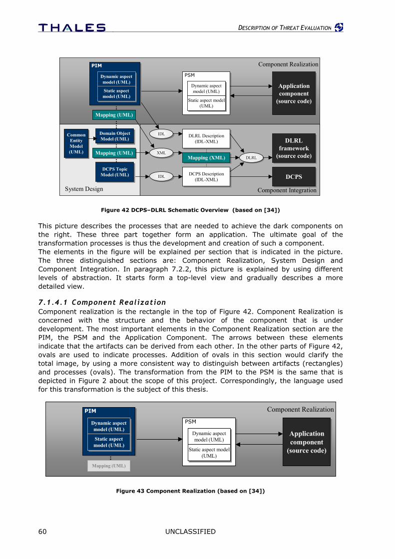
DESCRIPTION OF THREAT EVALUATION
PSMPSM
Dynamic aspect model (UML)
Dynamic aspect model (UML)
Static aspect model (UML)
Static aspect model (UML)
Application component
(source code)
Application component
(source code)
Common Entity Model (UML)
Common Entity Model (UML)
Domain Object Model (UML)
Domain Object Model (UML)
DCPS Topic Model (UML)DCPS Topic
Model (UML)
Mapping (UML)Mapping (UML)
Mapping (UML)Mapping (UML)
DLRL Description(IDL-XML)
DLRL Description(IDL-XML)
DCPS Description (IDL-XML)
DCPS Description (IDL-XML)
DLRLDLRLXMLXML
IDLIDL
Mapping (XML)Mapping (XML)
IDLIDL
DLRL framework
(source code)
DLRL framework
(source code)
DCPSDCPS
PIMPIM
Dynamic aspect model (UML)
Dynamic aspect model (UML)
Static aspect model (UML)Static aspect
model (UML)
Component Realization
Component IntegrationSystem Design
Figure 42 DCPS–DLRL Schematic Overview (based on [34])
This picture describes the processes that are needed to achieve the dark components on the right. These three part together form an application. The ultimate goal of the transformation processes is thus the development and creation of such a component. The elements in the figure will be explained per section that is indicated in the picture. The three distinguished sections are: Component Realization, System Design and Component Integration. In paragraph 7.2.2, this picture is explained by using different levels of abstraction. It starts form a top-level view and gradually describes a more detailed view.
7.1.4.1 Component Realization Component realization is the rectangle in the top of Figure 42. Component Realization is concerned with the structure and the behavior of the component that is under development. The most important elements in the Component Realization section are the PIM, the PSM and the Application Component. The arrows between these elements indicate that the artifacts can be derived from each other. In the other parts of Figure 42, ovals are used to indicate processes. Addition of ovals in this section would clarify the total image, by using a more consistent way to distinguish between artifacts (rectangles) and processes (ovals). The transformation from the PIM to the PSM is the same that is depicted in Figure 2 about the scope of this project. Correspondingly, the language used for this transformation is the subject of this thesis.
PSMPSM
Dynamic aspect model (UML)
Dynamic aspect model (UML)
Static aspect model (UML)
Static aspect model (UML)
Application component
(source code)
Application component
(source code)
Mapping (UML)Mapping (UML)
PIMPIM
Dynamic aspect model (UML)
Dynamic aspect model (UML)
Static aspect model (UML)Static aspect model (UML)
Component Realization
Figure 43 Component Realization (based on [34])
UNCLASSIFIED 60

DESCRIPTION OF THREAT EVALUATION
The PIM is the platform independent design of a system. It contains the elements that are needed in the application, but it doesn’t have DDS specific constructs. These DDS platform specific constructs are (automatically) introduced in the PIM-to-PSM transformation. The PSM contains the same information as the PIM, but the PSM is DDS-oriented. The PIM and the PSM are both subdivided into two parts: the static aspect model and the dynamic aspect model. The static aspect model describes the static structure of the model elements. This structure is represented using UML class diagrams. The dynamic aspect represents the dynamic behavior of the elements modeled in the static aspect model. This behavior is represented in UML sequence diagrams and in programming code. After the transformation, the PSM doesn’t contain enough information to generate a complete working application yet. Thus, Functionality must be added to the PSM. This enrichment of the PSM is not illustrated in this picture, but it is visible in Figure 46 on page 63. From the PSM and the additional information, the source code for the application can be generated. This source code can then be compiled to an executable file. This compilation process is not depicted in the figure. The resulting executable file is not a standalone application, but it relies heavily on the DLRL and DCPS code that is also generated for this application. That generation process is described in the paragraph about the component integration, paragraph 7.1.4.3.
7.1.4.2 System Design System design contains large, detailed objects models, representing the concepts known in the system. The Common Entity Model (CEM) identifies all the known domain entities that are part of FCMS with their attributes and definitions. The CEM is used to get an unambiguous vocabulary for all involved people. Therefore it can be seen as a system glossary. The Domain Object Model (DOM) is closely related to the CEM. If the CEM is considered as the analysis model that defines the concepts of the domain, the DOM is the design model of the domain.
Common Entity Model (UML)
Common Entity Model (UML)
Domain Object Model (UML)
Domain Object Model (UML)
DCPS Topic Model (UML)DCPS Topic
Model (UML)
Mapping (UML)Mapping (UML)
System Design
Mapping (UML)Mapping (UML)
Figure 44 System Design (based on [34])
Within DCPS, topics are used to identify data. Every piece of data that is exchanged using DDS must have a topic. Thus, publishers and subscribers can unambiguously refer to the data they need by using the topic name. The DCPS Topic Model (TM) is the model that defines the topics that are known in the system. All applications in a system must use the same topic model.
UNCLASSIFIED 61
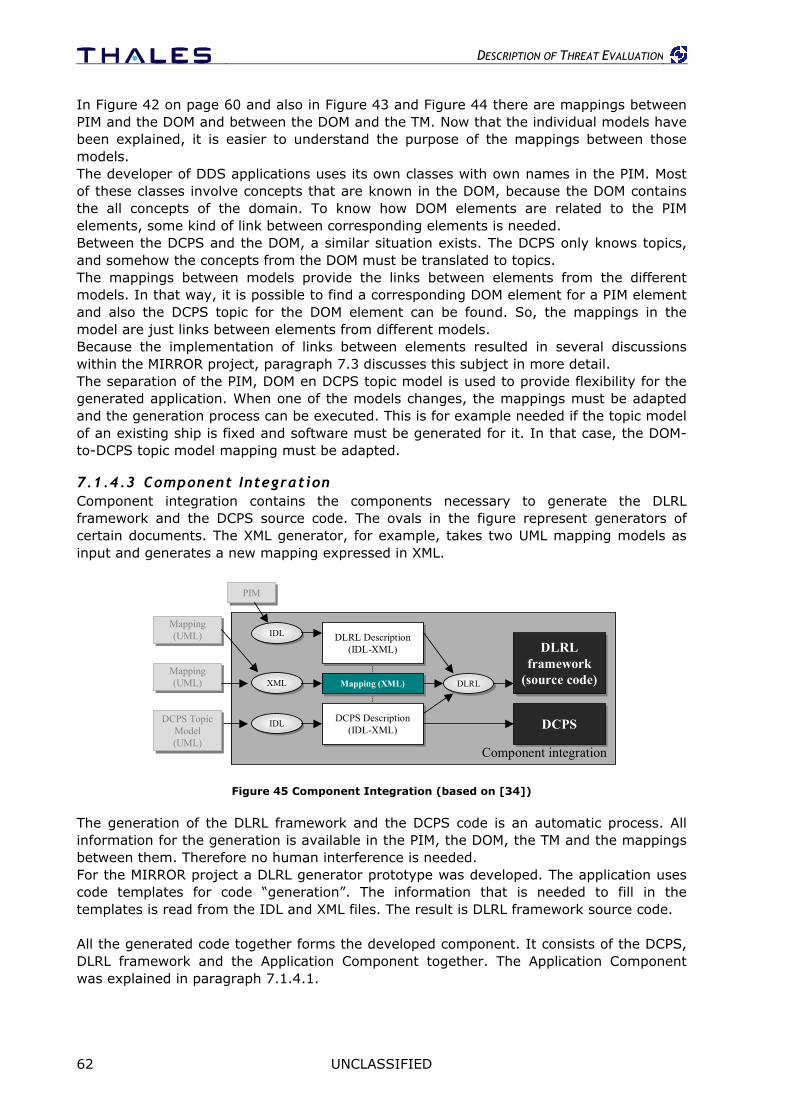
DESCRIPTION OF THREAT EVALUATION
In Figure 42 on page 60 and also in Figure 43 and Figure 44 there are mappings between PIM and the DOM and between the DOM and the TM. Now that the individual models have been explained, it is easier to understand the purpose of the mappings between those models. The developer of DDS applications uses its own classes with own names in the PIM. Most of these classes involve concepts that are known in the DOM, because the DOM contains the all concepts of the domain. To know how DOM elements are related to the PIM elements, some kind of link between corresponding elements is needed. Between the DCPS and the DOM, a similar situation exists. The DCPS only knows topics, and somehow the concepts from the DOM must be translated to topics. The mappings between models provide the links between elements from the different models. In that way, it is possible to find a corresponding DOM element for a PIM element and also the DCPS topic for the DOM element can be found. So, the mappings in the model are just links between elements from different models. Because the implementation of links between elements resulted in several discussions within the MIRROR project, paragraph 7.3 discusses this subject in more detail. The separation of the PIM, DOM en DCPS topic model is used to provide flexibility for the generated application. When one of the models changes, the mappings must be adapted and the generation process can be executed. This is for example needed if the topic model of an existing ship is fixed and software must be generated for it. In that case, the DOM-to-DCPS topic model mapping must be adapted.
7.1.4.3 Component Integration Component integration contains the components necessary to generate the DLRL framework and the DCPS source code. The ovals in the figure represent generators of certain documents. The XML generator, for example, takes two UML mapping models as input and generates a new mapping expressed in XML.
DLRL Description (IDL-XML)
DLRL Description (IDL-XML)
DCPS Description (IDL-XML)
DCPS Description (IDL-XML)
DLRLDLRLXMLXML
IDLIDL
Mapping (XML)Mapping (XML)
IDLIDL
DLRL framework
(source code)
DLRL framework
(source code)
DCPSDCPS
Component integration
PIMPIM
Mapping(UML)
Mapping(UML)
Mapping(UML)
Mapping(UML)
DCPS Topic Model(UML)
DCPS Topic Model(UML)
Figure 45 Component Integration (based on [34])
The generation of the DLRL framework and the DCPS code is an automatic process. All information for the generation is available in the PIM, the DOM, the TM and the mappings between them. Therefore no human interference is needed. For the MIRROR project a DLRL generator prototype was developed. The application uses code templates for code “generation”. The information that is needed to fill in the templates is read from the IDL and XML files. The result is DLRL framework source code. All the generated code together forms the developed component. It consists of the DCPS, DLRL framework and the Application Component together. The Application Component was explained in paragraph 7.1.4.1.
UNCLASSIFIED 62

DESCRIPTION OF THREAT EVALUATION
7.1.5 Another v iew of the b ig p icture Besides the schematic overview of the processes, a more graphical picture was created by MIRROR [34]. The picture distinguishes between automatic processes and user interaction by using different icons for them. The human interaction is depicted by image of a person working with a computer. Gearwheels indicate the automatic processes. Figure 46 contains the complete picture with all the processes and artefacts in it. In addition to the schematic representation this picture shows some more details of involved subprocesses. This paragraph contains an explanation of the extra elements that are not in Figure 42, the DCPS–DLRL Schematic Overview.
UML Topic Static model
UML DOM Static model
UML PIM Static model
Mapping GUI
UML PIM - DOM Mapping model
UML DOM - Topic Mapping model
UML PIM-Topic Mapping model
PIM - IDL Transform.
Topic - IDL Transform.
PIM - PSM Transform.
Topic IDL
PIM IDL
Mapping XML
UML mapping -XML Transform .
DLRL Generator
C++
C++
C++ DLRL Core
Application specific DLRL classes
Application specific implementation classes
DLRL Core
UML PIM Dynamic model
Code Generator
Dynamic model
Create PSM interaction diagrams
Add application logic to the PSM
mapping plugin
Application executable
Appl. Specific DLRL Classes
Appl. Specific Classes
<<provided>>
UML PSM Model
Mapping GUI
<<read -only>>
<<read -only>>
<<provided>>
DDS_DLRL IDL
<<provided>>
<<generated>>
Figure 46 DCPS-DLRL Graphic Overview (taken from [34])
The UML PIM-DOM and DOM-Topic Mapping Models still contain the mapping between the input models. Every mapping model now also has a mapping GUI. This means that the mapping between the models is realized using a custom tailored interface specialized in creating mappings between models. This will be explained in more detail in paragraph 7.3. Another difference between this figure and Figure 42 is that the UML PIM dynamic model is used separate from the static model. The static model is transformed automatically, while the dynamic model is transformed by hand. This means that the dynamic behavior that was specified for the PIM must be translated to the PSM by hand. Furthermore, user interaction is needed to complete the PSM for code generation. The PIM-to-PSM transformation only transforms the static model and therefore, only the static model for the PSM can be generated. The user has to add dynamic models and the corresponding code that must be executed.
UNCLASSIFIED 63

DESCRIPTION OF THREAT EVALUATION
The picture presented in this paragraph contains some more elements than the schematic picture. However, the layout and the pictograms help to clarify the involved processes. Figure 42 and Figure 46 together form a rather complete explanation of the DDS generation process used in MIRROR.
7 .2 MDA and M IRROR Within the MIRROR project, transformations are used to generate or derive artifacts from other artifacts. In this way abstract high-level designs can be transformed into executable applications. The MDA guide [33] has a complete chapter dedicated to MDA transformations. In this paragraph, the similarities and differences between the MDA vision and MIRRORs MDA vision are described.
7.2.1 Transformat ions in MDA Figure 47 shows the way a transformation is represented in MDA. Such a transformation is called a pattern. In paragraph 3.1.8, four different MDA patterns were described: Manual transformations, Profiles, Patterns and Markings and Automatic transformations.
Figure 47 MDA pattern (taken from [33])
In the MIRROR project a combination of patterns is used. MIRROR uses a combination of profiles, patterns and markings and automated transformations. The PIM is marked using stereotypes, defined in the PIM profile. The markings indicate which classes are shared or distributed. Transformations are executed automatic based on these markings. Several PIMs could be transformed using the same transformation.
7.2.2 Alternat ive v iew of Transformat ions in M IRROR A large set of different transformations is used in MIRROR. The complete picture contains seven different processes that could be interpreted as transformations. In this context, the word “transformation” is used for any process that creates artifacts, based on other artifacts. The input for a transformation can also be extra information. This extra information can be input from the user to direct the transformation. Also platform models and transformation specifications can be used as extra input for a transformation. In most cases a set of transformations can be seen as one big black-box transformation that is composed of smaller ones (see paragraph 4.4.9 Composition capability). In that case the image abstracts away from the transformation details. Using this approach to reduce Figure 42 to one process did not result in a desirable picture. The highest level of abstraction that can be shown for the MIRROR transformation is one that executes the transformation in two steps. The steps cannot be seen as one step, because the information that is added in the second transformation is dependent on the generated PSM models in the first transformation step. When the typical MDA pattern image [33] is used for the MIRROR project the following picture emerges.
UNCLASSIFIED 64

DESCRIPTION OF THREAT EVALUATION
PSM BehaviorModel
DDSApplication
PIM, DOM,TOPIC
mappings
Figure 48 Top-level View of Transformation in MIRROR
The resulting picture is oversimplified and does not provide information about the processes involved. Also the picture does not give a correct representation of the way the transformations are executed. Some artifacts can be created directly from the source and don’t need behavioral models. To solve this problem the typical MDA pattern should be applied a third time in a slightly adapted way. The following picture is based on Figure 42, with the extra pattern. It is rotated ninety degrees to the right, so that the top part represents the input and the bottom part the output. Furthermore several transformations are joined to one big transformation. This leads to fewer elements in the picture, which makes it easier to comprehend. The added transformation shows the transformation with the PIM, the PIM-DOM mapping model, the DOM-TM mapping model en the TM as input and the DLRL framework as output.
PIMPIM DOMDOM TMTMPIM-DOMMapping
model
PIM-DOMMapping
model
DOM-TMMapping
model
DOM-TMMapping
model
PSMPSM
Applicationcode
Applicationcode
BehaviorModel
BehaviorModel
DLRLDLRL DCPSDCPS
Figure 49 Alternative Transformation Overview
UNCLASSIFIED 65
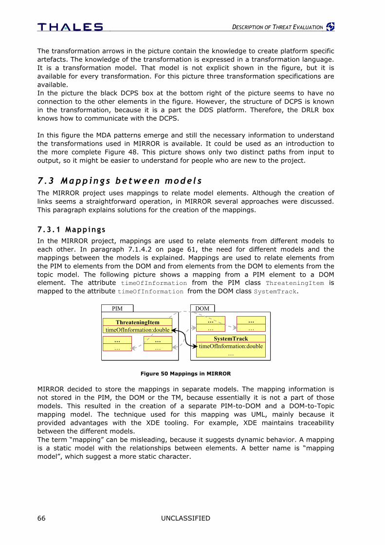
DESCRIPTION OF THREAT EVALUATION
The transformation arrows in the picture contain the knowledge to create platform specific artefacts. The knowledge of the transformation is expressed in a transformation language. It is a transformation model. That model is not explicit shown in the figure, but it is available for every transformation. For this picture three transformation specifications are available. In the picture the black DCPS box at the bottom right of the picture seems to have no connection to the other elements in the figure. However, the structure of DCPS is known in the transformation, because it is a part the DDS platform. Therefore, the DRLR box knows how to communicate with the DCPS. In this figure the MDA patterns emerge and still the necessary information to understand the transformations used in MIRROR is available. It could be used as an introduction to the more complete Figure 48. This picture shows only two distinct paths from input to output, so it might be easier to understand for people who are new to the project.
7 .3 Mapp ings be tween mode l s The MIRROR project uses mappings to relate model elements. Although the creation of links seems a straightforward operation, in MIRROR several approaches were discussed. This paragraph explains solutions for the creation of the mappings.
7.3.1 Mappings In the MIRROR project, mappings are used to relate elements from different models to each other. In paragraph 7.1.4.2 on page 61, the need for different models and the mappings between the models is explained. Mappings are used to relate elements from the PIM to elements from the DOM and from elements from the DOM to elements from the topic model. The following picture shows a mapping from a PIM element to a DOM element. The attribute timeOfInformation from the PIM class ThreateningItem is mapped to the attribute timeOfInformation from the DOM class SystemTrack.
DOMDOMPIMPIM
SystemTracktimeOfInformation:double
…
……
……
……
……
ThreateningItemtimeOfInformation:double
Figure 50 Mappings in MIRROR
MIRROR decided to store the mappings in separate models. The mapping information is not stored in the PIM, the DOM or the TM, because essentially it is not a part of those models. This resulted in the creation of a separate PIM-to-DOM and a DOM-to-Topic mapping model. The technique used for this mapping was UML, mainly because it provided advantages with the XDE tooling. For example, XDE maintains traceability between the different models. The term “mapping” can be misleading, because it suggests dynamic behavior. A mapping is a static model with the relationships between elements. A better name is “mapping model”, which suggest a more static character.
UNCLASSIFIED 66

DESCRIPTION OF THREAT EVALUATION
7.3.2 UML constructs Several UML constructs could be used to implement a mapping. One of the properties of a mapping is that it can be attached to several UML elements. This paragraph describes UML constructs that can be attached to other elements. Therefore the structure of UML is used. UML and its structure are described in paragraph 3.1.5.
7.3.2.1 Comments The Comments package contains the element Comment. Comments can be attached to a set of model elements. However, the specification states that they contain textual annotations that do not add semantics to a model. Therefore, comments cannot be used to implement mappings.
7.3.2.2 Constraints A constraint is similar to a comment, except that a constraint can contain additional semantic information. Tools may be able to verify some aspects of the constraints. The word “may” suggests that the evaluation of UML constraints is not standardized. In fact, the evaluation of OCL is explicitly said to be tool-dependant [43]. Another disadvantage of constraints is that a constraint is attached to one set of elements. No distinction is made between source and target elements. So, with the right tooling, it might be possible to use constraints for mappings, but constraints were not intended for this usage.
7.3.2.3 Relationship The Relationship package contains elements that represent some kind of relation between elements. According to the requirements for MIRROR, a solution for mappings should be in this package. One of the well-known classes in the Relationship package is the Association. According to the specification, an Association declares a relationship that may occur between instances of classifiers at the association’s end. An instance of an Association is called a link [44]. Although this seems like a solution for the problem addressed in this paragraph, it doesn’t provide the capability to connect attributes to each other, because attributes are not classifiers. Therefore, association cannot be used for the mappings in MIRROR.
Figure 51 Elements in the Relationships Package (taken from [43])
UNCLASSIFIED 67
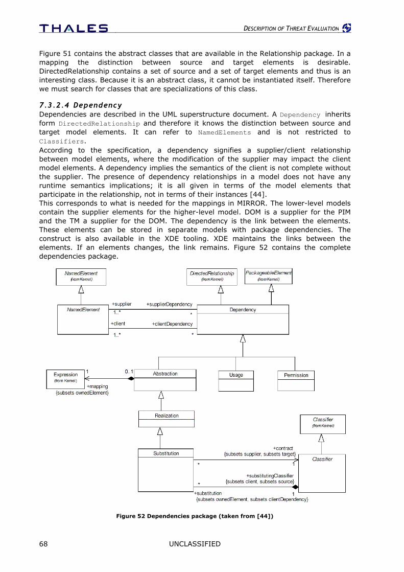
DESCRIPTION OF THREAT EVALUATION
Figure 51 contains the abstract classes that are available in the Relationship package. In a mapping the distinction between source and target elements is desirable. DirectedRelationship contains a set of source and a set of target elements and thus is an interesting class. Because it is an abstract class, it cannot be instantiated itself. Therefore we must search for classes that are specializations of this class.
7.3.2.4 Dependency Dependencies are described in the UML superstructure document. A Dependency inherits form DirectedRelationship and therefore it knows the distinction between source and target model elements. It can refer to NamedElements and is not restricted to Classifiers. According to the specification, a dependency signifies a supplier/client relationship between model elements, where the modification of the supplier may impact the client model elements. A dependency implies the semantics of the client is not complete without the supplier. The presence of dependency relationships in a model does not have any runtime semantics implications; it is all given in terms of the model elements that participate in the relationship, not in terms of their instances [44]. This corresponds to what is needed for the mappings in MIRROR. The lower-level models contain the supplier elements for the higher-level model. DOM is a supplier for the PIM and the TM a supplier for the DOM. The dependency is the link between the elements. These elements can be stored in separate models with package dependencies. The construct is also available in the XDE tooling. XDE maintains the links between the elements. If an elements changes, the link remains. Figure 52 contains the complete dependencies package.
Figure 52 Dependencies package (taken from [44])
UNCLASSIFIED 68
DESCRIPTION OF THREAT EVALUATION
7.3.2.5 Abstraction An Abstraction is a direct subclass of a Dependency. The semantics of an abstraction are slightly different from the semantics of the ordinary dependency. An abstraction relates elements that represent the same concept, but at different abstraction levels. The distinction between a PIM and a PSM is the viewpoint. The viewpoint is the level of abstraction (see paragraph 3.1.4 Viewpoints). Therefore, the difference between a PIM and a PSM is the level of abstraction. Links between PIM and PSM elements should therefore be implemented using Abstractions.
7.3.3 Conclus ion The new UML, version 2.0, does provide a means for specifying mappings between model elements. MIRROR now uses dependencies to implement mappings. Dependencies have the required semantics and are supported by the tooling, so the choice for dependencies is probably the best choice for the MIRROR project. Abstractions can be used to record links between source PIM models and target PSM models. These models can be created during model transformation and can be stored to provide traceability between the models (see paragraph 4.4.2 Traceability). Traceability is needed for incremental consistency or for conservative generation.
7 .4 Summary This chapter introduced the case study that was done for this assignment. The case study addressed one of the techniques that are involved in the software generation process in MIRROR. A complete overview of the project’s processes and artifacts was given using two pictures. Also a proposal for an easier, less detailed diagram was presented. The need for mapping models with mappings was explained and several possible UML solutions were discussed. Also, the chosen approach in MIRROR was observed. This chapter described the background of the case study. It described the complete picture of which the case study is only a part. The next chapter describes the development and implementation of the artifacts for the case study.
UNCLASSIFIED 69

DESCRIPTION OF THREAT EVALUATION
UNCLASSIFIED 70

DESIGN AND IMPLEMENTATION OF THREAT EVALUATION COMPONENT WITH TRL
8 Design and Implementation of Threat Evaluation component with TRL
This chapter describes how the case study, described in chapter 7, was analyzed, designed and implemented using TRL. Paragraph 8.1 describes the requirements for the transformation. From these requirements, a set of test cases was created in order to test implementations. The test cases are described in paragraph 8.2. To create a transformation, a design approach is needed. The design for this transformation is presented in 8.3. As the TRL language is a new language, without thorough documentation, some constructs of the language are explored and explained in paragraph 8.4. In 8.5 the implementation of the transformation is discussed. Based on the experiences gained during the development, the TRL language is evaluated in paragraph 9.2.
8 .1 Requ i rement s For this assignment a transformation is developed using TRL. The requirements in this paragraph are the requirements for the transformation that must be developed. The mini threat evaluation (TE) is used to evaluate TRL in a real-world situation. In [34] the transformations from a TE PIM to a TE PSM are described. The pictures used in this paragraph are taken from this document. The description in [34] is given in a rather informal way and this style is adopted in this paragraph. Although this paragraph does not contain a formal description of the transformation, it should be treated as the transformation Software Requirements Specification (SRS). Because the developed software will be used for evaluation purposes and not for production, the requirements are not as strict as normal requirements documents should be. The main purpose of this paragraph is to clarify the design choices that were made during the transformation design. Furthermore, it is used as the base for the development of test cases, described in paragraph 8.2.
8.1.1 Funct iona l requirements This paragraph describes what the result of a transformation from PIM to PSM should be. It describes what elements must be created in the target for specific elements in the source. Common Class Creation Every DDS based application needs a certain set of “foundation” classes and relationships between these classes. These must be created for every DDS application. So this structure is completely independent of the PIM. The five necessary classes are: ObjectHome, ObjectExtent, ListRelation, RefRelation and ObjectRoot. An ObjectHome is used to refer to all the created instances of a class used in the application. The home provides facilities to create objects of the type and to find a specific, existing instance. So, it is a kind of an advanced factory for a class [17]. An ObjectExtent is used to manage a set of instances. Extents are for example used by homes to hold the objects that were created. To be more precise, a home is composed of two extents. The concept of extents is also in the MOF specification. In that document, an extent is the complete set of M1 level instances of a class.
UNCLASSIFIED 71
DESIGN AND IMPLEMENTATION OF THREAT EVALUATION COMPONENT WITH TRL
The two relation classes are used to represent relations from the PIM in the PSM. For a 1-to-1 relation a RefRelation is be used, for a 1-to-many relation a ListRelation is one of the possible approaches. In a ListRelation the references to other objects are stored in a list. Other approaches are map relations that use a map to keep track of the references. In the mini TE case, only ListRelations are used. ObjectRoot is the root class, or the parent, of all implementation classes in an application. It is used like java’s class Object. Class Creation For every class in the PIM with the stereotype <<shared>> a set of classes is created in the PSM. A class must be marked as shared when it must be available in the system. To keep the case study simple, every class in the PIM is treated as a shared class. This is not according to the mini TE, in which a stereotype <<shared>> is used to refer to classes that are shared in the system. The names of the generated classes all start with the name of the PIM class following by a word describing the purpose of the class. If, for example, in the PIM a class c exists, the following classes must be created in the PSM: cImpl, cHome, cExtend, cRef, cList. Also an interface with name c must be created. Structure Creation The created classes must fit somehow into the existing PSM structure. Figure 54 depicts the structure that is needed for one PIM class, named Class1. This picture gives an impression on what to create for every class. However, it is not a complete picture. For example, if class Class1 inherits from class Class2, then the “Home” of Class1 is not a direct child of ObjectHome, but of the home of Class1. Therefore, Figure 54 can be misleading if it used without Figure 56. It shows the structure for one class, but it is not a complete description for the general case.
Class1
Figure 53 PIM Class (taken from [34])
Figure 54 PSM Class Structure (taken from [34])
UNCLASSIFIED 72

DESIGN AND IMPLEMENTATION OF THREAT EVALUATION COMPONENT WITH TRL
Inheritance The PIM-to-PSM transformation creates several PSM classes for one PIM class. Inheritance in the PIM results in several inheritance relationships in the PSM. The following figure shows the PSM for two classes: Class1 and Class2. Class1 extends Class2, so Class1 is the child and Class2 is the parent.
Class1
Class2
Figure 55 PIM inheritance (taken from [34])
Figure 56 PSM Inheritance (taken from [34])
There are three different ways inheritance is generated in the PSM. The first and simplest one is the generalization between the extents and ObjectExtent and between the homes and ObjectHome. All the homes and extents directly inherit from ObjectHome and ObjectExtent respectively. This inheritance is not dependent of the inheritance in the PIM. The second type of generalization is the one between the interfaces. Here the inheritance from the source PIM is copied to the PSM. If a class A is a specialization of another class B in the PIM, then the interface of A is a specialization of the interface of B in the PSM. The inheritance described for the interfaces is similar to the one used for the implementations. Also the inheritance from the PIM is copied to the PSM. Furthermore, every implementation class that has no parent in the PIM inherits directly from ObjectRoot. Classes that do not have a parent in the PIM are called root classes in the following paragraphs. Relationships In PIMs, two different kind of association are possible: Associations from one-to-one and associations from one-to-many. The following pictures show the case for one-to-one associations.
UNCLASSIFIED 73

DESIGN AND IMPLEMENTATION OF THREAT EVALUATION COMPONENT WITH TRL
Class1Class2- _Class2
1
Figure 57 PIM relation (taken from [34])
In the PSM, a relation must be implemented using a reference to the reference class of the other class. In this case the other class is Class2 and its reference class is called Class2Ref.
Class2<<interface>>
C lass1Impl Class2Impl
Class1<<int erface>>
C lass2Ref11
-Class2Ref
Figure 58 PSM Relation (taken from [34])
In order to create a one-to-many relation, the reference is not made to the reference (“Ref”) of the class, but to the list (“List”) of the class. Boundaries No elements but the elements described in this paragraph are created in the PSM. An exception is made for the elements that are needed in order to create the required elements, according to the UML specification. For example, associationEnds must be created to create an association. # Short Description 1 The transformation shall create 5 base classes 2 For every class in the source:
• Create a home, an extent, a list, a ref, a implementation and an interface o The extent is a child of ObjectExtent and the home is a child of
ObjectHome o The home has two association to the extend, named extent and
full_extent o The extent has an association to the interface, named Objects o The implementation has a implements relation to the interface
3 For every association in the source: • Create a reference to the reference class of the other object, if the
multiplicity is one • Create a reference to the list class of the other object, if the multiplicity
is many 4a For every class without a generalization in the source:
• Create a generalization from the implementation to ObjectRoot 4b For every class with a generalization in the source:
• Create a generalization from the implementation to the implementation of the generalization class
• Create a generalization from the interface to the interface of the generalization class
Table 4 Requirements Summary
UNCLASSIFIED 74
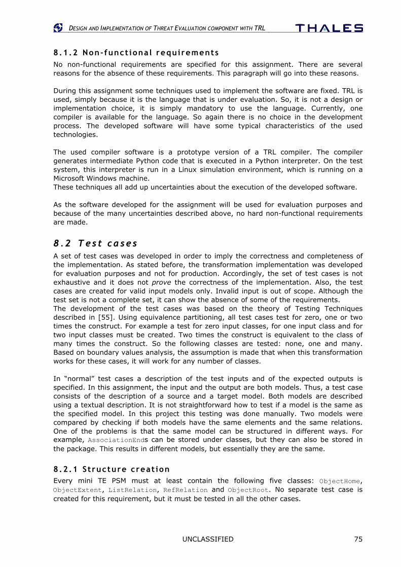
DESIGN AND IMPLEMENTATION OF THREAT EVALUATION COMPONENT WITH TRL
8.1.2 Non-funct iona l requirements No non-functional requirements are specified for this assignment. There are several reasons for the absence of these requirements. This paragraph will go into these reasons. During this assignment some techniques used to implement the software are fixed. TRL is used, simply because it is the language that is under evaluation. So, it is not a design or implementation choice, it is simply mandatory to use the language. Currently, one compiler is available for the language. So again there is no choice in the development process. The developed software will have some typical characteristics of the used technologies. The used compiler software is a prototype version of a TRL compiler. The compiler generates intermediate Python code that is executed in a Python interpreter. On the test system, this interpreter is run in a Linux simulation environment, which is running on a Microsoft Windows machine. These techniques all add up uncertainties about the execution of the developed software. As the software developed for the assignment will be used for evaluation purposes and because of the many uncertainties described above, no hard non-functional requirements are made.
8 .2 Test case s A set of test cases was developed in order to imply the correctness and completeness of the implementation. As stated before, the transformation implementation was developed for evaluation purposes and not for production. Accordingly, the set of test cases is not exhaustive and it does not prove the correctness of the implementation. Also, the test cases are created for valid input models only. Invalid input is out of scope. Although the test set is not a complete set, it can show the absence of some of the requirements. The development of the test cases was based on the theory of Testing Techniques described in [55]. Using equivalence partitioning, all test cases test for zero, one or two times the construct. For example a test for zero input classes, for one input class and for two input classes must be created. Two times the construct is equivalent to the class of many times the construct. So the following classes are tested: none, one and many. Based on boundary values analysis, the assumption is made that when this transformation works for these cases, it will work for any number of classes. In “normal” test cases a description of the test inputs and of the expected outputs is specified. In this assignment, the input and the output are both models. Thus, a test case consists of the description of a source and a target model. Both models are described using a textual description. It is not straightforward how to test if a model is the same as the specified model. In this project this testing was done manually. Two models were compared by checking if both models have the same elements and the same relations. One of the problems is that the same model can be structured in different ways. For example, AssociationEnds can be stored under classes, but they can also be stored in the package. This results in different models, but essentially they are the same.
8.2.1 Structure creat ion Every mini TE PSM must at least contain the following five classes: ObjectHome, ObjectExtent, ListRelation, RefRelation and ObjectRoot. No separate test case is created for this requirement, but it must be tested in all the other cases.
UNCLASSIFIED 75

DESIGN AND IMPLEMENTATION OF THREAT EVALUATION COMPONENT WITH TRL
8.2.2 PIM spec i f ic c lasses Every element in the PIM results in a set of classes and relation in the PSM. The names of the created classes depend on the name of the PIM class. For one PIM class the following elements must be created:
• An interface with the same name as the PIM class • A Class with the same name, followed by “Extent” • A Class with the same name, followed by “Home” • A Class with the same name, followed by “List” • A Class with the same name, followed by “Ref” • A Class with the same name, followed by “Impl”
In the following paragraphs, the interface, the extent, the home, the list, the reference and the implementation will be used to refer to these elements respectively. Some of the generalizations that must be created are dependent on the generalizations that are in the PIM model. The following generalizations must be created:
• Implementation o From the implementation to ObjectRoot, if the PIM class has no parents o From the implementation to the implementation of the parent class in the
PIM, otherwise • From the “Extent” to ObjectExtent • From the “Home” to ObjectHome • From the “List” to ListRelation • From the “Ref” to RefRelation
Three associations are created for every PIM class.
• An association from the Home to the Extent with the name extent • An association from the Home to the Extent with the name extent • An association from the Extent to the Interface
Finally, one implementation or realization association is created from the Implementation to the Interface. The test cases are described using the following table structure. Test case number – test case name PIM description, describes the structure that is the required input for the test case.
PSM description, describes the required output.
Table 5 Test Case General Structure
In order to test this, the following test cases are executed. 1.1 – One input class One class named Class1 The resulting model must be as described above. The
resulting picture should resemble Figure 54 on page 72, depending on the used modeling tool.
1.2 – Two input classes Two classes named Class1 and Class2
Attention must be paid to the generalizations that are made to the base classes; they must be present for both classes.
UNCLASSIFIED 76

DESIGN AND IMPLEMENTATION OF THREAT EVALUATION COMPONENT WITH TRL
1.3 – Zero input classes No classes in the PIM Only the “foundation” classes should be created.
Table 6 PIM specific classes Test Cases
8.2.3 Assoc iat ion One association in the PIM results in one association in the PSM. If the association in the PIM points from class left to a class right, then the association in the PSM is between left’s interface and the “Relation” or the “List” class of right. It points to the “Relation”, if the multiplicity of the association in the PIM is equal to 1. It points to the “List” if the multiplicity is many (*). The other side of the association in the PIM is assumed to always have multiplicity of 1. 2.1 – To-one Association Two classes named Class1 and Class2 with one association from Class1 to Class2 with multiplicity of 1
The same structure as in 1.2, but with an extra association from interface Class1 to the class Class2Ref.
2.2 – To-many Association Two classes named Class1 and Class2 with one association from Class1 to Class2 with multiplicity of *
The same as 1.2, but with an extra association from interface Class1 to the class Class2List.
2.3 – To-one Association with order Four classes Class1, Class2, Class3 and Class4 with an association from Class1 to Class2 and one from Class4 to Class3 both with multiplicity of 1
The same as 1.2 But now 2 references should be created instead of one. One from the interface Class1 to the class Class2Ref and one from the interface of Class4 to the class Class3Ref.
2.4 – To-many Association with order Four classes Class1, Class2, Class3 and Class4 with an association from Class1 to Class2 and one from Class4 to Class3 both with multiplicity of 1
The same as 1.2 But now 2 references should be created instead of one. One from the interface Class1 to the class Class2List and one from the interface of Class4 to the class Class3List.
Table 7 Association Test Cases
It is assumed that the addition of extra relations does not add complexity to the transformation. Therefore, the test case set is limited to this number of cases.
8.2.4 Genera l izat ion Generalization is far more complicated than the other subjects. Because the PSM elements for a PIM class with no parent are different from a PIM class with a parent, the test cases are developed to test for both cases.
UNCLASSIFIED 77
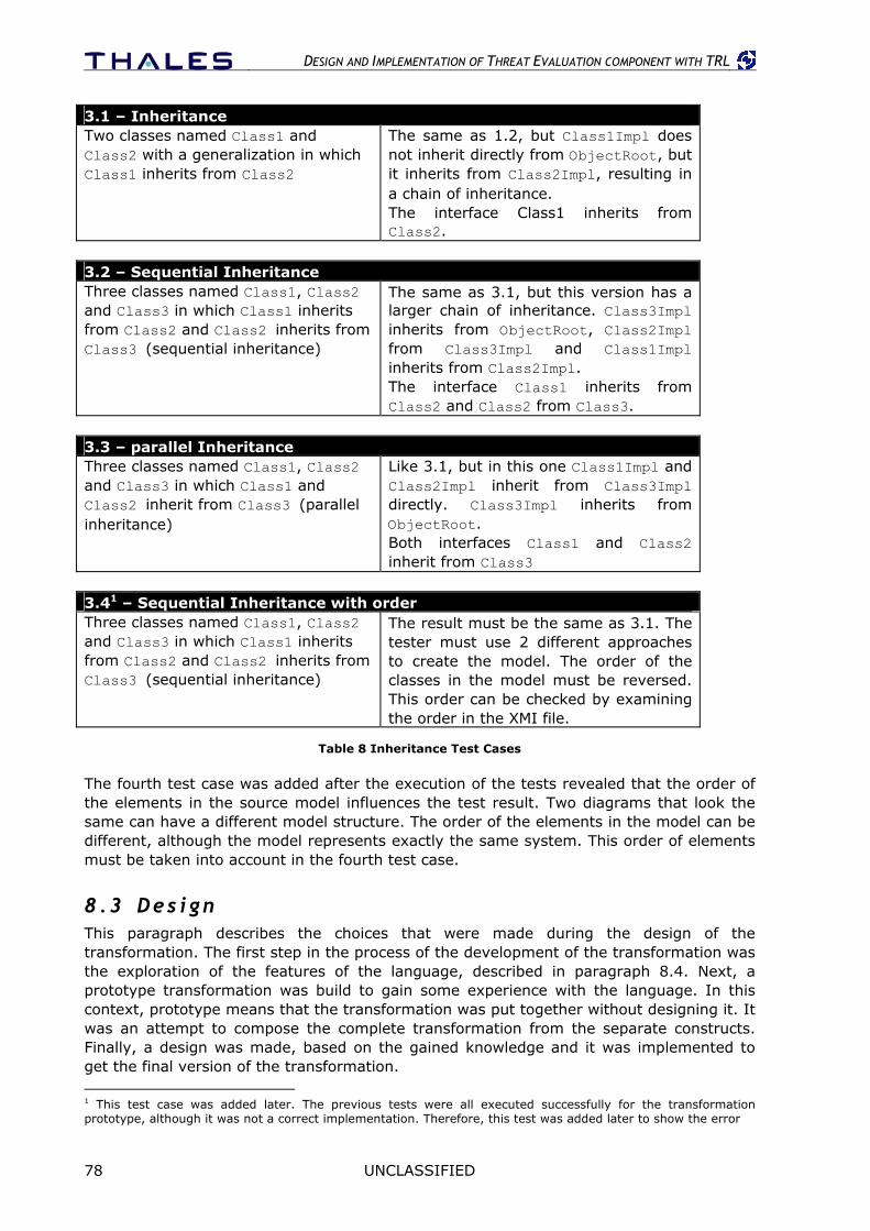
DESIGN AND IMPLEMENTATION OF THREAT EVALUATION COMPONENT WITH TRL
3.1 – Inheritance Two classes named Class1 and Class2 with a generalization in which Class1 inherits from Class2
The same as 1.2, but Class1Impl does not inherit directly from ObjectRoot, but it inherits from Class2Impl, resulting in a chain of inheritance. The interface Class1 inherits from Class2.
3.2 – Sequential Inheritance Three classes named Class1, Class2 and Class3 in which Class1 inherits from Class2 and Class2 inherits from Class3 (sequential inheritance)
The same as 3.1, but this version has a larger chain of inheritance. Class3Impl inherits from ObjectRoot, Class2Impl from Class3Impl and Class1Impl inherits from Class2Impl. The interface Class1 inherits from Class2 and Class2 from Class3.
3.3 – parallel Inheritance Three classes named Class1, Class2 and Class3 in which Class1 and Class2 inherit from Class3 (parallel inheritance)
Like 3.1, but in this one Class1Impl and Class2Impl inherit from Class3Impl directly. Class3Impl inherits from ObjectRoot. Both interfaces Class1 and Class2 inherit from Class3
3.41 – Sequential Inheritance with order Three classes named Class1, Class2 and Class3 in which Class1 inherits from Class2 and Class2 inherits from Class3 (sequential inheritance)
The result must be the same as 3.1. The tester must use 2 different approaches to create the model. The order of the classes in the model must be reversed. This order can be checked by examining the order in the XMI file.
Table 8 Inheritance Test Cases
The fourth test case was added after the execution of the tests revealed that the order of the elements in the source model influences the test result. Two diagrams that look the same can have a different model structure. The order of the elements in the model can be different, although the model represents exactly the same system. This order of elements must be taken into account in the fourth test case.
8 .3 Des ign This paragraph describes the choices that were made during the design of the transformation. The first step in the process of the development of the transformation was the exploration of the features of the language, described in paragraph 8.4. Next, a prototype transformation was build to gain some experience with the language. In this context, prototype means that the transformation was put together without designing it. It was an attempt to compose the complete transformation from the separate constructs. Finally, a design was made, based on the gained knowledge and it was implemented to get the final version of the transformation.
1 This test case was added later. The previous tests were all executed successfully for the transformation prototype, although it was not a correct implementation. Therefore, this test was added later to show the error
UNCLASSIFIED 78
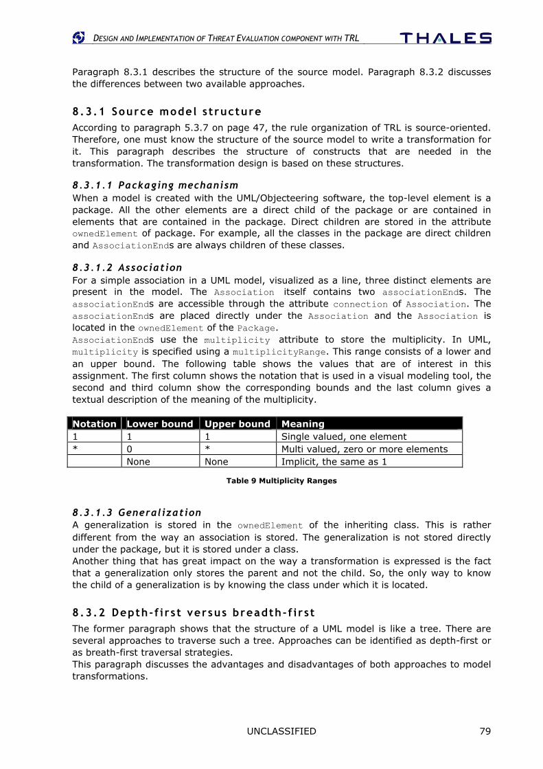
DESIGN AND IMPLEMENTATION OF THREAT EVALUATION COMPONENT WITH TRL
Paragraph 8.3.1 describes the structure of the source model. Paragraph 8.3.2 discusses the differences between two available approaches.
8.3.1 Source model s t ructure According to paragraph 5.3.7 on page 47, the rule organization of TRL is source-oriented. Therefore, one must know the structure of the source model to write a transformation for it. This paragraph describes the structure of constructs that are needed in the transformation. The transformation design is based on these structures.
8.3.1.1 Packaging mechanism When a model is created with the UML/Objecteering software, the top-level element is a package. All the other elements are a direct child of the package or are contained in elements that are contained in the package. Direct children are stored in the attribute ownedElement of package. For example, all the classes in the package are direct children and AssociationEnds are always children of these classes.
8.3.1.2 Association For a simple association in a UML model, visualized as a line, three distinct elements are present in the model. The Association itself contains two associationEnds. The associationEnds are accessible through the attribute connection of Association. The associationEnds are placed directly under the Association and the Association is located in the ownedElement of the Package. AssociationEnds use the multiplicity attribute to store the multiplicity. In UML, multiplicity is specified using a multiplicityRange. This range consists of a lower and an upper bound. The following table shows the values that are of interest in this assignment. The first column shows the notation that is used in a visual modeling tool, the second and third column show the corresponding bounds and the last column gives a textual description of the meaning of the multiplicity. Notation Lower bound Upper bound Meaning 1 1 1 Single valued, one element * 0 * Multi valued, zero or more elements None None Implicit, the same as 1
Table 9 Multiplicity Ranges
8.3.1.3 Generalization A generalization is stored in the ownedElement of the inheriting class. This is rather different from the way an association is stored. The generalization is not stored directly under the package, but it is stored under a class. Another thing that has great impact on the way a transformation is expressed is the fact that a generalization only stores the parent and not the child. So, the only way to know the child of a generalization is by knowing the class under which it is located.
8.3.2 Depth- f i r s t versus breadth- f i r s t The former paragraph shows that the structure of a UML model is like a tree. There are several approaches to traverse such a tree. Approaches can be identified as depth-first or as breath-first traversal strategies. This paragraph discusses the advantages and disadvantages of both approaches to model transformations.
UNCLASSIFIED 79

DESIGN AND IMPLEMENTATION OF THREAT EVALUATION COMPONENT WITH TRL
According to its name, the depth-first approach will traverse the tree in a way in which the deepest elements are traversed first. In order to demonstrate this technique, an example is presented showing the way generalization is stored. Figure 59 shows two representations of a model with inheritance. The example consists of a package p, with two classes ClassA and ClassB. ClassB is a child of ClassA. The left picture shows the typical representation as it is used in a modeling tool. The picture on the right shows the representation of that same model in the model repository, as it might be stored.
p:Packagep:Package
ClassA:ClassClassA:Class
ClassB:ClassClassB:Class
g:Generalizationg:Generalizationparent:Referenceparent:Reference
ownedElementownedElement
ownedElementownedElementClassAClassA
ClassBClassB
p
Figure 59 Tree traversal example
The depth first approach would start with the top-level element p. Then it would go to ClassB and then to g. As g is the deepest element of the branch, the traversal will backtrack to the next branch. In this case, it will go to ClassA and then the traversal is complete. The depth-first approach uses the typical constructs of TRL. In TRL rules call other rules. Obviously, a first attempt to write a TRL program uses this approach. First a rule for the package is created. In that rule a call is made to the class rule. In the class rule a call is made to the generalization rule. Although this approach corresponds to the structure of TRL, there are some drawbacks that occur using this technique. When the generalization g is reached in the example, ClassA was not encountered yet. Therefore a link to this element cannot be created. Using the prototype of the TRL compiler, this problem is only encountered at run-time and is therefore hard to recognize. The problem that was described here is difficult to tackle. It even might be impossible to get the code working for every model using this approach. The breadth-first approach will not go deep into the tree, but traverses first all the elements on a certain level. This approach in TRL results in a number of traversals through the model tree. The word phase is used for such a traversal. For example, the first phase will generate all the classes. So, the according rule will get all the classes from the source package. Then in a next phase all generalizations must be fetched. Again all classes must be traversed, because the generalization is nested within these classes (see 8.3.1.3). Although the multiple traversals result in a slightly worse performance for the transformation, it is straightforward to prove that the transformation will always generate the correct PSM. This proof will be given in the following paragraph. Such a proof for the depth-first approach will at least be very difficult, if it exists. The breath-first approach is chosen for the final version of the transformation. This results in a larger transformation, but it is easier to show that the transformation can execute for every model.
UNCLASSIFIED 80
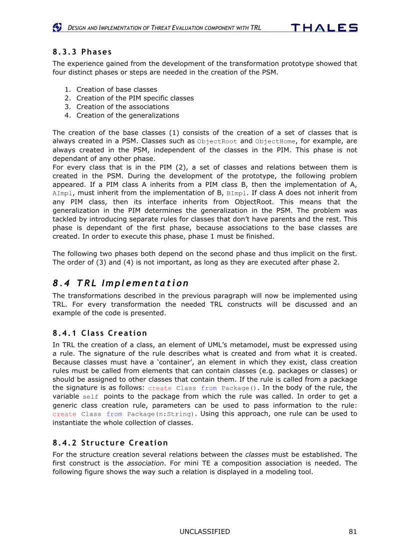
DESIGN AND IMPLEMENTATION OF THREAT EVALUATION COMPONENT WITH TRL
8.3.3 Phases The experience gained from the development of the transformation prototype showed that four distinct phases or steps are needed in the creation of the PSM.
1. Creation of base classes 2. Creation of the PIM specific classes 3. Creation of the associations 4. Creation of the generalizations
The creation of the base classes (1) consists of the creation of a set of classes that is always created in a PSM. Classes such as ObjectRoot and ObjectHome, for example, are always created in the PSM, independent of the classes in the PIM. This phase is not dependant of any other phase. For every class that is in the PIM (2), a set of classes and relations between them is created in the PSM. During the development of the prototype, the following problem appeared. If a PIM class A inherits from a PIM class B, then the implementation of A, AImpl, must inherit from the implementation of B, BImpl. If class A does not inherit from any PIM class, then its interface inherits from ObjectRoot. This means that the generalization in the PIM determines the generalization in the PSM. The problem was tackled by introducing separate rules for classes that don’t have parents and the rest. This phase is dependant of the first phase, because associations to the base classes are created. In order to execute this phase, phase 1 must be finished. The following two phases both depend on the second phase and thus implicit on the first. The order of (3) and (4) is not important, as long as they are executed after phase 2.
8 .4 TRL Imp lementat ion The transformations described in the previous paragraph will now be implemented using TRL. For every transformation the needed TRL constructs will be discussed and an example of the code is presented.
8.4.1 Class Creat ion In TRL the creation of a class, an element of UML’s metamodel, must be expressed using a rule. The signature of the rule describes what is created and from what it is created. Because classes must have a ‘container’, an element in which they exist, class creation rules must be called from elements that can contain classes (e.g. packages or classes) or should be assigned to other classes that contain them. If the rule is called from a package the signature is as follows: create Class from Package(). In the body of the rule, the variable self points to the package from which the rule was called. In order to get a generic class creation rule, parameters can be used to pass information to the rule: create Class from Package(n:String). Using this approach, one rule can be used to instantiate the whole collection of classes.
8.4.2 Structure Creat ion For the structure creation several relations between the classes must be established. The first construct is the association. For mini TE a composition association is needed. The following figure shows the way such a relation is displayed in a modeling tool.
UNCLASSIFIED 81

DESIGN AND IMPLEMENTATION OF THREAT EVALUATION COMPONENT WITH TRL
ClassA ClassB
aroleA roleB
1 1
Figure 60 Binary Composition Association
ClassA is composed of one ClassB. The name of the Association is a, the names of the roles are RoleA and RoleB. According to the UML 1.3 specification, there is always one root element in a model. In this case this is the package that contains the elements. Packages have an attribute called ownedElement, which contains elements that are owned by the package. In the example, ClassA, ClassB and the association a are owned by the package. The connection between the association and the classes is done via AssociationEnds. Association has an attribute connection, which contains two or more AssociationEnds. In the example exactly two AssociationEnds are needed. Every AssociationEnd contains a link to the element it refers to. Vice versa, the classes contain links to the AssociationEnds that point to them. The resulting structure for the diagram of Figure 60 is illustrated in the following tree.
p:Packagep:Package
ClassA:ClassClassA:ClassClassB:ClassClassB:Classa:Associationa:Association
roleA:AssociationEndroleA:AssociationEndroleB:AssociationEndroleB:AssociationEnd
connectionconnection
ownedElementownedElement
Figure 61 Association Element Structure
To create this structure using TRL, the following rule signatures are needed.
create Class from Package() create Association from Package() create AssociationEnd from Association()
Code fragment 5 Association Creation Signatures
The order of the rules must be from the root element towards the children. Due to the organization of rules in TRL, the tree is composed depth first. Thus, the order of creation in the example will be: package, classes, association and finally associationEnds. As described in paragraph 8.3 Design, the depth-first approach is very difficult to implement. Therefore a breath-first approach is used in the final version of the transformation. Transformation languages should have the ability to refer to elements that do not yet exist and to elements that were created in earlier executed rules. For example, the classes should contain links to the associationEnds, but at the time of the creation of the classes, the associationEnds do not exist yet. Similarly, the AssociationEnds should contain links to the classes that were created in a different rule. The following code shows the example using local variables to keep track of the generated classes.
UNCLASSIFIED 82

DESIGN AND IMPLEMENTATION OF THREAT EVALUATION COMPONENT WITH TRL
transformation ClassDiagramRefactoring; use modeltype UML; purpose create destModel:UML from srcModel:UML; activator go() { srcModel.objects()[Package]->create Package(); } rule create Package from Package() { name := "result"; var class1 := self.create Class("Class1"); var class2 := self.create Class("Class2"); self.create Association(class1, class2, "a"); ownedElement := { class1; class2; }; } -- Create package with given name rule create Class from Package(n:String) {name := n;} --Creates association 'from' c1 to c2, c1 gets diamond, c2 an arrow rule create Association from Package (c1:Class, c2:Class, n:String) { name := n; connection := { self.create AssociationEnd (c1, true, "none"); self.create AssociationEnd (c2, false, "composite"); }; } rule create AssociationEnd from Association (c:Class, navigable:boolean, aggr:String) { name := "role" + c.name; isNavigable := if navigable then "true" else "false" endif; aggregation := if aggr="aggregate" then "aggregate" else if aggr="composite" then "composite" endif endif; type:=c; }
Code fragment 6 Local Variable Usage
In the example the variables class1 and class2 are used to hold the created elements. These references are passed to the association rule and later are passed again to the associationEnd rules. Another interesting part is the usage of the if-then-else statement or expression. The structure can only be used in an assignment and not as a standalone statement. It is also not present in the TRL grammar listed on page XXV, in the end of the document. As expressions are not treated in the grammar the if-then-else structure is probable seen as an expression. In order to use a composition aggregation the multiplicity of the associationEnd must be specified. The code illustrates the creation of an associationEnd with multiplicityRange {0..1} and one with {0..*}. rule create Association from Package(c1:Class, c2:Class) { connection := { self.create "diamond" AssociationEnd (c1); self.create "arrow" AssociationEnd (c2); }; } rule create "diamond" AssociationEnd from Association(c:Class){ aggregation := "composite"; multiplicity := "{'range': {'upper': '1', 'lower': '0'}}"; isNavigable := "false"; type := c; } rule create "arrow" AssociationEnd from Association (c:Class) { aggregation := "none"; multiplicity := "{'range': {'upper': '*', 'lower': '0'}}"; isNavigable := "true"; type := c; }
Code fragment 7 MultiplicityRanges
UNCLASSIFIED 83
DESIGN AND IMPLEMENTATION OF THREAT EVALUATION COMPONENT WITH TRL
This way of creating multiplicityRanges is not according to the UML standard, but it uses the textual notation that Univers@lis uses to represent multiplicityRanges.
8.4.3 Stereotypes In UML, classes can be stereotyped. Within a package, a stereotype is stored at the same level of the classes in the package. To indicate that a certain class has a stereotype, a link to the stereotype is stored in the stereotype. A link to the stereotype is also stored in the attribute stereotype of the class. The following code generates a stereotyped class in a package. rule create Package from Package() { var c := self.create Class("class1"); ownedElement := { c; self.create "shared" Stereotype(c); }; } rule create "shared" Stereotype from Package(c:Class) { name := "shared"; baseClass := "Class"; icon := ""; extendedElement := c; } rule create Class from Package(n:String) {name := n;}
Code fragment 8 Stereotypes
According to the code, the relation between the class and the stereotype is only stored in the stereotype (extensionElement:=c;) and not in the class. However, the execution of this code results not only in the creation of the link from the stereotype to the class, but also the link from the class to the stereotype is created. Thus, an implicit mechanism creates extra links to complete the model.
8.4.4 Implement ing an Interface This paragraph describes the structure that is needed for an interface, a class and an “implements” relation between the class and the interface. The meaning of this in UML is that the class is an implementation of the interface. The needed structure is rather complex, which is shown in the following code fragment. rule create Package from Package() { var i = self.create Interface(); var s = self.create "realize" Stereotype(); var a = self.create Abstraction(s, i); var c = self.create Class("ClassA"); c.clientDependency := a; ownedElement := { c; i; s; a; }; } rule create Interface from Package() { name := "myInterface"; } rule create Class from Package(n:String) { name := n; } rule create Abstraction from Package(s:Stereotype, i:Interface) { stereotype := s; supplier := i; }
UNCLASSIFIED 84
DESIGN AND IMPLEMENTATION OF THREAT EVALUATION COMPONENT WITH TRL
rule create "realize" Stereotype from Package() { baseClass := "Classifier"; icon := "realize"; name := "realize"; }
Code fragment 9 Implementation of an Interface
The realize relation is implemented using an abstraction. In UML, an abstraction is a kind of relationship between two elements that represent the same concept, but at different abstraction levels. A stereotype is used to indicate what kind of abstraction is used. <<derive>>, <<refine>> and <<trace>> are examples of predefined stereotypes. In this example, a <<realize>> stereotype is created for the realization relation. The stereotype also provides information for the modelling tool about the representation of the object. In this case, the icon realize is used to visualize the realization.
8.4.5 Inher i tance Inheritance is implemented in a straightforward way. A generalization has a child and a parent. In the parent a link to the generalization is stored in the attribute specialization. In the child it is stored under the attribute generalization. rule create Package from Package() { var p := self.create Class("Parent"); var c := self.create Class("Child"); var g := self.create Generalization(p,c); ownedElement := { c; p; g; }; } rule create Class from Package(n:String) { name := n; } rule create Generalization from Package(c:Class) { parent:=p; child:=c; }
Code fragment 10 Generalization
Again, this code does not describe the creation of the link from the child and the parent to the generalization. These links are created implicitly.
8 .5 Imp lementat ion In this section, the order of the dynamic behavior in the implementation is visualized in an activity diagram. Also, the execution of the test cases for the result of the implementation is presented. An explanation of a design error that appeared during implementation is shown. And finally the execution time of the resulted software is measured.
8.5.1 Act iv i ty D iagram To visualize the dynamic behavior of the transformation, an activity diagram for the process is presented. Five distinct activity states are shown in the picture. The states correspond to the phases that are in the code of Appendix E: phase 1, 2, 3, 4a and 4b. The branches in the diagram represent the loops that are implicit in the code. In the transformation, a certain action is done for every class in the PIM. This is represented by a branch with one [processed all input Classes] and one [not process all Classes] transition as output.
UNCLASSIFIED 85

DESIGN AND IMPLEMENTATION OF THREAT EVALUATION COMPONENT WITH TRL
[not process allinput Classes][processed all
input Classes]
[not process allinput Associations]
[processed allinput Associations]
[processed all inputGeneralizations]
[not process all inputGeneralizations]
[root]
[nonroot]
Create root specificGeneralization
Create root specificGeneralization
Create nonrootSpecific Generalization
Create nonrootSpecific Generalization
Create AssociationsCreate Associations
Create PIMspecific classes
Create PIMspecific classes
Create base classesCreate base classes
Phase 1
Phase 2
Phase 3
Phase 4a
Phase 4b
Figure 62 Activity Diagram
In the final implementation the last part of the picture is slightly different from this picture. In the picture all Generalizations are processed and for every Generalization is checked if it is a root or a non-root specialization. A generalization is a root generalization if the parent has no parent, thus if the parent Class is a root. In the implementation first all root generalizations are processed and than all non-root generalizations.
8.5.2 Test cases The testing of the prototype transformation revealed that the order of elements in the model does influence the results of the tests. Although this indicated that the created transformation was incorrect, it also indicated that the test cases should have taken the order of elements into account. Otherwise, it would be possible that a proven incorrect implementation could pass all the test cases, which also happened during the project. The discovery of these problems resulted in a structurally different design for the final version of the transformation and also in the addition of several test cases that revealed the described errors. The added test cases are 2.3 “To-one Association with order”, 2.4 “To-one Association with order” and 3.4 “Sequential Inheritance with order”. Table 10 shows the results of the test cases. The test case numbers correspond to the numbers used in paragraph 8.2 on page 75. The complete description of the cases is available in those paragraphs. The second column of the table shows a short description of the source that was used in the test case. For the final version of the transformation all the tests were passed. At least this is an indication that the implementation is complete, so everything is implemented. Also the correctness of the created software is more likely.
UNCLASSIFIED 86

DESIGN AND IMPLEMENTATION OF THREAT EVALUATION COMPONENT WITH TRL
Test # Test Name Result 1.1 One input class Passed 1.2 Two input classes Passed 1.3 Zero input classes Passed 2.1 To-one Association Passed 2.2 To-many Association Passed 2.3 To-one Association with order Passed 2.4 To-many Association with order Passed 3.1 Inheritance Passed 3.2 Sequential Inheritance Passed 3.3 Parallel Inheritance Passed 3.4 Sequential Inheritance with order Passed
Table 10 Test Case Results
8.5.3 Des ign error During the implementation a design error appeared. In the design, all generated elements were placed direct under the package. Figure 63 shows such a structure.
PackagePackageClassClassClassClass
AssociationAssociationAssociationEndAssociationEndAssociationEndAssociationEnd
…
Figure 63 Package Structure
At first this approach seemed the simplest approach, because everything can be placed under one element. The problem with this approach is that all the elements in the model must have different names. This is not a problem for elements likes classes. By definition all classes in the package must have different names. But elements such as AssociationEnds now must also have distinct names. When the AssociationEnds are placed under to the class to which they belong, this problem is solved. The name of the element becomes then ClassName::AssociationEndName and is thus different from other association ends.
8.5.4 Performance Although no non-functional requirements were made for the software, it is useful to have an indication about the performance of the generated code of the prototype for the TRL compiler. As a test, a number of classes were created in the PIM and for every number the transformation was executed several times. So, the duration of the execution time was measured. The software was executed on a Pentium 4, 1.60 GHz with the software described in paragraph 8.1.2. The average duration in seconds for the number of classes was recorded.
UNCLASSIFIED 87

DESIGN AND IMPLEMENTATION OF THREAT EVALUATION COMPONENT WITH TRL
According to the data gathered in this way, the complexity of the transformation execution is approximately quadratic. To illustrate this, a quadratic function is created that has values close to the measured points. The function has a constant 1 in it, which represents the startup time for an execution, which was about one second. In the formula, the x is used to represent the number of input classes. The value for the quotient is calculated by dividing x2 by the corresponding value, for the latest measurement, minus the constant of 1. From Table 11, the following values are used: 501 for x=128. This results in 1282/(501-1) = 32.768. This results in the following formula for f (in seconds):
1768.32
)(2
+=xxf Equation 4 Approximate Execution Duration
The test results are presented in the following table. The last column shows the values for the function f(x). Where x is equal to the number of input classes. x (# of input classes) Measured Duration (s) f(x) (estimation function in seconds) 1 2 1.030518 2 3 1.12207 3 4 1.274658 4 4 1.488281 8 8 2.953125 16 16 8.8125 32 43 32.25 64 145 126 128 501 501
Table 11 Execution Duration Times
The table shows that the function f grows quicker than the measurements. This means that the complexity is a little less than quadratic. A visual representation of the resemblance of the columns is presented in Figure 64.
0
100
200
300
400
500
600
0 20 40 60 80 100 120 140
Number of classes in the source
Exec
utio
n tim
e (s
)
Measurements f(x)
Figure 64 Execution Duration Time Graph
UNCLASSIFIED 88

DESIGN AND IMPLEMENTATION OF THREAT EVALUATION COMPONENT WITH TRL
quadratic complexity, thus polynomial complexity, is not bad, but a better complexity is desirable. Especially, because the execution for a small number of classes is already time consuming, better performance in general would be a great improvement for the software.
8 .6 Summary In this chapter, the development of the TRL PIM-to-PSM transformation is described. This chapter contains the reports that would normally be created for a software project. The development of the transformation begins with the requirements analysis. According to the requirements a set of test cases was developed. The test cases are used to evaluate the quality of the implementation. Because little documentation about the language was available, the possibilities of the language were explored using examples to demonstrate the necessary code. Also a first version of a transformation was build with TRL. A high level design was created using the knowledge gained in the previous steps of the development. And finally the design was implemented using TRL. This chapter described the development process of the transformation. The case study was used to evaluate several artifacts. The next chapter contains the evaluation of TRL and of the TRL compiler.
UNCLASSIFIED 89

DESIGN AND IMPLEMENTATION OF THREAT EVALUATION COMPONENT WITH TRL
UNCLASSIFIED 90

EVALUATIONS
9 Evaluations
In this chapter the TRL compiler and the TRL language are evaluated. The quality of the TRL compiler is measured using the software quality standard ISO/IEC 9126 [24]. The TRL language is evaluated using the desired characteristics, specified in paragraph 4.4. The language is also checked against the requirements form the QVT RFP. Finally an empiric evaluation of the language is presented. The empiric evaluation describes some features that were noticed during the case study.
9 .1 TRL’ s con fo rmance to the QVT RFP In the RFP for QVT, several requirements were presented for proposals. In this paragraph, the requirements are checked for TRL. Most attention is paid to the mandatory requirements.
9.1.1 Mandatory Requirements Conformance Mandatory requirement 1 – Query language “Proposals shall define a language for querying models. The query language shall facilitate ad-hoc queries for selection and filtering of model elements, as well as for the selection of model elements that are the source of a transformation.” TRL uses the facilities of OCL to create queries. OCL queries meet the requirements expressed in requirement 1. In the current implementation of the TRL compiler, only a part of OCL is implemented. OCL will be fully implemented after the standardization of the new version, OCL 2.0. Mandatory requirement 2 – Transformation language “Proposals shall define a language for transformation definitions. Transformation definitions shall describe relationships between a source MOF metamodel S, and a target MOF metamodel T, which can be used to generate a target model instance conforming to T from a source model instance conforming to S. The source and target metamodels may be the same metamodel.” The Univers@lis model repository is capable of storing MOF models and metamodels. Transformations are expressed in TRL. They are executed on the models stored in the repository. Thus, requirement 2 is met. Mandatory requirement 3 – MOF abstract syntax “The abstract syntax for transformation, view and query definition languages shall be defined as MOF (version 2.0) metamodels.” TRL is defined as a MOF 2.0 metamodel.
UNCLASSIFIED 91

EVALUATIONS
Mandatory requirement 4 – Complete Information “The transformation definition language shall be capable of expressing all information required to generate a target model from a source model automatically.” In the current implementation, only one model can be used as input. The usage of a separate platform model, for example, is not possible using this approach. However, it is possible to program the platform specific information directly into the transformations. Therefore, the transformation language is capable of expressing the required information. Mandatory requirement 5 – View language “The transformation definition language shall enable the creation of a view of a metamodel.” ViewUnits can contain views on models. Views are not implemented in the current version of the TRL compiler. Mandatory requirement 6 – Declarative language “The transformation definition language shall be declarative in order to support transformation execution with the following characteristic: Incremental changes in a source model may be transformed into changes in a target model immediately.” It is not clear if this requirement is met. TRL has some declarative elements, but these are not implemented in the compiler yet. The main part of the language consists of imperative rules. The prototype version of the compiler is not capable of incremental updates to a model. Mandatory requirement 7 – Operate on MOF “All mechanisms specified in Proposals shall operate on model instances of metamodels defined using MOF version 2.0.” Is stated in requirement 2, TRL transformations can be executed on MOF 2.0 models.
# Mandatory requirement Conforms Does not conform
1 Query language 2 Transformation language 3 MOF abstract syntax 4 Complete information 5 View language 6 Declarative language 7 Operate on MOF
Table 12 Mandatory Requirements Conformance
UNCLASSIFIED 92
EVALUATIONS
9.1.2 Opt iona l Requirements Conformance Optional requirement 1 – Bi-directional language “Proposals may support transformation definitions that can be executed in two directions. There are two possible approaches: Transformations are defined symmetrically, in contrast to transformations that are defined from source to target. Or, two transformation definitions are defined where one is the inverse of the other.” Inverse transformations can be specified in TRL. Although, no specific construct is available for it. Conformance based rules could be used to indicate that the result of one transformation is the inverse of another transformation. Optional requirement 2 - Traceability “Proposals may support traceability of transformation executions made between source and target model elements.” TRL provides traceability only during the transformation. Traceability information is not stored permanently. In order to use MDA, persistent traceability is very important. Optional requirement 3 – Reusability & Extensibility “Proposals may support mechanisms for reusing and extending generic transformation definitions. For example: Proposals may support generic definitions of transformations between general metaclasses that are automatically valid for all specialized metaclasses. This may include the overriding of the transformations defined on base metaclasses. Another solution could be support for transformation templates or patterns.” TRL provides inheritance at two distinct levels. Rule inheritance provides a kind of method call delegation. Unit inheritance provides an OO mechanism to provide functionality to the children of a unit. Optional requirement 4 – Transactions “Proposals may support transactional transformation definitions in which parts of a transformation definition are identified as suitable for commit or rollback during execution.” The prototype does not contain a transaction mechanism. Transformations are executed as one monolithic process. In fact, the execution of a transformation halts on error. Optional requirement 5 – Additional data “Proposals may support the use of additional data, not contained in the source model, as input to the transformation definition, in order to generate a target model. In addition proposals may allow for the definition of default values for this data.” Transformations can have parameters. Optional requirement 6 – Updates “Proposals may support the execution of transformation definitions where the target model is the same as the source model; i.e. allow transformation definitions to define updates to existing models. For example a transformation definition may describe how to calculate values for derived model elements.” The output of a transformation can be placed in the input model. In fact, this is not an update to the input model, but it is a replacement of the input model with the output model. Nevertheless, the target model can be the same as the source model.
UNCLASSIFIED 93

EVALUATIONS
# Optional Requirement Conforms
Does not conform 1 Bi-directional language 2 Traceability 3 Reusability & Extensibility 4 Transactions 5 Additional data 6 Updates
Table 13 Optional Requirements Conformance
9.1.3 Discuss ion I s sues Conformance Discussion issue 1 – Reuse CWM “The OMG CWM specification already has a defined transformation model that is being used in data warehousing. Submitters shall discuss how their transformation specifications compare to or reuse the support of mappings in CWM.” The TRL specification states that the CWM can be reformulated using TRL. Thus, TRL does not reuse CWM, but it is has similar capabilities as CWM transformations. Discussion issue 2 – Compare to Action Semantics “The OMG Action Semantics specification already has a mechanism for manipulating instances of UML model elements. Submitters shall discuss how their transformation specifications compare to or reuse the capabilities of the UML Action Semantics.” According to the TRL specification, the semantics of TRL can be translated to the semantics of AS. AS can be mapped to the low level TRL statements. Therefore, an AS language can be directly used to express TRL transformations. Discussion issue 3 – Not well-formed input “How is the execution of a transformation definition to behave when the source model is not well-formed (according to the applicable constraints)? Also should transformation definitions be able to define their own preconditions. In that case: What's the effect of them not being met? What if a transformation definition applied to a well-formed model does not produce a well-formed output model (that meets the constraints applicable to the target metamodel)?” TRL does not contain facilities to handle not well-formed models. Preconditions can be expressed using the conformance-based rules, although they are not implemented yet in the prototype. In any case, transformations in TRL halt on error. Discussion issue 4 – Incremental changes “Proposals shall discuss the implications of transformations in the presence of incremental changes to the source and/or target models.” TRL does not consider incremental changes to the source model. Incremental changes to the target are absolutely out of scope. This is a point that should be addressed in the future, because it is important in practical usage of MDA.
UNCLASSIFIED 94

EVALUATIONS
9.1.4 Evaluat ion Cr i ter ion Conformance Evaluation criterion 1 – Complex Transformations “Proposals are preferred that support transformations of relatively high complexity. A simple transformation is for example, a transformation of one instance of "model.Attribute" (the source) to one instance of "uml.foundation.core.Attribute" (the target), both having an attribute called "name". A more complex transformation would be transforming an object oriented model into a relational model including the mapping of the same attribute to different columns for foreign key membership.” The specification contains some complex examples. Also, the case study in this document shows the ability to specify complex transformations. Evaluation criterion 2 - Reusability “Proposals shall be preferred that support reusable transformation definitions. For example, by supporting inheritance of transformation rules templates, or patterns.” TRL has rule and unit inheritance. Unit inheritance is like OO inheritance. The child unit extends the parent unit. It can use or redefine rules. Rule inheritance is more low level. Functionality defined in a rule in the same unit can be used to create new rules. Evaluation criterion 3 - Extensibility “Proposals shall be preferred that support extendable transformation definitions. In real-world situations users of an "off-the-shelf transformation" want to be able to override or extend aspects of that definition.” Unit inheritance could be used to override or extend existing definitions.
9 .2 Eva luat ion o f TRL accord ing to the Des i red p roper t ie s
In paragraph 4.4 a set of desirable characteristics for transformation languages was created. In this paragraph, every characteristic is evaluated for the prototype of TRL. If the prototype differs from the specification, this is mentioned.
9.2.1 Tuneabi l i ty Two distinct techniques are available to influence a transformation. The first one is the usage of markers in a model, to guide the execution. In the case study, stereotypes were used to mark specific elements in the model. The TRL code with the specification of the transformation contained knowledge to deal with the stereotypes. The usage of markings adds information to the model. The extra information can then be used during transformation execution. The second approach is the use of parameterized transformations. TRL units can get arguments that can be used to guide the transformation. This feature was not used in the case study. This technique is not as powerful as the usage of markings.
UNCLASSIFIED 95
EVALUATIONS
9.2.2 Traceabi l i ty Traceability is only available during transformation execution. Several functions can be used to resolve the links between a source and a target element. The function resolve returns the set of element that was derived from the source element. The function resolveone returns only one element. The functionality is rather low-level and improvement of these functions would make the language easier to use. When the transformation execution is finished, the links between source and target elements is not stored. This can be a problem because also after execution, the information should be available for incremental consistency or conservative generation.
9.2.3 Incrementa l cons i s tency In the current prototype version of the TRL compiler it is not possible to do incremental updates to models. Every transformation is a process that takes a complete input model and creates a complete output model. Changes to the output model are never used in a transformation.
9.2.4 Bi -d i rect iona l i ty Bi-directionality is not explicitly available in TRL. The inverse of a transformation can be expressed using another transformation, but there is no special construct for it in the language. In my opinion, this is not an important feature.
9.2.5 Express ive power The expressiveness of TRL is similar to the expressiveness of any imperative programming language. However, TRL can express certain things much more compact than a general-purpose language. The filtering of elements in a set and the spreading of messages to all elements in a set can be expressed in one single line of TRL code, while the Java implementation needs up to 5 lines for the same functionality. The implementation translates TRL files to Python files. As a result, the languages are very alike. Due to the similarity of the languages, it is not clear to me, if the usage of a DSL provides advantages over the usage of a general-purpose language. Programmers must learn the DSL. Furthermore, general-purpose programming languages have more mature development environments. These environments have advanced compilers and debuggers that are not available for new languages.
9.2.6 Readabi l i ty The TRL code is comparable to the usage of a general purpose programming language. An invocation to a rule is the same as the invocation of a function or method. The difference between TRL and other programming languages is that TRL forces the user to specify a rule for every type of element in the target model. Therefore the structure of a TRL file is always the same and this results in consistency in the layout of the files. Although, this seams nice, it can be hard if a lot of elements must be created and for every element a rule must be specified.
9.2.7 Portabi l i ty TRL transformations are not directly executable in other tools. Without a standard for transformation execution it is not feasible to achieve transformation portability.
UNCLASSIFIED 96

EVALUATIONS
Because the Univers@lis model repository provides XMI support. TRL can cooperate with any tool that also has XMI support. In the case study Objecteering/UML was used, but any XMI supporting modeler could have been used.
9.2.8 Durabi l i ty New versions of tools should be able to execute transformations generated in older versions of a tool. Projects will have the most financial benefits from using MDA in the maintenance stage of a project [49]. This stage can last for several decades for some software products and therefore older transformations should still be executable.
9.2.9 Compos i t ion capabi l i ty TRL units can inherit from other units, but can also be composed of several other units. Therefore the composition capability of TRL is good. Unit inheritance and the composition of units are not implemented in the current version of the TRL compiler.
9.2.10 Open standard The standardization process of QVT is not finished, so this property cannot be evaluated at the moment.
9 .3 Empi r i c Eva luat ion o f TRL In this paragraph several characteristics of the language that were observed during the case study are explained. The key word that appeared during design and implementation was “order”. The order of rule execution was a very interesting point. Because the operational rules of TRL are imperative, the programmer must keep the execution order in mind. The concept introduced in this document to cope with the order problem was called “phase” or “step”. Such a concept is not available in the language, but the programmer should know it and use it during the development. The rule calling method of TRL intuitively result in a depth-first traversal of the model tree. Experience shows that this approach in more complicated transformations results in unmanageable code (see paragraph 8.3.3). The explicit ordering of rules and the structuring method of TRL with modules, units and rules resembles the approach of other general-purpose, object-oriented languages, such as Java or python. These languages need a model specific API to interact with models [12][15]. The result of the case study shows that TRL can be used to implement the required PIM-to-PSM transformation. More documentation for functionality like resolve, resolveone and at is desirable. If several elements in the target model are created from one source element, how should the resolve functions be used to get the appropriate element? It is also possible to use update functionality. Rules can update already created elements. This functionality is as difficult to use as the resolve functions, because in an update rule the navigation to the element that must be update must be programmed manually. The functionality to call rules on sets and filter sets is appropriate for model transformations. Rules such as srcModel.objects()[Package]->create Package(); contain both the filtering of sets and the spreading of the rules to all elements of a set. These rules are compact and require several statements in a general-purpose language.
UNCLASSIFIED 97
EVALUATIONS
There is no functionality to copy an element. A clone method should be written for every element in every metamodel. In order to use a transformation language for UML, cloning should be easy to implement. To create complete transformations, that copy all the possible attributes of the elements results in a large number of extra code lines in the TRL files. Traceability links are generated implicitly and are not stored somewhere after the execution of the transformation. In order to be usable in a real project, traceability information should be stored and be used for incremental consistency. In my opinion, the possibility of global variables would make TRL programs easier. The usage of global variables is a rather controversial subject in general programming. So, I will not discuss it further in this document. Within rule inheritance, variables created in the parent rules are not available in the child rules. This results in restrictions on the possible ways of inheritance. In the case study, rule inheritance was not used due to this limitation. A transformation in TRL must be executed within a model base. Such a model base contains only models with one particular metamodel. Therefore, it is impossible to write transformations that have several input models with different metamodels. Due to the lack of documentation, it is very hard to find out the possible constructs of a language. As a result, it might be possible that certain constructs in the language are available that were not used in the case study. Due to the prototype nature of the compiler and the language, it is difficult to use. The software generates cryptical error messages. Due to poor static semantics checking, most errors are detected at run-time. Exceptions result in the halting of the execution of the transformation.
9 .4 TRL Compi le r Qua l i ty In paragraph 4.3 a number of software product quality characteristics were shown. This paragraph will evaluate every characteristic for the TRL compiler software. The metrics that are used in these paragraph all come from the ISO/IEC 9126 documents [24]. With the usage of metrics, numeric values are assigned to certain aspects. Those aspects can than be evaluated for another product or for a later version of the product and can than easily be compared.
9.4.1 Externa l character i s t ics The metrics for the external characteristics are described in the second part of ISO/IEC 9126 document: Part 2 External Metrics. For every characteristic, one metric is used to measure that characteristic.
9.4.1.1 Suitability To evaluate the suitability the “Functional Implementation Coverage” metric [25] was used. Therefore the TRL specification document is compared to the actual implementation of the TRL compiler. The following table contains the functions that were described in the specification and the availability in the compiler.
UNCLASSIFIED 98
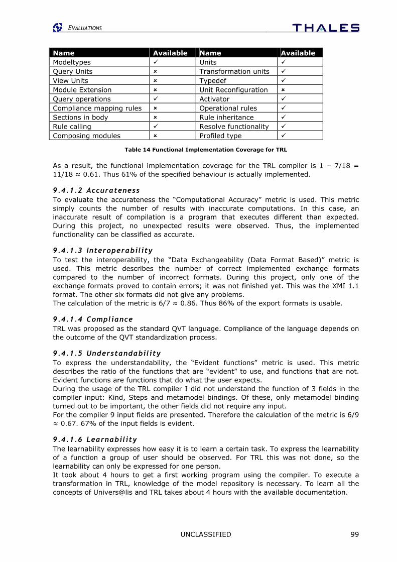
EVALUATIONS
Name Available Name Available Modeltypes Units Query Units Transformation units View Units Typedef Module Extension Unit Reconfiguration Query operations Activator Compliance mapping rules Operational rules Sections in body Rule inheritance Rule calling Resolve functionality Composing modules Profiled type
Table 14 Functional Implementation Coverage for TRL
As a result, the functional implementation coverage for the TRL compiler is 1 – 7/18 = 11/18 ≈ 0.61. Thus 61% of the specified behaviour is actually implemented.
9.4.1.2 Accurateness To evaluate the accurateness the “Computational Accuracy” metric is used. This metric simply counts the number of results with inaccurate computations. In this case, an inaccurate result of compilation is a program that executes different than expected. During this project, no unexpected results were observed. Thus, the implemented functionality can be classified as accurate.
9.4.1.3 Interoperability To test the interoperability, the “Data Exchangeability (Data Format Based)” metric is used. This metric describes the number of correct implemented exchange formats compared to the number of incorrect formats. During this project, only one of the exchange formats proved to contain errors; it was not finished yet. This was the XMI 1.1 format. The other six formats did not give any problems. The calculation of the metric is 6/7 ≈ 0.86. Thus 86% of the export formats is usable.
9.4.1.4 Compliance TRL was proposed as the standard QVT language. Compliance of the language depends on the outcome of the QVT standardization process.
9.4.1.5 Understandability To express the understandability, the “Evident functions” metric is used. This metric describes the ratio of the functions that are “evident” to use, and functions that are not. Evident functions are functions that do what the user expects. During the usage of the TRL compiler I did not understand the function of 3 fields in the compiler input: Kind, Steps and metamodel bindings. Of these, only metamodel binding turned out to be important, the other fields did not require any input. For the compiler 9 input fields are presented. Therefore the calculation of the metric is 6/9 ≈ 0.67. 67% of the input fields is evident.
9.4.1.6 Learnability The learnability expresses how easy it is to learn a certain task. To express the learnability of a function a group of user should be observed. For TRL this was not done, so the learnability can only be expressed for one person. It took about 4 hours to get a first working program using the compiler. To execute a transformation in TRL, knowledge of the model repository is necessary. To learn all the concepts of Univers@lis and TRL takes about 4 hours with the available documentation.
UNCLASSIFIED 99

EVALUATIONS
9.4.1.7 Operability The error messages in a compiler play an important role in the operability. The “Message understandability in use” metric, measures the amount of messages that is understandable, compared to the total amount of messages. The syntax errors of the compiler give a correct indication of the error. The line number in the code and the token not recognized is presented. The ordinary errors present rather cryptical messages such as “NoTransformationUnitForRule : _R3” The problem with this error is that it refers to rule _R3, but this rule is not in the TRL source, it is in the intermediate python code that is generated by the compiler. Also the warnings and AttributeErrors are difficult to read and to gain knowledge from. To conclude, only a small part of the error messages is easy to understand. In the case study, 1/4 = 0.25 of the types of messages is well understandable.
9.4.1.8 Time Behaviour For the time behaviour, the “Turnaround time” metric was used. The turnaround time is the time that the program consumes after the user executed a command. The Compilation of the code presented in Appendix E took on average 11 seconds on the machine that was described in section 8.5.4. The execution of transformation is also discussed in that section.
9.4.1.9 Installability The “Ease of installation” is the number of successful installations divided by the total number of installations. For this project, the software was only installed once. Thus, the metric results in 100% successful installations. However, if the installation is performed according to the installation manual, the software does not work. By default, the Apache webserver does not execute Python scripts. The manual does not describe how to let Apache handle Python scripts. So, the user must have some basic knowledge of Apache.
9.4.2 TRL Compi ler Qual i ty in Use Quality in use characteristics are more abstract characteristics, describing the attitude that the user of the software products gets from using it.
9.4.2.1 Effectiveness “Task effectiveness” measures what part of the tasks was completed successfully. In the case study, all the required tasks were completed, so the task effectiveness was 100%.
9.4.2.2 Productivity Typical productivity metrics measure the time needed to complete a task. In the case study no time measurements were done. It was remarkable, that the completion of a task was a time consuming activity. One expects that when the requirements for the transformation are clear, the implementation should not take much time. However, not only the desired result of the transformation must be clear, also exactly the way the transformation actions must be executed. Therefore the transformation execution must be designed and tested. This all took up a lot of extra time.
9.4.2.3 Satisfaction The satisfaction describes how satisfied the users of the software product are. Again this should be tested using a group of users. For this project, the software was only used by one person.
UNCLASSIFIED 100

EVALUATIONS
Personally I hoped that the complete language was implemented in the compiler, but it turned out that that was not the case (see paragraph 9.4.1.1). This was a disappointment. However, the parts of the compiler that were implemented seemed to work fine. Transformation could actually be executed on models and the result worked as required. To give a numeric value of the satisfaction, the average for some of the measured external metrics are used: Suitability, interoperability, understandability and operability respectively. This results in (0.61 + 0.86 + 0.67 + 0.25) / 4 ≈ 0.60.
9 .5 Summary This chapter presented the results from several evaluations. First the language TRL was evaluated using the requirements from the QVT RFP and the desired characteristics that were described in paragraph 4.4. Also an empiric evaluation of the language is presented. Finally, the TRL compiler was evaluated according to the software product quality standard ISO/IEC 9126.
UNCLASSIFIED 101

EVALUATIONS
UNCLASSIFIED 102
CONCLUSIONS & RECOMMENDATIONS
10 Conclusions & Recommendations
The purpose of this project was to evaluate the Transformation Rule Language (TRL). This chapter contains the conclusions and recommendations that are the direct result of the project’s activities. In the first paragraph the research subquestions are answered. Then, the main research questions are answered. Next, the overall conclusions are presented. And finally, recommendations for future work are discussed.
10 .1 Answers to the re search ques t ions In this paragraph the answers to the research questions are presented. For every topic, the chapter or paragraph that contains the answer is given. 1: The state of MDA MDA was discussed in chapter 3. Although MDA does not (yet) provide a full-grown solution to software development, the software industry is slowly taking on the concepts and several successful case studies using MDA are already reported. OMG did not give a definition of MDA. OMG laid down the concepts and the users should eventually define MDA. As a result, the concept is still evolving and currently it is not defined what MDA exactly is and what MDA is not. Therefore, it is not clear what is meant by the statement 100% MDA, something that certain software development products claim to be. Question 1.1: What is MDA? OMG’s MDA is an approach to system development that uses models not only for design, but also for the generation of systems. In other words, the models actually “drive” the development. In MDA the specification of a system is separated from the implementation details of the system on a certain platform. MDA is an “architecture”, as it describes the artifacts and the interaction of these artifacts in software development, but not the development process. However, MDA could be used as a basis for such a software development process. Such approaches are called Model Driven Engineering (MDE) or Model Driven Development (MDD). Question 1.2: What are the technologies used in MDA? Platform Independent Models (PIMs) specify a system independent of an underlying platform. Platform Specific Models (PSMs) describe the same system, but contain platform specific details. Although MDA can use different modeling languages, UML is commonly used as the modeling language for systems specifications. UML can be adapted to a specific domain by profiles or by MOF based extensions. The Meta Object Facility (MOF) provides a unifying way for describing, representing and manipulating meta-information. It provides a way to specify metamodels. As MDA is model-driven, MOF is an important concept in MDA. It can for example be used to specify UML or transformation languages. To use models to derive software, some process is needed that has models as input and generates other development artifacts. Model transformations are used to transform models to other models (see also question 2.1).
UNCLASSIFIED 103
CONCLUSIONS & RECOMMENDATIONS
Question 1.3: What are the different approaches to MDA? When using MDA, different approaches to modeling and different approaches to transformations can be used. Different techniques can be used to model a system. UML is a commonly used modeling language, but MDA can work with any language that is described in MOF. The level of detail in the models can also vary. In some approaches, PIMs contain all the information necessary to generate an executable application. While others transform PIMs to incomplete PSMs. Extra information must than be added to the generated PSM. Behavior in models can be modeled with behavioral models of UML, such as interaction diagrams, activity diagrams, sequence diagrams or state machines. Also, Action Semantics languages, such as the Action Semantics Language (ASL) from Kennedy Carter, provide the facility to model behavior. Ordinary programming languages can also express model behavior. However, some people consider the usage of programming languages as a violation of platform independency. Personally I do not see an essential difference between the usage of, for example, ASL and a programming language, such as Java, Python or C. The modeling of transformations can be done in several ways (see also question 2.1). The approaches differ not only in the way model transformations are expressed, but there are also several approaches to transformation execution. Model transformation languages provide a way to specify the transformations. Such languages are often textual languages, but also visual approaches exist. Question 1.4: What is the state of the art in MDA? No standard for the specification of transformations exists yet. The standardization process is in progress. Some tools provide the possibility to specify behavior in a tool-dependent way. Such tools can generate complete executable software from models. For model behavior several modeling techniques are available. One could use UML Action Semantics, State machines and other behavioral diagrams from UML, but also programming languages to express behavior in models. Most well-known software modeling tools now provide the facility to execute transformations on models. At least, structural elements from PSMs can be derived from structural PIMs and code skeletons for these models can be generated. 2: Transformations Answers to these questions come from chapter 4. Question 2.1: What techniques exist for model transformations? Five distinct transformation approaches are distinguished. • Graph based transformations are based on graph theory. Models are treated as graphs
and generic graph rewriting techniques are used to execute transformations. • XSLT can be used to transform models that are stored as XMI XML files. The
techniques and the processors for these techniques are already available. However, XSLT files are hard to read for humans.
• Several tools provide their own, tool-specific way to specify transformations. These transformations can be executed only on models that are stored in the tool. Such approaches often have a tool-specific language or API to express the transformations.
• A general-purpose programming language can be used to express transformations. As most languages do not have the capability to modify models, a specific model API is needed.
UNCLASSIFIED 104

CONCLUSIONS & RECOMMENDATIONS
• The last approach is the one that is discussed in this document. A tool-independent Domain Specific Language (DSL) for model transformation is a language that is specially designed to express model transformations. DSLs can have textual or visual representations.
Question 2.2: What are desired properties of transformations? To evaluate a transformation language, several properties were derived from the literature. Every characteristic was evaluated and as a result the characteristics are classified as “desirable” and as “useful, but not necessary” The following characteristics are desirable for model transformations: Tuneability, Traceability, Incremental consistency, Expressive power, Readability, Portability, Durability, Composition capability and the use of Open standards. The following property is proposed in several other documents, but is not always necessary to have: Bi-directionality. These characteristics are explained in detail in paragraph 4.4 on page 35. The evaluation of all these properties for TRL is described in paragraph 9.2 on page 95. 3: Queries Views and Transformations These question are answered using paragraph 3.2 and chapter 5. Question 3.1: What are the main differences between the proposals? Most proposals contain declarative languages, while TRL contains a large imperative part. This results in completely different approaches for the expression of transformations. In the declarative approach, the desired result is described; in an imperative approach the needed actions to get tot the result are described. Some languages, for instance TRL and QVT partners, make a distinction between relations, which are static constraints, and between operational mappings that are the dynamic actions of transformation. Other languages only have the declarative part and let the execution engine solve the execution problem. Only QVT-partners’ proposal contained a graphical notation for transformations. The others proposed a textual representation of transformations. Question 3.2: What is the idea behind Thales’ proposal? Constraints can best be specified using a declarative language. Implementations of transformations can better be expressed using an imperative language. Therefore, TRL contains conformance based, declarative rules beside operational, imperative rules. 4: Case study: Threat Evaluation in Anti Air Warfare, using DDS These question are answered using chapter 7. Question 4.1: Which components are involved in TE? To create a DDS-specific component such as Threat Evaluation (TE), a PIM, a Domain Object Model (DOM), a Topic Model (TM) and mappings between the several models are needed as input to create the application. Several transformation processes are used to create the software on the target platform. One transformation creates the DLRL code directly. The other transformations use PSMs as intermediate models. Information in the form of programming code must then be added to the PSM. The enriched PSM can be used to generate the application component code. These transformations are visualized in Figure 49 on page 65. Question 4.2: How do DDS and MDA fit into the picture?
UNCLASSIFIED 105

CONCLUSIONS & RECOMMENDATIONS
In MDA terminology, DDS is the platform for DDS applications. Applications are designed as DDS-independent models and DDS specific details are automatically introduced in the transformation process. Question 4.3: What transformations are needed in AAW? Two types of transformations are needed in AAW. • The generation of the DCPS and the DLRL can be executed without user interference.
This transformation is not considered in this thesis. • The other transformation is actually composed of two transformations: the
transformation from the PIM to PSM and the transformation from PSM to code. The PSM can be seen as an intermediate model. Additional information in the form of programming code is added to this PSM before the PSM-to-code transformation can be executed. This thesis focuses on the PIM-to-PSM transformation.
In MDA four methods of transformations are described: Manual Transformation, Transforming a PIM Using a Profile, Transformation Using Patterns and Markings and Automatic transformations. Also model merging is proposed as a model transformation technique. The transformation in AAW uses a combination of patterns, markings and automated execution. The marking of model elements is done using stereotypes. Transformation execution patterns are described in a transformation specification language or in a programming language. Finished transformations can be executed automatically without user intervention. Model merging is the technique that might be used to achieve conservative generation. New model are merged with existing ones. This process is out of the scope of this assignment. Question 4.4: How can these transformations be expressed using TRL? PIM-to-PSM transformations can be expressed in TRL. The transformation consists of a set of rules packaged in units. Every rule queries the source model and can create elements in the target model. Rules can also call other rules. A certain transformation approach is needed in TRL or any imperative approach. The approach divides the transformation process in phases that are dependent of each other. Every phase can be executed after the elements of the previous phase are created. This theses focused on a PIM-to-PSM model transformation. The other transformation in MIRROR, from DOM, TM and mappings to the DLRL code was not expressed in TRL. TRL was not developed to implement model to code transformations. The generation of code from models is not implemented in Univers@lis or the TRL compiler.
10 .2 Answers to the ma in re search ques t ions This section answers the main research questions that were formulated in section 2.3. “Can the language proposed in the QVT proposal that was submitted by Thales, TRL, be used to describe transformations from PIMs to PSMs in a TE component based on DDS?” Yes, TRL can be used to describe transformations from PIMs to PSMs for a DDS based TE component. The case study indicated that the required transformations can be expressed in the language.
UNCLASSIFIED 106

CONCLUSIONS & RECOMMENDATIONS
“Furthermore, does the language have properties that are desirable in a transformation language?” TRL has several properties that are desirable in a model transformation language.
• TRL has a specific filtering construct. Filtering is used on a set and the result is a set with all the elements filtered out that do not pass the filtering expression. A line such as self.ownedElement[Class and generalization] results in a set with only Class elements that have a generalization.
• TRL uses the arrow operator (->) from OCL. The operator can be used to “spread a message”. This spreading means that the rule that comes after the arrow is executed for every element in the set. This construct combined with the filtering results in compact statements.
• The tuneability of TRL is good. Rules and units can use parameters in several ways. Furthermore, models can contain markings that guide the execution of the transformation.
TRL has also some characteristics that are not desirable in a model transformation language.
• Rule inheritance is a low level inheritance mechanism that can be used to extend existing rules. However, in rule inheritance it is not possible to refer to variables that were defined in the parent rule. The case study revealed that practical usage of rule inheritance was limited because of this restriction.
• TRL programs must be structured in a certain way. For every metamodel element that is involved in the transformation, at least one rule must be specified. This structure results in a program in which the flow of control is difficult to follow. It jumps from rule to rule. This has a negative influence on the readability.
• The rule execution order must be explicitly specified by hand. This means that the transformation developer must be aware of this ordering.
• Elements in models are somehow connected to other elements. Attributes are connected to classes, classes to packages, etc. This structure must be explicit programmed in TRL for every element. When an element is not explicitly placed in the model, the element is ‘lost’. It is not visible in the model.
• In the context of transformations, two types of traceability are available: Traceability during transformation and traceability after the transformation. Traceability after the transformation is not available in the current implementation, but that could be solved by enhancing the software. The other type of traceability, traceability during transformation, is available in TRL. The auxiliary functions to deal with the traceability have a limited functionality. For example, resolve() can only filter elements by their type.
• TRL does not provide a way to clone an element. A transformation developer must write a metamodel dependent clone operation for every metamodel element. To specify complete transformations in TRL a lot of code is needed.
Finally some characteristics were not particular positive or negative, the neutral characteristics.
• TRL’s units can be extended or composed of other units. • The learnability of the language is good for people with a computer science
background. For people without knowledge of packages, methods, variables, etc. the language is not very easy to learn and use.
UNCLASSIFIED 107

CONCLUSIONS & RECOMMENDATIONS
10 .3 Conc l u s ions TRL has some characteristics that are desirable in model transformations. Some typical model transformation actions can be expressed in a compact way. However, the language has a number of negative characteristics that decrease the usability of the language. The current implementation of the TRL compiler translates TRL code to intermediate Python code. The design of TRL might have been influenced by the structure of Python. At least, the languages have great similarities in functionality and structure. Because the operational rules of TRL are imperative, a transformation developer runs into the same problems that would occur with a general-purpose language. The order of execution of the rules is such a problem. TRL does not help the developer to solve this problem. The TRL compiler is built on top of the Univers@lis model repository. In the current implementation, transformations can only have one model as input and one model as output. In practical use, one might need information from several input models to create several output models. The TRL compiler does not store traceability links after the transformation. To provide incremental consistency or conservative generation, the links between source and target elements must be stored and be accessible, not only during, but also after the transformation execution. Conservative generation is a very important feature that must be available in order to be used in real software development projects. The TRL software is obviously a prototype and user documentation is hardly available. All these characteristics of the language and the software indicate that TRL is not ready to be used in software development projects yet. Declarative model transformation languages were out of scope in this assignment. However, declarative languages might be interesting to explore. In declarative languages, the problem is described and not the solution. The problem solving must be solved at the execution environment side. Therefore the transformation development could be easier. This thesis focused on structural model transformations. Behavior in models was out of scope. The addition of behavior to PIMs provides the facility to generate complete applications. Several approaches to behavior modeling in models already exist. One could use state machines, activity diagrams, interaction diagrams, Action Semantics languages or programming languages to describe behavior. Especially, model behavior in transformations is worth further investigation. The MDA guide proposes four methods to transformations: Manual Transformation, Transforming a PIM Using a Profile, Transformation Using Patterns and Markings and Automatic transformations. The transformation approach within MIRROR uses a combination of these approaches. MIRROR uses Profiles, Patterns and Marking and Automatic transformations to produce the target PSM from the source PIM. The case study proved that these techniques from the MDA guide have enough expressive power to execute transformations. In MIRROR the advantages of the usage of a PSM becomes clear. The PIM does not contain enough information and additional information is added in the PSM. Here, two roles in the MDA process appear: the PIM developer and the transformation developer. The transformation from PIM to PSM and from PSM to code should eventually be transparent to the PIM developer. In the ideal situation software is directly generated from human readable and understandable PIMs. MIRROR currently uses an approach to model transformations that was not presented as a proposal for QVT. The general-purpose language Java [51] is used with a model specific API, provided by the Eclipse Modeling Framework. This approach is implemented with satisfactory results in MIRROR. So, it is strange that no proposal contains such an approach.
UNCLASSIFIED 108

CONCLUSIONS & RECOMMENDATIONS
Personally I prefer a standard, platform independent model transformation API, instead of a standard model transformation language. Although such a language could be implemented on several platforms, one is dependent on the new language. When only the model transformation API is standardized, any language could be used, if a platform specific implementation is available. Model transformations will probably get standardized soon after this assignment. The usability and usage of the standard will stand or fall with the acceptance of the standard in software development software, such as modeling tools and IDEs. I think that MDA is “another approach to software engineering” that definitely has some desirable characteristics, but is does not introduce revolutionary new concepts. In MDA systems are described at different abstraction levels and models are directly used in transformations. This provides a means to keep design, documentation and code consistent, which is desirable. However, the MDA approach resembles existing, tool-dependent, approaches. Modern IDEs also have the capability to create design models, add behavior to these models and generate the application. The addition of MDA to this is the description of a system at different levels of abstraction and the standardization process to get a tool-independent approach. Especially the focus on platform independent models provides a means to generate applications for several platforms based on one design model.
10 .4 Recommendat ions The practical recommendations are divided into recommendations for Thales and recommendations for TRL developers.
10.4.1 Thales MIRROR MIRROR currently uses Java in XDE with the Eclipse Modeling Framework to write and execute model transformations. The expressiveness of Java is similar to that of TRL for model transformations. Some comparisons between typical expressions in both languages are show in Appendix H. Because of this similarity and the maturity of the Java language and development software, I advise to continue using Java in the project. If the project wants to change the approach to model transformations, I should at least wait until Queries, Views and Transformations are standardized. The latest announcement was that QVT will be standardized in the 4th quarter of 2004. As the purpose of DDS was to standardize data distribution, a standardized approach for transformations in the project is desirable. During the assignment, once again, it became clear that the naming of artifacts is very important. For example, the name PIM-to-DOM mapping suggests an action, while the name PIM-to-DOM mapping model suggests a more static artifact. Acronyms that are the same as existing ones are confusing. The Domain Object Model (DOM) has the same abbreviation as the well-known Document Object Model from XML. Domain Model or Object Domain Model could be used to describe the current Domain Object Model and has a different abbreviation.
UNCLASSIFIED 109

CONCLUSIONS & RECOMMENDATIONS
10.4.2 TRL developers To deal explicitly with the problem of rule execution order, the concepts of “phases” could be introduced. Rules can be placed in a certain phase and phases can be dependent of each other. To start the execution of a phase, all phases that it depends on must be finished. The functionality to refer to elements that are already created in a model is badly documented currently. Functions such as resolve, resolveone and at and the update facility provide facilities that enhance the usability of the language. However, the documentation for these functions is poor. Improvement of these parts of the documentation results in better usability of the language. The application of MDA in a real project demands for the storage of traceability links. The links from a source element to target elements must be transient and not only available during transformation execution. Storage of traceability links should be added to TRL. One approach to store links between UML models is the usage of UML Dependencies as described in paragraph 7.3.2.4 on page 68. In the current approach with the Univers@lis repository, only one model can be used as input model. In MDA several models, with different metamodels, can be input to a transformation. The availability to use several input model improves the practical applicability of the software.
UNCLASSIFIED 110

CONCLUSIONS & RECOMMENDATIONS
UNCLASSIFIED 111


REFERENCES
References
[1] Alcatel, Softeam, Thales, TNI-Valiosys, Codagen Technologies Corp (2003), Response to the MOF 2.0 Query/Views/Transformations RFP, revised submission (ad/2002-04-10), Object Management Group.
[2] Ammers, A. van (2003), Software Development using Platform Independent Models in the Model Driven Architecture, Thales Naval Nederland/University of Twente
[3] Appukuttan, Biju, Clark, Tony, Sreedhar, Reddy, Tratt, Laurence, Venkatesh, R (2003), A model driven approach to building implementable model transformations, QVT-Partners.
[4] Assmann, Uwe, Christoph, Alexander (2001), About UML transformations based on Graph Rewriting Systems.
[5] Belaunde, Mariano, A Pragmatic Approach for Building a User-fiendly and Flexible UML Model Repository, France Telecom CNET.
[6] Bray, Tim, Paoli, Jean, Sperberg-McQueen, C.M., Maler, Eve (eds.) (2000), Extensible Markup Language (XML) 1.0 (Second Edition), World Wide Web Consortium (W3C).
[7] Carter, Kennedy (2002), Supporting Model Driven Architecture with executable UML, Kennedy Carter.
[8] Compuware Corporation, SUN Microsystems (2003), XMOF, Queries, Views and Transformations on Models using MOF, OCL and Patterns, ad/2003-08-07.
[9] Czarnecki, Krysztof, Helsen, Simon (2003), Classification of Model Transformation Approaches, University of Waterloo, Canada.
[10] Deursen, van, A, Klint, P (1998), Little Languages: Little maintenance, Journal of Software maintenance, pp-75-93.
[11] DSTC, IBM (2003), MOF Query / Views / Transformations, First Revisited Submission, document number ad/2003-08-03.
[12] EMF, Eclipse Modeling Framework, retrieved May 2004, from www.eclipse.org/emf
[13] Exertier, Daniel, Fafournoux, Emmanuel, Jouenne, Eric, Langlois, Benoît, Normand, Véronique (2003), MIRROR Handbook, Thales.
[14] Fowler, Martin (1998), UML distilled, Addison-Wesley.
[15] France Telecom, Univers@lis Model Repository, retrieved March 2004, from http://universalis.elibel.tm.france.
[16] Frankel, David S. (2003), Model driven architecture, Applying MDA to enterprise computing, Wiley.
UNCLASSIFIED I
REFERENCES
[17] Gamma, Erich et al. (1995), Design Patterns: elements of reusable object-oriented software, Addison-Wesley.
[18] Gardner, Tracy, Griffin, Catharina, Koehler, Jana, Hauser, Rainer (2003), A review of OMG MOF 2.0 Query / Views / Transformations Submissions and Recommendations towards the final standard, IBM.
[19] Grose, Timothy J (2003), Mastering XMI, Java Programming with XMI, XML, and UML, OMG Press.
[20] Hag, J.H. van ‘t (2004), Data-centric to the max, The SPLICE architecture experience, Thales Naval Nederland.
[21] IBM/Rational, XDE resources, retrieved March 2004, from http://www-136.ibm.com/developerworks/rational/products/xde
[22] Interactive Objects Software GmbH, Project Technology Inc., Unisys Corporation (2004), 2nd Revised Submission to MOF Query / View / Transformation RFP.
[23] Interactive Objects, ArcStyler, retrieved March 2004, from http://www.arcstyler.com/
[24] ISO/IEC (2001), ISO/IEC 9126-1 Software engineering – Product quality, part 1: Quality model.
[25] ISO/IEC (2001), ISO/IEC 9126-2 Software engineering – Product quality, part 2: External metrics.
[26] ISO/IEC (2001), ISO/IEC 9126-4 Software engineering – Product quality, part 4: Quality in use metrics.
[27] Jacobson, Ivar, Booch, Grady, Rumbaugh, James (1999), The Unified Software Development Process, Addison Wesley Longman, Inc.
[28] Karsai, Gabor, Agrawal, Aditya (2003), Graph Transformations in OMG’s Model-Driven Architecture, Vanderbilt University, Nashville, TN, USA.
[29] Kleppe, Anneke; Warmer, Jos; Bast, Wim (2003), MDA Explained, Addison-Wesley.
[30] Kruchten, Philippe (1998), The Rational Unified Process, An Introduction, Addison-Wesley.
[31] Krueger, C.W. (1992), Software Reuse, ACM computing Surveys, 24(2):131-182, June 1992.
[32] Miller, Joaquin, Mukerji, Jishnu (2001) (Eds.). MDA Model Driven Architecture (ormsc/2001-07-01), Object Management Group.
[33] Miller, Joaquin, Mukerji, Jishnu (2003) (Eds.). MDA Guide version 1.0.1 (omg/2003-06-01), Object Management Group.
[34] Mirror TNNL (2004), DLRL Development, version 5, 04-05-2004.
UNCLASSIFIED II
REFERENCES
[35] OMG (2001), Common Warehouse Metamodel (CWM) Specification ad/2001-02-01.
[36] OMG (2002), Meta Object Facility (MOF) Specification, version 1.4.
[37] OMG (2002), Request for Proposal: MOF 2.0 Query / Views / Transformations RFP (ad/2002-04-10).
[38] OMG (2002), XML Metadata Interchange (XMI) Specification, (v1.2) (formal/02-01-01).
[39] OMG (2003), 2nd revised submission to OMG RFP ad/00-09-02: Unified Modeling Language: Superstructure (version 2.0), (ad/2003-01-02).
[40] OMG (2003), 3rd revised submission to OMG RFP ad/00-09-01: Unified Modeling Language: Infrastructure (version 2.0), (ad/2003-01-01).
[41] OMG (2003), Data Distribution Service for Real-Time Systems Specification, (final adopted specification ptc/03-07-07).
[42] OMG (2003), Response to the UML 2.0 OCL RfP (ad/2000-09-03), Revised submission version 1.6, (ad/2003-01-07).
[43] OMG (2003), Unified Modeling Language: Infrastructure, version 2.0, (ad/2003-01-01).
[44] OMG (2003), Unified Modeling Language: Superstructure, version 2.0 (ad/2003-01-02).
[45] OMG (2004), Model Driven Architecture, retrieved January, from http://www.omg.org/mda
[46] OMG, OMG Unified Modeling Language Resource Page, retrieved January, 2004, from http://www.omg.org/uml
[47] Schuurman, E (2003), Stageverslag Scenario Simulation Generator, Thales Naval Nederland.
[48] Sendall, S., Wojtek, K. (2003), Model Transformation – the Heart and Soul of Model-Driven Software Development.
[49] Softeam (2000), Guarantee permanent Model/Code consistency: Model Driven Engineering versus Roundtrip Engineering.
[50] Softeam, Objecteering/UML Modeler, Objecteering/XMI User Guide, Objecteering/UML Profile Builder, Objecteering/J Language User Guide, Objecteering/UML Modeler User Guide, Objecteering/Introduction User Guide.
[51] SUN, The Java website, retrieved 13-06-2004, from http://java.sun.com
[52] T. Clark, A. Evans, S. Kent, P. Sammut (2001), The MMF Approach to Engineering Object-Oriented Design Languages, Workshop on Language Descriptions, Tools and Applications (LDTA2001), April, 2001. of “Engineering Modeling Languages: A precise Meta-Modeling Approach”.
UNCLASSIFIED III

REFERENCES
[53] Thales, Thales Nederland B.V. corporate website, retrieved June 2004, from http://tnlweb.nl.thales/
[54] TRESE, Twente Research and Education on Software Engineering (TRESE) Website, retrieved June 2004, from http://trese.cs.utwente.nl
[55] Tretmans, Jan, Testing with Formal Methods, Formal Methods & Tools Group, Faculty of Computer Science, University of Twente.
[56] Wickipedia, online dictionary, retrieved July 2004, from http://en.wickipedia.org
[57] World Wide Web Consortium (W3C) XSL Transformations (XSLT) Specification, version 2, Working Draft.
UNCLASSIFIED IV
GLOSSARY
Glossary
Abstract Syntax: A description of the structures that can be expressed in a language.
Abstraction: Omission of detail from a description. The opposite of refinement [2].
Association: The semantic relationship between two or more classifiers that specifies connections among their instances [36].
Bi-directionality: The ability to perform transformations in two ways.
Composition capability: The capacity to compose transformations from other, existing transformations.
Concrete Syntax: A description of the textual or visual syntax of language.
Declarative programming: a sort of programming that describes to the computer a set of conditions and lets the computer figure out how to satisfy them [56].
Diagram: A graphical presentation of a collection of model elements, most often rendered as a connected graph of arcs (relationships) and vertices (other model elements). UML supports the following diagrams: class diagram, object diagram, use case diagram, sequence diagram, collaboration diagram, state diagram, activity diagram, component diagram, and deployment diagram [36].
Domain Specific Language: A language that is tailored to a specific domain
Domain: An area of knowledge or activity characterized by a set of concepts and terminology understood by practitioners in that area [36].
Durability: The ability to endure for a certain amount of time.
Element: An atomic constituent of a model [36].
Expressiveness: The ability to express certain things in a language.
Generalization: A taxonomic relationship between a more general element and a more specific element. The more specific element is fully consistent with the more general element and contains additional information. An instance of the more specific element may be used where the more general element is allowed. See: inheritance [36].
Imperative programming: A sort of programming employing side effect as central execution feature [56].
Implementation: A definition of how something is constructed or computed. For example, a class is an implementation of a type, a method is an implementation of an operation [36].
Incremental Consistency: The ability to perform transformations that do not overwrite existing elements.
Inheritance: The mechanism by which more specific elements incorporate structure and behavior of more general elements related by behavior. See generalization [36].
Mapping: Specification of a mechanism for transforming the elements of a model conforming to a particular metamodel into elements of another model that conforms to another (possibly the same) metamodel.
UNCLASSIFIED V
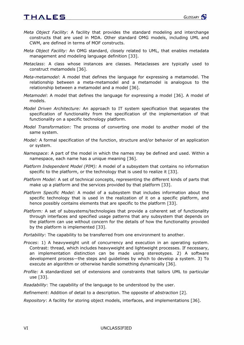
GLOSSARY
Meta Object Facility: A facility that provides the standard modeling and interchange constructs that are used in MDA. Other standard OMG models, including UML and CWM, are defined in terms of MOF constructs.
Meta Object Facility: An OMG standard, closely related to UML, that enables metadata management and modeling language definition [33].
Metaclass: A class whose instances are classes. Metaclasses are typically used to construct metamodels [36].
Meta-metamodel: A model that defines the language for expressing a metamodel. The relationship between a meta-metamodel and a metamodel is analogous to the relationship between a metamodel and a model [36].
Metamodel: A model that defines the language for expressing a model [36]. A model of models.
Model Driven Architecture: An approach to IT system specification that separates the specification of functionality from the specification of the implementation of that functionality on a specific technology platform.
Model Transformation: The process of converting one model to another model of the same system.
Model: A formal specification of the function, structure and/or behavior of an application or system.
Namespace: A part of the model in which the names may be defined and used. Within a namespace, each name has a unique meaning [36].
Platform Independent Model (PIM): A model of a subsystem that contains no information specific to the platform, or the technology that is used to realize it [33].
Platform Model: A set of technical concepts, representing the different kinds of parts that make up a platform and the services provided by that platform [33].
Platform Specific Model: A model of a subsystem that includes information about the specific technology that is used in the realization of it on a specific platform, and hence possibly contains elements that are specific to the platform [33].
Platform: A set of subsystems/technologies that provide a coherent set of functionality through interfaces and specified usage patterns that any subsystem that depends on the platform can use without concern for the details of how the functionality provided by the platform is implemented [33].
Portability: The capability to be transferred from one environment to another.
Proces: 1) A heavyweight unit of concurrency and execution in an operating system. Contrast: thread, which includes heavyweight and lightweight processes. If necessary, an implementation distinction can be made using stereotypes. 2) A software development process—the steps and guidelines by which to develop a system. 3) To execute an algorithm or otherwise handle something dynamically [36].
Profile: A standardized set of extensions and constraints that tailors UML to particular use [33].
Readability: The capability of the language to be understood by the user.
Refinement: Addition of detail to a description. The opposite of abstraction [2].
Repository: A facility for storing object models, interfaces, and implementations [36].
UNCLASSIFIED VI
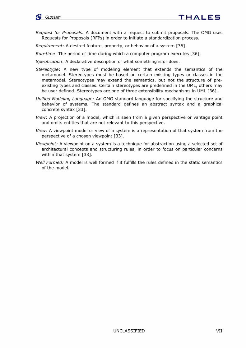
GLOSSARY
Request for Proposals: A document with a request to submit proposals. The OMG uses Requests for Proposals (RFPs) in order to initiate a standardization process.
Requirement: A desired feature, property, or behavior of a system [36].
Run-time: The period of time during which a computer program executes [36].
Specification: A declarative description of what something is or does.
Stereotype: A new type of modeling element that extends the semantics of the metamodel. Stereotypes must be based on certain existing types or classes in the metamodel. Stereotypes may extend the semantics, but not the structure of pre-existing types and classes. Certain stereotypes are predefined in the UML, others may be user defined. Stereotypes are one of three extensibility mechanisms in UML [36].
Unified Modeling Language: An OMG standard language for specifying the structure and behavior of systems. The standard defines an abstract syntax and a graphical concrete syntax [33].
View: A projection of a model, which is seen from a given perspective or vantage point and omits entities that are not relevant to this perspective.
View: A viewpoint model or view of a system is a representation of that system from the perspective of a chosen viewpoint [33].
Viewpoint: A viewpoint on a system is a technique for abstraction using a selected set of architectural concepts and structuring rules, in order to focus on particular concerns within that system [33].
Well Formed: A model is well formed if it fulfills the rules defined in the static semantics of the model.
UNCLASSIFIED VII

GLOSSARY
UNCLASSIFIED VIII

APPENDICES
Appendices
Appendix A contains additional information about the transformations that are used in MIRROR. Some examples are used to clarify the needed transformations. Appendix B contains the syntax file that is used for the editor EditPlus. This syntax file can be used to acquire syntax highlighting for TRL in EditPlus. Appendix C contains the code of a PIM-to-PSM transformation expressed in J. The transformation was created in the first phase of the project to gain some experience with model transformations and with the possibilities. Appendix D contains the TRL specification. The specification is the grammar of TRL expressed in EBNF. Appendix E contains the mini Threat Evaluation PIM-to-PSM transformation expressed in TRL. Appendix F contains the Linux shell scripts that were used to use the command line functionality of the TRL compiler and of Univers@lis. Appendix G contains PIM-to-PSM transformation scenarios that were described at the first phase of the project. One of these scenarios is the one that eventually was used during the assignment.
UNCLASSIFIED IX

APPENDICES
UNCLASSIFIED X

APPENDICES
Appendix A Case Study description
This appendix contains example diagrams that show some PIMs and PSMs. The purpose of these diagrams is to get an idea of the required transformations in MIRROR. All images in this appendix are based in figures from [34]. These pictures were subject to many changes during the project. The pictures should therefore not be used as a specification for transformations, but they should be observed to get an idea of the required transformations.
Application
ThreatEvaluator
ThreateningItem
ThreateningItem3D
OwnS hipThreat
TE
*
pThreateningItem3D
_ThreatEvaluator
pOwnShip1
_Thread
*
*_ThreateningItem3D
*
Figure 65 Threat Evaluation PIM
OwnS hip ThreadEvaluatorThreat
getXPosition()getYPosition()setXPosition()setYPosition()addThreat()resetNewIndicationFlag()findThreat()p rocessThreat()cleanup OldThreats()
<<distributed>> xPosition : integer<<distributed>> yPosition : integer setTreateningItemList()
setItemToDefendList()initTimer()timerEvent()
resetNewIndicationFlag()getPredictedTimeOfImpact()setPredictedTimeOfImpact()getThreadValue()setThreadValue()setThreateningItem3D()getThreateningItem3D()setNewIndicationFlag()
Figure 66 Detailed PIM classes: OwnShip, Threat and ThreadEvaluator
UNCLASSIFIED XI

APPENDICES
:App lication :ThreadEvaluator TI:ThreateningItem :OwnShip Existing:Threat
<<comment>>For all Threads
Instance:TE
New:Threat
<<comment>>Proces the new Threat
<<comment>>For all Threatening Items
<<comment>>If threatening
<<comment>>If Threat exists then update the Threat else add the Threat
<<comment>>Remove all Threat with newIndicationFlag = false
<<comment>>Periodically ThreatEvaluationis executed
<<comment>>based on direction and sp eed
<<comment>>Based on timeOfImp act
resetNewIndicationFlag
resetNewIndicationFlag
getAllThreateningItems
areYouAThread
computeThreadValue
getXPosition
getYPosition
CreateAction
setThreadValue
setPredictedTimeOfImp act
setThreateningItem3D
processThreat()
findThreat
getThreateningItem3D
getIdentifier
addThreat
setNewIndicationFlag
cleanupOldThreats
TimerEvent
Figure 67 Threat Evaluation sequence diagram (incomplete)
ApplicationComponent
TE_Application TE_ThreatEvaluator
TE_ThreateningItem3D
TE_ThreateningItem
TE_ThreatTE_OwnS hip
_TE_ThreatEvaluator
1
_TE_ThreateningItem3D*_TE_OwnShip0..1
Figure 68 Threat Evaluation PSM (Application Component part)
UNCLASSIFIED XII
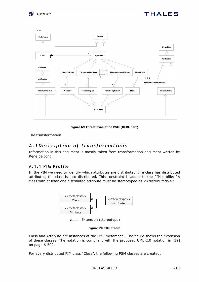
APPENDICES
DLRL
CacheAccess
Cache
Relation
ObjectHome
ObjectLink
RefRelation
Collection
ListRelation
OwnShipHome ThreateningItemHome ThreateningItem3DHome ThreatHome
ThreateningItem3DRelation
ThreatRelationThreatListRelation ThreateningItem ThreateningItem3D Threat
ObjectRoot
OwnShip
* * * *
0..1
*
1
1
*
1
1
ListRelation
ThreateningItem3DHome
ThreateningItem3DRelation
ThreateningItem3D
0..1
CacheAccess
Cache
Relation
ObjectHome
Collection
OwnShipHome ThreateningItemHome
1
1
*
1
ObjectLink
RefRelation
ThreatHome
ThreatListRelation ThreateningItem
ObjectRoot
OwnShip
* * *
1ThreatRelationThreat
*
*
Figure 69 Threat Evaluation PSM (DLRL part)
The transformation
A.1 Desc r ip t ion o f t rans fo rmat ions Information in this document is mostly taken from transformation document written by Rene de Jong.
A.1.1 PIM Prof i le In the PIM we need to identify which attributes are distributed. If a class has distributed attributes, the class is also distributed. This constraint is added to the PIM profile: “A class with at least one distributed attribute must be stereotyped as <<distributed>>”.
<<metaclass>>
Class <<stereotype>>
distributed
<<metaclass>>
Attribute
Extension (stereotype)
Figure 70 PIM Profile
Class and Attribute are instances of the UML metamodel. The figure shows the extension of these classes. The notation is compliant with the proposed UML 2.0 notation in [39] on page 6-502. For every distributed PIM class “Class”, the following PSM classes are created:
UNCLASSIFIED XIII

APPENDICES
• D_Class • D_ClassHome • D_ClassRef • D_ClassList
This list is not complete. Only the classes needed for the Mini Threat evaluation are shown.
A.1.2 PIM to PSM trans format ions Figure 71 shows the basic transformation for a distributed Class. The local attributes are placed in the application component, the distributed attributes are in the DLRL component. Every class placed in the DLRL component has a typical relationship with it’s home, ObjectHome and ObjectRoot as shown in the picture.
<<distributed>>MyClass
localAttribute : <<distributed>>
distributedAttribute : localM ethod()getLocalAttribute()setLocalAttribute()getDistributedAttribute()setDistributedAttribute()
App lication Component
App_MyClass
localAttribute : undefined
localM ethod()getLocalAttribute()setLocalAttribute()
DLRL
D_MyClass
ObjectRoot
ObjectHome
MyClassHome
distributedAttribute : undefined
getDistributedAttribute()setDistributedAttribute()
extend
*
App_MyClass
D_MyClass
localAttribute : <<distributed>>
distributedAttribute : localM ethod()getLocalAttribute()setLocalAttribute()getDistributedAttribute()setDistributedAttribute()
ObjectRoot
ObjectHome
MyClassHome
localAttribute : undefined
localM ethod()getLocalAttribute()setLocalAttribute()
distributedAttribute : undefined
getDistributedAttribute()setDistributedAttribute()
extend
*
PIM PSM
Figure 71 Basic PIM PSM transformation
Figure 72 shows the transformation needed to implement a generalization in the PIM. The objects in the DLRL layer are needed to fetch the information from parent attributes. In the TE case a generalization is used between a ThreateningItem and a ThreateningItem3D. ThreateningItem has a x-position and a y-position. ThreateningItem3D is a ThreateningItem that has a z-position added. To store the information of a ThreateningItem3D, two separate topics are stored in the system. One for a ThreateningItem and one for a ThreateningItem3D object/topic.
UNCLASSIFIED XIV

APPENDICES
Ap plication Comp onent
App_MyClassA App_MyClassB
DLRL
D_MyClassA D_MyClassB
MyClassAHome MyClassBHome
ObjectHome
ObjectRoot
1child
parent
1
**
1
<<distributed>>MyClassA
<<distributed>>MyClassB
App_MyClassA
D_MyClassA
MyClassAHome
ObjectHome
ObjectRoot
*
1
child
parent
App_MyClassB
D_MyClassB
MyClassBHome
*
PIM PSM
Figure 72 PIM PSM Generalization transformation
If a class A has an association to another class B, the association is stored in the DLRL as a refB object. The refB object is a reference to the object of type B. In A not a reference to object B is stored, but a reference to it’s reference: refB. For the programmer this ‘under water’ construct is not visible. Objects can simply call functions on other objects they have references to. This construction is used because not all objects are available in the DLRL at runtime. If an object is not needed in the local application it won’t be available in the DLRL. When a function on the objects is called the object is fetched from the DCPS and the function is executed.
PIM PSM
<<distributed>>MyClassA
<<distributed>>MyClassB
Application Component
DLRL1
App_MyClassA App_MyClassB
D_MyClassA D_MyClassB
ClassBRef
1
1
Figure 73 PIM PSM Association with multiplicity one
If a class A references a collection of B’s this relation is stored in a List object. The list object is a list of refB objects. This is shown in Figure 74.
UNCLASSIFIED XV

APPENDICES
PIM PSM
<<distributed>>MyClassA
<<distributed>>MyClassB
Application Component
App_MyClassA App_MyClassB
DLRL
D_MyClassA D_MyClassB
ClassBList ClassBRef
1
*
*
App_MyClassA App_MyClassB
D_MyClassA D_MyClassB
ClassBList ClassBRef
1
*
Figure 74 PIM PSM Association with multiplicity many
The constructs in this appendix are all the constructs that are used in the mini Threat Evaluation. As the name suggests, the mini Threat Evaluation is a rather small subset of a complete threat evaluation that is implemented.
UNCLASSIFIED XVI
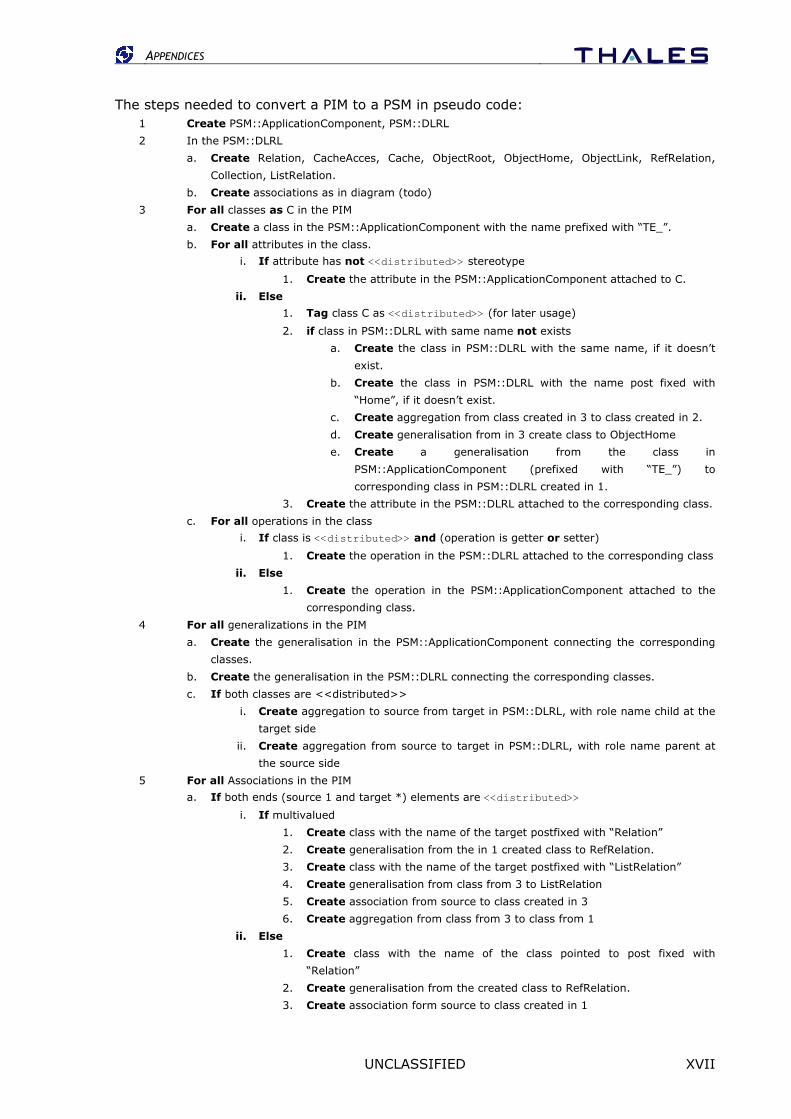
APPENDICES
The steps needed to convert a PIM to a PSM in pseudo code: 1 Create PSM::ApplicationComponent, PSM::DLRL
2 In the PSM::DLRL
a. Create Relation, CacheAcces, Cache, ObjectRoot, ObjectHome, ObjectLink, RefRelation,
Collection, ListRelation.
b. Create associations as in diagram (todo)
3 For all classes as C in the PIM
a. Create a class in the PSM::ApplicationComponent with the name prefixed with “TE_”.
b. For all attributes in the class.
i. If attribute has not <<distributed>> stereotype
1. Create the attribute in the PSM::ApplicationComponent attached to C.
ii. Else
1. Tag class C as <<distributed>> (for later usage)
2. if class in PSM::DLRL with same name not exists
a. Create the class in PSM::DLRL with the same name, if it doesn’t
exist.
b. Create the class in PSM::DLRL with the name post fixed with
“Home”, if it doesn’t exist.
c. Create aggregation from class created in 3 to class created in 2.
d. Create generalisation from in 3 create class to ObjectHome
e. Create a generalisation from the class in
PSM::ApplicationComponent (prefixed with “TE_”) to
corresponding class in PSM::DLRL created in 1.
3. Create the attribute in the PSM::DLRL attached to the corresponding class.
c. For all operations in the class
i. If class is <<distributed>> and (operation is getter or setter)
1. Create the operation in the PSM::DLRL attached to the corresponding class
ii. Else
1. Create the operation in the PSM::ApplicationComponent attached to the
corresponding class.
4 For all generalizations in the PIM
a. Create the generalisation in the PSM::ApplicationComponent connecting the corresponding
classes.
b. Create the generalisation in the PSM::DLRL connecting the corresponding classes.
c. If both classes are <<distributed>>
i. Create aggregation to source from target in PSM::DLRL, with role name child at the
target side
ii. Create aggregation from source to target in PSM::DLRL, with role name parent at
the source side
5 For all Associations in the PIM
a. If both ends (source 1 and target *) elements are <<distributed>>
i. If multivalued
1. Create class with the name of the target postfixed with “Relation”
2. Create generalisation from the in 1 created class to RefRelation.
3. Create class with the name of the target postfixed with “ListRelation”
4. Create generalisation from class from 3 to ListRelation
5. Create association from source to class created in 3
6. Create aggregation from class from 3 to class from 1
ii. Else
1. Create class with the name of the class pointed to post fixed with
“Relation”
2. Create generalisation from the created class to RefRelation.
3. Create association form source to class created in 1
UNCLASSIFIED XVII

APPENDICES
b. Else
i. Create association in the PSM::ApplicationComponent (same as source)
Operation
Property
ValueS pecification
Association
ownedOperation
association
2..*
memberEnd
0..1
ExtensionEnd
Extension
/extension
ownedEnd
ownedAttribute*
<<comment>>IS A Property (from Constructs)
<<comment>>IS A Association (from Constructs)
1
1
Class
Classifier
Generalization
1
specific
generalisation
general 1
**
class0..1
/metaclass
1
class
0..1
S tereotype
type1
*
owningAssociation0..1
ownedEnd
0..1
0..1 defaultValue
Figure 75 Relevant UML classes
UNCLASSIFIED XVIII
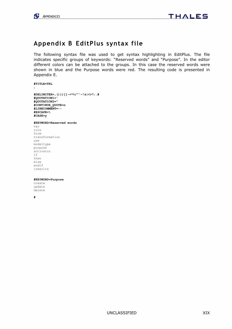
APPENDICES
Appendix B EditPlus syntax file
The following syntax file was used to get syntax highlighting in EditPlus. The file indicates specific groups of keywords: “Reserved words” and “Purpose”. In the editor different colors can be attached to the groups. In this case the reserved words were shown in blue and the Purpose words were red. The resulting code is presented in Appendix E. #TITLE=TRL ; #DELIMITER=,(){}[]-+*%/"'~!&|<>?;.# #QUOTATION1=' #QUOTATION2=" #CONTINUE_QUOTE=n #LINECOMMENT=-- #ESCAPE=\ #CASE=y #KEYWORD=Reserved words var rule from transformation use modeltype purpose activator if then else endif inherits #KEYWORD=Purpose create update delete #
UNCLASSIFIED XIX

APPENDICES
UNCLASSIFIED XX
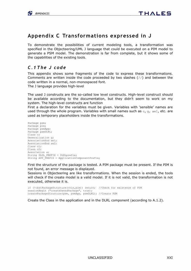
APPENDICES
Appendix C Transformations expressed in J
To demonstrate the possibilities of current modeling tools, a transformation was specified in the Objecteering/UML J language that could be executed on a PIM model to generate a PSM model. The demonstration is far from complete, but it shows some of the capabilities of the existing tools.
C.1 The J code This appendix shows some fragments of the code to express these transformations. Comments are written inside the code proceeded by two slashes (//) and between the code written in a normal, non-monospaced font. The J language provides high-level The used J constructs are the so-called low level constructs. High-level construct should be available according to the documentation, but they didn’t seem to work on my system. The high-level constructs are function First a declaration for the variables must be given. Variables with ‘sensible’ names are used through the whole program. Variables with small names such as c, g, ae1, etc. are used as temporary placeholders inside the transformations. Package psm; Package pim; Package psmApp; Package psmDLRL; Class c; Generalization g; AssociationEnd ae1; AssociationEnd ae2; Class c1; Class c2; Association a; String DLDL_PREFIX = DLRLprefix; String APP_PREFIX = ApplicationComponentPrefix;
First the structure of the package is tested. A PIM package must be present. If the PIM is not found, an error message is displayed. Sessions in Objecteering are like transformations. When the session is ended, the tools will check if the create model is a valid model. If it is not valid, the transformation is not executed, otherwise it is. if (!testPackageStructure(this,pim)) return; //Check for existence of PIM sessionBegin ("createOwnedPackage", true); createPackageStructure(psm, psmApp, psmDLRL); //Create PSM
Create the Class in the application and in the DLRL component (according to A.1.2).
UNCLASSIFIED XXI

APPENDICES
pim.getAllClasses() { // Do for all classes ... c = Class.new; c.setName(APP_PREFIX + Name); psmApp.appendOwnedElement(c); c = Class.new; c.setName(DLDL_PREFIX + Name); psmDLRL.appendOwnedElement(c); c1 = Class.new; c1.setName(Name + "Home"); psmDLRL.appendOwnedElement(c1); //create the association between Home and the class a = Association.new; ae1 = AssociationEnd.new; ae1.setIsNavigable(true); ae1.setAggregation(KindIsAggregation); ae1.setName("_extend"); ae1.appendOwner(c1); ae2 = AssociationEnd.new; ae2.appendOwner(c); a.appendConnection(ae1); a.appendConnection(ae2); //create the generalization between the ObjectHome and the Home psmDLRL.findClassByName("ObjectHome", c2); g = Generalization.new(); g.appendSuperType(c2); g.appendSubType(c1); }
Create the association between classes in the Application component only. pim.getAllClasses() { // Do for all classes ... PartAssociationEnd.<select(IsNavigable) { RelatedAssociation { // find the two classes getItemSet(ConnectionAssociationEnd,0,ae1); c = ae1.OwnerClass; psmApp.findClassByName(APP_PREFIX + c.Name, c1); getItemSet(ConnectionAssociationEnd,1,ae2); c = ae2.OwnerClass; psmApp.findClassByName(APP_PREFIX + c.Name, c2); //create the association a = Association.new; ae1 = AssociationEnd.new; ae1.setIsNavigable(true); ae1.appendOwner(c1); ae2 = AssociationEnd.new; ae2.appendOwner(c2); a.appendConnection(ae1); a.appendConnection(ae2); } } } sessionEnd();
C.2 The re su l t s The following picture shows a part of the results of the execution of a transformation. The package on the left is the source PIM. The package on the right is a part of the target PSM. All the components in the PSM are automatically generated from the source PIM and the information expressed in the transformation rules. Only the layout of the resulting picture was done manually.
UNCLASSIFIED XXII

APPENDICES
PIM M ini TE
ClassBClassA ClassBClassA
PSM DLRL
CacheAcces
ObjectHome
ClassAHome
D_ClassAD_ClassB
Cache
_extend
ClassBHome
homes
*1
_extend
CacheAcces
ObjectHome
ClassAHome
D_ClassAD_ClassB
Cache
_extend
ClassBHome
homes
*1
_extend
Figure 76 Transformation results
UNCLASSIFIED XXIII

APPENDICES
UNCLASSIFIED XXIV

APPENDICES
Appendix D TRL specification
The grammar of TRL is expressed in Extended Backus-Naur Form (EBNF). The extension to ‘normal’ BNF consists of the addition of constructs to make the grammars more readable. For example the question mark (A?) notation is introduced for one or more instances. In BNF this should be notated as A A*. The following table contains all the elements used in EBNF. Every rule is in the form Symbol ::= Expression. Such rules can be read as “symbol becomes expression”. As a general rule concatenation has a higher precedence than alteration. Plus (+) and star (*) operators are instances of concatenation operations.
Syntax Semantics (expression) Expression is seen as one block A? Optional, 0 or 1 times A A B A followed by B A | B Exclusive or A – B Matches any string that matches A, but does not match B A+ One or more occurrences of A A* Zero or more occurrences of A
Table 15 EBNF constructs
In the following listing the following conventions are used to improve readability. The literal strings use this color. The symbols are bold. The grammar is taken from Thales proposal document [1]. module ::= module_header (module_def)+ module_header ::= module_kind (module_qualifier)? ID (STRING)? (’;’)? module_kind ::= ’transformation’|’queryunit’|’viewunit’ module_qualifier ::= ’utility’|’readonly’ module_def ::= module_use | modeltype_use | transformation_signature | modeltype_config |
operation_def | rule_def | mapping_def module_ref ::= (action_kind)? QID module_use {’use’|’extends’} module_ref ::=modeltype_use ’use (modeltype_fullref + ::= ’ ’modeltype’ )modeltype_fullref ::= modeltype_ref (’[’ modeltype_ref (’,’ modeltype_ref)? ’]’)? modeltype_ref *’)? QID ::= (’queryunit_signature ::= ’purpose’ ’access’ declarator_list view_signature ::= ’purpose’ (’editable’|’readonly’) ’view’ ID
’on’ module_ref ’realizedwith’ module_ref (’,’ module_ref)? transformation_signature ::= ’purpose’ action_kind declarator_list
(’from’ declarator_list)? (’using’ declarator_list)? action_kind ::= ’create’|’update’|’delete’|’createretrieve’|’createupdate’ modeltype_config ::= ’configure’ ’modeltype’ ID ’{’ (modeltype_item)* ’}’ modeltype_item ::= operation_def | class_def | property_def | combinedtype_def operation_def ::= operation_header (body_part)? (’;’)? operation_header ::= operation_kind QID parameter_part(’:’type_spec)? (’synthetizes’ QID) operation_kind ::= ’query’ | ’helper’ | ’activator’ rule_header ::= (’abstract’)? ’rule’ (rule_label)? action_kind
( )? parameter_part rule_inheritance
rule_discriminator declarator_list (’from’ declarator_list)? ( )?
rule_inheritance :: ’ rule_reference rule_reference= ’inherits (’,’ )+ rule_reference rule_label action_kind (rule_discriminator)? type_spec ::= | rule_def rule_header body_part)? (’;’)? ::= (rule_discriminator ::= STRING rule_label ::= ID class_def ::= (intermediate)? ’class’ ’{’ property_def ’;’ ’}’ (’;’)? property_def ::= (property_qualifier)* declarator (’opposite’ QID)? property_qualifier ::= ’property’|’derived’|’composite’|’defaultvalue’|’renaming’|’tag’ combinedtype_def ::= ’typedef’ ID ’=’ expression parameter_part ::= ’(’ (declarator_list)* ’)’ declarator_list ::= declarator (’,’ declarator)
UNCLASSIFIED XXV

APPENDICES
declarator QID ’:’)? type_spec parameter_condition)? (’=’ expression)? ::= ( (parameter_condition ::= ’[’ expression ’]’ body_part ::= ’{’ (instruction)* ’}’ instruction ::= simple_instruction | map_instruction | composite_instruction simple_instruction ::= (expression | ’var’ declarator ) ’;’ map_instruction ::= expression effect_kind instruction effect_kind ::= ’:=’ | ’+=’ | ’-=’ composite_instruction ::= (section_header)? ’{’ (instruction)* ’}’ (’;’)? section_header ::= section_kind (ID)? (’on’ ’(’ expression ’)’)? section_kind ::= ’pre’ | ’post’ | ’init’ | ’end’ | ’section’ type_spec ::= QID | collection_kind ’(’ type_spec ’)’ collection_kind ::= ’Set’ | ’Bag’ | ’OrderedSet’ | ’Sequence’ | ’Collection’ QID ::= ID (’::’ ID)*
UNCLASSIFIED XXVI

APPENDICES
Appendix E TRL Case Study Transformation Code
This appendix contains the code that was delivered as the final version of the transformation. -- author Wilco Bonestroo ([email protected]) for the MIRROR TNNL project -- in Thales Naval Nederland -- [place reference to the report here!] -- -- This file contains the PIM to PSM transformation for the mini Threat Evaluation -- Case study expressed in TRL. It was created to evaluate the usability and -- expressiveness of the language. transformation Transform; use modeltype UML; purpose create destModel:UML from srcModel:UML; -- The design of the transformation is based on transformation phases or steps. Every -- phases consist of a set of operations that can certainly be executed at execution. -- If functionality is added to this file, the best solution is probably the addition -- of a new phase. activator go() { srcModel.objects()[Package]->create Package(); } rule create Package from Package() { name := "PSM" + name; ownedElement := { -- Phase 1, create the base classes self.create "simple" Class ("ObjectRoot") self.create "simple" Class ("ObjectExtent"); self.create "simple" Class ("ObjectHome"); self.create "simple" Class ("ListRelation"); self.create "simple" Class ("RefRelation"); -- Phase 2, create the PIM specific structures self.ownedElement[Class]->create "phase2" Interface (result); -- Phase 3, create the associations self.ownedElement[Association]->create "phase3" Association (result); -- Phase 4a, create the generalizations self.ownedElement[Class and not generalization]-> create "phase4a_objectroot" Generalization (result); }; -- Phase 4b, update the generalizations self.ownedElement[Class and generalization]-> update "phase4b_interface" Class(result); self.ownedElement[Class and generalization]-> update "phase4b_implementation" Class(result); } rule create "phase2" Interface from Class (rootPackage:Package) { name:=name; -- Create the Implementation Class var impl := self.create "simple" Class (self.name + "Impl"); rootPackage.ownedElement += impl; --Create the references Ref var ref := self.create "simple" Class (self.name + "Ref"); rootPackage.ownedElement += ref; var refRelation := rootPackage.ownedElement->select(name="RefRelation"); rootPackage.ownedElement += rootPackage.create "childparent" Generalization (ref, refRelation); --Create the references List var list := self.create "simple" Class (self.name + "List"); rootPackage.ownedElement += list; var listRelation := rootPackage.ownedElement->select(name="ListRelation"); rootPackage.ownedElement += rootPackage.create "childparent" Generalization (list, listRelation); -- Create the Extent class var extent := self.create "simple" Class (self.name + "Extent"); rootPackage.ownedElement += extent; rootPackage.ownedElement += rootPackage.create "fromto" Association(extent, result, "Objects", rootPackage); var objectExtent := rootPackage.ownedElement->select(name="ObjectExtent");
UNCLASSIFIED XXVII
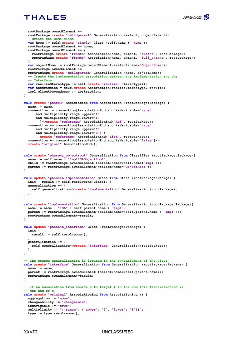
APPENDICES
rootPackage.ownedElement += rootPackage.create "childparent" Generalization (extent, objectExtent); --Create the Home class var home := self.create "simple" Class (self.name + "Home"); rootPackage.ownedElement += home; rootPackage.ownedElement += { rootPackage.create "fromto" Association(home, extent, "extent", rootPackage); rootPackage.create "fromto" Association(home, extent, "full_extent", rootPackage); }; var objectHome := rootPackage.ownedElement->select(name="ObjectHome"); rootPackage.ownedElement += rootPackage.create "childparent" Generalization (home, objectHome); -- Create the implementation association between the Implementation and the -- Interface var realizeStereotype := self.create "realize" Stereotype(); var abstraction = self.create Abstraction(realizeStereotype, result); impl.clientDependency := abstraction; } rule create "phase3" Association from Association (rootPackage:Package) { name := name; connection := connection[AssociationEnd and isNavigable="true" and multiplicity.range.upper="1" and multiplicity.range.lower="1" ]->create "reference" AssociationEnd("Ref", rootPackage); connection += connection[AssociationEnd and isNavigable="true" and multiplicity.range.upper="*" and multiplicity.range.lower="0"]-> create "reference" AssociationEnd("List", rootPackage); connection += connection[AssociationEnd and isNavigable="false"]-> create "original" AssociationEnd(); } rule create "phase4a_objectroot" Generalization from Classifier (rootPackage:Package){ name := self.name + "ImplISAObjectRoot"; child := rootPackage.ownedElement->select(name=(self.name+"Impl")); parent := rootPackage.ownedElement->select(name="ObjectRoot"); } rule update "phase4b_implementation" Class from Class (rootPackage:Packge) { init { result := self.resolveone(Class); } generalization += { self.generalization->create "implementation" Generalization(rootPackage); }; } rule create "implementation" Generalization from Generalization(rootPackage:Package){ name := name + "ISA" + self.parent.name + "Impl"; parent := rootPackage.ownedElement->select(name=(self.parent.name + "Impl")); rootPackage.ownedElement+=result; } rule update "phase4b_interface" Class (rootPackage:Package) { init { result := self.resolveone(); } generalization += { self.generalization->create "interface" Generalization(rootPackage); }; } -- The source generalization is located in the ownedElement of the Class rule create "interface" Generalization from Generalization (rootPackage:Package) { name := name; parent := rootPackage.ownedElement->select(name=(self.parent.name)); rootPackage.ownedElement+=result; } -- If an association from source s to target t in the PSM this AssociationEnd is -- the end of s. rule create "original" AssociationEnd from AssociationEnd () { aggregation := "none"; changeability := "changeable"; isNavigable := "true"; multiplicity := "{'range': {'upper': '1', 'lower': '1'}}"; type := type.resolveone();
UNCLASSIFIED XXVIII

APPENDICES
} -- If an association from source s to target t in the PSM this AssociationEnd is -- the end of t. This one is not pointing to the class directly, but to it's -- reference class. The pattern is placed after the name. For example, it can be -- "Ref" of "List" rule create "reference" AssociationEnd from AssociationEnd(pattern:String, rootPackage:Package) { aggregation := "none"; changeability := "changeable"; isNavigable := "false"; var n := type.resolveone().name + pattern; type := rootPackage.ownedElement->select(name=n); } -- An abstraction is used to implement a realize association from a class -- to an interface rule create Abstraction from Package(s:Stereotype, i:Interface) { stereotype := s; supplier := i; } -- Realize stereotype is used to implement a realize relation between a class -- and an interface rule create "realize" Stereotype from Package() { baseClass := "Classifier"; icon := "realize"; name := "realize"; } -- Create a generalization between the child chld and the parent prnt that are -- given as parameters rule create "childparent" Generalization from Package (chld:Class, prnt:Class) { name := chld.name + "ISA" + prnt.at(0).name; parent := prnt; chld.generalization := result; } -- Create an association from class "fr" to class "to" with name "n" rule create "fromto" Association from Package (fr:Class, to:Class, n:String, rootPackage:Package) { name := n; connection := { rootPackage.create "from" AssociationEnd(fr); rootPackage.create "to" AssociationEnd(to); }; } -- "from" and "to" inherit from this base rule. rule create "base" AssociationEnd from Package (c:Class) { aggregation := "none"; changeability := "changeable"; type := c; } rule create "from" AssociationEnd from Package (c:Class) inherits "base" AssociationEnd{ isNavigable := "true"; } rule create "to" AssociationEnd from Package (c:Class) inherits "base" AssociationEnd { isNavigable := "false"; multiplicity := "{'range': {'upper': '1', 'lower': '1'}}"; aggregation := "composite"; } -- Create class with name set to "n" rule create "simple" Class (n:String) { name := n; }
UNCLASSIFIED XXIX

APPENDICES
UNCLASSIFIED XXX

APPENDICES
Appendix F Univers@lis Scripts
Univers@lis can be used with the command line. To compile and execute transformations, the following scripts were used: #!/bin/tcsh ECHO Creating the program \'Transform\' in the project \'qvt\' /home/di634/univ-3.0/univ-soft/tools/buildProgram.py 'transform' 'qvt' '/cygdrive/c/Documents and Settings/di634/Desktop/xml/transform.trl' 'YP' 'UML=oad.uml13' 'transformator' 'trl' '' #!/bin/tcsh ECHO Executing transform program set before=`date +%s` /usr/bin/python /home/di634/univ-3.0/univ-proj-qvt/programs/transform/transform.py qvt.umlbase:/e qvt.umlbase:/t M set after=`date +%s` @ result=$after - $before ECHO which took $result seconds
To import a model into the repository, the following script was used. #!/bin/tcsh ECHO Importing \'output.xml\' into the project \'qvt\' /home/di634/univ-3.0/univ-soft/python/bin/importFile.py qvt.umlbase '/cygdrive/c/Documents and Settings/di634/Desktop/xml/output.xml' '/e' 'xmi' '' '' 'admin'
UNCLASSIFIED XXXI

APPENDICES
UNCLASSIFIED XXXII

APPENDICES
Appendix G PIM-to-PSM transformation scenarios
In the orientation phase of this assignment the existence of a TRL compiler was unknown. The first intention was to develop a compiler. With the compiler TRL programs could be written and compiled to evaluate the language. In order to execute the transformations, related technologies were observed, resulting in a set of possible transformation approaches. Each approach was represented as a distinct scenario. As soon as the existence of the TRL compiler became clear, the scope of the assignment changed from the development of a compiler to evaluation of TRL. Therefore, the scenarios in this paragraph do not make sense for the current assignment anymore. The reason they are still in the document is that the several scenarios give an overview of possible approaches for model transformations. As stated before, this thesis focuses on the transformation from PIM to PSM and not on the complete transformation from PIM, CEM, DOM and mappings to the complete application. To execute the PIM-to-PSM transformation, several approaches can be identified. This paragraph describes some of the possible approaches. For every approach, positive and negative properties will be addressed. One must keep in mind that the goal of the process is the execution of a transformation that transforms PIM UML models into PSM UML models. The overall picture of a transformation should look like Figure 13 Transformations on page 29.
G.1 Scenar io 1 : Express t rans format ion d i re c t l y i n too l
Transformations can be simply programmed in a UML modeling tool, for example using the J language for UML/Objecteering [50]. Transformations on UML models can then be executed directly in the Objecteering software. Because the tool provides facilities for the visualization of the source and the target models, it can be used for demonstration purposes for transformations. Because the J language is a proprietary language only used by Objecteering, this approach definitely is tool-dependent and cannot easily be ported to other tools.
UML/Objecteering
UML/Objecteering
PIM (UML)PIM (UML)
Transformation (J)
Transformation (J)
PSM (UML)PSM (UML)transformtransform
Figure 77 Scenario 1
The picture shows that the transformation process has two inputs, a transformation expressed in J and an UML model. The result of the transformation is a PSM UML model. All the artifacts and processes are within the Objecteering tool. For other modeling environments similar techniques are available [21][23].
UNCLASSIFIED XXXIII

APPENDICES
G.2 Scenar io 2 : Use TRL d i rec t l y In paragraph 6.1.4 the TRL compiler was described. The compiler can generate TRL programs. Generated programs can be run within the accompanied model repository, Univers@lis. Transformations written in TRL can thus be executed and target models can be created from source models. This process and the artifacts involved are shown below in Figure 78.
TRL compilerTRL compiler
Univers@lisUnivers@lis
PIM(internal representation)
PIM(internal representation)
Transformation (TRL)
Transformation (TRL)
compilecompile
Transformation(Python)
Transformation(Python)
transformtransform PSM(internal representation)
PSM(internal representation)
Figure 78 Scenario 2
The figure shows two processes. The compilation generates Python code from the transformation expressed in TRL. The compilation takes place in the TRL compiler. Within Unvers@lis the Python code executes and performs the transformation on the models in the repository. To use this approach with UML models, several steps must be performed. The user creates models in an UML modeler. The model must be exported from the modeler and imported into the model repository. In the repository the transformation can be executed. Again, The model can be exported and then imported back into the modeler. These steps could be automated using some kind of scripting.
Univers@lisUnivers@lis
UML toolUML toolTRL compilerTRL compilerUML toolUML tool
PIM(internal representation)
PIM(internal representation)
Transformation (TRL)
Transformation (TRL)
compilecompile
Transformation(Python)
Transformation(Python)
transformtransform PSM(internal representation)
PSM(internal representation)
PIM(UML)PIM
(UML)
PIM(XMI XML)
PIM(XMI XML)
exportexport
importimport
PSM(UML)PSM
(UML)
PSM(XMI XML)
PSM(XMI XML)
exportexport
importimport
Figure 79 Scenario 2 (detailed)
Figure 79 shows the steps needed to perform a transformation.
G.3 Scenar io 3 : Use XSLT XSLT can be used to make transformations to XML files directly. A UML modeler is used to create a model. The model is exported to an XMI XML file. The XML is transformed directly into the PSM XML file. The tool can now import the result.
UNCLASSIFIED XXXIV

APPENDICES
XSLTengineXSLTengine
PIM(XMI XML)
PIM(XMI XML)
Translation(XSL)
Translation(XSL)
XSLTXSLT PSM(XMI XML)
PSM(XMI XML)
UML ToolUML ToolPIM
(UML)PIM
(UML)
exportexport
UML ToolUML ToolPSM
(UML)PSM
(UML)
importimport
Figure 80 Scenario 3
G.4 Scenar io 4 : Own Imp lementat ion that generates J
The AST of the TRL source file can be transformed into J code directly using any programming language that can handle XMI. For example Java with Java Metadata Interchange (JMI) can be used to import the XMI file and then a J source file can be constructed from the AST expressed in a Java object structure. This approach is similar to scenario 3, but uses a generic programming language, instead of the dedicated UML transformation language XSLT.
Javaenvironment
Javaenvironment
TRL compilerTRL compiler
AST(XMI XML)
AST(XMI XML)
Transformation (TRL)
Transformation (TRL)
AST(internal representation)
AST(internal representation)
parseparse
exportexport Translation(Java)
Translation(Java)
executeexecute Transformation(J)
Transformation(J)
Figure 81 Scenario 4
G.5 Scenar io 5 : Use TRL to t rans fo rm TRL to J As TRL is a transformation language that can be executed in the Univers@lis model repository, TRL could be used to describe the transformation from TRL to J. The overall picture of this process is a combination of some of the pictures of the former scenarios.
UNCLASSIFIED XXXV

APPENDICES
Univers@lisUnivers@lis
TRLcompiler
TRLcompilerTRL
compilerTRL
compilerTransformation
(TRL)Transformation
(TRL)
TRL AST(internal representation)
TRL AST(internal representation)
ParseParse
Translation (TRL)
Translation (TRL)
Translation(Python)
Translation(Python)
compilecompile
translatetranslate J AST(XMI XML)
J AST(XMI XML)
AST(XMI XML)
AST(XMI XML)
exportexport
Figure 82 Scenario 5
G.6 The used approach Of course the second scenario was used in the case study, because only in this scenario TRL is involved. Using this approach, TRL can be used and evaluated. In the first phase of the project, the existence of a TRL compiler was unknown to us. Therefore, the focus was on the interpretation and execution of TRL. The scenarios were created to explore the possibilities of transformation execution. Because it became clear that a TRL compiler was available, the project focused on the properties of TRL instead of the execution of TRL.
UNCLASSIFIED XXXVI

APPENDICES
Appendix H Java and TRL comparison
This appendix shows the differences and the similarities of several constructs. The pieces of TRL code are taken from Appendix E, the java code is taken from the implementation that was developed in the MIRROR project. TRL can filter elements from a set and call a role on every element in one single statement. TRL: self.ownedElement[Association]->create "phase3" Association (result);
Java: for(final Iterator iter = pimModel.getOwnedTypes().iterator(); iter.hasNext();){
final Type ownedType = (Type) iter.next();
if (ownedType instanceof Association)
caseAssociation ((Association) ownedType);
}
The creation of model elements in TRL has always the same structure. In Java several approaches can be used. In this case a factory is used that creates new elements in the model.
TRL: ownedElement := self.create "simple" Class ("ObjectRoot")
Java: Factory.newClass(psmModel, “ObjectRoot”);
Every model element that is created using TRL needs a separate rule. Thus, for an association between two classes, three rules must be specified. In Java these elements can all be grouped into one method. TRL: -- Create an association from class "fr" to class "to" with name "n" rule create "fromto" Association from Package (fr:Class, to:Class, n:String, rootPackage:Package) { name := n; connection := { rootPackage.create "from" AssociationEnd(fr); rootPackage.create "to" AssociationEnd(to); }; } rule create "from" AssociationEnd from Package (c:Class) inherits "base" AssociationEnd{ isNavigable := "true"; } rule create "to" AssociationEnd from Package (c:Class) inherits "base" AssociationEnd { isNavigable := "false"; multiplicity := "{'range': {'upper': '1', 'lower': '1'}}"; aggregation := "composite"; }
UNCLASSIFIED XXXVII

APPENDICES
Java: private Association caseAssociation (Association pimAssociation) {
Association psmAssociation = (Association) itemMap.get(pimAssociation); if (psmAssociation != null) return psmAssociation; psmAssociation = factory.newAssociation(psmModel, pimAssociation.getName()); for (final Iterator iter=pimAssociation.getMemberEnd().iterator();iter.hasNext();){ final Property pimEnd = (Property) iter.next(); final Property psmEnd = (Property) newEnd(pimEnd); if (pimEnd.getOwningAssociation()==null) psmAssociation.getMemberEnds().add(psmEnd); else psmAssociation.getOwnedEnds().add(psmEnd); } itemMap.put(pimAssociation, psmAssociation); return psmAssociation;
}
UNCLASSIFIED XXXVIII
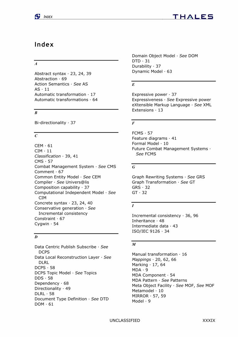
INDEX
Index
A
Abstract syntax · 23, 24, 39 Abstraction · 69 Action Semantics · See AS AS · 11 Automatic transformation · 17 Automatic transformations · 64
B
Bi-directionality · 37
C
CEM · 61 CIM · 11 Classification · 39, 41 CMS · 57 Combat Management System · See CMS Comment · 67 Common Entity Model · See CEM Compiler · See Univers@lis Composition capability · 37 Computational Independent Model · See
CIM Concrete syntax · 23, 24, 40 Conservative generation · See
Incremental consistency Constraint · 67 Cygwin · 54
D
Data Centric Publish Subscribe · See DCPS
Data Local Reconstruction Layer · See DLRL
DCPS · 58 DCPS Topic Model · See Topics DDS · 58 Dependency · 68 Directionality · 49 DLRL · 58 Document Type Definition · See DTD DOM · 61
Domain Object Model · See DOM DTD · 31 Durability · 37 Dynamic Model · 63
E
Expressive power · 37 Expressiveness · See Expressive power eXtensible Markup Language · See XML Extensions · 13
F
FCMS · 57 Feature diagrams · 41 Formal Model · 10 Future Combat Management Systems ·
See FCMS
G
Graph Rewriting Systems · See GRS Graph Transformation · See GT GRS · 32 GT · 32
I
Incremental consistency · 36, 96 Inheritance · 48 Intermediate data · 43 ISO/IEC 9126 · 34
M
Manual transformation · 16 Mappings · 20, 62, 66 Marking · 17, 64 MDA · 9 MDA Component · 54 MDA Pattern · See Patterns Meta Object Facility · See MOF, See MOF Metamodel · 10 MIRROR · 57, 59 Model · 9
UNCLASSIFIED XXXIX

INDEX
Model Driven Architecture · See MDA Model marking · See Marking Model Transformations · See
Transformations Model types · 39 MOF · 14 MOF based extensions · See extensions
O
Object Constraint Language · See OCL Objecteering/UML · 54 OCL · 15 Order · 97
P
Parameters · 44 Patterns · 16, 33, 64 PIM · 11, 60 Platform · 10 Platform Independent Model · See PIM Platform Specific Model · See PSM Portability · 37 Process · 17 Product quality · See Quality Profile · See Extensions Profile Builder · See Objecteering/UML Profile-based extensions · See
extensions Profiles · 17, 55, 64 PSM · 11, 60
Q
Quality · 34 Query / Views / Transformations · See
QVT QVT · 17
R
Readability · 37 Relationship · 67 RFP · 18 Rule execution order · See Order Rule inheritance · 48
Rule Scheduling · 46
S
Schema · See XML Schema SPLICE · 58 Static Model · 63
T
TACTICOS · 57 TE · 57 Thales Research and Technology · See
TRT Threat Evaluation · See TE Topic Model · See Topics Topics · 61 Traceability · 36, 48, 96 Transformation Rule Language · See
TRL, See TRL Transformations · 16, 29, 60, 64 TRL · 39 TRL compiler · See Univers@lis TRT · 4 Tuneability · 35
U
UML · 11, 67 UML Modeler · 54 UML Profile Builder · 54 Unified Modeling Language · See UML Unit inheritance · 48 Univers@lis · 51
V
Viewpoints · 11, 16
X
XMI · 31 XML · 30 XML Meta data Interchange · See XMI XML Schema · 31
UNCLASSIFIED XL

INDEX
UNCLASSIFIED XLI