specworld.inspecworld.in/wp-content/uploads/2019/03/unit-i.docx · web viewhadoop offers a...
TRANSCRIPT
UNIT 1SYSTEMS MODELING, CLUSTERING, AND VIRTUALIZATION
1.1 Distributed System Models and Enabling Technologies1.1.1 Scalable Computing Over the Internet
Over the past 10 years, computing technology has undergone a series of platform and environment changes. 1.1.1 .1The Age of Internet Computing
Billions of people use the Internet every day. As a result, supercomputer sites and large data centers must provide high-performance computing services to huge numbers of Internet users concurrently. Because of this high demand, the Linpack Benchmark for high-performance computing (HPC) applications is no longer optimal for measuring system performance. The emergence of computing clouds instead demands high-throughput computing (HTC) systems built with parallel and distributed computing technologies. The Platform Evolution
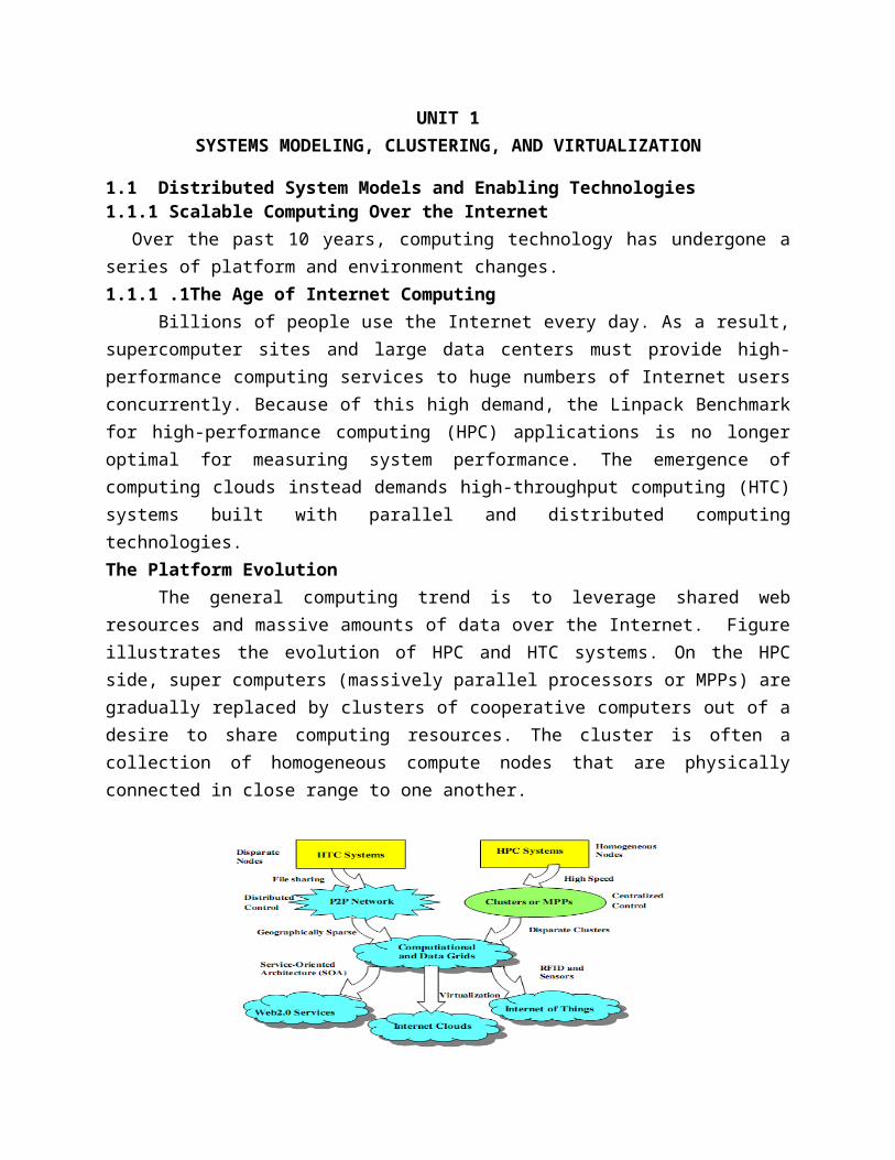
The general computing trend is to leverage shared web resources and massive amounts of data over the Internet. Figure illustrates the evolution of HPC and HTC systems. On the HPC side, super computers (massively parallel processors or MPPs) are gradually replaced by clusters of cooperative computers out of a desire to share computing resources. The cluster is often a collection of homogeneous compute nodes that are physically connected in close range to one another.
High-Performance ComputingFor many years, HPC systems emphasize the raw speed performance. The speed of HPC
systems has increased from Gflops in the early 1990s to now Pflops in 2010. This improvement was driven mainly by the demands from scientific, engineering, and manufacturing communities. High-Throughput Computing
This HTC paradigm pays more attention to high-flux computing. The main application for high-flux computing is in Internet searches and web services by millions or more users simultaneously. The performance goal thus shifts to measure high throughput or the number of tasks completed per unit of time.
Three New Computing ParadigmsAdvances in virtualization make it possible to see the growth of Internet clouds as a new
computing paradigm. The maturity of radio-frequency identification (RFID), Global Positioning System (GPS), and sensor technologies has triggered the development of the Internet of Things (IoT).Computing Paradigm Distinctions• Centralized computing: This is a computing paradigm by which all computer resources are centralized in one physical system. All resources (processors, memory, and storage) are fully shared and tightly coupled within one integrated OS. Many data centers and supercomputers are centralized systems, but they are used in parallel, distributed, and cloud computing applications.• Parallel computing: In parallel computing, all processors are either tightly coupled with centralized shared memory or loosely coupled with distributed memory. A computer system capable of parallel computing is commonly known as a parallel computer. Programs running in a parallel computer are called parallel programs. The process of writing parallel programs is often referred to as parallel programming• Distributed computing: A distributed system consists of multiple autonomous computers, each having its own private memory, communicating through a computer network. Information exchange in a distributed system is accomplished through message passing. A computer program that runs in a distributed system is known as a distributed program. The process of writing distributed programs is referred to as distributed programming.• Cloud computing: The cloud applies parallel or distributed computing, or both. Clouds can be built with physical or virtualized resources over large data centers that are centralized or distributed. Distributed System Families
Since the mid-1990s, technologies for building P2P networks and networks of clusters have been consolidated into many national projects designed to establish wide area computing infrastructures, known as computational grids or data grids.
The largest computational grid connects up to hundreds of server clusters. A typical P2P network may involve millions of client machines working simultaneously.
Both HPC and HTC systems emphasize parallelism and distributed computing. Future HPC and HTC systems must be able to satisfy this huge demand in computing power in terms of throughput, efficiency, scalability, and reliability. Meeting these goals requires yielding the following design objectives:• Efficiency measures the utilization rate of resources in an execution model by exploiting massive parallelism in HPC. For HTC, efficiency is more closely related to job throughput, data access, storage, and power efficiency• Dependability measures the reliability and self-management from the chip to the system and application levels. • Adaptation in the programming model measures the ability to support billions of job requests over massive data sets and virtualized cloud resources under various workload and service models.
• Flexibility in application deployment measures the ability of distributed systems to run well in both HPC (science and engineering) and HTC (business) applications.1.1.1.2 Scalable Computing Trends and New Paradigms Degrees of Parallelism
Fifty years ago, when hardware was bulky and expensive, most computers were designed in a bit-serial fashion. In this scenario, bit-level parallelism (BLP) converts bit-serial processing to word-level processing gradually. Over the years, users graduated from 4-bit microprocessors to 4-,8-, 31-, and 14-bit CPUs. This led us to the next wave of improvement, known as instruction-level parallelism (ILP), in which the processor executes multiple instructions simultaneously rather than only one instruction at a time. Data level parallelism (DLP) was made popular through SIMD (single instruction, multiple data) and vector machines using vector or array types of instructions. DLP requires even more hardware support and compiler assistance to work properly. Ever since the introduction of multicore processors and chip multiprocessors (CMPs), we have been exploring task-level parallelism (TLP).A modern processor explores all of the aforementioned parallelism types. In fact, BLP, ILP, and DLP are well supported by advances in hardware and compilers. However, TLP is far from being very successful due to difficulty in programming and compilation of code for efficient execution on multicore CMPs. As we move from parallel processing to distribute processing, we will see an increase in computing granularity to job-level parallelism (JLP). It is fair to say that coarse-grain parallelism is built on top of fine-grain parallelism.Innovative Applications
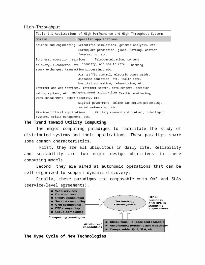
Both HPC and HTC systems desire transparency in many application aspects. For example, data access, resource allocation, process location, concurrency in execution, job replication, and failure recovery should be made transparent to both users and system management. Table 1.1 highlights a few key applications that have driven the development of parallel and distributed systems over Applications of High-Performance and High-Throughput
Table 1.1 Applications of High-Performance and High-Throughput SystemsDomain Specific ApplicationsScience and engineering Scientific simulations, genomic analysis, etc.
Earthquake prediction, global warming, weather forecasting, etc.
Business, education, services Telecommunication, content delivery, e-commerce, etc. industry, and health care Banking, stock exchanges, transaction processing, etc.
Air traffic control, electric power grids, distance education, etc. Health care, hospital automation, telemedicine, etc.
Internet and web services, Internet search, data centers, decision-making systems, etc. and government applications Traffic monitoring, worm containment, cyber security, etc.
Digital government, online tax return processing, social networking, etc.
Mission-critical applications Military command and control, intelligent systems, crisis management, etc.
The Trend toward Utility ComputingThe major computing paradigms to facilitate the study of distributed systems and their
applications. These paradigms share some common characteristics. First, they are all ubiquitous in daily life. Reliability and scalability are two major design
objectives in these computing models. Second, they are aimed at autonomic operations that can be self-organized to support
dynamic discovery.Finally, these paradigms are composable with QoS and SLAs (service-level agreements).
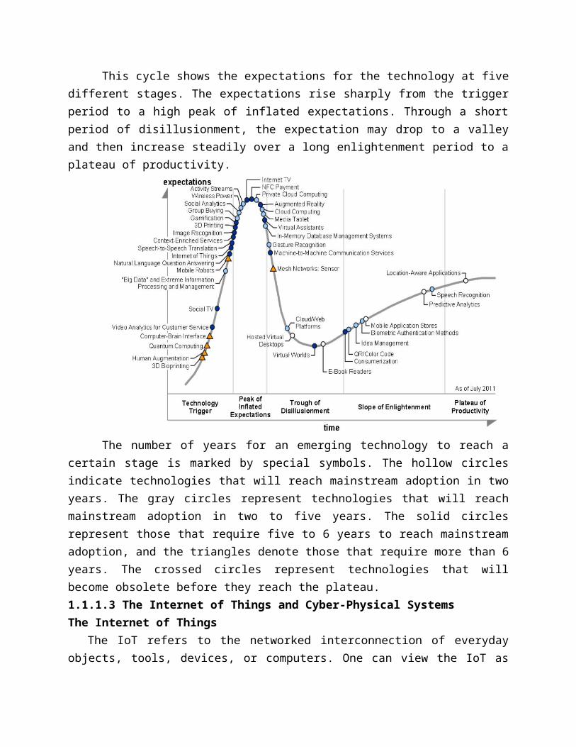
The Hype Cycle of New TechnologiesThis cycle shows the expectations for the technology at five different stages. The
expectations rise sharply from the trigger period to a high peak of inflated expectations. Through a short period of disillusionment, the expectation may drop to a valley and then increase steadily over a long enlightenment period to a plateau of productivity.
The number of years for an emerging technology to reach a certain stage is marked by special symbols. The hollow circles indicate technologies that will reach mainstream adoption in
two years. The gray circles represent technologies that will reach mainstream adoption in two to five years. The solid circles represent those that require five to 6 years to reach mainstream adoption, and the triangles denote those that require more than 6 years. The crossed circles represent technologies that will become obsolete before they reach the plateau.1.1.1.3 The Internet of Things and Cyber-Physical SystemsThe Internet of Things
The IoT refers to the networked interconnection of everyday objects, tools, devices, or computers. One can view the IoT as wireless networks of sensors that interconnect all things in our daily life. These things can be large or small and they vary with respect to time and place.In the IoT era, all objects and devices are instrumented, interconnected, and interacted with each other intelligently. This communication can be made between people and things or among the things themselves. Three communication patterns co-exist: namely H2H (human-to-human), H2T (human-to thing), and T2T (thing-to-thing). Here things include machines such as PCs and mobile phones. The idea here is to connect things (including human and machine objects) at any time and any place intelligently with low cost. Cyber-Physical Systems
A cyber-physical system (CPS) is the result of interaction between computational processes and the physical world. A CPS integrates “cyber” (heterogeneous, asynchronous) with “physical” (concurrent and information-dense) objects. A CPS merges the “3C” technologies of computation, communication, and control into an intelligent closed feedback system between the physical world and the information world, a concept which is actively explored in the United States. 1.1.2 Technologies for Network-Based Systems1.1.2.1 Multicore CPUs and Multithreading Technologies
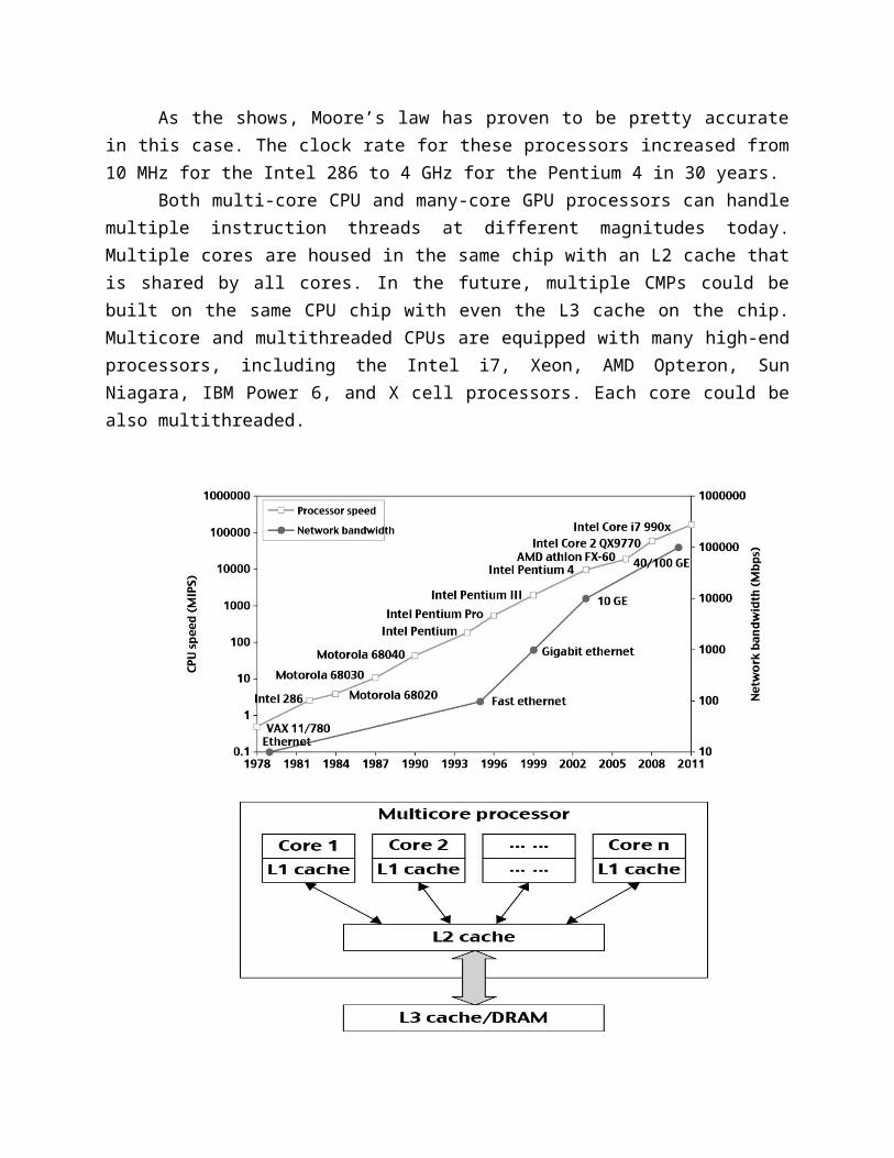
Consider the growth of component and network technologies over the past 30 years. They are crucial to the development of HPC and HTC systems. The unit GE refers to 1 Gbps Ethernet bandwidth.Advances in CPU Processors
Today, advanced CPUs or microprocessor chips assume a multicore architecture with dual, quad, six, or more processing cores. These processors exploit parallelism at ILP and TLP levels. We see growth from 1 MIPS for the VAX 780 in 1978 to 1,800 MIPS for the Intel Pentium4 in 2002, up to a 22,000 MIPS peak for the Sun Niagara 2 in 2008.
As the shows, Moore’s law has proven to be pretty accurate in this case. The clock rate for these processors increased from 10 MHz for the Intel 286 to 4 GHz for the Pentium 4 in 30 years.
Both multi-core CPU and many-core GPU processors can handle multiple instruction threads at different magnitudes today. Multiple cores are housed in the same chip with an L2 cache that is shared by all cores. In the future, multiple CMPs could be built on the same CPU chip with even the L3 cache on the chip. Multicore and multithreaded CPUs are equipped with many high-end processors, including the Intel i7, Xeon, AMD Opteron, Sun Niagara, IBM
Power 6, and X cell processors. Each core could be also multithreaded.
Multicore CPU and Many-Core GPU ArchitecturesMulticore CPUs may increase from the tens of cores to hundreds or more in the future.
But the CPU has reached its limit in terms of exploiting massive DLP due to the aforementioned memory wall problem. This has triggered the development of many-core GPUs with hundreds or more thin cores. Both IA-32 and IA-64 instruction set architectures are built into commercial CPUs. Now, x-41 processors have been extended to serve HPC and HTC systems in some high-end server processors.
Many RISC processors have been replaced with multicore x-41 processors and many-core GPUs in the Top 5000 systems. This trend indicates that x-41 upgrades will dominate in data centers and supercomputers. The GPU also has been applied in large clusters to build supercomputers in MPPs. In the future, the processor industry is also keen to develop asymmetric or heterogeneous chip multiprocessors that can house both fat CPU cores and thin GPU cores on the same chip.Multithreading Technology
Consider in figure the dispatch of five independent threads of instructions to four pipelined data paths (functional units) in each of the following five processor categories, from left to right:
1. A four-issue superscalar processor2. A fine-grain multithreaded processor3. A coarse-grain multithreaded processor4. A two-core CMP and5. A simultaneous multithreaded (SMT) processor.
The superscalar processor is single-threaded with four functional units. Each of the three multithreaded processors is four-way multithreaded over four functional data paths. Only instructions from the same thread are executed in a superscalar processor.
Fine-grain multithreading switches the execution of instructions from different threads per cycle.
Course-grain multithreading executes many instructions from the same thread for quite a few cycles before switching to another thread.
In the dual-core processor, assume two processing cores, each a single-threaded two-way superscalar processor. Instructions from different threads are distinguished by specific shading patterns for instructions from five independent threads. Typical instruction scheduling patterns are shown here. The multicore CMP executes instructions from different threads completely.
The SMT allows simultaneous scheduling of instructions from different threads in the same cycle. These execution patterns closely mimic an ordinary program. The blank squares correspond to no available instructions for an instruction data path at a particular processor cycle. More blank cells imply lower scheduling efficiency.
1.1.2.2 GPU Computing to Exascale and BeyondA GPU is a graphics coprocessor or accelerator mounted on a computer’s graphics card
or video card. A GPU offloads the CPU from tedious graphics tasks in video editing applications. The world’s first GPU, the GeForce 256, was marketed by NVIDIA in 1999. Lately, parallel GPUs or GPU clusters have been garnering a lot of attention against the use of CPUs with limited parallelism. General-purpose computing on GPUs, known as GPGPUs, have appeared in the HPC field. NVIDIA’s CUDA model was for HPC using GPGPUsHow GPUs Work
Early GPUs functioned as coprocessors attached to the CPU. Modern GPUs are not restricted to accelerated graphics or video coding. They are used in HPC systems to power supercomputers with massive parallelism at multicore and multithreading levels. GPUs are designed to handle large numbers of floating-point operations in parallel. In a way, the GPU offloads the CPU from all data-intensive calculations, not just those that are related to video processing. Conventional GPUs are widely used in mobile phones, game consoles, embedded systems, PCs, and servers. The NVIDIA CUDA Tesla or Fermi is used in GPU clusters or in HPC systems for parallel processing of massive floating-pointing data.GPU Programming Model
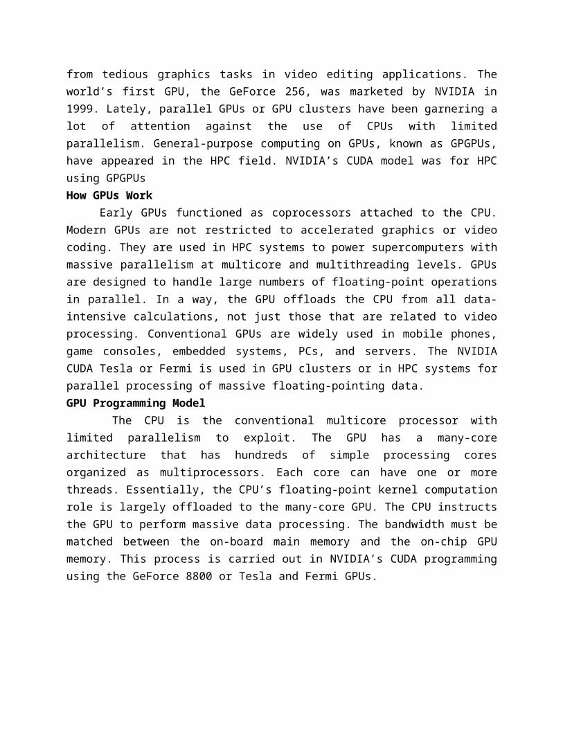
The CPU is the conventional multicore processor with limited parallelism to exploit. The GPU has a many-core architecture that has hundreds of simple processing cores organized as multiprocessors. Each core can have one or more threads. Essentially, the CPU’s floating-point kernel computation role is largely offloaded to the many-core GPU. The CPU instructs the GPU to perform massive data processing. The bandwidth must be matched between the on-board main
memory and the on-chip GPU memory. This process is carried out in NVIDIA’s CUDA programming using the GeForce 8800 or Tesla and Fermi GPUs.
Four challenges are identified for exascale computing: (1) energy and power, (2)memory and storage, (3) concurrency and locality, and (4) system resiliency. 1.1.2.3 Memory, Storage, and Wide-Area NetworkingMemory Technology
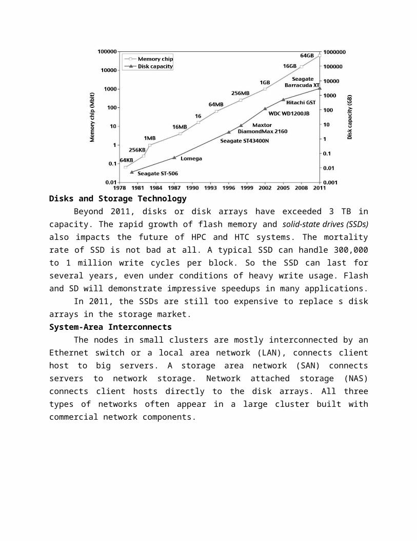
Memory access time did not improve much in the past. In fact, the memory wall problem is getting worse as the processor gets faster. For hard drives, capacity increased from 2500 MB in 1981 to 250 GB in 2004. The Seagate Barracuda XT hard drive reached 3 TB in 2011. This represents an approximately 10x increase in capacity every eight years. The capacity increase of disk arrays will be even greater in the years to come. Faster processor speed and larger memory capacity result in a wider gap between processors and memory. The memory wall may become even worse a problem limiting the CPU performance in the future.
Disks and Storage TechnologyBeyond 2011, disks or disk arrays have exceeded 3 TB in capacity. The rapid growth of
flash memory and solid-state drives (SSDs) also impacts the future of HPC and HTC systems. The mortality rate of SSD is not bad at all. A typical SSD can handle 300,000 to 1 million write cycles per block. So the SSD can last for several years, even under conditions of heavy write usage. Flash and SD will demonstrate impressive speedups in many applications.
In 2011, the SSDs are still too expensive to replace s disk arrays in the storage market.System-Area Interconnects
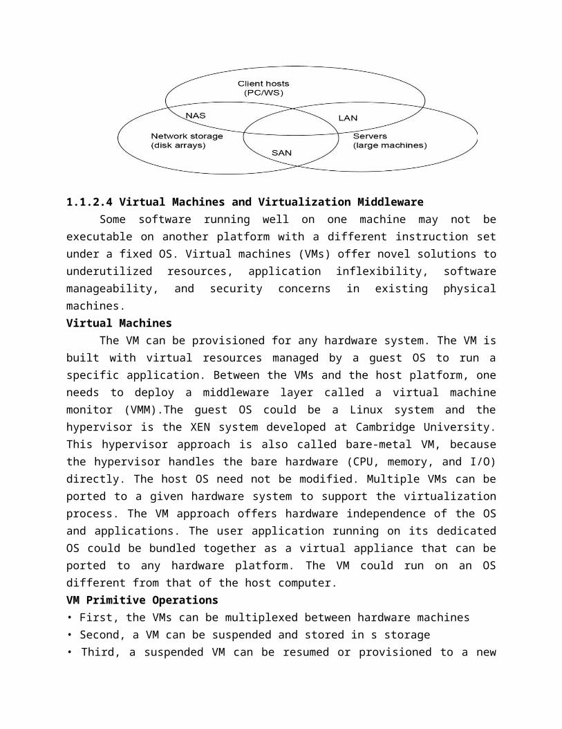
The nodes in small clusters are mostly interconnected by an Ethernet switch or a local area network (LAN), connects client host to big servers. A storage area network (SAN) connects servers to network storage. Network attached storage (NAS) connects client hosts directly to the disk arrays. All three types of networks often appear in a large cluster built with commercial network components.
1.1.2.4 Virtual Machines and Virtualization MiddlewareSome software running well on one machine may not be executable on another platform
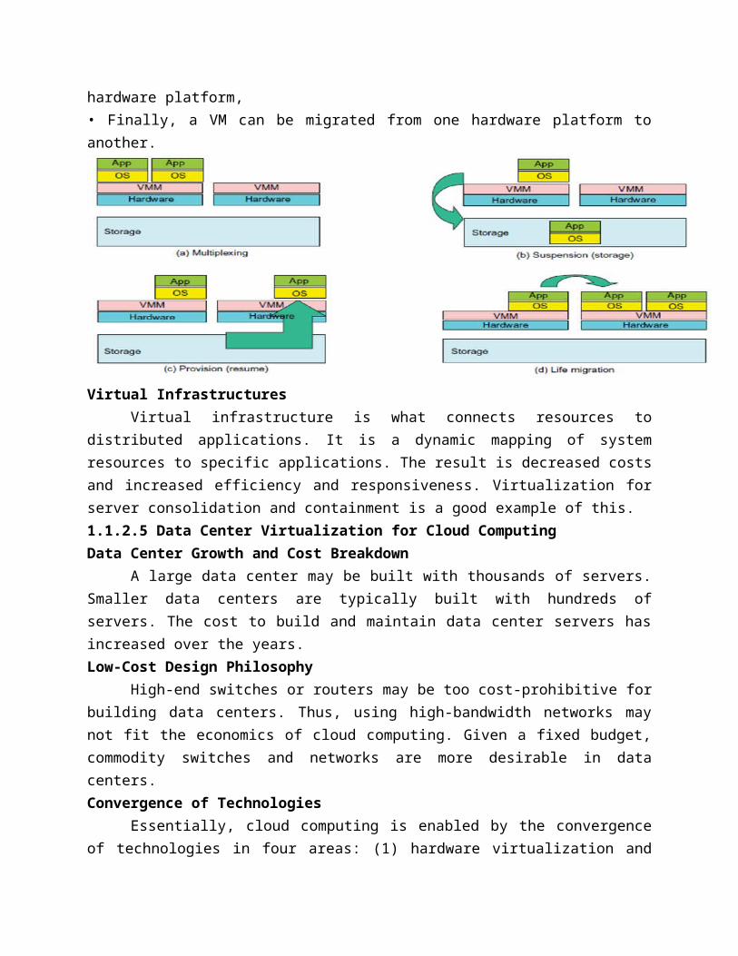
with a different instruction set under a fixed OS. Virtual machines (VMs) offer novel solutions to underutilized resources, application inflexibility, software manageability, and security concerns in existing physical machines. Virtual Machines The VM can be provisioned for any hardware system. The VM is built with virtual resources managed by a guest OS to run a specific application. Between the VMs and the host platform, one needs to deploy a middleware layer called a virtual machine monitor (VMM).The guest OS could be a Linux system and the hypervisor is the XEN system developed at Cambridge University. This hypervisor approach is also called bare-metal VM, because the hypervisor handles the bare hardware (CPU, memory, and I/O) directly. The host OS need not be modified. Multiple VMs can be ported to a given hardware system to support the virtualization process. The VM approach offers hardware independence of the OS and applications. The user application running on its dedicated OS could be bundled together as a virtual appliance that can be ported to any hardware platform. The VM could run on an OS different from that of the host computer.VM Primitive Operations• First, the VMs can be multiplexed between hardware machines• Second, a VM can be suspended and stored in s storage• Third, a suspended VM can be resumed or provisioned to a new hardware platform,
• Finally, a VM can be migrated from one hardware platform to another.
Virtual InfrastructuresVirtual infrastructure is what connects resources to distributed applications. It is a
dynamic mapping of system resources to specific applications. The result is decreased costs and increased efficiency and responsiveness. Virtualization for server consolidation and containment is a good example of this. 1.1.2.5 Data Center Virtualization for Cloud Computing Data Center Growth and Cost Breakdown
A large data center may be built with thousands of servers. Smaller data centers are typically built with hundreds of servers. The cost to build and maintain data center servers has increased over the years. Low-Cost Design Philosophy
High-end switches or routers may be too cost-prohibitive for building data centers. Thus, using high-bandwidth networks may not fit the economics of cloud computing. Given a fixed budget, commodity switches and networks are more desirable in data centers. Convergence of Technologies
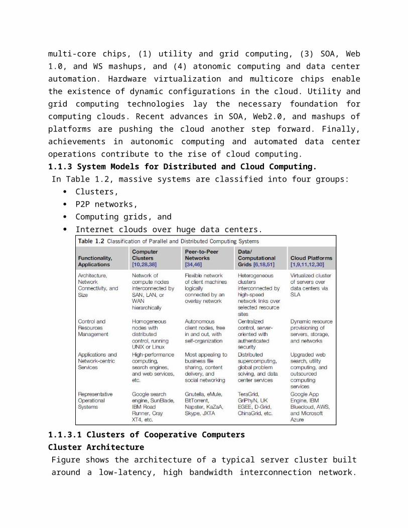
Essentially, cloud computing is enabled by the convergence of technologies in four areas: (1) hardware virtualization and multi-core chips, (1) utility and grid computing, (3) SOA, Web 1.0, and WS mashups, and (4) atonomic computing and data center automation. Hardware virtualization and multicore chips enable the existence of dynamic configurations in the cloud. Utility and grid computing technologies lay the necessary foundation for computing clouds. Recent advances in SOA, Web2.0, and mashups of platforms are pushing the cloud another step forward. Finally, achievements in autonomic computing and automated data center operations contribute to the rise of cloud computing. 1.1.3 System Models for Distributed and Cloud Computing.In Table 1.2, massive systems are classified into four groups:
Clusters, P2P networks, Computing grids, and
Internet clouds over huge data centers.
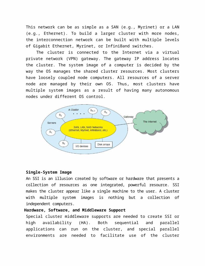
1.1.3.1 Clusters of Cooperative ComputersCluster ArchitectureFigure shows the architecture of a typical server cluster built around a low-latency, high bandwidth interconnection network. This network can be as simple as a SAN (e.g., Myrinet) or a LAN (e.g., Ethernet). To build a larger cluster with more nodes, the interconnection network can be built with multiple levels of Gigabit Ethernet, Myrinet, or InfiniBand switches.
The cluster is connected to the Internet via a virtual private network (VPN) gateway. The gateway IP address locates the cluster. The system image of a computer is decided by the way the OS manages the shared cluster resources. Most clusters have loosely coupled node computers. All resources of a server node are managed by their own OS. Thus, most clusters have multiple system images as a result of having many autonomous nodes under different OS control.
Single-System ImageAn SSI is an illusion created by software or hardware that presents a collection of resources as one integrated, powerful resource. SSI makes the cluster appear like a single machine to the user. A cluster with multiple system images is nothing but a collection of independent computers.
Hardware, Software, and Middleware SupportSpecial cluster middleware supports are needed to create SSI or high availability (HA). Both sequential and parallel applications can run on the cluster, and special parallel environments are needed to facilitate use of the cluster resources.
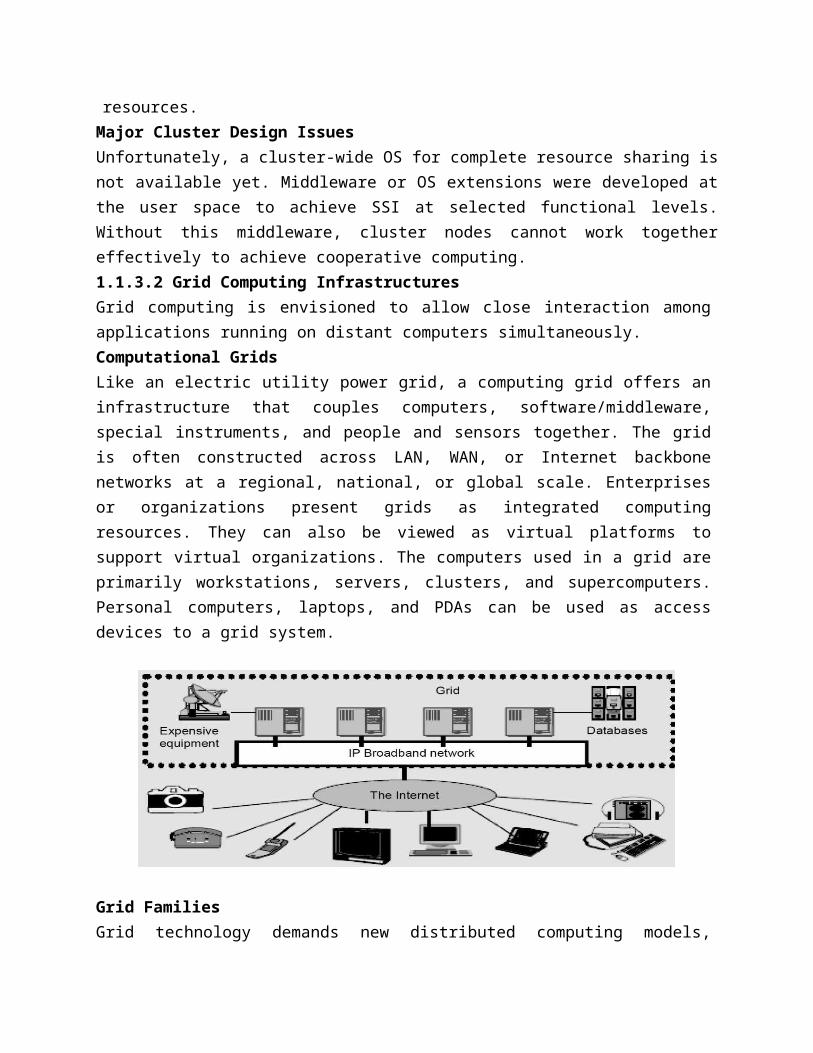
Major Cluster Design IssuesUnfortunately, a cluster-wide OS for complete resource sharing is not available yet. Middleware or OS extensions were developed at the user space to achieve SSI at selected functional levels. Without this middleware, cluster nodes cannot work together effectively to achieve cooperative computing.1.1.3.2 Grid Computing InfrastructuresGrid computing is envisioned to allow close interaction among applications running on distant computers simultaneously.Computational GridsLike an electric utility power grid, a computing grid offers an infrastructure that couples computers, software/middleware, special instruments, and people and sensors together. The grid is often constructed across LAN, WAN, or Internet backbone networks at a regional, national, or global scale. Enterprises or organizations present grids as integrated computing resources. They can also be viewed as virtual platforms to support virtual organizations. The computers used in a grid are primarily workstations, servers, clusters, and supercomputers. Personal computers, laptops, and PDAs can be used as access devices to a grid system.
Grid FamiliesGrid technology demands new distributed computing models, software/middleware support, network protocols, and hardware infrastructures. New grid service providers (GSPs) and new grid applications have emerged rapidly, similar to
the growth of Internet and web services in the past two decades.Grid systems are classified into two categories: computational or data grids and P2P grids.
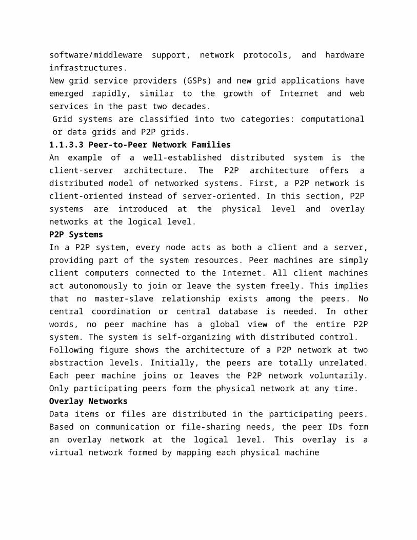
1.1.3.3 Peer-to-Peer Network FamiliesAn example of a well-established distributed system is the client-server architecture. The P2P architecture offers a distributed model of networked systems. First, a P2P network is client-oriented instead of server-oriented. In this section, P2P systems are introduced at the physical level and overlay networks at the logical level.P2P SystemsIn a P2P system, every node acts as both a client and a server, providing part of the system resources. Peer machines are simply client computers connected to the Internet. All client machines act autonomously to join or leave the system freely. This implies that no master-slave relationship exists among the peers. No central coordination or central database is needed. In other words, no peer machine has a global view of the entire P2P system. The system is self-organizing with distributed control.Following figure shows the architecture of a P2P network at two abstraction levels. Initially, the peers are totally unrelated. Each peer machine joins or leaves the P2P network voluntarily. Only participating peers form the physical network at any time.Overlay NetworksData items or files are distributed in the participating peers. Based on communication or file-sharing needs, the peer IDs form an overlay network at the logical level. This overlay is a virtual network formed by mapping each physical machine
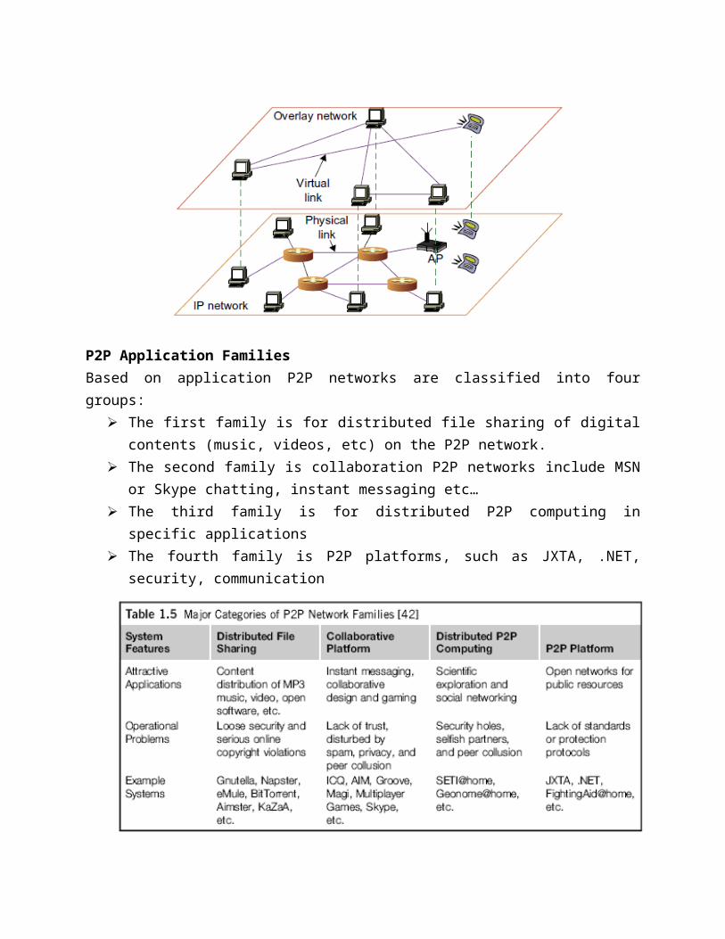
P2P Application FamiliesBased on application P2P networks are classified into four groups:
The first family is for distributed file sharing of digital contents (music, videos, etc) on the P2P network.
The second family is collaboration P2P networks include MSN or Skype chatting, instant messaging etc…
The third family is for distributed P2P computing in specific applications The fourth family is P2P platforms, such as JXTA, .NET, security, communication
P2P Computing ChallengesP2P computing faces three types of heterogeneity problems in hardware, software, and network requirements.
There are too many hardware models and architectures to select from Incompatibility exists between software and the OS Different network connections and protocols make it too complex to apply in real
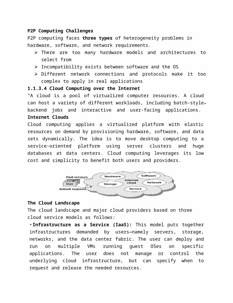
applications1.1.3.4 Cloud Computing over the Internet“A cloud is a pool of virtualized computer resources. A cloud can host a variety of different workloads, including batch-style backend jobs and interactive and user-facing applications.” Internet CloudsCloud computing applies a virtualized platform with elastic resources on demand by provisioning hardware, software, and data sets dynamically. The idea is to move desktop computing to a service-oriented platform using server clusters and huge databases at data centers. Cloud computing leverages its low cost and simplicity to benefit both users and providers.
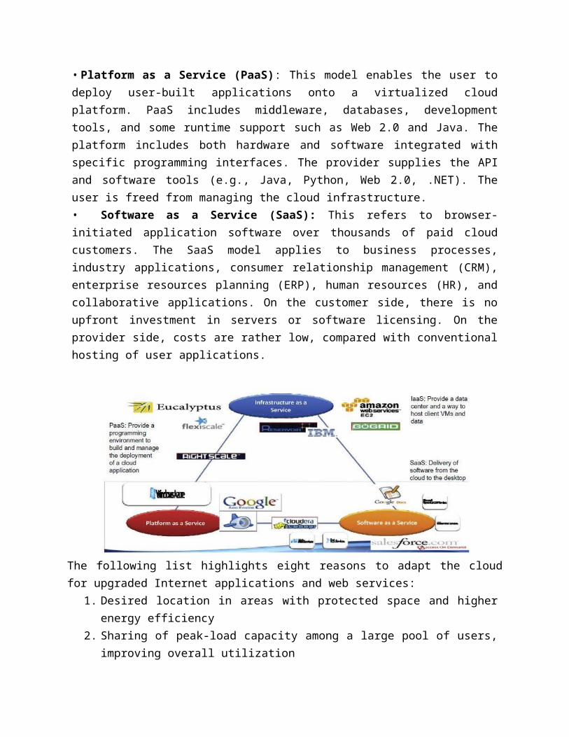
The Cloud LandscapeThe cloud landscape and major cloud providers based on three cloud service models as follows:• Infrastructure as a Service (IaaS): This model puts together infrastructures demanded by
users—namely servers, storage, networks, and the data center fabric. The user can deploy and run on multiple VMs running guest OSes on specific applications. The user does not manage or control the underlying cloud infrastructure, but can specify when to request and release the needed resources.• Platform as a Service (PaaS): This model enables the user to deploy user-built applications onto a virtualized cloud platform. PaaS includes middleware, databases, development tools, and some runtime support such as Web 2.0 and Java. The platform includes both hardware and software integrated with specific programming interfaces. The provider supplies the API and software tools (e.g., Java, Python, Web 2.0, .NET). The user is freed from managing the cloud infrastructure.• Software as a Service (SaaS): This refers to browser-initiated application software over thousands of paid cloud customers. The SaaS model applies to business processes, industry applications, consumer relationship management (CRM), enterprise resources planning (ERP), human resources (HR), and collaborative applications. On the customer side, there is no upfront investment in servers or software licensing. On the provider side, costs are rather low, compared with conventional hosting of user applications.
The following list highlights eight reasons to adapt the cloud for upgraded Internet applications and web services:
1. Desired location in areas with protected space and higher energy efficiency2. Sharing of peak-load capacity among a large pool of users, improving overall utilization3. Separation of infrastructure maintenance duties from domain-specific application
development4. Significant reduction in cloud computing cost, compared with traditional computing
paradigms5. Cloud computing programming and application development6. Service and data discovery and content/service distribution7. Privacy, security, copyright, and reliability issues8. Service agreements, business models, and pricing policies
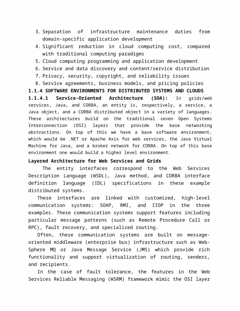
1.1.4 SOFTWARE ENVIRONMENTS FOR DISTRIBUTED SYSTEMS AND CLOUDS1.1.4.1 Service-Oriented Architecture (SOA): In grids/web services, Java, and CORBA, an entity is, respectively, a service, a Java object, and a CORBA distributed object in a variety of languages. These architectures build on the traditional seven Open Systems Interconnection (OSI) layers that provide the base networking abstractions. On top of this we have a base software environment, which would be .NET or Apache Axis for web services, the Java Virtual Machine for Java, and a broker network for CORBA. On top of this base environment one would build a higher level environment.
Layered Architecture for Web Services and GridsThe entity interfaces correspond to the Web Services Description Language (WSDL),
Java method, and CORBA interface definition language (IDL) specifications in these example distributed systems.
These interfaces are linked with customized, high-level communication systems: SOAP, RMI, and IIOP in the three examples. These communication systems support features including particular message patterns (such as Remote Procedure Call or RPC), fault recovery, and specialized routing.
Often, these communication systems are built on message-oriented middleware (enterprise bus) infrastructure such as Web- Sphere MQ or Java Message Service (JMS) which provide rich functionality and support virtualization of routing, senders, and recipients.
In the case of fault tolerance, the features in the Web Services Reliable Messaging (WSRM) framework mimic the OSI layer capability (as in TCP fault tolerance) modified to match the different abstractions (such as messages versus packets, virtualized addressing) at the entity levels.
Security is a critical capability that either uses or re-implements the capabilities seen in concepts such as Internet Protocol Security (IPsec) and secure sockets in the OSI layers.
Entity communication is supported by higher level services for registries, metadata, and management.Web Services and ToolsThe following picture corresponds to two choices of service architecture: web services or REST systems.
Both web services and REST systems have very distinct approaches to building reliable interoperable systems.
In web services, one aims to fully specify all aspects of the service and its environment. This specification is carried with communicated messages using Simple Object Access Protocol (SOAP).
In the REST approach, one adopts simplicity as the universal principal and delegates most of the difficult problems to application software.
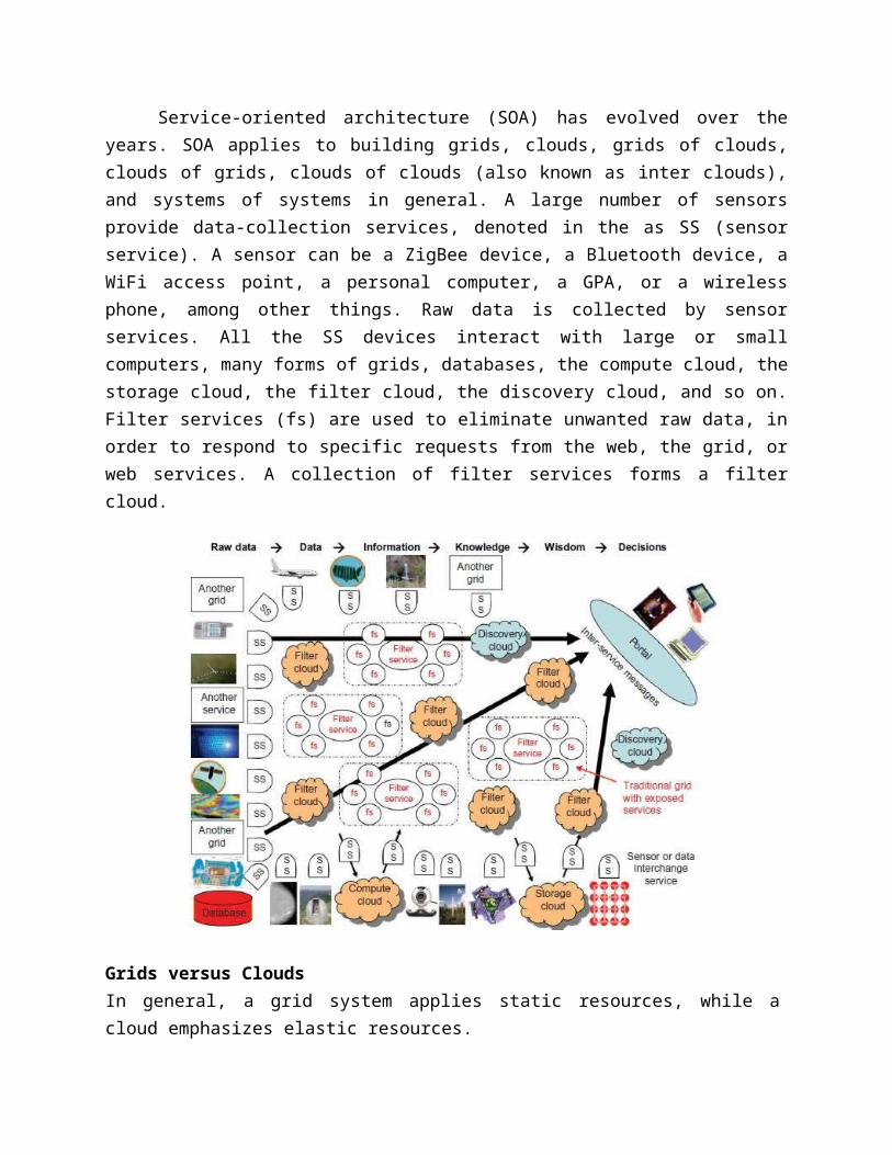
The Evolution of SOAService-oriented architecture (SOA) has evolved over the years. SOA applies to building
grids, clouds, grids of clouds, clouds of grids, clouds of clouds (also known as inter clouds), and systems of systems in general. A large number of sensors provide data-collection services, denoted in the as SS (sensor service). A sensor can be a ZigBee device, a Bluetooth device, a WiFi access point, a personal computer, a GPA, or a wireless phone, among other things. Raw data is collected by sensor services. All the SS devices interact with large or small computers, many forms of grids, databases, the compute cloud, the storage cloud, the filter cloud, the discovery cloud, and so on. Filter services (fs) are used to eliminate unwanted raw data, in order to respond to specific requests from the web, the grid, or web services. A collection of filter services forms a filter cloud.
Grids versus CloudsIn general, a grid system applies static resources, while a cloud emphasizes elastic resources.
One can build a grid out of multiple clouds. This type of grid can do a better job than a pure cloud, because it can explicitly support negotiated resource allocation.
Thus one may end up building with a system of systems: such as a cloud of clouds, a grid of clouds, or a cloud of grids, or inter-clouds as a basic SOA architecture.1.1.4.2 Trends toward Distributed Operating SystemsA distributed system inherently has multiple system images. Distributed OS that manages all resources coherently and efficiently. Such a system is most likely to be a closed system, and it will likely rely on message passing and RPCs for internode communications.
Distributed Operating SystemsTanenbaum identifies three approaches for distributing resource management functions in a distributed computer system.
1. The first approach is to build a network OS over a large number of heterogeneous OS platforms. Such an OS offers the lowest transparency to users, and is essentially a distributed file system, with independent computers relying on file sharing as a means of communication.
2. The second approach is to develop middleware to offer a limited degree of resource sharing, similar to the MOSIX/OS developed for clustered systems
3. The third approach is to develop a truly distributed OS to achieve higher use or system transparency.
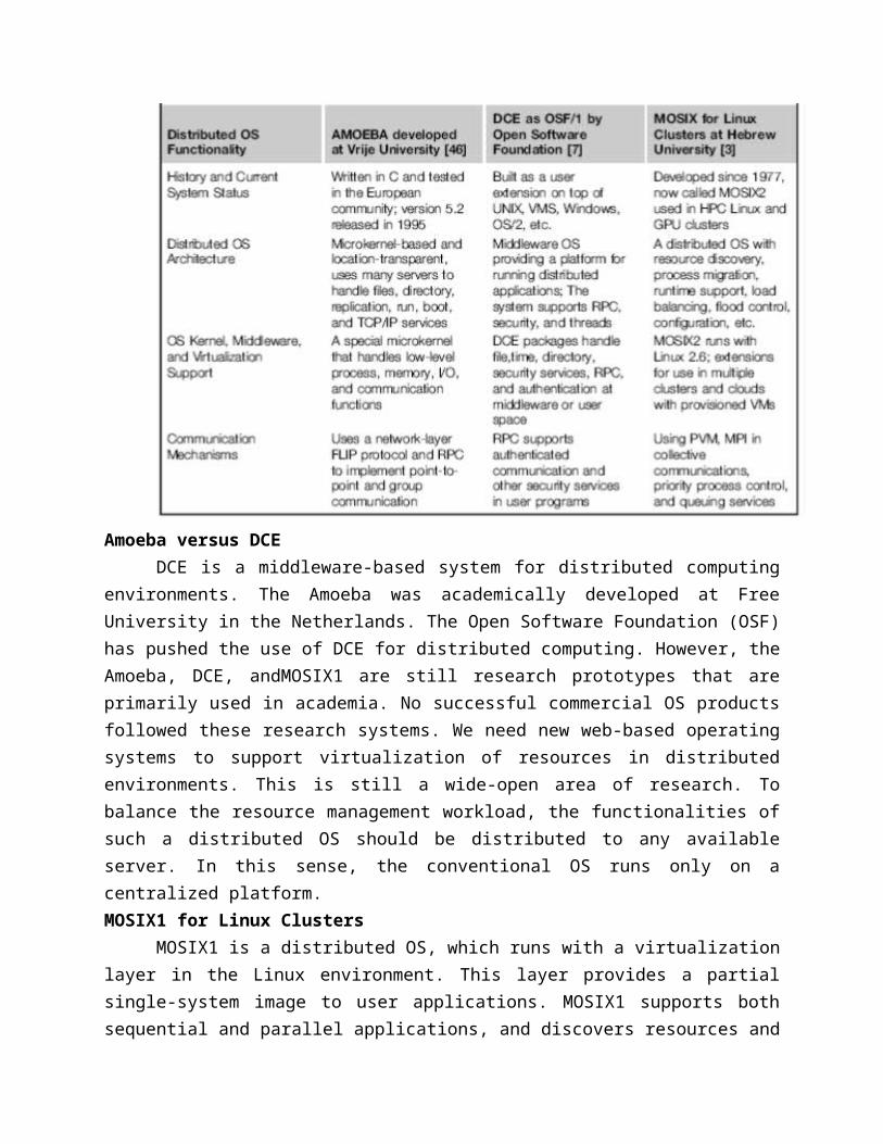
Table compares the functionalities of the three distributed operating systems.
Amoeba versus DCEDCE is a middleware-based system for distributed computing environments. The
Amoeba was academically developed at Free University in the Netherlands. The Open Software Foundation (OSF) has pushed the use of DCE for distributed computing. However, the Amoeba, DCE, andMOSIX1 are still research prototypes that are primarily used in academia. No successful commercial OS products followed these research systems. We need new web-based operating systems to support virtualization of resources in distributed environments. This is still a wide-open area of research. To balance the resource management workload, the functionalities of such a distributed OS should be distributed to any available server. In this sense, the conventional OS runs only on a centralized platform. MOSIX1 for Linux Clusters
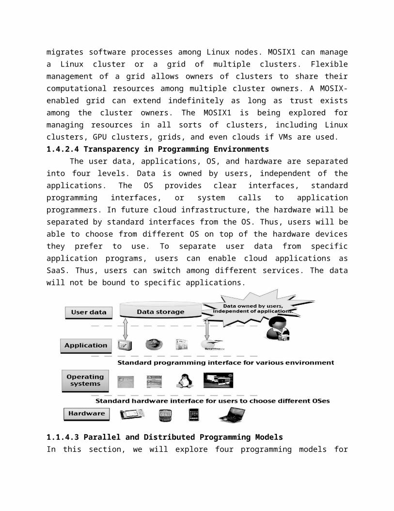
MOSIX1 is a distributed OS, which runs with a virtualization layer in the Linux environment. This layer provides a partial single-system image to user applications. MOSIX1 supports both sequential and parallel applications, and discovers resources and migrates software processes among Linux nodes. MOSIX1 can manage a Linux cluster or a grid of multiple clusters. Flexible management of a grid allows owners of clusters to share their computational resources among multiple cluster owners. A MOSIX-enabled grid can extend indefinitely as long as trust exists among the cluster owners. The MOSIX1 is being explored for managing resources in all sorts of clusters, including Linux clusters, GPU clusters, grids, and even clouds if VMs are used. 1.4.2.4 Transparency in Programming Environments The user data, applications, OS, and hardware are separated into four levels. Data is owned by users, independent of the applications. The OS provides clear interfaces, standard programming interfaces, or system calls to application programmers. In future cloud infrastructure, the hardware will be separated by standard interfaces from the OS. Thus, users will be able to choose from different OS on top of the hardware devices they prefer to use. To separate user data from specific application programs, users can enable cloud applications as SaaS. Thus, users can switch among different services. The data will not be bound to specific applications.
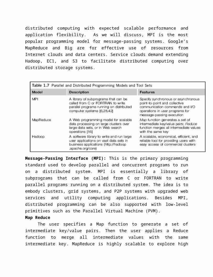
1.1.4.3 Parallel and Distributed Programming ModelsIn this section, we will explore four programming models for distributed computing with expected scalable performance and application flexibility. As we will discuss, MPI is the most popular programming model for message-passing systems. Google’s MapReduce and Big are for effective use of resources from Internet clouds and data centers. Service clouds demand extending Hadoop, EC1, and S3 to facilitate distributed computing over distributed storage systems.
Message-Passing Interface (MPI): This is the primary programming standard used to develop parallel and concurrent programs to run on a distributed system. MPI is essentially a library of subprograms that can be called from C or FORTRAN to write parallel programs running on a distributed system. The idea is to embody clusters, grid systems, and P2P systems with upgraded
web services and utility computing applications. Besides MPI, distributed programming can be also supported with low-level primitives such as the Parallel Virtual Machine (PVM). Map Reduce
The user specifies a Map function to generate a set of intermediate key/value pairs. Then the user applies a Reduce function to merge all intermediate values with the same intermediate key. MapReduce is highly scalable to explore high degrees of parallelism at different job levels. A typical MapReduce computation process can handle terabytes of data on tens of thousands or more client machines. Hundreds of MapReduce programs can be executed simultaneously; in fact, thousands of MapReduce jobs are executed on Google’s clusters every day.Hadoop Library
Hadoop offers a software platform that was originally developed by a Yahoo! group. The package enables users to write and run applications over vast amounts of distributed data. Users can easily scale Hadoop to store and process petabytes of data in the web space. Also, Hadoop is economical in that it comes with an open source version of MapReduce that minimizes overhead in task spawning and massive data communication. It is efficient, as it processes data with a high degree of parallelism across a large number of commodity nodes, and it is reliable in that it automatically keeps multiple data copies to facilitate redeployment of computing tasks upon unexpected system failures.Open Grid Services Architecture (OGSA)
The development of grid infrastructure is driven by large-scale distributed computing applications. These applications must count on a high degree of resource and data sharing. Genesis II is a realization of OGSA. Key features include a distributed execution environment, Public Key Infrastructure (PKI) services using a local certificate authority (CA), trust management, and security policies in grid computing.1.1.5 Performance, Security, and Energy Efficiency1.1.5.1 Performance Metrics and Scalability Analysis
Performance metrics are needed to measure various distributed systems.Performance Metrics
We discussed CPU speed in MIPS and network bandwidth in Mbps to estimate processor and network performance. In a distributed system, performance is attributed to a large number of factors. System throughput is often measured in MIPS, Tflops (tera floating-point operations per second), or TPS (transactions per second). Other measures include job response time and network latency. Other performance-related metrics include the QoS for Internet and web services; system availability and dependability; and security resilience for system defense against network attacks.Dimensions of ScalabilityThe following dimensions of scalability are characterized in parallel and distributed systems:Size scalability this refers to achieving higher performance or more functionality by increasing the machine size. The word “size” refers to adding processors, cache, and memory, storage, or I/O channels. The most obvious way to determine size scalability is to simply count the number of processors installed. Not all parallel computer or distributed architectures are equally size-
scalable. Software scalability this refers to upgrades in the OS or compilers, adding mathematical and engineering libraries, porting new application software, and installing more user-friendly programming environments. Some software upgrades may not work with large system configurations. Testing and fine-tuning of new software on larger systems is a nontrivial job.Application scalability this refers to matching problem size scalability with machine size scalability. Problem size affects the size of the data set or the workload increase. Instead of increasing machine size, users can enlarge the problem size to enhance system efficiency or cost-effectiveness.Technology scalability this refers to a system that can adapt to changes in building technologies, such as the component and networking technologies When scaling a system design with new technology one must consider three aspects: time, space, and heterogeneity.
(1) Time refers to generation scalability. When changing to new-generation processors, one must consider the impact to the motherboard, power supply, packaging and cooling, and so forth. Based on past experience, most systems upgrade their commodity processors every three to five years.
(2) Space is related to packaging and energy concerns. Technology scalability demands harmony and portability among suppliers.
(3) Heterogeneity refers to the use of hardware components or software packages from different vendors. Heterogeneity may limit the scalability.
Scalability versus OS Image Count: In Scalable performance implies that the system can achieve higher speed by adding more processors or servers, enlarging the physical node’s memory size, extending the disk capacity, or adding more I/O channels. The OS image is counted by the number of independent OS images observed in a cluster, grid, P2P network, or the cloud. SMP and NUMA are included in the comparison. An SMP (symmetric multiprocessor) server has a single system image, which could be a single node in a large cluster. By 2010 standards, the largest shared-memory SMP node was limited to a few hundred processors. The scalability of SMP systems is constrained primarily by packaging and the systems interconnect used.
NUMA (nonuniform memory access) machines are often made out of SMP nodes with distributed, shared memory. A NUMA machine can run with multiple operating systems, and can scale to a few thousand processors communicating with the MPI library. For example, a NUMA machine may have 2,048 processors running 32 SMP operating systems, resulting in 32 OS images in the 2,048-processor NUMA system. The cluster nodes can be either SMP servers or high-end machines that are loosely coupled together. Therefore, clusters have much higher scalability than NUMA machines.
The number of OS images in a cluster is based on the cluster nodes concurrently in use. The cloud could be a virtualized cluster. As of 2010, the largest cloud was able to scale up to a few thousand VMs. Therefore, the number of OS images in a large grid structure could be hundreds or thousands fewer than the total number of processors in the grid. A P2P network can
easily scale to millions of independent peer nodes, essentially desktop machines. P2P performanceAmdahl’s Law
Amdahl’s Law states that the speedup factor of using the n-processor system over the use of a single processor is expressed by:
Speedup = S = T/ [αT + (1 – α) T/n] = 1/ [α + (1 – α)/n]The maximum speed up of n is achieved only if the sequential bottleneck α is reduced to
zero or the code is fully parallelizable with α = 0. As the cluster becomes sufficiently large, that is, n →∞, S approaches 1/α, an upper bound on the speedup S. Surprisingly, this upper bound is independent of the cluster size n. The sequential bottleneck is the portion of the code that cannot be parallelized.Problem with Fixed Workload In Amdahl’s law, we have assumed the same amount of workload for both sequential and parallel execution of the program with a fixed problem size or data set. This was called fixed-workload speedup by Hwang and Xu . To execute a fixed workload on n processors, parallel processing may lead to a system efficiency defined as follows:
E = S/n = 1/[αn + 1 – α] Very often the system efficiency is rather low, especially when the cluster size is very large. To execute the aforementioned program on a cluster with n = 18 nodes, extremely low efficiency E = 1/[0.11 × 18 + 0.31] = 1.1% is observed. This is because only a few processors (say, 4) are kept busy, while the majority of the nodes are left idling.Gustafson’s Law
To achieve higher efficiency when using a large cluster, we must consider scaling the problem size to match the cluster capability. This leads to the following speedup law proposed by John Gustafson, referred as scaled-workload speedup. Let W be the workload in a given program. When using an n-processor system, the user scales the workload to: W′ = αW + (1 − α) nW.
Note that only the parallelizable portion of the workload is scaled n times in the second term. This scaled workload W′ is essentially the sequential execution time on a single processor. The parallel execution time of a scaled workload W′ on n processors is defined by a scaled-workload speedup as follows:
S′ = W′/W = [αW + (1 – α) nW]/W = α + (1 – α) nThis speedup is known as Gustafson’s law. By fixing the parallel execution time at level
W, the following efficiency expression is obtained: E′ = S′/n = α/n + (1 – α)
1.1.5.2 Fault Tolerance and System AvailabilityIn addition to performance, system availability and application flexibility are two other important design goals in a distributed computing system.System Availability
HA (high availability) is desired in all clusters, grids, P2P networks, and cloud systems. A system is highly available if it has a long mean time to failure (MTTF) and a short mean time
to repair (MTTR). System availability is formally defined as follows:System Availability = MTTF/(MTTF + MTTR)
1.1.5.3 Network Threats and Data IntegrityThis section introduces system vulnerability, network threats, defense countermeasures,
and copyright protection in distributed or cloud computing systems.Threats to Systems and Networks
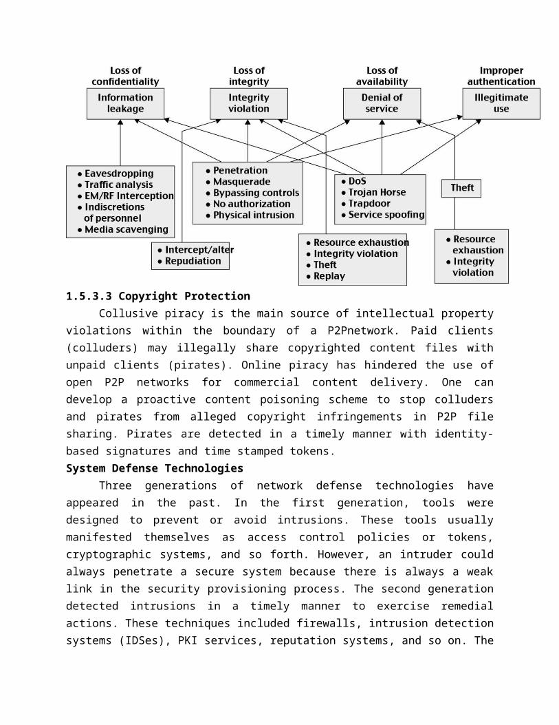
Network viruses have threatened many users in widespread attacks. These incidents have created a worm epidemic by pulling down many routers and servers, and are responsible for the loss of billions of dollars in business, government, and services. Figure summarizes various attack types and their potential damage to users. As the shows, information leaks lead to a loss of confidentiality. Loss of data integrity may be caused by user alteration, Trojan horses, and service spoofing attacks. A denial of service (DoS) results in a loss of system operation and Internet connections.
Lack of authentication or authorization leads to attackers’ illegitimate use of computing resources. Open resources such as data centers, P2P networks, and grid and cloud infrastructures could become the next targets. Users need to protect clusters, grids, clouds, and P2P systems. Otherwise; users should not use or trust them for outsourced work. Malicious intrusions to these systems may destroy valuable hosts, as well as network and storage resources. Internet anomalies found in routers, gateways, and distributed hosts may hinder the acceptance of these public-resource computing services.Security Responsibilities
Three security requirements are often considered: confidentiality, integrity, and availability for most Internet service providers and cloud users. In the order of SaaS, PaaS, and IaaS, the providers gradually release the responsibility of security control to the cloud users. In summary, the SaaS model relies on the cloud provider to perform all security functions. At the other extreme, the IaaS model wants the users to assume almost all security functions, but to leave availability in the hands of the providers. The PaaS model relies on the provider to maintain data integrity and availability, but burdens the user with confidentiality and privacy control.
1.5.3.3 Copyright ProtectionCollusive piracy is the main source of intellectual property violations within the boundary
of a P2Pnetwork. Paid clients (colluders) may illegally share copyrighted content files with unpaid clients (pirates). Online piracy has hindered the use of open P2P networks for commercial content delivery. One can develop a proactive content poisoning scheme to stop colluders and pirates from alleged copyright infringements in P2P file sharing. Pirates are detected in a timely manner with identity-based signatures and time stamped tokens. System Defense Technologies
Three generations of network defense technologies have appeared in the past. In the first generation, tools were designed to prevent or avoid intrusions. These tools usually manifested themselves as access control policies or tokens, cryptographic systems, and so forth. However, an intruder could always penetrate a secure system because there is always a weak link in the security provisioning process. The second generation detected intrusions in a timely manner to exercise remedial actions. These techniques included firewalls, intrusion detection systems (IDSes), PKI services, reputation systems, and so on. The third generation provides more intelligent responses to intrusions.Data Protection Infrastructure
Security infrastructure is required to safeguard web and cloud services. At the user level, one needs to perform trust negotiation and reputation aggregation over all users. At the application end, we need to establish security precautions in worm containment and intrusion detection against virus, worm, and distributed DoS (DDoS) attacks. 1.1.5.4 Energy Efficiency in Distributed ComputingEnergy Consumption of Unused Servers
To run a server farm (data center) a company has to spend a huge amount of money for hardware, software, operational support, and energy every year. Therefore, companies should
thoroughly identify whether their installed server farm (more specifically, the volume of provisioned resources) is at an appropriate level, particularly in terms of utilization. It was estimated in the past that, on average, one-sixth (15 percent) of the full-time servers in a company are left powered on without being actively used (i.e., they are idling) on a daily basis. This indicates that with 44 million servers in the world, around 4.7 million servers are not doing any useful work. Reducing Energy in Active Servers
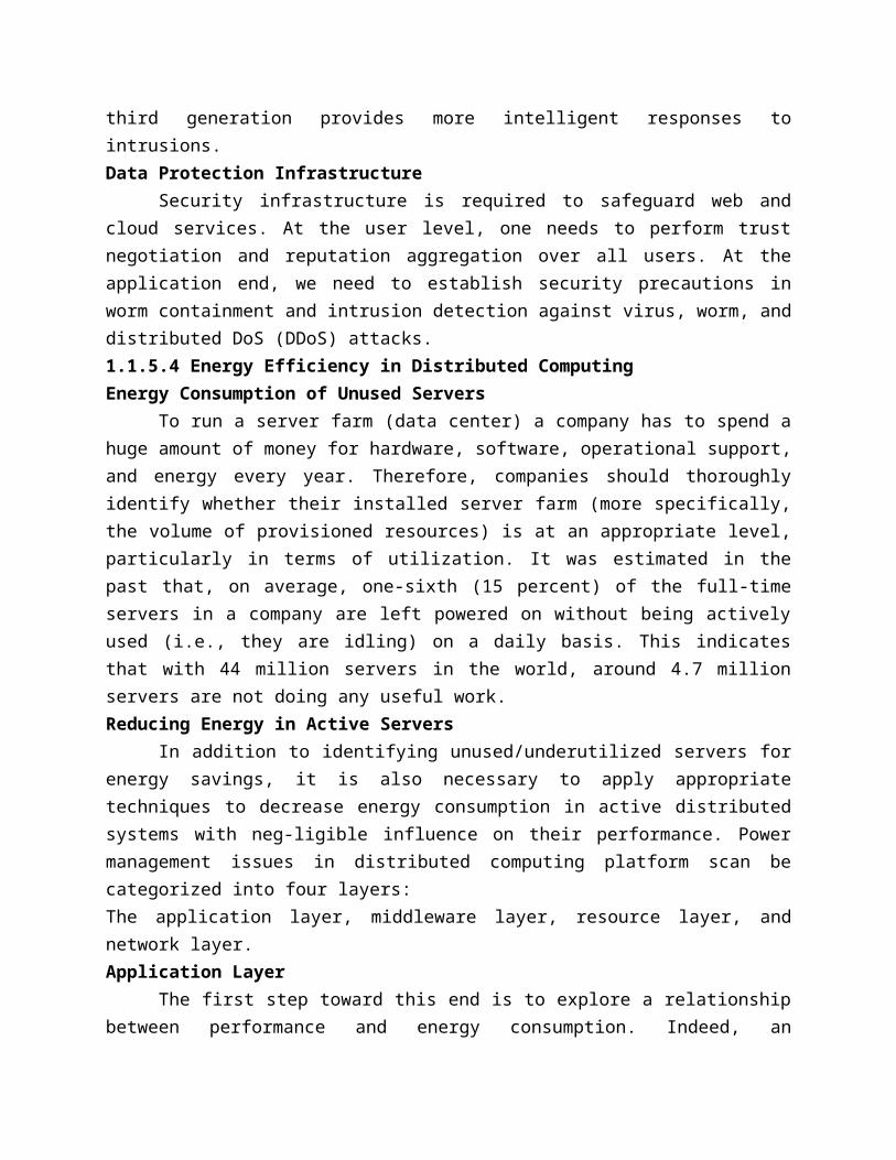
In addition to identifying unused/underutilized servers for energy savings, it is also necessary to apply appropriate techniques to decrease energy consumption in active distributed systems with neg-ligible influence on their performance. Power management issues in distributed computing platform scan be categorized into four layers:The application layer, middleware layer, resource layer, and network layer.Application Layer
The first step toward this end is to explore a relationship between performance and energy consumption. Indeed, an application’s energy consumption depends strongly on the number of instructions needed to execute the application and the number of transactions with the storage unit (or memory). These two factors (compute and storage) are correlated and they affect completion time.
Middleware LayerThe middleware layer acts as a bridge between the application layer and the resource
layer. This layer provides resource broker, communication service, task analyzer, task scheduler, security access, reliability control, and information service capabilities. It is also responsible for applying energy-efficient techniques, particularly in task scheduling. Resource Layer
The resource layer consists of a wide range of resources including computing nodes and storage units. This layer generally interacts with hardware devices and the operating system; therefore, it is responsible for controlling all distributed resources in distributed computing systems. Network Layer
Routing and transferring packets and enabling network services to the resource layer are the main responsibility of the network layer in distributed computing systems. The major challenge to build energy-efficient networks is, again, determining how to measure, predict, and create a balance between energy consumption and performance. Two major challenges to designing energy-efficient networks are:
The models should represent the networks comprehensively as they should give a full understanding of interactions among time, space, and energy.
New, energy-efficient routing algorithms need to be developed. New, energy-efficient protocols should be developed against network attacks.
1.2 Computer Clusters for Scalable Parallel Computing1.2.1 Clustering for Massive Parallelism
A computer cluster is a collection of interconnected stand-alone computers which can work together collectively and cooperatively as a single integrated computing resource pool. Clustering explores massive parallelism at the job level and achieves high availability (HA) through stand-alone operations. The benefits of computer clusters and massively parallel processors (MPPs) include scalable performance, HA, fault tolerance, modular growth, and use of commodity components. These features can sustain the generation changes experienced in hardware, software, and network components. 1.2.1.1 Cluster Development Trends
Support for clustering of computers has moved from interconnecting high-end mainframe computers to building clusters with massive numbers of x41 engines. Computer clustering started with the linking of large mainframe computers such as the IBM Sysplex and the SGI Origin 3000. Subsequently, the clustering trend moved toward the networking of many minicomputers, such as DEC’s VMS cluster, in which multiple VAXes were interconnected to share the same set of disk/tape controllers. Tandem’s Himalaya was designed as a business cluster for fault-tolerant online transaction processing (OLTP) applications.
Clustered products now appear as integrated systems, software tools, availability infrastructure, and operating system extensions. Milestone Cluster Systems
Clustering has been a hot research challenge in computer architecture. Fast communication, job scheduling, SSI, and HA are active areas in cluster research. Table lists some milestone cluster research projects and commercial cluster products.
The NOW project addresses a whole spectrum of cluster computing issues, including architecture, software support for web servers, single system image, I/O and file system, efficient communication, and enhanced availability. The Rice University TreadMarks is a good example of software-implemented shared-memory cluster of workstations. The memory sharing is implemented with a user-space runtime library. This was a research cluster built over Sun Solaris workstations. Some cluster OS functions were developed, but were never marketed successfully. 1.2.1.2 Design Objectives of Computer Clusters
Clusters have been classified in various ways in the literature. We classify clusters using six orthogonal attributes: scalability, packaging, control, homogeneity, programmability, and security.Scalability
Clustering of computers is based on the concept of modular growth. To scale a cluster from hundreds of uniprocessor nodes to a supercluster with 10,000 multicore nodes is a nontrivial task. The scalability could be limited by a number of factors, such as the multicore chip technology, cluster topology, packaging method, power consumption, and cooling scheme applied. The purpose is to achieve scalable performance constrained by the aforementioned factors. We have to also consider other limiting factors such as the memory wall, disk I/O bottlenecks, and latency tolerance, among others.PackagingCluster nodes can be packaged in a compact or a slack fashion.
In a compact cluster, the nodes are closely packaged in one or more racks sitting in a room, and the nodes are not attached to peripherals (monitors, keyboards, mice, etc.).
In a slack cluster, the nodes are attached to their usual peripherals (i.e., they are complete SMPs, workstations, and PCs), and they may be located in different rooms, different buildings,
or even remote regions. Packaging directly affects communication wire length, and thus the selection of interconnection technology used. While a compact cluster can utilize a high-bandwidth, low-latency communication network that is often proprietary, nodes of a slack cluster are normally connected through standard LANs or WANs.Control
A cluster can be either controlled or managed in a centralized or decentralized fashion. A compact cluster normally has centralized control, while a slack cluster can be controlled either way.
In a centralized cluster, all the nodes are owned, controlled, managed, and administered by a central opera-tor. In a decentralized cluster, the nodes have individual owners. Homogeneity
A homogeneous cluster uses nodes from the same platform, that is, the same processor architecture and the same operating system; often, the nodes are from the same vendors. A heterogeneous Cluster uses nodes of different platforms. Interoperability is an important issue in heterogeneous clusters. Security
Intra cluster communication can be either exposed or enclosed. In an exposed cluster, the communication paths among the nodes are exposed to the outside world. An outside machine can access the communication paths, and thus individual nodes, using standard protocols (e.g., TCP/IP). Such exposed clusters are easy to implement, but have several disadvantages:
Being exposed, intracluster communication is not secure, unless the communication subsystem performs additional work to ensure privacy and security.
Outside communications may disrupt intracluster communications in an unpredictable fashion. For instance, heavy BBS traffic may disrupt production jobs.
Standard communication protocols tend to have high overhead. Dedicated versus Enterprise Clusters
A dedicated cluster is typically installed in a deskside rack in a central computer room. It is homogeneously configured with the same type of computer nodes and managed by a single administrator group like a frontend host. Dedicated clusters are used as substitutes for traditional mainframes or supercomputers. A dedicated cluster is installed, used, and administered as a single machine. Many users can log in to the cluster to execute both interactive and batch jobs. The cluster offers much enhanced throughput, as well as reduced response time.
An enterprise cluster is mainly used to utilize idle resources in the nodes. Each node is usually a full-fledged SMP, workstation, or PC, with all the necessary peripherals attached. The nodes are typically geographically distributed, and are not necessarily in the same room or even in the same building. The nodes are individually owned by multiple owners. 1.2.1.3 Fundamental Cluster Design IssuesScalable Performance
This refers to the fact that scaling of resources (cluster nodes, memory capacity, I/O
bandwidth, etc.) leads to a proportional increase in performance. Of course, both scale-up and scale-down cap-abilities are needed, depending on application demand or cost-effectiveness considerations. Clustering is driven by scalability. One should not ignore this factor in all applications of cluster or MPP computing systems.Single-System Image (SSI)
A set of workstations connected by an Ethernet network is not necessarily a cluster. A cluster is a single system. Availability Support
Clusters can provide cost-effective HA capability with lots of redundancy in processors, memory, disks, I/O devices, networks, and operating system images. However, to realize this potential, avail-ability techniques are required. We will illustrate these techniques later in the book, when we dis-cuss how DEC clusters and the IBM SP1 attempt to achieve HA.Cluster Job Management
Clusters try to achieve high system utilization from traditional workstations or PC nodes that are normally not highly utilized. Job management software is required to provide batching, load balancing, parallel processing, and other functionality. We will study cluster job management systems Internode Communication
Because of their higher node complexity, cluster nodes cannot be packaged as compactly as MPP nodes. The internode physical wire lengths are longer in a cluster than in an MPP. This is true even for centralized clusters. A long wire implies greater interconnect network latency. But more importantly, longer wires have more problems in terms of reliability, clock skew, and cross talking. These problems call for reliable and secure communication protocols, which increase overhead. Clusters often use commodity networks (e.g., Ethernet) with standard protocols such as TCP/IP.Fault Tolerance and Recovery
Clusters of machines can be designed to eliminate all single points of failure. Through redundancy, a cluster can tolerate faulty conditions up to a certain extent. Heartbeat mechanisms can be installed to monitor the running condition of all nodes. In case of a node failure, critical jobs running on the failing nodes can be saved by failing over to the surviving node machines. Rollback recovery schemes restore the computing results through periodic checkpointing.Cluster Family ClassificationBased on application demand, computer clusters are divided into three classes:Compute clusters: These are clusters designed mainly for collective computation over a single large job. A good example is a cluster dedicated to numerical simulation of weather conditions. The compute clusters do not handle many I/O operations, such as database services. High-Availability clusters HA (high-availability) clusters are designed to be fault-tolerant and achieve HA of services. HA clusters operate with many redundant nodes to sustain faults or failures. The simplest HA cluster has only two nodes that can fail over to each other. Of course, high redundancy provides higher availability. HA clusters should be designed to avoid all single points of failure. Many commercial HA clusters are available for various operating systems.
Load-balancing clusters: These clusters shoot for higher resource utilization through load-balancing among all participating nodes in the cluster. All nodes share the workload or function as a single virtual machine (VM). Requests initiated from the user are distributed to all node computers to form a cluster. This results in a balanced workload among different machines, and thus higher resource utilization or higher performance. Middleware is needed to achieve dynamic load balancing by job or process migration among all the cluster nodes.1.2.1.4 Analysis of the Top 500 Supercomputers
Every six months, the world’s Top 500 supercomputers are evaluated by running the Linpack Benchmark program over very large data sets. The ranking varies from year to year, similar to a competitionArchitectural Evolution
It is interesting to observe the architectural evolution of the Top 500 supercomputers over the years. In 1993, 250 systems assumed the SMP architecture and these SMP systems all disappeared in June of 2002. Most SMPs are built with shared memory and shared I/O devices. There were 120 MPP systems built in 1993, MPPs reached the peak mof 350 systems in mod-200, and dropped to less than 100 systems in 2010. The single instruction, multiple data (SIMD) machines dis-appeared in 1997. The cluster architecture appeared in a few systems in 1999. The cluster systems are now populated in the Top-500 list with more than 400 systems as the dominating architecture class.
In 2010, the Top 500 architecture is dominated by clusters (420 systems) and MPPs (80 systems).The basic distinction between these two classes lies in the components they use to build the systems. Speed Improvement over Time Figure plots the measured performance of the Top 500 fastest computers from 1993 to 2010.The y-axis is scaled by the sustained speed performance in terms of Gflops, Tflops, and Pflops. The middle curve plots the performance of the fastest computers recorded over 17 years; the top curve plots the speed sum of all 500 computers over the same period. In 2010, the total speed sum of 43.3 Pflops was achieved by all 500 computers, collectively.
Operating System Trends in the Top 500The five most popular operating systems have more than a 10 percent share among the
Top 500 computers, According to the data, 410 supercomputers are using Linux with a total processor count exceeding 4.5 million. This constitutes 82 percent of the systems adopting Linux.
The IBM AIX/OS is in second place with 17 systems (a 3.4 percent share) and more than 94,288 processors.
Third place is represented by the combined use of the SLEs10 with the SGI ProPack, with 15 systems (3 percent) over 135,200 processors.
Fourth place goes to the CNK/SLES9 used by 14 systems (2.8 percent) over 1.13 million processors. The remaining 34 systems applied 13 other operating systems with a total share of only 6.8 percent. In conclusion, the LINUX OS dominates the systems in the Top 500 list. The Top Five Systems in 2010
Some of the top winners: namely the Tianhe-1A, Cray Jaguar, Nebulae, and IBM Roadrunner that were ranked among the top systems from 2008 to 2010. All the top five machines in have achieved a speed higher than 1 Pflops.
Among the top five systems, the two U.S.-built systems, the Jaguar and the Hopper, have the highest efficiency, more than 75 percent. The two systems built in China, the Tianhe-1A and the Nebulae, and Japan’s TSUBAME 2.0, are all low inefficiency. These top systems all emphasize massive parallelism using up to 250,000 processor cores per system.Country Share and Application Share
In the 2010 Top-500 list, there were 274 supercomputing systems installed in the US, 41 systems in China, and 103 systems in Japan, France, UK, and Germany. The remaining countries have 82 systems. This country share roughly reflects the countries’ economic growth over the years. Countries compete in the Top 500 race every six months. Major increases of supercomputer applications are in the areas of database, research, finance, and information services.1.2.2 Computer Clusters and MPP Architectures1.2.2.1 Cluster Organization and Resource Sharing
In this section, we will start by discussing basic, small-scale PC or server clusters. We will discuss how to construct large-scale clusters and MPPs in subsequent sections.A Basic Cluster Architecture
The shows a simple cluster of computers built with commodity components and fully supported with desired SSI features and HA capability. The processing nodes are commodity workstations, PCs, or servers. These commodity nodes are easy to replace or upgrade with new generations of hardware. The node operating systems should be designed for multiuser, multitasking, and multithreaded applications. The nodes are interconnected by one or more fast commodity networks. These networks use standard communication protocols and operate at a speed that should be two orders of magnitude faster than that of the current TCP/IP speed over Ethernet.
The network interface card is connected to the node’s standard I/O bus (e.g., PCI). When the processor or the operating system is changed, only the driver software needs to change. We
desire to have a platform-independent cluster operating system, sitting on top of the node platforms. But such a cluster OS is not commercially available. Instead, we can deploy some cluster middleware to glue together all node platforms at the user space. An availability middleware offers HA services. An SSI layer provides a single entry point, a single file hierarchy, a single point of control, and a single job management system. Single memory may be realized with the help of the compiler or a runtime library. A single process space is not necessarily supported.
In addition to running sequential user programs, the cluster supports parallel programming based on standard languages and communication libraries using PVM, MPI, or OpenMP. The programming environment also includes tools for debugging, profiling, monitoring, and so forth.
Resource Sharing in ClustersThe nodes of a cluster can be connected in one of three ways,
The shared-nothing architecture is used in most clusters, where the nodes are connected through the I/O bus. When one node fails, the other node takes over. The shared-nothing configuration simply connects two or more autonomous computers via a LAN such as Ethernet.
A shared-disk cluster. The shared disk can hold checkpoint files or critical system images to enhance cluster availability. Without shared disks, checkpointing, rollback recovery, failover, and failback are not possible in a cluster.
The shared-memory cluster is much more difficult to realize. The nodes could be connected by a scalable coherence interface (SCI) ring, which is connected to the memory bus of each node through an NIC module. In the other two architectures, the
interconnect is attached to the I/O bus. The memory bus operates at a higher frequency than the I/O bus.
1.2.2.2 Node Architectures and MPP PackagingIn building large-scale clusters or MPP systems, cluster nodes are classified into two
categories: compute nodes and service nodes. Compute nodes appear in larger quantities mainly used for large-scale searching or
parallel floating-point computations. Service nodes could be built with different processors mainly used to handle I/O, file
access, and system monitoring. 1.2.2.3 Cluster System InterconnectsHigh-Bandwidth Interconnects
The Myrinet and Quadrics perform in between. The MPI latency represents the state of the art in long-distance message passing. All four technologies can implement any network topology, including crossbar switches, fat trees, and torus networks. The InfiniBand is the most expensive choice with the fastest link speed. The Ethernet is still the most cost-effective choice. Share of System Interconnects over Time
Gigabit Ethernet is the most popular interconnect due to its low cost and market readiness. The InfiniBand network has been chosen in about 16 systems for its high-bandwidth performance. The Cray interconnect is designed for use in Cray systems only. 1.2.2.4 Hardware, Software, and Middleware Support
Realistically, SSI and HA features in a cluster are not obtained free of charge. They must be sup-ported by hardware, software, middleware, or OS extensions. Any change in hardware design and OS extensions must be done by the manufacturer. The hardware and OS support could be cost-prohibitive to ordinary users. However, programming level is a big burden to cluster users. There-fore, the middleware support at the application level costs the least to
implement. The middleware, OS extensions, and hardware support needed to achieve HA in a typical Linux cluster system. 1.2.3 Design Principles of Computer Clusters
Clusters should be designed for scalability and availability. In this section, we will cover the design principles of SSI, HA, fault tolerance, and rollback recovery in general-purpose computers and clusters of cooperative computers.1.2.3.1 Single-System Image FeaturesSSI does not mean a single copy of an operating system image residing in memory, as in an SMP or a workstation. Rather, it means the illusion of a single system, single control, symmetry, and transparency as characterized in the following list:Single system the entire cluster is viewed by users as one system that has multiple processors. The user could say, “Execute my application using five processors.” This is different from distributed system. Single control logically, an end user or system user utilizes services from one place with single interface. For instance, a user submits batch jobs to one set of queues; a system administrator cons all the hardware and software components of the cluster from one control point.Symmetry A user can use a cluster service from any node. In other words, all cluster services and functionalities are symmetric to all nodes and all users, except those protected by access rights.Location-transparent The user is not aware of the where abouts of the physical device that eventually provides a service. For instance, the user can use a tape drive attached to any cluster node as though it were physically attached to the local node.
The main motivation to have SSI is that it allows a cluster to be used, controlled, and maintained as a familiar workstation is. The word “single” in “single-system image” is sometimes synonymous with “global” or “central.”
A main requirement (and advantage) of SSI techniques is that they provide both the performance benefits of distributed implementation and the usability benefits of a single image. From the viewpoint of a process P, cluster nodes can be classified into three types. The home node of a process P is the node where P resided when it was created. The local node of a process P is the node where P currently resides. All other nodes are remote nodes to P. The illusion of an SSI can be obtained at several layers, three of which are discussed in the following list. Note that these layers may overlap with one another.Application software layer Two examples are parallel web servers and various parallel databases. The user sees an SSI through the application and is not even aware that he is using a cluster. This approach demands the modification of workstation or SMP applications for clusters. Hardware or kernel layer Ideally, SSI should be provided by the operating system or by the hardware. Unfortunately, this is not a reality yet. Furthermore, it is extremely difficult to provide an SSI over heterogeneous clusters. With most hardware architectures and operating systems being proprietary, only the manufacturer can use this approach.Middleware layer The most viable approach is to construct an SSI layer just above the OS
kernel. This approach is promising because it is platform-independent and does not require application modification. Many cluster job management systems have already adopted this approach.Single Entry Point
Single-system image (SSI) is a very rich concept, consisting of single entry point, single file hierarchy, single I/O space, single networking scheme, single control point, single job management system, single memory space, and single process space. The single entry point enables users to log in (e.g., through Telnet, rlogin, or HTTP) to a cluster as one virtual host, although the cluster may have multiple physical host nodes to serve the login sessions. The system transparently distributes the user’s login and connection requests to different physical hosts to balance the load. Single File Hierarchy
We use the term “single file hierarchy” in this book to mean the illusion of a single, huge file sys-tem image that transparently integrates local and global disks and other file devices (e.g., tapes). In other words, all files a user needs are stored in some subdirectories of the root directory /, and they can be accessed through ordinary UNIX calls such as open, read, and so on. The functionalities of a single file hierarchy have already been partially provided by existing distributed file systems such as Network File System (NFS) and Andrew File System (AFS). From the view-point of any process, files can reside on three types of locations in a cluster, Visibility of Files
The term “visibility” here means a process can use traditional UNIX system or library calls such asfopen, fread, and fwrite to access files. Support of Single-File Hierarchy
It is desired that a single file hierarchy have the SSI properties discussed, which are reiterated for file systems as follows:Single system There is just one file hierarchy from the user’s viewpoint.Symmetry A user can access the global storage (e.g., /scratch) using a cluster service from any node. In other words, all file services and functionalities are symmetric to all nodes and all users, except those protected by access rights.Location-transparent The user is not aware of the whereabouts of the physical device that eventually provides a serviceSingle I/O, Networking, and Memory Space
To achieve SSI, we desire a single control point, a single address space, a single job management system, a single user interface, and a single process control.Single Networking: A properly designed cluster should behave as one system (the shaded area).In other words, it is like a big workstation with four network connections and four I/O devices attached. Any process on any node can use any network and I/O device as though it were attached to the local node. Single networking means any node can access any network connection.Single Point of Control: The system administrator should be able to con, monitor, test, and control the entire cluster and each individual node from a single point.
Note that single point of control does not mean all system administration work should be carried out solely by the system console. In reality, many administrative functions are distributed across the cluster. It means that controlling a cluster should be no more difficult than administering an SMP or a mainframe. It implies that administration-related system information (such as various configuration files) should be kept in one logical place. Single Memory Space: Single memory space gives users the illusion of a big, centralized main memory, which in reality may be a set of distributed local memory spaces. A good way to test if a cluster has a single memory space is to run a sequential program that needs a memory space larger than any single node can provide. Other Desired SSI Features
The ultimate goal of SSI is for a cluster to be as easy to use as a desktop computer. Here are additional types of SSI, which are present in SMP servers:Single job management system All cluster jobs can be submitted from any node to a single job management system.Single user interface The users use the cluster through a single graphical interface. Such an interface is available for workstations and PCs. A good direction to take in developing a cluster GUI is to utilize web technology.Single process space All user processes created on various nodes form a single process spaceand share a uniform process identification scheme. A process on any node can create (e.g., through a UNIX fork) or communicate with (e.g., through signals, pipes, etc.) processes on remote nodes.Middleware support for SSI clustering, various SSI features are supported by middleware developed at three cluster application levels:Management level This level handles user applications and provides a job management system such as GLUnix, MOSIX, Load Sharing Facility (LSF), or Codine.Programming level This level provides single file hierarchy (NFS, xFS, AFS, Proxy) and distributed shared memory (TreadMark, Wind Tunnel).Implementation level This level supports a single process space, checkpointing, process migration, and a single I/O space. These features must interface with the cluster hardware and OS platform
1.2.3.2 High Availability through RedundancyWhen designing robust, highly available systems three terms are often used together:
reliability, availability, and serviceability (RAS). Availability is the most interesting measure since it combines the concepts of reliability and serviceability as defined here:
• Reliability measures how long a system can operate without a breakdown.• Availability indicates the percentage of time that a system is available to the user, that is,
the percentage of system uptime.• Serviceability refers to how easy it is to service the system, including hardware and
software maintenance, repair, upgrades, and so on. Availability and Failure Rate
A computer system operates normally for a period of time before it fails. The failed system is then repaired, and the system returns to normal operation. This operate-repair cycle then repeats. A system’s reliability is measured by the mean time to failure (MTTF), which is the average time of normal operation before the system (or a component of the system) fails. The metric for serviceability is the mean time to repair (MTTR), which is the average time it takes to repair the system and restore it to working condition after it fails. The availability of a system is defined by:
Availability = MTTF/(MTTF + MTTR)Planned versus Unplanned Failure
When studying RAS, we call any event that prevents the system from normal operation a failure. This includes:Unplanned failures The system breaks, due to an operating system crash, a hardware failure, network disconnection, human operation errors, a power outage, and so on. All these are simply called failures. The system must be repaired to correct the failure. Planned shutdowns The system is not broken, but is periodically taken off normal operation for upgrades, reconfiguration, and maintenance. A system may also be shut down for weekends or holidays. The MTTR for this type of failure is the planned downtime.
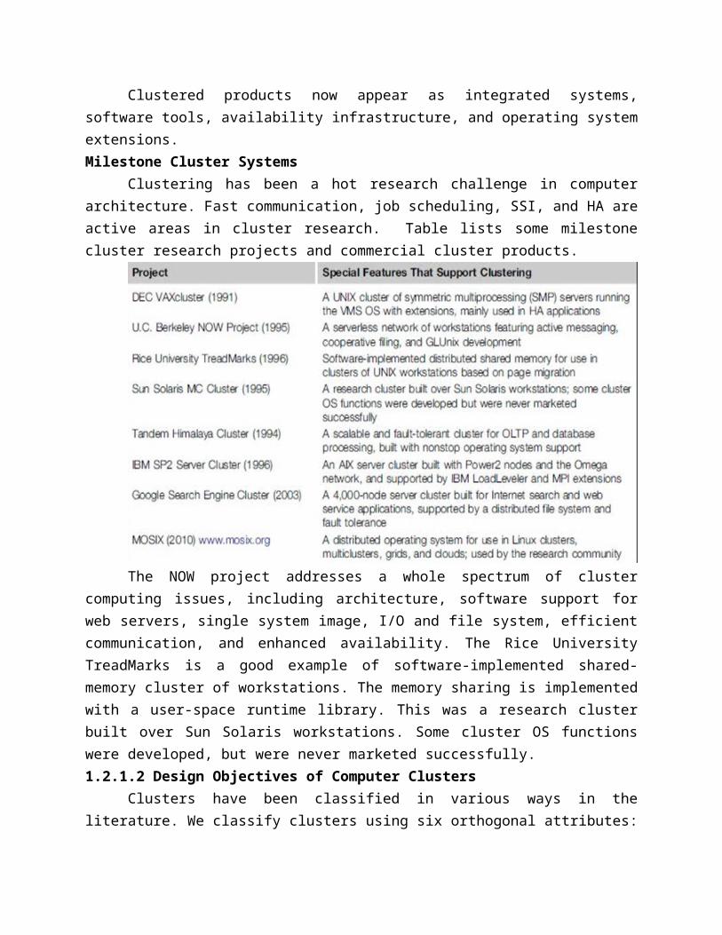
Transient versus Permanent FailuresA lot of failures are transient in that they occur temporarily and then disappear. They can
be dealt with without replacing any components. A standard approach is to roll back the system to a known state and start over. For instance, we all have rebooted our PC to take care of transient failures such as a frozen keyboard or window. Permanent failures cannot be corrected by rebooting. Some hard-ware or software component must be repaired or replaced. For instance, rebooting will not work if the system hard disk is broken.Partial versus Total Failures
A failure that renders the entire system unusable is called a total failure. A failure that only affects part of the system is called a partial failure if the system is still usable, even at a reduced capacity. Redundancy Techniques
Assume only the nodes can fail. The rest of the system (e.g. Interconnect and the shared RAID disk) is 100 percent available. Also assume that when a node fails, its workload is switched over to the other node in zero time. We ask, what is the availability of the cluster if planned downtime is ignored? What is the availability if the cluster needs one hour/week for maintenance? What is the availability if it is shut down one hour/week, one node at a time? If a workstation is available 55 percent of the time. The time both nodes are down is only 0.01 percent. Thus, the availability is 55.55 percent. It is now a fault-resilient sys-tem, with only one hour of downtime per year. The planned downtime is 8 hours per year, that is, 8 / (311 × 14) = 0.0015. The total downtime is now 0.15 percent + 0.01 percent = 0.1 percent. The availability of the cluster becomes 55.4 percent. Suppose we ignore the unlikely situation in which the other node fails while one node is maintained.
Then the availability is 55.55 percent. There are basically two ways to increase the availability of a system: increasing MTTF or reducing MTTR. Increasing MTTF amounts to increasing the reliability of the system. Isolated Redundancy
Furthermore, the primary and the backup components should be isolated from each other, meaning they should not be subject to the same cause of failure. Clusters provide HA with redundancy in power supplies, fans, processors, memories, disks, I/O devices, net-works, operating system images, and so on. In a carefully designed cluster, redundancy is also isolated. Isolated redundancy provides several benefits:
First, a component designed with isolated redundancy is not a single point of failure, and the failure of that component will not cause a total system failure.
Second, the failed component can be repaired while the rest of the system is still working.
Third, the primary and the backup components can mutually test and debug each other. The IBM SP1 communication subsystem is a good example of isolated-redundancy designN-Version Programming to Enhance Software Reliability
A common isolated-redundancy approach to constructing a mission-critical software system is called N-version programming. The software is implemented by N isolated teams who
may not even know the others exist. In a fault-tolerant system, the N versions all run simultaneously and their results are constantly compared. If the results differ, the system is notified that a fault has occurred. But because of isolated redundancy, it is extremely unlikely that the fault will cause a majority of the N versions to fail at the same time. So the system continues working, with the correct result generated by majority voting. In a highly available but less mission-critical system, only one version needs to run at a time. Each version has a built-itself-test capability. When one version fails, another version can take over.1.2.3.3 Fault-Tolerant Cluster Configurations
The cluster solution was targeted to provide availability support for two server nodes with three ascending levels of availability: hot standby, active takeover, and fault-tolerant. In this section, we will consider the recovery time, failback feature, and node activeness. The level of availability increases from standby to active and fault-tolerant cluster configurations. The shorter is the recovery time, the higher is the cluster availability. Failback refers to the ability of a recovered node returning to normal operation after repair or maintenance. Activeness refers to whether the node is used inactive work during normal operation.
Hot standby server clusters In a hot standby cluster, only the primary node is actively doing all the useful work normally. The standby node is powered on (hot) and running some monitoring programs to communicate heartbeat signals to check the status of the primary node, but is not actively running other useful workloads. The primary node must mirror any data to shared disk storage, which is accessible by the standby node. The standby node requires second copy of data. Active-takeover clusters In this case, the architecture is symmetric among multiple server nodes. Both servers are primary, doing useful work normally. Both failover and failback are often supported on both server nodes. When a node fails, the user applications fail over to the available node in the cluster. Depending on the time required to implement the failover, users may experience some delays or may lose some data that was not saved in the last checkpoint. Failover cluster This is probably the most important feature demanded in current clusters for commercial applications. When a component fails, this technique allows the remaining system to take over the services originally provided by the failed component. A failover mechanism must provide several functions, such as failure diagnosis, failure notification, and failure recovery. Failure diagnosis refers to the detection of a failure and the location of the failed component that caused the failure. A commonly used technique is heartbeat, whereby the cluster nodes send out a stream of heartbeat messages to one another. If the system does not receive the stream of heartbeat messages from a node, it can conclude that either the node or the network connection has failed.Recovery Schemes
Failure recovery refers to the actions needed to take over the workload of a failed component. There are two types of recovery techniques. In backward recovery, the processes running on a cluster periodically save a consistent state (called a checkpoint) to a stable storage. After a failure, the system is reconfigured to isolate the failed component, restores the previous checkpoint, and resumes nor-mal operation. This is called rollback
Checkpointing and Recovery TechniquesCheckpointing and recovery are two techniques that must be developed hand in hand to
enhance the availability of a cluster system. We will start with the basic concept of checkpointing. This is the process of periodically saving the state of an executing program to s storage, from which the system can recover after a failure. Each program state saved is called a checkpoint. The disk file that contains the saved state is called the checkpoint file. Although all current checkpointing soft-ware saves program states in a disk, research is underway to use node memories in place of stable storage in order to improve performance.
Checkpointing techniques are useful not only for availability, but also for program debugging, process migration, and load balancing. Many job management systems and some operating systems support checkpointing to a certain degreeKernel, Library, and Application Levels
Checkpointing can be realized by the operating system at the kernel level, where the OS transparently checkpoints and restarts processes. This is ideal for users. However, checkpointing is not supported in most operating systems, especially for parallel programs. A less transparent approach links the user code with a checkpointing library in the user space. Checkpointing and restarting are handled by this runtime support. This approach is used widely because it has the advantage that user applications do not have to be modified. A main problem is that most current checkpointing libraries are static, meaning the application source code (or at least the object code) must be available. It does not work if the application is in the form of execution code. A third approach requires the user (or the compiler) to insert check-pointing functions in the application; thus, the application has to be modified, and the transparency is lost. However, it has the advantage that the user can specify where to checkpoint. This is helpful to reduce checkpointing overhead. Checkpointing incurs both time and storage overheads.Checkpoint Overheads
During a program’s execution, its states may be saved many times. This is denoted by the time consumed to save one checkpoint. The storage overhead is the extra memory and disk space required for checkpointing. Both time and storage overheads depend on the size of the checkpoint file. The overheads can be substantial, especially for applications that require a large memory space. A number of techniques have been suggested to reduce these overheads.Choosing an Optimal Checkpoint IntervalThe time period between two checkpoints is called the checkpoint interval. Making the interval larger can reduce checkpoint time overhead. However, this implies a longer computation time after failure.
Optimal checkpoint interval = Square root (MTTF x tc )/h Here, MTTF is the system’s mean time to failure. This MTTF accounts the time consumed to save one checkpoint, and h is the average percentage of normal computation performed in a check-point interval before the system fails. Incremental Checkpoint
Instead of saving the full state at each checkpoint, an incremental checkpoint scheme saves only the portion of the state that is changed from the previous checkpoint. However, care
must be taken regarding old checkpoint files. In full-state checkpointing, only one checkpoint file needs to be kept on disk. Subsequent checkpoints simply overwrite this file. With incremental checkpointing, old files needed to be kept, because a state may span many files. Thus, the total storage requirement is larger.Forked Checkpointing
The forked child process duplicates the parent process’s address space and checkpoints it. Meanwhile, the parent process continues execution. Overlapping is achieved since checkpointing is disk-I/O intensive. A further optimization is to use the copy-on-write mechanism.User-Directed Checkpointing
The checkpoint overheads can sometimes be substantially reduced if the user inserts code (e.g. Library or system calls) to tell the system when to save, what to save, and what not to save. What should be the exact contents of a checkpoint? It should contain just enough information to allow a system to recover. The state of a process includes its data state and control state. For a UNIX process, these states are stored in its address space, including the text (code), the data, the stack segments, and the process descriptor. Saving and restoring the full state is expensive and sometimes impossible.
For instance, the process ID and the parent process ID are not restorable, nor do they need to be saved in many applications. Most checkpointing systems save a partial state. For instance, the code segment is usually not saved, as it does not change in most applications. What kinds of applications can be checkpointed? Current checkpoint schemes require programs to be well behaved, the exact meaning of which differs in different schemes. At a minimum, a well-behaved program should not need the exact contents of state information that is not restorable, such as the numeric value of a process ID.Checkpointing Parallel Programs
We now turn to checkpointing parallel programs. The state of a parallel program is usually much larger than that of a sequential program, as it consists of the set of the states of individual processes, plus the state of the communication network. Parallelism also introduces various timing and consistency problems. (Represented by dots), one from every process. In addition, some communication states may need to be saved. The intersection of a snapshot line with a process’s time line indicates where the process should take a (local) checkpoint. Thus, the program’s snapshot c consists of three local checkpoints: s, t, u for processes P, Q, and R, respectively, plus saving the communication y.Consistent Snapshot
A global snapshot is called consistent if there is no message that is received by the checkpoint of one process, but not yet sent by another process. Graphically, this corresponds to the case that no narrow crosses a snapshot line from right to left. Thus, snapshot a is consistent, because arrow x is from left to right. But snapshot c is inconsistent, as y goes from right to left. To be consistent, there should not be any zigzag path between two checkpoints. For instance, checkpoints u and s can-not belong to a consistent global snapshot. A stronger consistency requires that no arrows cross the snapshot. Coordinated versus Independent Checkpointing
Checkpointing schemes for parallel programs can be classified into two types. In coordinated check-pointing (also called consistent checkpointing), the parallel program is frozen, and all processes are checkpointed at the same time. In independent checkpointing, the processes are checkpointed independent of one another. These two types can be combined in various ways. Coordinated check-pointing is difficult to implement and tends to incur a large overhead. Independent checkpointing has a small overhead and can utilize existing checkpointing schemes for sequential programs.1.2.4 Cluster Job and Resource Management
This section covers various scheduling methods for executing multiple jobs on a clustered system. 1.2.4.1 Cluster Job Scheduling MethodsCluster jobs may be scheduled to run at a specific time (calendar scheduling) or when a particular event happens (event scheduling).
• Jobs are scheduled according to priorities based on submission time, resource nodes, execution time, memory, disk, job type, and user identity. With static priority, jobs are assigned priorities according to a predetermined, fixed scheme. A simple scheme is to schedule jobs in a first-come, first-serve fashion. Another scheme is to assign different priorities to users. With dynamic priority, the priority of a job may change over time.
• Three schemes are used to share cluster nodes. In the dedicated mode, only one job runs in the cluster at a time, and at most, one process of the job is assigned to a node at a time. The single job runs until completion before it releases the cluster to run other jobs. Note that even in the dedicated mode, some nodes may be reserved for system use and not be open to the user job. Other than that, all cluster resources are devoted to run a single job. This may lead to poor system utilization.
• The job resource requirement can be static or dynamic. Static scheme fixes the number of nodes for a single job for its entire period. Static scheme may underutilize the cluster resource. It cannot handle the situation when the needed nodes become unavailable, such as when the workstation owner shuts down the machine.
• Dynamic resource allows a job to acquire or release nodes during execution. However, it is much more difficult to implement, requiring cooperation between a running job and the Java Message Service (JMS). The jobs make asynchronous requests to the JMS to add/delete resources. The JMS needs to notify the job when resources become available.
• The synchrony means that a job should not be delayed (blocked) by the request/notification. Cooperation between jobs and the JMS requires modification of the programming languages/libraries.
• A primitive mechanism for such cooperation exists in PVM and MPI.Space Sharing
A common scheme is to assign higher priorities to short, interactive jobs in daytime and during evening hours using tiling. In this space-sharing mode, multiple jobs can run on disjointed partitions (groups) of nodes simultaneously. At most, one process is assigned to a node at a time.
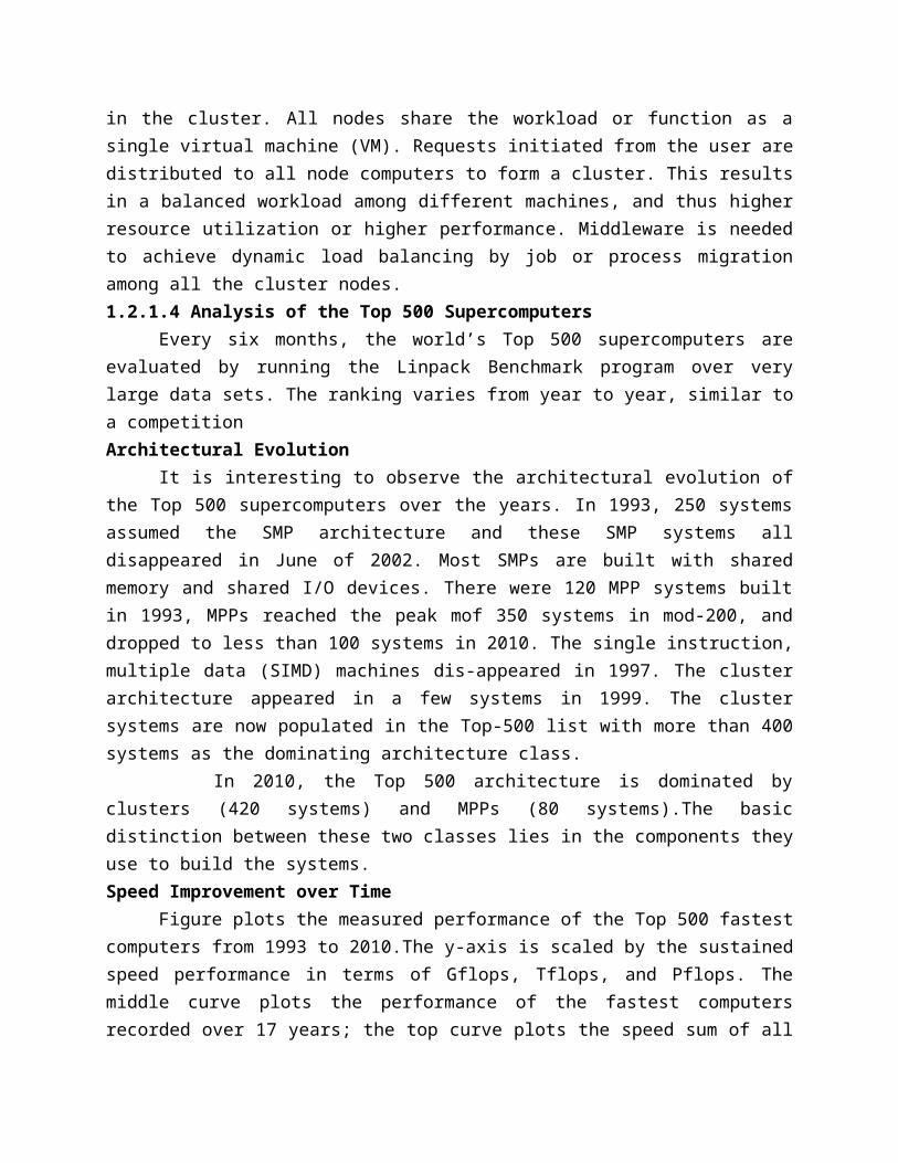
Although a partition of nodes is dedicated to a job, the interconnect and the I/O subsystem may be shared by all jobs. Space sharing must solve the tiling problem and the large-job problem.
Time SharingIn the time-sharing mode, multiple user processes are assigned to the same node. Time
sharing introduces the following parallel scheduling policies:1. Independent scheduling The most straightforward implementation of time sharing is to use the operating system of each cluster node to schedule different processes as in a traditional workstation. This is called local scheduling or independent scheduling. For instance, when one process wants to barrier-synchronize with another, the latter may be scheduled out. So the first process has to wait. As the second process is rescheduled, the first process may be swapped out.2. Gang scheduling The gang scheduling scheme schedules all processes of a parallel job together. When one process is active, all processes are active. The cluster nodes are not perfectly clock-synchronized. In fact, most clusters are asynchronous systems, and are not driven by the same clock. Although we say, “All processes are scheduled to run at the same time,” they do not start exactly at the same time. Gang-scheduling skew is the maximum difference between the time the first process starts and the time the last process starts. The execution time of a parallel job increases as the gang-scheduling skew becomes larger, leading to longer execution time. We should use a homogeneous cluster, where gang scheduling is more effective. However, gang scheduling is not yet realized in most clusters, because of implementation difficulties.3. Competition with foreign (local) jobs Scheduling becomes more complicated when both cluster jobs and local jobs are running. Local jobs should have priority over cluster jobs. With one keystroke, the owner wants command of all workstation resources. There are basically two ways to deal with this situation: The cluster job can either stay in the workstation node or migrate to another idle node. A stay scheme has the advantage of avoiding migration cost. The cluster process can be run at the lowest priority. The workstation’s cycles can be divided into three portions, for kernel processes, local processes, and cluster processes. However, to stay slows down both the local and the cluster jobs, especially when the cluster job is a load- balanced parallel job that needs frequent synchronization and communication. This leads to the migration approach to flow the jobs around available nodes, mainly for balancing the workload.1.2.4.2 Cluster Job Management Systems
Job management is also known as workload management, load sharing, or load management. We will first discuss the basic issues facing a job management system and summarize the available soft-ware packages. A Job Management System (JMS) should have three parts:
A user server lets the user submit jobs to one or more queues, specify resource requirements for each job, delete a job from a queue, and inquire about the status of a job or a queue.A job scheduler performs job scheduling and queuing according to job types, resource requirements, resource availability, and scheduling policies.A resource manager allocates and monitors resources, enforces scheduling policies, and collects accounting information.JMS Administration
The functionality of a JMS is often distributed. For instance, a user server may reside in each host node, and the resource manager may span all cluster nodes. However, the administration of a JMS should be centralized. All configuration and log files should be maintained in one location. There should be a single user interface to use the JMS. The administrator or the JMS should be able to cleanly suspend or kill any job. Clean means that when a job is suspended or killed, all its processes must be included. Otherwise, some “orphan” processes are left in the system, which wastes cluster resources and may eventually render the system unusable.Cluster Job TypesSeveral types of jobs execute on a cluster. Serial jobs run on a single node. Parallel jobs use multiple nodes. Interactive jobs are those that require fast turnaround time, and their input/output is directed to a terminal. These jobs do not need large resources, and users expect them to execute immediately, not to wait in a queue. Batch jobs normally need more resources, such as large memory space and long CPU time. But they do not need immediate responses. They are submitted to a job queue to be scheduled to run when the resource becomes available (e.g., during off hours).
While both interactive and batch jobs are managed by the JMS, foreign jobs are created outside the JMS. For instance, when a network of workstations is used as a cluster, users can submit inter-active or batch jobs to the JMS. Meanwhile, the owner of a workstation can start a foreign job at any time, which is not submitted through the JMS. Such a job is also called a local job, as opposed to cluster jobs (interactive or batch, parallel or serial) that are submitted through the JMS of the cluster. The characteristic of a local job is fast response time. The owner wants all resources to exe-cute his job, as though the cluster jobs did not exist.Characteristics of a Cluster Workload
To realistically address job management issues, we must understand the workload behavior of clusters. It may seem ideal to characterize workload based on long-time operation data on real clusters. The parallel workload traces include both development and production jobs. These traces are then fed to a simulator to generate various statistical and performance results, based on different sequential and parallel workload combinations, resource allocations, and scheduling policies. Migration SchemesA migration scheme must consider the following three issues:Node availability This refers to node availability for job migration. The Berkeley NOW project has reported such opportunity does exist in university campus environment. Even during peak
hours, 10 percent of workstations in a cluster are available at Berkeley campus.Migration overhead What is the effect of the migration overhead? The migration time can significantly slow down a parallel job. It is important to reduce the migration overhead (e.g., by improving the communication subsystem) or to migrate only rarely. The slowdown is significantly reduced if a parallel job is run on a cluster of twice the size. For instance, for a31-node parallel job run on a 10-node cluster, the slowdown caused by migration is no more than 10 percent, even when the migration time is as long as three minutes. This is because more nodes are available, and thus the migration demand is less frequent.Recruitment threshold What should be the recruitment threshold? In the worst scenario, right after a process migrates to a node, the node is immediately claimed by its owner. Thus, the process has to migrate again, and the cycle continues. The recruitment threshold is the amount of time a workstation stays unused before the cluster considers it an idle node.Desired Features in A JMS
Here are some features that have been built in some commercial JMSes in cluster computing applications:
Most support heterogeneous Linux clusters. All support parallel and batch jobs. However, Connect: Queue does not support interactive jobs.
Enterprise cluster jobs are managed by the JMS. They will impact the owner of a workstation in running local jobs. However, NQE and PBS allow the impact to be adjusted. In DQS, the impact can be configured to be minimal.
All packages offer some kind of load-balancing mechanism to efficiently utilize cluster resources. Some packages support checkpointing.
Most packages cannot support dynamic process migration. They support static migration: A process can be dispatched to execute on a remote node when the process is first created.
However, once it starts execution, it stays in that node. A package that does support dynamic process migration is Condor.
All packages allow dynamic suspension and resumption of a user job by the user or by the administrator. All packages allow resources (e.g., nodes) to be dynamically added to or deleted.
Most packages provide both a command-line interface and a graphical user interface. Besides UNIX security mechanisms, most packages use the Kerberos authentication system.
1.2.4.3 Load Sharing Facility (LSF) for Cluster ComputingLSF is a commercial workload management system from Platform Computing. LSF
emphasizes job management and load sharing on both parallel and sequential jobs. In addition, it supports checkpointing, availability, load migration, and SSI. LSF is highly scalable and can support a cluster of thousands of nodes. LSF has been implemented for various UNIX and Windows/NT plat-forms. Currently, LSF is being used not only in clusters but also in grids and clouds.LSF Architecture
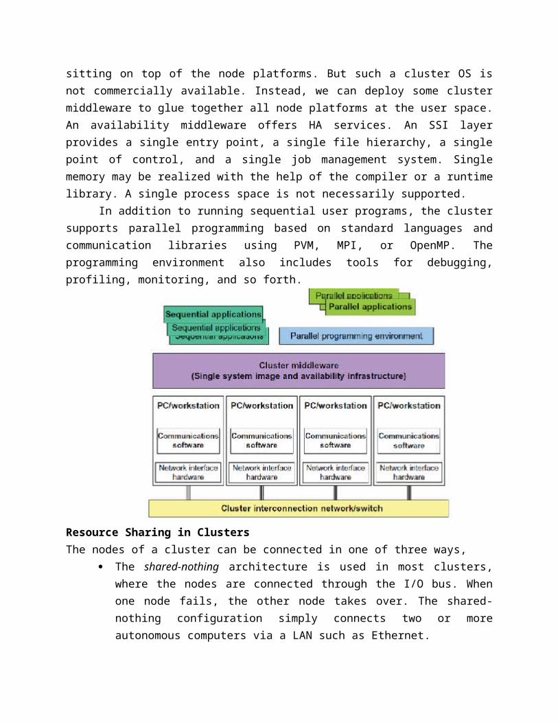
LSF supports most UNIX platforms and uses the standard IP for JMS communication. Because of this, it can convert a heterogeneous network of UNIX computers into a cluster. There is no need to change the underlying OS kernel. The end user utilizes the LSF functionalities through a set of utility commands. PVM and MPI are supported. Both a command-line interface and a GUI are pro-vided. LSF also offers skilled users an API that is a runtime library called LSLIB (load sharing library). Using LSLIB explicitly requires the user to modify the application code, whereas using the utility commands does not. Two LSF daemons are used on each server in the cluster. The load information managers (LIMs) periodically exchange load information. The remote execution server (RES) executes remote tasks.LSF Utility Commands
A cluster node may be a single-processor host or an SMP node with multiple processors, but always runs with only a single copy of the operating system on the node. Here are interesting features built into the LSF facilities:
• LSF supports all four combinations of interactive, batch, sequential, and parallel jobs. A job that is not executed through LSF is called a foreign job. A server node is one which can execute LSF jobs. A client node is one that can initiate or submit LSF jobs but cannot execute them. Only the resources on the server nodes can be shared. Server nodes can also initiate or submit LSF jobs.
• LSF offers a set of tools (lstools) to get information from LSF and to run jobs remotely. For instance, lshosts lists the static resources (discussed shortly) of every server node in the cluster. The command lsrun executes a program on a remote node.
• When a user types the command line %lsrun-R ‘swp>100’ myjob at a client node, the application myjob will be automatically executed on the most lightly loaded server node that has an available swap space greater than 100 MB.
• The lsbatch utility allows users to submit, monitor, and execute batch jobs through LSF. This utility is a load-sharing version of the popular UNIX command interpreter tcsh. Once a user enters the lstcsh shell, every command issued will be automatically executed on a suitable node.This is done transparently: The user sees a shell exactly like a tcsh running on the local node.
• The lsmake utility is a parallel version of the UNIX make utility, allowing a make file to be processed in multiple nodes simultaneously.
1.2.5 Case Studies of Top Supercomputer SystemsThis section reviews three top supercomputers that have been singled out as winners in
the Top 500 List for the years 2008–2010. The IBM Roadrunner was the world’s first petaflops computer, ranked No. 1in 1004. Subsequently, the Cray XT1 Jaguar became the top system in 2009. In November 2010, China’s Tianhe-1A became the fastest system in the world. All three systems are Linux cluster-structured with massive parallelism in term of large number of compute nodes that can execute concurrently.1.2.5.1 Tianhe-1A: The World Fastest Supercomputer in 2010
In November 2010, the Tianhe-1A was unveiled as a hybrid supercomputer at the 2010
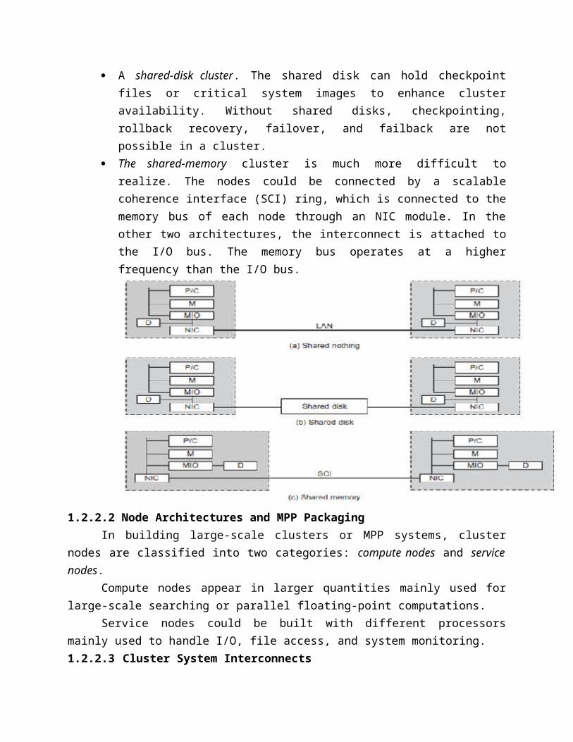
ACM Supercomputing Conference. This system demonstrated a sustained speed of 1.63 Pflops in Linpack Benchmark testing runs and thus became the No. 1 supercomputer in the 2010 Top 500 list. The system was built by the National University of Defense Technology (NUDT) and was installed in August 2010 at the National Supercomputer Center (NSC), Tianjin, in northern China the system is intended as an open platform for research and education. Architecture of Tianhe-1A The system consists of five major components. The compute subsystem houses all the CPUs and GPUs on 7,168 compute nodes. The service subsystem comprises eight operation nodes. The storage subsystem has a large number of shared disks. The monitoring and diagnosis subsystem is used for control and I/O operations. The communication subsystem is composed of switches for connecting to all functional subsystems.Hardware Implementation
This system is equipped with 14,336 six-core Xeon E5540/E5450 processors running 2.93 GHz with 7,168 NVIDIA Tesla M2050s. It has 7,168 compute nodes, each composed of two Intel Xeon5670 (Westmere) processors at 2.93 GHz, six cores per socket, and one NVIDIA M2050 GPUARCH Fat-Tree Interconnect
The high performance of the Tianhe-1A is attributed to a customed-designed ARCH interconnect by the NUDT builder. This ARCH is built with the InfiniBand DDR 4X and 98 TB of memory. It assumes a fat-tree architecture. The bidirectional bandwidth is 160 Gbps, about twice the bandwidth of the QDR InfiniBand network over the same number of nodes. The ARCH has a latency for a node hop of 1.57 microseconds, and an aggregated bandwidth of 61 Tb/second. At the first stage of the ARCH fat tree, 16 nodes are connected by a 16-port switching board. At the second stage, all parts are connects to eleven 384-port switches. The router and net-work interface chips are designed by the NUDT team.Software Stack
The software stack on the Tianhe-1A is typical of any high-performance system. It uses Kylin Linux, an operating system developed by NUDT and successfully approved by China’s 413 Hi-tech Research and Development Program office in 2006. Kylin is based on Mach and FreeBSD, is compatible with other mainstream operating systems, and supports multiple microprocessors and computers of different structures. Kylin packages include standard open source and public packages, which have been brought on to one system for easy installation. 1.2.5.2 IBM Roadrunner: The Top Supercomputer in 2008
In 2008, the IBM Roadrunner was the first general-purpose computer system in the world to reach petaflops performance. The system has a Linpack performance of 1.456 Pflops and is installed at the Los Alamos National Laboratory (LANL) in New Mexico. Subsequently, Cray’s Jaguar topped the Roadrunner in late 2009. The system was used mainly to assess the decay of the U.S. nuclear arsenal. Processor Chip and Compute Blade Design
The Cell/B.E. processors provide extraordinary compute power that can be harnessed from a single multicore chip. The Cell/B.E. architecture supports a very broad range of
applications. The first implementation is a single-chip multiprocessor with nine processor Message-Passing Performance
The Roadrunner uses MPI APIs to communicate with the other Opteron processors the application is running on in a typical single-program, multiple-data (SPMD) fashion. The number of compute nodes used to run the application is determined at program launch. The MPI implementation of Roadrunner is based on the open source Open MPI Project, and therefore is standard MPI. In this regard, Roadrunner applications are similar to other typical MPI applications such as those that run on the IBM Blue Gene solution. Where Roadrunner differs in the sphere of application architecture is how its Cell/B.E. accelerators are employed. At any point in the application flow, the MPI application running on each Opteron can offload computationally complex logic to its subordinate Cell/B.E. processor.1.3 Virtual Machines and Virtualization of Clusters and Data Centers1.3.1 Implementation Levels of Virtualization
Virtualization is a computer architecture technology by which multiple virtual machines (VMs) are multiplexed in the same hardware machine. The purpose of a VM is to enhance resource sharing by many users and improve computer performance in terms of resource utilization and application flexibility. Hardware resources (CPU, memory, I/O devices, etc.) or software resources (operating system and software libraries) can be virtualized in various functional layers. 1.3.1.1 Levels of Virtualization Implementation
A traditional computer runs with a host operating system specially tailored for its hardware architecture, After virtualization, different user applications managed by their own operating systems (guest OS) can run on the same hardware, independent of the host OS. This is often done by adding additional software, called a virtualization layer as shown in This virtualization layer is known as hypervisor or virtual machine monitor (VMM). The VMs shown in the upper boxes, where applications run with their own guest OS over the virtualized CPU, memory, and I/O resources.
The main function of the software layer for virtualization is to virtualize the physical hardware of a host machine into virtual resources to be used by the VMs, exclusively.
This can be implemented at various operational levels. Common virtualization layers include the instruction set architecture (ISA) level, hardware level, operating system level, library support level, and application level
Instruction Set Architecture LevelAt the ISA level, virtualization is performed by emulating a given ISA by the ISA of the
host machine. For example, MIPS binary code can run on an x41-based host machine with the help of ISA emulation. With this approach, it is possible to run a large amount of legacy binary code written for various processors on any given new hardware host machine. Instruction set emulation leads to virtual ISAs created on any hardware machine.
The basic emulation method is through code interpretation. An interpreter program interprets the source instructions to target instructions one by one. One source instruction may require tens or hundreds of native target instructions to perform its function. Obviously, this process is relatively slow. For better performance, dynamic binary translation is desired. This approach translates basic blocks of dynamic source instructions to target instructions.
The basic blocks can also be extended to program traces or super blocks to increase translation efficiency. Instruction set emulation requires binary translation and optimization. A virtual instruction set architecture (V-ISA) thus requires adding a processor-specific software translation layer to the compiler.
Hardware Abstraction LevelHardware-level virtualization is performed right on top of the bare hardware. On the one
hand, this approach generates a virtual hardware environment for a VM. On the other hand, the process manages the underlying hardware through virtualization. The idea is to virtualize a computer’s resources, such as its processors, memory, and I/O devices. Operating System Level
This refers to an abstraction layer between traditional OS and user applications. OS-level virtualization creates isolated containers on a single physical server and the OS instances to utilize the hard-ware and software in data centers. The containers behave like real servers. OS-level virtualization is commonly used in creating virtual hosting environments to allocate hardware resources among large number of mutually distrusting users. It is also used, to a lesser extent, in consolidating server hardware by moving services on separate hosts into containers or VMs on one server. OS-level virtualization.Library Support Level
Most applications use APIs exported by user-level libraries rather than using lengthy system calls by the OS. Since most systems provide well-documented APIs, such an interface becomes another candidate for virtualization. Virtualization with library interfaces is possible by controlling the communication link between applications and the rest of a system through API hooks. The software tool WINE has implemented this approach to support Windows applications on top of UNIX hosts. Another example is the vCUDA which allows applications executing within VMs to leverage GPU hardware acceleration. User-Application Level
Virtualization at the application level virtualizes an application as a VM. On a traditional OS, an application often runs as a process. Therefore, application-level virtualization is also known as process-level virtualization.
The most popular approach is to deploy high level language (HLL) VMs. In this scenario, the virtualization layer sits as an application program on top of the operating system, and the layer exports an abstraction of a VM that can run programs written and compiled to a particular abstract machine definition. Any program written in the HLL and compiled for this VM will be able to run on it. The Microsoft .NET CLR and Java Virtual Machine (JVM) are two good examples of this class of VM.
Other forms of application-level virtualization are known as application isolation, application sandboxing, or application streaming. The process involves wrapping the application in a layer that is isolated from the host OS and other applications. The result is an application that is much easier to distribute and remove from user workstations. An example is the LANDesk application virtualization platform which deploys software applications as self-contained, exec files in an isolated environment without requiring installation, system modifications, or elevated security privileges.Relative Merits of Different ApproachesCompares the relative merits of implementing virtualization at various levels. The column headings correspond to four technical merits. “Higher Performance” and “Application Flexibility” are self-explanatory. “Implementation Complexity” implies the cost to implement that particular virtualization level. “Application Isolation” refers to the effort required to isolate resources committed to different VMs. Each row corresponds to a particular level of virtualization. The number of X’s in the cells reflects the advantage point of each implementation level. Five X’s implies the best case and one X implies the worst case. Overall, hardware and OS support will yield the highest performance. However, the hardware and application levels are also the most expensive to implement. User isolation is the most difficult to achieve. ISA implementation offers the best application flexibility.
1.3.1.2 VMM Design Requirements and ProvidersAs mentioned earlier, hardware-level virtualization inserts a layer between real hardware and traditional operating systems. This layer is commonly called the Virtual Machine Monitor (VMM) and it manages the hardware resources of a computing system. There are three requirements for a VMM:
First, a VMM should provide an environment for programs which is essentially identical
to the original machine. Second, programs run in this environment should show, at worst, only minor decreases
in speed. Third, a VMM should be in complete control of the system resources. Any program run
under a VMM should exhibit a function identical to that which it runs on the original machine directly.
Two possible exceptions in terms of differences are permitted with this requirement: differences caused by the availability of system resources and differences caused by timing dependencies.
Obviously, these two differences pertain to performance, while the function a VMM provides stays the same as that of a real machine. However, the identical environment requirement excludes the behavior of the usual time-sharing operating system from being classed as a VMM.
A VMM should demonstrate efficiency in using the VMs. Compared with a physical machine, no one prefers a VMM if its efficiency is too low. Traditional emulators and complete software interpreters (simulators) emulate each instruction by means of functions or macros. Such a method provides the most flexible solutions for VMMs. However, emulators or simulators are too slow to be used as real machines. To guarantee the efficiency of a VMM, a statistically dominant subset of the virtual processor’s instructions needs to be executed directly by the real processor, with no software intervention by the VMM
Complete control of these resources by a VMM includes the following aspects: (1) The VMM is responsible for allocating hardware resources for programs; (1) it is not possible for a program to access any resource not explicitly allocated to it; and (3) it is possible under certain circumstances for a VMM to regain control of resources already allocated. Not all processors satisfy these requirements for a VMM. A VMM is tightly related to the architectures of processors.
It is difficult to implement a VMM for some types of processors, such as the x86. Specific limitations include the inability to trap on some privileged instructions. If a processor is not designed to support virtualization primarily, it is necessary to modify the hardware to satisfy the three requirements for a VMM. This is known as hardware-assisted virtualization.1.3.1.3 Virtualization Support at the OS Level
With the help of VM technology, a new computing mode known as cloud computing is emerging. Cloud computing is transforming the computing landscape by shifting the hardware and staffing costs of managing a computational center to third parties, just like banks. However, cloud computing has at least two challenges.
The first is the ability to use a variable number of physical machines and VM instances depending on the needs of a problem. For example, a task may need only a single CPU during some phases of execution but may need hundreds of CPUs at other times.
The second challenge concerns the slow operation of instantiating new VMs. Currently, new VMs originate either as fresh boots or as replicates of a template VM, unaware of the current application state. Therefore, to better support cloud computing, a large amount of research and development should be done.
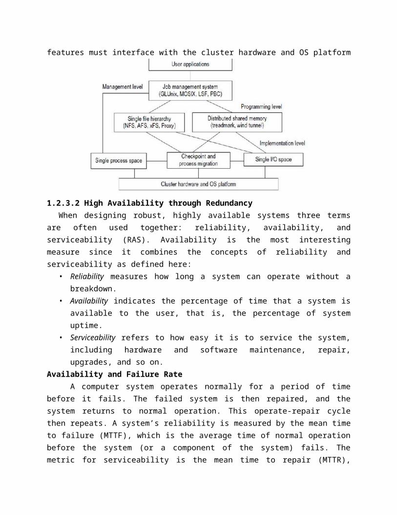
Why OS-Level Virtualization?To reduce the performance overhead of hardware-level virtualization, even hardware
modification is needed. OS-level virtualization provides a feasible solution for these hardware-level virtualization
issues. Operating system virtualization inserts a virtualization layer inside an operating system to partition a machine’s physical resources. It enables multiple isolated VMs within a single operating system kernel. This kind of VM is often called a virtual execution environment (VE), Virtual Private System (VPS), or simply container. From the user’s point of view, VEs look like real servers. This means a VE has its own set of processes, file system, user accounts, network interfaces with IP addresses, routing s, firewall rules, and other personal settings. Although VEs can be customized for different people, they share the same operating system kernel.
Therefore, OS-level virtualization is also called single-OS image virtualization. Operating system virtualization from the point of view of a machine stack.Advantages of OS ExtensionsCompared to hardware-level virtualization, the benefits of OS extensions are twofold: (1) VMs at the operating system level have minimal startup/shutdown costs, low resource requirements, and high scalability; and (2) For an OS-level VM, it is possible for a VM and its host environment to synchronize state changes when necessary. These benefits can be achieved via two mechanisms of OS-level virtualization: (1) All OS-level VMs on the same physical machine share a single operating system kernel; and (2) The virtualization layer can be designed in a way that allows processes in VMs to access as many resources of the host machine as possible, but never to modify them. In cloud computing, the first and second benefits can be used to overcome the defects of slow initialization of VMs at the hardware level, and being unaware of the current application state, respectively.Disadvantages of OS Extensions
The main disadvantage of OS extensions is that all the VMs at operating system level on a single container must have the same kind of guest operating system. That is, although different OS-level VMs may have different operating system distributions, they must pertain to the same operating system family. For example, a Windows distribution such as Windows XP cannot run on a Linux-based container. Virtualization on Linux or Windows Platforms
By far, most reported OS-level virtualization systems are Linux-based. Virtualization support on the Windows-based platform is still in the research stage. The Linux kernel offers an abstraction layer to allow software processes to work with and operate on resources without knowing the hardware details. New hardware may need a new Linux kernel to support. Therefore, different Linux platforms use patched kernels to provide special support for extended functionality. However, most Linux platforms are not tied to a special kernel. In such a case, a host can run several VMs simultaneously on the same hardware. Middleware Support for Virtualization
Library-level virtualization is also known as user-level Application Binary Interface
(ABI) or API emulation. This type of virtualization can create execution environments for running alien programs on a platform rather than creating a VM to run the entire operating system. API call interception and remapping are the key functions performed. 1.3.2 Virtualization Structures/Tools and Mechanisms1.3.2.1 Hypervisor and Xen Architecture
The hypervisor supports hardware-level virtualization on bare metal devices like CPU, memory, disk and network interfaces. The hypervisor software sits directly between the physical hardware and its OS. This virtualization layer is referred to as either the VMM or the hypervisor.
The hypervisor provides hypercalls for the guest OSes and applications. Depending on the functionality, a hypervisor can assume a micro-kernel architecture like the Microsoft Hyper-V. Or it can assume a monolithic hypervisor architecture like the VMware ESX for server virtualization.
A micro-kernel hypervisor includes only the basic and unchanging functions (such as physical memory management and processor scheduling). The device drivers and other changeable components are outside the hypervisor. A monolithic hypervisor implements all the aforementioned functions, including those of the device drivers. Therefore, the size of the hypervisor code of a micro-kernel hyper-visor is smaller than that of a monolithic hypervisor. Essentially, a hypervisor must be able to convert physical devices into virtual resources dedicated for the deployed VM to use.3.2.1.1 The Xen Architecture
Xen is an open source hypervisor program developed by Cambridge University. Xen is a micro-kernel hypervisor, which separates the policy from the mechanism. The Xen hypervisor implements all the mechanisms, leaving the policy to be handled by Domain 0. Xen does not include any device drivers natively. It just provides a mechanism by which a guest OS can have direct access to the physical devices. As a result, the size of the Xen hypervisor is kept rather small. Xen provides a virtual environment located between the hardware and the OS.A number of vendors are in the process of developing commercial Xen hypervisors, among them are Citrix XenServer and Oracle VM.
The core components of a Xen system are the hypervisor, kernel, and applications. The organization of the three components is important.
3.2.1.2 Binary Translation with Full VirtualizationDepending on implementation technologies, hardware virtualization can be classified into
two categories: full virtualization and host-based virtualization. Full virtualization does not need to modify the host OS. It relies on binary translation to
trap and to virtualize the execution of certain sensitive, nonvirtualizable instructions. The guest OSes and their applications consist of noncritical and critical instructions. In a host-based system, both a host OS and a guest OS are used. A virtualization software layer is built between the host OS and guest OS. Full Virtualization
With full virtualization, noncritical instructions run on the hardware directly while critical instructions are discovered and replaced with traps into the VMM to be emulated by software. Both the hypervisor and VMM approaches are considered full virtualization. Why are only critical instructions trapped into the VMM? This is because binary translation can incur a large performance overhead. Noncritical instructions do not control hardware or threaten the security of the system, but critical instructions do. Therefore, running noncritical instructions on hardware not only can promote efficiency, but also can ensure system security.Binary Translation of Guest OS Requests Using a VMM
This approach was implemented by VMware and many other software companies. As shown in figure VMware puts the VMM at Ring 0 and the guest OS at Ring 1. The VMM scans the instruction stream and identifies the privileged, control- and behavior-sensitive instructions. When these instructions are identified, they are trapped into the VMM, which emulates the behavior of these instructions. The method used in this emulation is called binary translation. Therefore, full virtualization combines binary translation and direct execution. The guest OS is completely decoupled from the underlying hardware. Consequently, the guest OS is unaware that it is being virtualized.
Binary translation employs a code cache to store translated hot instructions to improve performance, but it increases the cost of memory usage. Host-Based Virtualization
An alternative VM architecture is to install a virtualization layer on top of the host OS. This host OS is still responsible for managing the hardware. The guest OSes are installed and run on top of the virtualization layer. Dedicated applications may run on the VMs.
3.2.1.3 Para-Virtualization with Compiler SupportPara-virtualization needs to modify the guest operating systems. A para-virtualized VM provides special APIs requiring substantial OS modifications in user applications. Performance degradation is a critical issue of a virtualized system. No one wants to use a VM if it is much slower than using a physical machine. The virtualization layer can be inserted at different positions in a machine soft-ware stack. However, para-virtualization attempts to reduce the virtualization overhead, and thus improve performance by modifying only the guest OS kernel.Following figure illustrates the concept of a para-virtualized VM architecture. The guest operating systems are para-virtualized. They are assisted by an intelligent compiler to replace the nonvirtualizable OS instructions by hypercalls. The traditional x86 processor offers four instruction execution rings: Rings 0, 1, 1, and 3. the lower the ring number, the higher the privilege of instruction being executed. The OS is responsible for managing the hardware and the privileged instructions to execute at Ring 0, while user-level applications run at Ring 3. The best example of para-virtualization is the KVM to be described below.
Para-Virtualization ArchitectureWhen the x86 processor is virtualized, a virtualization layer is inserted between the
hardware and the OS. According to the x86 ring definition, the virtualization layer should also be installed at Ring 0. Different instructions at Ring 0 may cause some problems. The para-virtualization replaces nonvirtualizable instructions with hypercalls that communicate directly with the hypervisor or VMM. However, when the guest OS kernel is modified for virtualization, it can no longer run on the hardware directly. Although para-virtualization reduces the overhead, it has incurred other problems.
First, its compatibility and portability may be in doubt, because it must support the unmodified OS as well.
Second, the cost of maintaining para-virtualized OSes is high, because they may require deep OS kernel modifications.
Finally, the performance advantage of para-virtualization varies greatly due to workload variations. Compared with full virtualization, para-virtualization is relatively easy and more practical.
The main problem in full virtualization is its low performance in binary translation. To speed up binary translation is difficult. Therefore, many virtualization products employ the para-virtualization architecture. The popular Xen, KVM, and VMware ESXare good examples.KVM (Kernel-Based VM)
This is a Linux para-virtualization system a part of the Linux version 2.6.20 kernel. Memory management and scheduling activities are carried out by the existing Linux kernel. The KVM does the rest, which makes it simpler than the hypervisor that controls the entire machine. KVM is a hardware-assisted para-virtualization tool, which improves performance and supports unmodified guest OSes such as Windows, Linux, Solaris, and other UNIX variants.Para-Virtualization with Compiler Support
Unlike the full virtualization architecture which intercepts and emulates privileged and sensitive instructions at runtime, para-virtualization handles these instructions at compile time. The guest OS kernel is modified to replace the privileged and sensitive instructions with hypercalls to the hypervisor or VMM. Xen assumes such a para-virtualization architecture.
The guest OS running in a guest domain may run at Ring 1 instead of at Ring 0. This implies that the guest OS may not be able to execute some privileged and sensitive instructions. The privileged instructions are implemented by hypercalls to the hypervisor. After replacing the instructions with hypercalls, the modified guest OS emulates the behavior of the original guest OS. On a UNIXsystem, a system call involves an interrupt or service routine. The hypercalls apply a dedicated service routine in Xen.1.3.3 Virtualization of CPU, Memory, and I/O Devices
To support virtualization, processors such as the x41 employ a special running mode and instructions, known as hardware-assisted virtualization. In this way, the VMM and guest OS run in different modes and all sensitive instructions of the guest OS and its applications are trapped in the VMM. 1.3.3.1 Hardware Support for Virtualization
Modern operating systems and processors permit multiple processes to run simultaneously. If there is no protection mechanism in a processor, all instructions from different processes will access the hardware directly and cause a system crash. Therefore, all processors have at least two modes, user mode and supervisor mode, to ensure controlled access of critical hardware. Instructions running in supervisor mode are called privileged instructions. Other instructions are unprivileged instructions. In a virtualized environment, it is more difficult to make OSes and applications run correctly because there are more layers in the machine stack 1.3.3.2 CPU Virtualization
A VM is a duplicate of an existing computer system in which a majority of the VM instructions are executed on the host processor in native mode. Thus, unprivileged instructions of VMs run directly on the host machine for higher efficiency. Other critical instructions should be handled carefully for correctness and stability. The critical instructions are divided into three categories: privileged instructions, control-sensitive instructions, and behavior-sensitive instructions. Privileged instructions execute in a privileged mode and will be trapped if executed outside this mode. Control-sensitive instructions attempt to change the configuration of resources used. Behavior-sensitive instructions have different behaviors depending on the configuration of resources, including the load and store operations over the virtual memory.
A CPU architecture is virtualizable if it supports the ability to run the VM’s privileged
and unprivileged instructions in the CPU’s user mode while the VMM runs in supervisor mode. When the privileged instructions including control- and behavior-sensitive instructions of a VM are executed, they are trapped in the VMM. In this case, the VMM acts as a unified mediator for hardware access from different VMs to guarantee the correctness and stability of the whole system. However, not all CPU architectures are virtualizable. RISC CPU architectures can be naturally virtualized because all control- and behavior-sensitive instructions are privileged instructions. On the contrary, x86 CPU architectures are not primarily designed to support virtualization. This is because about 10 sensitive instructions, such as SGDT and SMSW, are not privileged instructions. When these instructions execute in virtualization, they cannot be trapped in the VMM. Hardware-Assisted CPU Virtualization
This technique attempts to simplify virtualization because full or paravirtualization is complicated. Intel and AMD add an additional mode called privilege mode level (some people call it Ring-1) to x86 processors. Therefore, operating systems can still run at Ring 0 and the hypervisor can run at Ring -1. All the privileged and sensitive instructions are trapped in the hypervisor automatically. This technique removes the difficulty of implementing binary translation of full virtualization. It also lets the operating system run in VMs without modification.1.3.3.3 Memory Virtualization
Virtual memory virtualization is similar to the virtual memory support provided by modern operating systems. In a traditional execution environment, the operating system maintains mappings of virtual memory to machine memory using page s, which is a one-stage mapping from virtual memory to machine memory. All modern x41 CPUs include a memory management unit (MMU) and a translation look aside buffer (TLB) to optimize virtual memory performance. However, in a virtual execution environment, virtual memory virtualization involves sharing the physical system memory in RAM and dynamically allocating it to the physical memory of the VMs.
That means a two-stage mapping process should be maintained by the guest OS and the VMM, respectively: virtual memory to physical memory and physical memory to machine memory. The guest OS continues to control the mapping of virtual addresses to the physical memory addresses of VMs. But the guest OS cannot directly access the actual machine memory. The VMM is responsible for mapping the guest physical memory to the actual machine memory. The two-level memory mapping procedure. Since each page of the guest OSes has a separate page in the VMM corresponding to it, the VMM page is called the shadow page. Nested pages add another layer of indirection to virtual memory.
The AMD Barcelona processor has featured hardware-assisted memory virtualization since 2007. It provides hardware assistance to the two-stage address translation in a virtual execution environment by using a technology called nested paging.1.3.3.4 I/O Virtualization
I/O virtualization involves managing the routing of I/O requests between virtual devices and the shared physical hardware. At the time of this writing, there are three ways to implement
I/O virtualization: full device emulation, para-virtualization, and direct I/O. Full device emulation is the first approach for I/O virtualization. Generally, this approach emulates well-known, real-world devices. All the functions of a device or bus infrastructure, such as device enumeration, identification, interrupts, and DMA, are replicated in software. This software is located in the VMM and acts as a virtual device.
The I/O access requests of the guest OS are trapped in the VMM which interacts with the I/O devices. The full device emulation approach is shown.
A single hardware device can be shared by multiple VMs that run concurrently. However, software emulation runs much slower than the hardware it emulates. The para-virtualization method of I/O virtualization is typically used in Xen. It is also known as the split driver model consisting of a frontend driver and a backend driver. The frontend driver is running in Domain U and the backend driver is running in Domain 0. They interact with each other via a block of shared memory. The frontend driver manages the I/O requests of the guest OSes and the backend driver is responsible for managing the real I/O devices and multiplexing the I/O data of different VMs. Although para-I/O-virtualization achieves better device performance than full device emulation, it comes with a higher CPU overhead.
Direct I/O virtualization lets the VM access devices directly. It can achieve close-to-native performance without high CPU costs. However, current direct I/O virtualization implementations focus on networking for mainframes. There are a lot of challenges for commodity hardware devices.
Another way to help I/O virtualization is via self-virtualized I/O (SV-IO). The key idea of SV-IO is to harness the rich resources of a multicore processor.
The guest OS interacts with the VIFs via VIF device drivers. Each VIF consists of two message queues. One is for outgoing messages to the devices and the other is for incoming messages from the devices. In addition, each VIF has a unique ID for identifying it in SV-IO.1.3.3.5 Virtualization in Multi-Core Processors
Virtualizing a multi-core processor is relatively more complicated than virtualizing a unicore processor. Though multicore processors are claimed to have higher performance by integrating multiple processor cores in a single chip, multicore virtualization has raised some new challenges to computer architects, compiler constructors, system designers, and application programmers.
There are mainly two difficulties: 1. Application programs must be parallelized to use all cores fully, and software must
explicitly assign tasks to the cores, which is a very complex problem. Concerning the first challenge, new programming models, languages, and libraries are needed to make parallel programming easier.
2. The second challenge has spawned research involving scheduling algorithms and resource management policies. Yet these efforts cannot balance well among performance, complexity, and other issues. What is worse, as technology scales, a new challenge called dynamic heterogeneity is emerging to mix the fat CPU core and thin GPU cores on the same chip, which further complicates the multi-core or many-core resource management.
1.3.4 Virtual Clusters and Resource ManagementA physical cluster is a collection of servers (physical machines) interconnected by a
physical network such as a LAN. Here, we introduce virtual clusters and study its properties as well as explore their potential applications. In this section, we will study three critical design issues of virtual clusters: live migration of VMs, memory and file migrations, and dynamic deployment of virtual clusters. 1.3.4.1 Physical versus Virtual ClustersVirtual clusters are built with VMs installed at distributed servers from one or more physical clusters. The VMs in a virtual cluster are interconnected logically by a virtual network across several physical networks. Each virtual cluster is formed with physical machines or a VM hosted by multiple physical clusters. The virtual cluster boundaries are shown as distinct boundaries. The provisioning of VMs to a virtual cluster is done dynamically to have the following interesting properties:
The virtual cluster nodes can be either physical or virtual machines. Multiple VMs running with different OSes can be deployed on the same physical node.
A VM runs with a guest OS, which is often different from the host OS, that manages the resources in the physical machine, where the VM is implemented.
VMs can be colonized (replicated) in multiple servers for the purpose of promoting distributed parallelism, fault tolerance, and disaster recovery.
The size (number of nodes) of a virtual cluster can grow or shrink dynamically, similar to the way an overlay network varies in size in a peer-to-peer (P2P) network.
The failure of any physical nodes may disable some VMs installed on the failing nodes. But the failure of VMs will not pull down the host system.
Since system virtualization has been widely used, it is necessary to effectively manage VMs running on a mass of physical computing nodes (also called virtual clusters) and consequently build a high-performance virtualized computing environment. Fast Deployment and Effective Scheduling
The system should have the capability of fast deployment. Here, deployment means two things: to construct and distribute software stacks (OS, libraries, applications) to a physical node inside clusters as fast as possible, and to quickly switch runtime environments from one user’s virtual cluster to another user’s virtual cluster. If one user finishes using his system, the corresponding virtual cluster should shut down or suspend quickly to save the resources to run other VMs for other users.
The concept of “green computing” has attracted much attention recently. The live migration of VMs allows workloads of one node to transfer to another node. However, it does not guarantee that VMs can randomly migrate among themselves. In fact, the potential overhead caused by live migrations of VMs cannot be ignored.
The overhead may have serious negative effects on cluster utilization, throughput, and QoS issues. Therefore, the challenge is to determine how to design migration strategies to implement green computing without influencing the performance of clusters.
Another advantage of virtualization is load balancing of applications in a virtual cluster. Load balancing can be achieved using the load index and frequency of user logins. The automatic scale-up and scale-down mechanism of a virtual cluster can be implemented based on this model. Consequently, we can increase the resource utilization of nodes and shorten the response time of systems. Mapping VMs onto the most appropriate physical node should promote performance. Dynamically adjusting loads among nodes by live migration of VMs is desired, when the loads on cluster nodes become quite unbalanced.High-Performance Virtual Storage
The template VM can be distributed to several physical hosts in the cluster to customize the VMs. In addition, existing software packages reduce the time for customization as well as switching virtual environments. It is important to efficiently manage the disk spaces occupied by template software packages. Some storage architecture design can be applied to reduce duplicated blocks in a distributed file system of virtual clusters. Hash values are used to compare the contents of data blocks. Users have their own profiles which store the identification of the data blocks for corresponding VMs in a user-specific virtual cluster. New blocks are created when users modify the corresponding data. Newly created blocks are identified in the users’ profiles. Basically, there are four steps to deploy a group of VMs onto a target cluster: Preparing the disk image, Configuring the VMs, Choosing the destination nodes, and Executing the VM deployment command on every host.
Many systems use templates to simplify the disk image preparation process. A template is a disk image that includes a preinstalled operating system with or without certain application software. Users choose a proper template according to their requirements and make a duplicate of it as their own disk image. Templates could implement the COW (Copy on Write) format. A new COW backup file is very small and easy to create and transfer. Therefore, it definitely reduces disk space consumption. In addition, VM deployment time is much shorter than that of copying the whole raw image file.
Every VM is configured with a name, disk image, network setting, and allocated CPU and memory. One needs to record each VM configuration into a file. However, this method is inefficient when managing a large group of VMs. VMs with the same configurations could use predicted profiles to simplify the process. In this scenario, the system cons the VMs according to the chosen pro-file. Most configuration items use the same settings, while some of them, such as UUID, VM name, and IP address, are assigned with automatically calculated values. Normally, users do not care which host is running their VM. A strategy to choose the proper destination host for any VM is needed. The deployment principle is to fulfill the VM requirement and to balance workloads among the whole host network.1.3.4.2 Live VM Migration Steps and Performance Effects
In a cluster built with mixed nodes of host and guest systems, the normal method of operation is to run everything on the physical machine. When a VM fails, its role could be replaced by another VM on a different node, as long as they both run with the same guest OS. In other words, a physical node can fail over to a VM on another host. This is different from physical-to-physical failover in a traditional physical cluster. The advantage is enhanced failover flexibility. The potential drawback is that a VM must stop playing its role if its residing host node fails. However, this problem can be mitigated with VM life migration. Following figure shows the process of life migration of a VM from host A to host B. The migration copies the VM state file from the storage area to the host machine. There are four ways to manage a virtual cluster.
First, you can use a guest-based manager, by which the cluster manager resides on a guest system.
Second, you can build a cluster manager on the host systems. The host-based manager supervises the guest systems and can restart the guest system on another physical machine
A third way to manage a virtual cluster is to use an independent cluster manager on both the host and guest systems. This will make infrastructure management more complex, however.
Finally, you can use an integrated cluster on the guest and host systems. This means the manager must be designed to distinguish between virtualized resources and physical resources.
VMs can be live-migrated from one physical machine to another; in case of failure, one VM can be replaced by another VM. The motivation is to design a live VM migration scheme with negligible downtime, the lowest network bandwidth consumption possible, and a reasonable total migration time.
As shown in figure, live migration of a VM consists of the following six steps:Steps 0 and 1: Start migration. This step makes preparations for the migration, including
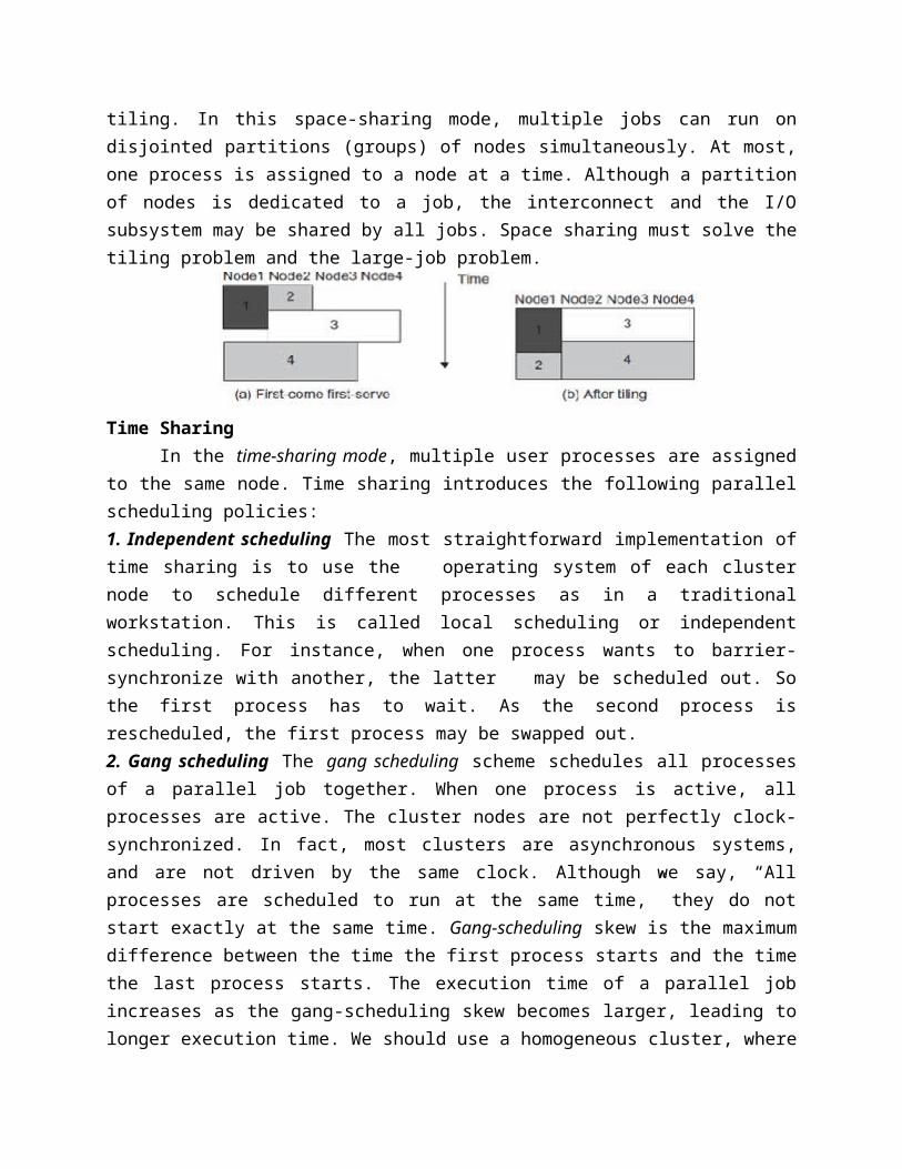
determining the migrating VM and the destination host. Although users could manually make a VM migrate to an appointed host, in most circumstances, the migration is automatically started by strategies such as load balancing and server consolidation.
Steps 1: Transfer memory. Since the whole execution state of the VM is stored in memory, sending the VM’s memory to the destination node ensures continuity of the service provided by the VM. All of the memory data is transferred in the first round, and then the migration controller recopies the memory data which is changed in the last round. These steps keep iterating until the dirty portion of the memory is small enough to handle the final copy. Although precopying memory is performed iteratively, the execution of programs is not obviously interrupted.Step 3: Suspend the VM and copy the last portion of the data . The migrating VM’s execution is suspended when the last round’s memory data is transferred. Other nonmemory data such as CPU and network states should be sent as well. During this step, the VM is stopped and its applications will no longer run. This “service unavailable” time is called the “downtime” of migration, which should be as short as possible so that it can be negligible to users.Steps 4 and 1: Commit and activate the new host. After all the needed data is copied, on the destination host, the VM reloads the states and recovers the execution of programs in it, and the service provided by this VM continues. Then the network connection is redirected to the new VM and the dependency to the source host is cleared. The whole migration process finishes by removing the original VM from the source host. 1.3.4.3 Migration of Memory, Files, and Network Resources
When one system migrates to another physical node, we should consider the following issues.Memory Migration
This is one of the most important aspects of VM migration. Moving the memory instance of a VM from one physical host to another can be approached in any number of ways.
Memory migration can be in a range of hundreds of megabytes to a few gigabytes in a
typical system today, and it needs to be done in an efficient manner. The Internet Suspend-Resume (ISR) technique exploits temporal locality as memory
states are likely to have considerable overlap in the suspended and the resumed instances of a VM. Temporal locality refers to the fact that the memory states differ only by the amount of work done since a VM was last suspended before being initiated for migration.
To exploit temporal locality, each file in the file system is represented as a tree of small sub files. A copy of this tree exists in both the suspended and resumed VM instances. The advantage of using tree-based representation of files is that the caching ensures the transmission of only those files which have been changed. File System Migration
To support VM migration, a system must provide each VM with a consistent, location-independent view of the file system that is available on all hosts. A simple way to achieve this is to provide each VM with its own virtual disk which the file system is mapped to and transport the contents of this virtual disk along with the other states of the VM. However, due to the current trend of high-capacity disks, migration of the contents of an entire disk over a network is not a viable solution. Another way is to have a global file system across all machines where a VM could be located. This way removes the need to copy files from one machine to another because all files are network-accessible. Network Migration
A migrating VM should maintain all open network connections without relying on forwarding mechanisms on the original host or on support from mobility or redirection mechanisms. To enable remote systems to locate and communicate with a VM, each VM must be assigned a virtual IP address known to other entities. This address can be distinct from the IP address of the host machine where the VM is currently located. Each VM can also have its own distinct virtual MAC address. The VMM maintains a mapping of the virtual IP and MAC addresses to their corresponding VMs. In general, a migrating VM includes all the protocol states and carries its IP address with it.
If the source and destination machines of a VM migration are typically connected to a single switched LAN, an unsolicited ARP reply from the migrating host is provided advertising that the IP has moved to a new location. This solves the open network connection problem by reconfiguring all the peers to send future packets to a new location. Although a few packets that have already been transmitted might be lost, there are no other problems with this mechanism.
Traditional migration suspends VMs before the transportation and then resumes them at the end of the process. By importing the pre copy mechanism, a VM could be live-migrated without stopping the VM and keep the applications running during the migration. Live Migration of VM Using Xen We studied Xen as a VMM or hypervisor, which allows multiple commodity OSes to share x86 hardware in a safe and orderly fashion. The following example explains how to perform live migration of a VM between two Xen-enabled host machines. Domain 0 (or Dom0) performs tasks to create, terminate, or migrate to another host. Xen uses a send/recv model to transfer states across VMs.
1.3.5 Virtualization for Data-Center AutomationData-center automation means that huge volumes of hardware, software, and database
resources in these data centers can be allocated dynamically to millions of Internet users simultaneously, with guaranteed QoS and cost-effectiveness. 1.3.5.1 Server Consolidation in Data Centers
In data centers, a large number of heterogeneous workloads can run on servers at various times. These heterogeneous workloads can be roughly divided into two categories: chatty workloads and non-inter-active workloads.
Chatty workloads may burst at some point and return to a silent state at some other point. A web video service is an example of this, whereby a lot of people use it at night and few people use it during the day.
Non interactive workloads do not require people’s efforts to make progress after they are submitted. High-performance computing is a typical example of this. Therefore, it is common that most servers in data centers are underutilized. A large amount of hardware, space, power, and management cost of these servers is wasted. Data centers need to optimize their resource management. Yet these techniques are performed with the granularity of a full server machine, which makes resource management far from well optimized. Server virtualization enables smaller resource allocation than a physical machine. In general, the use of VMs increases resource management complexity. This causes a challenge in terms of how to improve resource utilization as well as guarantee QoS in data centers. In detail, server virtualization has the following side effects:
Consolidation enhances hardware utilization. Many underutilized servers are consolidated into fewer servers to enhance resource utilization. Consolidation also facilitates backup services and disaster recovery.
The total cost of ownership is reduced. This approach improves availability and business continuity. The crash of a guest OS has no effect on the host OS or any other guest OS. It becomes easier to transfer a VM from one server to another, because virtual servers are unaware of the underlying hardware.
To automate data-center operations, one must consider resource scheduling, architectural support, power management, automatic or autonomic resource management, performance of analytical models, and so on. 1.3.5.2 Virtual Storage Management
The term “storage virtualization” was widely used before the renaissance of system virtualization. Yet the term has a different meaning in a system virtualization environment. Previously, storage virtualization was largely used to describe the aggregation and repartitioning of disks at very coarse time scales for use by physical machines. In system virtualization, virtual storage includes the storage managed by VMMs and guest OSes.
Generally, the data stored in this environment can be classified into two categories: VM images and application data. The VM images are special to the virtual environment, while application data includes all other data which is the same as the data in traditional OS
environments. 1.3.5.3 Cloud OS for Virtualized Data Centers
Data centers must be virtualized to serve as cloud providers. Four virtual infrastructure (VI) managers and OSes. These VI managers and OSes are specially tailored for virtualizing data centers which often own a large number of servers in clusters. Nimbus, Eucalyptus, and OpenNebula are all open source software available to the general public. Only vSphere 4 is a proprietary OS for cloud resource virtualization and management over data centers. These VI managers are used to create VMs and aggregate them into virtual clusters as elastic resources. Nimbus and Eucalyptus support essentially virtual networks. OpenNebula has additional features to provision dynamic resources and make advance reservations1.3.5.4 Trust Management in Virtualized Data Centers
A VMM changes the computer architecture. It provides a layer of software between the operating systems and system hardware to create one or more VMs on a single physical platform. A VM entirely encapsulates the state of the guest operating system running inside it. Encapsulated machine state can be copied and shared over the network and removed like a normal file, which proposes a challenge to VM security. In general, a VMM can provide secure isolation and a VM accesses hard-ware resources through the control of the VMM, so the VMM is the base of the security of a virtual system. Normally, one VM is taken as a management VM to have some privileges such as creating, suspending, resuming, or deleting a VM.
Once a hacker successfully enters the VMM or management VM, the whole system is in danger. A subtler problem arises in protocols that rely on the “freshness” of their random number source for generating session keys. Considering a VM, rolling back to a point after a random number has been chosen, but before it has been used, resumes execution; the random number, which must be “fresh” for security purposes, is reused. With a stream cipher, two different plaintexts could be encrypted under the same key stream, which could, in turn, expose both plaintexts if the plaintexts have sufficient redundancy. Non cryptographic protocols that rely on freshness are also at risk. For example, the reuse of TCP initial sequence numbers can raise TCP hijacking attacksVM-Based Intrusion Detection
Intrusions are unauthorized access to a certain computer from local or network users and intrusion detection is used to recognize the unauthorized access. An intrusion detection system (IDS) is built on operating systems, and is based on the characteristics of intrusion actions. A typical IDS can be classified as a host-based IDS (HIDS) or a network-based IDS (NIDS), depending on the data source. A HIDS can be implemented on the monitored system. When the monitored system is attacked by hackers, the HIDS also faces the risk of being attacked. A NIDS is based on the flow of network traffic which can’t detect fake actions.
Virtualization-based intrusion detection can isolate guest VMs on the same hardware platform. There are two different methods for implementing a VM-based IDS: Either the IDS is an independent process in each VM or a high-privileged VM on the VMM; or the IDS is integrated into the VMM.
Unit-I Important Questions1. Write about distributed system models and enabling technologies 2. Explain in detail about system models and distributed cloud computing 3. Explain about Design Principles of Computer Clusters4. List out the design principles of computer clusters 5. Explain about Computer Clusters and MPP Architectures6. Write about technologies for network based system with suitable diagrams7. Write about Virtual Clusters and Resource Management 8. Explain the virtualization structure/Tools and mechanisms 9. What are the three computing paradigms for cloud computing? 10. Draw a neat graph for hype cycle for emerging technologies11. Sketch a three cloud service models in a cloud landscape of major providers 12. Explain in detail about evaluation of SOA 13 Explain about parallel and distributed programming models 14. Discuss GPU clusters for massive parallelism.