0 2 manual 8 4 digital 3-phase servo-drive s d 0 for ec/ac
TRANSCRIPT

MANUALDigital 3-phase Servo-Drive
DS2420, DS4820
for EC/AC servo motors
- Battery connection -
Version0211-V8
DS
242
0, D
S 4
820
Stegmaier-Haupt GmbH Industrieelektronik____________________________________________________________________________________________
Stegmaier-Haupt GmbHIndustrieelektronik-ServoantriebstechnikUntere Röte 5D-69231 RauenbergTel.: 06222-61021Fax: 06222-64988Email: [email protected]: // www.stegmaier-haupt.de

2
DS2420, DS4820
Conten t
Content
Part 1 Hardware manual Page1. Basic information1.1 Safety advice, standards and guidelines 3,41.2 General Information 51.3 Applications 61.4 Build, Features 71.5 Technical data 8,9
2. Mechanical installationImportant advice 11
2.1 Dimensions DS2420, DS4820 122.2 Dimensions accessories 132.3 Mounting 14
3. Electrical installationImportant advice 15
3.1 Circuit diagram 16,173.2 Connections EC/AC 183.3 Connectors DC 193.4 Connectors 203.5 Battery connection 213.6 Motor connection EC/AC 223.7 Motor connection DC 233.8 Control signals 24,253.9 Interfaces 26,273.10 Resolver 283.11 Encoder 293.12 Sin/Cos connection for DSxx-SC 303.13 Rotor position 313.14 X8 encoder - output-input 32,333.15 LED displays 343.16 Error message 353.17 Warning message 363.16 Options 37
Guarantee 38
Part 2 Software manual
Part 3 Commissioning instruction
Part 4 Software reference
Part 5 CAN-BUS reference
3
DS2420, DS4820
Electronic equipment is not fault proof. This fact should be borne in mind for all possibleoperating conditions.
Before installation or commissioning begins, this manual must be thoroughly read andunderstood by the technical staff involved.If any uncertainty arises, the manufacturer or dealer should be contacted.Any incorrect installation or assembly may damage or destroy the units.
DS xx devices are power electric parts used for regulating energy flows. They are designedfor the control of EC synchronous motors (brushless dc motors, BLDC) for industrialapplications and they are part of an electric drive (PDS).Protection rating IP20 for switch cabinet mounting.Connection only to an earthed ac or three-phase power supply.
Standards and guidelinesThe device and its associated components can only be installed and switched on where thelocal regulations and technical standards have been strictly adhered to:EU Guidelines 89/392/EWG, 84/528/EWG, 86/663/EWG, 72/23/EWG
EN60204, EN50178, EN60439-1, EN60146, EN61800-3IEC/UL IEC364, IEC 664, UL508C, UL840VDE Regulations VDE100, VDE110, VDE160TÜV RegulationsTrade body guidelines VGB4
The control and power connections may be voltage-carrying without the axis operating!The discharge time of the bus circuit is superior to 4 min!Measure the voltage before any disassembly!
Saf
ety
advi
ce
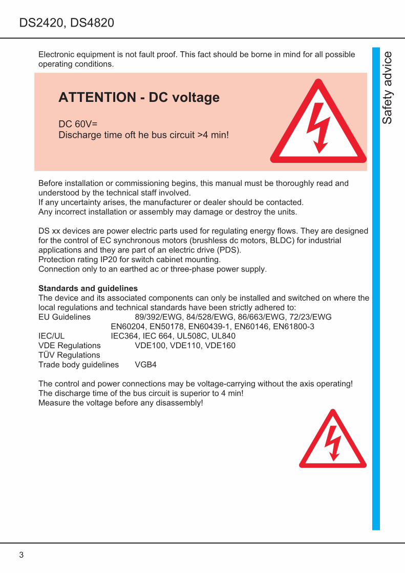
ATTENTION - DC voltage
DC 60V=Discharge time oft he bus circuit >4 min!

4
DS2420, DS4820
The user must ensure that in the event of:- device failure- incorrect operation- loss of regulation or controlthe axis will be safely de-activated.It must also be ensured that the machine or equipment arefitted with device independent monitoring and safety features.Man as well as property must not be exposed to danger atany time.
Assembly- should only be carried out when all voltages have been removed.- should only be carried out by suitably trained personnel.Installation
- should only be carried out when all voltages have been removed.- should only be carried out by suitably trained personnel- should only be carried outin accordance with health and safety
guidelinesSetting adjustments/programming
- should only be carried out by suitably trained personnel with knowledge in electronicdrives and their software- should only be carried out in accordance with the programming advice- should only be carried out in accordance with health and safety guidelinesCEAfter having been mounted in machines and installations the operation ofthe device mustnot be started until the machine or the installation has been approved ofthe regulations ofthe EC machine guideline 89/392/EWG and the EMC guideline 89/336/EWG.Under the installation and test conditions of chapter ‘EMC advice’ the device adheres to thefollowing: guideline EU89/336/EWG, EMC standards EN61000-2andEN61000-4.A manufacturer’s declaration can be asked for.
QSTest results are archived with the device serial number by the manufacturer for a period of5 years. Test protocols can be asked for.
Safety symbols
Caution - Danger to life AttentionHigh voltage Warning
Important
Safety a dvice
5
DS2420, DS4820
GeneralinformationThe digital 3-phase current servo amplifier DS xx in combination with the brushless dcmotor (synchro servo motor, CE motor) provide a drive solution free of maintenance andwith a wide dynamic control range. The drive displays the well-known good controlcharacteristics of dc drives without the disadvantages of the carbon brushes’ wear and thecommutation limits. The rotor moment of inertia is notably lower and the threshold power isgreater than with equally constructed dc motors. This results inup to 5 times higheracceleration values. Compared to asynchronous motors with frequency converters thestability, the control range and the efficiency of the drive are considerably improved. Thegenerated heat in the motor only occurs in the stator, therefore, the EC motors always havethe protection rating IP 65.From the electrical view, the brushless dc motor is a synchro motor with a permanentmagnet rotor and a three-phase current stator.The physical characteristics correspond to those of dc motors, i.e., the current isproportional to the torque and the voltage is proportional to the speed. The speed issteadily controlled up to the current limit (max. torque. In case of an overload the speeddrops and the current remains constant.The speed/torque characteristic is rectangular.Current, speed, and position are precisely measured. The field frequency is notcontrollable, it is automatically adjusted.The motor voltages and the motor currents are sinusoidal. A maximum motor efficiency isachieved by means of a compensating current control.The DS2420 drives can be used as single-axis position amplifier or torque or speedamplifier.The position and speed actual value is generated in the encoder unit (resolver orincremental encoder). The encoder pulses are emitted from the amplifier for asuperordinate PLC/CNC control. The control circuits of current, speed, and position are PIDcontrollers which are easy to program. They can be programmed by means of a PC or aprogramming box.The communication with superordinate controls is effected by means ofBUS systems (standard CAN-BUS,RS232) or by analogue interfaces.
Note:The energy is fed back into the battery during brake operation.No ballast (regen) circuit.For any operation via a mains supply circuit (without battery) a separate ballast circuit or avoltage watchdog must be installed.
Information:Digital servo-amplifiers > series DS200, DS400Analog three-phase servo-amplifiers > series TVD3, TVD6, ASAnalog dc servo-amplifiers > series TV3, TV6, TVQ6Thyristor current converters 1Q, 4Q, servo > series Classic, 200W to 800kW DC and ac servo-amplifiers for battery operation > series BAMO A2, A3, D3analog and digital series BAMOBIL
Gen
eral
info
rmat
ion
6
DS2420, DS4820
ApplicationsBattery-driven machines andi nstallations for all types with a drive power of 1kW especiallyas 4Q-servo-drive for- highly dynamic acceleration and braking cycles- a wide control range- a high efficiency- small motor dimensions- a uniform, accurate and smooth runningFor speed or torque control or combined speed/torque control incorporated within orindependent of position control loops.Drives with constant speed as in conveyors, spindle drives, pumps, transversal orlongitudinal pitch drives.Synchronous multiple motor drives.Synchro-servo-drives are more compact than other electric drives.
Particularly suitable for:component equipment inserting machines, testing machines, sheet-metal workingmachines,machine tools, plastic working machines, assembly machines,knitting and sewing machines, textile working machines, grinding machines,wood and stone working machines, metal working machines, food processing machines,robots and handling systems, conveyors, extruders, calenders, andmany other machines and installations.
Motor features- protection rating IP 65- compact- suitable for rough surroundings- suitable for high dynamic overload-free of maintenance
NoteBrushless drives are used where braking operations are predominant, e.g. whendeceleration is mainly required:- winding machines, lifts, great centrifugal masses, vehiclesThe braking energy is fed to the battery.For any operation via a mains supply circuit (without battery)aseparate ballast circuit or avoltage watchdog must be installed.
Applica tions

7
DS2420, DS4820
Build- devices for switch cabinet mounting, steel housing, according to the VDE, DIN and ECregulations, protection rating IP20, VGB4- standard digital control electronics- power electronics for 20A (S1 operation)- battery power input voltage 24V= or 48V=- independent 24V chopper power supply unit for the auxiliary voltages
Galvanic isolation- between the housing and all electric parts- between the auxiliary voltage connection and the power section and the
control electronics- between the power section and the control electronics- between the control electronics and the logic inputs- the distance of air gaps and leakage paths adhere to the VDE standards
Components- FET power semi-conductors, comfortably over-dimensioned- only components customary in trade and industrially standardised are used- SMD equipment- LED displays
Characteristics* EMC protected steel housing* battery connection 24V= or 48V=* independent auxiliary voltage connection 24V=* digital interfaces RS232, CAN-BUS (further option)* analogue inputs, programmable differential inputs* digital inputs/outputs, programmable, optically de-coupled* logic for enable and the output stage switch* BTB ready for operation, relay contact* position, speed and torque control* resolver or incremental encoder (sine encoder option)* encoder output* static and dynamic current limiting* uniform, completely digital control unit* intrinsically safe and short-circuit proof power section* processor-independent hardware switch-off in case of short-circuits, circuits to earth,over-voltage, under-voltage,and over-temperature ofthe amplifier or the motor
Fea
ture
s

8
DS2420, DS4820
Power supply connection Battery 24V=; Battery 48V=
Auxiliary voltage connection 24V= ± 10% /2A, Residualripple<10%, regenerating fuse
Specification Dim. DS2420 DS4820 DS2420-DC DS4820-DC
Supply voltagenominal value
V~ 24 48 24 48
Max. output voltage,Max. nominal value
V~eff 3x14 3x32 22 45
Power input S1 max. VA 700 1400 700 1400
Power output S1 max. W 500 1000 500 1000
Continuous current Aeff20
Max.Peak current A Io40
Max.Power loss W 60 65 60 65
Pulse frequency kHz 8
Over-voltage switchingtreshold
V= 38 66 38 66
under-voltage switchingtreshold
V= 1832 18 32
Input fuse A 30
Weight kg 1.2
dimensions h x w x d mm 140x70x190
Unit size 1
Control signals V A Function Connector
Analog inputs ± 10 0.005 Differential input X1
Digital inputs ONOFF
10-30<6
0.0100
Optically decoupled X1
Digital output +24 0.03 Optically decoupled X1
Resolver Differential input X7
Encoder input >3.6V Optically decoupled X7
Encoder output >4.7 Optically decoupled X8
CAN interface Optically decoupled X9
RS232 interface 9600 baud X10
Technic al data

9
DS2420, DS4820
Specification
Protection rating IP20, VGB4
standards EN60204,
Operating temperature range 0 to +45oC
Extended operating temperaturerange
+45oC to +60oCperformace reduced by 2%/oC
Storage temperature -30oC to +80 oC
Humidity rating Class F humidity <85%,no condensation allowed !
Site of installation £ 1000m above sea level 100%,>1000m performace reduced by 2%/100m
Ventilation Internal fans
Mounting position Vertical; performace reduced by 20% when mountedhorizontally
Programming Version Software version Extension
DS-4xx-x RESO- 12bit DRIVE_DS2.
DS-4xx-x RESO-12/16bit
DS-4xx-x Encoder -IN
DS-4xx-x Sine encoder -RS
Tec
hnic
al d
ata

10
DS2420, DS4820
Free
11
DS2420, DS4820
Impo
rtan
t in
stru
ctio
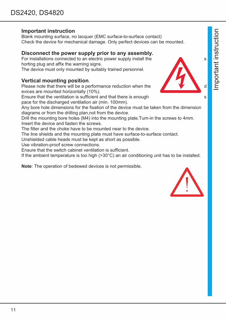
nImportant instructionBlank mounting surface, no lacquer (EMC surface-to-surface contact)Check the device for mechanical damage. Only perfect devices can be mounted.
Disconnect the power supply prior to any assembly.For installations connected to an electric power supply install the shorting plug and affix the warning signs.The device must only mounted by suitably trained personnel.
Vertical mounting position.Please note that there will be a performance reduction when the devices are mounted horizontally (10%).Ensure that the ventilation is sufficient and that there is enough space for the discharged ventilation air (min. 100mm).Any bore hole dimensions for the fixation of the device must be taken from the dimensiondiagrams or from the drilling plan,not from the device.Drill the mounting bore holes (M4) into the mounting plate.Turn-in the screws to 4mm.Insert the device and fasten the screws.The filter and the choke have to be mounted near to the device.The line shields and the mounting plate must have surface-to-surface contact.Unshielded cable heads must be kept as short as possible.Use vibration-proof screw connections.Ensure that the switch cabinet ventilation is sufficient.If the ambient temperature is too high (>30°C) an air conditioning unit has to be installed.
Note: The operation of bedewed devices is not permissible.
12
DS2420, DS4820
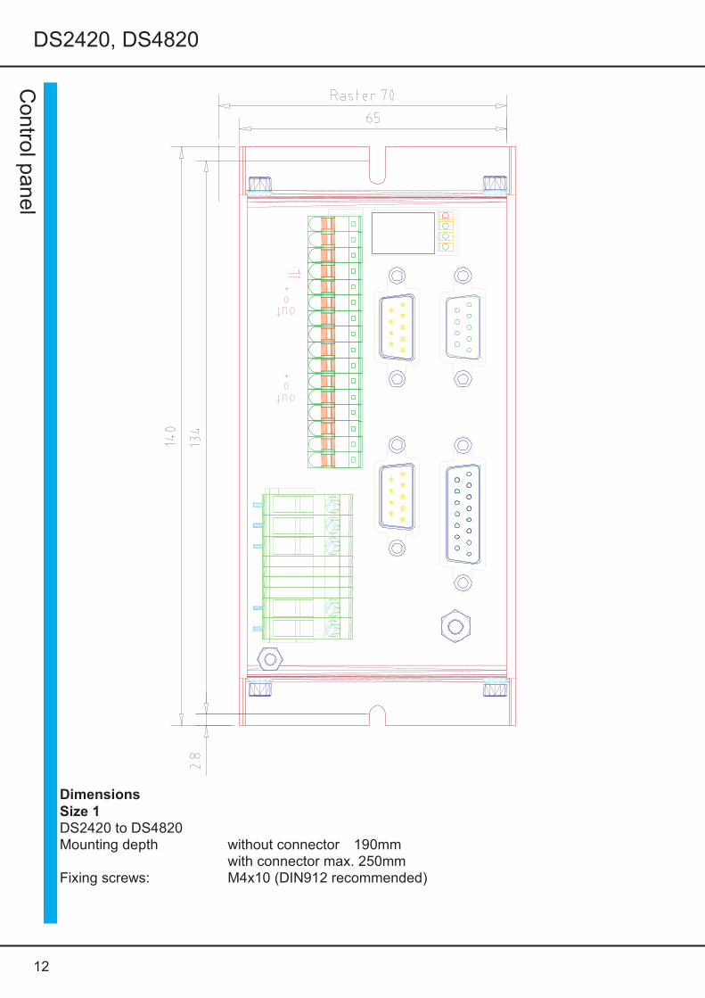
Control panel
DimensionsSize 1DS2420 to DS4820Mounting depth without connector 190mm
with connector max. 250mmFixing screws: M4x10 (DIN912 recommended)
13
DS2420, DS4820
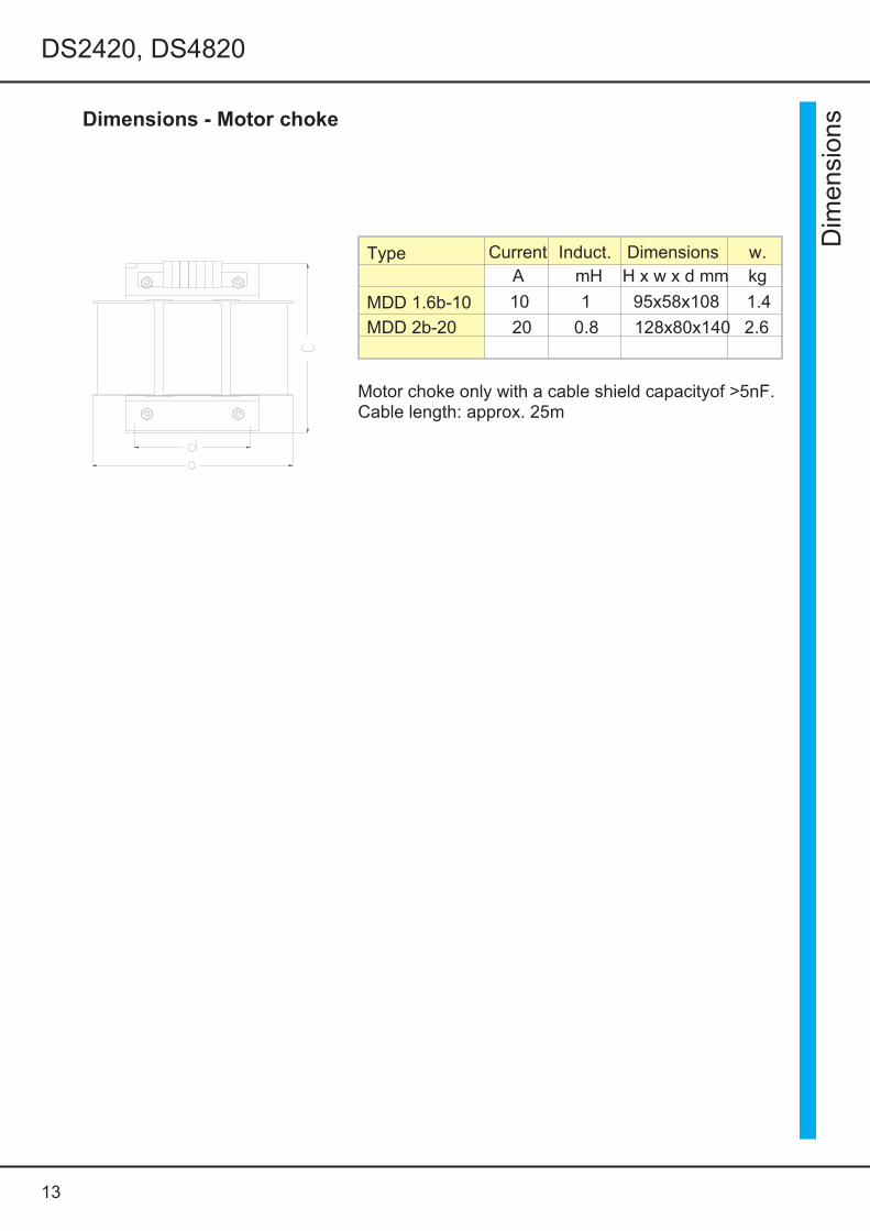
Dimensions - Motor choke
Dim
ensi
ons
Type Current Induct. Dimensions w.A mH H x w x d mm kg
MDD 1.6b-10 10 1 95x58x108 1.4
MDD 2b-20 20 0.8 128x80x140 2.6
Motor choke only with a cable shield capacityof >5nF.Cable length: approx. 25m

14
DS2420, DS4820
Mountin g
Mounting instructionRecommended fixing screwDIN912 M4x12 with safety washerBore threaded M4 holes at a right angle distanceof 312mm.Drilling template included.Turn in the M4x12 screws.Distance to the rear panel of the switch cabinetapprox. 4mmPosition the upper edge ofthe device (1) andpush it up against the stop (2). Then push thelower part of the device against the switchcabinet’s rear panel (3) and lower it (4).Fasten the screws.
Sig
nalli
neEnough space for the discharched ventilation air
Power line
Pow
er li
ne
Size 1 Size 2 Size 3
Signal line
Supply
air
Supply air Supply air Supply air
Supply
air
In order to achieve good EMC values, it is recommended to use bright, unpaintedmounting plates. The bright surface of the device’s rear panel ensure a goodsurface-to-surface contact.The signal lines and the power supply lines must be routed in separate trunkings withrectangular crossings (spatial separation of the disturbance coupling).

15
5 Elelectrical Installation
Important note:The order of the connections to the connector or terminal numbers is obligatory. All furtheradvice is non-obligatory.The input and output conductors may be altered or supplemented in accordance with theelectrical standards and guidelines.
Adhere to:- connection and operating instructions- local regulations- EU guideline 89/392/EWG- VDE and TÜV regulations and Trade body guidelines
Electrical installation should only be carried out when all voltages have beenremoved!
Ensure that the device is safely disconnected from the power supply- place the shorting plug- affix warning signs
The installation should only be carried out by suitably trained personnel for electricalengineering.- Compare the connection data with those indicated on the type plate.- Ensure that the correct fuses have been provided for the power supply and the auxiliaryvoltage.- Power supply conductors and control lines must be routed separately from
each other.Connection shields and grounding must be carried out in compliance withthe EMC guidelines. Use the correct line cross-sections.
Ele
lect
rical
inst
alla
tion

16
5 Elelectrical Installation
Circuit d iagram
Core

17
5 Elelectrical Installation
Circ
uit
diag
ram
18
5 Elelectrical Installation
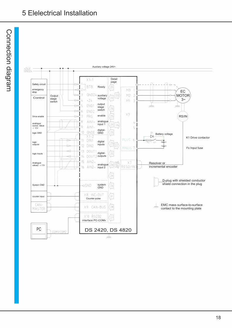
Connec tion dia gram
ControlOutputstageswitch
Ready
auxiliaryvoltage
outputstageswitch
enable
analogueinput 1
digital-GND
digitalinputs
digital-outputs
analogueinput 2
systemGND
Detailpage
Battery voltage
K1 Drive contactor
Fx Input fuse
Resolver orincremental encoder
D-plug with shielded conductorshield connection in the plug
EMC mass surface-to-surfacecontact to the mounting plate
ECMOTOR
3~
RS/IN
PC DS 2420, DS 4820

19
5 Elelectrical Installation
Con
nect
ion
diag
ram
-D
C
Ready
auxiliaryvoltage
outputstageswitch
enable
analogueinput 1
digital-GND
digitalinputs
digital-outputs
analogueinput 2
systemGND
EMC mass surface-to-surfacecontact to the mounting plate
D-plug with shielded conductorshield connection in the plug
K1 Drive contactorFx Input fuse
RS/IN
DS 2420-DC, DS 4820-DCPC
Auxiliary voltage 24V=
Control
Tacho,resolver orincremental encoder
Tacho
20
5 Elelectrical Installation
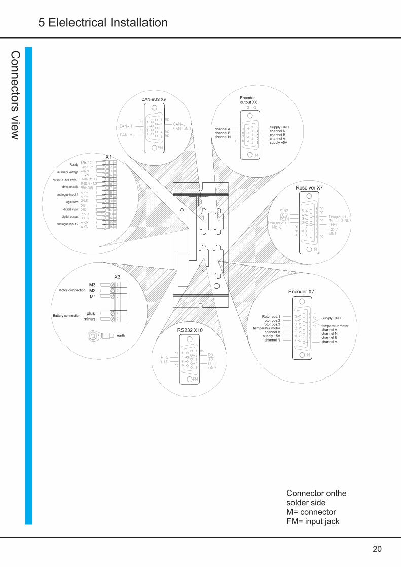
Connec tors vie w
Ready
auxiliary voltage
output stage switch
drive enable
analogue input 1
logic zero
digital input
digital output
analogue input 2
Resolver X7
Encoder X7
X3
X1
RS232 X10
Connector onthesolder sideM= connectorFM= input jack

21
5 Elelectrical Installation
Bat
tery
con
nect
ionBattery connection
WarningThe max. supply voltagemust not be exceeded atany time (not even forshort intervals)!Danger of damage!F1 = safety fuses
Feedback diode D1more safetyduring braking operation withopen contact K1 or defective fuse.
Type Batteryconnection
Connection cross - sectionmm² AWG Fuse AT Drive contactor
size
2420 positive-X3:6negative-X3:7
2.5 14 30
4810 1.5 16 204820 2.5 14 30Eart connection across the earthing point
Auxiliary voltage connectionMains potential-free auxiliary dc voltage 24V= ±10%/2AThe auxiliary voltage
- is galvanically connected with the logic voltage- is galvanically isolated from all internal supply voltages ofthe device- has internal regenerating fuses- has an EMC filter
External fuse only for line protection.
Input voltage 24V dc X1:4GND24X1:3
Residual ripple 10%Switch-on current 2ANominal current 0.8A
Mains module: negative connectionacross earth.
Po
wer
un
it
Battery voltage
Po
wer
sup
ply
24V
=
connector X4internal
Resetablefuse
DC/DCconverter
22
5 Elelectrical Installation
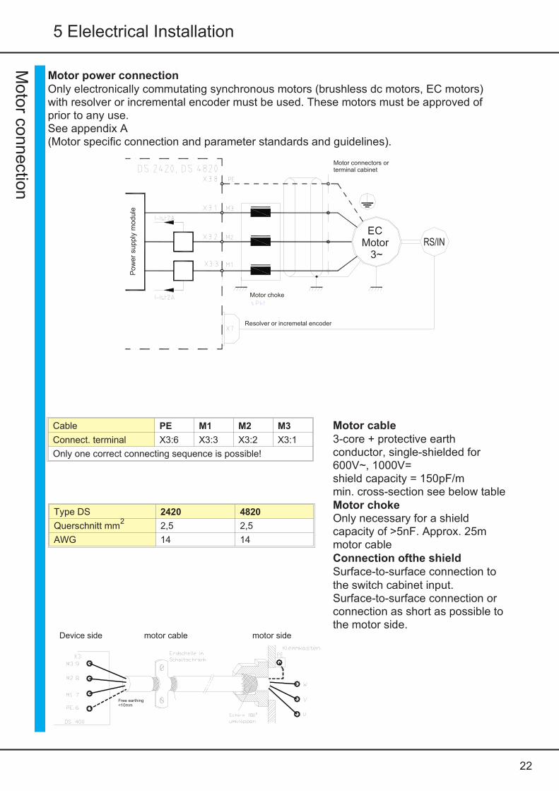
Motor power connectionOnly electronically commutating synchronous motors (brushless dc motors, EC motors)with resolver or incremental encoder must be used. These motors must be approved ofprior to any use.See appendix A(Motor specific connection and parameter standards and guidelines).
Motor c onnecti on
Motor connectors orterminal cabinet
Motor choke
Resolver or incremetal encoder
Pow
er s
uppl
y m
odul
e
ECMotor
3~RS/IN
Motor cable3-core + protective earthconductor, single-shielded for600V~, 1000V=shield capacity = 150pF/mmin. cross-section see below tableMotor chokeOnly necessary for a shieldcapacity of >5nF. Approx. 25mmotor cableConnection ofthe shieldSurface-to-surface connection tothe switch cabinet input.Surface-to-surface connection orconnection as short as possible tothe motor side.
Device side motor cable motor side
Free earthing<10mm
Cable PE M1 M2 M3
Connect. terminal X3:6 X3:3 X3:2 X3:1
Only one correct connecting sequence is possible!
Type DS 2420 4820
Querschnitt mm2
2,5 2,5
AWG 14 14

23
5 Elelectrical Installation
Mot
or c
onne
ctio
n D
C
Pow
er s
upp
ly m
odu
le
Tacho, resolver, incremental encoder TTL
Motor choke Motor connctor orterminal box
DCMOTOR
=TACHO
CASE
DS4820-DCX7
I-Ist
X3:1
X3:3
M3
M1
Motor cable
2-core + protective earth conductorsingle-shielded for 600V~,1000V=shield capacity=150pF/m
min. Cross-section 2.5mm AWG14
Motor choke
Choke with ferrous motors use forever ! Type 2El 84-25
Connection of the shield
Surface-to-surface connection to the switch cabinet input.Surface-to-surface connection or connection as short as possible to the motor side.
Motor power connection

24
5 Elelectrical Installation
Digital inputs
Digital outputs
Control signals Digital input
10 ... 30V=
DigitalinputsX1:5X1:6X1:7X1:11X1:12
Output stage switch 1Output stage switch 2EnableDigital input 1Digital input 2
DSxx/BAMO-D
Digitaloutput
24V/50mA
DigitaloutputsX1:13 digitaloutput 1 DOUT1X1:14 digitaloutput 2 DOUT2
DSxx/BAMO-D
Logicvoltage24V
Logicearth
DSxx/BAMO-D
Opto inputInput voltage
Level ON +10 to +30V
Level OFF 0 to +6V
Input current max. 14mA
Nom. voltage/nom. current +24V/10mA
Ground reference GNDE (X1:10)
Open emitter output
Output voltageLevel ON max. 24V=Level OFF <1V=Output current max. 30mAOutput resistance 220WReference voltage +24 (X1:4)Ground reference GNDE (X1:10)
Output Connections Function State Parameter
BTB/RDY X1:1, X1:2 ready fixed /relay
DOUT1 X1:13 Digital output 1 programmable DS-DRIVE-2Inputs & OutputsDOUT2 X1:14 Digital output 21 programmabler
Relay contact BTB/RDY
Contact for 48V/1AThe contact is closed when the device is ready.Indication by a green LED on the front panel.In case of an error the contact isopen.
External power supply for the inputs and outputs+24V for the logic and the auxiliary voltageGNDE logic ground
LED-BTB/RDY
BTB
DS400
BTB/RDY relay
Safetycircuit
X1:1
X1:2
Input Connection Function State1 State2 ParameterFRG/RUN X1:7 Enable fixed fixed
DS-Drive-2inputs & outputs
END1/LMT1 X1:5 Output stage switch1 fixed programableEND2/LMT2 X1:6 Output stage switch2 fixed programableDIN1 X1:11 Digital input1 programableDIN2 X1:12 Digital input2 programable

25
5 Elelectrical Installation
Con
trol
sig
nalsAnalog inputs ±10V
Features
Differential input AIN1+/AIN1- AIN2+/AIN2-
Input resistance 70k
Threshold voltage ±12V
Resolution 11Bit + sign
Parameter scale
Parameter assignment
The direction of rotation of the motor can either be changed by swapping the± connections at the differential input or by changing the signs via the parameter scale.
analoguevoltage±10V
Input Connection Basic function Voltage State Parameter
AIN1+,AIN1- X1:8, X1:9 Speed command value ±10V programmable DS-DRIVE-2Analog inputs
AIN2+,AIN2- X1:15, X1:16 Current limit ±10V programmable

26
5 Elelectrical Installation
RS 232DSxx is programmed and operated during commissioning via the serial pc interface RS232.There is a software description in the Manual DS.
Connector X10
The DSxx (D connector X10) and the serial interface (COM1/COM2) of the pc must only beconnected using a null modem cable.Do not use a null modem link cable!Install the cable only after disconnecting the device from themains.The interface is hard-coded to 115200Baud.
Interfac e
Connectoron the housing
PE on the connectorhousing
DSxx/BAMO-D
RS232
The serial interface isgalvanically connected with thedevice zero (GND).
Null modem connecting cableView to the soldered side,Shield on the housing,Max. cable length 5m
RS 232 PC
Decoupled shield
X10 DS/BAMOBIL
FM=input jack
RS 232 PC X10 DSxx/BAMO-D
PE on the connector housing
In case of strong interferences at
installed. Notebooks with a USB-RS232 converter are usually susceptible to interference.
the interface a line filter should be

27
5 Elelectrical Installation
CAN-BUSThe CAN-BUS is adigital connection totheCNC control.Optimum conditions are achieved with LABOD CNC controls.Programming and operation by means ofthe control panel viathe CAN-BUS.Interface complies with the standard ISO11898.
Adjustment and programming see Manual DS-CAN.
Inte
rfac
es
PE on the connector housing DS/BAMOBIL
PE on the connector housing
The interface is galvanicallyisolated from the device.The voltage is supplied viathe bus cable.CAN-V+ 9 to 15V=
Option:potentially isolated internalvoltage supply
FM=input jack
CAN-BUS cableUse a shielded bus conductor with a low shieldingcapacity.Signal + supply.D-connector with a metal or metallized housing.Recommended cable colours LiYCY 4x0.25+shield.
Designation Connectorno. Cable colour Cable no.
CAN-V+ 9 brown 1
CAN-GND 3 white 4
CAN-H 7 green 3
CAN-L 2 yellow 2

28
5 Elelectrical Installation
Resolve r
Motor connectorResolver
D-connector X7 DSxx/BAMO-D
Use only motors with a 2-, 4-, or 6-pole resolver whichhave been approved (AppendixA).Observe the motor specific connection data sheet!
Connector X7 15-pole D-connectorConnecting cable 4 x 2 cores, twisted in pairs and shielded, additional overall
shield.For link chains use appropriate cables!
Cable length for >25m only use high-quality resolver cables with adequateshielding properties.
Shield connection across connector X7combine all shields and connect them to the housingacross the motor the connector housing
Setting parameters see software Manual DS
Resolver connectiononly for DS 2420, DS 4820-RSConnector X7
The resolver is an absolutemeasuring system for a motorrevolution.It is robust and not impaired by highmotor temperatures.Its build corresponds to a revolvingtransformer.The rotor is supplied by thereference (10kHz).The stator supplies the sine andcosine signals modulated by therotational frequency.The amplitudes of these signals areanalyzed and digitalized in theservo-drive.The resolution is adjusted to12 bit(4096 inc/rpm).The max. possible speed is 15600.The digitalized signals are used forthe polar wheel angle, the positionand speed control, and theincremental output.The absolute accuracy is approx. ± 10arcmin.

29
5 Elelectrical Installation
Encoder connectiononly for DS2420, DS4820-IN
Incremental encoder (encoder) with2 counter tracks and 1 zero trackplus 3 rotor position tracks. Countertracks with push-pull output.Max. counting frequency 500kHz.The incremental encoder isgalvanically connected with thedevice zero (GND).Supply voltage 5V.
Steckerbelegung Lötseite
Use only motors with a Incremental (encoder) whichhave been approved (AppendixA).Observe the motor specific connection data sheet!Connector X7 15-pole D-connectorConnecting cable 10 signal conductors, shielded, min. cross-section 0.14mm
2 supply lines, min. cross-section 0.5mmFor link chains use appropriate cables!
Cable length for >25m the cross-section of the cable used must be increasedby one grade
Shield connection across connector X7- connect the shield to the connectorhousingacross the motor connector-connect the shielconnector housing
Setting parameter see software Manual DS
Enc
oder
D-connector X7 DSxx/BAMO-D
Encoder X7
encoder position 1encoder position 2encoder position 3motor temperature
channel Bsupply +5Vchannel N
channel Achannel Nchannel Bchannel A
supply GNDmotortemperature

30
5 Elelectrical Installation
SIN / COS Connectiononly for DS xx-SC
Incremental encoder with 2analog sinusoidal countertracks and1 zero track plus 2commutating tracks.Differential inputs 1Vss
Max. counting frequency500kHz
The incremental encoder isgalvanically connected withdevice zero (GND).Supply voltage 5V, providedby the servo.
The resolution is automaticallyadjusted to an optimum.
Use only motors with SIN/COS encoders (SC) which have been approved(AppendixA). Observe the motor specific connection data sheet (SC)!Connector X7 15-pole D-connectorConnecting cable 4 signal conductors,
twisted and shielded, min. cross-section 0.14mm2 signal conductors, shielded, min. cross-section 0.14mm4 supply lines, temp., min. cross-section 0.5mm
Cable type (4x(2x0.14)+(4x0.14)C+4x0.5)CFor link chains use appropriate cables!
Cable length for >25m the cross-section of the cable used must be increasedby one grade
Shield connection across connector X7-connect the shield to the connector housingacross the motor connector - connect the shield to the connectorhousing
PE on the connector housing
Motortemperature
Mo
tor
con
nec
tor
SIN
/CO
S 1
Vss
PE on the connector housing
D-connector X7DSxx/BAMO-D
TMS
factor
channel kc-channel kc+channel kd-motor temp.channel kb-supply +5Vchannel kr-
channel kd+supply GNDtemperatur GNDchannel ka-channel kr+channel kb+channel ka+
SIN/COS X7
M
nc
SIN
/CO
S 1V
ss

31
5 Elelectrical Installation
Rotor position encoderConnection via a bl-tacho
3 rotor position encoder signals(hall sensors) for thecommutation; with or without abrushless tacho.
The rotor position encoder isgalvanically connected with thedevice zero (GND).
The voltage of 15V is suppliedby the servo drive.
Provide an adapter in case thetacho voltage at rated speed issuperior to 10V~.
For lower tacho voltage connectX7 : pin 1, 9 and 11.
Connect the tacho center pointto X7:1.
Only manufacturer-approved motors with incremental encoders and rotor encoders. Note motorspecific connection sheet!Connecting plug X7 15-pole D-connectorConnecting lead 12 signal wires, shielded minimum cross section 0,25mm
Use only suitable cables in a power carrier chainCable length the next step up for a section of >25m.Shield connection a plug X7 contact shield with the plug housing
at the motor plug contact shield with the plug housing
Setting parameter see software Manual DS NDrive
Mo
tor
conn
ecto
re
nco
der
posi
tion
+ b
l tac
ho
D-connector X7Adaptor
DSxx/BAMOBIL-D
TMS
Motortemperature
PE on the connector housing PE on the connector housing
Rotor X7
rotor position 3rotor position 2rotor position 1
motor temp.tacho T
voltage supply +15Vtacho S
Supply GNDtemperature GNDtacho t+tacho S+tacho R+tacho R-
M M = pin contact
Connectorsoldered side
Enc
oder
pos
ition

32
5 Elelectrical Installation
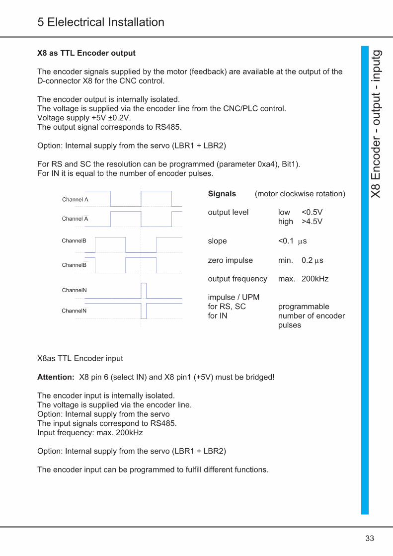
X8 TTL- Encoder output or input (2)
The D connector X8 is connected as input or output (default).Output X8 pin 6 not connected or bridge to GNDInput X8 pin 6 bridge to +5V (X8:1)
9-pin D connector (M, pins)
Connector assignment soldering side
Attention: X8 as inputX8:6 (Select IN) with X8:1 (+5V) connect withthe D connector
D-connector X8
PE on the housingDSxx/BAMOBIL-D3
soldered side
Cou
nter
CN
C/P
LCor
2.T
TL
incr
emen
tal e
nco
der
EncoderIN-OUT X8
Supply GNDchannelNchannelBchannel Asupply +5V
Channel AchannelBchannelN
select IN
X8 E
nc oder - o utput - input
33
5 Elelectrical Installation
X8 as TTL Encoder output
The encoder signals supplied by the motor (feedback) are available at the output of theD-connector X8 for the CNC control.
The encoder output is internally isolated.The voltage is supplied via the encoder line from the CNC/PLC control.Voltage supply +5V ±0.2V.The output signal corresponds to RS485.
Option: Internal supply from the servo (LBR1 + LBR2)
For RS and SC the resolution can be programmed (parameter 0xa4), Bit1).For IN it is equal to the number of encoder pulses.
X8as TTL Encoder input
Attention: X8 pin 6 (select IN) and X8 pin1 (+5V) must be bridged!
The encoder input is internally isolated.The voltage is supplied via the encoder line.Option: Internal supply from the servoThe input signals correspond to RS485.Input frequency: max. 200kHz
Option: Internal supply from the servo (LBR1 + LBR2)
The encoder input can be programmed to fulfill different functions.
Channel A
Channel A
ChannelB
ChannelB
ChannelN
ChannelN
Signals (motor clockwise rotation)
output level low <0.5Vhigh >4.5V
slope <0.1 ms
zero impulse min. 0.2 ms
output frequency max. 200kHz
impulse / UPMfor RS, SC programmablefor IN number of encoder
pulses
X8
Enc
oder
- o
utpu
t -
inpu
tg
34
5 Elelectrical Installation
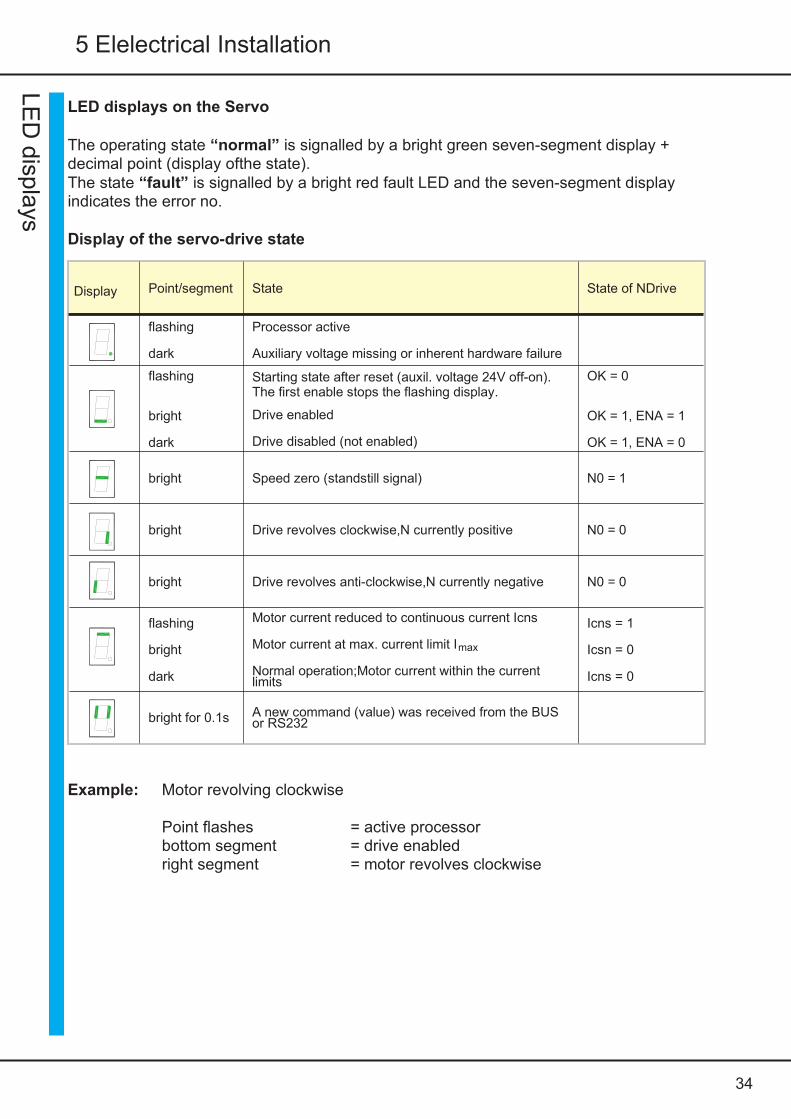
LED displays on the Servo
The operating state “normal” is signalled by a bright green seven-segment display +decimal point (display ofthe state).The state “fault” is signalled by a bright red fault LED and the seven-segment displayindicates the error no.
Display of the servo-drive state
Display Point/segment State State of NDrive
flashing
dark
Processor active
Auxiliary voltage missing or inherent hardware failure
flashing
bright
dark
Starting state after reset (auxil. voltage 24V off-on).The first enable stops the flashing display.
Drive enabled
Drive disabled (not enabled)
OK = 0
OK = 1, ENA = 1
OK = 1, ENA = 0
bright Speed zero (standstill signal) N0 = 1
bright Drive revolves clockwise,N currently positive N0 = 0
bright Drive revolves anti-clockwise,N currently negative N0 = 0
flashing
bright
dark
Motor current reduced to continuous current Icns
Motor current at max. current limit Imax
Normal operation;Motor current within the currentlimits
Icns = 1
Icsn = 0
Icns = 0
bright for 0.1s A new command (value) was received from the BUSor RS232
Example: Motor revolving clockwise
Point flashes = active processorbottom segment = drive enabledright segment = motor revolves clockwise
LED
dis plays

35
5 Elelectrical Installation
Error message on the Servo
In case of an error the red LED ‘fault’ lights up and the green 7-segment display indicatesthe error number.
Errorlist
Display on the Servo Error messageon the NDrive
Description
0 BADPARAS Parameter error
1 POWER FAULT Output stage error
2 RFE FAULT Error in the safety circuit
3 BUS TIMEOUT Transfer error BUS
4 FEEDBACK Incorrect/faulty encoder signal
5 POWERVOLTAGE No power supply voltage
6 MOTORTEMP Motor temperature too high
7 DEVICETEMP Device temperature too high
8 OVERVOLTAGE Over voltage >1.8 x UN
9 I_PEAK Overcurrent 300%
A RACEAWAY Racing (without command value, incorrectpolarity)
B USER User’s error choice
C RESERVE
D RESERVE
E CPU-ERROR Software error
F BALLAST Ballast circuitry overload
Flashing decimal point Active processor
Dark decimal point Missing auxiliary voltage or device hardware failure
Example:
FAULTLED redError no.5 Power voltage (missing power voltage)
Err
or m
essa
ge
Fa
ult

36
5 Elelectrical Installation
WarningsThe warning messages are displayed in the window ‘warnings’.
Warningmessages
Warningdisplay
WarningmessageontheNDrive Description ID-address
0x8f
0 Bit16
1 Bit17
2 Bit18
3 Bit19
4 Bit20
5 POWERVOLTAGE Undervoltage, Power voltage missing Bit21
6 MOTORTEMP Motor temperature superior to 87% Bit22
7 DEVICTEMP Device temperature superior to 87% Bit23
8 OVERVOLTAGE Overvoltage >1.5xUN Bit24
9 I_PEAK Overcurrent 200% Bit25
A Bit26
B Bit27
C I2R Overload >87% Bit28
D Bit29
E Bit30
F BALLAST Overload Regen >87% Bit31
LED displays on the servoIn case of a warning state the red LED changes (low-frequency) and the seven-segmentdisplay shows alternately the warning no. (red LED) and the operating state (LED dark).
Example:The red fault LED flashes and the display shows alternately the warning numberand the operating state.
Warning m
ess ages
Fa
ult

37
5 Elelectrical Installation
Opt
ions
5 Guarantee
38
Guarantee
Stegmaier-Haupt guarantees that the device is free from material and production defects. Testresults are recorded and archived with the serial number.The guarantee time begins from the time the device is shipped, and lasts oneyear.Stegmaier-Haupt undertakes no guarantee for devices which have been modified for special applications.During the warranty period, Stegmaier-Haupt will, at its option, either repair or replace products that prove to be defective, this includes guaranteed functional attributes. Stegmaier-Hauptspecifically disclaims the implied warranties or merchantability and fitness for a particularpurpose. For warranty service or repair, this product must be returned to a service facilitydesignated by Stegmaier-Haupt.For products returned to Stegmaier-Haupt for warranty service, the Buyer shall prepay shippingcharges to Stegmaier-Haupt shall pay shipping charges to return the product to theBuyer.However, the Buyer shall pay allshipping charges, duties, and taxes forproducts returnedto Stegmaier-Haupt from an other country.The foregoing warranty shall not apply to defects resulting from:
* improper or inadequate repairs effected by the Buyer or a third party,* non-observance of the manual which is included in all consignments,* non-observance of the electrical standards and regulations* improper maintenance* acts of nature
All further claims on transformation, diminution, and replacement of any kind of damage,especially damage, which does not affect the Stegmaier-Haupt device, can not be considered.Follow-on damage within the machine or system, which may arise due to malfunction ordefect in the device cannot be claimed.This limitation does not affect the product liability laws as applied in the place ofmanufacture (i. e. Germany).
Stegmaier-Haupt reserves the right to change any information included in this MANUAL.All connection circuitry described is meant for general information purposes and is notmandatory.The local legal regulations, and those of the Standards Authorities have to be adhered to.Stegmaier-Haupt does not assume any liability, expressively or inherently, for the informationcontained in this MANUAL, for the functioning of the device or its suitability for any specificapplication.
All rights are reserved.Copying, modifying and translations lie outside Stegmaier-Haupt’s liability and thus are notprohibited. Stegmaier-Haupt’s products are not authorised for use as critical components inthe life support devices or systems without express written approval.The onus is on the reader to verify that the information here is current.
Guaran tee
Stegmaier-Haupt GmbH * Tel.: 06222-61021 * Fax: 06222 64988 * Email: [email protected]