00 couv en - · afnor/ute..... 65 balancing ... a8 - 900 range, 0 to 900 min-1 20-21 a9 - 750...
TRANSCRIPT

4122 en - 2008.11 / e
LSRLSRPMSynchronous motors with permanent magnetsSynchronous motors with permanent magnets
Aluminium alloy housing, 0.75 to 400 kWTechnical catalogueTechnical catalogue


Permanent magnet synchronous motorsLSRPM
1
ContentsPAGE
GENERAL - EFFICIENCIES...................................... 3
SELECTION METHOD .............................................. 4
- PERFORMANCE ............................................... 5
- EQUIPMENT AND OPTIONS .......................... 25
- ELECTRICAL CHARACTERISTICS ............... 33
PAGE
- DIMENSIONS ...................................................45
- CONSTRUCTION .............................................53
- GENERAL INFORMATION ..............................63
A1 - 5500 range, 0 to 5500 min-1 7
A2 - 4500 range, 0 to 4500 min-1 8-9
A3 - 3600 range, 0 to 3600 min-1 10-11
A4 - 3000 range, 0 to 3000 min-1 12-13
A5 - 2400 range, 0 to 2400 min-1 14-15
A6 - 1800 range, 0 to 1800 min-1 16-17
A7 - 1500 range, 0 to 1500 min-1 18-19
A8 - 900 range, 0 to 900 min-1 20-21
A9 - 750 range, 0 to 750 min-1 22-23
A10 - 375 range, 0 to 375 min-1 24
B1 - Position sensor 26 to 27
B2 - Forced ventilation 28
B3 - Reinforced insulation 29
B4 - Cable glands 30
B5 - Thermal protection 31
C1 - Characteristic data 34 to 43
D1 - Shaft extensions 46
D2 - Foot mounted IM B3 (IM 1001) 47
D3 - Foot and flange mounted IM B35 (IM 2001) 48
D4 - Flange mounted IM B5 (IM 3001) 49
D5 - Foot and face mounted IM B34 (IM 2101) 50
D6 - Face mounted IM B14 (IM 3601) 51
D7 - Motor with options 52
E1 - Definition of "Index of Protection" (IP/IK) 54
E2 - Components 55
E3 - External finish 56
E4 - Mounting arrangements 57
E5 - Bearings and lubrication 58
E6 - Connection 59
E7 - Machine vibration levels 60 to 61
F1 - Quality commitment 64
F2 - Standards and approvals 65 to 67
F3 - Designation 68

Permanent magnet synchronous motorsLSRPM
2
IndexPAGE
Absolute encoder .............................................................. 27AFNOR/UTE...................................................................... 65
Balancing........................................................................... 60Bearings ....................................................................... 55-58
Cable gland .................................................................. 30-59Connection diagrams.................................................... 28-59Connection .................................................................. 28-59Connection ................................................................... 27-59Construction ...................................................................... 55
Description......................................................................... 55Designation........................................................................ 68Dimensions of the LSRPM with its options........................ 52Dimensions of the LSRPM ....................................... 45 to 51DIN/VDE............................................................................ 65
Electrical characteristics ............................................... 33-43End shields........................................................................ 55External finish .................................................................... 56
Fan cover........................................................................... 55Forced ventilation .............................................................. 28
Grease............................................................................... 58
Housing with cooling fins ................................................... 55
Identification ...................................................................... 68IEC..................................................................................... 65Incremental encoder.......................................................... 27ISO 9001 ........................................................................... 64
JIS ..................................................................................... 65
Labyrinth seal .................................................................... 55Lipseals ............................................................................. 55Lubrication of bearings ...................................................... 58
PAGE
Mechanical speeds............................................................ 61Motor efficiencies..................................................... 3-7 to 24Motor torques ................................................................. 4-24Mounting arrangements..................................................... 57Mountings .......................................................................... 57
NEMA ................................................................................ 65
Operating positions............................................................ 57Options ................................................................ 25 to 31-52
Paint systems .................................................................... 56Performance on drives ............................................... 4 to 24Protection indices .............................................................. 54
Quality ............................................................................... 64
Reinforced insulation ......................................................... 29Rotor.................................................................................. 55
Selection......................................................................... 4-24Sensor .......................................................................... 26-27Shaft .................................................................................. 55STANDARDS ........................................................... 65 to 67Stator ................................................................................. 55
Terminal block with terminals ............................................ 59Terminal box ................................................................ 55-59Thermal protection............................................................. 31Torque and efficiency characteristics ......................... 4 to 24
UL/CSA.............................................................................. 64
Vibration levels .................................................................. 60Vibration ................................................................... 60 to 61

LSRPMPermanent magnet synchronous motors
General - Efficiencies
3
LEROY-SOMER permanent magnet synchronous motors in the LSRPM range have efficiencies that are higher than those of induction motors andmore stable over the entire selected speed range (see graph below).
Efficiencies of synchronous motors and induction motors as a function of speed
Efficiencies of synchronous motors and induction motors supplied by inverters:
Efficiency of permanent magnet synchronous motors
Apart from a few exceptions, synchronous motors cannot operate correctly on a traditional sinusoidal mains supply. They are practically alwayssupplied via a variable speed drive (VSD). This catalogue gives the efficiencies of LSRPM motors supplied via LEROY-SOMER VSDs’.
Efficiency of induction motors supplied via drives:
As a general rule, the efficiencies of induction motors given in the catalogues are values measured on a sinusoidal mains supply at the rated powerand speed.
The voltage and current waveforms created by the drive are not sinusoidal. Supplying via a drive therefore results in additional losses in the motor.According to specifications 60034-17, these are estimated at 20% of the total losses. These losses have a direct impact on the declared efficiencyof the motor.
In variable speed mode, this efficiency should therefore be corrected in accordance with the formula below.
2 = 1- (1 - 1 ) x 1.2
2 = efficiency of induction motor obtained on a drive
1 = efficiency of induction motor supplied from the mains
Example: 200 kW application at 3000 min-1
1: Efficiency of the 200 kW, 2-pole induction motor on 50 Hz mains supply = 96%
2: Estimated efficiency of the same induction motor supplied via a drive at 50 Hz
2 = 1 – (1- 0.96) x 1.2 = 0.952 i.e. 95.2%
For the same rated power and supply conditions, the efficiency of the LSRPM motor = 97.5%
40
50
60
70
80
90
100
100 1000 10000
Speed (rpm)
Effic
ienc
y (%
)
LSRPM synchronousmotor
Induction motor

4
LSRPMPermanent magnet synchronous motors
Selection method
EXAMPLEA machine requires a torque of 1050 N.m over a speed range of 300 to 2300 min-1 in continuous duty.
Choice of motor1) Selecting the range according to the speed range
2) Selecting the torque range
3) Selecting the motor: choose the curve that has a torque immediately higher than the application requirements.
4) Reading the efficiency: the graph shows the curves of efficiency as a function of speed
5) Other characteristics:– Electrical, pages 34 to 43– Dimensional, pages 46 to 52
LEROY-SOMER reserves the right to modify the design, technical specifications and dimensions of the products shown in this document. The descriptions cannot in any way be considered contractual.
91
96
97
0 500 1000 1500 2000 2500
1
32
Example : Curve no. 2 Efficiency of the selected motor at
1500 min-1 = 97%
A5.5 - Couple de 755 à 1235 N.m
A5 - Gamme 2400 de 0 à 2400 min
700
900
1100
1200
0 500 1000 1500 2000 2500
1 LSRPM 315 SR : 2400 min-1 / 310 kW / 607 A
2 LSRPM 315 SP : 2400 min-1 / 285 kW / 567 A
Example : Selection of the torque range 755 to 1235 N.m
for a torque requirement of 1050 N.m
Moteurs synchrones à aimants permanentsLSRPM
Performances
Couple de 0 à 1080 N.m
Couple de 0 à 1235 N.m
A4 - Gamme 3000 de 0 à 3000 min-1 12-13
A5 - Gamme 2400 de 0 à 2400 min-1 14-15
A6 - Gamme 1800 de 0 à 1800 min-1 16-17
Example: Selection of the 2400 range for operation over a speed range of 300 to 2300 min-1
700
1100
1200
0 500 1000 1500 2000 2500
1 LSRPM 315 SR : 2400 min-1 / 310 kW / 607 A
2 LSRPM 315 SP : 2400 min-1 / 285 kW / 567 A
Example : Selection of curve 2 for an application requirement of 1050 N.m
Typemoteur
2 LSRPM 315 SP : 2400 min-1 / 285 kW / 567 A
Vitessenominale
Puissancenominale
Intensiténominale

LSRPMPermanent magnet synchronous motors
Performance
5
PAGE
Torque from 0 to 240 N.m
Torque from 0 to 490 N.m
Torque from 0 to 1035 N.m
Torque from 0 to 1080 N.m
Torque from 0 to 1235 N.m
Torque from 0 to 1220 N.m
Torque from 0 to 1400 N.m
Torque from 0 to 1380 N.m
Torque from 0 to 1400 N.m
Torque from 0 to 130 N.m
The performances given are those of LSRPM motors used in conjunction with LEROY-SOMER drives.The values and tolerances conform to IEC 60034-1.
A1 - 5500 range, 0 to 5500 min-1 7
A2 - 4500 range, 0 to 4500 min-1 8-9
A3 - 3600 range, 0 to 3600 min-1 10-11
A4 - 3000 range, 0 to 3000 min-1 12-13
A5 - 2400 range, 0 to 2400 min-1 14-15
A6 - 1800 range, 0 to 1800 min-1 16-17
A7 - 1500 range, 0 to 1500 min-1 18-19
A8 - 900 range, 0 to 900 min-1 20-21
A9 - 750 range, 0 to 750 min-1 22-23
A10 - 375 range, 0 to 375 min-1 24


LSRPMPermanent magnet synchronous motors
Performance
7
A1.1 - Torque from 0 to 24 N.m
A1.2 - Torque from 24 to 90 N.m
A1.3 - Torque from 90 to 240 N.m
For operation at very low speeds, see the equipment and options section, pages 26, 27 and 28.
0 1000 2000 3000 4000 5000 600020
30
40
50
60
70
80
90
0 1000 2000 3000 4000 5000 600087
89
91
93
95
88
90
92
94
96
10 LSRPM 132 M : 5500 min-1 / 18,6 kW / 35 A
9 LSRPM 132 M : 5500 min-1 / 23 kW / 44 A
8 LSRPM 132 M : 5500 min-1 / 27 kW / 52 A
7 LSRPM 160 MP : 5500 min-1 / 35 kW / 67 A
6 LSRPM 160 MP : 5500 min-1 / 44 kW / 82 A
5 LSRPM 160 LR : 5500 min-1 / 52 kW / 97 A
7 8
9
65
10
A1 - 5500 range, 0 to 5500 min-1
0 1000 2000 3000 4000 5000 6000 0 1000 2000 3000 4000 5000 6000
10
15
20
25
85
86
87
88
89
90
91
92
93
94
15
13 1411 12
15 LSRPM 90 SL : 5500 min-1 / 6.9 kW / 12.7 A
14 LSRPM 90 L : 5500 min-1 / 8.6 kW / 15.8 A
13 LSRPM 100 L : 5500 min-1 / 10.4 kW / 19 A
12 LSRPM 100 L : 5500 min-1 / 12.1 kW / 22 A
11 LSRPM 100 L : 5500 min-1 / 13.8 kW / 25 A
0 1000 2000 3000 4000 5000 6000 0 1000 2000 3000 4000 5000 600050
100
150
200
250
88
89
90
91
92
93
94
95
96
32
1
41 LSRPM 200 L1 : 5500 min-1 / 140 kW / 267 A
2 LSRPM 200 L : 5500 min-1 / 100 kW / 195 A
3 LSRPM 200 L : 5500 min-1 / 85 kW / 169 A
4 LSRPM 200 L : 5500 min-1 / 70 kW / 138 A

8
LSRPMPermanent magnet synchronous motors
Performance
A2.1 - Torque from 0 to 29 N.m
A2.2 - Torque from 29 to 110 N.m
A2.3 - Torque from 110 to 360 N.m
For operation at very low speeds, see the equipment and options section, pages 26, 27 and 28.
A2 - 4500 range, 0 to 4500 min-1
0 1000 2000 3000 4000 5000 0 1000 2000 3000 4000 5000
10
15
20
30
25
85
86
87
88
89
90
91
92
93
9418
16 17
14 15
18 LSRPM 90 SL : 4500 min-1 / 6.8 kW / 12.6 A
17 LSRPM 90 L : 4500 min-1 / 8.5 kW / 15.7 A
16 LSRPM 100 L : 4500 min-1 / 10.2 kW / 18.8 A
15 LSRPM 100 L : 4500 min-1 / 12 kW / 22 A
14 LSRPM 100 L : 4500 min-1 / 13.7 kW / 25 A
0 1000 2000 3000 4000 5000 0 1000 2000 3000 4000 5000
20
40
60
80
100
87
89
91
93
95
88
90
92
94
96
1112 13
9810
13 LSRPM 132 M : 4500 min-1 / 18,6 kW / 35 A
12 LSRPM 132 M : 4500 min-1 / 23 kW / 45 A
11 LSRPM 132 M : 4500 min-1 / 27 kW / 51 A
10 LSRPM 160 MP : 4500 min-1 / 35 kW / 67 A
9 LSRPM 160 MP : 4500 min-1 / 44 kW / 81 A
8 LSRPM 160 LR : 4500 min-1 / 52 kW / 97 A
0 2000 3000 40001000 5000 0 2000 3000 40001000 5000100
150
200
250
300
350
88
89
90
91
92
93
94
95
96
97 32
54
6
7
2 LSRPM 225 SR1 : 4500 min-1 / 170 kW / 313 A
3 LSRPM 200 LU1 : 4500 min-1 / 150 kW / 288 A
4 LSRPM 200 L1 : 4500 min-1 / 120 kW / 230 A
5 LSRPM 200 L : 4500 min-1 / 100 kW / 186 A
6 LSRPM 200 L : 4500 min-1 / 80 kW / 157 A
7 LSRPM 200 L : 4500 min-1 / 65 kW / 128 A

LSRPMPermanent magnet synchronous motors
Performance
9
A2 - 4500 range, 0 to 4500 min-1
A2.4 - Torque from 360 to 490 N.m
For operation at very low speeds, see the equipment and options section, pages 26, 27 and 28.
0 2000 3000 40001000 5000 0 2000 3000 40001000 5000400
500
450
550
93
94
95
96
971
1 LSRPM 250 SE : 4500 min-1 / 230 kW / 415 A

10
LSRPMPermanent magnet synchronous motors
Performance
A3 - 3600 range, 0 to 3600 min-1
A3.1 - Torque from 0 to 34 N.m
A3.2 - Torque from 34 to 130 N.m
A3.3 - Torque from 130 to 330 N.m
For operation at very low speeds, see the equipment and options section, pages 26, 27 and 28.
0 300020001000 4000
10
15
20
25
30
35
80
82
84
86
88
90
92
94
0 300020001000 4000
2220 2118 19
22 LSRPM 90 SL : 3600 min-1 / 6.4 kW / 11.9 A
21 LSRPM 90 L : 3600 min-1 / 8 kW / 14,8 A
20 LSRPM 100 L : 3600 min-1 / 9.6 kW / 17.6 A
19 LSRPM 100 L : 3600 min-1 / 11.2 kW / 21 A
18 LSRPM 100 L : 3600 min-1 / 12.8 kW / 23 A
20
40
60
80
100
120
87
89
91
93
95
88
90
92
94
96
0 300020001000 40000 300020001000 4000
1516 1714
1312
17 LSRPM 132 M : 3600 min-1 / 17,6 kW / 33 A
16 LSRPM 132 M : 3600 min-1 / 22 kW / 41 A
15 LSRPM 132 M : 3600 min-1 / 26 kW / 48 A
14 LSRPM 160 MP : 3600 min-1 / 34 kW / 63 A
13 LSRPM 160 MP : 3600 min-1 / 41 kW / 77 A
12 LSRPM 160 LR : 3600 min-1 / 49 kW / 91 A
0 1000 2000 3000 4000 0 1000 2000 3000 4000100
150
200
250
300
89
91
93
95
88
90
92
94
96
977
910
11
8
7 LSRPM 200 LU1 : 3600 min-1 / 125 kW / 241 A
8 LSRPM 200 L1 : 3600 min-1 / 105 kW / 201 A
9 LSRPM 200 L : 3600 min-1 / 85 kW / 163 A
10 LSRPM 200 L : 3600 min-1 / 70 kW / 140 A
11 LSRPM 200 L : 3600 min-1 / 50 kW / 105 A

LSRPMPermanent magnet synchronous motors
Performance
11
A3 - 3600 range, 0 to 3600 min-1
A3.4 - Torque from 330 to 770 N.m
A3.5 - Torque from 770 to 1035 N.m
For operation at very low speeds, see the equipment and options section, pages 26, 27 and 28.
0 1000 2000 3000 4000 0 1000 2000 3000 4000350
450
550
650
750
91
92
93
94
95
96
973 5
6
4
6 LSRPM 250 SE : 3600 min-1 / 165 kW / 311 A
5 LSRPM 250 SE : 3600 min-1 / 190 kW / 363 A
4 LSRPM 280 SC : 3600 min-1 / 240 kW / 450 A
3 LSRPM 280 SD : 3600 min-1 / 290 kW / 540 A
0 1000 2000 3000 4000 0 1000 2000 3000 400091
92
93
94
95
96
97
800
850
900
950
1000
1050
1
2
1 LSRPM 315 SP : 3600 min-1 / 390 kW / 765 A
2 LSRPM 280 MK : 3600 min-1 / 325 kW / 653 A

12
LSRPMPermanent magnet synchronous motors
Performance
A4.1 - Torque from 0 to 37 N.m
A4.2 - Torque from 37 to 140 N.m
A4.3 - Torque from 140 to 365 N.m
For operation at very low speeds, see the equipment and options section, pages 26, 27 and 28.
A4 - 3000 range, 0 to 3000 min-1
0 1000 2000 3000 0 1000 2000 300010
15
20
25
30
35
75
77
79
81
83
85
87
89
91
93
22
20 2118 19
22 LSRPM 90 SL : 3000 min-1 / 5.8 kW / 11 A
21 LSRPM 90 L : 3000 min-1 / 7.3 kW / 13.5 A
20 LSRPM 100 L : 3000 min-1 / 8.7 kW / 16.2 A
19 LSRPM 100 L : 3000 min-1 / 10.2 kW / 18.8 A
18 LSRPM 100 L : 3000 min-1 / 11.6 kW / 21 A
8120
40
60
80
100
120
140
89
93
87
91
83
85
95
0 1000 2000 30000 1000 2000 3000
15 1617
141312
17 LSRPM 132 M : 3000 min-1 / 15,8 kW / 30 A
16 LSRPM 132 M : 3000 min-1 / 19,7 kW / 38 A
15 LSRPM 132 M : 3000 min-1 / 23 kW / 44 A
14 LSRPM 160 MP : 3000 min-1 / 30 kW / 57 A
13 LSRPM 160 MP : 3000 min-1 / 37 kW / 69 A
12 LSRPM 160 LR : 3000 min-1 / 44 kW / 82 A
88
89
90
91
92
93
94
95
96
97
0 1000 2000 30000 1000 2000 3000100
200
300
10
11
7 89
7 LSRPM 225 ST1 : 3000 min-1 / 115 kW / 230 A
8 LSRPM 200 L1 : 3000 min-1 / 105 kW / 209 A
9 LSRPM 200 L : 3000 min-1 / 85 kW / 166 A
10 LSRPM 200 L : 3000 min-1 / 65 kW / 129 A
11 LSRPM 200 L : 3000 min-1 / 50 kW / 102 A

LSRPMPermanent magnet synchronous motors
Performance
13
A4 - 3000 range, 0 to 3000 min-1
A4.4 - Torque from 365 to 700 N.m
A4.5 - Torque from 700 to 1080 N.m
For operation at very low speeds, see the equipment and options section, pages 26, 27 and 28.
400
500
600
700
88
89
90
91
92
93
94
95
96
97
0 1000 2000 30000 1000 2000 3000
4 564 LSRPM 280 SC : 3000 min-1 / 220 kW / 428 A
5 LSRPM 250ME : 3000 min-1 / 170 kW / 338 A
6 LSRPM 250SE : 3000 min-1 / 145 kW / 279 A
700
800
900
1000
1100
88
89
90
91
92
93
94
95
96
97
0 1000 2000 30000 1000 2000 3000
312
1 LSRPM 315 SP : 3000 min-1 / 340 kW / 656 A
2 LSRPM 280 MK : 3000 min-1 / 290 kW / 579 A
3 LSRPM 280 MD : 3000 min-1 / 260 kW / 495 A

14
LSRPMPermanent magnet synchronous motors
Performance
A5.1 - Torque from 0 to 38 N.m
A5.2 - Torque from 38 to 145 N.m
A5.3 - Torque from 145 to 400 N.m
For operation at very low speeds, see the equipment and options section, pages 26, 27 and 28.
A5 - 2400 range, 0 to 2400 min-1
0 500 1000 1500 2000 25000 500 1000 1500 2000 2500
10
15
20
25
30
35
75
77
85
79
87
81
89
83
91
93
22
18 19
20 21
22 LSRPM 90 SL : 2400 min-1 / 4.8 kW / 9.1 A
21 LSRPM 90 L : 2400 min-1 / 6 kW / 11.2 A
20 LSRPM 100 L : 2400 min-1 / 7.2 kW / 13.4 A
19 LSRPM 100 L : 2400 min-1 / 8.4 kW / 15.6 A
18 LSRPM 100 L : 2400 min-1 / 9.5 kW / 17.7 A
20
40
60
80
100
120
140
80
82
84
86
88
90
92
94
0 500 1000 1500 2000 25000 500 1000 1500 2000 2500
15
16 17
141312
17 LSRPM 132 M : 2400 min-1 / 13.1 kW / 25 A
16 LSRPM 132 M : 2400 min-1 / 16.3 kW / 31 A
15 LSRPM 132 M : 2400 min-1 / 19.2 kW / 37 A
14 LSRPM 160 MP : 2400 min-1 / 25 kW / 47 A
13 LSRPM 160 MP : 2400 min-1 / 31 kW / 58 A
12 LSRPM 160 LR : 2400 min-1 / 36 kW / 69 A
89
90
91
92
93
94
95
96
97
0 500 1000 1500 2000 25000 500 1000 1500 2000 2500100
200
300
400 7 LSRPM 225 MR : 2400 min-1 / 100 kW / 193 A
8 LSRPM 200 L : 2400 min-1 / 80 kW / 168 A
9 LSRPM 200 L : 2400 min-1 / 65 kW / 137 A
10 LSRPM 200 L : 2400 min-1 / 50 kW / 101 A
11 LSRPM 200 L : 2400 min-1 / 37.5 kW / 75 A
78910
11

LSRPMPermanent magnet synchronous motors
Performance
15
A5.4 - Torque from 400 to 755 N.m
A5.5 - Torque from 755 to 1235 N.m
For operation at very low speeds, see the equipment and options section, pages 26, 27 and 28.
A5 - 2400 range, 0 to 2400 min-1
89
90
91
92
93
94
95
96
97
400
500
600
700
0 500 1000 1500 2000 25000 500 1000 1500 2000 2500
4 LSRPM 280 SD : 2400 min-1 / 190 kW / 353 A
5 LSRPM 250 ME : 2400 min-1 / 150 kW / 300 A
6 LSRPM 250 SE : 2400 min-1 / 125kW / 243 A
4 56
91
92
93
94
95
96
97
700
800
900
1000
1100
1200
0 500 1000 1500 2000 25000 500 1000 1500 2000 2500
1
32
1 LSRPM 315 SR : 2400 min-1 / 310 kW / 607 A
2 LSRPM 315 SP : 2400 min-1 / 285 kW / 567 A
3 LSRPM 280 MK : 2400 min-1 / 230 kW / 462 A

16
LSRPMPermanent magnet synchronous motors
Performance
A6 - 1800 range, 0 to 1800 min-1
A6.1 - Torque from 0 to 38 N.m
A6.2 - Torque from 38 to 145 N.m
A6.3 - Torque from 145 to 370 N.m
For operation at very low speeds, see the equipment and options section, pages 26, 27 and 28.
0 500 1000 1500 2000 0 500 1000 1500 2000
10
15
20
25
30
35
75
77
79
81
83
85
87
89
91
22
18 19
20 21
22 LSRPM 90 SL : 1800 min-1 / 3.6 kW / 6.9 A
21 LSRPM 90 L : 1800 min-1 / 4.5 kW / 8.5 A
20 LSRPM 100 L : 1800 min-1 / 5.4 kW / 10.2 A
19 LSRPM 100 L : 1800 min-1 / 6.3 kW / 11.8 A
18 LSRPM 100 L : 1800 min-1 / 7.2 kW / 13.4 A
0 500 1000 1500 2000 0 500 1000 1500 2000
20
40
60
80
100
120
140
81
83
85
87
89
91
93 151617
141312
17 LSRPM 132 M : 1800 min-1 / 9.8 kW / 19 A
16 LSRPM 132 M : 1800 min-1 / 12.3 kW / 24 A
15 LSRPM 132 M : 1800 min-1 / 14.4 kW / 28 A
14 LSRPM 160 MP : 1800 min-1 / 18.7 kW / 36 A
13 LSRPM 160 MP : 1800 min-1 / 23 kW / 44 A
12 LSRPM 160 LR : 1800 min-1 / 27.3 kW / 52 A
86
88
90
92
94
96
100
200
300
0 500 1000 1500 2000 0 500 1000 1500 2000
8 LSRPM 225 ST : 1800 min-1 / 70 kW / 142 A
9 LSRPM 200 L : 1800 min-1 / 55 kW / 111.5 A
10 LSRPM 200 L : 1800 min-1 / 40 kW / 82.5 A
11 LSRPM 200 L : 1800 min-1 / 33 kW / 70.5 A
8
9 10
11

LSRPMPermanent magnet synchronous motors
Performance
17
A6 - 1800 range, 0 to 1800 min-1
A6.4 - Torque from 370 to 800 N.m
A6.5 - Torque from 800 to 1220 N.m
For operation at very low speeds, see the equipment and options section, pages 26, 27 and 28.
88
90
92
94
96
400
500
600
700
800
0 500 1000 1500 2000 0 500 1000 1500 2000
4 LSRPM 280 SD : 1800 min-1 / 150 kW / 295 A
5 LSRPM 280 SC : 1800 min-1 / 125 kW / 248 A
6 LSRPM 250 ME : 1800 min-1 / 100 kW / 204 A
7 LSRPM 225 MR : 1800 min-1 / 85 kW / 172 A
4 567
93
91
95
97
92
94
96
700
800
900
1000
1100
1200
0 500 1000 1500 2000 0 500 1000 1500 2000
1 LSRPM 315 SR : 1800 min-1 / 230 kW / 457 A
2 LSRPM 315 SP : 1800 min-1 / 195 kW / 387 A
3 LSRPM 280 MK : 1800 min-1 / 175 kW / 363 A
123

18
LSRPMPermanent magnet synchronous motors
Performance
A7 - 1500 range, 0 to 1500 min-1
A7.1 - Torque from 0 to 38 N.m
A7.2 - Torque from 38 to 145 N.m
A7.3 - Torque from 145 to 350 N.m
For operation at very low speeds, see the equipment and options section, pages 26, 27 and 28.
10
15
20
25
30
35
75
77
79
81
83
85
87
89
91
0 500 1000 1500 0 500 1000 1500
22
18 19
20
21
22 LSRPM 90 SL : 1500 min-1 / 3 kW / 5.9 A
21 LSRPM 90 L : 1500 min-1 / 3.7 kW / 7.2 A
20 LSRPM 100 L : 1500 min-1 / 4.5 kW / 8.6 A
19 LSRPM 100 L : 1500 min-1 / 5.2 kW / 9.9 A
18 LSRPM 100 L : 1500 min-1 / 6 kW / 11.2 A
20
40
60
80
100
120
140
77
79
81
83
85
87
89
91
93
0 500 1000 1500 0 500 1000 1500
15 1617
141312
17 LSRPM 132 M : 1500 min-1 / 8.2 kW / 16 A
16 LSRPM 132 M : 1500 min-1 / 10.2 kW / 19.9 A
15 LSRPM 132 M : 1500 min-1 / 12 kW / 23 A
14 LSRPM 160 MP : 1500 min-1 / 15.6 kW / 30 A
13 LSRPM 160 MP : 1500 min-1 / 19.2 kW / 30 A
12 LSRPM 160 LR : 1500 min-1 / 22.8 kW / 43 A
88
89
90
91
92
93
94
95
96
97
100
200
300
0 500 1000 1500 0 500 1000 1500
8 LSRPM 200 LU : 1500 min-1 / 55 kW / 105 A
9 LSRPM 200 L : 1500 min-1 / 40 kW / 78.5 A
10 LSRPM 200 L : 1500 min-1 / 33 kW / 67 A
11 LSRPM 200 L : 1500 min-1 / 25 kW / 51.5 A
89
10
11
LSRPMPermanent magnet synchronous motors
Performance
19
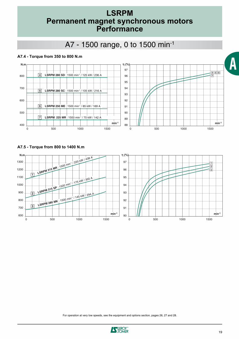
A7 - 1500 range, 0 to 1500 min-1
A7.4 - Torque from 350 to 800 N.m
A7.5 - Torque from 800 to 1400 N.m
For operation at very low speeds, see the equipment and options section, pages 26, 27 and 28.
88
89
90
91
92
93
94
95
96
97
400
500
600
700
800
0 500 1000 1500 0 500 1000 1500
4 LSRPM 280 SD : 1500 min-1 / 125 kW / 236 A
5 LSRPM 280 SC : 1500 min-1 / 105 kW / 216 A
6 LSRPM 250 ME : 1500 min-1 / 85 kW / 169 A
7 LSRPM 225 MR : 1500 min-1 / 70 kW / 142 A
4 5 67
600
700
800
900
1000
1100
1200
1300
90
91
92
93
94
95
96
97
0 500 1000 15000 500 1000 1500
1 LSRPM 315 MR : 1500 min-1 / 220 kW / 438 A
2 LSRPM 315 SP : 1500 min-1 / 175 kW / 355 A
3 LSRPM 280 MK : 1500 min-1 / 145 kW / 294 A
1
3
2

20
LSRPMPermanent magnet synchronous motors
Performance
A8.1 - Torque from 0 to 38 N.m
A8.2 - Torque from 38 to 145 N.m
A8.3 - Torque from 145 to 350 N.m
For operation at very low speeds, see the equipment and options section, pages 26, 27 and 28.
100
200
300
80
82
84
86
88
90
92
0 800600400200 1000 0 800600400200 1000
8 LSRPM 200 LU : 900 min-1 / 33 kW / 65 A
9 LSRPM 200 L : 900 min-1 / 25 kW / 50,2 A
10 LSRPM 200 L : 900 min-1 / 20 kW / 42,5 A
11 LSRPM 200 L : 900 min-1 / 15 kW / 33,5 A
8910
11
A8 - 900 range, 0 to 900 min-1
0 800600400200 1000 0 800600400200 1000
10
15
20
25
30
35
60
65
70
75
80
85
22
181920
21
22 LSRPM 90 SL : 900 min-1 / 1.8 kW / 3.8 A 21 LSRPM 90 L : 900 min-1 / 2.2 kW / 4.6 A
20 LSRPM 100 L : 900 min-1 / 2.7 kW / 5.4 A 19 LSRPM 100 L : 900 min-1 / 3.1 kW / 6.2 A 18 LSRPM 100 L : 900 min-1 / 3.6 kW / 7 A
0 200 400 600 800 1000 0 200 400 600 800 1000
20
40
60
80
100
120
140
65
70
75
80
85
90 151617
12 13 14
17 LSRPM 132 M : 900 min-1 / 4.9 kW / 9.9 A 16 LSRPM 132 M : 900 min-1 / 6.1 kW / 12.3 A 15 LSRPM 132 M : 900 min-1 / 7.2 kW / 14.3 A
14 LSRPM 160 MP : 900 min-1 / 9.4 kW / 18.3 A
13 LSRPM 160 MP : 900 min-1 / 11.5 kW / 22 A
12 LSRPM 160 LR : 900 min-1 / 13.7 kW / 27 A

LSRPMPermanent magnet synchronous motors
Performance
21
A8.4 - Torque from 350 to 800 N.m
A8.5 - Torque from 800 to 1380 N.m
For operation at very low speeds, see the equipment and options section, pages 26, 27 and 28.
400
500
600
700
800
88
89
90
91
92
93
94
95
96
0 800600400200 1000 0 800600400200 1000
4 LSRPM 280 SD : 900 min-1 / 75 kW / 145 A
5 LSRPM 280 SD : 900 min-1 / 60 kW / 112 A
6 LSRPM 250 ME : 900 min-1 / 50 kW / 98 A
7 LSRPM 250 SE : 900 min-1 / 40 kW / 76 A
4567
A8 - 900 range, 0 to 900 min-1
700
800
900
1000
1100
1200
1300
1400
90
91
92
93
94
95
96
0 800600400200 1000 0 800600400200 1000
1 LSRPM 315 MR : 900 min-1 / 130 kW / 265 A
2 LSRPM 315 SP : 900 min-1 / 100 kW / 207 A
3 LSRPM 280 MK : 900 min-1 / 85 kW / 175 A
1
23

22
LSRPMPermanent magnet synchronous motors
Performance
A9.1 - Torque from 0 to 37 N.m
A9.2 - Torque from 37 to 145 N.m
A9.3 - Torque from 145 to 345 N.m
For operation at very low speeds, see the equipment and options section, pages 26, 27 and 28.
A9 - 750 range, 0 to 750 min-1
10
15
20
25
30
35
60
65
70
75
80
85
0 100 200 300 400 500 600 700 8000 100 200 300 400 500 600 700 800
17181920
21
17LSRPM 100 L : 750 min-1 / 2.8 kW / 5.7 A
21 LSRPM 90 SL : 750 min-1 / 1.4 kW / 3 A
20 LSRPM 90 L : 750 min-1 / 1.8 kW / 3.7 A
19 LSRPM 100 L : 750 min-1 / 2.1 kW / 4.4 A 18 LSRPM 100 L : 750 min-1 / 2.5 kW / 5 A
20
40
60
80
100
120
140
70
75
80
85
90
0 100 200 300 400 500 600 700 8000 100 200 300 400 500 600 700 800
1516
1413
1211
16 LSRPM 132 M : 750 min-1 / 4.1 kW / 8.5 A 15 LSRPM 132 M : 750 min-1 / 5.1 kW / 10.5 A 14 LSRPM 132 M : 750 min-1 / 6 kW / 12.2 A
13 LSRPM 160 MP : 750 min-1 / 7.8 kW / 15.6 A
12 LSRPM 160 MP : 750 min-1 / 9.6 kW / 19 A 11 LSRPM 160 LR : 750 min-1 / 11.4 kW / 22 A
100
200
300
80
82
84
86
88
90
92
94
0 100 200 300 400 500 600 700 8000 100 200 300 400 500 600 700 800
10 LSRPM 200 L : 750 min-1 / 12,5 kW / 29 A
9 LSRPM 200 L : 750 min-1 / 16,5 kW / 34,5 A
8 LSRPM 200 L : 750 min-1 / 21 kW / 42,5 A
7 LSRPM 200 LU : 750 min-1 / 27 kW / 53 A
89
10
7

LSRPMPermanent magnet synchronous motors
Performance
23
A9.4 - Torque from 345 to 890 N.m
A9.5 - Torque from 890 to 1400 N.m
For operation at very low speeds, see the equipment and options section, pages 26, 27 and 28.
A9 - 750 range, 0 to 750 min-1
300
400
500
600
700
800
900
88
89
90
91
92
93
94
95
96
0 100 200 300 400 500 600 700 8000 100 200 300 400 500 600 700 800
3 LSRPM 280 MD : 750 min-1 / 70 kW / 133 A
4 LSRPM 280 SD : 750 min-1 / 55 kW / 107 A
5 LSRPM 250 SE : 750 min-1 / 40 kW / 80 A
6 LSRPM 250 SE : 750 min-1 / 33 kW / 65 A
543
6
800
900
1000
1100
1200
1300
1400
90
91
92
93
94
95
96
0 100 200 300 400 500 600 700 8000 100 200 300 400 500 600 700 800
2 LSRPM 315 SP : 750 min-1 / 85 kW / 170,5 A
1 LSRPM 315 MR : 750 min-1 / 110 kW / 225,5 A 2
1

24
LSRPMPermanent magnet synchronous motors
Performance
A10.1 - Torque from 0 to 34 N.m
A10.2 - Torque from 34 to 130 N.m
For operation at very low speeds, see the equipment and options section, pages 26, 27 and 28.
A10 - 375 range, 0 to 375 min-1
0 50 100 150 200 250 300 350 400
10
15
20
25
30
35
0 50 100 150 200 250 300 350 400
50
55
60
65
70
75
11
109
8
7
9 LSRPM 100 L : 375 min-1 / 1 kW / 2.3 A 7 LSRPM 100 L : 375 min-1 / 1.3 kW / 3 A
8 LSRPM 100 L : 375 min-1 / 1.2 kW / 2.6 A
10 LSRPM 90 L : 375 min-1 / 0.8 kW / 1.9 A
11 LSRPM 90 SL : 375 min-1 / 0.7 kW / 1.6 A
0 50 100 150 200 250 300 350 400
20
40
60
80
100
120
0 50 100 150 200 250 300 350 400
60
65
70
75
80
85
5
6
4
321
6 LSRPM 132 M : 375 min-1 / 1.8 kW / 4.2 A 5 LSRPM 132 M : 375 min-1 / 2.3 kW / 5.1 A 4 LSRPM 132 M : 375 min-1 / 2.7 kW / 5.8 A 3 LSRPM 160 MP : 375 min-1 / 3.5 kW / 7.4 A 2 LSRPM 160 MP : 375 min-1 / 4.3 kW / 9 A 1 LSRPM 160 LR : 375 min-1 / 5.1 kW / 10.6 A

25
LSRPMPermanent magnet synchronous motors
Equipment and options
PAGE
Selection of position sensor............................................................. 26
Hall effect sensor............................................................................. 27
UVW incremental encoder .............................................................. 27
Single-turn absolute encoder .......................................................... 27
Multi-turn absolute encoder ............................................................ 27
Encoder characteristics ................................................................... 27
Reinforced winding insulation ......................................................... 29
Reinforced insulation of the mechanical parts................................. 29
B1 - Position sensor 26 to 27
B2 - Forced ventilation 28
B3 - Reinforced insulation 29
B4 - Cable glands 30
B5 - Thermal protection 31

26
LSRPMPermanent magnet synchronous motors
Equipment and options
Single-turnabsoluteencoder
* Caution, if the speed is greater than or equal to 3000 min-1, the resolution must not exceed 1024 ppr.
Hall effectsensor
Resolution: • 8192 pprSupply voltage: • 5 VCommunication:• SSI
Resolution*: • 1024 ppr• 4096 pprSupply voltage: • 5 V
Resolution: • 8192 ppr• 4096 pprSupply voltage:• 5 VCommunication:• SSI• EnDat®• Hiperface®
Resolution:• 6 channelsSupply voltage:• 15 V
UVWincremental
encoder
300 min-1
< 300 min-1
1 revolution
Min. speed
Storage
Saving of themachine position
(power supply loss)
Selectionof position
sensor
No
Yes
Multi-turnabsoluteencoder
LSRPM motors are fitted with a
Hall effect sensor as standard
In certain applicationswith a low starting torque,
operation is possible withouta position sensor
Severalrevolutions
B1.1 - SELECTION OF POSITIONSENSORIn order to operate correctly, the drive must
know the position of the rotor with respect to
the stator at all times. For this reason,
permanent magnet synchronous motors are
fitted as standard with a position sensor.
B1 - Position sensor
27
LSRPMPermanent magnet synchronous motors
Equipment and options
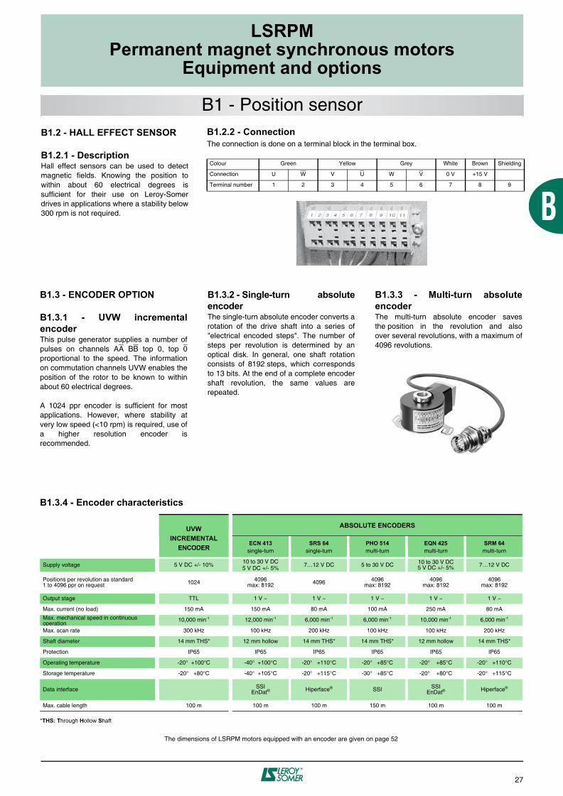
B1.2 - HALL EFFECT SENSOR
B1.2.1 - DescriptionHall effect sensors can be used to detectmagnetic fields. Knowing the position towithin about 60 electrical degrees issufficient for their use on Leroy-Somerdrives in applications where a stability below300 rpm is not required.
B1 - Position sensor
B1.3 - ENCODER OPTION
B1.3.1 - UVW incrementalencoderThis pulse generator supplies a number ofpulses on channels AA BB top 0, top 0proportional to the speed. The informationon commutation channels UVW enables theposition of the rotor to be known to withinabout 60 electrical degrees.
A 1024 ppr encoder is sufficient for mostapplications. However, where stability atvery low speed (<10 rpm) is required, use ofa higher resolution encoder isrecommended.
B1.3.2 - Single-turn absoluteencoderThe single-turn absolute encoder converts arotation of the drive shaft into a series of"electrical encoded steps". The number ofsteps per revolution is determined by anoptical disk. In general, one shaft rotationconsists of 8192 steps, which correspondsto 13 bits. At the end of a complete encodershaft revolution, the same values arerepeated.
B1.3.3 - Multi-turn absoluteencoderThe multi-turn absolute encoder savesthe position in the revolution and alsoover several revolutions, with a maximum of4096 revolutions.
B1.3.4 - Encoder characteristics
*THS: Through Hollow Shaft
The dimensions of LSRPM motors equipped with an encoder are given on page 52
UVW INCREMENTAL
ENCODER
ABSOLUTE ENCODERS
ECN 413single-turn
SRS 64single-turn
PHO 514multi-turn
EQN 425multi-turn
SRM 64multi-turn
Supply voltage 5 V DC +/- 10%10 to 30 V DC5 V DC +/- 5%
7…12 V DC 5 to 30 V DC 10 to 30 V DC5 V DC +/- 5% 7…12 V DC
Positions per revolution as standard1 to 4096 ppr on request 1024 4096
max: 8192 4096 4096max: 8192
4096max: 8192
4096max: 8192
Output stage TTL 1 V ~ 1 V ~ 1 V ~ 1 V ~ 1 V ~
Max. current (no load) 150 mA 150 mA 80 mA 100 mA 250 mA 80 mA
Max. mechanical speed in continuous operation
10,000 min-1 12,000 min-1 6,000 min-1 6,000 min-1 10,000 min-1 6,000 min-1
Max. scan rate 300 kHz 100 kHz 200 kHz 100 kHz 100 kHz 200 kHz
Shaft diameter 14 mm THS* 12 mm hollow 14 mm THS* 14 mm THS* 12 mm hollow 14 mm THS*
Protection IP65 IP65 IP65 IP65 IP65 IP65
Operating temperature -20° +100°C -40° +100°C -20° +110°C -20° +85°C -20° +85°C -20° +110°C
Storage temperature -20° +80°C -40° +105°C -20° +115°C -30° +85°C -20° +80°C -20° +115°C
Data interface SSIEnDat® Hiperface® SSI SSI
EnDat® Hiperface®
Max. cable length 100 m 100 m 100 m 150 m 100 m 100 m
B1.2.2 - ConnectionThe connection is done on a terminal block in the terminal box.
Colour Green Yellow Grey White Brown Shielding
Connection U W V U W V 0 V +15 V
Terminal number 1 2 3 4 5 6 7 8 9

28
LSRPMPermanent magnet synchronous motors
Equipment and options
LSRPM motors are self-cooled
(IC411) as standard
1 ± 10% for voltage, ± 2% for frequency.2 Protection index of the forced ventilation installed on the motor.
The dimensions of LSRPM motors equipped with forced ventilation are given on page 52
Motor type Supplyvoltage1
Consumption Protectionindex2
P (W) I (A)
LSRPM 90 to 132 single-phase230 or 400V
100 0.75/0.43 IP 55
LSRPM 160 to 280S3-phase
230/400V 50Hz254/460V 60Hz
1500.94/0.55 IP 55
LSRPM 280M and 3153-phase
230/400V 50Hz254/460V 60Hz
200 1.4/0.8 IP 55
LSRPM 315M3-phase
230/400V 50Hz254/460V 60Hz
750 3.6/2.1 IP 55
To keep the rated torque over the entirespeed range, forced ventilation may benecessary.
B2 - Forced ventilation
BlackW V
CP2
CP1
ZUBlue
Brown
Motor type
Capacitors
CP1 CP2
LSRPM 90 to 132
U = 230 V Power supply on U and WU = 400 V Power supply on V and W
3 mf 2 mf
SINGLE-PHASE FORCED VENTILATION, 230 or 400 V, for frame size < 132 3-PHASE FORCED VENTILATION for frame size > 132
1 SPEED – 2 VOLTAGES
L1 - L2 - L3
W2 U2 V2
L1 L2 L3
U1 V1 W1
W2 U2 V2
L1 L2 L3
U1 V1 W1

29
LSRPMPermanent magnet synchronous motors
Equipment and options
For peak voltages greater than 1500V,reinforced-insulation option is available.
B3.2 - REINFORCED INSULATIONOF THE MECHANICAL PARTSSame phenomena which affects the insulationsystem of a winding i.e. high switchingfrequencies and rate of rise of peak voltage,could affect the mechanical parts as well,particularly the rolling elements. These areassociated with inherent magnetic
assymmetries or with unbalanced excitation ofthe winding or combination of both. But, whena motor is fed via a Pulse Width Modulated(PWM), the situation is exacerbated and thiscould result in premature wear of bearings.
B3 - Reinforced insulation
Motor power supply signal
200 V/div. 0.5 μs/div
Voltage peak generatedat each pulse
Figure 1
LSRPM motors fitted with insulated
bearings are specified on page 58
--
If power is supplied via a PWM drive, highfrequency currents generated by the IGBToutput bridges of the drives, "attempt" tospread towards the drive and therefore flowthrough the stator and via earth where thelink between casing, machine chassis andearth is correctly made.
Otherwise, they will flow via the leastresistive path: end shields/bearings/shaft/machine coupled to the motor. In thesesituations, therefore, protection for thebearings must be provided.
For this reason, an "insulated bearing"option is available over the entire LSRPMrange from a frame size of 200.
Insulated bearing characteristics:For motors < 200 frame, insulated bearing isnot necessary because energy levelsgenerated are so low. But, if a particularspecification calls for it imperatvely, we willbe able to provide this option.
HF common modecurrents
MotorPWM drive
Standard motors in the LSRPM range arecompatible with power supplies with thefollowing characteristics:• U rms = 480 V max.• Value of voltage peaks generated at theterminals: 1500 V max.• Switching frequency: 2.5 kHz min.
However, they may be supplied under moresevere conditions if additional protection isprovided.
B3.1 - REINFORCED WINDINGINSULATIONThe main effect connected with supplyingpower via an electronic drive is overheatingof the motor due to the non-sinusoidalnature of the the output waveforms. Thisphenomena, combined with high frequencyrepetitive peak voltages genenerated at theleading and lagging edges of pulses in thesupply voltage waveform, can lead toaccelerated aging of the winding. (seeFigure 1).
30
LSRPMPermanent magnet synchronous motors
Equipment and options
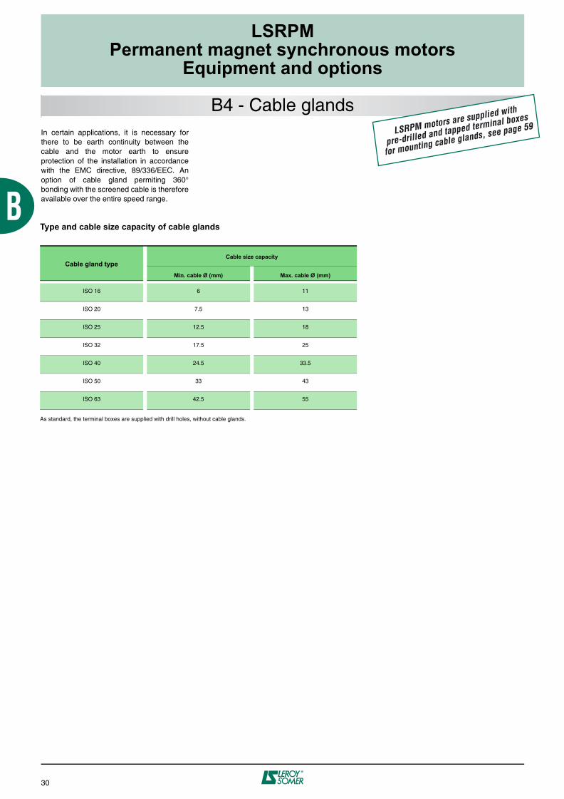
In certain applications, it is necessary forthere to be earth continuity between thecable and the motor earth to ensureprotection of the installation in accordancewith the EMC directive, 89/336/EEC. Anoption of cable gland permiting 360°bonding with the screened cable is thereforeavailable over the entire speed range.
B4 - Cable glandsLSRPM motors are supplied with
pre-drilled and tapped terminal boxes
for mounting cable glands, see page 59
Type and cable size capacity of cable glands
As standard, the terminal boxes are supplied with drill holes, without cable glands.
Cable gland typeCable size capacity
Min. cable Ø (mm) Max. cable Ø (mm)
ISO 16 6 11
ISO 20 7.5 13
ISO 25 12.5 18
ISO 32 17.5 25
ISO 40 24.5 33.5
ISO 50 33 43
ISO 63 42.5 55

31
LSRPMPermanent magnet synchronous motors
Equipment and options
B5 - Thermal protection LSRPM motors are fitted with
PTC sensors as standard
The motors are protected by the variablespeed drive, placed between the isolatingswitch and the motor.The variable speed drive helps to provide totalprotection of the motor against overloads.
LSRPM motors are fitted with PTC sensors inthe winding. As an option, specific thermalprotection sensors can be selected from thetable below.
It must be emphasized that under nocircumstances can these sensors beused to carry out direct regulation of themotor operating cycles.
Built-in indirect thermal protection
- NRT: Nominal running temperature- The NRTs are chosen according to the position of the sensor in the motor and the temperature rise class.* The number of devices relates to the winding protection.
Fitting thermal protection- PTO or PTF, in the control circuits- PTC, with associated relay, in the controlcircuits- PT 100 or Thermocouples, with associatedreading equipment or recorder, in thecontrol boards of installations for continuousmonitoring
Alarm and early warningAll protective equipment can be backed upby another type of protection (with adifferent normal running temperature, NRT).The first device will then act as an "earlywarning" (light or sound signals givenwithout shutting down the power circuits),and the second device will be the actualalarm (shutting down the power circuits).
Connection of PTC sensorsTerminal numbers: 10 and 11.
Type Operating principle Operating curve Breaking capacity (A) Protection providedMounting
Number of devices*
Normally closed thermal protection
PTO
Bimetallic strip, indirectly heated, with normally closed (NC) contact 2.5 A at 250 V
with cos 0.4
General monitoringfor non-transient
overloads
Mounting in controlcircuit
2 or 3 in range
Normally open thermal protection
PTF
Bimetallic strip, indirectly heated, with normally
open (NO) contact 2.5 A at 250 Vwith cos 0.4
General monitoringfor non-transient
overloads
Mounting in controlcircuit
2 or 3 in parallel
Positive temperature coefficient thermistor
PTC
Non-linear variable resistance, indirectly
heated 0General monitoring
for transient overloads
Mounted with associated relayin control circuit
3 in range
Temperature sensorKT
Resistance depends on the temperature of the
winding0
Continuous monitoringwith high accuracy
at key hot spots
Mounted in control boardswith associated reading equipment
(or recorder)
1 per hot spot
ThermocouplesT (T < 150°C)
Constantan copperK (T < 1000°C)
Copper/copper-nickel
Peltier effect 0Continuous monitoring
at regular intervalsat hot spots
Mounted in control boardswith associated reading equipment
(or recorder)
1 per hot spot
Platinum temperature sensorPT 100
Linear variable resistance, indirectly
heated0
Continuous monitoringwith high accuracy
at key hot spots
Mounted in control boardswith associated reading equipment
(or recorder)
1 per hot spot
I
O TNF
T
I
F TNF
T
R
TNF
T
R
T
V
T
R
T


LSRPMPermanent magnet synchronous motors
Electrical characteristics
33
PAGE
5500 range ...................................................................................... 34-35
4500 range ...................................................................................... 34-35
3600 range ...................................................................................... 36-37
3000 range ...................................................................................... 36-37
2400 range ...................................................................................... 38-39
1800 range ...................................................................................... 38-39
1500 range ...................................................................................... 40-41
900 range ........................................................................................ 40-41
750 range ........................................................................................ 42-43
375 range ........................................................................................ 42-43
The performances given are those of LSRPM motors used in conjunction with LEROY-SOMER drives.The values and tolerances conform to IEC 60034-1.
C1 - Characteristic data 34 to 43

34
LSRPMPermanent magnet synchronous motors
Electrical characteristics
C1 - Characteristic data
(1) Risk of demagnetisation above these values.
BASED ON INVERTER INPUT VOLTAGE OF 400V
Ratedpower
Rated speed
Rated torque
Ratedcurrent Efficiency (1) Max. torque/
Rated torque(1) Max. current/
Rated currentMomentof inertia Weight
Type PNkW
NN
min-1CNN.m
IN A %
MM/MN IM/IN Jkg.m2
IM B3kg
LSRPM 90 SL 6.9 5500 12 12.7 93.5 1.5 1.5 0.0032 14
LSRPM 90 L 8.6 5500 15 15.8 94 1.5 1.5 0.0051 17
LSRPM 100 L 10.4 5500 18 19 94 1.5 1.5 0.0066 19
LSRPM 100 L 12.1 5500 21 22 94.5 1.5 1.5 0.0078 24
LSRPM 100 L 13.8 5500 24 25 94.5 1.5 1.5 0.009 26
LSRPM 132 M 18.6 5500 32 35 94 1.5 1.5 0.0165 40
LSRPM 132 M 23 5500 40 44 94 1.5 1.5 0.0231 44
LSRPM 132 M 27 5500 47 52 94.5 1.5 1.5 0.0311 49
LSRPM 160 MP 35 5500 62 67 94.5 1.5 1.5 0.0418 60
LSRPM 160 MP 44 5500 76 82 95 1.5 1.5 0.0514 69
LSRPM 160 LR 52 5500 90 97 95 1.5 1.5 0.0626 79
LSRPM 200 L 70 5500 122 138 95.2 1.4 1.5 0.13 135
LSRPM 200 L 85 5500 148 169 95.6 1.4 1.5 0.15 145
LSRPM 200 L 100 5500 174 195 95.9 1.4 1.5 0.17 150
LSRPM 200 L1 140 5500 243 267 96.6 1.4 1.5 0.22 175
BASED ON INVERTER INPUT VOLTAGE OF 400V
Ratedpower
Rated speed
Rated torque
Ratedcurrent Efficiency (1) Max. torque/
Rated torque(1) Max. current/
Rated currentMomentof inertia Weight
Type PNkW
NN
min-1CNN.m
IN A %
MM/MN IM/IN Jkg.m2
IM B3kg
LSRPM 90 SL 6.8 4500 15 12.6 93.5 1.5 1.5 0.0032 14
LSRPM 90 L 8.5 4500 18 15.7 94 1.5 1.5 0.0051 17
LSRPM 100 L 10.2 4500 22 18.8 94 1.5 1.5 0.0066 19
LSRPM 100 L 12 4500 25 22 94.5 1.5 1.5 0.0078 24
LSRPM 100 L 13.7 4500 29 25 94.5 1.5 1.5 0.009 26
LSRPM 132 M 18.6 4500 39 35 94.5 1.5 1.5 0.0165 40
LSRPM 132 M 23 4500 49 44 94.5 1.5 1.5 0.0231 44
LSRPM 132 M 27 4500 58 51 95 1.5 1.5 0.0311 49
LSRPM 160 MP 35 4500 75 67 95 1.5 1.5 0.0418 60
LSRPM 160 MP 44 4500 93 81 95.5 1.5 1.5 0.0514 69
LSRPM 160 LR 52 4500 110 97 95.5 1.5 1.5 0.0626 79
LSRPM 200 L 65 4500 138 128 95.3 1.4 1.5 0.13 135
LSRPM 200 L 80 4500 170 157 95.7 1.4 1.5 0.15 145
LSRPM 200 L 100 4500 212 186 96.2 1.4 1.5 0.2 165
LSRPM 200 L1 120 4500 255 230 96.4 1.4 1.5 0.22 175
LSRPM 200 LU1 150 4500 318 288 97 1.4 1.5 0.26 190
LSRPM 225 SR1 170 4500 361 313 97.1 1.4 1.5 0.32 220
LSRPM 250 SE 230 4500 488 415 97.3 1.4 1.5 0.76 310
5500
range
4500
range

35
LSRPMPermanent magnet synchronous motors
Electrical characteristics
BASED ON INVERTER INPUT VOLTAGE OF 380V
BASED ON INVERTERINPUT VOLTAGE OF 415V
Ratedpower
Ratedspeed
Rated torque
Rated current Efficiency Rated
powerRatedspeed
Rated torque
Rated current Efficiency Moment
of inertia Weight
Type PNkW
NN
min-1CNN.m
IN A %
PNkW
NN
min-1CNN.m
IN A %
Jkg.m2
IM B3kg
LSRPM 90 SL 6.55 5225 12 12.7 93.5 6.9 5500 12 12.7 93.5 0.0032 14
LSRPM 90 L 8.17 5225 15 15.8 94 8.6 5500 15 15.8 94 0.0051 17
LSRPM 100 L 9.88 5225 18 19 94 10.4 5500 18 19 94 0.0066 19
LSRPM 100 L 11.5 5225 21 22 94.5 12.1 5500 21 22 94.5 0.0078 24
LSRPM 100 L 13.11 5225 24 25 94.5 13.8 5500 24 25 94.5 0.009 26
LSRPM 132 M 17.7 5225 32 35 94 18.6 5500 32 35 94 0.0165 40
LSRPM 132 M 21.8 5225 40 44 94 23 5500 40 44 94 0.0231 44
LSRPM 132 M 25.6 5225 47 52 94.5 27 5500 47 52 94.5 0.0311 49
LSRPM 160 MP 33 5225 62 67 94.5 35 5500 62 67 94.5 0.0418 60
LSRPM 160 MP 42 5225 76 82 95 44 5500 76 82 95 0.0514 69
LSRPM 160 LR 49 5225 90 97 95 52 5500 90 97 95 0.0626 79
LSRPM 200 L 67 5225 122 138 95.2 70 5500 122 138 95.2 0.13 135
LSRPM 200 L 81 5225 148 169 95.6 85 5500 148 169 95.6 0.15 145
LSRPM 200 L 95 5225 174 195 95.9 100 5500 174 195 95.9 0.17 150
LSRPM 200 L1 133 5225 243 267 96.6 140 5500 243 267 96.6 0.22 175
BASED ON INVERTER INPUT VOLTAGE OF 380V
BASED ON INVERTERINPUT VOLTAGE OF 415V
Ratedpower
Ratedspeed
Rated torque
Rated current Efficiency Rated
powerRatedspeed
Rated torque
Rated current Efficiency Moment
of inertia Weight
Type PNkW
NN
min-1CNN.m
IN A %
PNkW
NN
min-1CNN.m
IN A %
Jkg.m2
IM B3kg
LSRPM 90 SL 6.4 4275 15 12.6 93.5 6.8 4500 15 12.6 93.5 0.0032 14
LSRPM 90 L 8 4275 18 15.7 94 8.5 4500 18 15.7 94 0.0051 17
LSRPM 100 L 9.7 4275 22 18.8 94 10.2 4500 22 18.8 94 0.0066 19
LSRPM 100 L 11.4 4275 25 22 94.5 12 4500 25 22 94.5 0.0078 24
LSRPM 100 L 13 4275 29 25 94.5 13.7 4500 29 25 94.5 0.009 26
LSRPM 132 M 17.7 4275 39 35 94.5 18.6 4500 39 35 94.5 0.0165 40
LSRPM 132 M 21.8 4275 49 44 94.5 23 4500 49 44 94.5 0.0231 44
LSRPM 132 M 25.6 4275 58 51 95 27 4500 58 51 95 0.0311 49
LSRPM 160 MP 33 4275 75 67 95 35 4500 75 67 95 0.0418 60
LSRPM 160 MP 42 4275 93 81 95.5 44 4500 93 81 95.5 0.0514 69
LSRPM 160 LR 49 4275 110 97 95.5 52 4500 110 97 95.5 0.0626 79
LSRPM 200 L 62 4275 138 128 95.3 65 4500 138 128 95.3 0.13 135
LSRPM 200 L 76 4275 170 157 95.7 80 4500 170 157 95.7 0.15 145
LSRPM 200 L 95 4275 212 186 96.2 100 4500 212 186 96.2 0.2 165
LSRPM 200 L1 114 4275 255 230 96.4 120 4500 255 230 96.4 0.22 175
LSRPM 200 LU1 142 4275 318 288 97 150 4500 318 288 97 0.26 190
LSRPM 225 SR1 162 4275 361 313 97.1 170 4500 361 313 97.1 0.32 220
LSRPM 250 SE 219 4275 488 415 97.3 230 4500 488 415 97.3 0.76 310
C1 - Characteristic data
5500
range
4500
range

36
LSRPMPermanent magnet synchronous motors
Electrical characteristics
C1 - Characteristic data
(1) Risk of demagnetisation above these values.
BASED ON INVERTER INPUT VOLTAGE OF 400V
Ratedpower
Rated speed
Rated torque
Ratedcurrent Efficiency (1) Max. torque/
Rated torque(1) Max. current/
Rated currentMomentof inertia Weight
Type PNkW
NN
min-1CNN.m
IN A %
MM/MN IM/IN Jkg.m2
IM B3kg
LSRPM 90 SL 6.4 3600 17 11.9 93 1.5 1.5 0.0032 14LSRPM 90 L 8 3600 21 14.8 93.5 1.5 1.5 0.0051 17LSRPM 100 L 9.6 3600 26 17.6 94 1.5 1.5 0.0066 19LSRPM 100 L 11.2 3600 30 21 94 1.5 1.5 0.0078 24LSRPM 100 L 12.8 3600 34 23 94.5 1.5 1.5 0.009 26LSRPM 132 M 17.6 3600 47 33 94.5 1.5 1.5 0.0165 40LSRPM 132 M 22 3600 58 41 94.5 1.5 1.5 0.0231 44LSRPM 132 M 26 3600 69 48 95 1.5 1.5 0.0311 49LSRPM 160 MP 34 3600 89 63 95 1.5 1.5 0.0418 60LSRPM 160 MP 41 3600 110 77 95.5 1.5 1.5 0.0514 69LSRPM 160 LR 49 3600 130 91 95.5 1.5 1.5 0.0626 79LSRPM 200 L 50 3600 133 105 95 1.35 1.45 0.13 135LSRPM 200 L 70 3600 186 140 95.8 1.35 1.45 0.17 150LSRPM 200 L 85 3600 225 163 96 1.35 1.45 0.22 175LSRPM 200 L1 105 3600 279 201 96.7 1.35 1.45 0.24 180LSRPM 200 LU1 125 3600 332 241 96.8 1.35 1.45 0.26 190LSRPM 250 SE 165 3600 438 311 97 1.35 1.45 0.57 265LSRPM 250 SE 190 3600 504 363 97.4 1.35 1.45 0.65 285LSRPM 280 SC 240 3600 637 450 97.4 1.35 1.45 0.84 330LSRPM 280 SD 290 3600 769 540 97.5 1.35 1.45 1 380LSRPM 280 MK 325 3600 862 653 97.2 1.35 1.45 2.1 615LSRPM 315 SP 390 3600 1035 765 97.4 1.35 1.45 2.5 670
BASED ON INVERTER INPUT VOLTAGE OF 400V
Ratedpower
Rated speed
Rated torque
Ratedcurrent Efficiency (1) Max. torque/
Rated torque(1) Max. current/
Rated currentMomentof inertia Weight
Type PNkW
NN
min-1CNN.m
IN A %
MM/MN IM/IN Jkg.m2
IM B3kg
LSRPM 90 SL 5.8 3000 19 11 91.5 1.5 1.5 0.0032 14LSRPM 90 L 7.3 3000 23 13.5 93 1.5 1.5 0.0051 17LSRPM 100 L 8.7 3000 28 16.2 93 1.5 1.5 0.0066 19LSRPM 100 L 10.2 3000 32 18.8 93.5 1.5 1.5 0.0078 24LSRPM 100 L 11.6 3000 37 21 93.5 1.5 1.5 0.009 26LSRPM 132 M 15.8 3000 50 30 93 1.5 1.5 0.0165 40LSRPM 132 M 19.7 3000 63 38 93.5 1.5 1.5 0.0231 44LSRPM 132 M 23 3000 74 44 94 1.5 1.5 0.0311 49LSRPM 160 MP 30 3000 96 57 94.5 1.5 1.5 0.0418 60LSRPM 160 MP 37 3000 118 69 95 1.5 1.5 0.0514 69LSRPM 160 LR 44 3000 140 82 95 1.5 1.5 0.0626 79LSRPM 200 L 50 3000 159 102 95.1 1.35 1.45 0.13 135LSRPM 200 L 65 3000 207 129 95.8 1.35 1.45 0.17 150LSRPM 200 L 85 3000 271 166 96.2 1.35 1.45 0.22 175LSRPM 200 L1 105 3000 334 209 96.6 1.35 1.45 0.24 180LSRPM 225 ST1 115 3000 366 230 96.7 1.35 1.45 0.26 190LSRPM 250 SE 145 3000 462 279 97.2 1.35 1.45 0.57 265LSRPM 250 ME 170 3000 541 338 97.3 1.35 1.45 0.65 285LSRPM 280 SC 220 3000 700 428 97.5 1.35 1.45 0.84 330LSRPM 280 MD 260 3000 828 495 97.6 1.35 1.45 1 380LSRPM 280 MK 290 3000 923 579 97.4 1.35 1.45 2.1 615LSRPM 315 SP 340 3000 1082 656 97.6 1.35 1.45 2.5 670
5500
range3600
range
4500
range3000
range

37
LSRPMPermanent magnet synchronous motors
Electrical characteristics
C1 - Characteristic data
BASED ON INVERTER INPUT VOLTAGE OF 380V
BASED ON INVERTERINPUT VOLTAGE OF 415V
Ratedpower
Ratedspeed
Rated torque
Rated current Efficiency Rated
powerRatedspeed
Rated torque
Rated current Efficiency Moment
of inertia Weight
Type PNkW
NN
min-1CNN.m
IN A %
PNkW
NN
min-1CNN.m
IN A %
Jkg.m2
IM B3kg
LSRPM 90 SL 6.08 3420 17 11.9 93 6.4 3600 17 11.9 93 0.0032 14LSRPM 90 L 7.6 3420 21 14.8 93.5 8 3600 21 14.8 93.5 0.0051 17LSRPM 100 L 9.12 3420 26 17.6 94 9.6 3600 26 17.6 94 0.0066 19LSRPM 100 L 10.64 3420 30 21 94 11.2 3600 30 21 94 0.0078 24LSRPM 100 L 12.16 3420 34 23 94.5 12.8 3600 34 23 94.5 0.009 26LSRPM 132 M 16.7 3420 47 33 94.5 17.6 3600 47 33 94.5 0.0165 40LSRPM 132 M 20.9 3420 58 41 94.5 22 3600 58 41 94.5 0.0231 44LSRPM 132 M 24.7 3420 69 48 95 26 3600 69 48 95 0.0311 49LSRPM 160 MP 32 3420 89 63 95 34 3600 89 63 95 0.0418 60LSRPM 160 MP 39 3420 110 77 95.5 41 3600 110 77 95.5 0.0514 69LSRPM 160 LR 47 3420 130 91 95.5 49 3600 130 91 95.5 0.0626 79LSRPM 200 L 48 3420 133 105 95 50 3600 133 105 95 0.13 135LSRPM 200 L 67 3420 186 140 95.8 70 3600 186 140 95.8 0.17 150LSRPM 200 L 80 3420 225 163 96 85 3600 225 163 96 0.22 175LSRPM 200 L1 100 3420 279 201 96.7 105 3600 279 201 96.7 0.24 180LSRPM 200 LU1 119 3420 332 241 96.8 125 3600 332 241 96.8 0.26 190LSRPM 250 SE 157 3420 438 311 97 165 3600 438 311 97 0.57 265LSRPM 250 SE 180 3420 504 363 97.4 190 3600 504 363 97.4 0.65 285LSRPM 280 SC 228 3420 637 450 97.4 240 3600 637 450 97.4 0.84 330LSRPM 280 SD 275 3420 769 540 97.5 290 3600 769 540 97.5 1 380LSRPM 280 MK 309 3420 862 653 97.2 325 3600 862 653 97.2 2.1 615LSRPM 315 SP 370 3420 1035 765 97.4 390 3600 1035 765 97.4 2.5 670
BASED ON INVERTER INPUT VOLTAGE OF 380V
BASED ON INVERTERINPUT VOLTAGE OF 415V
Ratedpower
Ratedspeed
Rated torque
Rated current Efficiency Rated
powerRatedspeed
Rated torque
Rated current Efficiency Moment
of inertia Weight
Type PNkW
NN
min-1CNN.m
IN A %
PNkW
NN
min-1CNN.m
IN A %
Jkg.m2
IM B3kg
LSRPM 90 SL 5.51 2850 19 11 91.5 5.8 3000 19 11 91.5 0.0032 14LSRPM 90 L 6.93 2850 23 13.5 93 7.3 3000 23 13.5 93 0.0051 17LSRPM 100 L 8.26 2850 28 16.2 93 8.7 3000 28 16.2 93 0.0066 19LSRPM 100 L 9.69 2850 32 18.8 93.5 10.2 3000 32 18.8 93.5 0.0078 24LSRPM 100 L 11 2850 37 21 93.5 11.6 3000 37 21 93.5 0.009 26LSRPM 132 M 15 2850 50 30 93 15.8 3000 50 30 93 0.0165 40LSRPM 132 M 18.7 2850 63 38 93.5 19.7 3000 63 38 93.5 0.0231 44LSRPM 132 M 21.8 2850 74 44 94 23 3000 74 44 94 0.0311 49LSRPM 160 MP 28.5 2850 96 57 94.5 30 3000 96 57 94.5 0.0418 60LSRPM 160 MP 35 2850 118 69 95 37 3000 118 69 95 0.0514 69LSRPM 160 LR 42 2850 140 82 95 44 3000 140 82 95 0.0626 79LSRPM 200 L 47 2850 159 102 95.1 50 3000 159 102 95.1 0.13 135LSRPM 200 L 62 2850 207 129 95.8 65 3000 207 129 95.8 0.17 150LSRPM 200 L 81 2850 271 166 96.2 85 3000 271 166 96.2 0.22 175LSRPM 200 L1 100 2850 334 209 96.6 105 3000 334 209 96.6 0.24 180LSRPM 225 ST1 109 2850 366 230 96.7 115 3000 366 230 96.7 0.26 190LSRPM 250 SE 138 2850 462 279 97.2 145 3000 462 279 97.2 0.57 265LSRPM 250 ME 161 2850 541 338 97.3 170 3000 541 338 97.3 0.65 285LSRPM 280 SC 209 2850 700 428 97.5 220 3000 700 428 97.5 0.84 330LSRPM 280 MD 247 2850 828 495 97.6 260 3000 828 495 97.6 1 380LSRPM 280 MK 275 2850 923 579 97.4 290 3000 923 579 97.4 2.1 615LSRPM 315 SP 323 2850 1082 656 97.6 340 3000 1082 656 97.6 2.5 670
4500
range3000
range
5500
range3600
range
38
LSRPMPermanent magnet synchronous motors
Electrical characteristics
C1 - Characteristic data
(1) Risk of demagnetisation above these values.
BASED ON INVERTER INPUT VOLTAGE OF 400V
Ratedpower
Rated speed
Rated torque
Ratedcurrent Efficiency (1) Max. torque/
Rated torque(1) Max. current/
Rated currentMomentof inertia Weight
Type PNkW
NN
min-1CNN.m
IN A %
MM/MN IM/IN Jkg.m2
IM B3kg
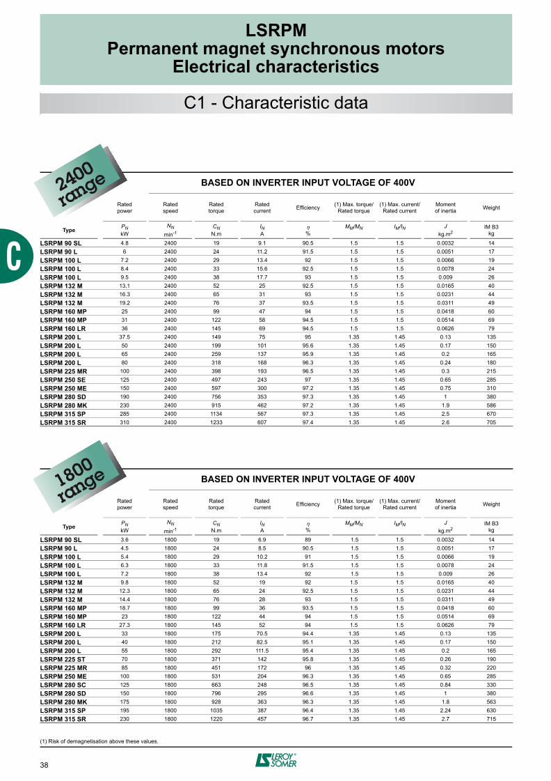
LSRPM 90 SL 4.8 2400 19 9.1 90.5 1.5 1.5 0.0032 14LSRPM 90 L 6 2400 24 11.2 91.5 1.5 1.5 0.0051 17LSRPM 100 L 7.2 2400 29 13.4 92 1.5 1.5 0.0066 19LSRPM 100 L 8.4 2400 33 15.6 92.5 1.5 1.5 0.0078 24LSRPM 100 L 9.5 2400 38 17.7 93 1.5 1.5 0.009 26LSRPM 132 M 13.1 2400 52 25 92.5 1.5 1.5 0.0165 40LSRPM 132 M 16.3 2400 65 31 93 1.5 1.5 0.0231 44LSRPM 132 M 19.2 2400 76 37 93.5 1.5 1.5 0.0311 49LSRPM 160 MP 25 2400 99 47 94 1.5 1.5 0.0418 60LSRPM 160 MP 31 2400 122 58 94.5 1.5 1.5 0.0514 69LSRPM 160 LR 36 2400 145 69 94.5 1.5 1.5 0.0626 79LSRPM 200 L 37.5 2400 149 75 95 1.35 1.45 0.13 135LSRPM 200 L 50 2400 199 101 95.6 1.35 1.45 0.17 150LSRPM 200 L 65 2400 259 137 95.9 1.35 1.45 0.2 165LSRPM 200 L 80 2400 318 168 96.3 1.35 1.45 0.24 180LSRPM 225 MR 100 2400 398 193 96.5 1.35 1.45 0.3 215LSRPM 250 SE 125 2400 497 243 97 1.35 1.45 0.65 285LSRPM 250 ME 150 2400 597 300 97.2 1.35 1.45 0.75 310LSRPM 280 SD 190 2400 756 353 97.3 1.35 1.45 1 380LSRPM 280 MK 230 2400 915 462 97.2 1.35 1.45 1.9 586LSRPM 315 SP 285 2400 1134 567 97.3 1.35 1.45 2.5 670LSRPM 315 SR 310 2400 1233 607 97.4 1.35 1.45 2.6 705
BASED ON INVERTER INPUT VOLTAGE OF 400V
Ratedpower
Rated speed
Rated torque
Ratedcurrent Efficiency (1) Max. torque/
Rated torque(1) Max. current/
Rated currentMomentof inertia Weight
Type PNkW
NN
min-1CNN.m
IN A %
MM/MN IM/IN Jkg.m2
IM B3kg
LSRPM 90 SL 3.6 1800 19 6.9 89 1.5 1.5 0.0032 14LSRPM 90 L 4.5 1800 24 8.5 90.5 1.5 1.5 0.0051 17LSRPM 100 L 5.4 1800 29 10.2 91 1.5 1.5 0.0066 19LSRPM 100 L 6.3 1800 33 11.8 91.5 1.5 1.5 0.0078 24LSRPM 100 L 7.2 1800 38 13.4 92 1.5 1.5 0.009 26LSRPM 132 M 9.8 1800 52 19 92 1.5 1.5 0.0165 40LSRPM 132 M 12.3 1800 65 24 92.5 1.5 1.5 0.0231 44LSRPM 132 M 14.4 1800 76 28 93 1.5 1.5 0.0311 49LSRPM 160 MP 18.7 1800 99 36 93.5 1.5 1.5 0.0418 60LSRPM 160 MP 23 1800 122 44 94 1.5 1.5 0.0514 69LSRPM 160 LR 27.3 1800 145 52 94 1.5 1.5 0.0626 79LSRPM 200 L 33 1800 175 70.5 94.4 1.35 1.45 0.13 135LSRPM 200 L 40 1800 212 82.5 95.1 1.35 1.45 0.17 150LSRPM 200 L 55 1800 292 111.5 95.4 1.35 1.45 0.2 165LSRPM 225 ST 70 1800 371 142 95.8 1.35 1.45 0.26 190LSRPM 225 MR 85 1800 451 172 96 1.35 1.45 0.32 220LSRPM 250 ME 100 1800 531 204 96.3 1.35 1.45 0.65 285LSRPM 280 SC 125 1800 663 248 96.5 1.35 1.45 0.84 330LSRPM 280 SD 150 1800 796 295 96.6 1.35 1.45 1 380LSRPM 280 MK 175 1800 928 363 96.3 1.35 1.45 1.8 563LSRPM 315 SP 195 1800 1035 387 96.4 1.35 1.45 2.24 630LSRPM 315 SR 230 1800 1220 457 96.7 1.35 1.45 2.7 715
2400
range
1800
range

39
LSRPMPermanent magnet synchronous motors
Electrical characteristics
BASED ON INVERTER INPUT VOLTAGE OF 380V
BASED ON INVERTERINPUT VOLTAGE OF 415V
Ratedpower
Ratedspeed
Rated torque
Rated current Efficiency Rated
powerRatedspeed
Rated torque
Rated current Efficiency Moment
of inertia Weight
Type PNkW
NN
min-1CNN.m
IN A %
PNkW
NN
min-1CNN.m
IN A %
Jkg.m2
IM B3kg
LSRPM 90 SL 4.56 2280 19 9.1 90.5 4.8 2400 19 9.1 90.5 0.0032 14LSRPM 90 L 5.7 2280 24 11.2 91.5 6 2400 24 11.2 91.5 0.0051 17LSRPM 100 L 6.84 2280 29 13.4 92 7.2 2400 29 13.4 92 0.0066 19LSRPM 100 L 7.98 2280 33 15.6 92.5 8.4 2400 33 15.6 92.5 0.0078 24LSRPM 100 L 9 2280 38 17.7 93 9.5 2400 38 17.7 93 0.009 26LSRPM 132 M 12.4 2280 52 25 92 13.1 2400 52 25 92.5 0.0165 40LSRPM 132 M 15.5 2280 65 31 92.5 16.3 2400 65 31 93 0.0231 44LSRPM 132 M 18.2 2280 76 37 93.5 19.2 2400 76 37 93.5 0.0311 49LSRPM 160 MP 23.7 2280 99 47 94 25 2400 99 47 94 0.0418 60LSRPM 160 MP 29.4 2280 122 58 94.5 31 2400 122 58 94.5 0.0514 69LSRPM 160 LR 34 2280 145 69 94.5 36 2400 145 69 94.5 0.0626 79LSRPM 200 L 35 2280 149 75 95 37.5 2400 149 75 95 0.13 135LSRPM 200 L 47 2280 199 101 95.6 50 2400 199 101 95.6 0.17 150LSRPM 200 L 62 2280 259 137 95.9 65 2400 259 137 95.9 0.2 165LSRPM 200 L 76 2280 318 168 96.3 80 2400 318 168 96.3 0.24 180LSRPM 225 MR 95 2280 398 193 96.5 100 2400 398 193 96.5 0.3 215LSRPM 250 SE 119 2280 497 243 97 125 2400 497 243 97 0.65 285LSRPM 250 ME 142 2280 597 300 97.2 150 2400 597 300 97.2 0.75 310LSRPM 280 SD 180 2280 756 353 97.3 190 2400 756 353 97.3 1 380LSRPM 280 MK 218 2280 915 462 97.2 230 2400 915 462 97.2 1.9 586LSRPM 315 SP 271 2280 1134 567 97.3 285 2400 1134 567 97.3 2.5 670LSRPM 315 SR 294 2280 1233 607 97.4 310 2400 1233 607 97.4 2.6 705
BASED ON INVERTER INPUT VOLTAGE OF 380V
BASED ON INVERTERINPUT VOLTAGE OF 415V
Ratedpower
Ratedspeed
Rated torque
Rated current Efficiency Rated
powerRatedspeed
Rated torque
Rated current Efficiency Moment
of inertia Weight
Type PNkW
NN
min-1CNN.m
IN A %
PNkW
NN
min-1CNN.m
IN A %
Jkg.m2
IM B3kg
LSRPM 90 SL 3.42 1710 19 6.9 89 3.6 1800 19 6.9 89 0.0032 14LSRPM 90 L 4.27 1710 24 8.5 90.5 4.5 1800 24 8.5 90.5 0.0051 17LSRPM 100 L 5.13 1710 29 10.2 91 5.4 1800 29 10.2 91 0.0066 19LSRPM 100 L 5.98 1710 33 11.8 91.5 6.3 1800 33 11.8 91.5 0.0078 24LSRPM 100 L 6.84 1710 38 13.4 92 7.2 1800 38 13.4 92 0.009 26LSRPM 132 M 9.3 1710 52 19 92 9.8 1800 52 19 92 0.0165 40LSRPM 132 M 11.7 1710 65 24 92.5 12.3 1800 65 24 92.5 0.0231 44LSRPM 132 M 13.7 1710 76 28 93 14.4 1800 76 28 93 0.0311 49LSRPM 160 MP 17.7 1710 99 36 93.5 18.7 1800 99 36 93.5 0.0418 60LSRPM 160 MP 21.8 1710 122 44 94 23 1800 122 44 94 0.0514 69LSRPM 160 LR 25.9 1710 145 52 94 27.3 1800 145 52 94 0.0626 79LSRPM 200 L 31 1710 175 70.5 94.4 33 1800 175 70.5 94.4 0.13 135LSRPM 200 L 38 1710 212 82.5 95.1 40 1800 212 82.5 95.1 0.17 150LSRPM 200 L 52 1710 292 111.5 95.4 55 1800 292 111.5 95.4 0.2 165LSRPM 225 ST 66 1710 371 142 95.8 70 1800 371 142 95.8 0.26 190LSRPM 225 MR 81 1710 451 172 96 85 1800 451 172 96 0.32 220LSRPM 250 ME 95 1710 531 204 96.3 100 1800 531 204 96.3 0.65 285LSRPM 280 SC 119 1710 663 248 96.5 125 1800 663 248 96.5 0.84 330LSRPM 280 SD 142 1710 796 295 96.6 150 1800 796 295 96.6 1 380LSRPM 280 MK 166 1710 928 363 96.3 175 1800 928 363 96.3 1.8 563LSRPM 315 SP 185 1710 1035 387 96.4 195 1800 1035 387 96.4 2.24 630LSRPM 315 SR 218 1710 1220 457 96.7 230 1800 1220 457 96.7 2.7 715
C1 - Characteristic data
2400
range
1800
range

40
LSRPMPermanent magnet synchronous motors
Electrical characteristics
(1) Risk of demagnetisation above these values.
BASED ON INVERTER INPUT VOLTAGE OF 400V
Ratedpower
Ratedspeed
Ratedtorque
Ratedcurrent Efficiency (1) Max. torque/
Rated torque(1) Max. current/
Rated currentMomentof inertia Weight
Type PNkW
NN
min-1CNN.m
IN A %
MM/MN IM/IN Jkg.m2
IM B3kg
LSRPM 90 SL 3 1500 19 5.9 87 1.5 1.5 0.0032 14LSRPM 90 L 3.7 1500 24 7.2 89 1.5 1.5 0.0051 17LSRPM 100 L 4.5 1500 29 8.6 90 1.5 1.5 0.0066 19LSRPM 100 L 5.2 1500 33 9.9 91 1.5 1.5 0.0078 24LSRPM 100 L 6 1500 38 11.2 91.5 1.5 1.5 0.009 26LSRPM 132 M 8.2 1500 52 16 91 1.5 1.5 0.0165 40LSRPM 132 M 10.2 1500 65 19.9 91.5 1.5 1.5 0.0231 44LSRPM 132 M 12 1500 76 23 92 1.5 1.5 0.0311 49LSRPM 160 MP 15.6 1500 99 30 92.5 1.5 1.5 0.0418 60LSRPM 160 MP 19.2 1500 122 37 93 1.5 1.5 0.0514 69LSRPM 160 LR 22.8 1500 145 43 93.5 1.5 1.5 0.0626 79LSRPM 200 L 25 1500 159 51.5 94 1.35 1.45 0.13 135LSRPM 200 L 33 1500 210 67 94.8 1.35 1.45 0.17 150LSRPM 200 L 40 1500 255 78.5 95.2 1.35 1.45 0.2 165LSRPM 200 LU 55 1500 350 105 95.5 1.35 1.45 0.26 190LSRPM 225 MR 70 1500 446 142 95.9 1.35 1.45 0.32 220LSRPM 250 ME 85 1500 541 169 96.4 1.35 1.45 0.65 285LSRPM 280 SC 105 1500 668 216 96.5 1.35 1.45 0.84 330LSRPM 280 SD 125 1500 796 236 96.6 1.35 1.45 1 380LSRPM 280 MK 145 1500 923 294 96.2 1.35 1.45 1.8 563LSRPM 315 SP 175 1500 1114 355 96.5 1.35 1.45 2.24 630LSRPM 315 MR 220 1500 1401 438 96.9 1.35 1.45 2.7 715
BASED ON INVERTER INPUT VOLTAGE OF 400V
Ratedpower
Rated speed
Rated torque
Ratedcurrent Efficiency (1) Max. torque/
Rated torque(1) Max. current/
Rated currentMomentof inertia Weight
Type PNkW
NN
min-1CNN.m
IN A %
MM/MN IM/IN Jkg.m2
IM B3kg
LSRPM 90 SL 1.8 900 19 3.8 82 1.5 1.5 0.0032 14
LSRPM 90 L 2.2 900 24 4.6 84 1.5 1.5 0.0051 17LSRPM 100 L 2.7 900 29 5.4 85 1.5 1.5 0.0066 19LSRPM 100 L 3.1 900 33 6.2 87 1.5 1.5 0.0078 24LSRPM 100 L 3.6 900 38 7 88 1.5 1.5 0.009 26LSRPM 132 M 4.9 900 52 9.9 88 1.5 1.5 0.0165 40LSRPM 132 M 6.1 900 65 12.3 89 1.5 1.5 0.0231 44LSRPM 132 M 7.2 900 76 14.3 90 1.5 1.5 0.0311 49LSRPM 160 MP 9.4 900 99 18.4 90.5 1.5 1.5 0.0418 60LSRPM 160 MP 11.5 900 122 23 91 1.5 1.5 0.0514 69LSRPM 160 LR 13.7 900 145 27 91 1.5 1.5 0.0626 79LSRPM 200 L 15 900 159 33.5 90.6 1.35 1.45 0.13 135LSRPM 200 L 20 900 212 42.5 91.6 1.35 1.45 0.17 150LSRPM 200 L 25 900 265 50.2 92.3 1.35 1.45 0.2 165LSRPM 200 LU 33 900 350 65 92.9 1.35 1.45 0.26 190LSRPM 250 SE 40 900 424 76 95.5 1.35 1.45 0.54 250LSRPM 250 ME 50 900 531 98 95.8 1.35 1.45 0.65 285LSRPM 280 SD 60 900 637 112 96.2 1.35 1.45 0.92 350LSRPM 280 SD 75 900 796 145 96.3 1.35 1.45 1 380LSRPM 280 MK 85 900 902 175 95.9 1.35 1.45 1.67 540LSRPM 315 SP 100 900 1061 207 96.2 1.35 1.45 2.1 620LSRPM 315 MR 130 900 1379 265 96.6 1.35 1.45 2.6 705
1500
range
900range
C1 - Characteristic data

41
LSRPMPermanent magnet synchronous motors
Electrical characteristics
BASED ON INVERTER INPUT VOLTAGE OF 380V
BASED ON INVERTERINPUT VOLTAGE OF 415V
Ratedpower
Ratedspeed
Rated torque
Rated current Efficiency Rated
powerRatedspeed
Rated torque
Rated current Efficiency Moment
of inertia Weight
Type PNkW
NN
min-1CNN.m
IN A %
PNkW
NN
min-1CNN.m
IN A %
Jkg.m2
IM B3kg
LSRPM 90 SL 2.85 1425 19 5.9 87 2.85 1425 19 5.9 87 0.0032 14LSRPM 90 L 3.51 1425 24 7.2 89 3.51 1425 24 7.2 89 0.0051 17LSRPM 100 L 4.27 1425 29 8.6 90 4.27 1425 29 8.6 90 0.0066 19LSRPM 100 L 4.94 1425 33 9.9 91 4.94 1425 33 9.9 91 0.0078 24LSRPM 100 L 5.7 1425 38 11.2 91.5 5.7 1425 38 11.2 91.5 0.009 26LSRPM 132 M 7.8 1425 52 16 91 8.2 1500 52 16 91 0.0165 40LSRPM 132 M 9.7 1425 65 19.9 91.5 10.2 1500 65 19.9 91.5 0.0231 44LSRPM 132 M 11.4 1425 76 23 92 12 1500 76 23 92 0.0311 49LSRPM 160 MP 14.8 1425 99 30 92.5 15.6 1500 99 30 92.5 0.0418 60LSRPM 160 MP 18.2 1425 122 37 93 19.2 1500 122 37 93 0.0514 69LSRPM 160 LR 21.6 1425 145 43 93.5 22.8 1500 145 43 93.5 0.0626 79LSRPM 200 L 23.8 1425 159 51.5 94 25 1500 159 51.5 94 0.13 135LSRPM 200 L 31 1425 210 67 94.8 33 1500 210 67 94.8 0.17 150LSRPM 200 L 38 1425 255 78.5 95.2 40 1500 255 78.5 95.2 0.2 165LSRPM 200 LU 52 1425 350 105 95.5 55 1500 350 105 95.5 0.26 190LSRPM 225 MR 66 1425 446 142 95.9 70 1500 446 142 95.9 0.32 220LSRPM 250 ME 81 1425 541 169 96.4 85 1500 541 169 96.4 0.65 285LSRPM 280 SC 100 1425 668 216 96.5 105 1500 668 216 96.5 0.84 330LSRPM 280 SD 119 1425 796 236 96.6 125 1500 796 236 96.6 1 380LSRPM 280 MK 138 1425 923 294 96.2 145 1500 923 294 96.2 1.8 563LSRPM 315 SP 166 1425 1114 355 96.5 175 1500 1114 355 96.5 2.24 630LSRPM 315 MR 209 1425 1401 438 96.9 220 1500 1401 438 96.9 2.7 715
BASED ON INVERTER INPUT VOLTAGE OF 380V
BASED ON INVERTERINPUT VOLTAGE OF 415V
Ratedpower
Ratedspeed
Rated torque
Rated current Efficiency Rated
powerRatedspeed
Rated torque
Rated current Efficiency Moment
of inertia Weight
Type PNkW
NN
min-1CNN.m
IN A %
PNkW
NN
min-1CNN.m
IN A %
Jkg.m2
IM B3kg
LSRPM 90 SL 1.71 855 19 3.8 82 1.8 900 19 3.8 82 0.0032 14LSRPM 90 L 2.09 855 24 4.6 84 2.2 900 24 4.6 84 0.0051 17LSRPM 100 L 2.56 855 29 5.4 85 2.7 900 29 5.4 85 0.0066 19LSRPM 100 L 2.94 855 33 6.2 87 3.1 900 33 6.2 87 0.0078 24LSRPM 100 L 3.42 855 38 7 88 3.6 900 38 7 88 0.009 26LSRPM 132 M 4.6 855 52 9.9 88 4.9 900 52 9.9 88 0.0165 40LSRPM 132 M 5.8 855 65 12.3 89 6.1 900 65 12.3 89 0.0231 44LSRPM 132 M 6.8 855 76 14.3 90 7.2 900 76 14.3 90 0.0311 49LSRPM 160 MP 8.9 855 99 18.4 90.5 9.4 900 99 18.3 91 0.0418 60LSRPM 160 MP 10.9 855 122 23 91 11.5 900 122 22 91.5 0.0514 69LSRPM 160 LR 13 855 145 27 91 13.7 900 145 27 91.5 0.0626 79LSRPM 200 L 14.2 855 159 33.5 90.6 15 900 159 33.5 90.6 0.13 135LSRPM 200 L 19 855 212 42.5 91.6 20 900 212 42.5 91.6 0.17 150LSRPM 200 L 24 855 265 50.2 92.3 25 900 265 50.2 92.3 0.2 165LSRPM 200 LU 31 855 350 65 92.9 33 900 350 65 92.9 0.26 190LSRPM 250 SE 38 855 424 76 95.5 40 900 424 76 95.5 0.54 250LSRPM 250 ME 47 855 531 98 95.8 50 900 531 98 95.8 0.65 285LSRPM 280 SD 57 855 637 112 96.2 60 900 637 112 96.2 0.92 350LSRPM 280 SD 71 855 796 145 96.3 75 900 796 145 96.3 1 380LSRPM 280 MK 81 855 902 175 95.9 85 900 902 175 95.9 1.67 540LSRPM 315 SP 95 855 1061 207 96.2 100 900 1061 207 96.2 2.1 620LSRPM 315 MR 123 855 1379 265 96.6 130 900 1379 265 96.6 2.6 705
1500
range
900range
C1 - Characteristic data

42
LSRPMPermanent magnet synchronous motors
Electrical characteristics
(1) Risk of demagnetisation above these values.
BASED ON INVERTER INPUT VOLTAGE OF 400V
Ratedpower
Rated speed
Rated torque
Ratedcurrent Efficiency (1) Max. torque/
Rated torque(1) Max. current/
Rated currentMomentof inertia Weight
Type PNkW
NN
min-1CNN.m
IN A %
MM/MN IM/IN Jkg.m2
IM B3kg
LSRPM 90 SL 1.4 750 18 3 80 1.5 1.5 0.0032 14
LSRPM 90 L 1.8 750 23 3.7 83 1.5 1.5 0.0051 17
LSRPM 100 L 2.1 750 27 4.4 84 1.5 1.5 0.0066 19
LSRPM 100 L 2.5 750 32 5 85 1.5 1.5 0.0078 24
LSRPM 100 L 2.8 750 36 5.7 86 1.5 1.5 0.009 26
LSRPM 132 M 4.1 750 52 8.5 86 1.5 1.5 0.0165 40
LSRPM 132 M 5.1 750 65 10.5 87 1.5 1.5 0.0231 44
LSRPM 132 M 6 750 76 12.2 88 1.5 1.5 0.0311 49
LSRPM 160 MP 7.8 750 99 15.6 89 1.5 1.5 0.0418 60
LSRPM 160 MP 9.6 750 122 19 90 1.5 1.5 0.0514 69
LSRPM 160 LR 11.4 750 145 22 90.5 1.5 1.5 0.0626 79
LSRPM 200 L 12.5 750 159 29 89.5 1.35 1.45 0.13 135
LSRPM 200 L 16.5 750 210 34.5 90.8 1.35 1.45 0.17 150
LSRPM 200 L 21 750 267 42.5 91.7 1.35 1.45 0.2 165
LSRPM 200 LU 27 750 344 53 92.2 1.35 1.45 0.26 190
LSRPM 250 SE 33 750 420 65 95.1 1.35 1.45 0.54 250
LSRPM 250 SE 40 750 509 80 95.5 1.35 1.45 0.65 285
LSRPM 280 SD 55 750 700 107 95.9 1.35 1.45 0.92 350
LSRPM 280 MD 70 750 891 133 96 1.35 1.45 1 380
LSRPM 315 SP 85 750 1082 170.5 95.9 1.35 1.45 2.1 620
LSRPM 315 MR 110 750 1401 225.5 96.3 1.35 1.45 2.6 705
BASED ON INVERTER INPUT VOLTAGE OF 400V
Ratedpower
Rated speed
Rated torque
Ratedcurrent Efficiency (1) Max. torque/
Rated torque(1) Max. current/
Rated currentMomentof inertia Weight
Type PNkW
NN
min-1CNN.m
IN A %
MM/MN IM/IN Jkg.m2
IM B3kg
LSRPM 90 SL 0.7 375 17 1.6 70 1.5 1.5 0.0032 14
LSRPM 90 L 0.8 375 21 1.9 74 1.5 1.5 0.0051 17
LSRPM 100 L 1 375 26 2.3 75 1.5 1.5 0.0066 19
LSRPM 100 L 1.2 375 30 2.6 77 1.5 1.5 0.0078 24
LSRPM 100 L 1.3 375 34 3 78 1.5 1.5 0.009 26
LSRPM 132 M 1.8 375 47 4.2 78 1.5 1.5 0.0165 40
LSRPM 132 M 2.3 375 58 5.1 80 1.5 1.5 0.0231 44
LSRPM 132 M 2.7 375 69 5.8 82 1.5 1.5 0.0311 49
LSRPM 160 MP 3.5 375 89 7.4 84 1.5 1.5 0.0418 60
LSRPM 160 MP 4.3 375 110 9 85 1.5 1.5 0.0514 69
LSRPM 160 LR 5.1 375 130 10.6 86 1.5 1.5 0.0626 79
750range
375range
C1 - Characteristic data

43
LSRPMPermanent magnet synchronous motors
Electrical characteristics
BASED ON INVERTER INPUT VOLTAGE OF 380V
BASED ON INVERTERINPUT VOLTAGE OF 415V
Ratedpower
Ratedspeed
Rated torque
Rated current Efficiency Rated
powerRatedspeed
Rated torque
Rated current Efficiency Moment
of inertia Weight
Type PNkW
NN
min-1CNN.m
IN A %
PNkW
NN
min-1CNN.m
IN A %
Jkg.m2
IM B3kg
LSRPM 90 SL 1.33 710 18 3 80 1.4 750 18 3 80 0.0032 14
LSRPM 90 L 1.71 710 23 3.7 83 1.8 750 23 3.7 83 0.0051 17
LSRPM 100 L 2 710 27 4.4 84 2.1 750 27 4.4 84 0.0066 19
LSRPM 100 L 2.37 710 32 5 85 2.5 750 32 5 85 0.0078 24
LSRPM 100 L 2.66 710 36 5.7 86 2.8 750 36 5.7 86 0.009 26
LSRPM 132 M 3.9 710 52 8.5 86 4.1 750 52 8.5 86 0.0165 40
LSRPM 132 M 4.8 710 65 10.5 87 5.1 750 65 10.5 87 0.0231 44
LSRPM 132 M 5.7 710 76 12.2 88 6 750 76 12.2 88 0.0311 49
LSRPM 160 MP 7.4 710 99 15.6 89 7.8 750 99 15.6 89 0.0418 60
LSRPM 160 MP 9.1 710 122 19 90 9.6 750 122 19 90 0.0514 69
LSRPM 160 LR 10.8 710 145 22 90.5 11.4 750 145 22 90.5 0.0626 79
LSRPM 200 L 11.9 710 159 29 89.5 12.5 750 159 29 89.5 0.13 135
LSRPM 200 L 15.7 710 210 34.5 90.8 16.5 750 210 34.5 90.8 0.17 150
LSRPM 200 L 20 710 267 42.5 91.7 21 750 267 42.5 91.7 0.2 165
LSRPM 200 LU 25.7 710 344 53 92.2 27 750 344 53 92.2 0.26 190
LSRPM 250 SE 31 710 420 65 95.1 33 750 420 65 95.1 0.54 250
LSRPM 250 SE 38 710 509 80 95.5 40 750 509 80 95.5 0.65 285
LSRPM 280 SD 52 710 700 107 95.9 55 750 700 107 95.9 0.92 350
LSRPM 280 MD 66 710 891 133 96 70 750 891 133 96 1 380
LSRPM 315 SP 81 710 1082 170.5 95.9 85 750 1082 170.5 95.9 2.1 620
LSRPM 315 MR 105 710 1401 225.5 96.3 110 750 1401 225.5 96.3 2.6 705
BASED ON INVERTER INPUT VOLTAGE OF 380V
BASED ON INVERTERINPUT VOLTAGE OF 415V
Ratedpower Rated speed Rated
torqueRated current Efficiency Rated
power Rated speed Rated torque
Rated current Efficiency Moment
of inertia Weight
Type PNkW
NN
min-1CNN.m
IN A %
PNkW
NN
min-1CNN.m
IN A %
Jkg.m2
IM B3kg
LSRPM 90 SL 0.66 356 17 1.6 70 0.7 375 17 1.6 70 0.0032 14
LSRPM 90 L 0.76 356 21 1.9 74 0.8 375 21 1.9 74 0.0051 17
LSRPM 100 L 0.95 356 26 2.3 75 1 375 26 2.3 75 0.0066 19
LSRPM 100 L 1.14 356 30 2.6 77 1.2 375 30 2.6 77 0.0078 24
LSRPM 100 L 1.24 356 34 3 78 1.3 375 34 3 78 0.009 26
LSRPM 132 M 1.7 356 47 4.2 78 1.8 375 47 4.2 78 0.0165 40
LSRPM 132 M 2.2 356 58 5.1 80 2.3 375 58 5.1 80 0.0231 44
LSRPM 132 M 2.5 356 69 5.8 82 2.7 375 69 5.8 82 0.0311 49
LSRPM 160 MP 3.3 356 89 7.4 84 3.5 375 89 7.4 84 0.0418 60
LSRPM 160 MP 4.1 356 110 9 85 4.3 375 110 9 85 0.0514 69
LSRPM 160 LR 4.8 356 130 10.6 86 5.1 375 130 10.6 86 0.0626 79
750range
375range
C1 - Characteristic data


LSRPMPermanent magnet synchronous motors
Dimensions
45
PAGE
D1 - Shaft extensions 46
D2 - Foot mounting IM B3 (IM 1001) 47
D3 - Foot and flange mounted IM B35 (IM 2001) 48
D4 - Flange mounted IM B5 (IM 3001) 49
D5 - Foot and face mounted IM B34 (IM 2101) 50
D6 - Face mounted IM B14 (IM 3601) 51
D7 - Motor with options 52

46
LSRPMPermanent magnet synchronous motors
Dimensions
Main shaft extensionsType F GD D G E O p L LO
LSRPM 90 SL/L 8 7 28j6 24 60 10 22 50 6
LSRPM 100 L 10 8 32k6 27 80 12 28 63 8.5
LSRPM 132 M 10 8 38k6 33 80 12 28 63 7
LSRPM 160 MP/MR 14 9 48k6 42.5 110 16 36 98 6
LSRPM 200 L/L1/LU/LU1 16 10 55m6 49 110 20 42 97 13
LSRPM 225 ST/ST1/SR/SR1/MR 18 11 60m6 53 140 20 42 126 14
LSRPM 250 SE/ME 18 11 65m6 58 140 20 42 126 14
LSRPM 280 SC/SD 20 12 70m6 62.5 140 20 42 125 15
LSRPM 280 MD/MK 20 12 75m6 67.5 140 20 42 125 15
LSRPM 315 SP/SR 22 14 80m6 71 170 20 42 155 15
LSRPM 315 MR 22 14 85m6 76 170 20 42 155 15
Secondary shaft extensionsType FA GF DA GB EA OA pA L’ LO’
LSRPM 90 SL/L PLEASE CONSULT LEROY-SOMERLSRPM 100 LLSRPM 132 M 8 7 28j6 24 60 10 22 50 6
LSRPM 160 MP/LR 12 8 38k6 37 80 16 36 100 6
LSRPM 160 LR 12 8 38k6 37 80 16 36 100 6
LSRPM 200 L/L1/LU/LU1 16 10 55m6 49 110 20 42 97 13
LSRPM 225 ST/ST1/SR/SR1/MR 18 11 60m6 53 140 20 42 126 14
LSRPM 250 SE/ME 18 11 60m6 53 140 20 42 126 14
LSRPM 280 SC/SD/MD 20 12 65m6 58 140 20 42 126 14
LSRPM 280 MK 20 12 75m6 67.5 140 20 42 125 15
LSRPM 315 SP/MR/SR 22 14 80m6 71 170 20 42 155 15
E
D
MO x p
EA
DA
L' LO'
MOA x pA
F
GD G
FA
GF GB
LLO
Dimensions in millimetres
D1 - Shaft extensions

LSRPMPermanent magnet synchronous motors
Dimensions
47
D2 - Foot mounted IM B3 (IM 1001)
Main dimensionsType A AB B BB C X AA K HA H AC HD LB LJ J I II CA
LSRPM 90 SL 140 172 100 166 56 29 39 10 11 90 200 245 245 14 160 55 55 66
LSRPM 90 L 140 172 125 166 56 29 39 10 11 90 200 245 245 14 160 55 55 68
LSRPM 100 L 160 196 140 167 63 13 40 13 13 100 200 260 290 15 160 55 55 93
LSRPM 132 M 216 250 178 211 89 16 50 12 15 132 280 341 385 23 194 79 78 126
LSRPM 160 MP 254 294 254 298 108 22 64 14 25 160 310 387 468 42 186 112 74 154
LSRPM 160 LR 254 294 254 298 108 22 64 14 25 160 310 387 495 42 186 112 74 138
LSRPM 200 L 318 388 305 375 133 35 103 18.5 36 200 390 476 621 77 186 112 98 194
LSRPM 200 L1 318 388 305 375 133 35 103 18.5 36 200 390 510 621 54.5 231 119 141 194
LSRPM 200 LU 318 388 305 375 133 35 103 18.5 36 200 390 476 669 77 186 112 98 244
LSRPM 200 LU1 318 388 305 375 133 35 103 18.5 36 200 390 510 669 54.5 231 119 141 244
LSRPM 225 ST 356 431 286 386 149 50 127 18.5 36 225 390 500 627 74 205 100 95 203
LSRPM 225 ST1 356 431 286 386 149 50 127 18.5 36 225 390 535 627 61.5 231 119 141 203
LSRPM 225 SR 356 431 286 386 149 50 127 18.5 36 225 390 501 676 84 186 112 98 253
LSRPM 225 SR1 356 431 286 386 149 50 127 18.5 36 225 390 535 676 61.5 231 119 141 253
LSRPM 225 MR 356 431 311 386 149 50 127 18.5 36 225 390 501 676 84 186 112 98 253
LSRPM 250 SE 406 470 311 420 168 35 90 24 36 250 479 655 810 68 292 148 180 341
LSRPM 250 ME 406 470 349 420 168 35 90 24 36 250 479 655 810 68 292 148 180 303
LSRPM 280 SC 457 520 368 478 190 35 90 24 35 280 479 685 810 68 292 148 180 262
LSRPM 280 SD 457 520 368 478 190 35 90 24 35 280 479 685 870 68 292 148 180 322
LSRPM 280 MD 457 520 419 478 190 35 90 24 35 280 479 685 870 68 292 148 180 271
LSRPM 280 MK 457 520 419 495 190 40 85 24 35 280 586 746 921 99 292 148 180 328
LSRPM 315 SP 508 594 406 537 216 40 114 28 70 315 586 781 947 125 292 148 180 341
LSRPM 315 SR 508 594 406 537 216 40 114 28 70 315 586 781 1017 125 292 148 180 360
LSRPM 315 MR 508 594 457 537 216 40 114 28 70 315 586 781 1017 125 292 148 180 360
J LJ
LB
Ø AC
x
B C
BB
CAA
HD
H HA
AB
AA
4 Ø K
I II
Dimensions in millimetres

48
LSRPMPermanent magnet synchronous motors
Dimensions
D3 - Foot and flange mounted IM B35 (IM 2001)Dimensions in millimetres
Main dimensionsType A AB B BB C X AA K HA H AC HD LB LJ J I II CA Sym.
LSRPM 90 SL 140 172 100 166 56 29 39 10 11 90 200 245 245 14 160 55 55 66 FF165
LSRPM 90 L 140 172 125 166 56 29 39 10 11 90 200 245 245 14 160 55 55 68 FF165
LSRPM 100 L 160 196 140 167 63 13 40 13 13 100 200 260 290 15 160 55 55 93 FF215
LSRPM 132 M 216 250 178 211 89 16 50 12 15 132 280 341 385 23 194 79 78 126 FF265
LSRPM 160 MP 254 294 254 298 108 22 64 14 25 160 310 387 468 42 186 112 74 154 FF300
LSRPM 160 LR 254 294 254 298 108 22 64 14 25 160 310 387 495 42 186 112 74 138 FF300
LSRPM 200 L 318 388 305 375 133 35 103 18.5 36 200 390 476 621 77 186 112 98 194 FF350
LSRPM 200 L1 318 388 305 375 133 35 103 18.5 36 200 390 510 621 54.5 231 119 141 194 FF350
LSRPM 200 LU 318 388 305 375 133 35 103 18.5 36 200 390 476 669 77 186 112 98 244 FF350
LSRPM 200 LU1 318 388 305 375 133 35 103 18.5 36 200 390 510 669 54.5 231 119 141 244 FF350
LSRPM 225 ST 356 431 286 386 149 50 127 18.5 36 225 390 500 627 74 205 100 95 203 FF400
LSRPM 225 ST1 356 431 286 386 149 50 127 18.5 36 225 390 535 627 61.5 231 119 141 203 FF400
LSRPM 225 SR 356 431 286 386 149 50 127 18.5 36 225 390 501 676 84 186 112 98 253 FF400
LSRPM 225 SR1 356 431 286 386 149 50 127 18.5 36 225 390 535 676 61.5 231 119 141 253 FF400
LSRPM 225 MR 356 431 311 386 149 50 127 18.5 36 225 390 501 676 84 186 112 98 253 FF400
LSRPM 250 SE 406 470 311 420 168 35 90 24 36 250 479 655 810 68 292 148 180 341 FF500
LSRPM 250 ME 406 470 349 420 168 35 90 24 36 250 479 655 810 68 292 148 180 303 FF500
LSRPM 280 SC 457 520 368 478 190 35 90 24 35 280 479 685 810 68 292 148 180 262 FF500
LSRPM 280 SD 457 520 368 478 190 35 90 24 35 280 479 685 870 68 292 148 180 322 FF500
LSRPM 280 MD 457 520 419 478 190 35 90 24 35 280 479 685 870 68 292 148 180 271 FF500
LSRPM 280 MK 457 520 419 495 190 40 85 24 35 280 586 746 921 99 292 148 180 328 FF500
LSRPM 315 SP 508 594 406 537 216 40 114 28 70 315 586 781 947 125 292 148 180 341 FF600
LSRPM 315 SR 508 594 406 537 216 40 114 28 70 315 586 781 1017 125 292 148 180 290 FF600
LSRPM 315 MR 508 594 457 537 216 40 114 28 70 315 586 781 1017 125 292 148 180 360 FF600
A
HD
H
I II
HA
AB
AA
M
n ØS
4 ØK
LA
J LJ
LB
T
x
CA B C
Nj6 P
ØAC
BB

LSRPMPermanent magnet synchronous motors
Dimensions
49
D4 - Flange mounted IM B5 (IM 3001)* IM V1 (IM 3011)Dimensions in millimetres
* For a frame size 250 mm for IM 3001 use, please consult Leroy Somer.Dimensions of shaft extensions identical to those for foot mounted motors.
IEC symbolFlange dimensions Main dimensions
M N P T n S LA Type AC LB HJ LJ J I II
FF165 165 130 200 3.5 4 45 12 10 LSRPM 90 SL 200 245 155 14 160 55 55
FF165 165 130 200 3.5 4 45 12 10 LSRPM 90 L 200 245 155 14 160 55 55
FF215 215 180 250 4 4 45 14.5 12 LSRPM 100 L 200 290 160 15 160 55 55
FF265 265 230 300 4 4 45 14.5 14 LSRPM 132 M 280 385 209 23 194 79 78
FF300 300 250 350 5 4 45 18.5 14 LSRPM 160 MP 310 468 227 42 186 112 74
FF300 300 250 350 5 4 45 18.5 14 LSRPM 160 LR 310 495 227 42 186 112 74
FF350 350 300 400 5 4 45 18.5 15 LSRPM 200 L 390 621 276 77 186 112 98
FF350 350 300 400 5 4 45 18.5 15 LSRPM 200 L1 390 621 310 54.5 231 119 141
FF350 350 300 400 5 4 45 18.5 15 LSRPM 200 LU 390 669 276 77 186 112 98
FF350 350 300 400 5 4 45 18.5 15 LSRPM 200 LU1 390 669 310 54.5 231 119 141
FF400 400 350 450 5 8 22.5 18.5 15 LSRPM 225 ST 390 627 275 74 205 100 95
FF400 400 350 450 5 8 22.5 18.5 15 LSRPM 225 ST1 390 627 310 61.5 231 119 141
FF400 400 350 450 5 8 22.5 18.5 15 LSRPM 225 SR 390 676 276 84 186 112 98
FF400 400 350 450 5 8 22.5 18.5 15 LSRPM 225 SR1 390 676 310 61.5 231 119 141
FF400 400 350 450 5 8 22.5 18.5 15 LSRPM 225 MR 390 676 276 84 186 112 98
FF500 500 450 550 5 8 22.5 18.5 22 LSRPM 250 SE 479 810 405 68 292 148 180
FF500 500 450 550 5 8 22.5 18.5 22 LSRPM 250 ME 479 810 405 68 292 148 180
FF500 500 450 550 5 8 22.5 18.5 22 LSRPM 280 SC 479 810 405 68 292 148 180
FF500 500 450 550 5 8 22.5 18.5 22 LSRPM 280 SD 479 870 405 68 292 148 180
FF500 500 450 550 5 8 22.5 18.5 22 LSRPM 280 MD 479 870 405 68 292 148 180
FF500 500 450 550 5 8 22.5 18.5 22 LSRPM 280 MK 586 921 466 99 292 148 180
FF600 600 550 660 6 8 22.5 24 22 LSRPM 315 SP 586 947 466 125 292 148 180
FF600 600 550 660 6 8 22.5 24 22 LSRPM 315 SR 586 1017 466 125 292 148 180
FF600 600 550 660 6 8 22.5 24 22 LSRPM 315 MR 586 1017 466 125 292 148 180
HJ
I II
M
n ØS LA
J LJ
LB
T
N j6 P
ØAC
α

50
LSRPMPermanent magnet synchronous motors
Dimensions
Main dimensionsType A AB B BB C X AA K HA H AC HD LB LJ J I II CA Sym.
LSRPM 90 SL 140 172 100 166 56 29 39 10 11 90 200 245 245 14 160 55 55 66 FT115
LSRPM 90 L 140 172 125 166 56 29 39 10 11 90 200 245 245 14 160 55 55 68 FT115
LSRPM 100 L 160 196 140 167 63 13 40 13 13 100 200 260 290 15 160 55 55 93 FT130
LSRPM 132 M 216 250 178 211 89 16 50 12 15 132 280 341 385 23 194 79 78 126 FT215
LSRPM 160 MP PLEASE CONSULT LEROY-SOMERLSRPM 160 LR
A
HD
H
I II
HA
AB
AA
M
4 ØK
LA
J LJ
LB
T
x
CA B C
Nj6 P
ØAC
BB
n × MS
= 45
°
D5 - Foot and face mounting IM B34 (IM 2101)Dimensions in millimetres

LSRPMPermanent magnet synchronous motors
Dimensions
51
HJ
I II
M
LA
J LJ
LB
T
N j6 P
ØAC
n × MS
= 45
°
Dimensions of shaft extensions identical to those for foot mounted motors.
IEC symbolFlange dimensions Main dimensions
M N P T n MS Type AC LB HJ LJ J I II
FT115 115 95 140 3 4 M8 LSRPM 90 SL 200 245 155 14 160 55 55
FT115 115 95 140 3 4 M8 LSRPM 90 L 200 245 155 14 160 55 55
FT130 130 110 160 3.5 4 M8 LSRPM 100 L 200 290 160 15 160 55 55
FT215 215 180 250 4 4 M12 LSRPM 132 M 280 385 209 23 194 79 78
PLEASE CONSULT LEROY-SOMERLSRPM 160 MP
PLEASE CONSULT LEROY-SOMERLSRPM 160 LR
D6 - Face mounting IM B14 (IM 3601)Dimensions in millimetres

52
LSRPMPermanent magnet synchronous motors
Dimensions
D7 - Motor with options
Dimensions in millimetres
Note: Dimensions of single-turn and multi-turn absolute encoders will be supplied on request.o : please consult Leroy-Somer
Type LB1 LB2 LB3
LSRPM 90 SL 338 328 383
LSRPM 90 L 338 328 383
LSRPM 100 L 380 376 431
LSRPM 132 M 462 461 499
LSRPM 160 MP 710 o 710
LSRPM 160 LR 710 575 710
LSRPM 200 L/L1 802 674 802
LSRPM 200 LU/LU1 847 723 847
LSRPM 225 ST/ST1 808 681 808
LSRPM 225 SR/SR1 854 730 854
LSRPM 225 MR 854 730 854
LSRPM 250 SE 1012 860 1012
LSRPM 250 ME 1012 860 1012
LSRPM 280 SC 1012 860 1012
LSRPM 280 SD 1072 920 1072
LSRPM 280 MD 1072 920 1072
LSRPM 280 MK 1075 965 1075
LSRPM 315 SP 1137 991 1075
LSRPM 315 MR/SR 1251 1061 1251
LB1 LB2 LB3
Forced ventilation and incremental encoderB3 & B5
Incremental encoderB3 & B5
Forced ventilationB3 & B5

LSRPMPermanent magnet synchronous motors
Construction
53
PAGE
E1 - Definition of "Index of Protection" (IP/IK) 54
E2 - Components 55
E3 - External finish 56
E4 - Mounting arrangements 57
E5 - Bearings and lubrication 58
E6 - Connection 59
E7 - Machine vibration levels 60 to 61

54
LSRPMPermanent magnet synchronous motors
Construction
Indices of protection of electrical equipment enclosuresIn accordance with IEC 60034-5 - EN 60034-5 (IP) - EN 50102 (IK)
IP
0
1
2
3
4
5
Tests Definition IP Tests Definition IK Tests Definition
1st number: Protection against solid objects
3rd number: Mechanical protection
∅ 50 mm
∅ 12 mm
No protection
Protected against solid objects larger than 12 mm (e.g. a finger)
Protected against solid objects larger than 50 mm (e.g. accidental contact with the hand)
Protected against solid objects larger than 2.5 mm (e.g. tools, wires)
∅ 2.5 mm
Protected against solid objects larger than 1 mm (e.g. thin tools, small wires)
∅ 1 mm
2nd number: Protection against liquids
0 No protection 00 No protection
1
15
2
3
4
60
5
6
7
8 ..m
0.15
m
1 m
Protected against dust (no deposits of harmful material)
Protected against any dust penetration
Protected againstprolonged effectsof immersion underpressure
Protected againsteffects of immersionbetween 0.15 and1 m
Protected against projected water comparable to big waves
Projected against jets of water from all directions from a hose
Protected against projected water from all directions
Protected against rain falling at up to 60 from the vertical
Protected against water drops falling at up to 15 from the vertical
Protected against water drops falling vertically (condensation)
01 Impact energy:0.15 J
02 Impact energy:0.20 J
03 Impact energy:0.37 J
05 Impact energy:0.70 J
07 Impact energy: 2 J
09 Impact energy: 10 J
150 g
10 cm
250 g
15 cm
250 g
20 cm
250 g
40 cm
0.5 kg40 cm
2.5 kg
40 cm
. . m
6
200 g
10 cm
350 g
20 cm
04
06
08 1.25 kg
40 cm
10 Impact energy: 20 J
5 kg
40 cm
Impact energy: 5 J
Impact energy: 1 J
Impact energy:0.50 J
Example:
IP 55 machine
IP : Index of protection
5 : Machine protected against dust and accidental contact.Test result: no dust enters in harmful quantities, no risk of direct contactwith rotating parts. The test will last for 2 hours (test result: no entry of talc which could affect the correct running of the machine).
5 : Machine protected against jets of water from all directions from hoses at 3 m distance with a flow rate of 12.5 l/min at 0.3 bar.The test will last for 3 minutes (test result: no damage from water projected onto the machine).
E1 - Definition of "Index of Protection" (IP/IK)
In standard configuration,
LSRPM motors are IP55/IK08

55
LSRPMPermanent magnet synchronous motors
Construction
1
2
34
56
7
8
9
10
E2 - ComponentsDescription of LSRPM motors
Component Materials Remarks
Housing with cooling fins Aluminium alloy - With integral or screw-on feet, or without feet- 4 or 6 fixing holes for housings with feet- Lifting rings- Earth terminal (optional)
Stator Insulated low-carbon magnetic steellaminations
Electroplated copper
- Low carbon content guarantees long-term lamination pack stability- Welded laminations- Optimised magnetic circuit- Insulation or coating system making it possible to withstand the sudden voltage
variations caused by the high switching frequencies of IGBT transistor drives inaccordance with IEC 34-17
- Class F insulation- Thermal protection provided by PTC probes (1 per phase, 2-wire output)
Rotor Insulated low-carbon magnetic steellaminationsAluminium alloyNd-Fe-B magnet
- Magnet fixing system. LS patented- Dynamically balanced rotor, level A or B
Shaft Steel
End shields Cast iron
Bearings and lubrication - Ball bearings, C3 play- Preloaded NDE bearings- Type zz greased for life for frame sizes < 160- Semi-protected or open type for frame size 200- Open type, regreasable from frame size 225 upwards- Insulated bearings depending on the range
Labyrinth seal Lipseals
Plastic or steelSynthetic rubber
- Lipseal or deflector at drive end for all flange mounted motors- Lipseal, deflector or labyrinth seal for foot mounted motors
Fan Composite materialor aluminium alloy
- Bi-directional
Fan cover Pressed steel - Fitted, on request, with a drip cover for operation in vertical position, shaft end facingdown
Terminal box Aluminium alloy - Fitted with a terminal block with 3 or 6 steel terminals as standard (brass as anoption)
- Pre-drilled terminal box without cable glands- 1 earth terminal in each terminal box- Connector for accessories
11
2
3
4
5
6
7
8
9
10
The motor rotor contains a powerful magnetic field.When the rotor is separated from the motor, its fieldmay affect pacemakers or disturb digital devices suchas watches, mobile phones, etc.
Assembly or maintenance of the rotor must not becarried out by people with a pacemaker or any otherimplanted medical electronic device.
The assembled motor presents no risk.

56
LSRPMPermanent magnet synchronous motors
Construction
LEROY-SOMER motors are protected with a range of surface finishes.The surfaces receive appropriate special treatments, as shown below.
Preparation of surfaces
Definition of atmospheresAn atmosphere is said to be CORROSIVE when components are attacked by oxygen.It is said to be HARSH when components are attacked by bases, acids or salts.
Paint systems
System Ia is for moderate climates and System IIa is for general climates as defined in standard IEC 60721-2-1.Exposure to saline mist in accordance with standard ISO 9227.
Paint reference
SURFACE PARTS TREATMENT
Cast iron End shields Shot blasting + Primer
SteelAccessories Phosphatization + Primer
Covers Electrostatic painting or Epoxy powder
Aluminium alloy Housings - Terminal boxes Shot blasting
PRODUCTS ATMOSPHERE SYSTEM APPLICATIONSRESISTANCE
TO SALINE MISTin acc. with ISO 9227
Non-harsh and not very harsh(indoors, rural or industrial) Ia 1 polyurethane top coat, 20/30 m 72 hours
LEROY-SOMER Motors
Moderately corrosive: humid,and outdoors (temperate climate) IIa
1 Epoxy base coat, 30/40 m1 polyurethane top coat, 20/30 m 150 hours
Corrosive: coastal,very humid (tropical climate) IIIa
1 Epoxy base coat, 30/40 m1 Epoxy intermediate coat, 30/40 m1 polyurethane top coat, 20/30 m
300 hours
Substantial chemical attack: frequent contact with bases, acids, alkalis
Surroundings - neutral environment
(not in contact with chlorinated or sulphurous products)
IIIb1 Epoxy base coat, 30/40 m
1 Epoxy intermediate coat, 30/40 m1 Epoxy top coat 25/35 m
500 hours
RAL 3005
E3 - External finish
LSRPM motors conform to the
requirements of System Ia

57
LSRPMPermanent magnet synchronous motors
Construction
Mountings and positions (in accordance with IEC 60034-7)
Foot mounted motors
• All frame sizes
IM 1001 (IM B3)- Horizontal shaft- Feet on floor
IM 1071 (IM B8)- Horizontal shaft- Feet on top
IM 1051 (IM B6)- Horizontal shaft- Wall mounted with feet on left hand side
when viewed from drive end
IM 1011 (IM V5)- Vertical shaft facing down- Feet on wall
IM 1061 (IM B7)- Horizontal shaft- Wall mounted with feet on right hand side
when viewed from drive end
IM 1031 (IM V6)- Vertical shaft facing up- Feet on wall
(FF) flange mounted motors
• All frame sizes (IM 3001 for frame size 225)
IM 3001 (IM B5)- Horizontal shaft
IM 2001 (IM B35)- Horizontal shaft- Feet on floor
IM 3011 (IM V1)- Vertical shaft facing down
IM 2011 (IM V15)- Vertical shaft facing down- Feet on wall
IM 3031 (IM V3)- Vertical shaft facing up
IM 2031 (IM V36)- Vertical shaft facing up- Feet on wall
(FT) face mounted motors
• All frame sizes 132 mm
IM 3601 (IM B14)- Horizontal shaft
IM 2101 (IM B34)- Horizontal shaft- Feet on floor
IM 3611 (IM V18)- Vertical shaft facing down
IM 2111 (IM V58)- Vertical shaft facing down- Feet on wall
IM 3631 (IM V19)- Vertical shaft facing up
IM 2131 (IM V69)- Vertical shaft facing up- Feet on wall
Motors without drive end shieldCaution: the protection (IP) specified on the IM B9 and IM B15 motor plates is ensured by the customer when the motor is assembled.
IM 9101 (IM B9)- Threaded tie rods for fixing- Horizontal shaft
IM 1201 (IM B15)- Foot mounted and threaded tie rods- Horizontal shaft
E4 - Mounting arrangements

58
LSRPMPermanent magnet synchronous motors
Construction
Atmosphere 25°C
GREASING INTERVALS
0
4000
8000
12000
16000
20000
24000
28000
32000
36000
40000
Hours
Frame sizes200 225 250 280
SC/SD/MD
280MK 315 ≥ 3000 min-1
315 < 3000 min-1
N = 750 min-1
N = 900 min-1
N = 1000 min-1
N = 1200 min-1
N = 1500 min-1
N = 1800 min-1
N = 2400 min-1
N = 3000 min-1
N = 3600 min-1
N = 4500 min-1
N = 5500 min-1
E5 - Bearings and lubricationE5.1 - LUBRICATION TYPELSRPM series bearings are lubricated with apolyurea soap-based grease.
E5.2 - PERMANENTLY GREASEDBEARINGSUnder normal operating conditions, theservice life (L10h) of the lubricant is 25,000hours for a machine installed horizontallyand for ambient temperatures less than25°C.
E5.3 - GREASING INTERVALThe chart opposite shows the greasingintervals, depending on the type of motor,for open bearing assemblies of frame size
200 fitted with grease nipples, operating atan ambient temperature of 25°C on ahorizontal shaft machine.
E5.4 - SPECIAL CONSTRUCTION AND ENVIRONMENTFor a machine operating at an ambienttemperature of 25°C and installed with shaftvertical, the greasing intervals are 80% ofthe values given in the chart.
Motors operating at an ambient temperatureof 40°C need more frequent lubrication. Theintervals between greasing will be about halfof those given in the chart.
Note: The quality and quantity of greaseand the regreasing interval are shown on themachine nameplate.
E5.5 - PERMISSIBLE LOADSPermissible loads: Motors in the 750 to3600 series are designed to operate withdirect or indirect coupling: permissible loadson request.
Motors in the 4500 and 5500 series aredesigned to operate with direct coupling. Forother cases, please consult Leroy Somer.
E5.6 - PRECAUTIONSFor the 4500 and 5500 series, a running-inperiod is necessary. Please refer to theinstallation and maintenance manual.
The chart opposite is valid for LSRPMmotors lubricated with EXXONMOBILE POLYREX EM 103 grease,which is used as standard.
The bearings and type of grease nipple are defined in accordance with the table below:
Fr. size Lubrication type Ball bearing type(mm) N.D.E./D.E. N.D.E. D.E.
5500 160 Greased for life in the factory Standard Standard
200 Bearings with grease nipples Insulated Insulated
4500 160 Greased for life in the factory Standard Standard
200 Bearings with grease nipples Insulated Standard> 200 Bearings with grease nipples Insulated Insulated
3600 200 Greased for life in the factory Standard Standard
> 200 Bearings with grease nipples Insulated for Fr. size > 250 Standard
3000 200 Greased for life in the factory Standard Standard
> 200 Bearings with grease nipples Insulated for Fr. size > 250 Standard
2400 200 Greased for life in the factory Standard Standard
> 200 Bearings with grease nipples Insulated for Fr. size > 280SD Standard
1800 200 Greased for life in the factory Standard Standard
> 200 Bearings with grease nipples Insulated for Fr. size > 280 Standard
1500 200 Greased for life in the factory Standard Standard
> 200 Bearings with grease nipples Insulated for Fr. size > 280 Standard
900 200 Greased for life in the factory Standard Standard
> 200 Bearings with grease nipples Standard Standard
750 200 Greased for life in the factory Standard Standard> 200 Bearings with grease nipples Standard Standard
375 160 Greased for life in the factory Standard Standard
Serie

59
LSRPMPermanent magnet synchronous motors
Construction
E6.1 - TERMINAL BOXPlaced as standard on the top of the motornear the drive end, the terminal box hasIP 55 protection.
The standard position of the cable glands ison the right, seen from the drive end,position A1.
E6.2 - TIGHTENING TORQUEFOR THE NUTS ON THETERMINAL BLOCKS
t Terminal box positions in relation to the drive end
t Cable gland positions in relation to the drive end
Terminal M4 M5 M6 M8 M1 M1 M1
Torque N.m 2 3.2 5 10 20 35 65
A
BD
Standardposition
2
4
13 Standardposition
Only positions 1 and 3 are possible
E6 - Connection
E6.3 - TERMINAL BOX DRILLING FOR CABLE GLANDS
E6.4 - ENCODER CONNECTIONFor the encoder option, connection is made via a connector fixed on the terminal box.
Power Auxiliary
Number of drill holes Drill hole diameter Number of drill holes Drill hole diameter
LSRPM 90 SL/L 1 ISO M25 1.5 1 ISO M16 1.5
LSRPM 100 L 1 ISO M25 1.5 1 ISO M16 1.5
LSRPM 132 M 1 ISO M40 1.5 1 ISO M16 1.5
LSRPM 160 MP/LR 1 ISO M50 1.5 1 ISO M16 1.5
LSRPM 200 L/LU 2 ISO M40 1.5 1 ISO M20 1.5
LSRPM 200 L1/LU1 2 ISO M63 1.5 1 ISO M16 1.5
LSRPM 225 MR/ST 2 ISO M40 1.5 1 ISO M20 1.5
LSRPM 225 SR1/ST1 2 ISO M63 1.5 1 ISO M16 1.5
LSRPM 250 SE/ME 2 ISO M63 1.5 1 ISO M20 1.5
LSRPM 280 SD/MD 2 ISO M63 1.5 1 ISO M20 1.5
LSRPM 280 SC/MK 2 ISO M63 1.5 1 ISO M20 1.5
LSRPM 315 SP 2 ISO M63 1.5 1 ISO M20 1.5
LSRPM 315 SR/MR 2 ISO M63 1.5 1 ISO M20 1.5
Motor type

60
LSRPMPermanent magnet synchronous motors
Construction
E7.1 - VIBRATION LEVELS -BALANCINGInaccuracies due to construction (magnetic,mechanical and air-flow) lead to sinusoidal(or pseudo sinusoidal) vibrations over awide range of frequencies. Other sources ofvibration can also affect motor operation:such as poor mounting, incorrect drivecoupling, end shield misalignment, etc.We shall first of all look at the vibrationsemitted at the operating frequency,corresponding to an unbalanced load,whose amplitude swamps all otherfrequencies and on which the dynamicbalancing of the mass in rotation has adecisive effect.Under standard ISO 8821, rotatingmachines can be balanced with or without akey or with a half-key on the shaftextension.Standard ISO 8821 requires the balancingmethod to be marked on the shaft extensionas follows:- Half-key balancing: letter H- Full key balancing: letter F- No-key balancing: letter N
Measured parametersThe vibration speed can be chosen as thevariable to be measured. This is the speedat which the machine moves either side ofits static position. It is measured in mm/s.
As the vibratory movements are complexand non-harmonic, it is the root meansquare (rms) value of the speed of vibrationwhich is used to express the vibration level.
Other variables that could also be measuredare the vibratory displacement amplitude (inμm) or vibratory acceleration (in m/s2).
If the vibratory displacement is measuredagainst frequency, the measured valuedecreases with the frequency: high-frequency vibrations cannot be measured.
If the vibratory acceleration is measured,the measured value increases with thefrequency: low-frequency vibrations(unbalanced loads) cannot be measuredhere.
1
4
5
2
3
1
4
5
2
3
s Measuring system for suspended machines
s Measuring system for machineson flexible mountings
The measurement points quoted in the standards are indicated in the drawings above.At each point, the results should be lower than those given in the tables below for eachbalancing class and only the highest value is to be taken as the " vibration level".
0.04
0.10
0.25
0.63
1.6
40
mms
12.5 25 50 100 200 400 800 1600 3200 6400 HzFrequency
Vef
f
Vibration speed
0.10
0.25
0.63
1.6
4.0
10
m
12.5 25 50 100 200 400 800 1600 3200 6400 HzFrequency
Sef
f
Vibration amplitude
0.10
0.25
0.63
1.6
4.0
10
12.5 25 50 100 200 400 800 1600 3200 6400 HzFrequency
ms2
Aef
f
Vibration acceleration
E7 - Machine vibration levels
LSRPM machines are balanced:
- Level A for speeds 3000 < min-1
- Level B for speeds 3000 > min-1

61
LSRPMPermanent magnet synchronous motors
Construction
E7.2 - MAXIMUM VIBRATION MAGNITUDE LIMITS (RMS VALUES) IN TERMS OF DISPLACEMENT, SPEEDAND ACCELERATION FOR A FRAME SIZE H (IEC 60034-14)
Frame size H (mm)
Vibration level
56 H 132 132 H 280 H 280
Displacementm
Speedmm/s
Accelerationm/s2
Displacementm
Speedmm/s
Accelerationm/s2
Displacementm
Speedmm/s
Accelerationm/s2
A 25 1.6 2.5 35 2.2 3.5 45 2.8 4.4
B 11 0.7 1.1 18 1.1 1.7 29 1.8 2.8
E7 - Machine vibration levels


63
LSRPMPermanent magnet synchronous motors
General information
PAGE
F1 - Quality commitment 64
F2 - Standards and approvals 65 to 67
F3 - Designation 68

64
LSRPMPermanent magnet synchronous motors
General information
: 2000
F1 - Quality commitmentLEROY-SOMER's qua l i t ymanagement system is based on:
- Control of procedures right from theinitial sales offering until delivery to thecus tomer , inc lud ing des ign ,manufacturing start-up and production
- A total quality policy based on makingcontinuous progress in improvingoperational procedures, involving alldepartments in the company in order togive customer satisfaction as regardsdelivery times, conformity and cost- Indicators used to monitor procedureperformance
- Corrective actions and advancementswith tools such as FMECA, QFD,MAVP, MSP/MSQ and Hoshin typeimprovement workshops on flows,process re-engineering, plus LeanManufacturing and Lean Office
- Annual surveys, opinion polls andregular visits to customers in order toascertain and detect their expectations
Personnel are trained and take part inthe analyses and the actions forcontinuously improving the procedures.
LEROY-SOMER has entrusted the certification of its expertise to various international organisations.Certification is granted by independent professional auditors, and recognises the high standards of the company's qualityassurance procedures. All activities resulting in the final version of the machine have therefore received official ISO 9001:2000 certification from the DNV. Similarly, our environmental approach has enabled us to obtain ISO 14001: 2004certification.Products for particular applications or those designed to operate in specific environments are also approved or certified by thefollowing organisations: CETIM, LCIE, DNV, INERIS, EFECTIS, UL, BSRIA, TUV, CCC, GOST, which check their technicalperformance against the various standards or recommendations.
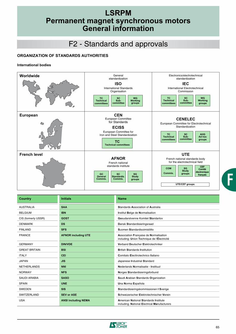
LSRPMPermanent magnet synchronous motors
General information
65
F2 - Standards and approvalsORGANIZATION OF STANDARDS AUTHORITIES
International bodies
Worldwide General standardization
ISOInternational Standards
Organisation
Electronics/electrotechnicalstandardization
IECInternational Electrotechnical
Commission
European CENEuropean Committee
for Standards
ECISSEuropean Committee for
Iron and Steel Standardization
CENELECEuropean Committee for Electrotechnical
Standardization
French levelAFNOR
French nationalstandards institute
UTEFrench national standards body
for the electrotechnical field
Country Initials Name
AUSTRALIA SAA Standards Association of Australia
BELGIUM IBN Institut Belge de Normalisation
CIS (formerly USSR) GOST Gosudarstvenne Komitet Standartov
DENMARK DS Dansk Standardisieringsraad
FINLAND SFS Suomen Standardisoimisliitto
FRANCE AFNOR including UTE Association Française de Normalisationincluding: Union Technique de l'Électricité
GERMANY DIN/VDE Verband Deutscher Elektrotechniker
GREAT BRITAIN BSI British Standards Institution
ITALY CEI Comitato Electtrotechnico Italiano
JAPAN JIS Japanese Industrial Standard
NETHERLANDS NNI Nederlands Normalisatie - Instituut
NORWAY NFS Norges Standardisieringsforbund
SAUDI ARABIA SASO Saudi Arabian Standards Organization
SPAIN UNE Una Norma Española
SWEDEN SIS Standardisieringskommissionen I Sverige
SWITZERLAND SEV or ASE Schweizerischer Elektrotechnischer Verein
USA ANSI including NEMA American National Standards Instituteincluding: National Electrical Manufacturers
TCTechnical
committees
SCSub-
committee
WGWorking groups
TCTechnical
committees
SCSub-
committee
WGWorkinggroups
TCTechnical
committees
SCSub-
committee
AHGAd hocgroups
TCTechnical committees
GCGeneral Commis.
SCStandardiz.
Commis.
SGStudy
groups
COM
Commis.
SGStudy
groups
CEFComité
électroniquefrançais
UTE/CEF groups

66
LSRPMPermanent magnet synchronous motors
General information
F2 - Standards and approvalsList of standards quoted in this document
Reference Date International standards
IEC 60034-1 EN 60034-1 1999 Electrical rotating machines: ratings and operating characteristics
IEC 60034-5 EN 60034-5 2000 Electrical rotating machines: classification of degrees of protection provided by casings of rotating machines
IEC 60034-6 EN 60034-6 1993 Electrical rotating machines (except traction): cooling methods
IEC 60034-7 EN 60034-7 2000 Electrical rotating machines (except traction): symbols for mounting positions and assembly layouts
IEC 60034-8 2001 Electrical rotating machines: terminal markings and direction of rotation
IEC 60034-9 EN 60034-9 1997 Electrical rotating machines: noise limits
IEC 60034-12 EN 60034-12 1999 Starting characteristics for single-speed 3-phase cage induction motors for supply voltages less than or equal to 660 V
IEC 60034-14 EN 60034-14 2004 Electrical rotating machines: mechanical vibrations of certain machines with a frame size above or equal to 56 mm. Measurement, evaluation and limits of vibrational intensity.
IEC 60038 1999 IEC standard voltages
IEC 60072-1 1991 Dimensions and output series for rotating electrical machines: designation of casings between 56 and 400 and flanges between 55 and 1080
IEC 60085 1984 Evaluation and thermal classification of electrical insulation
IEC 60721-2-1 1987 Classification of natural environmental conditions. Temperature and humidity.
IEC 60892 1987 Effects of an imbalance in the voltage system on the characteristics of three-phase squirrel-cage induction motors
IEC 61000-2-10/11 and 2-2
1999 Electromagnetic compatibility (EMC): environment
IEC guide 106 1989 Guidelines on the specification of environmental conditions for the determination of operating characteristics of equipment
ISO 281 2000 Bearings - Basic dynamic loadings and nominal bearing life
ISO 1680 EN 21680 1999 Acoustics - Test code for the measurement of airborne noise emitted by rotating electrical machinery: a method for establishing an expert opinion for free field conditions over a reflective surface
ISO 8821 1999 Mechanical vibration - Balancing. Conventions on shaft keys and related parts
EN 50102 1998 Degree of protection provided by electrical housings against extreme mechanical impacts
Reference Date National standards
FRANCE
NFEN 60034-1 IEC 60034-1 1996 Rules for creating electrical rotating machines
NFC 51-120 1980 Low and medium-power 3-phase induction motors for general applications: fixing positions, connection, internal connections
NFS 31-026 1978 Determination of acoustic power emitted by noise sources: laboratory method in anechoic or semi-anechoic chamber
GERMANY
DIN 40 050 1980 IP Schutzarten; Berührungs - Fredkörper - und Wasserschutz für elektrische Betriebsmittel
DIN 46 294 1985 Rechteckige Klemmenplatten mit 6 Anschlussholzen: Hauptmasse
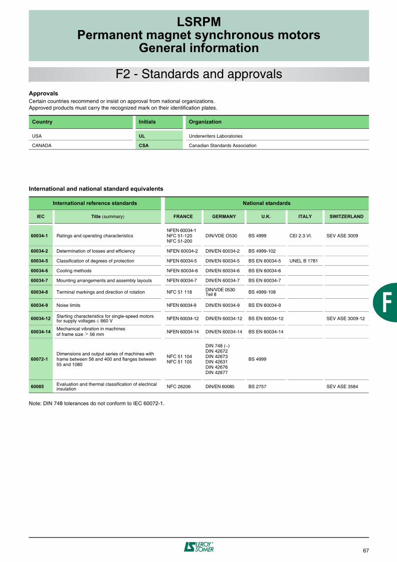
LSRPMPermanent magnet synchronous motors
General information
67
F2 - Standards and approvalsApprovals Certain countries recommend or insist on approval from national organizations.Approved products must carry the recognized mark on their identification plates.
International and national standard equivalents
Note: DIN 748 tolerances do not conform to IEC 60072-1.
Country Initials Organization
USA UL Underwriters Laboratories
CANADA CSA Canadian Standards Association
International reference standards National standards
IEC Title (summary) FRANCE GERMANY U.K. ITALY SWITZERLAND
60034-1 Ratings and operating characteristicsNFEN 60034-1NFC 51-120NFC 51-200
DIN/VDE O530 BS 4999 CEI 2.3.VI. SEV ASE 3009
60034-2 Determination of losses and efficiency NFEN 60034-2 DIN/EN 60034-2 BS 4999-102
60034-5 Classification of degrees of protection NFEN 60034-5 DIN/EN 60034-5 BS EN 60034-5 UNEL B 1781
60034-6 Cooling methods NFEN 60034-6 DIN/EN 60034-6 BS EN 60034-6
60034-7 Mounting arrangements and assembly layouts NFEN 60034-7 DIN/EN 60034-7 BS EN 60034-7
60034-8 Terminal markings and direction of rotation NFC 51 118 DIN/VDE 0530Teil 8 BS 4999-108
60034-9 Noise limits NFEN 60034-9 DIN/EN 60034-9 BS EN 60034-9
60034-12 Starting characteristics for single-speed motors for supply voltages 660 V NFEN 60034-12 DIN/EN 60034-12 BS EN 60034-12 SEV ASE 3009-12
60034-14 Mechanical vibration in machinesof frame size > 56 mm NFEN 60034-14 DIN/EN 60034-14 BS EN 60034-14
60072-1Dimensions and output series of machines with frame between 56 and 400 and flanges between 55 and 1080
NFC 51 104NFC 51 105
DIN 748 (~)DIN 42672DIN 42673DIN 42631DIN 42676DIN 42677
BS 4999
60085 Evaluation and thermal classification of electrical insulation NFC 26206 DIN/EN 60085 BS 2757 SEV ASE 3584

68
LSRPMPermanent magnet synchronous motors
General information
LEROY-SOMER reserves the right to modify the design, technical specifications and dimensions of the products shown in this document.The descriptions cannot in any way be considered contractual.
IP 55Cl. F
The complete motor reference described below will enable you to order the desired equipment.
The selection method consists of following the terms in the designation.
Series designation
Range
Frame sizeIEC 72
Rated outputpower
Power supply
Housing designationand manufacturer
code
Mountingarrangement
IEC 34-7
ProtectionIEC 34-5
4500 LSRPM 225 SR 1 170 kW IM 1001IM B3
400 V IP55
F3 - Designation

Notes

Notes

Notes
I - SPHERE OF APPLICATIONThese General Conditions of Sale (GCS) apply to the sale of allproducts, components, software and provision of services (referred toas "Materials") offered or supplied by the Vendor to the Customer. Theyalso apply to all quotations or offers made by the Vendor, and form anintegral part of any order. "Vendor" means any company controlleddirectly or indirectly by LEROY-SOMER. In addition, the order is alsosubject to the Inter Trades Union General Conditions of Sale for Francefor the F.I.E.E.C. (Federation of Electrical, Electronic andCommunication Industries), latest edition, in that they do not conflictwith the GCS.Acceptance of the Vendor's offers and quotations, or any order, impliesunqualified acceptance of these GCS and excludes any stipulations tothe contrary appearing on all other documents, especially on theCustomer's purchase orders and his General Conditions of Purchase.A dispensation from Paragraph 1 above applies to sales concerningfoundry parts, which are subject to the General Contractual Conditionsof European Foundries, latest edition.Materials and services sold under these GCS may under nocircumstances be intended for applications in the nuclear field,these sales expressly being the subject of special technicalspecifications and contracts which the Vendor reserves the rightto refuse.
II - ORDERSAll orders, including those taken by the Vendor's agents andrepresentatives, by whatever mode of transmission, become valid onlyafter they have been accepted in writing by the Vendor or work on theorder has begun.The Vendor reserves the right to modify the characteristics of hisMaterials without prior notice. However, the Customer may still specifyparticular characteristics required for a contract. In the absence of suchan express specification, the Customer will not be able to refusedelivery of the new modified Material.The Vendor will not accept responsibility for an incorrect choice ofMaterial if this incorrect choice results from incomplete and/orerroneous conditions of use, or these have not been conveyed to theVendor by the Customer.Unless otherwise specified, offers and quotations submitted by theVendor are valid for only thirty days from the date of issue.When the Material has to satisfy standards, particular regulations and/or be inspected by standards or control organisations, the price requestmust be accompanied by a full specification, with which the Vendormust agree. This is mentioned in the quotation or offer. All test andinspection fees are the Customer's responsibility.
III - PRICEPrices are shown exclusive of tax, and may be revised without priorwarning.Prices are either firm for the duration specified on the quotation, orsubject to revision according to a formula accompanying the tenderwhich, according to the regulations, covers a change in the rawmaterials, products, miscellaneous services and salaries.All related costs, such as customs clearance and special inspectionsetc, will be added on.
IV - DELIVERYSales are governed by the INCOTERMS published by the InternationalChamber of Commerce ("I.C.C. INCOTERMS"), latest edition.The Material is dispatched in accordance with the conditions indicatedon the order acknowledgement, sent by the Vendor in response to anyorder for Material.Unless otherwise specified, prices refer to Material made available inthe Vendor's factories, and include standard packaging.Unless otherwise specified, Materials are always transported at thepurchaser's risk. Without exception, it is up to the purchaser to raisewith the transporter, in the legal form and time limits, any claimconcerning the state or the number of packages received and also tosend the Vendor a copy of this declaration. Failure to comply with thisprocedure will relieve the Vendor of all responsibility. In any case, theVendor's responsibility cannot exceed the amount received from hisinsurers.If the arrangements for dispatch are modified by the Customer afteracceptance of the order, the Vendor reserves the right to invoice anyadditional costs arising from such changes.Unless stipulated in the contract or due to a legal obligation to thecontrary, packages cannot be returned.Should the delivery of the Material be delayed, for a reason notattributable to the Vendor, Material stored on his premises will beinsured against risk on behalf of the Customer with a charge for storagecosts at a rate of 1% (one per cent) of the total order sum, per week orpart thereof (irrespective of percentage) as from the availability date asindicated in the contract. After thirty days from this date, the Vendor willbe able, as he wishes, either to dispose of the Material and/or arrangea new delivery date for the said Materials with the Customer, or toinvoice the Customer in full in accordance with the delivery scheduleand amount specified in the contract. In all instances, all depositsreceived remain the property of the Vendor by way of indemnity, withoutprejudice to other actions that the Vendor may institute.
V - DELIVERY DATESThe Vendor is bound only by the delivery dates stated on his orderacknowledgement. These dates are counted from the date of the orderacknowledgement sent by the Vendor, subject to compliance with theprovisions indicated on the order acknowledgement, notably receipt ofthe deposit for the order, notification of the establishment of anirrevocable letter of credit, conforming to all the Vendor's requirements(especially as regards the amount, currency, validity, licence, etc), andacceptance of the various terms of payment as regards setting up anyguarantees which may be required, etc.Late delivery does not automatically entitle the Customer to damagesand interest and/or penalties.Unless otherwise specified, the Vendor reserves the right to makepartial deliveries.Delivery dates are suspended automatically and without legal formality,for any breach of obligations by the Customer.
VI - TESTS - APPROVALMaterials manufactured by the Vendor are inspected and tested prior todispatch from the factory. Customers may attend these tests: theysimply have to state the wish to do so when the order is placed.Specific tests and acceptance tests requested by the Customer, whetherconducted on the Customer's premises, in the Vendor's factories, on site,or by inspection organisations, must be noted on the order and are to bepaid for by the Customer.Prototypes of Materials specially developed or adapted for a Customermust be approved by the Customer before any delivery of productionMaterials in order to make sure they are compatible with the otherconstituent parts of his equipment, and that they are suitable for theCustomer's intended use of them. This approval will also enable theCustomer to make sure that the Materials comply with the technicalspecification. To that end, the Customer and the Vendor will sign twocopies of a Product Approval Form, one copy to be kept by each.In the event of the Customer requiring delivery without havingpreviously approved the Materials, these will then be delivered as theyare and still considered as prototypes; the Customer will then assumesole responsibility for using them or supplying them to his ownCustomers. However, the Vendor may also decide not to deliver theMaterials until they have been previously approved by the Customer.
VII - TERMS OF PAYMENTAll sales are deemed to be undertaken and payable at the Vendor'sregistered office, without exception, whatever the method of payment,the place of conclusion of the contract and delivery.When the Customer is based in France, invoices are payable on receipt
in cash, by banker's draft or by Letter of Exchange, within 30 (thirty)days of the end of the month following the invoice date.Any payment made in advance of the fixed payment date will lead to adiscount of 0.2% (zero point two per cent) per month of the amountconcerned from the invoice.Except as otherwise provided, when the Customer is based outsideFrance, invoices are payable upon issue of the dispatch documents incash, or by irrevocable letter of credit confirmed by a major Frenchbank, all charges paid by the Customer.Payments mean making funds available in the Vendor's bank accountand must be made in the currency of the invoice.Under French Law 2001-420 of 15 May 2001, non-payment of aninvoice by its due date will invoke, after no result from a formal notice,a flat-rate penalty at the date the debt is due, applied to the amountinclusive of tax of the sums due if the invoice is liable to VAT (ValueAdded Tax), and suspension of orders in progress. This penalty is equalto the rate of the European Central Bank + 7%.Should steps have to be taken to recover the said amount, a surchargeof 15% (fifteen per cent) of the sum demanded will be payable, with aminimum of 500 €¤ excl. tax (five hundred euros excluding tax). Any taxdue will be charged to the Customer.Moreover, with the proviso of complying with any legal measures inforce, in the event of non-payment (total or partial) of an invoice or anyamount due, whatever the method of payment envisaged, theCustomer will be liable immediately for the whole of the outstandingamount owed to the Vendor (including his subsidiaries, sister or parentcompanies, whether in France or overseas) for all deliveries orservices, whatever their initial due date.Notwithstanding any particular settlement conditions arranged betweenthe parties, the Vendor reserves the right to demand, as wished, in theevent of deterioration of the Customer's credit, payment incident orcompulsory administration of the Customer:- payment in cash, before the Materials leave the factory, for all ordersin progress,- payment of a deposit for the order,- additional or different payment guarantees.
VIII - COMPENSATION CLAUSEUnless prohibited by law, the Vendor and the Customer expresslyagree between one another the balance of compensation between theirdebts and dues arising from their commercial relationship, even if theconditions defined in law for legal compensation are not all satisfied.In applying this clause, Vendor means any company in the LEROY-SOMER group.
IX - TRANSFER OF RISKS / RESERVATION OF TITLETransfer of risks occurs upon the handing over of the Material,according to the delivery conditions agreed at the time ofordering.Transfer to the Customer of ownership of the Material sold occursupon payment of the whole principal sum, including accessories.In the event of an action to establish title to the delivered Material,deposits paid will remain the property of the Vendor by way ofindemnities.The provision of a document creating an obligation to pay (letterof exchange or similar) does not constitute payment in full.For as long as the price has not been paid in full, the Customer isobliged to inform the Vendor, within twenty-four hours, of theseizure, requisition or confiscation of Materials to the benefit of athird party, and to take all protective measures to inform theVendor and comply with the Vendor's right of property in the eventof intervention by creditors.
X - CONFIDENTIALITYEach party undertakes to maintain confidentiality of information of atechnical, commercial, financial or other nature, received from the otherparty, orally, in writing, or by any other communication method duringnegotiations and/or execution of any order.This confidentiality obligation will apply throughout the period ofexecution of the order and for 5 (five) years after its completion orcancellation, whatever the reason for this.
XI - INDUSTRIAL AND INTELLECTUAL PROPERTYThe results, whether patentable or not, data, studies, information orsoftware obtained by the Vendor during execution of any order are theexclusive property of the Vendor.Apart from instructions for use, servicing and maintenance, reports anddocuments of any type delivered to Customers remain the exclusiveproperty of the Vendor and must be returned to the Vendor on request,even when part of the design fees have been charged to them, and theymay not be communicated to third parties or used without the priorwritten agreement of the Vendor.
XII - CANCELLATION / TERMINATION OF THE SALEThe Vendor reserves the right to cancel or terminate immediately, aswished, as of right and without legal formalities, the sale of his Materialin the event of non-payment of any part of the price by the settlementdate, or in the event of any breach of any of the contractual obligationsto be met by the Customer. Deposits and financial obligations alreadypaid will remain the Vendor's property by way of indemnities, withoutprejudice to his right to claim damages and interest. In the event ofcancellation of the sale, the Material must be returned to the Vendorimmediately, irrespective of its location, at the Customer's expense andrisk, subject to a penalty of 10% (ten per cent) of its value per week late.
XIII - GUARANTEEThe Vendor guarantees the Materials against any operational defect,arising from a material or manufacturing defect, for twelve monthsstarting from the date on which they are made available, unless anyother legal measure effected at a later date might apply, according tothe conditions defined below.The guarantee will only apply insofar as the Materials have been stored,used and serviced in accordance with the Vendor's instructions anddocumentation. It cannot be invoked when the fault results from:- failure to monitor, maintain or store the Materials correctly- normal wear and tear of the Material- intervention on or modification to the Material without theVendor's prior authorisation in writing- abnormal use or use not conforming to the intended purpose ofthe Material- defective installation at the Customer's premises and/or the end user'spremises- non-communication, by the Customer, of the intended purposeor the conditions of use of the Material- failure to use original manufacturer spare parts- in the event of Force Majeure or any event beyond the control of theVendor.In all cases, the guarantee is limited to the replacement or repair ofparts or Materials acknowledged as defective by the Vendor's technicaldepartments. If the repair is assigned to a third party, it should becarried out only after acceptance by the Vendor of the estimate forrepair.No Material should be returned without the Vendor's prior authorisationin writing.Material to be repaired should be sent prepaid, to the address indicatedby the Vendor. If the Material has not been repaired under guarantee,the cost of returning it will be invoiced to the Customer or the endpurchaser.This guarantee applies to the Vendor's Material made accessible andtherefore does not cover the cost of removal and reinstallation of thesaid Material in the unit in which it is integrated.Repair, modification or replacement of parts or Materials during theguarantee period will not have the effect of extending the length of theguarantee.
The provisions of this article constitute the only obligation on the part ofthe Vendor concerning the guarantee for the Materials supplied.
XIV - LIABILITYThe Vendor's liability is strictly limited to the obligations stipulated inthese General Conditions of Sale and those expressly agreed to by theVendor. All penalties and payments specified therein are deemed to beall-inclusive damages and interest, in full discharge and exclusive ofany other sanction or compensation.With the exclusion of serious fault on the Vendor's part andcompensation for bodily injury, the Vendor's liability will be limited, allcauses combined, to a maximum sum of the contractual amountexcluding tax of the supply or service giving rise to the compensation.Under no circumstances will the Vendor be liable to pay for intangibleand/or indirect damages which the Customer might claim; he thereforecannot be held liable in particular for production, operating and otherconsequential losses or more generally any indemnifiable losses otherthan physical or material.The Customer guarantees renunciation of recourse of his insurers orthird parties in a contractual situation with him, against the Vendor or hisinsurers, over and above the limits and for the exclusions laid downabove.
XV - SPARE PARTS AND ACCESSORIESSpare parts and accessories are provided on request insofar as theyare available. Related costs (carriage and any other costs) are alwaysadded to the invoice.The Vendor reserves the right to demand a minimum quantity or invoiceamount per order.
XVI - WASTE MANAGEMENTThe Material covered by the sale does not fall within the scope ofEuropean Directive 2002/96/EC (WEEE) of 27 January 2003, and allresulting laws and decrees of the Member States of the EU, relating tothe composition of electrical and electronic equipment and the disposalof waste originating from this equipment.In accordance with Article L 541-2 of the Environmental Code, it is theresponsibility of the possessor of the waste to dispose of it, or have itdisposed of, at his expense.
XVII - FORCE MAJEUREApart from the Customer's obligation to pay the sums due to the Vendorunder the order, the Customer and the Vendor cannot be heldresponsible for the total or partial non-fulfilment of their contractualobligations if this non-fulfilment results from the occurrence of a forcemajeure situation. The following in particular are considered to be forcemajeure situations: production delays or disruptions resulting wholly orpartially from war (declared or not), an act of terrorism or strikes, riots,accidents, fires, floods, natural disasters, transport delay, shortage ofcomponents or materials, or a governmental decision or act (includingan export ban or revocation of an export licence).If one of the parties is delayed or prevented in the fulfilment of hisobligations because of the present Article for more than 180consecutive days, each party may then cancel, automatically andwithout legal formality, the non-executed part of the order by writtennotification to the other party, without his liability being sought.However, the Customer will be obliged to pay the agreed price relatingto the Materials already delivered at the cancellation date.
XVIII - BAN ON ILLICIT PAYMENTSThe Customer is forbidden any initiative which would expose theVendor, or any related company, to a risk of sanctions by virtue of thelegislation of a State banning illicit payments, in particular bribes andgifts of an obviously unreasonable amount, to the employees of anAdministration or public body, to political parties or their members, tothose standing for an elective post, or to employees of customers orsuppliers.
XIX - CONFORMITY OF SALES TO INTERNATIONAL LEGISLATIONThe Customer agrees that the applicable legislation as regards importand export control, that is to say, that applicable in France, theEuropean Union, the United States of America, in the country where theCustomer is based, if this country does not come under the legislationmentioned previously, and in the countries from which the Materialsmay be delivered, as well as the provisions contained in the licencesand permits relating thereto, of general or dispensatory scope (referredto as "conformity of sales to international regulations"), apply to theacceptance and use by the Customer of the Materials and theirtechnology. Under no circumstances must the Customer use, transfer,dispose of, export or re-export the Materials and/or their technology inviolation of the provisions on conformity of sales to internationalregulations.The Vendor will be under no obligation to deliver the Materials until thelicences or permits necessary under the conformity of sales tointernational regulations have been obtained.If, for any reason whatsoever, the said licences or permits were refusedor withdrawn, or in the event of amendment of the internationalregulations applicable to the conformity of sales which would preventthe Vendor from fulfilling his contractual obligations or which, accordingto the Vendor, would expose his liability or that of his relatedcompanies, by virtue of the international regulations relating to theconformity of sales, the Vendor would then be released from hiscontractual obligations without his liability being invoked.
XX - PARTIAL INVALIDITYAny clause and/or provision of these General Conditions deemed and/or which has become null and void does not render the contract null andvoid, only the actual clause and/or provision concerned.
XXI - DISPUTESTHIS CONTRACT IS SUBJECT TO FRENCH LAW.IN THE ABSENCE OF AMICABLE AGREEMENT BETWEEN THEPARTIES, AND NOTWITHSTANDING ANY CLAUSE TO THECONTRARY, ANY DISPUTE RELATING TO THE INTERPRETATIONAND/OR EXECUTION OF AN ORDER MUST BE RESOLVED BYTHE COMPETENT COURTS OF ANGOULEME (FRANCE), EVEN INTHE CASE OF INTRODUCTION OF THIRD PARTIES OR MULTIPLEDEFENDANTS. HOWEVER, THE VENDOR RESERVES THEEXCLUSIVE RIGHT TO BRING ANY DISPUTE INVOLVING THECUSTOMER BEFORE THE COURTS OF THE LOCATION OF THEVENDOR'S REGISTERED OFFICE OR THOSE WITHIN WHOSEJURISDICTION THE LOCATION OF THE CUSTOMER'SREGISTERED OFFICE FALLS.
398 EN - 12.2005 / kGENERAL CONDITIONS OF SALELEROY-SOMER


MOTEURS LEROY-SOMER 16015 ANGOULÊME CEDEX - FRANCE
338 567 258 RCS ANGOULÊME S.A. au capital de 62 779 000 €
www.leroy-somer.com