00391901
TRANSCRIPT

8/2/2019 00391901
http://slidepdf.com/reader/full/00391901 1/9
339EE E Transactions on Energy Conversion, Vol. 10, No. 2, June 1995
Neural Netw ork-Based Self-organ izing Fuzzy Controller for T ransient Stabilityof M ultimachine Power Systems
Hong-Chan Chang, Mem ber, IEEE, Mang-Hui Wang , Student Member, IEEE
Department of Electrical Engineering, National Taiwan Instituteof Technology Taipei, Taiwan, ROC
Abstract- An efficient self-organizing neural fuzzy controller
(SONFC) is designed to improve the transient stability of
multimachine power systems. First, an artificial neural network
(ANN)-based model is introduced for fuzzy logic control. The
characteristic rules and their membership functions of fuzzy
systems are represented as the processing nodes in the ANN
model. With the excellent learning capability inherent in the
ANN, the traditional heuristic fuzzy control rules and
inputloutput fuzzy membership functions can be optimally
tuned from training examples by the backpropagation learning
algorithm. Considerable rule-matching times of the inference
engine in the traditional fuzzy system can be saved. To illustrate
the performance and usefulness of the SONFC, comparative
studies with a bang-bang controller are performed on the 34-generator Taipower system with rather encouraging results.
Keywords: Self-organizing neural fuzzy controller, transient
stability control, bang-bang controller.
1 . INTRODUCTION
Transient stability is one of the most important factorsthat should be studied in power system planning, operation,and extension. It is mainly concerned with a system's abilityto remain in synchronization following a sudden and majordisturbance such as a generator trip or line switching due tofaults, or abrupt changes in load or generation powers.Modem power systems have placed increased emphasis onthe development of effective control schemes to enhancetransient stability. In the past, numerous investigations havebeen conducted to improve the transient stability of powersystems, ranging from theoretical studies to advanced controldevices [l-61. Means for transient stability control are
usually of the nonlinear discontinuous type, such asgeneration dropping [ 1, dynamic braking [2-41, loadshedding [5], etc. The conventional control approach mostoften requires a precise mathematical model of the controlledsystems. However, for power systems in practice, since thereexist parameter uncertainty problems in the plant modelingand large variations in the environmental conditions, the
94 SM 372-3 ECby the IEEE Energy Development and Power GenerationCommittee of th e IEEE Power Engineering Society forDre sen ta tio n a t t he IEEE/PES 1994 Summer Meeting,
A paper recommended and approved
conventional controllers often perform satisfactorily over arather limited range of operation.
Recently, artificial neural networks and fuzzy systemshave been successfully applied to various control fields withrather promising results [7-101. The salient feature of thesetechniques that distinguish them from the traditional controlapproaches is that they provide a model-free description ofthe control systems. A fuzzy logic controller is a special typeof knowledge-based controller, and it operates in a linguistic,rule-based manner. Its performance depends strongly on thecontrol rules developed. Generally, designinga fuzzy controlsystem always requires much trial-and-error effort indetermining the fuzzy rules and the associated membershipfunctions, thus making the design a time-consuming task. Onthe other hand, artificial neural networks that mimic the
function of the brain in a simplified manner can beconsidered another candidate for intelligent control systems.The neural systems use a large number of numeric input-output samples to produce the mapping rules throughlearning. Learning from examples and dynamic adaptationare two major features of neural networks. However, themapping rules in the neural network are not visible and aredifficult to understand.
In this paper, a self-organizing neural fuzzy controller(SONFC) is designed to enhance the transient stability ofpower systems. By the term self-organizing controller [ l l-131, it is meant that the controller can create fuzzy controlrules to control a plant by learning. First, the neural network-based model for fuzzy logic control [lo] is introduced. Thismodel integrates the ideas of the fuzzy logic controller andneural network structure into an intelligent control system. In
this AN N structure, the input and output nodes represent theinput speed/acceleration states, and output control signal,respectively, and the nodes in the hidden layers function asmembership functions and fuzzy rules. Initially, we set upthe controller with a set of coarse fuzzy control rules that arebased on a simple engineering knowledge concerning thecontrolled machine. Then, the fuzzy rules and inputloutputmembership functions of the controller can be optimallytuned or adapted by the backpropagation learning algorithmaccording to the control credit that is evaluated by aperformance index table. With the evolving symbiosis of
AN N and fuzzy logic theory, the presented controller isshown to be robust, adaptive and capable of learning. Inaddition, it also has the advantages of efficient hardwareusage, easy generalization, and fault tolerance [10,14]. To
san Francisco, CA , July 24 - 28, 1 9 9 4 . w u s & i p t demonstrate the effectiveness of the proposed controller,submitted December 30, 1993; made available for comparative studies with a bang-bang controller [31 arepri nti ng June 20, 1994. conducted on the 34-generator Taipower system.
0885-8969/95/$04.00 0 1994 IEEE

8/2/2019 00391901
http://slidepdf.com/reader/full/00391901 2/9
340
2.PROBLEM ORMULATION
2.1 Pow er System Model
The system of equations that govem the power systemdynamics of transient stability control are fiist described. Ann-machine power system model including the effects of fieldflux decay, damper windings, the automatic voltage regulator(AVR), and the exciter conceming a center of inertia (COI)rotating reference frame is given below [15]:
0. = (3. (1 )
(2)
(3)
(4)
( 5 )
(6)
l l
M . h . = P . - p . - % p COI-Vi
TioiE& = -E;i + ( x d i - i i ) l d j + Efdi
T;,iEii = -E& - (X ’ -X’ . ) I .
Ta1,Vn = -V , + KaiVej
nu e’ MT1
41 41 41
TeiEfdi = -(Sei + Kei ) E f d + Vrli
T f i Vfi = - V f i + ( K f i / Te j ) [ V , l i - (Se i + K e i ) E f d ] (1
subscript “i “: elating to the i-th generator,
E;, E; :d- and q-axis stator emfs,
Efd : field applied voltage,
Zd Z :d- and q-axis components of armature current,
K , : regulator gain,Ke :exciter constant related to self-excited field,Kf : regulator stabilizing circuit gain,
M : nertia constant,Pm :mechanical power input,
Pe : eal power output,
P c 0 1 :CO1accelerating power,
Se : xciter saturation function,
T i o ,T i , :open circuit d- and q-axis time constants,
T, : regulator amplifier time constant,
Te :exciter time constant,T f : regulator stabilizing.circuit time constant,V , : regulator output voltage,
Vf: utput voltage of regulator stabilizing circuit,X X :d- and q-axis synchronous reactances,d q
X i , X i :d- and q-axis transient reactances,
0i : rotor angle of generator i with respect to the COI,
W i : otor speed of generator i with respect to the COI,
o, center of system speed.
where
4
In (2), the term Ui represents additive real power control for
the i-th generator, which is determined by the controllerdepending on the state of the generator.
2.2 Transient Stability Control
Following a major disturbance in a power system, thesystem may lose synchronization if proper control action is
not taken. The rotor trajectories of the generators may fallapart into different coherent groups during the transientperiod, and the unstable generators tend to separate from therest of the system. Therefore, the ultimate goal of transientstability control is to quickly transfer the unstable generatorfrom its initial state to the post-fault equilibrium state underadmissible control limits. The rotor speed of each generatormust eventually follow the overall system to maintainstability. In other words, for a transient stable system, thetarget steady state of each generator after a disturbance mustbe prescribed by:
for i=1,2,..., nc S j ( t f )= 0
where W i ( t f ) and & ( t f ) denote the final states of rotor
speed and acceleration of generator i, respectively. In aphysical system, the control power U i ( t ) is usuallyconstrained by:
In practical applications, control power U i ( t ) can beimplemented by a braking resistor [2,4] to consume transientsurplus power, a fast valve to shed the mechanical power, orit may be implemented by a superconducting magneticenergy storage (SMES) unit 1161.
3. THE SELF-ORGANIZING NEURAL FUZZY CONTROLLER
The major difficulty in the design of a fuzzy controllerarises from the determination of fuzzy rules and inpudoutputmembership functions. Most approaches are based onstudying a human-operated system or existing controller, andthe membership functions and/or fuzzy rules are thenmodified when the design fails in the test. Therefore, it
always requires a lot of trial-and error effort, thus making thedesign a time-consuming task. The recent direction of
research is to design self-organizing fuzzy logic systems thathave capability to create the control strategy by learning[12,13].Basically, we will follow the ideas of the traditionalself-organizing fuzzy logic system with significantmodification. The structure of the proposed SONFC is acombination of both the neural network and fuzzy logictechniques. The fuzzy method proves a structural controlframework to express the input-output relationship of theneural network, and the neural network can embed the salientfeatures of computation power and learning capability intothe fuzzy controller.
3. 1 Overall Structure
The schematic structure of the proposed SONFC systemis shown in Fig. 1 . It consists of: (i) a performance index (PI)
table as an instructor for learning the control strategy, (ii) aneural fuzzy controller (NFC) to control the plant, (iii) threescaling factors GS , GA, and G U to adjust the inpudoutputvalues of the controller into proper ranges, which are set at 1,

8/2/2019 00391901
http://slidepdf.com/reader/full/00391901 3/9
341
0.01, and 1, respectively, and (iv) a limiter to constrain thecontrol action within admissible limits. Typical inputvariables for transient stability control, for example, are therotor angle, angular speed, angular acceleration, etc. Since noprior information regarding the rotor angle at postfaultequilibrium is known, the shaft speed and acceleration of thegenerator at each sampled time are employed as the inputvariables of the proposed controller.
The implementation of the proposed control systemmainly comprises two phases: the learning phase andoperation phase. In the learning phase, the purpose is to tunethe parameters of the NFC to achieve good controlperformance. The performance of the controller in eachlearning step is evaluated by a performance index (PI) table,from which a credit is assigned according to the deviation ofthe control response from the desired response. Then themembership functions and fuzzy rules of the fuzzy controllercould be adapted on-line by the credit value using asupervised learning mechanism. When the performance ofthe NFC is reduced to a preset value, the learning processterminates. In the operation phase, the trained NFC isdirectly used to control the machine.
FQ.1.Schematicstructureof theproposedcontrol system.
3.2 Topology of the neuralfuzzy controller
The proposed NFC is a multilayer neural network-based
fuzzy controller. Its topology is shown in Fig. 2. The systemhas a total of five layers. Since two input variables and oneoutput variable are employed in the present work, there aretwo nodes in layer 1and one node in layer 5. Nodes in layer1 are input nodes that directly transmit input signals to thenext layer. Layer 5 is the output layer. Nodes in layers 2 and4 re term nodes that act as membership functions to expressthe inputloutput fuzzy linguistic variables. A bell-shapedfunction, as shown in Fig. 3, is adopted to represent themembership function, in which the mean value m and thevariance o will be adapted through the learning process. Thefuzzy sets defined for the inputloutput variables are positivebig (PB), positive medium (PM), positive small (PS), zero(ZE), negative small (NS), negative medium (NM), andnegative big (NB), which are numbered in descending orderin the term nodes. Hence, 14nodes and 7 nodes are includedin layers 2 and 4, espectively, to indicate the input/outputlinguistic variables. Each node of layer 3 is a rule node thatrepresents one fuzzy control rule. In total, there are 49 nodesin layer 3 to form a fuzzy rule base for two linguistic input
A 1o. of nodes
-T-Layer 5(outputnode)
7
49
14
2
5; 6;
Fig. 2.Topoio~y f the neural funycontroller
m X
Flg. 3. Curve of bell shaped function.
variables. Layer 3 links and layer 4 inks define thepreconditions and the consequences of the rule nodes,respectively. For each rule node, there are two fixed linksfrom the input term nodes. Layer 4 inks encircled in dottedline will be adjusted in response to varying control situations.By contrast, the links of layers 2 and 5 remain fixed betweenthe inputloutput nodes and their corresponding term nodes.In short, the proposed SONFC can adjust the fuzzy controlrules and their membership functions by modifying layer 4links and the parameters that represent the bell-shapedmembership functions for each node in layers 2 and4. n thefollowing, special emphasis is placed on how to adapt theselinks and parameters through learning. As a convenience innotation, the following symbols are used to describe the
functions of the nodes in each of the five layers:
net:: the net input value to the i-th node in layer L,
0: : the output value of the i-th node in layer L,
m:, 0;: he mean and variance of the bell-shapedactivation function of the i-th node in layerL,
WG the link that connects the output of the j-th node in
layer 3 with the input to the i-th node in layer 4.
b y e r 1:
signals to the next layer. That isThe nodes of this layer just directly transmit input
b v e r 2:
The nodes of this layer act as membership functions toexpress the terms of input linguistic variables. For a bell-
.
8/2/2019 00391901
http://slidepdf.com/reader/full/00391901 4/9
342
shaped function, they are:
for i=1, 2,...,7
for i=8,9, ..,14net: = {z
, t2-m2-(I)= e ( f or i= I, 2, ...,14 (12)
Note that layer 2 links are all set to unity.
Layer 3;
The links in this layer are used to perform preconditionmatching of fuzzy rules. Thus, each node has two inputvalues from layer 2. The correlation-minimum inferenceprocedure [lo] is utilized here to determine the firingstrengths of each rule. The output of nodes in this layer isdetermined by the fuzzy AND operation. Hence, thefunctions of the layer are given below:
net; = min(O;, Of), i = 7(7- j ) + (k- 7)
oi =net; fori=1,2, ...,49
forj=I,2, ..,7; =8,9, ..,143
The link weights in this layer are also set to unity.
Laver 4;Each node of this layer performs the fuzzy OR operation
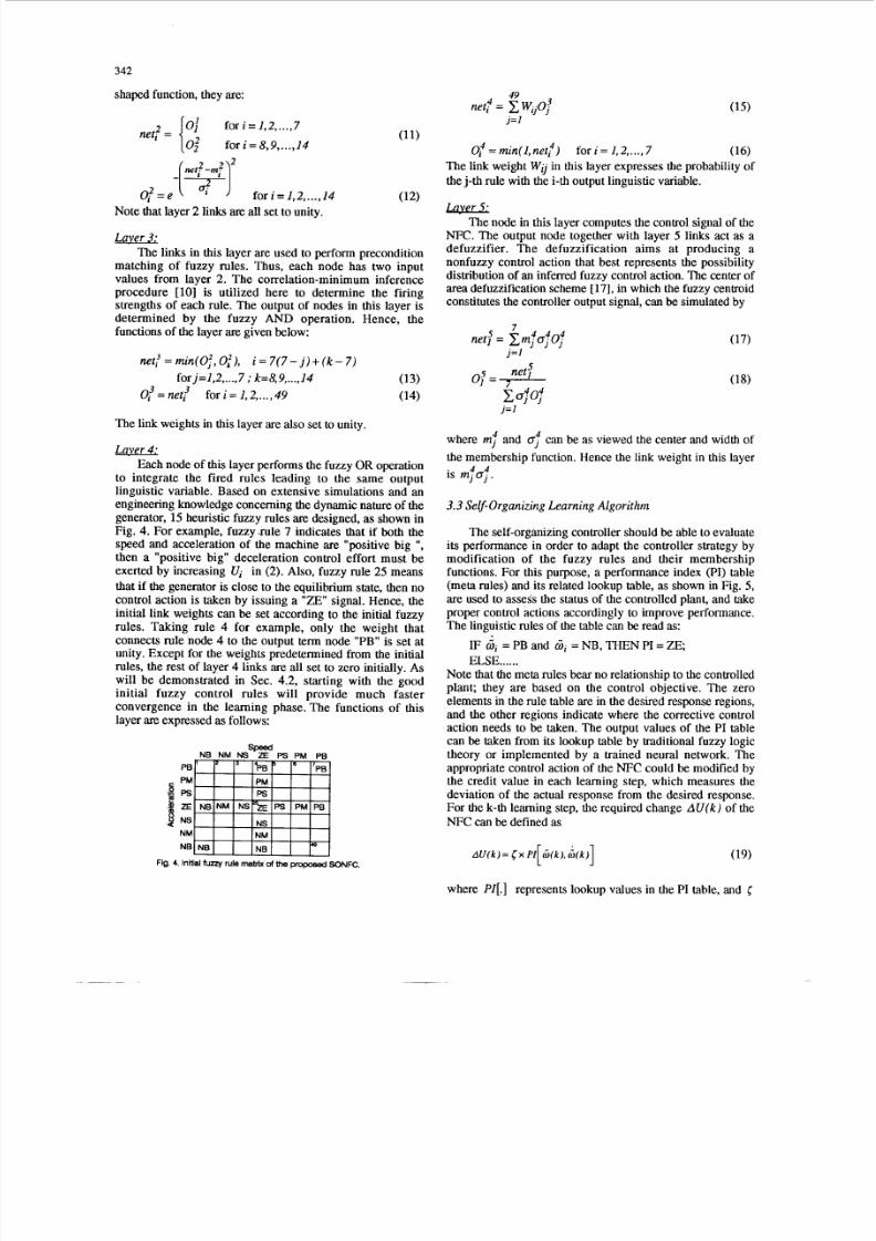
to integrate the fired rules leading to the same outputlinguistic variable. Based on extensive simulations and anengineering knowledge concerning the dynamic nature of thegenerator, 15 heuristic fuzzy rules are designed,as shown inFig. 4. For example, fuzzy.rule 7 indicates that if both thespeed and acceleration of the machine are "positive big 'I,
then a "positive big" deceleration control effort must beexerted by increasing Vi in (2). Also, fuzzy rule 25 means
that if the generator is close to the equilibrium state, then nocontrol action is taken by issuing a "ZE" signal. Hence, theinitial link weights can be set according to the initial fuzzy
rules. Taking rule 4 for example, only the weight thatconnects rule node 4 to the output term node "PB" is set atunity. Except for the weights predetermined from the initialrules, the rest of layer 4 links are all set to zero initially. Aswill be demonstrated in Sec. 4.2, starting with the goodinitial fuzzy control rules will provide much fasterconvergence in the learning phase. The functions of thislayer are expressed as follows:
speedNB NM NS ZE PS PM PB
PB
NMNB
49
j= I
net: = cwij0j'
0: = min(1, net: ) for i = 1,2,. 7 (16)
The link weight W ;j in this layer expresses the probability of
the j-th rule with the i-th output linguistic variable.
L.WL2The node in this layer computes the control signal of the
NFC. The output node together with layer 5 links act as adefuzzifier. The defuzzification aims at producing anonfuzzy control action that best represents the possibilitydistribution of an inferred fuzzy control action. The center of
area defuzzification scheme [17], in which the fuzzy centroidconstitutes the controller output signal, can be simulated by
net: = Emj 4 4jojj = l
net.'0: =
a;0;j =I
where m and a; can be as viewed the center and width of
the membership function. Hence the link weight in this layer4 4is m j o j .
3.3Self-organizing Learning Algorithm
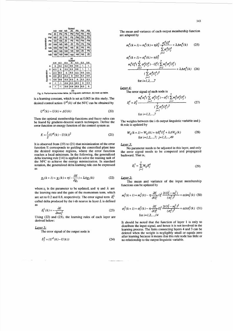
The self-organizing controller should be able to evaluateits performance in order to adapt the controller strategy bymodification of the fuzzy rules and their membershipfunctions. For this purpose, a performance index (PI) table(meta rules) and its related lookup table, as shown in Fig. 5,are used to assess the status of the controlled plant, and takeproper control actions accordingly to improve performance.
The linguistic rules of the table can be read as:IF hi = PB and ii NB , THEN PI = Z E
ELSE......Note that the meta rules bear no relationship to the controlledplant; they are based on the control objective. The zeroelements in the rule table are in the desired response regions,and the other regions indicate where the corrective controlaction needs to be taken. The output values of the PI tablecan be taken from its lookup table by traditional fuzzy logictheory or implemented by a trained neural network. Theappropriate control action of the NFC could be modified bythe credit value in each learning step, which measures thedeviation of the actual response from the desired response.For the k-th learning step, the required change AU( k ) of the
NFC can be defined as
Fig. 4. Initial fuzzy rule maMx of theproposed SONFC.
where PI[.] epresents lookup values in the PI table, and <
8/2/2019 00391901
http://slidepdf.com/reader/full/00391901 5/9
343
(4
-0.6 -0.3 -0.3 s y 0 . 3 0 .3 .0.6 I
(b)Fig. 5. Performance index table, (a) linguistic definition, (b) look uptable
is a learning constant, which is set at 0.005 in this study. The
desired control action U d ( k ) of the NFC canbeobtained by
U d ( k )= U ( k )+ A U ( k ) (20)
Then the optimal membership functions and fuzzy rules canbe found by gradient-descent search techniques. Define theerror function or energy function of the control system as
The mean and variance of each output membership functionare adapted by
j = l
for i=1,2,...,7
mThe error signal of each node is
j = l
for i=1,2,...,7
The weights between the i-th output linguistic variable and j-th rule is updated by
I
2E = - (U d ( k )-U ( k ) ) 2
Wi k+ ) = Wij( k ) ~ 6 f O ; A A W j j (k) (28)(21)
for i=1,2,...,7; j = I , 2,...,49
It is observed from (19) to (21) that minimization of the errorfunction E corresponds to guiding the controlled plant into
the desired response regions, where the error functionreaches a local minimum. In the following, the generalizeddelta learning rule [141 is applied to solve the training task of
notation, the generalized delta learning rule can be expressed
as j = l
Laver 3;No parameter needs to be adjusted in this layer, and only
the error signal needs to be computed and propagatedbackward. That is,
the NFC to achieve the energy minimization. In standard7
6 = CW-64 (29)J
(22) JaE
aXi
wherexi is the parameter to be updated, and q and A are
the learning rate and the gain of the momentumterm,which
are set to 0.2 and 0.8, respectively. The error signal term 6
Xi(k +1)= X i ( k )+ q(--) + AAXi(k)The mean and variance of the input membership
functionscanbe updated by
m,?(k+ I)= m,?(k) - q- + aAm.,2(k) (30)I E ?2(0f -m f )
30; ' (d)2called delta produced by the i-th neuron in layer L is definedas
aE 2 2(of-q2)2 + d o , ? ( k ) (31)Si ( k ) = - - dE (23) o f ( k + l ) = d ( k ) - V T O io, (0: 3
anet:for i=1,2,...,14
Using (22) and (23), the learning rules of each layer x ederived below:
It should be noted that the function of layer 1 is only to
distribute the input signal, and hence it is not involved in thelearning process. The links connecting layers 4 and 3 can bedeleted when the weight is negligibly small or equals zeroafter learning because it means that this rule node has little or
LwckThe error signal of the output node is
6 = ( U d ( k ) - U ( k ) ) (24) no relationship to the output linguistic variable.
8/2/2019 00391901
http://slidepdf.com/reader/full/00391901 6/9
344
4. SIMULATION RESULTS
4.1 Test Condition
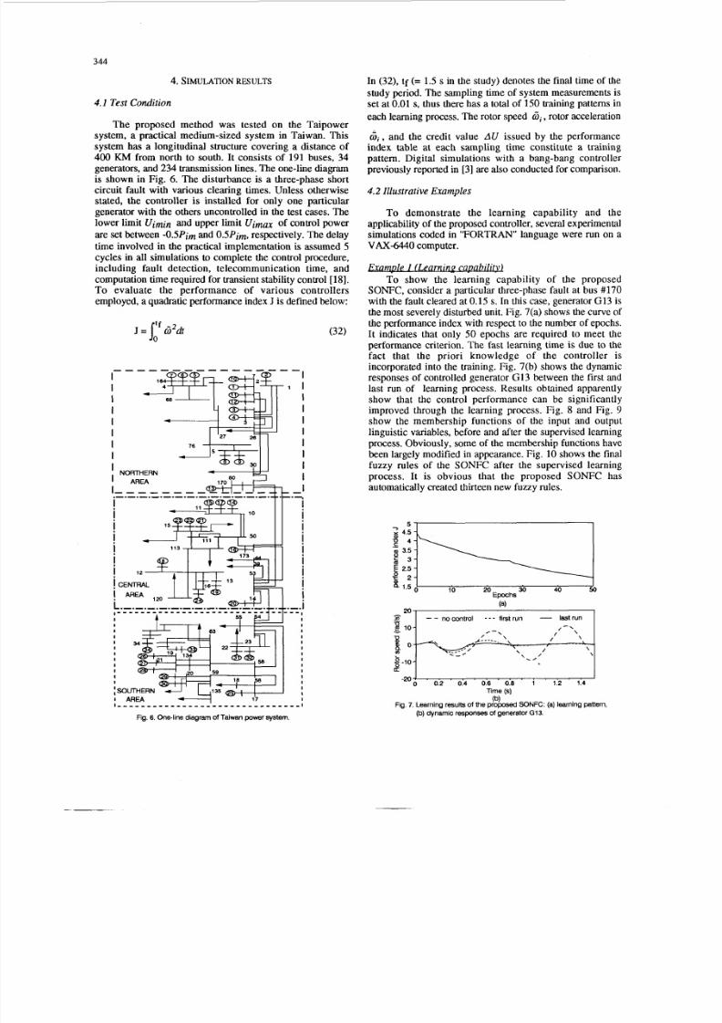
The proposed method was tested on the Taipowersystem, a practical medium-sized system in Taiwan. Thissystem has a longitudinal structure covering a distance of400 KM from north to south. It consists of 191 buses, 34
generators, and 2 34 transmission lines. The one-line diagramis shown in Fig. 6. The disturbance is a three-phase shortcircuit fault with various clearing times. Unless otherwisestated, the controller is installed for only one particulargenerator with the others uncontrolled in the test cases. Thelower limit Uimin and upper limit U i m m of control power
are set between -0.5Pim and OSPim, respectively. The delaytime involved in the practical implementation is assumed 5
cycles in all simulations to complete the control procedure,including fault detection, telecommunication time, andcomputation time required for transient stability control [NI.To evaluate the performance of various controllersemployed, a quadratic performance index J is defined below:
--IIIIII
J =6' 'dt
I 78 1 1
- 1II
I
II
IIIII
In (32), tf (= 1.5 s in the study) denotes the final time of thestudy period. The sampling time of system measurements isset at 0.01 s, thus there has a total of 150 training pattems in
each learning process. The rotor speed Gi, otor acceleration
G i , and the credit value AU issued by the performanceindex table at each sampling time constitute a trainingpattern. Digital simulations with a bang-bang controller
previously reported in [3] are also conducted for comparison.
4.2 Illustrative Examples
To demonstrate the learning capability and theapplicability of the proposed controller, several experimentalsimulations coded in "FORTRAN" language were run on aVAX-6440 omputer.
. .mple I ( k a r n i w
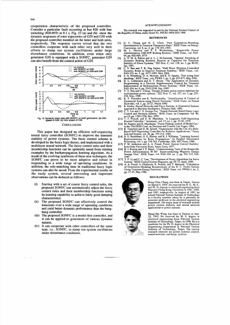
To show the learning capability of the proposedSONFC, consider a particular three-phase fault at bus #170with the fault cleared at 0.15 s. In this case, generator G1 3 isthe most severely disturbed unit. Fig. 7(a) shows the curve ofthe performance index with respect to the number of epochs.It indicates that only 5 0 epochs are required to meet the
performance criterion. The fast learning time is due to thefact that the priori knowledge of the controller is
incorporated into the training. Fig. 7(b) shows the dynamicresponses of controlled generator G I 3 between the first andlast run of learning process. Results obtained apparentlyshow that the control performance can be significantlyimproved through the learning process. Fig. 8 and Fig. 9 show the membership functions of the input and outputlinguistic variables, before and after the supervised learningprocess. Obviously, some of the membership functions havebeen largely modified in appearance. Fig. 10 shows the finalfuzzy rules of the SONFC after the supervised learningprocess. It is obvious that the proposed SONFC hasautomatically created thirteen new fuzzy rules.
57E 4.5
e 4
a 3.5
5 3
$ 2
2.5
8 .5---:-_10 20 Epochs
nocontrol - - - first run - astrun IU
0 0.2 0.4 0.6 0.8 1 1.2 1.4- 2 0 4 . . , . . . " " _ . '
Time (s)
Fig. 7 . Learning resultsof the proposedSONFC: (a) learning pattern,(b)
(b)dynamic responses of generator G13.

8/2/2019 00391901
http://slidepdf.com/reader/full/00391901 7/9
345
1 -
0.5
1.5NB NM NS ZE PS PM PB I
-
150% loading
100% loading50% loading
L9 -2
Time (s)
fault cleared at 0.15 sfault cleared at 0.10 s
L O
0 0.2 0.4 0.6 0.8 1.2 1.4
Time (s)
(b)Fig. 11. Dynamic res nses of generator GI3 with (a) different loading
conditions, (cdif ferent fault clearning times.
1 -
0.5
NB NM NS ZE PS PM PB.3
Acceleration1.5
NB NMNS ZE PSPM PB
"- 1 NB NM NS ZE PS PM PB I
"" 1 NB NM NS ZE PS PM PB I
I NB NMNS ZEPSPM PB I
Fig. 9. learned membership functionsof the proposed SONFC
5
2
Pe-m
Fig. 10
PM
Ps
ZE
NS
NM
NB
. Leared fuzzy rule matrix of the proposed SONFC
ExamDle 2 (Robustness re&
To test the robustness of the trained SONFCconcerninga wide range of operating conditions, consider a three-phasefault at bus #170. The dynamic responses of generator G13are shown in Fig. 11, where Fig. ll (a ) depicts the dynamicresponses with the loading varied from 50%to 150% and thefault cleared at 0.1 s, and Fig. l l( b) with the fault cleared at0.1, 0.15, and 0.2 s and 100% loading. Noticeably, althoughthe SONFC was trained from past control trends, it is stillcapable of yielding satisfactory transient responses for alarge alternation concerning loading and operationconditions. The rotor trajectories can be quickly recovered to
the steady state in less than 0.6 s.
le 3 ( Pe jo rm ac e C o m v a r dTo compare the control performance of the proposed
SONFC and the bang-bang controller [3], comprehensive
test including different fault locations and disturbances in theTaipower system has been performed. The controlledgenerators involved in the simulation studies are of differentdynamic characteristics. The partial results of the test areshown in Table I. Note that the proposed SONFC can
consistently provide better dynamic performance than thebang-bang controller. For example, consider a three-phasefault occurring at bus #2 with the fault cleared at 0.1s. Thesample responses of generator G2 with various controllersare shown in Fig. 12, where curve "NC" is with no control,
TABLE I
COMPARISON OF PERFORMANCE INDEX WITH VARIOUSCONTROLLERS
1.41.2-
E 0.:
9 0.60.4
: .2
s or p -0.2
-0.4
Fig.
NCBBC
- ONFC
_ _
1 . , , : . , , , , ,- . . ' . , I/-'''-'I0 0.2 0.4 0.6 0.8 1 1.2 1.4
12.Cynamic responses of generator G2 with various controllers.Time (s)
curve "BBC" is witli the bang-bang controller, and curve"SONFC" is with the proposed self-organizing neural fuzzycontroller. With no control action, the system is unstable as
indicated in curve "NC". In comparison with the bang-bangcontroller, the proposed SONFC can yield a better dynamicresponse with less overshoot and shorter settling time.
EllamDk 4 (Cooperation characteristic)The purpose of this example is to illustrate the
8/2/2019 00391901
http://slidepdf.com/reader/full/00391901 8/9
346
4 -9 3 -v
1-1!
cooperation characteristic of the proposed controller.Consider a particular fault occurring at bus #20 with lineswitching (#20-#59) at 0.1 s. Fig. 13 (a) and (b) show thedynamic responses of rotor trajectories of G29 and G30 withthe proposed controller installed on the latter and both units,respectively. The response curves reveal that the twocontrollers cooperate with each other very well in theirefforts to damp out system oscillations under large
disturbance conditions. In addition, even when onlygenerator G30 is equipped with a SONFC, generator G29can also benefit from the control action of G29.
nocontrolwith SONFConG30
- ithSONFConG29and G30
- -
, - -_-----,
!A\\, - - - _
0 ' 012 0.4 0.6 0.8 1 1.2 1.4L b j
Time (s)
'.-.'0 ' 0:2 0.4 0.6 0.8 1 1.2 1.4E :; i
Time (s)(b)
Fig. 13.Dynamic r e s p 0 - w ~ ith SONFC on both generators: (a) rotorspeed of G29. b) rotor speed ofG30.
CONCLUSIONS
This paper has designed an efficient self-organizingneural fuzzy controller (SONFC) to improve the transientstability of power systems. The basic control scheme isdeveloped by the fuzzy logic theory, and implemented with amultilayer neural network. The fuzzy control rules and theirmembership functions can be optimally tuned from trainingexamples by the backpropagation learning algorithm. As aresult of the evolving symbiosis of these new techniques, theSONFC can prove to be more adaptive and robust in
responding to a wide range of operating conditions. Inaddition, the rule-matching time in traditional fuzzy logicsystems can also be saved. From the experimental results onthe study system, several interesting and importantobservations can be deduced as follows:
(i) Starting with a set of coarse fuzzy control rules, theproposed SONFC can automatically adjust the fuzzycontrol rules and their membership functions usingits learning capability to achieve fairly good dampingcharacteristics.
(ii) The proposed SONFC can effectively control thetransients over a wide range of operating conditionsand yield better dynamic performance than the bang-bang controller.
(iii) The proposed SONFC is a model-free controller, and
it can be applied to generators of various dynamicnatures.(iv) It can cooperate with other controllers of the same
type, i.e., SONFC, to damp out system oscillationsunder disturbance conditions.
ACKNOWLEDGMENT
The research was supported in pari by the N ational Science Council ofthe Republic of China, under Grant No. NSC8 1-040 4E011 -009.
REFERENCES
[l ] H. C. Chang and H. C. Chen, "Fas t Genera t ion-SheddingDetermination in Transient Emergency State," IEEE Trans. on EnergyConversion, vol. 8, no. 2, pp. 178-183, 1993.
[2] M . L. She l ton and P . F . Winke lman, "Bonnevi l le PowerAdministration 1400-MW Brak ine Resistor." IEEE Trans.. vol. PAS-
94, pp. 602-609, 1975.A. H. M. A. Rahim and A. L. J. AI-Sammak, "Optimal Switch ing ofDynamic Braking Resistor, Reactor or Capacitor for TransientStability of Power Systems," IE E Proc.C, vol. 138, no. 1, pp. 89-93,Jan. 1991.
-[3]
[4]
[5]
[6]
C-S. Rao an d T. K. Nag Sarkar, "Half Wave Thyristor ControlledDynamic Brake t o Improve T ransient Stabili ty," IEEE Trans., vol.PAS-103, no. 5, pp. 1077-1083, May 1984.S . A. Nirenberg, D. A. Mciunis, and K. D. Sparks, Fast acting loadshedding," IEEE Trans., vol. PWRS-7, no. 2, pp. 873-877, May 1992.D.L. Lubkemen and G. T. Heydt, "The Application of DynamicProgramming in a Discrete Supplementary Control for TransientEnhancement of M ultimachine Power Systems," IEEE Trans. vol.PAS-104, no. 9, pp. 2342-2348, Sep. 1985.Y. Y. su and C. Cheng, "Design of fuzzy power system stabilizer formultimachine power systems," IEE Proc.C, vol. 137, no. 3, pp. 233-238, May, 1990.K. S. Narendra and K. Parthasarathy, "Identification & Control ofDynarmcal System using Neural Networks," IEEE Trans. on NeuralNetworks, vol. 1, pp. 24-27, March 1990.
[9] B. Kosko, Neural Networks andF u u y Systems: A Dynamical System
Approach to Machine Intelligence. Prentice-Hall, 1992.[ lo] C. T. Lin and C. S. George Lee, "Neural-Network Based Fuzzy LogicControl and Decision System," IEEE Trans. on Computers, vol. 40,no.12, pp. 1320-1336, Dec. 1991.
[ l l] T. J. Procyk, and E. H. Mamdani, "A Linguistic Self-organizingProcess Controller," Automatic, vol. 15, no. 1, pp. 15-30, 1979.
[12] M. Sugen o and K. Murakami, "Fuzzy Parking control of Model Car,"in the 13rd IEEE Conf. on Decision and Control, Las Vegas, 1984.
[13] R. Tauscheit and E. M. Scharf, "Experiments with the Use of a Rule-Based Self-org anizing Controller for Robotics A pplications," FuzzySets and System, vol. 26, pp. 195-214, 1988.
[14] D. E. Rumelhar t, G. E. Hinton, and R. J. Williams, "Learning InternalRepresentations by Error Propagation," In Parallel DistributedProcessing. vol. 1 , pp. 318-362, Cambridge, MA. MIT Press, 1986.
[15] P. M. Anderson and A. A. Fouad, Power System Control Stability.Iowa State University Press, Ames, Iowa, 1977.
[16] H. J. Boenig and 1. F. Haner, "Commissioning Tests of the BonnevillePower Administration 30 MJ Superconducting Magnetic EnergyStorage Unit," IEEE Trans. vol. PAS-104, no. 2, pp. 301-312, Feb.1985.
[17] Y. F. Li and C. C. Lau, "Development of Fuzzy A lgorithms for ServoSystem," IE EE Control System M agazine, pp. 65-72, April, 1989.
[18] A. A. Fouad, A. Ghafu rian, K. Nodehi, and Y. Mansou r, "Calculationof Generation-Shedding Requirements of the B. C. Hydro SystemUsing Transient Energy Functions," IEEE Trans. vol. PWRS-1, no. 2,pp. 17-23, May 1986.
[7]
[8]
BIOGRAPHIES
Hong-Chan Chang was born in Taipei, Taiwanon March 5 , 1959. He received his B. S., M. S. ,and F D. egrees in electrical engineering fromNational Cheng Kung University in 1981, 1983,and 1987, respectively. In August of 1987, hejoined National Taiwan Institute of Technologyas a faculty member where he is presently anassociate professor in the electrical engineeringdepartment. His major areas of research includepower system stabili ty and neural networkapplications to power systems.
Mang-Hui Wang was born in Taiwan on June22, 1963. He received his M. S . degree in
electrical engineering from National TaiwanInstitute of Technology, Taipei, in 1990. He is acandidate for the Ph. D. degree in the ElectricalEngineering Department at National TaiwanInstitute of Technology, Taipei. His currentresearch interests are pow er systems control,
A . . neural networks, and fuzzy systems.
8/2/2019 00391901
http://slidepdf.com/reader/full/00391901 9/9
347
Discussion
A. Hariri and 0. P. Malik (The University of Calgary,
Calgary, Alberta, Canada):
The authors have presented an interesting approach tothe design of a fuzzy controller using neural network topologyto represent the various aspects of fuzzy logic based device.The discussors would appreciate authors' comments on thefollowing points:
(i) It appears that the proposed controller involves twoprocessing phases. In phase one, the learning phase, theparameters of the controller are adjusted for the desiredoutput. In operation phase, after the learning phase iscompleted, the controller is used to control the system.In this phase, the controller parameters are keptconstant and do not change with changes in the systemoperating conditions. Will the authors elaborate on howthe controller, once trained, exhibits "dynamicadaptation" as stated in the Introduction.
The centres of the bell-shaped membership functions forthe inputs and the output are determined by the learningprocessing, and therefore, it seems that the scalingfactors, GS, GA and GU, are not necessary for this kindof neuro-fuzzy controller.
The scaling factors can be used for normalizing theuniverse of discourse, which in turn requires that all
membership functions in Fig 8 be between -1 and +1.
Will the authors elaborate on how the proposedperformance index table in Fig. 5 has been set up andthe criteria on which the learning constantvalue of 0.005was arrived at?
(ii)
(iii)
(iv) As this paper is devoted to the transient stability ofmultimachine power systems, have the authorsinvestigated the performance of the proposed controllerin the presence of multi-modal oscillations exhibited in
multi-machine power systems?
Manuscript received August 22, 1994.
H. C. Chang and M. H. Wang: The authors would like tothank the discussers for their interests in the paper and theirinsightful questions about the application of the neuralnetwork-based fuzzy controller to power system transientstability.
The conventional fuzzy control rules are rigid in the sensethat once the fuzzy rules are developed at the design stage,they will not be modified in the course of controller operationuntil further refinement is necessary. Therefore, with the fixedset of fuzzy control rules, the fuzzy controller may performrather poorly when large load disturbances or suddenparameter variations of the plant that are not foreseen at thedesign stage occur.By the term "dynamic adaptation" as stated
in the Introduction, we emphasize that the neural network-based fuzzy controller is able to tune the control rules andmembership functions dynamically in the learning phase.Therefore, after the proposed controller has been trained, it isused to control the system. If the performance of the controlleris not satisfactory when drastic changes in the systemoperating conditions occur, a new training session must beinitiated.
Indeed, the centers of the bell-shaped membershipfunctions for the inputs and the output can be determinedthrough the learning process. Since the physical inputvariables differ widely in values, our intention for theintroduction of the scaling factors is to adjust the inputs andoutput of the controller into proper ranges so that theconvergence of the learning process can be significantlyimproved.
The meta rules shown in Fig. 5 are based on our previousexperience with the design of a transient stability controller. Itis strongly motivated by the close analogy between Eqs. (1)-(2) and a spring-mass system. Compared with the mechanicalanalogy, 8 corresponds to a displacement, the terms in theright-hand side of Eq. (2) except for Ui a nonlinear spring
force, and Ui an applied retarding force. The ultimate control
goal of transient stability is equivalent to quickly recoveringthe mass to the equilibrium point by applying an appropriatecontrol force. Towards this goal, the linguistic rules areestablished by a simple engineering appreciationof the systembehavior. This fact is evidenced by the resultant simplestructure of the performance index table. To achieve goodresults, extensive simulations must be followed to justify theusefulness of the developed meta rules. As to the learningconstant value of 0.005, it is chosen experimentally for theproblem being solved. There is no single optimum value fordifferent training cases.
The multi-modal oscillations are observed, in practice,with weakly interconnected power systems. They arecharacterized by local and inter-area modes. Since the inputvariables adopted are with respect to the center of inertiareference frame, the composite mode of electromechanicalrotor oscillations can be damped out efficiently. Ourexperiences for various simulation scenarios revealed that theproposed controller can provide good damping characteristicsin the presence of multi-modal oscillations.
Manuscriptreceived October 25, 1994.