+01-08 terminator k7dlcdnet.asus.com/pub/asus/mb/socka/kl133a/a7vc/e737... · the asus terminator...
TRANSCRIPT

Barebone System
® Terminator K7
User’s Guide

2
Checklist
Disclaimer/Copyrights
No part of this manual, including the products and software described in it, may bereproduced, transmitted, transcribed, stored in a retrieval system, or translated intoany language in any form or by any means, except documentation kept by the purchaserfor backup purposes, without the express written permission of ASUSTeK COMPUTERINC. (“ASUS”).
ASUS PROVIDES THIS MANUAL “AS IS” WITHOUT WARRANTY OF ANY KIND,EITHER EXPRESS OR IMPLIED, INCLUDING BUT NOT LIMITED TO THE IMPLIEDWARRANTIES OR CONDITIONS OF MERCHANTABILITY OR FITNESS FOR APARTICULAR PURPOSE. IN NO EVENT SHALL ASUS, ITS DIRECTORS,OFFICERS, EMPLOYEES OR AGENTS BE LIABLE FOR ANY INDIRECT, SPECIAL,INCIDENTAL, OR CONSEQUENTIAL DAMAGES (INCLUDING DAMAGES FORLOSS OF PROFITS, LOSS OF BUSINESS, LOSS OF USE OR DATA,INTERRUPTION OF BUSINESS AND THE LIKE), EVEN IF ASUS HAS BEENADVISED OF THE POSSIBILITY OF SUCH DAMAGES ARISING FROM ANYDEFECT OR ERROR IN THIS MANUAL OR PRODUCT.
Product warranty or service will not be extended if: (1) the product is repaired, modifiedor altered, unless such repair, modification of alteration is authorized in writing byASUS; or (2) the serial number of the product is defaced or missing.
Products and corporate names appearing in this manual may or may not be registeredtrademarks or copyrights of their respective companies, and are used only foridentification or explanation and to the owners’ benefit, without intent to infringe.
The product name and revision number are both printed on the product itself. Manualrevisions are released for each product design represented by the digit before andafter the period of the manual revision number. Manual updates are represented bythe third digit in the manual revision number.
For previous or updated manuals, BIOS, drivers, or product release information, contactASUS at http://www.asus.com.tw or through any of the means indicated on the followingpage.
SPECIFICATIONS AND INFORMATION CONTAINED IN THIS MANUAL AREFURNISHED FOR INFORMATIONAL USE ONLY, AND ARE SUBJECT TO CHANGEAT ANY TIME WITHOUT NOTICE, AND SHOULD NOT BE CONSTRUED AS ACOMMITMENT BY ASUS. ASUS ASSUMES NO RESPONSIBILITY OR LIABILITYFOR ANY ERRORS OR INACCURACIES THAT MAY APPEAR IN THIS MANUAL,INCLUDING THE PRODUCTS AND SOFTWARE DESCRIBED IN IT.
Copyright © 2001 ASUSTeK COMPUTER INC. All Rights Reserved.
Product Name: Terminator K7 Barebone SystemManual Revision: 1.01 E737Release Date: August 2001

3
Fea
ture
s
ASUS Contact Information
ASUSTeK COMPUTER INC. (Asia-Pacific)MarketingAddress: 150 Li-Te Road, Peitou, Taipei, Taiwan 112Telephone: +886-2-2894-3447Fax: +886-2-2894-3449Email: [email protected]
Technical SupportTel (English): +886-2-2890-7123Tel (Chinese): +886-2-2890-7113Fax: +886-2-2890-7698Email: [email protected]: cscnews.asus.com.twWWW: www.asus.com.twFTP: ftp.asus.com.tw/pub/ASUS
ASUS COMPUTER INTERNATIONAL (America)MarketingAddress: 6737 Mowry Avenue, Mowry Business Center, Building 2
Newark, CA 94560, USAFax: +1-510-608-4555Email: [email protected]
Technical SupportFax: +1-510-608-4555BBS: +1-510-739-3774Email: [email protected]: www.asus.comFTP: ftp.asus.com.tw/pub/ASUS
ASUS COMPUTER GmbH (Europe)MarketingAddress: Harkortstr. 25, 40880 Ratingen, BRD, GermanyFax: +49-2102-442066Email: [email protected] (for marketing requests only)
Technical SupportHotline: MB/Others: +49-2102-9599-0
Notebook: +49-2102-9599-10Fax: +49-2102-9599-11Support (Email): www.asuscom.de/de/support (for online support)WWW: www.asuscom.deFTP: ftp.asuscom.de/pub/ASUSCOM

4
Safeguards
FCC/CDC Statements
Federal Communications Commission StatementThis device complies with FCC Rules Part 15. Operation is subject to thefollowing two conditions:
• This device may not cause harmful interference, and• This device must accept any interference received including
interference that may cause undesired operation.
This equipment has been tested and found to comply with the limits for aClass B digital device, pursuant to Part 15 of the FCC Rules. These limitsare designed to provide reasonable protection against harmful interferencein a residential installation. This equipment generates, uses and can radiateradio frequency energy and, if not installed and used in accordance withmanufacturer ’s instructions, may cause harmful interference to radiocommunications. However, there is no guarantee that interference will notoccur in a particular installation. If this equipment does cause harmfulinterference to radio or television reception, which can be determined byturning the equipment off and on, the user is encouraged to try to correct theinterference by one or more of the following measures:
• Reorient or relocate the receiving antenna.• Increase the separation between the equipment and receiver.• Connect the equipment to an outlet on a circuit different from that to
which the receiver is connected.• Consult the dealer or an experienced radio/TV technician for help.
WARNING! The use of shielded cables for connection of the monitorto the graphics card is required to assure compliance with FCCregulations. Changes or modifications to this unit not expresslyapproved by the party responsible for compliance could void the user’sauthority to operate this equipment.
Canadian Department of Communications StatementThis digital apparatus does not exceed the Class B limits for radio noiseemissions from digital apparatus set out in the Radio Interference Regulationsof the Canadian Department of Communications.
This class B digital apparatus complies with Canadian ICES-003.

5
Table of ContentsDisclaimer/Copyrights ....................................................... 2
ASUS Contact Information ................................................ 3FCC/CDC Statements ........................................................ 4System Package Contents ................................................ 7
Introduction: About This Guide ............................ 9Audience ........................................................................... 10Contents Description ....................................................... 10
Chapter 1: System Introduction.......................... 111.1 Front Panel Features ............................................... 12
1.2 Rear Panel Features ................................................ 13
Chapter 2: Basic Installation ............................... 152.1 Remove the Cover ................................................... 162.2 Detach the Drive Frame ........................................... 172.3 Install a CPU ............................................................. 19
2.4 Install System Memory ............................................ 212.5 Install a Hard Disk Drive .......................................... 222.6 Install a CD-ROM Drive ............................................ 242.7 Install a Modem Riser Card ..................................... 26
2.8 Install a PCI Expansion Card .................................. 272.9 Re-connect Cables .................................................. 282.10 Replace the Cover ................................................... 302.11 Connect External Devices ....................................... 32
2.12 Power Supply Specifications .................................. 33
Chapter 3: M/B Information ................................. 353.1 Specifications .......................................................... 363.2 Components ............................................................. 38
3.3 Layout ...................................................................... 403.4 Hardware Setup Procedures ................................... 413.5 Motherboard Settings .............................................. 423.6 System Memory ....................................................... 45
3.7 Central Processing Unit (CPU) ............................... 47

6
3.8 Expansion Cards ..................................................... 48
3.9 Connectors ............................................................... 50
Chapter 4: Starting Up ......................................... 634.1 Powering Up the First Time .................................... 644.2 Install the Operating System .................................. 66
4.3 ASUS PC Probe ........................................................ 69
Chapter 5: BIOS Information ............................... 755.1 Managing and Updating Your BIOS ....................... 765.2 BIOS Setup Program ............................................... 80
5.3 Main Menu ................................................................ 835.4 Advanced Menu ....................................................... 895.5 Power Menu ............................................................ 1015.6 Boot Menu .............................................................. 106
5.7 Exit Menu ................................................................ 108NOTES............................................................................. 110

7
System Package Contents
The following checklist enumerates the components included in thestandard system package.
1) System Chassis
2) Motherboard
3) Switching Power Supply
4) 1.44MB Floppy Disk Drive
5) CD-ROM Drive (optional)
6) 56K PCI Modem Card (optional)
7) Support CD with Drivers and Utilities
8) Installation Guide
NOTE
If you are assembling the system by yourself, make sure toprepare all the components before starting. It saves you a lot oftime not having to hunt down components when you need them.

8
NOTES

9ASUS Terminator K7 Barebone System
You are reading the ASUS Terminator K7Barebone System Installation Guide. Thisguide provides general information andinstallation instructions for the TerminatorBarebone System.
“About This Guide” contains anintroduction on the contents of thisdocument which includes target audienceand chapter description.
Introduction
Ab
ou
t T
his
Gu
ide

10 Introduction: About This Guide
Checklist
This installation guide contains the following parts:
1. Introduction: About This GuideThis part contains an introduction on the contents of this documentthat includes target audience and chapter description.
2. Chapter 1: System IntroductionThis chapter gives a general description of the ASUS TerminatorK7 barebone system. It includes introduction on the front and rearpanel features, and the internal features.
3. Chapter 2: Basic InstallationThis chapter tells how to install components into the barebonesystem through illustrated step-by-step instructions.
4. Chapter 3: Motherboard InformationThis chapter gives information about the A7VC motherboard thatcomes with the ASUS Terminator Barebone System.This chapterincludes the motherboard layout, jumper settings, and connectorlocations. It also includes information on the USB/audio boardlocated on the front panel.
Audience
This installation guide is intended for experienced users andintegrators with hardware knowledge of personal computers.
Contents Description

11ASUS Terminator K7 Barebone System
This chapter gives a general descriptionof the ASUS Terminator K7 barebonesystem. It includes an overview of thefront, rear panel, and the internalfeatures.
Chapter 1
Sys
tem
Intr
od
uct
ion

12 Chapter 1: System Introduction
1.1 Front Panel FeaturesThe ASUS Terminator K7 barebone system is composed of the ASUSA7VC motherboard, a power supply, and a floppy disk drive in theASUS TriOptix form factor chassis.
The following figures show the front panel features.
NOTE
The CD-ROM drive and modem card are optional items andmay not come installed in some models.
The lower part of the front panel is a door that covers accessible I/Ofeatures that include two USB connectors (Ports 2&3), a headphoneconnector, and a microphone connector. Push the dotted area of thedoor to open it and show the connectors as in the above figure.
CD-ROM Drive(optional)
Floppy Drive
Power Button
HDD LED
Power LED
USB Connectors HeadphoneConnector
MicrophoneConnector

ASUS Terminator K7 Barebone System 13
1.2 Rear Panel FeaturesThe rear panel of the ASUS Terminator K7 barebone system includesthe standard PC99 I/O connectors for external devices, power supplysocket, and optional modem connectors.
The following figure shows the rear panel features.
CAUTION!
Setting the switch to 115V in a 230V environment will seriouslydamage the system.
Voltage SelectorThe switching power supply is equippedwith a voltage selector switch locatedbelow the power socket. Use this switchto select the appropriate voltage accordingto the AC voltage supply in your area.
If the AC voltage supply in your area is100-127V, set the switch to 115V.
If the AC voltage supply in your area is200-240V, set the switch to 230V.
Game/MIDI Connector
Serial Port (COM1)
PS/2 Mouse Connector
PS/2 Keyboard Connector
Parallel Connector
VGA Port
Line Out Connector
Line In Connector
Microphone Connector
LAN Connector (RJ-45)
USB Connectors (Ports 0&1)
Modem (optional) Power Supply
115V/230VVoltage Selector

14 Chapter 1: System Introduction
1.3 Internal FeaturesThe figure below shows the internal view of the system when youremove the cover and flip out the drive frame. You will see here thestandard components that come already installed in the system andthe places where you can install the other required components toget the system running.
Motherboard Power SupplyUSB/audio Board
Two 5.25”Drive Bays
3.5” HDDDrive Bay
3.5” FloppyDrive

ASUS Terminator K7 Barebone System 15
This chapter tells how to installcomponents into the barebone systemthrough illustrated step-by-stepinstructions.
Chapter 2
Bas
ic In
stal
lati
on

16 Chapter 2: Basic Installation
2.1 Remove the CoverThe chassis cover is secured by a thumbscrew located on the rearpanel.
Follow these steps to remove thechassis cover.
1. Turn the captive thumbscrewcounter-clockwise to releasethe cover. You don’t have toremove the thumbscrew fromthe chassis.
2. Place your hands on bothcorners of the front panel, justbeside the CD-ROM frame.With the rest of your fingerspulling forward from bothsides, push on the CD-ROMarea with your thumbs untilthe cover tilts forward.
3. While supporting the frontpanel with one panel, placeyour other hand on the toprear edge of the cover andcarefully lift the cover from thechassis.
Thumbscrew

ASUS Terminator K7 Barebone System 17
2.2 Detach the Drive FrameAfter removing the chassis cover, you must remove the power socketmodule from the back panel first, before opening the drive frame.
2. Remove the screw (locatedon the rear panel frame) thatsecures the power socketmodule.
Follow these steps to detach thedrive frame.
1. Place the chassis on a flatsurface and turn it on its side.Notice that the power socketand voltage selector switchare attached to a metalmodule, which is secured tothe rear panel.
Modulescrew
Power SocketModule
WARNING!
Do not plug the main power connector into the power socketuntil you have completed a system installation.
Power Socket and Voltage Selector Switch

18 Chapter 2: Basic Installation
4. Unlatch the drive frame bypulling it outward.
5. Carefully lay the driveframe alongside the mainchassis frame.
2.2 Detach the Drive Frame3. Place your thumb on the right
edge of the power socketmodule, and slide it to the rightuntil it is completely detachedthe module from the rearpanel.
Swivel Edge
Drive Frame
NOTE
The drive frame has a swivel (hinge-like) edge that is attached tothe main chassis. It is not necessary to completely detach thedrive frame from the chassis when installing components.

ASUS Terminator K7 Barebone System 19
2.3 Install a CPUThe ASUS A7VC motherboard that comes installed in the chassishas a Socket 462 that supports AMD Athlon and Duron processor ofup to 1.4GHz.
2. Unlock the socket by pressingthe lever sideways then liftingit up to a 90°-100° angle.
Follow these steps to install aCPU.
1. Locate the CPU socket on themotherboard.
CPU Socket 370
CPU Fan Connector(CPU_FAN)
Notched corners

20 Chapter 2: Basic Installation
2.3 Install a CPU
3. Take note of the notchedcorners on the CPU picturebelow.
5. Carefully insert the CPU intothe socket until it fits in place.
WARNING!
The CPU fits only in one orientation. DO NOT force the CPU intothe socket to prevent bending the pins and damaging the CPU. Ifthe CPU does not fit completely, check its orientation or check forbent pins.
6. Push down the lever to securethe CPU. The lever clicks inplace indicating that thesocket is locked.
7. Connect the CPU fan cable tothe 3-pin CPU_FAN connectoron the motherboard. Refer tothe picture in step 1.
Notched Corners
Heatsink Fan
Notched Corner
Socket Lever
4. Position the CPU above thesocket such that its notchedor marked corners matchthose of the notched cornersof the socket.

ASUS Terminator K7 Barebone System 21
2.4 Install System MemoryThe motherboard includes two 168-pin Dual Inline Memory Module(DIMM) sockets. The sockets support up to 1GB system memory(non-ECC) using PC133-compliant Synchronous Dynamic RandomAccess Memory (SDRAM) DIMMs.
Follow these steps to install aDIMM.
1. Locate the DIMM sockets onthe motherboard.
2. Unlock a DIMM socket bypressing the retaining clipsoutward. Align a DIMM on thesocket such that the notcheson the DIMM match thebreaks on the socket.
3. Firmly insert the DIMM in thesocket until the retaining clipssnap back in place and theDIMM is properly seated.
CAUTION!
DIMMs are keyed with notches so that they fit in only one direction.DO NOT force a DIMM into a socket to avoid damaging the DIMM.
Installed DIMM
Socket Break
DIMM NotchRetaining Clip
DIMM Sockets

22 Chapter 2: Basic Installation
2.5 Install a Hard Disk DriveThe chassis has one 3.5-inch hard disk drive (HDD) bay right underthe 5.25-inch bay. The following figures show the internal and externalviews of the HDD bay location.
Follow these steps to install anIDE HDD.
1. Place the chassis upright.
3. Carefully push the HDD intothe bay until its screw holesalign with the holes on the bay.
4. Secure the HDD with threescrews on each side of thebay.
2. Carefully insert the HDD intothe 3.5-inch bay.
HDD right side up
5.25-inch Drive Bay
3.5-inch HDD Drive Bay
Internal View External View
HDD Screw holes

ASUS Terminator K7 Barebone System 23
2.5 Install a Hard Disk Drive
6. Connect one end of the IDEhard disk ribbon cable to theIDE interface at the back of theHDD, matching the red stripeon the cable with Pin 1 on theIDE interface.
7. Connect the other end of theIDE ribbon cable to theprimary IDE connector (blueconnector labeled IDE1) onthe motherboard.
5. Connect a power cable fromthe power supply to the powerconnector at the back of theHDD. Use the cable with thewhite connector labeled HDD.
Red Stripe to Pin 1
IDE Ribbon Cable
Power Cable(HDD)
Primary IDE Connector(IDE1)

24 Chapter 2: Basic Installation
2.6 Install a CD-ROM DriveA CD-ROM drive is an optional item in the Terminator barebonesystem. Refer to the instructions in this section if you acquired amodel without a CD-ROM.
Follow these steps to install aCD-ROM drive.
1. Place the chassis upright.
3. Carefully push the CD-ROMdrive into the bay until itsscrew holes align with theholes on the bay as shown.
4. Secure the CD-ROM with twoscrews on each side of thebay.
2. Insert the CD-ROM drive intothe upper 5.25-inch bay.
CD-ROM Screws
5.25-inch Drive Bay

ASUS Terminator K7 Barebone System 25
2.6 Install a CD-ROM Drive
6. Connect one end of the IDEribbon cable to the IDEinterface at the back of theCD-ROM, matching the redstripe on the cable with Pin 1on the IDE interface.
5. Connect a power cable fromthe power supply to the powerconnector at the back of theCD-ROM. Use the cable withthe white connector labeledP6.
8. Connect the other end of theIDE ribbon cable to thesecondary IDE connector(black connector labeledIDE2) on the motherboard.
7. Connect one end of the CD-ROM audio cable to the 4-pinconnector at the back of theCD-ROM.
9. Connect the other end of theaudio cable to the black 4-pinconnector labeled CD on themotherboard.
Red Stripe to Pin 1
IDE Ribbon Cable
Power Cable (P6)
CD-ROM Audio Cable
CD-ROM Connector(CD)
Secondary IDE Connector(IDE2)

26 Chapter 2: Basic Installation
2.7 Install a Modem Riser CardThe motherboard includes an AMR slot that supports a modem risercard. The modem riser card is an optional item in the Terminatorbarebone system. Refer to the instructions in this section if youacquired a model without a modem riser card.
Follow these steps to install amodem riser card.
1. Place the chassis on its side.2. Remove the metal bracket
cover opposite the AMRexpansion slot.
3. Align the modem card goldenfingers to the AMR slot and itsmetal bracket to the slotopening on the chassis.
4. Press the card firmly until theit is properly seated on theslot.
5. Secure the card to the chassiswith a bracket screw.
Connect to aTelephone Line
Connect to aTelephone Set
The figure on the right shows amodem riser card that you caninstall on the AMR slot.
Modem Riser CardInstalled on the AMR Slot
Bracket Screw

ASUS Terminator K7 Barebone System 27
2.8 Install a PCI Expansion CardThe motherboard has two 32-bit PCI slots (one shared with AMRslot). If you wish to install a PCI card, refer to the instructions in thissection.
Follow these steps to install a PCIexpansion card.
1. Place the chassis on its side.2. Remove the metal bracket
cover opposite the PCI slotmarked PCI1.
The figure on the right shows asample PCI network card that youcan install on the PCI slot.
3. Align the PCI card goldenfingers to the PCI slot and itsmetal bracket to the slotopening on the chassis.
4. Press the card firmly until theit is properly seated on theslot.
5. Secure the card to the chassiswith a bracket screw.
NOTE
If you have installed amodem riser card, PCI2 isnot available.
PCI Slot 1 (PCI1)Slot Openingfor PCI1 PCI Slot 2 (PCI2)

28 Chapter 2: Basic Installation
2.9 Re-connect CablesYou may have disconnected some cables when you were installingcomponents. You must re-connect these cables before you replacethe chassis cover.
2.9.1 Front Panel Cables
1. Connect the power switch and power LED cables to theirrespective leads in the PANEL connector on the motherboard.
2. Connect the HDD LED cable to the 2-pin lead marked IDELED.
3. Connect the Line Out/Mic cable to the FLOUT/MIC2 connectoron the motherboard, matching the red pin stripe with Pin 1.
4. Connect the USB2P cable to the USB1 connector on themotherboard, matching the red pin stripe with Pin 1.
Power SwitchPower LED
HDD LED
Line Out / Mic
USB Connector (USB2P)
The figures below show the front panel cables with correspondinginstructions on where to connect them. You must re-connect thesecables before replacing the chassis cover.

ASUS Terminator K7 Barebone System 29
* Requires an ATX power supply.
PLED
Ground
TB_LED
PWR
+5 V
+5V
SpeakerG
round
+5 V
ExtSMI#
Ground
Reset
Ground
Ground
Reset SW
Keylock
Ground
Power LED
Keyboard Lock SpeakerConnector
ATX PowerSwitch*SMI Lead
Message LEDPANEL Connector IDELED LeadUSB1 Connector
FLOUT Lead (for Line Out Cable)
MIC2 Lead (for Microphone Cable)
Pin 1
2.9.2 Motherboard Connectors
The figures below show the specific connectors on the motherboardand the UAEX Extension Module where the front panel cables mustbe connected. You must re-connect these cables before replacingthe chassis cover.
Front PanelConnectors
Connect to USB1 Connectoron the Motherboard
Connect to FLOUT Leadon the Motherboard
Connect to MIC2 Leadon the Motherboard
®
USB2P
MIC2
USBT: Port0B: Port1
MIC
LOUT
LO2
UAEX

30 Chapter 2: Basic Installation
2.10 Replace the CoverAfter you have installed all the internal components and you haveconnected all the necessary cables, you are now ready to put thesystem back together.
Follow these steps tore-assemble the system.
1. With the chassis lying on itsside, hook the swivel edge ofthe drive frame to the mainchassis.
2. Sway the drive frame inwarduntil it fits completely. Theprotruding tabs on both endsof the drive frame should snapperfectly to the chassis edge.
3. Turn the chassis upright.
4. Place the cover over thechassis leaving about twoinches from the rear panel.
Protruding Tab

ASUS Terminator K7 Barebone System 31
5. Fit the rail tabs on the sidesand bottom of the cover to theedges of the chassis.
2.10 Replace the Cover
6. Push the cover towards therear until it fits. The locking tabsnaps into the hole on thechassis indicating that thecover is in place.
7. Lock the cover with the captivethumbscrew on the rear panel.
IMPORTANT
Firmly push the cover to ensure that it is fully engaged to the chassis.
Locking Tab Hole
Rail Tabs
Locking Tab

32 Chapter 2: Basic Installation
2.11 Connect External DevicesThe figure below shows the specific connectors and devices that youcan connect to the rear panel ports.
Serial
PS/2 KB
VGA
Line Out
Line In
Mic
Game/MIDI
PS/2 Mouse
AC
Parallel
USB
RJ-45

ASUS Terminator K7 Barebone System 33
2.12 Power Supply SpecificationsInput Characteristics
Output Characteristics
Over-Voltage Protection (OVP)
Input Voltage Range Min Nom Max
Range 1 90V 115V 135V
Range 2 180V 230V 265V
Input Frequency Range 47 Hz to 63 Hz
Maximum Input ac Current 4A max at 115Vac2A max. at 230Vac, maximum load
Inrush Current 90A max. at 115Vac,full load cold start at 25°C
Efficiency 70% min. at nominal input,maximum load
Output Load Range Regulation Ripple
Voltage Min Max Min Max Max
+5V 0.5A 4.0A -5% +5% 50mVp-p
+12V 0.45A 8.2A -5% +5% 120mVp-p
-12V 0A 0.2A -10% +10% 120mVp-p
+5Vsb 0.05A 1.5A -5% +5% 50mVp-p
+3V3 1A 8.0A -5% +5% 50mVp-p
Output Voltage Maximum Voltage
+5V 6.5V
+12V 15.6V
+3.3V 4.3V
NOTEThe power supply will shut down and latch off for shorting+5V, +12V, -12V, -5V, or +3.3V. By shorting +5Vsb, the powersupply can latch down or automatically recover when thefault condition is removed.

34 Chapter 2: Basic Installation
NOTES

35ASUS Terminator K7 Barebone System
This chapter gives detailed technicalinformation about the different featuresof the A7VC motherboard - the heart ofthe Terminator K7 Barebone System .
Chapter 3
M/B
Info
rmat
ion

36 Chapter 3: Motherboard Information
The ASUS A7VC motherboard targets users who require a non-complicated yet flexible system. This motherboard includes the basicfeatures sufficient for an entry-level system while employing the latestin technology.
• Latest Processor Support: AMD Athlon®/Duron® processorwhich supports Socket A-based CPUs of up to 1.4GHz.
• System Chipset: The VIA KL133A Integrated chipset featuresthe VT8364A northbridge with built-in S3 Savage 4graphics andshared VGA memory from 8M to 64M, and the VT686Bsouthbridge loaded with the latest AC’97 audio codec. Thispackage also supports PCI LAN, 133/100/66MHz Front Side Bus(FSB), Ultra-DMA/66/100, and Suspend-to-RAM feature.
• PC100/133 Memory Support: Equipped with two Dual InlineMemory Module (DIMM) sockets to support Intel PC133/PC100-compliant, non-ECC 3.3V SDRAMs (available in 64, 128, 256,or 512MB densities) up to 1GB.
• UltraDMA/66 Support: Comes with an onboard PCI Bus MasterIDE controller with two connectors that carries four IDE deviceson two channels. Supports UltraDMA/66, UltraDMA/33, PIOModes 3 & 4, and Enhanced IDE devices, such as DVD-ROM,CD-ROM, CD-R/RW, LS-120, and Tape Backup drives.
• LAN Support: Features the Realtek R8100 10/100Mbps Fast-Ethernet LAN controller and built-in RJ-45 connector to allowfast and easy connectivity to a Local Area Network (LAN). Thechipset also supports Wake-on-LAN and Remote Wake-upfunctions.
• Wake-On-LAN Connector: Supports Wake-On-LAN activitythrough a WOL connector or an optional Fast Ethernet PCI card.
• Onboard Audio: Audio models come with AC ‘97-compliantinterfaces which support integrated audio and modem featurescomprising digital audio engine with 3D-hardware accelerator,on chip sample rate converter, and a professional wavetable.
• PCI/AMR Expansion Slot: Carries a 32-bit PCI (Rev. 2.2)expansion slot that support Bus Master PCI cards such as SCSIor LAN cards. The motherboards also includes one Audio ModemRiser (AMR) slot that supports an audio or modem card.
3.1 Specifications

ASUS Terminator K7 Barebone System 37
• Super Multi-I/O: Provides two high-speed UART compatibleserial ports and one parallel port with EPP and ECP capabilities.UART2 may also be directed from COM2 to the Infrared RedModuel for wireless connections. The Super I/O controller alsosupports a floppy disk drive, PS/2 keyboard, and PS/2 mouse.
• Smart BIOS: 2Mbit firmware gives a new easy-to-use interfacewhich provides more control and protection over the motherboard.Provides Vcore and CPU/SDRAM frequency adjustments, bootblock write protection, and HD/SCSI/MO/ZIP/CD/Floppy bootselection. Hardware random number generator supports newsecurity software for data protection and secured internettransactions.
• Enhanced ACPI and Anti-Boot Virus Protection:Programmable BIOS (Flash EEPROM), offering enhanced ACPIfor Windows 98/2000 compatibility, built-in firmware-based virusprotection, and autodetection of most devices for a virtualautomatic setup.
• Suspend-to-RAM: Comes with Suspend-to-RAM (STR) featurethat provides maximum power savings while leaving yourcomputer ON. STR enables QuickStart™ when you get back,so you don’t have to go through the long boot process.
• Desktop Management Interface (DMI): Supports DMI throughBIOS, which allows hardware to communicate within a standardprotocol creating a higher level of compatibility. (Requires DMI-enabled components.)
• PC Health Monitoring: Provides an easy way to examine andmanage system status information, such as CPU and systemvoltages, temperatures, and fan status through the onboardhardware ASUS (Mozart-2) ASIC and the bundled ASUS PCProbe.
• LCD/TV Output: The LCD/TV interface can support either anoptional LCD module for LCD output or a TV-out module for TVoutput.

38 Chapter 3: Motherboard Information
Location
Processor Support Socket 462 for AMD Athlon/Duron Processor ........ 4
Chipsets VIA VT8364A Integration Single Chip .................... 5VIA VT686B I/O Controller ................................... 10
Main Memory Maximum 1GB support (non-ECC)2 DIMM Sockets ..................................................... 6PC133 SDRAM support
Expansion Slot 2 Riser PCI Slots .................................................. 17
System I/O IOC_MB Connector ................................................ 11 Floppy Disk Drive Connector .............................112 IDE Connectors (UltraDMA66 Support) .............. 71 Parallel Port ............................................. (Top) 251 Serial Port (refer to CGAEX layout on p. 40)1 VGA Connector ................................. (Bottom) 262 USB Connectors (Port 0 & Port 1) ... (Bottom) 211 USB Header (Port 2 & Port 3) .......................... 121 PS/2 Mouse Connector ............................ (Top) 271 PS/2 Keyboard Connector ................. (Bottom)27
Audio Features AC ’97 Audio Codec ............................................. 16Game/MIDI Port (refer to CGAEX layout on p. 40)Line Out Connector .............................. (Bottom) 24Line In Connector ................................. (Bottom) 24Microphone Connector ......................... (Bottom) 24Modem Connector (internal) ................................ 19CD Connector (internal) ....................................... 18
Network Features LAN Connector (RJ-45) ............................. (Top) 23Wake-On-LAN Connector .................................... 12LAN Led ............................................................... 22
Front Panel USB/Audio Board (refer to UAEX layout on p. 29) Line Out (LOUT) Connector
Microphone (MIC) ConnectorLO2 HeaderMIC 2 Header2 USB Connectors (Port 0 & Port 1)USB2P Header
Power ATX Power Supply Connector ................................ 5ATX 12V Connector ............................................... 2
Form Factor FlexATX
3.2 ComponentsSee opposite page for locations.

ASUS Terminator K7 Barebone System 39
3.2.1 Component Locations
1 2 3 4 5 6 7
89101112131415
17
20
21
22
23
24
26
27
25
16
1819

40 Chapter 3: Motherboard Information
®
CG
AE
X
CO
M1
GA
ME
IOC
_DC
Refer to the layout below to locate specific motherboard components.The motherboard has a side connector for a detachable extensionmodule (CGAEX) that includes a serial port (COM1) and Game/MIDIport.
22.9cm (9.01in)
18.9cm (7.44in)
CLRTC
Prim
ary
IDE
Sec
onda
ry ID
E
FLOPPY PANEL
USB1
IDELED
A7VC
®
DIMM Socket 1 (64/72-bit, 168-pin module)
32
Sock
et 462
PCI Slot 1
Realte
kR
TL8100
ATX Power Connector
CR2032 3VLithium Cell
CMOS PowerLANLED
CH_FAN
CPU_FAN
WOLCON
CD
AudioCodec
MODEM
IR
ADN
JP1B
WOR
FLO
UT
MIC
2 AS
US
Moz
art
Audio Modem Riser(AMR)
PS/2T: MouseB: Keyboard
RJ-45
USBT: Port0B: Port1
MicIn
LineOit
LineIn
VGA1
PA
RA
LLE
L P
OR
T
IOC_MB
PCI Slot 2
LCDTV
COM2
JP1A
FS2 FS1
DIMM Socket 2 (64/72-bit, 168-pin module)
10
VIA82C686BChipset
VIAVT8364AChipset
ATX12V
3.3 Layout

ASUS Terminator K7 Barebone System 41
Before using your computer, you must complete the following steps:
1. Check motherboard settings2. Install memory modules3. Install the Central Processing Unit (CPU)4. Install an expansion card5. Connect ribbon cables, panel wires, and power supply6. Setup the BIOS software
3.4 Hardware Setup Procedures
WARNING!
Computer motherboards and expansion cards contain very delicateIntegrated Circuit (IC) chips. To protect them against damage fromstatic electricity, you should follow some precautions whenever youwork on your computer.
1. Unplug your computer when working on the inside.
2. Use a grounded wrist strap before handling computer components.If you do not have one, touch both of your hands to a safely groundedobject or to a metal object, such as the power supply case.
3. Hold components by the edges and try not to touch the IC chips,leads or connectors, or other components.
4. Place components on a grounded antistatic pad or on the bagthat came with the component whenever the components areseparated from the system.
5. Ensure that the ATX power supply is switched off before you plugin or remove the ATX power connector on the motherboard.
WARNING!
Make sure that you unplug the power supply when adding or removingsystem components. Failure to do so may severely damage themotherboard, peripherals, and/or components. When lit, the onboardLED indicates that the system is in suspend or soft-off mode, notpowered OFF.

42 Chapter 3: Motherboard Information
This motherboard does not have jumpers nor switches to configure.However, there are two solder points onboard that allow you to clearthe RTC RAM when necessary.
A7VC
®
A7VC Clear RTC RAMShort solder pointsto Clear CMOS
CLRTC (R155)
1. Clear RTC RAM. This jumper allows you to clear the Real TimeClock (RTC) RAM in CMOS. You can clear the CMOS memoryof date, time, and system setup parameters by erasing the CMOSRTC RAM data. The RAM data in CMOS, that include systemsetup information such as system passwords, is powered by theonboard button cell battery.
To erase the RTC RAM:
1. Turn OFF the computer and unplug the power cord.2. Remove the battery.3. Short the jumper.4. Re-install the battery.5. Plug the power cord and turn ON the computer.6. Hold down the <Del> key during the boot process and enter
BIOS setup to re-enter data.
3.5 Motherboard Settings

ASUS Terminator K7 Barebone System 43
3. USB Device Wake Up (Front and Back Panel USB Ports).Set these jumpers to +5V to allow wake up from S1 sleep state(CPU stopped; RAM refreshed; system running in low powermode) using the connected USB devices. Set to +5VSB to allowwake up from S3 state (no power to CPU; RAM in slow refresh;power supply in reduced power mode).
A7VC
®
A7VC CPU FSB Frequency Setting
CPU 133MHz
1 2 2 3
FS1 & FS2
CPU 100MHz
2. CPU/FSB Frequency Selection. The FS jumper is set to afactory default [2-3] that operates with AMD 100 MHz FSBcapacity processors. If AMD 133 MHz capacity processors areused, then reset the jumper to [1-2]. The FS jumper settingsshould match the capacity of the processor. Otherwise, themotherboard may not boot up.
A7VC
®
A7VC USB Ports Setting
(Back Panel USB Port)
JP1A
+5V
1 2 2 3
+5VSB
(Front Panel USB Port)
JP1B
+5V
1 2 2 3
+5VSB

44 Chapter 3: Motherboard Information
4. ADN Setting. This jumper allows you to select the primary andsecondary Audio Modem Riser (AMR) device. Set to 1-2 to usea secondary AMR device, or set to 2-3 to use a primary AMRdevice. Disable the onboard AC97 audio parameter in BIOS whenyou use a primary AMR.
A7VC
®
A7VC AMR Riser Card Detection Setting
ADN
DISABLE
2 3
(Default)
ENABLE
1 2

ASUS Terminator K7 Barebone System 45
This motherboard uses only Dual Inline Memory Modules (DIMMs).Two DIMM sockets are available for 3.3Volt (power level) unbufferedSynchronous Dynamic Random Access Memory (SDRAM) of 16, 32,64, 128, 256, or 512MB densities for a system memory configurationof 32MB up to 1GB. One side (with memory chips) of the DIMM takesup one row on the motherboard. This motherboard also supports NEC’sVirtual Channel SDRAMs and Enhanced Memory System’s High-speed DRAMs.
IMPORTANT• Make sure to use SDRAMs that are compatible with the
current Intel PC133 SDRAM specifications.• DO NOT attempt to mix registered SDRAMs with VCM
SDRAMs.
Install memory in any combination as follows:
DIMM Location 168-pin DIMM Total Memory
Socket 1 (Rows 0&1) SDRAM 16, 32, 64, 128, 256, 512MB x1
Socket 2 (Rows 2&3) SDRAM 16, 32, 64, 128, 256, 512MB x1
Total System Memory (Max. 1GB) =
3.6.1 General DIMM Notes• DIMMs that have more than 18 chips are not supported on this
motherboard.• For the system CPU bus to operate 100MHz/133MHz, use only
PC100-/PC133-compliant DIMMs.• ASUS motherboards support Serial Presence Detect (SPD) DIMMs.
This is the memory of choice for best performance vs. stability.• SDRAM chips are generally thinner with higher pin density than
EDO (Extended Data Output) chips.• BIOS shows SDRAM memory on bootup screen.• Single-sided DIMMs come in 16, 32, 64,128, 256MB; double-sided
come in 32, 64, 128, 256, 512MB.
3.6 System Memor y

46 Chapter 3: Motherboard Information
The notches on the DIMM shifts between left, center, or right to identifythe type and also to prevent the wrong type from being inserted intothe DIMM slot on the motherboard. You must tell your retailer thecorrect DIMM type before purchasing. This motherboard supportsfour clock signals per DIMM.
A7VC
®
A7VC 168-Pin DIMM Sockets
20 Pins60 Pins88 Pins
Lock
WARNING!
Make sure that you unplug the power supply when adding or removingmemory modules or other system components. Failure to do so maycause severe damage to both the motherboard and expansion cards(see 3.4 Hardware Setup Procedure for more information).
Insert the module(s) into the DIMM sockets as shown. Because thenumber of pins are different on either side of the breaks, the moduleonly fits in one direction. SDRAM DIMMs have different pin contactson each side and have a higher pin density than DRAM SIMMs.
3.6.2 Memory Installation
The DIMMs must be 3.3Volt unbuffered SDRAMs. To determine theDIMM type, check the notches on the DIMMs (see the figure below).

ASUS Terminator K7 Barebone System 47
The motherboard comes with a ZIF Socket to support CPUs as listedon section 3.1.1 Specifications. The following illustration shows theCPU socket location on the motherboard and the correct CPUorientation.
Note in the illustration that CPUs have marks (usually a notch or agold mark on one corner) to help you identify the proper orientationand enable you to correctly install a CPU. It is important that youmatch the marked corner of the CPU with the corresponding corneron the socket so as not to damage the CPU pins.
The CPU picture above is for reference only. Usually, when you buya CPU, the heatsink and fan are already attached to the CPU. If aheatsink and fan did not come with the package, make sure youobtain one before installing the CPU.
A7VC
®
A7VC Socket A
LOCK
LEVER
BLANK
AMD™ Athlon
NOTCH
3.7 Central Processing Unit (CPU)
WARNING!
You must install the proper heatsink and fan to the CPU. Failure to doso will cause the CPU to overheat and may damage both the CPUand the motherboard. Install an auxillary fan, if necessary.
CAUTION!
Be careful not to scrape the motherboard when mounting/unmountinga clamp-style processor fan to avoid damaging the motherboard.

48 Chapter 3: Motherboard Information
In the future, you may need to install expansion cards. Themotherboard has two PCI expansion slots to support PCI cards. Referto 2.8 Install a PCI Expansion Card section when installingexpansion cards.
3.8.1 Assigning IRQs for Expansion CardsSome expansion cards need an IRQ to operate. Generally, an IRQmust be exclusively assigned to one use. In a standard design, thereare 16 IRQs available but most of them are already in use, leaving 6IRQs free for expansion cards.
IMPORTANT: If using PCI cards on shared slots, make sure that thedrivers support “Share IRQ” or that the cards do not need IRQassignments. Conflicts arise between the two PCI groups that makesthe system unstable or cards inoperable.The following table lists the default IRQ assignments for standardPC devices. Use this table when configuring your system and forresolving IRQ conflicts.
Standard Interrupt AssignmentsIRQ Priority Standard Function0 1 System Timer1 2 Keyboard Controller2 N/A Programmable Interrupt3* 11 Communications Port (COM2)4* 12 Communications Port (COM1)5* 13 Sound Card (sometimes LPT2)6 14 Floppy Disk Controller7* 15 Printer Port (LPT1)8 3 System CMOS/Real Time Clock9* 4 ACPI Mode when used10* 5 IRQ Holder for PCI Steering11* 6 IRQ Holder for PCI Steering12* 7 PS/2 Compatible Mouse Port13 8 Numeric Data Processor14* 9 Primary IDE Channel15* 10 Secondary IDE Channel
*These IRQs are usually available for ISA or PCI devices.
3.8 Expansion Cards
WARNING!
Unplug the system power cord when adding or removing expansioncards or other system components. Failure to do so may cause severedamage to both the motherboard and expansion cards.

ASUS Terminator K7 Barebone System 49
3.8.2 Audio Modem Riser (AMR) SlotThe AMR slot support a specially designed audio and/or modem cardcalled an Audio Modem Riser (AMR). Main processing is done throughsoftware and controlled by the system chipset. There are two typesof AMR, one defined as primary and another defined as secondary.You can only use primary AMRs with this motherboard. (NOTE: Themotherboard package does not include the AMR card.)
A7VC
®
A7VC Audio Modem Riser (AMR) Slot
IMPORTANT
The AMR slot shares the same expansion slot with PCI Slot 6.Because of space limitation, the AMR slot can support only speciallydesigned AMR cards. The components of a standard AMR card andits bracket face toward the edge of the motherboard, while those of aspecially designed AMR card face the expansion slots.

50 Chapter 3: Motherboard Information
2. PS/2 Keyboard Connector (Purple 6-pin PS2KBMS)This connection is for a standard keyboard using an PS/2 plug(mini DIN). This connector does not allow standard AT size(large DIN) keyboard plugs. You may use a DIN to mini DINadapter on standard AT keyboards.
PS/2 Mouse (6-pin female)
PS/2 Keyboard (6-pin female)
3.9 Connectors
1. PS/2 Mouse Connector (Green 6-pin PS2KBMS)The system automatically directs IRQ12 to the PS/2 mouse ifone is detected. If no mouse is detected, IRQ12 become availableto expansion cards. See PS/2 Mouse Function Control in 4.7Advanced Menu.
3.9.1 External ConnectorsWARNING!
Some pins are used for connectors or power sources. These areclearly distinguished from jumpers in the Motherboard Layout. Placingjumper caps over these connector pins will cause damage to yourmotherboard.
IMPORTANT
Ribbon cables should always be connected with the red stripe to Pin1 on the connectors. Pin 1 is usually on the side closest to the powerconnector on hard drives and CD-ROM drives, but may be on theopposite side on floppy disk drives. Check the connectors beforeinstallation because there may be exceptions. IDE ribbon cable mustbe less than 46 cm (18 in.), with the second drive connector no morethan 15 cm (6 in.) from the first connector.

ASUS Terminator K7 Barebone System 51
3. VGA Connector (Blue 15-pin VGA)This connector is for a VGA monitor and other VGA-compatibledevices.
4. Parallel Port Connector (Burgundy 25-pin PRINTER)You can enable the parallel port and choose the IRQ throughOnboard Parallel Port (see 5.4.2 I/O Device Configuration).NOTE: Serial printers must be connected to the serial port.
Parallel (Printer) Port (25-pin female)
VGA Monitor (15-pin female)
5. Audio Connectors (Three 1/8” AUDIO)The Line Out (lime) connects a headphone or speakers. TheLine In (light blue) connects a tape players or other audiosources. The Mic (pink) connects a microphone.
MicLine InLine Out1/8" Stereo Audio Connectors

52 Chapter 3: Motherboard Information
8. Game/MIDI Connector (Gold 15-pin GAME_AUDIO)This connector, located on the CGAEX extension module,supports a joystick or a game pad for playing games, and MIDIdevices for playing or editing audio files.
6. Fast Ethernet LAN Connector (R-J45)The RJ-45 connector allows connection to a Local Area Network(LAN) through a network hub.
7. Universal Serial BUS Ports 1 & 2 (Black two 4-pin USB)Two USB ports are available for connecting USB devices.
RJ-45
Universal Serial Bus (USB)
Joystick/Midi (15-pin female)

ASUS Terminator K7 Barebone System 53
10. USB/Audio Board (UAEX module): USB (Ports 2&3) andAudio Port Connectors (LOUT & MIC)Located on the lower part of the chassis front panel, the UAEXextension module carries two additional USB ports for connectingUSB devices, a Line Out (LOUT) which connects to a headphoneor speakers, and a MIC which connects to a microphone.
Universal Serial Bus LOUT MIC
COM1 Serial Port (9-Pin male)
9. Serial Port Connector (Teal/Turquoise 9-pin COM1) onCGAEXOne serial port, located on the CGAEX extension module, isavailable for a mouse or other serial devices. A second serialport is available using a serial port bracket connected from themotherboard to an expansion slot opening. Refer to OnboardSerial Port 1/2 in 5.4.2 I/O Device Configuration.
A7VC
®
A7VC Serial COM2 Bracket
PIN 1
COM2
54 Chapter 3: Motherboard Information
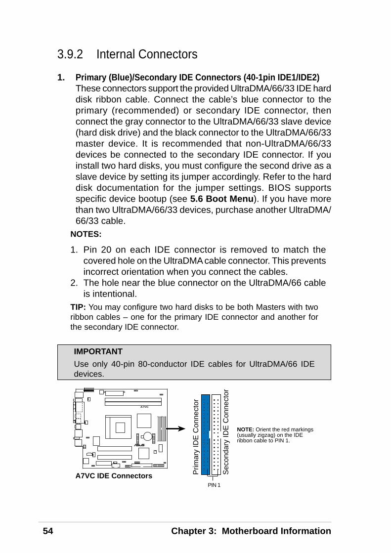
1. Primary (Blue)/Secondary IDE Connectors (40-1pin IDE1/IDE2)These connectors support the provided UltraDMA/66/33 IDE harddisk ribbon cable. Connect the cable’s blue connector to theprimary (recommended) or secondary IDE connector, thenconnect the gray connector to the UltraDMA/66/33 slave device(hard disk drive) and the black connector to the UltraDMA/66/33master device. It is recommended that non-UltraDMA/66/33devices be connected to the secondary IDE connector. If youinstall two hard disks, you must configure the second drive as aslave device by setting its jumper accordingly. Refer to the harddisk documentation for the jumper settings. BIOS supportsspecific device bootup (see 5.6 Boot Menu). If you have morethan two UltraDMA/66/33 devices, purchase another UltraDMA/66/33 cable.
NOTES:
1. Pin 20 on each IDE connector is removed to match thecovered hole on the UltraDMA cable connector. This preventsincorrect orientation when you connect the cables.
2. The hole near the blue connector on the UltraDMA/66 cableis intentional.
TIP: You may configure two hard disks to be both Masters with tworibbon cables – one for the primary IDE connector and another forthe secondary IDE connector.
A7VC
®
A7VC IDE Connectors
NOTE: Orient the red markings(usually zigzag) on the IDEribbon cable to PIN 1.
Prim
ary
IDE
Con
nect
or
Sec
onda
ry ID
E C
onne
ctor
PIN 1
3.9.2 Internal Connectors
IMPORTANT
Use only 40-pin 80-conductor IDE cables for UltraDMA/66 IDEdevices.

ASUS Terminator K7 Barebone System 55
2. USB Header (10-1 pin USBPORT)If the USB port connectors on the back panel are inadequate,one USB header is available for two additional USB portconnectors. Connect the USB header to a 2-port USB connectorset and mount the bracket to an open slot on the chassis. (TheUSB connector set does not come with the motherboardpackage.)
3. Infrared Module Connector (5-pin IR)This connector supports an optional wireless transmitting andreceiving infrared module. This module mounts to a small openingon a system chassis that supports this feature. You must alsoconfigure the setting through UART2 Use Infrared (see 5.4.2I/O Device Configuration) to select whether UART2 is directedfor use with COM2 or IrDA. Use the five pins as shown in BackView and connect a ribbon cable from the module to themotherboard SIR connector according to the pin definitions.
A7VC
®
A7VC USB Ports
US
B P
ower
US
BP
2–U
SB
P2+
GN
DN
C
US
B P
ower
US
BP
3–U
SB
P3+
GN
D15
610
USB1
A7VC
®
A7VC Infrared Module Connector
Back View
+5VIRTX
IRRX(NC)GND
Front View
IR
+5V
IRR
X
IRT
X
GN
D
1

56 Chapter 3: Motherboard Information
4. CPU and Chassis Fan ConnectorsThe two 3-pin fan connectors (CPU_FAN, CHA_FAN) supportcooling fans of 350mA (4.2 Watts) or less. Orient the fans so thatthe heat sink fins allow airflow to go across the onboard heatsink(s) instead of the expansion slots. The fan wiring and plugmay vary depending on the fan manufacturer. The red wire shouldbe positive while the black should be ground. Connect the fanplug to the board taking into consideration the polarity of theconnector.
NOTE: Use the “Rotation” signal only with a specially designed fanwith a rotation signal. The Rotations Per Minute (RPM) can bemonitored using ASUS PC Probe (see 4.3 Install the OperatingSystem).
5. IDE Activity LED (2-pin IDELED)This connector supplies power to the cabinet’s IDE activity LED.Read and write activity by devices connected to the Primary orSecondary IDE connectors cause the IDE LED to light up.
A7VC
®
A7VC 12-Volt Cooling Fan Power
CH_FAN
CPU_FAN
GND
Rotation+12V
GND
Rotation+12V
A7VC
®
A7VC IDE Activity LED
TIP: If the case-mounted LED does notlight, try reversing the 2-pin plug.
IDELED
WARNING!
The CPU and/or motherboard will overheat if there is no airflow acrossthe CPU and onboard heatsinks. Damage may occur to themotherboard and/or the CPU fan if these pins are incorrectly used.These are not jumpers, do not place jumper caps over thesepins.

ASUS Terminator K7 Barebone System 57
6. Internal Audio Connectors (4-1 pin CD_IN, MODEM)These connectors allow you to receive stereo audio input fromsound sources such as a CD-ROM. The MODEM connectorallows the onboard audio to interface with a voice modem cardwith a similar connector. It also allows the sharing of mono_in(such as a phone) and a mono_out (such as a speaker) betweenthe audio and a voice modem card.
7. ATX Power Supply Connector (20-pin block ATXPWR)This connector connects to an ATX power supply. The plug fromthe power supply fits in only one orientation because of the differenthole sizes. Find the proper orientation and push down firmly makingsure that the pins are aligned.
A7VC
®
+3.
3Vol
ts-1
2.0V
olts
Gro
und
Pow
er S
uppl
y O
nG
roun
dG
roun
dG
roun
d-5
.0 V
olts
+5.
0 V
olts
+5.
0 V
olts
Pow
er G
ood
+12
.0V
olts
+3.
3 V
olts
+3.
3 V
olts
Gro
und
+5.
0 V
olts
Gro
und
+5.
0 V
olts
Gro
und
+5V
Sta
ndby
A7VC ATX & Auxiliary Power Connectors
ATX12V
ATXPWR
+12V DCCOM
+12V DCCOM
A7VC
®
A7VC Internal Audio Connectors
CD (Black)MODEM
Right A
udio Channel
Left Audio C
hannelG
round
Modem-Out (from Modem)Ground
Modem-In (to Modem)
IMPORTANT
Make sure that the ATX power supply can supply at least 10mA onthe +5-volt standby lead (+5VSB). You may experience difficulty inturning the system ON if the power supply cannot support the load.For Wake-On-LAN support, the ATX power supply must supply atleast 720mA +5VSB.

58 Chapter 3: Motherboard Information
8. Floppy Disk Drive Connector (34-1 pin FLOPPY)This connector supports the provided floppy drive ribbon cable.After connecting the single end to the board, connect the twoplugs on the other end to the floppy drives. (Pin 5 is removed toprevent inserting in the wrong orientation when using ribboncables with pin 5 plugged).
A7VC
®
NOTE: Orient the red markings onthe floppy ribbon cable to PIN 1.
A7VC Floppy Disk DriveConnector
FLOPPY
PIN 1
9. Wake-On-LAN Connector (3-pin WOL_CON)This connector connects to a LAN card with a Wake-On-LANoutput, such as the ASUS PCI-L101 Ethernet card (see 7.Appendix). The connector powers up the system when a wakeuppacket or signal is received through the LAN card.
IMPORTANT: To use this feature, enable the Wake-On-LANfeature in BIOS (see 5.5.1 Power Up Control) and make surethat system has an ATX power supply with at least 720mA +5Vstandby power.
A7VC
®
A7VC Wake-On-LAN Connector
IMPORTANT: Requires an ATX powersupply with at least 720mA +5 voltstandby power
WOLCON
+5 Volt Standby PME
Ground

ASUS Terminator K7 Barebone System 59
A7VC
®
A7VC Wake-On-Ring Connector
WOR
Ring# Ground
12
10. Wake-On-Ring Connector (2-pin WOR)This connector connects to internal modem cards with a Wake-On-Ring output. The connector powers up the system when aringup packet or signal is received through the internal modemcard. NOTE: For external modems, Wake-On-Ring is detectedthrough the COM port.
11. LCD-TV Headers (18-pin, 18-1 pin LCDTV)These headers require an optional LCD module for LCD outputor a TV-out module for TV output.
A7VC
®
A7VC LCD-TV Headers
LCDTV
1LTVCL+3V
TVVSYNCGNDDD4DD3DD1GND
TV#/LCDPAL/NTSC#
GNDBLANK
TVHSYNCGNDDD2DD0
+5V
GNDDD11DD9DD7GNDDD5
+5VPCIRST#
DD10GNDDD8DD6
CLKOUT0GND
VSPCLK1
VSPD1
LCDTV_ON#
IMPORTANT
This feature requires that the Power Up On External Modem Actparameter is enabled (see 5.5.1 Power Up Control) and that thesystem has an ATX power supply with at least 720mA +5V standbypower.

60 Chapter 3: Motherboard Information
A7VC
®
A7VC Microphone Header
MIC21
MIC SignalMIC PWR
Head set Left channelGND
Head set Right channel
FLOUT
A7VC
®
A7VC IOC_MB Connector
®
CGAEX
COM1 GAME
IOC_DC
12. IOC_MB Connector (22-pin)This connects the motherboard to the CGAEX extension modulewhich contains the COM1 and GAME ports.
13. Internal Microphone (2-pin) and FLOUT (3-pin) ConnectorsThis connector allows you to connect chassis mountedmicrophone to the motherboard instead of having to attach anexternal microphone onto the ATX connectors. Connect the LineOut/Mic cable to the FLOUT/MIC2 connector.

ASUS Terminator K7 Barebone System 61
The following 20-pin PANEL illustration is for items 14-19.
14. System Power LED Connector (3-1 pin PWR.LED)This 3-1 pin connector connects to the system power LED. TheLED lights up when you turn on the system power, and blinkswhen the system is in sleep or soft-off mode.
15. System Warning Speaker Connector (4-pin SPEAKER)This 4-pin connector connects to the case-mounted speaker.
16. System Message LED Connector (2-pin MSG.LED)This 2-pin connector is for the system message LED that indicatesreceipt of messages from a fax/modem. The normal status forthis LED is ON, when there is no incoming data signal. The LEDblinks when there is data received. The system message LEDfeature requires an ACPI OS and driver support.
17. System Management Interrupt Connector (2-pin SMI)This 2-pin connector allows you to manually place the systeminto a suspend mode, or “Green” mode, where system activity isinstantly decreased to save power and to expand the life of certainsystem components. Attach the case-mounted suspend switchthis 2-pin connector.
18. ATX Power Switch / Soft-Off Switch Connector (2-pinPWR.SW)The system power is controlled by a momentary switch attachedto this connector. Pressing the button switches the systembetween ON and SLEEP, or ON and SOFT OFF, depending onthe BIOS or OS settings. Pressing the button while in the ONmode for more than 4 seconds turns the system off.
19. Reset Switch Connector (2-pin RESET)This 2-pin connector connects to the case-mounted reset switchfor rebooting the system without turning off the power switch.
A7VC
®
A7VC System Panel Connectors * Requires an ATX power supply.
PLED
Ground
TB_LED
PWR
+5 V
+5V
SpeakerG
round
+5 V
ExtSMI#
Ground
Reset
Ground
Ground
Reset SWK
eylockG
round
Power LED
Keyboard Lock SpeakerConnector
ATX PowerSwitch*SMI Lead
Message LED

62 Chapter 3: Motherboard Information
NOTES

ASUS Terminator K7 Barebone System 63
This chapter enumerates the contents ofthe support CD that comes with theTerminator Barebone System package.
Chapter 4
Su
pp
ort
CD

64 Chapter 4: Starting Up
You should always use the latest operating system and updates whenusing new hardware to ensure full compliance. You may use anyversion of Windows 98/ME/NT/2000/XP and OS/2 operating system(OS).
When you start Windows 98 for the first time after installing themotherboard, Windows 98 detects all the Plug-n-Play devices. Followthe Add New Hardware Wizard to install all the necessary devicedrivers. When prompted to restart, select No, then follow the normalsetup procedures on the screen.
To begin using the support CD, insert it into the CD-ROM drive. Thesupport installation menu should appear. If the menu does not appear,double-click or run D:\ASSETUP.EXE (assuming that your CD-ROMdrive is drive D).
4.1 Install the Operating System
4.1.1 Windows 98 First Time Installation
4.1.2 A7VC Motherboard Support CD
NOTE
The support CD contents are subject to change at any time withoutnotice.

ASUS Terminator K7 Barebone System 65
• VIA 4 in 1Drivers: This driver will automatically detect and installthe latest IDE Bus Master, VIA AGP Driver, IRQ Routing Driver,and the VIA INF Driver.
• VIA Tech VT8361/VT8601/VT8501: Installs the VIA Tech supportapplication for graphics controller.
• Advance AC’97 Drivers and Applications: Installs the PCI audiodrivers to activate the AC ‘97 compliant audio features.
• Realtek RTL8139C PCI Fast Ethernet NIC Driver: Installs theRealtek RTL8139C PCI Fast Ethernet NIC Driver.
• ASUS PC Probe V2.14.06: Installs a smart utility that can monitorthe computer fan, temperature, and voltages.
• ASUS Update V3.28.04: Installs the ASUS Update program. Thisprogram allows you download the latest version of Flash BIOSfrom the ASUS website. Before using ASUS Update, you shouldinstall a network card and a TCP/IP network driver.
• Microsoft DirectX 8.0a Driver: Installs the Microsoft Direct Driver.
4.1.3 Applications

66 Chapter 4: Starting Up
• PC-Cillin 2000 V7.51: Installs the PC-cillin virus protectionsoftware. View the online help for more information.
• ADOBE Acrobat Reader V5.0: Installs the Adobe Acrobat Readersoftware necessary to view user’s manuals in PDF format.
• Install Cyberlink Video and Audio Applications: InstallsCyberlink PowerPlayerSE, PowerDVD Trial, and CyberlinkVideoLive Mail.
NOTE: To see the following items, click on the arrow (pointing tothe right) on the lower right corner of the screen. To return to thefirst menu screen, click on the arrow (pointing to the left) on thelower right corner of the second screen.
• ASUS Screen Saver: Installs the ASUS monitor screen saver.
• Show Mainboard Information: Allows you to view informationabout the motherboard, such as product name, BIOS version,and CPU.
• Browse Support CD: Allows you to view the contents of thesupport CD.
• ReadMe: Allows you to view a list of the files included in the supportCD and ASUS contact information.
• Exit: Exits the CD installation menu.

ASUS Terminator K7 Barebone System 67
When ASUS PC Probe starts, a splash screen appears allowing youto select whether to show the screen again when you open PC Probeor not. To bypass this startup screen, clear the Show up in nextexecution check box.
To launch ASUS PC Probe, click the Windows Start button, point toPrograms, and then ASUS Utility, and then click Probe Vx.xx.
The PC Probe icon appears on the taskbar system tray indicatingthat ASUS PC Probe is running. Clicking the icon allows you to seethe status of your PC.
ASUS PC Probe is a convenient utility to continuously monitor yourcomputer system’s vital components, such as fan rotations, voltages,and temperatures. It also has a utility that lets you review usefulinformation about your computer, such as hard disk space, memoryusage, and CPU type, CPU speed, and internal/external frequenciesthrough the DMI Explorer.
4.2 ASUS PC Probe
4.2.1 Starting ASUS PC Probe

68 Chapter 4: Starting Up
4.2.2 Using ASUS PC ProbeMonitoringMonitor SummaryShows a summary of theitems being monitored.
Temperature MonitorShows the PC temperature(for supported processorsonly).
Temperature Warningthreshold adjustment
(Move the slider up to increase thethreshold level or down to decrease
the threshold level)
Fan MonitorShows the PC fan rotation.
Voltage MonitorShows the PC voltages.
Fan Warningthreshold adjustment
(Move the slider up to increase thethreshold level or down to decrease
the threshold level)

ASUS Terminator K7 Barebone System 69
SettingsLets you set threshold levelsand polling intervals or refreshtimes of the PC’s temperature,fan rotation, and voltages.
HistoryLets you record the monitoringactivity of a certain componentof your PC for future reference.
Hard DrivesShows the used and free spaceof the PC’s hard disk drives andthe file allocation table or filesystem used.
Fan ControlLets you enable/disable SmartFan Control. Smart Fan Controladjusts the fan speed automati-cally based on the current CPUtemperature and predefinedthreshold.
CPU Cooling System SetupLets you select when to enable software CPU
cooling. When When CPU Overheated is selected,the CPU cooling system is enabled whenever the
CPU temperature reaches the threshold value.

70 Chapter 4: Starting Up
Device SummaryShows a summary of devicespresent in your PC.
DMI ExplorerShows information pertinent tothe PC, such as CPU type, CPUspeed, and internal/external fre-quencies, and memory size.
UtilityLets you run programs outside ofthe ASUS Probe modules. To runa program, click Execute Pro-gram. NOTE: This feature is cur-rently unavailable.
MemoryShows the PC memory load,memory usage, and paging fileusage.

ASUS Terminator K7 Barebone System 71
4.2.3 ASUS PC Probe Task Bar Icon
Right clicking the PC Probeicon brings up a menu toopen or exit ASUS PC Probeand pause or resume allsystem monitoring.
When the ASUS PC Probesenses a problem with yourPC, portions of the ASUSPC Probe icon changes tored, the PC speaker beeps,and the ASUS PC Probemonitor appears.

72 Chapter 4: Starting Up
NOTES

ASUS Terminator K7 Barebone System 73
This chapter describes the power upsequence and gives details on how tochange the system settings using theBIOS setup menus.
Chapter 5
BIO
S In
form
atio
n

74 Chapter 5: BIOS Information
1. After making all the connections, replace the system case cover.
2. Be sure that all switches are off (in some systems, marked with).
3. Connect the power cord to the power supply located at the backof the system chassis.
4. Connect the power cord to a power outlet that is equipped with asurge protector.
5. Turn on the devices in the following order:a. Monitorb. External SCSI devices (starting with the last device on the chain)c. System power (For ATX power supplies, you need to switch on
the power supply as well as press the ATX power switch on thefront of the chassis.)
6. The power LED on the front panel of the system case lights up.For ATX power supplies, the system LED lights up when you pressthe ATX power switch. If the monitor complies with “green”standards or if it has a power standby feature, the monitor LEDmay light up or switch between orange and green after the systemLED does. The system then runs the power-on tests. While thetests are running, the BIOS beeps or additional messages appearon the screen. If you do not see anything within 30 seconds fromthe time you turn on the power, the system may have failed apower-on test. Recheck your jumper settings and connections orcall your retailer for assistance.
Award BIOS Beep Codes
Beep MeaningOne short beep when No error during POSTdisplaying logoLong beeps in an endless loopNo DRAM installed or detectedOne long beep followed by Video card not found or video cardthree short beeps memory badHigh frequency beeps when CPU overheatedsystem is working System running at a lower frequency
5.1 Powering Up the First Time

ASUS Terminator K7 Barebone System 75
7. At power on, hold down <Delete> to enter BIOS Setup. Followthe instructions in 5.1 Managing and Updating Your BIOS.
* Powering Off the Computer: You must first exit or shut downthe system before switching off the power switch. For ATX powersupplies, you can press the ATX power switch after exiting orshutting down the operating system. If you use Windows 9X, clickthe Start button, click Shut Down, and then click Shut down thecomputer? The power supply should turn off after Windows shutsdown.
NOTE: The message “You can now safely turn off your computer”does not appear when shutting down with ATX power supplies.

76 Chapter 5: BIOS Information
5.2.1 Upon First Use of the Computer SystemIt is recommended that you save a copy of the original motherboardBIOS along with a Flash Memory Writer utility (AFLASH.EXE) to abootable floppy disk in case you need to reinstall the BIOS later.AFLASH.EXE is a Flash Memory Writer utility that updates the BIOSby uploading a new BIOS file to the programmable flash ROM on themotherboard. This file works only in DOS mode. To determine theBIOS version of your motherboard, check the last four numbers ofthe code displayed on the upper left-hand corner of your screen duringbootup. Larger numbers represent a newer BIOS file.
1. Type FORMAT A:/S at the DOS prompt to create a bootablesystem disk. DO NOT copy AUTOEXEC.BAT and CONFIG.SYSto the disk.
2. Type COPY D:\AFLASH\AFLASH.EXE A:\ (assuming D is yourCD-ROM drive) to copy AFLASH.EXE to the boot disk you created.
NOTE: AFLASH works only in DOS mode. It does not work in theDOS prompt within Windows and does not work with certainmemory drivers that may be loaded when you boot from the harddrive. It is recommended that you reboot using a floppy disk.
3. Reboot the computer from the floppy disk.
NOTE: BIOS setup must specify “Floppy” as the first item in theboot sequence.
4. In DOS mode, type A:\AFLASH <Enter> to run AFLASH.
5.2 Managing and Updating Y our BIOS
IMPORTANT!
If the word “unknown” appears after Flash Memory:, the memorychip is either not programmable or is not supported by the ACPI BIOSand therefore, cannot be programmed by the Flash Memory Writerutility.

ASUS Terminator K7 Barebone System 77
5. Select 1. Save Current BIOS to File from the Main menu andpress <Enter>. The Save Current BIOS To File screen appears.
6. Type a filename and the path, for example, A:\XXX-XX.XXX andthen press <Enter>.

78 Chapter 5: BIOS Information
1. Download an updated ASUS BIOS file from the Internet (WWWor FTP) (see ASUS CONTACT INFORMATION on page 3 fordetails) and save to the disk you created earlier.
2. Boot from the disk you created earlier.3. At the “A:\” prompt, type AFLASH and then press <Enter>.4. At the Main Menu, type 2 and then press <Enter>. The Update
BIOS Including Boot Block and ESCD screen appears.5. Type the filename of your new BIOS and the path, for example,
A:\XXX-XX.XXX, and then press <Enter>.NOTE: To cancel this operation, press <Enter>.
6. When prompted to confirm the BIOS update, press Y to start theupdate.
5.2.2 Updating BIOS Procedures
WARNING!
Only update your BIOS if you have problems with your motherboardand you know that the new BIOS revision will solve your problems.Careless updating can result in your motherboard having moreproblems!

ASUS Terminator K7 Barebone System 79
7. The utility starts to program the new BIOS information into theflash ROM. The boot block will be updated automatically only whennecessary. This will minimize the chance that a failed updateprevents the system from booting up. When the programming isfinished, Flashed Successfully appears.
8. Follow the onscreen instructions to continue.
WARNING!
If you encounter problems while updating the new BIOS, DO NOTturn off the system since this might prevent your system from bootingup. Just repeat the process, and if the problem still persists, updatethe original BIOS file you saved to the disk above. If the Flash MemoryWriter utility was not able to successfully update a complete BIOSfile, the system may not boot. If this happens, the system will needservicing.

80 Chapter 5: BIOS Information
This motherboard supports a programmable EEPROM that can beupdated using the provided utility as described in 5.2 Managing andUpdating Your BIOS.
The utility is used if you are installing a motherboard, reconfiguringyour system, or prompted to “Run Setup”. This section describeshow to configure your system using this utility.
Even if you are not prompted to use the Setup program, at sometime in the future you may want to change the configuration of yourcomputer. For example, you may want to enable the SecurityPassword Feature or make changes to the power managementsettings. It will then be necessary to reconfigure your system usingthe BIOS Setup program so that the computer can recognize thesechanges and record them in the CMOS RAM of the EEPROM.
The EEPROM on the motherboard stores the Setup utility. When youstart up the computer, the system provides you with the opportunityto run this program. This appears during the Power-On Self Tests(POST). Press <Delete> to call up the Setup utility. If you are a littlebit late in pressing the mentioned key, POST continues to run thetest routine, thus preventing you from launching the Setup program.If you intend to enter Setup, restart the system by pressing <Ctrl> +<Alt> + <Delete>, or by pressing the Reset button on the systemchassis. You can also restart by turning the system off and then backon again. But do so only if the first two methods fail.
The Setup program is designed to make it as easy to use as possible.It is a menu-driven program, which means you can scroll through thevarious sub-menus and make your selections among thepredetermined choices.
To access the BIOS Setup program, press the <Delete> key after thePower-On Self Tests (POST).
5.3 BIOS Setup Program
NOTE: Because the BIOS software is constantly being updated, thefollowing BIOS setup screens and descriptions are for referencepurposes only, and may not exactly match what you see on yourscreen.

ASUS Terminator K7 Barebone System 81
5.3.1 BIOS Menu BarThe top of the screen has a menu bar with the following selections:
MAIN Use this menu to make changes to the basic system configu-ration.
ADVANCED Use this menu to enable and make changes to the ad-vanced features.
POWER Use this menu to configure and enable Power Manage-ment features.
BOOT Use this menu to configure the default system device usedto locate and load the Operating System.
EXIT Use this menu to exit the current menu or specify how to exitthe Setup program.
To access the menu bar items, press the right or left arrow key on thekeyboard until the desired item is highlighted.
5.3.2 Legend BarAt the bottom of the Setup screen you will notice a legend bar. The keys inthe legend bar allow you to navigate through the various setup menus. Thefollowing table lists the keys found in the legend bar with their correspondingalternates and functions.
Navigation Key(s) Function Description<F1> or <Alt + H> Displays the General Help screen from anywhere in the
BIOS Setup
<Esc> Jumps to the Exit menu or returns to the main menu froma sub-menu
¨ or Æ (keypad arrow) Selects the menu item to the left or right
or Ø (keypad arrow) Moves the highlight up or down between fields
- (minus key) Scrolls backward through the values for the highlightedfield
+ (plus key) or spacebar Scrolls forward through the values for thehighlighted field
<Enter> Brings up a selection menu for the highlighted field
<Home> or <PgUp> Moves the cursor to the first field
<End> or <PgDn> Moves the cursor to the last field
<F5> Resets the current screen to its Setup Defaults
<F10> Saves changes and exits Setup

82 Chapter 5: BIOS Information
General HelpIn addition to the Item Specific Help window, the BIOS setup programalso provides a General Help screen. This screen can be called upfrom any menu by simply pressing <F1> or the <Alt> + <H>combination. The General Help screen lists the legend keys with theircorresponding alternates and functions.
Saving Changes and Exiting the Setup ProgramSee 5.8 Exit Menu for detailed information on saving changes andexiting the setup program.
Scroll BarWhen a scroll bar appears to the right of a help window, it indicatesthat there is more information to be displayed that will not fit in thewindow. Use <PgUp> and <PgDn> or the up and down arrow keys toscroll through the entire help document. Press <Home> to displaythe first page, press <End> to go to the last page. To exit the helpwindow, press <Enter> or <Esc>.
Sub-MenuNote that a right pointer symbol (as shown onthe left ) appears to the left of certain fields.This pointer indicates that you can launch asub-menu from this field. A sub-menu containsadditional options for a field parameter. Todisplay a sub-menu, simply move the highlightto the field and press <Enter>. Use the legend
keys to enter values or move from field to field within a sub-menu justas you would within a menu. Use the <Esc> key to return to the mainmenu.
Take some time to familiarize yourself with each of the legend keysand their corresponding functions. Practice navigating through thevarious menus and sub-menus. If you accidentally make unwantedchanges to any of the fields, use the set default hot key <F5>. Whilemoving around through the Setup program, note that explanationsappear in the Item Specific Help window located to the right of eachmenu. This window displays the help text for the currently highlightedfield.
NOTE: The item heading in square brackets represents the defaultsetting for that field.

ASUS Terminator K7 Barebone System 83
When the Setup program is accessed, the following screen appears:
System Time [XX:XX:XX]Sets your system to the time that you specify (usually the currenttime). The format is hour, minute, second. Valid values for hour,minute and second are Hour: (00 to 23), Minute: (00 to 59), Sec-ond: (00 to 59). Use the <Tab> or <Shift> + <Tab> keys to movebetween the hour, minute, and second fields.
System Date [XX/XX/XXXX]Sets your system to the date that you specify (usually the currentdate). The format is month, day, year. Valid values for month, day,and year are Month: (1 to 12), Day: (1 to 31), Year: (100 year range).Use the <Tab> or <Shift> + <Tab> keys to move between the month,day, and year fields.
Legacy Diskette A [1.44M, 3.5 in.], Legacy Diskette B [None]Sets the type of floppy drives installed. Configuration options:[None] [1.44M, 3.5 in.]
Floppy 3 Mode Support [Disabled]This is required to support older Japanese floppy drives. TheFloppy 3 Mode feature allows reading and writing of 1.2MB (asopposed to 1.44MB) on a 3.5-inch diskette. Configuration options:[Disabled] [Enabled]
5.4 Main Menu

84 Chapter 5: BIOS Information
5.4.1 Primary & Secondary Master/Slave
NOTE: Before attempting to configure a hard disk drive, make sureyou have the configuration information supplied by the manufac-turer of the drive. Incorrect settings may cause your system to failto recognize the installed hard disk. To allow the BIOS to detectthe drive type automatically, select [Auto].
Type [Auto]Select [Auto] to automatically detect an IDE hard disk drive. If auto-matic detection is successful, the correct values will be filled in forthe remaining fields on this sub-menu. If automatic detection fails,your hard disk drive may be too old or too new. You can try updatingyour BIOS or enter the IDE hard disk drive parameters manually.
NOTE: After the IDE hard disk drive information has been enteredinto BIOS, new IDE hard disk drives must be partitioned (such aswith FDISK) and then formatted before data can be read from andwrite on. Primary IDE hard disk drives must have its partition set toactive (also possible with FDISK).
Other options for the Type field are:
[None] - to disable IDE devices

ASUS Terminator K7 Barebone System 85
[User Type HDD]
Manually enter the number of cylinders, heads and sectors per track foryour drive. Refer to your drive documentation or look on the drive for thisinformation. If no drive is installed or if you are removing a drive and notreplacing it, select [None].
Translation Method [LBA]Select the hard disk drive type in this field. When Logical Block Addressingis enabled, 28-bit addressing of the hard drive is used without regard forcylinders, heads, or sectors. Note that LBA Mode is necessary for driveswith greater than 504MB in storage capacity. Configuration options: [LBA][LARGE] [Normal] [Match Partition Table] [Manual]
CylindersThis field configures the number of cylinders. Refer to your drive documen-tation to determine the correct value to enter into this field. NOTE: To makechanges to this field, the Type field must be set to [User Type HDD] and theTranslation Method field must be set to [Manual].
IMPORTANT:
If your hard disk was already formatted on an older previous system,incorrect parameters may be detected. You will need to enter thecorrect parameters manually or use low-level format if you do notneed the data stored on the hard disk.
If the parameters listed differ from the ones used when the disk wasformatted, the disk will not be readable. If the auto-detectedparameters do not match the ones that should be used for your disk,you should enter the correct ones manually by setting [User TypeHDD].

86 Chapter 5: BIOS Information
HeadThis field configures the number of read/write heads. Refer to your drive docu-mentation to determine the correct value to enter into this field. NOTE: Tomake changes to this field, the Type field must be set to [User Type HDD] andthe Translation Method field must be set to [Manual].
SectorThis field configures the number of sectors per track. Refer to your drivedocumentation to determine the correct value to enter into this field. NOTE:To make changes to this field, the Type field must be set to [User TypeHDD] and the Translation Method field must be set to [Manual].
CHS CapacityThis field shows the drive’s maximum CHS capacity calculated automati-cally by the BIOS from the drive information you entered.
Maximum LBA CapacityThis field shows the drive’s maximum LBA capacity calculated automati-cally by the BIOS from the drive information you entered.
Multi-Sector Transfers [Maximum]This option automatically sets the number of sectors per block to the highestnumber supported by the drive. This field can also be configured manually.Note that when this field is automatically configured, the set value may notalways be the fastest value for the drive. Refer to the documentation thatcame with your hard drive to determine the optimal value and set it manually.NOTE: To make changes to this field, the Type field must be set to [UserType HDD]. Configuration options: [Disabled] [2 Sectors] [4 Sectors] [8 Sec-tors] [16 Sectors] [32 Sectors] [Maximum]
SMART Monitoring [Disabled]This allows the enabling or disabling of the S.M.A.R.T. (Self-Monitoring,Analysis and Reporting Technology) system which utilizes internal hard diskdrive monitoring technology. This feature is normally disabled because sys-tem resources used in this feature may decrease system performance.Configuration options: [Disabled] [Enabled]
PIO Mode [4]This option lets you set a PIO (Programmed Input/Output) mode for theIDE device. Modes 0 through 4 provide successively increased performance.Configuration options: [0] [1] [2] [3] [4]
Ultra DMA Mode [Disabled]Ultra DMA capability allows improved transfer speeds and data integrity forcompatible IDE devices. Set to [Disabled] to suppress Ultra DMA capabil-ity. NOTE: To make changes to this field, the Type field must be set to[User Type HDD]. Configuration options: [0] [1] [2] [3] [4] [Disabled]

ASUS Terminator K7 Barebone System 87
Boot Up NumLock Status [On]This field enables users to activate the Number Lock function uponsystem boot. Configuration options: [Off] [On]
Keyboard Auto-Repeat Rate [12/Sec]This controls the speed at which the system registers repeated key-strokes. Options range from 6 to 30 characters per second. Configu-ration options: [6/Sec] [8/Sec] [10/Sec] [12/Sec] [15/Sec] [20/Sec][24/Sec] [30/Sec]
Keyboard Auto-Repeat Delay [1/4 Sec]This field sets the time interval for displaying the first and secondcharacters. Configuration options: [1/4 Sec] [1/2 Sec] [3/4 Sec] [1Sec]
5.4.2 Keyboard Features
Other options for “Type:” are:
[CD-ROM] - for IDE CD-ROM drives[LS-120] - for LS-120 compatible floppy disk drives[ZIP-100] - for ZIP-100 compatible disk drives[MO] - for IDE magneto optical disk drives[Other ATAPI Device] - for IDE devices not listed here
After using the legend keys to make your selections on this sub-menu, pressthe <Esc> key to return to the Main menu. When the Main menu appears, youwill notice that the drive size appear in the field for the hard disk drive that youjust configured.

88 Chapter 5: BIOS Information
Halt On [All but Keyboard]This field determines which types of errors will cause the system to halt.Configuration options: [All Errors] [No Error] [All but Keyboard] [All but Disk][All but Disk/Keyboard]
Installed Memory [XXX MB]This display-only field displays the amount of conventional memory detectedby the system during bootup. You do not need to make changes to this field.
Supervisor Password [Disabled] / User Password [Disabled]These fields allow you to set the passwords. To set the password, highlight theappropriate field and press <Enter>. Type in a password and press <Enter>.You can type up to eight alphanumeric characters. Symbols and other keysare ignored. To confirm the password, type the password again and press the<Enter>. The password is now set to [Enabled]. This password allows fullaccess to the BIOS Setup menus. To clear the password, highlight this fieldand press <Enter>. The same dialog box as above will appear. Press <Enter>and the password will be set to [Disabled].A Note about PasswordsThe BIOS Setup program allows you to specify passwords in the Main menu. Thepasswords control access to the BIOS during system startup. The passwords arenot case sensitive. In other words, it makes no difference whether you enter apassword using upper or lowercase letters. The BIOS Setup program allows youto specify two separate passwords: a Supervisor password and a User pass-word. When disabled, anyone may access all BIOS Setup program functions.When enabled, the Supervisor password is required for entering the BIOS Setupprogram and having full access to all configuration fields.Forgot the Password?If you forgot the password, you can clear the password by erasing the CMOS RealTime Clock (RTC) RAM. The RAM data containing the password information ispowered by the onboard button cell battery. To erase the RTC RAM: (1) Unplugyour computer, (2) Short the solder points, (3) Turn ON your computer, (4) Holddown <Delete> during bootup and enter BIOS setup to re-enter user preferences.
A7VC
®
A7VC Clear RTC RAMShort solder pointsto Clear CMOS
CLRTC (R155)

ASUS Terminator K7 Barebone System 89
5.5 Advanced Menu
Operating Frequency Setting [User Define]This field allows you to configure the external frequency of your CPU.Select [User Define] if you want to make changes to the CPUFrequency field. When [Standard] is selected, CPU (external)Frequency will be fixed at 100MHz. Configuration options: [Standard][User Define]
CPU FrequencyThis feature tells the clock generator what frequency to send to thesystem bus and PCI bus. The bus frequency (external frequency)multiplied by the bus multiple equals the CPU speed (the CPU’s internalfrequency). Note that the frequency is already set to a default of 133MHz.
DRAM FrequencyThis field determines whether the memory clock frequency is set tobe in synchronous or asynchronous mode with respect to the CPUFrequency. This must be set in conjunction with CPU (external)Frequency to match the speed of your SDRAM. When you press<Enter> on this field, the first available option in the pop-up menuequals the CPU Frequency you select for the previous field, and thesecond available option is the CPU Frequency multiplied by 4/3. Tomaintain and ensure system stability, DRAM Frequency is set to[100 MHz] when the BIOS setup default settings are loaded/selected.

90 Chapter 5: BIOS Information
CPU Level 1 Cache, CPU Level 2 Cache [Enabled]These fields allow you to choose from the default of [Enabled] orchoose [Disabled] to turn on or off the CPU’s Level 1 and Level 2built-in cache. Configuration options: [Disabled] [Enabled]
CPU Level 2 Cache ECC Check [Disabled]This function controls the ECC capability in the CPU level 2 cache.Configuration options: [Disabled] [Enabled]
BIOS Update [Enabled]This functions as an update loader integrated into the BIOS to supplythe processor with the required data. In the default position of[Enabled], the BIOS will load the update on all processors duringsystem bootup. Configuration options: [Disabled] [Enabled]
PS/2 Mouse Function Control [Auto]The default of [Auto] allows the system to detect a PS/2 mouse onstartup. If detected, IRQ12 will be used for the PS/2 mouse. IRQ12will be reserved for expansion cards only if a PS/2 mouse is notdetected. [Enabled] will always reserve IRQ12, whether on startup aPS/2 mouse is detected or not. Configuration options: [Enabled] [Auto]
USB Legacy Support [Auto]This motherboard supports Universal Serial Bus (USB) devices. Thedefault of [Auto] allows the system to detect a USB device on startup.If detected, the USB controller will be enabled. If not detected, theUSB controller will be disabled. When this field is set to [Disabled],the USB controller is disabled no matter whether you are using aUSB device or not. Configuration options: [Disabled] [Enabled] [Auto]
OS/2 Onboard Memory > 64M [Disabled]When using OS/2 operating systems with installed DRAM of greaterthan 64MB, you need to set this option to [Enabled]; otherwise, leavethis on [Disabled]. Configuration options: [Disabled] [Enabled]

ASUS Terminator K7 Barebone System 91
5.5.1 Chip Configuration
Onboard PCI IDE Enable [Both]You can select to enable the primary IDE channel, secondary IDEchannel, both, or disable both channels. Configuration options: [Both][Primary] [Secondary] [Disabled]
Spread Spectrum Control [Enabled]Leave on default setting. Spread spectrum typically reduces systemelectromagnetic interference (EMI) by 8dB to 10dB.
SDRAM Configuration [By SPD]Sets the optimal timings for SDRAM related fields, depending on thememory modules you are using. Default setting is [By SPD], whichsets the subsequent 3 items by reading the contents in the SPD (SerialPresence Detect) device. The EEPROM on the memory modulestores critical parameter data, such as memory type, size, speed,voltage interface, and module banks. Configuration options: [UserDefine] [7ns(143MHz)] [8ns(125MHz)] [By SPD]
SDRAM CAS LatencyThis controls the latency between the SDRAM read command and thetime that the data actually becomes available. NOTE: This field willonly be adjustable when SDRAM Configuration is set to [User Define].
SDRAM RAS Precharge TimeThis controls the idle clocks after issuing a precharge command tothe SDRAM. NOTE: This field will only be adjustable when SDRAMConfiguration is set to [User Define].

92 Chapter 5: BIOS Information
SDRAM RAS to CAS DelayThis controls the latency between the SDRAM active command andthe read/write command. NOTE: This field will only be adjustablewhen SDRAM Configuration is set to [User Define].
PCI Master Read Caching [Disabled]Default: [Disabled]Leave on default setting. Configuration options: [Disabled] [Enabled]
Delayed Transaction [Disabled]Default: [Disabled]Leave on default setting. Enabled, this frees the PCI Bus when theCPU is accessing 8-bit ISA devices that normally consume about 50-60 PCI Clocks without PCI delayed transaction. Select [Disabled] forISA devices that are not PCI 2.1 compliant. Configuration options:[Disabled] [Enabled]
PCI to DRAM Prefetch [Enabled]Configuration options: [Disabled] [Enabled]
Byte Merge [Disabled]To optimize the data transfer on PCI, this merges a sequence ofindividual memory writes (bytes or words) into a single 32-bit block ofdata. However, byte merging may only be done when the bytes withina data phase are in a prefetchable address range. Configurationoptions: [Disabled] [Enabled]
DRAM Read Latch Delay [Auto]Configuration options: [-0.01 ns] [0.75 ns]...[Auto]
Memory Early/Delay Write [Auto]Configuration options: [0.0 ns] [0.5 ns]...[Auto]
DIMM Interleave Setting [Auto]Configuration options: [Auto] [Disabled]
VGA Shared Memory SizeThis size cannot exceed the last memory bank size in the system. Ifthere is only one DRAM bank in the system, this size is set to half ofthis DRAM bank size automatically.
Select Display Device<Enter> to select the display device for next boot.

ASUS Terminator K7 Barebone System 93
5.5.2 I/O Device Configuration
Onboard FDC Swap A & B [No Swap]This field allows you to reverse the hardware drive letter assignmentsof your floppy disk drives. Configuration options: [No Swap] [SwapAB]
Onboard Serial Port 1 [3F8H/IRQ4]Onboard Serial Port 2 [2F8H/IRQ3]These fields allow you to set the addresses for the onboard serialconnectors. Serial Port 1 and Serial Port 2 must have differentaddresses. Configuration options: [3F8H/IRQ4] [2F8H/IRQ3] [3E8H/IRQ4] [2E8H/IRQ10] [Disabled]
UART2 Use Infrared [Disabled]When enabled, this field activates the onboard standard infrared feature andsets the second serial UART to support the infrared module connector on themotherboard. If your system already has a second serial port connected to theonboard COM2 connector, it will no longer work if you enable the infrared feature.See Standard and Consumer Infrared Module Connector in 3.9.1 ExternalConnectors. Configuration options: [Disabled] [Enabled]

94 Chapter 5: BIOS Information
Onboard Parallel Port [378H/IRQ7]This field sets the address of the onboard parallel port connector. If you disablethis feature, Parallel Port Mode and ECP DMA Select configurations will notbe available. Configuration options: [Disabled] [378H/IRQ7] [278H/IRQ5]
Parallel Port Mode [ECP+EPP]This field allows you to set the operation mode of the parallel port. [Normal]allows normal-speed operation but in one direction only; [EPP] allowsbidirectional parallel port operation; [ECP] allows the parallel port to operate inbidirectional DMA mode; [ECP+EPP] allows normal speed operation in a two-way mode. Configuration options: [Normal] [ECP] [EPP] [ECP+EPP]
ECP DMA Select [3]This field allows you to configure the parallel port DMA channel for the selectedECP mode. This selection is available only if you select [ECP] or [ECP+EPP] inParallel Port Mode above. Configuration options: [1] [3]
Onboard Peripheral Resource Control
Onboard AC97 Audio Controller [Auto][Auto] allows the motherboard’s BIOS to detect whether you are usingany network/audio device. If a network/audio device is detected, theonboard network/audio controller will be enabled; if no network/audiodevice is detected, the onboard network/audio controller will bedisabled. If you have conflicts with the onboard network/audiocontroller, you may set the appropriate field to [Disabled].Configuration options: [Enabled] [Disabled]

ASUS Terminator K7 Barebone System 95
Onboard Legacy Audio Support [Disabled]The onboard chipset is integrated with a SoundBlaster Pro controller.To use it, you must enable this field. Leave on the default setting[Disabled] if you want to use an add-on audio device. NOTE: To displaythe rest of the setup items, this field must be enabled (as shownbelow).
Sound Blaster Emulation [Disabled]Select [Enabled] for this field if you want to use the Sound Blaster™emulation feature.
Sound Blaster I/O Base Address [220h-22Fh]Sound Blaster IRQ [IRQ5]Sound Blaster DMA [DMA 1]These fields set the I/O address, IRQ, and DMA channel for the SoundBlaster™ feature.
MPU 401 [Enabled]Enable this field if you want to use the MIDI device onboard.
MPU 401 I/O Base Address [300h-303h]This sets the I/O address for the onboard MIDI device.
FM Enable (388h-38Bh) [Disabled]This field enables or disables the FM modulation feature.
Game Port Function [Disabled]Enable this field to use the game port. Configuration options:[Disabled] [Enable (200h-207h)]

96 Chapter 5: BIOS Information
5.5.3 PCI Configuration
Slot 1, Slot 2, IRQ [Auto]These fields set how IRQ use is determined for each PCI slot. Thedefault setting for each field is [Auto], which utilizes auto-routing todetermine IRQ use. Configuration options: [Auto] [NA] [3] [4] [5] [7][9] [10] [11] [12] [14] [15]
PCI/VGA Palette Snoop [Disabled]Some nonstandard VGA cards, such as graphics accelerators orMPEG video cards, may not show colors properly. The setting[Enabled] should correct this problem. Otherwise, leave this on thedefault setting of [Disabled]. Configuration options: [Disabled][Enabled]
PCI Latency Timer [32]Leave on default setting for best performance vs. stability.
SYMBIOS SCSI BIOS [Auto][Auto] allows the motherboard’s BIOS to detect whether you have aSymbios SCSI card. If the Symbios SCSI card is detected, themotherboard’s Symbios BIOS will be enabled; if no Symbios SCSIcard is detected, the onboard Symbios SCSI BIOS will be disabled.
[Disabled] will disable the motherboard’s Symbios SCSI BIOS sothat the BIOS on an add-on Symbios SCSI card can be used. If yourSymbios SCSI card does not have a BIOS, the Symbios SCSI cardwill not function. Configuration options: [Auto] [Disabled]

ASUS Terminator K7 Barebone System 97
USB Function [Enabled]This motherboard supports Universal Serial Bus (USB) devices. Setto [Enabled] if you want to use USB devices. Configuration options:[Disabled] [Enabled]
Primary VGA BIOS [PCI Card]If your computer has both PCI and AGP VGA cards, this field allowsyou to select which of the cards will act as your primary graphicscard. [AGP Card] uses the AGP card as your primary card. The default,[PCI Card], allows your PCI graphics card to take precedence whendetected. Configuration options: [PCI Card] [AGP Card]
PCI/PNP IRQ Resource Exclusion
IRQ XX Reserved for Legacy Device [No/ICU]These fields indicate whether or not the displayed IRQ for each fieldis being used by an onboard legacy (non-PnP) device. The defaultvalue indicates either that the displayed IRQ is not used or that ISAConfiguration Utility (ICU) is being used to determine if a legacy deviceis using that IRQ. Configuration options: [No/ICU] [Yes]

98 Chapter 5: BIOS Information
PCI/PNP DMA Resource Exclusion
DMA x Reserved for Legacy Device [No/ICU]These fields indicate whether or not the displayed DMA channel foreach field is being used by an onboard legacy (non-PnP) device.The default setting indicates either that the displayed DMA channelis not used or an ICU is being used to determine if an ISA device isusing that channel. Configuration options: [No/ICU] [Yes]

ASUS Terminator K7 Barebone System 99
PCI/PNP UMB Resource Exclusion
Reserved MEM Block BASE [No/ICU]This field allows you to set the base address and block size of anonboard legacy ISA device that uses any memory segment withinthe C800 and DFFF address range. If you have such a device andyou are not using an ICU to specify its address range, select a baseaddress from the six available options; the Reserved MEM BlockSIZE field will then appear for selecting the block size. If you havemore than one legacy device onboard that requires the use of thisaddress range, you can increase the block size to 8K, 16K, 32K, or64K. If you are using an ICU to accomplish this task, leave ReservedMEM Block BASE to its default setting of [No/ICU]. Configurationoptions: [No/ICU] [C800] [CC00] [D000] [D400] [D800] [DC00]

100 Chapter 5: BIOS Information
5.5.4 Shadow Configuration
Video ROM BIOS Shadow [Enabled]This field allows you to change the video BIOS location from ROM toRAM. Relocating to RAM enhances system performance, asinformation access is faster than the ROM. Configuration options:[Disabled] [Enabled]
C8000-DFFFF Shadow [Disabled]These fields are used for shadowing other expansion card ROMs. Ifyou install other expansion cards with ROMs on them, you will needto know which addresses the ROMs use to shadow them specifically.Shadowing a ROM reduces the memory available between 640Kand 1024K by the amount used for this purpose. Configuration options:[Disabled] [Enabled]

ASUS Terminator K7 Barebone System 101
The Power menu allows you to reduce power consumption. This feature turnsoff the video display and shuts down the hard disk after a period of inactivity.
Power Management [User Defined]This option must be enabled to use any of the automatic power saving fea-tures. If this menu item is set to [Disabled], power management features willnot function regardless of other field settings on this menu. The [User De-fine] option allows you to make your own selections in the Power menu.When set to [Max Saving], system power will be conserved to its greatestamount. The Suspend Mode field will then be set to predefined value thatensures maximum power savings.
This field acts as the master control for the power management modes. [MaxSaving] puts the system into power saving mode after a brief period of sys-tem inactivity; [Min Saving] is almost the same as [Max Saving] except thatthe system inactivity period is longer; [Disabled] disables the power savingfeatures; [User Define] allows you to set power saving options according toyour preference. Configuration options: [User Define] [Disabled] [Min Sav-ing] [Max Saving]
5.6 Power Menu

102 Chapter 5: BIOS Information
Video Off Option [Suspend -> Off ]This field determines when to activate the video off feature for monitorpower management. Configuration options: [Always On] [Suspend -> Off]
Video Off Method [DPMS OFF]This field defines the video off features. The DPMS (Display PowerManagement System) feature allows the BIOS to control the videodisplay card if it supports the DPMS feature. [Blank Screen] only blanksthe screen (use this for monitors without power management or “green”features. If set up in your system, your screen saver does not run with[Blank Screen] selected). [V/H SYNC+Blank] blanks the screen andturns off vertical and horizontal scanning. Configuration options: [BlankScreen] [V/H SYNC+Blank] [DPMS Standby] [DPMS Suspend] [DPMSOFF] [DPMS Reduce ON]
HDD Power Down [Disabled]Shuts down any IDE hard disk drives in the system after a period ofinactivity as set in this user-configurable field. This feature does notaffect SCSI hard drives. Configuration options: [Disabled] [1 Min] [2Min] [3 Min]...[15 Min]
Suspend-to-RAM Capability [Disabled]Suspend-to-RAM (STR) is an energy-saving feature. In Suspend-to-RAM state, all devices on the computer are turned off, except for thesystem RAM. Thus, the PC only consumes less than 5 watts of power.Select [Enabled] if your power supply can provide at least 720mA onthe +5VSB lead to support the STR function. If the expansion cardyou use on the motherboard do not support the STR function, youmust leave this field to the default setting [Disabled]. Note that thisfield is only effective if you are using Windows 98. Configurationoptions: [Enabled] [Disabled]
IMPORTANT
Advanced Power Management (APM) should be installed to keepthe system time updated when the computer enters suspend modeactivated by the BIOS Power Management. For DOS environments,you need to add the statement, DEVICE=C:\DOS\POWER.EXE, toyour CONFIG.SYS file. For Windows 3.x and Windows 95, you needto install Windows with the APM feature. For Windows 98 and later,APM is automatically installed. A battery and power cord icon labeled“Power Management” appears in the “Control Panel.” Choose“Advanced” in the Power Management Properties dialog box.

ASUS Terminator K7 Barebone System 103
5.6.1 Power Up Control
Suspend Mode [Disabled]Sets the time period before the system goes into suspend mode.Configuration options: [Disabled] [30 Sec] [1 Min] [2 Min]...[1 Hour]
PWR Button < 4 Secs [Soft Off]When set to [Soft off], the ATX switch can be used as a normal sys-tem power-off button when pressed for less than 4 seconds. [Sus-pend] allows the button to have a dual function where pressing lessthan 4 seconds will place the system in sleep mode. Regardless ofthe setting, holding the ATX switch for more than 4 seconds will poweroff the system. Configuration options: [Soft off] [Suspend]Suspend-to-RAM Capability [Disabled]
AC PWR Loss Restart [Disabled]This allows you to set whether you want your system to reboot afterthe power has been interrupted. [Disabled] leaves your system offand [Enabled] reboots your system. [Previous State] sets your systemback to the state it is before the power interruption. Configurationoptions: [Disabled] [Enabled] [Previous State]

104 Chapter 5: BIOS Information
PWR Up On External Modem Act [Disabled]This allows either settings of [Enabled] or [Disabled] for powering upthe computer when the external modem receives a call while thecomputer is in Soft-off mode. NOTE: The computer cannot receiveor transmit data until the computer and applications are fully running.Thus connection cannot be made on the first try. Turning an externalmodem off and then back on while the computer is off causes aninitialization string that will also cause the system to power on.Configuration options: [Disabled] [Enabled]
Wake On LAN or PCI Modem [Disabled]Wake-On-LAN/PCI Modem allows your computer to be booted fromanother computer via a network by sending a wake-up frame or signal.Configuration options: [Disabled] [Enabled]
Wake onUSB for S3/S4/S5 State [Disbled]This allows you to select whether or not to wake up from S3/S4/S5by USB device. When selecting [Enable], make sure that jumper JP1Ais placed at 2-3 and the +5VSB standby power is larger than 2.0A.Otherwise, STR will not work properly.
Automatic Power Up [Disabled]This allows an unattended or automatic system power up. You mayconfigure your system to power up at a certain time of the day byselecting [Everyday] or at a certain time and day by selecting [ByDate]. Automatic Power Up does not work if the system is powereddown by operating systems with ACPI feature, such as Windows 98.Configuration options: [Disabled] [Everyday] [By Date]
IMPORTANT:
This feature requires an optional network interface with Wake-On-LAN and an ATX power supply with at least 720mA +5V standby power.

ASUS Terminator K7 Barebone System 105
5.6.2 Hardware Monitor
Power Supply Temperature [xxxC/xxxF]The onboard hardware monitor is able to detect the MB (motherboard)and CPU temperatures. Set to [Ignore] only if necessary.
CPU Fan Speed [xxxxRPM] / Chassis Fan Speed [xxxxRPM]The onboard hardware monitor is able to detect the CPU fan speedand the chassis fan speed in rotations per minute (RPM). Thepresence of the fans is automatically detected. Set to [Ignore] only ifnecessary.
VCORE Voltage, +3.3V Voltage, +5V Voltage, +12V Voltage [xx.xxV]686A VoltageThe onboard hardware monitor is able to detect the voltage outputby the onboard voltage regulators. Set to [Ignore] only if necessary.
NOTE: If any of the monitored items is out of range, an error messagewill appear: “Hardware Monitor found an error. Enter Power setupmenu for details”. You will then be prompted to “Press F1 to continue,DEL to enter SETUP”.

106 Chapter 5: BIOS Information
Boot SequenceThe Boot menu allows you to select among the four possible types ofboot devices listed using the up and down arrow keys. By using the<+> or <Space> key, you can promote devices and by using the <->key, you can demote devices. Promotion or demotion of devices altersthe priority which the system uses to search for a boot device on systempower up. Configuration fields include Removable Devices, IDE HardDrive, ATAPI CD-ROM, and Other Boot Device.
Removable Device [Legacy Floppy]Configuration options: [Disabled] [Legacy Floppy] [LS120] [ZIP][ATAPI MO] [USB FDD] [USB ZIP]
IDE Hard DriveThis field allows you to select which IDE hard disk drive to use in theboot sequence. Pressing [Enter] will show the product IDs of allconnected IDE hard disk drives.
ATAPI CD-ROMThis field allows you to select which ATAPI CD-ROM drive to use inthe boot sequence. Pressing [Enter] will show the product IDs of allyour connected ATAPI CD-ROM drives.
5.7 Boot Menu
IMPORTANT
Make sure the ATAPI CD-ROM drive that you want to use in the bootsequence is connected to either the PRIMARY or SECONDARY IDEconnectors, not to the ATA100 connectors. Currently, the Promise®Ultra DMA/100 chip does not support this feature.

ASUS Terminator K7 Barebone System 107
Other Boot Device Select [INT18 Device (Network)]Configuration options: [Disabled] [SCSI/Onboard ATA Boot Device][INT18 Device (Network)]
Plug & Play O/S [No]This field allows you to use a Plug-and-Play (PnP) operating systemto configure the PCI bus slots instead of using the BIOS. When [Yes]is selected, interrupts may be reassigned by the OS. When a non-PnP OS is installed or you want to prevent reassigning of interruptsettings, select the default setting of [No]. Configuration options: [No][Yes]
Reset Configuration Data [No]The Extended System Configuration Data (ESCD) contain informationabout non-PnP devices. It can also hold the complete record of howthe system was configured the last time it was booted. Select [Yes]only if you want to clear these data during the Power-On Self Test(POST). Configuration options: [No] [Yes]
Boot Virus Detection [Enabled]This field allows you to set boot virus detection, ensuring a virus-freeboot sector. The system halts and displays a warning message whenit detects a virus. If this occurs, you can either allow the operation tocontinue or use a virus-free bootable floppy disk to restart andinvestigate your system. Configuration options: [Disabled] [Enabled]
Quick Power On Self Test [Enabled]This field speeds up the Power-On-Self Test (POST) routine byskipping retesting a second, third, and fourth time. Configurationoptions: [Disabled] [Enabled]
Boot Up Floppy Seek [Disabled]When enabled, the BIOS will seek the floppy disk drive to determinewhether the drive has 40 or 80 tracks. Configuration options: [Disabled][Enabled]
Onboard LAN Boot ROMThis system configuration is originally set to [Disabled]
APIC ModeThis function supports the operating system in multiprocessing (MPOS). Configuration options: [Enabled] [Disabled]

108 Chapter 5: BIOS Information
Once you have made all of your selections from the various menus in theSetup program, you should save your changes and exit Setup. Select Exitfrom the menu bar to display the following menu:
Exit Saving ChangesOnce you are finished making your selections, choose this optionfrom the Exit menu to ensure the values you selected are saved tothe CMOS RAM. The CMOS RAM is sustained by an onboard backupbattery and stays on even when the PC is turned off. Once this op-tion is selected, a confirmation is asked. Select [Yes] to save changesand exit.
NOTE: If you attempt to exit the Setup program without saving yourchanges, the program prompts you with a message asking if youwant to save your changes before exiting. Pressing <Enter> savesthe changes while exiting.
Exit Discarding ChangesThis option should only be used if you do not want to save the changesyou have made to the Setup program. If you have made changes tofields other than system date, system time, and password, the sys-tem asks you to confirm the changes before exiting.
NOTE: Pressing <Esc> does not exit this menu. You must select oneof the options from this menu or <F10> from the legend bar to exitthis menu.
5.8 Exit Menu

ASUS Terminator K7 Barebone System 109
Load Setup DefaultsThis option allows you to load the default values for each of the pa-rameters on the Setup menus. When this option is selected or if <F5>is pressed, a confirmation is requested. Select [Yes] to load defaultvalues. You can now select Exit Saving Changes or make otherchanges before saving the values to the non-volatile RAM.
Discard ChangesThis option allows you to discard the selections you made and re-store the values you previously saved. After selecting this option, aconfirmation is requested. Select [Yes] to discard any changes andload the previously saved values.
Save ChangesThis option saves your selections without exiting the Setup program.You can then return to other menus and make changes. After select-ing this option, all selections are saved and a confirmation is re-quested. Select [Yes] to save any changes to the non-volatile RAM.

110 Chapter 5: BIOS Information
NOTES