01 ft cover/toc - ccn hvac control systems view operation manual.pdf · polling a ccn bus ......
TRANSCRIPT
This document is the property of Carrier Corporation and is delivered on the express condition that it is not to be disclosed,reproduced in whole or in part, or used for manufacture by anyone other than Carrier Corporation without its written consent, andthat no right is granted to disclose or so use any information contained in said document.
Carrier reserves the right to change or modify the information or product described without prior notice and without incurring anyliability.
© 2003, Carrier Corporation Printed in U.S.A. 808-239 Rev. 01/03
ComfortVIEW ™
OperationManual
Adding/Modifying CCNs ...................................... 39To Add a New CCN ..................................... 39Modifying CCNs .......................................... 49
Adding/Modifying Areas ...................................... 54To Add a New Area ..................................... 52To Modify an Existing AreaName ............................................................ 55
Deleting CCNs and Areas ..................................... 56To Delete a CCN .......................................... 56To Delete an Area ........................................ 57
Displaying the Controller List ............................... 58Sorting the Controller List ........................... 59Moving the Split Bar .................................... 59
Adding/Modifying Controllers ............................. 60To Add a New Controller ............................. 60To Modify an ExistingController's Name or Sort Key ..................... 66
Deleting Controllers .............................................. 69Viewing Status Display and MaintenanceTables ................................................................... 70
Table Jumps from Status Displayand Maintenance Tables ............................... 70Reference Jumps fromComfort Controller StatusDisplay Tables .............................................. 70Status Display andMaintenance Table Format .......................... 74Moving Around a Worksheet ....................... 76Adjusting and HidingWorksheet Columns andRows ............................................................. 76Displaying Point IDs .................................... 77Trend Wizard ............................................... 77Alarm Wizard ............................................... 78Report Wizard .............................................. 78
Viewing Configuration Tables .............................. 78Configuration Table Format ......................... 80<< and >> Buttons ....................................... 80
Introduction ............................................................... 1About this Manual ................................................... 2
Intended Audience ......................................... 2Description of Chapters ................................. 2Standards Used Throughout this Manual ....... 3Sample — To Attach a Note to MultipleAlarms ............................................................ 5Related Documentation .................................. 6
Power Up ................................................................. 6Logging In toWindows ........................................................ 6Logging Out of Windows .............................. 7Windows XP and Fast User Switching .......... 7
Logging In ............................................................... 8Logging Out .......................................................... 10Using ComfortVIEW: An Overview ................... 13
Using the Mouse .......................................... 13Using the Keyboard ..................................... 14
Interpreting ComfortVIEW Windows................... 18ComfortVIEW Menus and CommandLists ....................................................................... 21
Command MenuConventions ................................................. 22To Select a Command UsingYour Mouse .................................................. 23To Select a Command UsingYour Keyboard ............................................. 23Dialog Boxes ................................................ 23
Using ComfortVIEW Help ................................... 25Help Wizards ................................................ 25
Carrier Network Manager ...................................... 27Terminology .......................................................... 29Accessing the Carrier Network Manager .............. 32
The Controller List ....................................... 34Short Cut ...................................................... 32Carrier Network ManagerToolbar ......................................................... 36
Changing the Font ................................................. 38
ii
Viewing UT203 FID ServiceConfiguration Tables .................................... 80Table Jumps from Configuration Tables ...... 80Comfort Controller ReferenceJumps ........................................................... 81
Viewing Alarm History Tables ............................. 81Polling a CCN Bus ................................................ 82
Basic Bus Scan ............................................. 89System Summary ......................................... 90
Modifying (Forcing) Status Display orMaintenance Table Values .................................... 92
Forcing a Point ............................................. 92Autoing a Point ............................................ 94To Modify Point Descriptions ...................... 96To Copy and Paste Cell Data ....................... 96
Modifying Configuration Table Values ................ 97Drag and Drop .............................................. 98Speedy Data Entry ..................................... 101Modifying ConfigurationDecision Descriptions ................................ 103Copying and Pasting CellData ............................................................ 103
Modifying Table Names and Descriptions ........ 104Alternate Method ....................................... 106
Copying and Moving ControllerConfiguration Data .............................................. 107
Copying Controllers ................................... 107Moving Controllers .................................... 112
Verifying Controller Configuration AgainstYour Database ..................................................... 114Downloading ComfortVIEW Data toControllers ........................................................... 115
To Download an EntireController ................................................... 115To Download a SpecificTable ........................................................... 116
Uploading Controller Data toComfortVIEW ..................................................... 116
To Upload an EntireController ................................................... 117To Upload a Specific Table........................ 117
Modifying and Sending Time and Date .............. 118Displaying and Configuring CCN Options ......... 120
To Add a New Consumable or RuntimeOption Table .............................................. 123To Add a New HistoryOption Table .............................................. 124To Display and ModifyOption Configuration Tables ..................... 125To Modify an Option TableDescription ................................................. 126To Delete any Option Table ....................... 127
Configuring UT203 FIDs .................................... 128
Configuring Comfort Controllers ........................ 132Important Featuresand Considerations ..................................... 132Recovering fromDatabase Mismatch .................................... 133Use of Other UserInterfaces to ProgramComfort Controllers ................................... 133Procedure Overview ................................... 134Creating and ModifyingHardware and Software Points ................... 139Creating and ModifyingOther Database Objects: Setpoints,System Tables, Alarms,Functions, Algorithms ................................ 146Creating MultipleSimilarly-NamedDatabase Objects ........................................ 149Configuring DatabaseObjects ....................................................... 153List Entry .................................................... 153Table Jumps fromConfiguration Tables .................................. 155Reference Jumps fromConfiguration Tables .................................. 156Downloading ComfortVIEWData to a Comfort Controller ..................... 158Viewing or Modifying Best ++Tables ......................................................... 161
Exporting Controller Configuration Data ........... 163Dedicating Autodial Gateways to aSpecific Operation ............................................... 166Connecting to a Remote CCNUsing an Autodial Gateway ................................ 169Disconnecting from Remote CCNs ..................... 170Printing Carrier Network Manager Data ............. 171
To Print the SystemOverview or TableWindow Report .......................................... 171To Print a ControllerList Report .................................................. 172To Print a ControllerDatabase Report ......................................... 172
Sharing ComfortVIEW Dynamic Datawith Other Applications (DDE) .......................... 175
What Data can be Sent? ............................. 175Required Conditions for Successful DataSharing ....................................................... 175Linking Controller PointData to Applications thatSupport Paste Link ..................................... 175Linking Controller Point
Data to Applications thatDo Not Support Paste Link ........................ 175Linking Alarm Messages toOther Applications ..................................... 178DDE Poke .................................................. 178
Carrier Network Manager CommandSummary ............................................................. 179
File Menu ................................................... 181Edit Menu ................................................... 182Access Menu .............................................. 184Configure Menu ......................................... 185Configure Menu ......................................... 189CCN Tools Menu ....................................... 191Options Menu ............................................. 193Options Menu ............................................. 195Window Menu ............................................ 198Help Menu .................................................. 200
Remote Site Manager ............................................. 201Introduction ......................................................... 202
Required Conditions for a SuccessfulConnection ................................................. 202
Connecting to a RemoteComfortVIEW Server ......................................... 205
Disconnecting from a Remote ComfortVIEWServer Workstation .................................... 208Adding a Site to the ComfortVIEWRemote Site List ......................................... 209Deleting a Site from the ComfortVIEWRemote Site List ......................................... 212
WorkSPACE Manager ......................................... 213Terminology ........................................................ 214Accessing the WorkSPACE Manager ................. 216
Design Mode Versus RunMode .......................................................... 216To Launch the WorkSPACEManager Application andOpen an ExistingWorkSPACE .............................................. 217General Operation ...................................... 219Menu Bar .................................................... 219Drop Down List ......................................... 221WorkSPACE ManagerToolbar ....................................................... 221Bookmarks ................................................. 224
Displaying and Using Trends .............................. 225To Launch the WorkSPACEManager Application andDisplay a Trend in RunMode .......................................................... 226Status Bar ................................................... 229
To Display a Point’s Rangein the Y-Axis .............................................. 229To Display a Trend Value ata Selected Time .......................................... 229To Stop (Pause) a Trend ............................. 229To Start or Re-start a Trend ....................... 230To View or Modify TrendData Point Parameters andTrend History ............................................. 231To Save Trend Data to a File ..................... 232
Displaying and Using a ViewSPACE ................. 233To Launch the WorkSPACEManager Application andDisplay a ViewSPACE inRun Mode ................................................... 233To View a Data Box’s PointName and Description ................................ 235To View or Modify DataPoint Parameters and Values ...................... 235To Add a New Data Box ............................ 236To Jump to a LinkedWorkSPACE .............................................. 241To Share ViewSPACE Datawith Other Applications(DDE) ......................................................... 241Alarm Wizard ............................................. 243Trend Wizard ............................................. 244Report Wizard ............................................ 244
Creating a New WorkSPACE ............................. 245WorkSPACE Cloning ................................ 246Modifying an Existing WorkSPACE ......... 251Deleting a WorkSPACE............................. 253Creating a New ViewSPACE .................... 255
Overview of the Process .................. 255Graphic BackgroundDrawing Specifications ................... 255Step-by-step Instructions ................. 256
Modifying An Existing ViewSPACE ........ 272To Modify the ViewSPACEName ............................................... 272To Modify Data BoxParameters, Location, andSize .................................................. 273To Delete a Data Box orLink Area ......................................... 274To Add a New Data Box ................. 275To Add a New Link Area ................ 275To Modify a Link Area ................... 275To Save the ModifiedViewSPACE .................................... 276
Creating Tabular Data Box Displays ......... 277To Exit the Tabular Displayand Re-Size Data Boxes .................. 278
iii
Deleting/Removing ViewSPACEs ............ 278To Delete a ViewSPACE ................ 278To Remove a ViewSPACE ............. 278
Creating and Modifying Trends ................. 279To Save the Trend ........................... 282To Display the New orModified Trend in RunMode ................................................ 283
Deleting/Removing Trends ........................ 288To Delete a Trend ............................ 288To Remove a Trend ......................... 289
Connecting to/Disconnecting froma Remote CCN ........................................... 290
To Disconnect froma Remote CCN ................................ 292
Printing ViewSPACEs and Trends ............ 294Run Mode — Printing aViewSPACEor Trend Window ....................................... 294Design Mode — Printing aViewSPACE or TrendWindow or Printing aWorkSPACE,ViewSPACE, or TrendDefinition Report ....................................... 295
Animated Data Box Frame CreationGuidelines ........................................................... 298
Animated GraphicSpecifications ............................................. 299
WorkSPACE Manager Menu CommandSummary ............................................................. 301
File Menu — Design Mode ....................... 301File Menu — Run Mode ............................ 304Edit Menu — Design Mode ....................... 307Edit Menu — Run Mode ............................ 309Configure Menu — Design Mode ............. 311Configure Menu — Run Mode .................. 313Run Menu — Run Mode ............................ 314Run Menu — Design Mode ....................... 315Options Menu — Run Mode ...................... 316Options Menu — DesignMode .......................................................... 318Window Menu — RunMode .......................................................... 319Window Menu — DesignMode .......................................................... 321Help Menu — Run andDesign Mode .............................................. 321
Alarm Manager ..................................................... 323Terminology ........................................................ 324Introduction ......................................................... 325Alarm Indication Methods .................................. 326
Critical Alarm IndicationOption ......................................................... 327Specifying Your AlarmIndication Preference ................................. 327
Viewing New and Unacknowledged Alarms ...... 328Flashing Icon AlarmViewing ...................................................... 328Pop-up Window AlarmViewing ...................................................... 329
Viewing the Alarm List ....................................... 330The Alarm Menu ........................................ 331The Toolbars .............................................. 331Alarm Message Format .............................. 333The Status Bar ............................................ 335
Changing the Font ............................................... 336Updating the Alarm List ..................................... 337Sorting the Alarm List ......................................... 338Selecting Alarms ................................................. 340
Selecting One or MoreMessages .................................................... 340Selecting All Messages .............................. 340
Acknowledging Alarms ..................................... 341Acknowledging One AlarmMessage ...................................................... 341Acknowledging More ThanOne or All Alarm Messages ....................... 342
Attaching an Operator’s Note to an Alarm ......... 343To View, Modify, or Attacha Note to One Alarm .................................. 343To Attach the Same Note toMultiple Alarms ......................................... 343
Suppressing Alarms ........................................... 346To Enable or Disable AlarmSuppression ................................................ 346To View Suppressed Alarms ...................... 347
Deleting Alarms .................................................. 349Printing the Alarm List ....................................... 350
To Select Which AlarmMessage Components toPrint ............................................................ 350To Print Selected AlarmMessages .................................................... 351To Print All Alarm Messages ..................... 352To Automatically PrintAlarms on Occurrence ................................ 352
Assigning Custom Messages to IncomingAlarms ................................................................. 353
Rules for Custom MessageAttachment ................................................. 353Adding, Modifying, orDeleting a Custom Message ....................... 354
iv
Displaying an Existing Alarm’sWorkSPACE ....................................................... 360
What is a WorkSPACE? ............................ 360Determining if an Alarm Hasan Associated WorkSPACE ....................... 360Displaying WorkSPACEs .......................... 361Assigning a WorkSPACE toan Existing Alarm ...................................... 361Modifying an ExistingAlarm’s WorkSPACE ................................ 363
Assigning WorkSPACEs to IncomingAlarms ................................................................. 364
What is a WorkSPACE? ............................ 364Rules for WorkSPACEAssignment ................................................. 364
Selecting Alarm List Display Colors .................. 371Alarm Menu Commands ..................................... 374
File Menu ................................................... 374Edit Menu ................................................... 374Configure Menu ......................................... 376Functions Menu .......................................... 377Options Menu ............................................. 379Window Menu ............................................ 381
Setup ....................................................................... 383Launching the Setup Application ........................ 385Adding, Modifying, Deleting Internal Gateways 386Adding, Modifying, Deleting Operators ............. 389
To Add a New Operator ............................. 389To Modify an ExistingOperator ..................................................... 389To Delete an Existing Operator .................. 390
Defining System Access Levels .......................... 392To Create a New Access Level .................. 395To Modify or Delete an ExistingAccess Level .............................................. 395
Setting Up Operator Profiles ............................... 398Setting Up Your OwnOperator Profile .......................................... 398
Assigning Access Levels to Operators ................ 401Specifying Operator Alarm IndicationPreferences .......................................................... 405
Specifying Your OwnAlarm indicationPreferences ................................................. 406Specifying Alarm Indication Preferencesfor Logged Out ComfortVIEWWorkstations .............................................. 407
Specifying Alarm Printers ................................... 417Defining ComfortVIEW Local AreaNetwork Workstations ........................................ 419
To Add a New Workstation ....................... 419
To Delete an Existing Workstation ............ 420Defining ComfortVIEW Alarm PrinterNames and Port Locations .................................. 422
To Add a New Printer ................................ 422To Delete an Existing Printer ..................... 423
Defining Custom Engineering Units ................... 425Defining Discrete States ............................. 425Defining Analog Units ............................... 425
Specifying Global System Parameters ................ 428Exporting CCNs .................................................. 433Importing CCNs .................................................. 437Setup Menu Command Summary ....................... 443
File Menu ................................................... 443Setup Menu ................................................ 444Administration Menu ................................. 446Help Menu .................................................. 447
Report Panel ........................................................... 449Terminology ........................................................ 450Accessing the Report Panel ................................. 451
Other RequiredDocumentation ........................................... 452
Producing a Report — An Overview ................. 453Displaying the Report Definition List ................. 454
Report Definition ListWindow Toolbar ........................................ 455
Creating, Copying, or Modifying a ReportDefinition ............................................................ 457
To Create a New ReportDefinition ................................................... 457To Copy an Existing ReportDefinition ................................................... 458To Modify an ExistingReport Definition ....................................... 458Sample History ReportExplanation ................................................ 473Sample Consumable ReportExplanation ................................................ 475Sample Runtime ReportExplanation ................................................ 477
Deleting an Existing Report Definition .............. 479Printing a Report Definition ............................... 480Changing the Font ............................................... 480Generating a Report ............................................ 481
Required Conditions forManual and AutomaticReport Generation ...................................... 481To Manually Generate aReport ......................................................... 483Manual Report Regeneration ..................... 484To Automatically Generatea Report ...................................................... 484
Report Data Status .............................................. 484
v
Using the Report Viewer ..................................... 485Print Preview Mode ................................... 485Report Viewer Window ............................. 488
Editing Report Data ............................................ 494To Create the Text File .............................. 494
To Import the Data into theConsumable, Runtime, or Tenant BillingData File .............................................................. 495Managing Your Report Files ............................... 497Using the Report Panel To Initiate a ThirdParty Report Application .................................... 499Report Panel Menu Command Summary ........... 501
Reports Menu ............................................. 501Options Menu ............................................. 502Help Menu .................................................. 503
Report Definition List Menu CommandSummary ............................................................. 503
File Menu ................................................... 503Edit Menu ................................................... 506Options Menu ............................................. 507Help Menu .................................................. 508
Sample Reports ................................................... 509
Global Function Manager ..................................... 517Launching the Global Function ManagerApplication .......................................................... 517Timed Force ........................................................ 517Point Transfer/Broadcast ..................................... 522Holiday Broadcast ............................................... 527Central Time Schedules ...................................... 527Global Function ManagerMenu Command Summary ................................. 534
File Menu ................................................... 534Functions Menu .......................................... 534Help Menu .................................................. 536
ComfortVIEW BEST ++ ....................................... 537
Appendix A — Additional ComfortVIEWReports .................................................................... 539
Defining a System Activity Report ..................... 539Report Definition Dialog Box .................... 540Selecting Events for the Report .................. 546Formatting a Report ................................... 551Sample Report ............................................ 553
Defining an Alarm Summary Report .................. 555Sample Report ............................................ 556
Defining a Time Schedule Report ....................... 558Sample Report ............................................ 559
Defining a Tenant Billing Report ........................ 561Sample Reports .......................................... 563
vi
Appendix B — CWACCESS.DLL ....................... 567Overview .................................................... 567
Index ....................................................................... 583
ComfortVIEW™ is a trademark of Carrier Corporation.Microsoft® and Windows® are registered trademarks of Microsoft Corporation.
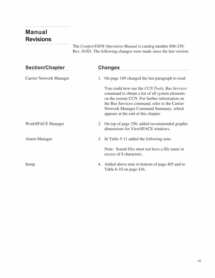
The ComfortVIEW Operation Manual is catalog number 808-239,Rev. 01/03. The following changes were made since the last version:
Section/Chapter Changes
Carrier Network Manager 1. On page 169 changed the last paragraph to read:
You could now use the CCN Tools, Bus Servicescommand to obtain a list of all system elementson the remote CCN. For further information onthe Bus Services command, refer to the CarrierNetwork Manager Command Summary, whichappears at the end of this chapter.
WorkSPACE Manager 2. On top of page 256, added recommended graphicdimensions for ViewSPACE windows.
Alarm Manager 3. In Table 5-11 added the following note:
Note: Sound files must not have a file name inexcess of 8 characters.
Setup 4. Added above note to bottom of page 405 and toTable 6-10 on page 416.
Manual
Revisions
vii

viii

Introduction

Alarm Manager
1
ComfortVIEW ™ is the Carrier Corporation software that is theprimary man/machine interface to the Carrier Comfort Network(CCN). The software, designed to run under the Microsoft® Win-dows® 2000 or Windows XP Professional operating system, enablesyou to quickly identify information and intuitively perform alloperator functions.
ComfortVIEW provides the tools you need for monitoring, config-uring, and analyzing your facility’s daily HVAC operations. Youcan achieve optimum results using the following ComfortVIEWfeatures and functions:
• WorkSPACE Manager Application — You can create customizeddisplays of data that you care about most and save them asWorkSPACEs. Each WorkSPACE can consist of multiple graphicdisplays of any type of data, including trending information.
• Dynamic Trending — You can elect to trend any availablerealtime data point, and store report output in a format compat-ible with spreadsheet industry standards.
• Simultaneous Dynamic Displays — You can simultaneouslydisplay data from multiple controllers — either controllerslocated in the same area or, using concurrent modem connec-tions, data from controllers at remote areas.
• Fast Alarm Response — You can see and acknowledge incom-ing alarms, regardless of the application that you have runningon your computer. With the click of the mouse, you can jump tothe WorkSPACE that is pertinent to the given alarm condition.You can record the action you have taken in response to analarm by attaching a note to the alarm entry. You can suppressthe annunciation of specified alarm conditions to avoid interrup-tion by known “nuisance-type” alarms.
• Database — Depending on how you set up your ComfortVIEWsystem, your database can be shared by other ComfortVIEWoperators at other computers. Changes made by ComfortVIEWoperators are stored in a central area to create a common sourceof data.
• Logical Controller Groupings — You can group controllers intouser-defined buildings, floors, areas or regions, independent ofyour Carrier Comfort Network architecture.
Introduction
2
The ComfortVIEW Operation Manual is designed for use by indi-viduals who have completed CCN training and have a workingknowledge of Windows.
The manual is organized in a how-to functional format to help youreadily locate the information you need.
This manual contains the following chapters:
• Introduction• Carrier Network Manager• Remote Access• WorkSPACE Manager• Alarm Manager• Setup• Report Panel• Global Function Manager• Appendix A• Appendix B
The Introduction chapter consists of this description of the manual,login and logout instructions, and a description of ComfortVIEWwindow format, menus, and commands. The chapter also includesmouse and keyboard instructions, including an overview of the keysand mouse techniques that you will typically use in operatingComfortVIEW.
The Carrier Network Manager chapter provides instructions onadding ComfortVIEW operators, specifying alarm printers, connect-ing to remote CCNs and remote ComfortVIEW computers, andadding, viewing, and modifying controller data.
The Remote Access chapter provides instructions for connecting toand disconnecting from a remote ComfortVIEW server.
The WorkSPACE Manager chapter provides instructions on creatingcustomized displays of data that you care about most and savingthem as WorkSPACEs, which are multiple graphic and tabular
About this Manual
Intended Audience
Description ofChapters

3
displays of any type of data, including trending information.
The Alarm Manager chapter provides instructions on usingComfortVIEW alarm indication and alarm handling capabilities.
The Setup chapter provides information on defining local areanetwork workstations and alarm printers. It also includes instructionson specifying global system parameters such as time of day forautomatic report data retrieval, and the time period for retainingreport data in your ComfortVIEW database.
The Report Panel chapter provides instructions on generating con-sumable, runtime, and history reports to view, print, export, or saveon ComfortVIEW hard disk. Refer to the end of the Report Panelchapter for samples of ComfortVIEW reports.
The Global Function Manager chapter provides instructions onconfiguring ComfortVIEW to automatically force and auto groups ofpoints, perform point data transfers onto the CCN Bus, create centraloccupancy schedules, and configure global holidays.
Appendix A provides instructions on generating additionalComfortVIEW reports. Current additional reports include the Sys-tem Activity, Alarm Summary, Time Schedule, Tenant BillingSummary, and Tenant Billing Activity report.
Appendix B describes the CCN time and setpoint schedule, globaloccupancy schedule, and remote site connection DLL that is in-cluded with the standard ComfortVIEW installation.
Instructions Assume: All step-by-step instructions assume that eachComfortVIEW application is either inactive or minimized. Theinstructions begin by instructing you to double click on an icon tolaunch the application. For example, in Viewing the Alarm List,which appears in the Alarms chapter, the first step tells you todouble click on the Alarm Manager icon. If, however, the AlarmManager application is active, but hidden by another window, pressAlt, and with this key held down, repeatedly press the Tab key toswitch through all active applications until the Alarm Managerdisplays on your window.
Standards UsedThroughout thisManual
4
Using the Mouse: The instructions in this manual assume you areusing a mouse to operate your ComfortVIEW. For keyboard instruc-tions, refer to Using the Keyboard, which appears under UsingComfortVIEW: An Overview, and To Select a Command UsingYour Keyboard, which appears under ComfortVIEW Menus andCommands Lists.
Icon Illustrations: To help you locate and identify the variousComfortVIEW icons, the manual includes an illustration of eachicon in the left margin next to the instructions describing the icon’suse. Each chapter also includes a table displaying and describingeach of the icons in the toolbar.
Menu Commands: To help you locate a description of each menubar command, the last section of each chapter contains a commandsummary.
Dialog Boxes: All ComfortVIEW applications use dialog boxes,which are special windows containing options that you select tospecify how ComfortVIEW should carry out a command. Thenumbered-step instructions that appear throughout this manual donot explain all dialog box options available to you. You can, how-ever, find full summaries of all dialog box options in the tables thatimmediately follow the numbered steps. You can also access thesetables while using ComfortVIEW by clicking on Help while display-ing a dialog box. Thus, while performing some of the instructions inthis manual, you may need to refer out of the numbered steps tothese tables.
The sample instructions below illustrate the use of numbered stepsand tables to explain dialog box options.
5
1. Select the alarms to which you wish to attach a note byfollowing the instructions found under Selecting Alarms.
2. Click on the Functions menu item and then click on Note.
ComfortVIEW displays the Operator Note dialog box.
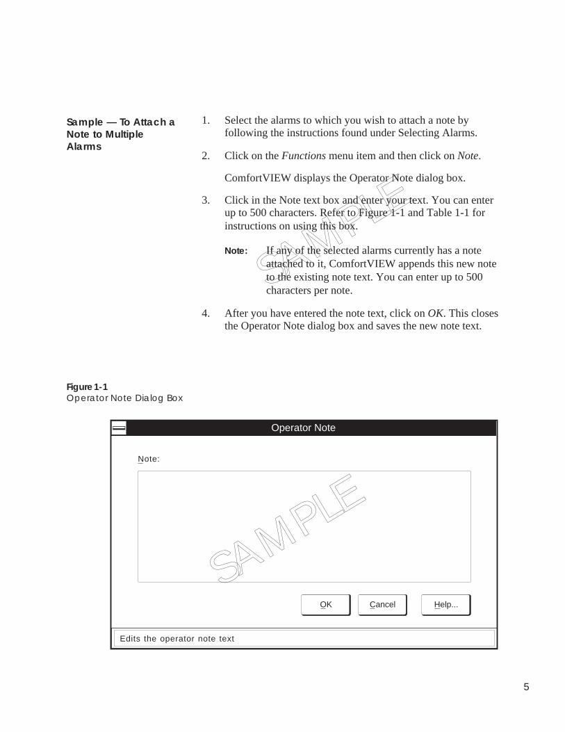
3. Click in the Note text box and enter your text. You can enterup to 500 characters. Refer to Figure 1-1 and Table 1-1 forinstructions on using this box.
Note: If any of the selected alarms currently has a noteattached to it, ComfortVIEW appends this new noteto the existing note text. You can enter up to 500characters per note.
4. After you have entered the note text, click on OK. This closesthe Operator Note dialog box and saves the new note text.
Sample — To Attach aNote to MultipleAlarms
Figure 1-1Operator Note Dialog Box
Operator Note
OK Cancel Help...
Note:
Edits the operator note text
SAMPLE
SAMPLE
6
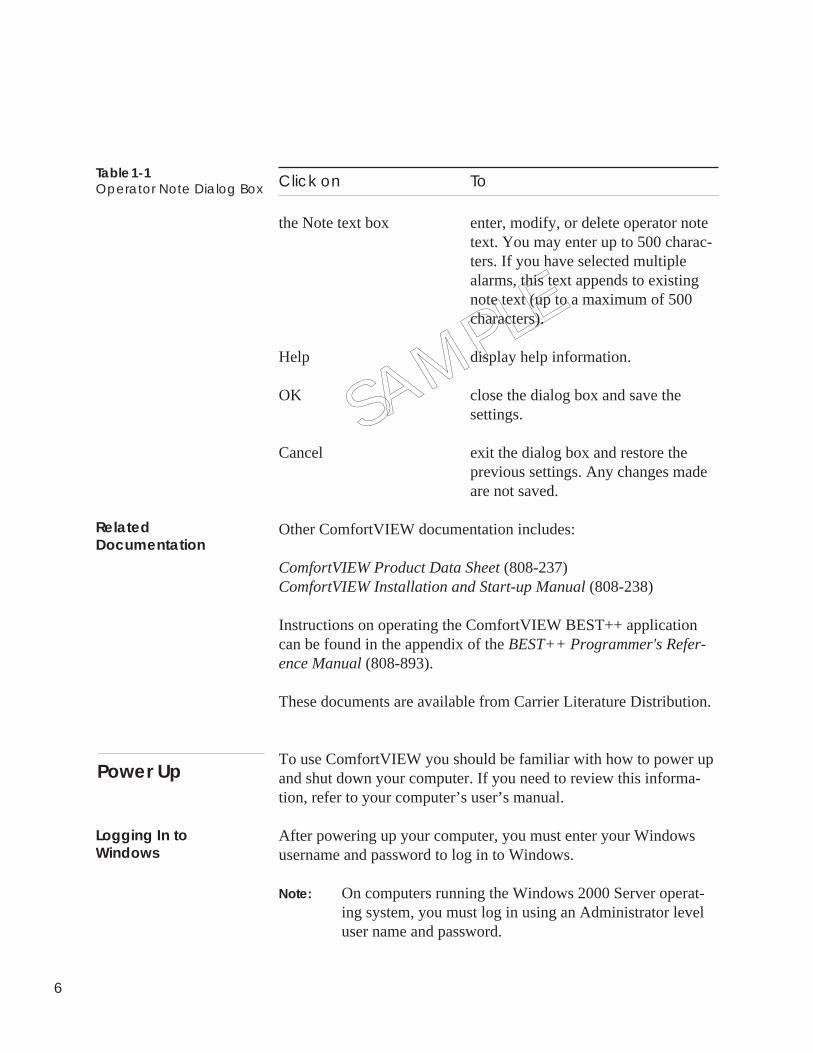
Click on To
the Note text box enter, modify, or delete operator notetext. You may enter up to 500 charac-ters. If you have selected multiplealarms, this text appends to existingnote text (up to a maximum of 500characters).
Help display help information.
OK close the dialog box and save thesettings.
Cancel exit the dialog box and restore theprevious settings. Any changes madeare not saved.
Other ComfortVIEW documentation includes:
ComfortVIEW Product Data Sheet (808-237)ComfortVIEW Installation and Start-up Manual (808-238)
Instructions on operating the ComfortVIEW BEST++ applicationcan be found in the appendix of the BEST++ Programmer's Refer-ence Manual (808-893).
These documents are available from Carrier Literature Distribution.
To use ComfortVIEW you should be familiar with how to power upand shut down your computer. If you need to review this informa-tion, refer to your computer’s user’s manual.
After powering up your computer, you must enter your Windowsusername and password to log in to Windows.
Note: On computers running the Windows 2000 Server operat-ing system, you must log in using an Administrator leveluser name and password.
SAMPLE
Table 1-1Operator Note Dialog Box
RelatedDocumentation
Logging In toWindows
Power Up
7
Next, you must log in to ComfortVIEW. Follow the ComfortVIEWLogging In instructions that appear on the pages which follow.
Note: If the Auto-Login feature has been enabled for thisComfortVIEW workstation, you will be automaticallylogged into ComfortVIEW as part of Windows login. TheComfortVIEW Logout application will display in theWindows taskbar, which is typically located at the bottomof your screen. For more information on this Auto-Loginfeature, refer to Specifying Global System Parameters inthe Setup chapter of this manual.
For Windows 2000:
1. Click on the Windows Start button and then click on ShutDown.
2. In the Shut Down Windows dialog box, select Log off (fol-lowed by your username).
3. Then, click on Yes.
For Windows XP:
1. Click on the Windows Start button and then click on Log Off.
2. In the Log Off Windows dialog box, click on Log Off.
After you log out of Windows, ComfortVIEW continues to run, andall network functions carry on. Report data is automatically re-trieved and alarms continue to be received from the network as theyoccur. Alarms will be indicated as configured.
ComfortVIEW applications are accessible to a single Windows XPuser account at a time - the first user to log in to Windows. If, onattempting to launch any ComfortVIEW application, you receive themessage ComfortVIEW is currently attached to another user ses-sion, this means that ComfortVIEW is currently running in anotherWindows XP user's session.
In order to run ComfortVIEW do the following:
Logging Out ofWindows
Windows XP and FastUser Switching
8
1. Log out of Windows XP.
2. Have the other ComfortVIEW user log out of bothComfortVIEW and Windows XP.
3. You can now log back in to Windows XP and will now bepermitted to log in to ComfortVIEW and run allComfortVIEW applications.
ComfortVIEW software is normally left running. Each time youbegin using ComfortVIEW, you must log in using the followingprocedure. This procedure can be ignored, however, if this worksta-tion has been configured for automatic ComfortVIEW login as partof Windows login.
Follow the steps below to log in to ComfortVIEW:
1. Log in to Windows.
Note: On computers running the Windows 2000 Serveroperating system, you must log in using an Admin-istrator level user name and password.
2. Double click on the ComfortVIEW Login icon which isshown at left.
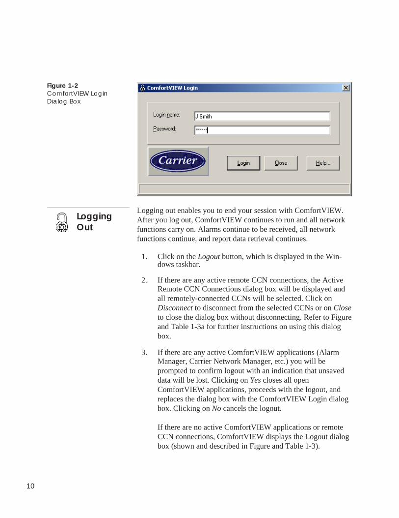
ComfortVIEW displays the ComfortVIEW Login dialog box(shown and described in Figure 1-2 and Table 1-2).
3. In the Login name text box, enter your login name.
Note: Passwords are case sensitive.
4. In the Password text box, enter your password.
ComfortVIEW displays your password as asterisks.
Logging In
Comfort WORKSLogin
9
5. Click on Login.
Note: If you enter an invalid username or password,ComfortVIEW displays an access denied message.Click on the OK button to close the message, thenrepeat Steps 3 and 4.
If you are successful in logging in, the message Logging in.Retrieving operator profile. displays in the dialog box.
6. When you have successfully logged in, the ComfortVIEWLogin dialog box closes and the ComfortVIEW Logoutapplication displays in the Windows taskbar, which is typi-cally located at the bottom of the screen. If you have selectedan application to automatically start up on login,ComfortVIEW opens this application. Refer to the Setting UpOperator Profiles Section of the Setup chapter of this manualfor instructions on configuring the Start-up applications.
Click on To
Login name text box enter your username. This name wasset by your ComfortVIEW systemadministrator during ComfortVIEWsoftware installation or when youwere added as an authorizedComfortVIEW operator. Theusername box displays the name of thelast ComfortVIEW operator whologged in.
Password text box enter your password. To protect yourpassword, only asterisks are displayedwhen you type. You must enter yourpassword using the correct case.ComfortVIEW distinguishes betweenupper and lower case letters.
Login log in using the username and pass-word entered.
Help display help information.
Cancel exit the dialog box without logging in.
Table 1-2ComfortVIEW LoginDialog Box
10
Figure 1-2ComfortVIEW LoginDialog Box
Logging out enables you to end your session with ComfortVIEW.After you log out, ComfortVIEW continues to run and all networkfunctions carry on. Alarms continue to be received, all networkfunctions continue, and report data retrieval continues.
1. Click on the Logout button, which is displayed in the Win-dows taskbar.
2. If there are any active remote CCN connections, the ActiveRemote CCN Connections dialog box will be displayed andall remotely-connected CCNs will be selected. Click onDisconnect to disconnect from the selected CCNs or on Closeto close the dialog box without disconnecting. Refer to Figureand Table 1-3a for further instructions on using this dialogbox.
3. If there are any active ComfortVIEW applications (AlarmManager, Carrier Network Manager, etc.) you will beprompted to confirm logout with an indication that unsaveddata will be lost. Clicking on Yes closes all openComfortVIEW applications, proceeds with the logout, andreplaces the dialog box with the ComfortVIEW Login dialogbox. Clicking on No cancels the logout.
If there are no active ComfortVIEW applications or remoteCCN connections, ComfortVIEW displays the Logout dialogbox (shown and described in Figure and Table 1-3).
LoggingOut
11
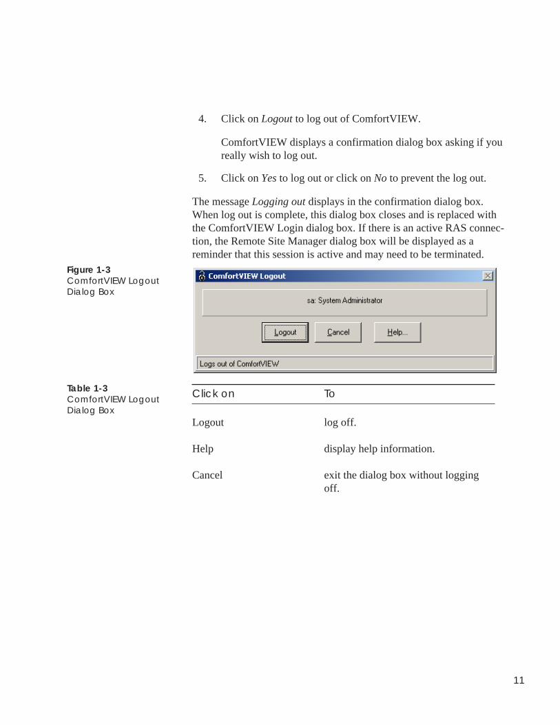
4. Click on Logout to log out of ComfortVIEW.
ComfortVIEW displays a confirmation dialog box asking if youreally wish to log out.
5. Click on Yes to log out or click on No to prevent the log out.
The message Logging out displays in the confirmation dialog box.When log out is complete, this dialog box closes and is replaced withthe ComfortVIEW Login dialog box. If there is an active RAS connec-tion, the Remote Site Manager dialog box will be displayed as areminder that this session is active and may need to be terminated.
Figure 1-3ComfortVIEW LogoutDialog Box
Click on To
Logout log off.
Help display help information.
Cancel exit the dialog box without loggingoff.
Table 1-3ComfortVIEW LogoutDialog Box
12
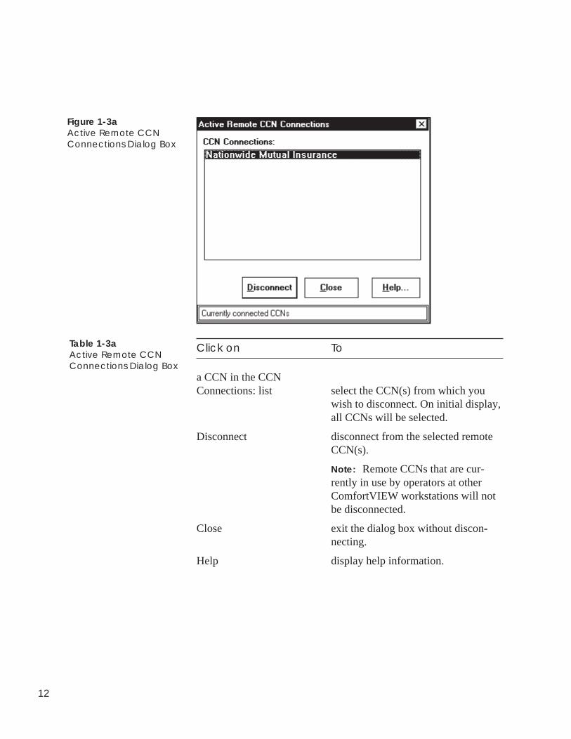
Figure 1-3aActive Remote CCNConnections Dialog Box
Click on To
a CCN in the CCNConnections: list select the CCN(s) from which you
wish to disconnect. On initial display,all CCNs will be selected.
Disconnect disconnect from the selected remoteCCN(s).
Note: Remote CCNs that are cur-rently in use by operators at otherComfortVIEW workstations will notbe disconnected.
Close exit the dialog box without discon-necting.
Help display help information.
Table 1-3aActive Remote CCNConnections Dialog Box
13
You can operate ComfortVIEW using your keyboard or your mouse.
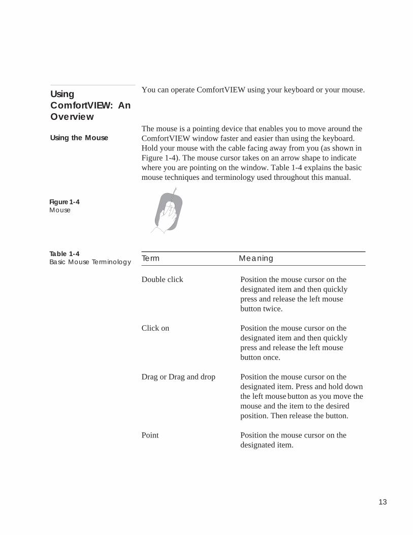
The mouse is a pointing device that enables you to move around theComfortVIEW window faster and easier than using the keyboard.Hold your mouse with the cable facing away from you (as shown inFigure 1-4). The mouse cursor takes on an arrow shape to indicatewhere you are pointing on the window. Table 1-4 explains the basicmouse techniques and terminology used throughout this manual.
Term Meaning
Double click Position the mouse cursor on thedesignated item and then quicklypress and release the left mousebutton twice.
Click on Position the mouse cursor on thedesignated item and then quicklypress and release the left mousebutton once.
Drag or Drag and drop Position the mouse cursor on thedesignated item. Press and hold downthe left mouse button as you move themouse and the item to the desiredposition. Then release the button.
Point Position the mouse cursor on thedesignated item.
Using the Mouse
UsingComfortVIEW: AnOverview
Figure 1-4Mouse
Table 1-4Basic Mouse Terminology
14
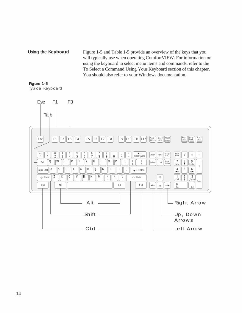
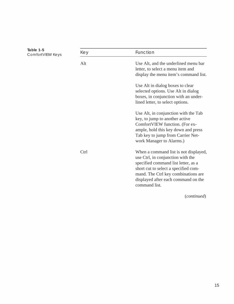
Figure 1-5 and Table 1-5 provide an overview of the keys that youwill typically use when operating ComfortVIEW. For information onusing the keyboard to select menu items and commands, refer to theTo Select a Command Using Your Keyboard section of this chapter.You should also refer to your Windows documentation.
Using the Keyboard
Figure 1-5Typical Keyboard
Esc F1 F2 F3 F4 F5 F6 F7 F8
1!
2@
3#
8*~
` 4$
5%
6^
7&
0)
-_
F9 F10 F11 F12
=+
Backspace
Tab
Caps Lock
Ctrl
Q W E R T Y U I O P
A S D F G H J K L
Z X C V B N M
Alt Alt Ctrl
Enter
{[
}]
|\
:;
"'
<,
?/
>.Shift Shift
Insert Home PageUp
PageDownEndDelete
Scrol lLock
PausePrintScreen
NumLock
CapsLock
ScrollLock
NumLock9
(
7 8 9
4 5 6
1 2 3
0Ins Del
EnterEnd
Home Pg Up
Pg Dn
/ *_
+
Break
Esc
Up, DownArrows
Left Arrow
Right Arrow
F3
Tab
Alt
Shift
Ctrl
F1
15
Key Function
Alt Use Alt, and the underlined menu barletter, to select a menu item anddisplay the menu item’s command list.
Use Alt in dialog boxes to clearselected options. Use Alt in dialogboxes, in conjunction with an under-lined letter, to select options.
Use Alt, in conjunction with the Tabkey, to jump to another activeComfortVIEW function. (For ex-ample, hold this key down and pressTab key to jump from Carrier Net-work Manager to Alarms.)
Ctrl When a command list is not displayed,use Ctrl, in conjunction with thespecified command list letter, as ashort cut to select a specified com-mand. The Ctrl key combinations aredisplayed after each command on thecommand list.
(continued)
Table 1-5ComfortVIEW Keys
16
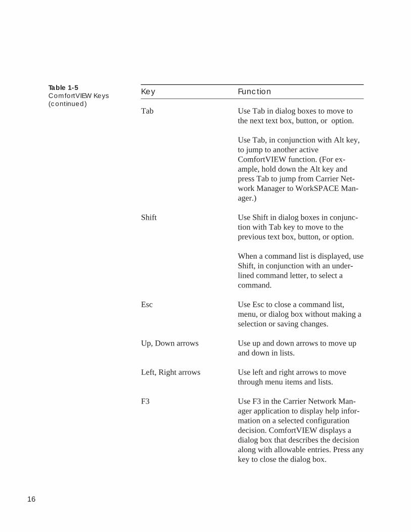
Key Function
Tab Use Tab in dialog boxes to move tothe next text box, button, or option.
Use Tab, in conjunction with Alt key,to jump to another activeComfortVIEW function. (For ex-ample, hold down the Alt key andpress Tab to jump from Carrier Net-work Manager to WorkSPACE Man-ager.)
Shift Use Shift in dialog boxes in conjunc-tion with Tab key to move to theprevious text box, button, or option.
When a command list is displayed, useShift, in conjunction with an under-lined command letter, to select acommand.
Esc Use Esc to close a command list,menu, or dialog box without making aselection or saving changes.
Up, Down arrows Use up and down arrows to move upand down in lists.
Left, Right arrows Use left and right arrows to movethrough menu items and lists.
F3 Use F3 in the Carrier Network Man-ager application to display help infor-mation on a selected configurationdecision. ComfortVIEW displays adialog box that describes the decisionalong with allowable entries. Press anykey to close the dialog box.
Table 1-5ComfortVIEW Keys(continued)

17
Key Function
F1 Use F1 to display help informationabout ComfortVIEW operation.
Table 1-5ComfortVIEW Keys(continued)

18
ComfortVIEW windows use a standard Windows format. Figure 1-6shows an example of a typical window. Table 1-6 describes thelabelled parts.
Figure 1-6ComfortVIEW Window
InterpretingComfortVIEWWindows
T i tle Bar MinimizeButton Maximize
Button
MenuBar
ScrollBar
WindowCorner(Drag
toresize)
Toolbar
AdministrationCarrier Network Manager - [United Mutual Farmington Office...39N...BASE UNIT: Sta
File Edit Configure Options HelpWindow
Description Value Units Status Force Name Notes
Space Temperature 74.0 degF SPT
Air Supply Temperature 57.3 degF SAT
Return Air Temperature 74.1 RAT
Outside Air Temperature 71.3 OAT
Static Pressure 1.3 SP
Relative Humidity 36.1 RH
Outside Air Rel Humidity 43.5 OARH
Freeze Status Normal FRZ
Filter Status Clean Alarm FLTS
Enthalpy Switch Low ENT
Supply Fan Status On SFS
Supply Fan Relay On SF
Heat Interlock Relay Off HIR
Inlet Guide Vanes 36.0 IGV
Mixed Air Damper 25.2 Alarm MIXD
Heating Coil Valve 100.0 HCV
Cooling Coil Valve 100.0 CCV
70.0
Control MenuBox
degF
degF
%%
%%%%
"H2O
Located in Room A101
0=closed, 100=open
0=closed, 100=open
0=closed, 100=open
0=closed, 100=open
CloseButton
19
Table 1-6ComfortVIEW WindowElements
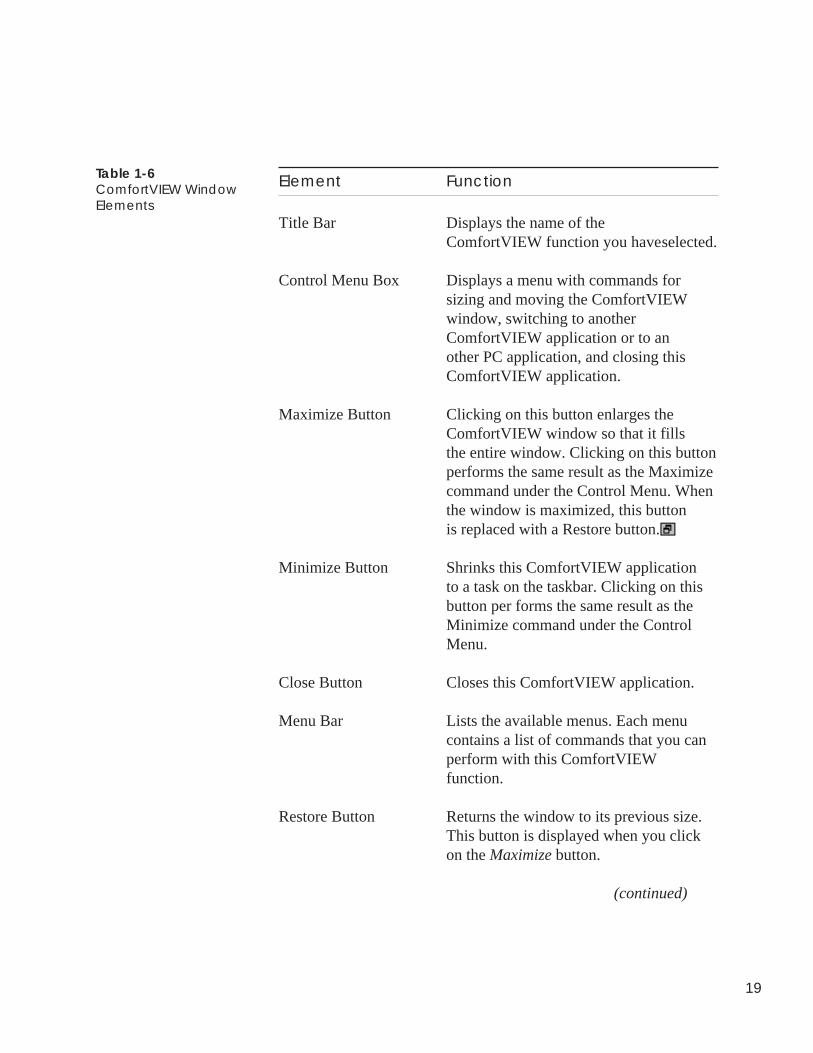
Element Function
Title Bar Displays the name of theComfortVIEW function you haveselected.
Control Menu Box Displays a menu with commands forsizing and moving the ComfortVIEWwindow, switching to anotherComfortVIEW application or to another PC application, and closing thisComfortVIEW application.
Maximize Button Clicking on this button enlarges theComfortVIEW window so that it fillsthe entire window. Clicking on this buttonperforms the same result as the Maximizecommand under the Control Menu. Whenthe window is maximized, this buttonis replaced with a Restore button.
Minimize Button Shrinks this ComfortVIEW applicationto a task on the taskbar. Clicking on thisbutton per forms the same result as theMinimize command under the ControlMenu.
Close Button Closes this ComfortVIEW application.
Menu Bar Lists the available menus. Each menucontains a list of commands that you canperform with this ComfortVIEWfunction.
Restore Button Returns the window to its previous size.This button is displayed when you clickon the Maximize button.
(continued)
20
Table 1-6ComfortVIEW WindowElements(continued)
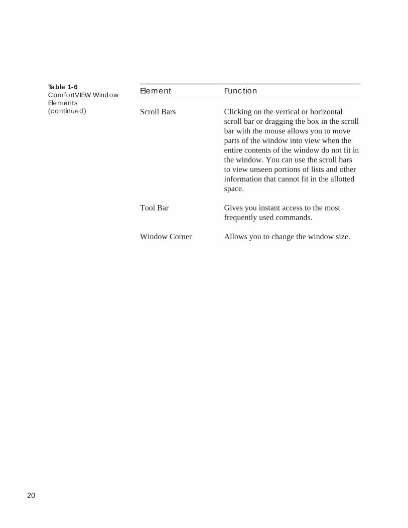
Element Function
Scroll Bars Clicking on the vertical or horizontalscroll bar or dragging the box in the scrollbar with the mouse allows you to moveparts of the window into view when theentire contents of the window do not fit inthe window. You can use the scroll barsto view unseen portions of lists and otherinformation that cannot fit in the allottedspace.
Tool Bar Gives you instant access to the mostfrequently used commands.
Window Corner Allows you to change the window size.
21
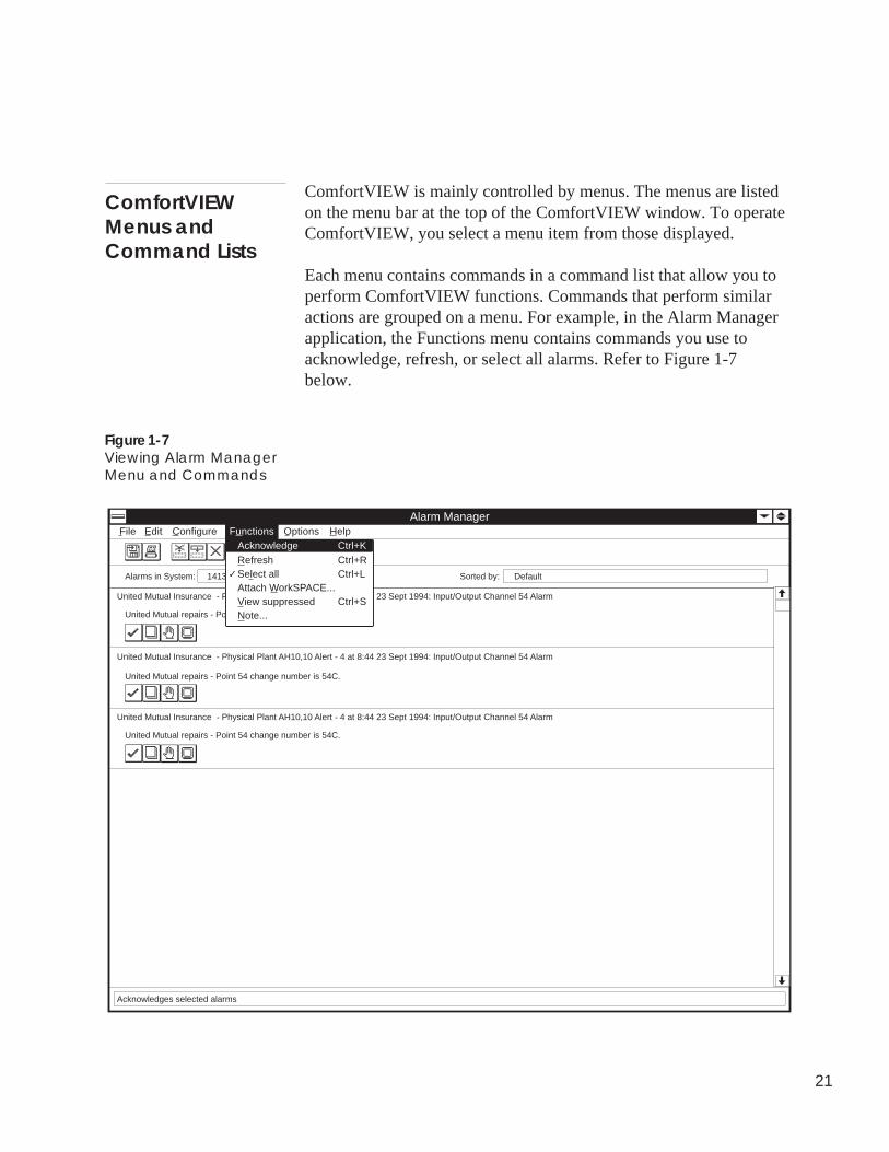
ComfortVIEW is mainly controlled by menus. The menus are listedon the menu bar at the top of the ComfortVIEW window. To operateComfortVIEW, you select a menu item from those displayed.
Each menu contains commands in a command list that allow you toperform ComfortVIEW functions. Commands that perform similaractions are grouped on a menu. For example, in the Alarm Managerapplication, the Functions menu contains commands you use toacknowledge, refresh, or select all alarms. Refer to Figure 1-7below.
ComfortVIEWMenus andCommand Lists
Figure 1-7Viewing Alarm ManagerMenu and Commands
Alarms in System: 1413 Alarms in viewing buffer:
United Mutual Insurance - Physical Plant AH10,10 Alert - 4 at 8:44 23 Sept 1994: Input/Output Channel 54 Alarm
United Mutual repairs - Point 54 change number is 54C.
Alarm Manager
Sorted by: Default
United Mutual Insurance - Physical Plant AH10,10 Alert - 4 at 8:44 23 Sept 1994: Input/Output Channel 54 Alarm
United Mutual Insurance - Physical Plant AH10,10 Alert - 4 at 8:44 23 Sept 1994: Input/Output Channel 54 Alarm
File Edit Configure Options Help
United Mutual repairs - Point 54 change number is 54C.
United Mutual repairs - Point 54 change number is 54C.
Acknowledges selected alarms
FunctionsAcknowledgeRefresh
Ctrl+K
Select allAttach WorkSPACE...View suppressedNote...
Ctrl+RCtrl+L
Ctrl+S
✓
22
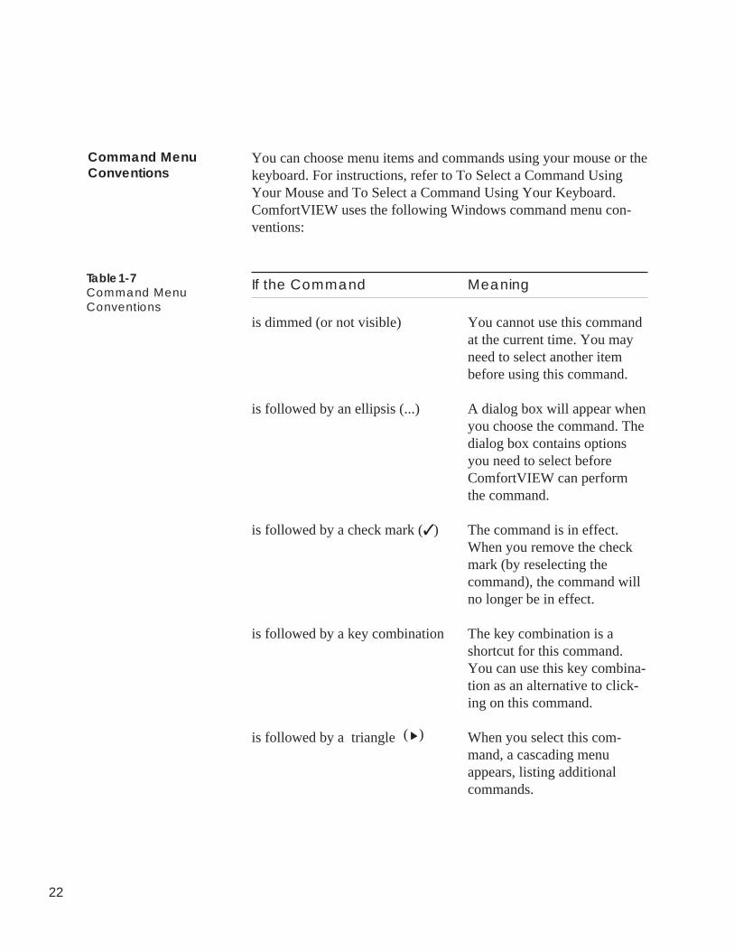
You can choose menu items and commands using your mouse or thekeyboard. For instructions, refer to To Select a Command UsingYour Mouse and To Select a Command Using Your Keyboard.ComfortVIEW uses the following Windows command menu con-ventions:
If the Command Meaning
is dimmed (or not visible) You cannot use this commandat the current time. You mayneed to select another itembefore using this command.
is followed by an ellipsis (...) A dialog box will appear whenyou choose the command. Thedialog box contains optionsyou need to select beforeComfortVIEW can performthe command.
is followed by a check mark (✓ ) The command is in effect.When you remove the checkmark (by reselecting thecommand), the command willno longer be in effect.
is followed by a key combination The key combination is ashortcut for this command.You can use this key combina-tion as an alternative to click-ing on this command.
is followed by a triangle When you select this com-mand, a cascading menuappears, listing additionalcommands.
Table 1-7Command MenuConventions
Command MenuConventions
( )
23
1. Point to the menu item and click the left mouse button.
ComfortVIEW displays the list of commands for this menuitem.
Note: If you wish to close the menu without performingany command, click anywhere outside the menu.
2. Point to a command name and click the left mouse button.
ComfortVIEW carries out some commands right away. If anellipsis follows the command, however, more information isneeded to complete the command and a dialog box displays.You must then select options in the dialog box to control howComfortVIEW performs the command.
1. Press the Alt key and then release. Then, type the underlinedletter in the menu item name.
ComfortVIEW displays the list of commands for this menuitem.
Note: If you wish to close the menu without performingany command, press Esc.
2. Type the underlined letter in the command name.
ComfortVIEW carries out some commands right away. If anellipsis follows the command, however, more information isneeded to complete the command and a dialog box displays.You select options in the dialog box to control howComfortVIEW performs the command.
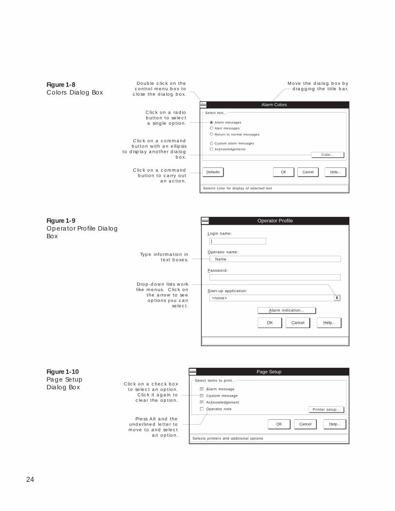
A dialog box is a special window containing options that you selectto tell ComfortVIEW how to carry out a command. The dialogboxes displayed in Figures 1-8, 1-9, and 1-10 illustrate some fea-tures common to all ComfortVIEW dialog boxes.
To Select a CommandUsing Your Mouse
To Select a CommandUsing Your Keyboard
Dialog Boxes
24
Figure 1-8Colors Dialog Box
Figure 1-9Operator Profile DialogBox
Figure 1-10Page SetupDialog Box
Acknowledgements
Custom alarm messages
Return to normal messages
Alarm messages
Alert messages
Alarm Colors
Select text...
Selects color for display of selected text
OK Cancel Help...Defaults
Color...
Move the dialog box bydragging the title bar.
Double click on thecontrol menu box to
close the dialog box.
Click on a radiobutton to selecta single option.
Click on a commandbutton to carry out
an action.
Click on a commandbutton with an ellipsis
to display another dialogbox.
Login name:
Operator Profile
OK Cancel Help...
Start-up application:
<none>
Alarm indication...
Password:
Operator name:
Name
Drop-down lists worklike menus. Click on
the arrow to seeoptions you can
select.
Type information intext boxes.
Press Alt and theunderlined letter tomove to and select
an option.
Click on a check boxto select an option.
Click it again toclear the option.
Printer setup...
Page Setup
Select items to print...
OK Cancel Help...
Selects printers and additional options
Alarm message
X
Custom message
X
Acknowledgement
X
Operator note
25
Help information is available throughout ComfortVIEW. Here arethe ways you can access help:
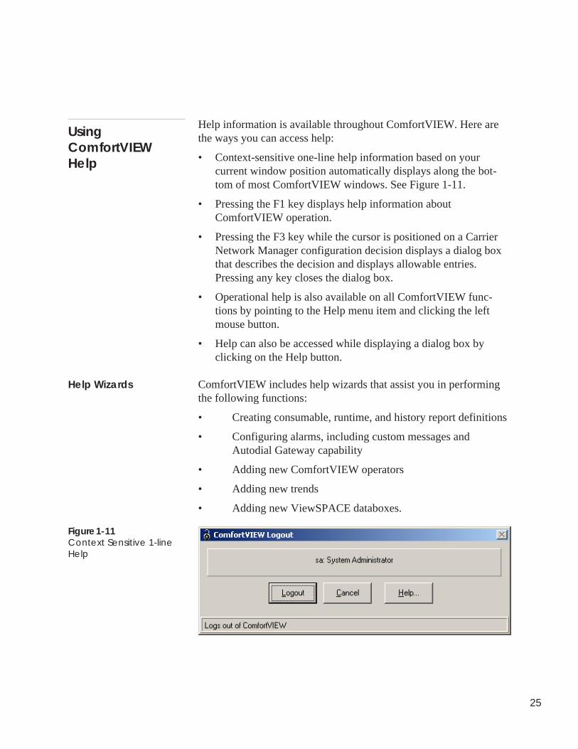
• Context-sensitive one-line help information based on yourcurrent window position automatically displays along the bot-tom of most ComfortVIEW windows. See Figure 1-11.
• Pressing the F1 key displays help information aboutComfortVIEW operation.
• Pressing the F3 key while the cursor is positioned on a CarrierNetwork Manager configuration decision displays a dialog boxthat describes the decision and displays allowable entries.Pressing any key closes the dialog box.
• Operational help is also available on all ComfortVIEW func-tions by pointing to the Help menu item and clicking the leftmouse button.
• Help can also be accessed while displaying a dialog box byclicking on the Help button.
ComfortVIEW includes help wizards that assist you in performingthe following functions:
• Creating consumable, runtime, and history report definitions
• Configuring alarms, including custom messages andAutodial Gateway capability
• Adding new ComfortVIEW operators
• Adding new trends
• Adding new ViewSPACE databoxes.
UsingComfortVIEWHelp
Help Wizards
Figure 1-11Context Sensitive 1-lineHelp

26

Carrier NetworkManager

Alarm Manager
27
CarrierNetworkManager
This chapter provides instructions on ComfortVIEW Carrier Net-work Manager application.
For instructions on... Turn to page
launching the Carrier Network Managerapplication and displaying the SystemOverview and Controller List windows 32
changing the font and point size of CarrierNetwork Manager text 38
adding and configuring CCNs and areas:• adding a new or modifying an existing CCN 39• adding a new or modifying an existing area 54• deleting CCNs and areas 56
adding controllers:• displaying the controller list 58• sorting the controller list 59• adding/modifying controllers 60
deleting controllers 69
viewing controller data:• viewing status display and maintenance tables 70• viewing configuration tables 78• viewing alarm history tables 81
performing Bus Services functions:• polling the CCN Bus and updating the
NDS Module (Update Poll) 82, 184• obtaining a list of system elements on a
CCN (Cold Call) 82
28
For instructions on... Turn to page
modifying controller data:• forcing/autoing status display and maintenance
tables 92• modifying configuration table values and using drag
and drop 97• modifying controller table names and descriptions 104• copying and moving controller configuration data 107• verifying controller configuration against your
database 114• downloading ComfortVIEW data to controllers 115• uploading controller data to ComfortVIEW 116• modifying and sending time and date 118• displaying and configuring CCN Options 120• configuring UT203 FIDs 128• configuring Comfort Controllers 132
exporting controller databases 163importing controller databases 179
connecting to remote CCNs:• reserving Autodial Gateways for specific
operations 166• using an Autodial Gateway 169• disconnecting from remote CCNs 170
printing Carrier Network Manager data 171
using ComfortVIEW data in other PC applications 175
a summary of all Carrier Network Manager commands 179
29
The following terms are used throughout this Carrier NetworkManager chapter.
Access Level — An operator privilege level. ComfortVIEW givesyou the capability to create access levels and specify specificComfortVIEW operations allowed for each level. You then assignaccess levels to ComfortVIEW operators on an area by area basis.
Access Parameters — How the new CCN will be accessed (physi-cally wired to ComfortVIEW workstation or via an Autodial Gate-way).
Active — Currently displayed on-screen or reduced to an icon.
Address — A unique two-part identification number for eachsystem element on the CCN. Address consists of the communicationbus number followed by the system element number.
Alarm Filters — ComfortVIEW gives you the capability to routealarms to specific ComfortVIEW operators. You set up alarm filtersthat specify families (area, element, and level) of alarms to bepresented to each ComfortVIEW operator. You then assign alarmfilters to ComfortVIEW operators. You can assign alarm filters toComfortVIEW operators on an area by area basis. You can also usealarm filters to route ComfortVIEW alarms to specific printers.
Alarm Table — Any of the Comfort Controller's standard alarmingroutines. Current Comfort Controller alarm tables include the Limit,Setpoint, Limit, Discrete State, First Out, Runtime, and Number ofStarts.
Algorithm — Any of the Comfort Controller's standard HVACcontrol routines.
Area — A logical grouping of system elements within a CCN. Forexample, an area could be a building, a floor, a wing, or a chillerplant.
Autoing a point — To remove a force and return a point to thecontroller’s automatic control.
CCN — Carrier Comfort Network. A system of communicating,microprocessor-based controls for heating, ventilating and cooling(HVAC) equipment.
Terminology
30
Client — A computer on a local area network runningComfortVIEW communication and user interface software, orComfortVIEW user interface software only.
Configure — To specify to a controller the data that it needs tocontrol and monitor HVAC devices in the desired manner.
Controllers — CCN system elements with addresses, status dis-play, and configuration tables. Controllers perform the actualHVAC monitoring and control operations. The Carrier ComfortNetwork supports several types of controllers. These include PICs,FIDs, and Comfort Controllers, System Managers, and CCN Op-tions.
Controller — A CCN system element with an address, statusdisplay, and configuration tables. A controller performs the actualHVAC monitoring and control operations. The Carrier ComfortNetwork supports several types of controllers. These include PICs,FIDs, and Comfort Controllers, System Managers (examples: TSM,FSM, CSM), and CCN Options.
Destination — The configuration table you are copying to whencopying and moving controller configuration data.
Download — To copy configuration table data from theComfortVIEW database to a controller. Performing a downloadoverwrites the configuration at the controller.
Export — To back up an entire controller's database to a specifieddrive. The drive can be the ComfortVIEW floppy diskette drive,another ComfortVIEW hard drive partition, or another computer onthe LAN. The information that will be copied includes the controllername, description, address, and all configuration data.
Force — To override a controller’s automatic control and modify apoint’s value.
Function — Any of the Comfort Controller's supporting controlroutines for points and algorithms. Current Comfort Controllerfunction tables include Analog Trace Point, Discrete Trace Point,Internal Consumable, Adaptive Optimal Start/Stop, Network Broad-cast, Linkage/AOSS Schedule, Night Time Free Cooling, andOccupancy.
31
Gateway — Refers to either a CCN Autodial Gateway or TeLINKmodule. Both these modules enable the CCN to communicate overtelephone lines with other similarly equipped CCNs enabling systemelements in two networks to communicate as though they wereconnected directly.
Import — To copy configuration tables to a controller in theComfortVIEW database from a .CWX file that was created usingComfortVIEW Export function.
Operators — ComfortVIEW users.
Object — A Comfort Controller hardware or software point, systemtable, algorithm, setpoint, alarm, or function.
Point — An input or output (hardware) channel on the controller oran internal (software) channel.
Server — A computer running ComfortVIEW communication, userinterface, service, and database software.
Sort key — Numbers, assigned when adding controllers to thedatabase, that give you the capability to customize the presentationof your controller list. In a controller list that is sorted by sort key, acontroller assigned a sort key of 1 appears before a controller as-signed a sort key of 2, and so on. Assigning a controller a sort keyof 255 causes it to appear at the end of the controller list. Thedefault sort key number is 1.
Source — The point status, maintenance, or time schedule table youare copying from when copying and moving controller configura-tion data.
System Element — A CCN controller with an address and configu-ration tables. A controller performs the actual HVAC monitoringand control operations. The Carrier Comfort Network supportsseveral types of system elements. These include PICs, FIDs, andComfort Controllers, System Managers (examples: TSM, FSM,CSM), and CCN Options.
System Table — A Comfort Controller Consumable, Runtime,Holiday, Network Time Schedule, Loadshed, or Language Conver-sion table.
32
Table — A logical grouping of data that a controller uses to displayand specify information used to control and monitor HVAC devicesin the desired manner. Examples of tables are status display tables,alarm history, configuration tables, and maintenance tables.
Upload — To copy all configuration table data from a controller tothe ComfortVIEW database.
The Carrier Network Manager graphically displays, through the useof a directory tree with a branching structure similar to the WindowsFile Manager, the CCNs, areas, controllers (system elements), andtables that make up your ComfortVIEW database.
You can use the Carrier Network Manager to add and configureCCNs and areas, which are logical groupings of system elementswithin a CCN (for example, buildings, floors, wings, chiller plants).
You can also perform other operations such as:
• adding controllers to and deleting controllers from yourComfortVIEW database.
• viewing and modifying controller configuration,maintenance, and status display data.
• exporting controller databases to diskette.
• connecting to remote CCNs and remote ComfortVIEWworkstations.
Follow the steps below to launch the Carrier Network Managerapplication, open the System Overview window, and display a listof the database’s CCNs and areas.
1. Double click on the Carrier Network Manager icon.
ComfortVIEW opens the Carrier Network Manager anddisplays a System Overview window (similar to the oneshown in Figure 2-1) This window displays, in a directorytree fashion, the CCNs that make up your ComfortVIEWdatabase.
Accessingthe Carrier
Network Manager
33
The top line of the window contains the menu bar. Refer tothe Carrier Network Manager Command Summary section ofthis chapter for a description of each menu bar command.The second line of the window contains the toolbar. Refer toCarrier Network Manager Toolbar, which appears later in thissection, for information on using each toolbar button.
The third line of the window contains the status bar. This linedisplays in all Carrier Network Manager windows and sup-plies information on the path you have taken to arrive at thecurrent window. (For example, it displays the CCN, area, andcontroller name that you have selected.)
Note: If desired, you can remove the status bar from theSystem Overview window by clicking on the Op-tions menu item followed by clicking on Status bar.To return the status bar to the window, performthese two commands again.
You may also change the window’s font and pointsize. Refer to the Changing the Font section of thischapter for instructions.
2. Double click on the System Overview icon to expand thedirectory tree and display the CCNs in your database.
Note: Double clicking on an expanded System Overviewicon collapses the tree.
3. Double click on a CCN to expand the directory tree anddisplay the areas in that CCN.
Note: If this is the first time you are accessing the CarrierNetwork Manager since installing ComfortVIEW,there will be no CCNs. Refer to Adding/ModifyingCCNs. Double clicking on an expanded CCNcollapses the tree.
Figure 2-1 shows an expanded System Overview window.Refer to Table 2-1 for an explanation of the System Overviewtree icons.
34
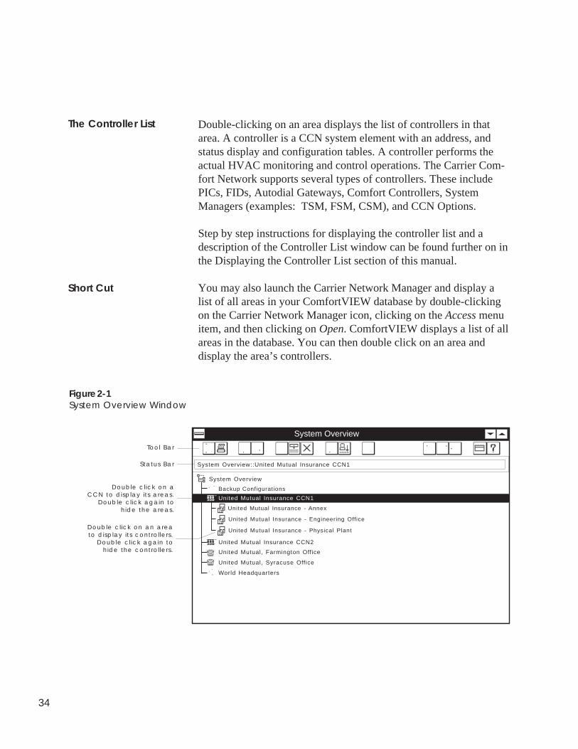
Double-clicking on an area displays the list of controllers in thatarea. A controller is a CCN system element with an address, andstatus display and configuration tables. A controller performs theactual HVAC monitoring and control operations. The Carrier Com-fort Network supports several types of controllers. These includePICs, FIDs, Autodial Gateways, Comfort Controllers, SystemManagers (examples: TSM, FSM, CSM), and CCN Options.
Step by step instructions for displaying the controller list and adescription of the Controller List window can be found further on inthe Displaying the Controller List section of this manual.
You may also launch the Carrier Network Manager and display alist of all areas in your ComfortVIEW database by double-clickingon the Carrier Network Manager icon, clicking on the Access menuitem, and then clicking on Open. ComfortVIEW displays a list of allareas in the database. You can then double click on an area anddisplay the area’s controllers.
The Controller List
Short Cut
Figure 2-1System Overview Window
Tool Bar
Double click on aCCN to display its areas.
Double click again tohide the areas.
System Overview
United Mutual Insurance CCN1
System Overview
System Overview::United Mutual Insurance CCN1Status Bar
Double click on an areato display its controllers.
Double click again to hide the controllers.
Backup Configurations
United Mutual Insurance - Annex
United Mutual Insurance - Engineering Office
United Mutual Insurance - Physical Plant
United Mutual Insurance CCN2
United Mutual, Farmington Office
United Mutual, Syracuse Office
World Headquarters
35
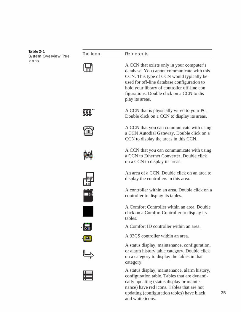
Table 2-1System Overview TreeIcons
The Icon Represents
A CCN that exists only in your computer’sdatabase. You cannot communicate with thisCCN. This type of CCN would typically beused for off-line database configuration tohold your library of controller off-line configurations. Double click on a CCN to display its areas.
A CCN that is physically wired to your PC.Double click on a CCN to display its areas.
A CCN that you can communicate with usinga CCN Autodial Gateway. Double click on aCCN to display the areas in this CCN.
A CCN that you can communicate with usinga CCN to Ethernet Converter. Double clickon a CCN to display its areas.
An area of a CCN. Double click on an area todisplay the controllers in this area.
A controller within an area. Double click on acontroller to display its tables.
A Comfort Controller within an area. Doubleclick on a Comfort Controller to display itstables.
A Comfort ID controller within an area.
A 33CS controller within an area.
A status display, maintenance, configuration,or alarm history table category. Double clickon a category to display the tables in thatcategory.
A status display, maintenance, alarm history,configuration table. Tables that are dynami-cally updating (status display or mainte-nance) have red icons. Tables that are notupdating (configuration tables) have blackand white icons.
36
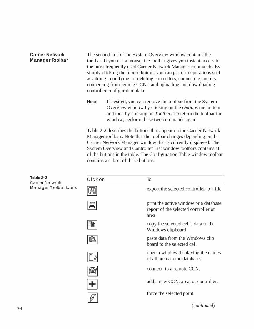
The second line of the System Overview window contains thetoolbar. If you use a mouse, the toolbar gives you instant access tothe most frequently used Carrier Network Manager commands. Bysimply clicking the mouse button, you can perform operations suchas adding, modifying, or deleting controllers, connecting and dis-connecting from remote CCNs, and uploading and downloadingcontroller configuration data.
Note: If desired, you can remove the toolbar from the SystemOverview window by clicking on the Options menu itemand then by clicking on Toolbar. To return the toolbar thewindow, perform these two commands again.
Table 2-2 describes the buttons that appear on the Carrier NetworkManager toolbars. Note that the toolbar changes depending on theCarrier Network Manager window that is currently displayed. TheSystem Overview and Controller List window toolbars contains allof the buttons in the table. The Configuration Table window toolbarcontains a subset of these buttons.
Click on To
export the selected controller to a file.
print the active window or a databasereport of the selected controller orarea.
copy the selected cell's data to theWindows clipboard.
paste data from the Windows clipboard to the selected cell.
open a window displaying the namesof all areas in the database.
connect to a remote CCN.
add a new CCN, area, or controller.
force the selected point.
(continued)
Carrier NetworkManager Toolbar
Table 2-2Carrier NetworkManager Toolbar Icons
37
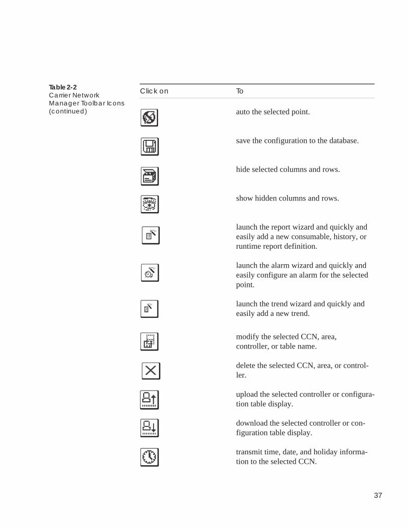
Click on To
auto the selected point.
save the configuration to the database.
hide selected columns and rows.
show hidden columns and rows.
launch the report wizard and quickly andeasily add a new consumable, history, orruntime report definition.
launch the alarm wizard and quickly andeasily configure an alarm for the selectedpoint.
launch the trend wizard and quickly andeasily add a new trend.
modify the selected CCN, area,controller, or table name.
delete the selected CCN, area, or control-ler.
upload the selected controller or configura-tion table display.
download the selected controller or con-figuration table display.
transmit time, date, and holiday informa-tion to the selected CCN.
Table 2-2Carrier NetworkManager Toolbar Icons(continued)
38
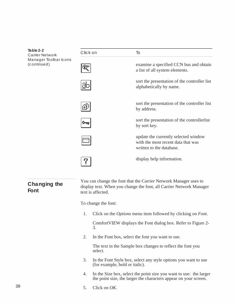
Click on To
examine a specified CCN bus and obtaina list of all system elements.
sort the presentation of the controller listalphabetically by name.
sort the presentation of the controller listby address.
sort the presentation of the controllerlistby sort key.
update the currently selected windowwith the most recent data that waswritten to the database.
display help information.
You can change the font that the Carrier Network Manager uses todisplay text. When you change the font, all Carrier Network Managertext is affected.
To change the font:
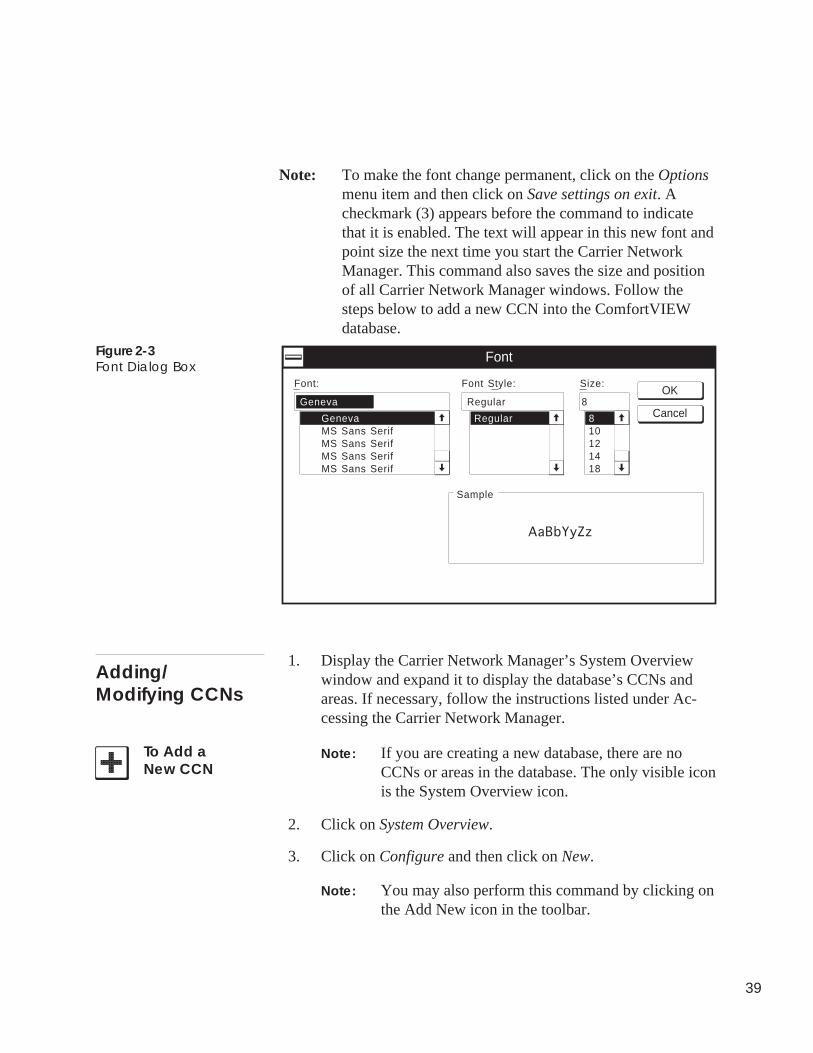
1. Click on the Options menu item followed by clicking on Font.
ComfortVIEW displays the Font dialog box. Refer to Figure 2-3.
2. In the Font box, select the font you want to use.
The text in the Sample box changes to reflect the font youselect.
3. In the Font Style box, select any style options you want to use(for example, bold or italic).
4. In the Size box, select the point size you want to use: the largerthe point size, the larger the characters appear on your screen.
5. Click on OK.
Table 2-2Carrier NetworkManager Toolbar Icons(continued)
Changing theFont
39
Note: To make the font change permanent, click on the Optionsmenu item and then click on Save settings on exit. Acheckmark (3) appears before the command to indicatethat it is enabled. The text will appear in this new font andpoint size the next time you start the Carrier NetworkManager. This command also saves the size and positionof all Carrier Network Manager windows. Follow thesteps below to add a new CCN into the ComfortVIEWdatabase.
Figure 2-3Font Dialog Box
8
8
Font:
Font
Sample
Font Style: Size:
GenevaMS Sans SerifMS Sans SerifMS Sans SerifMS Sans Serif
Regular
Regular10121418
AaBbYyZz
GenevaOK
Cancel
1. Display the Carrier Network Manager’s System Overviewwindow and expand it to display the database’s CCNs andareas. If necessary, follow the instructions listed under Ac-cessing the Carrier Network Manager.
Note: If you are creating a new database, there are noCCNs or areas in the database. The only visible iconis the System Overview icon.
2. Click on System Overview.
3. Click on Configure and then click on New.
Note: You may also perform this command by clicking onthe Add New icon in the toolbar.
Adding/Modifying CCNs
To Add aNew CCN
40
ComfortVIEW displays the Add New dialog box (shown inFigure 2-4 following these instructions). The Carrier ComfortNetwork (CCN) button will be selected.
4. Click on OK.
ComfortVIEW displays the New CCN Definition dialog box.
5. Enter the name of the new CCN in the CCN name edit box. Upto 48 characters are allowed.
6. You can modify the CCN Number if desired, or leave it set atthe displayed default value, which is the lowest available CCNnumber. This number is used internally by ComfortVIEWReport Panel and Alarm Manager applications to identifyCCNs. You must assign each CCN a unique number. UsedCCN numbers can be viewed by clicking on the down arrow inthe Used CCN number drop down list.
Note: If you are adding a remote CCN that will be accessedby Autodial Gateway, this number must match theCustomer Number configured at the remote AutodialGateway.
Refer to Figure 2-5 and Table 2-5 for instructions on using theNew CCN Definition dialog box.
7. Click on Access to display the CCN Access Definition dialogbox. This dialog box gives you the capability to specify accessparameters for the new CCN.
8. Click on the Method drop down list and select the way thisCCN will be accessed. Refer to Table 2-6 following theseinstructions for a definition of each CCN access method.
9. If you are adding a Local - Direct Connection CCN:
RS232/485: Click on the Port drop down list and select thecomputer serial port to which the CCN is attached.
CCN/Ethernet Gateway: Specify the IP address of this CCN'sCCN-to-Ethernet converter.
Then click on the Extended button to display the Standard CCNSettings dialog box and select additional CCN parameters such
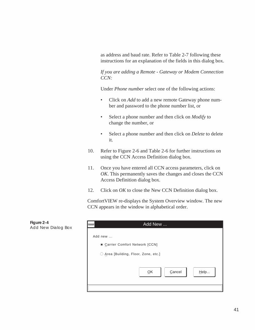
41
as address and baud rate. Refer to Table 2-7 following theseinstructions for an explanation of the fields in this dialog box.
If you are adding a Remote - Gateway or Modem ConnectionCCN:
Under Phone number select one of the following actions:
• Click on Add to add a new remote Gateway phone num-ber and password to the phone number list, or
• Select a phone number and then click on Modify tochange the number, or
• Select a phone number and then click on Delete to deleteit.
10. Refer to Figure 2-6 and Table 2-6 for further instructions onusing the CCN Access Definition dialog box.
11. Once you have entered all CCN access parameters, click onOK. This permanently saves the changes and closes the CCNAccess Definition dialog box.
12. Click on OK to close the New CCN Definition dialog box.
ComfortVIEW re-displays the System Overview window. The newCCN appears in the window in alphabetical order.
Figure 2-4Add New Dialog Box
Add New ...
Add new ...
Carrier Comfort Network [CCN]
Area [Building, Floor, Zone, etc.]
OK Cancel Help...
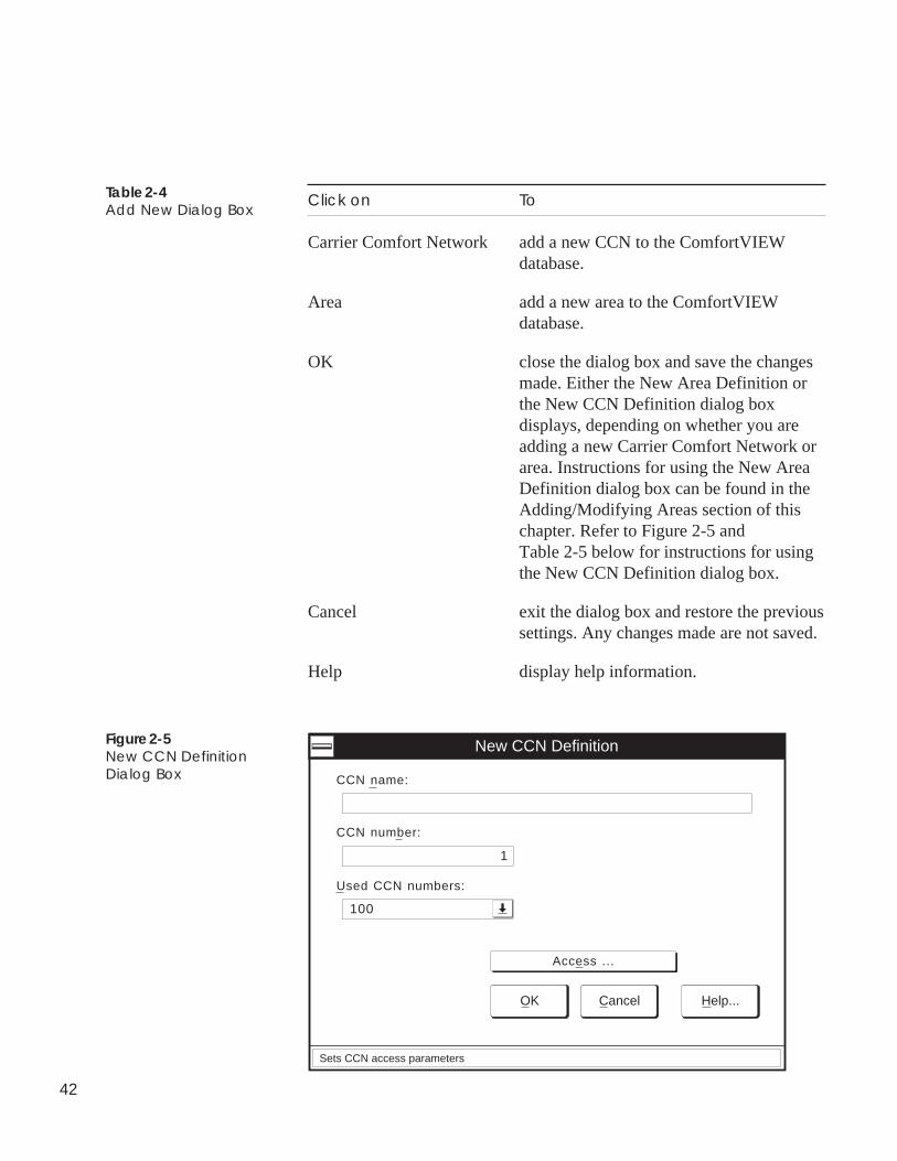
42
Click on To
Carrier Comfort Network add a new CCN to the ComfortVIEWdatabase.
Area add a new area to the ComfortVIEWdatabase.
OK close the dialog box and save the changesmade. Either the New Area Definition orthe New CCN Definition dialog boxdisplays, depending on whether you areadding a new Carrier Comfort Network orarea. Instructions for using the New AreaDefinition dialog box can be found in theAdding/Modifying Areas section of thischapter. Refer to Figure 2-5 andTable 2-5 below for instructions for usingthe New CCN Definition dialog box.
Cancel exit the dialog box and restore the previoussettings. Any changes made are not saved.
Help display help information.
Table 2-4Add New Dialog Box
Used CCN numbers:
New CCN Definition
CCN name:
OK Cancel Help...
100
Sets CCN access parameters
CCN number:
1
Access ...
Figure 2-5New CCN DefinitionDialog Box
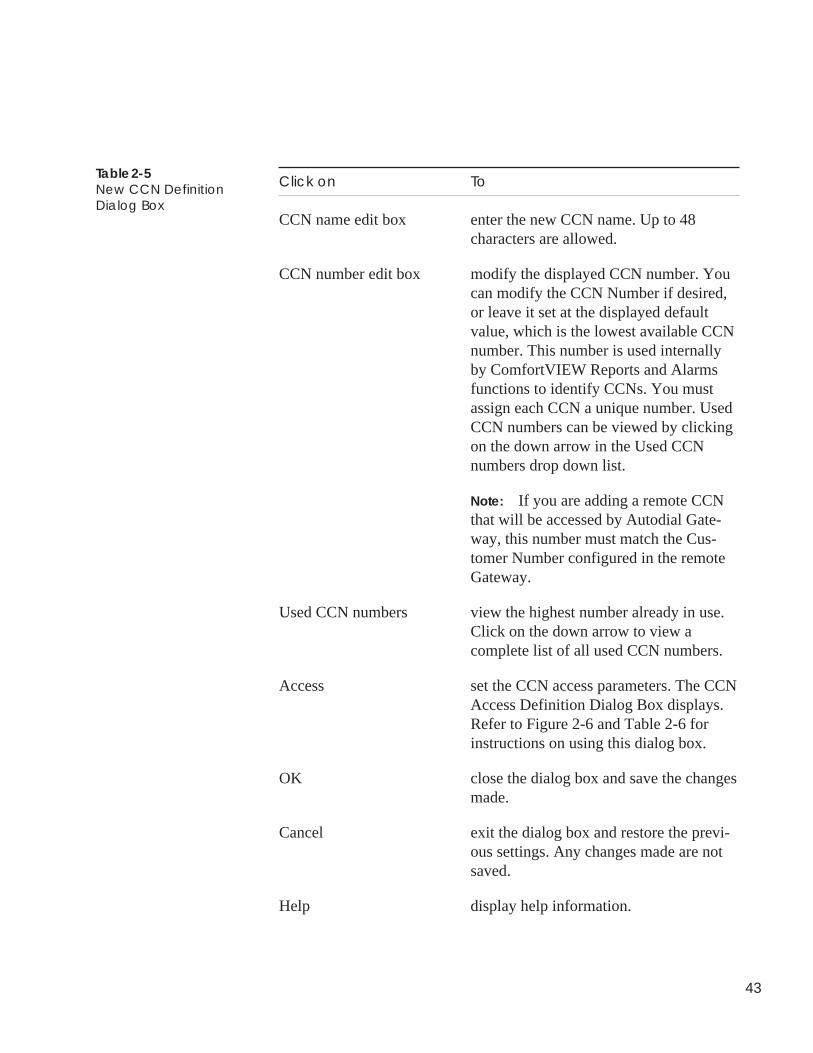
43
Click on To
CCN name edit box enter the new CCN name. Up to 48characters are allowed.
CCN number edit box modify the displayed CCN number. Youcan modify the CCN Number if desired,or leave it set at the displayed defaultvalue, which is the lowest available CCNnumber. This number is used internallyby ComfortVIEW Reports and Alarmsfunctions to identify CCNs. You mustassign each CCN a unique number. UsedCCN numbers can be viewed by clickingon the down arrow in the Used CCNnumbers drop down list.
Note: If you are adding a remote CCNthat will be accessed by Autodial Gate-way, this number must match the Cus-tomer Number configured in the remoteGateway.
Used CCN numbers view the highest number already in use.Click on the down arrow to view acomplete list of all used CCN numbers.
Access set the CCN access parameters. The CCNAccess Definition Dialog Box displays.Refer to Figure 2-6 and Table 2-6 forinstructions on using this dialog box.
OK close the dialog box and save the changesmade.
Cancel exit the dialog box and restore the previ-ous settings. Any changes made are notsaved.
Help display help information.
Table 2-5New CCN DefinitionDialog Box
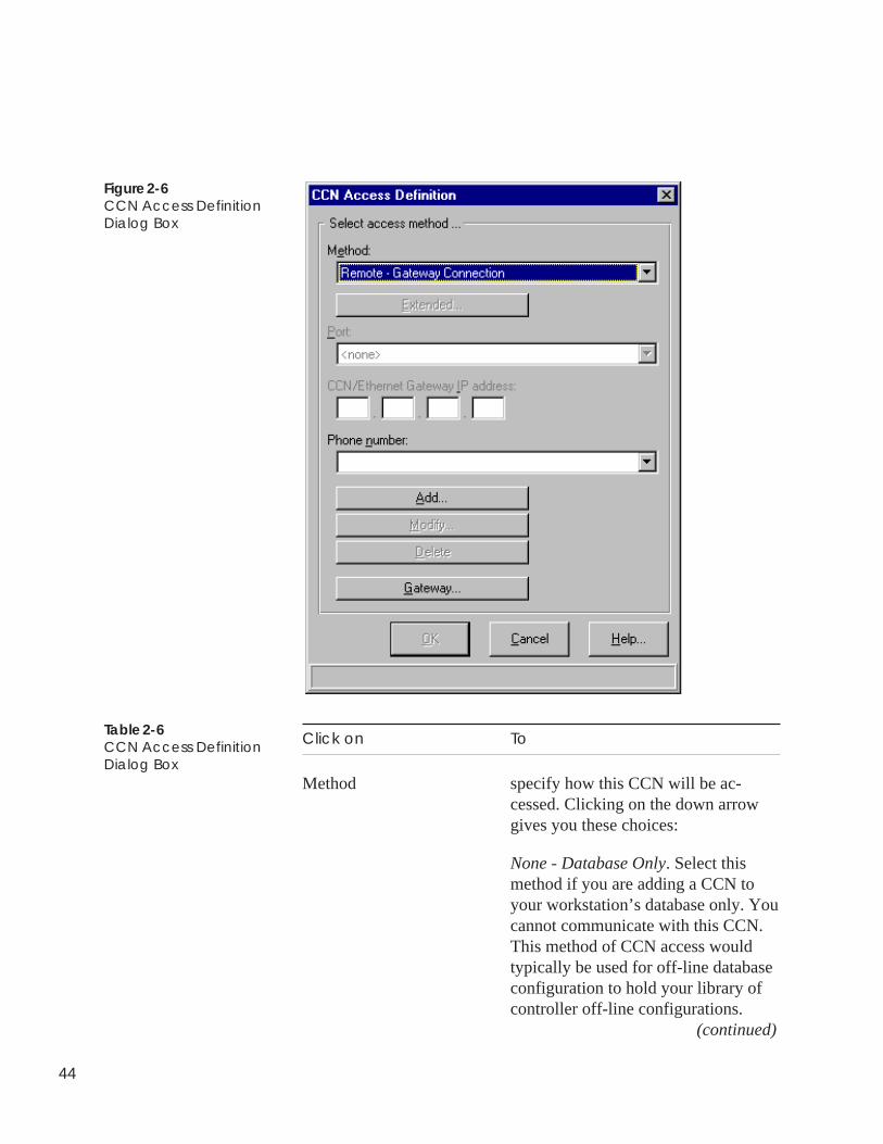
44
Click on To
Method specify how this CCN will be ac-cessed. Clicking on the down arrowgives you these choices:
None - Database Only. Select thismethod if you are adding a CCN toyour workstation’s database only. Youcannot communicate with this CCN.This method of CCN access wouldtypically be used for off-line databaseconfiguration to hold your library ofcontroller off-line configurations.
(continued)
Figure 2-6CCN Access DefinitionDialog Box
Table 2-6CCN Access DefinitionDialog Box
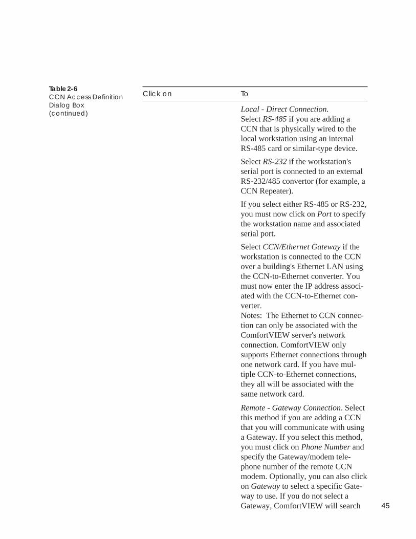
45
Table 2-6CCN Access DefinitionDialog Box(continued)
Click on To
Local - Direct Connection.Select RS-485 if you are adding aCCN that is physically wired to thelocal workstation using an internalRS-485 card or similar-type device.
Select RS-232 if the workstation'sserial port is connected to an externalRS-232/485 convertor (for example, aCCN Repeater).
If you select either RS-485 or RS-232,you must now click on Port to specifythe workstation name and associatedserial port.
Select CCN/Ethernet Gateway if theworkstation is connected to the CCNover a building's Ethernet LAN usingthe CCN-to-Ethernet converter. Youmust now enter the IP address associ-ated with the CCN-to-Ethernet con-verter.Notes: The Ethernet to CCN connec-tion can only be associated with theComfortVIEW server's networkconnection. ComfortVIEW onlysupports Ethernet connections throughone network card. If you have mul-tiple CCN-to-Ethernet connections,they all will be associated with thesame network card.
Remote - Gateway Connection. Selectthis method if you are adding a CCNthat you will communicate with usinga Gateway. If you select this method,you must click on Phone Number andspecify the Gateway/modem tele-phone number of the remote CCNmodem. Optionally, you can also clickon Gateway to select a specific Gate-way to use. If you do not select aGateway, ComfortVIEW will search
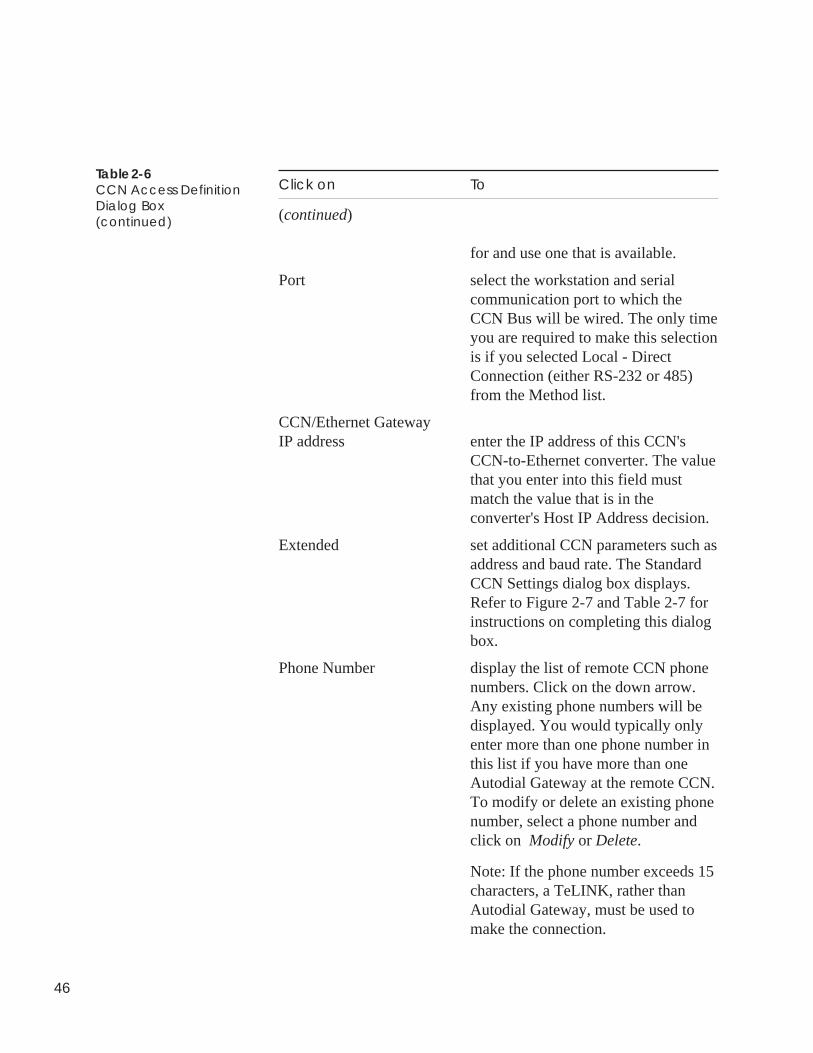
46
Click on To
(continued)
for and use one that is available.
Port select the workstation and serialcommunication port to which theCCN Bus will be wired. The only timeyou are required to make this selectionis if you selected Local - DirectConnection (either RS-232 or 485)from the Method list.
CCN/Ethernet GatewayIP address enter the IP address of this CCN's
CCN-to-Ethernet converter. The valuethat you enter into this field mustmatch the value that is in theconverter's Host IP Address decision.
Extended set additional CCN parameters such asaddress and baud rate. The StandardCCN Settings dialog box displays.Refer to Figure 2-7 and Table 2-7 forinstructions on completing this dialogbox.
Phone Number display the list of remote CCN phonenumbers. Click on the down arrow.Any existing phone numbers will bedisplayed. You would typically onlyenter more than one phone number inthis list if you have more than oneAutodial Gateway at the remote CCN.To modify or delete an existing phonenumber, select a phone number andclick on Modify or Delete.
Note: If the phone number exceeds 15characters, a TeLINK, rather thanAutodial Gateway, must be used tomake the connection.
Table 2-6CCN Access DefinitionDialog Box(continued)
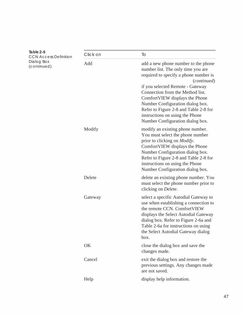
47
Table 2-6CCN Access DefinitionDialog Box(continued)
Click on To
Add add a new phone number to the phonenumber list. The only time you arerequired to specify a phone number is
(continued)if you selected Remote - GatewayConnection from the Method list.ComfortVIEW displays the PhoneNumber Configuration dialog box.Refer to Figure 2-8 and Table 2-8 forinstructions on using the PhoneNumber Configuration dialog box.
Modify modify an existing phone number.You must select the phone numberprior to clicking on Modify.ComfortVIEW displays the PhoneNumber Configuration dialog box.Refer to Figure 2-8 and Table 2-8 forinstructions on using the PhoneNumber Configuration dialog box.
Delete delete an existing phone number. Youmust select the phone number prior toclicking on Delete.
Gateway select a specific Autodial Gateway touse when establishing a connection tothe remote CCN. ComfortVIEWdisplays the Select Autodial Gatewaydialog box. Refer to Figure 2-6a andTable 2-6a for instructions on usingthe Select Autodial Gateway dialogbox.
OK close the dialog box and save thechanges made.
Cancel exit the dialog box and restore theprevious settings. Any changes madeare not saved.
Help display help information.
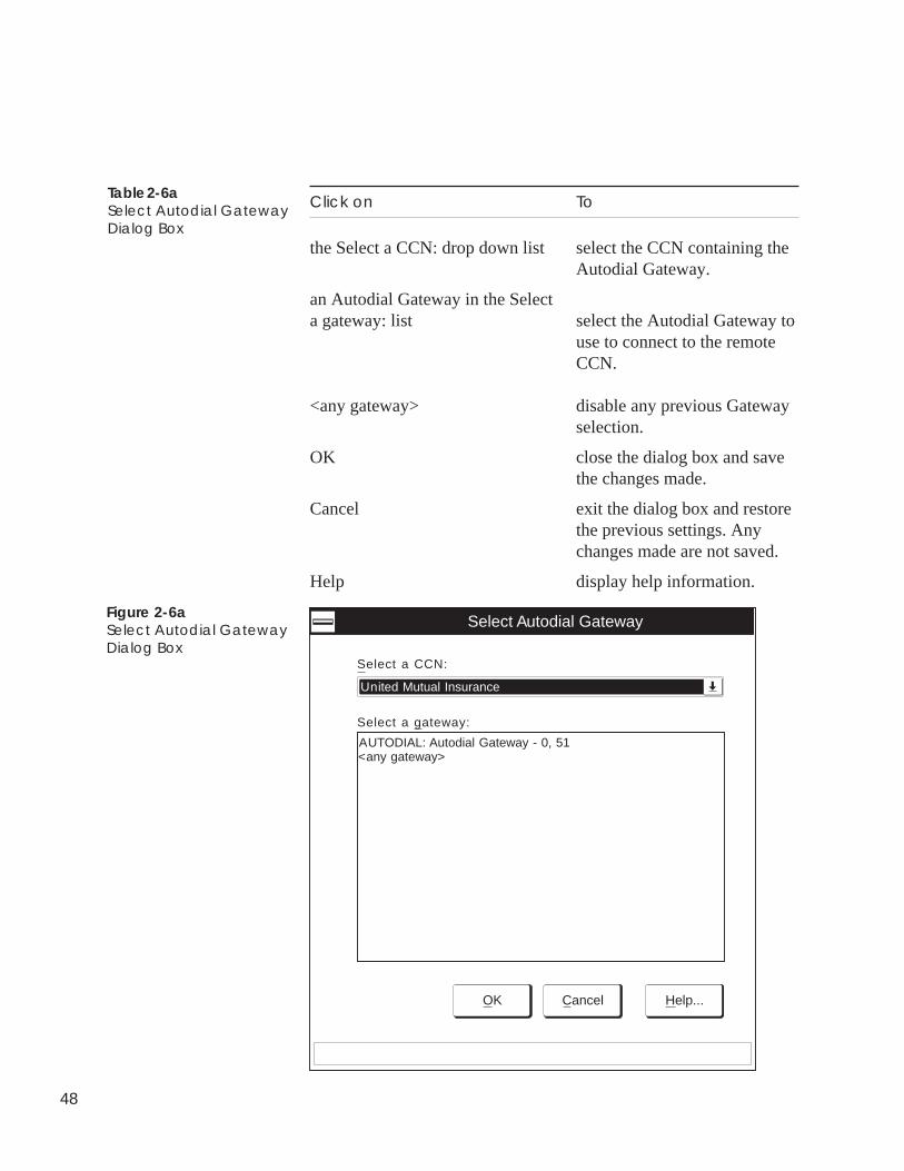
48
Click on To
the Select a CCN: drop down list select the CCN containing theAutodial Gateway.
an Autodial Gateway in the Selecta gateway: list select the Autodial Gateway to
use to connect to the remoteCCN.
<any gateway> disable any previous Gatewayselection.
OK close the dialog box and savethe changes made.
Cancel exit the dialog box and restorethe previous settings. Anychanges made are not saved.
Help display help information.
Table 2-6aSelect Autodial GatewayDialog Box
Figure 2-6aSelect Autodial GatewayDialog Box
Select Autodial Gateway
OK Cancel Help...
Select a CCN:
Select a gateway:
United Mutual Insurance
AUTODIAL: Autodial Gateway - 0, 51<any gateway>
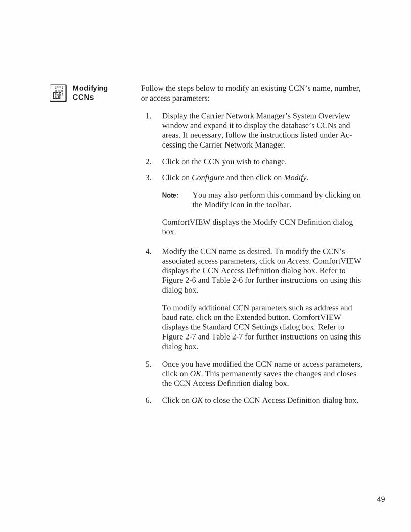
49
ModifyingCCNs
Follow the steps below to modify an existing CCN’s name, number,or access parameters:
1. Display the Carrier Network Manager’s System Overviewwindow and expand it to display the database’s CCNs andareas. If necessary, follow the instructions listed under Ac-cessing the Carrier Network Manager.
2. Click on the CCN you wish to change.
3. Click on Configure and then click on Modify.
Note: You may also perform this command by clicking onthe Modify icon in the toolbar.
ComfortVIEW displays the Modify CCN Definition dialogbox.
4. Modify the CCN name as desired. To modify the CCN’sassociated access parameters, click on Access. ComfortVIEWdisplays the CCN Access Definition dialog box. Refer toFigure 2-6 and Table 2-6 for further instructions on using thisdialog box.
To modify additional CCN parameters such as address andbaud rate, click on the Extended button. ComfortVIEWdisplays the Standard CCN Settings dialog box. Refer toFigure 2-7 and Table 2-7 for further instructions on using thisdialog box.
5. Once you have modified the CCN name or access parameters,click on OK. This permanently saves the changes and closesthe CCN Access Definition dialog box.
6. Click on OK to close the CCN Access Definition dialog box.
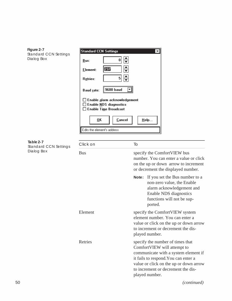
50
Figure 2-7Standard CCN SettingsDialog Box
Click on To
Bus specify the ComfortVIEW busnumber. You can enter a value or clickon the up or down arrow to incrementor decrement the displayed number.
Note: If you set the Bus number to anon-zero value, the Enablealarm acknowledgement andEnable NDS diagnosticsfunctions will not be sup-ported.
Element specify the ComfortVIEW systemelement number. You can enter avalue or click on the up or down arrowto increment or decrement the dis-played number.
Retries specify the number of times thatComfortVIEW will attempt tocommunicate with a system element ifit fails to respond.You can enter avalue or click on the up or down arrowto increment or decrement the dis-played number.
(continued)
Table 2-7Standard CCN SettingsDialog Box
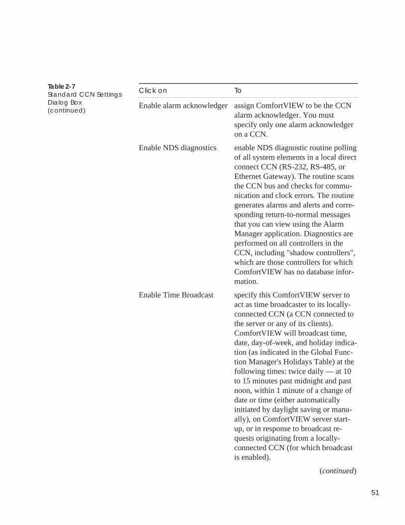
51
Table 2-7Standard CCN SettingsDialog Box(continued)
Click on To
Enable alarm acknowledger assign ComfortVIEW to be the CCNalarm acknowledger. You mustspecify only one alarm acknowledgeron a CCN.
Enable NDS diagnostics enable NDS diagnostic routine pollingof all system elements in a local directconnect CCN (RS-232, RS-485, orEthernet Gateway). The routine scansthe CCN bus and checks for commu-nication and clock errors. The routinegenerates alarms and alerts and corre-sponding return-to-normal messagesthat you can view using the AlarmManager application. Diagnostics areperformed on all controllers in theCCN, including "shadow controllers",which are those controllers for whichComfortVIEW has no database infor-mation.
Enable Time Broadcast specify this ComfortVIEW server toact as time broadcaster to its locally-connected CCN (a CCN connected tothe server or any of its clients).ComfortVIEW will broadcast time,date, day-of-week, and holiday indica-tion (as indicated in the Global Func-tion Manager's Holidays Table) at thefollowing times: twice daily — at 10to 15 minutes past midnight and pastnoon, within 1 minute of a change ofdate or time (either automaticallyinitiated by daylight saving or manu-ally), on ComfortVIEW server start-up, or in response to broadcast re-quests originating from a locally-connected CCN (for which broadcastis enabled).
(continued)
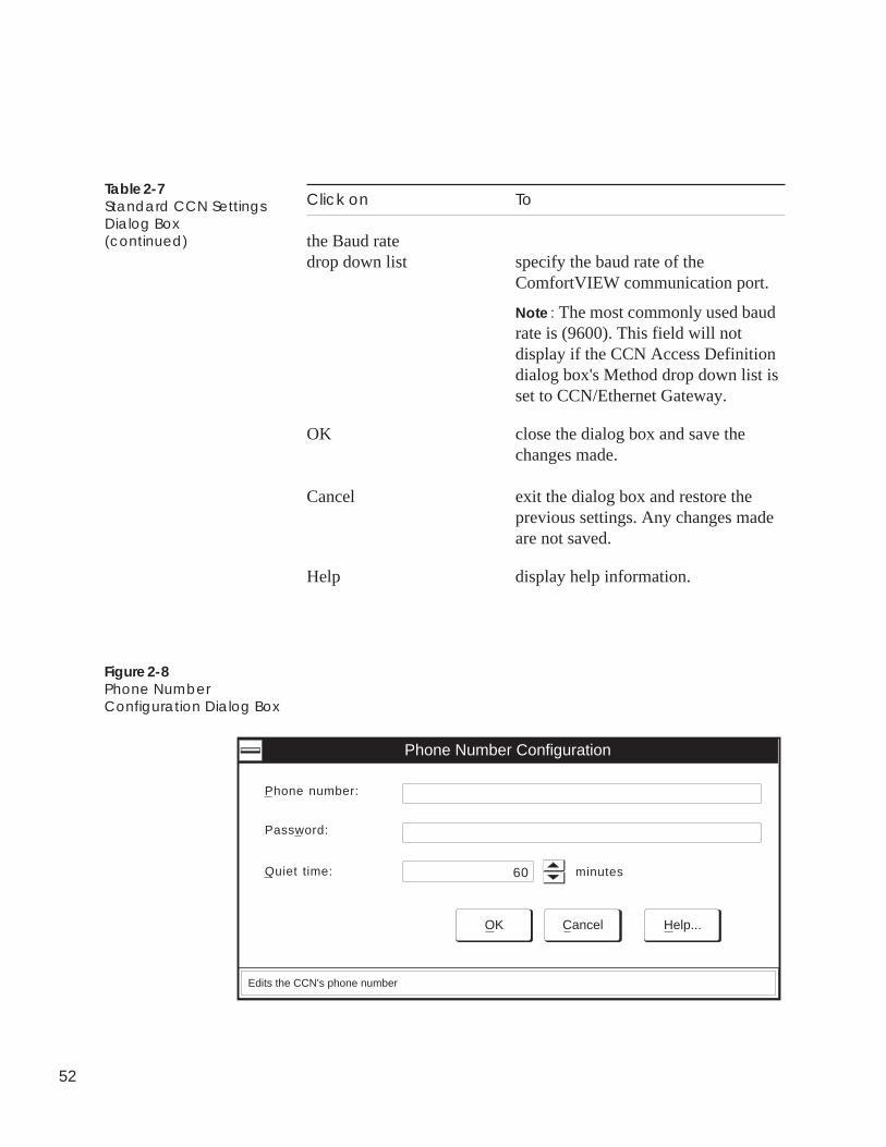
52
Click on To
the Baud ratedrop down list specify the baud rate of the
ComfortVIEW communication port.
Note : The most commonly used baudrate is (9600). This field will notdisplay if the CCN Access Definitiondialog box's Method drop down list isset to CCN/Ethernet Gateway.
OK close the dialog box and save thechanges made.
Cancel exit the dialog box and restore theprevious settings. Any changes madeare not saved.
Help display help information.
Table 2-7Standard CCN SettingsDialog Box(continued)
Phone Number Configuration
Phone number:
minutes
OK Cancel Help...
Password:
Quiet time:
Edits the CCN's phone number
60
Figure 2-8Phone NumberConfiguration Dialog Box
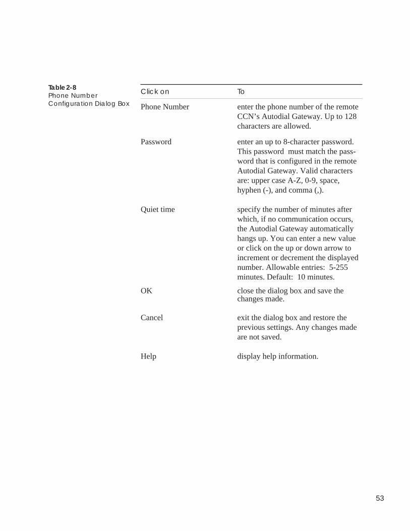
53
OK close the dialog box and save thechanges made.
Cancel exit the dialog box and restore theprevious settings. Any changes madeare not saved.
Help display help information.
Table 2-8Phone NumberConfiguration Dialog Box
Click on To
Phone Number enter the phone number of the remoteCCN’s Autodial Gateway. Up to 128characters are allowed.
Password enter an up to 8-character password.This password must match the pass-word that is configured in the remoteAutodial Gateway. Valid charactersare: upper case A-Z, 0-9, space,hyphen (-), and comma (,).
Quiet time specify the number of minutes afterwhich, if no communication occurs,the Autodial Gateway automaticallyhangs up. You can enter a new valueor click on the up or down arrow toincrement or decrement the displayednumber. Allowable entries: 5-255minutes. Default: 10 minutes.
54
Follow the steps below to add a new area into the ComfortVIEWdatabase.
An area is a logical grouping of system elements within a CCN. Forexample, an area could be a building, a floor, a wing, or a chillerplant.
1. Display the Carrier Network Manager’s System Overviewwindow and expand it to display the database’s CCNs andareas. If necessary, follow the instructions listed under Ac-cessing the Carrier Network Manager.
2. Click on the CCN in which the new area will appear.
3. Click on Configure and then click on New.
Note: You may also perform this command by clicking onthe Add New icon in the toolbar.
ComfortVIEW displays the Add New dialog box (shown inFigure 2-4). The Area button will be selected.
4. Click on OK.
ComfortVIEW displays the New Area Definition dialog box(shown in Figure 2-9). The CCN name will be displayed inthe Area name edit box.
Note: It is recommended that you append the area name tothe CCN name. ComfortVIEW Alarm Manager andReport Panel applications identify alarms and pointsusing the area name. Creating area names thatconsist of both the CCN and area name will assistyou in identifying alarm and report points.
5. Click in the dialog box after the CCN name and enter thename of the new area in the Area name edit box. Up to 48characters are allowed.
6. Click on OK.
The new area name displays in alphabetical order in theSystem Overview window under its associated CCN.
To Add aNew Area
Adding/Modifying Areas
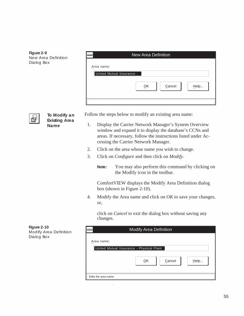
55
Figure 2-9New Area DefinitionDialog Box
United Mutual Insurance -
New Area Definition
OK Cancel Help...
Area name:
Follow the steps below to modify an existing area name:
1. Display the Carrier Network Manager’s System Overviewwindow and expand it to display the database’s CCNs andareas. If necessary, follow the instructions listed under Ac-cessing the Carrier Network Manager.
2. Click on the area whose name you wish to change.
3. Click on Configure and then click on Modify.
Note: You may also perform this command by clicking onthe Modify icon in the toolbar.
ComfortVIEW displays the Modify Area Definition dialogbox (shown in Figure 2-10).
4. Modify the Area name and click on OK to save your changes,or,
click on Cancel to exit the dialog box without saving anychanges.
To Modify anExisting AreaName
United Mutual Insurance - Physical Plant
Modify Area Definition
OK Cancel Help...
Area name:
Edits the area name
Figure 2-10Modify Area DefinitionDialog Box
56
Follow the steps below to delete a CCN or area from theComfortVIEW database:
Note: Deleting a CCN also deletes all areas and controllersassigned to the CCN.
1. Display the Carrier Network Manager’s System Overviewwindow and expand it to display the database’s CCNs andareas. If necessary, follow the instructions listed under Ac-cessing the Carrier Network Manager.
2. Click on the CCN to be deleted.
3. Click on the Configure menu item and then click on Delete.
Note: You may also perform this command by clicking onthe Delete icon in the toolbar.
ComfortVIEW displays a dialog box asking for confirmationbefore deleting the CCN.
4. Click on Yes to initiate the deletion or click on No to preventthe deletion from taking place.
If you click on Yes, ComfortVIEW prompts you again beforedeleting the CCN.
5. Click on Yes to complete the deletion or click on No toprevent the deletion from taking place.
Note: If ComfortVIEW displays the message CCN Is InUse, you have attempted to delete a CCN containinga controller that is currently being accessed by youor another ComfortVIEW operator. Attempt thedeletion again when the controller is available.
Deleting CCNsand Areas
To Delete a CCN
57
Follow the steps below to delete an area:
Note: Deleting an area also deletes all controllers assigned to thearea.
1. Display the Carrier Network Manager’s System Overviewwindow and expand it to display the database’s CCNs andareas. If necessary, follow the instructions listed under Ac-cessing the Carrier Network Manager.
2. Click on the area to be deleted.
3. Click on the Configure menu item and then click on Delete.
Note: You may also perform this command by clicking onthe Delete icon in the toolbar.
ComfortVIEW displays a dialog box asking for confirmationbefore deleting the area.
4. Click on Yes to initiate the deletion or click on No to preventthe deletion from taking place.
If you click on Yes, ComfortVIEW prompts you again beforedeleting the area.
5. Click on Yes or No.
To Deletean Area
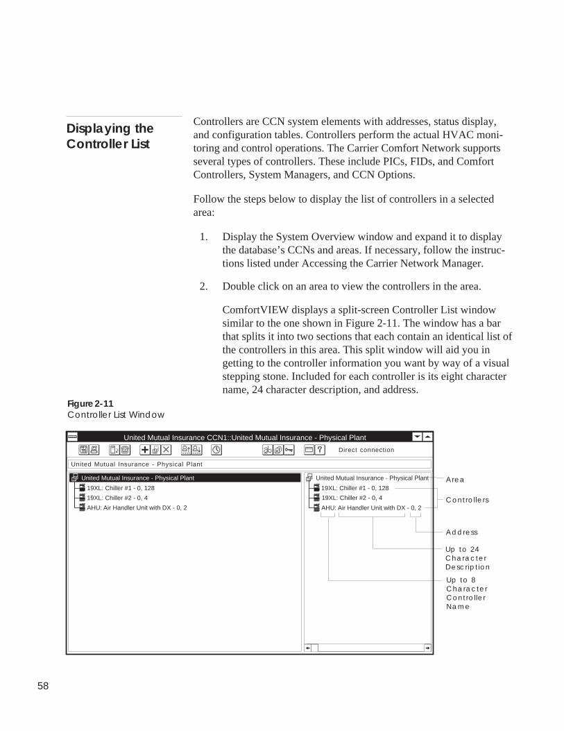
58
Controllers are CCN system elements with addresses, status display,and configuration tables. Controllers perform the actual HVAC moni-toring and control operations. The Carrier Comfort Network supportsseveral types of controllers. These include PICs, FIDs, and ComfortControllers, System Managers, and CCN Options.
Follow the steps below to display the list of controllers in a selectedarea:
1. Display the System Overview window and expand it to displaythe database’s CCNs and areas. If necessary, follow the instruc-tions listed under Accessing the Carrier Network Manager.
2. Double click on an area to view the controllers in the area.
ComfortVIEW displays a split-screen Controller List windowsimilar to the one shown in Figure 2-11. The window has a barthat splits it into two sections that each contain an identical list ofthe controllers in this area. This split window will aid you ingetting to the controller information you want by way of a visualstepping stone. Included for each controller is its eight charactername, 24 character description, and address.
Displaying theController List
Figure 2-11Controller List Window
Area
United Mutual Insurance CCN1::United Mutual Insurance - Physical Plant
19XL: Chiller #1 - 0, 128
United Mutual Insurance - Physical Plant
United Mutual Insurance - Physical Plant
United Mutual Insurance - Physical Plant
19XL: Chiller #2 - 0, 4
AHU: Air Handler Unit with DX - 0, 2Controllers
Up to 8CharacterControllerName
Up to 24CharacterDescription
Address
Direct connection
19XL: Chiller #1 - 0, 128
19XL: Chiller #2 - 0, 4
AHU: Air Handler Unit with DX - 0, 2
59
While viewing the controller list you can use the Windows menu'sJump to Table/WorkSPACE command to display a selected systemelement's status display table or linked WorkSPACE. For moreinformation on this command, refer to the menu command summaryat the end of this Carrier Network Manager chapter.
You can sort the presentation of the controller list alphabetically bycontroller name, numerically by ascending address, or by sort keynumber. By default on launching the Carrier Network Managerapplication, the controller list appears sorted by sort key.
1. Click on the Options menu item and then click on Sort.
Note: You may also sort the Controller List by clicking onthe Sort by Name, Sort by Address, or Sort by SortKey icons in the toolbar.
2. Perform one of the following actions:
• Click on Name to sort the list alphabetically by name.
• Click on Address to sort it in ascending numerical order byaddress.
• Click on Sort to sort the list in ascending numerical orderby sort key.
Note: Sort keys are assigned when you add controllers tothe ComfortVIEW database. For further informationon sort keys, refer to the Adding/Modifying Con-trollers section of this chapter.
The Controller List window re-displays sorted accordingly. Whensorted alphabetically, controller names beginning with numbersappear at the beginning of the list.
You can move the window’s split bar so that you have more room todisplay information in either section.
1. Position the mouse on the split bar.
The mouse pointer turns into a double bar with two arrows.
Displaying aController's StatusDisplay Table orWorkSPACE
Sorting theController List
Moving the Split Bar
60
2. Press and hold down the mouse button, and move the mouse leftor right to re-position the split bar.
3. Release the mouse button when the split bar is in the desiredlocation.
You can also resize and move the Controller List window. For moreinformation about ComfortVIEW windows, see InterpretingComfortVIEW Screens in the Introduction of this manual.
Follow the steps below to add a controller (CCN system element) tothe ComfortVIEW database.
1. Display the Controller List window. If necessary, follow theinstructions listed under Displaying the Controller List.
2. Click on Configure and then click on New.
Note: You may also perform this command by clicking onthe Add New icon in the toolbar.
ComfortVIEW displays the CCN Element Definition dialog box(shown in Figure 2-12).
3. Enter the Element name, description, address (bus and elementnumber), and sort key for the new controller. Specify whetherthis controller should be assigned a high priority NDS diagnosticscan rate.
Refer to Figure 2-12 and Table 2-12 for instructions on usingthis dialog box.
4. Select the action that will add the controller’s configurationtables by clicking on one of the following:
• Upload• Copy from• Import from
Refer to Table 2-12 for information on each of these functions.
To Add a NewController
Adding/ModifyingControllers
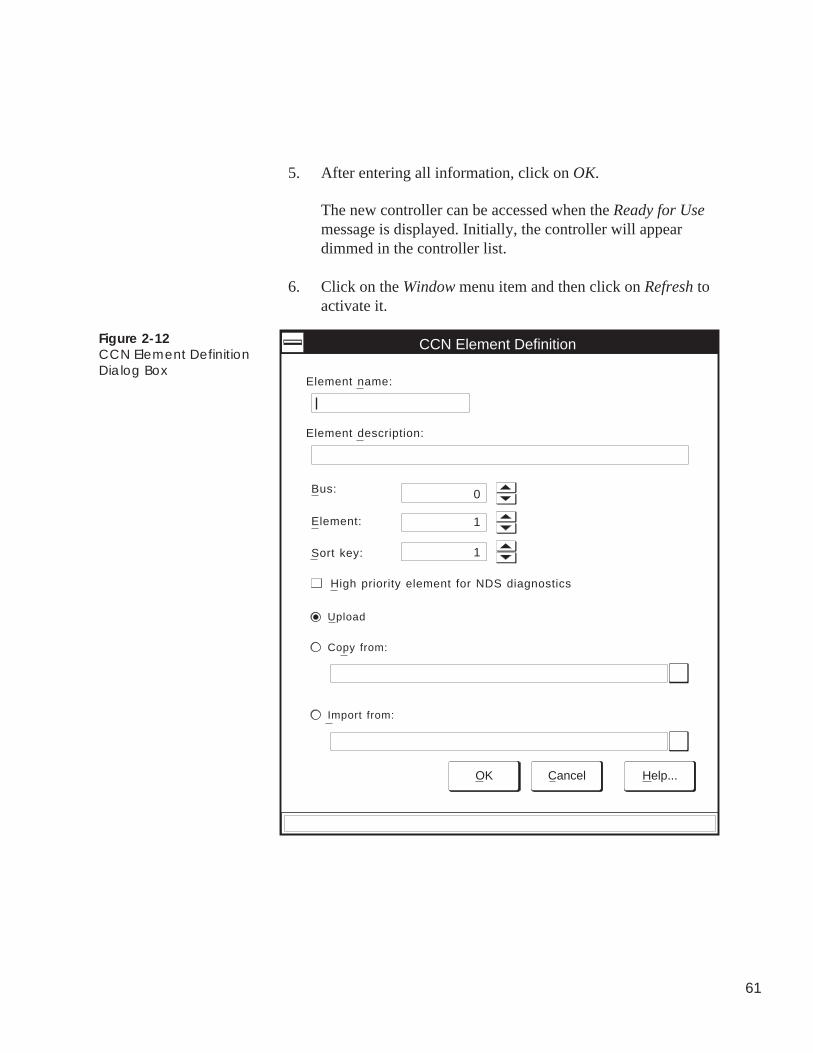
61
5. After entering all information, click on OK.
The new controller can be accessed when the Ready for Usemessage is displayed. Initially, the controller will appeardimmed in the controller list.
6. Click on the Window menu item and then click on Refresh toactivate it.
Figure 2-12CCN Element DefinitionDialog Box
Sort key:
Element description:
CCN Element Definition
Element name:
Bus: 0
1Element:
1
OK Cancel Help...
Copy from:
Upload
Import from:
High priority element for NDS diagnostics
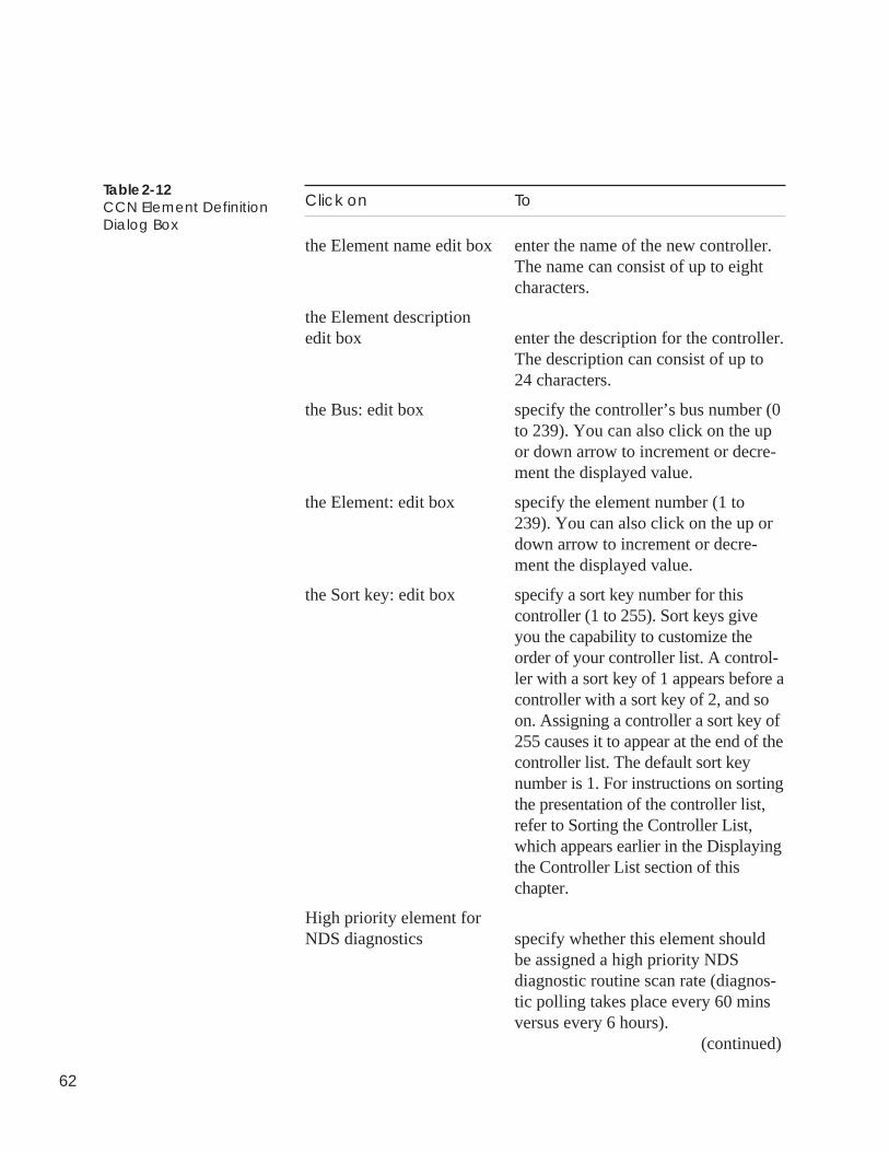
62
Table 2-12CCN Element DefinitionDialog Box
Click on To
the Element name edit box enter the name of the new controller.The name can consist of up to eightcharacters.
the Element descriptionedit box enter the description for the controller.
The description can consist of up to24 characters.
the Bus: edit box specify the controller’s bus number (0to 239). You can also click on the upor down arrow to increment or decre-ment the displayed value.
the Element: edit box specify the element number (1 to239). You can also click on the up ordown arrow to increment or decre-ment the displayed value.
the Sort key: edit box specify a sort key number for thiscontroller (1 to 255). Sort keys giveyou the capability to customize theorder of your controller list. A control-ler with a sort key of 1 appears before acontroller with a sort key of 2, and soon. Assigning a controller a sort key of255 causes it to appear at the end of thecontroller list. The default sort keynumber is 1. For instructions on sortingthe presentation of the controller list,refer to Sorting the Controller List,which appears earlier in the Displayingthe Controller List section of thischapter.
High priority element forNDS diagnostics specify whether this element should
be assigned a high priority NDSdiagnostic routine scan rate (diagnos-tic polling takes place every 60 minsversus every 6 hours).
(continued)
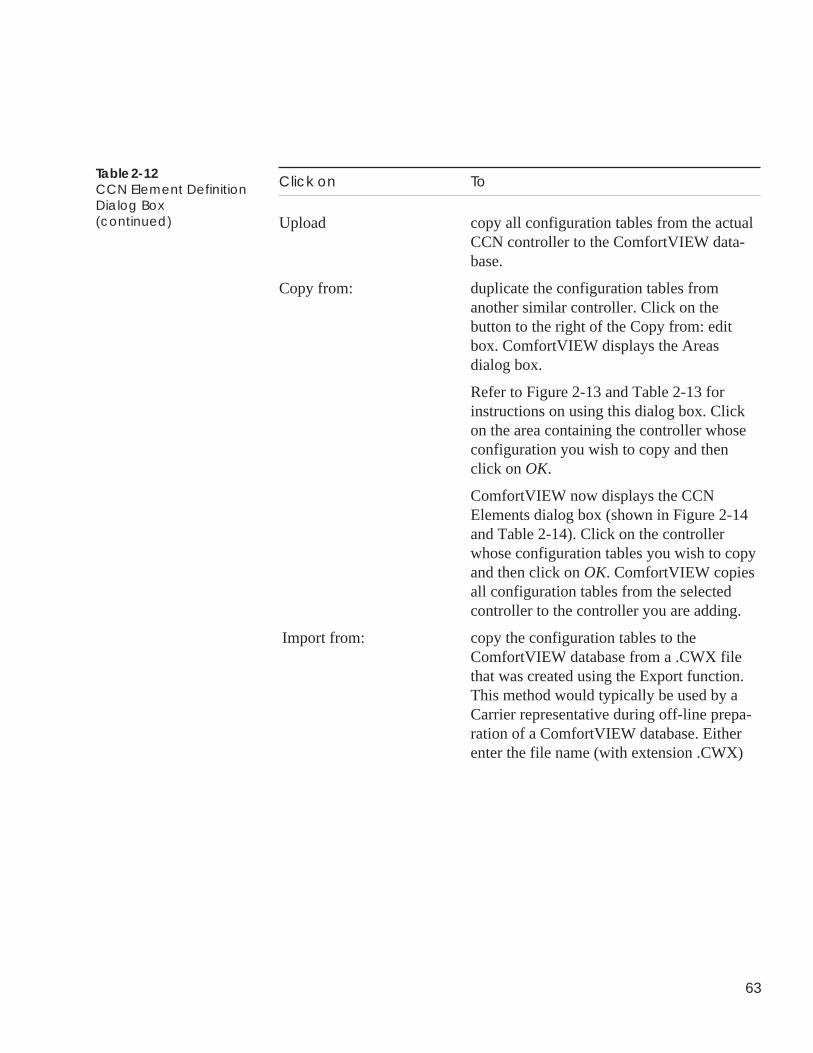
63
Click on To
Upload copy all configuration tables from the actualCCN controller to the ComfortVIEW data-base.
Copy from: duplicate the configuration tables fromanother similar controller. Click on thebutton to the right of the Copy from: editbox. ComfortVIEW displays the Areasdialog box.
Refer to Figure 2-13 and Table 2-13 forinstructions on using this dialog box. Clickon the area containing the controller whoseconfiguration you wish to copy and thenclick on OK.
ComfortVIEW now displays the CCNElements dialog box (shown in Figure 2-14and Table 2-14). Click on the controllerwhose configuration tables you wish to copyand then click on OK. ComfortVIEW copiesall configuration tables from the selectedcontroller to the controller you are adding.
Import from: copy the configuration tables to theComfortVIEW database from a .CWX filethat was created using the Export function.This method would typically be used by aCarrier representative during off-line prepa-ration of a ComfortVIEW database. Eitherenter the file name (with extension .CWX)
Table 2-12CCN Element DefinitionDialog Box(continued)
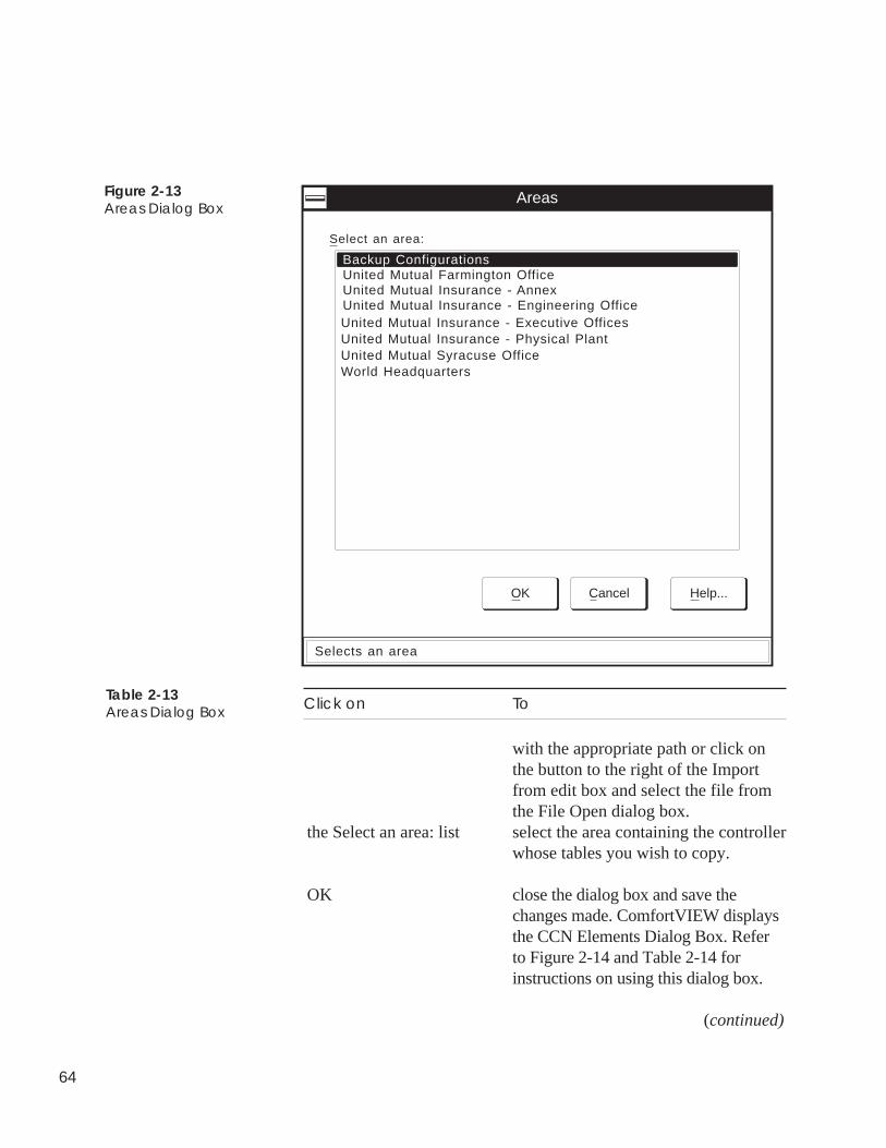
64
Click on To
with the appropriate path or click onthe button to the right of the Importfrom edit box and select the file fromthe File Open dialog box.
the Select an area: list select the area containing the controllerwhose tables you wish to copy.
OK close the dialog box and save thechanges made. ComfortVIEW displaysthe CCN Elements Dialog Box. Referto Figure 2-14 and Table 2-14 forinstructions on using this dialog box.
(continued)
Figure 2-13Areas Dialog Box
Backup Configurations
Areas
OK Cancel Help...
Select an area:
United Mutual Farmington OfficeUnited Mutual Insurance - AnnexUnited Mutual Insurance - Engineering OfficeUnited Mutual Insurance - Executive OfficesUnited Mutual Insurance - Physical PlantUnited Mutual Syracuse OfficeWorld Headquarters
Selects an area
Table 2-13Areas Dialog Box
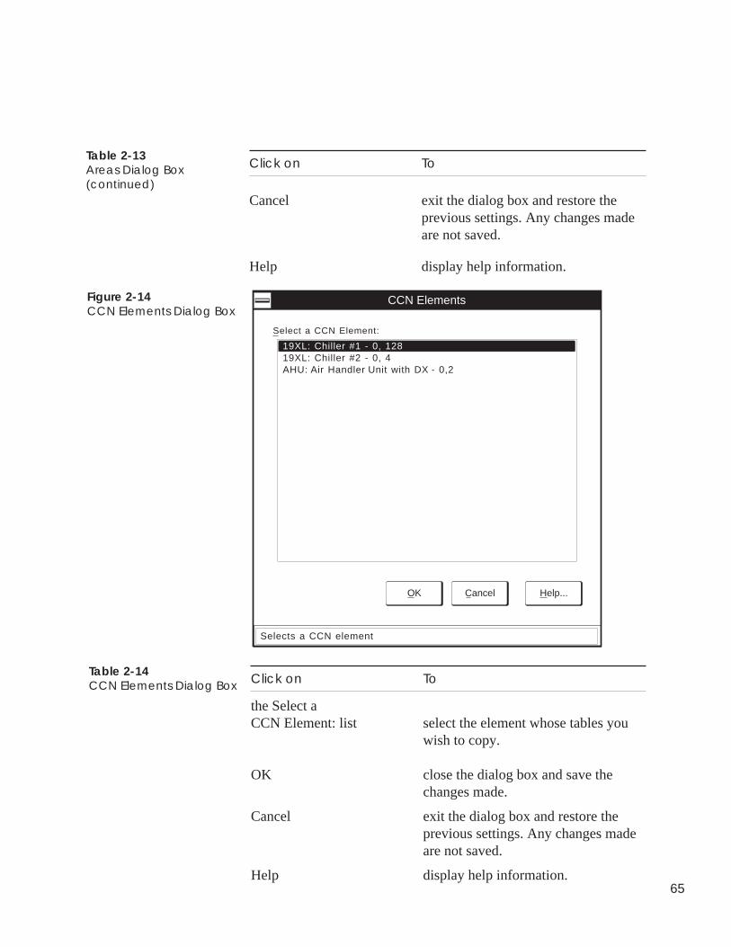
65
Click on To
Cancel exit the dialog box and restore theprevious settings. Any changes madeare not saved.
Help display help information.
Table 2-13Areas Dialog Box(continued)
Figure 2-14CCN Elements Dialog Box
19XL: Chiller #2 - 0, 4
CCN Elements
OK Cancel Help...
Select a CCN Element:
AHU: Air Handler Unit with DX - 0,2
19XL: Chiller #1 - 0, 128
Selects a CCN element
Click on To
the Select aCCN Element: list select the element whose tables you
wish to copy.
OK close the dialog box and save thechanges made.
Cancel exit the dialog box and restore theprevious settings. Any changes madeare not saved.
Help display help information.
Table 2-14CCN Elements Dialog Box
66
To Modify anExistingController'sName orSort Key
Follow the steps below to modify an existing controller name,description, or sort key:
1. Display the Controller List window. If necessary, follow theinstructions listed under Displaying the Controller List.
2. Click on the controller whose name you wish to change.
3. Click on Configure and then click on Modify.
Note: You may also perform this command by clicking onthe Modify icon in the toolbar.
ComfortVIEW displays the CCN Element Definition dialogbox (shown in Figure 2-15).
4. If desired, modify the following information for theselected controller:
• Element name• Element description• Sort key• High priority NDS element
Refer to Figure 2-15 and Table 2-15 for instructions on usingthis dialog box.
5. After modifying the desired information, click on OK to closethe dialog box and save your modifications, or click onCancel to exit the box and restore the previous settings.
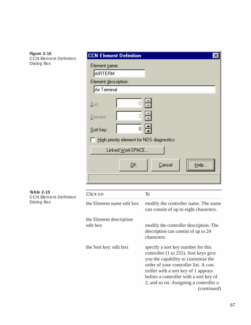
67
Figure 2-15CCN Element DefinitionDialog Box
Click on To
the Element name edit box modify the controller name. The namecan consist of up to eight characters.
the Element descriptionedit box modify the controller description. The
description can consist of up to 24characters.
the Sort key: edit box specify a sort key number for thiscontroller (1 to 255). Sort keys giveyou the capability to customize theorder of your controller list. A con-troller with a sort key of 1 appearsbefore a controller with a sort key of2, and so on. Assigning a controller a
(continued)
Table 2-15CCN Element DefinitionDialog Box
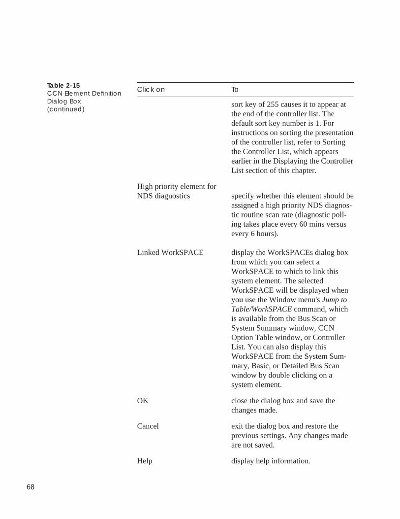
68
Table 2-15CCN Element DefinitionDialog Box(continued)
Click on To
sort key of 255 causes it to appear atthe end of the controller list. Thedefault sort key number is 1. Forinstructions on sorting the presentationof the controller list, refer to Sortingthe Controller List, which appearsearlier in the Displaying the ControllerList section of this chapter.
High priority element forNDS diagnostics specify whether this element should be
assigned a high priority NDS diagnos-tic routine scan rate (diagnostic poll-ing takes place every 60 mins versusevery 6 hours).
Linked WorkSPACE display the WorkSPACEs dialog boxfrom which you can select aWorkSPACE to which to link thissystem element. The selectedWorkSPACE will be displayed whenyou use the Window menu's Jump toTable/WorkSPACE command, whichis available from the Bus Scan orSystem Summary window, CCNOption Table window, or ControllerList. You can also display thisWorkSPACE from the System Sum-mary, Basic, or Detailed Bus Scanwindow by double clicking on asystem element.
OK close the dialog box and save thechanges made.
Cancel exit the dialog box and restore theprevious settings. Any changes madeare not saved.
Help display help information.
69
Follow the steps below to delete a controller. If you remove acontroller that contains CCN Options, ComfortVIEW deletes theoptions from the Options List that is displayed using the CCNOptions command in the CCN Tools menu. If any option’s configu-ration uses points from the deleted controller, modify the configura-tion of the affected option accordingly.
1. Display the Controller List window.
2. Click on the controller you wish to delete.
Note: ComfortVIEW allows you to delete multiple control-lers. Use the Windows-standard mouse or keyboardtechniques to select multiple controllers. You can,however, only select multiple controllers from theright side of the Controller List window.
3. Click on the Configure menu item and then click on Delete.
Note: You may also perform this command by clicking onthe Delete icon in the toolbar.
ComfortVIEW displays a dialog box asking for confirmationbefore deleting the controller.
4. Click on Yes or No. If you have selected multiple controllersand wish to delete all, click on Yes to All.
Note: If ComfortVIEW displays the message Controller IsIn Use, you have attempted to delete a controllerthat is currently being accessed by you or anotherComfortVIEW operator. Attempt the delete againwhen the controller is available.
DeletingControllers
70
Status display and maintenance tables contain real-time data for allcontroller points. Follow the steps below to display a controller’sstatus display or maintenance tables. For instructions on modifying(forcing) status display or maintenance table values, refer to theModifying Status Display or Maintenance Table Values section ofthis chapter.
1. Display the System Overview window and expand it todisplay the database’s CCNs and areas. If necessary, followthe instructions listed under Accessing the Carrier NetworkManager.
2. Display the controller list. If necessary, follow the instruc-tions listed under Displaying the Controller List.
3. Double click on a controller to view its table categories.
4. Double click on Status Display to view status display tablesor on Maintenance Display to view maintenance tables.
5. Double click on the table you wish to view.
Certain table categories may contain additional sub-catego-ries. If you select a table category of this type, another list ofsub-categories will be shown, and you should click on a sub-category from this list. Refer to Figure 2-16.
Sample status display and maintenance tables appear in thefollowing figures.
The Carrier Network Manager provides you with a short cut todisplay and modify a selected point's associated configuration,maintenance, time schedule, or setpoint table while you are viewingstatus display or maintenance tables. To display a point's associatedtables, click on the Configure menu item followed by clicking onConfiguration, Maintenance, Time Schedule, or Setpoint.
While you are viewing Comfort Controller status display tables, theCarrier Network Manager provides you with a means to list thenames of all Comfort Controller objects that are using a selectedstatus display point in their configuration. To display a point'sassociated objects, click on the Configure menu item followed byclicking on Reference tables. If desired, you can then display aselected object's associated configuration or maintenance table.These reference jumps are also available from magenta-highlightedComfort Controller maintenance table points.
Viewing StatusDisplay andMaintenanceTables
Table Jumps fromStatus Display andMaintenance Tables
Reference Jumpsfrom ComfortController StatusDisplay Tables
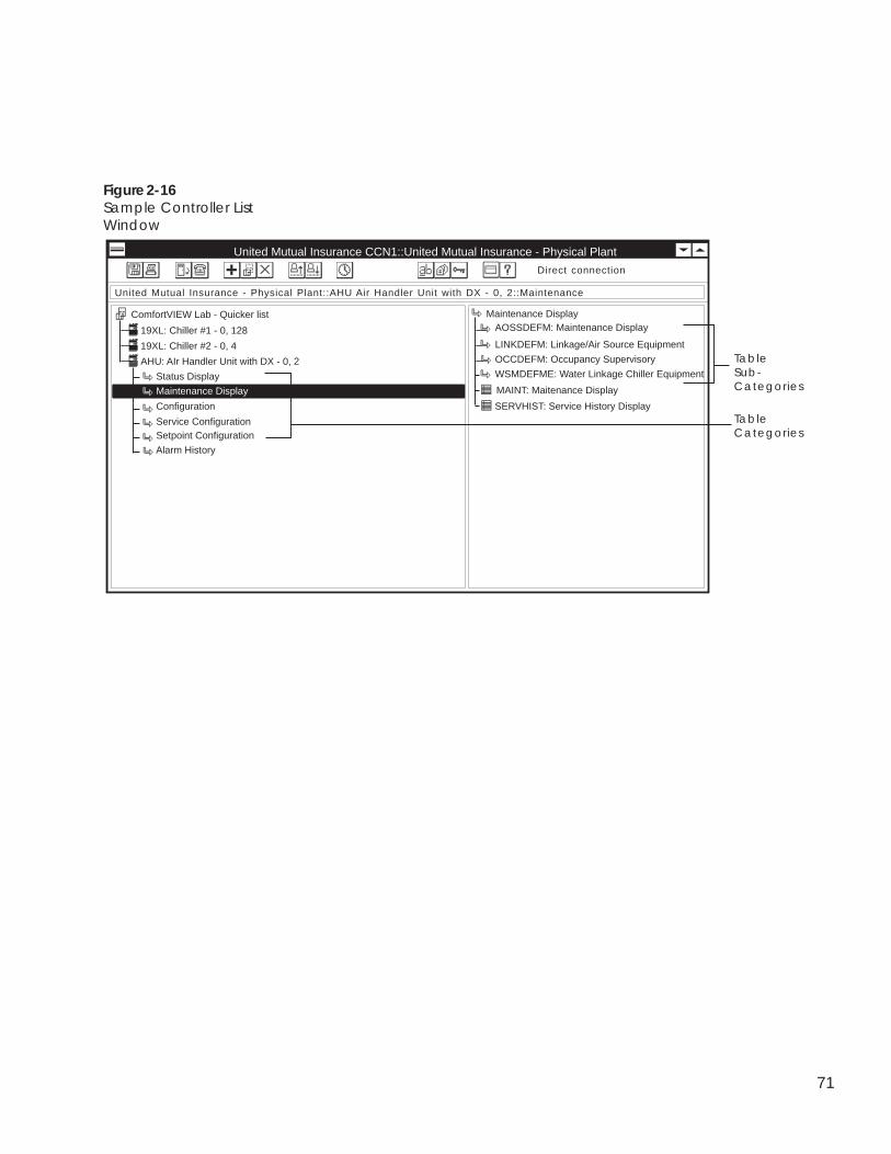
71
Figure 2-16Sample Controller ListWindow
United Mutual Insurance CCN1::United Mutual Insurance - Physical Plant
19XL: Chiller #1 - 0, 128
ComfortVIEW Lab - Quicker list
United Mutual Insurance - Physical Plant::AHU Air Handler Unit with DX - 0, 2::Maintenance
AOSSDEFM: Maintenance DisplayMaintenance Display
WSMDEFME: Water Linkage Chiller Equipment
LINKDEFM: Linkage/Air Source Equipment
OCCDEFM: Occupancy Supervisory19XL: Chiller #2 - 0, 4
AHU: AIr Handler Unit with DX - 0, 2
Direct connection
Status Display
Maintenance Display
Configuration
Service ConfigurationSetpoint Configuration
Table Categories
MAINT: Maitenance Display
SERVHIST: Service History Display
Table Sub-Categories
Alarm History
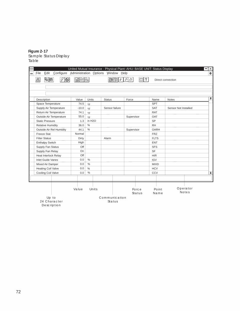
72
Figure 2-17Sample Status DisplayTable
AdministrationUnited Mutual Insurance - Physical Plant::AHU::BASE UNIT: Status Display
File Edit Configure Options HelpWindow
Description Value Units Status Force Name Notes
Space Temperature 74.5 OF SPT
Supply Air Temperature -10.0 OF Sensor failure SAT
Return Air Temperature 74.1 OF RAT
Outside Air Temperature 55.0 OF Supervisor OAT
Static Pressure 1.3 SP
Relative Humidity 36.0 RH
Outside Air Rel Humidity 44.1 Supervisor OARH
Freeze Stat Normal FRZ
Filter Status Dirty Alarm FLTS
Enthalpy Switch High ENT
Supply Fan Status Off SFS
Supply Fan Relay On SF
Heat Interlock Relay Off HIR
Inlet Guide Vanes 0.0 IGV
Mixed Air Damper 0.0 MIXD
Heating Coil Valve 0.0 HCV
Cooling Coil Valve 0.0 CCV
Direct connection
Value Units
Up to24 Character
Description
CommunicationStatus
in H2O
%
%
%
%
%
%
Sensor Not Installed
ForceStatus
PointName
OperatorNotes
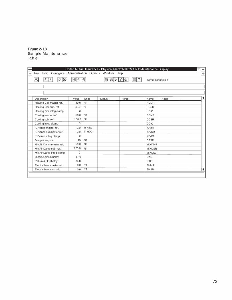
73
Figure 2-18Sample MaintenanceTable
AdministrationUnited Mutual Insurance - Physical Plant::AHU::MAINT: Maintenance Display
File Edit Configure Options HelpWindow
Description Value Units Status Force Name Notes
Heating Coil master ref. 40.0 OF HCMR
Heating Coil sub. ref. 40.0 OF HCSR
Heating Coil integ clamp 3 HCIC
Cooling master ref. 50.0 OF CCMR
Cooling sub. ref. 150.0 CCSR
Cooling integ clamp 3 CCIC
IG Vanes master ref. 0.0 IGVMR
IG Vanes submaster ref. 0.0 IGVSR
IG Vanes integ clamp 0 IGVIC
Damper setpoint 45 DPSP
Mix Air Damp master ref. 59.0 MIXDMR
Mix Air Damp sub. ref. 120.0 MIXDSR
Mix Air Damp integ clamp 0 MIXDIC
Outside Air Enthalpy 17.6 OAE
Return Air Enthalpy 24.8 RAE
Electric heat master ref. 0.0 EHMR
Electric heat sub. ref. 0.0 EHSR
in H2O
OF
in H2O
OF
OFOF
OFOF
Direct connection
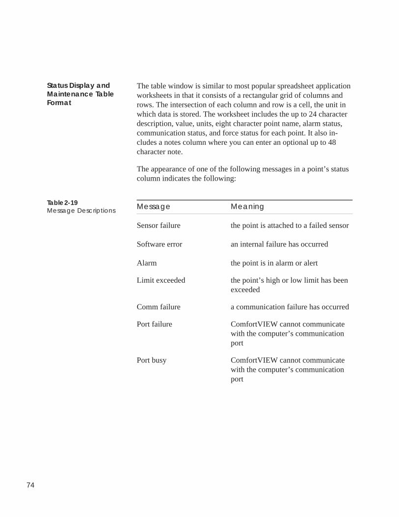
74
The table window is similar to most popular spreadsheet applicationworksheets in that it consists of a rectangular grid of columns androws. The intersection of each column and row is a cell, the unit inwhich data is stored. The worksheet includes the up to 24 characterdescription, value, units, eight character point name, alarm status,communication status, and force status for each point. It also in-cludes a notes column where you can enter an optional up to 48character note.
The appearance of one of the following messages in a point’s statuscolumn indicates the following:
Message Meaning
Sensor failure the point is attached to a failed sensor
Software error an internal failure has occurred
Alarm the point is in alarm or alert
Limit exceeded the point’s high or low limit has beenexceeded
Comm failure a communication failure has occurred
Port failure ComfortVIEW cannot communicatewith the computer’s communicationport
Port busy ComfortVIEW cannot communicatewith the computer’s communicationport
Status Display andMaintenance TableFormat
Table 2-19Message Descriptions
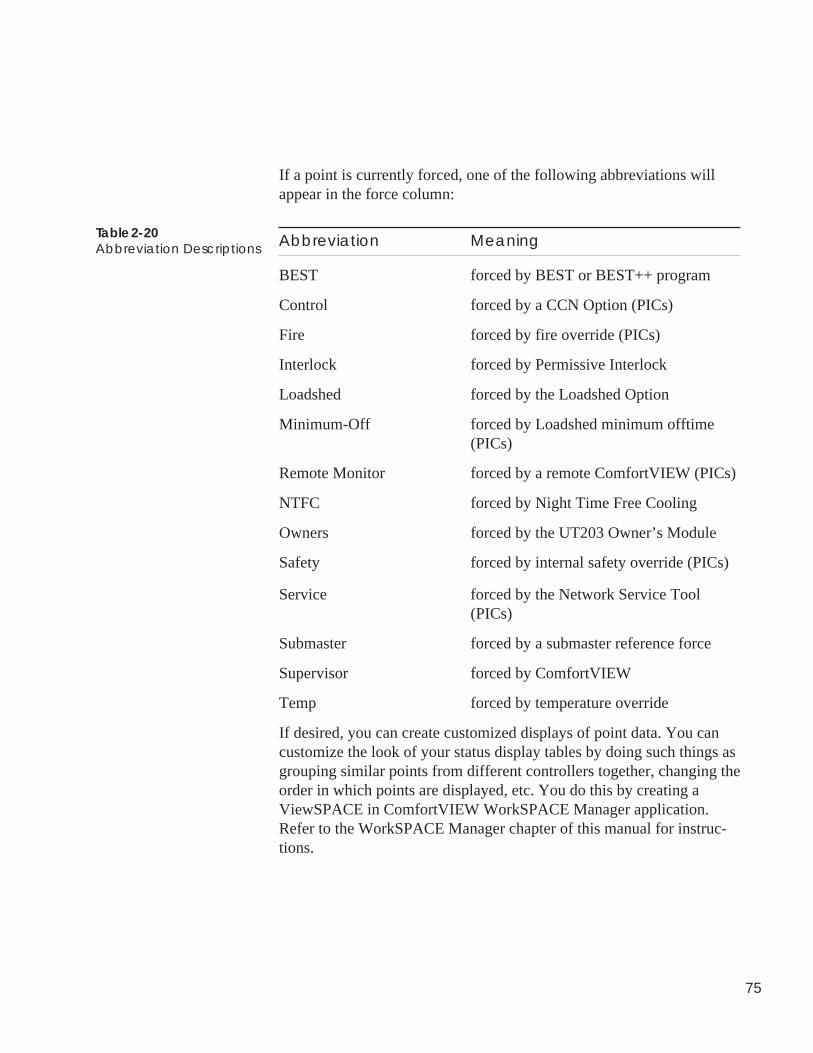
75
If a point is currently forced, one of the following abbreviations willappear in the force column:
Abbreviation Meaning
BEST forced by BEST or BEST++ program
Control forced by a CCN Option (PICs)
Fire forced by fire override (PICs)
Interlock forced by Permissive Interlock
Loadshed forced by the Loadshed Option
Minimum-Off forced by Loadshed minimum offtime(PICs)
Remote Monitor forced by a remote ComfortVIEW (PICs)
NTFC forced by Night Time Free Cooling
Owners forced by the UT203 Owner’s Module
Safety forced by internal safety override (PICs)
Service forced by the Network Service Tool(PICs)
Submaster forced by a submaster reference force
Supervisor forced by ComfortVIEW
Temp forced by temperature override
If desired, you can create customized displays of point data. You cancustomize the look of your status display tables by doing such things asgrouping similar points from different controllers together, changing theorder in which points are displayed, etc. You do this by creating aViewSPACE in ComfortVIEW WorkSPACE Manager application.Refer to the WorkSPACE Manager chapter of this manual for instruc-tions.
Table 2-20Abbreviation Descriptions
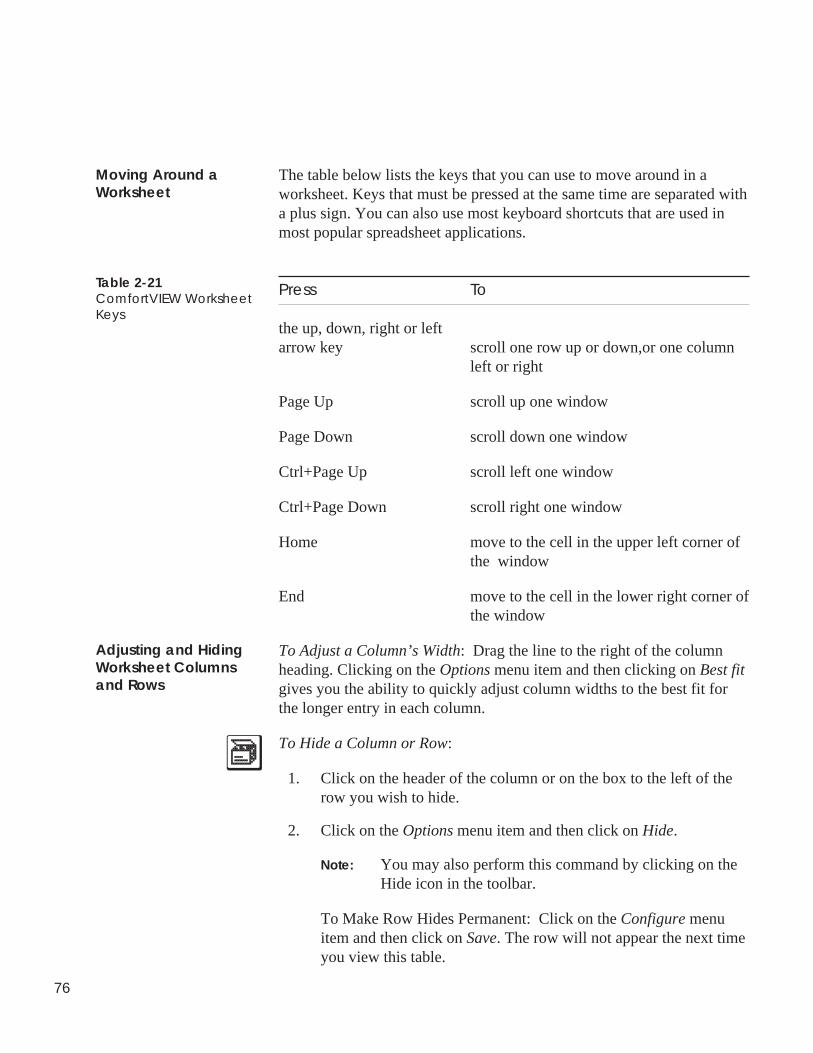
76
The table below lists the keys that you can use to move around in aworksheet. Keys that must be pressed at the same time are separated witha plus sign. You can also use most keyboard shortcuts that are used inmost popular spreadsheet applications.
Press To
the up, down, right or leftarrow key scroll one row up or down,or one column
left or right
Page Up scroll up one window
Page Down scroll down one window
Ctrl+Page Up scroll left one window
Ctrl+Page Down scroll right one window
Home move to the cell in the upper left corner ofthe window
End move to the cell in the lower right corner ofthe window
To Adjust a Column’s Width: Drag the line to the right of the columnheading. Clicking on the Options menu item and then clicking on Best fitgives you the ability to quickly adjust column widths to the best fit forthe longer entry in each column.
To Hide a Column or Row:
1. Click on the header of the column or on the box to the left of therow you wish to hide.
2. Click on the Options menu item and then click on Hide.
Note: You may also perform this command by clicking on theHide icon in the toolbar.
To Make Row Hides Permanent: Click on the Configure menuitem and then click on Save. The row will not appear the next timeyou view this table.
Moving Around aWorksheet
Table 2-21ComfortVIEW WorksheetKeys
Adjusting and HidingWorksheet Columnsand Rows
77
To Make Column Hides Permanent: Click on the Options menuitem and then click on Save settings on exit. A checkmark (✓ )appears before the command to indicate that it is enabled. Thecolumn will not appear the next time you view this table.
Note: Row hides apply to specific tables and are hidden for allComfortVIEW operators. Column hides apply to alltables in all controllers and are hidden for individualComfortVIEW operators.
To Show Hidden Columns or Rows:
1. Click on the Options menu item and then click on Show.
Note: You may also perform this command by clicking on theShow icon in the toolbar.
2. Select the rows or columns to add from the Show Rows/Columnsdialog box and click on OK.
If desired, you can display each point’s item reference number alongwith the point name. This number is used when linking status displaytable data to other PC applications, such as commercially-availablespreadsheet programs. Refer to the Sharing ComfortVIEW DynamicData Applications (DDE) section of this chapter for instructions ondisplaying Point IDs.
While viewing a status display or maintenance table, you can select anypoint and then click on the trend wizard toolbar icon (shown at left) toquickly and easily set up a trend of that point.
1. In the Trend Wizard dialog box, enter the new trend name, andthen either click on Finish if you are satisfied with the trend'sdefault 15 second scan rate, or click on Modify to display theModify Current Trend dialog box and add other points to thesame trend, or change the default scan rate. Refer to Table andFigure 4-18 in this manual's WorkSPACE Manager chapter forinstructions on using this dialog box. Clicking on Finish saves thetrend for later use with the WorkSPACE Manager application.
Note: To view and run the newly-created trend, enter theWorkSPACE Manager application. Then, use the Filemenu's Open ViewSPACE/trend command. To associateand save the trend in a WorkSPACE, enter design mode,open a WorkSPACE, open the trend, and then save theWorkSPACE.
Displaying Point IDs
Trend Wizard
78
While viewing a status display or maintenance table, you can selectany point and then click on the Alarm Wizard toolbar icon toquickly and easily configure an alarm for the selected point. Notethat wizard operation will differ, depending on the type of point andCCN system element. For Comfort Controllers and UT203 FIDs, thewizard first guides you through point alarm creation and configura-tion, and then ComfortVIEW custom message creation. For all otherCCN system elements, the wizard provides ComfortVIEW customalarm creation only. Follow the steps as presented.
While viewing a status display or maintenance table, you can clickon the Report Wizard toolbar icon and quickly and easily add a newconsumable, runtime, or history report definition to theComfortVIEW system. Follow the steps presented:
1. Select the report type.
2. Specify the report name and description.
3. Select the points to be included in the report. Initially, the listof points presented will include those that were selected fromthe ViewSPACE or trend.
4. Select a specific Data Collection Module in which to allocatethe Data Collection Tables. By default, the wizard locates anavailable module on the current CCN, but you also have theability to identify a specific module, if desired.
5. From the next dialog box, click on Report Options to view ormodify the default settings, if desired.
Configuration tables are used to specify operating parameters forcontrol applications.
Follow the steps below to display a controller’s configuration table.For instructions on modifying configuration table values, refer to theModifying Configuration Table Values section of this chapter.
1. Display the System Overview window and expand it todisplay the database’s CCNs and areas. If necessary, followthe instructions listed under Accessing the Carrier NetworkManager.
Alarm Wizard
ViewingConfigurationTables
Report Wizard
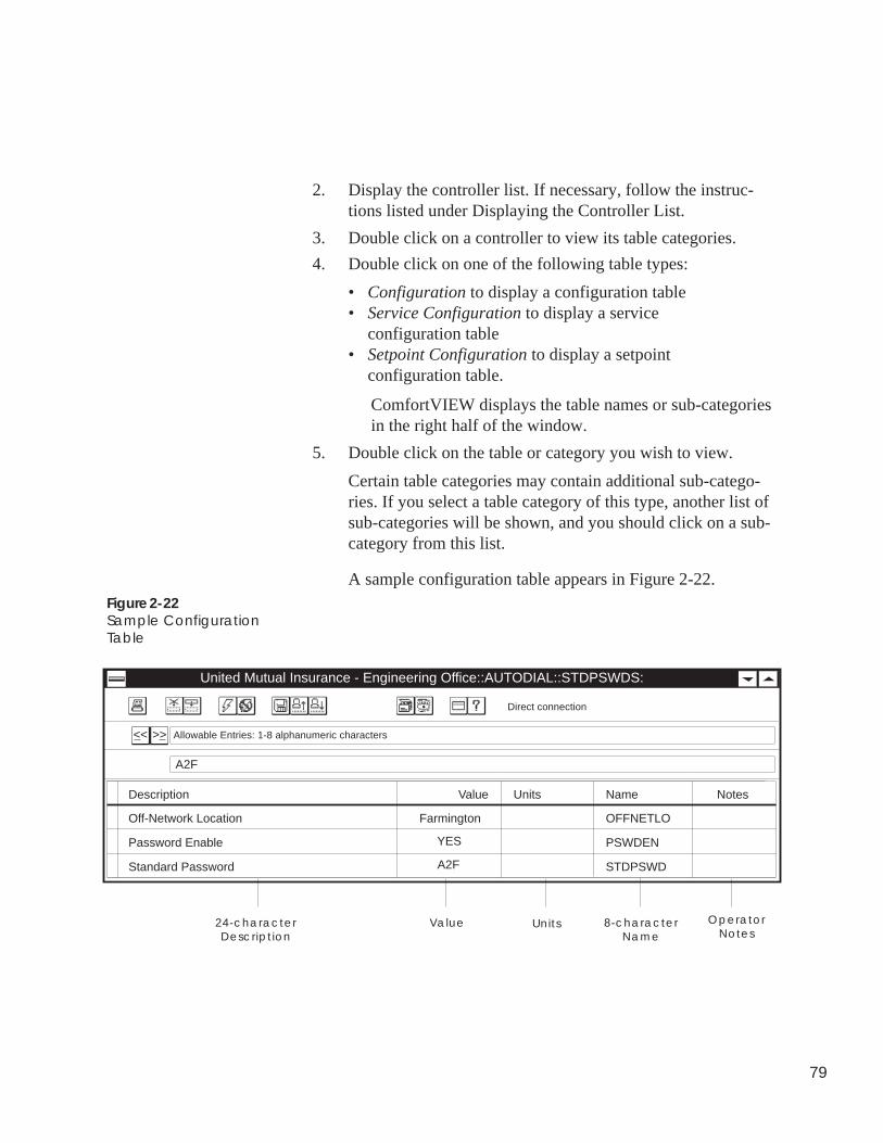
79
2. Display the controller list. If necessary, follow the instruc-tions listed under Displaying the Controller List.
3. Double click on a controller to view its table categories.
4. Double click on one of the following table types:
• Configuration to display a configuration table• Service Configuration to display a service
configuration table• Setpoint Configuration to display a setpoint
configuration table.
ComfortVIEW displays the table names or sub-categoriesin the right half of the window.
5. Double click on the table or category you wish to view.
Certain table categories may contain additional sub-catego-ries. If you select a table category of this type, another list ofsub-categories will be shown, and you should click on a sub-category from this list.
A sample configuration table appears in Figure 2-22.Figure 2-22Sample ConfigurationTable
United Mutual Insurance - Engineering Office::AUTODIAL::STDPSWDS:
Description Value Units Name Notes
A2F
Off-Network Location OFFNETLO
<< <<
Farmington
Password Enable PSWDENYES
Standard Password STDPSWDA2F
Value Units24-characterDescription
8-characterName
Direct connection
Allowable Entries: 1-8 alphanumeric characters
OperatorNotes
80
Like status display and maintenance tables, configuration tablewindows are similar to most popular spreadsheet applicationworksheets in that they consist of a rectangular grid of columns androws. The intersection of each column and row is a cell, the unit inwhich data is stored. The worksheets include the 24 characterdescription, value, units, eight character point name, and a notescolumn where you can enter an optional up to 48 character note.
You can move around the worksheet, adjust, hide and show columnsand rows, and modify point descriptions in the same manner aswhen displaying status display or maintenance tables. For instruc-tions, refer to Moving Around a Worksheet, Adjusting and HidingWorksheet Columns and Rows, and Modifying Point Descriptions.
While you are viewing a setpoint or occupancy configuration table,you can select the Window menu's Graphical command to displaythe table in a graphical format. Refer to the Window menu explana-tion that appears in this chapter's Carrier Network Manager Com-mand Summary section for further information on this displayformat.
Certain configuration tables contain multiple instances of table data.For example, the Autodial Gateway’s Secured Password Table. Ifthis is the case, the << and >> buttons display below the toolbar atthe beginning of the window’s status bar. Click on << to displaythe previous block of data or click on >> to display the next blockof data. Refer to Figure 2-22.
Use of a UT203 FID service configuration table is not compatiblewith use of any other FID table. Concurrent use of the serviceconfiguration table with any other UT203 FID table (by you or anyComfortVIEW operator) will result in the display of a Controller inuse or Controller currently locked message.
The Carrier Network Manager provides you with a short cut todisplay and modify a selected configuration entry's associatedconfiguration, maintenance, time schedule, or setpoint table whileyou are viewing a configuration table. To display a point's associ-ated tables, click on the Configure menu item followed by clickingon Configuration, Maintenance, Time Schedule, or Setpoint.ComfortVIEW will display the Table Jump Selection dialog box,which lists the controller's configuration, maintenance, time, orsetpoint schedule tables. If you select the Configuration or Mainte-
Configuration TableFormat
<< and >> Buttons
Viewing UT203 FIDService ConfigurationTables
Table Jumps fromConfiguration Tables
81
nance command from a magenta-shaded cell, ComfortVIEW willjump directly to the configuration entry's associated configuration ormaintenance table.
While you are viewing Comfort Controller configuration tables, theCarrier Network Manager provides you with a means to list thenames of all Comfort Controller objects that are using a selectedconfiguration point in their configuration.This feature is only avail-able for magenta-highlighted configuration points. To display apoint's associated objects, click on the Configure menu item fol-lowed by clicking on Reference tables. If desired, you can thendisplay a selected object's associated configuration or maintenancetable.
Alarm history tables are used to display a controller's alarm historydata. These tables exist in certain CCN controllers (such as ComfortControllers and some PICs).
Follow the steps below to display a controller’s alarm history tables.
1. Display the System Overview window and expand it todisplay the database’s CCNs and areas. If necessary, followthe instructions listed under Accessing the Carrier NetworkManager.
2. Display the controller list. If necessary, follow the instruc-tions listed under Displaying the Controller List.
3. Double click on a controller to view the table categories.
4. Double click on Alarm History.
ComfortVIEW displays the table name ALRMHIST in theright half of the window.
5. Double click on the ALRMHIST Table.
ComfortVIEW reads the controller's alarm history data anddisplays the Alarm History dialog box. Clicking on theRefresh button retrieves and displays the latest alarm data,Clicking on Close closes the dialog box.
Note: If the selected controller does not contain alarmhistory tables, the message This CCN element doesnot support the Alarm History feature will be dis-played.
Comfort ControllerReference Jumps
Viewing AlarmHistory Tables
82
ComfortVIEW's Bus Services function examines a CCN Bus andproduces a list of the bus's system elements and snapshot of activ-ity. You can use the Bus Services command to perform an updatepoll or cold call, or to produce a basic or detailed bus scan. For CCSthermostats and ComfortID boxes, you can also produce a systemsummary, which searches for and produces a system summary of allthe controllers that are part of a selected system.
Follow the instructions below to poll a CCN Bus:
1. Display the Carrier Network Manager's System Overviewwindow and expand it to display the database's CCNs. Ifnecessary, follow the instructions listed previously in thischapter under Accessing the Carrier Network Manager.
2. Click on the CCN or area that you wish to examine.
3. Click on the CCN Tools menu item and then click on BusServices.
Note: You may also perform this command by clicking onthe Bus Services toolbar button shown at left.
ComfortVIEW displays the Bus Services dialog box shownin Figure 2-22a.
4. Select the activity that you wish to perform (basic or detailedbus scan, update poll, or cold call.)
Different dialog box options will then become available,depending on the activity you have selected. For example,when performing an update poll or cold call, you can specifywhether to use ComfortVIEW's internal NDS function, anexternal NDS Module, or an automatically selected NDSmethod. When performing a bus scan, you can specify thebus number, range of elements, and whether to include onlyCCS and ComfortID devices.
5. Click on Run to close the Bus Services dialog box and per-form the specified activity, or on Close to exit the dialog boxwithout performing any activity.
Refer to Figure and Table 2-22a for additional information onthe options in this dialog box and Figures 2-22b, c, and d forsample basic, detailed, and system summary bus scan dis-plays.
Polling aCCN Bus
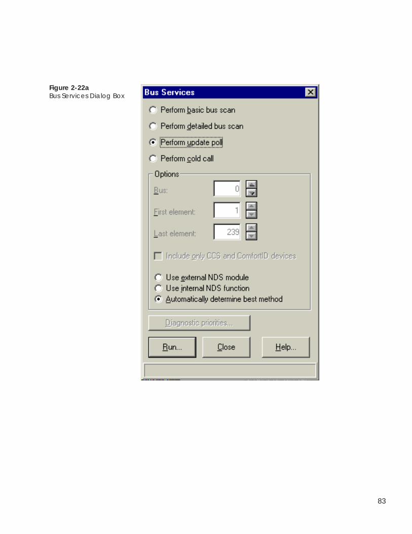
83
Figure 2-22aBus Services Dialog Box
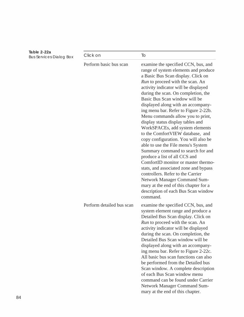
84
Table 2-22aBus Services Dialog Box Click on To
Perform basic bus scan examine the specified CCN, bus, andrange of system elements and producea Basic Bus Scan display. Click onRun to proceed with the scan. Anactivity indicator will be displayedduring the scan. On completion, theBasic Bus Scan window will bedisplayed along with an accompany-ing menu bar. Refer to Figure 2-22b.Menu commands allow you to print,display status display tables andWorkSPACEs, add system elementsto the ComfortVIEW database, andcopy configuration. You will also beable to use the File menu's SystemSummary command to search for andproduce a list of all CCS andComfortID monitor or master thermo-stats, and associated zone and bypasscontrollers. Refer to the CarrierNetwork Manager Command Sum-mary at the end of this chapter for adescription of each Bus Scan windowcommand.
Perform detailed bus scan examine the specified CCN, bus, andsystem element range and produce aDetailed Bus Scan display. Click onRun to proceed with the scan. Anactivity indicator will be displayedduring the scan. On completion, theDetailed Bus Scan window will bedisplayed along with an accompany-ing menu bar. Refer to Figure 2-22c.All basic bus scan functions can alsobe performed from the Detailed busScan window. A complete descriptionof each Bus Scan window menucommand can be found under CarrierNetwork Manager Command Sum-mary at the end of this chapter.
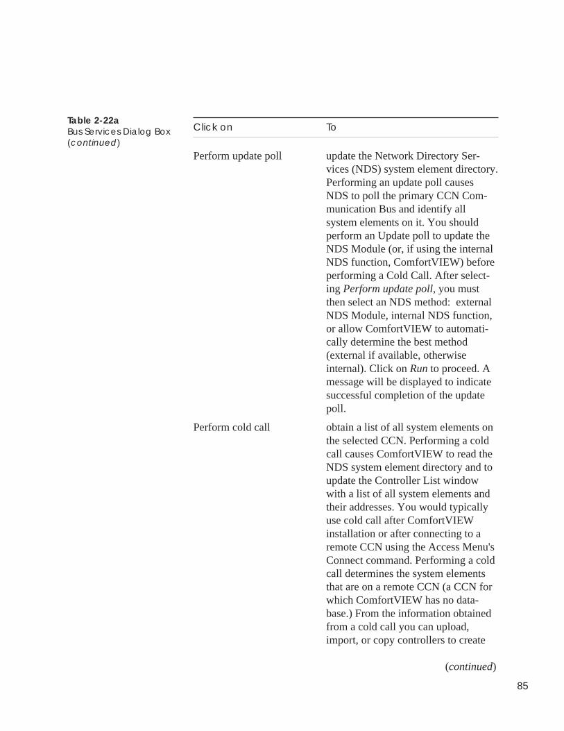
85
Click on To
Perform update poll update the Network Directory Ser-vices (NDS) system element directory.Performing an update poll causesNDS to poll the primary CCN Com-munication Bus and identify allsystem elements on it. You shouldperform an Update poll to update theNDS Module (or, if using the internalNDS function, ComfortVIEW) beforeperforming a Cold Call. After select-ing Perform update poll, you mustthen select an NDS method: externalNDS Module, internal NDS function,or allow ComfortVIEW to automati-cally determine the best method(external if available, otherwiseinternal). Click on Run to proceed. Amessage will be displayed to indicatesuccessful completion of the updatepoll.
Perform cold call obtain a list of all system elements onthe selected CCN. Performing a coldcall causes ComfortVIEW to read theNDS system element directory and toupdate the Controller List windowwith a list of all system elements andtheir addresses. You would typicallyuse cold call after ComfortVIEWinstallation or after connecting to aremote CCN using the Access Menu'sConnect command. Performing a coldcall determines the system elementsthat are on a remote CCN (a CCN forwhich ComfortVIEW has no data-base.) From the information obtainedfrom a cold call you can upload,import, or copy controllers to create
(continued)
Table 2-22aBus Services Dialog Box(continued)
86
Table 2-22aBus Services Dialog Box(continued)
Click on To
the database for your CCN. Afterselecting Perform cold call you mustselect the NDS method (see updatepoll above) and then click on Run.The CCN Areas dialog box will bedisplayed (if in Step 2 an area was notselected). Select an area in which toplace the system elements and clickon OK. ComfortVIEW will present aconfirmation dialog box asking if youwish to perform an update poll.Typically, before performing a coldcall, you should update the NDSsystem element directory. Click onYes to do so. An activity indicatordisplays during the update poll andcold call processes. On completion ofthe cold call, the Controller Listwindow will be displayed. The namesand addresses of all controllers in theNDS system element directory will bedisplayed in the Controller List.
Note: Cold call does not update theComfortVIEW database. It onlyincludes the name and address ofcontrollers in the Controller Listwindow. Controllers for whichComfortVIEW has no database infor-mation will appear dimmed. You mustuse the Configure menu's Upload,Import, or Copy commands to add thecontrollers to the database.
Bus enter the number of the CCN Bus forwhich you wish to perform a basic ordetailed bus scan.
(continued)
87
Click on To
First element enter the lowest system elementaddress on the specified bus. The busscan will examine those systemelements beginning with this elementnumber up to and ending with theelement number specified in the Lastelement.
Last element enter the highest system elementaddress on the specified bus.
Include only CCS andComfortID devices scan only CCS and ComfortID system
elements versus all CCN systemelements on the specified bus.
Use external NDS Module perform the update poll or cold callusing an NDS Module that is physi-cally connected to the CCN Bus.
Use internal NDS function perform the update poll or cold callus-ing ComfortVIEW's internal NDSfunction.
Automatically determinebest method use an external NDS Module, if
found, to perform the update poll. Ifan external NDS Module is not found,ComfortVIEW will use its internalNDS function.
Diagnostic priorities if desired, assign a high priority NDSdiagnostic routine scan rate to CCNsystem elements that are displayed inthe recently performed cold call'sController List. This will causeComfortVIEW internal diagnosticpolling to take place every 60 minutes
(continued)
Table 2-22aBus Services Dialog Box(continued)
88
Table 2-22aBus Services Dialog Box(continued)
Click on To
and whenever ComfortVIEW isstarted (i.e. during PC boot) versusevery 6 hours. ComfortVIEW willdisplay the Diagnostic Prioritiesdialog box. Those elements that arecurrently selected for high priorityscanning will be highlighted. Selectany other elements and click on OK.The Diagnostic routine scans all CCNBuses and checks for communicationand clock errors. The routine gener-ates alarms and alerts that you canview using the Alarm Manager appli-cation.
Run close the dialog box and perform thespecified operation (update poll, coldcall, or bus scan.)
Close exit the dialog box without perform-ing any activity. Any changes madeare not saved.
Help display help information.
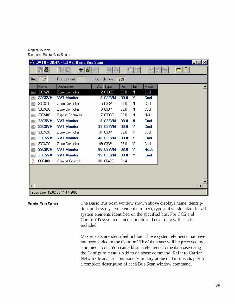
89
Figure 2-22bSample Basic Bus Scan
The Basic Bus Scan window shown above displays name, descrip-tion, address (system element number), type and version data for allsystem elements identified on the specified bus. For CCS andComfortID system elements, mode and error data will also beincluded.
Master stats are identified in blue. Those system elements that havenot been added to the ComfortVIEW database will be preceded by a"dimmed" icon. You can add such elements to the database usingthe Configure menu's Add to database command. Refer to CarrierNetwork Manager Command Summary at the end of this chapter fora complete description of each Bus Scan window command.
Basic Bus Scan
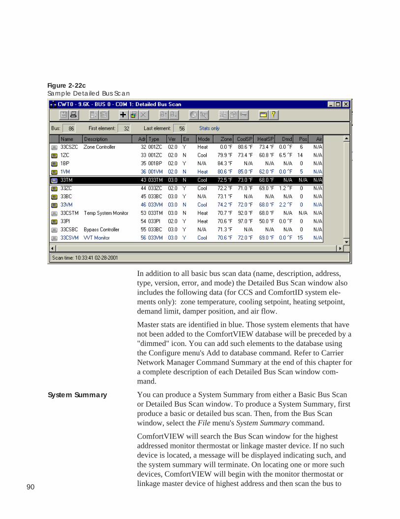
90
Figure 2-22cSample Detailed Bus Scan
In addition to all basic bus scan data (name, description, address,type, version, error, and mode) the Detailed Bus Scan window alsoincludes the following data (for CCS and ComfortID system ele-ments only): zone temperature, cooling setpoint, heating setpoint,demand limit, damper position, and air flow.
Master stats are identified in blue. Those system elements that havenot been added to the ComfortVIEW database will be preceded by a"dimmed" icon. You can add such elements to the database usingthe Configure menu's Add to database command. Refer to CarrierNetwork Manager Command Summary at the end of this chapter fora complete description of each Detailed Bus Scan window com-mand.
You can produce a System Summary from either a Basic Bus Scanor Detailed Bus Scan window. To produce a System Summary, firstproduce a basic or detailed bus scan. Then, from the Bus Scanwindow, select the File menu's System Summary command.
ComfortVIEW will search the Bus Scan window for the highestaddressed monitor thermostat or linkage master device. If no suchdevice is located, a message will be displayed indicating such, andthe system summary will terminate. On locating one or more suchdevices, ComfortVIEW will begin with the monitor thermostat orlinkage master device of highest address and then scan the bus to
Detailed Bus Scan
System Summary
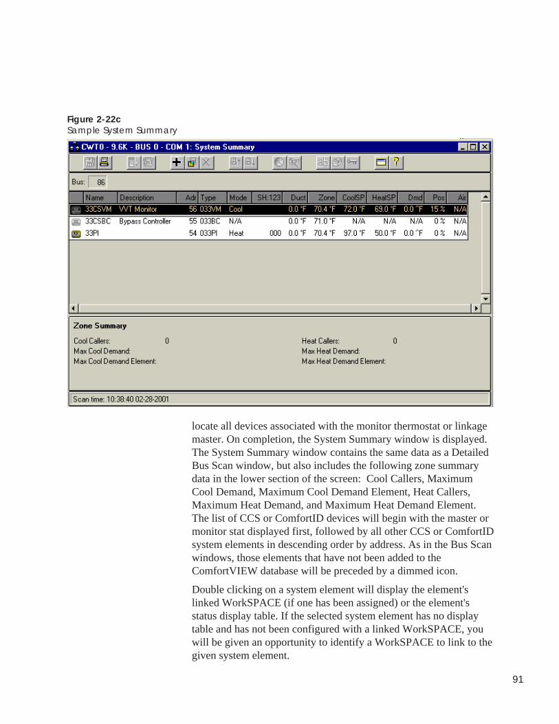
91
Figure 2-22cSample System Summary
locate all devices associated with the monitor thermostat or linkagemaster. On completion, the System Summary window is displayed.The System Summary window contains the same data as a DetailedBus Scan window, but also includes the following zone summarydata in the lower section of the screen: Cool Callers, MaximumCool Demand, Maximum Cool Demand Element, Heat Callers,Maximum Heat Demand, and Maximum Heat Demand Element.The list of CCS or ComfortID devices will begin with the master ormonitor stat displayed first, followed by all other CCS or ComfortIDsystem elements in descending order by address. As in the Bus Scanwindows, those elements that have not been added to theComfortVIEW database will be preceded by a dimmed icon.
Double clicking on a system element will display the element'slinked WorkSPACE (if one has been assigned) or the element'sstatus display table. If the selected system element has no displaytable and has not been configured with a linked WorkSPACE, youwill be given an opportunity to identify a WorkSPACE to link to thegiven system element.
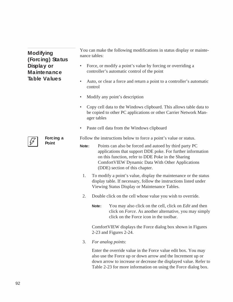
92
You can make the following modifications in status display or mainte-nance tables:
• Force, or modify a point’s value by forcing or overriding acontroller’s automatic control of the point
• Auto, or clear a force and return a point to a controller’s automaticcontrol
• Modify any point’s description
• Copy cell data to the Windows clipboard. This allows table data tobe copied to other PC applications or other Carrier Network Man-ager tables
• Paste cell data from the Windows clipboard
Follow the instructions below to force a point’s value or status.
Note: Points can also be forced and autoed by third party PCapplications that support DDE poke. For further informationon this function, refer to DDE Poke in the SharingComfortVIEW Dynamic Data With Other Applications(DDE) section of this chapter.
1. To modify a point’s value, display the maintenance or the statusdisplay table. If necessary, follow the instructions listed underViewing Status Display or Maintenance Tables.
2. Double click on the cell whose value you wish to override.
Note: You may also click on the cell, click on Edit and thenclick on Force. As another alternative, you may simplyclick on the Force icon in the toolbar.
ComfortVIEW displays the Force dialog box shown in Figures2-23 and Figures 2-24.
3. For analog points:
Enter the override value in the Force value edit box. You mayalso use the Force up or down arrow and the Increment up ordown arrow to increase or decrease the displayed value. Refer toTable 2-23 for more information on using the Force dialog box.
Modifying(Forcing) StatusDisplay orMaintenanceTable Values
Forcing aPoint
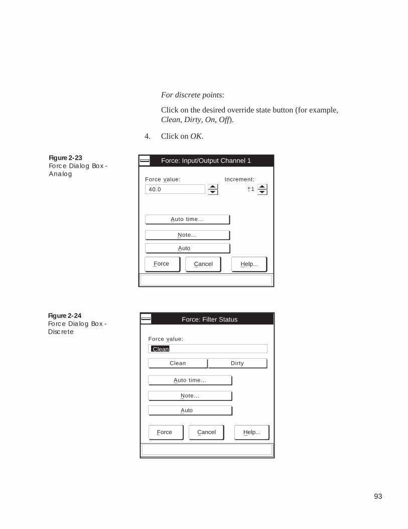
93
For discrete points:
Click on the desired override state button (for example,Clean, Dirty, On, Off).
4. Click on OK.
Figure 2-23Force Dialog Box -Analog
Figure 2-24Force Dialog Box -Discrete
Force value:
Force: Input/Output Channel 1
Increment:
1+-40.0
Auto time...
Note...
Force Cancel Help...
Auto
Clean Dirty
Force value:
Clean
Force Cancel Help...
Auto time...
Force: Filter Status
Note...
Auto
94
The word Supervisor (for local ComfortVIEW forces) orRemote Monitor (for remote ComfortVIEW forces) appears inthe points status column to indicate that a ComfortVIEWforce is in effect.
Follow the instructions below to clear a force and return the point tothe controller’s automatic control.
1. Display the status display or maintenance table. If necessary,follow the instructions listed under Viewing Status Display orMaintenance Tables.
2. Click on the cell whose force you wish to clear.
3. Click on Edit and then click on Auto.
Note: You may also perform this command by clicking onthe Auto icon in the toolbar or by double clicking onthe cell and, in the Force dialog box, clicking onAuto.
The force clears and the point returns to the controller’s automaticcontrol.
Note: If more than one force exists on a point, perform Steps 2and 3 until all force statuses are removed.
Click on To
the override state button(Example: Clean, Dirty,On, Off) select the desired override state
(for discrete points only).
the Force value edit box enter the desired override value(for analog points only).
the Increment: up ordown arrow select the increase or decrease granu-
larity (For example, .1, 1, 100, 1000)
(continued)
Autoing a Point
Table 2-23Force Dialog Box
95
Click on To
the Force value up ordown arrow increase or decrease the override value
for analog points.
Auto time indicate the time and date to removethe force. This option is only availablefor those PIC controllers that supporta force expiration. ComfortVIEWdisplays the Auto Time and Datedialog box. Click on the day of themonth and enter the time to removethe force. To change the month, clickon the scroll bar’s down or up arrow.Click on OK to close the dialog boxand save your settings.
Note add an operator note in the Forcedialog box. The Force Note dialogbox displays. In the Force note box,enter a new or edit the existing note.Click on OK to save the changes orclick on Cancel to exit without savingchanges. Force notes appear in theSystem Activity report.
Auto remove any current force that may beon the point.
Force transmit the force to the point.
Cancel exit the dialog box and restore theprevious settings. Any changes madeare not saved.
Help display help information.
Table 2-23Force Dialog Box(continued)
96
If desired, you can modify any point’s description.
Note: These instructions do not apply to UT203 FIDs or Com-fort Controllers. To modify point descriptions for thesetwo system elements, refer to Configuring UT203 FIDs orConfiguring Comfort Controllers, which appear later inthis Carrier Network Manager chapter.
1. Click on the description cell and type the new name.
The text appears in the cell and in the edit bar, which islocated below the window’s status bar.
2. Press Enter or click on the edit bar’s enter icon to enter thechange.
Note: Clicking on the edit bar’s cancel icon cancels thechange.
3. Click on the Configure menu item and then click on Save.
If desired, you can copy selected cell data to the Windows clip-board. You can also paste clipboard data to a selected cell.
To Copy Cell Data:
1. Click on the cell or drag select multiple cells that you wish tocopy.
2. Click on the Edit menu item and then click on Copy.
Note: You may also perform this command by clicking onthe Copy icon in the toolbar.
The selected cell’s data will be copied to the Windows clip-board. You can now paste this data into another CarrierNetwork Manager table or to another third party softwareapplication.
To Paste Cell Data from the Windows clipboard:
1. Display the table to which you wish to paste.
2. Click on the cell into which you wish to paste.
3. Click on the Edit menu item and then click on Paste.
Note: You may also perform this command by clicking onthe Paste icon in the toolbar.
To Modify PointDescriptions
To Copy and PasteCell Data
97
The selected cell’s data will be copied from the Windowsclipboard to the selected cell.
If you are attempting to paste data into a protected cell or areattempting to paste incompatible data, an error message boxdisplays. Click on OK to close the message box.
Follow the instructions below to modify, download, and writemodified configuration table values to the ComfortVIEW database.
Note: ComfortVIEW now includes a dynamic-link library(DLL), which can be used to provide third party access toCCN time schedule and setpoint configuration tables. ThisDLL (CWACCESS.DLL) exposes read and write func-tionality, which can be utilized to create your own customsoftware applications. For further information and instruc-tions on using this DLL, refer to Appendix B —CWACCESS DLL.
1. Display the configuration table. If necessary, follow theinstructions listed under Viewing Configuration Tables.
2. For analog value or text entry cells:
Click on the cell you wish to change and type the new value.
Note: To modify cells containing point names, the CapsLock key must be enabled.
For discrete values:
Click on the value cell you wish to change and press thespace bar to toggle the discrete state.
The value appears in the cell and in the edit bar, which islocated below the window’s status bar.
3. Press Enter or click on the edit bar’s enter icon to enter thechange.
4. Click on Configure and then click on Save if you wish to savethe new value in the ComfortVIEW database, or,
if you wish to cancel, click on Window and then click onRefresh to refresh the window with the most recent data thathas been written to the database.
Note: You may also perform these commands by clickingon the Save or the Refresh icon in the toolbar.
ModifyingConfigurationTable Values
98
5. Click on Configuration and then click on Download if you wish tosend the new value to the controller.
Note: You may also perform this command by clicking on theDownload icon in the toolbar.
If ComfortVIEW displays the message CCN CurrentlyLocked or CCN Is In Use, you have attempted to downloada controller table that is currently being accessed by you oranother ComfortVIEW operator. Attempt the downloadagain when the controller is available.
For certain types of controllers, the drag and drop feature is available toexpedite the entry of configuration data. This feature allows you to use theWindows drag and drop technique to copy data from a points status,maintenance, or time schedule table to the configuration table you aremodifying. The availability of drag and drop is indicated by the presenceof green coloring on a configuration decision’s description text. Thistechnique can be a tremendous time saver in configuring controllers suchas the Data Collection Option.
Follow the steps below to use drag and drop:
1. Display the source and destination tables. You can use the Cascadeor Tile command in the Window menu to re-arrange windows.
2. Position the mouse pointer on the Value cell for the point that youwish to copy.
3. Press and hold down the Ctrl key.
4. Press and hold down the mouse button and drag the mouse to re-position it on the Value cell for the configuration table point thatyou wish to copy to.
A small square icon appears next to the mouse pointer. A plus signappears inside the icon to indicate you are copying.
5. Release the Ctrl key and then release the mouse button when thesquare is positioned on the Value cell you are copying to.
The configuration table window updates with configuration data automati-cally completed for you.
Drag and Drop
99
A Drag and Drop Example:
You wish to configure the Data Collection Option to collect runtimedata from the Supply Fan Status point in the 39N Air Handler.
To collect runtime data, you must configure the following tables:
• The Runtime Configuration Table in the 39N Air Handler• The Runtime (RUNTM01S) Configuration Table in the Data
Collection Option
Drag and drop saves you a significant amount of configuration timeby automatically completing a large portion of the configurationtable data entry for you.
Follow the steps below to use drag and drop to automatically com-plete the configuration required in this example.
1. Simultaneously display the 39N Baseunit StatusDisplay Table, the 39N Runtime Configuration Table,and the Data Collection Option Runtime ConfigurationTable.
2. Use the drag and drop technique described in Steps 2to 4 under Drag and Drop to automatically complete39N Runtime Configuration Table data entry. To dothis, copy the 39N Baseunit Status Display Table’sSupply Fan Status point to the Runtime 1 Point Namedecision in the 39N Runtime Configuration Table.
ComfortVIEW automatically fills in the point nameand point type configuration for you.
3. Now you can use drag and drop to automaticallycomplete the Data Collection Option Runtime Configuration Table data entry. To do this, copy the 39NRuntime Configuration Table’s Runtime 1 Point Namedecision to the Runtime #1 Contlr Name decision inthe Data Collection Option’s Runtime ConfigurationTable, RUNTM01S.
ComfortVIEW automatically fills in all requiredconfiguration decisions for you. Refer to Figure 2-25.
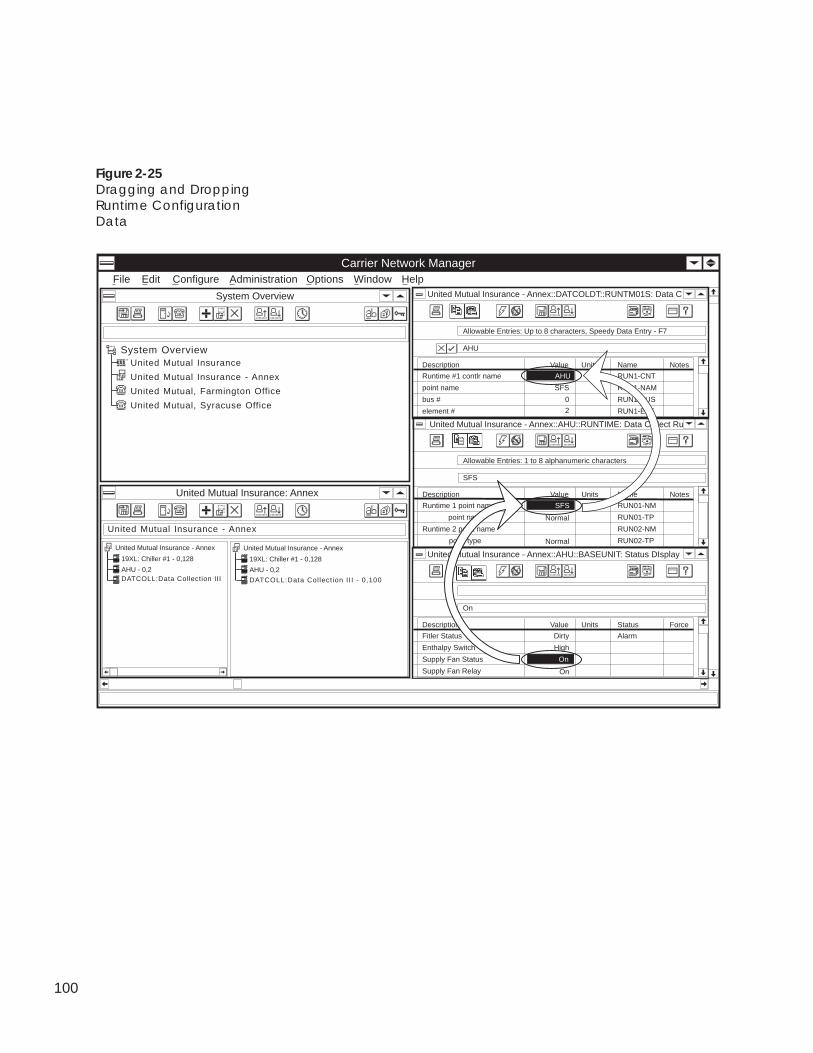
100
Figure 2-25Dragging and DroppingRuntime ConfigurationData
Carrier Network Manager
United Mutual Insurance: Annex
United Mutual Insurance - Annex
System Overview
United Mutual Insurance
United Mutual Insurance - Annex
United Mutual, Farmington Office
United Mutual, Syracuse Office
System Overview
AdministrationFile Edit Configure Options HelpWindow
Description Value Units Name Notes
Runtime 1 point name RUN01-NM
point name Normal RUN01-TP
Runtime 2 point name RUN02-NM
point type Normal RUN02-TP
SFS
United Mutual Insurance - Annex::AHU::RUNTIME: Data Collect Ru
Allowable Entries: 1 to 8 alphanumeric characters
SFS
Description Value Units Status Force
Fitler Status Alarm
Enthalpy Switch High
Supply Fan Status
Supply Fan Relay On
On
United Mutual Insurance - Annex::AHU::BASEUNIT: Status DIsplay
Dirty
On
19XL: Chiller #1 - 0,128
United Mutual Insurance - Annex
DATCOLL:Data Collection IIIAHU - 0,2
19XL: Chiller #1 - 0,128
United Mutual Insurance - Annex
DATCOLL:Data Collect ion II I - 0,100
AHU - 0,2
Description Value Units Name Notes
Runtime #1 contlr name RUN1-CNT
point name SFS RUN1-NAM
bus # 0 RUN1-BUS
element # 2 RUN1-ELE
AHU
United Mutual Insurance - Annex::DATCOLDT::RUNTM01S: Data C
Allowable Entries: Up to 8 characters, Speedy Data Entry - F7
AHU
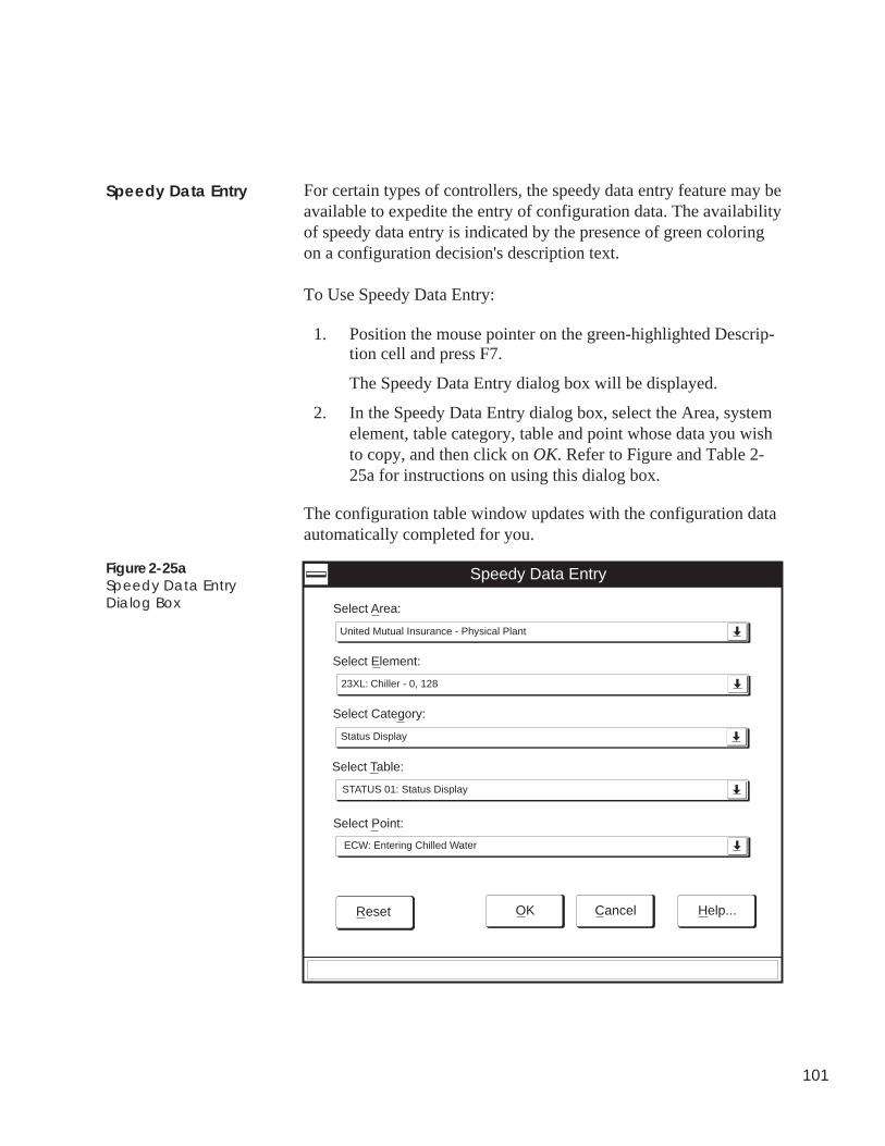
101
Speedy Data Entry
Speedy Data Entry
Select Area:
Cancel Help...
Select Element:
Select Category:
Select Table:
Select Point:
United Mutual Insurance - Physical Plant
23XL: Chiller - 0, 128
Status Display
STATUS 01: Status Display
ECW: Entering Chilled Water
OKReset
Figure 2-25aSpeedy Data EntryDialog Box
For certain types of controllers, the speedy data entry feature may beavailable to expedite the entry of configuration data. The availabilityof speedy data entry is indicated by the presence of green coloringon a configuration decision's description text.
To Use Speedy Data Entry:
1. Position the mouse pointer on the green-highlighted Descrip-tion cell and press F7.
The Speedy Data Entry dialog box will be displayed.
2. In the Speedy Data Entry dialog box, select the Area, systemelement, table category, table and point whose data you wishto copy, and then click on OK. Refer to Figure and Table 2-25a for instructions on using this dialog box.
The configuration table window updates with the configuration dataautomatically completed for you.
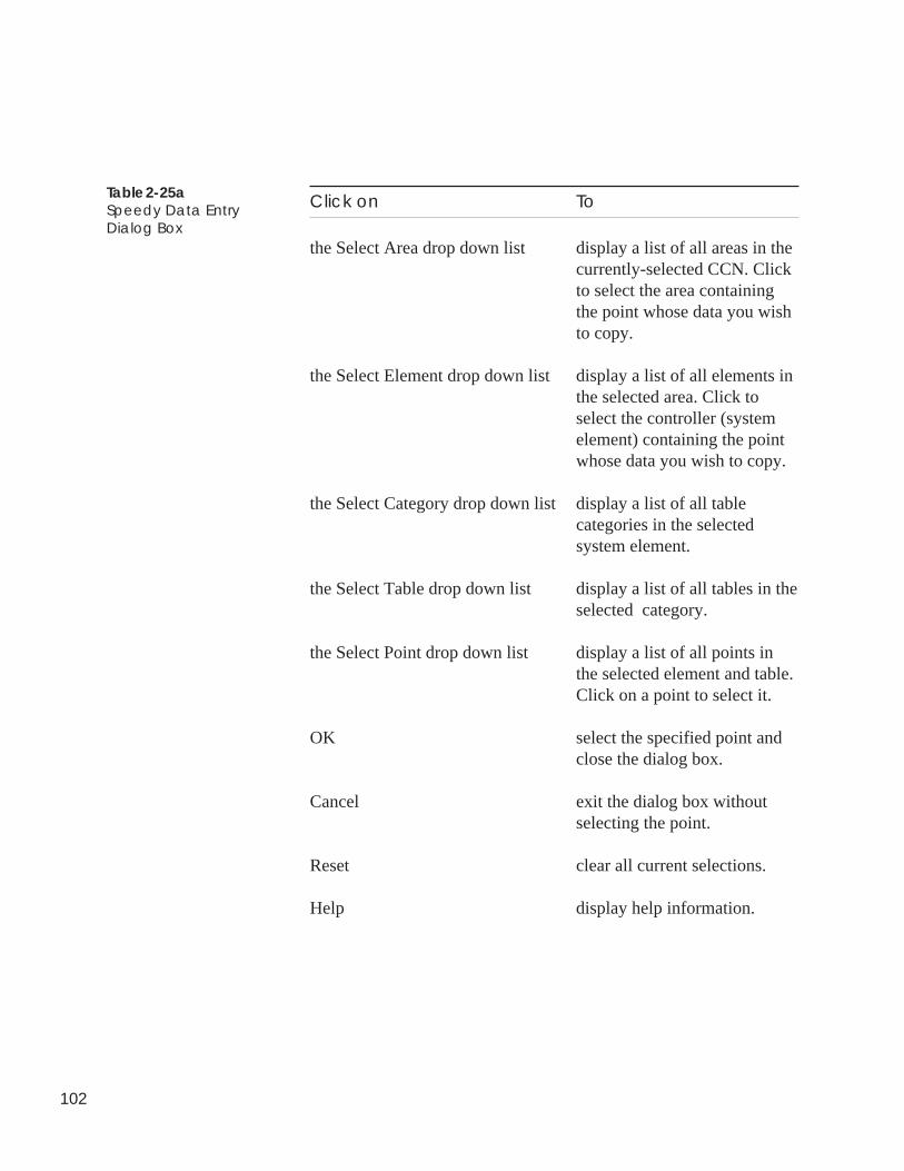
102
Table 2-25aSpeedy Data EntryDialog Box
Click on To
the Select Area drop down list display a list of all areas in thecurrently-selected CCN. Clickto select the area containingthe point whose data you wishto copy.
the Select Element drop down list display a list of all elements inthe selected area. Click toselect the controller (systemelement) containing the pointwhose data you wish to copy.
the Select Category drop down list display a list of all tablecategories in the selectedsystem element.
the Select Table drop down list display a list of all tables in theselected category.
the Select Point drop down list display a list of all points inthe selected element and table.Click on a point to select it.
OK select the specified point andclose the dialog box.
Cancel exit the dialog box withoutselecting the point.
Reset clear all current selections.
Help display help information.
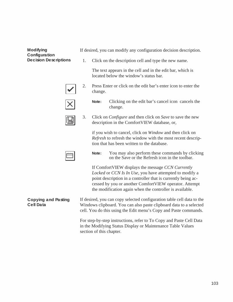
103
ModifyingConfigurationDecision Descriptions
Copying and PastingCell Data
If desired, you can modify any configuration decision description.
1. Click on the description cell and type the new name.
The text appears in the cell and in the edit bar, which islocated below the window’s status bar.
2. Press Enter or click on the edit bar’s enter icon to enter thechange.
Note: Clicking on the edit bar’s cancel icon cancels thechange.
3. Click on Configure and then click on Save to save the newdescription in the ComfortVIEW database, or,
if you wish to cancel, click on Window and then click onRefresh to refresh the window with the most recent descrip-tion that has been written to the database.
Note: You may also perform these commands by clickingon the Save or the Refresh icon in the toolbar.
If ComfortVIEW displays the message CCN CurrentlyLocked or CCN Is In Use, you have attempted to modify apoint description in a controller that is currently being ac-cessed by you or another ComfortVIEW operator. Attemptthe modification again when the controller is available.
If desired, you can copy selected configuration table cell data to theWindows clipboard. You can also paste clipboard data to a selectedcell. You do this using the Edit menu’s Copy and Paste commands.
For step-by-step instructions, refer to To Copy and Paste Cell Datain the Modifying Status Display or Maintenance Table Valuessection of this chapter.
104
ModifyingTable Names
and Descriptions
ComfortVIEW gives you the capability to modify all controllertable descriptions and Loadshed and Occupancy table names. Notethat you can also modify Comfort Controller table names anddescriptions. To do this, however, you must follow the instructionsin the Configuring Comfort Controllers section of this chapter.
Table names and descriptions appear in the controller list and astable headers throughout ComfortVIEW. You would typicallymodify table descriptions if you wished to customize your control-ler list displays. You would modify Loadshed and Occupancy tablenames to maintain a one to one correspondence between the tablenames in the option and the table names in the equipment that theoption affects.
Note: Exercise caution when modifying Loadshed and Occu-pancy Option table names — modify only the numbersthat appear in the table name. Do not modify other char-acters in the name. For example, you can change the nameof the Loadshed Option’s LDSHD01E Table to a namesuch as LDSHD02E. LODSH02E, however, would be aninvalid modification.
Follow the steps below to change the name or description of acontroller’s configuration tables:
1. Display the Controller List window. If necessary, follow theinstructions listed under Displaying the Controller List.
2. Double click on a controller to views its table types.
3. Double click on the type of table whose name or descriptionyou wish to modify: Status Display, Maintenance Display,Configuration, Service Configuration, Setpoint Configura-tion.
ComfortVIEW displays the table names in the right half ofthe window.
4. Click to select the table whose name or description you wishto modify.
Certain tables may contain additional tables. If you select atable of this type, another list of tables will be shown and youshould double click on a table from this list.
5. Click on Configure and then click on Modify.
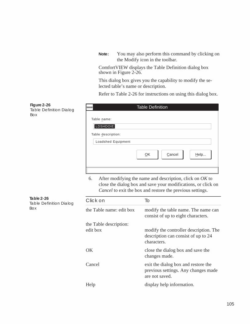
105
Note: You may also perform this command by clicking onthe Modify icon in the toolbar.
ComfortVIEW displays the Table Definition dialog boxshown in Figure 2-26.
This dialog box gives you the capability to modify the se-lected table’s name or description.
Refer to Table 2-26 for instructions on using this dialog box.
Table Definition
Table name:
LDSHDOIE
Table description:
Loadshed Equipment
OK Cancel Help...
Figure 2-26Table Definition DialogBox
6. After modifying the name and description, click on OK toclose the dialog box and save your modifications, or click onCancel to exit the box and restore the previous settings.
Click on To
the Table name: edit box modify the table name. The name canconsist of up to eight characters.
the Table description:edit box modify the controller description. The
description can consist of up to 24characters.
OK close the dialog box and save thechanges made.
Cancel exit the dialog box and restore theprevious settings. Any changes madeare not saved.
Help display help information.
Table 2-26Table Definition DialogBox
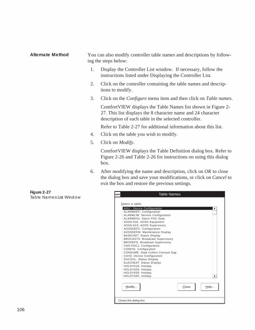
106
You can also modify controller table names and descriptions by follow-ing the steps below:
1. Display the Controller List window. If necessary, follow theinstructions listed under Displaying the Controller List.
2. Click on the controller containing the table names and descrip-tions to modify.
3. Click on the Configure menu item and then click on Table names.
ComfortVIEW displays the Table Names list shown in Figure 2-27. This list displays the 8 character name and 24 characterdescription of each table in the selected controller.
Refer to Table 2-27 for additional information about this list.
4. Click on the table you wish to modify.
5. Click on Modify.
ComfortVIEW displays the Table Definition dialog box. Refer toFigure 2-26 and Table 2-26 for instructions on using this dialogbox.
6. After modifying the name and description, click on OK to closethe dialog box and save your modifications, or click on Cancel toexit the box and restore the previous settings.
Alternate Method
AHU - Device Configuration
Table Names
Close Help...
Select a table:
Closes this dialog box
Modify...
ALARMDEF: ConfigurationALARMLIM: Service ConfigurationALARMSO1: Alarm POC DataAOSS-01E: AOSS EquipmentAOSS-01S: AOSS SupervisoryAOSSDEFC: ConfigurationAOSSDEFM: Maintenance DisplayBASEUNIT: Status DIsplayBROCASTS: Broadcast SupervisoryBRODEFS: Broadcast SupervisoryCNS-POC1: ConfigurationCONFIG: ConfigurationCONSUME: Data Collect Consum EqpCtlrID: Device ConfigurationDXCOOL: Status DisplayELECHEAT: Status DIsplayHOLDY01S: HolidayHOLDY02S: HolidayHOLDY03S: HolidayHOLDY04S: Holiday
Figure 2-27Table Names List Window
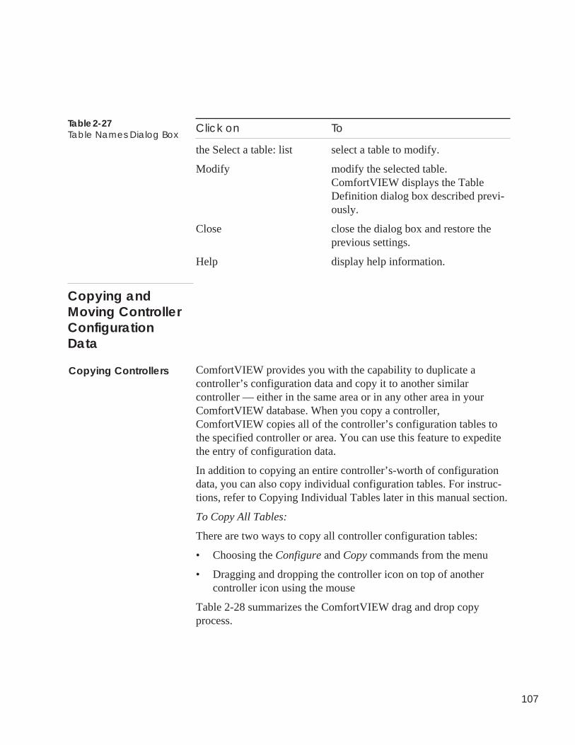
107
Table 2-27Table Names Dialog Box
Click on To
the Select a table: list select a table to modify.
Modify modify the selected table.ComfortVIEW displays the TableDefinition dialog box described previ-ously.
Close close the dialog box and restore theprevious settings.
Help display help information.
ComfortVIEW provides you with the capability to duplicate acontroller’s configuration data and copy it to another similarcontroller — either in the same area or in any other area in yourComfortVIEW database. When you copy a controller,ComfortVIEW copies all of the controller’s configuration tables tothe specified controller or area. You can use this feature to expeditethe entry of configuration data.
In addition to copying an entire controller’s-worth of configurationdata, you can also copy individual configuration tables. For instruc-tions, refer to Copying Individual Tables later in this manual section.
To Copy All Tables:
There are two ways to copy all controller configuration tables:
• Choosing the Configure and Copy commands from the menu
• Dragging and dropping the controller icon on top of anothercontroller icon using the mouse
Table 2-28 summarizes the ComfortVIEW drag and drop copyprocess.
Copying andMoving ControllerConfigurationData
Copying Controllers
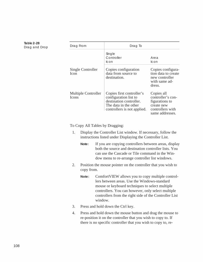
108
Table 2-28Drag and Drop Drag From Drag To
SingleController AreaIcon Icon
Single Controller Copies configuration Copies configura-Icon data from source to tion data to create
destination. new controllerwith same ad-dress.
Multiple Controller Copies first controller’s Copies allIcons configuration list to controller’s con-
destination controller. figurations toThe data in the other create newcontrollers is not applied. controllers with
same addresses.
To Copy All Tables by Dragging:
1. Display the Controller List window. If necessary, follow theinstructions listed under Displaying the Controller List.
Note: If you are copying controllers between areas, displayboth the source and destination controller lists. Youcan use the Cascade or Tile command in the Win-dow menu to re-arrange controller list windows.
2. Position the mouse pointer on the controller that you wish tocopy from.
Note: ComfortVIEW allows you to copy multiple control-lers between areas. Use the Windows-standardmouse or keyboard techniques to select multiplecontrollers. You can however, only select multiplecontrollers from the right side of the Controller Listwindow.
3. Press and hold down the Ctrl key.
4. Press and hold down the mouse button and drag the mouse tore-position it on the controller that you wish to copy to. Ifthere is no specific controller that you wish to copy to, re-
109
position the mouse on the area icon. This will create a newcontroller in the area.
A small square icon appears next to the mouse pointer. A plussign appears inside the icon to indicate that you are copying,not moving, the controller to another area.
5. Release the mouse button and then release the Ctrl key whenthe square is positioned on the controller or area you arecopying to.
ComfortVIEW displays a dialog box asking for confirmationbefore copying the controller.
6. Click on Yes to complete the copy or click on No to prevent thecopy from taking place. If you have selected multiple control-lers and wish to copy all, click on Yes to All. Clicking onCancel aborts the copy. If you have selected multiple control-lers and wish to step through the copies one by one, click onYes.
A Copy Status Box is displayed during the copy. This boxdisplays each table and block number as it is being copied.Clicking on Abort will stop the copy.
To Copy All Tables with the Configure Menu’s Copy Command:
1. Display the Controller List window. If necessary, follow theinstructions listed under Displaying the Controller List.
2. Click on the controller that you wish to configure (copy from).
Note: ComfortVIEW allows you to copy multiple control-lers. Use the Windows-standard mouse or keyboardtechniques to select multiple controllers. You canhowever, only select multiple controllers from theright side of the Controller List window.
3. Click on the Configure menu item and then click on Copy.
ComfortVIEW displays the Areas dialog box.
4. In the Select target area: list, click on the area containing thecontroller whose tables you wish to copy to, and then click onOK.
ComfortVIEW displays the CCN Elements dialog box.
110
5. Click on the CCN element whose tables you wish to copy to,and then click on OK.
A confirmation dialog box displays re-confirming the sourceand destination controllers.
6. Click on Yes to complete the copy, or on No to prevent the copy.If you have selected multiple controllers and wish to copy all,click on Yes to All.
A Copy Status Box is displayed during the copy. This boxdisplays each table and block number as it is being copied.Clicking on Abort will stop the copy.
To Copy and Paste Individual Tables:
There are three ways to copy individual tables:
• Dragging and dropping the table icon on top of another table iconusing the mouse
• Choosing the Configure and Copy commands from the menu
• Cutting and pasting selected configuration table cells.
To Copy Individual Tables by Dragging:
1. Display the Controller List window and expand it to display theconfiguration table names. If necessary, follow the instructionslisted under Displaying the Controller List and Viewing Con-figuration Tables.
Note: If you are copying tables between areas, display boththe source and destination controller lists. You can usethe Cascade or Tile command in the Window menu tore-arrange controller list windows.
2. Position the mouse pointer on the table that you wish to copyfrom.
3. Press and hold down the mouse button and drag the mouse to re-position it on the table that you wish to copy to.
4. Release the mouse button when the square is positioned on thetable you are copying to.
ComfortVIEW displays a dialog box asking for confirmationbefore copying the table.
111
5. Click on Yes to complete the copy or click on No to preventthe copy from taking place. Clicking on Cancel aborts thecopy.
To Copy Individual Tables with the Configure Menu’s Copy Com-mand:
1. Display the Controller List window and expand it to displaythe configuration table names. If necessary, follow the in-structions listed under Displaying the Controller List andViewing Configuration Tables.
2. Click on the table that you wish to configure (copy from).
3. Click on the Configure menu item and then click on Copy.
ComfortVIEW displays the Areas dialog box.
4. In the Select target area: list, click on the area containing thecontroller whose tables you wish to copy to, and then clickon OK.
ComfortVIEW displays the CCN Elements dialog box.
5. Click on the CCN element whose tables you wish to copy to,and then click on OK.
ComfortVIEW display the Tables Names dialog box.
6. Click on the table that you wish to copy to and then click onOK.
A confirmation dialog box displays re-confirming the sourceand destination controllers.
7. Click on Yes to complete the copy, or on No to prevent thecopy.
To Copy Individual Cells with Cut and Paste:
ComfortVIEW gives you the capability to copy data from oneconfiguration table and paste into another configuration table. Youcan copy selected or multiple cells.
1. To copy the configuration table data, click on the cell or cellsyou wish to copy. Only the Description, Value, and Notescells are suitable for copying.
Note: To select an entire column of data, click on thecolumn header (Description, Value, or Notes). Toselect an entire row, click on the box to the left of
112
the point description. To select multiple adjacentcells, drag the mouse.
2. Click on the Edit menu item and then click on Copy.
Note: You may also perform this command by clicking onthe Copy icon in the toolbar.
The selected cell’s data will be copied to the Windows clip-board. You can now paste this data into another configurationtable.
3. To paste the data into another table, display the destinationtable.
4. Click on the destination cell or cells.
Note: To paste into an entire column of data, click on thecolumn heading.
5. Click on the Edit menu item and then click on Paste.
Note: You may also perform this command by clicking onthe Paste icon in the toolbar.
The selected cell’s data will be copied from the Windowsclipboard to the selected cell.
If you are attempting to paste data into a protected cell or areattempting to paste incompatible data, an error messagedisplays. Click on OK to close the error message dialog box.
ComfortVIEW provides you with the capability to transfer control-lers from one area to any other area in your ComfortVIEW databaseby dragging controller icons with the mouse.
When you move a controller, ComfortVIEW transfers the controllerand all of its configuration tables to the specified area. The controllerwill now appear in the new area in the controller list. It will nolonger appear in its previous area.
1. Display the Controller List window. If necessary, follow theinstructions listed under Displaying the Controller List.
Note: Moving controllers between areas, display both thesource and destination controller lists. You can usethe Cascade or Tile command in the Window menuto re-arrange controller list windows.
Moving Controllers
113
2. Position the mouse pointer on the controller that you wish tomove.
Note: ComfortVIEW allows you to move multiple control-lers between areas. Use the Windows-standardmouse or keyboard techniques to select multiplecontrollers. You can however, only select multiplecontrollers from the right side of the Controller Listwindow.
3. Press and hold down the Shift key.
4. Press and hold down the mouse button and drag the mouse tore-position it on the destination area.
A small square icon appears next to the mouse pointer.
5. Release the mouse button and then release the Shift key whenthe square is positioned on the destination area.
ComfortVIEW displays a dialog box asking for confirmationbefore moving the controller.
6. Click on Yes to complete the move or click on No to preventthe move from taking place. Clicking on Cancel aborts thecopy. If you have selected multiple controllers and wish tostep through the moves one by one, click on Yes.
A Move Status Box is displayed during the move. Clickingon Abort will stop the move.
Note: If ComfortVIEW displays the message ControllerCurrently Locked or Controller Is In Use, you haveattempted to move a controller that is currentlybeing accessed by you or another ComfortVIEWoperator. Attempt the move again when the control-ler is available.
114
You can compare a selected controller’s configuration data with theassociated configuration data that is stored in the ComfortVIEWdatabase and receive a report of differences that exist.
1. Display the Controller List window. If necessary, follow theinstructions listed under Displaying the Controller List.
2. Click on the controller whose database you wish to compare.
Note: ComfortVIEW allows you to verify multiple control-lers. Use the Windows-standard mouse or keyboardtechniques to select multiple controllers.
3. Click on the Configure menu item and then click on Verify.
ComfortVIEW displays a dialog box asking for confirmationbefore beginning the controller verify.
4. Click on Yes to verify or click on No to prevent the verifyfrom taking place. If you have selected multiple controllersand wish to verify all, click on Yes to All.
A Function Status Box is displayed during the verification.Clicking on Abort will stop the verify.
When the verification is complete, and the compared configurationsmatch, the process concludes and the Controller List window re-displays. If the compared configurations do not match, a dialog boxdisplays indicating that errors were encountered. If you wish to viewan error report, click on Yes to view a list of differences. This opensthe Windows Notepad application and displays the list of differ-ences.
To Print the Verification Results:
Click on Notepad’s File menu item and then click on Print.
To Close the Notepad File:
Click on Notepad’s File menu item and then click on Exit.
VerifyingControllerConfigurationAgainst YourDatabase
115
You use the Download command to send configuration table data toa selected controller. You can download an entire controller or onlya single configuration table. Performing a download overwrites theconfiguration at the controller.
When you download an entire controller, ComfortVIEW sends datafrom its database to the controller. When you download a singletable, ComfortVIEW sends the on-screen data (which may bedifferent from its database data) to the controller. You could, forexample, edit table data and send it to the controller without savingthe edited data in the ComfortVIEW database. Instructions ondownloading data to the Comfort Controller can be found in theConfiguring Comfort Controllers section of this chapter.
1. Display the Controller List window. If necessary, follow theinstructions listed under Displaying the Controller List.
2. Click on the controller whose configuration you wish todownload.
Note: ComfortVIEW allows you to download multiplecontrollers. Use the Windows-standard mouse orkeyboard techniques to select multiple controllers.You can, however, only select multiple controllersfrom the right side of the Contoller List window.
3. Click on the Configure menu item and then click on Down-load.
Note: You may also perform this command by clicking onthe Download icon in the toolbar.
ComfortVIEW displays a dialog box asking for confirmationbefore downloading.
4. Click on Yes to complete the download or click on No toprevent the download from taking place. If you have selectedmultiple controllers and wish to download all, click on Yes toAll. Clicking on Cancel aborts the download.
A function status box that indicates the table and block thatare downloading is displayed during the process. The control-ler list re-displays on completion.
DownloadingComfortVIEWData toControllers
To Downloadan EntireController
116
To Downloada SpecificTable
When the download successfully completes, the Controller Listwindow re-displays. If there are errors encountered during thedownload, a dialog box displays indicating that errors were encoun-tered. If you wish to view an error report, click on Yes. This opensthe Windows Notepad application and displays the error report.
To Print the Notepad Download Error Report:
Click on Notepad’s File menu item and then click on Print.
To Close the Notepad File:
Click on Notepad’s File menu item and then click on Exit.
1. Display the Controller List window and expand it to displaythe list of controller tables.
2. Click once on the configuration table you wish to download ordouble-click to display the table whose configuration youwish to download.
3. Click on the Configure menu item and then click on Down-load.
Note: You may also perform this command by clicking onthe Download icon in the toolbar.
ComfortVIEW sends the configuration from the selected or thecurrently-displayed table to the controller. It overwrites thecontroller’s current configuration.
You use the Upload command to copy configuration table data froma selected controller to the ComfortVIEW database. You can uploadan entire controller or only a single configuration table.
Performing a controller upload overwrites the controller’s configura-tion that is stored in the ComfortVIEW database. Performing a tableupload displays the table on-screen for viewing or editing. If desired,you can save the displayed table data in the ComfortVIEW database.
UploadingController Datato ComfortVIEW
117
Perform the steps below to copy a controller’s configuration data from aspecified controller to the ComfortVIEW database.
1. Display the Controller List window. If necessary, follow theinstructions listed under Displaying the Controller List.
2. Click on the controller whose configuration you wish to upload.
Note: ComfortVIEW allows you to upload multiple controllers.Use the Windows-standard mouse or keyboard tech-niques to select multiple controllers. You can, however,only select multiple controllers from the right side of theController List window.
3. Click on the Configure menu item and then click on Upload.
Note: You may also perform this command by clicking on theUpload icon in the toolbar.
ComfortVIEW displays a dialog box asking for confirmationbefore uploading.
4. Click on Yes to complete the upload or click on No to prevent theupload from taking place. If you have selected multiple control-lers and wish to upload all, click on Yes to All. Clicking on Can-cel aborts the upload.
A function status box that indicates the table and block that arecopying is displayed during the upload. The controller list re-displays on completion.
When the upload successfully completes, the controller listre-displays.
Perform the steps below to display a controller’s configuration table on-screen for viewing or editing. If desired, you can save the displayedtable data in the ComfortVIEW database.
Note: If uploading a UT203 FID, it is recommended that you uploadthe entire controller. Uploading individual tables may notupdate ComfortVIEW with all of the latest FID values.
1. Display the Controller List window and expand it to display thelist of controller tables.
To Uploadan EntireController
To Upload aSpecific Table
118
2. Click once on the configuration table you wish to upload ordouble-click to display the table whose configuration youwish to upload.
3. Click on the Configure menu item and then click on Upload.
Note: You may also perform this command by clicking onthe Upload icon in the toolbar.
ComfortVIEW sends the specified table’s configuration fromthe controller to the ComfortVIEW screen. If you have up-loaded with the configuration table displayed, the table re-displays after the upload and the controller’s configurationwill be displayed on the screen. You must use the Configuremenu’s Save command to retain the uploaded data in theComfortVIEW database.
Follow the steps below to modify and send the time of day, date, dayof week, and holiday status to a selected controller or all controllersin a selected CCN. The holidays that will be sent are those that arespecified using the ComfortVIEW Global Function Manager appli-cation.
1. Do one of the following depending on whether you want tobroadcast to a CCN or a single controller:
To broadcast to a CCN:
Display the Carrier Network Manager’s System Overviewwindow and expand it to display the database’s CCNs andareas. If necessary, follow the instructions listed under Ac-cessing the Carrier Network Manager.
To broadcast to a single controller:
Display the Controller List window. If necessary, follow theinstructions listed under Displaying the Controller List.
2. Click on the CCN or the controller to which you wish to sendtime and date information.
3. Click on the CCN Tools menu item and then click on Time/Date.
Note: You may also perform this command by clicking onthe broadcast icon in the toolbar.
Modifyingand Sending
Time and Date
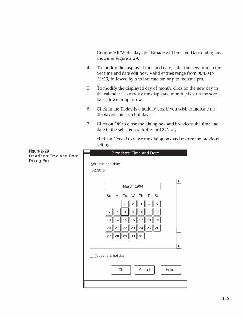
119
ComfortVIEW displays the Broadcast Time and Date dialog boxshown in Figure 2-29.
4. To modify the displayed time and date, enter the new time in theSet time and date edit box. Valid entries range from 00:00 to12:59, followed by a to indicate am or p to indicate pm.
5. To modify the displayed day of month, click on the new day inthe calendar. To modify the displayed month, click on the scrollbar’s down or up arrow.
6. Click in the Today is a holiday box if you wish to indicate thedisplayed date as a holiday.
7. Click on OK to close the dialog box and broadcast the time anddate to the selected controller or CCN or,
click on Cancel to close the dialog box and restore the previoussettings.
Broadcast Time and Date
Set time and date
02:30 p
OK Cancel Help...
Today is a holiday
March 1994
Su
1 2 3 4 5
6 7 8 9 10 11 12
19181716151413
20 21 22 23 24 25 26
3130292827
M Tu W Th F Sa
Figure 2-29Broadcast Time and DateDialog Box
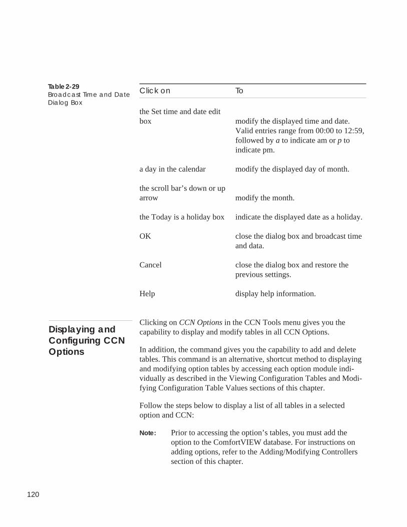
120
Click on To
the Set time and date editbox modify the displayed time and date.
Valid entries range from 00:00 to 12:59,followed by a to indicate am or p toindicate pm.
a day in the calendar modify the displayed day of month.
the scroll bar’s down or uparrow modify the month.
the Today is a holiday box indicate the displayed date as a holiday.
OK close the dialog box and broadcast timeand data.
Cancel close the dialog box and restore theprevious settings.
Help display help information.
Clicking on CCN Options in the CCN Tools menu gives you thecapability to display and modify tables in all CCN Options.
In addition, the command gives you the capability to add and deletetables. This command is an alternative, shortcut method to displayingand modifying option tables by accessing each option module indi-vidually as described in the Viewing Configuration Tables and Modi-fying Configuration Table Values sections of this chapter.
Follow the steps below to display a list of all tables in a selectedoption and CCN:
Note: Prior to accessing the option’s tables, you must add theoption to the ComfortVIEW database. For instructions onadding options, refer to the Adding/Modifying Controllerssection of this chapter.
Table 2-29Broadcast Time and DateDialog Box
Displaying andConfiguring CCNOptions
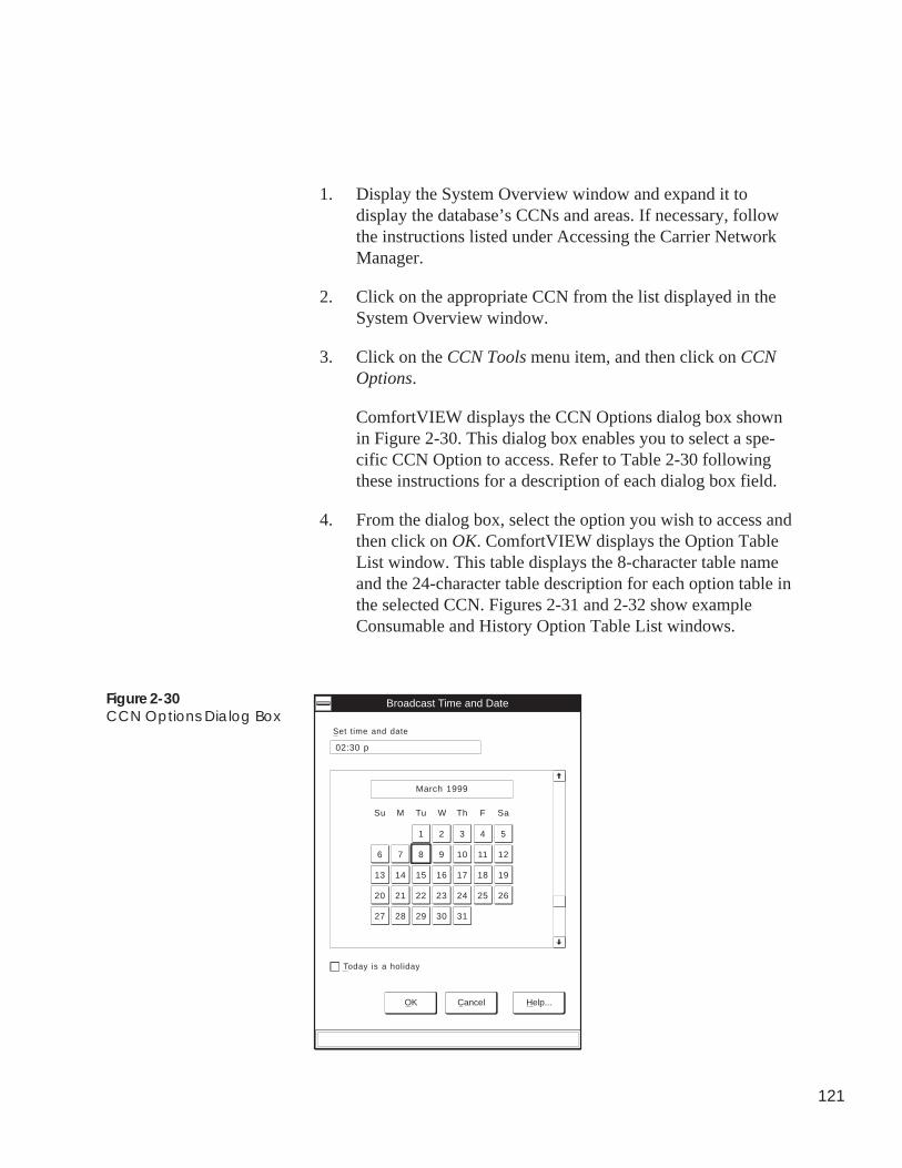
121
1. Display the System Overview window and expand it todisplay the database’s CCNs and areas. If necessary, followthe instructions listed under Accessing the Carrier NetworkManager.
2. Click on the appropriate CCN from the list displayed in theSystem Overview window.
3. Click on the CCN Tools menu item, and then click on CCNOptions.
ComfortVIEW displays the CCN Options dialog box shownin Figure 2-30. This dialog box enables you to select a spe-cific CCN Option to access. Refer to Table 2-30 followingthese instructions for a description of each dialog box field.
4. From the dialog box, select the option you wish to access andthen click on OK. ComfortVIEW displays the Option TableList window. This table displays the 8-character table nameand the 24-character table description for each option table inthe selected CCN. Figures 2-31 and 2-32 show exampleConsumable and History Option Table List windows.
Figure 2-30CCN Options Dialog Box
Broadcast Time and Date
Set time and date
02:30 p
OK Cancel Help...
Today is a holiday
March 1999
Su
1 2 3 4 5
6 7 8 9 10 11 12
19181716151413
20 21 22 23 24 25 26
3130292827
M Tu W Th F Sa
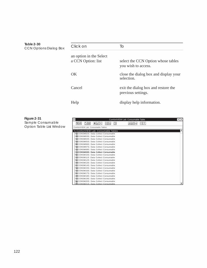
122
Click on To
an option in the Selecta CCN Option: list select the CCN Option whose tables
you wish to access.
OK close the dialog box and display yourselection.
Cancel exit the dialog box and restore theprevious settings.
Help display help information.
Table 2-30CCN Options Dialog Box
Figure 2-31Sample ConsumableOption Table List Window
ComfortVIEW Lab: Consumable Table
CONSM02S: Data Collect ConsumableComfortVIEW Lab: Consumable Tables
ComfortVIEW Lab: Consumable Tables
CONSM03S: Data Collect ConsumableCONSM04S: Data Collect ConsumableCONSM05S: Data Collect ConsumableCONSM06S: Data Collect ConsumableCONSM07S: Data Collect ConsumableCONSM08S: Data Collect ConsumableCONSM02S: Data Collect ConsumableCONSM09S: Data Collect ConsumableCONSM10S: Data Collect ConsumableCONSM11S: Data Collect ConsumableCONSM12S: Data Collect ConsumableCONSM13S: Data Collect ConsumableCONSM14S: Data Collect ConsumableCONSM15S: Data Collect ConsumableCONSM16S: Data Collect ConsumableCONSM17S: Data Collect ConsumableCONSM18S: Data Collect ConsumableCONSM19S: Data Collect ConsumableCONSM20S: Data Collect ConsumableCONSM21S: Data Collect Consumable
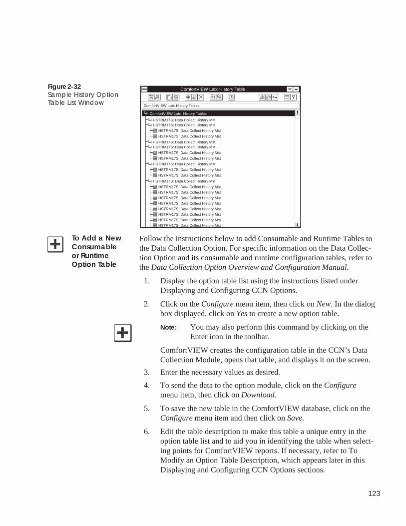
123
Figure 2-32Sample History OptionTable List Window
To Add a NewConsumableor RuntimeOption Table
Follow the instructions below to add Consumable and Runtime Tables tothe Data Collection Option. For specific information on the Data Collec-tion Option and its consumable and runtime configuration tables, refer tothe Data Collection Option Overview and Configuration Manual.
1. Display the option table list using the instructions listed underDisplaying and Configuring CCN Options.
2. Click on the Configure menu item, then click on New. In the dialogbox displayed, click on Yes to create a new option table.
Note: You may also perform this command by clicking on theEnter icon in the toolbar.
ComfortVIEW creates the configuration table in the CCN’s DataCollection Module, opens that table, and displays it on the screen.
3. Enter the necessary values as desired.
4. To send the data to the option module, click on the Configuremenu item, then click on Download.
5. To save the new table in the ComfortVIEW database, click on theConfigure menu item and then click on Save.
6. Edit the table description to make this table a unique entry in theoption table list and to aid you in identifying the table when select-ing points for ComfortVIEW reports. If necessary, refer to ToModify an Option Table Description, which appears later in thisDisplaying and Configuring CCN Options sections.
ComfortVIEW Lab: History Table
HSTRM17S: Data Collect History Mst
ComfortVIEW Lab: History Tables
ComfortVIEW Lab: History Tables
HSTRM17S: Data Collect History Mst
HSTRM17S: Data Collect History Mst
HSTRM17S: Data Collect History Mst
HSTRM17S: Data Collect History Mst
HSTRM17S: Data Collect History Mst
HSTRM17S: Data Collect History Mst
HSTRM17S: Data Collect History Mst
HSTRM17S: Data Collect History Mst
HSTRM17S: Data Collect History Mst
HSTRM17S: Data Collect History Mst
HSTRM17S: Data Collect History Mst
HSTRM17S: Data Collect History Mst
HSTRM17S: Data Collect History MstHSTRM17S: Data Collect History Mst
HSTRM17S: Data Collect History Mst
HSTRM17S: Data Collect History Mst
HSTRM17S: Data Collect History Mst
HSTRM17S: Data Collect History Mst
HSTRM17S: Data Collect History Mst
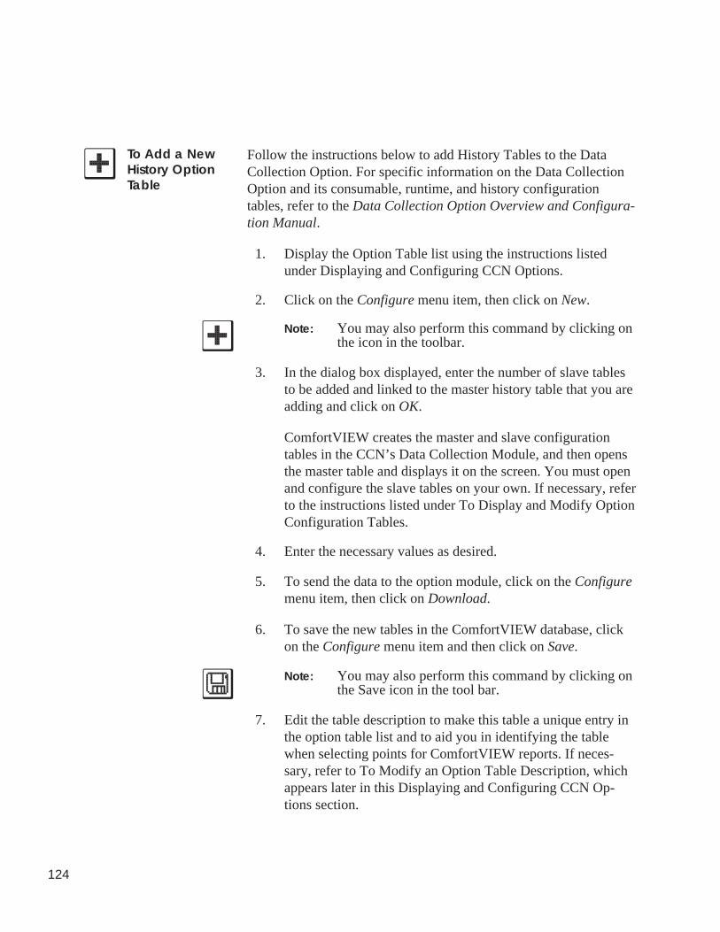
124
Follow the instructions below to add History Tables to the DataCollection Option. For specific information on the Data CollectionOption and its consumable, runtime, and history configurationtables, refer to the Data Collection Option Overview and Configura-tion Manual.
1. Display the Option Table list using the instructions listedunder Displaying and Configuring CCN Options.
2. Click on the Configure menu item, then click on New.
Note: You may also perform this command by clicking onthe icon in the toolbar.
3. In the dialog box displayed, enter the number of slave tablesto be added and linked to the master history table that you areadding and click on OK.
ComfortVIEW creates the master and slave configurationtables in the CCN’s Data Collection Module, and then opensthe master table and displays it on the screen. You must openand configure the slave tables on your own. If necessary, referto the instructions listed under To Display and Modify OptionConfiguration Tables.
4. Enter the necessary values as desired.
5. To send the data to the option module, click on the Configuremenu item, then click on Download.
6. To save the new tables in the ComfortVIEW database, clickon the Configure menu item and then click on Save.
Note: You may also perform this command by clicking onthe Save icon in the tool bar.
7. Edit the table description to make this table a unique entry inthe option table list and to aid you in identifying the tablewhen selecting points for ComfortVIEW reports. If neces-sary, refer to To Modify an Option Table Description, whichappears later in this Displaying and Configuring CCN Op-tions section.
To Add a NewHistory OptionTable
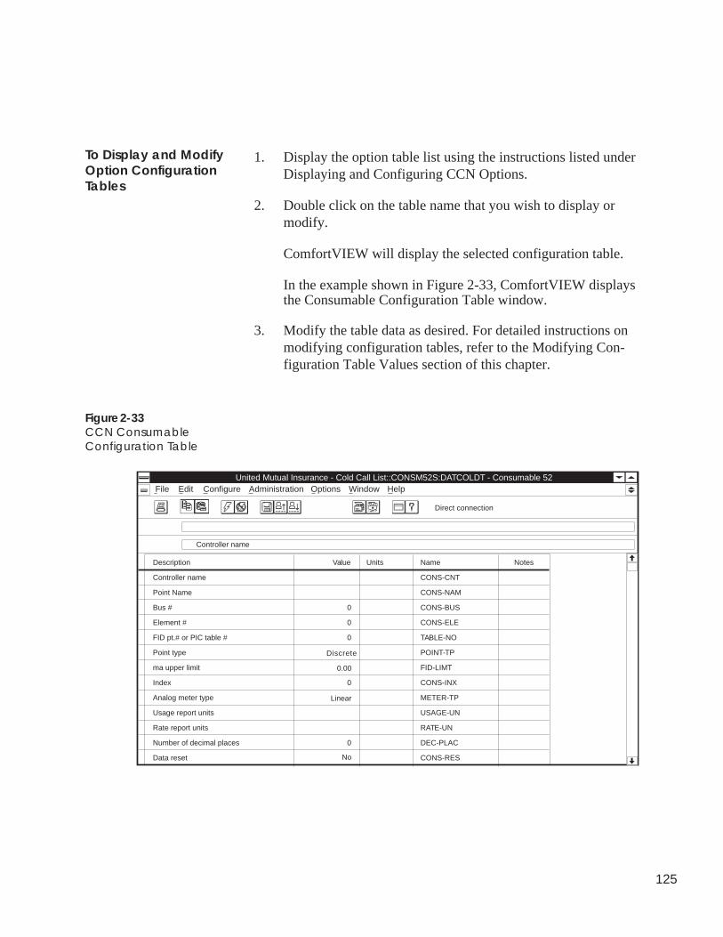
125
1. Display the option table list using the instructions listed underDisplaying and Configuring CCN Options.
2. Double click on the table name that you wish to display ormodify.
ComfortVIEW will display the selected configuration table.
In the example shown in Figure 2-33, ComfortVIEW displaysthe Consumable Configuration Table window.
3. Modify the table data as desired. For detailed instructions onmodifying configuration tables, refer to the Modifying Con-figuration Table Values section of this chapter.
To Display and ModifyOption ConfigurationTables
Figure 2-33CCN ConsumableConfiguration Table
AdministrationUnited Mutual Insurance - Cold Call List::CONSM52S:DATCOLDT - Consumable 52
File Edit Configure Options HelpWindow
Description Value Units Name Notes
Controller name
Direct connection
Controller name CONS-CNT
Point Name CONS-NAM
Bus # 0 CONS-BUS
Element # 0 CONS-ELE
FID pt.# or PIC table # 0 TABLE-NO
Point type Discrete POINT-TP
ma upper limit 0.00 FID-LIMT
Index 0 CONS-INX
Analog meter type Linear METER-TP
Usage report units USAGE-UN
Rate report units RATE-UN
Number of decimal places 0 DEC-PLAC
Data reset No CONS-RES
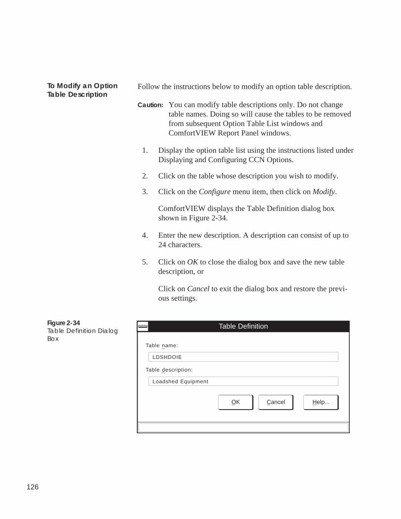
126
Follow the instructions below to modify an option table description.
Caution: You can modify table descriptions only. Do not changetable names. Doing so will cause the tables to be removedfrom subsequent Option Table List windows andComfortVIEW Report Panel windows.
1. Display the option table list using the instructions listed underDisplaying and Configuring CCN Options.
2. Click on the table whose description you wish to modify.
3. Click on the Configure menu item, then click on Modify.
ComfortVIEW displays the Table Definition dialog boxshown in Figure 2-34.
4. Enter the new description. A description can consist of up to24 characters.
5. Click on OK to close the dialog box and save the new tabledescription, or
Click on Cancel to exit the dialog box and restore the previ-ous settings.
To Modify an OptionTable Description
Figure 2-34Table Definition DialogBox
Table Definition
Table name:
LDSHDOIE
Table description:
Loadshed Equipment
OK Cancel Help...
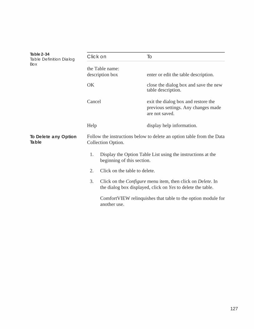
127
Table 2-34Table Definition DialogBox
Click on To
the Table name:description box enter or edit the table description.
OK close the dialog box and save the newtable description.
Cancel exit the dialog box and restore theprevious settings. Any changes madeare not saved.
Help display help information.
Follow the instructions below to delete an option table from the DataCollection Option.
1. Display the Option Table List using the instructions at thebeginning of this section.
2. Click on the table to delete.
3. Click on the Configure menu item, then click on Delete. Inthe dialog box displayed, click on Yes to delete the table.
ComfortVIEW relinquishes that table to the option module foranother use.
To Delete any OptionTable
128
ConfiguringUT203 FIDs
Follow the instructions below to configure a UT203 FID controller. Ifnecessary, refer to the UT203 FID Overview and ConfigurationManual for an explanation of the UT203 FID’s algorithms and con-figuration decisions.
Note: ComfortVIEW is compatible with UT203 FID Phase IV andsubsequent version controllers.
1. Display the Controller List window. If necessary, follow theinstructions listed under Displaying the Controller List.
2. Click on the UT203 FID controller that you wish to configure.
3. Activate the FID points:
a. Click on the Configure menu item and then click onController.
ComfortVIEW displays the FID Point Selection dialog boxshown in Figure 2-35.
b. In the Data Points Available list, select the points that youwish to activate.
Note: You can select multiple points using the Windows-standard mouse or keyboard techniques.
c. Click on Add. The points will appear in the Data Points inSystem list.
Note: Use of the Controller command (by you or anyother operator) while displaying any FID table willresult in the display of a Controller in use or Con-troller currently locked message.
4. Assign the point types:
a. In the Data Points in System list, click on the point that youwish to configure and then click on Modify.
ComfortVIEW displays the FID Point Assignment dialogbox shown in Figure 2-36. The current point name anddescription display in the Name and Description text box.
b. If desired, click on the point name and description textboxes to modify the point name and description.
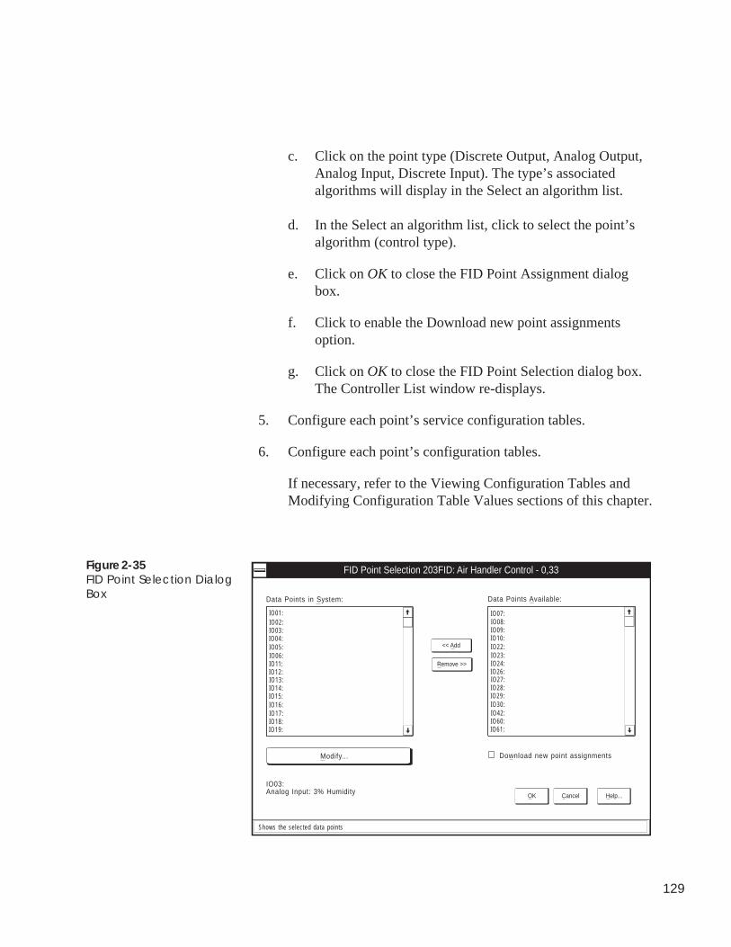
129
c. Click on the point type (Discrete Output, Analog Output,Analog Input, Discrete Input). The type’s associatedalgorithms will display in the Select an algorithm list.
d. In the Select an algorithm list, click to select the point’salgorithm (control type).
e. Click on OK to close the FID Point Assignment dialogbox.
f. Click to enable the Download new point assignmentsoption.
g. Click on OK to close the FID Point Selection dialog box.The Controller List window re-displays.
5. Configure each point’s service configuration tables.
6. Configure each point’s configuration tables.
If necessary, refer to the Viewing Configuration Tables andModifying Configuration Table Values sections of this chapter.
Figure 2-35FID Point Selection DialogBox
FID Point Selection 203FID: Air Handler Control - 0,33
OK Cancel Help...
Download new point assignments
IO01:
Data Points in System:
<< Add
Remove >>
IO02:IO03:IO04:IO05:IO06:IO11:IO12:IO13:IO14:IO15:IO16:IO17:IO18:IO19:
Modify...
IO03:Analog Input: 3% Humidity
IO07:
Data Points Available:
IO08:IO09:IO10:IO22:IO23:IO24:IO26:IO27:IO28:IO29:IO30:IO42:IO60:IO61:
Shows the selected data points
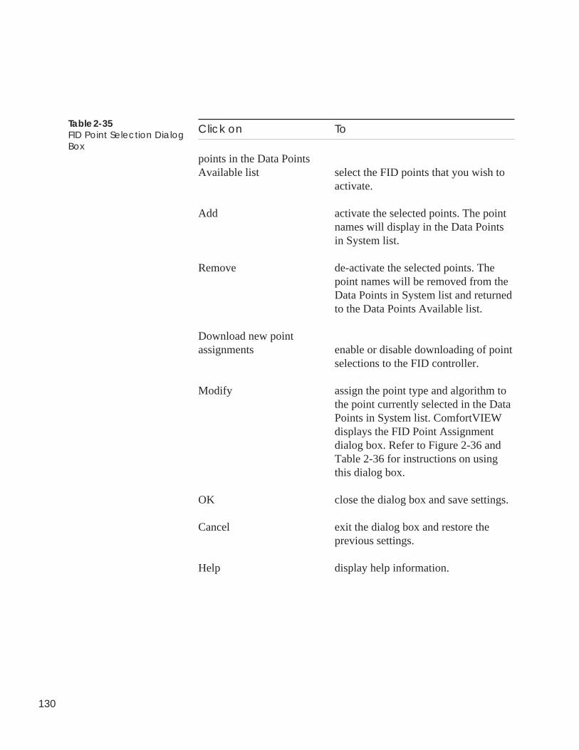
130
Click on To
points in the Data PointsAvailable list select the FID points that you wish to
activate.
Add activate the selected points. The pointnames will display in the Data Pointsin System list.
Remove de-activate the selected points. Thepoint names will be removed from theData Points in System list and returnedto the Data Points Available list.
Download new pointassignments enable or disable downloading of point
selections to the FID controller.
Modify assign the point type and algorithm tothe point currently selected in the DataPoints in System list. ComfortVIEWdisplays the FID Point Assignmentdialog box. Refer to Figure 2-36 andTable 2-36 for instructions on usingthis dialog box.
OK close the dialog box and save settings.
Cancel exit the dialog box and restore theprevious settings.
Help display help information.
Table 2-35FID Point Selection DialogBox
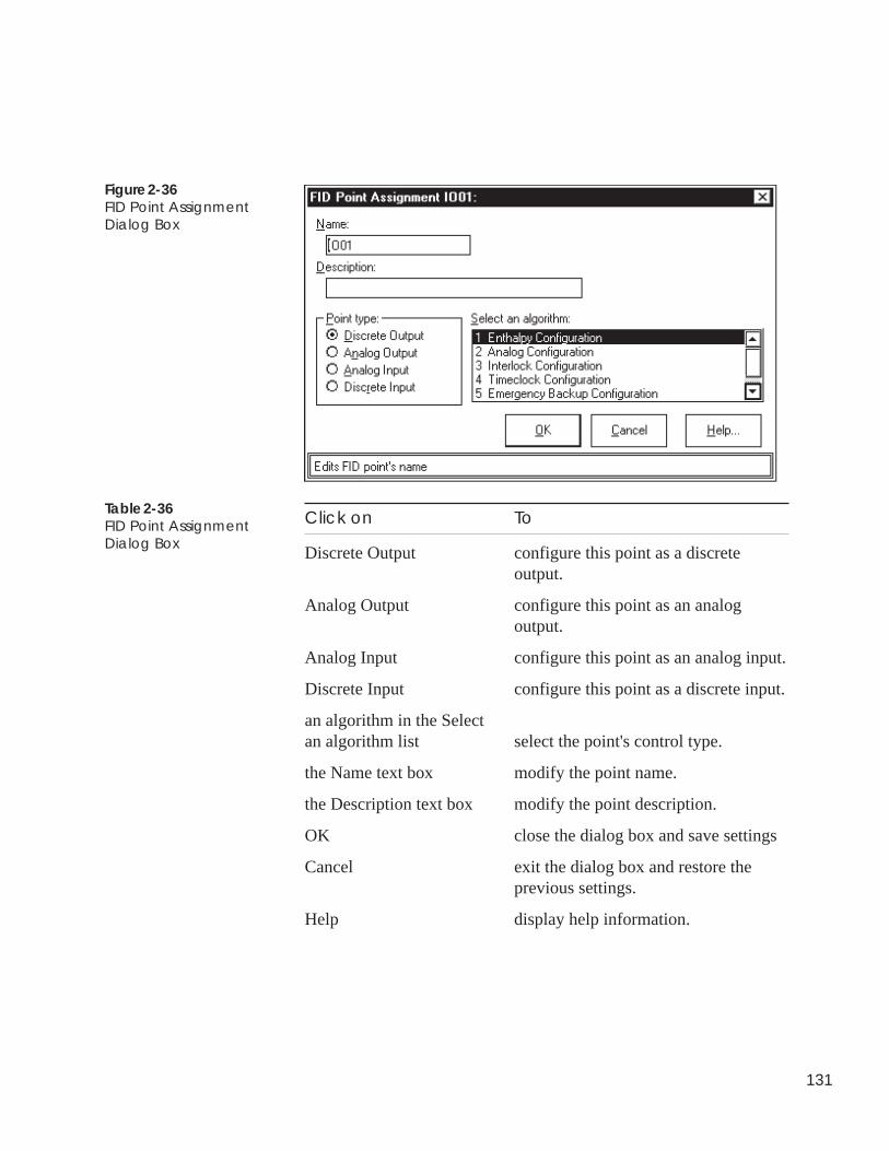
131
Figure 2-36FID Point AssignmentDialog Box
Click on To
Discrete Output configure this point as a discreteoutput.
Analog Output configure this point as an analogoutput.
Analog Input configure this point as an analog input.
Discrete Input configure this point as a discrete input.
an algorithm in the Selectan algorithm list select the point's control type.
the Name text box modify the point name.
the Description text box modify the point description.
OK close the dialog box and save settings
Cancel exit the dialog box and restore theprevious settings.
Help display help information.
Table 2-36FID Point AssignmentDialog Box
132
ConfiguringComfortControllers
ComfortVIEW contains a programming interface for the ComfortController. Comfort Controller configuration consists of two phases:
• Creating database objects (hardware and software points, algo-rithms, setpoints, alarms, functions, and system tables) in theblank Comfort Controller database.
• Configuring the objects.
If necessary, refer to the Comfort Controller Overview and Configu-ration Manual (808-891) for a list of the Comfort Controller'sdatabase objects and a description of the accompanying configura-tion decisions.
The Comfort Controller receives commands from ComfortVIEW asyou work to create and configure the database objects.
Note: The ComfortVIEW Comfort Controller configurationfeature only applies to Comfort Controllers 1600 and 6400Version 1.3 and greater.
The ComfortVIEW programming interface is very different fromCarrier's Network Service Tool Quickstart and On-line ComfortController configuration tools. ComfortVIEW requires fewer in-terim steps for the creation of an object and offers an easier methodof object configuration. Also, any object additions, deletions, ormodifications made to the Comfort Controller are also simulta-neously made to the ComfortVIEW controller database image.
As you use ComfortVIEW to create, delete, or modify objects andenable the download to Comfort Controller option, programmingcommands are sent (downloaded) from ComfortVIEW to the Com-fort Controller. As this happens, ComfortVIEW creates an image ofthe controller in its own database. ComfortVIEW records andmaintains all controller object changes made in this way. As a result,you never have to upload your Comfort Controller to theComfortVIEW database, and any changes that are made to thenumber and types of controller objects are automatically synchro-nized with the contents of your ComfortVIEW database. You muststill, however, save and manually download Comfort Controllertable configuration changes.
As long as you enable the download to Comfort Controller option,and also download table configuration changes to the controller, theComfortVIEW database remains synchronized with the actual
Important Featuresand Considerations
133
controller object database and configuration. If, however, you optnot to download an object or configuration table change fromComfortVIEW to the Comfort Controller, you will have a mismatchbetween the controller's and the ComfortVIEW database.
If you suspect a mismatch between the Comfort Controller and theComfortVIEW database, perform a controller verification by click-ing on the Configure menu item and then clicking on Verify . Anydifferences will be detected and recorded for your viewing. If thereare differences that you wish to rectify, either upload the existingComfort Controller to ComfortVIEW or download the existingComfortVIEW database to the Comfort Controller.
If you have programmed and configured a new Comfort Controllerusing the Network Service Tool's Quickstart and On-Line configura-tion tools or some other user interface, simply upload the controllerto ComfortVIEW. Once it is uploaded, you can use ComfortVIEWto make all future configuration changes.
If you use the Network Service Tool's Quickstart and On-Lineconfiguration tools, or some other user interface to locally makeobject or configuration modifications to a Comfort Controller thatalready exists in the ComfortVIEW database, simply upload thecontroller to ComfortVIEW. There is no need to delete the ComfortController and re-add it to the ComfortVIEW database, as there wasin previous ComfortVIEW versions. Uploading makes all thenecessary changes to the ComfortVIEW database to keepComfortVIEW and the Comfort Controller's database synchronized.
Note: Uploading a Comfort Controller to an existing ComfortController in the ComfortVIEW database will overwritethe ComfortVIEW database as necessary in order to createan exact image of the actual Comfort Controller database.It is recommended that you use the Verify command priorto performing the upload to note the differences in the twodatabases.
If you use ComfortVIEW to assign custom engineering units to aComfort Controller point, the custom units will not display if youuse another user interface to display the point.
Recovering fromDatabase Mismatch
Use of Other UserInterfaces to ProgramComfort Controllers
134
This procedure provides instructions for creating, modifying, andconfiguring objects in the ComfortVIEW database, and optionallycreating and configuring them in the Comfort Controller. Prior tobeginning these instructions, you must add the Comfort Controllerto your ComfortVIEW database. For instructions on adding control-lers, follow the instructions in the Adding/Modify Controllerssection of this Carrier Network Manager chapter.
If desired, you can perform this procedure without being physicallyconnected to an actual Comfort Controller. Use the Comfort ControllerVersion 1.3 templates that are provided with your ComfortVIEWsoftware for importing.` These templates are named CC640013.CWXand CC160013.CWX and are located in the directory path\CCNPATH\TEMPLATE. This directory path will be located in the\CVIEW , \CWORKS or other directory in which you installedComfortVIEW. Once your configuration is complete, you can exportthe file to disk in order to import it at another ComfortVIEW site, oryou may connect a Comfort Controller to your ComfortVIEW PC anddownload the configuration to the Comfort Controller. For ComfortController downloading instructions, refer to DownloadingComfortVIEW data to a Comfort Controller, which appears later in thisConfiguring Comfort Controllers section.
1. Display the Controller List window. If necessary, follow theinstructions listed in the Displaying the Controller List sec-tion of this chapter.
2. Click on the Comfort Controller that you wish to create.
3. Click on the Configure menu item and then click on Controller.
ComfortVIEW displays the Configure Comfort Controllertabbed dialog box shown and described in Figure 2-36a andTable 2-36a. This dialog box contains a series of tabs, each ofwhich provides access to the Comfort Controller's differentdatabase objects. When you initially display this dialog box,the Hardware tab will be selected.
Note: The tabs in this dialog box are arranged in therecommended order of configuration.
4. Create and configure the hardware and software points thatyour application requires by following the Creating and Modi-fying Hardware and Software Points procedure, which appearslater in these Configuring Comfort Controllers instructions.
Procedure Overview
135
5. Create and configure the setpoint schedules that your applica-tion requires by following the Creating Other DatabaseObjects: Setpoints, System Tables, Alarms, Functions, Algo-rithms procedure, which appears later in these ConfiguringComfort Controllers instructions.
6. Create and configure the system tables (Consumable,Runtime, Holiday, Network Time Schedule, Loadshed,Language Conversion) that your application requires byfollowing the Creating Other Database Objects: Setpoints,System Tables, Alarms, Functions, Algorithms procedure,which appears later in these Configuring Comfort Controllersinstructions.
7. Create and configure the alarms (Limit, Setpoint Limit,Discrete State, First Out, Runtime, Number of Starts) thatyour application requires by following the Creating OtherDatabase Objects: Setpoints, System Tables, Alarms, Func-tions, Algorithms procedure, which appears later in theseConfiguring Comfort Controllers instructions.
8. Create and configure the functions (Analog Trace Point,Discrete Trace Point, Internal Consumable, Adaptive OptimalStart/Stop, Network Broadcast, Linkage/AOSS Schedule,Night Time Free Cooling, Occupancy) that your applicationrequires by following the Creating Other Database Objects:Setpoints, System Tables, Alarms, Functions, Algorithmsprocedure, which appears later in these Configuring ComfortControllers instructions.
9. Create and configure the algorithms that your applicationrequires by following the Creating Other Database Objects:Setpoints, System Tables, Alarms, Functions, Algorithmsprocedure, which appears later in these Configuring ComfortControllers instructions.
10. After you create and configure all database objects, click onthe Configure Comfort Controller dialog box's Close button.ComfortVIEW closes the dialog box and proceeds to buildthe status display tables. A message dialog box displaysduring this process.
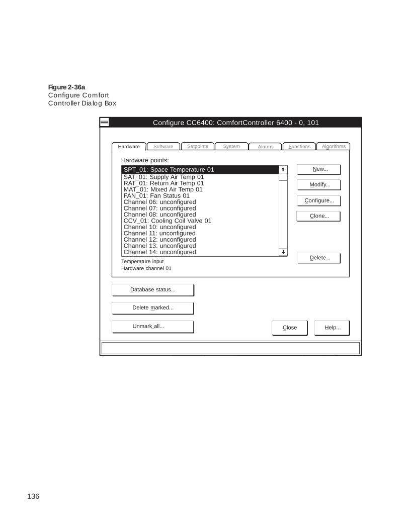
136
Figure 2-36aConfigure ComfortController Dialog Box
Modify...
Hardware points:
Configure CC6400: ComfortController 6400 - 0, 101
SPT_01: Space Temperature 01 New...
Clone...
Configure...
Delete...
Alarms Functions AlgorithmsSetpoints SystemHardware Software
Temperature inputHardware channel 01
Database status...
SAT_01: Supply Air Temp 01RAT_01: Return Air Temp 01MAT_01: Mixed Air Temp 01FAN_01: Fan Status 01Channel 06: unconfiguredChannel 07: unconfiguredChannel 08: unconfiguredCCV_01: Cooling Coil Valve 01Channel 10: unconfiguredChannel 11: unconfiguredChannel 12: unconfiguredChannel 13: unconfiguredChannel 14: unconfigured
Delete marked...
Unmark all... Close Help...
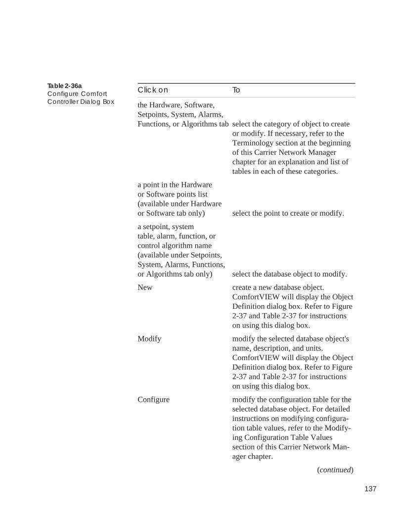
137
Click on To
the Hardware, Software,Setpoints, System, Alarms,Functions, or Algorithms tab select the category of object to create
or modify. If necessary, refer to theTerminology section at the beginningof this Carrier Network Managerchapter for an explanation and list oftables in each of these categories.
a point in the Hardwareor Software points list(available under Hardwareor Software tab only) select the point to create or modify.
a setpoint, systemtable, alarm, function, orcontrol algorithm name(available under Setpoints,System, Alarms, Functions,or Algorithms tab only) select the database object to modify.
New create a new database object.ComfortVIEW will display the ObjectDefinition dialog box. Refer to Figure2-37 and Table 2-37 for instructionson using this dialog box.
Modify modify the selected database object'sname, description, and units.ComfortVIEW will display the ObjectDefinition dialog box. Refer to Figure2-37 and Table 2-37 for instructionson using this dialog box.
Configure modify the configuration table for theselected database object. For detailedinstructions on modifying configura-tion table values, refer to the Modify-ing Configuration Table Valuessection of this Carrier Network Man-ager chapter.
(continued)
Table 2-36aConfigure ComfortController Dialog Box
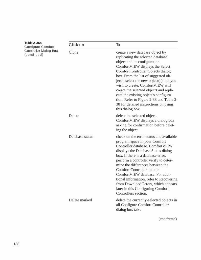
138
Click on To
Clone create a new database object byreplicating the selected databaseobject and its configuration.ComfortVIEW displays the SelectComfort Controller Objects dialogbox. From the list of suggested ob-jects, select the new object(s) that youwish to create. ComfortVIEW willcreate the selected objects and repli-cate the existing object's configura-tion. Refer to Figure 2-38 and Table 2-38 for detailed instructions on usingthis dialog box.
Delete delete the selected object.ComfortVIEW displays a dialog boxasking for confirmation before delet-ing the object.
Database status check on the error status and availableprogram space in your ComfortController database. ComfortVIEWdisplays the Database Status dialogbox. If there is a database error,perform a controller verify to deter-mine the differences between theComfort Controller and theComfortVIEW database. For addi-tional information, refer to Recoveringfrom Download Errors, which appearslater in this Configuring ComfortControllers section.
Delete marked delete the currently-selected objects inall Configure Comfort Controllerdialog box tabs.
(continued)
Table 2-36aConfigure ComfortController Dialog Box(continued)
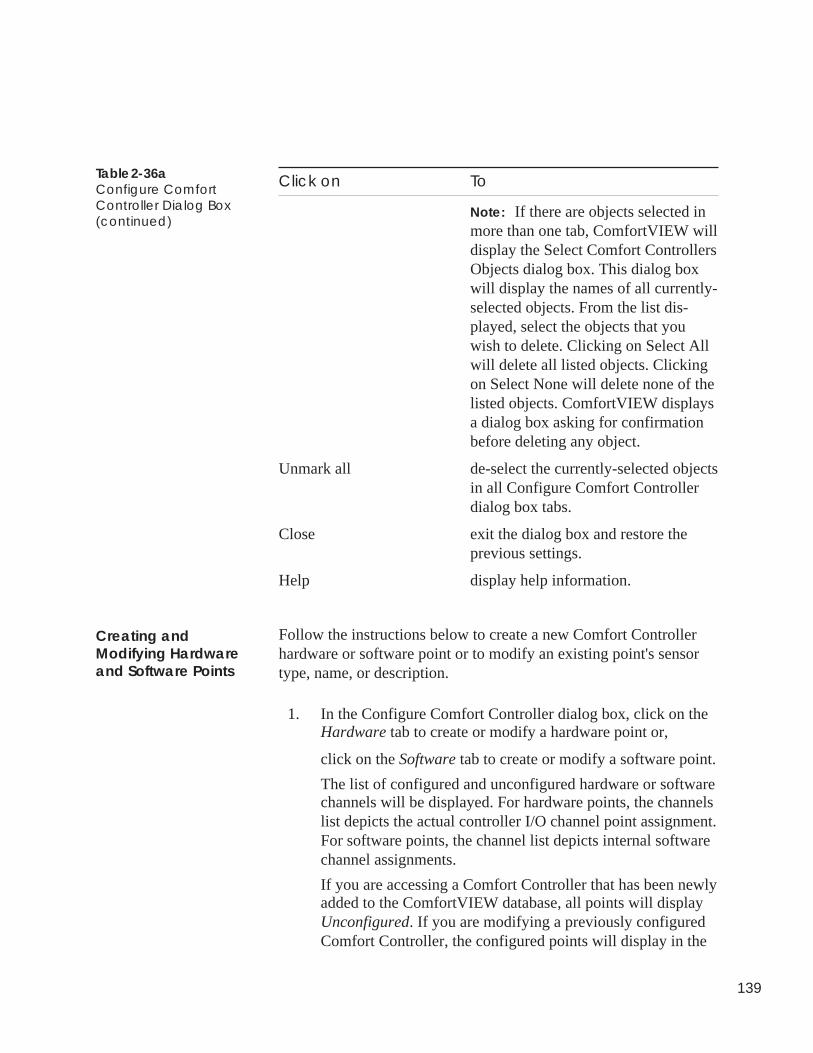
139
Click on To
Note: If there are objects selected inmore than one tab, ComfortVIEW willdisplay the Select Comfort ControllersObjects dialog box. This dialog boxwill display the names of all currently-selected objects. From the list dis-played, select the objects that youwish to delete. Clicking on Select Allwill delete all listed objects. Clickingon Select None will delete none of thelisted objects. ComfortVIEW displaysa dialog box asking for confirmationbefore deleting any object.
Unmark all de-select the currently-selected objectsin all Configure Comfort Controllerdialog box tabs.
Close exit the dialog box and restore theprevious settings.
Help display help information.
Follow the instructions below to create a new Comfort Controllerhardware or software point or to modify an existing point's sensortype, name, or description.
1. In the Configure Comfort Controller dialog box, click on theHardware tab to create or modify a hardware point or,
click on the Software tab to create or modify a software point.
The list of configured and unconfigured hardware or softwarechannels will be displayed. For hardware points, the channelslist depicts the actual controller I/O channel point assignment.For software points, the channel list depicts internal softwarechannel assignments.
If you are accessing a Comfort Controller that has been newlyadded to the ComfortVIEW database, all points will displayUnconfigured. If you are modifying a previously configuredComfort Controller, the configured points will display in the
Table 2-36aConfigure ComfortController Dialog Box(continued)
Creating andModifying Hardwareand Software Points
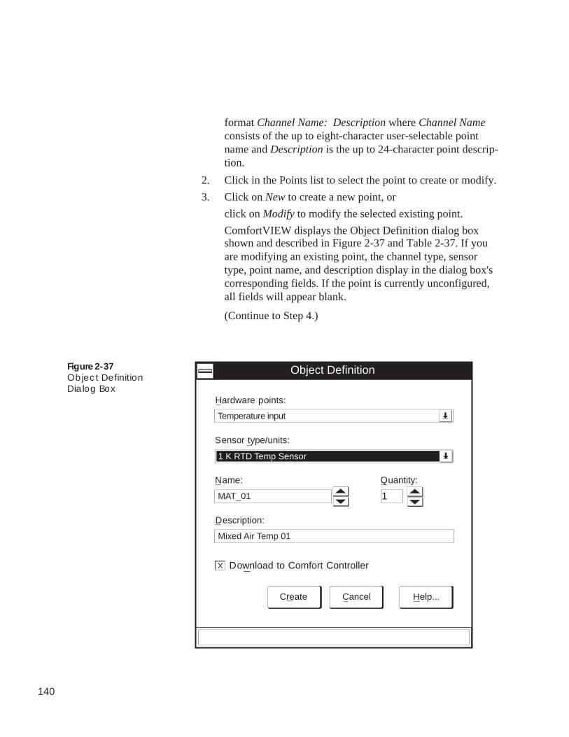
140
format Channel Name: Description where Channel Nameconsists of the up to eight-character user-selectable pointname and Description is the up to 24-character point descrip-tion.
2. Click in the Points list to select the point to create or modify.
3. Click on New to create a new point, or
click on Modify to modify the selected existing point.
ComfortVIEW displays the Object Definition dialog boxshown and described in Figure 2-37 and Table 2-37. If youare modifying an existing point, the channel type, sensortype, point name, and description display in the dialog box'scorresponding fields. If the point is currently unconfigured,all fields will appear blank.
(Continue to Step 4.)
Figure 2-37Object DefinitionDialog Box
Hardware points:
Create Cancel Help...
Description:
Name:
Sensor type/units:
Temperature input
1 K RTD Temp Sensor
MAT_01
Mixed Air Temp 01
1
Quantity:
Download to Comfort Controller
X
Object Definition
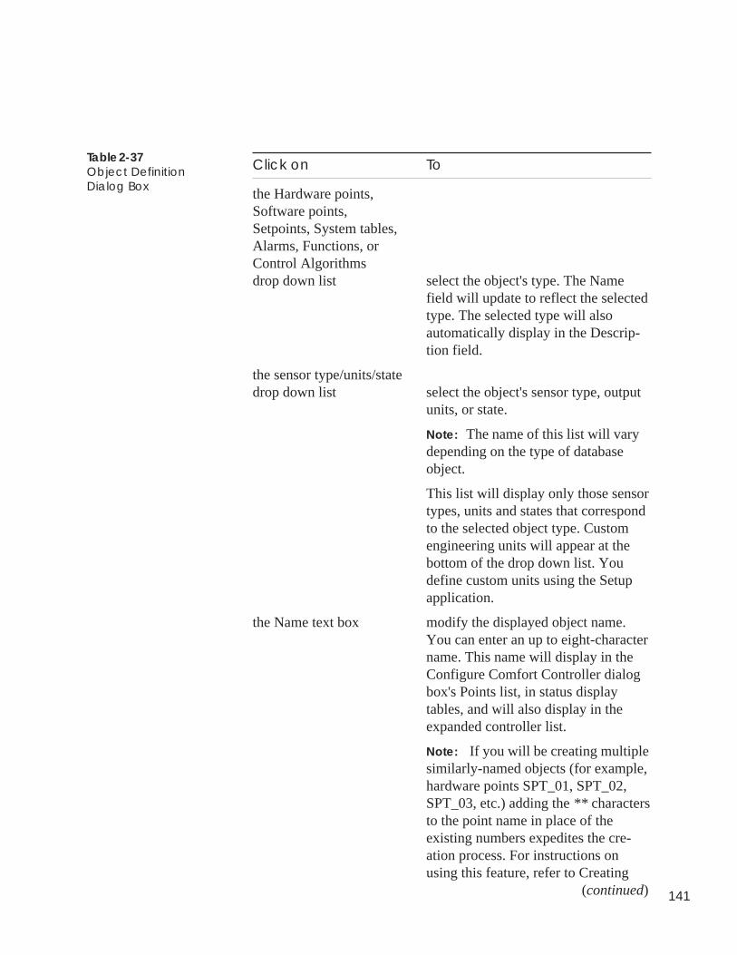
141
Click on To
the Hardware points,Software points,Setpoints, System tables,Alarms, Functions, orControl Algorithmsdrop down list select the object's type. The Name
field will update to reflect the selectedtype. The selected type will alsoautomatically display in the Descrip-tion field.
the sensor type/units/statedrop down list select the object's sensor type, output
units, or state.
Note: The name of this list will varydepending on the type of databaseobject.
This list will display only those sensortypes, units and states that correspondto the selected object type. Customengineering units will appear at thebottom of the drop down list. Youdefine custom units using the Setupapplication.
the Name text box modify the displayed object name.You can enter an up to eight-charactername. This name will display in theConfigure Comfort Controller dialogbox's Points list, in status displaytables, and will also display in theexpanded controller list.
Note: If you will be creating multiplesimilarly-named objects (for example,hardware points SPT_01, SPT_02,SPT_03, etc.) adding the ** charactersto the point name in place of theexisting numbers expedites the cre-ation process. For instructions onusing this feature, refer to Creating
(continued)
Table 2-37Object DefinitionDialog Box
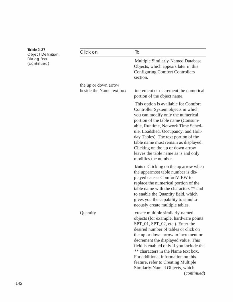
142
Click on To
Multiple Similarly-Named DatabaseObjects, which appears later in thisConfiguring Comfort Controllerssection.
the up or down arrowbeside the Name text box increment or decrement the numerical
portion of the object name.
This option is available for ComfortController System objects in whichyou can modify only the numericalportion of the table name (Consum-able, Runtime, Network Time Sched-ule, Loadshed, Occupancy, and Holi-day Tables). The text portion of thetable name must remain as displayed.Clicking on the up or down arrowleaves the table name as is and onlymodifies the number.
Note: Clicking on the up arrow whenthe uppermost table number is dis-played causes ComfortVIEW toreplace the numerical portion of thetable name with the characters ** andto enable the Quantity field, whichgives you the capability to simulta-neously create multiple tables.
Quantity create multiple similarly-namedobjects (for example, hardware pointsSPT_01, SPT_02, etc.). Enter thedesired number of tables or click onthe up or down arrow to increment ordecrement the displayed value. Thisfield is enabled only if you include the** characters in the Name text box.For additional information on thisfeature, refer to Creating MultipleSimilarly-Named Objects, which
(continued)
Table 2-37Object DefinitionDialog Box(continued)
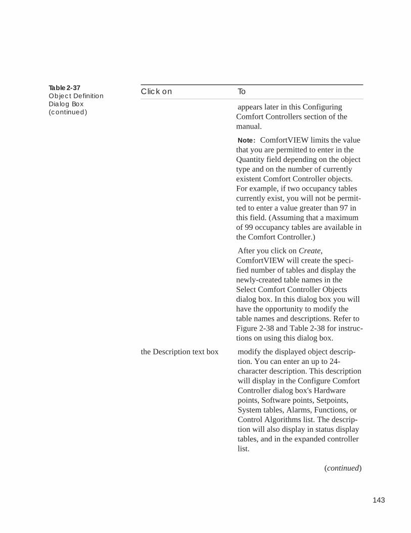
143
Click on To
appears later in this ConfiguringComfort Controllers section of themanual.
Note: ComfortVIEW limits the valuethat you are permitted to enter in theQuantity field depending on the objecttype and on the number of currentlyexistent Comfort Controller objects.For example, if two occupancy tablescurrently exist, you will not be permit-ted to enter a value greater than 97 inthis field. (Assuming that a maximumof 99 occupancy tables are available inthe Comfort Controller.)
After you click on Create,ComfortVIEW will create the speci-fied number of tables and display thenewly-created table names in theSelect Comfort Controller Objectsdialog box. In this dialog box you willhave the opportunity to modify thetable names and descriptions. Refer toFigure 2-38 and Table 2-38 for instruc-tions on using this dialog box.
the Description text box modify the displayed object descrip-tion. You can enter an up to 24-character description. This descriptionwill display in the Configure ComfortController dialog box's Hardwarepoints, Software points, Setpoints,System tables, Alarms, Functions, orControl Algorithms list. The descrip-tion will also display in status displaytables, and in the expanded controllerlist.
(continued)
Table 2-37Object DefinitionDialog Box(continued)
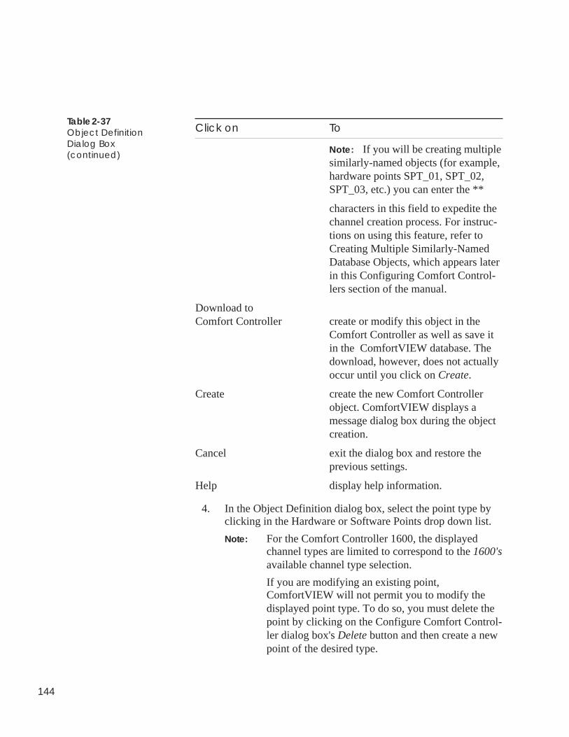
144
Click on To
Note: If you will be creating multiplesimilarly-named objects (for example,hardware points SPT_01, SPT_02,SPT_03, etc.) you can enter the **
characters in this field to expedite thechannel creation process. For instruc-tions on using this feature, refer toCreating Multiple Similarly-NamedDatabase Objects, which appears laterin this Configuring Comfort Control-lers section of the manual.
Download toComfort Controller create or modify this object in the
Comfort Controller as well as save itin the ComfortVIEW database. Thedownload, however, does not actuallyoccur until you click on Create.
Create create the new Comfort Controllerobject. ComfortVIEW displays amessage dialog box during the objectcreation.
Cancel exit the dialog box and restore theprevious settings.
Help display help information.
4. In the Object Definition dialog box, select the point type byclicking in the Hardware or Software Points drop down list.
Note: For the Comfort Controller 1600, the displayedchannel types are limited to correspond to the 1600'savailable channel type selection.
If you are modifying an existing point,ComfortVIEW will not permit you to modify thedisplayed point type. To do so, you must delete thepoint by clicking on the Configure Comfort Control-ler dialog box's Delete button and then create a newpoint of the desired type.
Table 2-37Object DefinitionDialog Box(continued)
145
The Name field will update to reflect the selected point type.For example, if you are creating a point on Channel 8 andselect the point type Milliamp Output, the point nameMAOUT08 will automatically display in the Name field.
The selected point type will also automatically display in theDescription field.
5. If desired, you can modify the point name and description byclicking in the appropriate fields.
The point name and description will display in the Points list,in status display tables, and in the expanded controller list.
Note: If you will be creating multiple similarly-namedchannels (for example, SPT_01, SPT_02, SPT_03,etc.), you can enter the ** characters in the numericfields of these names to expedite the channel cre-ation process. For instructions on using this timesaving feature, refer to Creating Multiple Similarly-Named Database Objects, which appears later in thisConfiguring Comfort Controllers section of themanual.
6. Select the sensor type or output units by clicking in theSensor Type/Units drop down list.
Note: The sensor type list will display only those sensortypes that correspond to the selected point type. Toselect custom engineering units, pull down to thebottom of the list. Custom units are defined usingComfortVIEW Setup application.
7. If you wish to create or modify this channel in the ComfortController as well as in the ComfortVIEW database, click onDownload to Comfort Controller.
Note: If you do not select this option, ComfortVIEW willcreate the channel only in its database. The channelwill not be created in the Comfort Controller. Ifdesired, you can work off-line and create the con-figuration in the ComfortVIEW database only.Then, when you are ready to send the information tothe Comfort Controller, you can simply perform acontroller download of the entire configurationusing the Configure menu's Download command.To Download an entire Comfort Controller instruc-tions, refer to the instructions which appear later inthis Configuring Comfort Controllers section.
146
When working off-line, however, be sure to keeptrack of the amount of Comfort Controller memoryyou will be using. Refer to the EEPROM MemoryUsage Summary Sheet in the Comfort ControllerOverview and Configuration Manual for approxi-mate database object memory usages.
8. Click on Create to create the new or modified point informa-tion and display the configuration table, or
Click on Cancel to exit the dialog box and restore the previ-ous settings.
ComfortVIEW displays a message dialog box during thecreation process. At the conclusion, the point's configurationtable is displayed.
9. You can opt to configure the point here, or you can exit theconfiguration table and return to configure the point at a latertime using the Configure Comfort Controller dialog box'sConfigure button. For configuration instructions, refer toConfiguring Database Objects, which appears later in thisConfiguring Comfort Controllers section.
Follow the instructions below to create or modify the followingComfort Controller database objects:
• Setpoint schedules• System tables (Consumable, Runtime, Holiday, Network Time
Schedule, Loadshed, Language Conversion)• Alarms (Limit, Setpoint Limit, Discrete State, First Out,
Runtime, Number of Starts)• Functions (Analog Trace Point, Discrete Trace Point, Internal
Consumable, Adaptive Optimal Start/Stop, Network Broadcast,Linkage/AOSS Schedule, Night Time Free Cooling, Occupancy)
• Algorithms.
Note: ComfortVIEW gives you the capability to create up to 99setpoint schedules. If you are using Carrier's NetworkService Tool or Building Supervisor interface, however,you will only be able to access the first 16 of these sched-ules. The same situation holds true for alarms, functions,
Creating andModifying OtherDatabase Objects:Setpoints, SystemTables, Alarms,Functions, Algorithms
147
and algorithms. ComfortVIEW allows you to create anunlimited number of these objects. If you are using theNetwork Service Tool or Building Supervisor, however,you will only have access to the first 96 objects of thesetypes in the Comfort Controller 6400 and the first 24 inthe Comfort Controller 1600. You will still, however, begoverned by the amount of available Comfort Controllermemory.
1. In the Configure Comfort Controller dialog box, click on thetab that corresponds to the type of database object you wishto create or modify:
SetpointSystemAlarmsFunctionsAlgorithms
A list of existing database objects will be displayed in theformat Object Name: Description where Object Nameconsists of the up to eight-character user-selectable name andDescription is the up to 24-character description. If you areaccessing a Comfort Controller that has been newly added tothe ComfortVIEW database, this list will be empty.
2. Click on New to create a new object, or
select an existing object and then click on Modify to modifythe selected object's type/units/state, name, or description.
ComfortVIEW displays the Object Definition dialog boxshown and described in Figure 2-37 and Table 2-37. If youare modifying an existing object, the object's identificationinformation will display in the corresponding fields. If youare adding a new object, all fields will appear blank.
3. In the Object Definition dialog box, select the object type byclicking in the top most drop down list. Depending on thetype of database object you are working with, this list will belabelled Setpoints, System tables, Alarms, Functions, orControl Algorithms drop down list.
Note: If you are modifying an existing object,ComfortVIEW will not permit you to modify thedisplayed object type. To do so, you must delete theobject by clicking on the Configure Comfort Con-
148
troller dialog box's Delete button and then create anew one of the desired type.
The Name field will update to reflect the selected object type.For example, if you are creating a system table and select thesystem table type Holiday, the name HOLDY01 will auto-matically display in the Name field.
Note: When naming new tables, ComfortVIEW keepstrack of existing table instances. For example, IfHOLDY01 and 02 already exist, ComfortVIEWwould name a new table HOLDY03.
The selected object type will also automatically display in theDescription field.
4. If desired, you can modify the object name and description byclicking in the appropriate fields.
Note: You cannot modify the full name of system objects.You can only modify the numerical portion of thename. To do this, click on the up or down arrow thatis located beside the Name text box.
The name and description will display in the expanded con-troller list.
Note: If you will be creating multiple similarly-namedobjects (for example, multiple Limit Alarm objects,LMALM_01, LMALM_02, LMALM_03, etc.), youcan enter the ** characters in the numeric fields ofthese names to expedite the object creation process.For instructions on using this time saving feature,refer to Creating Multiple Similarly-Named Data-base Objects, which appears later in this Configur-ing Comfort Controllers section of the manual.
5. Select the sensor type, output units, or state by clicking in theSensor Type/Units/State drop down list.
6. If you wish to create or modify this object in the ComfortController as well as in the ComfortVIEW database, click onDownload to Comfort Controller.
Note: If you do not select this option, ComfortVIEW willcreate the object only in its database. The objectwill not be created in the Comfort Controller. Ifdesired, you can work off-line in this way and createthe configuration in the ComfortVIEW databaseonly. Then, when you are ready to send the informa-
149
tion to the Comfort Controller, you can simplyperform a controller download of the entire configu-ration using the Configure menu's Download com-mand.
When working off-line, however, be sure to keeptrack of the amount of Comfort Controller memoryyou will be using. Refer to the EEPROM MemoryUsage Summary Sheet in the Comfort ControllerOverview and Configuration Manual for approxi-mate database object memory usages.
7. Click on Create to create the the new or modified object anddisplay the configuration table, or
Click on Cancel to exit the dialog box and restore the previ-ous settings.
ComfortVIEW displays a message dialog box during thecreation process. At the conclusion, the point's configurationtable is displayed.
8. You can opt to configure the object here, or can exit theconfiguration table and return to configure the object at a latertime using the Configure Comfort Controller dialog box'sConfigure button. For configuration instructions, refer toConfiguring Database Objects, which appears later in thisConfiguring Comfort Controllers section.
ComfortVIEW includes a feature that is designed to expedite thecreation of multiple similarly-named and/or similarly-described objects(For example, SPT_01 (Space Temperature 01), SPT_02 (Space Tem-perature 02), SPT_03 (Space Temperature 03)). You initiate this featurewhile creating or modifying an existing database object.
To create multiple objects:
1. Following the instructions listed under Creating and Modify-ing Hardware and Software Channels or Creating and Modi-fying Other Database Objects: Setpoints, System Tables,Alarms, Functions, Algorithms, display the Object Definitiondialog box.
2. In the Object Definition dialog box's name and descriptionfields, substitute the characters ** in place of the numericalportion. (For example, for a hardware point, enter SPT_** inthe Name field and Space Temperature ** in the Descriptionfield.)
Creating MultipleSimilarly-NamedDatabase Objects
150
Note: For System objects, you are not permitted to modifythe name or description. You must display the ** byclicking on the up arrow that is located next to theName field.
This enables the Quantity field.
3. In the Quantity field, enter the number of tables that you wishto create (For example, 3.)
After you click on the dialog box's Create button,ComfortVIEW will create the specified number of tables andwill substitute the ** portion of the name with an instancenumber.
In the above example, ComfortVIEW would create thefollowing tables (assuming you currently have Channel 01selected in the Hardware Channels list):
SPT_01 (Space Temperature 01)SPT_02 (Space Temperature 02)SPT_03 (Space Temperature 03).
Note that if you have Channel 02 selected, ComfortVIEWwould create SPT_02, SPT_03, and SPT_04.
ComfortVIEW will then display the Select Comfort Control-ler Object dialog box. This dialog box lists the newly-createdtable names and descriptions and gives you the opportunity tomodify them.
4. In the Select Comfort Controller dialog box, make any de-sired modifications by selecting the object to modify andclicking on Modify. Refer to Figure 2-38 and Table 2-38 forinstructions on using the Select Comfort Controller Objectsdialog box.
5. Click on the individual objects that you wish to create or clickon Select all to select all displayed objects.
6. Click on OK to create the objects or on Cancel to exit thedialog box.
ComfortVIEW displays the message Create object(s) inComfort Controller also?.
7. Click on Yes to create (download) the object in bothComfortVIEW and the Comfort Controller. Click on No tocreate the object in the ComfortVIEW database only.
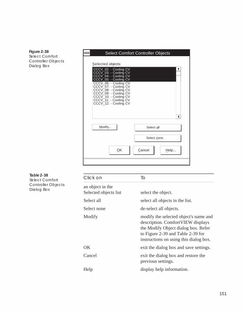
151
Click on To
an object in theSelected objects list select the object.
Select all select all objects in the list.
Select none de-select all objects.
Modify modify the selected object's name anddescription. ComfortVIEW displaysthe Modify Object dialog box. Referto Figure 2-39 and Table 2-39 forinstructions on using this dialog box.
OK exit the dialog box and save settings.
Cancel exit the dialog box and restore theprevious settings.
Help display help information.
Figure 2-38Select ComfortController ObjectsDialog Box
CCCV_02: - Cooling CVCCCV_03: - Cooling CVCCCV_04: - Cooling CVCCCV_05: - Cooling CV
Select Comfort Controller Objects
Selected objects:
CCCV_06: - Cooling CVCCCV_07: - Cooling CVCCCV_08: - Cooling CVCCCV_09: - Cooling CVCCCV_10: - Cooling CVCCCV_11: - Cooling CVCCCV_12: - Cooling CV
Modify... Select all
Select none
OK Cancel Help...
Table 2-38Select ComfortController ObjectsDialog Box
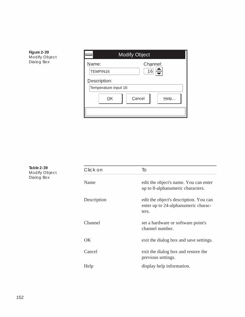
152
Figure 2-39Modify ObjectDialog Box
Click on To
Name edit the object's name. You can enterup to 8-alphanumeric characters.
Description edit the object's description. You canenter up to 24-alphanumeric charac-ters.
Channel set a hardware or software point'schannel number.
OK exit the dialog box and save settings.
Cancel exit the dialog box and restore theprevious settings.
Help display help information.
Table 2-39Modify ObjectDialog Box
Modify Object
Description:
Name:
OK Cancel Help...
16
Channel:
TEMPIN16
Temperature input 16
153
Follow the instructions below to configure a Comfort Controllerobject.
Prior to beginning this procedure, you must create the object. Ifnecessary, refer to Creating and Modifying Hardware and SoftwarePoints or Creating and Modifying Other Database Objects: Set-points, System Tables, Alarms, Functions, Algorithms for instruc-tions on creating objects. These instructions appear earlier in thisConfiguring Comfort Controllers section.
1. Display the object's configuration table.
Note: ComfortVIEW automatically displays the configura-tion table as the last step in the new point or objectcreation process. You can also display an object'sconfiguration table at any time by clicking on theConfigure Comfort Controller tabbed dialog box'sConfigure button, or by selecting the configurationtable from the expanded controller list.
2. Modify the configuration table data as desired. For detailedinstructions on modifying configuration tables, refer to theModifying Configuration Table Values section of this chap-ter.
Note: Be sure to Save each table modification. If you areoperating on-line with a Comfort Controller, down-load your table modifications to the Comfort Con-troller.
In certain configuration tables, you may notice amagenta (pink) shading on point names and descrip-tions. This shading indicates the availability ofComfortVIEW List Entry (F7) feature. List Entry isdesigned to expedite the configuration process.Refer below to List Entry for instructions on usingthis feature.
The presence of magenta shading on a point name indicates that theList Entry feature is available. This feature helps expedite theconfiguration process by presenting a list of available entries for aconfiguration decision. If a configuration decision's point name anddescription text includes a magenta (pink) shading, you can use thistimesaving feature by following the steps below.
1. In the configuration table worksheet, position the cursor onthe magenta-shaded Name or Description cell.
Configuring DatabaseObjects
List Entry
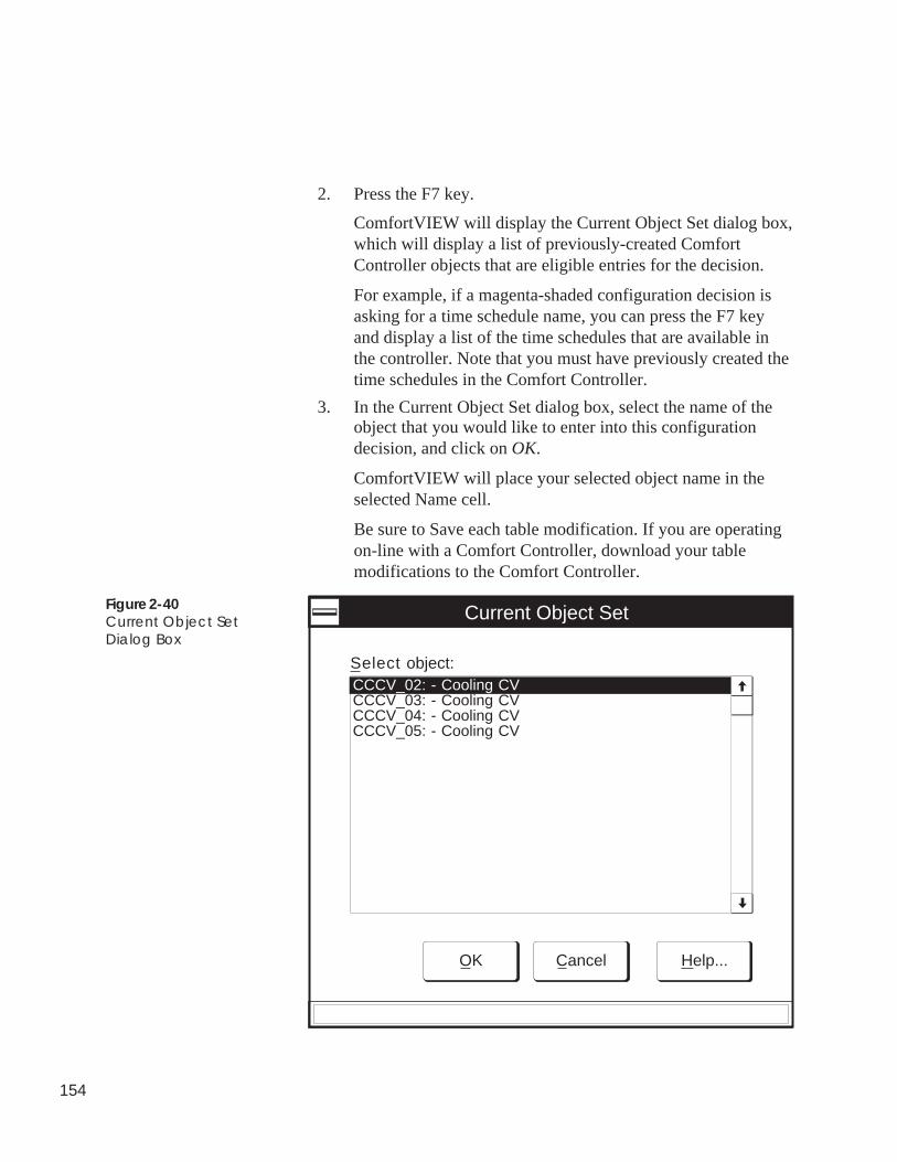
154
2. Press the F7 key.
ComfortVIEW will display the Current Object Set dialog box,which will display a list of previously-created ComfortController objects that are eligible entries for the decision.
For example, if a magenta-shaded configuration decision isasking for a time schedule name, you can press the F7 keyand display a list of the time schedules that are available inthe controller. Note that you must have previously created thetime schedules in the Comfort Controller.
3. In the Current Object Set dialog box, select the name of theobject that you would like to enter into this configurationdecision, and click on OK.
ComfortVIEW will place your selected object name in theselected Name cell.
Be sure to Save each table modification. If you are operatingon-line with a Comfort Controller, download your tablemodifications to the Comfort Controller.
Figure 2-40Current Object SetDialog Box
CCCV_02: - Cooling CVCCCV_03: - Cooling CVCCCV_04: - Cooling CVCCCV_05: - Cooling CV
Current Object Set
Select object:
OK Cancel Help...
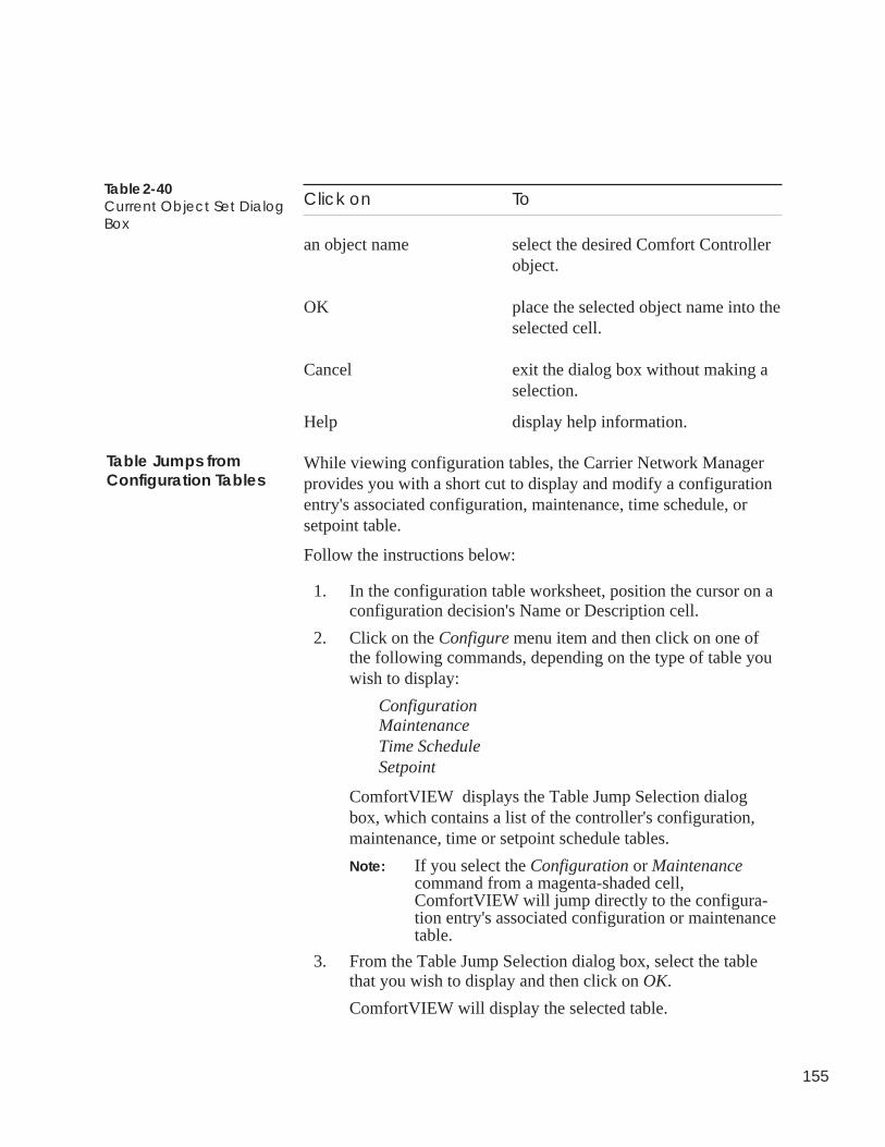
155
Click on To
an object name select the desired Comfort Controllerobject.
OK place the selected object name into theselected cell.
Cancel exit the dialog box without making aselection.
Help display help information.
While viewing configuration tables, the Carrier Network Managerprovides you with a short cut to display and modify a configurationentry's associated configuration, maintenance, time schedule, orsetpoint table.
Follow the instructions below:
1. In the configuration table worksheet, position the cursor on aconfiguration decision's Name or Description cell.
2. Click on the Configure menu item and then click on one ofthe following commands, depending on the type of table youwish to display:
ConfigurationMaintenanceTime ScheduleSetpoint
ComfortVIEW displays the Table Jump Selection dialogbox, which contains a list of the controller's configuration,maintenance, time or setpoint schedule tables.
Note: If you select the Configuration or Maintenancecommand from a magenta-shaded cell,ComfortVIEW will jump directly to the configura-tion entry's associated configuration or maintenancetable.
3. From the Table Jump Selection dialog box, select the tablethat you wish to display and then click on OK.
ComfortVIEW will display the selected table.
Table 2-40Current Object Set DialogBox
Table Jumps fromConfiguration Tables
156
While viewing configuration tables, the Carrier Network Managerprovides you with a means to list the names of all Comfort Control-ler objects that are using the selected configuration entry in theirconfiguration. This feature, however, is available only for thoseconfiguration decisions that contain a magenta (pink) highlighting.
To display a configuration entry's associated objects:
1. In the configuration table worksheet, position the cursor onthe magenta-highlighted Name or Description cell for theconfiguration decision.
2. Click on the Configure menu item and then click onReference tables.ComfortVIEW displays the Table Jump Selection dialog box,which contains a list of all Comfort Controller object tablesthat use the selected configuration point.
3. If desired, you can display a selected object's associatedconfiguration or maintenance table by following the stepsbelow:
a. Click on the object name.
b. Click on Configuration or Maintenance.
c. Click on OK.
ComfortVIEW will display the selected configuration ormaintenance table.
Reference Jumpsfrom ConfigurationTables
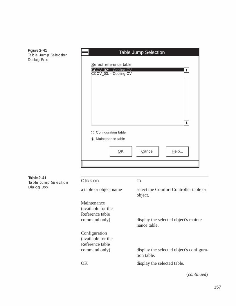
157
Click on To
a table or object name select the Comfort Controller table orobject.
Maintenance(available for theReference tablecommand only) display the selected object's mainte-
nance table.
Configuration(available for theReference tablecommand only) display the selected object's configura-
tion table.
OK display the selected table.
(continued)
Table 2-41Table Jump SelectionDialog Box
Figure 2-41Table Jump SelectionDialog Box
CCCV_02: - Cooling CVCCCV_03: - Cooling CV
Table Jump Selection
Select reference table:
OK Cancel Help...
Configuration table
Maintenance table
158
Click on To
Cancel exit the dialog box without making aselection.
Help display help information.
As with all other controllers, you use the Download command tosend configuration table data to the Comfort Controller. You candownload the entire controller or only a single configuration table.
When you download an entire Comfort Controller, ComfortVIEWsends data from its database to the controller. You can optionallyre-program the entire Comfort Controller with the ComfortVIEWdatabase data, or preserve the Comfort Controller data and add onlynew or revised objects in the Comfort Controller database.
To Download a Specific Table: To download a specific ComfortController configuration table, display the configuration table andclick on the Configure menu item and then click on Download.
Note: You may also perform this command by clicking on theDownload icon in the toolbar.
ComfortVIEW sends the configuration shown on-screen to thecontroller. It overwrites the controller's current configuration.
To Download an Entire Comfort Controller:
1. Display the Controller List window and select the ComfortController whose configuration you wish to download.
2. Click on the Configure menu item and then click on Down-load.
Note: You may also perform this command by clicking onthe Download icon in the toolbar.
ComfortVIEW displays a message dialog box with the ques-tion Should the Comfort Controller be initialized?
3. Clicking on Yes will cause the entire Comfort Controllerdatabase to be re-programmed with the configuration con-tained in the ComfortVIEW database.
Table 2-41Table Jump SelectionDialog Box(continued)
DownloadingComfortVIEW Data toa Comfort Controller
159
Clicking on No will cause the existing Comfort Controllerdatabase to be preserved and will add only new or revisedobjects that do not yet exist in the Comfort Controller data-base.
Caution: If you answer Yes, all controller outputs will be-come unconfigured (disabled) for the period of timethat it takes to complete the download and re-programming. If you answer No, all controlleroutputs will be held at their last commanded state asyour new objects are added and as any object modi-fication are made.
A function status box displays during the download process.The controller list re-displays on successful completion. Ifthere are errors encountered during the download, a dialogbox displays indicating that errors were encountered. If youwish to view an error report, click on Yes. This opens theWindows Notepad application and displays the error report.
Recovering from Download Errors:
A typical Comfort Controller download failure indicates that one ormore Comfort Controller objects could not be created. Typically,these errors mean that you have run out of available memory spacein the Comfort Controller. Follow the steps below to examine thedatabase status of your Comfort Controller:
1. Display the Controller List window and click on the control-ler that you have just attempted to download.
2. Click on the Configure menu item and then click on Controller.
ComfortVIEW displays the Configure Comfort Controllerdialog box.
3. Click on the dialog box's Database status button.
ComfortVIEW displays the Database Status dialog box. Referto Table 2-42 for an explanation of the fields in this dialogbox and recommended actions.
160
Field Value Recommended Action
Database error Yes Examine available bytes ofmemory. If the Comfort Controlleris near 100% utilization for eithercategory, it is likely that the objectsthat you have tried to create wouldnot fit into available ComfortController memory space.ComfortVIEW discontinues theobject creation process if you runout of controller memory. To clearthis error, delete one of the existingobjects. Free memory space for thecreation of additional objects bydeleting less important objects. Ifthe Comfort Controller has anexisting Database Error, do NOTupload the Comfort Controller toComfortVIEW. You risk losingyour last known good configuration.
EEPROM error Yes Follow instructions for Databaseerror. If condition persists, reset theComfort Controller using the RJ-14reset jumper. If the Comfort Con-troller has an existing EEPROMError, do NOT upload the ComfortController to ComfortVIEW. Yourisk losing your last known goodconfiguration.
RAM error Yes Follow instructions for Databaseerror. If condition persists, reset theComfort Controller using the RJ-14reset jumper. If the Comfort Con-troller has an existing RAM Error,do NOT upload thea ComfortController to ComfortVIEW. Yourisk losing your last known goodconfiguration.
Table 2-42Database Status DialogBox and RecommendedActions
161
Viewing or ModifyingBEST++ Tables
Follow the instructions below to directly access and view BEST++maintenance and configuration table program variables. You mustbe communicating (operating on-line) with the Comfort Controllerin order to access these BEST++ tables.
1. Display the System Overview window and expand it todisplay the database’s CCNs and areas. If necessary, followthe instructions listed under Accessing the Carrier NetworkManager.
2. Display the controller list. If necessary, follow the instruc-tions listed under Displaying the Controller List.
3. Double click on a controller to view its table categories.
4. Double click on BEST++ Tables.
5. In the right half of the window, double click on BEST++Program List. ComfortVIEW displays the BEST++ Programsdialog box. Refer to Figure and Table 2-42A for instructionson using this dialog box.
Note: You must be communicating with the ComfortController to access these tables.
6. In the BEST++ Programs dialog box, select the BEST++program and then click on Configuration table or Mainte-nance table and OK to display the corresponding BEST++table.
7. You can modify BEST++ configuration table or force mainte-nance table data. If necessary, refer to the Modifying Con-figuration Table Values or Modifying (Forcing) Status Dis-play or Maintenance Table Values section of this chapter forinstructions.
Note: Be sure to Save and Download any configurationtable modifications.
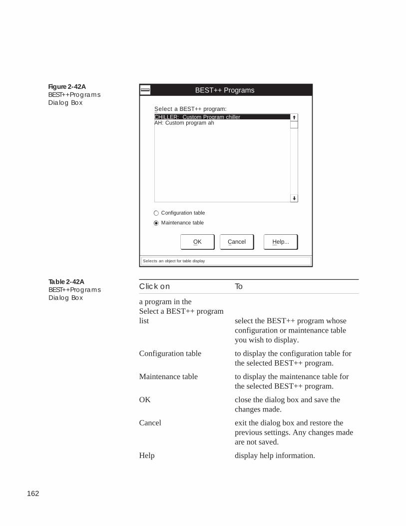
162
Figure 2-42ABEST++ProgramsDialog Box
CHILLER: Custom Program chillerAH: Custom program ah
BEST++ Programs
Select a BEST++ program:
OK Cancel Help...
Configuration table
Maintenance table
Selects an object for table display
Table 2-42ABEST++ProgramsDialog Box
Click on To
a program in theSelect a BEST++ programlist select the BEST++ program whose
configuration or maintenance tableyou wish to display.
Configuration table to display the configuration table forthe selected BEST++ program.
Maintenance table to display the maintenance table forthe selected BEST++ program.
OK close the dialog box and save thechanges made.
Cancel exit the dialog box and restore theprevious settings. Any changes madeare not saved.
Help display help information.
163
ComfortVIEW gives you the capability to back up an entirecontroller’s database to another directory, sub-directory, or drive.You should make it a practice to periodically back up your control-ler database in the event that a malfunction should occur with yourhard disk.
Export copies the selected controller’s entire database to the speci-fied drive. This drive can be the ComfortVIEW floppy diskettedrive, another ComfortVIEW hard drive partition, or another com-puter on the local area network. The information that will be copiedincludes:
• the controller name, description, and address• configuration data.
This database information can be copied back, or imported toComfortVIEW at any time, using the Configure menu’s New com-mand. For additional information, refer to the Adding/ModifyingControllers section of this chapter.
ComfortVIEW also gives you the capability to back up an entireCCN's database. For instructions on this function, refer to ExportingCCNs in the Setup chapter of this manual.
Follow the instructions below to export a controller’s database fromthe ComfortVIEW hard disk. You can export single or multiplecontrollers:
1. Display the Controller List window. If necessary, follow theinstructions listed under Displaying the Controller List.
2. Click on the controller you wish to export.
Note: You can also export multiple controllers. Use theWindows-standard mouse or keyboard technique toselect multiple controllers from the right side of thewindow.
3. Click on File and then click on Export.
Note: You may also perform this command by clicking onthe Export icon in the toolbar.
ComfortVIEW will display either the Save As dialog box orthe Select Directory dialog box, depending on whether youhave selected a single or multiple controllers.
ExportingController
ConfigurationData
164
4. Do one of the following depending on whether you wish toexport a single or multiple controllers:
To export a single controller:
In the File Name edit box, enter a file name for the controllerexport file. Use the file extension .CWX, and select thedirectory and drive where you want the file saved. Refer toTable 2-43 for more information on using the Save As dialogbox.
Note: If you want to save the file to another computer onthe local area network, click on Network.
ComfortVIEW displays the Connect Network Drive dialogbox. Select the pre-defined drive and path to where you wishto save the file, or double click on a computer in the SharedDirectories list and select the desired directory.
To export multiple controllers:
Select the directory path where you wish to save the file.ComfortVIEW will save the export file to this directory usingthe following file naming convention: BxxxCyyy.CWX,where xxx is the bus number and yyy is the system elementnumber.
5. Click on OK to save the file to the specified file name andlocation.
ComfortVIEW displays a dialog box asking for confirmationbefore copying the selected controller. Click on Yes to com-plete the export, or click on No to prevent the export fromtaking place. If you have selected multiple controllers andwish to export all, click on Yes to All.
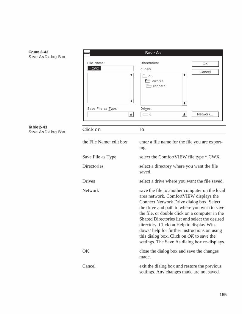
165
Figure 2-43Save As Dialog Box
Click on To
the File Name: edit box enter a file name for the file you are export-ing.
Save File as Type select the ComfortVIEW file type *.CWX.
Directories select a directory where you want the filesaved.
Drives select a drive where you want the file saved.
Network save the file to another computer on the localarea network. ComfortVIEW displays theConnect Network Drive dialog box. Selectthe drive and path to where you wish to savethe file, or double click on a computer in theShared Directories list and select the desireddirectory. Click on Help to display Win-dows’ help for further instructions on usingthis dialog box. Click on OK to save thesettings. The Save As dialog box re-displays.
OK close the dialog box and save the changesmade.
Cancel exit the dialog box and restore the previoussettings. Any changes made are not saved.
Table 2-43Save As Dialog Box
File Name:
Network...
Save As
OK
Cancel*.CWX
Save File as Type: Drives:
d:
d:\
cworks
ccnpath
d:\bsiv
Directories:
166
DedicatingAutodialGateways to aSpecificOperation
If you have more than one Autodial Gateway in a selected CCN, youcan, if desired, reserve selected Gateways to perform the followingoperations:
• Timed data retrieval — Reserves the selected Gateway for usewhen connecting to remote CCNs to perform automatic timed dataretrieval for ComfortVIEW reports.
• Standard connection — Reserves the selected Gateway for usewhen manually connecting to remote CCNs.
• Receipt of Incoming alarms — Reserves the selected Gateway foruse when receiving incoming alarms.
• Transmission of Outgoing alarms — Reserves the selected Gate-way for use when sending outgoing alarms.
Keep in mind that reserving an Autodial Gateway for a particularoperation does not prevent ComfortVIEW from using the Gateway forother operations. It only allows ComfortVIEW to make the bestpossible selection under the given conditions.
This option is not available if you are using an internal Gateway forremote CCN communication.
Note: Reserving a Gateway for a particular operation is entirelyoptional. If you do not make specific operational assign-ments, ComfortVIEW automatically selects an idle Gatewayfor use.
Follow the steps below to assign operations to Autodial Gateways:
1. Display the Carrier Network Manager’s System Overviewwindow and expand it to display the database’s CCNs andareas. If necessary, follow the instructions listed under Access-ing the Carrier Network Manager.
2. Click on the CCN whose Autodial Gateways you wish toassign.
3. Click on the CCN Tools menu item and then click on Gateways.
ComfortVIEW displays the Gateway Configuration dialog box(shown in Figure 2-44). This box lists the name and descriptionof all Gateways in the selected CCN.
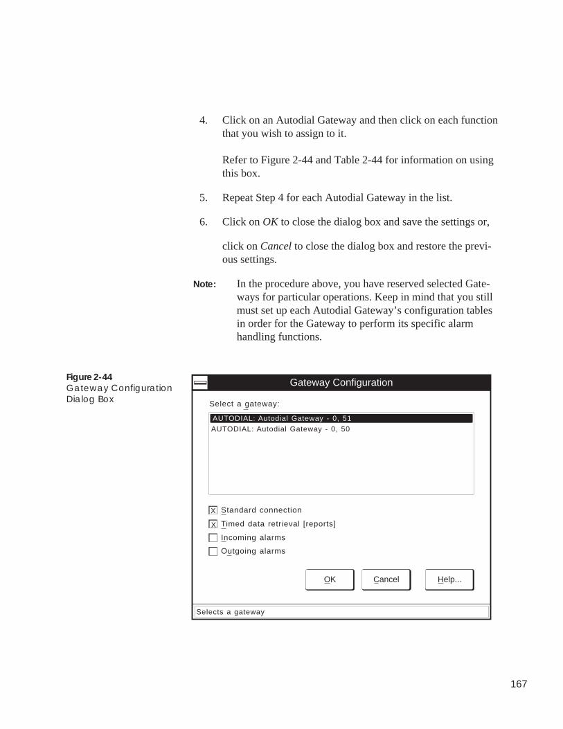
167
4. Click on an Autodial Gateway and then click on each functionthat you wish to assign to it.
Refer to Figure 2-44 and Table 2-44 for information on usingthis box.
5. Repeat Step 4 for each Autodial Gateway in the list.
6. Click on OK to close the dialog box and save the settings or,
click on Cancel to close the dialog box and restore the previ-ous settings.
Note: In the procedure above, you have reserved selected Gate-ways for particular operations. Keep in mind that you stillmust set up each Autodial Gateway’s configuration tablesin order for the Gateway to perform its specific alarmhandling functions.
Figure 2-44Gateway ConfigurationDialog Box Select a gateway:
Standard connection
Gateway Configuration
AUTODIAL: Autodial Gateway - 0, 51
OK Cancel Help...
Timed data retrieval [reports]
Incoming alarms
Outgoing alarms
AUTODIAL: Autodial Gateway - 0, 50
X
X
Selects a gateway
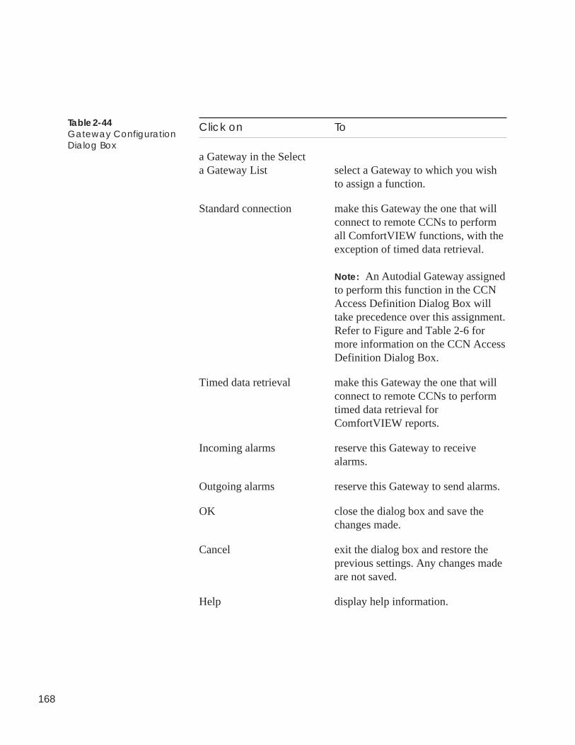
168
Table 2-44Gateway ConfigurationDialog Box
Click on To
a Gateway in the Selecta Gateway List select a Gateway to which you wish
to assign a function.
Standard connection make this Gateway the one that willconnect to remote CCNs to performall ComfortVIEW functions, with theexception of timed data retrieval.
Note: An Autodial Gateway assignedto perform this function in the CCNAccess Definition Dialog Box willtake precedence over this assignment.Refer to Figure and Table 2-6 formore information on the CCN AccessDefinition Dialog Box.
Timed data retrieval make this Gateway the one that willconnect to remote CCNs to performtimed data retrieval forComfortVIEW reports.
Incoming alarms reserve this Gateway to receivealarms.
Outgoing alarms reserve this Gateway to send alarms.
OK close the dialog box and save thechanges made.
Cancel exit the dialog box and restore theprevious settings. Any changes madeare not saved.
Help display help information.
169
Connecting
to a Remote
CCN Using an
Autodial
Gateway
Follow the steps below to establish a telephone connection to aremote CCN:
1. Display the Carrier Network Manager’s System Overviewwindow and expand it to display the database’s CCNs. Ifnecessary, follow the instructions listed under Accessing theCarrier Network Manager.
2. Click on the remote CCN with which you wish to communi-cate. In the System Overview window, remote CCNs arepreceded by an icon as shown at left.
3. Click on the Access menu item and then click on Connect.
Note: You may also perform this command by clicking onthe Connect icon in the toolbar.
ComfortVIEW displays a confirmation dialog box asking ifyou wish to connect to the selected CCN(s).
Note: If you have only one Autodial Gateway on yourCCN and are currently connected to another remoteCCN, ComfortVIEW displays a message indicatingthat you are unable to connect. Click on OK to closethe message dialog box.
4. Click on Yes to connect or click on No to prevent the connectfrom taking place.
You are now connected to the remote CCN. The status area to theright of the toolbar displays the connect status. You can now use allComfortVIEW applications and functions as if you were connectedlocally. If, in the Setup application, you have the Setup menu'sRemote status command enabled, the names of all CCNs to whichyou are currently connected will display in the Setup's application'sComfortVIEW Remote Connections window.
You could now use the CCN Tools, Bus Services command to obtaina list of all system elements on the remote CCN. For further infor-mation on the Bus Services command, refer to the Carrier NetworkManager Command Summary, which appears at the end of thischapter.
170
Follow the steps below to disconnect from a remote CCN:
Note : You can disconnect while displaying either the System Over-view or the Controller List window. If you are disconnectingfrom the System Overview window, however, you must clickon the remote CCN from which you wish to disconnect priorto performing the instructions below.
1. Click on the Access menu item and then click on Disconnect.
Note: ComfortVIEW will display the message CCN Is In Useand you will not be permitted to disconnect if anotheroperator is currently viewing a status display or mainte-nance table in the remote CCN.
ComfortVIEW displays a confirmation dialog box asking if youwish to disconnect to the selected CCN(s).
2. Click on Yes to disconnect or click on No to prevent the discon-nect from taking place.
When you are disconnected from the remote CCN, the status line dis-plays Disconnect.
Be aware that ComfortVIEW automatically disconnects you from aremote CCN if, after an operator-specified number of minutes, nocommunication occurs. The Autodial Gateway will generate an alarm tonotify you of an automatic disconnect. For additional information on theautomatic disconnect feature, refer to the explanation of the PhoneNumber Configuration dialog box in the Adding and Modifying CCNssection of this chapter.
Disconnectingfrom RemoteCCNs
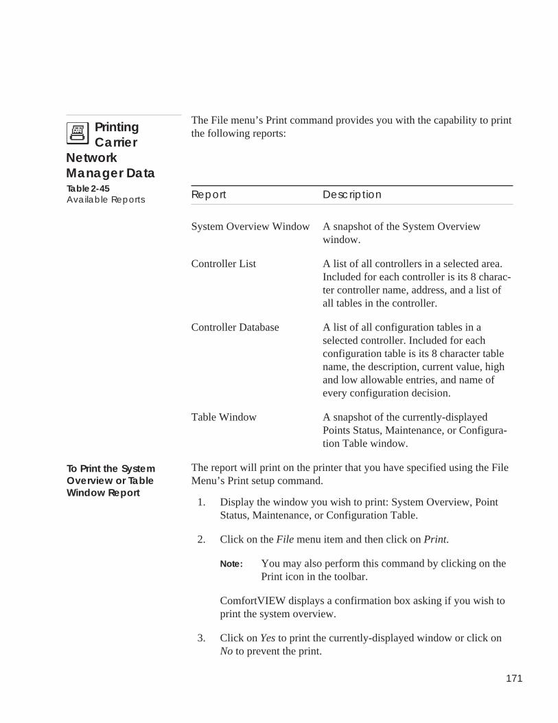
171
The File menu’s Print command provides you with the capability to printthe following reports:
Report Description
System Overview Window A snapshot of the System Overviewwindow.
Controller List A list of all controllers in a selected area.Included for each controller is its 8 charac-ter controller name, address, and a list ofall tables in the controller.
Controller Database A list of all configuration tables in aselected controller. Included for eachconfiguration table is its 8 character tablename, the description, current value, highand low allowable entries, and name ofevery configuration decision.
Table Window A snapshot of the currently-displayedPoints Status, Maintenance, or Configura-tion Table window.
The report will print on the printer that you have specified using the FileMenu’s Print setup command.
1. Display the window you wish to print: System Overview, PointStatus, Maintenance, or Configuration Table.
2. Click on the File menu item and then click on Print.
Note: You may also perform this command by clicking on thePrint icon in the toolbar.
ComfortVIEW displays a confirmation box asking if you wish toprint the system overview.
3. Click on Yes to print the currently-displayed window or click onNo to prevent the print.
PrintingCarrier
NetworkManager DataTable 2-45Available Reports
To Print the SystemOverview or TableWindow Report
172
1. Display the Controller List window. If necessary, follow the instruc-tions listed under Displaying the Controller List.
2. Click on the area name in the window.
3. Click on the File menu item and then click on Print. ComfortVIEWdisplays a confirmation box asking if you wish to print the areaelement list.
Note: You may also perform this command by clicking on thePrint icon in the toolbar.
4. Click on Yes to print the list of all controllers in the selected area, orclick on No to prevent the print. The controller list report prints onyour ComfortVIEW printer. Figure 2-46 displays a sample controllerlist report.
1. Display the Controller List window. If necessary, follow the instruc-tions listed under Displaying the Controller List.
2. Click on the controller whose database you wish to print.
Note: You can also select and print reports on multiple control-lers. Use the Windows-standard mouse or keyboard tech-niques to select multiple controllers. You can, however,only select multiple controllers from the right side of theController List window.
3. Click on the File menu item and then click on Print. ComfortVIEWdisplays a confirmation box asking if you wish to create the databasereport.
Note: You may also perform this command by clicking on thePrint icon in the toolbar.
4. Click on Yes to create the report, or click on No to prevent reportcreation. ComfortVIEW creates the report and displays it using theWindows Notepad application.
5. To print the report, click on Notepad’s File menu item and then clickon Print.
6. To close the report file, click on Notepad’s File menu item and thenclick on Exit.
To Print a ControllerList Report
To Print a ControllerDatabase Report
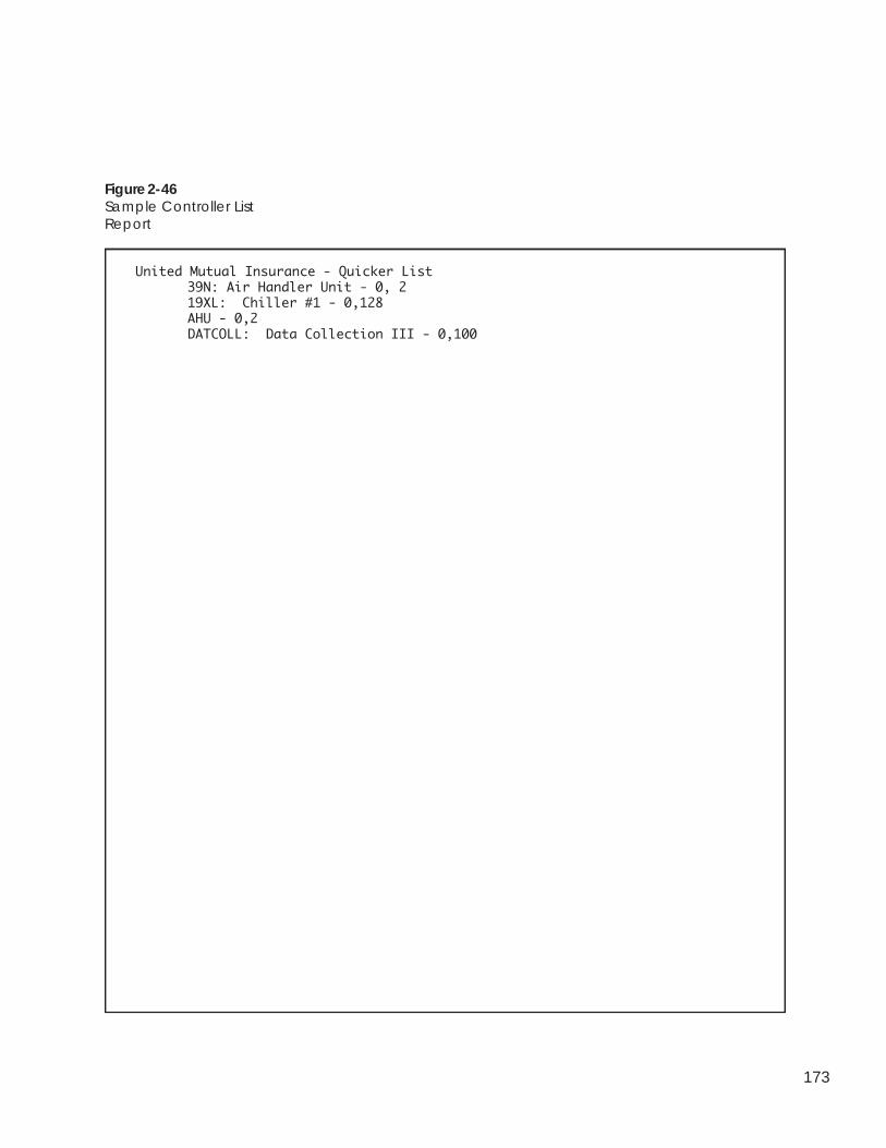
173
Figure 2-46Sample Controller ListReport
United Mutual Insurance - Quicker List39N: Air Handler Unit - 0, 219XL: Chiller #1 - 0,128AHU - 0,2DATCOLL: Data Collection III - 0,100
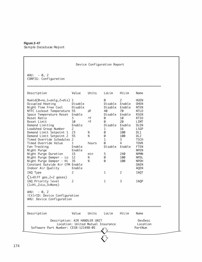
174
Figure 2-47Sample Database Report
Device Configuration Report
AHU: - 0, 2CONFIG: Configuration
===========================================================================
Description Value Units LoLim HiLim Name
Humid(0=no,1=anlg,2=dis) 1 0 2 HUENOccupied Heating Disable Disable Enable OHENNight Time Free Cool Disable Disable Enable NTENNTFC Lockout Temperature 55 dF 40 70 NTLOSpace Temperature Reset Enable Disable Enable RSENReset Ratio 3 ^F 0 10 RTIOReset Limit 10 ^F 0 20 LIMTDemand Limiting Enable Disable Enable DLENLoadshed Group Number 2 1 16 LSGPDemand Limit Setpoint 1 23 % 0 100 DL1Demand Limit Setpoint 2 55 % 0 100 DL2Timed Override Schedules 2 1 3 TSCHTimed Override Value 1 hours 0 4 TOVRFan Tracking Enable Disable Enable FTENNight Purge Enable NPENNight Purge Duration 15 min 5 240 NPMNNight Purge Damper - Lo 12 % 0 100 NPDLNight Purge Damper - Hi 35 % 0 100 NPDHConstant Outside Air CFM Enable OAENIndoor Air Quality Enable AQEN
IAQ Type 2 1 2 IAQT
(1=Diff gas,2=2 gases)IAQ Priority level 2 1 3 IAQP(1=Hi,2=Lo,3=None)
AHU: - 0, 2!CtlrID: Device ConfigurationAHU: Device Configuration
===========================================================================
Description Value Units LoLim HiLim Name
Description: AIR HANDLER UNIT DevDescLocation: United Mutual Insurance Location
Software Part Number: CESR-121498-05 PartNum
175
You can send real time CCN system element data fromComfortVIEW to other PC software applications that are running onyour ComfortVIEW workstation. This is accomplished usingComfortVIEW Dynamic Data Exchange (DDE) feature. The PCsoftware application to which you intend to send data must supportDDE. You set up DDE links between ComfortVIEW and the otherPC software application in order to send the data.
You can also use another PC application that supports DDE "poke"to override forceable CCN point values. Refer below to DDE Pokefor further information on this feature.
• Controller point data
The following controller point data will be sent any time there isa change in the data:
Point descriptionPoint valuePoint unitsPoint statusPoint force status
• The most recently received Carrier Comfort Network alarm
The following alarm data can be sent:
Alarm message and associated custom alarm messageAlarm message onlyCustom alarm message only
• The application that is to receive the data must be linked to theappropriate ComfortVIEW data point. See Linking ControllerPoint Data to Applications that Support Paste Link, LinkingController Point Data to Applications that Do Not Support PasteLink, and Linking Alarm Messages to Other Applicationsbelow.
• You must be logged in to ComfortVIEW
• The dynamic data must be changing in order to receive anupdate in the linked application.
One application that supports DDE, is Microsoft’s Excel spread-sheet program. To send data from ComfortVIEW to Excel you mustestablish a DDE link between the two applications. This link is
SharingComfortVIEWDynamic Datawith OtherApplications(DDE)
What Data can beSent?
Linking ControllerPoint Data toApplications thatSupport Paste Link
Required Conditionsfor Successful DataSharing
176
easily established using commands available in the ComfortVIEWand Excel menu structures.
To establish a DDE link, use each application’s Copy and Pastecommands as follows:
1. Launch your Excel spreadsheet program and open a newworksheet.
2. Launch the Carrier Network Manager application and accessthe controller whose data you wish to share.
3. Select the controller’s status or maintenance display table andopen the table for display.
4. Find the point that you wish to use.
5. Use the mouse to select the point’s description, point value,units, or force status.
Note: You can select one, or all of the point’s fields.Toselect all of the fields and to include the time of thelast point update, click on the button to the left of thepoint description and select the entire row. You canonly select one point at a time.
6. Click on the Edit menu item and then click on Copy.
7. Simultaneously press the Alt and Tab keys to switch to yourExcel application.
8. Select the cell that you wish to link to your selectedComfortVIEW point data. When pasting an entire row, select arange of cells equal to the number being copied fromComfortVIEW.
9. Click on Excel’s Edit menu item and then click on PasteSpecial and Link.
10. Your selected ComfortVIEW point data will appear in theappropriate worksheet cells.
If the application to which you are linking does not support the PasteLink function, you must specify the ComfortVIEW DDE link infor-mation manually. Use your application’s specified method for creat-ing programmed DDE links.
To link ComfortVIEW data, you must specify the following linkinformation in the DDE-supported application for each piece of
Linking ControllerPoint Data toApplications that DoNot Support Paste Link
177
ComfortVIEW data you wish to read:
• ComfortVIEW application name — ComfortWORKS• Topic Name — See Table 2-47 for topic names of available
ComfortVIEW point information. You will notice that there aretwo topic names included in this table. Use the name shown inparentheses if the ComfortVIEW table is not currently open fordisplay.
• Item Reference Number — Point ID Number
To display the point ID number, click on the Carrier NetworkManager’s Options menu item and then click on Point IDs. Thenumber will display in the Name column following the 8 charac-ter point name.
Data Topic Name
Description PntDesc (CCNPntDesc)Point Value PntValue (CCNPntValue)Units PntUnits (CCNPntUnits)Status PntStatus (CCNPntStatus)Force Status PntFrcStatus (CCNPntFrcStatus)All of the above PntAll (CCNPntAll)
Example of Excel's requirements for creating programmed DDEpoint data links.
You would enter DDE point data link information in an Excelcell in the format shown below. Note that this format variesdependent on the PC application to which you are linking.
=ComfortWORKS|Topic Name!’ Item Reference Number’
Example of Excel’s actual cell formula (where theComfortVIEW table from which you are linking is currentlyopen): =ComfortWORKS|PntAll!’35304'
Explanation:The Excel spreadsheet will be able to read the following data forthe ComfortVIEW point that corresponds to item number 35304:Description, Point Value, Units, Status, and Force Status.
Table 2-47ComfortVIEW TopicNames
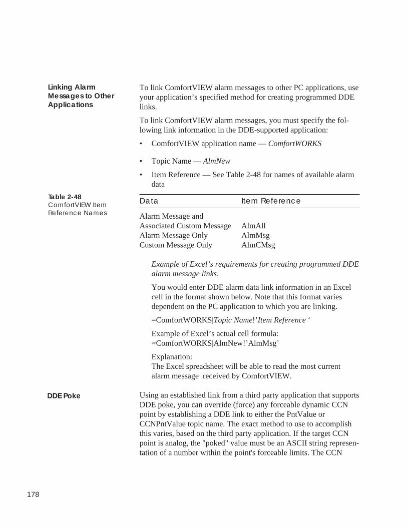
178
To link ComfortVIEW alarm messages to other PC applications, useyour application’s specified method for creating programmed DDElinks.
To link ComfortVIEW alarm messages, you must specify the fol-lowing link information in the DDE-supported application:
• ComfortVIEW application name — ComfortWORKS
• Topic Name — AlmNew
• Item Reference — See Table 2-48 for names of available alarmdata
Data Item Reference
Alarm Message andAssociated Custom Message AlmAllAlarm Message Only AlmMsgCustom Message Only AlmCMsg
Example of Excel’s requirements for creating programmed DDEalarm message links.
You would enter DDE alarm data link information in an Excelcell in the format shown below. Note that this format variesdependent on the PC application to which you are linking.
=ComfortWORKS|Topic Name!’ Item Reference ‘
Example of Excel’s actual cell formula:=ComfortWORKS|AlmNew!’AlmMsg’
Explanation:The Excel spreadsheet will be able to read the most currentalarm message received by ComfortVIEW.
Using an established link from a third party application that supportsDDE poke, you can override (force) any forceable dynamic CCNpoint by establishing a DDE link to either the PntValue orCCNPntValue topic name. The exact method to use to accomplishthis varies, based on the third party application. If the target CCNpoint is analog, the "poked" value must be an ASCII string represen-tation of a number within the point's forceable limits. The CCN
Linking AlarmMessages to OtherApplications
Table 2-48ComfortVIEW ItemReference Names
DDE Poke
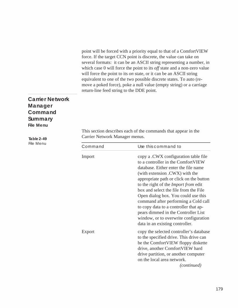
179
point will be forced with a priority equal to that of a ComfortVIEWforce. If the target CCN point is discrete, the value can take onseveral formats: it can be an ASCII string representing a number, inwhich case 0 will force the point to its off state and a non-zero valuewill force the point to its on state, or it can be an ASCII stringequivalent to one of the two possible discrete states. To auto (re-move a poked force), poke a null value (empty string) or a carriagereturn-line feed string to the DDE point.
This section describes each of the commands that appear in theCarrier Network Manager menus.
Command Use this command to
Import copy a .CWX configuration table fileto a controller in the ComfortVIEWdatabase. Either enter the file name(with extension .CWX) with theappropriate path or click on the buttonto the right of the Import from editbox and select the file from the FileOpen dialog box. You could use thiscommand after performing a Cold callto copy data to a controller that ap-pears dimmed in the Controller Listwindow, or to overwrite configurationdata in an existing controller.
Export copy the selected controller’s databaseto the specified drive. This drive canbe the ComfortVIEW floppy diskettedrive, another ComfortVIEW harddrive partition, or another computeron the local area network.
(continued)
Carrier NetworkManagerCommandSummaryFile Menu
Table 2-49File Menu
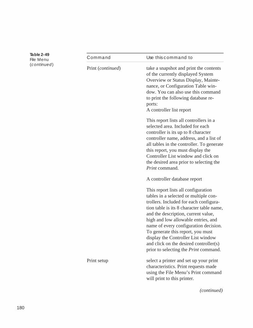
180
Command Use this command to
Print (continued) take a snapshot and print the contentsof the currently displayed SystemOverview or Status Display, Mainte-nance, or Configuration Table win-dow. You can also use this commandto print the following database re-ports:A controller list report
This report lists all controllers in aselected area. Included for eachcontroller is its up to 8 charactercontroller name, address, and a list ofall tables in the controller. To generatethis report, you must display theController List window and click onthe desired area prior to selecting thePrint command.
A controller database report
This report lists all configurationtables in a selected or multiple con-trollers. Included for each configura-tion table is its 8 character table name,and the description, current value,high and low allowable entries, andname of every configuration decision.To generate this report, you mustdisplay the Controller List windowand click on the desired controller(s)prior to selecting the Print command.
Print setup select a printer and set up your printcharacteristics. Print requests madeusing the File Menu’s Print commandwill print to this printer.
(continued)
Table 2-49File Menu(continued)
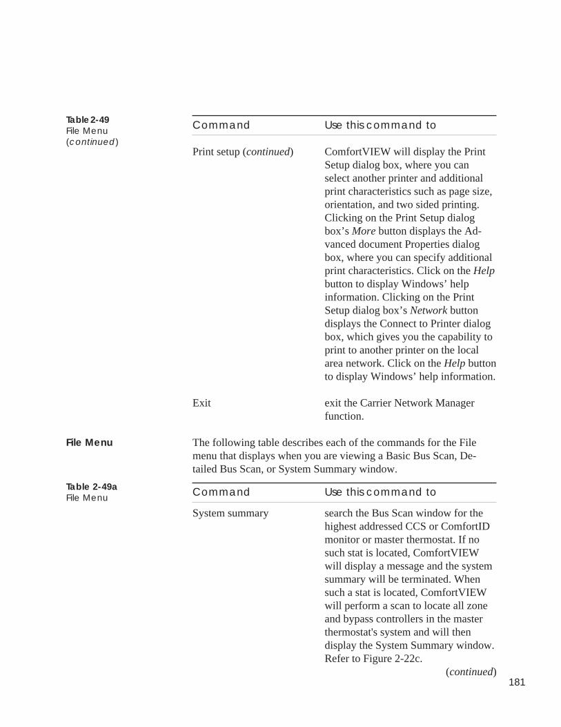
181
Command Use this command to
Print setup (continued) ComfortVIEW will display the PrintSetup dialog box, where you canselect another printer and additionalprint characteristics such as page size,orientation, and two sided printing.Clicking on the Print Setup dialogbox’s More button displays the Ad-vanced document Properties dialogbox, where you can specify additionalprint characteristics. Click on the Helpbutton to display Windows’ helpinformation. Clicking on the PrintSetup dialog box’s Network buttondisplays the Connect to Printer dialogbox, which gives you the capability toprint to another printer on the localarea network. Click on the Help buttonto display Windows’ help information.
Exit exit the Carrier Network Managerfunction.
The following table describes each of the commands for the Filemenu that displays when you are viewing a Basic Bus Scan, De-tailed Bus Scan, or System Summary window.
Command Use this command to
System summary search the Bus Scan window for thehighest addressed CCS or ComfortIDmonitor or master thermostat. If nosuch stat is located, ComfortVIEWwill display a message and the systemsummary will be terminated. Whensuch a stat is located, ComfortVIEWwill perform a scan to locate all zoneand bypass controllers in the masterthermostat's system and will thendisplay the System Summary window.Refer to Figure 2-22c.
(continued)
Table 2-49File Menu(continued)
File Menu
Table 2-49aFile Menu
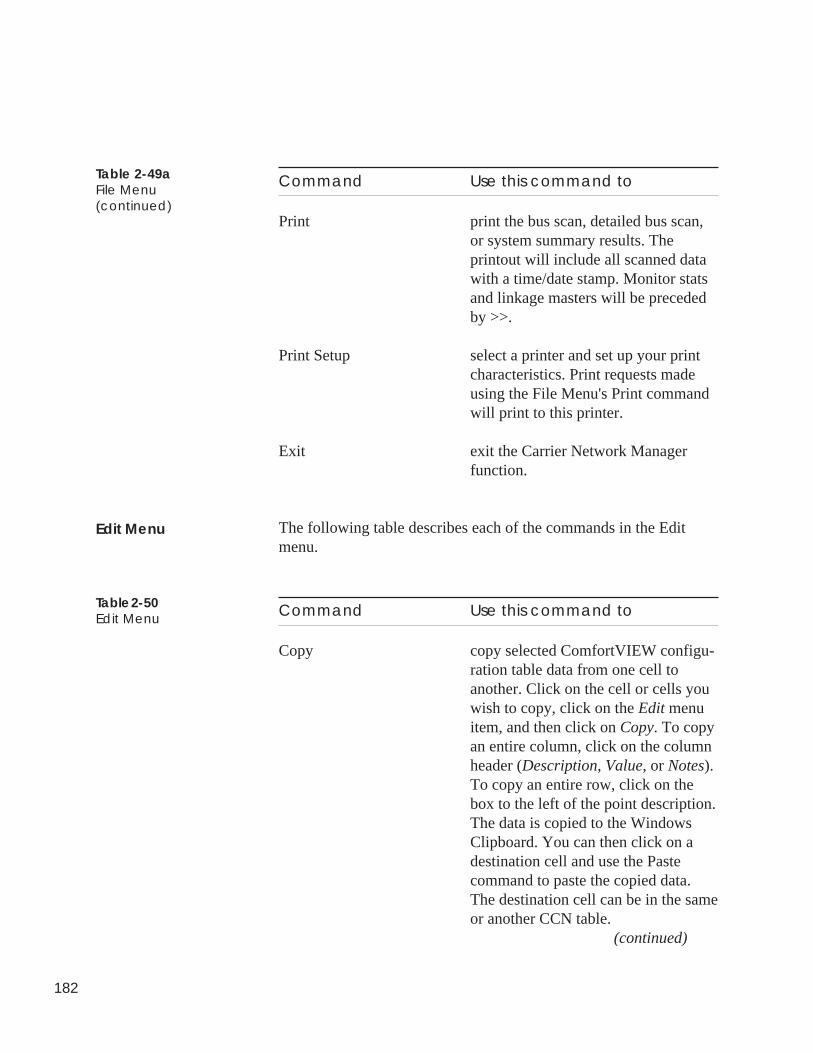
182
Command Use this command to
Print print the bus scan, detailed bus scan,or system summary results. Theprintout will include all scanned datawith a time/date stamp. Monitor statsand linkage masters will be precededby >>.
Print Setup select a printer and set up your printcharacteristics. Print requests madeusing the File Menu's Print commandwill print to this printer.
Exit exit the Carrier Network Managerfunction.
The following table describes each of the commands in the Editmenu.
Command Use this command to
Copy copy selected ComfortVIEW configu-ration table data from one cell toanother. Click on the cell or cells youwish to copy, click on the Edit menuitem, and then click on Copy. To copyan entire column, click on the columnheader (Description, Value, or Notes).To copy an entire row, click on thebox to the left of the point description.The data is copied to the WindowsClipboard. You can then click on adestination cell and use the Pastecommand to paste the copied data.The destination cell can be in the sameor another CCN table.
(continued)
Edit Menu
Table 2-50Edit Menu
Table 2-49aFile Menu(continued)
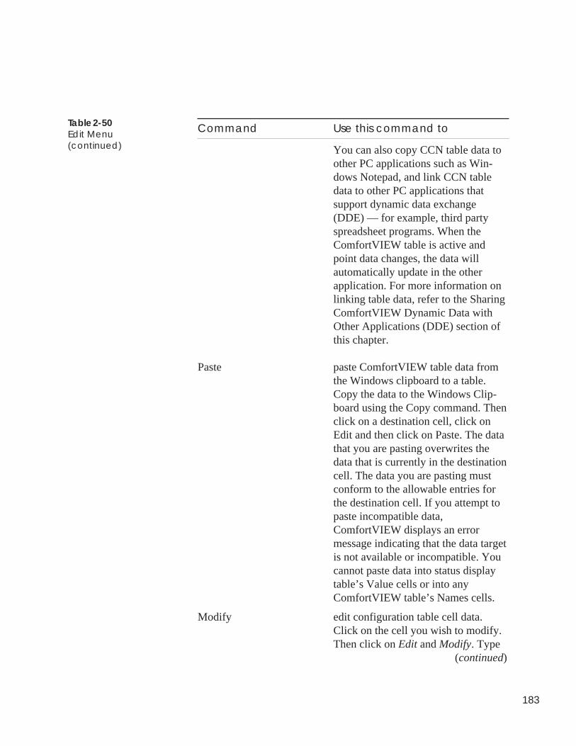
183
Table 2-50Edit Menu(continued)
Command Use this command to
You can also copy CCN table data toother PC applications such as Win-dows Notepad, and link CCN tabledata to other PC applications thatsupport dynamic data exchange(DDE) — for example, third partyspreadsheet programs. When theComfortVIEW table is active andpoint data changes, the data willautomatically update in the otherapplication. For more information onlinking table data, refer to the SharingComfortVIEW Dynamic Data withOther Applications (DDE) section ofthis chapter.
Paste paste ComfortVIEW table data fromthe Windows clipboard to a table.Copy the data to the Windows Clip-board using the Copy command. Thenclick on a destination cell, click onEdit and then click on Paste. The datathat you are pasting overwrites thedata that is currently in the destinationcell. The data you are pasting mustconform to the allowable entries forthe destination cell. If you attempt topaste incompatible data,ComfortVIEW displays an errormessage indicating that the data targetis not available or incompatible. Youcannot paste data into status displaytable’s Value cells or into anyComfortVIEW table’s Names cells.
Modify edit configuration table cell data.Click on the cell you wish to modify.Then click on Edit and Modify. Type
(continued)
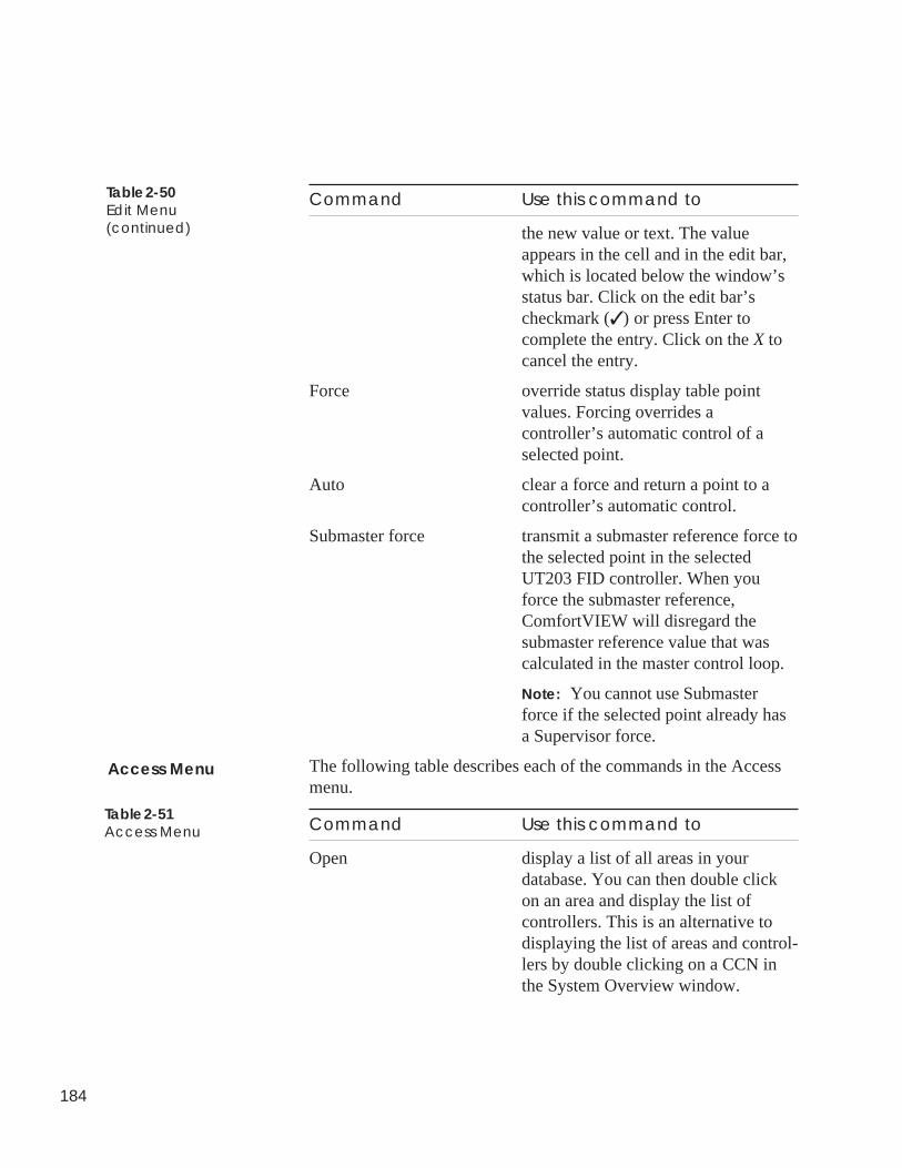
184
Command Use this command to
the new value or text. The valueappears in the cell and in the edit bar,which is located below the window’sstatus bar. Click on the edit bar’scheckmark (✓ ) or press Enter tocomplete the entry. Click on the X tocancel the entry.
Force override status display table pointvalues. Forcing overrides acontroller’s automatic control of aselected point.
Auto clear a force and return a point to acontroller’s automatic control.
Submaster force transmit a submaster reference force tothe selected point in the selectedUT203 FID controller. When youforce the submaster reference,ComfortVIEW will disregard thesubmaster reference value that wascalculated in the master control loop.
Note: You cannot use Submasterforce if the selected point already hasa Supervisor force.
The following table describes each of the commands in the Accessmenu.
Command Use this command to
Open display a list of all areas in yourdatabase. You can then double clickon an area and display the list ofcontrollers. This is an alternative todisplaying the list of areas and control-lers by double clicking on a CCN inthe System Overview window.
Table 2-50Edit Menu(continued)
Table 2-51Access Menu
Access Menu
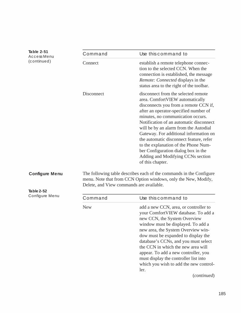
185
Command Use this command to
Connect establish a remote telephone connec-tion to the selected CCN. When theconnection is established, the messageRemote: Connected displays in thestatus area to the right of the toolbar.
Disconnect disconnect from the selected remotearea. ComfortVIEW automaticallydisconnects you from a remote CCN if,after an operator-specified number ofminutes, no communication occurs.Notification of an automatic disconnectwill be by an alarm from the AutodialGateway. For additional information onthe automatic disconnect feature, referto the explanation of the Phone Num-ber Configuration dialog box in theAdding and Modifying CCNs sectionof this chapter.
The following table describes each of the commands in the Configuremenu. Note that from CCN Option windows, only the New, Modify,Delete, and View commands are available.
Command Use this command to
New add a new CCN, area, or controller toyour ComfortVIEW database. To add anew CCN, the System Overviewwindow must be displayed. To add anew area, the System Overview win-dow must be expanded to display thedatabase’s CCNs, and you must selectthe CCN in which the new area willappear. To add a new controller, youmust display the controller list intowhich you wish to add the new control-ler.
(continued)
Configure Menu
Table 2-52Configure Menu
Table 2-51Access Menu(continued)
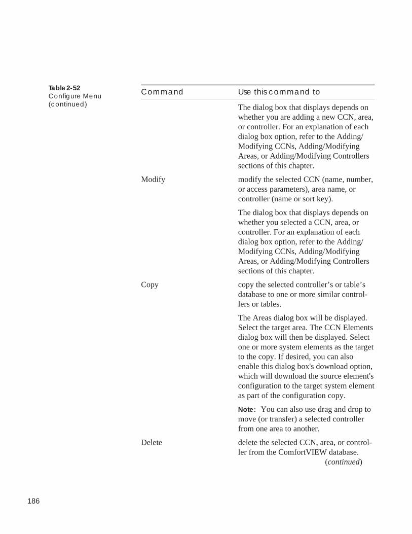
186
Table 2-52Configure Menu(continued)
Command Use this command to
The dialog box that displays depends onwhether you are adding a new CCN, area,or controller. For an explanation of eachdialog box option, refer to the Adding/Modifying CCNs, Adding/ModifyingAreas, or Adding/Modifying Controllerssections of this chapter.
Modify modify the selected CCN (name, number,or access parameters), area name, orcontroller (name or sort key).
The dialog box that displays depends onwhether you selected a CCN, area, orcontroller. For an explanation of eachdialog box option, refer to the Adding/Modifying CCNs, Adding/ModifyingAreas, or Adding/Modifying Controllerssections of this chapter.
Copy copy the selected controller’s or table’sdatabase to one or more similar control-lers or tables.
The Areas dialog box will be displayed.Select the target area. The CCN Elementsdialog box will then be displayed. Selectone or more system elements as the targetto the copy. If desired, you can alsoenable this dialog box's download option,which will download the source element'sconfiguration to the target system elementas part of the configuration copy.
Note: You can also use drag and drop tomove (or transfer) a selected controllerfrom one area to another.
Delete delete the selected CCN, area, or control-ler from the ComfortVIEW database.
(continued)
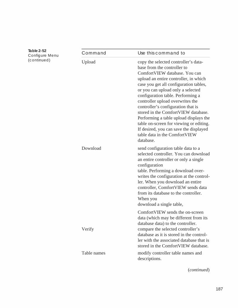
187
Command Use this command to
Upload copy the selected controller’s data-base from the controller toComfortVIEW database. You canupload an entire controller, in whichcase you get all configuration tables,or you can upload only a selectedconfiguration table. Performing acontroller upload overwrites thecontroller’s configuration that isstored in the ComfortVIEW database.Performing a table upload displays thetable on-screen for viewing or editing.If desired, you can save the displayedtable data in the ComfortVIEWdatabase.
Download send configuration table data to aselected controller. You can downloadan entire controller or only a singleconfigurationtable. Performing a download over-writes the configuration at the control-ler. When you download an entirecontroller, ComfortVIEW sends datafrom its database to the controller.When youdownload a single table,
ComfortVIEW sends the on-screendata (which may be different from itsdatabase data) to the controller.
Verify compare the selected controller’sdatabase as it is stored in the control-ler with the associated database that isstored in the ComfortVIEW database.
Table names modify controller table names anddescriptions.
(continued)
Table 2-52Configure Menu(continued)
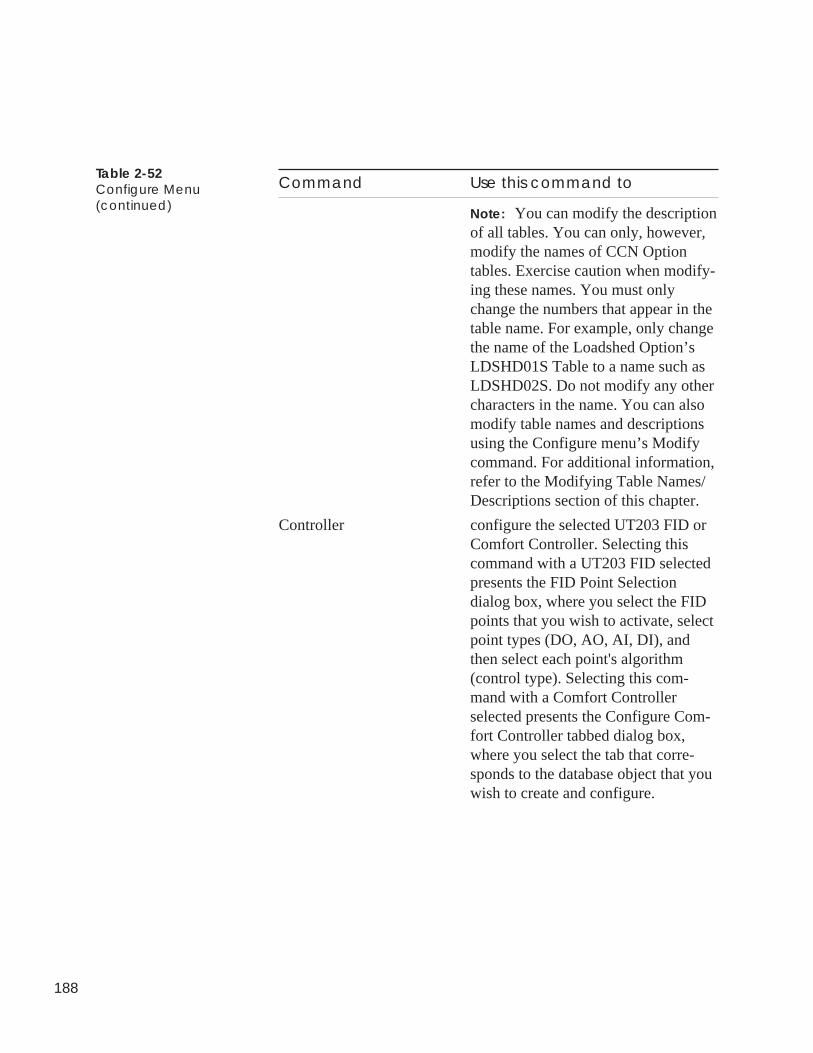
188
Command Use this command to
Note: You can modify the descriptionof all tables. You can only, however,modify the names of CCN Optiontables. Exercise caution when modify-ing these names. You must onlychange the numbers that appear in thetable name. For example, only changethe name of the Loadshed Option’sLDSHD01S Table to a name such asLDSHD02S. Do not modify any othercharacters in the name. You can alsomodify table names and descriptionsusing the Configure menu’s Modifycommand. For additional information,refer to the Modifying Table Names/Descriptions section of this chapter.
Controller configure the selected UT203 FID orComfort Controller. Selecting thiscommand with a UT203 FID selectedpresents the FID Point Selectiondialog box, where you select the FIDpoints that you wish to activate, selectpoint types (DO, AO, AI, DI), andthen select each point's algorithm(control type). Selecting this com-mand with a Comfort Controllerselected presents the Configure Com-fort Controller tabbed dialog box,where you select the tab that corre-sponds to the database object that youwish to create and configure.
Table 2-52Configure Menu(continued)
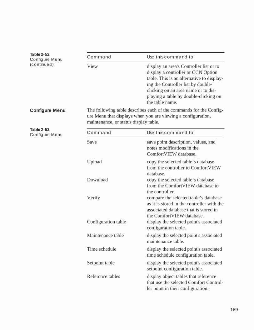
189
Command Use this command to
View display an area's Controller list or todisplay a controller or CCN Optiontable. This is an alternative to display-ing the Controller list by double-clicking on an area name or to dis-playing a table by double-clicking onthe table name.
The following table describes each of the commands for the Config-ure Menu that displays when you are viewing a configuration,maintenance, or status display table.
Command Use this command to
Save save point description, values, andnotes modifications in theComfortVIEW database.
Upload copy the selected table’s databasefrom the controller to ComfortVIEWdatabase.
Download copy the selected table’s databasefrom the ComfortVIEW database tothe controller.
Verify compare the selected table’s databaseas it is stored in the controller with theassociated database that is stored inthe ComfortVIEW database.
Configuration table display the selected point's associatedconfiguration table.
Maintenance table display the selected point's associatedmaintenance table.
Time schedule display the selected point's associatedtime schedule configuration table.
Setpoint table display the selected point's associatedsetpoint configuration table.
Reference tables display object tables that referencethat use the selected Comfort Control-ler point in their configuration.
Table 2-52Configure Menu(continued)
Configure Menu
Table 2-53Configure Menu
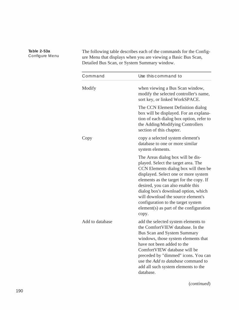
190
The following table describes each of the commands for the Config-ure Menu that displays when you are viewing a Basic Bus Scan,Detailed Bus Scan, or System Summary window.
Command Use this command to
Modify when viewing a Bus Scan window,modify the selected controller's name,sort key, or linked WorkSPACE.
The CCN Element Definition dialogbox will be displayed. For an explana-tion of each dialog box option, refer tothe Adding/Modifying Controllerssection of this chapter.
Copy copy a selected system element'sdatabase to one or more similarsystem elements.
The Areas dialog box will be dis-played. Select the target area. TheCCN Elements dialog box will then bedisplayed. Select one or more systemelements as the target for the copy. Ifdesired, you can also enable thisdialog box's download option, whichwill download the source element'sconfiguration to the target systemelement(s) as part of the configurationcopy.
Add to database add the selected system elements tothe ComfortVIEW database. In theBus Scan and System Summarywindows, those system elements thathave not been added to theComfortVIEW database will bepreceded by "dimmed" icons. You canuse the Add to database command toadd all such system elements to thedatabase.
(continued)
Table 2-53aConfigure Menu
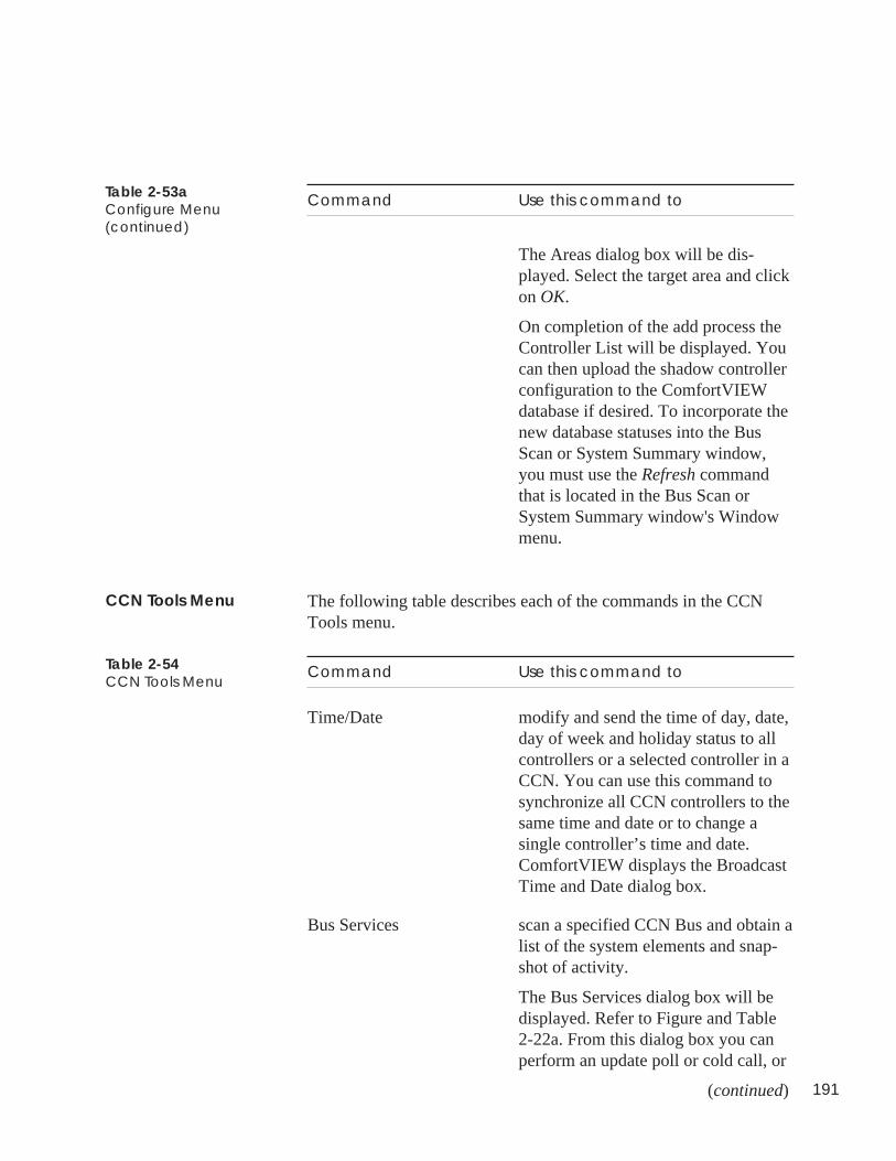
191
Command Use this command to
The Areas dialog box will be dis-played. Select the target area and clickon OK.
On completion of the add process theController List will be displayed. Youcan then upload the shadow controllerconfiguration to the ComfortVIEWdatabase if desired. To incorporate thenew database statuses into the BusScan or System Summary window,you must use the Refresh commandthat is located in the Bus Scan orSystem Summary window's Windowmenu.
The following table describes each of the commands in the CCNTools menu.
Command Use this command to
Time/Date modify and send the time of day, date,day of week and holiday status to allcontrollers or a selected controller in aCCN. You can use this command tosynchronize all CCN controllers to thesame time and date or to change asingle controller’s time and date.ComfortVIEW displays the BroadcastTime and Date dialog box.
Bus Services scan a specified CCN Bus and obtain alist of the system elements and snap-shot of activity.
The Bus Services dialog box will bedisplayed. Refer to Figure and Table2-22a. From this dialog box you canperform an update poll or cold call, or
(continued)
Table 2-53aConfigure Menu(continued)
CCN Tools Menu
Table 2-54CCN Tools Menu
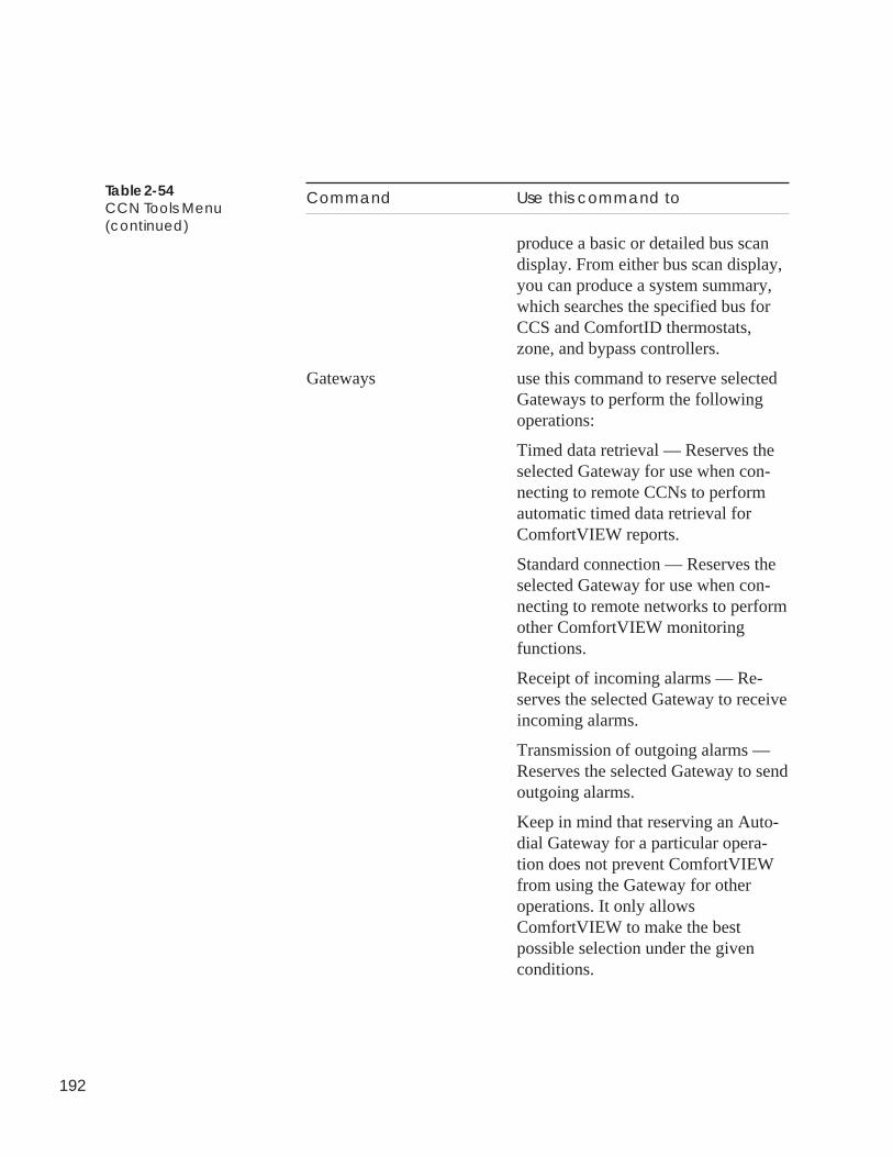
192
Table 2-54CCN Tools Menu(continued)
Command Use this command to
produce a basic or detailed bus scandisplay. From either bus scan display,you can produce a system summary,which searches the specified bus forCCS and ComfortID thermostats,zone, and bypass controllers.
Gateways use this command to reserve selectedGateways to perform the followingoperations:
Timed data retrieval — Reserves theselected Gateway for use when con-necting to remote CCNs to performautomatic timed data retrieval forComfortVIEW reports.
Standard connection — Reserves theselected Gateway for use when con-necting to remote networks to performother ComfortVIEW monitoringfunctions.
Receipt of incoming alarms — Re-serves the selected Gateway to receiveincoming alarms.
Transmission of outgoing alarms —Reserves the selected Gateway to sendoutgoing alarms.
Keep in mind that reserving an Auto-dial Gateway for a particular opera-tion does not prevent ComfortVIEWfrom using the Gateway for otheroperations. It only allowsComfortVIEW to make the bestpossible selection under the givenconditions.
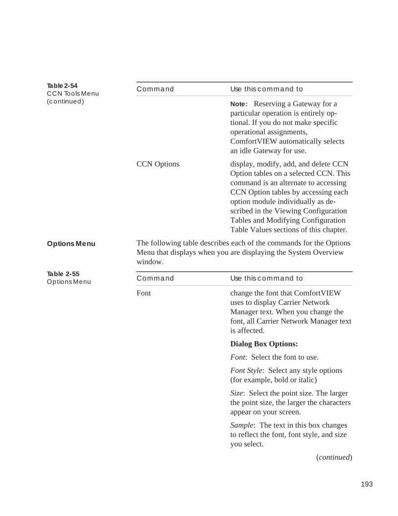
193
Table 2-54CCN Tools Menu(continued)
Command Use this command to
Note: Reserving a Gateway for aparticular operation is entirely op-tional. If you do not make specificoperational assignments,ComfortVIEW automatically selectsan idle Gateway for use.
CCN Options display, modify, add, and delete CCNOption tables on a selected CCN. Thiscommand is an alternate to accessingCCN Option tables by accessing eachoption module individually as de-scribed in the Viewing ConfigurationTables and Modifying ConfigurationTable Values sections of this chapter.
The following table describes each of the commands for the OptionsMenu that displays when you are displaying the System Overviewwindow.
Command Use this command to
Font change the font that ComfortVIEWuses to display Carrier NetworkManager text. When you change thefont, all Carrier Network Manager textis affected.
Dialog Box Options:
Font: Select the font to use.
Font Style: Select any style options(for example, bold or italic)
Size: Select the point size. The largerthe point size, the larger the charactersappear on your screen.
Sample: The text in this box changesto reflect the font, font style, and sizeyou select.
(continued)
Table 2-55Options Menu
Options Menu
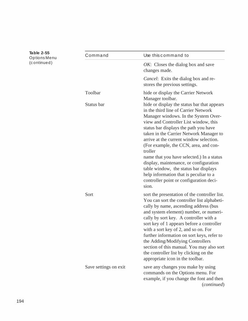
194
Command Use this command to
OK: Closes the dialog box and savechanges made.
Cancel: Exits the dialog box and re-stores the previous settings.
Toolbar hide or display the Carrier NetworkManager toolbar.
Status bar hide or display the status bar that appearsin the third line of Carrier NetworkManager windows. In the System Over-view and Controller List window, thisstatus bar displays the path you havetaken in the Carrier Network Manager toarrive at the current window selection.(For example, the CCN, area, and con-trollername that you have selected.) In a statusdisplay, maintenance, or configurationtable window, the status bar displayshelp information that is peculiar to acontroller point or configuration deci-sion.
Sort sort the presentation of the controller list.You can sort the controller list alphabeti-cally by name, ascending address (busand system element) number, or numeri-cally by sort key. A controller with asort key of 1 appears before a controllerwith a sort key of 2, and so on. Forfurther information on sort keys, refer tothe Adding/Modifying Controllerssection of this manual. You may also sortthe controller list by clicking on theappropriate icon in the toolbar.
Save settings on exit save any changes you make by usingcommands on the Options menu. Forexample, if you change the font and then
(continued)
Table 2-55Options Menu(continued)
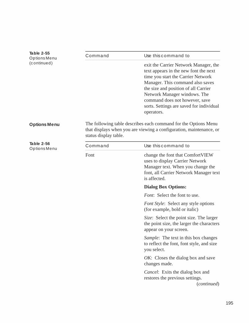
195
Command Use this command to
exit the Carrier Network Manager, thetext appears in the new font the nexttime you start the Carrier NetworkManager. This command also savesthe size and position of all CarrierNetwork Manager windows. Thecommand does not however, savesorts. Settings are saved for individualoperators.
The following table describes each command for the Options Menuthat displays when you are viewing a configuration, maintenance, orstatus display table.
Command Use this command to
Font change the font that ComfortVIEWuses to display Carrier NetworkManager text. When you change thefont, all Carrier Network Manager textis affected.
Dialog Box Options:
Font: Select the font to use.
Font Style: Select any style options(for example, bold or italic)
Size: Select the point size. The largerthe point size, the larger the charactersappear on your screen.
Sample: The text in this box changesto reflect the font, font style, and sizeyou select.
OK: Closes the dialog box and savechanges made.
Cancel: Exits the dialog box andrestores the previous settings.
(continued)
Table 2-55Options Menu(continued)
Table 2-56Options Menu
Options Menu
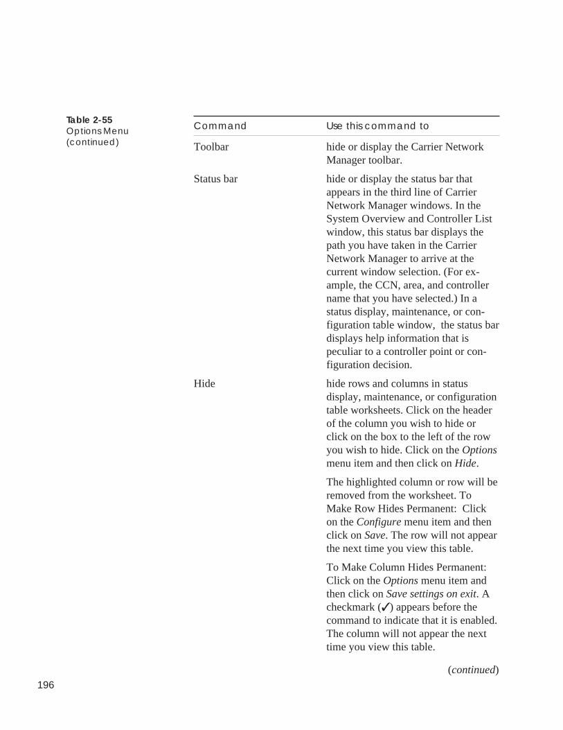
196
Command Use this command to
Toolbar hide or display the Carrier NetworkManager toolbar.
Status bar hide or display the status bar thatappears in the third line of CarrierNetwork Manager windows. In theSystem Overview and Controller Listwindow, this status bar displays thepath you have taken in the CarrierNetwork Manager to arrive at thecurrent window selection. (For ex-ample, the CCN, area, and controllername that you have selected.) In astatus display, maintenance, or con-figuration table window, the status bardisplays help information that ispeculiar to a controller point or con-figuration decision.
Hide hide rows and columns in statusdisplay, maintenance, or configurationtable worksheets. Click on the headerof the column you wish to hide orclick on the box to the left of the rowyou wish to hide. Click on the Optionsmenu item and then click on Hide.
The highlighted column or row will beremoved from the worksheet. ToMake Row Hides Permanent: Clickon the Configure menu item and thenclick on Save. The row will not appearthe next time you view this table.
To Make Column Hides Permanent:Click on the Options menu item andthen click on Save settings on exit. Acheckmark (✓ ) appears before thecommand to indicate that it is enabled.The column will not appear the nexttime you view this table.
(continued)
Table 2-55Options Menu(continued)
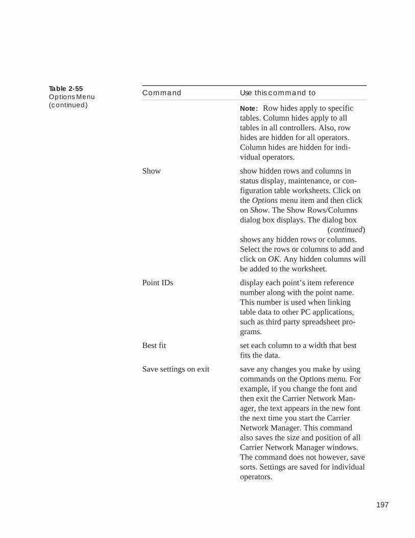
197
Command Use this command to
Note: Row hides apply to specifictables. Column hides apply to alltables in all controllers. Also, rowhides are hidden for all operators.Column hides are hidden for indi-vidual operators.
Show show hidden rows and columns instatus display, maintenance, or con-figuration table worksheets. Click onthe Options menu item and then clickon Show. The Show Rows/Columnsdialog box displays. The dialog box
(continued)shows any hidden rows or columns.Select the rows or columns to add andclick on OK. Any hidden columns willbe added to the worksheet.
Point IDs display each point’s item referencenumber along with the point name.This number is used when linkingtable data to other PC applications,such as third party spreadsheet pro-grams.
Best fit set each column to a width that bestfits the data.
Save settings on exit save any changes you make by usingcommands on the Options menu. Forexample, if you change the font andthen exit the Carrier Network Man-ager, the text appears in the new fontthe next time you start the CarrierNetwork Manager. This commandalso saves the size and position of allCarrier Network Manager windows.The command does not however, savesorts. Settings are saved for individualoperators.
Table 2-55Options Menu(continued)
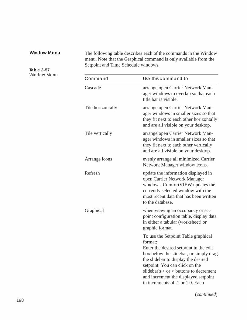
198
The following table describes each of the commands in the Windowmenu. Note that the Graphical command is only available from theSetpoint and Time Schedule windows.
Command Use this command to
Cascade arrange open Carrier Network Man-ager windows to overlap so that eachtitle bar is visible.
Tile horizontally arrange open Carrier Network Man-ager windows in smaller sizes so thatthey fit next to each other horizontallyand are all visible on your desktop.
Tile vertically arrange open Carrier Network Man-ager windows in smaller sizes so thatthey fit next to each other verticallyand are all visible on your desktop.
Arrange icons evenly arrange all minimized CarrierNetwork Manager window icons.
Refresh update the information displayed inopen Carrier Network Managerwindows. ComfortVIEW updates thecurrently selected window with themost recent data that has been writtento the database.
Graphical when viewing an occupancy or set-point configuration table, display datain either a tabular (worksheet) orgraphic format.
To use the Setpoint Table graphicalformat:Enter the desired setpoint in the editbox below the slidebar, or simply dragthe slidebar to display the desiredsetpoint. You can click on theslidebar's < or > buttons to decrementand increment the displayed setpointin increments of .1 or 1.0. Each
(continued)
Table 2-57Window Menu
Window Menu
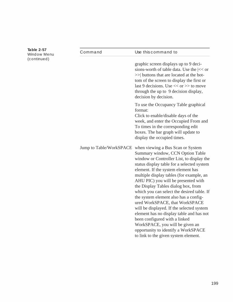
199
Command Use this command to
graphic screen displays up to 9 deci-sions-worth of table data. Use the |<< or>>| buttons that are located at the bot-tom of the screen to display the first orlast 9 decisions. Use << or >> to movethrough the up to 9 decision display,decision by decision.
To use the Occupancy Table graphicalformat:Click to enable/disable days of theweek, and enter the Occupied From andTo times in the corresponding editboxes. The bar graph will update todisplay the occupied times.
Jump to Table/WorkSPACE when viewing a Bus Scan or SystemSummary window, CCN Option Tablewindow or Controller List, to display thestatus display table for a selected systemelement. If the system element hasmultiple display tables (for example, anAHU PIC) you will be presented withthe Display Tables dialog box, fromwhich you can select the desired table. Ifthe system element also has a config-ured WorkSPACE, that WorkSPACEwill be displayed. If the selected systemelement has no display table and has notbeen configured with a linkedWorkSPACE, you will be given anopportunity to identify a WorkSPACEto link to the given system element.
Table 2-57Window Menu(continued)
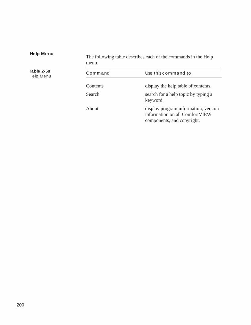
200
The following table describes each of the commands in the Helpmenu.
Command Use this command to
Contents display the help table of contents.
Search search for a help topic by typing akeyword.
About display program information, versioninformation on all ComfortVIEWcomponents, and copyright.
Table 2-58Help Menu
Help Menu
Remote Site Manager

Alarm Manager
201
This chapter provides instructions on ComfortVIEW Remote SiteManager application.
For instructions on... Turn to page
using ComfortVIEW Remote Site Manager 202
verifying required conditions for successful connection 202
connecting to a remote ComfortVIEWServer workstation 205
disconnecting from a remote ComfortVIEWServer workstation 208
adding a site to the ComfortVIEWRemote Site list 209
removing a site from the ComfortVIEWRemote Site list 212
The following terms are used throughout this chapter.
Server — A computer running ComfortVIEW communication, userinterface, service, and database software.
Client — A computer on a local area network runningComfortVIEW communication and user interface software, orComfortVIEW user interface software only.
Remote SiteManager
202
You can use the ComfortVIEW Remote Site Manager application todial in to a remote ComfortVIEW Server. You can dial in from acomputer that is running either ComfortVIEW Server orComfortVIEW Client software. When you dial in to aComfortVIEW Server, your computer and the Server to which youare connected operate as if they were connected on a local areanetwork. All of the capabilities that you would have as a local Clientcomputer are yours when you dial in as a remote Client computer.
Note: The Remote Site Manager application is not available forthe ComfortVIEW Stand-alone installation option.
When you connect to a remote ComfortVIEW Server from a localComfortVIEW Server, the operation of your local Server is unaf-fected. However, any alarms received from the local CCN will notbe visually or audibly indicated. They will still, however, be printedand logged to the database. Your local Server will remain active andwill continue to operate as a Server for the other ComfortVIEWClients on your system.
Note: ComfortVIEW Remote Site Manager application givesyou access to the ComfortVIEW applications of theremote Server. If you want to directly access the Server’sdisk, registry, event log or any other Windows networkingfeatures, you should use the more powerful WindowsNetwork and Dial-up Connections application.
The following conditions must exist for you to successfully dial inand log on to a remote ComfortVIEW Server.
Note: You cannot dial to a remote Server that is running aComfortVIEW version that is greater than the sourceworkstation version.
Source ComfortVIEW Workstation (the Workstation Placing the Call):
Verify that the conditions listed below exist at the workstation thatis placing the call. If they do not, perform the listed instructions atthis workstation.
1. If you wish to dial into a remote Server that is running anearlier version of ComfortWORKS software, you must createa separate bootable partition on your workstation onto whichyou will install the earlier version of ComfortWORKS Client.
Introduction
Required Conditionsfor a SuccessfulConnection
203
For example, to dial into ComfortWORKS Version 4.1 froma ComfortWORKS Version 5.0 workstation, you must createa separate partition and install ComfortWORKS Version 5.0Client.
2. Windows Remote Access Connection Manager Service (Dial-up Networking) software must have been installed along withthe appropriate modem device driver. Refer to your WindowsRemote Access Connection Manager installation instructions.
3. Windows Remote Access Connection Manager (Dial-upNetworking) must be configured to dial out calls (as a mini-mum). See your Windows Remote Access Connection Man-ager (Dial-up Networking) setup instructions.
4. The ComfortVIEW Remote Site Manager application musthave been installed. This application is automatically installedwhen you install your ComfortVIEW software on a computerthat has the Windows Remote Access Connection Manager(Dial-up Networking) installed. You can perform theComfortVIEW installation procedure at any time if you needto load the ComfortVIEW Remote Site Manager application.
5. The modem must be operational. You can verify this byattempting to dial the remote Server using the WindowsRemote Access Connection Manager feature.
Verify that you are using compatible source and remotemodems. It is recommended that you use the same make andmodel modem for both source and remote workstations.
6. The remote ComfortVIEW Server computer name, and theremote Server modem phone number must be added to theComfortVIEW Remote Site Manager dialog box’sComfortVIEW Remote Site list. For instructions, refer to theAdding a Site to the ComfortVIEW Remote Site List sectionof this chapter.
7. You must have a valid login name and password to log on tothe remote Server’s Windows operating system.
204
Remote ComfortVIEW Server (the Workstation Receiving the call):
Verify that the conditions listed below exist at the workstation thatis receiving the call. If they do not, perform the listed instructions atthe workstation that is receiving the call.
1. The remote Server must be turned on and running WindowsXP/2000.
2. Windows Remote Access Connection Manager Service (Dial-up Networking) software must have been installed along withthe appropriate modem device driver. Refer to your WindowsRemote Access Connection Manager Service (Dial-up Net-working) installation instructions.
3. The Windows Remote Access Connection Manager (Dial-upNetworking) must be configured to dial out and receive calls.See your Windows Remote Access Connection ManagerService (Dial-up Networking) setup instructions.
4. You must grant dial-in access permissions to all or selectedusers via the Windows Remote Access Connection ManagerService (Dial-up Networking). See your Windows RemoteAccess Connection Manager Service (Dial-up Networking)setup instructions.
5. The Windows Remote Access Connection Manager Service(Dial-up Networking) must be running.
You can start and run the Remote Access Connection Man-ager Service using the Windows Remote Access ConnectionManager, or you can configure the Remote Access Connec-tion Manager Service (Dial-up Networking) to automaticallystart on XP/2000 boot-up.
To start the service automatically on boot-up:
a. Click on the Start menu, then select Settings, and clickon Control Panel.
b. In the Control Panel window, double click on Adminis-trative Tools and then double click on Services. In theServices list, find and double click on Remote AccessAuto Connection Manager.
205
c. In the Remote Access Connection Manager Propertiesdialog box, select the General tab, and then underStartup Type, select Automatic. Then click on Apply andOK to close the dialog boxes.
6. The modem must be operational when operating under theWindows XP/2000 operating system.
You can verify this by attempting to dial out to anotherWindows XP/2000 computer using the Windows Networkand Dial-up Connections feature, or by dialing out to anactive phone number using the HyperTerminal application inWindows Accessories.
7. The computer names of any users who will be dialing in fromother locations must be entered into the Setup Workstations dialogbox, which appears in the ComfortVIEW Setup application.
8. The Windows login names and passwords of any users whowill be logging in from other locations must be entered intothe Windows operating system.
9. The ComfortVIEW login names and passwords of any userswho will be logging in from other locations must be regis-tered in this ComfortVIEW Server. If necessary, refer to theAdding, Modifying, Deleting Operators section in thismanual’s Setup chapter.
Follow the instructions below to use the ComfortVIEW Remote SiteManager application to dial from a ComfortVIEW Server or Clientto a remote ComfortVIEW Server.
1. Close all active ComfortVIEW applications, and log out ofComfortVIEW.
2. Double click on the ComfortVIEW Remote Site Managericon.
Note: It is not necessary to log in to ComfortVIEW beforerunning this application.
ComfortVIEW launches the Remote Site Manager applica-tion and displays the ComfortVIEW Remote Site Managerdialog box. Refer to Figure 3-1.
Connectingto a Remote
ComfortVIEWServer
206
3. In the ComfortVIEW Remote Sites list, click on the remotesite and then click on Connect.
ComfortVIEW displays two message dialog boxes followedby the Authentication dialog box.
4. Enter the remote Server's Windows XP/2000 user name andpassword, and then click on OK.
ComfortVIEW begins the connection process. The status ofthe connection process will be displayed in a status messagebox and by a series of messages on the bottom of the RemoteSite Manager dialog box.
Once the telephone connection is successfully established,ComfortVIEW attempts to log in to the remote site’s Win-dows operating system using your specified user name andpassword. If the user name or password are not valid, youwill be so notified. Click on Retry to enter a new user nameand password or on Cancel to terminate the connection.
Once ComfortVIEW has successfully logged in to the remotesite’s Windows operating system, you can begin yourComfortVIEW session. Successful connection is indicated bythe presence of the word Connected in the Remote SiteManager dialog box’s status bar.
Note: If you receive an Access Denied message at anytime during the connection process, one of thefollowing conditions exists:
• Your computer name does not exist in theremote Server’s database. See Condition #8under Required Conditions for a SuccessfulConnect.
• There are too many logged in users at theremote site.
• The remote site does not have an access keyattached to the Server workstation’s parallelport.
5. Begin your session by logging in to ComfortVIEW.
If the message RPC Server Unavailable is displayed duringComfortVIEW operation, the remote connection has been lost. Ifthis situation occurs, disconnect from the remote Server and then re-connect.

207
Figure 3-1ComfortVIEW Remote SiteManager Dialog Box
208
1. End your current remote ComfortVIEW session by closing allcurrent ComfortVIEW applications (except theComfortVIEW Remote Site Manager application), then logout of ComfortVIEW.
2. Switch to the ComfortVIEW Remote Site Manager applica-tion.
3. In the ComfortVIEW Remote Site Manager dialog box, clickon Disconnect.
A confirmation dialog box will be displayed.
4. Click on Yes.
5. At the second confirmation dialog box, click on OK toproceed with the disconnect.
ComfortVIEW begins the disconnect process. A statusmessage box shows the status of the disconnect process.
6. The connection has been successfully terminated when theRemote Site Manager dialog box's status bar displays NotConnected.
Disconnectingfrom a RemoteComfortVIEW ServerWorkstation
209
Follow the instructions below to add a new or modify an existingComfortVIEW site.
Note: Modifying an existing remote site name maintains theexisting site name and adds a new site with the modifiedsite name. If desired, you can delete the existing site byfollowing the Deleting a Site from the ComfortVIEWRemote Site List instructions below.
1. Double click on the ComfortVIEW Remote Site Managericon to launch the application.
Note: It is not necessary to log in to ComfortVIEW beforerunning this application.
ComfortVIEW launches the Remote Site Manager applicationand displays the ComfortVIEW Remote Site Manager dialogbox. Refer to Figure 3-1.
2. Do one of the following depending on whether you wish toadd a new or modify an existing site:
• Click on New.
ComfortVIEW displays the Add Remote Site dialog box.See Figure 3-2.
• Click on an existing remote site name and then click onModify.
ComfortVIEW displays the Modify Remote Site dialogbox. See Figure 3-3.
3. Enter the new or modify the existing remote site and remoteServer computer name in the appropriate text boxes.
You can either enter the remote modem phone number, orenable the Phone Book Entry option to use the telephonenumber that is specified using the Windows NT/2000 RASfunction.
Note: Commas may be used in the phone number aspauses between numbers so that internal buildingtelephone exchanges can be accommodated.
4. Click on OK to accept the entries as entered or click onCancel to exit the dialog box without saving.
Adding a Siteto the
ComfortVIEW RemoteSite List
210
If you enabled the Phone Book Entry option, you will be presentedwith either the Windows XP/2000 New Phone Book Entry Wizardor the Windows NXP/2000 Remote Action service configurationseries of dialog boxes, depending on whether you are adding a newor modifying an existing site.
Note: Be sure that the Windows XP/2000 phonebook entry namematches the ComfortVIEW Add or Modify Remote Sitedialog box's Remote Site Name exactly.
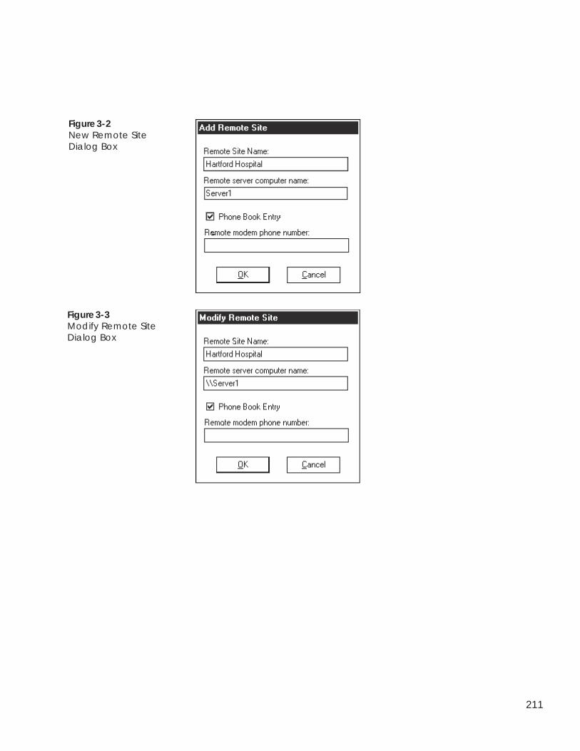
211
Figure 3-2New Remote SiteDialog Box
Figure 3-3Modify Remote SiteDialog Box
212
1. Double click on the ComfortVIEW Remote Site Managericon to launch the application.
Note: It is not necessary to log in to ComfortVIEWbefore running this application.
ComfortVIEW launches the Remote Site Manager applicationand displays the ComfortVIEW Remote Site Manager dialogbox. Refer to Figure 3-1.
2. In the ComfortVIEW Remote Sites list, click on the remotesite that you wish to delete and then click on Delete.
Deleting aSite from the
ComfortVIEW RemoteSite List

WorkSPACEManager

Alarm Manager
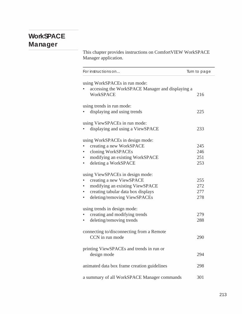
213
WorkSPACEManager
This chapter provides instructions on ComfortVIEW WorkSPACEManager application.
For instructions on... Turn to page
using WorkSPACEs in run mode:• accessing the WorkSPACE Manager and displaying a
WorkSPACE 216
using trends in run mode:• displaying and using trends 225
using ViewSPACEs in run mode:• displaying and using a ViewSPACE 233
using WorkSPACEs in design mode:• creating a new WorkSPACE 245• cloning WorkSPACEs 246• modifying an existing WorkSPACE 251• deleting a WorkSPACE 253
using ViewSPACEs in design mode:• creating a new ViewSPACE 255• modifying an existing ViewSPACE 272• creating tabular data box displays 277• deleting/removing ViewSPACEs 278
using trends in design mode:• creating and modifying trends 279• deleting/removing trends 288
connecting to/disconnecting from a RemoteCCN in run mode 290
printing ViewSPACEs and trends in run ordesign mode 294
animated data box frame creation guidelines 298
a summary of all WorkSPACE Manager commands 301
214
The following terms are used throughout this WorkSPACE Managerchapter.
Animated Data Box — A graphic that displays an animated (mov-ing) picture of the discrete point it is representing. For example, afan circulating air or a filter with air passing through it.
Auto — To remove a force and return a point to the controller’sautomatic control.
Bookmark — A tag, which you place on a WorkSPACE whileoperating in run mode, to allow you to quickly jump to and display itusing the File menu’s Open bookmark command. The presence of abookmark icon in the lower right corner of a WorkSPACE windowindicates that the WorkSPACE is currently bookmarked.
Controller — A CCN system element with an address, statusdisplay, and configuration tables. A controller performs the actualHVAC monitoring and control operations. The Carrier ComfortNetwork supports several types of controllers. These include PICs,FIDs, Comfort Controllers, System Managers (examples: TSM,FSM, CSM), and CCN options.
Data Box — A rectangular box, which is superimposed on aViewSPACE’s graphic background, that contains the followinguser-configurable information: configuration, status display, ormaintenance point’s name, 24 character description, value and units,communication or alarm status, and/or force state. Data boxes fordiscrete points can also appear as animated graphics.
Design Mode — The WorkSPACE Manager mode that you enter tocreate or modify ViewSPACEs and trends. While in design modeyou perform operations such as selecting a graphic background,assigning data points to display on the ViewSPACE or trend, andestablishing links to other WorkSPACEs. You enter design mode byclicking on the run mode’s Run menu item and then clicking onEnter design mode (or by pressing the F6 key).
Download — To copy configuration table data from theComfortVIEW database to a controller. Performing a downloadoverwrites all configuration at the controller.
Terminology
215
Force — To override a controller’s automatic control and modifythe point’s value.
Global — A WorkSPACE, ViewSPACE, or trend that can be used,modified, or deleted by any user. You designate whether aWorkSPACE, ViewSPACE, or trend will be “Global” during thesave process.
Link areas — Boxes, which you add to ViewSPACEs, to provide aquick jump to another WorkSPACE. You can create up to 15 linkareas in a ViewSPACE window. Double-clicking on a link areawhile in run mode closes the current ViewSPACE and WorkSPACEand displays the linked WorkSPACE.
Object — A Comfort Controller hardware or software point, systemtable, algorithm, setpoint, alarm, or function.
Owned — A WorkSPACE, ViewSPACE, or trend that can bedisplayed by any user, but can only be modified or deleted by thecreator. You designate whether a WorkSPACE, ViewSPACE, ortrend will be “Owned” during the save process.
Run Mode — The WorkSPACE Manager mode that you enter todisplay ViewSPACEs and trends. While in this mode, ViewSPACEand trend plot values dynamically update. You perform operationssuch as forcing and autoing point values and statuses, modifyingconfiguration table values, and displaying linked WorkSPACEs.You enter run mode by clicking on the design mode’s Run menuitem and then clicking on Start run mode (or by pressing the F5key).
System Element — A CCN controller with an address and configu-ration tables. A controller performs the actual HVAC monitoringand control operations. The Carrier Comfort Network supportsseveral types of system elements. These include PICs, FIDs, Com-fort Controllers, System Managers (examples: TSM, FSM, CSM),and CCN options.
Trend — A window consisting of a dynamic plot of up to sixpoints-worth of data.
Upload — To copy configuration table data from a controller to theComfortVIEW database.
216
Accessing theWorkSPACEManager
ViewSPACE — A window consisting of a graphic background (forexample, a chiller or an air handler graphic) with up to 60 dynamicor animated data boxes, which display point value or status informa-tion, and up to 15 link areas, which provide a quick jump to anotherWorkSPACE. ViewSPACEs may also contain data boxes only,without a graphic background.
WorkSPACE —A collection of up to ten ViewSPACE and up toten trend windows.
The WorkSPACE Manager application gives you the ability tocreate and use customized graphic and trend displays of criticalComfortVIEW data. These graphic and trend displays are referred torespectively as ViewSPACEs and trends. The data that can bedisplayed in a ViewSPACE or trend can be of any type — statusdisplay, maintenance, and configuration, and can include informa-tion from any controller in one, or multiple CCNs.
You create and save ViewSPACEs and trends in collections orgroupings known as WorkSPACEs. A WorkSPACE can contain ofup to ten individual ViewSPACE windows and up to ten individualtrend windows.
You can create a WorkSPACE to simultaneously see all the criticalinformation about your system on a single screen. For example, youcan create a WorkSPACE with a ViewSPACE graphic of your mainchiller and air handler, plus trends plotting key operating data foryour chilled water system. You can then save the WorkSPACE so itis available to access time and again. WorkSPACEs containingtrends and ViewSPACES displaying data from multiple controllersare troubleshooting time-savers, allowing you to adjust the operationof one parameter and see how it affects another part of the system— all on the same screen.
You operate the WorkSPACE Manager in one of two modes: designmode or run mode. Design mode is for creating or modifyingViewSPACEs and trends, while run mode is for displayingViewSPACEs and trends with their data dynamically updating. Youcan, for example, work in the WorkSPACE Manager’s design modeto create a WorkSPACE containing a ViewSPACE window that
Design Mode VersusRun Mode
217
WorkSPACEManager
displays data from your main chiller, a ViewSPACE window thatdisplays data from your main air handler, and a trend window thatsamples space temperatures. You can then switch to theWorkSPACE Manager’s run mode and view the data in theseViewSPACE and trend windows dynamically updating. You canforce and auto display points, and modify configuration pointvalues.
1. Double click on the WorkSPACE Manager icon.
ComfortVIEW displays the Open WorkSPACE dialog boxshown and described in Figure 4-1 and Table 4-1.
Note: If, however, you have identified a defaultWorkSPACE using the Configure menu’s Setdefault WorkSPACE command (in Design mode),the selected default WorkSPACE window opens andits associated ViewSPACEs and trends display inrun mode.
To Open a Different WorkSPACE: Display theOpen WorkSPACE dialog box by clicking on theFile menu item and then clicking on OpenWorkSPACE, or click on the Open WorkSPACEicon in the toolbar.
2. In the Select WorkSPACE list, click on the WorkSPACE thatyou wish to open and then click on OK.
To Launch theWorkSPACE
Manager Applicationand Open an ExistingWorkSPACE
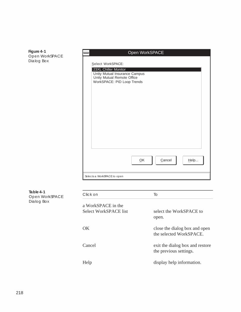
218
Figure 4-1Open WorkSPACEDialog Box
23XL Chiller Monitor
Open WorkSPACE
OK Cancel Help...
Select WorkSPACE:
Unity Mutual Insurance Campus
Selects a WorkSPACE to open
Unity Mutual Remote OfficeWorkSPACE: PID Loop Trends
Click on To
a WorkSPACE in theSelect WorkSPACE list select the WorkSPACE to
open.
OK close the dialog box and openthe selected WorkSPACE.
Cancel exit the dialog box and restorethe previous settings.
Help display help information.
Table 4-1Open WorkSPACEDialog Box
219
General Operation ComfortVIEW opens the selected WorkSPACE window in runmode. The ViewSPACEs and trends that have been assigned to theWorkSPACE open sequentially inside the WorkSPACE window.The messages Loading background screens and Loading datadisplay in the lower left corner of the WorkSPACE window duringthe load process.
For instructions on using ViewSPACEs and trends, refer to theDisplaying and Using a ViewSPACE and Displaying and UsingTrends sections of this chapter.
Figure 4-2 shows a sample WorkSPACE window containing twoViewSPACEs and a trend. The trend's legend is also displayed.
The top line of the WorkSPACE window contains the menu bar.Note that this menu bar changes when you switch between theWorkSPACE Manager’s run and design modes. Refer toWorkSPACE Manager Menu Command Summary at the end of thisWorkSPACE Manager chapter for a description of each run anddesign mode menu item and command.
Menu Bar
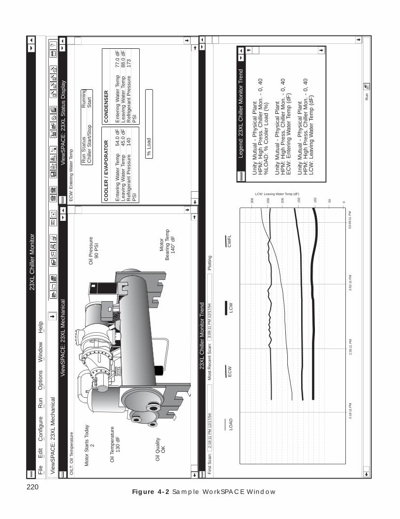
220Figure 4-2 Sample WorkSPACE Window
Lege
nd: 2
3XL
Chi
ller
Mon
itor
Tren
d
Uni
ty M
utua
l - P
hysi
cal P
lant
HP
M:
Hig
h P
ress
. C
hille
r M
on.
- 0,
40
%LO
AD
: %
Coo
ler
Load
(%
)
Uni
ty M
utua
l - P
hysi
cal P
lant
HP
M:
Hig
h P
ress
. C
hille
r M
on.
- 0,
40
EC
W:
Ent
erin
g W
ater
Tem
p (d
F)
Uni
ty M
utua
l - P
hysi
cal P
lant
HP
M:
Hig
h P
ress
. C
hille
r M
on.
- 0,
40
LCW
: Le
avin
g W
ater
Tem
p (d
F)
Vie
wS
PA
CE
: 23X
L S
tatu
s D
ispl
ay
EC
WC
WF
LL
CW
2:18
:11
PM
2:35
:11
PM
2:52
:11
PM
050100
150
200
250
300
LCW: Leaving Water Temp (dF)
Firs
t Sca
n:
23X
L C
hille
r M
onito
r Tr
end
Mos
t Rec
ent S
can:
3:09
:11
PM
12/
17/9
4P
lotti
ng2:
18:1
1 P
M 1
2/17
/94
03:0
9:11
PM
Run
Run
Sta
tus
Run
ning
Chi
ller
Sta
rt/S
top
Sta
rt
EC
W: E
nter
ing
Wat
er T
emp
CO
OL
ER
/ E
VAP
OR
ATO
R
Ent
erin
g W
ater
Tem
p54
.0 d
FL
eavi
ng W
ater
Tem
p45
.0 d
FR
efrig
eran
t P
ress
ure
140
PS
I
CO
ND
EN
SE
R
Ent
erin
g W
ater
Tem
p77
.0 d
FL
eavi
ng W
ater
Tem
p88
.0 d
FR
efrig
eran
t P
ress
ure
173
PS
I
% L
oad
Vie
wS
PA
CE
: 23X
L M
echa
nica
l
Mot
or S
tart
s To
day
2
OIL
T: O
il Te
mpe
ratu
re
Vie
wS
PA
CE
: 23X
L M
echa
nica
l
23X
L C
hille
r M
onito
r
Oil
Tem
pera
ture
130
dF
Oil
Pre
ssur
e90
PS
I
Mot
orB
earin
g Te
mp
140°
dF
Oil
Qua
lity
OK
File
Edi
tC
onfig
ure
Run
Opt
ions
Hel
pW
indo
w
LOA
D
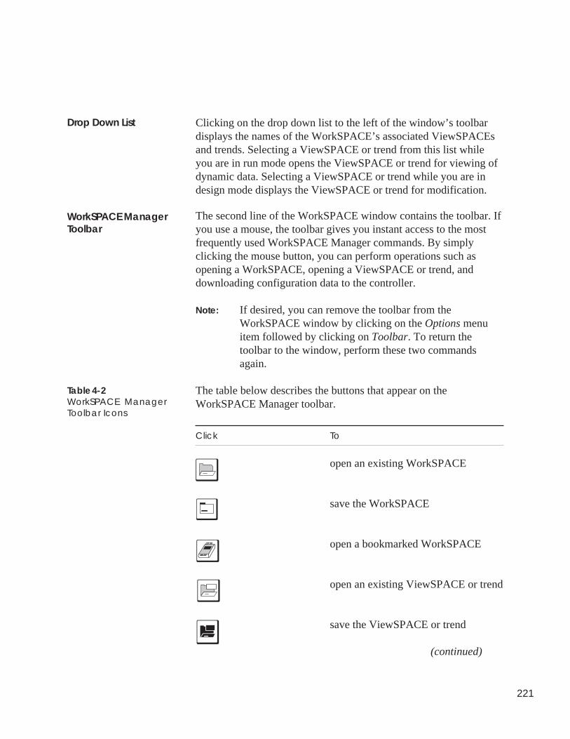
221
Clicking on the drop down list to the left of the window’s toolbardisplays the names of the WorkSPACE’s associated ViewSPACEsand trends. Selecting a ViewSPACE or trend from this list whileyou are in run mode opens the ViewSPACE or trend for viewing ofdynamic data. Selecting a ViewSPACE or trend while you are indesign mode displays the ViewSPACE or trend for modification.
The second line of the WorkSPACE window contains the toolbar. Ifyou use a mouse, the toolbar gives you instant access to the mostfrequently used WorkSPACE Manager commands. By simplyclicking the mouse button, you can perform operations such asopening a WorkSPACE, opening a ViewSPACE or trend, anddownloading configuration data to the controller.
Note: If desired, you can remove the toolbar from theWorkSPACE window by clicking on the Options menuitem followed by clicking on Toolbar. To return thetoolbar to the window, perform these two commandsagain.
The table below describes the buttons that appear on theWorkSPACE Manager toolbar.
Click To
open an existing WorkSPACE
save the WorkSPACE
open a bookmarked WorkSPACE
open an existing ViewSPACE or trend
save the ViewSPACE or trend
(continued)
Drop Down List
WorkSPACE ManagerToolbar
Table 4-2WorkSPACE ManagerToolbar Icons
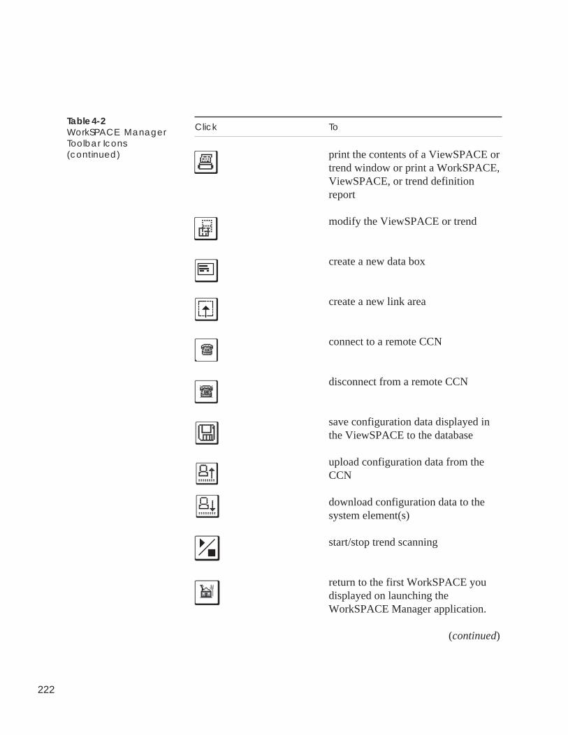
222
Table 4-2WorkSPACE ManagerToolbar Icons(continued)
Click To
print the contents of a ViewSPACE ortrend window or print a WorkSPACE,ViewSPACE, or trend definitionreport
modify the ViewSPACE or trend
create a new data box
create a new link area
connect to a remote CCN
disconnect from a remote CCN
save configuration data displayed inthe ViewSPACE to the database
upload configuration data from theCCN
download configuration data to thesystem element(s)
start/stop trend scanning
return to the first WorkSPACE youdisplayed on launching theWorkSPACE Manager application.
(continued)
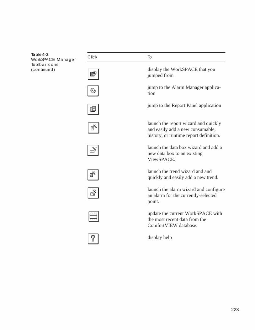
223
Table 4-2WorkSPACE ManagerToolbar Icons(continued)
Click To
display the WorkSPACE that youjumped from
jump to the Alarm Manager applica-tion
jump to the Report Panel application
launch the report wizard and quicklyand easily add a new consumable,history, or runtime report definition.
launch the data box wizard and add anew data box to an existingViewSPACE.
launch the trend wizard and andquickly and easily add a new trend.
launch the alarm wizard and configurean alarm for the currently-selectedpoint.
update the current WorkSPACE withthe most recent data from theComfortVIEW database.
display help
224
Bookmarks give you the capability to tag a WorkSPACE in run modeso that you can quickly jump to it using the File menu’s Open book-mark command.
To Place or Remove a Bookmark
In run mode:
1. Click on the Configure menu item and then click on Set book-mark.
A checkmark (✓ ) appears before the Set bookmark command toindicate that it is enabled.
The presence of the bookmark icon in the lower right corner of aWorkSPACE window also indicates that the WorkSPACE iscurrently bookmarked.
2. To remove a bookmark, perform these two commands again.
To Jump to a Bookmarked WorkSPACE
In run mode:
1. Click on the File menu item and then click on Open bookmark.
Note: You may also perform this command by clicking onthe Open Bookmark icon in the toolbar.
If there is only one bookmarked WorkSPACE in yourComfortVIEW database, the WorkSPACE Manager displays thebookmarked WorkSPACE in run mode.
If there is currently more than one bookmarked WorkSPACE inyour database, the WorkSPACE Manager displays the OpenWorkSPACE dialog box. This dialog box lists the names of allWorkSPACEs that have been bookmarked by you and otherComfortVIEW operators.
2. In the Select WorkSPACE list, click on the WorkSPACE thatyou wish to open and then click on OK.
The WorkSPACE Manager closes the currently-displayedWorkSPACE and opens the selected WorkSPACE.
Bookmarks
225
Displaying andUsing Trends
While displaying a trend in run mode, you can perform the follow-ing functions:
• View the trend dynamically plotting data
• View, modify, upload, download, or save the following trendpoint parameters:• Value• Description• Operator note
• Stop (pause) and start the trend
• Re-start the trend (re-initialize values)
• Jump to and display a point's associated configuration, mainte-nance, time schedule, or setpoint table.
• Display the names of all Comfort Controller objects (hardwareand software points, algorithms, setpoints, alarms, functions, andsystem tables) that are using the selected trend point in theirconfiguration.
• Jump to and display a trend point's table of origin (status dis-play, maintenance, or configuration table).
A trend will run until one of the following conditions is met:
• You stop the trend• 1000 scans have been completed• You remove the trend from the current WorkSPACE• You leave run mode and enter design mode• You close the WorkSPACE (via a linked jump to another
WorkSPACE or by exiting the current WorkSPACE Managerapplication entirely).
Note: You can simultaneously run a trend while viewingother WorkSPACEs by running another instance of theWorkSPACE Manager application. Use the secondWorkSPACE Manager to view other WorkSPACEswhile the first WorkSPACE Manager is running yourtrend.
226
To Launch theWorkSPACE ManagerApplication andDisplay a Trend in RunMode
Note: If the WorkSPACE Manager application is already run-ning, you can display a trend at any time by:
• if necessary, entering run mode (by clicking on theRun menu item and then clicking on Start run mode).
• opening the trend (by clicking on the File menu itemand then clicking on Open ViewSPACE/Trend).
• proceeding to Step 2 in the following list.
1. Launch the WorkSPACE Manager application and select theWorkSPACE containing the trend you wish to display. Ifnecessary, refer to Accessing the WorkSPACE Manager.
ComfortVIEW opens the selected WorkSPACE window. TheViewSPACEs and trends that have been assigned to theWorkSPACE open sequentially inside the WorkSPACEwindow. The messages Loading background screens andLoading data display in the lower left corner of theWorkSPACE window during the load process.
Trends display in run mode and, if the auto start option wasenabled, will begin plotting data when opened. The presenceof the message Plotting in the top right corner of the trendwindow indicates that the trend is sampling data.
Note: If the trend you wish to display is not currentlydisplayed on the screen, click on the drop down listto the left of the window’s toolbar to display thename of each of the WorkSPACE’s associatedViewSPACEs and trends. Then, click on the trendthat you wish to display.
If the trend you wish to display is in anotherWorkSPACE, you can display a list of allViewSPACEs and trends by clicking on the Filemenu item and then clicking on Open ViewSPACE/Trend. The Open ViewSPACE/Trend dialog box isdisplayed. Select the trend that you wish to displayand then click on OK.
227
2. If any trend contains points from a remote CCN, and the trendhas not been configured to automatically establish remoteconnection on display (refer to Figure and Table 4-16), youmust connect to the remote CCN in order to sample the remotepoint data. To connect to a remote CCN, click on Connecttoolbar icon shown at left.
3. If necessary, start the trend by clicking on the Run menu itemand then click on Start trend.
Note: You may also perform this command by clicking onthe Start/Stop Trend icon in the toolbar.
The sample trend shown in Figure 4-3 is plotting the value orstatus of the following points: %LOAD, ECW, LCW, CWFL.The trend started at 2:18:11 pm. The X-axis (horizontal axis)displays the time, and the Y-axis (vertical axis) displays thepoint value range. The currently-displayed Y-axis displays therange for the %LOAD point. The legend, which is displayed tothe right of the trend plot, displays the area name, controllername and description, and point name and description for eachtrend point.
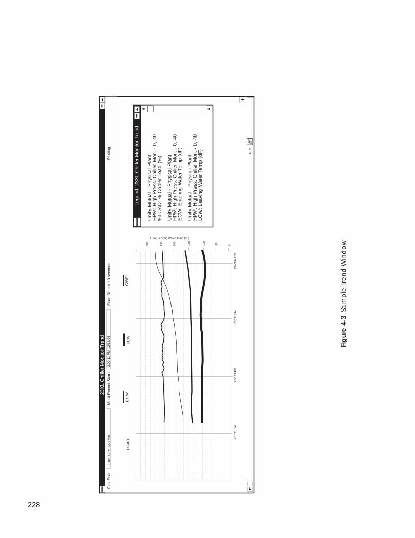
228
Lege
nd: 2
3XL
Chi
ller
Mon
itor
Tren
d
Uni
ty M
utua
l - P
hysi
cal P
lant
HP
M:
Hig
h P
ress
. C
hille
r M
on.
- 0,
40
%LO
AD
: %
Coo
ler
Load
(%
)
Uni
ty M
utua
l - P
hysi
cal P
lant
HP
M:
Hig
h P
ress
. C
hille
r M
on.
- 0,
40
EC
W:
Ent
erin
g W
ater
Tem
p (d
F)
Uni
ty M
utua
l - P
hysi
cal P
lant
HP
M:
Hig
h P
ress
. C
hille
r M
on.
- 0,
40
LCW
: Le
avin
g W
ater
Tem
p (d
F)
EC
WC
WF
LL
CW
2:18
:11
PM
2:35
:11
PM
2:52
:11
PM
050100
150
200
250
300
LCW: Leaving Water Temp (dF)
Firs
t Sca
n:
23X
L C
hille
r M
onito
r Tr
end
Mos
t Rec
ent S
can:
3:09
:11
PM
12/
17/9
4P
lotti
ng2:
18:1
1 P
M 1
2/17
/94
03:0
9:11
PM
Run
LOA
D
Sca
n R
ate
= 1
0 se
cond
s
Fig
ure
4-3
Sa
mp
le T
ren
d W
ind
ow
229
Status Bar The second line of the trend window contains the status bar. Thisstatus bar displays the time the displayed trend started (First Scan),the most recent scan time, and the trend status (Not Active or Plot-ting).
Note: If desired, you can remove the status bar from the windowby clicking on the Options menu item followed by clickingon Status bar. To return the status bar to the window,perform these two commands again.
Trend point names display above the trend.
To activate the Y-axis to display a point’s range, click on thepoint name as it is displayed above the trend.
The minimum and maximum values that are displayed in the plot’s Y-axis change to display the selected point’s range.
1. Display the range for the point in question in the Y-axis. Seeabove.
2. Point to a location on the trend line and hold down the leftmouse button.
The point value will be displayed along with its corresponding trendsample time and date.
1. Click on the Run menu item and then click on Stop Trend.
Note: You may also perform this command by clicking onthe Start/Stop Trend icon in the toolbar.
The message Paused displays in the window’s status bar toshow that the trend is stopped.
To Display a Point’sRange in the Y-Axis
To Display a TrendValue at a SelectedTime
To Stop (Pause) a Trend
230
To Start or Re-start aTrend
You can start or re-start a trend at any time. Starting a trend causes itto resume trending data from the point it was at when you stoppedit. Re-starting a trend clears out (initializes) all previous trend dataand starts the trend again.
Once you’ve started a trend, the trend keeps running until one of thefollowing conditions is met:
• You stop the trend by clicking on the Run menu item and thenclicking on Stop Trend
• You close the WorkSPACE (by double-clicking on aViewSPACE’s link area, by opening a new WorkSPACE, or byexiting the WorkSPACE Manager application entirely)
• 1000 scans have been completed
• You remove the trend from the current WorkSPACE
• You leave run mode and enter design mode
To Start a Trend:
Click on the Run menu item and then click on Start Trend.
The message Plotting displays in the window’s status bar to showthat the trend has been started.
To Re-start a Trend:
Click on the Run menu item and then click on Re-Start Trend.
The message Plotting displays in the window’s status bar to showthat the trend has been started.
231
To View or ModifyTrend Data PointParameters andTrend History
Follow the instructions below to modify a trend point’s value, description,or operator note, or to view the last 50 trend data samples for the point.For configuration points, you can upload configuration data from thecontroller, download data to the controller, and save configuration datachanges in the ComfortVIEW database. For point status or maintenancetable points, you can force and auto point values and save changes.
You can also use ComfortVIEW table jump feature to display andmodify a trend point's associated configuration, maintenance, timeschedule, or setpoint table. In addition, you can display the names ofall Comfort Controller objects that are using a selected trend point intheir configuration. For other CCN system element points, you candisplay the point's table of origin (status display, maintenance, orconfiguration table).
1. Double click on the point name corresponding to the pointwhose parameters or history you wish to view. These pointnames are displayed above the plot.
The WorkSPACE Manager displays the Point Data dialogbox. This box displays the point’s value, description, operatornote, and trend history.
If there is an alarm or force condition currently in effect, analarm or force status indication message is displayed in thelower half of the dialog box.
2. Make point description, value, or operator note changes asdesired. Refer to Figure 4-6 and Table 4-6, which appear laterin this WorkSPACE Manager chapter, for an explanation ofthe fields in the Point Data dialog box.
3. To view the last 50 trend data samples, click on the Historydrop down list box. If you wish to view all trend datasamples, you can do so by saving your trend data to a file.Refer to To Save Trend Data to a File.
4. To display a point's associated configuration, maintenance,time schedule, or setpoint table, click on Configuration table,Maintenance table, Time schedule, or Setpoint table.
5. Clicking on Reference table(s) with a Comfort Controllerpoint selected will display a list of all Comfort Controllerobjects that are using the trend point in their configuration.Clicking on Table of Origin with a point from any CCNsystem element selected will display the point's table of origin(status display, maintenance, or configuration table).
6. Click on Close to exit the dialog box and save any modifications.
232
There are two ways to permanently save your trend data samples:
• In run mode, use the File menu's Save trend data to file com-mand. This command takes a snapshot of the current data andwrites the data to a file name that you specify in the File SaveAs dialog box. This tab-separated file will contain all data that'sbeen gathered since the trend was started for your currentWorkSPACE session. You can then examine this trend data fileat a later time, by reading it into a third party spreadsheet, wordprocessor, or the Windows Notepad application.
• In design mode, select the Edit menu's Modify ViewSPACE/Trend command to display the Modify Current Trend dialog box(refer to Figure and Table 4-18). In that dialog box, specify anarchive file directory path and file name. When the trend isactivated in run mode, the data will be written to this file as it isplotted. You can then re-display the archived trend data in aninactive WorkSPACE Manager trend window using the Filemenu's Open Archived Trend command. This command isavailable in run mode.
Be aware that these are the only methods in which to permanentlysave trend data. Trend data is lost under the following conditions:
• You remove the trend from the current WorkSPACE
• You leave run mode and enter design mode
• You exit the WorkSPACE (by double-clicking on aViewSPACE’s link area, by opening a new WorkSPACE, or byexiting the WorkSPACE Manager application entirely).
To Save Trend Data to aFile
233
Displaying andUsing aViewSPACE
While displaying a ViewSPACE in run mode, you can perform thefollowing functions:
• Connect to a remote CCN to view dynamic remote values. Toconnect to a remote CCN, click on the Connect toolbar icon.
• View, modify, upload, download, and save the following datapoint parameters:
• Value• Description• Operator note
• Jump to and display a linked WorkSPACE.
• Jump to and display a point's associated configuration, mainte-nance, time schedule, or setpoint table.
• Display the names of all Comfort Controller objects that areusing a selected Comfort Controller point in their configuration.
• Jump to and display a point's table of origin (status display,maintenance, or configuration table).
• Use the trend wizard to quickly and easily create a new trend.
• Use the report wizard to quickly and easily add a new consum-able, runtime, or history report definition.
• Use the alarm wizard to quickly and easily configure an alarmfor the currently-selected point.
• Use the data box wizard to quickly and easily add a new databox to the ViewSPACE.
Note: If the WorkSPACE Manager application is already run-ning, you can display a ViewSPACE at any time by:
• if necessary, entering run mode (by clicking on theRun menu item and then clicking on Start run mode)
• opening the ViewSPACE (by clicking on the Filemenu item and then clicking on Open ViewSPACE/Trend or by clicking on the Open ViewSPACE/Trendicon in the toolbar.)
Launch the WorkSPACE Manager application and, in theOpen WorkSPACE dialog box, select the WorkSPACEcontaining the ViewSPACE you wish to display. If necessary,refer to the Accessing the WorkSPACE Manager section ofthis chapter.
To Launch theWorkSPACE ManagerApplication andDisplay a ViewSPACEin Run Mode
234
The ViewSPACEs and trends that have been assigned to theWorkSPACE open sequentially inside the WorkSPACEwindow. The messages Loading background screens andLoading data display in the lower left corner of theWorkSPACE window during the load process.
Note: If the ViewSPACE you wish to display is not cur-rently displayed on the screen:
Click on the drop down list to the left of thewindow’s toolbar to display the name of each of theWorkSPACE’s associated ViewSPACEs and trends.Then, click on the ViewSPACE that you wish todisplay.
If the ViewSPACE you wish to display is in anotherWorkSPACE:
You can display a list of all ViewSPACEs byclicking on the File menu item and then clicking onOpen ViewSPACE/Trend.
You may also perform this command by clicking onthe Open ViewSPACE/Trend icon in the toolbar.
The Open ViewSPACE/Trend dialog box is dis-played. Select the ViewSPACE that you wish todisplay and then click on OK.
General Operation: ViewSPACEs display in run mode. Databoxes displaying status display table values dynamicallydisplay the controller’s latest values and statuses. Data boxesdisplaying configuration table values display configurationdata as it is stored in the ComfortVIEW database. If desired,you can click on the Configure menu item and then click onUpload ViewSPACE data to display configuration values thatare stored in the controller.
The sample ViewSPACE shown in Figure 4-4 displays a23XL Chiller graphic with five data boxes.
If any ViewSPACE contains points from a remote CCN, andthe ViewSPACE has not been configured to automaticallyestablish remote connection on display (refer to Figure andTable 4-16), you must connect to the remote CCN in order toview the remote point data. To connect to a remote CCN,click on the Connect toolbar icon shown at left.
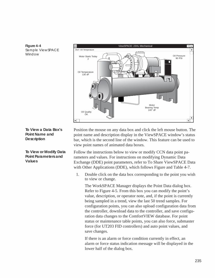
235
Figure 4-4Sample ViewSPACEWindow
ViewSPACE: 23XL Mechanical
Motor Starts Today2
OILT: Oil Temperature
Oil Temperature130 dF
Oil Pressure90 PSI
MotorBearing Temp
140° dFOil Quality
OK
Position the mouse on any data box and click the left mouse button. Thepoint name and description display in the ViewSPACE window’s statusbar, which is the second line of the window. This feature can be used toview point names of animated data boxes.
Follow the instructions below to view or modify CCN data point pa-rameters and values. For instructions on modifying Dynamic DataExchange (DDE) point parameters, refer to To Share ViewSPACE Datawith Other Applications (DDE), which follows Figure and Table 4-7.
1. Double click on the data box corresponding to the point you wishto view or change.
The WorkSPACE Manager displays the Point Data dialog box.Refer to Figure 4-5. From this box you can modify the point’svalue, description, or operator note, and, if the point is currentlybeing sampled in a trend, view the last 50 trend samples. Forconfiguration points, you can also upload configuration data fromthe controller, download data to the controller, and save configu-ration data changes to the ComfortVIEW database. For pointstatus or maintenance table points, you can also force, submasterforce (for UT203 FID controllers) and auto point values, andsave changes.
If there is an alarm or force condition currently in effect, analarm or force status indication message will be displayed in thelower half of the dialog box.
To View a Data Box’sPoint Name andDescription
To View or Modify DataPoint Parameters andValues
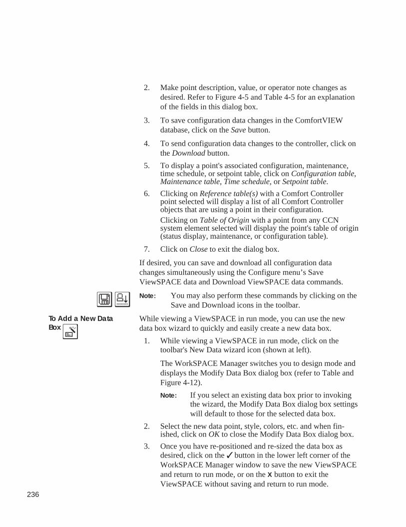
236
2. Make point description, value, or operator note changes asdesired. Refer to Figure 4-5 and Table 4-5 for an explanationof the fields in this dialog box.
3. To save configuration data changes in the ComfortVIEWdatabase, click on the Save button.
4. To send configuration data changes to the controller, click onthe Download button.
5. To display a point's associated configuration, maintenance,time schedule, or setpoint table, click on Configuration table,Maintenance table, Time schedule, or Setpoint table.
6. Clicking on Reference table(s) with a Comfort Controllerpoint selected will display a list of all Comfort Controllerobjects that are using a point in their configuration.Clicking on Table of Origin with a point from any CCNsystem element selected will display the point's table of origin(status display, maintenance, or configuration table).
7. Click on Close to exit the dialog box.
If desired, you can save and download all configuration datachanges simultaneously using the Configure menu’s SaveViewSPACE data and Download ViewSPACE data commands.
Note: You may also perform these commands by clicking on theSave and Download icons in the toolbar.
While viewing a ViewSPACE in run mode, you can use the newdata box wizard to quickly and easily create a new data box.
1. While viewing a ViewSPACE in run mode, click on thetoolbar's New Data wizard icon (shown at left).
The WorkSPACE Manager switches you to design mode anddisplays the Modify Data Box dialog box (refer to Table andFigure 4-12).
Note: If you select an existing data box prior to invokingthe wizard, the Modify Data Box dialog box settingswill default to those for the selected data box.
2. Select the new data point, style, colors, etc. and when fin-ished, click on OK to close the Modify Data Box dialog box.
3. Once you have re-positioned and re-sized the data box asdesired, click on the ✓ button in the lower left corner of theWorkSPACE Manager window to save the new ViewSPACEand return to run mode, or on the X button to exit theViewSPACE without saving and return to run mode.
To Add a New DataBox
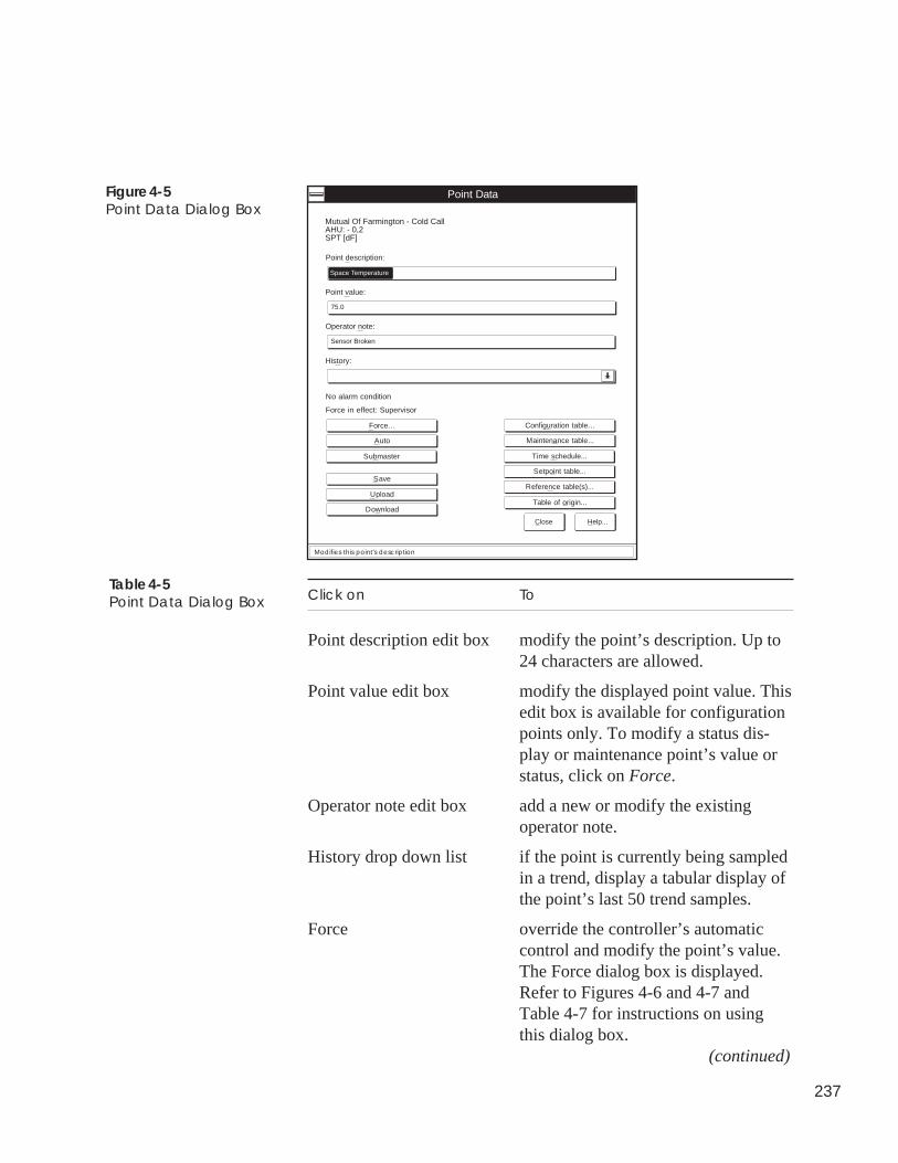
237
Point Data
No alarm condition
Force in effect: Supervisor
Modifies this point's description
Point description:
Point value:
Operator note:
History:
Space Temperature
75.0
Sensor Broken
Mutual Of Farmington - Cold CallAHU: - 0,2SPT [dF]
Close Help...
Configuration table...
Maintenance table...
Time schedule...
Setpoint table...
Reference table(s)...
Table of origin...Download
Save
Upload
Force...
Auto
Submaster
Figure 4-5Point Data Dialog Box
Click on To
Point description edit box modify the point’s description. Up to24 characters are allowed.
Point value edit box modify the displayed point value. Thisedit box is available for configurationpoints only. To modify a status dis-play or maintenance point’s value orstatus, click on Force.
Operator note edit box add a new or modify the existingoperator note.
History drop down list if the point is currently being sampledin a trend, display a tabular display ofthe point’s last 50 trend samples.
Force override the controller’s automaticcontrol and modify the point’s value.The Force dialog box is displayed.Refer to Figures 4-6 and 4-7 andTable 4-7 for instructions on usingthis dialog box.
(continued)
Table 4-5Point Data Dialog Box
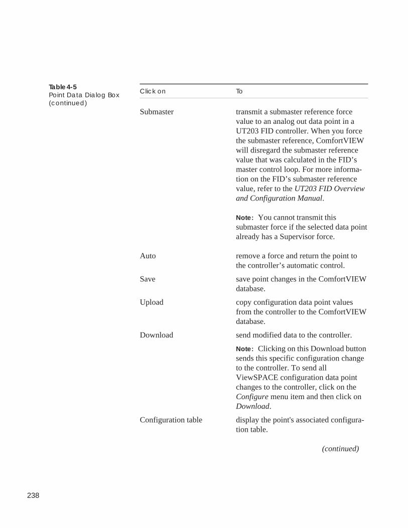
238
Click on To
Submaster transmit a submaster reference forcevalue to an analog out data point in aUT203 FID controller. When you forcethe submaster reference, ComfortVIEWwill disregard the submaster referencevalue that was calculated in the FID’smaster control loop. For more informa-tion on the FID’s submaster referencevalue, refer to the UT203 FID Overviewand Configuration Manual.
Note: You cannot transmit thissubmaster force if the selected data pointalready has a Supervisor force.
Auto remove a force and return the point tothe controller’s automatic control.
Save save point changes in the ComfortVIEWdatabase.
Upload copy configuration data point valuesfrom the controller to the ComfortVIEWdatabase.
Download send modified data to the controller.
Note: Clicking on this Download buttonsends this specific configuration changeto the controller. To send allViewSPACE configuration data pointchanges to the controller, click on theConfigure menu item and then click onDownload.
Configuration table display the point's associated configura-tion table.
(continued)
Table 4-5Point Data Dialog Box(continued)
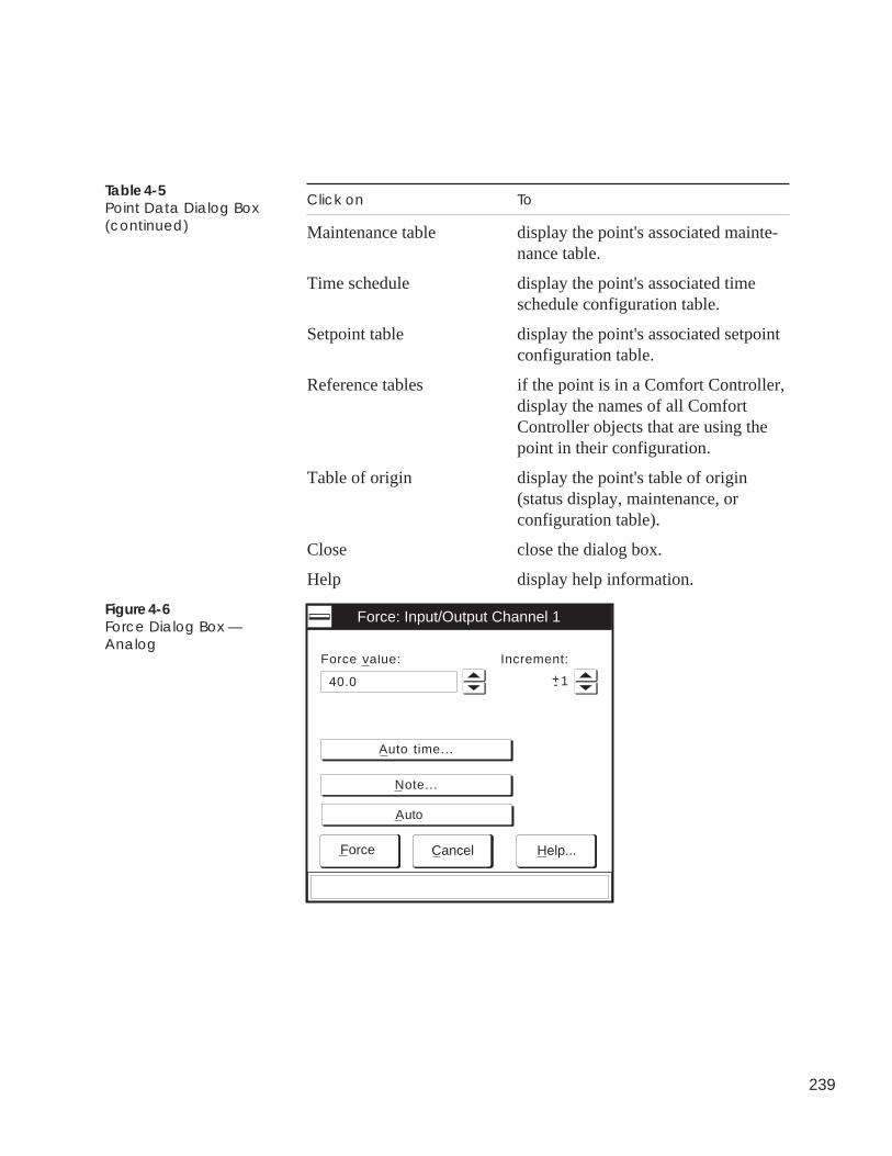
239
Table 4-5Point Data Dialog Box(continued)
Click on To
Maintenance table display the point's associated mainte-nance table.
Time schedule display the point's associated timeschedule configuration table.
Setpoint table display the point's associated setpointconfiguration table.
Reference tables if the point is in a Comfort Controller,display the names of all ComfortController objects that are using thepoint in their configuration.
Table of origin display the point's table of origin(status display, maintenance, orconfiguration table).
Close close the dialog box.
Help display help information.
Force value:
Force: Input/Output Channel 1
Increment:
1+-40.0
Auto time...
Note...
Force Cancel Help...
Auto
Figure 4-6Force Dialog Box —Analog
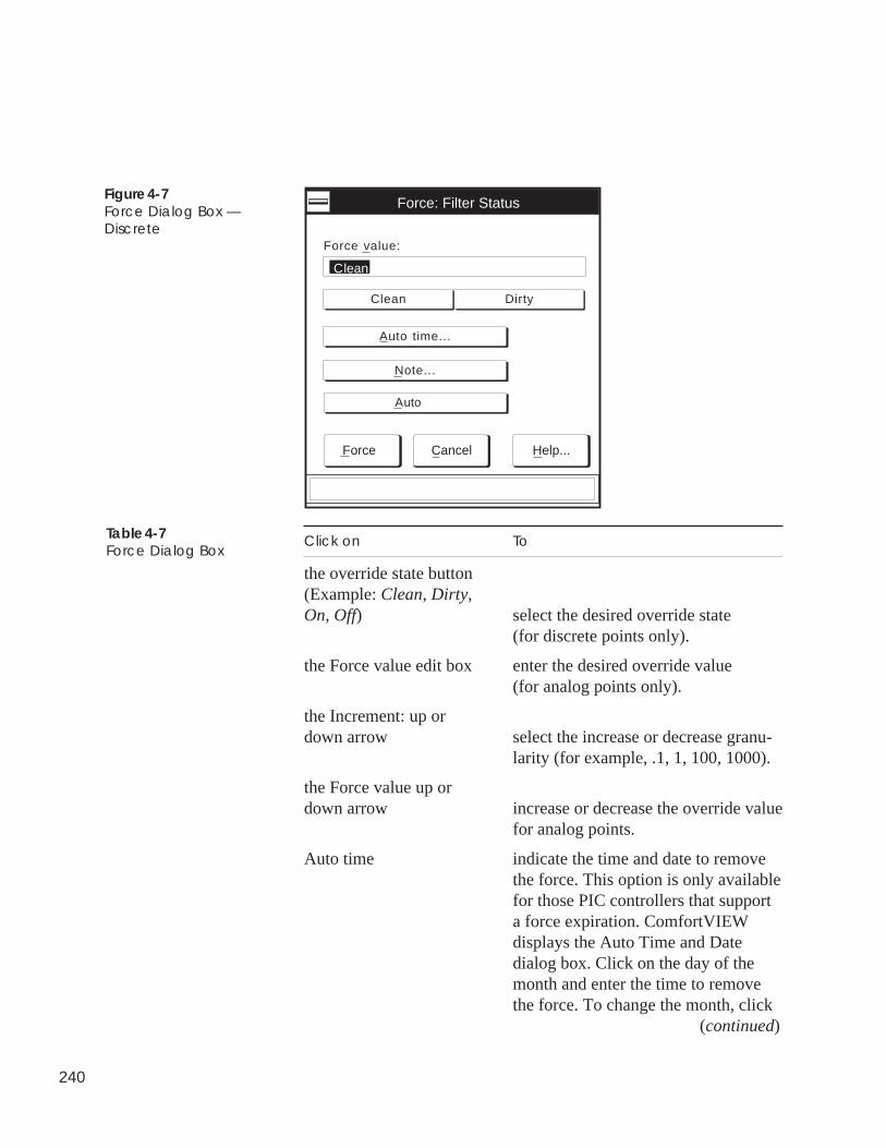
240
Figure 4-7Force Dialog Box —Discrete
Clean Dirty
Force value:
Clean
Force Cancel Help...
Auto time...
Force: Filter Status
Note...
Auto
Click on To
the override state button(Example: Clean, Dirty,On, Off) select the desired override state
(for discrete points only).
the Force value edit box enter the desired override value(for analog points only).
the Increment: up ordown arrow select the increase or decrease granu-
larity (for example, .1, 1, 100, 1000).
the Force value up ordown arrow increase or decrease the override value
for analog points.
Auto time indicate the time and date to removethe force. This option is only availablefor those PIC controllers that supporta force expiration. ComfortVIEWdisplays the Auto Time and Datedialog box. Click on the day of themonth and enter the time to removethe force. To change the month, click (continued)
Table 4-7Force Dialog Box
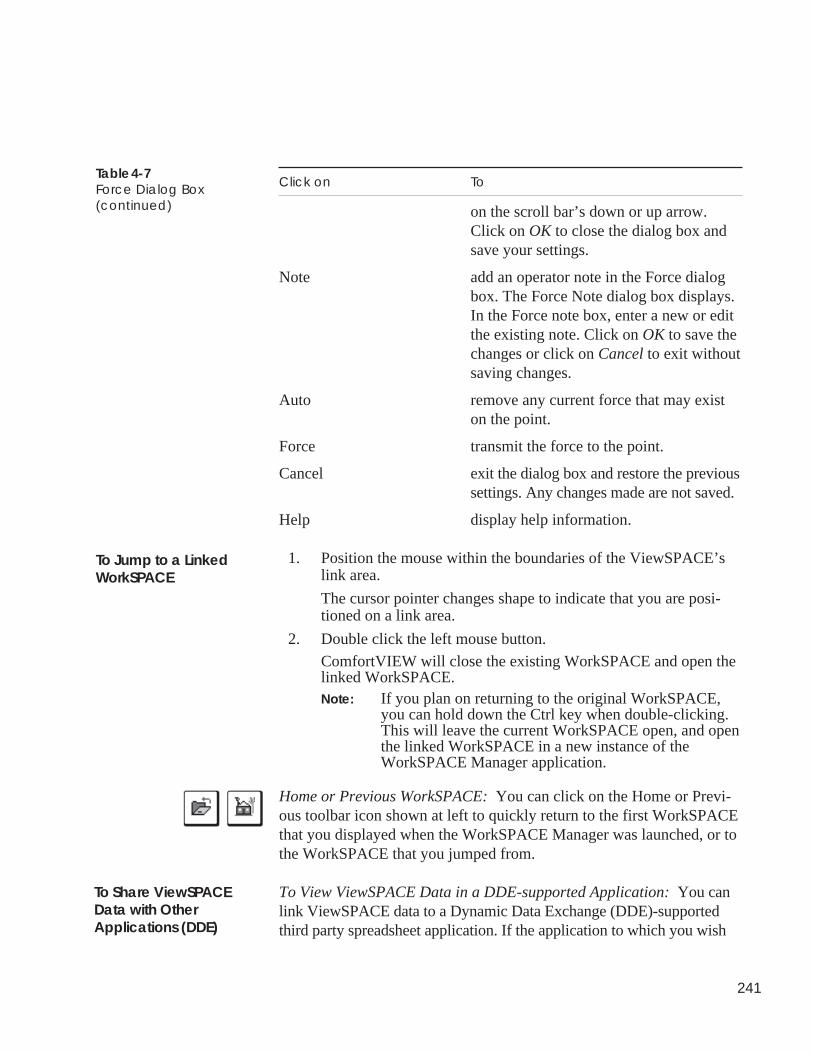
241
Table 4-7Force Dialog Box(continued)
To Jump to a LinkedWorkSPACE
To Share ViewSPACEData with OtherApplications (DDE)
Click on To
on the scroll bar’s down or up arrow.Click on OK to close the dialog box andsave your settings.
Note add an operator note in the Force dialogbox. The Force Note dialog box displays.In the Force note box, enter a new or editthe existing note. Click on OK to save thechanges or click on Cancel to exit withoutsaving changes.
Auto remove any current force that may existon the point.
Force transmit the force to the point.
Cancel exit the dialog box and restore the previoussettings. Any changes made are not saved.
Help display help information.
1. Position the mouse within the boundaries of the ViewSPACE’slink area.
The cursor pointer changes shape to indicate that you are posi-tioned on a link area.
2. Double click the left mouse button.
ComfortVIEW will close the existing WorkSPACE and open thelinked WorkSPACE.Note: If you plan on returning to the original WorkSPACE,
you can hold down the Ctrl key when double-clicking.This will leave the current WorkSPACE open, and openthe linked WorkSPACE in a new instance of theWorkSPACE Manager application.
Home or Previous WorkSPACE: You can click on the Home or Previ-ous toolbar icon shown at left to quickly return to the first WorkSPACEthat you displayed when the WorkSPACE Manager was launched, or tothe WorkSPACE that you jumped from.
To View ViewSPACE Data in a DDE-supported Application: You canlink ViewSPACE data to a Dynamic Data Exchange (DDE)-supportedthird party spreadsheet application. If the application to which you wish
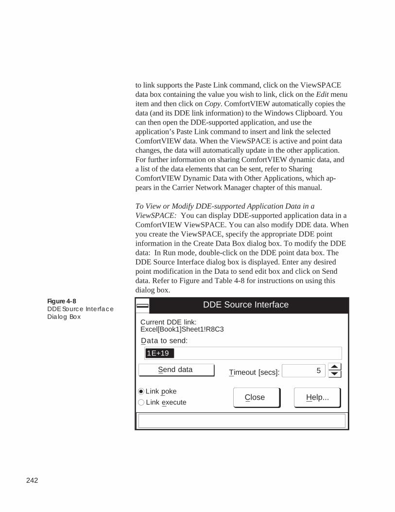
242
to link supports the Paste Link command, click on the ViewSPACEdata box containing the value you wish to link, click on the Edit menuitem and then click on Copy. ComfortVIEW automatically copies thedata (and its DDE link information) to the Windows Clipboard. Youcan then open the DDE-supported application, and use theapplication’s Paste Link command to insert and link the selectedComfortVIEW data. When the ViewSPACE is active and point datachanges, the data will automatically update in the other application.For further information on sharing ComfortVIEW dynamic data, anda list of the data elements that can be sent, refer to SharingComfortVIEW Dynamic Data with Other Applications, which ap-pears in the Carrier Network Manager chapter of this manual.
To View or Modify DDE-supported Application Data in aViewSPACE: You can display DDE-supported application data in aComfortVIEW ViewSPACE. You can also modify DDE data. Whenyou create the ViewSPACE, specify the appropriate DDE pointinformation in the Create Data Box dialog box. To modify the DDEdata: In Run mode, double-click on the DDE point data box. TheDDE Source Interface dialog box is displayed. Enter any desiredpoint modification in the Data to send edit box and click on Senddata. Refer to Figure and Table 4-8 for instructions on using thisdialog box.
Figure 4-8DDE Source InterfaceDialog Box
DDE Source Interface
Data to send:
Link poke
Link execute
Send data 5Timeout [secs]:
Close Help...
Current DDE link:Excel[Book1]Sheet1!R8C3
1E+19
243
Click on To
the Data to send edit box enter the new value to send to theDDE-linked application.
Link poke update the data in the DDE-linkedapplication. For example, if the DDElink represents a cell in an Excelspreadsheet, Link Poke will update thedata in that cell.
Link execute trigger functions in the DDE-linkedapplication. For example, in the DDElink represents a cell in an Excelspreadhsheet, Link Execute could beused to save or close the spreadsheet.
the Timeout edit box indicate the number of seconds thatthe process should wait after initiatinga Poke or Execute before reportingthat no response was received fromthe DDE source.
Send Data send the specified data back to theDDE-linked application.
Close close the dialog box.
Help display help information.
While displaying a ViewSPACE in run mode, you can select a databox and then click on the Alarm Wizard toolbar icon to quickly andeasily configure an alarm for the selected point. Note that wizardoperation will differ, depending on the type of point and CCNsystem element. For Comfort Controllers and UT203 FIDs, thewizard first guides you through point alarm creation and configura-tion, and then ComfortVIEW custom message creation. For all otherCCN system elements, the wizard provides ComfortVIEW customalarm creation only. Follow the steps as presented.
Table 4-8DDE Source InterfaceDialog Box
Alarm Wizard
244
While displaying a ViewSPACE, you can select any data box andthen click on the trend wizard toolbar icon (shown at left) to quicklyand easily set up a trend of that point.
1. In the Trend Wizard dialog box, enter the new trend nameand click on Finish if you are satisfied with the trend's default15 second scan rate, or click on Modify to display the ModifyCurrent Trend dialog box and add other points to the sametrend, or change the default scan rate. Refer to Table andFigure 4-18 for instructions on using this dialog box. Clickingon Finish saves the trend for later use.
Note: To view and run the newly-created trend, use theWorkSPACE Manager's File menu's OpenViewSPACE/trend command. To associate and savethe trend in a WorkSPACE, enter design mode,open a WorkSPACE, open the trend and then savethe WorkSPACE.
While viewing a ViewSPACE in run mode, you can click on anydata box and then on the Report Wizard toolbar icon to quickly andeasily add a new consumable, runtime, or history report definition tothe Report Panel. Follow the steps presented:
1. Select the report type.
2. Specify the report name and description.
3. Select the points to be included in the report. Initially, the listof points presented will include those that were selected fromthe ViewSPACE.
4. Select a specific Data Collection Module in which to allocatethe Data Collection Tables. By default, the wizard locates anavailable module on the current CCN. But you also have theability to identify a specific module, if desired.
5. From the next dialog box, click on Report Options to view ormodify the default settings, if desired.
Trend Wizard
Report Wizard
245
Follow the steps below to launch the WorkSPACE Manager appli-cation and create a new WorkSPACE.
Note: If the WorkSPACE Manager application is already run-ning and is operating in run mode, start with Step 3 below.When in design mode, you can create a new WorkSPACEat any time by clicking on the File menu item and thenclicking on the New WorkSPACE command.
1. Double click on the WorkSPACE Manager icon to launch theWorkSPACE Manager application.
The Open WorkSPACE dialog box is displayed.
2. In the Open WorkSPACE dialog box, click on Cancel.
The dialog box closes and ComfortVIEW displays a newblank WorkSPACE window in run mode.
3. Switch to design mode. To do this, click on the Run menuitem and then click on Enter design mode.
4. Click on No if asked whether you wish to load the currentWorkSPACE for design.
The WorkSPACE Manager enters design mode and displays ablank WorkSPACE. The message Design displays in thelower right corner of the window to indicate that you are indesign mode.
5. You can now create new or add existing ViewSPACEs andtrends to your new WorkSPACE.
To do this, click on the File menu item and then click on oneof the following commands:
• New ViewSPACE/Trend — to create a new ViewSPACEor trend.
For instructions on using this command, refer to theCreating a New ViewSPACE or Creating and ModifyingTrends section of this chapter.
• Open ViewSPACE/Trend — to open an existingViewSPACE or trend window. ComfortVIEW displays
Creating a NewWorkSPACE
246
the Open ViewSPACE/Trend dialog box. Refer to Table4-9 and Figure 4-9.
Note: You may also perform this command by clickingon the Open ViewSPACE/Trend icon in the toolbar.
Select the ViewSPACE or trend that you wish to use andthen click on OK. The WorkSPACE Manager displaysthe selected ViewSPACE or trend on your screen.
6. After adding and saving all of the ViewSPACEs and trends,save the WorkSPACE by clicking on the File menu item andthen clicking on the Save WorkSPACE command.
Note: You may also perform this command by clicking onthe Save WorkSPACE icon in the toolbar.
The Save Current WorkSPACE As dialog box is displayed.Refer to Figure 4-10 and Table 4-10 for instructions on usingthis dialog box.
7. Indicate the WorkSPACE’s ownership designation by click-ing on Owned or Global to enable or disable these options.
8. Click on OK to close the dialog box and save theWorkSPACE, or on Cancel to close the dialog box withoutsaving.
The WorkSPACE Manager saves the WorkSPACE and allassociated ViewSPACEs and trends with their current win-dow locations and sizes. When you display the WorkSPACEin run mode, all ViewSPACEs and trends display with thewindow location and size that they had when theWorkSPACE was saved.
If you have a WorkSPACE containing ViewSPACEs and trendswith points from a single controller, you can use the cloning featureto quickly create another WorkSPACE containing identical pointsfrom another controller of the same type and version. This featurewould be particularly useful when designing WorkSPACEs for azoned system, for example.
WorkSPACE Cloning
247
Follow the instructions below to clone a WorkSPACE:
Note: You can only clone a WorkSPACE if all its points arefrom a single controller.
1. In design mode, open an existing, or create and save a newWorkSPACE.
2. Click on the File menu item and then click on SaveWorkSPACE as.
3. In the Save WorkSPACE As dialog box (refer to Figure 4-10), click on the Clone button.
The Clone WorkSPACE dialog box is displayed. Refer toFigure and Table 4-10a.
4. Enter the name of the new WorkSPACE and click on OK.
The Select Element dialog box will be displayed.
In the Select Element dialog box, select the new systemelement's area and element name and address, and click onOK.
Note: If all of the original ViewSPACE and trend pointsare from a single table, the Select Table dialog boxwill be displayed in place of the Selec Elementdialog box. In this dialog box you can select thearea, element, table category, and table name for thenew WorkSPACE's points. Then, click on OK tosave your selection and close the dialog box.
ComfortVIEW will create a new WorkSPACE and copy allexisting ViewSPACEs and trends along with all associatedpoints to it.
A dialog box, titled with the name of your new WorkSPACEand listing the names of all of the cloned ViewSPACEs andtrends, will now be displayed.
5. Click on Close to close the dialog box.
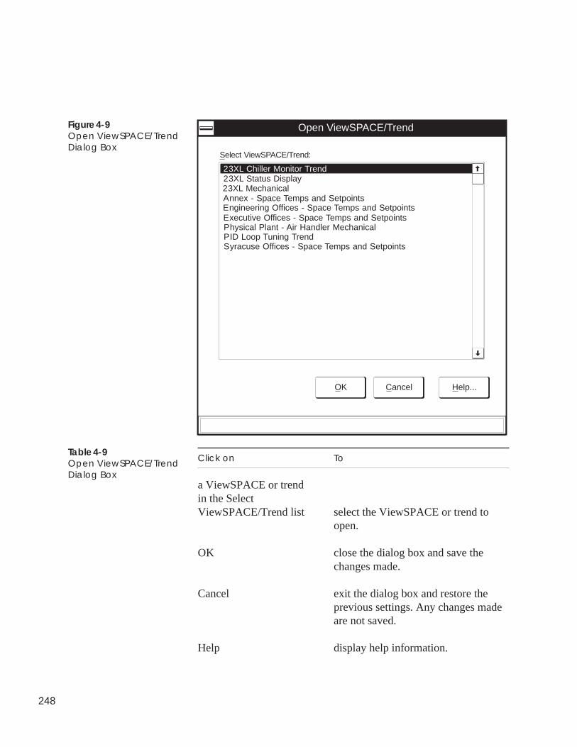
248
23XL Chiller Monitor Trend
Open ViewSPACE/Trend
OK Cancel Help...
Select ViewSPACE/Trend:
23XL Status Display23XL MechanicalAnnex - Space Temps and SetpointsEngineering Offices - Space Temps and SetpointsExecutive Offices - Space Temps and SetpointsPhysical Plant - Air Handler MechanicalPID Loop Tuning TrendSyracuse Offices - Space Temps and Setpoints
Figure 4-9Open ViewSPACE/TrendDialog Box
Click on To
a ViewSPACE or trendin the SelectViewSPACE/Trend list select the ViewSPACE or trend to
open.
OK close the dialog box and save thechanges made.
Cancel exit the dialog box and restore theprevious settings. Any changes madeare not saved.
Help display help information.
Table 4-9Open ViewSPACE/TrendDialog Box
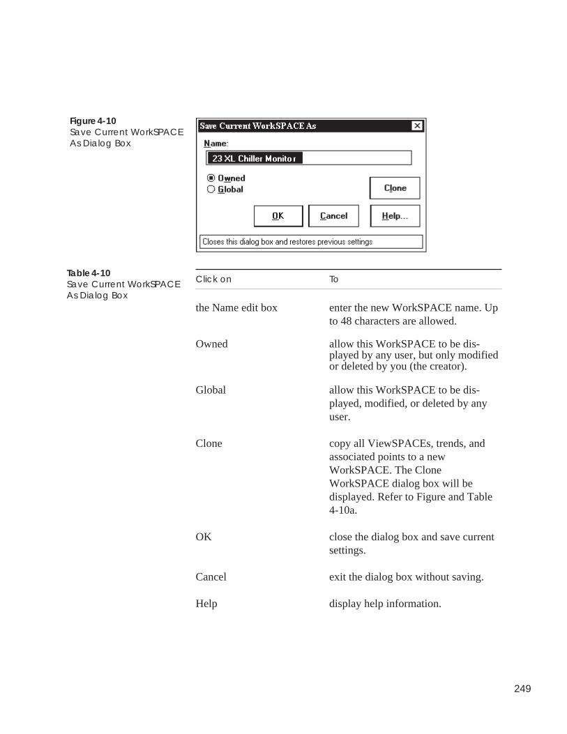
249
Figure 4-10Save Current WorkSPACEAs Dialog Box
Click on To
the Name edit box enter the new WorkSPACE name. Upto 48 characters are allowed.
Owned allow this WorkSPACE to be dis-played by any user, but only modifiedor deleted by you (the creator).
Global allow this WorkSPACE to be dis-played, modified, or deleted by anyuser.
Clone copy all ViewSPACEs, trends, andassociated points to a newWorkSPACE. The CloneWorkSPACE dialog box will bedisplayed. Refer to Figure and Table4-10a.
OK close the dialog box and save currentsettings.
Cancel exit the dialog box without saving.
Help display help information.
Table 4-10Save Current WorkSPACEAs Dialog Box
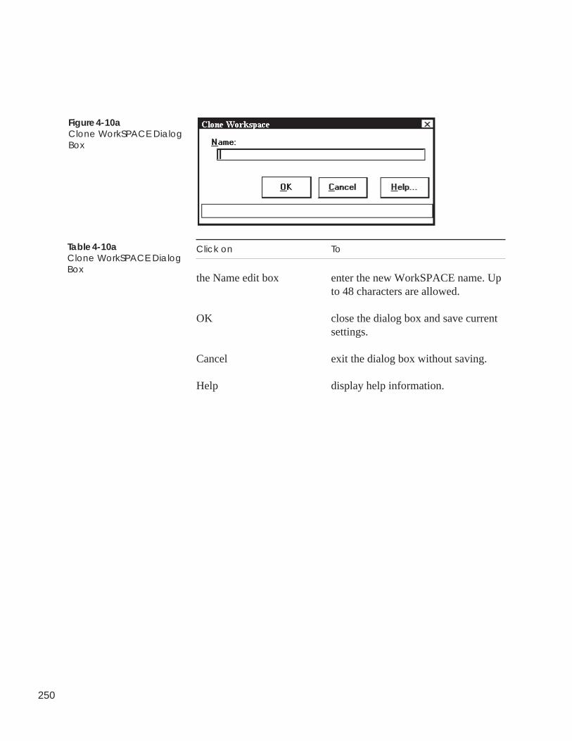
250
Figure 4-10aClone WorkSPACE DialogBox
Table 4-10aClone WorkSPACE DialogBox
Click on To
the Name edit box enter the new WorkSPACE name. Upto 48 characters are allowed.
OK close the dialog box and save currentsettings.
Cancel exit the dialog box without saving.
Help display help information.
251
Modifying anExistingWorkSPACE
Follow the instructions below to launch the WorkSPACE Managerapplication and modify an existing WorkSPACE. You can modify theWorkSPACE name and its owned/global designation. If desired, you canalso modify or delete the WorkSPACE’s existing ViewSPACEs andtrends, or add new ViewSPACEs and trends to the WorkSPACE.
Note: If the WorkSPACE Manager application is already running andin design mode, you can modify an existing WorkSPACE atany time by:
• clicking on the File menu item and then clicking on theOpen WorkSPACE command (or by clicking on the OpenWorkSPACE icon in the toolbar).
• selecting the WorkSPACE that you wish to modify.
• proceeding to Step 6 in the following list.
1. Double click on the WorkSPACE Manager icon to launch theWorkSPACE Manager application.
The Open WorkSPACE dialog box is displayed.
2. In the Open WorkSPACE dialog box, click on Cancel.
The dialog box closes and ComfortVIEW displays a new blankWorkSPACE window in run mode.
3. Switch to design mode. To do this, click on the Run menu itemand then click on Enter design mode.
4. Click on Yes when asked whether you wish to load the currentWorkSPACE for design.
The WorkSPACE Manager enters design mode and displays ablank WorkSPACE. The message Design displays in the lowerright corner of the window to indicate that you are in design mode.
5. Open the WorkSPACE that you wish to modify. To do this, clickon the File menu item and then click on Open WorkSPACE.
Note: You may also perform this command by clicking on theOpen WorkSPACE icon in the toolbar.
6. To modify the WorkSPACE name, click on the Edit menu itemand then click on Modify WorkSPACE.
The Modify Current WorkSPACE dialog box is displayed. Referto Figure 4-11 and Table 4-11.
252
7. Modify the WorkSPACE name as desired, and then click on OK.
The name change will be made permanent when you save theWorkSPACE.
8. You can now modify or delete existing ViewSPACEs and trends,or add new ViewSPACEs and trends to the WorkSPACE.
Instructions on performing these operations can be found in thefollowing sections of this chapter:
• Modifying an Existing ViewSPACE• Displaying and Using Trends• Creating and Modifying Trends• Deleting/Removing ViewSPACEs• Deleting/Removing Trends
9. Save the modified WorkSPACE as follows:
• To save the WorkSPACE and overwrite previous modifica-tions: Click on the File menu item and then click on the SaveWorkSPACE command.
This command will overwrite the existing WorkSPACE.
Note: You may also perform this command by clicking on theSave WorkSPACE icon in the toolbar.
• To save the WorkSPACE with a new name: Click on the Filemenu item and then click on the Save WorkSPACE as com-mand.
This command saves a new version of an existingWorkSPACE. The Save Current WorkSPACE As dialog box isdisplayed. Refer to Figure 4-10 and Table 4-10 for instructionson using this dialog box.
The WorkSPACE Manager saves the WorkSPACE and all associ-ated ViewSPACEs and trends with their current window locationsand sizes. When you display the WorkSPACE in run mode, allViewSPACEs and trends display with the window location and sizethat they had when the WorkSPACE was saved.
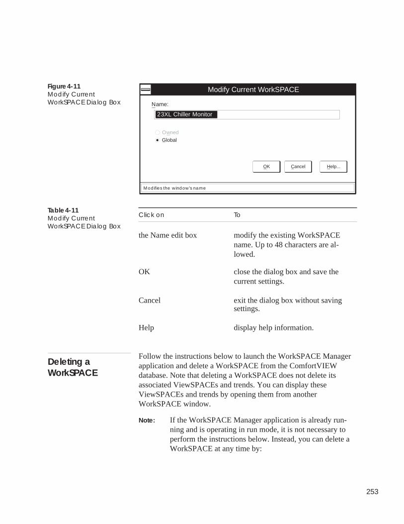
253
Figure 4-11Modify CurrentWorkSPACE Dialog Box
Click on To
the Name edit box modify the existing WorkSPACEname. Up to 48 characters are al-lowed.
OK close the dialog box and save thecurrent settings.
Cancel exit the dialog box without saving
Table 4-11Modify CurrentWorkSPACE Dialog Box
settings.
Help display help information.
Follow the instructions below to launch the WorkSPACE Managerapplication and delete a WorkSPACE from the ComfortVIEWdatabase. Note that deleting a WorkSPACE does not delete itsassociated ViewSPACEs and trends. You can display theseViewSPACEs and trends by opening them from anotherWorkSPACE window.
Note: If the WorkSPACE Manager application is already run-ning and is operating in run mode, it is not necessary toperform the instructions below. Instead, you can delete aWorkSPACE at any time by:
Deleting aWorkSPACE
Owned
Modify Current WorkSPACE
Name:
23XL Chiller Monitor
OK Cancel Help...
Global
Modifies the window's name
254
• entering design mode (by clicking on the Run menuitem and then clicking on Enter design mode).
• clicking on the Edit menu item and then clicking onthe Delete WorkSPACE command.
• proceeding to Step 6 in the following list.
1. Double click on the WorkSPACE Manager icon to launch theWorkSPACE Manager application.
The Open WorkSPACE dialog box is displayed.
2. In the Open WorkSPACE dialog box, click on Cancel.
The dialog box closes and ComfortVIEW displays a newblank WorkSPACE window in run mode.
3. Switch to design mode. To do this, click on the Run menu itemand then click on Enter design mode.
The WorkSPACE Manager displays a dialog box asking if youwish to reload the current WorkSPACE for design.
4. Click on Yes.
The WorkSPACE Manager enters design mode and the mes-sage Design displays in the lower right corner of the window.
5. Click on the Edit menu item and then click on DeleteWorkSPACE.
6. In the confirmation dialog box displayed, click on Yes todelete the WorkSPACE or on No to prevent its deletion.
The WorkSPACE Manager closes any currently-displayedViewSPACE and trend windows, deletes the WorkSPACE from theComfortVIEW database, and displays a new undefined WorkSPACEwindow.
255
To create a new ViewSPACE, you must perform the tasks listedbelow. Step-by-step instructions for completing each task follow.
• Enter design mode.
• Create a new or open an existing WorkSPACE into which youwish to include the new ViewSPACE graphic.
• Create the new ViewSPACE and select the pre-drawn graphicdisplay background. Refer to Graphic Background DrawingSpecifications on the following page.
• Create data boxes and assign the data points on the display.Depending on how you configure them, data boxes can appearas rectangular boxes or as animated graphics. A rectangular databox can contain a configuration, status display, or maintenancepoint’s name, 24 character description, value and units, commu-nication or alarm status, and/or force state. An animated graphicdata box displays an animated picture of a discrete point (forexample, a fan circulating air). A data box can also display datafrom a Dynamic Data Exchange (DDE)-linked application.
• Establish links to other WorkSPACEs. Link boxes give you thecapability to jump to another WorkSPACE by double clickingwithin a ViewSPACE’s link box boundaries.
• Save the new ViewSPACE and/or WorkSPACE in yourComfortVIEW database.
Graphic backgrounds should be created using a third party drawingpackage that supports one of the following file formats:
File Extension Type
.BMP Windows bitmap
.DIB Windows bitmap
.GIF Compuserve
.JPG JPEG
.PCX PC Paintbrush (ZSoft format only)
.TIF TIFF
.TGA Truevision Targa
Creating a NewViewSPACE
Overview of theProcess
Graphic BackgroundDrawing Specifications
256
Recommended graphic dimensions for use with a 1024 x 768 superVGA display are as follows:
• Full Screen ViewSPACE Window Size — 1022 x 648 pixels
Multiple full-screen ViewSPACEs can be in one WorkSPACE.However, only one ViewSPACE will be seen in its entirety at atime.
• Cascaded ViewSPACE Window Size — 791 x 421 pixels
A cascaded ViewSPACE window size permits a ViewSPACE tobe seen in its entirety when ViewSPACE windows are displayedusing the cascaded window option.
• Tiled ViewSPACE Window Size — Dimensions dependent onnumber of ViewSPACEs
A tiled ViewSPACE window size permits all ViewSPACEs tobe seen in their entirety when ViewSPACE windows are dis-played using the tiled window option. The size of tiled windowswill vary dependent on the number of open ViewSPACE win-dows.
Follow the steps below to launch the WorkSPACE Manager appli-cation and create a new ViewSPACE graphic.
Note: If the WorkSPACE Manager application is already run-ning, you can create a new ViewSPACE at any time by:
• if necessary, entering design mode (by clicking on theRun menu item and then clicking on Enter design mode).
• opening an existing WorkSPACE (by clicking on the Filemenu item and then clicking on Open WorkSPACE) oropening a new WorkSPACE (by clicking on the Filemenu item and then clicking on New WorkSPACE).
• proceeding to Step 6 in the following list.
1. Double click on the WorkSPACE Manager icon to launch theWorkSPACE Manager application.
The Open WorkSPACE dialog box is displayed.
2. In the Open WorkSPACE dialog box, click on the Cancelbutton.
The dialog box closes and ComfortVIEW displays a blankWorkSPACE window in run mode.
Step-by-step
Instructions
257
3. Switch to design mode. To do this, click on the Run menu itemand then click on Enter design mode.
The WorkSPACE Manager displays a dialog box asking if youwish to reload the current WorkSPACE for design.
4. Click on Yes.
The WorkSPACE Manager enters design mode and the messageDesign displays in the lower right corner of the window.
5. Open the WorkSPACE into which you wish to add this newViewSPACE by clicking on the File menu item and then clickingon Open WorkSPACE.
You may also perform this command by clicking on the OpenWorkSPACE icon in the toolbar.
Note: If you wish to open a new WorkSPACE for theViewSPACE, click on the File menu item and then clickon New WorkSPACE.
6. Open the new ViewSPACE window by clicking on the File menuitem and then clicking on New ViewSPACE.
A blank ViewSPACE window is displayed.
7. Select the Graphic Background:
a. Click on the Configure menu item and then click on Back-ground.
The File Open dialog box is displayed.
b. Select the graphic background file you wish to display ortype the file name in the File Name box. You can select adifferent drive by making your selection from the Drivesdrop down list. You can also select a file that is resident onanother network computer by clicking on the Network button.The selected graphic background loads and displays in theViewSPACE window. The message Loading backgroundimage displays in the lower left corner of the window duringthe load process.
8. Create the First Data Box:
a. Click on the Configure menu item and then click on NewData Box.
Note: You may also perform this command by clickingon the Create New Data Box icon in the toolbar.
258
The WorkSPACE Manager creates a data box on yourgraphic background screen and displays the Modify DataBox tabbed dialog box. Refer to Figure and Table 4-12.
b. In the Data selection tab, click on CCN point (if the datayou wish to display originates from the CCN), or,click on DDE point if the point is being DDE linked toComfortVIEW from another application. For example,Excel.
c. If, in Step 8b above, you selected DDE point, you mustnow specify the DDE application, topic, and item names.If, however, the application from which you are linkingsupports the Paste link function (and you have copied thecell while in the application), you can click on the Pastelink button and the WorkSPACE Manager will automati-cally fill in this information for you. Then, skip to Step 8fand select the data box style.
If, in Step 8 above, you selected CCN point, you mustnow click on Select point to select the CCN point toassign to the data box.
The Data Point Selection dialog box is displayed.
d. From the Select Area, Select Element, Select Category,Select Table, and Select Point drop down lists, select thearea, controller table category, table, and name of thepoint that you wish to display on this new ViewSPACE.Refer to Figure 4-13 and Table 4-13 for instructions onusing the Data Point Selection dialog box.
e. Click on OK to select the currently-displayed point andclose the dialog box, or
Note: If you press the Ctrl key while you click on OK,you will select the point, and keep the dialog boxopen so that you can make additional pointselections.
or click on Cancel to close the dialog box without savingthe point selection.
The Modify Data Box dialog box is re-displayed.
f. In the Modify Data Box dialog box, select the Databoxstyle tab. Then, specify the desired databox display style— Normal or Animated (Animated is for discrete points
259
only), and the box's background and alarm colors.If you select an animated (moving picture) data boxstyle, you must assign graphics that have been pre-drawnusing a third party drawing package and named accord-ing to the frame creation guidelines listed in thischapter’s Animated Data Box Frame Creation Guidelinessection.
Refer to Table 4-12 for an explanation of the options inthe Modify Data Box tabbed dialog box.
g. Now, in the Modify Data Box tabbed dialog box, selectthe Font and colors tab. Select the font and the dataelements that you wish to display (point name, descrip-tion, etc.) You can also specify an associated displaycolor for each element.
h. Clicking on the Modify Data Box dialog box's Layouttab brings up a sample databox that displays your currentdatabox style and element selections. You can furthercustomize your databox presentation by using the Win-dows drag and drop technique to move data elementsaround in the sample data box.
i. After all Modify Data Box dialog box tabs have beenselected and your sample data box appears as desired,click on OK to close the dialog box and save the data boxsettings, or
click on Cancel to close the dialog box without savingsettings.The ViewSPACE window re-displays with the newlyconfigured data box placed on the graphic backgroundscreen.
j. Drag the data box to re-position it as desired.
If desired, you can also re-size the box by dragging acorner.
9. Create Additional Data Boxes:
260
Once you’ve designed your first data box, you can copy andpaste it to quickly and easily create additional data boxes.Follow the steps below:
a. Click on the data box that you created in Step 8.
b. Click on the Edit menu item and then click on Copy.
c. Click on the Edit menu item again and then click onPaste.
The WorkSPACE Manager copies the selected data boxand pastes the copy on the graphic background screen.The new data box will be placed partially on top of theoriginal.
d. Drag the data box to re-position it as desired.
e. Double click on the data box to display the Modify DataBox dialog box and modify the point selection and otherdialog box options accordingly. Refer to Step 8 of this listand to Table 4-12 for instructions on using the ModifyData Box dialog box.
10. Create your link areas. You can place up to fifteen link areason a ViewSPACE.
a. Click on the Configure menu item and then click on Newlink area.
Note: You may also perform this command by clickingon the New Link Area icon in the toolbar.
The Modify Link Area dialog box is displayed. Refer toFigure 4-15.
b. Select the WorkSPACE to which you wish to link, clickon Border to enable or disable display of a border aroundthe link area, and then click on OK.
The WorkSPACE Manager displays the link area box onyour graphic background screen.
c. You can re-size the link area by dragging the box corner.
d. You can re-position the link area by dragging it.
11. If desired, you can "lock" the ViewSPACE so that its window
261
size and position, and its link areas, databoxes, and backgroundgraphic cannot be inadvertently altered. To do this, click on theOptions menu item and then click on Lock window.
If desired, you can also select the Options menu's Size image towindow command to force the background graphic to re-sizeitself dynamically based on the size of the ViewSPACE. Thisallows you to display large graphics in their entirety inside aViewSPACE and eliminates the need for use of scroll bars.
12. Save the ViewSPACE:
a. Click on the File menu item and then click on SaveViewSPACE/Trend.
Note: You may also perform this command by clicking onthe Save ViewSPACE/Trend icon in the toolbar.
The Save Current ViewSPACE As dialog box is displayed.Refer to Figure and Table 4-16.
b. Enter a ViewSPACE name.
c. Click on Owned to allow this ViewSPACE to be displayedby any user, but only modified or deleted by you (the cre-ator) or,
click on Global to allow this ViewSPACE to be displayed,modified, or deleted by any user.
d. Click on OK to close the dialog and save the ViewSPACE.
The ViewSPACE window re-displays.
13. Save the WorkSPACE:
a. Click on the File menu item and then click on SaveWorkSPACE.
Note: You may also perform this command by clicking onthe Save WorkSPACE icon in the toolbar.
If the WorkSPACE has not been previously saved, the SaveWorkSPACE As dialog box is displayed. Refer to Figure 4-10 and Table 4-10.
If the WorkSPACE has already been saved, the WorkSPACEManager simply saves the WorkSPACE under the currentname and ownership.
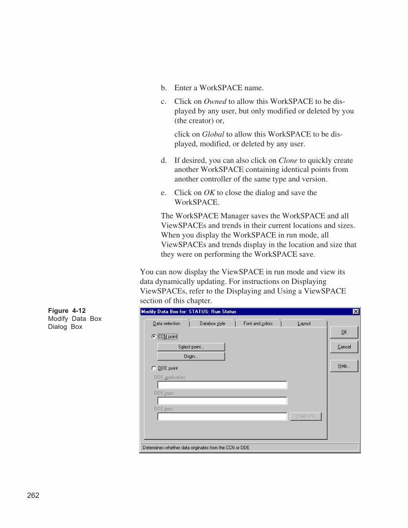
262
b. Enter a WorkSPACE name.
c. Click on Owned to allow this WorkSPACE to be dis-played by any user, but only modified or deleted by you(the creator) or,
click on Global to allow this WorkSPACE to be dis-played, modified, or deleted by any user.
d. If desired, you can also click on Clone to quickly createanother WorkSPACE containing identical points fromanother controller of the same type and version.
e. Click on OK to close the dialog and save theWorkSPACE.
The WorkSPACE Manager saves the WorkSPACE and allViewSPACEs and trends in their current locations and sizes.When you display the WorkSPACE in run mode, allViewSPACEs and trends display in the location and size thatthey were on performing the WorkSPACE save.
You can now display the ViewSPACE in run mode and view itsdata dynamically updating. For instructions on DisplayingViewSPACEs, refer to the Displaying and Using a ViewSPACEsection of this chapter.
Figure 4-12
Modify Data Box
Dialog Box
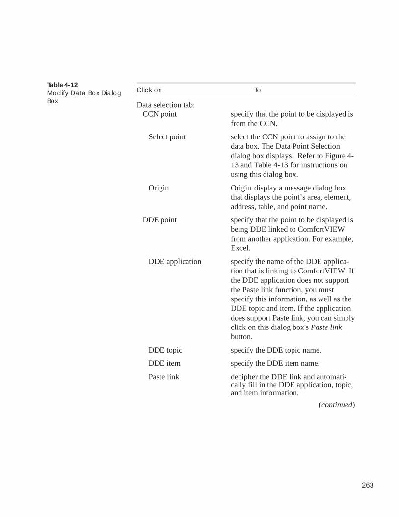
263
Table 4-12Modify Data Box DialogBox
Click on To
Data selection tab:CCN point specify that the point to be displayed is
from the CCN.
Select point select the CCN point to assign to thedata box. The Data Point Selectiondialog box displays. Refer to Figure 4-13 and Table 4-13 for instructions onusing this dialog box.
Origin Origin display a message dialog boxthat displays the point’s area, element,address, table, and point name.
DDE point specify that the point to be displayed isbeing DDE linked to ComfortVIEWfrom another application. For example,Excel.
DDE application specify the name of the DDE applica-tion that is linking to ComfortVIEW. Ifthe DDE application does not supportthe Paste link function, you mustspecify this information, as well as theDDE topic and item. If the applicationdoes support Paste link, you can simplyclick on this dialog box's Paste linkbutton.
DDE topic specify the DDE topic name.
DDE item specify the DDE item name.
Paste link decipher the DDE link and automati-cally fill in the DDE application, topic,and item information.
(continued)
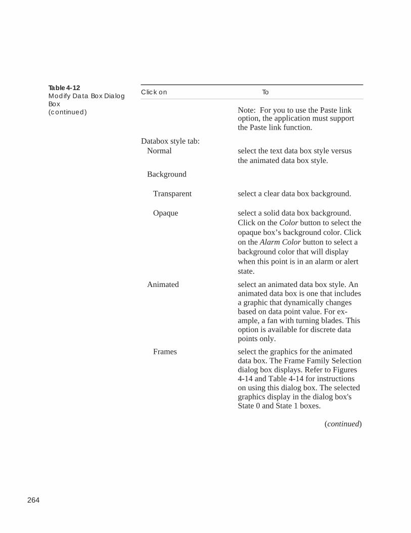
264
Table 4-12Modify Data Box DialogBox(continued)
Click on To
Note: For you to use the Paste linkoption, the application must supportthe Paste link function.
Databox style tab:Normal select the text data box style versus
the animated data box style.
Background
Transparent select a clear data box background.
Opaque select a solid data box background.Click on the Color button to select theopaque box’s background color. Clickon the Alarm Color button to select abackground color that will displaywhen this point is in an alarm or alertstate.
Animated select an animated data box style. Ananimated data box is one that includesa graphic that dynamically changesbased on data point value. For ex-ample, a fan with turning blades. Thisoption is available for discrete datapoints only.
Frames select the graphics for the animateddata box. The Frame Family Selectiondialog box displays. Refer to Figures4-14 and Table 4-14 for instructionson using this dialog box. The selectedgraphics display in the dialog box'sState 0 and State 1 boxes.
(continued)
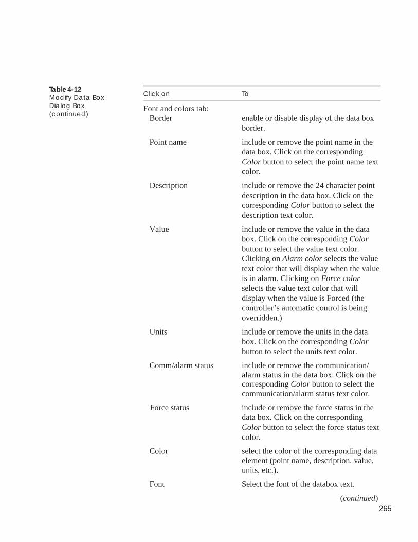
265
Table 4-12Modify Data BoxDialog Box(continued)
Click on To
Font and colors tab:Border enable or disable display of the data box
border.
Point name include or remove the point name in thedata box. Click on the correspondingColor button to select the point name textcolor.
Description include or remove the 24 character pointdescription in the data box. Click on thecorresponding Color button to select thedescription text color.
Value include or remove the value in the databox. Click on the corresponding Colorbutton to select the value text color.Clicking on Alarm color selects the valuetext color that will display when the valueis in alarm. Clicking on Force colorselects the value text color that willdisplay when the value is Forced (thecontroller’s automatic control is beingoverridden.)
Units include or remove the units in the databox. Click on the corresponding Colorbutton to select the units text color.
Comm/alarm status include or remove the communication/alarm status in the data box. Click on thecorresponding Color button to select thecommunication/alarm status text color.
Force status include or remove the force status in thedata box. Click on the correspondingColor button to select the force status textcolor.
Color select the color of the corresponding dataelement (point name, description, value,units, etc.).
Font Select the font of the databox text.
(continued)
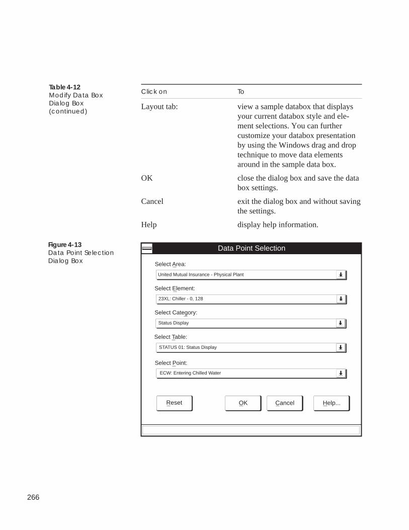
266
Click on To
Layout tab: view a sample databox that displaysyour current databox style and ele-ment selections. You can furthercustomize your databox presentationby using the Windows drag and droptechnique to move data elementsaround in the sample data box.
OK close the dialog box and save the databox settings.
Cancel exit the dialog box and without savingthe settings.
Help display help information.
Table 4-12Modify Data BoxDialog Box(continued)
Figure 4-13Data Point SelectionDialog Box
Data Point Selection
Select Area:
Cancel Help...
Select Element:
Select Category:
Select Table:
Select Point:
United Mutual Insurance - Physical Plant
23XL: Chiller - 0, 128
Status Display
STATUS 01: Status Display
ECW: Entering Chilled Water
OKReset
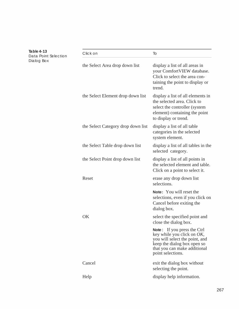
267
Table 4-13Data Point SelectionDialog Box
Click on To
the Select Area drop down list display a list of all areas inyour ComfortVIEW database.Click to select the area con-taining the point to display ortrend.
the Select Element drop down list display a list of all elements inthe selected area. Click toselect the controller (systemelement) containing the pointto display or trend.
the Select Category drop down list display a list of all tablecategories in the selectedsystem element.
the Select Table drop down list display a list of all tables in theselected category.
the Select Point drop down list display a list of all points inthe selected element and table.Click on a point to select it.
Reset erase any drop down listselections.
Note: You will reset theselections, even if you click onCancel before exiting thedialog box.
OK select the specified point andclose the dialog box.
Note: If you press the Ctrlkey while you click on OK,you will select the point, andkeep the dialog box open sothat you can make additionalpoint selections.
Cancel exit the dialog box withoutselecting the point.
Help display help information.

268
Frame Family Selection
Animated frame family:
OK Cancel Help...
FTLRFANS
TEST
On: Off:
Selects animated frames
Figure 4-14Frame Family SelectionDialog Box
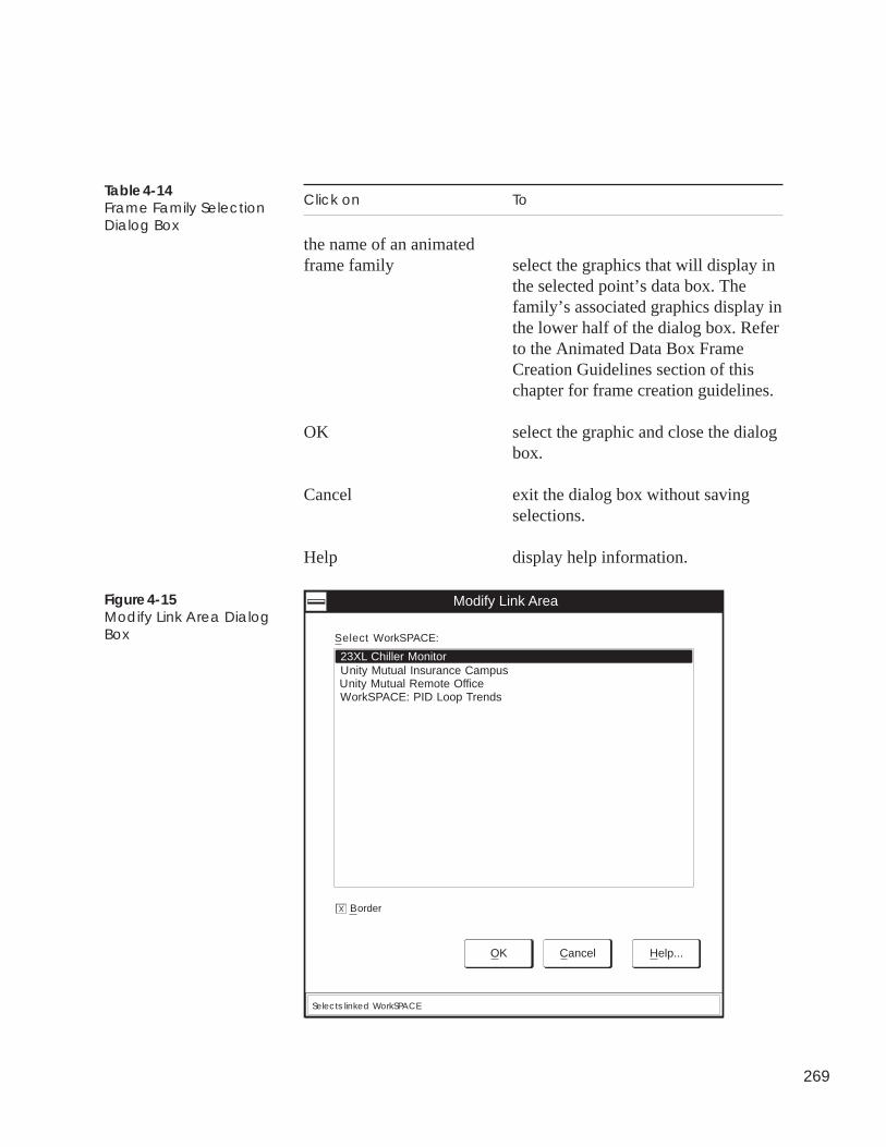
269
Table 4-14Frame Family SelectionDialog Box
Click on To
the name of an animatedframe family select the graphics that will display in
the selected point’s data box. Thefamily’s associated graphics display inthe lower half of the dialog box. Referto the Animated Data Box FrameCreation Guidelines section of thischapter for frame creation guidelines.
OK select the graphic and close the dialogbox.
Cancel exit the dialog box without savingselections.
Help display help information.
Modify Link Area
OK Cancel Help...
Select WorkSPACE:
Selects linked WorkSPACE
BorderX
23XL Chiller MonitorUnity Mutual Insurance CampusUnity Mutual Remote OfficeWorkSPACE: PID Loop Trends
Figure 4-15Modify Link Area DialogBox
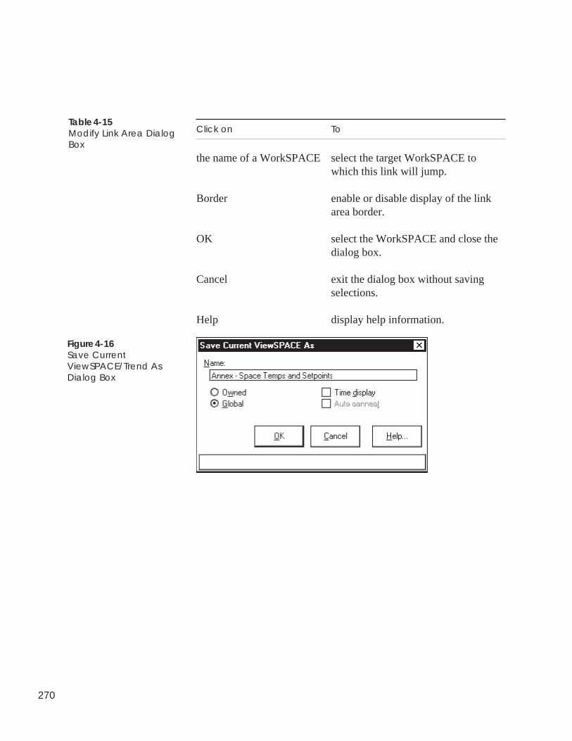
270
Click on To
the name of a WorkSPACE select the target WorkSPACE towhich this link will jump.
Border enable or disable display of the linkarea border.
OK select the WorkSPACE and close thedialog box.
Cancel exit the dialog box without savingselections.
Help display help information.
Table 4-15Modify Link Area DialogBox
Figure 4-16Save CurrentViewSPACE/Trend AsDialog Box
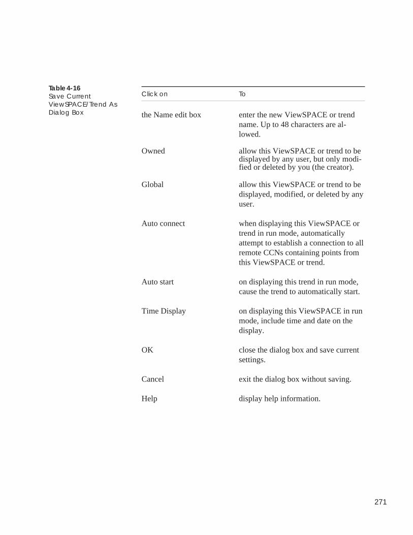
271
Click on To
the Name edit box enter the new ViewSPACE or trendname. Up to 48 characters are al-lowed.
Owned allow this ViewSPACE or trend to bedisplayed by any user, but only modi-fied or deleted by you (the creator).
Global allow this ViewSPACE or trend to bedisplayed, modified, or deleted by anyuser.
Auto connect when displaying this ViewSPACE ortrend in run mode, automaticallyattempt to establish a connection to allremote CCNs containing points fromthis ViewSPACE or trend.
Auto start on displaying this trend in run mode,cause the trend to automatically start.
Time Display on displaying this ViewSPACE in runmode, include time and date on thedisplay.
OK close the dialog box and save currentsettings.
Cancel exit the dialog box without saving.
Help display help information.
Table 4-16Save CurrentViewSPACE/Trend AsDialog Box
272
Modifying AnExistingViewSPACE
Follow the instructions below to modify an existing ViewSPACE.You can modify the ViewSPACE name, and all data box parameters,including data box locations and sizes. You can also add new anddelete existing data boxes and link areas.
1. If necessary, enter design mode by clicking on the Run menuitem and then click on Enter design mode.
The WorkSPACE Manager displays a dialog box asking if youwish to reload the current WorkSPACE for design.
2. Click on Yes.
The WorkSPACE Manager displays the selected WorkSPACEin design mode. The message Design will display in the lowerright corner of the window.
3. Display the ViewSPACE that you wish to modify by clickingon the File menu item and then clicking on Open ViewSPACE/Trend.
Note: You may also perform this command by clicking onthe Open ViewSPACE/Trend icon in the toolbar.
1. Click on the Edit menu item and then click on ModifyViewSPACE/trend, or click on the Modify button in theViewSPACE window.
The WorkSPACE Manager displays the Modify CurrentViewSPACE dialog box. Refer to Figure 4-17 and Table 4-17.
Note: You can also display this dialog box by clicking onthe Modify ViewSPACE/Trend icon in the toolbar,or, by double clicking anywhere within theViewSPACE window. Do not, however, click on adata or link box.
2. In the Name edit box, modify the ViewSPACE name as de-sired.
3. Click on OK to close the dialog box and save modifications, oron Cancel to close the dialog box and restore the previoussettings.
To Modify theViewSPACE Name
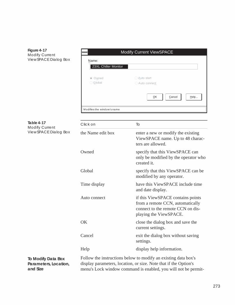
273
Figure 4-17Modify CurrentViewSPACE Dialog Box
Modify Current ViewSPACE
Name:
OK Cancel Help...
Modifies the window's name
23XL Chiller Monitor
Owned
Global
Auto start
Auto connect
Click on To
the Name edit box enter a new or modify the existingViewSPACE name. Up to 48 charac-ters are allowed.
Owned specify that this ViewSPACE canonly be modified by the operator whocreated it.
Global specify that this ViewSPACE can bemodified by any operator.
Time display have this ViewSPACE include timeand date display.
Auto connect if this ViewSPACE contains pointsfrom a remote CCN, automaticallyconnect to the remote CCN on dis-playing the ViewSPACE.
OK close the dialog box and save thecurrent settings.
Cancel exit the dialog box without savingsettings.
Help display help information.
Follow the instructions below to modify an existing data box'sdisplay parameters, location, or size. Note that if the Option'smenu's Lock window command is enabled, you will not be permit-
Table 4-17Modify CurrentViewSPACE Dialog Box
To Modify Data BoxParameters, Location,and Size
274
ted to modify a databox's or link area's location or size. You canselect and modify the display parameters and size of multiple databoxes by holding down the Ctrl key and clicking on each data boxthat you wish to change. Then, follow the instructions below.
To Modify Data Box Parameters
Follow the instructions below to modify the point selection or otherdisplay parameters.
1. Double click on the data box you wish to modify.
Note: If you have selected multiple data boxes, double clickon the first data box you selected. You must continueto press and hold the Ctrl key while double clicking.
The Modify Data Box dialog box is displayed.
Note: You may also display this dialog box by clicking onthe data box, clicking on the Edit menu item, andthen clicking on Modify Object. However, if youhave enabled the Options menu's Lock windowcommand, you will not have access to the ModifyObject command.
2. Modify the data box parameters as desired. Refer to Figure 4-12and Table 4-12 for an explanation of each data box parameter.
3. Click on OK to close the dialog box and save modifications,or on Cancel to close the dialog box and restore the previoussettings.
The data box re-displays with the newly-selected parameters.
To Modify the Data Box Location and Size
1. Click on the data box you wish to modify.
Note: If you have selected multiple data boxes, doubleclick on the first data box you selected. You mustcontinue to press and hold the Ctrl key while doubleclicking.
2. To re-size the box, drag a corner.
3. Drag the box to re-position it within the ViewSPACE.
1. Click on the data box or link area you wish to delete.
Note: If you have enabled the Option's menu's Lockwindow command, you cannot delete data boxes orlink areas.
To Delete a Data Box orLink Area
275
2. Click on the Edit menu item, then click on Delete.
The WorkSPACE Manager deletes the selected data box orlink area.
Note: If desired, you can place the data box or link area onthe clipboard before deleting it, by clicking on the Editmenu item, then clicking on Cut. This gives you thecapability to delete a data box or link area from onelocation and place it in another.
You can create new data boxes by copying an existing box andmodifying its parameters. You may also create new data boxes byclicking on the Create New Data Box icon in the toolbar.
Note: If you have enabled the Options menu's Lockwindow command, you cannot create new databoxes.
1. Click on the data box you wish to copy.
2. Click on the Edit menu item and then click on Copy.
3. Click on the Edit menu item and then click on Paste.
4. Drag the data box to re-position it as desired.
1. Click on the Configure menu item and then click on New linkarea. You may also perform this command by clicking on theNew Link Area icon in the toolbar.
Note: If you have enabled the Options menu's Lockwindow command, you cannot add new link areas.
The Modify Link Areas dialog box is displayed. Refer toFigure 4-15.
2. Select the WorkSPACE to which you wish to link, click onBorder to enable or disable the box border display, and thenclick on OK.
The WorkSPACE Manager displays the link area box on yourgraphic background screen.
3. You can re-size the box by dragging the box corner or, candrag the box to re-position it within the ViewSPACE.
Follow the instructions below to modify a link area. You can modifythe WorkSPACE to which a link will jump, or you can enable ordisable box border display. If desired, you can modify the borderdisplay for multiple link areas by holding down the Ctrl key andclicking on the link areas. Note that if the Options menu's Lock
To Add a NewData Box
To Add a NewLink Area
To Modify a Link Area
276
window command is enabled, you will not be permitted to modify ordelete a link area using the Edit menu's Modify command.
1. Double click on the link area you wish to modify.
Note: If you have selected multiple link areas, you must clickon the first link area that you selected. You mustcontinue to press and hold the Ctrl key while doubleclicking.
The Modify Link Areas dialog box is displayed.
Note: You may also display this dialog box by clicking onthe data box, clicking on the Edit menu item, and thenclicking on Modify Object. However, if you haveenabled the Options menu's Lock window command,you will not have access to the Modify Object com-mand.
2. Click on the name of the WorkSPACE to which you wish thislink to jump.
3. Click on Border to enable or disable display of the box border.
4. Click on OK to close the dialog box and save modifications, oron Cancel to close the dialog box and restore the previoussettings.
Save the modified ViewSPACE as follows:
1. Click on the File menu item and then click on one of the follow-ing commands depending on whether you wish to save theViewSPACE under the same or under a new name:
• To save the ViewSPACE and overwrite previous modifica-tions: Click on the File menu item and then click on theSave ViewSPACE command.
Note: You may also perform this command byclicking on the Save ViewSPACE/Trend iconin the toolbar.
This command will overwrite your existing WorkSPACE.
• To save the ViewSPACE with a new name: Click on theFile menu item and then click on the Save ViewSPACE ascommand.
This command allows you to save a new version of anexisting WorkSPACE.
To Save the ModifiedViewSPACE
277
The Save Current ViewSPACE As dialog box is dis-played. Enter the ViewSPACE name and specify itsownership designation (Owned or Global). Refer toFigure 4-16 and Table 4-16 for instructions on using thisdialog box.
2. If, in Step 1, you saved the ViewSPACE under a new name,you must also save the WorkSPACE.
• To save the WorkSPACE under the same name: Click onthe File menu item and then click on the SaveWorkSPACE command.
Note: You may also perform this command byclicking on the Save WorkSPACE icon in thetoolbar.
• To save the WorkSPACE under a new name: Click onthe File menu item and then click on the SaveWorkSPACE as command.
The Save Current WorkSPACE As dialog box is dis-played. Refer to Figure 4-10 and Table 4-10 for instruc-tions on using this dialog box.
The WorkSPACE Manager saves the WorkSPACE and allassociated ViewSPACEs and trends with their current win-dow locations and sizes. When you display the WorkSPACEin run mode, all ViewSPACEs and trends display with thewindow location and size that they had when theWorkSPACE was saved.
Follow the instructions below to re-arrange any ViewSPACE'sdataboxes in a tabular display format.
Note: If the Options menu's Lock window command is currentlyenabled, you will not be permitted to perform this func-tion.
1. Display the ViewSPACE in design mode. If necessary, referto Modifying an Existing ViewSPACE.
2. Click on the Options menu item and then click on TabularizeData Boxes.
Creating TabularData Box Displays
278
The WorkSPACE Manager displays a dialog box asking ifyou wish to tabularize the data boxes.
3. Click on Yes.
The WorkSPACE Manager will remove the graphic back-ground and re-size and re-arrange all data boxes to appear in atabular format.
1. Click on the Options menu item and then click on CascadeData Boxes.
The WorkSPACE Manager will re-size all data boxes anddisplay them in a cascaded format.
2. You can now re-display the graphic background by clickingon the Configure menu item and then clicking on Back-ground.
3. After displaying the desired graphic background, you can re-position the data boxes by dragging them to the desiredlocation.
Follow the instructions below to delete a ViewSPACE from theComfortVIEW database.
1. Display the ViewSPACE that you wish to delete. If necessary,refer to Displaying and Using a ViewSPACE.
2. If necessary, switch to design mode. To do this, click on theRun menu item and then click on Enter design mode.
The WorkSPACE Manager displays a dialog box asking ifyou wish to reload the current WorkSPACE for design.
3. Click on Yes.
The WorkSPACE Manager displays the selectedWorkSPACE in design mode. The message Design willdisplay in the lower right corner of the window.
4. Click on the Edit menu item and then click on DeleteViewSPACE/Trend.
5. In the confirmation dialog box displayed, click on Yes todelete the ViewSPACE or on No to prevent its deletion.
To Exit the TabularDisplay and Re-SizeData Boxes
Deleting/RemovingViewSPACEs
To Delete a ViewSPACE
279
The WorkSPACE Manager closes the ViewSPACE window anddeletes the ViewSPACE from the ComfortVIEW database.
Follow the instructions below to permanently remove aViewSPACE from a WorkSPACE. Note that this function does notdelete the ViewSPACE from the ComfortVIEW database. It onlyremoves the selected ViewSPACE from the selected WorkSPACE.
1. Display the ViewSPACE that you wish to delete. If neces-sary, refer to Displaying and Using a ViewSPACE.
2. If necessary, switch to design mode. To do this, click on theRun menu item and then click on Enter design mode.
The WorkSPACE Manager displays a dialog box asking ifyou wish to reload the current WorkSPACE for design.
3. Click on Yes.
The WorkSPACE Manager displays the selectedWorkSPACE in design mode. The message Design willdisplay in the lower right corner of the window.
4. Click on the Edit menu item and then click on RemoveViewSPACE/Trend.
5. In the confirmation dialog box displayed, click on Yes toremove the ViewSPACE from the WorkSPACE or on No toprevent its deletion.
6. Save the WorkSPACE by clicking on the File menu item andthen clicking on the Save WorkSPACE command.
Note: You may also perform this command by clicking onthe Save WorkSPACE icon in the toolbar.
The trending function is best suited for loop tuning and short-termperformance tracking. If you wish to perform extended trending, usethe CCN Data Collection Option Module in coordination with theComfortVIEW history report with automatic data retrieval. Ifnecessary, refer to the Report Panel chapter of this manual.
You can trend data from any controller table. Each trend will scanup to 1000 samples of data for each point. For example, setting yourtrend scan rate to 15 seconds will cause your trend to record data for4 hours 10 minutes. When 1000 samples of each point are reached,the trend will stop.
To Remove aViewSPACE
Creating andModifying Trends
280
Follow the steps below to launch the WorkSPACE Manager applica-tion and create a new or modify an existing trend.
Note: If the WorkSPACE Manager application is already runningyou can create a new or modify an existing trend at anytime by:
• if necessary, entering design mode (by clicking on theRun menu item and then clicking on Enter designmode).
• opening an existing WorkSPACE (by clicking on theFile menu item and then clicking on OpenWorkSPACE) or opening a new WorkSPACE (byclicking on the File menu item and then clicking onNew WorkSPACE).
• proceeding to Step 6 in the following list.
1. Double click on the WorkSPACE Manager icon to launch theWorkSPACE Manager application.
The Open WorkSPACE dialog box is displayed.
2. In the Open WorkSPACE dialog box, click on the Cancelbutton.
The dialog box closes and ComfortVIEW displays a blankWorkSPACE window in run mode.
3. Switch to design mode. To do this, click on the Run menu itemand then click on Stop run mode.
The WorkSPACE Manager displays a dialog box asking if youwish to reload the current WorkSPACE for design.
4. Click on Yes.
The WorkSPACE Manager enters design mode and the mes-sage Design displays in the lower right corner of the window.
5. Open the WorkSPACE into which you wish to add this newtrend by clicking on the File menu item and then clicking onOpen WorkSPACE.
You may also perform this command by clicking on the OpenWorkSPACE icon in the toolbar.
Note: If you wish to open a new WorkSPACE for the trend,click on the File menu item and then click on NewWorkSPACE.
281
6. Do one of the following depending on whether you wish tocreate a new or modify an existing trend:
• To create a new trend:
Open the new trend window by clicking on the File menuitem and then clicking on New Trend.
A blank trend window is displayed.
• To modify an existing trend:
Click on the File menu item and then click on OpenViewSPACE/Trend.
In the Open ViewSPACE/Trend window, click on thetrend that you wish to modify and then click on OK.
Note: You may also perform this command byclicking on the Open ViewSPACE/Trendicon in the toolbar.
7. Add or modify trend points and configure or modify the trendoperating characteristics. You can trend up to six points:
a. Click on the Edit menu item and then click on ModifyViewSPACE/Trend.
Note: You may also perform this command byclicking on the Modify ViewSPACE/Trendicon in the toolbar or on the Modify button inthe trend window.
The Modify Current Trend dialog box is displayed. Referto Figure 4-18 and Table 4-18.
b. Click in the Name edit box to specify a new or modifythe existing name.
c. Click on Select point to select a new or modify an exist-ing trend point.
The Data Point Selection dialog box is displayed.
d. From the Select Area, Select Element, Select Category,Select Table, and Select Point drop down lists, select thearea, element and table, and name of the point that youwish to display on this new trend. Refer to Figure 4-13and Table 4-13, which appear earlier in this chapter, forinstructions on using the Data Point Selection dialogbox.
282
e. Click on OK to select the currently-displayed point andclose the Data Point Selection dialog box, or
click on Cancel to close the dialog box without savingthe point selection.
The Modify Current Trend dialog box is re-displayed.
f. Repeat Steps c to e to select each trend point.
8. In the Scan rate box, enter the rate at which you would like tosample data. You may also click on the up or down arrow toincrement or decrement the displayed value.
9. Enable the Auto start option if you would like the trend tostart every time the trend is displayed in run mode.
10. If you wish to save trend data to a file which you can thenopen and display at a later time, enter an Archive file name.
11. Click on Quick select to display the Data Point Selectiondialog box with the area, element, and point drop down listsin their previously sorted state. Enabling this option expeditesthe point selection process.
12. Click on OK to close the Modify Trend dialog box and saveyour trend point selections, or on Cancel to exit the dialogbox without saving point selections.
1. Click on the File menu item and then click on one of thefollowing commands depending on whether you wish to savea new trend or save a modified trend under a new name:
• To save a new trend, or to save a modified trend andoverwrite previous modifications: Click on the Filemenu item and then click on the Save Trend command.
Note: You may also perform this command byclicking on the Save ViewSPACE/Trend iconin the toolbar.
This command will overwrite your existing trend.
• To save a modified trend with a new name: Click on theFile menu item and then click on the Save Trend ascommand.
This command allows you to save a new version of anexisting trend.
To Save the Trend
283
The Save Current Trend As dialog box is displayed.Enter the trend name and specify its ownership designa-tion (Owned or Global). Refer to Figure 4-20 and Table4-20 for instructions on using this dialog box.
2. If, in Step 1, you saved a new trend or a modified trend undera new name, you must also save the WorkSPACE.
• To save the WorkSPACE and overwrite previous modifi-cations: Click on the File menu item and then click onthe Save WorkSPACE command.
Note: You may also perform this command byclicking on the Save WorkSPACE icon in thetoolbar.
This command will overwrite your existingWorkSPACE.
• To save the WorkSPACE with a new name: Click on theFile menu item and then click on the Save WorkSPACEas command.
This command allows you to save a new version of anexisting WorkSPACE.
The Save Current WorkSPACE As dialog box is dis-played. Refer to Figure 4-10 and Table 4-10 for instruc-tions on using this dialog box.
If desired, you can click on the Save CurrentWorkSPACE As dialog box's Clone button to quicklycreate another WorkSPACE containing identica.l pointsfrom another controller of the same type and version.
The WorkSPACE Manager saves the WorkSPACE and allassociated ViewSPACEs and trends with their current win-dow locations and sizes. When you display the WorkSPACEin run mode, all ViewSPACEs and trends display with thewindow location and size that they had when theWorkSPACE was saved.
You can now display the trend in run mode and view the trend datadynamically plotting:
Click on the Run menu item and then click on Start run mode.
For further instructions, refer to the Displaying and UsingTrends section of this chapter.
To Display the New orModified Trend in RunMode
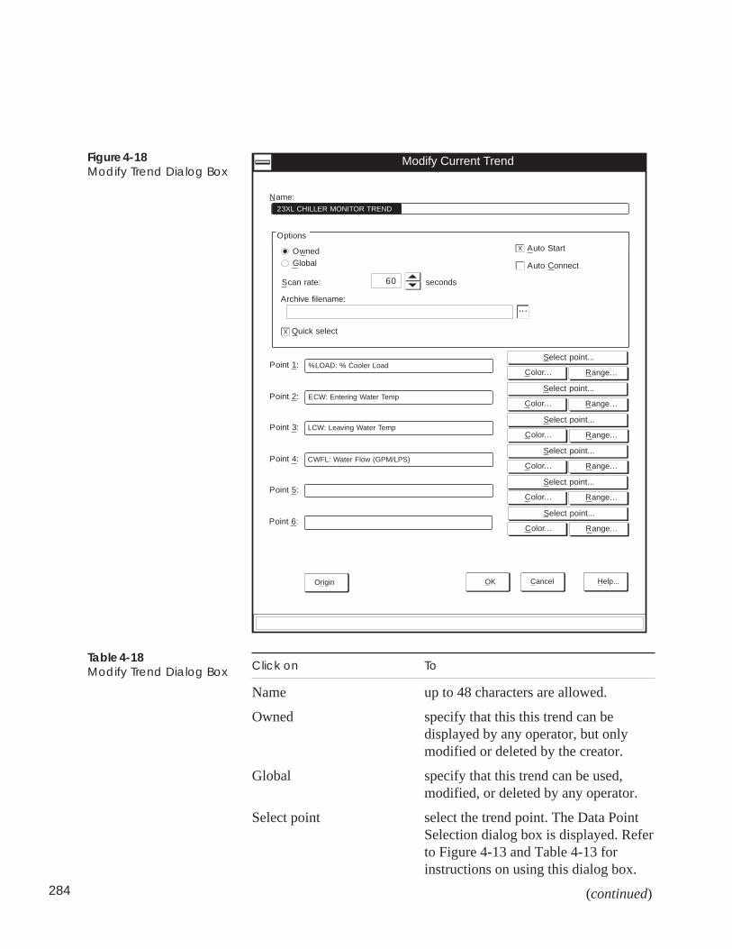
284
Figure 4-18Modify Trend Dialog Box
Click on To
Name up to 48 characters are allowed.
Owned specify that this this trend can bedisplayed by any operator, but onlymodified or deleted by the creator.
Global specify that this trend can be used,modified, or deleted by any operator.
Select point select the trend point. The Data PointSelection dialog box is displayed. Referto Figure 4-13 and Table 4-13 forinstructions on using this dialog box.
(continued)
Table 4-18Modify Trend Dialog Box
Global
Modify Current Trend
Options
OK Cancel Help...
Owned
Name:23XL CHILLER MONITOR TREND
Select point...
Range...Color...
Select point...
Range...Color...
Select point...
Range...Color...
Select point...
Range...Color...
Select point...
Range...Color...
Select point...
Range...Color...
Point 1: %LOAD: % Cooler Load
Point 2: ECW: Entering Water Temp
Point 3:
Point 4:
Point 5:
Point 6:
LCW: Leaving Water Temp
CWFL: Water Flow (GPM/LPS)
Origin
Auto Start
X
Auto Connect
seconds60Scan rate:
Archive filename:
...
Quick selectX
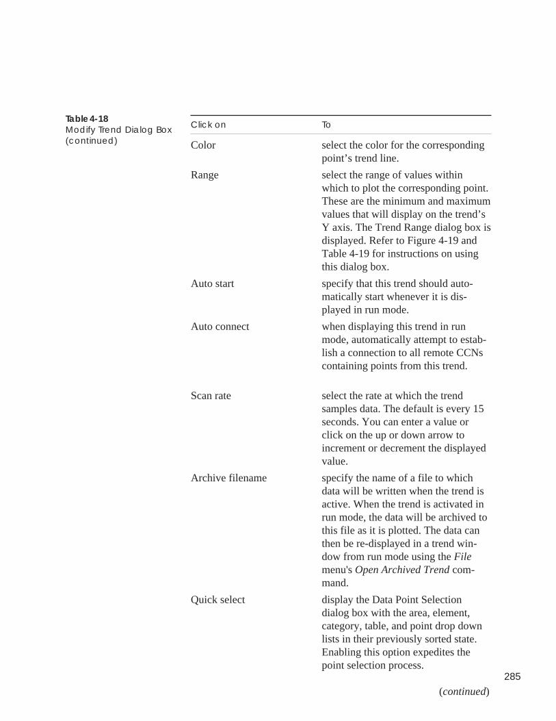
285
Click on To
Color select the color for the correspondingpoint’s trend line.
Range select the range of values withinwhich to plot the corresponding point.These are the minimum and maximumvalues that will display on the trend’sY axis. The Trend Range dialog box isdisplayed. Refer to Figure 4-19 andTable 4-19 for instructions on usingthis dialog box.
Auto start specify that this trend should auto-matically start whenever it is dis-played in run mode.
Auto connect when displaying this trend in runmode, automatically attempt to estab-lish a connection to all remote CCNscontaining points from this trend.
Scan rate select the rate at which the trendsamples data. The default is every 15seconds. You can enter a value orclick on the up or down arrow toincrement or decrement the displayedvalue.
Archive filename specify the name of a file to whichdata will be written when the trend isactive. When the trend is activated inrun mode, the data will be archived tothis file as it is plotted. The data canthen be re-displayed in a trend win-dow from run mode using the Filemenu's Open Archived Trend com-mand.
Quick select display the Data Point Selectiondialog box with the area, element,category, table, and point drop downlists in their previously sorted state.Enabling this option expedites thepoint selection process.
(continued)
Table 4-18Modify Trend Dialog Box(continued)
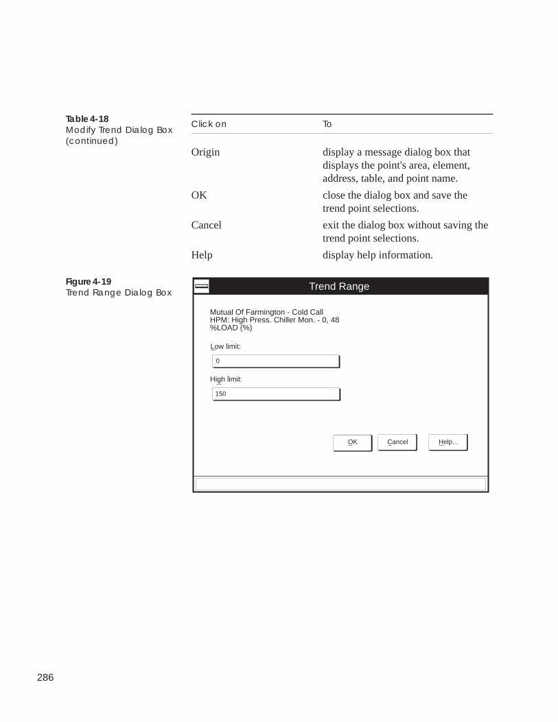
286
Click on To
Origin display a message dialog box thatdisplays the point's area, element,address, table, and point name.
OK close the dialog box and save thetrend point selections.
Cancel exit the dialog box without saving thetrend point selections.
Help display help information.
Table 4-18Modify Trend Dialog Box(continued)
Figure 4-19Trend Range Dialog Box
Trend Range
Low limit:
High limit:
0
150
Mutual Of Farmington - Cold CallHPM: High Press. Chiller Mon. - 0, 48%LOAD (%)
OK Cancel Help...
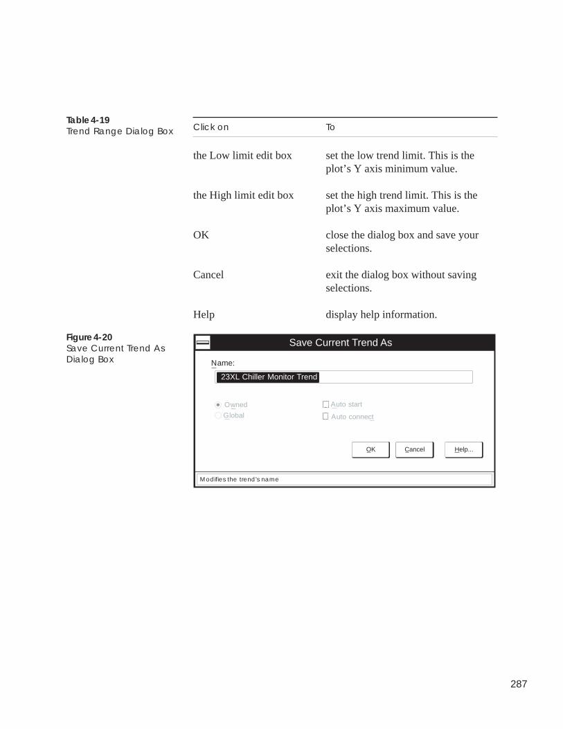
287
Click on To
the Low limit edit box set the low trend limit. This is theplot’s Y axis minimum value.
the High limit edit box set the high trend limit. This is theplot’s Y axis maximum value.
OK close the dialog box and save yourselections.
Cancel exit the dialog box without savingselections.
Help display help information.
Table 4-19Trend Range Dialog Box
Figure 4-20Save Current Trend AsDialog Box
Save Current Trend As
Name:
OK Cancel Help...
Modifies the trend's name
23XL Chiller Monitor Trend
Owned
Global
Auto start
Auto connect
288
Click on To
the Name edit box enter the new trend name. Up to 48 charac-ters are allowed.
Owned allow this trend to be displayed by anyuser, but only modified or deleted by you(the creator) or,
Global allow this trend to be displayed, modified,or deleted by any user.
Auto Start start the trend when it is displayed in runmode.
Auto connect when displaying this trend in run mode,automatically attempt to establish a connec-tion to all remote CCNs containing pointsfrom this trend
OK close the dialog box and save currentsettings.
Cancel exit the dialog box without saving.
Help display help information.
Follow the instructions below to delete a trend from the ComfortVIEWdatabase.
1. Display the trend that you wish to delete. If necessary, refer to theDisplaying and Using Trends section of this chapter.
2. If necessary, switch to design mode. To do this, click on the Runmenu item and then click on Enter design mode.
The WorkSPACE Manager displays a dialog box asking if youwish to reload the current WorkSPACE for design.
3. Click on Yes.
The WorkSPACE Manager enters design mode and the messageDesign displays in the lower right corner of the window.
4. Click on the Edit menu item and then click on Delete ViewSPACE/Trend.
Table 4-20Save Current Trend AsDialog Box
Deleting/Removing TrendsTo Delete a Trend
289
5. In the confirmation dialog box displayed, click on Yes to deletethe trend or on No to prevent its deletion.
The WorkSPACE Manager closes the trend window and deletes thetrend from the ComfortVIEW database.
Follow the instructions below to permanently remove a trend from aWorkSPACE. Note that this function does not delete the trend from theComfortVIEW database. It only removes the selected trend from theselected WorkSPACE.
1. Display the trend that you wish to remove. If necessary, refer tothe Displaying and Using Trends section of this chapter.
2. If necessary, switch to design mode. To do this, click on the Runmenu item and then click on Enter design mode.
The WorkSPACE Manager displays a dialog box asking if youwish to reload the current WorkSPACE for design.
3. Click on Yes.
The WorkSPACE Manager enters design mode and the messageDesign displays in the lower right corner of the window.
4. Click on the Edit menu item and then click on RemoveViewSPACE/Trend.
5. In the confirmation dialog box displayed, click on Yes to removethe trend from the WorkSPACE or on No to prevent its deletion.
6. Save the WorkSPACE by clicking on the File menu item andthen clicking on the Save WorkSPACE command.
Note: You may also perform this command by clicking on theSave WorkSPACE icon in the toolbar.
To Remove a Trend
290
Follow the steps below to establish a telephone connection to orterminate a telephone connection from a remote CCN.
1. Display the ViewSPACE or trend containing the remote CCNpoints you wish to view. If necessary, refer to the Displayingand Using a ViewSPACE or Displaying and Using Trendssections of this chapter.
2. If necessary, enter run mode.
3. Click on the Run menu item and then click on Connect, orclick on the Connect toolbar icon shown at left.
The Connect to dialog box is displayed. This dialog boxdisplays the names of all CCNs associated with points in theactive ViewSPACE or trend. Refer to Table 4-21 and Figure4-21.
Note: If you have only one Autodial Gateway on yourCCN and are currently connected to another remoteCCN, ComfortVIEW displays a message indicatingthat you are unable to connect. Click on OK to closethe message dialog box.
4. In the Select Remote CCNs list, click on the CCN to whichyou wish to connect.
5. Click on OK to connect or click on Cancel to prevent theconnect from taking place.
You are now connected to the remote CCN. The status area to theright of the toolbar displays the connect status. You can now viewall ComfortVIEW data as if you were connected locally.
Connecting to/Disconnectingfrom a RemoteCCN
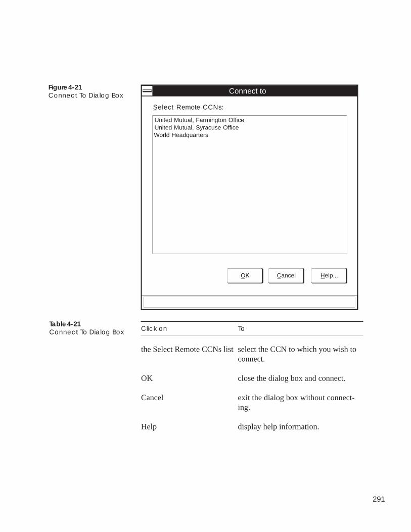
291
Figure 4-21Connect To Dialog Box
Table 4-21Connect To Dialog Box Click on To
the Select Remote CCNs list select the CCN to which you wish toconnect.
OK close the dialog box and connect.
Cancel exit the dialog box without connect-ing.
Help display help information.
Connect to
OK Cancel Help...
Select Remote CCNs:
United Mutual, Farmington OfficeUnited Mutual, Syracuse OfficeWorld Headquarters
292
1. Click on the Run menu item and then click on Disconnect.
The Disconnect From dialog box is displayed. This dialogbox displays the names of all CCNs to which you are cur-rently connected. Refer to Figure 4-22 and Table 4-22.
2. In the Select Remote CCNs list, click on the CCN from whichyou wish to disconnect.
3. Click on OK to disconnect or click on Cancel to prevent thedisconnect from taking place.
You are now disconnected from the remote CCN. The status area tothe right of the toolbar displays the connect status.
Be aware that ComfortVIEW automatically disconnects you from aremote CCN if, after an operator-specified number of minutes, nocommunication occurs (quiet time). The Autodial Gateway willgenerate an alarm to notify you of an automatic disconnect. Foradditional information on the automatic disconnect feature, refer tothe explanation of the Phone Number Configuration dialog box inthe Adding and Modifying CCNs section of this manual’s CarrierNetwork Manager chapter.
To Disconnect from aRemote CCN
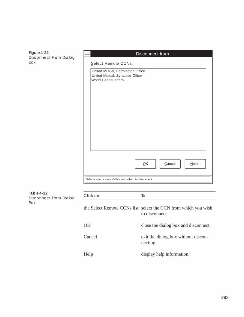
293
Figure 4-22Disconnect From DialogBox
Table 4-22Disconnect From DialogBox
Click on To
the Select Remote CCNs list select the CCN from which you wishto disconnect.
OK close the dialog box and disconnect.
Cancel exit the dialog box without discon-necting.
Help display help information.
Disconnect from
OK Cancel Help...
Select Remote CCNs:
United Mutual, Farmington OfficeUnited Mutual, Syracuse OfficeWorld Headquarters
Selects one or more CCNs from which to disconnect
294
The File menu’s Print command provides you with the capability toprint ViewSPACE and trend windows and definition reports.
Print operation differs depending on whether you select the printcommand from run or from design mode. Selecting the print com-mand from run mode prints a screen captured image of the activeViewSPACE or trend window. Selecting the print command fromdesign mode either prints a screen captured image of the activeViewSPACE or trend window, or prints a WorkSPACE,ViewSPACE, or trend definition report.
Follow the instructions below to print a screen captured image of aselected ViewSPACE or trend.
1. If necessary, enter run mode by clicking on the Run menuitem and then clicking on Start run mode.
2. Display the ViewSPACE or trend that you wish to print. Ifnecessary, refer to the Displaying and Using a ViewSPACEor Displaying and Using Trends section of this chapter.
Note: If you have several ViewSPACEs or trends opened,click on the title bar of the window that you wish toprint.
3. Click on the File menu item and then click on Print.
Note: You may also perform this command by clicking onthe Print icon in the toolbar.
A confirmation dialog box is displayed asking if you wish toprint the active ViewSPACE or trend.
4. Click on Yes.
The ViewSPACE or trend will print on the printer that you havedesignated using the File menu’s Print setup command.
PrintingViewSPACEs andTrends
Run Mode — Printing aViewSPACE or TrendWindow
295
Design Mode —Printing a ViewSPACEor Trend Window orPrinting a WorkSPACE,ViewSPACE, or TrendDefinition Report
Follow the instructions below to print a screen captured image of aselected ViewSPACE or trend window, or to print a definitionreport. You can also print definition reports for a WorkSPACE,ViewSPACE or trend.
1. If necessary, enter design mode by clicking on the Run menuitem and then clicking on Stop run mode.
2. Display the WorkSPACE, ViewSPACE, or trend that youwish to print. If necessary, refer to Accessing theWorkSPACE Manager, Displaying and Using a ViewSPACE,and Displaying and Using Trends.
Note: If you have several ViewSPACEs or trends opened,click on the title bar of the window that you wish toprint.
3. Click on the File menu item and then click on Print.
Note: You may also perform this command by clicking onthe Print icon in the toolbar.
The Print Options dialog box is displayed.
4. Click on Selected ViewSPACE/Trend if you wish to print theselected ViewSPACE or trend window.
5. To print a definition report, click on Custom Print and thenclick on one of the following to enable or disable the defini-tion you wish to print: WorkSPACE, ViewSPACE, or trend.
6. Click on OK to print the selected ViewSPACE, trend, orreport definition, oron Cancel to exit the dialog box without printing.
The image or report definition will print on the printer that you havedesignated using the File menu’s Print setup command. SampleWorkSPACE, ViewSPACE, and trend definitions appear in Figures4-24, 4-25, and 4-26.
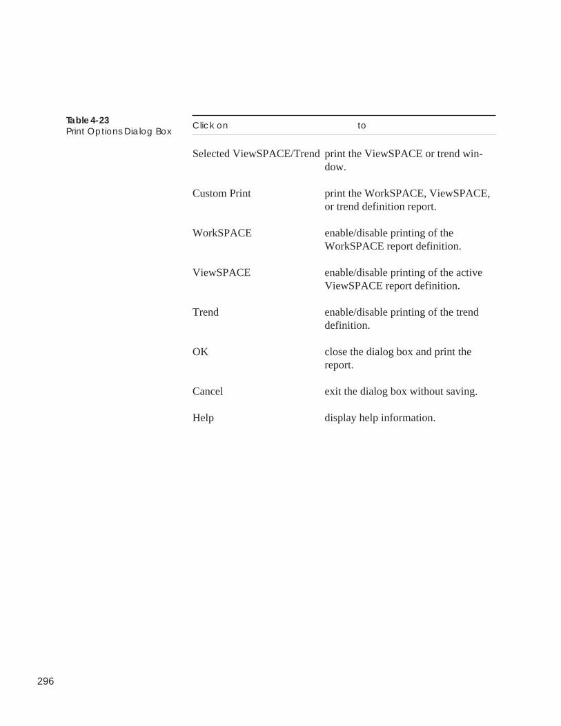
296
Click on to
Selected ViewSPACE/Trend print the ViewSPACE or trend win-dow.
Custom Print print the WorkSPACE, ViewSPACE,or trend definition report.
WorkSPACE enable/disable printing of theWorkSPACE report definition.
ViewSPACE enable/disable printing of the activeViewSPACE report definition.
Trend enable/disable printing of the trenddefinition.
OK close the dialog box and print thereport.
Cancel exit the dialog box without saving.
Help display help information.
Table 4-23Print Options Dialog Box
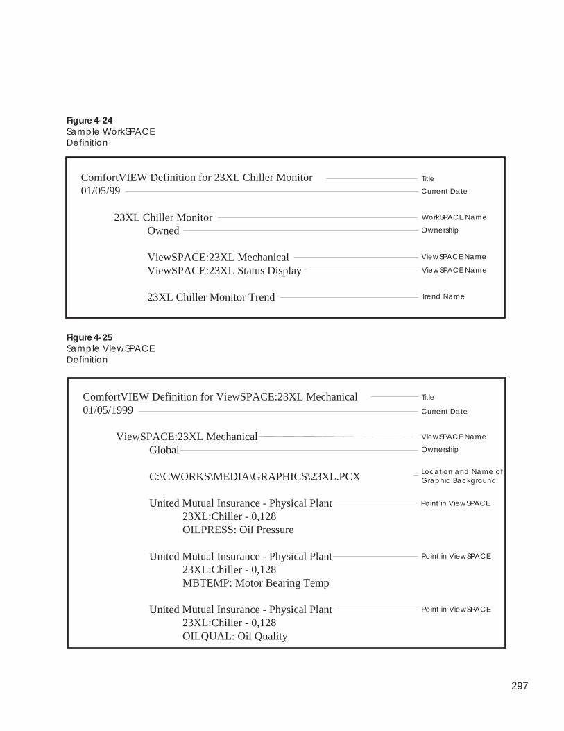
297
ComfortVIEW Definition for 23XL Chiller Monitor01/05/99
23XL Chiller MonitorOwned
ViewSPACE:23XL MechanicalViewSPACE:23XL Status Display
23XL Chiller Monitor Trend
Figure 4-24Sample WorkSPACEDefinition
Figure 4-25Sample ViewSPACEDefinition
ComfortVIEW Definition for ViewSPACE:23XL Mechanical01/05/1999
ViewSPACE:23XL MechanicalGlobal
C:\CWORKS\MEDIA\GRAPHICS\23XL.PCX
United Mutual Insurance - Physical Plant23XL:Chiller - 0,128OILPRESS: Oil Pressure
United Mutual Insurance - Physical Plant23XL:Chiller - 0,128MBTEMP: Motor Bearing Temp
United Mutual Insurance - Physical Plant23XL:Chiller - 0,128OILQUAL: Oil Quality
Title
Current Date
ViewSPACE Name
Ownership
Location and Name ofGraphic Background
Point in ViewSPACE
Point in ViewSPACE
Point in ViewSPACE
Title
Current Date
WorkSPACE Name
Ownership
ViewSPACE Name
ViewSPACE Name
Trend Name
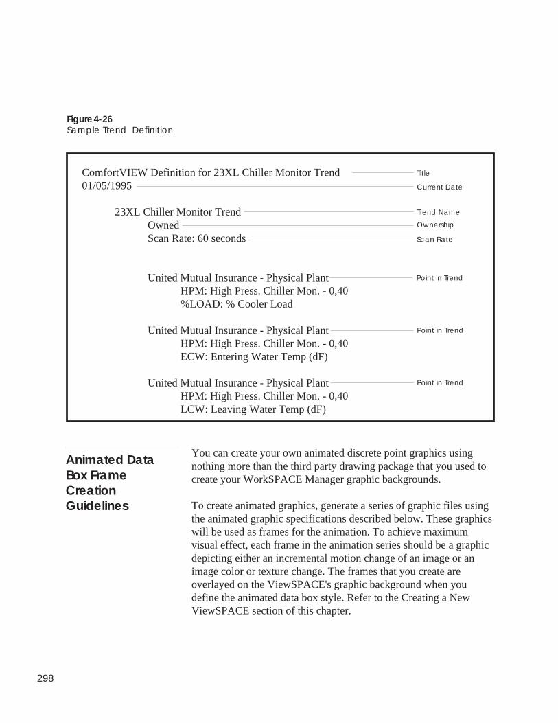
298
Figure 4-26Sample Trend Definition
ComfortVIEW Definition for 23XL Chiller Monitor Trend01/05/1995
23XL Chiller Monitor TrendOwnedScan Rate: 60 seconds
United Mutual Insurance - Physical PlantHPM: High Press. Chiller Mon. - 0,40%LOAD: % Cooler Load
United Mutual Insurance - Physical PlantHPM: High Press. Chiller Mon. - 0,40ECW: Entering Water Temp (dF)
United Mutual Insurance - Physical PlantHPM: High Press. Chiller Mon. - 0,40LCW: Leaving Water Temp (dF)
Title
Current Date
Trend Name
Ownership
Point in Trend
Point in Trend
Point in Trend
Scan Rate
Animated DataBox FrameCreationGuidelines
You can create your own animated discrete point graphics usingnothing more than the third party drawing package that you used tocreate your WorkSPACE Manager graphic backgrounds.
To create animated graphics, generate a series of graphic files usingthe animated graphic specifications described below. These graphicswill be used as frames for the animation. To achieve maximumvisual effect, each frame in the animation series should be a graphicdepicting either an incremental motion change of an image or animage color or texture change. The frames that you create areoverlayed on the ViewSPACE's graphic background when youdefine the animated data box style. Refer to the Creating a NewViewSPACE section of this chapter.
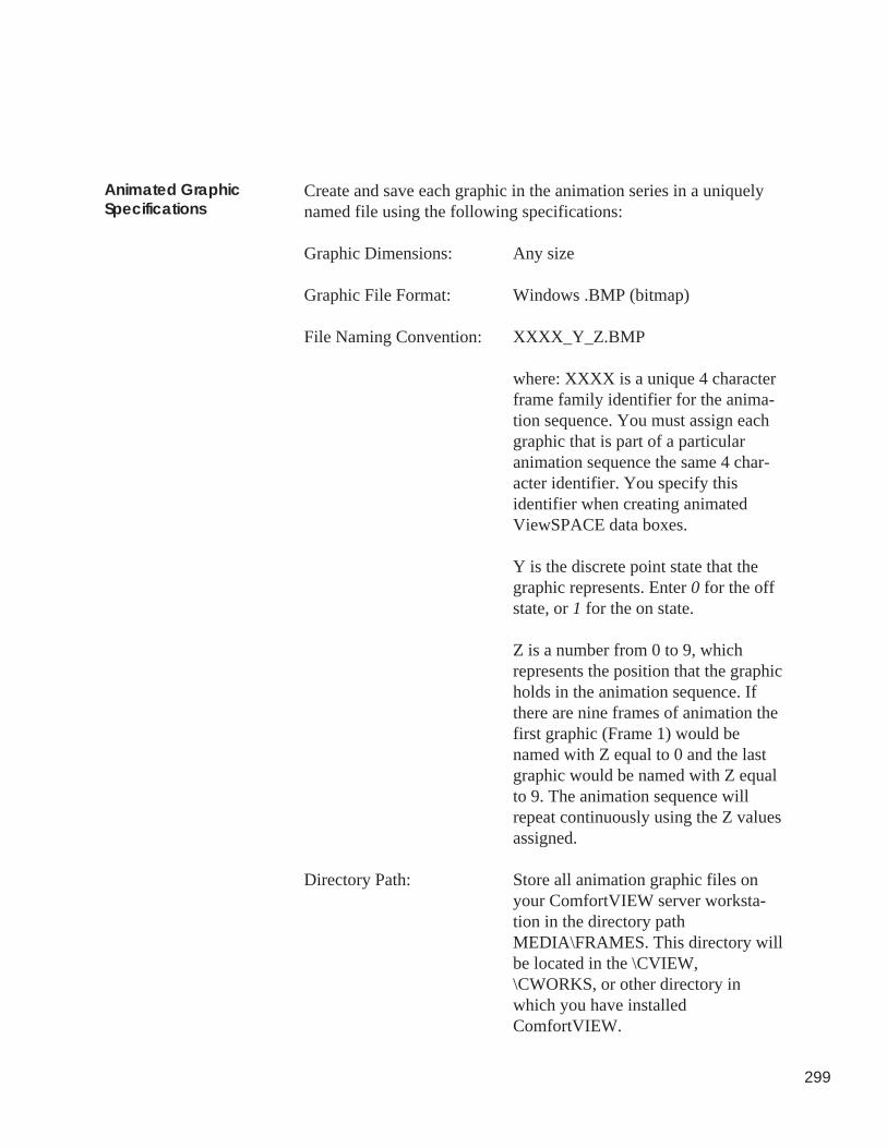
299
Animated GraphicSpecifications
Create and save each graphic in the animation series in a uniquelynamed file using the following specifications:
Graphic Dimensions: Any size
Graphic File Format: Windows .BMP (bitmap)
File Naming Convention: XXXX_Y_Z.BMP
where: XXXX is a unique 4 characterframe family identifier for the anima-tion sequence. You must assign eachgraphic that is part of a particularanimation sequence the same 4 char-acter identifier. You specify thisidentifier when creating animatedViewSPACE data boxes.
Y is the discrete point state that thegraphic represents. Enter 0 for the offstate, or 1 for the on state.
Z is a number from 0 to 9, whichrepresents the position that the graphicholds in the animation sequence. Ifthere are nine frames of animation thefirst graphic (Frame 1) would benamed with Z equal to 0 and the lastgraphic would be named with Z equalto 9. The animation sequence willrepeat continuously using the Z valuesassigned.
Directory Path: Store all animation graphic files onyour ComfortVIEW server worksta-tion in the directory pathMEDIA\FRAMES. This directory willbe located in the \CVIEW,\CWORKS, or other directory inwhich you have installedComfortVIEW.
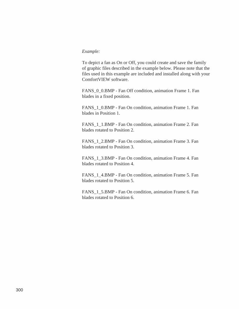
300
Example:
To depict a fan as On or Off, you could create and save the familyof graphic files described in the example below. Please note that thefiles used in this example are included and installed along with yourComfortVIEW software.
FANS_0_0.BMP - Fan Off condition, animation Frame 1. Fanblades in a fixed position.
FANS_1_0.BMP - Fan On condition, animation Frame 1. Fanblades in Position 1.
FANS_1_1.BMP - Fan On condition, animation Frame 2. Fanblades rotated to Position 2.
FANS_1_2.BMP - Fan On condition, animation Frame 3. Fanblades rotated to Position 3.
FANS_1_3.BMP - Fan On condition, animation Frame 4. Fanblades rotated to Position 4.
FANS_1_4.BMP - Fan On condition, animation Frame 5. Fanblades rotated to Position 5.
FANS_1_5.BMP - Fan On condition, animation Frame 6. Fanblades rotated to Position 6.
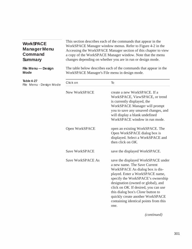
301
WorkSPACEManager MenuCommandSummary
This section describes each of the commands that appear in theWorkSPACE Manager window menus. Refer to Figure 4-2 in theAccessing the WorkSPACE Manager section of this chapter to viewa copy of the WorkSPACE Manager window. Note that the menuchanges depending on whether you are in run or design mode.
The table below describes each of the commands that appear in theWorkSPACE Manager's File menu in design mode.
Click on To
New WorkSPACE create a new WorkSPACE. If aWorkSPACE, ViewSPACE, or trendis currently displayed, theWorkSPACE Manager will promptyou to save any unsaved changes, andwill display a blank undefinedWorkSPACE window in run mode.
Open WorkSPACE open an existing WorkSPACE. TheOpen WorkSPACE dialog box isdisplayed. Select a WorkSPACE andthen click on OK.
Save WorkSPACE save the displayed WorkSPACE.
Save WorkSPACE As save the displayed WorkSPACE undera new name. The Save CurrentWorkSPACE As dialog box is dis-played. Enter a WorkSPACE name,specify the WorkSPACE’s ownershipdesignation (owned or global), andclick on OK. If desired, you can usethis dialog box's Clone button toquickly create another WorkSPACEcontaining identical points from thisone.
(continued)
Table 4-27File Menu - Design Mode
File Menu — DesignMode
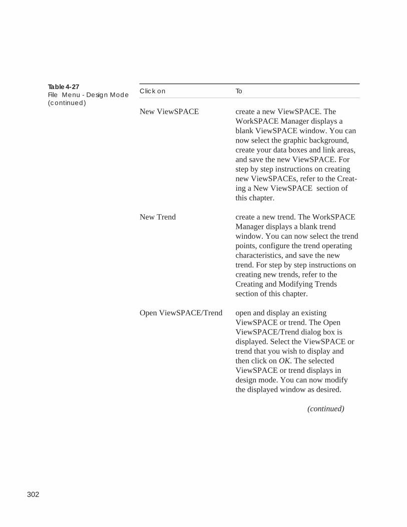
302
Table 4-27File Menu - Design Mode(continued)
Click on To
New ViewSPACE create a new ViewSPACE. TheWorkSPACE Manager displays ablank ViewSPACE window. You cannow select the graphic background,create your data boxes and link areas,and save the new ViewSPACE. Forstep by step instructions on creatingnew ViewSPACEs, refer to the Creat-ing a New ViewSPACE section ofthis chapter.
New Trend create a new trend. The WorkSPACEManager displays a blank trendwindow. You can now select the trendpoints, configure the trend operatingcharacteristics, and save the newtrend. For step by step instructions oncreating new trends, refer to theCreating and Modifying Trendssection of this chapter.
Open ViewSPACE/Trend open and display an existingViewSPACE or trend. The OpenViewSPACE/Trend dialog box isdisplayed. Select the ViewSPACE ortrend that you wish to display andthen click on OK. The selectedViewSPACE or trend displays indesign mode. You can now modifythe displayed window as desired.
(continued)
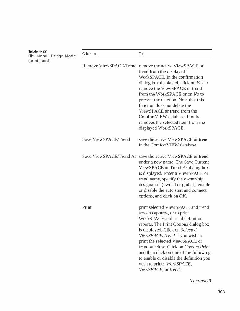
303
Table 4-27File Menu - Design Mode(continued)
Click on To
Remove ViewSPACE/Trend remove the active ViewSPACE ortrend from the displayedWorkSPACE. In the confirmationdialog box displayed, click on Yes toremove the ViewSPACE or trendfrom the WorkSPACE or on No toprevent the deletion. Note that thisfunction does not delete theViewSPACE or trend from theComfortVIEW database. It onlyremoves the selected item from thedisplayed WorkSPACE.
Save ViewSPACE/Trend save the active ViewSPACE or trendin the ComfortVIEW database.
Save ViewSPACE/Trend As save the active ViewSPACE or trendunder a new name. The Save CurrentViewSPACE or Trend As dialog boxis displayed. Enter a ViewSPACE ortrend name, specify the ownershipdesignation (owned or global), enableor disable the auto start and connectoptions, and click on OK.
Print print selected ViewSPACE and trendscreen captures, or to printWorkSPACE and trend definitionreports. The Print Options dialog boxis displayed. Click on SelectedViewSPACE/Trend if you wish toprint the selected ViewSPACE ortrend window. Click on Custom Printand then click on one of the followingto enable or disable the definition youwish to print: WorkSPACE,ViewSPACE, or trend.
(continued)
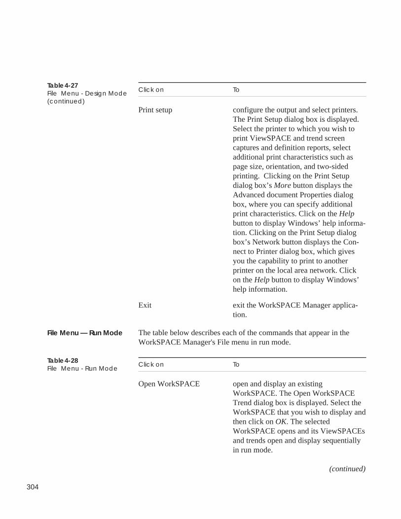
304
Table 4-27File Menu - Design Mode(continued)
Click on To
Print setup configure the output and select printers.The Print Setup dialog box is displayed.Select the printer to which you wish toprint ViewSPACE and trend screencaptures and definition reports, selectadditional print characteristics such aspage size, orientation, and two-sidedprinting. Clicking on the Print Setupdialog box’s More button displays theAdvanced document Properties dialogbox, where you can specify additionalprint characteristics. Click on the Helpbutton to display Windows’ help informa-tion. Clicking on the Print Setup dialogbox’s Network button displays the Con-nect to Printer dialog box, which givesyou the capability to print to anotherprinter on the local area network. Clickon the Help button to display Windows’help information.
Exit exit the WorkSPACE Manager applica-tion.
The table below describes each of the commands that appear in theWorkSPACE Manager's File menu in run mode.
Click on To
Open WorkSPACE open and display an existingWorkSPACE. The Open WorkSPACETrend dialog box is displayed. Select theWorkSPACE that you wish to display andthen click on OK. The selectedWorkSPACE opens and its ViewSPACEsand trends open and display sequentiallyin run mode.
(continued)
File Menu — Run Mode
Table 4-28File Menu - Run Mode
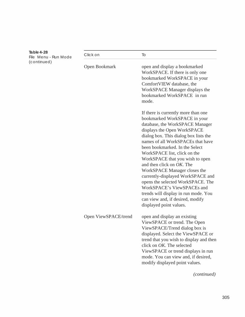
305
Table 4-28File Menu - Run Mode(continued)
Click on To
Open Bookmark open and display a bookmarkedWorkSPACE. If there is only onebookmarked WorkSPACE in yourComfortVIEW database, theWorkSPACE Manager displays thebookmarked WorkSPACE in runmode.
If there is currently more than onebookmarked WorkSPACE in yourdatabase, the WorkSPACE Managerdisplays the Open WorkSPACEdialog box. This dialog box lists thenames of all WorkSPACEs that havebeen bookmarked. In the SelectWorkSPACE list, click on theWorkSPACE that you wish to openand then click on OK. TheWorkSPACE Manager closes thecurrently-displayed WorkSPACE andopens the selected WorkSPACE. TheWorkSPACE’s ViewSPACEs andtrends will display in run mode. Youcan view and, if desired, modifydisplayed point values.
Open ViewSPACE/trend open and display an existingViewSPACE or trend. The OpenViewSPACE/Trend dialog box isdisplayed. Select the ViewSPACE ortrend that you wish to display and thenclick on OK. The selectedViewSPACE or trend displays in runmode. You can view and, if desired,modify displayed point values.
(continued)
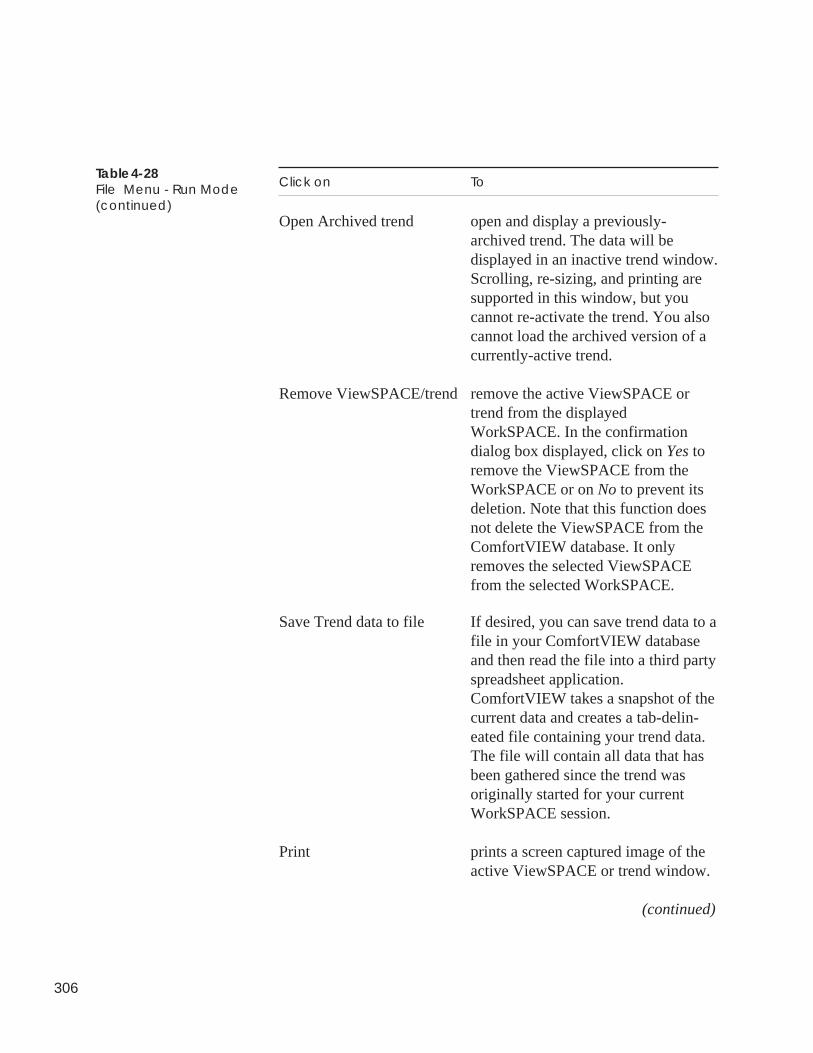
306
Table 4-28File Menu - Run Mode(continued)
Click on To
Open Archived trend open and display a previously-archived trend. The data will bedisplayed in an inactive trend window.Scrolling, re-sizing, and printing aresupported in this window, but youcannot re-activate the trend. You alsocannot load the archived version of acurrently-active trend.
Remove ViewSPACE/trend remove the active ViewSPACE ortrend from the displayedWorkSPACE. In the confirmationdialog box displayed, click on Yes toremove the ViewSPACE from theWorkSPACE or on No to prevent itsdeletion. Note that this function doesnot delete the ViewSPACE from theComfortVIEW database. It onlyremoves the selected ViewSPACEfrom the selected WorkSPACE.
Save Trend data to file If desired, you can save trend data to afile in your ComfortVIEW databaseand then read the file into a third partyspreadsheet application.ComfortVIEW takes a snapshot of thecurrent data and creates a tab-delin-eated file containing your trend data.The file will contain all data that hasbeen gathered since the trend wasoriginally started for your currentWorkSPACE session.
Print prints a screen captured image of theactive ViewSPACE or trend window.
(continued)
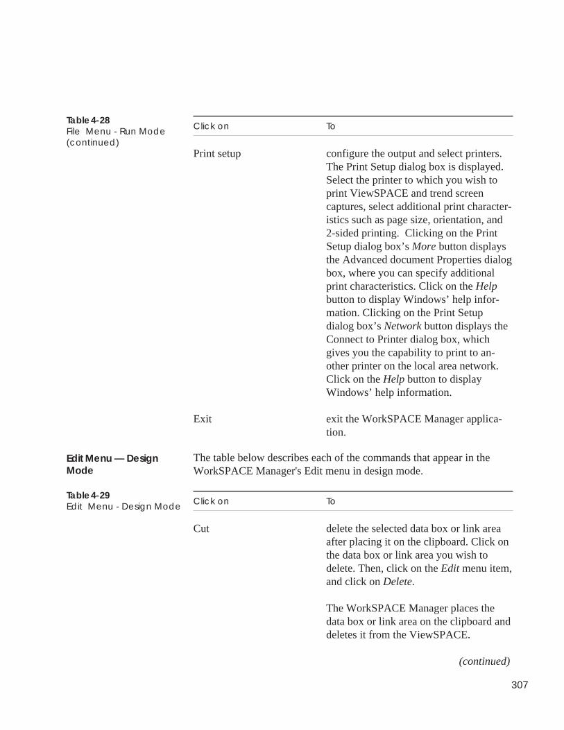
307
Click on To
Print setup configure the output and select printers.The Print Setup dialog box is displayed.Select the printer to which you wish toprint ViewSPACE and trend screencaptures, select additional print character-istics such as page size, orientation, and2-sided printing. Clicking on the PrintSetup dialog box’s More button displaysthe Advanced document Properties dialogbox, where you can specify additionalprint characteristics. Click on the Helpbutton to display Windows’ help infor-mation. Clicking on the Print Setupdialog box’s Network button displays theConnect to Printer dialog box, whichgives you the capability to print to an-other printer on the local area network.Click on the Help button to displayWindows’ help information.
Exit exit the WorkSPACE Manager applica-tion.
The table below describes each of the commands that appear in theWorkSPACE Manager's Edit menu in design mode.
Click on To
Cut delete the selected data box or link areaafter placing it on the clipboard. Click onthe data box or link area you wish todelete. Then, click on the Edit menu item,and click on Delete.
The WorkSPACE Manager places thedata box or link area on the clipboard anddeletes it from the ViewSPACE.
(continued)
Table 4-28File Menu - Run Mode(continued)
Edit Menu — DesignMode
Table 4-29Edit Menu - Design Mode
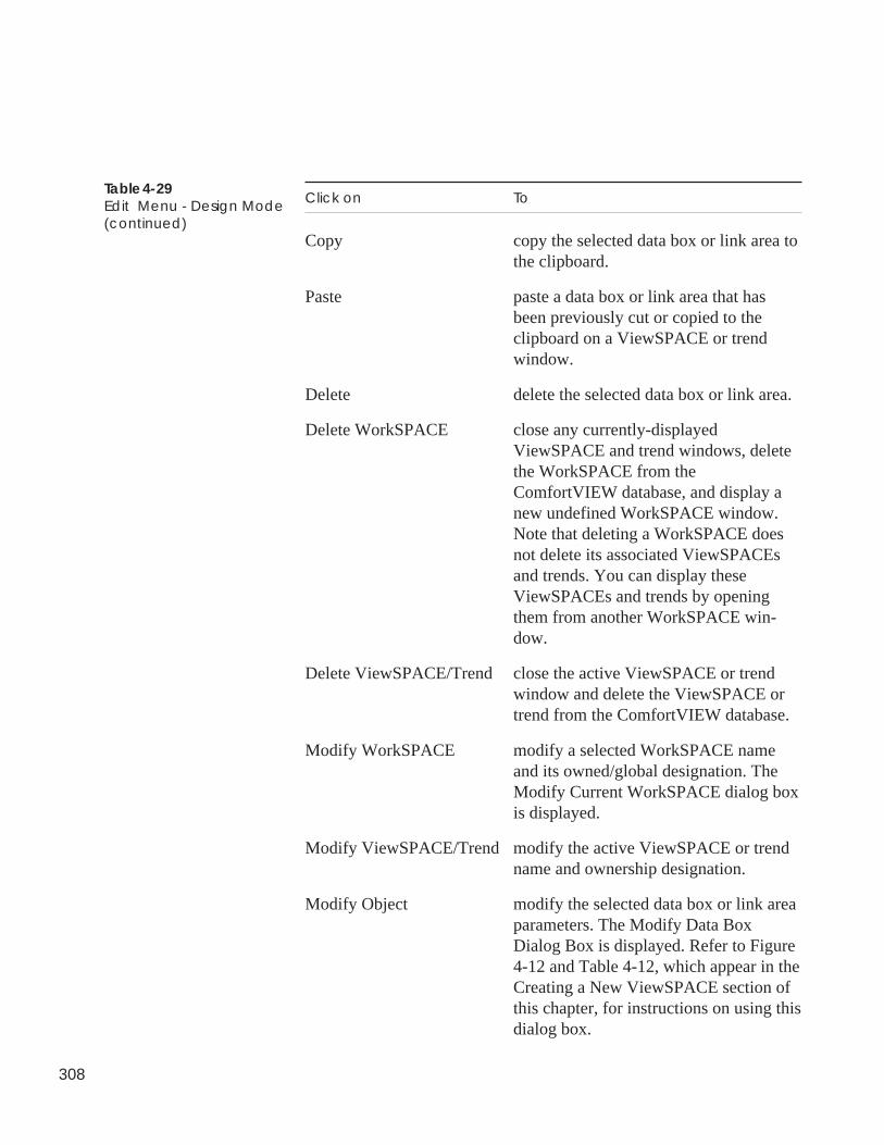
308
Table 4-29Edit Menu - Design Mode(continued)
Click on To
Copy copy the selected data box or link area tothe clipboard.
Paste paste a data box or link area that hasbeen previously cut or copied to theclipboard on a ViewSPACE or trendwindow.
Delete delete the selected data box or link area.
Delete WorkSPACE close any currently-displayedViewSPACE and trend windows, deletethe WorkSPACE from theComfortVIEW database, and display anew undefined WorkSPACE window.Note that deleting a WorkSPACE doesnot delete its associated ViewSPACEsand trends. You can display theseViewSPACEs and trends by openingthem from another WorkSPACE win-dow.
Delete ViewSPACE/Trend close the active ViewSPACE or trendwindow and delete the ViewSPACE ortrend from the ComfortVIEW database.
Modify WorkSPACE modify a selected WorkSPACE nameand its owned/global designation. TheModify Current WorkSPACE dialog boxis displayed.
Modify ViewSPACE/Trend modify the active ViewSPACE or trendname and ownership designation.
Modify Object modify the selected data box or link areaparameters. The Modify Data BoxDialog Box is displayed. Refer to Figure4-12 and Table 4-12, which appear in theCreating a New ViewSPACE section ofthis chapter, for instructions on using thisdialog box.
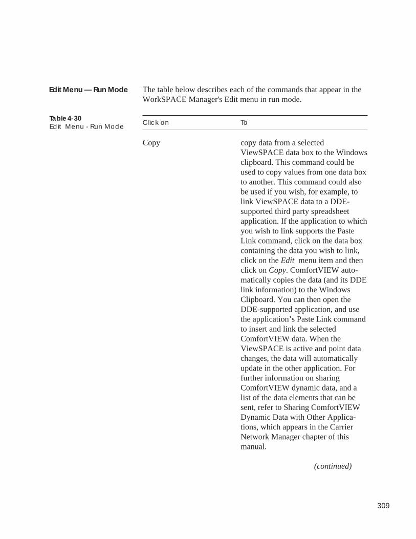
309
The table below describes each of the commands that appear in theWorkSPACE Manager's Edit menu in run mode.
Click on To
Copy copy data from a selectedViewSPACE data box to the Windowsclipboard. This command could beused to copy values from one data boxto another. This command could alsobe used if you wish, for example, tolink ViewSPACE data to a DDE-supported third party spreadsheetapplication. If the application to whichyou wish to link supports the PasteLink command, click on the data boxcontaining the data you wish to link,click on the Edit menu item and thenclick on Copy. ComfortVIEW auto-matically copies the data (and its DDElink information) to the WindowsClipboard. You can then open theDDE-supported application, and usethe application’s Paste Link commandto insert and link the selectedComfortVIEW data. When theViewSPACE is active and point datachanges, the data will automaticallyupdate in the other application. Forfurther information on sharingComfortVIEW dynamic data, and alist of the data elements that can besent, refer to Sharing ComfortVIEWDynamic Data with Other Applica-tions, which appears in the CarrierNetwork Manager chapter of thismanual.
(continued)
Edit Menu — Run Mode
Table 4-30Edit Menu - Run Mode
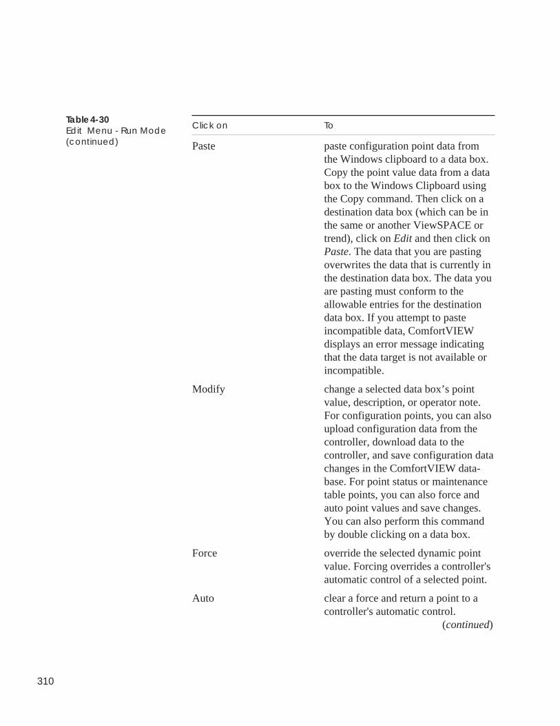
310
Table 4-30Edit Menu - Run Mode(continued)
Click on To
Paste paste configuration point data fromthe Windows clipboard to a data box.Copy the point value data from a databox to the Windows Clipboard usingthe Copy command. Then click on adestination data box (which can be inthe same or another ViewSPACE ortrend), click on Edit and then click onPaste. The data that you are pastingoverwrites the data that is currently inthe destination data box. The data youare pasting must conform to theallowable entries for the destinationdata box. If you attempt to pasteincompatible data, ComfortVIEWdisplays an error message indicatingthat the data target is not available orincompatible.
Modify change a selected data box’s pointvalue, description, or operator note.For configuration points, you can alsoupload configuration data from thecontroller, download data to thecontroller, and save configuration datachanges in the ComfortVIEW data-base. For point status or maintenancetable points, you can also force andauto point values and save changes.You can also perform this commandby double clicking on a data box.
Force override the selected dynamic pointvalue. Forcing overrides a controller'sautomatic control of a selected point.
Auto clear a force and return a point to acontroller's automatic control.
(continued)
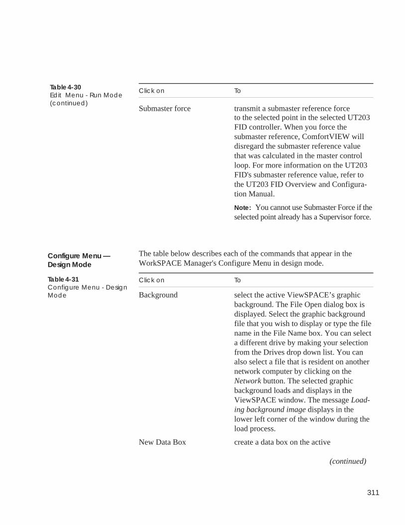
311
Click on To
Submaster force transmit a submaster reference forceto the selected point in the selected UT203FID controller. When you force thesubmaster reference, ComfortVIEW willdisregard the submaster reference valuethat was calculated in the master controlloop. For more information on the UT203FID's submaster reference value, refer tothe UT203 FID Overview and Configura-tion Manual.
Note: You cannot use Submaster Force if theselected point already has a Supervisor force.
The table below describes each of the commands that appear in theWorkSPACE Manager's Configure Menu in design mode.
Click on To
Background select the active ViewSPACE’s graphicbackground. The File Open dialog box isdisplayed. Select the graphic backgroundfile that you wish to display or type the filename in the File Name box. You can selecta different drive by making your selectionfrom the Drives drop down list. You canalso select a file that is resident on anothernetwork computer by clicking on theNetwork button. The selected graphicbackground loads and displays in theViewSPACE window. The message Load-ing background image displays in thelower left corner of the window during theload process.
New Data Box create a data box on the active
(continued)
Table 4-31Configure Menu - DesignMode
Table 4-30Edit Menu - Run Mode(continued)
Configure Menu —Design Mode
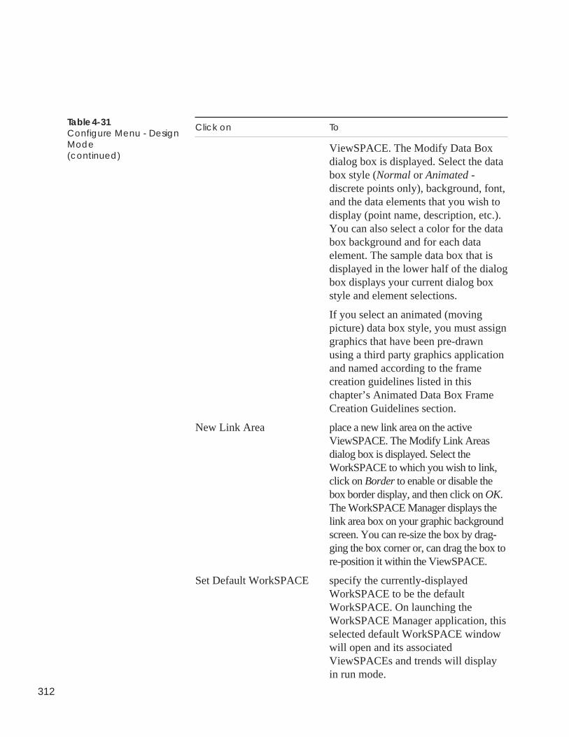
312
Click on To
ViewSPACE. The Modify Data Boxdialog box is displayed. Select the databox style (Normal or Animated -discrete points only), background, font,and the data elements that you wish todisplay (point name, description, etc.).You can also select a color for the databox background and for each dataelement. The sample data box that isdisplayed in the lower half of the dialogbox displays your current dialog boxstyle and element selections.
If you select an animated (movingpicture) data box style, you must assigngraphics that have been pre-drawnusing a third party graphics applicationand named according to the framecreation guidelines listed in thischapter’s Animated Data Box FrameCreation Guidelines section.
New Link Area place a new link area on the activeViewSPACE. The Modify Link Areasdialog box is displayed. Select theWorkSPACE to which you wish to link,click on Border to enable or disable thebox border display, and then click on OK.The WorkSPACE Manager displays thelink area box on your graphic backgroundscreen. You can re-size the box by drag-ging the box corner or, can drag the box tore-position it within the ViewSPACE.
Set Default WorkSPACE specify the currently-displayedWorkSPACE to be the defaultWorkSPACE. On launching theWorkSPACE Manager application, thisselected default WorkSPACE windowwill open and its associatedViewSPACEs and trends will displayin run mode.
Table 4-31Configure Menu - DesignMode(continued)
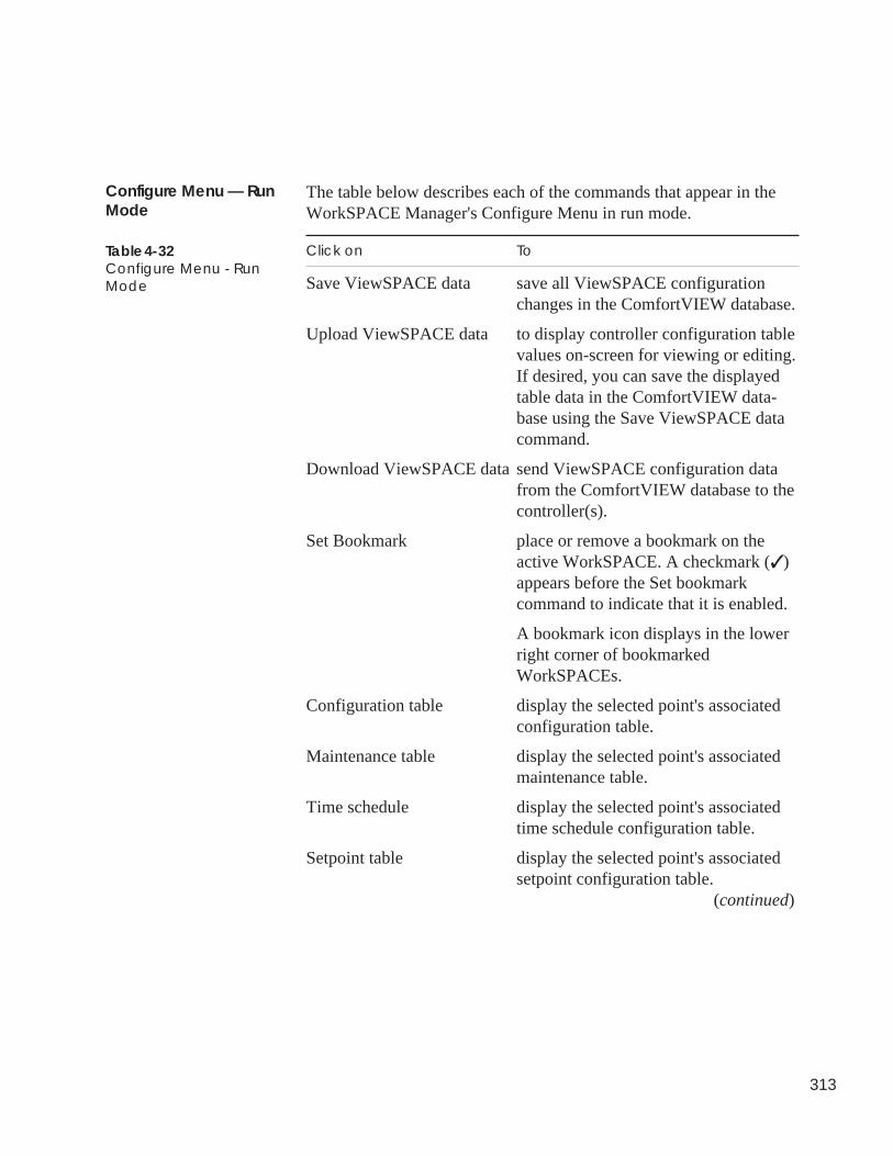
313
The table below describes each of the commands that appear in theWorkSPACE Manager's Configure Menu in run mode.
Click on To
Save ViewSPACE data save all ViewSPACE configurationchanges in the ComfortVIEW database.
Upload ViewSPACE data to display controller configuration tablevalues on-screen for viewing or editing.If desired, you can save the displayedtable data in the ComfortVIEW data-base using the Save ViewSPACE datacommand.
Download ViewSPACE data send ViewSPACE configuration datafrom the ComfortVIEW database to thecontroller(s).
Set Bookmark place or remove a bookmark on theactive WorkSPACE. A checkmark (✓ )appears before the Set bookmarkcommand to indicate that it is enabled.
A bookmark icon displays in the lowerright corner of bookmarkedWorkSPACEs.
Configuration table display the selected point's associatedconfiguration table.
Maintenance table display the selected point's associatedmaintenance table.
Time schedule display the selected point's associatedtime schedule configuration table.
Setpoint table display the selected point's associatedsetpoint configuration table.
(continued)
Configure Menu — RunMode
Table 4-32Configure Menu - RunMode
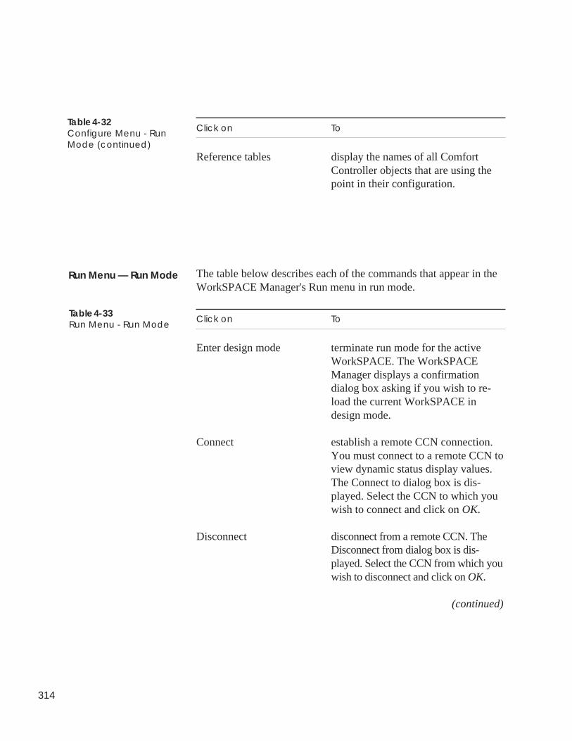
314
Click on To
Reference tables display the names of all ComfortController objects that are using thepoint in their configuration.
The table below describes each of the commands that appear in theWorkSPACE Manager's Run menu in run mode.
Click on To
Enter design mode terminate run mode for the activeWorkSPACE. The WorkSPACEManager displays a confirmationdialog box asking if you wish to re-load the current WorkSPACE indesign mode.
Connect establish a remote CCN connection.You must connect to a remote CCN toview dynamic status display values.The Connect to dialog box is dis-played. Select the CCN to which youwish to connect and click on OK.
Disconnect disconnect from a remote CCN. TheDisconnect from dialog box is dis-played. Select the CCN from which youwish to disconnect and click on OK.
(continued)
Table 4-32Configure Menu - RunMode (continued)
Table 4-33Run Menu - Run Mode
Run Menu — Run Mode
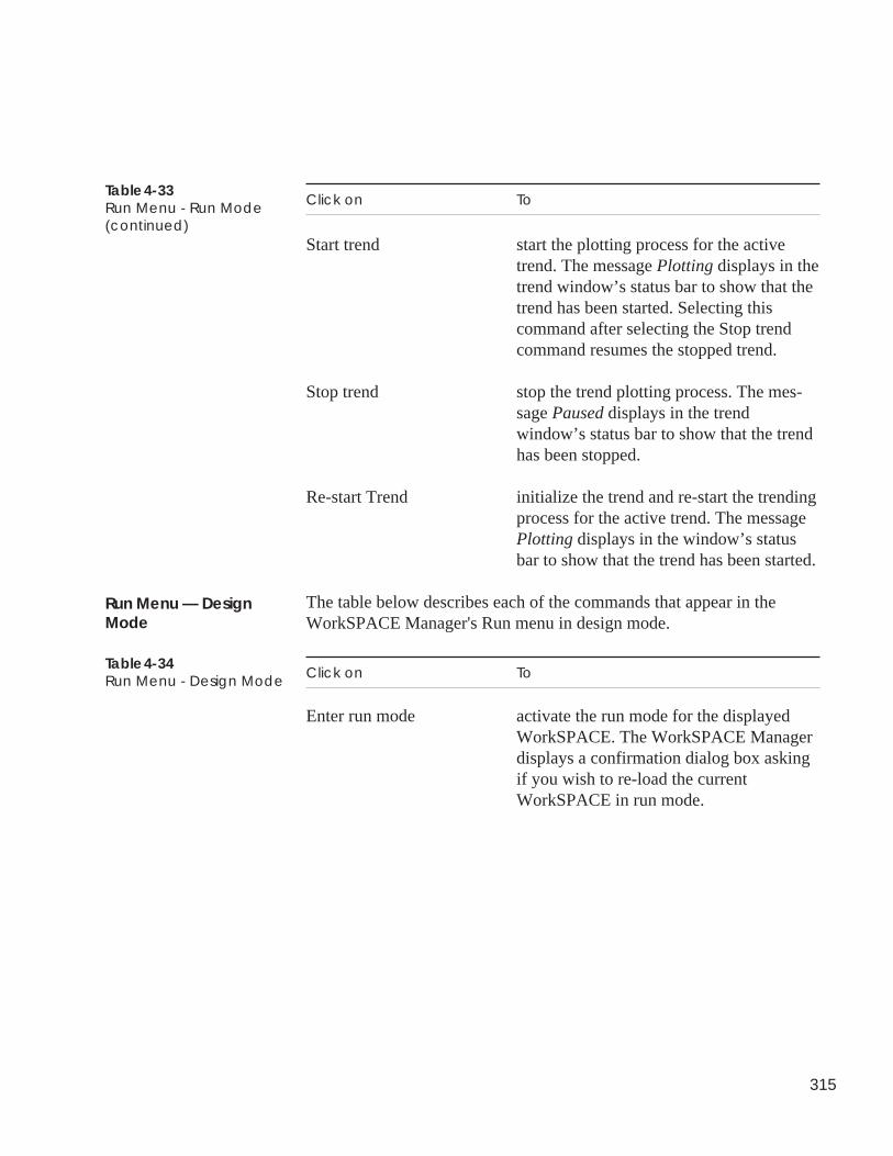
315
Click on To
Start trend start the plotting process for the activetrend. The message Plotting displays in thetrend window’s status bar to show that thetrend has been started. Selecting thiscommand after selecting the Stop trendcommand resumes the stopped trend.
Stop trend stop the trend plotting process. The mes-sage Paused displays in the trendwindow’s status bar to show that the trendhas been stopped.
Re-start Trend initialize the trend and re-start the trendingprocess for the active trend. The messagePlotting displays in the window’s statusbar to show that the trend has been started.
The table below describes each of the commands that appear in theWorkSPACE Manager's Run menu in design mode.
Click on To
Enter run mode activate the run mode for the displayedWorkSPACE. The WorkSPACE Managerdisplays a confirmation dialog box askingif you wish to re-load the currentWorkSPACE in run mode.
Table 4-33Run Menu - Run Mode(continued)
Run Menu — DesignMode
Table 4-34Run Menu - Design Mode
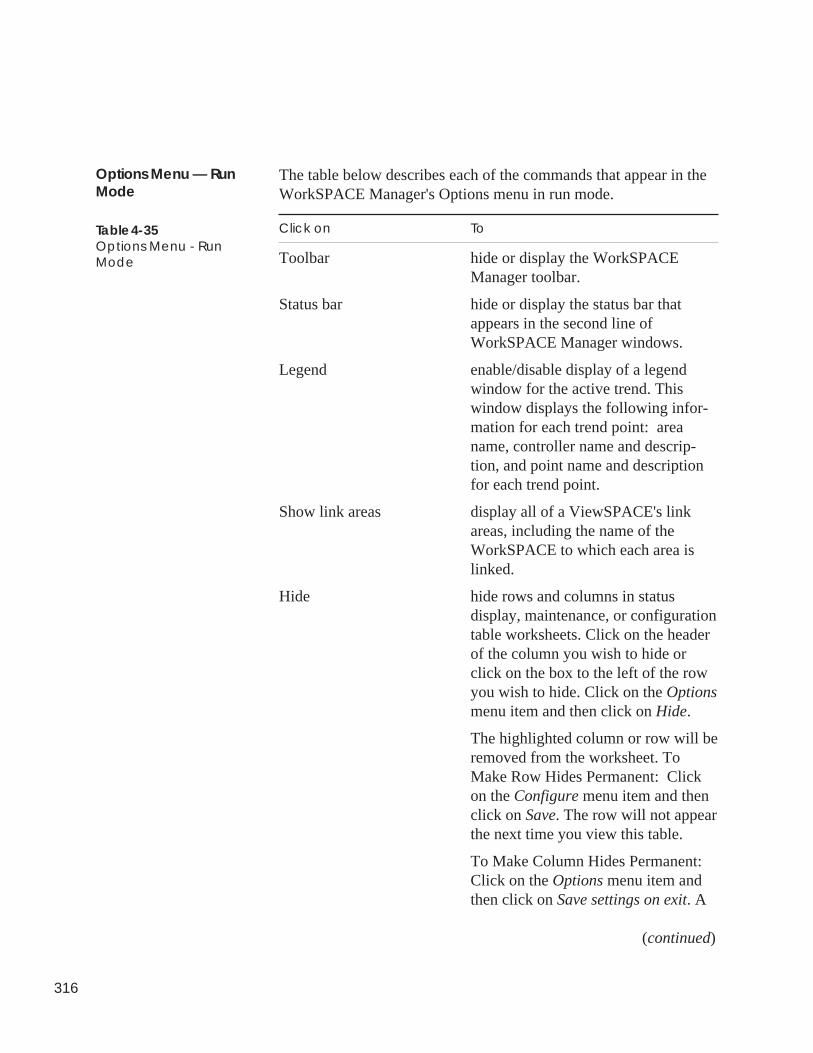
316
The table below describes each of the commands that appear in theWorkSPACE Manager's Options menu in run mode.
Click on To
Toolbar hide or display the WorkSPACEManager toolbar.
Status bar hide or display the status bar thatappears in the second line ofWorkSPACE Manager windows.
Legend enable/disable display of a legendwindow for the active trend. Thiswindow displays the following infor-mation for each trend point: areaname, controller name and descrip-tion, and point name and descriptionfor each trend point.
Show link areas display all of a ViewSPACE's linkareas, including the name of theWorkSPACE to which each area islinked.
Hide hide rows and columns in statusdisplay, maintenance, or configurationtable worksheets. Click on the headerof the column you wish to hide orclick on the box to the left of the rowyou wish to hide. Click on the Optionsmenu item and then click on Hide.
The highlighted column or row will beremoved from the worksheet. ToMake Row Hides Permanent: Clickon the Configure menu item and thenclick on Save. The row will not appearthe next time you view this table.
To Make Column Hides Permanent:Click on the Options menu item andthen click on Save settings on exit. A
(continued)
Options Menu — RunMode
Table 4-35Options Menu - RunMode
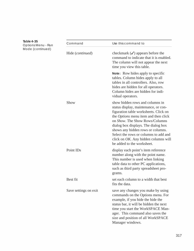
317
Command Use this command to
Hide (continued) checkmark (✓ ) appears before thecommand to indicate that it is enabled.The column will not appear the nexttime you view this table.
Note: Row hides apply to specifictables. Column hides apply to alltables in all controllers. Also, rowhides are hidden for all operators.Column hides are hidden for indi-vidual operators.
Show show hidden rows and columns instatus display, maintenance, or con-figuration table worksheets. Click onthe Options menu item and then clickon Show. The Show Rows/Columnsdialog box displays. The dialog boxshows any hidden rows or columns.Select the rows or columns to add andclick on OK. Any hidden columns willbe added to the worksheet.
Point IDs display each point’s item referencenumber along with the point name.This number is used when linkingtable data to other PC applications,such as third party spreadsheet pro-grams.
Best fit set each column to a width that bestfits the data.
Save settings on exit save any changes you make by usingcommands on the Options menu. Forexample, if you hide the hide thestatus bar, it will be hidden the nexttime you start the WorkSPACE Man-ager. This command also saves thesize and position of all WorkSPACEManager windows.
Table 4-35Options Menu - RunMode (continued)
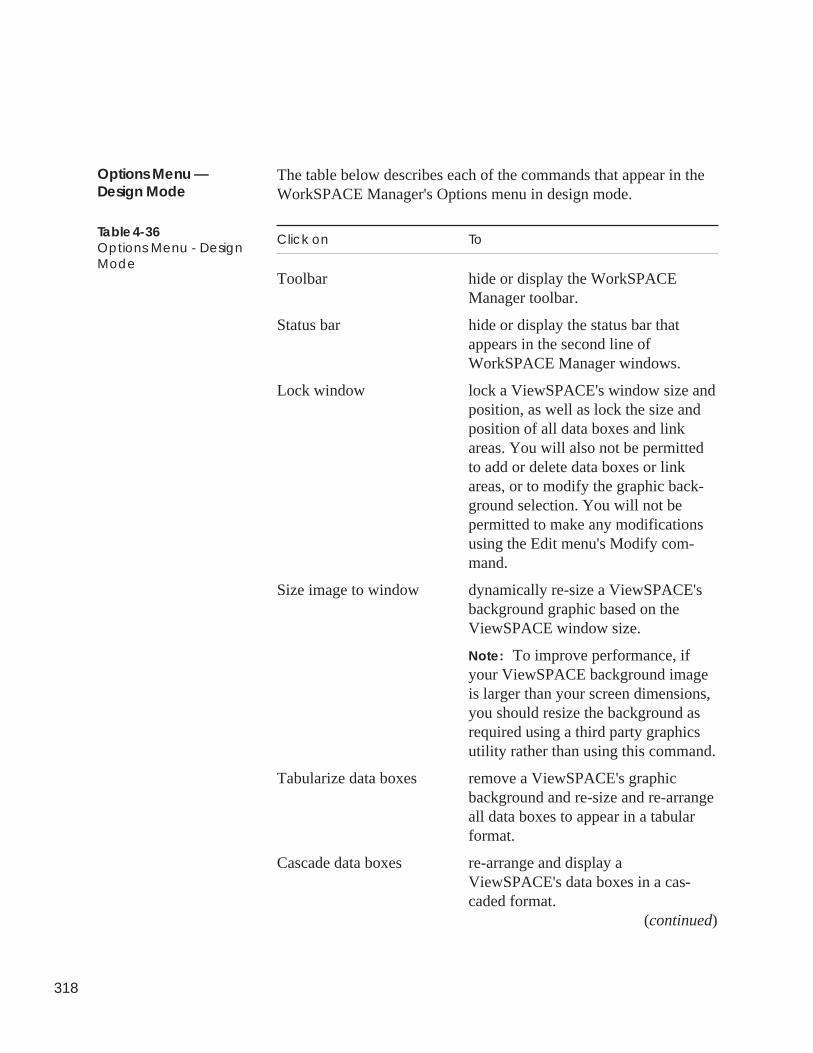
318
The table below describes each of the commands that appear in theWorkSPACE Manager's Options menu in design mode.
Click on To
Toolbar hide or display the WorkSPACEManager toolbar.
Status bar hide or display the status bar thatappears in the second line ofWorkSPACE Manager windows.
Lock window lock a ViewSPACE's window size andposition, as well as lock the size andposition of all data boxes and linkareas. You will also not be permittedto add or delete data boxes or linkareas, or to modify the graphic back-ground selection. You will not bepermitted to make any modificationsusing the Edit menu's Modify com-mand.
Size image to window dynamically re-size a ViewSPACE'sbackground graphic based on theViewSPACE window size.
Note: To improve performance, ifyour ViewSPACE background imageis larger than your screen dimensions,you should resize the background asrequired using a third party graphicsutility rather than using this command.
Tabularize data boxes remove a ViewSPACE's graphicbackground and re-size and re-arrangeall data boxes to appear in a tabularformat.
Cascade data boxes re-arrange and display aViewSPACE's data boxes in a cas-caded format.
(continued)
Options Menu —Design Mode
Table 4-36Options Menu - DesignMode
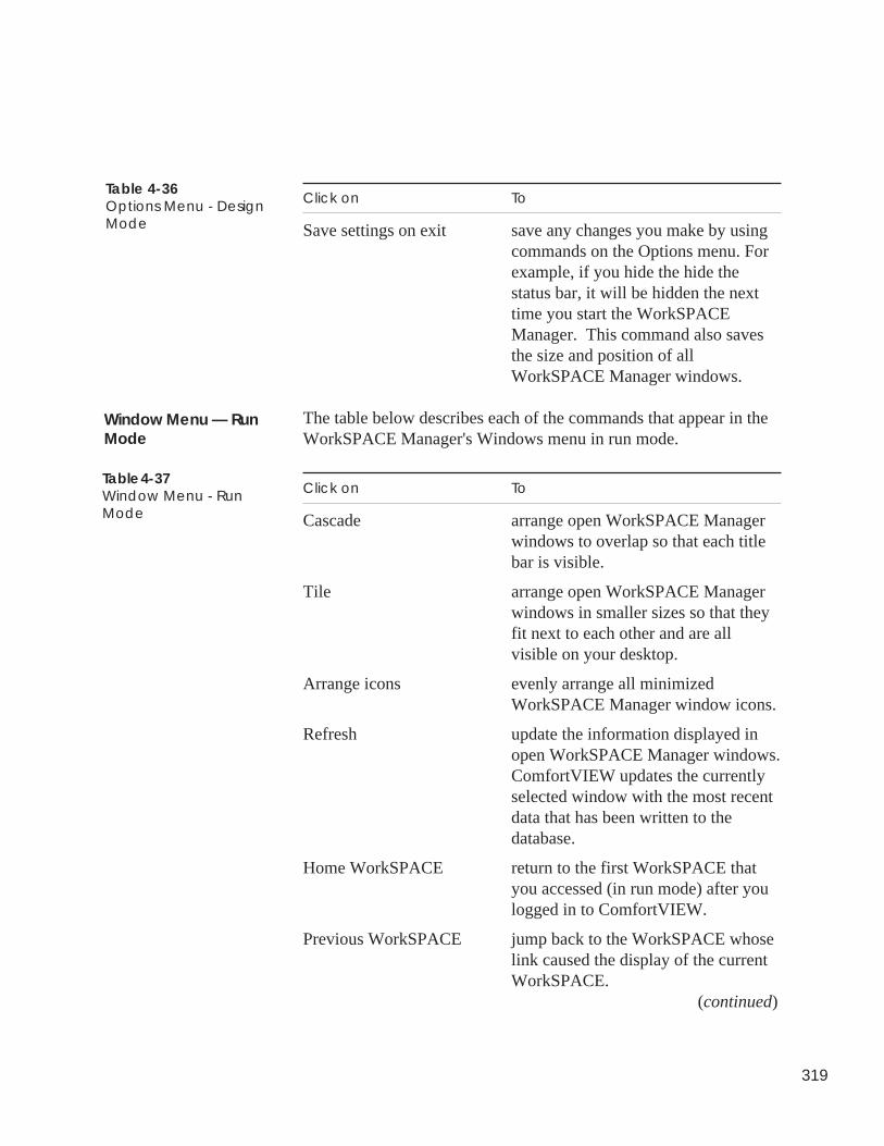
319
Click on To
Save settings on exit save any changes you make by usingcommands on the Options menu. Forexample, if you hide the hide thestatus bar, it will be hidden the nexttime you start the WorkSPACEManager. This command also savesthe size and position of allWorkSPACE Manager windows.
The table below describes each of the commands that appear in theWorkSPACE Manager's Windows menu in run mode.
Click on To
Cascade arrange open WorkSPACE Managerwindows to overlap so that each titlebar is visible.
Tile arrange open WorkSPACE Managerwindows in smaller sizes so that theyfit next to each other and are allvisible on your desktop.
Arrange icons evenly arrange all minimizedWorkSPACE Manager window icons.
Refresh update the information displayed inopen WorkSPACE Manager windows.ComfortVIEW updates the currentlyselected window with the most recentdata that has been written to thedatabase.
Home WorkSPACE return to the first WorkSPACE thatyou accessed (in run mode) after youlogged in to ComfortVIEW.
Previous WorkSPACE jump back to the WorkSPACE whoselink caused the display of the currentWorkSPACE.
(continued)
Table 4-36Options Menu - DesignMode
Window Menu — RunMode
Table 4-37Window Menu - RunMode
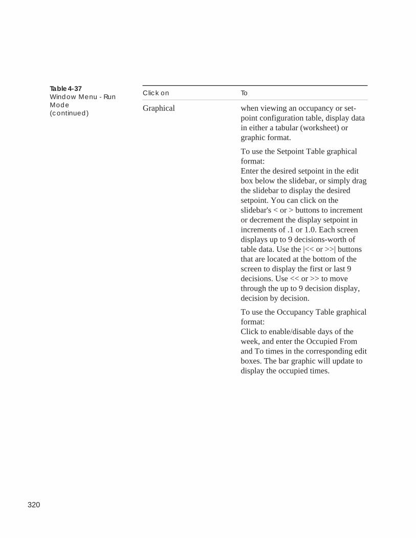
320
Click on To
Graphical when viewing an occupancy or set-point configuration table, display datain either a tabular (worksheet) orgraphic format.
To use the Setpoint Table graphicalformat:Enter the desired setpoint in the editbox below the slidebar, or simply dragthe slidebar to display the desiredsetpoint. You can click on theslidebar's < or > buttons to incrementor decrement the display setpoint inincrements of .1 or 1.0. Each screendisplays up to 9 decisions-worth oftable data. Use the |<< or >>| buttonsthat are located at the bottom of thescreen to display the first or last 9decisions. Use << or >> to movethrough the up to 9 decision display,decision by decision.
To use the Occupancy Table graphicalformat:Click to enable/disable days of theweek, and enter the Occupied Fromand To times in the corresponding editboxes. The bar graphic will update todisplay the occupied times.
Table 4-37Window Menu - RunMode(continued)
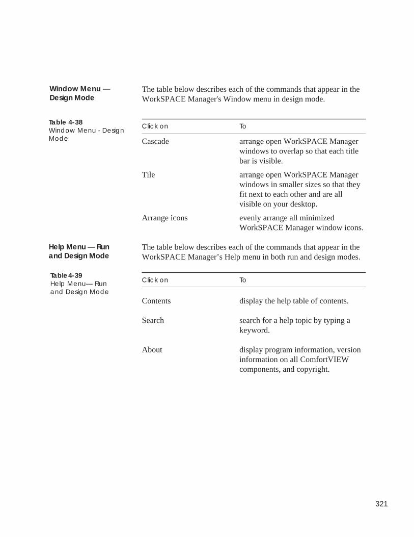
321
The table below describes each of the commands that appear in theWorkSPACE Manager's Window menu in design mode.
Click on To
Cascade arrange open WorkSPACE Managerwindows to overlap so that each titlebar is visible.
Tile arrange open WorkSPACE Managerwindows in smaller sizes so that theyfit next to each other and are allvisible on your desktop.
Arrange icons evenly arrange all minimizedWorkSPACE Manager window icons.
The table below describes each of the commands that appear in theWorkSPACE Manager’s Help menu in both run and design modes.
Click on To
Contents display the help table of contents.
Search search for a help topic by typing akeyword.
About display program information, versioninformation on all ComfortVIEWcomponents, and copyright.
Table 4-39Help Menu— Runand Design Mode
Help Menu — Runand Design Mode
Window Menu —Design Mode
Table 4-38Window Menu - DesignMode

322

Alarm Manager

Alarm Manager
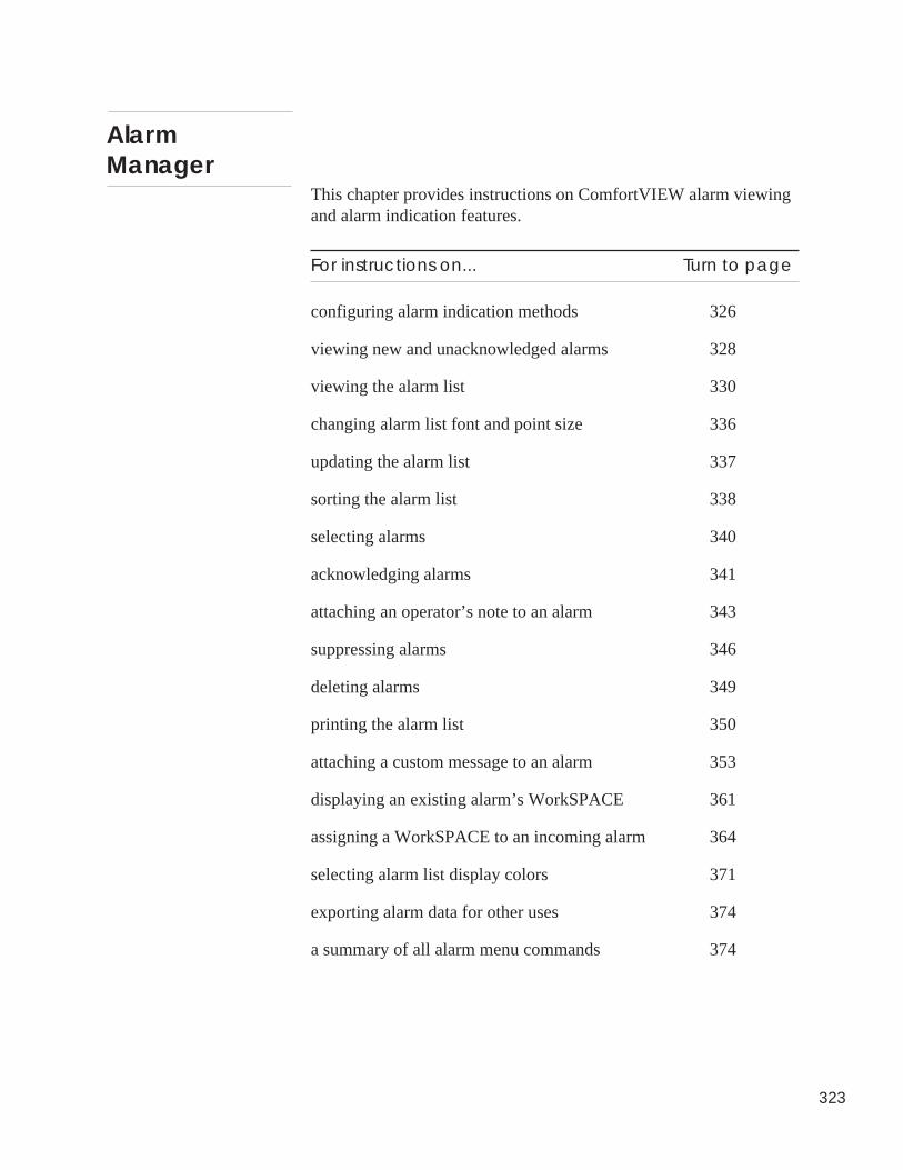
323
This chapter provides instructions on ComfortVIEW alarm viewingand alarm indication features.
For instructions on... Turn to page
configuring alarm indication methods 326
viewing new and unacknowledged alarms 328
viewing the alarm list 330
changing alarm list font and point size 336
updating the alarm list 337
sorting the alarm list 338
selecting alarms 340
acknowledging alarms 341
attaching an operator’s note to an alarm 343
suppressing alarms 346
deleting alarms 349
printing the alarm list 350
attaching a custom message to an alarm 353
displaying an existing alarm’s WorkSPACE 361
assigning a WorkSPACE to an incoming alarm 364
selecting alarm list display colors 371
exporting alarm data for other uses 374
a summary of all alarm menu commands 374
AlarmManager
324
Terminology Alarm — The occurrence of an abnormal condition such as a valueoutside specified limits or a communication failure detected by the NDSModule. Alarms can originate from a CCN system element such as FID,a CCN option, a PIC, an NDS Module, or an Autodial Gateway.
Alert — The occurrence of an abnormal condition such as a value out-side specified limits or a communication failure detected by the NDSModule. Alarms can originate from a CCN system element such as aFID, a CCN Option, a PIC, an NDS Module, or an Autodial Gateway.
Autodial Gateway — A Communications Input/Output (CIO) Modulecontaining software that enables it to communicate by means of a modemover telephone lines with other Autodial Gateway-equipped CCNs.
CCN Option — A Communications Input/Output (CIO) Module thatcontains a special purpose algorithm and accompanying communicationsoftware designed to provide a function for the entire CCN or a desig-nated portion of it.
Comfort Controller — A micro-processor-based control module thatprovides general purpose HVAC control and monitoring capability in astandalone or network environment using closed-loop, direct digitalcontrol. The Comfort Controller can monitor or control up to 64 fieldpoints.
NDS Module — The NDS (Network Directory Services) Module is aCommunications Input/Output (CIO) Module that contains software toenable it to maintain a directory of system elements on the CCN Commu-nication Bus and to perform periodic diagnostic checks on those systemelements.
PIC — A PIC (Product Integrated Control) is an electronic control that isfactory installed on specific Carrier HVAC equipment. PIC controlsprovide standalone operation and can also be connected as a systemelement on the CCN Communication Bus.
WorkSPACE — A group of windows containing graphics (known asViewSPACEs) and trend plots of CCN data. You use the ComfortVIEWWorkSPACE Manager application to create and view WorkSPACEs. Forexample, you could set up a WorkSPACE to include a temperature trendand a graphic of the associated chilled water system. You could thendisplay all of these windows simultaneously.
325
An alarm or alert is the occurrence of an abnormal condition such asa value outside specified limits or a communication failure detectedby the Network Directory Service (NDS) Module. An alarm canoriginate from a CCN system element such as a UT203 FID, aComfort Controller, a CCN option, a PIC, an NDS Module, or anAutodial Gateway.
When a condition arises on the Carrier Comfort Network that causesan alarm or alert, the system element that is in alarm sends a notifi-cation message along the communication bus to ComfortVIEW.ComfortVIEW receives and stores the message in its alarm list, anddepending on how you set up the alarm indication function, pro-duces an audible “beep” , plays a .wav sound file, and displays aflashing alarm symbol on the screen. When the value returns towithin specified limits, the CCN system element generates a return-to-normal message and sends this message to ComfortVIEW.ComfortVIEW receives and stores return-to-normal messages in thesame fashion as it does for alarms and alerts.
Alarms and alerts can be received from remote CCNs using Carrier'sCCN Autodial Gateway, TeLINK, or NAM products.
Alarms and alerts are indicated in the Carrier Network Manager’sCCN displays as well.
ComfortVIEW enables you to:
• view, acknowledge, print, and delete the alarm messages.
• sort the presentation of the alarm list (by alarm level, time/date,or alphabetically by area, zone, element, or point name).
• create custom messages and operator notes for attachment toalarms or groups of alarms.
• suppress the audible and visual indication of “nuisance” alarms.
• assign WorkSPACEs to alarms or groups of alarms.
• filter the indication or display of alarms for a logged on user.
Note: Alarm filtering is done using ComfortVIEW Setupfunction. Refer to the Setup chapter of this manual forinstructions.
Introduction
326
You can configure the manner in which ComfortVIEW notifies youof the existence of new and unacknowledged CCN alarms andalerts. ComfortVIEW can notify you in one of three manners:
• An audible beeping sound occurs or a .wav sound file playswith no visual indication.
You must view the Alarm List to see the alarm or alert. Thealarm/alert is displayed in the list along with all other CCNalarms and alerts.
• A flashing alarm icon displays along with the word alarm, alert,or return to normal and the level (0 to 6).
The level indicates the highest level unacknowledged alarm/alertin the system. The icon displays on top of the current windowand continues to flash until you double click on it and acknowl-edge receipt of the alarm/alert. This option also produces anaudible beep or plays a .wav sound file plays on initial alarmreception. Additional information on this option is in the Flash-ing Icon Alarm Viewing section of this chapter.
• A pop-up window displays on top of the current window.
If you close the window without acknowledging the alarm/alert,it immediately re-displays until you acknowledge receipt of thealarm/alert. This option also produces an audible beep or plays a.wav sound file on initial alarm reception. Additional informa-tion on this option is in the Pop-up Window Alarm Viewingsection of this chapter.
Note: If you are logged out of ComfortVIEW and an alarm/alertoccurs, you are notified in the manner that you haveselected using the Setup application's Log out state com-mand. Refer to the Specifying Operator Alarm IndicationPreferences section of this manual's Setup chapter foradditional information on this command.
Alarm IndicationMethods
327
ComfortVIEW also includes a critical alarm indication feature thatyou can apply to any of these three alarm indication options. If youselect this option, ComfortVIEW displays a full-screen pop-upwindow on top of the current window. ComfortVIEW displays thisfull-screen window when it receives any alarm with an alarm levelthat is less than or equal to the critical alarm threshold value youenter in the Setup application's Alarm Indications Preferences dialogbox. Alarm levels range from 0 to 7, with Level 0 alarms beingmore severe than Level 7 alarms. Functionally, this pop-up windowis the same as the window described in the Pop-up Window AlarmViewing section of this chapter. This window, however, occupiesyour entire screen and its background displays in your selectedWindows highlight color.
Double clicking on the title bar reduces the window and subsequentnon-critical alarm indication windows to the normal pop-up windowsize.
Note: You should do this to prevent future non-critical alarmpop-up windows from occupying the full screen.
You select a form of indication using ComfortVIEW’s Setup appli-cation. For instructions, refer to Specifying Alarm Indication Prefer-ences in the Setup chapter of this manual.
Critical AlarmIndication Option
Specifying Your AlarmIndication Preference
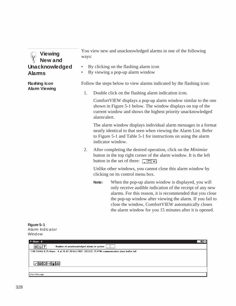
328
You view new and unacknowledged alarms in one of the followingways:
• By clicking on the flashing alarm icon• By viewing a pop-up alarm window
Follow the steps below to view alarms indicated by the flashing icon:
1. Double click on the flashing alarm indication icon.
ComfortVIEW displays a pop-up alarm window similar to the oneshown in Figure 5-1 below. The window displays on top of thecurrent window and shows the highest priority unacknowledgedalarm/alert.
The alarm window displays individual alarm messages in a formatnearly identical to that seen when viewing the Alarm List. Referto Figure 5-1 and Table 5-1 for instructions on using the alarmindicator window.
2. After completing the desired operation, click on the Minimizebutton in the top right corner of the alarm window. It is the leftbutton in the set of three: .
Unlike other windows, you cannot close this alarm window byclicking on its control menu box.
Note: When the pop-up alarm window is displayed, you willonly receive audible indication of the receipt of any newalarms. For this reason, it is recommended that you closethe pop-up window after viewing the alarm. If you fail toclose the window, ComfortVIEW automatically closesthe alarm window for you 15 minutes after it is opened.
ViewingNew and
UnacknowledgedAlarms
Flashing IconAlarm Viewing
Figure 5-1Alarm IndicatorWindow
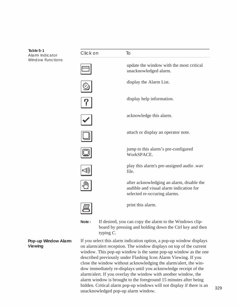
329
Click on To
update the window with the most criticalunacknowledged alarm.
display the Alarm List.
display help information.
acknowledge this alarm.
attach or display an operator note.
jump to this alarm’s pre-configuredWorkSPACE.
play this alarm's pre-assigned audio .wavfile.
after acknowledging an alarm, disable theaudible and visual alarm indication forselected re-occuring alarms.
print this alarm.
Note: If desired, you can copy the alarm to the Windows clip-board by pressing and holding down the Ctrl key and thentyping C.
If you select this alarm indication option, a pop-up window displayson alarm/alert reception. The window displays on top of the currentwindow. This pop-up window is the same pop-up window as the onedescribed previously under Flashing Icon Alarm Viewing. If youclose the window without acknowledging the alarm/alert, the win-dow immediately re-displays until you acknowledge receipt of thealarm/alert. If you overlay the window with another window, thealarm window is brought to the foreground 15 minutes after beinghidden. Critical alarm pop-up windows will not display if there is anunacknowledged pop-up alarm window.
Table 5-1Alarm IndicatorWindow Functions
Pop-up Window AlarmViewing
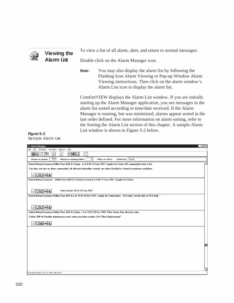
330
Viewing theAlarm List
Figure 5-2Sample Alarm List
To view a list of all alarm, alert, and return to normal messages:
Double click on the Alarm Manager icon.
Note: You may also display the alarm list by following theFlashing Icon Alarm Viewing or Pop-up Window AlarmViewing instructions. Then click on the alarm window’sAlarm List icon to display the alarm list.
ComfortVIEW displays the Alarm List window. If you are initiallystarting up the Alarm Manager application, you see messages in thealarm list sorted according to time/date received. If the AlarmManager is running, but was minimized, alarms appear sorted in thelast order defined. For more information on alarm sorting, refer tothe Sorting the Alarm List section of this chapter. A sample AlarmList window is shown in Figure 5-2 below.
331
The Alarm Menu The top line of the Alarm List window contains the alarm menu.This menu contains the alarm viewing commands that allow you toperform functions such as acknowledging, sorting, and deletingalarms. The Alarm Menu Commands section of this chapter de-scribes each of the commands that appear in the alarm menu.
The second line of the Alarm List window contains a toolbar. Thetoolbar gives you instant access to the most frequently used alarmviewing commands. By simply clicking the mouse button, you canprint, delete, or acknowledge alarms, update the alarm list, select orde-select all alarms, or display on-line help.
Note: If desired, you can remove the toolbar from the windowby clicking on the Options menu item and then clicking onToolbar. To return the toolbar to the window, performthese two commands again.
The bottom line of each individual alarm message contains analarm-specific toolbar. By clicking the mouse on one of the tools inthis toolbar, you can acknowledge this individual alarm, display ormodify this alarm’s operator note, or invoke the WorkSPACEManager and view this alarm’s assigned WorkSPACE.
The following table describes the buttons that appear on the alarmlist and alarm-specific toolbars.
The Toolbars
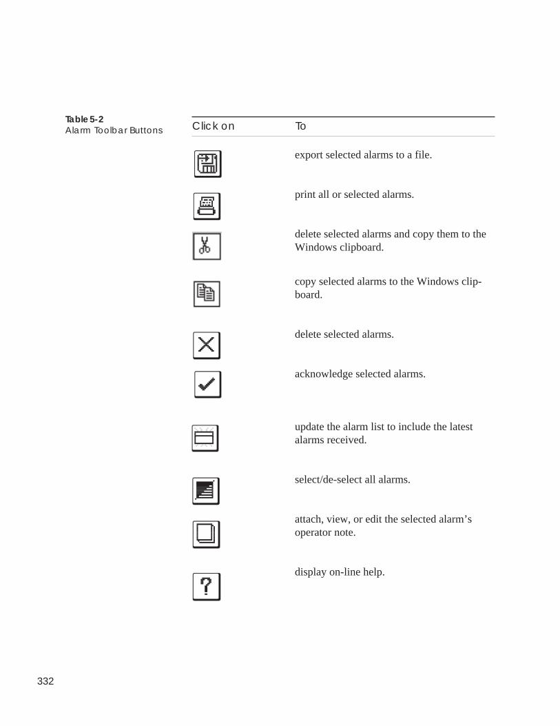
332
Table 5-2Alarm Toolbar Buttons Click on To
export selected alarms to a file.
print all or selected alarms.
delete selected alarms and copy them to theWindows clipboard.
copy selected alarms to the Windows clip-board.
delete selected alarms.
acknowledge selected alarms.
update the alarm list to include the latestalarms received.
select/de-select all alarms.
attach, view, or edit the selected alarm’soperator note.
display on-line help.
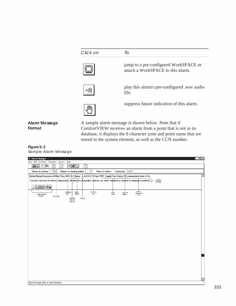
333
Click on To
jump to a pre-configured WorkSPACE orattach a WorkSPACE to this alarm.
play this alarm's pre-configured .wav audiofile.
suppress future indication of this alarm.
A sample alarm message is shown below. Note that ifComfortVIEW receives an alarm from a point that is not in itsdatabase, it displays the 8 character zone and point name that arestored in the system element, as well as the CCN number.
Figure 5-3Sample Alarm Message
Alarm MessageFormat
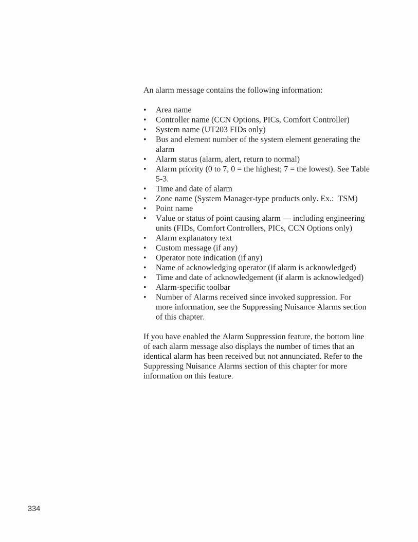
334
An alarm message contains the following information:
• Area name• Controller name (CCN Options, PICs, Comfort Controller)• System name (UT203 FIDs only)• Bus and element number of the system element generating the
alarm• Alarm status (alarm, alert, return to normal)• Alarm priority (0 to 7, 0 = the highest; 7 = the lowest). See Table
5-3.• Time and date of alarm• Zone name (System Manager-type products only. Ex.: TSM)• Point name• Value or status of point causing alarm — including engineering
units (FIDs, Comfort Controllers, PICs, CCN Options only)• Alarm explanatory text• Custom message (if any)• Operator note indication (if any)• Name of acknowledging operator (if alarm is acknowledged)• Time and date of acknowledgement (if alarm is acknowledged)• Alarm-specific toolbar• Number of Alarms received since invoked suppression. For
more information, see the Suppressing Nuisance Alarms sectionof this chapter.
If you have enabled the Alarm Suppression feature, the bottom lineof each alarm message also displays the number of times that anidentical alarm has been received but not annunciated. Refer to theSuppressing Nuisance Alarms section of this chapter for moreinformation on this feature.
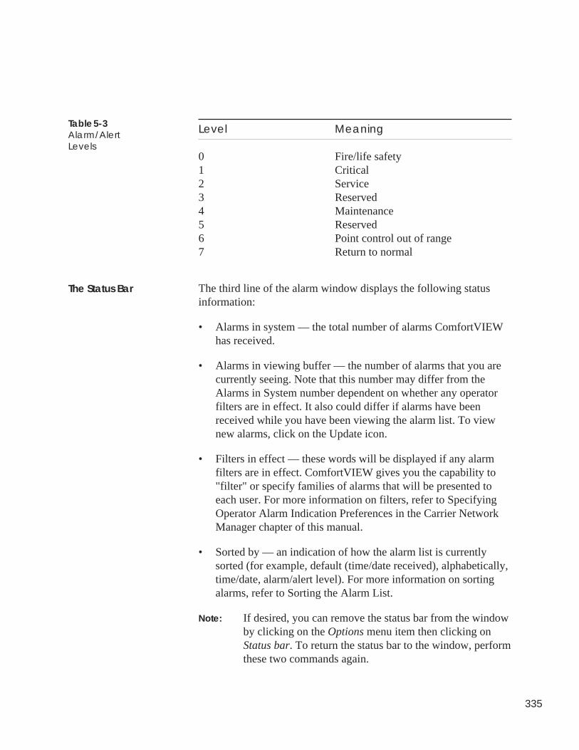
335
Level Meaning
0 Fire/life safety1 Critical2 Service3 Reserved4 Maintenance5 Reserved6 Point control out of range7 Return to normal
The third line of the alarm window displays the following statusinformation:
• Alarms in system — the total number of alarms ComfortVIEWhas received.
• Alarms in viewing buffer — the number of alarms that you arecurrently seeing. Note that this number may differ from theAlarms in System number dependent on whether any operatorfilters are in effect. It also could differ if alarms have beenreceived while you have been viewing the alarm list. To viewnew alarms, click on the Update icon.
• Filters in effect — these words will be displayed if any alarmfilters are in effect. ComfortVIEW gives you the capability to"filter" or specify families of alarms that will be presented toeach user. For more information on filters, refer to SpecifyingOperator Alarm Indication Preferences in the Carrier NetworkManager chapter of this manual.
• Sorted by — an indication of how the alarm list is currentlysorted (for example, default (time/date received), alphabetically,time/date, alarm/alert level). For more information on sortingalarms, refer to Sorting the Alarm List.
Note: If desired, you can remove the status bar from the windowby clicking on the Options menu item then clicking onStatus bar. To return the status bar to the window, performthese two commands again.
Table 5-3Alarm/AlertLevels
The Status Bar
336
You can change the font that ComfortVIEW uses to display alarmlist text. When you change the font, all alarm list text is affected.
To change the font:
1. Display the alarm list. If necessary, refer to the instructionslisted under Viewing the Alarm List.
2. Click on the Options menu item and then click on Fonts.
ComfortVIEW displays the Font dialog box. Refer to Figure5-4.
3. In the Font box, select the font to use.
The text in the Sample box changes to reflect the font youselect.
4. In the Font Style box, select any style options to use (forexample, bold or italic).
5. In the Size box, select the point size to use: the larger thepoint size, the larger the characters appear on your screen.
6. Click on OK.
All alarm list text displays in the new font.
Note: To make the font change permanent, click on the Optionsmenu item and then click on Save settings on exit. Acheckmark (✓ ) appears before the command to indicate thatit is enabled. The text will appear in the new font, style, andpoint size the next time you display the alarm list.
Changing the Font
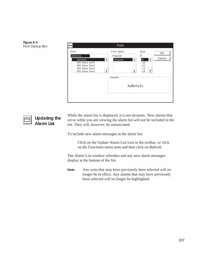
337
Figure 5-4Font Dialog Box
8
8
Font:
Font
Sample
Font Style: Size:
GenevaMS Sans SerifMS Sans SerifMS Sans SerifMS Sans Serif
Regular
Regular10121418
AaBbYyZz
GenevaOK
Cancel
While the alarm list is displayed, it is not dynamic. New alarms thatoccur while you are viewing the alarm list will not be included in thelist. They will, however, be annunciated.
To include new alarm messages in the alarm list:
Click on the Update Alarm List icon in the toolbar, or clickon the Functions menu item and then click on Refresh.
The Alarm List window refreshes and any new alarm messagesdisplay at the bottom of the list.
Note: Any sorts that may have previously been selected will nolonger be in effect. Any alarms that may have previouslybeen selected will no longer be highlighted.
Updating theAlarm List
338
You can sort the presentation of the alarm list:
• alphabetically by area, zone, element, or point name• by alarm/alert level from zero down to six followed by return to
normals.• chronologically by time/date (beginning with those alarms that
occurred earliest.)
You can use sorts in combination with each other. The last sortchosen will have precedence. For example, if you select Area,Alarm level, then Time/Date, ComfortVIEW sorts the file firstaccording to time/date, then by alarm level, and then alphabeticallyby area name.
To sort the alarm list:
1. Display the alarm list. If necessary, follow the instructionslisted under Viewing the Alarm List.
2. Click on the Options menu item and then click on Sort.
ComfortVIEW displays the sorts list. The sorts that arecurrently active are indicated with a checkmark.
3. Click on one or more of the following menu items: Default,Time/Date, Area, Zone, Element, Point, or Alarm Level.
Note: Clicking on an active sort de-selects it.
Clicking on Default removes all sorts currently ineffect and sorts alarms by time and date of receptionbeginning with those alarms received earliest.
The alarm list updates and re-displays, sorted accordingly.An indication of the currently-selected sorts displays in thestatus bar, which displays on the third line of the alarm listwindow.
Figure 5-5 shows an alarm list sorted by time and date.
Sorting theAlarm List
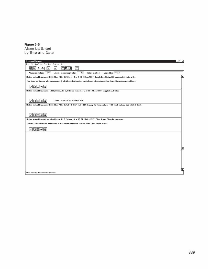
339
Figure 5-5Alarm List Sortedby Time and Date
340
Some of ComfortVIEW alarms operations require you to selectalarm/alert/return to normal messages. For example, you mustspecify which alarms you wish to print or delete. You can selectone, more than one, or all alarm messages.
To select one or more alarm messages:
1. Display the alarm list.
For instructions, turn to Viewing the Alarm List.
2. Click on the alarm message or messages you wish to select.
When you select an alarm message, its background becomeshighlighted with the highlight color that you have selected inyour Windows control panel. This indicates that a message is“selected.” Clicking on a “selected” alarm message un-highlights the background and “de-selects” the message.
Note: When in the alarm list, you can select multiple alarmsusing the standard Windows Ctrl-Click or Shift-Clicktechnique.
To select all alarm messages:
1. Display the alarm list. If necessary, follow the instructionslisted under Viewing the Alarm List.
2. Click on the toolbar’s Select All icon, or click on Functionsthen click on Select all.
The background of all alarm messages becomes highlightedwith the highlight color that you have selected in your Win-dows control panel. This indicates that a message is “se-lected.” Clicking on a “selected” alarm message un-high-lights the background and “de-selects” the message.
SelectingAlarms
Selecting One or MoreMessages
Selecting AllMessages
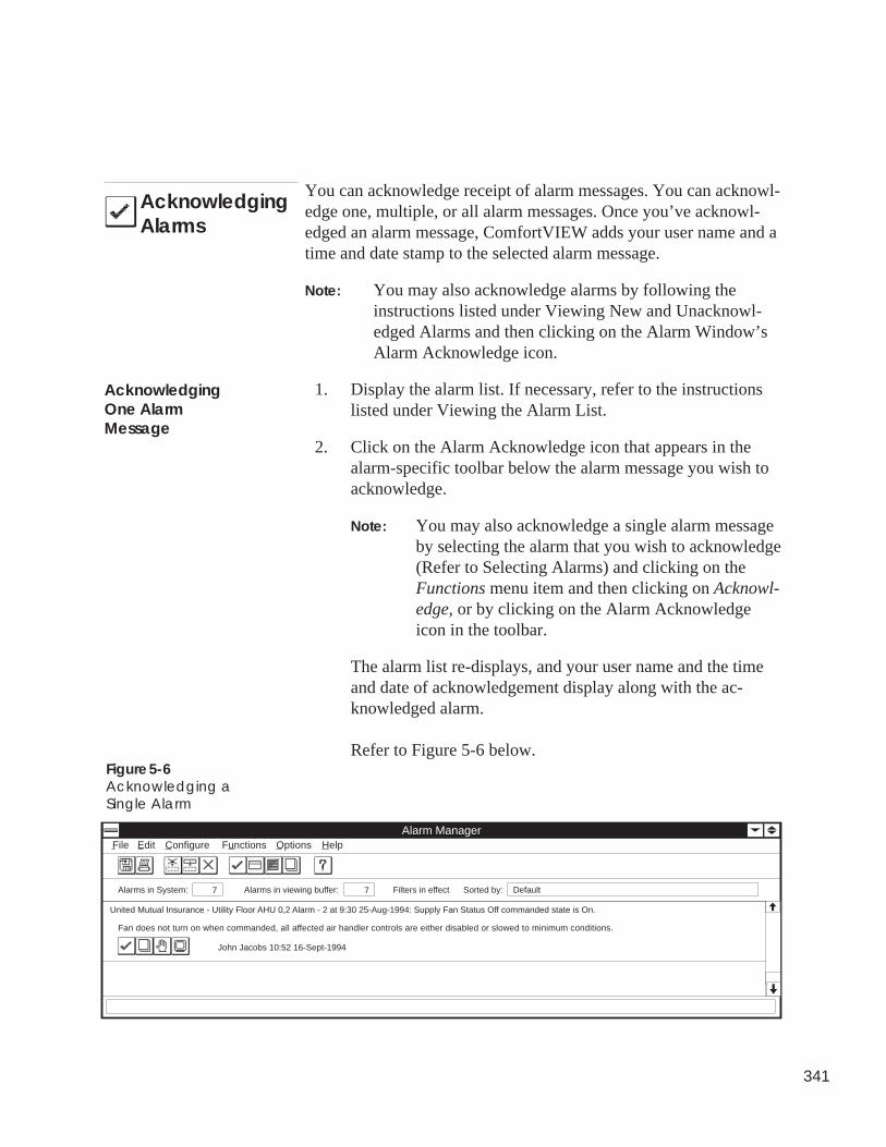
341
AcknowledgingAlarms
You can acknowledge receipt of alarm messages. You can acknowl-edge one, multiple, or all alarm messages. Once you’ve acknowl-edged an alarm message, ComfortVIEW adds your user name and atime and date stamp to the selected alarm message.
Note: You may also acknowledge alarms by following theinstructions listed under Viewing New and Unacknowl-edged Alarms and then clicking on the Alarm Window’sAlarm Acknowledge icon.
1. Display the alarm list. If necessary, refer to the instructionslisted under Viewing the Alarm List.
2. Click on the Alarm Acknowledge icon that appears in thealarm-specific toolbar below the alarm message you wish toacknowledge.
Note: You may also acknowledge a single alarm messageby selecting the alarm that you wish to acknowledge(Refer to Selecting Alarms) and clicking on theFunctions menu item and then clicking on Acknowl-edge, or by clicking on the Alarm Acknowledgeicon in the toolbar.
The alarm list re-displays, and your user name and the timeand date of acknowledgement display along with the ac-knowledged alarm.
Refer to Figure 5-6 below.
Fan does not turn on when commanded, all affected air handler controls are either disabled or slowed to minimum conditions.
Alarms in System: 7 Alarms in viewing buffer: 7
United Mutual Insurance - Utility Floor AHU 0,2 Alarm - 2 at 9:30 25-Aug-1994: Supply Fan Status Off commanded state is On.
Alarm Manager
Sorted by: Default
File Edit Configure Functions Options Help
Filters in effect
John Jacobs 10:52 16-Sept-1994
Figure 5-6Acknowledging aSingle Alarm
AcknowledgingOne AlarmMessage
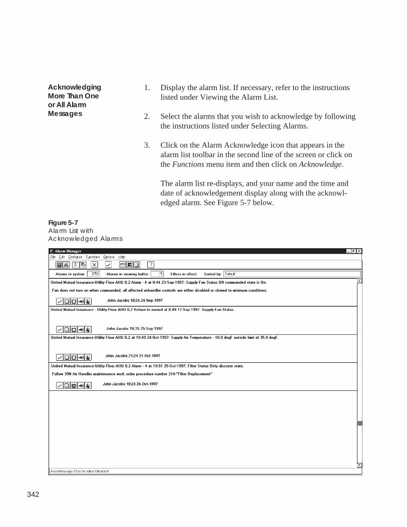
342
AcknowledgingMore Than Oneor All AlarmMessages
Figure 5-7Alarm List withAcknowledged Alarms
1. Display the alarm list. If necessary, refer to the instructionslisted under Viewing the Alarm List.
2. Select the alarms that you wish to acknowledge by followingthe instructions listed under Selecting Alarms.
3. Click on the Alarm Acknowledge icon that appears in thealarm list toolbar in the second line of the screen or click onthe Functions menu item and then click on Acknowledge.
The alarm list re-displays, and your name and the time anddate of acknowledgement display along with the acknowl-edged alarm. See Figure 5-7 below.
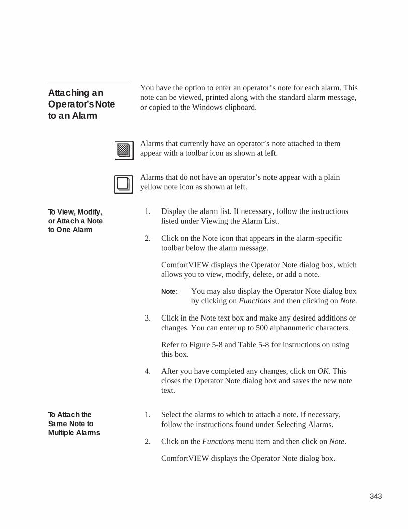
343
You have the option to enter an operator’s note for each alarm. Thisnote can be viewed, printed along with the standard alarm message,or copied to the Windows clipboard.
Alarms that currently have an operator’s note attached to themappear with a toolbar icon as shown at left.
Alarms that do not have an operator’s note appear with a plainyellow note icon as shown at left.
1. Display the alarm list. If necessary, follow the instructionslisted under Viewing the Alarm List.
2. Click on the Note icon that appears in the alarm-specifictoolbar below the alarm message.
ComfortVIEW displays the Operator Note dialog box, whichallows you to view, modify, delete, or add a note.
Note: You may also display the Operator Note dialog boxby clicking on Functions and then clicking on Note.
3. Click in the Note text box and make any desired additions orchanges. You can enter up to 500 alphanumeric characters.
Refer to Figure 5-8 and Table 5-8 for instructions on usingthis box.
4. After you have completed any changes, click on OK. Thiscloses the Operator Note dialog box and saves the new notetext.
1. Select the alarms to which to attach a note. If necessary,follow the instructions found under Selecting Alarms.
2. Click on the Functions menu item and then click on Note.
ComfortVIEW displays the Operator Note dialog box.
To Attach theSame Note toMultiple Alarms
To View, Modify,or Attach a Noteto One Alarm
Attaching anOperator’s Noteto an Alarm
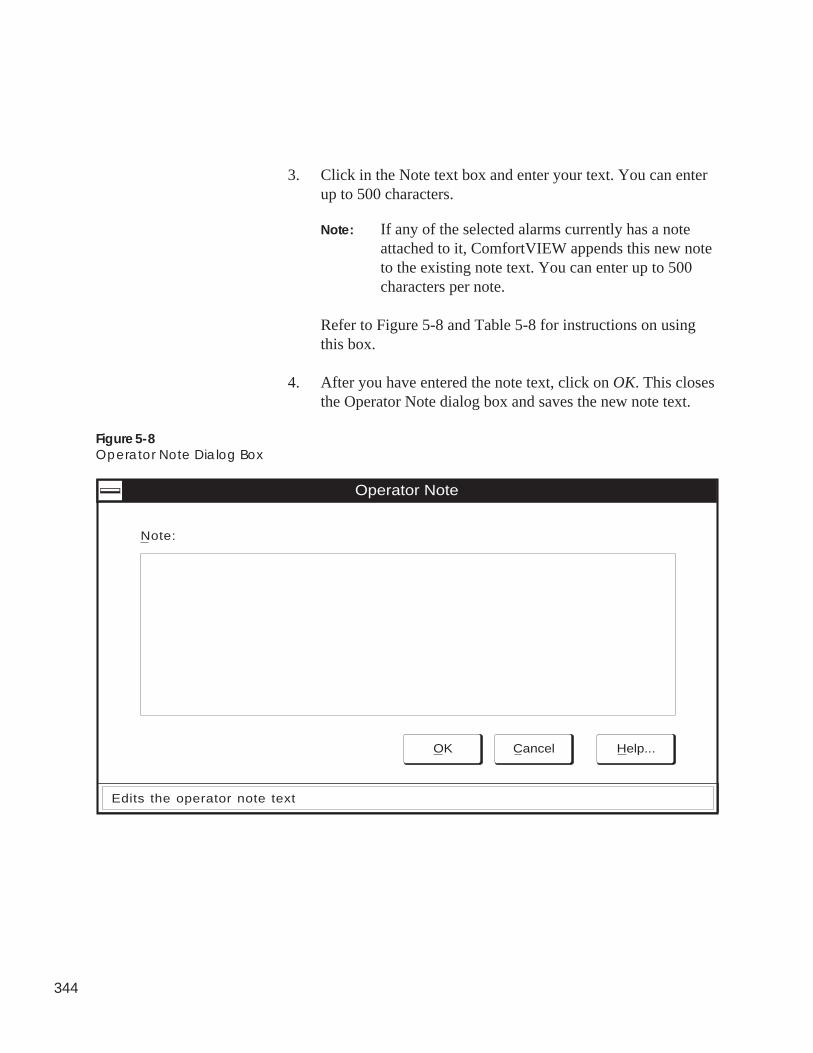
344
Figure 5-8Operator Note Dialog Box
Operator Note
OK Cancel Help...
Note:
Edits the operator note text
3. Click in the Note text box and enter your text. You can enterup to 500 characters.
Note: If any of the selected alarms currently has a noteattached to it, ComfortVIEW appends this new noteto the existing note text. You can enter up to 500characters per note.
Refer to Figure 5-8 and Table 5-8 for instructions on usingthis box.
4. After you have entered the note text, click on OK. This closesthe Operator Note dialog box and saves the new note text.
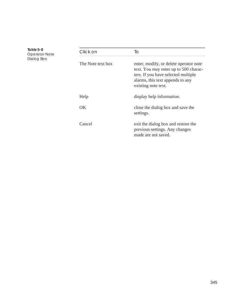
345
Click on To
The Note text box enter, modify, or delete operator notetext. You may enter up to 500 charac-ters. If you have selected multiplealarms, this text appends to anyexisting note text.
Help display help information.
OK close the dialog box and save thesettings.
Cancel exit the dialog box and restore theprevious settings. Any changesmade are not saved.
Table 5-8Operator NoteDialog Box
346
ComfortVIEW alarm suppression feature gives you the capability todisable the audible and visual alarm indication for selected re-occurring alarms. This feature can be useful for “nuisance-type”alarms for which you do not want re-indication upon each subse-quent receipt.
Note: You can only suppress acknowledged alarms.
When ComfortVIEW initially receives an alarm, it stores the alarmin the alarm list, produces an audible signal and, depending on thealarm indication option you select, produces an accompanyingvisual signal. If you enabled alarm suppression, and ComfortVIEWreceives this same alarm again, audible (and visual, if selected)indication does not occur. ComfortVIEW displays the number ofsubsequent receipts of the alarm that has been suppressed in theSuppressed field, which appears in the alarm-specific toolbar belowthe alarm message.
1. Display the alarm list. If necessary, refer to the instructionslisted under Viewing the Alarm List.
2. Acknowledge the alarm that you wish to suppress (if notalready acknowledged).
3. Click on the Suppression icon in the alarm-specific toolbarbelow the alarm whose re-occurrences you wish to suppress.ComfortVIEW displays the Alarm Suppression dialog box.
Note: If the icon appears dimmed, the alarm has not beenacknowledged. You must first acknowledge thealarm before you can suppress it. Refer to Acknowl-edging Alarms.
4. Click on Allow to disable alarm suppression, or click onSuppress to enable alarm suppression.
5. Indicate the suppression duration (in hours) and click on OK.
Refer to Figure 5-9 and Table 5-9 that follow for furtherinstructions on using this dialog box.
SuppressingAlarms
To Enable or DisableAlarm Suppression
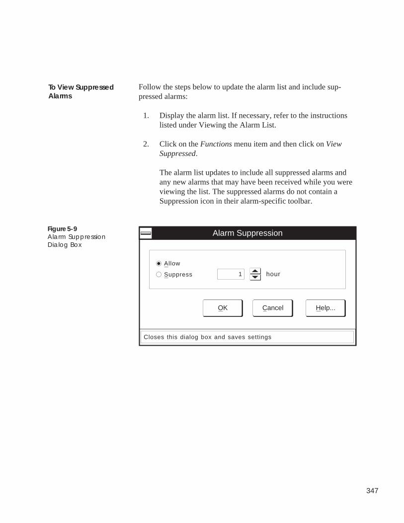
347
Follow the steps below to update the alarm list and include sup-pressed alarms:
1. Display the alarm list. If necessary, refer to the instructionslisted under Viewing the Alarm List.
2. Click on the Functions menu item and then click on ViewSuppressed.
The alarm list updates to include all suppressed alarms andany new alarms that may have been received while you wereviewing the list. The suppressed alarms do not contain aSuppression icon in their alarm-specific toolbar.
To View SuppressedAlarms
Closes this dialog box and saves settings
Alarm Suppression
OK Cancel Help...
hour
Allow
Suppress 1
Figure 5-9Alarm SuppressionDialog Box
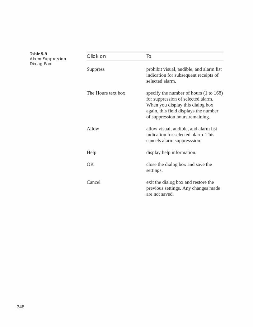
348
Table 5-9Alarm SuppressionDialog Box
Click on To
Suppress prohibit visual, audible, and alarm listindication for subsequent receipts ofselected alarm.
The Hours text box specify the number of hours (1 to 168)for suppression of selected alarm.When you display this dialog boxagain, this field displays the numberof suppression hours remaining.
Allow allow visual, audible, and alarm listindication for selected alarm. Thiscancels alarm suppresssion.
Help display help information.
OK close the dialog box and save thesettings.
Cancel exit the dialog box and restore theprevious settings. Any changes madeare not saved.
349
You can delete all or selected alarms from the alarm list to removeany unnecessary alarms. For example, you should remove an alarmthat was generated during preventive maintenance that may reflect afalse condition. You can only remove acknowledged alarms.
Note: You can also delete alarms using the Cut command, whichappears under the Edit menu item. This command differsfrom the Edit Menu’s Delete command, in that it copiesalarms to the Windows clipboard before deleting them.This could be useful, for example, if you wish to usealarms in a report that you are creating using anotherWindows application.
To delete an alarm:
1. Display the alarm list. If necessary, follow the instructionslisted under Viewing the Alarm List.
2. Select the alarm message or messages you wish to delete byclicking on them. The background of a selected message ishighlighted. This indicates that a message is “selected.” Foradditional information, refer to the Selecting Alarms sectionof this chapter.
3. Click on the Edit menu item and then click on Delete.
Note: You may also perform this command by clicking onthe Delete icon in the toolbar.
ComfortVIEW displays a dialog box asking for confirmationbefore actually deleting any messages.
4. Click on Yes to cause the removal to take place, or click onNo to prevent the removal from taking place.
DeletingAlarms
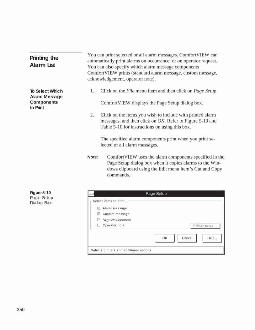
350
You can print selected or all alarm messages. ComfortVIEW canautomatically print alarms on occurrence, or on operator request.You can also specify which alarm message componentsComfortVIEW prints (standard alarm message, custom message,acknowledgement, operator note).
1. Click on the File menu item and then click on Page Setup.
ComfortVIEW displays the Page Setup dialog box.
2. Click on the items you wish to include with printed alarmmessages, and then click on OK. Refer to Figure 5-10 andTable 5-10 for instructions on using this box.
The specified alarm components print when you print se-lected or all alarm messages.
Note: ComfortVIEW uses the alarm components specified in thePage Setup dialog box when it copies alarms to the Win-dows clipboard using the Edit menu item’s Cut and Copycommands.
Printing theAlarm List
To Select WhichAlarm MessageComponentsto Print
Figure 5-10Page SetupDialog Box
Printer setup...
Page Setup
Select items to print...
OK Cancel Help...
Selects printers and additional options
Alarm message
X
Custom message
X
Acknowledgement
X
Operator note
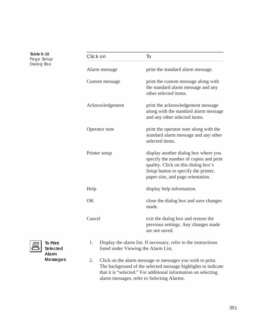
351
Table 5-10Page SetupDialog Box
Click on To
Alarm message print the standard alarm message.
Custom message print the custom message along withthe standard alarm message and anyother selected items.
Acknowledgement print the acknowledgement messagealong with the standard alarm messageand any other selected items.
Operator note print the operator note along with thestandard alarm message and any otherselected items.
Printer setup display another dialog box where youspecify the number of copies and printquality. Click on this dialog box’sSetup button to specify the printer,paper size, and page orientation.
Help display help information.
OK close the dialog box and save changesmade.
Cancel exit the dialog box and restore theprevious settings. Any changes madeare not saved.
1. Display the alarm list. If necessary, refer to the instructionslisted under Viewing the Alarm List.
2. Click on the alarm message or messages you wish to print.The background of the selected message highlights to indicatethat it is “selected.” For additional information on selectingalarm messages, refer to Selecting Alarms.
To PrintSelectedAlarmMessages
352
3. Click on the File menu item and then click on Print.
Note: You may also print the selected alarms by clickingon the toolbar’s Print icon.
ComfortVIEW displays a dialog box asking for confirmationbefore printing.
4. Click on Yes to print the messages, or click on No to preventprinting from taking place.
ComfortVIEW prints the selected alarm messages. The alarmmessage components to be included (alarm message, custom mes-sage, acknowledgement, operator note) are those that you specifyusing the File menu’s Page Setup command.
1. Display the alarm list. If necessary, follow the instructionslisted under Viewing the Alarm List.
2. Click on the File menu item and then click on Print.
Note: You may also print all alarms by clicking on thetoolbar’s Print icon.
ComfortVIEW displays a dialog box asking for confirmationbefore printing.
3. Click on Yes to print the messages, or click on No to preventprinting from taking place.
ComfortVIEW prints all alarm messages. The alarm messagecomponents to be included (alarm message, custom message,acknowledgement, operator note) are those that you specify usingthe File menu’s Page Setup command.
You can set up ComfortVIEW to print alarm messages on occur-rence. You do this using ComfortVIEW's Setup function. Refer tothe Setup chapter of this manual for instructions.
To AutomaticallyPrint Alarms onOccurrence
To Print All AlarmMessages
353
You can add a custom alarm message to the ComfortVIEW customalarm message list and set the criteria for attaching it to incomingalarms. Custom alarm messages can provide additional information,geared to a specific alarm, that ComfortVIEW displays or printsalong with a standard alarm message.
You can also use the custom alarm message interface such thatComfortVIEW will override a specific alarm's default audibleindication and instead play a user-specified .wav sound file onreception of specific alarms.
You set criteria (Area, Zone, Element, Point, and Precedence) forattaching custom messages to incoming alarms. ComfortVIEWcompares incoming alarms to your specified criteria and establishesalarm-custom message links using the following rules:
ComfortVIEW begins by identifying criteria that might qualify themessage for attachment. One possibility that will qualify a custommessage for attachment to an alarm is an exact match between youruser-defined criteria and the incoming alarm. Other possibilitiesinvolve any wildcards that you use to specify criteria. An incomingalarm must satisfy each of the six user-defined criteria before thecustom message can qualify for attachment to the incoming alarm. IfComfortVIEW does not find any set of criteria that qualify forattachment, then the alarm will not have a custom message attached.
For example, you may have one generic custom message that isconfigured for attachment to every air handler alarm, and anothercustom message that is configured for attachment to air handler fanstatus alarms specifically. To ensure that the fan status custommessage gets attached to the air handler fan status alarms, youshould assign a higher precedence to the fan status custom messagethan to the generic air handler custom message. You would assignthe fan status custom message a precedence of Very High, and theair handler message a precedence of Medium. If more than onecustom message qualifies for attachment, ComfortVIEW uses theone with the highest user-specified precedence.
Assigning CustomMessages toIncoming Alarms
Rules for CustomMessage Attachment
354
Adding, Modifying, orDeleting a CustomMessage
Follow the steps below to add, modify, or delete a custom message:
1. Display the alarm list. If necessary, refer to the instructionslisted under Viewing the Alarm List.
2. Click on Configure then click on Custom messages.
ComfortVIEW displays the Assign Custom Alarm Messagesdialog box. This dialog box allows you to add, modify, ordelete a custom alarm message. It also enables you to identifythe criteria for those incoming alarms to which you want thecustom alarm message attached.
The existing messages appear in the box below Select aCustom Alarm Message. As you scroll down the list andhighlight each message, you can see its associated Area,Zone, Element, Level, Point, and Precedence on the bottom ofthe window.
3. Do one of the following, depending on whether you want toadd, modify, or delete a message:
• Click on Add to add a new custom alarm message to thelist of messages, or
• Select a message and then click on Modify to change themessage or its associated incoming alarm criteria, or
• Select a message and then click on Delete to delete it.
4. Refer to Figure 5-11 and Table 5-11 for further instructionson using the fields in this dialog box. Use the Tab or Enterkey to move between fields.
5. Once you have made your changes click on OK. This perma-nently saves the change and closes the Assign Custom AlarmMessages dialog box.
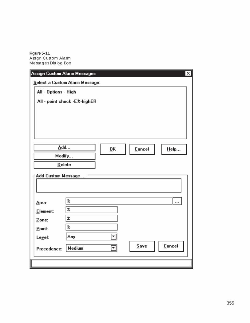
355
Figure 5-11Assign Custom AlarmMessages Dialog Box
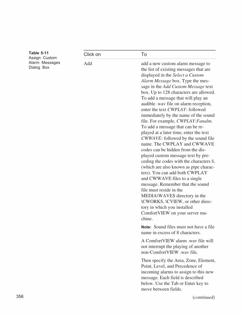
356
Click on To
Add add a new custom alarm message tothe list of existing messages that aredisplayed in the Select a CustomAlarm Message box. Type the mes-sage in the Add Custom Message textbox. Up to 128 characters are allowed.To add a message that will play anaudible .wav file on alarm reception,enter the text CWPLAY: followedimmediately by the name of the soundfile. For example, CWPLAY:Fanalm.To add a message that can be re-played at a later time, enter the textCWWAVE: followed by the sound filename. The CWPLAY and CWWAVEcodes can be hidden from the dis-played custom message text by pre-ceding the codes with the characters ||,(which are also known as pipe charac-ters). You can add both CWPLAYand CWWAVE files to a singlemessage. Remember that the soundfile must reside in theMEDIA\WAVES directory in the\CWORKS, \CVIEW, or other direc-tory in which you installedComfortVIEW on your server ma-chine.
Note: Sound files must not have a filename in excess of 8 characters.
A ComfortVIEW alarm .wav file willnot interrupt the playing of anothernon-ComfortVIEW .wav file.
Then specify the Area, Zone, Element,Point, Level, and Precedence ofincoming alarms to assign to this newmessage. Each field is describedbelow. Use the Tab or Enter key tomove between fields.
(continued)
Table 5-11
Assign Custom
Alarm Messages
Dialog Box
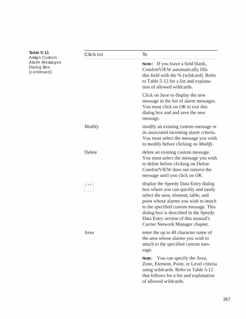
357
Table 5-11Assign CustomAlarm MessagesDialog Box(continued)
Click on To
Note: If you leave a field blank,ComfortVIEW automatically fillsthis field with the % (wildcard). Referto Table 5-12 for a list and explana-tion of allowed wildcards.
Click on Save to display the newmessage in the list of alarm messages.You must click on OK to exit thisdialog box and and save the newmessage.
Modify modify an existing custom message orits associated incoming alarm criteria.You must select the message you wishto modify before clicking on Modify.
Delete delete an existing custom message.You must select the message you wishto delete before clicking on Delete.ComfortVIEW does not remove themessage until you click on OK.
. . . display the Speedy Data Entry dialogbox where you can quickly and easilyselect the area, element, table, andpoint whose alarms you wish to attachto the specified custom message. Thisdialog box is described in the SpeedyData Entry section of this manual'sCarrier Network Manager chapter.
Area enter the up to 48 character name ofthe area whose alarms you wish toattach to the specified custom mes-sage.
Note: You can specify the Area,Zone, Element, Point, or Level criteriausing wildcards. Refer to Table 5-12that follows for a list and explanationof allowed wildcards.
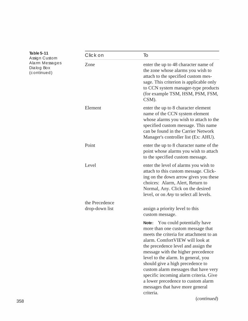
358
Table 5-11Assign CustomAlarm MessagesDialog Box(continued)
Click on To
Zone enter the up to 48 character name ofthe zone whose alarms you wish toattach to the specified custom mes-sage. This criterion is applicable onlyto CCN system manager-type products(for example TSM, HSM, PSM, FSM,CSM).
Element enter the up to 8 character elementname of the CCN system elementwhose alarms you wish to attach to thespecified custom message. This namecan be found in the Carrier NetworkManager's controller list (Ex: AHU).
Point enter the up to 8 character name of thepoint whose alarms you wish to attachto the specified custom message.
Level enter the level of alarms you wish toattach to this custom message. Click-ing on the down arrow gives you thesechoices: Alarm, Alert, Return toNormal, Any. Click on the desiredlevel, or on Any to select all levels.
the Precedencedrop-down list assign a priority level to this
custom message.
Note: You could potentially havemore than one custom message thatmeets the criteria for attachment to analarm. ComfortVIEW will look atthe precedence level and assign themessage with the higher precedencelevel to the alarm. In general, youshould give a high precedence tocustom alarm messages that have veryspecific incoming alarm criteria. Givea lower precedence to custom alarmmessages that have more generalcriteria.
(continued)
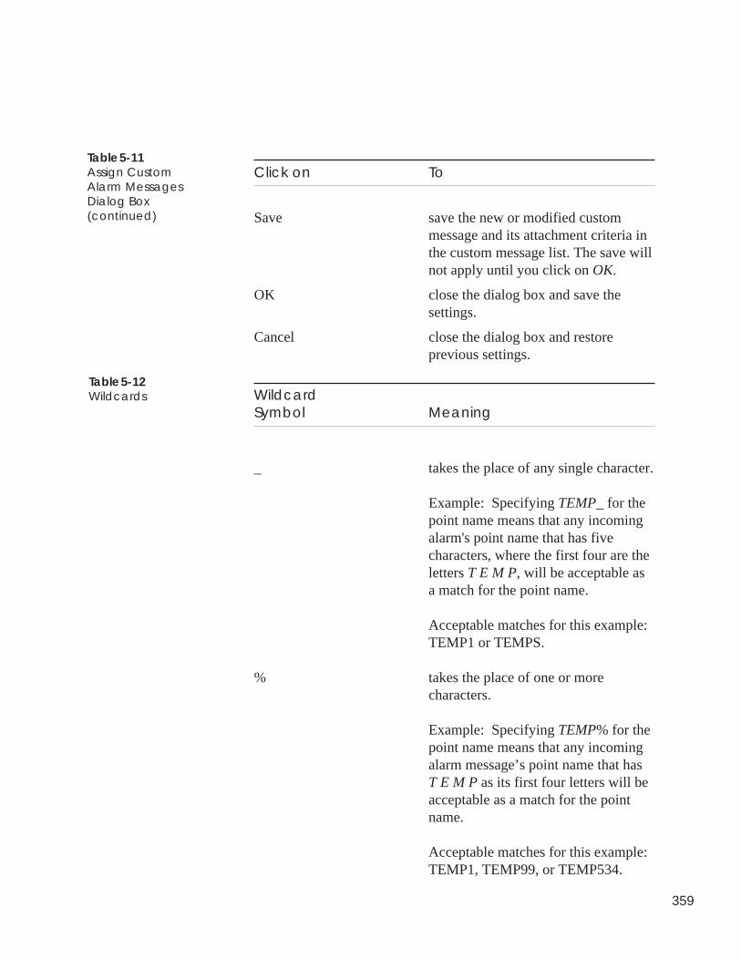
359
Click on To
Save save the new or modified custommessage and its attachment criteria inthe custom message list. The save willnot apply until you click on OK.
OK close the dialog box and save thesettings.
Cancel close the dialog box and restoreprevious settings.
WildcardSymbol Meaning
_ takes the place of any single character.
Example: Specifying TEMP_ for thepoint name means that any incomingalarm's point name that has fivecharacters, where the first four are theletters T E M P, will be acceptable asa match for the point name.
Acceptable matches for this example:TEMP1 or TEMPS.
% takes the place of one or morecharacters.
Example: Specifying TEMP% for thepoint name means that any incomingalarm message’s point name that hasT E M P as its first four letters will beacceptable as a match for the pointname.
Acceptable matches for this example:TEMP1, TEMP99, or TEMP534.
Table 5-11Assign CustomAlarm MessagesDialog Box(continued)
Table 5-12Wildcards
360
This section provides information on:
• the definition of a WorkSPACE.
• how to determine if an alarm has a WorkSPACE.
• how to assign a WorkSPACE to an existing alarm.
A WorkSPACE is a group of windows containing graphics and trendplots of CCN data. You use the ComfortVIEW WorkSPACE Man-ager application to create and view WorkSPACEs. For example, youcould set up a WorkSPACE to include a temperature trend, and agraphic of the associated chilled water system. You can then displaythese windows simultaneously.
As part of the ComfortVIEW Alarm Manager application, you setup links between alarms and WorkSPACEs. This gives you theability to jump from the Alarm List window to the WorkSPACEManager application and view the graphic, or trend plot that pertainsto the selected alarm.
You will know if an alarm has an associated WorkSPACE by look-ing at the WorkSPACE icon that appears in the alarm-specifictoolbar below the alarm message. If the icon does not appear to beactivated (is not a blue color), a WorkSPACE has not been assignedto this alarm. To assign a WorkSPACE to an alarm, refer to theAssigning a WorkSPACE to an Existing Alarm section that follows.
Displayingan Existing
Alarm’sWorkSPACE
Determining if anAlarm Has anAssociated WorkSPACE
What is aWorkSPACE?
361
Follow the steps below to display an existing alarm’s associatedWorkSPACE.
Note: You may also display an alarm’s WorkSPACE by follow-ing the Flashing Icon Alarm Viewing instructions, whichcan be found in the Viewing New and UnacknowledgedAlarms section of this chapter. Then click on the alarmwindow’s WorkSPACE icon.
1. Display the alarm list. If necessary, refer to the instructionslisted under Viewing the Alarm List.
2. Click on the blue WorkSPACE icon that appears in the alarm-specific toolbar below the alarm message.
ComfortVIEW will invoke the WorkSPACE Manager appli-cation and display the WorkSPACE that has been assigned tothis alarm.
Follow the steps below to assign a WorkSPACE to an existingalarm:
1. Display the alarm list. If necessary, refer to the instructionslisted under Viewing the Alarm List.
2. Select the alarm message or messages to which you wish toattach a WorkSPACE. If you need additional information,refer to the Selecting Alarms section of this chapter.
3. Click on the Functions menu item and then click on AttachWorkSPACE.
Note: You may also perform this command by clicking onthe non-blue WorkSPACE icon that appears in thealarm-specific toolbar below the alarm message.
DisplayingWorkSPACEs
Assigning aWorkSPACE to anExisting Alarm
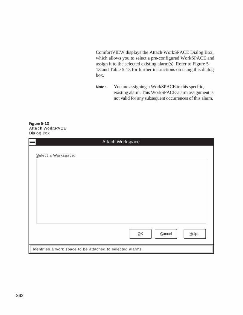
362
ComfortVIEW displays the Attach WorkSPACE Dialog Box,which allows you to select a pre-configured WorkSPACE andassign it to the selected existing alarm(s). Refer to Figure 5-13 and Table 5-13 for further instructions on using this dialogbox.
Note: You are assigning a WorkSPACE to this specific,existing alarm. This WorkSPACE-alarm assignment isnot valid for any subsequent occurrences of this alarm.
Figure 5-13Attach WorkSPACEDialog Box
Attach Workspace
OK Cancel Help...
Select a Workspace:
Identifies a work space to be attached to selected alarms
363
Click on To
A WorkSPACE in the list select it.
Help display help information.
OK close the dialog box and attach theselected WorkSPACE to the selectedalarm.
Cancel exit the dialog box and restore theprevious settings. Any changes made arenot saved.
Follow the steps below to change an alarm’s WorkSPACE assign-ment:
1. Display the alarm list. If necessary, refer to the instructionslisted under Viewing the Alarm List.
2. Select the alarm message or messages whose WorkSPACE linkyou wish to modify by clicking on the appropriate messages.The background of the selected messages is highlighted. Thisindicates that a message is “selected.” If you need additionalinformation on selecting alarms, refer to the Selecting Alarmssection of this chapter.
3. Click on the Functions menu item and then click on AttachWorkSPACE.
ComfortVIEW displays the Attach WorkSPACE Dialog Box,which allows you to assign a WorkSPACE to this alarm. Selecta WorkSPACE from the list of pre-configured WorkSPACEs,and click on OK.
Note: You are assigning a WorkSPACE to this specificexisting alarm. This WorkSPACE-alarm assignment isnot valid for any subsequent occurrences of this alarm.Refer to Figure 5-13 and Table 5-13 for further in-structions on using this dialog box.
Table 5-13Attach WorkSPACEDialog Box
Modifying an ExistingAlarm’s WorkSPACE
364
A WorkSPACE is a group of windows containing graphics andtrend plots of CCN data. You use the ComfortVIEW WorkSPACEManager application to create and view WorkSPACEs. For ex-ample, you could set up a WorkSPACE to include a plot of tempera-ture, and a graphic of the associated chilled water system. You couldthen display these windows simultaneously.
As part of the ComfortVIEW Alarm Manager application, you setup links between alarms and WorkSPACEs. This gives you theability to jump from the Alarm List window to the WorkSPACEManager and view the graphic or trend plot that is pertinent to theselected alarm.
You set the criteria (Area, Zone, Element, Point, and Precedence)for attaching WorkSPACEs to incoming alarms. ComfortVIEWcompares incoming alarms to your specified criteria and establishesalarm-WorkSPACE links using the following rules:
ComfortVIEW begins by identifying any criteria that might qualifythe WorkSPACE for attachment. One possibility that will qualify aWorkSPACE for attachment to an alarm is an exact match betweenyour user-defined criteria and the incoming alarm. Other possibili-ties involve any wildcards that you use to specify criteria. IfComfortVIEW does not find any set of user-defined criteria thatqualify for attachment, then the alarm will not have a WorkSPACEattached.For example, you may have one generic WorkSpace that is config-
AssigningWorkSPACES toIncoming Alarms
What is a WorkSPACE?
Rules for WorkSPACEAssignment
365
ured for attachment to every air handler alarm, and anotherWorkSPACE that is configured for attachment to air handler fanstatus alarms specifically. To ensure that the fan status WorkSPACEgets attached to air handler fans status alarms, you should assign ahigher precedence to the fan status WorkSPACE than to the genericair handler WorkSPACE. You would assign the fan statusWorkSPACE a precedence of Very High, and the air handlerWorkSPACE a precedence of Medium. If more than oneWorkSPACE qualifies for attachment, ComfortVIEW uses the onewith the highest user-specified precedence.
Follow these steps to assign a WorkSPACE to an incoming alarm orto modify an existing WorkSPACE-incoming alarm assignment:
1. Display the alarm list. If necessary, refer to the instructionslisted under Viewing the Alarm List.
2. Click on Configure and then click on WorkSPACEs.
ComfortVIEW displays the Assign WorkSPACEs dialog box.This dialog box gives you the capability to select aWorkSPACE. It also enables you to identify the criteria forthose incoming alarms to which you want the WorkSPACEattached.
The names of all currently-assigned WorkSPACEs appear inthe box below Select a WorkSPACE. As you scroll down thelist and highlight each WorkSPACE, you can see its associ-ated Area, Zone, Element, Level, Point, and Precedence onthe bottom of the window.
3. Do one of the following, depending on whether you want toadd, modify, or delete a WorkSPACE:
• Click on Add to establish a new WorkSPACE-incomingalarm assignment, or
• Select a WorkSPACE and then click on Modify to changea WorkSPACE or its associated incoming alarm criteria,or
• Select a WorkSPACE and then click on Delete to remove
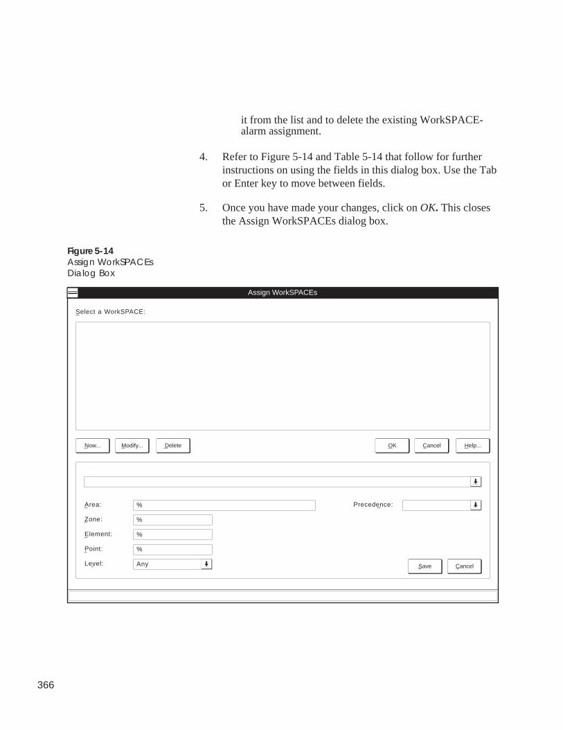
366
it from the list and to delete the existing WorkSPACE-alarm assignment.
4. Refer to Figure 5-14 and Table 5-14 that follow for furtherinstructions on using the fields in this dialog box. Use the Tabor Enter key to move between fields.
5. Once you have made your changes, click on OK. This closesthe Assign WorkSPACEs dialog box.
Figure 5-14Assign WorkSPACEsDialog Box
Assign WorkSPACEs
Select a WorkSPACE:
Save Cancel
OK Cancel Help...Now... Modify... Delete
Precedence:Area:
Zone:
Element:
Point:
Level:
%
%
%
%
Any
367
Click on To
Add establish a new WorkSPACE-incom-ing alarm assignment. The AddWorkSPACE Assignment line dis-plays the names of existingWorkSPACEs. Use the down arrow todisplay the list of all WorkSPACEs.
Then specify the Area, Zone, Element,Point, Level, and Precedence ofincoming alarms to attach to thisWorkSPACE. Each field is describedbelow. Use the Tab or Enter key tomove between fields.
Note: If you leave a field blank,ComfortVIEW automatically fillsthis field with the _ (wildcard). Referto Table 5-15 that follows for a listand explanation of allowed wildcards.
Click on Save to display the newly-assigned WorkSPACE in the list ofWorkSPACEs on the top of thewindow. You must click on OK to exitthis dialog box and and save the newWorkSPACE-incoming alarm assign-ment.
Modify identify a new WorkSPACE to beassigned to the displayed incomingalarm criteria, or to modify the dis-played incoming alarm criteria. Youmust select the WorkSPACE you wishto modify before clicking on Modify.
(continued)
Table 5-14Assign WorkSPACEsDialog Box
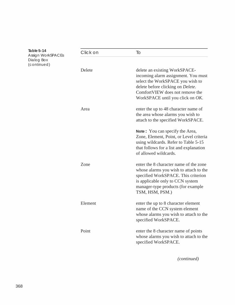
368
Click on To
Delete delete an existing WorkSPACE-incoming alarm assignment. You mustselect the WorkSPACE you wish todelete before clicking on Delete.ComfortVIEW does not remove theWorkSPACE until you click on OK.
Area enter the up to 48 character name ofthe area whose alarms you wish toattach to the specified WorkSPACE.
Note: You can specify the Area,Zone, Element, Point, or Level criteriausing wildcards. Refer to Table 5-15that follows for a list and explanationof allowed wildcards.
Zone enter the 8 character name of the zonewhose alarms you wish to attach to thespecified WorkSPACE. This criterionis applicable only to CCN systemmanager-type products (for exampleTSM, HSM, PSM.)
Element enter the up to 8 character elementname of the CCN system elementwhose alarms you wish to attach to thespecified WorkSPACE.
Point enter the 8 character name of pointswhose alarms you wish to attach to thespecified WorkSPACE.
(continued)
Table 5-14Assign WorkSPACEsDialog Box(continued)
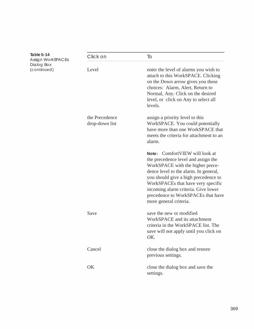
369
Table 5-14Assign WorkSPACEsDialog Box(continued)
Click on To
Level enter the level of alarms you wish toattach to this WorkSPACE. Clickingon the Down arrow gives you thesechoices: Alarm, Alert, Return toNormal, Any. Click on the desiredlevel, or click on Any to select alllevels.
the Precedence assign a priority level to thisdrop-down list WorkSPACE. You could potentially
have more than one WorkSPACE thatmeets the criteria for attachment to analarm.
Note: ComfortVIEW will look atthe precedence level and assign theWorkSPACE with the higher prece-dence level to the alarm. In general,you should give a high precedence toWorkSPACEs that have very specificincoming alarm criteria. Give lowerprecedence to WorkSPACEs that havemore general criteria.
Save save the new or modifiedWorkSPACE and its attachmentcriteria in the WorkSPACE list. Thesave will not apply until you click onOK.
Cancel close the dialog box and restoreprevious settings.
OK close the dialog box and save thesettings.
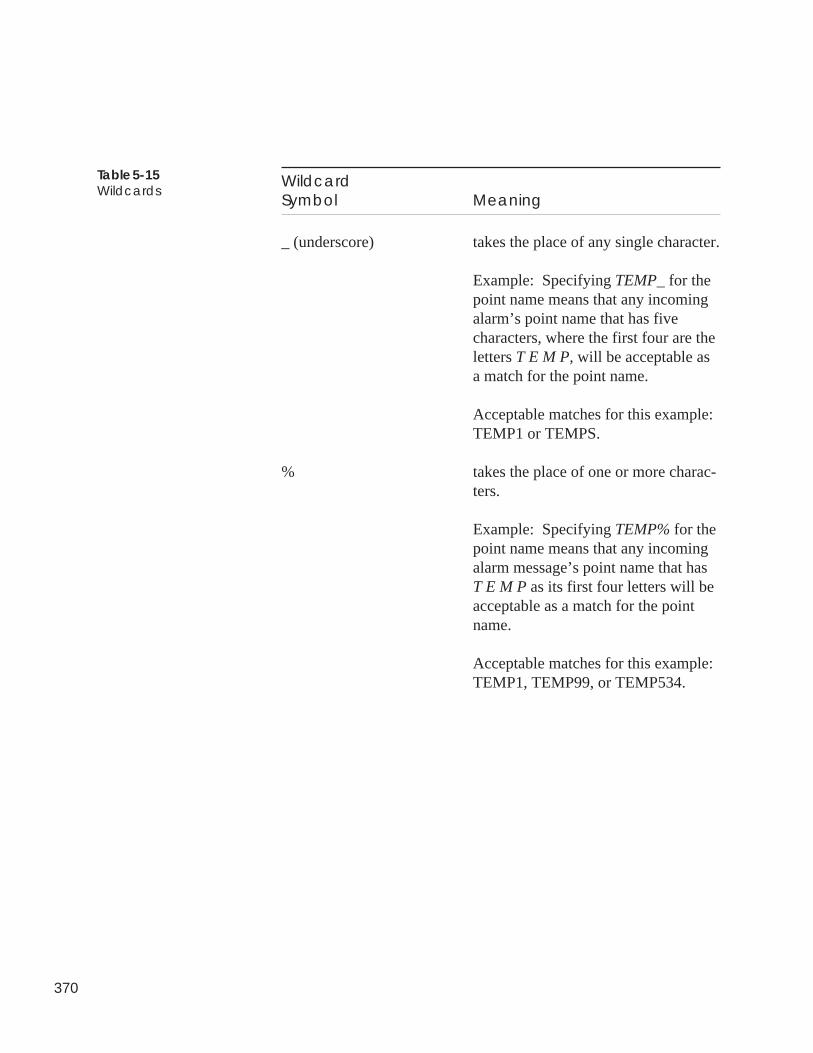
370
WildcardSymbol Meaning
_ (underscore) takes the place of any single character.
Example: Specifying TEMP_ for thepoint name means that any incomingalarm’s point name that has fivecharacters, where the first four are theletters T E M P, will be acceptable asa match for the point name.
Acceptable matches for this example:TEMP1 or TEMPS.
% takes the place of one or more charac-ters.
Example: Specifying TEMP% for thepoint name means that any incomingalarm message’s point name that hasT E M P as its first four letters will beacceptable as a match for the pointname.
Acceptable matches for this example:TEMP1, TEMP99, or TEMP534.
Table 5-15Wildcards
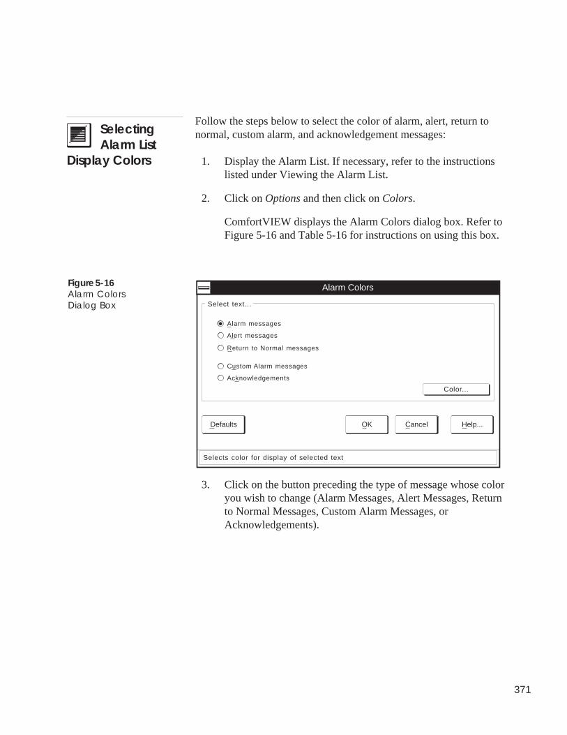
371
SelectingAlarm List
Display Colors
Follow the steps below to select the color of alarm, alert, return tonormal, custom alarm, and acknowledgement messages:
1. Display the Alarm List. If necessary, refer to the instructionslisted under Viewing the Alarm List.
2. Click on Options and then click on Colors.
ComfortVIEW displays the Alarm Colors dialog box. Refer toFigure 5-16 and Table 5-16 for instructions on using this box.
3. Click on the button preceding the type of message whose coloryou wish to change (Alarm Messages, Alert Messages, Returnto Normal Messages, Custom Alarm Messages, orAcknowledgements).
Figure 5-16Alarm ColorsDialog Box
Acknowledgements
Custom Alarm messages
Return to Normal messages
Alarm messages
Alert messages
Alarm Colors
Select text...
Selects color for display of selected text
OK Cancel Help...Defaults
Color...
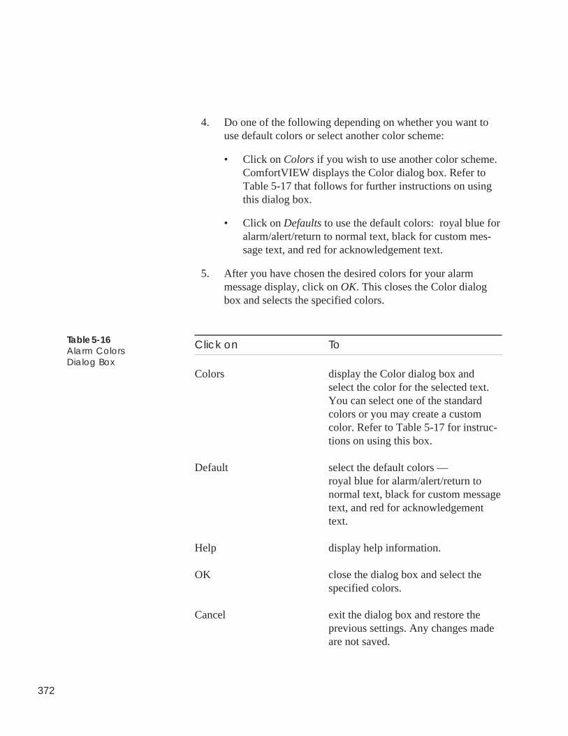
372
4. Do one of the following depending on whether you want touse default colors or select another color scheme:
• Click on Colors if you wish to use another color scheme.ComfortVIEW displays the Color dialog box. Refer toTable 5-17 that follows for further instructions on usingthis dialog box.
• Click on Defaults to use the default colors: royal blue foralarm/alert/return to normal text, black for custom mes-sage text, and red for acknowledgement text.
5. After you have chosen the desired colors for your alarmmessage display, click on OK. This closes the Color dialogbox and selects the specified colors.
Click on To
Colors display the Color dialog box andselect the color for the selected text.You can select one of the standardcolors or you may create a customcolor. Refer to Table 5-17 for instruc-tions on using this box.
Default select the default colors —royal blue for alarm/alert/return tonormal text, black for custom messagetext, and red for acknowledgementtext.
Help display help information.
OK close the dialog box and select thespecified colors.
Cancel exit the dialog box and restore theprevious settings. Any changes madeare not saved.
Table 5-16Alarm ColorsDialog Box
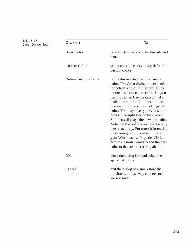
373
Table 5-17Color Dialog Box Click on To
Basic Color select a standard color for the selectedtext.
Custom Color select one of the previously-definedcustom colors.
Define Custom Colors refine the selected basic or customcolor. The Color dialog box expandsto include a color refiner box. Clickon the basic or custom color that youwish to refine. Use the cursor that isinside the color refiner box and thevertical luminosity bar to change thecolor. You may also type values in theboxes. The right side of the Color/Solid box displays the new text color.Note that the Solid colors are the onlyones that apply. For more informationon defining custom colors, refer toyour Windows user’s guide. Click onAdd to Custom Colors to add the newcolor to the custom colors palette.
OK close the dialog box and select thespecified colors.
Cancel exit the dialog box and restore theprevious settings. Any changes madeare not saved.
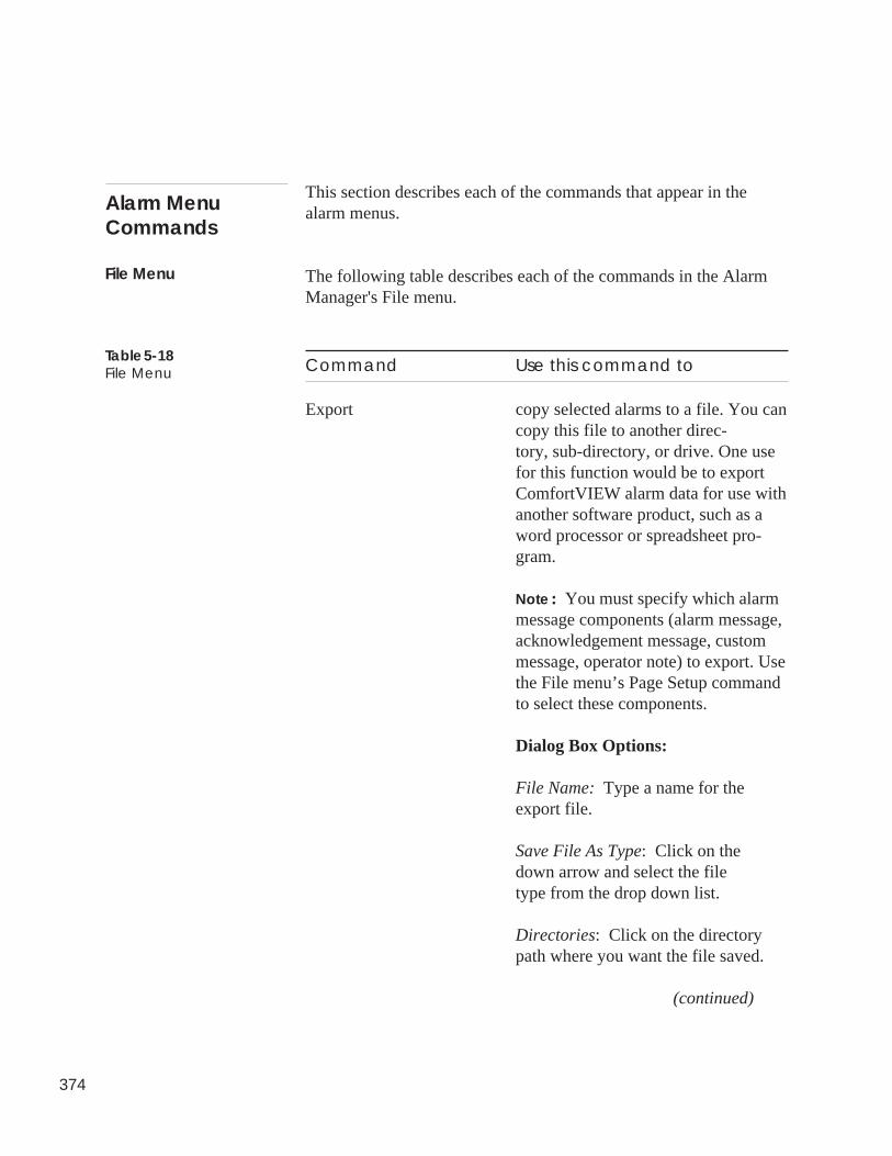
374
File Menu
Alarm MenuCommands
Table 5-18File Menu
This section describes each of the commands that appear in thealarm menus.
The following table describes each of the commands in the AlarmManager's File menu.
Command Use this command to
Export copy selected alarms to a file. You cancopy this file to another direc-tory, sub-directory, or drive. One usefor this function would be to exportComfortVIEW alarm data for use withanother software product, such as aword processor or spreadsheet pro-gram.
Note: You must specify which alarmmessage components (alarm message,acknowledgement message, custommessage, operator note) to export. Usethe File menu’s Page Setup commandto select these components.
Dialog Box Options:
File Name: Type a name for theexport file.
Save File As Type: Click on thedown arrow and select the filetype from the drop down list.
Directories: Click on the directorypath where you want the file saved.
(continued)
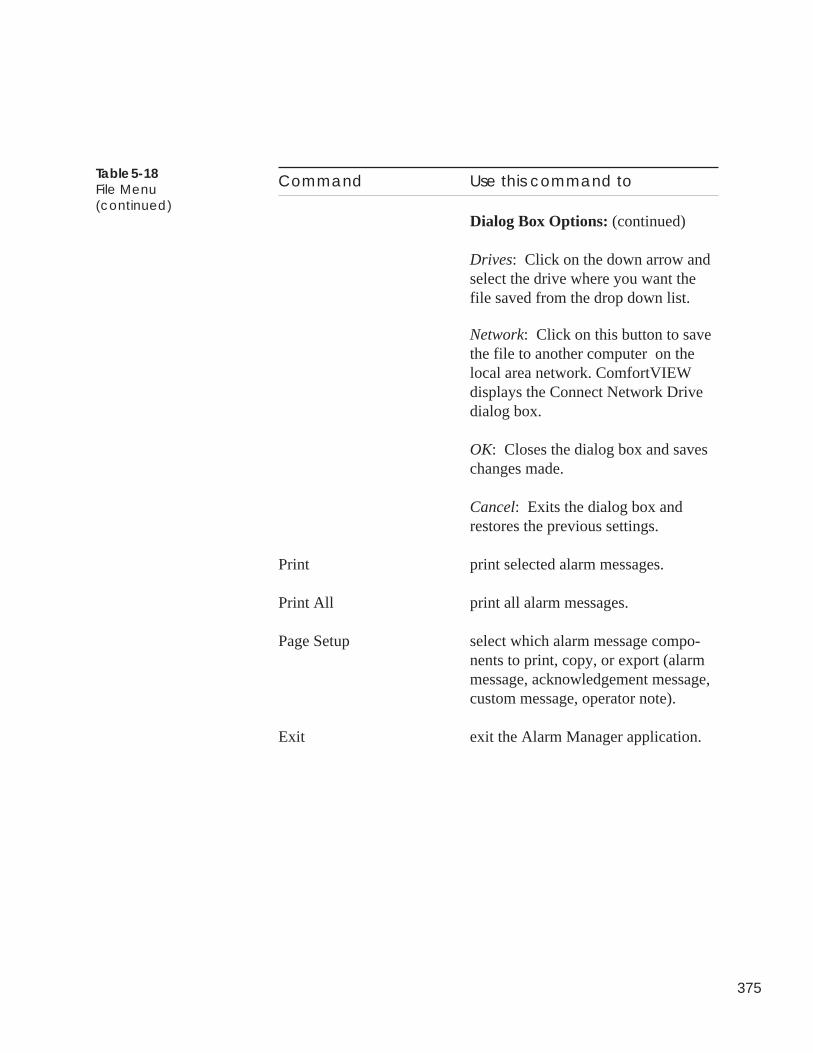
375
Command Use this command to
Dialog Box Options: (continued)
Drives: Click on the down arrow andselect the drive where you want thefile saved from the drop down list.
Network: Click on this button to savethe file to another computer on thelocal area network. ComfortVIEWdisplays the Connect Network Drivedialog box.
OK: Closes the dialog box and saveschanges made.
Cancel: Exits the dialog box andrestores the previous settings.
Print print selected alarm messages.
Print All print all alarm messages.
Page Setup select which alarm message compo-nents to print, copy, or export (alarmmessage, acknowledgement message,custom message, operator note).
Exit exit the Alarm Manager application.
Table 5-18File Menu(continued)
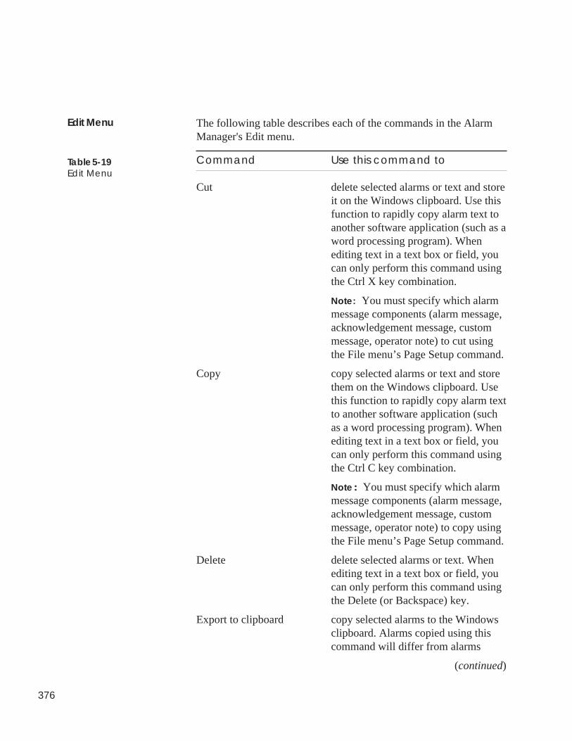
376
The following table describes each of the commands in the AlarmManager's Edit menu.
Command Use this command to
Cut delete selected alarms or text and storeit on the Windows clipboard. Use thisfunction to rapidly copy alarm text toanother software application (such as aword processing program). Whenediting text in a text box or field, youcan only perform this command usingthe Ctrl X key combination.
Note: You must specify which alarmmessage components (alarm message,acknowledgement message, custommessage, operator note) to cut usingthe File menu’s Page Setup command.
Copy copy selected alarms or text and storethem on the Windows clipboard. Usethis function to rapidly copy alarm textto another software application (suchas a word processing program). Whenediting text in a text box or field, youcan only perform this command usingthe Ctrl C key combination.
Note: You must specify which alarmmessage components (alarm message,acknowledgement message, custommessage, operator note) to copy usingthe File menu’s Page Setup command.
Delete delete selected alarms or text. Whenediting text in a text box or field, youcan only perform this command usingthe Delete (or Backspace) key.
Export to clipboard copy selected alarms to the Windowsclipboard. Alarms copied using thiscommand will differ from alarms
(continued)
Edit Menu
Table 5-19Edit Menu
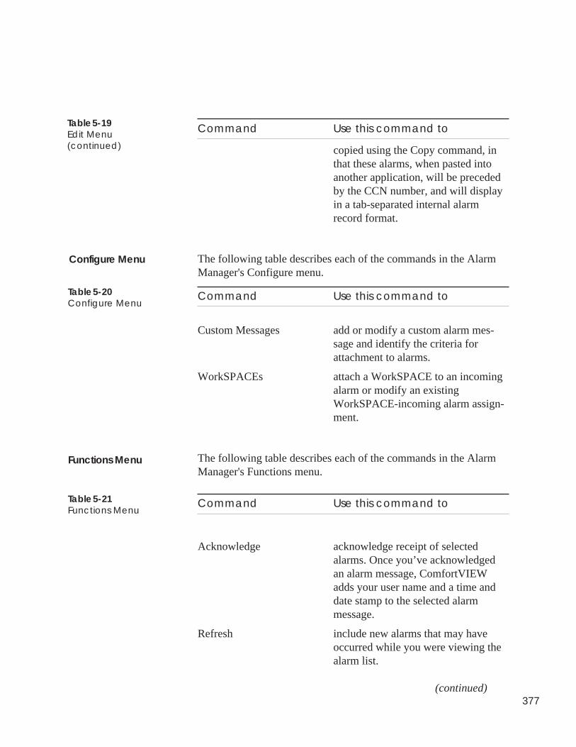
377
Command Use this command to
copied using the Copy command, inthat these alarms, when pasted intoanother application, will be precededby the CCN number, and will displayin a tab-separated internal alarmrecord format.
The following table describes each of the commands in the AlarmManager's Configure menu.
Command Use this command to
Custom Messages add or modify a custom alarm mes-sage and identify the criteria forattachment to alarms.
WorkSPACEs attach a WorkSPACE to an incomingalarm or modify an existingWorkSPACE-incoming alarm assign-ment.
The following table describes each of the commands in the AlarmManager's Functions menu.
Command Use this command to
Acknowledge acknowledge receipt of selectedalarms. Once you’ve acknowledgedan alarm message, ComfortVIEWadds your user name and a time anddate stamp to the selected alarmmessage.
Refresh include new alarms that may haveoccurred while you were viewing thealarm list.
(continued)
Table 5-19Edit Menu(continued)
Configure Menu
Table 5-20Configure Menu
Functions Menu
Table 5-21Functions Menu
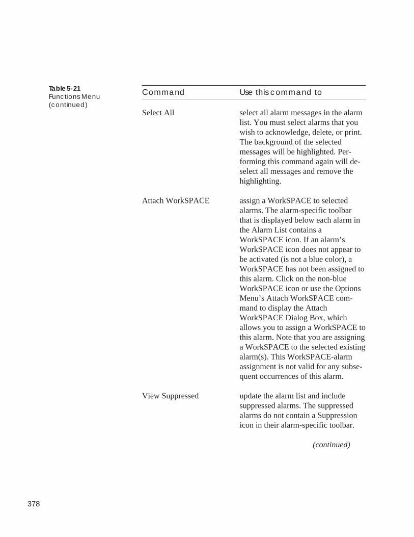
378
Command Use this command to
Select All select all alarm messages in the alarmlist. You must select alarms that youwish to acknowledge, delete, or print.The background of the selectedmessages will be highlighted. Per-forming this command again will de-select all messages and remove thehighlighting.
Attach WorkSPACE assign a WorkSPACE to selectedalarms. The alarm-specific toolbarthat is displayed below each alarm inthe Alarm List contains aWorkSPACE icon. If an alarm’sWorkSPACE icon does not appear tobe activated (is not a blue color), aWorkSPACE has not been assigned tothis alarm. Click on the non-blueWorkSPACE icon or use the OptionsMenu’s Attach WorkSPACE com-mand to display the AttachWorkSPACE Dialog Box, whichallows you to assign a WorkSPACE tothis alarm. Note that you are assigninga WorkSPACE to the selected existingalarm(s). This WorkSPACE-alarmassignment is not valid for any subse-quent occurrences of this alarm.
View Suppressed update the alarm list and includesuppressed alarms. The suppressedalarms do not contain a Suppressionicon in their alarm-specific toolbar.
(continued)
Table 5-21Functions Menu(continued)
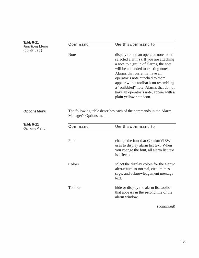
379
Table 5-21Functions Menu(continued)
Command Use this command to
Note display or add an operator note to theselected alarm(s). If you are attachinga note to a group of alarms, the notewill be appended to existing notes.Alarms that currently have anoperator’s note attached to themappear with a toolbar icon resemblinga “scribbled” note. Alarms that do nothave an operator’s note, appear with aplain yellow note icon.
The following table describes each of the commands in the AlarmManager's Options menu.
Command Use this command to
Font change the font that ComfortVIEWuses to display alarm list text. Whenyou change the font, all alarm list textis affected.
Colors select the display colors for the alarm/alert/return-to-normal, custom mes-sage, and acknowledgement messagetext.
Toolbar hide or display the alarm list toolbarthat appears in the second line of thealarm window.
(continued)
Options Menu
Table 5-22Options Menu
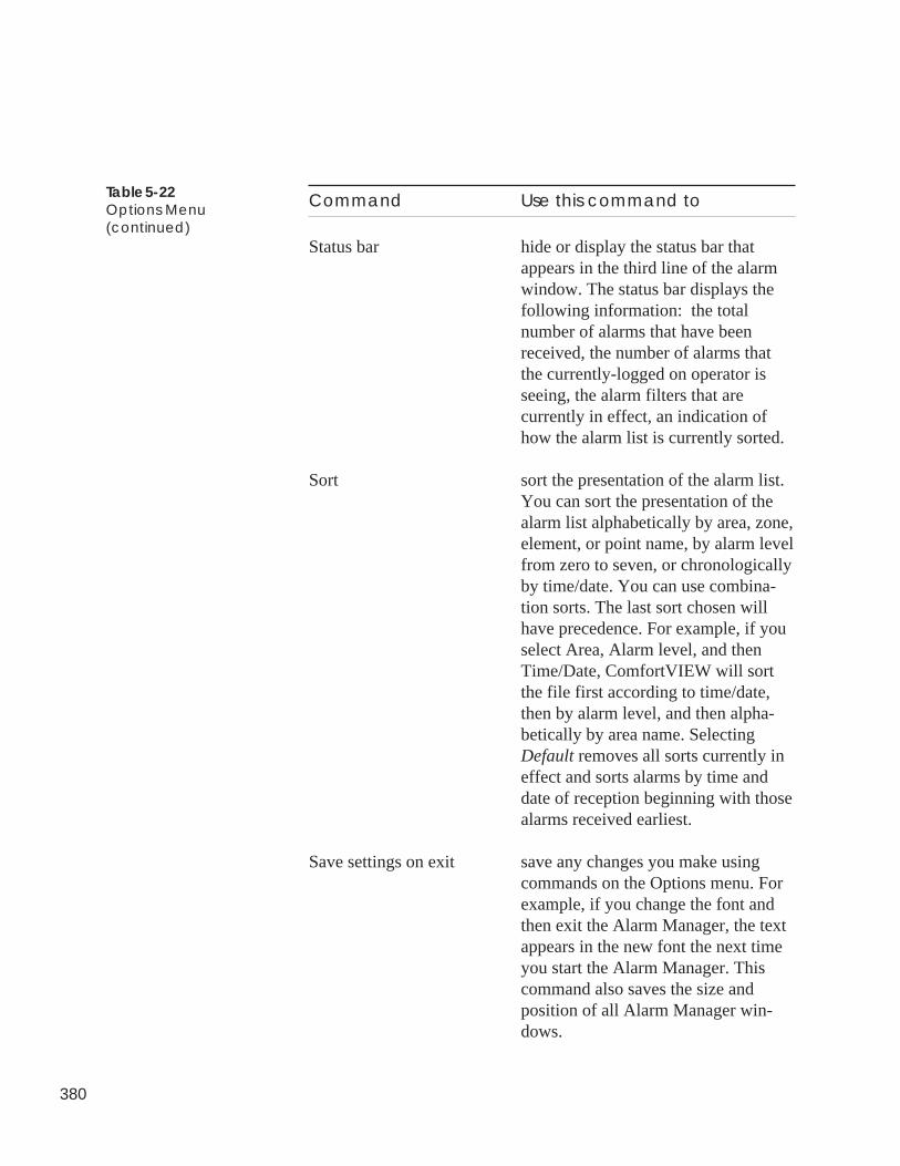
380
Table 5-22Options Menu(continued)
Command Use this command to
Status bar hide or display the status bar thatappears in the third line of the alarmwindow. The status bar displays thefollowing information: the totalnumber of alarms that have beenreceived, the number of alarms thatthe currently-logged on operator isseeing, the alarm filters that arecurrently in effect, an indication ofhow the alarm list is currently sorted.
Sort sort the presentation of the alarm list.You can sort the presentation of thealarm list alphabetically by area, zone,element, or point name, by alarm levelfrom zero to seven, or chronologicallyby time/date. You can use combina-tion sorts. The last sort chosen willhave precedence. For example, if youselect Area, Alarm level, and thenTime/Date, ComfortVIEW will sortthe file first according to time/date,then by alarm level, and then alpha-betically by area name. SelectingDefault removes all sorts currently ineffect and sorts alarms by time anddate of reception beginning with thosealarms received earliest.
Save settings on exit save any changes you make usingcommands on the Options menu. Forexample, if you change the font andthen exit the Alarm Manager, the textappears in the new font the next timeyou start the Alarm Manager. Thiscommand also saves the size andposition of all Alarm Manager win-dows.
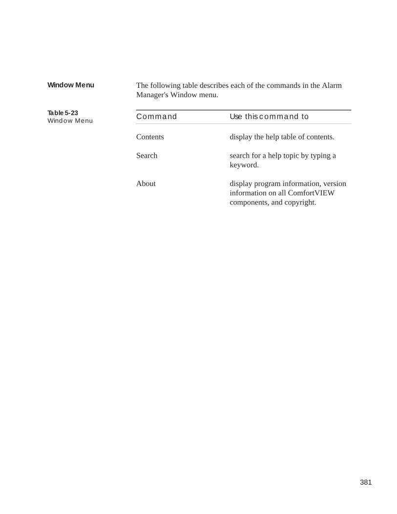
381
The following table describes each of the commands in the AlarmManager's Window menu.
Command Use this command to
Contents display the help table of contents.
Search search for a help topic by typing akeyword.
About display program information, versioninformation on all ComfortVIEWcomponents, and copyright.
Window Menu
Table 5-23Window Menu

382
Setup

Alarm Manager
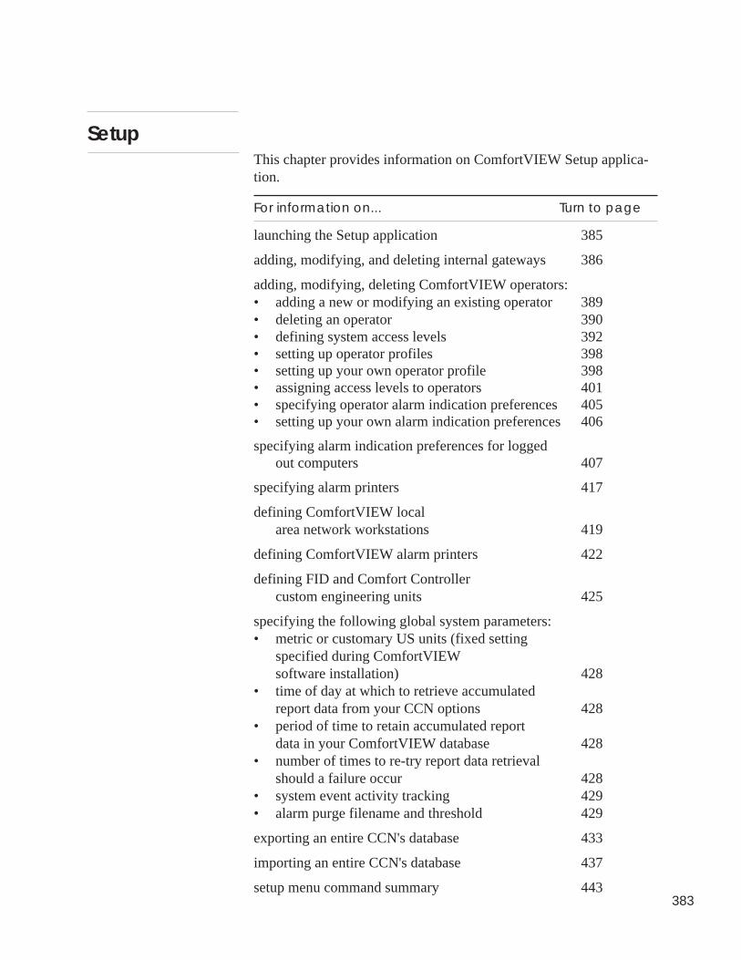
383
This chapter provides information on ComfortVIEW Setup applica-tion.
For information on... Turn to page
launching the Setup application 385
adding, modifying, and deleting internal gateways 386
adding, modifying, deleting ComfortVIEW operators:• adding a new or modifying an existing operator 389• deleting an operator 390• defining system access levels 392• setting up operator profiles 398• setting up your own operator profile 398• assigning access levels to operators 401• specifying operator alarm indication preferences 405• setting up your own alarm indication preferences 406
specifying alarm indication preferences for loggedout computers 407
specifying alarm printers 417
defining ComfortVIEW localarea network workstations 419
defining ComfortVIEW alarm printers 422
defining FID and Comfort Controllercustom engineering units 425
specifying the following global system parameters:• metric or customary US units (fixed setting
specified during ComfortVIEWsoftware installation) 428
• time of day at which to retrieve accumulatedreport data from your CCN options 428
• period of time to retain accumulated reportdata in your ComfortVIEW database 428
• number of times to re-try report data retrievalshould a failure occur 428
• system event activity tracking 429• alarm purge filename and threshold 429
exporting an entire CCN's database 433
importing an entire CCN's database 437
setup menu command summary 443
Setup
384
The following terms are used throughout this chapter.
Client — A computer on a local area network runningComfortVIEW communication and user interface software, orComfortVIEW user interface software only.
Server — A computer on a local area network runningComfortVIEW communication, user interface, service, and databasesoftware.
You use ComfortVIEW Setup application to add or define thefollowing:
• ComfortVIEW operators
• ComfortVIEW local area network workstation names
• Alarm printer names and port locations
• Global parameters:
• Metric or customary US units (fixed setting chosen at instal-lation)
• Time of day at which to retrieve accumulated report datafrom your CCN options
• Period of time to retain accumulated report data in yourComfortVIEW database
• Number of times to re-try report data retrieval should afailure occur.
• Enable/disable of system activity event logging.
• Enable/disable automatic ComfortVIEW login inconjunction with Windows NT login.
• Enable/disable of automatic alarm deletion, including purgefilename and threshold.
You can also use the Setup application to export or import an entireCCN's database.
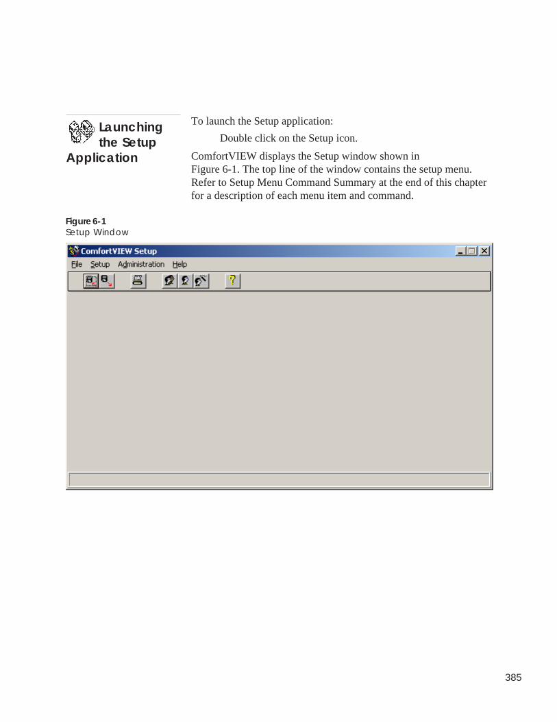
385
To launch the Setup application:
Double click on the Setup icon.
ComfortVIEW displays the Setup window shown inFigure 6-1. The top line of the window contains the setup menu.Refer to Setup Menu Command Summary at the end of this chapterfor a description of each menu item and command.
Launchingthe Setup
Application
Figure 6-1Setup Window
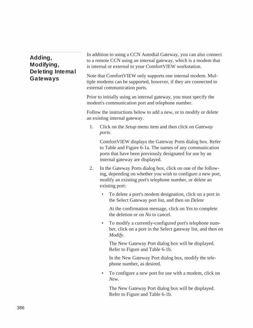
386
In addition to using a CCN Autodial Gateway, you can also connectto a remote CCN using an internal gateway, which is a modem thatis internal or external to your ComfortVIEW workstation.
Note that ComfortVIEW only supports one internal modem. Mul-tiple modems can be supported, however, if they are connected toexternal communication ports.
Prior to initially using an internal gateway, you must specify themodem's communication port and telephone number.
Follow the instructions below to add a new, or to modify or deletean existing internal gateway.
1. Click on the Setup menu item and then click on Gatewayports.
ComfortVIEW displays the Gateway Ports dialog box. Referto Table and Figure 6-1a. The names of any communicationports that have been previously designated for use by aninternal gateway are displayed.
2. In the Gateway Ports dialog box, click on one of the follow-ing, depending on whether you wish to configure a new port,modify an existing port's telephone number, or delete anexisting port:
• To delete a port's modem designation, click on a port inthe Select Gateway port list, and then on Delete
At the confirmation message, click on Yes to completethe deletion or on No to cancel.
• To modify a currently-configured port's telephone num-ber, click on a port in the Select gateway list, and then onModify.
The New Gateway Port dialog box will be displayed.Refer to Figure and Table 6-1b.
In the New Gateway Port dialog box, modify the tele-phone number, as desired.
• To configure a new port for use with a modem, click onNew.
The New Gateway Port dialog box will be displayed.Refer to Figure and Table 6-1b.
Adding,Modifying,Deleting InternalGateways
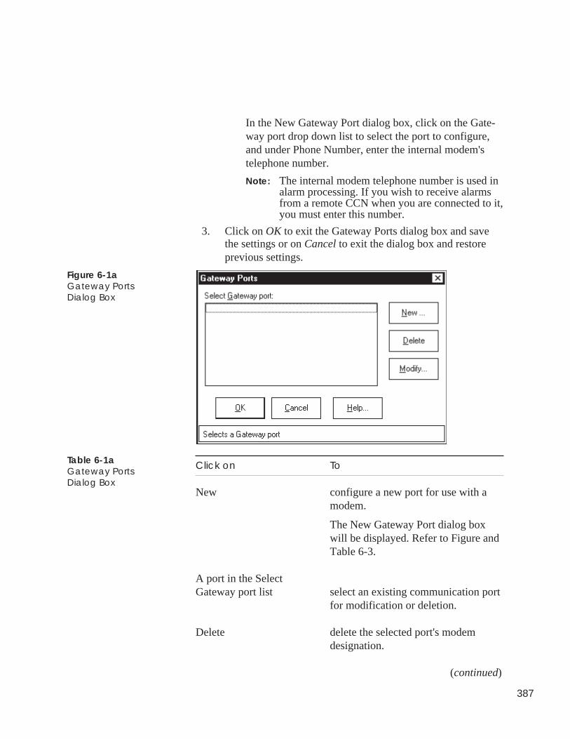
387
In the New Gateway Port dialog box, click on the Gate-way port drop down list to select the port to configure,and under Phone Number, enter the internal modem'stelephone number.
Note: The internal modem telephone number is used inalarm processing. If you wish to receive alarmsfrom a remote CCN when you are connected to it,you must enter this number.
3. Click on OK to exit the Gateway Ports dialog box and savethe settings or on Cancel to exit the dialog box and restoreprevious settings.
Figure 6-1aGateway PortsDialog Box
Click on To
New configure a new port for use with amodem.
The New Gateway Port dialog boxwill be displayed. Refer to Figure andTable 6-3.
A port in the SelectGateway port list select an existing communication port
for modification or deletion.
Delete delete the selected port's modemdesignation.
(continued)
Table 6-1aGateway PortsDialog Box

388
Click on To
Modify modify the telephone number of theselected port.
OK close the dialog box and save changesmade.
Cancel exit the dialog box and restore theprevious settings. Any changes madeare not saved.
Help display help information.
Table 6-1aGateway PortsDialog Box(continued)
Figure 6-1bNew Gateway PortDialog Box
Click on To
the Gateway port dropdown list select the communication port to
configure.
Phone number enter or modify the internal modem'stelephone number.
Note: The internal modem telephonenumber is used in alarmprocessing. If you wish toreceive alarms from a remoteCCN when you are connectedto it, you must enter thisnumber.
(continued)
Table 6-1bNew Gateway PortDialog Box
389
Click on To
OK close the dialog box and save changesmade.
Cancel exit the dialog box and restore theprevious settings. Any changes madeare not saved.
Help display help information.
ComfortVIEW can support up to 100 different operators.
To quickly and easily add a new ComfortVIEW operator, click onthe Operator Profile toolbar wizard shown at left. The wizard guidesyou through the following setup functions:
• Setting up the operator profile (operator and login name, pass-word, and alarm indication preference)
• Defining system access levels and assigning access levels to theoperator
• Specifying alarm indication preferences.
To modify an existing ComfortVIEW operator, follow the instruc-tions below.
Click on the Administration menu item and then click onOperators.
Note: You may also perform this command by clicking onthe Modify Operator Profiles icon in the toolbar.
ComfortVIEW displays the Operator Configuration dialogbox. The names of all existing ComfortVIEW operatorsdisplay under Select an Operator.
Refer to Figure 6-2 and Table 6-2 for further instructions onusing the Operator Configuration box.
Table 6-1bNew Gateway PortDialog Box(continued)
Adding,Modifying,
DeletingOperators
To Add a NewOperator
To Modify an ExistingOperator
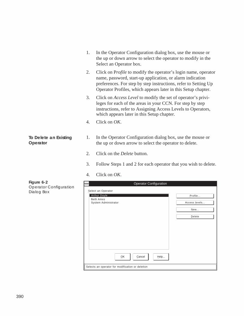
390
1. In the Operator Configuration dialog box, use the mouse orthe up or down arrow to select the operator to modify in theSelect an Operator box.
2. Click on Profile to modify the operator’s login name, operatorname, password, start-up application, or alarm indicationpreferences. For step by step instructions, refer to Setting UpOperator Profiles, which appears later in this Setup chapter.
3. Click on Access Level to modify the set of operator’s privi-leges for each of the areas in your CCN. For step by stepinstructions, refer to Assigning Access Levels to Operators,which appears later in this Setup chapter.
4. Click on OK.
1. In the Operator Configuration dialog box, use the mouse orthe up or down arrow to select the operator to delete.
2. Click on the Delete button.
3. Follow Steps 1 and 2 for each operator that you wish to delete.
4. Click on OK.
To Delete an ExistingOperator
Select an Operator
Operator Configuration
OK Cancel Help...
Profile...
Access levels...
New...
Delete
Arthur Doyle
Selects an operator for modification or deletion
Beth AmesSystem Administrator
Figure 6-2Operator ConfigurationDialog Box
391
Table 6-2Operator ConfigurationDialog Box
Click on To
Select an Operator: list select an operator to modify or delete.
Profile display the Operator Profile dialogbox. This box gives you the capabilityto modify the selected operator’s loginname, operator name, password, start-up application, or alarm indicationpreferences.
Access levels display the Operator Access dialogbox. This box gives you the capabilityto modify the selected operator’sassigned privilege (access) levels.
New display the Operator Profile dialogbox. This box gives you the capabilityto add an operator to the system.
Delete remove the selected operator from thesystem. ComfortVIEW displays adialog box asking for confirmationbefore deleting the selected operator.Click on Yes to delete the operator, orclick on No to prevent the deletionfrom taking place.
OK close the dialog box and save changesmade.
Cancel exit the dialog box and restore theprevious settings. Any changes madeare not saved.
Help display help information.
392
ComfortVIEW provides you with the capability to define and createcustomized access levels. You can create an access level and specifythe ComfortVIEW operations allowed for that level. You thenassign access levels to ComfortVIEW operators on an area by areabasis.
For example, you can create an access level that has viewing privi-leges only. An operator that is assigned this access level will be ableto view controller data but not change controller configuration in thespecified areas.
For information on assigning levels to operators, refer to AssigningAccess Levels to Operators.
Perform the following to create, modify, or delete an existing accesslevel:
Click on the Administration menu item and then click onAccess Levels.
ComfortVIEW displays the Customized Access Controldialog box. The names of all currently-configured accesslevels display under Select an Access Level:. As you select anaccess level, the names of the operations that this access levelallows display in the lower left box. The lower right boxdisplays the operations that this access level does not allow.You move functions between the left and right boxes todefine or modify an access level.
Defining SystemAccess Levels
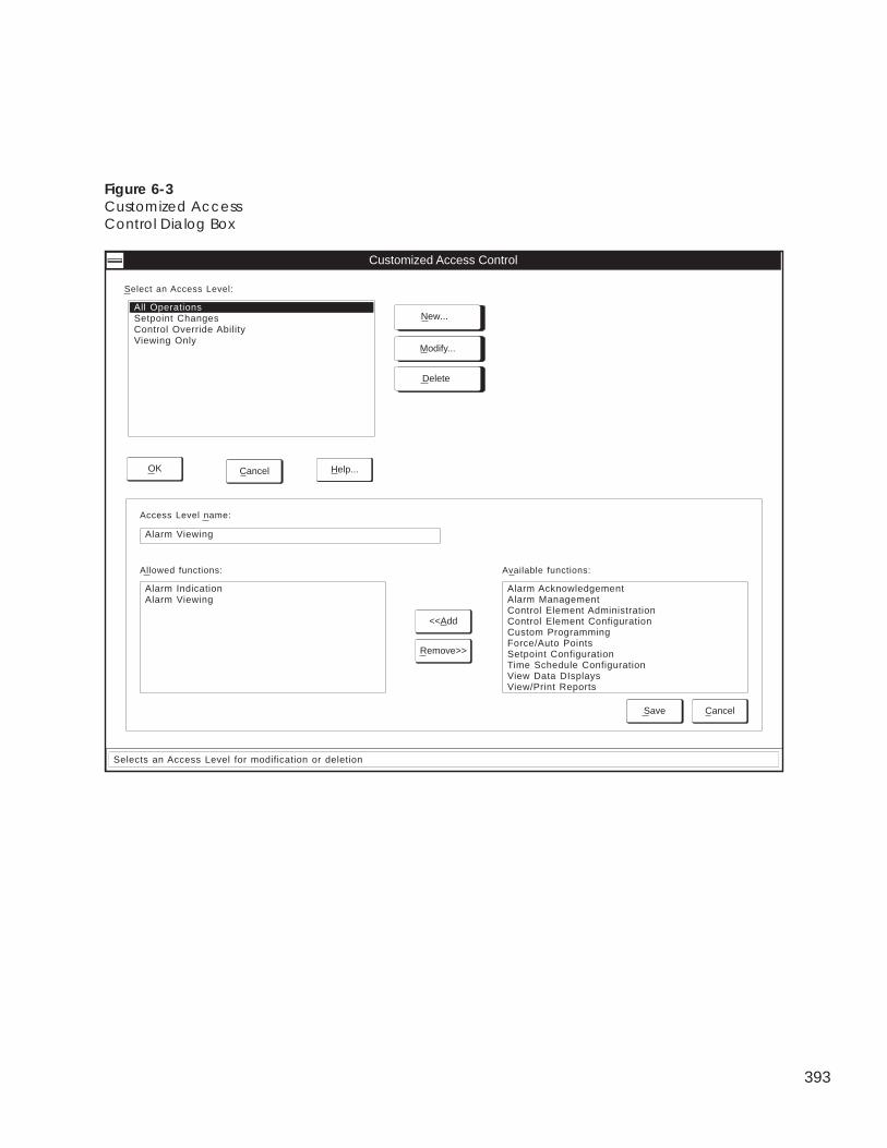
393
Figure 6-3Customized AccessControl Dialog Box
Customized Access Control
Allowed functions:
Alarm IndicationAlarm Viewing
Access Level name:
Alarm Viewing
Available functions:
Alarm AcknowledgementAlarm ManagementControl Element AdministrationControl Element ConfigurationCustom ProgrammingForce/Auto PointsSetpoint ConfigurationTime Schedule ConfigurationView Data DIsplaysView/Print Reports
<<Add
Remove>>
Save Cancel
Selects an Access Level for modification or deletion
Select an Access Level:
All OperationsSetpoint ChangesControl Override AbilityViewing Only
OK Help...Cancel
New...
Modify...
Delete
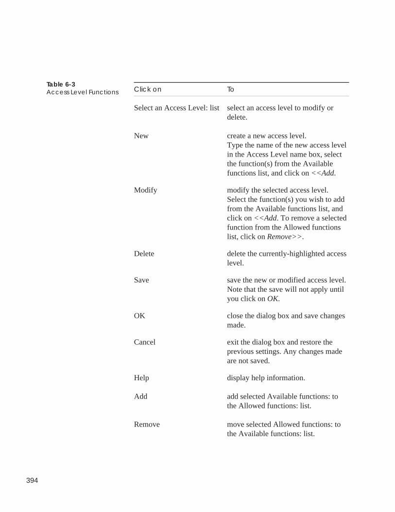
394
Click on To
Select an Access Level: list select an access level to modify ordelete.
New create a new access level.Type the name of the new access levelin the Access Level name box, selectthe function(s) from the Availablefunctions list, and click on <<Add.
Modify modify the selected access level.Select the function(s) you wish to addfrom the Available functions list, andclick on <<Add. To remove a selectedfunction from the Allowed functionslist, click on Remove>>.
Delete delete the currently-highlighted accesslevel.
Save save the new or modified access level.Note that the save will not apply untilyou click on OK.
OK close the dialog box and save changesmade.
Cancel exit the dialog box and restore theprevious settings. Any changes madeare not saved.
Help display help information.
Add add selected Available functions: tothe Allowed functions: list.
Remove move selected Allowed functions: tothe Available functions: list.
Table 6-3Access Level Functions
395
1. Click on New to create a new access level.
2. Type the name of the new access level in the Access LevelName box.
3. Select the functions to which this access level will be allowedfrom the Available functions list, and click on <<Add.
Note: Refer to Table 6-4 for a list of functions and theircorresponding ComfortVIEW operations.
The selected functions will display in the Allowed functionslist.
4. If you wish to remove a function from the Allowed functionslist, select the function and click on Remove>>.
5. When the Allowed functions list contains the desired func-tions for this access level, click on Save.
6. Click on OK to close the dialog box and save the new accesslevel.
1. Select the access level from the list displayed under Select anAccess Level:.
2. Do one of the following, depending on whether you want tomodify or delete an access level:
• To modify an access level’s associated functions, click onModify and then follow Steps 3 to 6 under To Create aNew Access Level.
• To delete an access level, click on Delete.
ComfortVIEW displays a dialog box asking for confirma-tion before deleting the selected access level. Click on Yesto delete the access level or click on No to prevent thedeletion from taking place.
To Create a NewAccess Level
To Modify or Delete anExisting Access Level
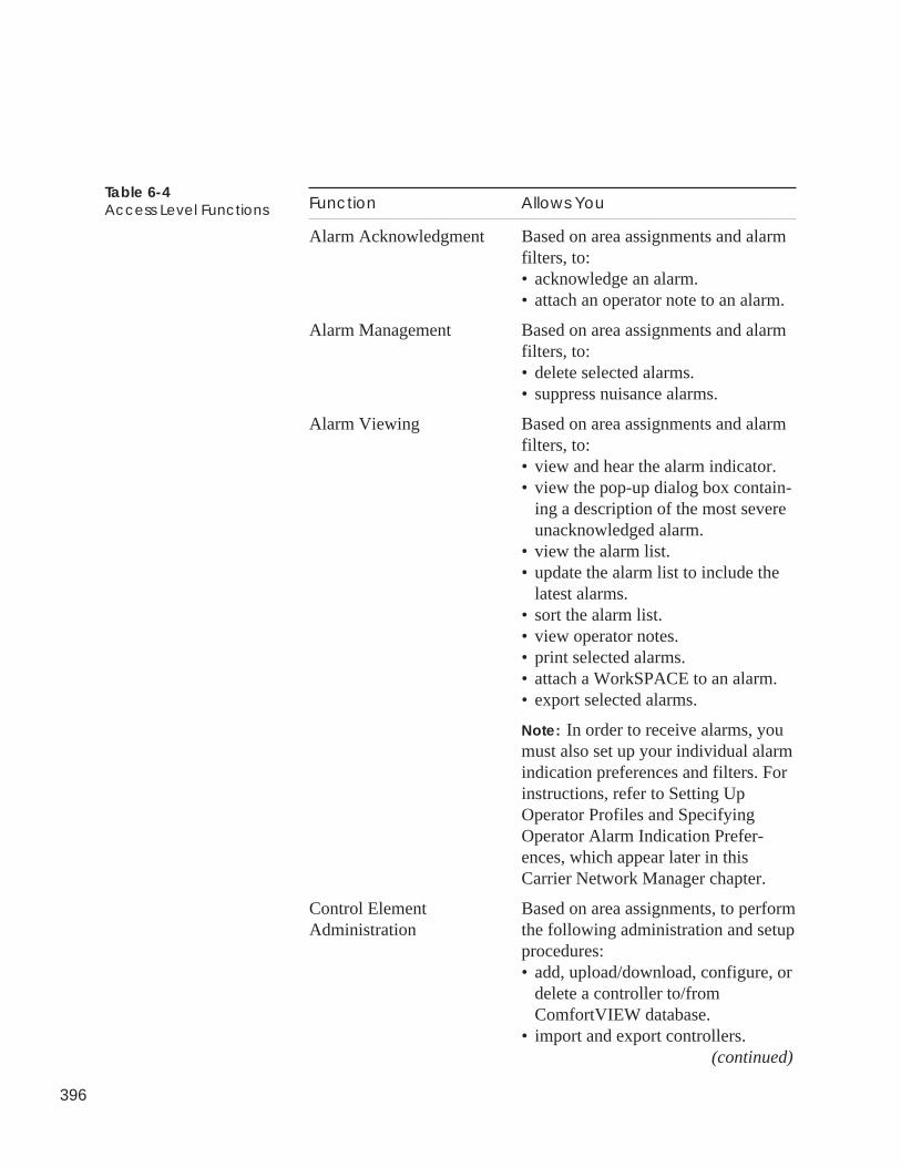
396
Function Allows You
Alarm Acknowledgment Based on area assignments and alarmfilters, to:• acknowledge an alarm.• attach an operator note to an alarm.
Alarm Management Based on area assignments and alarmfilters, to:• delete selected alarms.• suppress nuisance alarms.
Alarm Viewing Based on area assignments and alarmfilters, to:• view and hear the alarm indicator.• view the pop-up dialog box contain-
ing a description of the most severeunacknowledged alarm.
• view the alarm list.• update the alarm list to include the
latest alarms.• sort the alarm list.• view operator notes.• print selected alarms.• attach a WorkSPACE to an alarm.• export selected alarms.
Note: In order to receive alarms, youmust also set up your individual alarmindication preferences and filters. Forinstructions, refer to Setting UpOperator Profiles and SpecifyingOperator Alarm Indication Prefer-ences, which appear later in thisCarrier Network Manager chapter.
Control Element Based on area assignments, to performAdministration the following administration and setup
procedures:• add, upload/download, configure, or
delete a controller to/fromComfortVIEW database.
• import and export controllers. (continued)
Table 6-4Access Level Functions
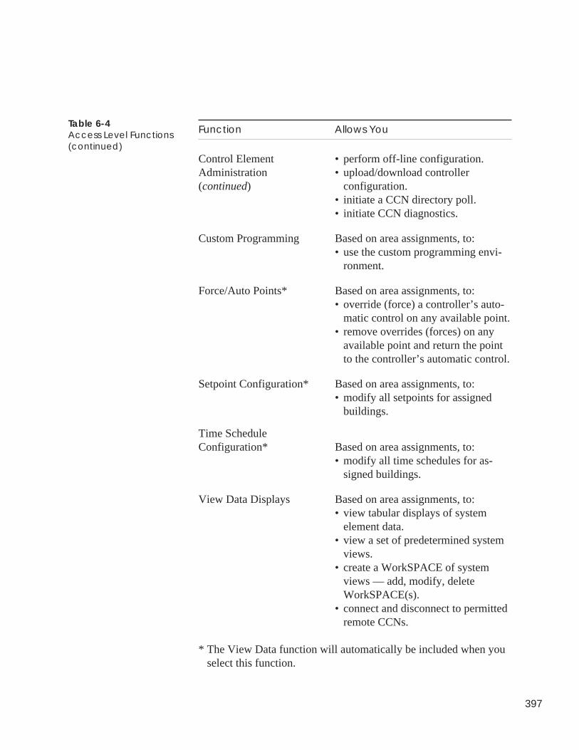
397
Function Allows You
Control Element • perform off-line configuration.Administration • upload/download controller(continued) configuration.
• initiate a CCN directory poll.• initiate CCN diagnostics.
Custom Programming Based on area assignments, to:• use the custom programming envi-
ronment.
Force/Auto Points* Based on area assignments, to:• override (force) a controller’s auto-
matic control on any available point.• remove overrides (forces) on any
available point and return the pointto the controller’s automatic control.
Setpoint Configuration* Based on area assignments, to:• modify all setpoints for assigned
buildings.
Time ScheduleConfiguration* Based on area assignments, to:
• modify all time schedules for as-signed buildings.
View Data Displays Based on area assignments, to:• view tabular displays of system
element data.• view a set of predetermined system
views.• create a WorkSPACE of system
views — add, modify, deleteWorkSPACE(s).
• connect and disconnect to permittedremote CCNs.
* The View Data function will automatically be included when youselect this function.
Table 6-4Access Level Functions(continued)
398
You must specify a login name, operator name, password, start-upapplication, access level, and alarm indication preferences for everyComfortVIEW operator.
Follow the steps below to create or modify any operator’s profile:
1. Display the Operator Configuration dialog box by clicking onthe Administration menu item followed by clicking on Opera-tors.
2. Click on New to add a new operator to the system, or
Click on Profile to modify the selected operator’s profileinformation.
ComfortVIEW displays the Operator Profile dialog box.
3. Refer to Figure 6-5 and Table 6-5 for instructions on usingthe Operator Profile dialog box.
After entering all information, click on OK.
If you are adding a new operator, the Operator Access dialogbox now displays. Refer to Assigning Access Levels toOperators for instructions on using this box.
If you are modifying an existing operator’s profile, the Opera-tor Configuration dialog box re-displays.
To create or modify your own operator profile:
1. Click on the Administration menu item.
2. Click on Your profile.
Note: You may also perform this command by clicking onthe Modify Your Operator Profile icon in thetoolbar.
Setting UpOperator Profiles
Setting Up Your OwnOperator Profile
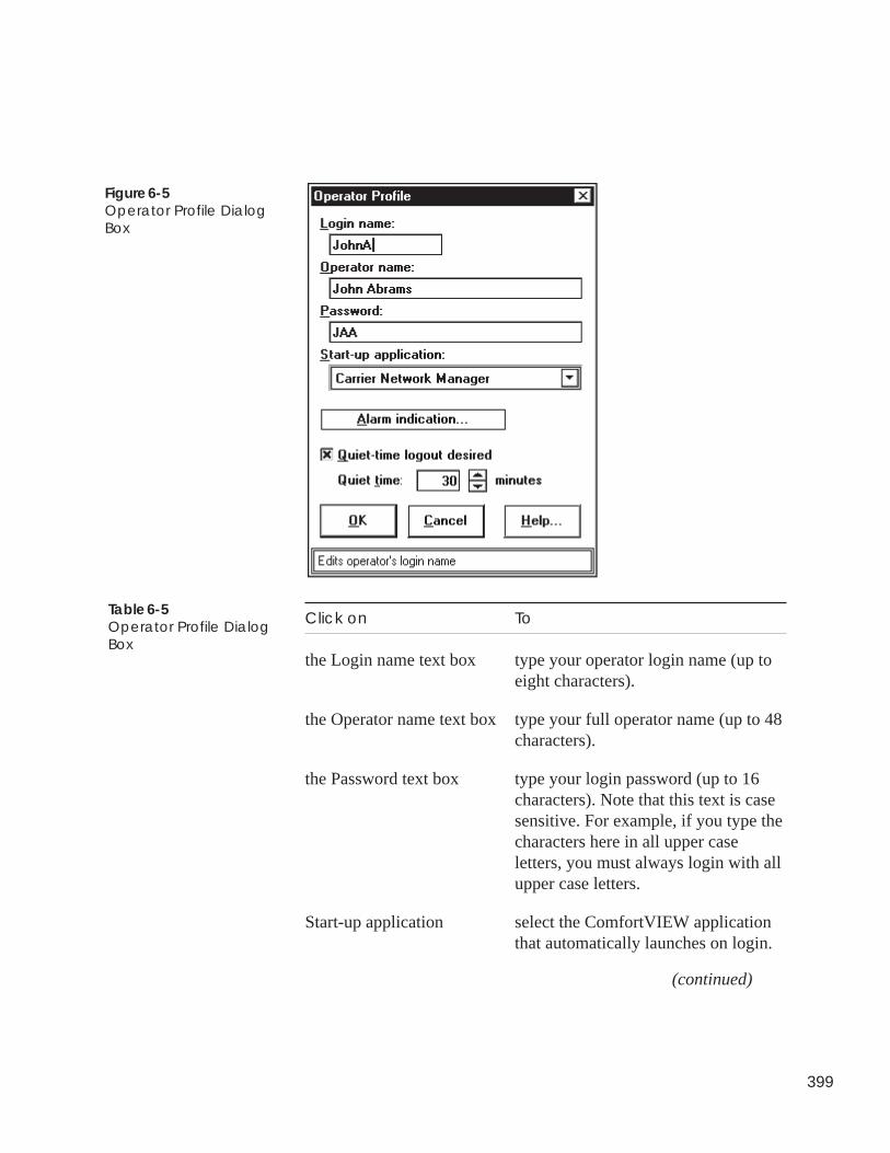
399
Click on To
the Login name text box type your operator login name (up toeight characters).
the Operator name text box type your full operator name (up to 48characters).
the Password text box type your login password (up to 16characters). Note that this text is casesensitive. For example, if you type thecharacters here in all upper caseletters, you must always login with allupper case letters.
Start-up application select the ComfortVIEW applicationthat automatically launches on login.
(continued)
Figure 6-5Operator Profile DialogBox
Table 6-5Operator Profile DialogBox
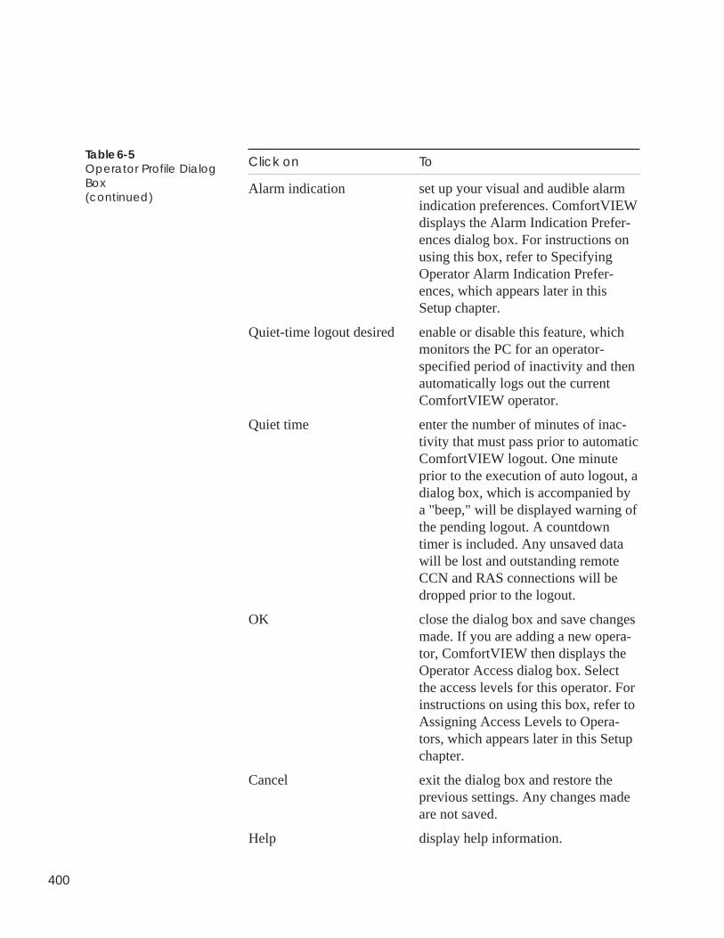
400
Click on To
Alarm indication set up your visual and audible alarmindication preferences. ComfortVIEWdisplays the Alarm Indication Prefer-ences dialog box. For instructions onusing this box, refer to SpecifyingOperator Alarm Indication Prefer-ences, which appears later in thisSetup chapter.
Quiet-time logout desired enable or disable this feature, whichmonitors the PC for an operator-specified period of inactivity and thenautomatically logs out the currentComfortVIEW operator.
Quiet time enter the number of minutes of inac-tivity that must pass prior to automaticComfortVIEW logout. One minuteprior to the execution of auto logout, adialog box, which is accompanied bya "beep," will be displayed warning ofthe pending logout. A countdowntimer is included. Any unsaved datawill be lost and outstanding remoteCCN and RAS connections will bedropped prior to the logout.
OK close the dialog box and save changesmade. If you are adding a new opera-tor, ComfortVIEW then displays theOperator Access dialog box. Selectthe access levels for this operator. Forinstructions on using this box, refer toAssigning Access Levels to Opera-tors, which appears later in this Setupchapter.
Cancel exit the dialog box and restore theprevious settings. Any changes madeare not saved.
Help display help information.
Table 6-5Operator Profile DialogBox(continued)
401
You must assign access or privilege levels to every ComfortVIEWoperator. You can assign access levels to operators on an area byarea basis. For example, if you have two access levels named Con-trol Element Configuration and Passive Monitor (each with differentaccess privileges), you could give an operator Control ElementConfiguration access for one area in your CCN, and Passive Moni-tor access for another area.
For information on creating access levels, refer to Defining SystemAccess Levels (which appears earlier in this chapter).
Follow the steps below to assign an operator’s access levels.
Note: If you are adding a new operator to the system, the Opera-tor Access dialog box automatically displays after youclick on the Operator Profile dialog box’s OK button. Skipto Step 3 below.
1. Display the Operator Configuration dialog box by clicking onthe Administration menu item followed by clicking on Opera-tors.
2. Click on Access levels to modify the selected operator’saccess levels.
ComfortVIEW displays the Operator Access dialog box.
3. Refer to Figure 6-6 and Table 6-6 for instructions on usingthis dialog box.
4. Click to enable or disable the following privileges: Systemsetup, Report setup, Report Generation, and Workspacesetup. Refer to Table 6-6 for a description of specific opera-tions associated with these privileges.
5. Select the operator’s default access level from the drop downlist box. The operator will by default be assigned this accesslevel for all areas with the exception of those areas listed inthe Exceptions list.
6. In the Exceptions Areas list, select the areas for which you wishto assign an access level that is different from the default accesslevel.
Assigning AccessLevels toOperators
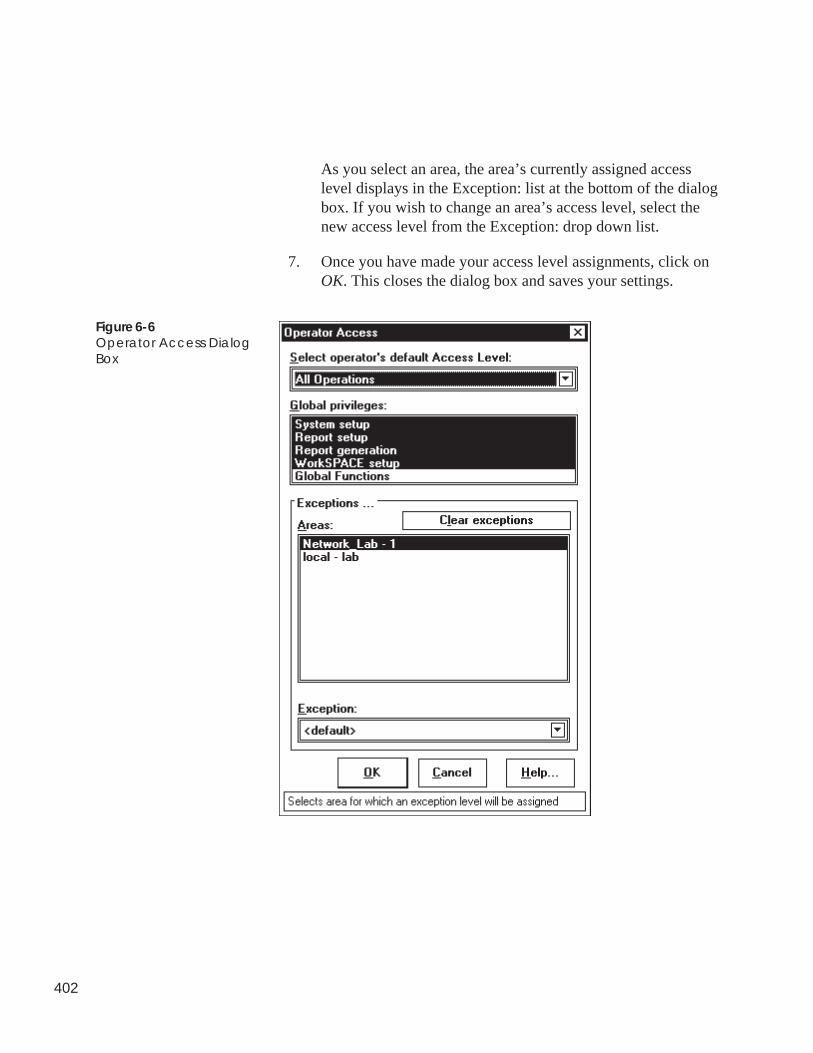
402
As you select an area, the area’s currently assigned accesslevel displays in the Exception: list at the bottom of the dialogbox. If you wish to change an area’s access level, select thenew access level from the Exception: drop down list.
7. Once you have made your access level assignments, click onOK. This closes the dialog box and saves your settings.
Figure 6-6Operator Access DialogBox
403
Click on To
Select operator’s defaultAccess Level: select the privilege level that the operator
will have for all areas in your CCN withthe exception of those areas listed in thisdialog box under Exceptions. Clicking onthe down arrow displays all existingaccess levels. Select an access level fromthis list.
Global Privileges:
System setup enable/disable system setup privileges.These privileges include access to thefollowing operations:
• operator configuration and preferences.For example, adding, modifying, anddeleting operators —name and pass-word assignments, quiet time for autologoff, access level creation, modifica-tion, and deletion, alarm annunciationand viewing criteria including settingup alarm filters.
• alarm administration.For example, creating custom alarmmessages, specifying alarm printingcriteria, WorkSPACE/alarm condi-tion relationships.
• ComfortVIEW Setup application.For example, alarm printer-locationand options, LAN computer names,global report data retrieval settings.
• CCN administration.For example, adding, modifying, anddeleting CCNs, areas, includingsetting PC address and baud rate,alarm acknowledgment capability.
(continued)
Table 6-6Operator Access DialogBox
404
Click on To
Report setup enable/disable report setup privileges.These privileges include access to thefollowing operations:
• creating report definitions.
• install optional and custom reports.
• configure reports that have customgroupings of data — consumable,runtime, history.
Report generation perform the following operations:
• generate, view, and print any report—standard, optional, or custom.
WorkSPACE setup enable/disable WorkSPACE setupprivileges. These privileges allow youto create and modify WorkSPACEsViewSPACES, and trends.
Global functions enable/disable access to the followingGlobal Function Manager operations:
• configure timed forces, central timeschedules, point transfers, and holidaytables.
the Exceptions Areas list select each area that you wish toassign a different access level than thedefault access level that is specified inthe Select operator’s default AccessLevel box. As you select an area, thearea’s currently-assigned access leveldisplays in the Exception: list at thebottom of the dialog box.
Initially, all areas are assigned to thedefault access level. If you wish tochange the access level, select the newaccess level for this area from theException: drop down list.
(continued)
Table 6-6Operator Access DialogBox(continued)
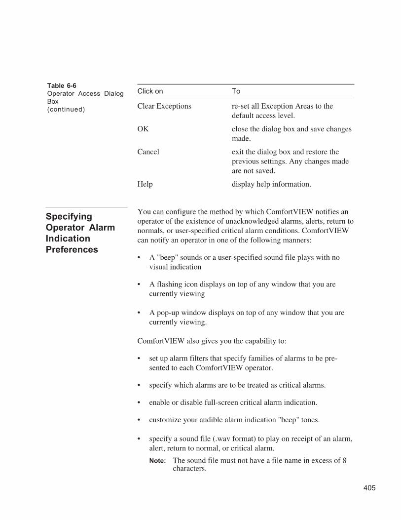
405
Click on To
Clear Exceptions re-set all Exception Areas to thedefault access level.
OK close the dialog box and save changesmade.
Cancel exit the dialog box and restore theprevious settings. Any changes madeare not saved.
Help display help information.
You can configure the method by which ComfortVIEW notifies anoperator of the existence of unacknowledged alarms, alerts, return tonormals, or user-specified critical alarm conditions. ComfortVIEWcan notify an operator in one of the following manners:
• A "beep" sounds or a user-specified sound file plays with novisual indication
• A flashing icon displays on top of any window that you arecurrently viewing
• A pop-up window displays on top of any window that you arecurrently viewing.
ComfortVIEW also gives you the capability to:
• set up alarm filters that specify families of alarms to be pre-sented to each ComfortVIEW operator.
• specify which alarms are to be treated as critical alarms.
• enable or disable full-screen critical alarm indication.
• customize your audible alarm indication "beep" tones.
• specify a sound file (.wav format) to play on receipt of an alarm,alert, return to normal, or critical alarm.
Note: The sound file must not have a file name in excess of 8characters.
Table 6-6
Operator Access Dialog
Box
(continued)
Specifying
Operator Alarm
Indication
Preferences
406
Follow the steps below to set up or modify operator alarm indicationpreferences:
1. Display the Operator Configuration dialog box by clicking onthe Administration menu item followed by clicking on Opera-tors.
2. Select the operator whose preferences you wish to access.
3. Click on Profile.
4. Click on Alarm indication.
ComfortVIEW displays the Alarm Indication Preferencesdialog box.
5. Specify visual and audible alarm indication preferences, orclick on Defaults to select the pre-programmed default op-tions.
Refer to Figure 6-7 and Table 6-7 for instructions on usingthis dialog box.
6. Once you have specified alarm indication preferences, clickon OK. This closes the dialog box and saves the settings.
Note: ComfortVIEW includes a new feature that gives you theability to override this audible indication and play aspecified .wav file on the occurrence of specific alarmsfrom specific system elements and points. For moreinformation on this feature, refer to Assigning CustomMessages to Incoming Alarms in the Alarm Managerchapter of this manual.
To create or modify your own current alarm indication preferences:
1. Click on the Administration menu item.
2. Click on Your profile.
Note: You may also perform this command by clicking onthe Modify Your Operator Profile icon in thetoolbar. You cannot, however, modify alarm filterswhen you are modifying from Your Profile.
Specifying Your OwnAlarm IndicationPreferences
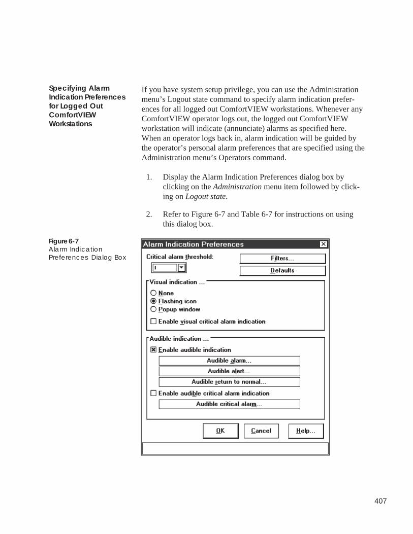
407
If you have system setup privilege, you can use the Administrationmenu’s Logout state command to specify alarm indication prefer-ences for all logged out ComfortVIEW workstations. Whenever anyComfortVIEW operator logs out, the logged out ComfortVIEWworkstation will indicate (annunciate) alarms as specified here.When an operator logs back in, alarm indication will be guided bythe operator’s personal alarm preferences that are specified using theAdministration menu’s Operators command.
1. Display the Alarm Indication Preferences dialog box byclicking on the Administration menu item followed by click-ing on Logout state.
2. Refer to Figure 6-7 and Table 6-7 for instructions on usingthis dialog box.
Figure 6-7Alarm IndicationPreferences Dialog Box
Specifying AlarmIndication Preferencesfor Logged OutComfortVIEWWorkstations
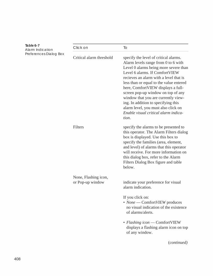
408
Click on To
Critical alarm threshold specify the level of critical alarms.Alarm levels range from 0 to 6 withLevel 0 alarms being more severe thanLevel 6 alarms. If ComfortVIEWrecieves an alarm with a level that isless than or equal to the value enteredhere, ComfortVIEW displays a full-screen pop-up window on top of anywindow that you are currently view-ing. In addition to specifying thisalarm level, you must also click onEnable visual critical alarm indica-tion.
Filters specify the alarms to be presented tothis operator. The Alarm Filters dialogbox is displayed. Use this box tospecify the families (area, element,and level) of alarms that this operatorwill receive. For more information onthis dialog box, refer to the AlarmFilters Dialog Box figure and tablebelow.
None, Flashing icon,or Pop-up window indicate your preference for visual
alarm indication.
If you click on:• None — ComfortVIEW produces
no visual indication of the existenceof alarms/alerts.
• Flashing icon — ComfortVIEWdisplays a flashing alarm icon on topof any window.
(continued)
Table 6-7Alarm IndicationPreferences Dialog Box
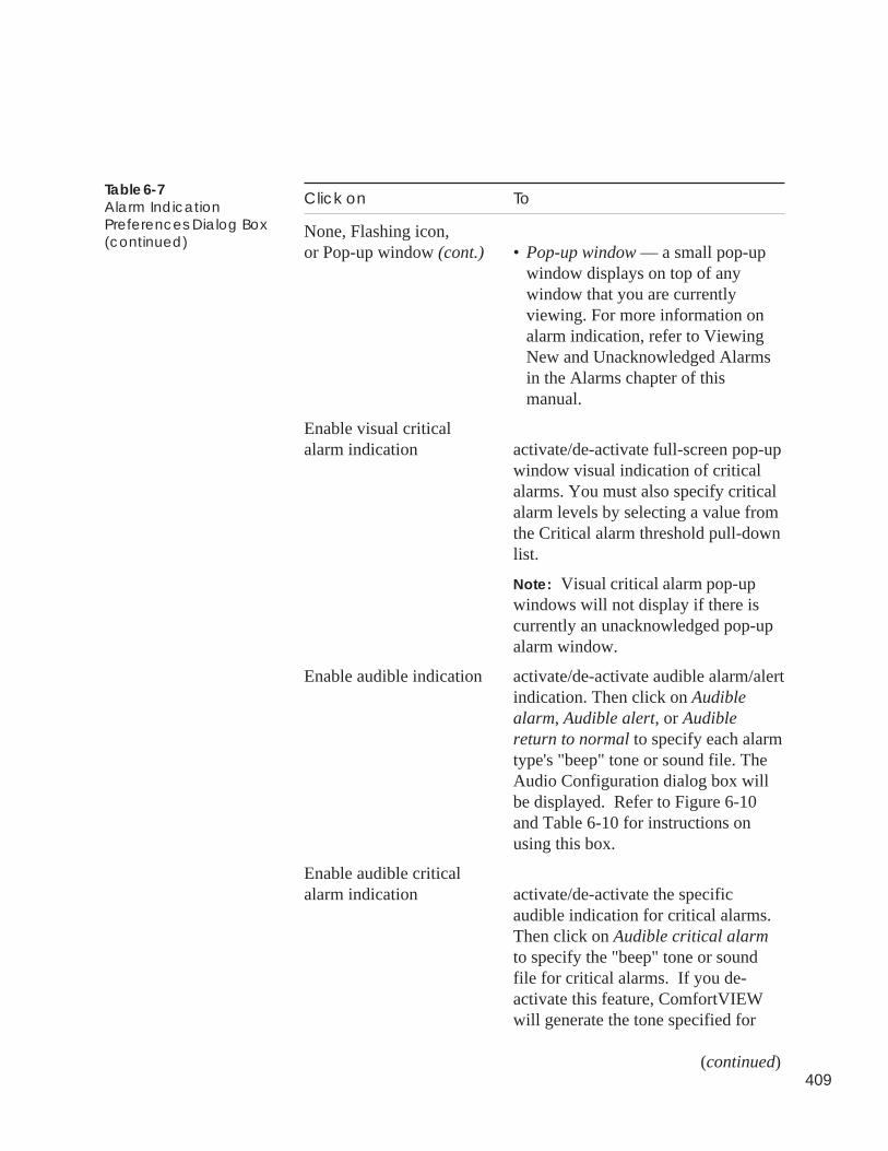
409
Click on To
None, Flashing icon,or Pop-up window (cont.) • Pop-up window — a small pop-up
window displays on top of anywindow that you are currentlyviewing. For more information onalarm indication, refer to ViewingNew and Unacknowledged Alarmsin the Alarms chapter of thismanual.
Enable visual criticalalarm indication activate/de-activate full-screen pop-up
window visual indication of criticalalarms. You must also specify criticalalarm levels by selecting a value fromthe Critical alarm threshold pull-downlist.
Note: Visual critical alarm pop-upwindows will not display if there iscurrently an unacknowledged pop-upalarm window.
Enable audible indication activate/de-activate audible alarm/alertindication. Then click on Audiblealarm, Audible alert, or Audiblereturn to normal to specify each alarmtype's "beep" tone or sound file. TheAudio Configuration dialog box willbe displayed. Refer to Figure 6-10and Table 6-10 for instructions onusing this box.
Enable audible criticalalarm indication activate/de-activate the specific
audible indication for critical alarms.Then click on Audible critical alarmto specify the "beep" tone or soundfile for critical alarms. If you de-activate this feature, ComfortVIEWwill generate the tone specified for
(continued)
Table 6-7Alarm IndicationPreferences Dialog Box(continued)
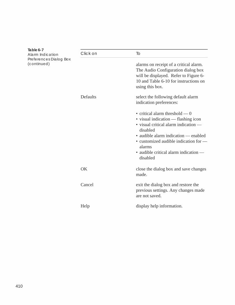
410
Click on To
alarms on receipt of a critical alarm.The Audio Configuration dialog boxwill be displayed. Refer to Figure 6-10 and Table 6-10 for instructions onusing this box.
Defaults select the following default alarmindication preferences:
• critical alarm threshold — 0• visual indication — flashing icon• visual critical alarm indication —
disabled• audible alarm indication — enabled• customized audible indication for —
alarms• audible critical alarm indication —
disabled
OK close the dialog box and save changesmade.
Cancel exit the dialog box and restore theprevious settings. Any changes madeare not saved.
Help display help information.
Table 6-7Alarm IndicationPreferences Dialog Box(continued)
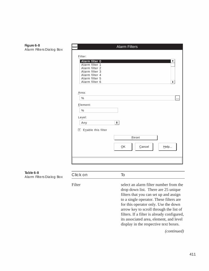
411
Click on To
Filter select an alarm filter number from thedrop down list. There are 25 uniquefilters that you can set up and assignto a single operator. These filters arefor this operator only. Use the downarrow key to scroll through the list offilters. If a filter is already configured,its associated area, element, and leveldisplay in the respective text boxes.
(continued)
Figure 6-8Alarm Filters Dialog Box
Table 6-8Alarm Filters Dialog Box
Alarm Filters
Level:
Area:
OK Cancel Help...
Any
Element:
%
Reset
Filter:
Enable this filter
X
Alarm filter 0Alarm filter 0Alarm filter 1Alarm filter 2Alarm filter 3Alarm filter 4Alarm filter 5Alarm filter 6
% ...
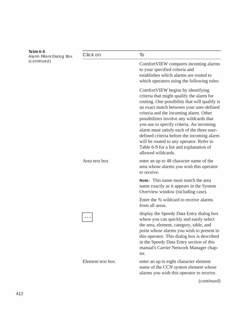
412
Table 6-8Alarm Filters Dialog Box(continued)
Click on To
ComfortVIEW compares incoming alarmsto your specified criteria andestablishes which alarms are routed towhich operators using the following rules:
ComfortVIEW begins by identifyingcriteria that might qualify the alarm forrouting. One possibility that will qualify isan exact match between your user-definedcriteria and the incoming alarm. Otherpossibilities involve any wildcards thatyou use to specify criteria. An incomingalarm must satisfy each of the three user-defined criteria before the incoming alarmwill be routed to any operator. Refer toTable 6-9 for a list and explanation ofallowed wildcards.
Area text box enter an up to 48 character name of thearea whose alarms you wish this operatorto receive.
Note: This name must match the areaname exactly as it appears in the SystemOverview window (including case).
Enter the % wildcard to receive alarmsfrom all areas.
display the Speedy Data Entry dialog boxwhere you can quickly and easily selectthe area, element, category, table, andpoint whose alarms you wish to present tothis operator. This dialog box is describedin the Speedy Data Entry section of thismanual's Carrier Network Manager chap-ter.
Element text box enter an up to eight character elementname of the CCN system element whosealarms you wish this operator to receive.
(continued)
. . .
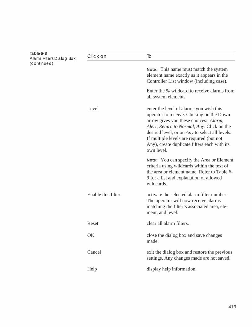
413
Click on To
Note: This name must match the systemelement name exactly as it appears in theController List window (including case).
Enter the % wildcard to receive alarms fromall system elements.
Level enter the level of alarms you wish thisoperator to receive. Clicking on the Downarrow gives you these choices: Alarm,Alert, Return to Normal, Any. Click on thedesired level, or on Any to select all levels.If multiple levels are required (but notAny), create duplicate filters each with itsown level.
Note: You can specify the Area or Elementcriteria using wildcards within the text ofthe area or element name. Refer to Table 6-9 for a list and explanation of allowedwildcards.
Enable this filter activate the selected alarm filter number.The operator will now receive alarmsmatching the filter’s associated area, ele-ment, and level.
Reset clear all alarm filters.
OK close the dialog box and save changesmade.
Cancel exit the dialog box and restore the previoussettings. Any changes made are not saved.
Help display help information.
Table 6-8Alarm Filters Dialog Box(continued)
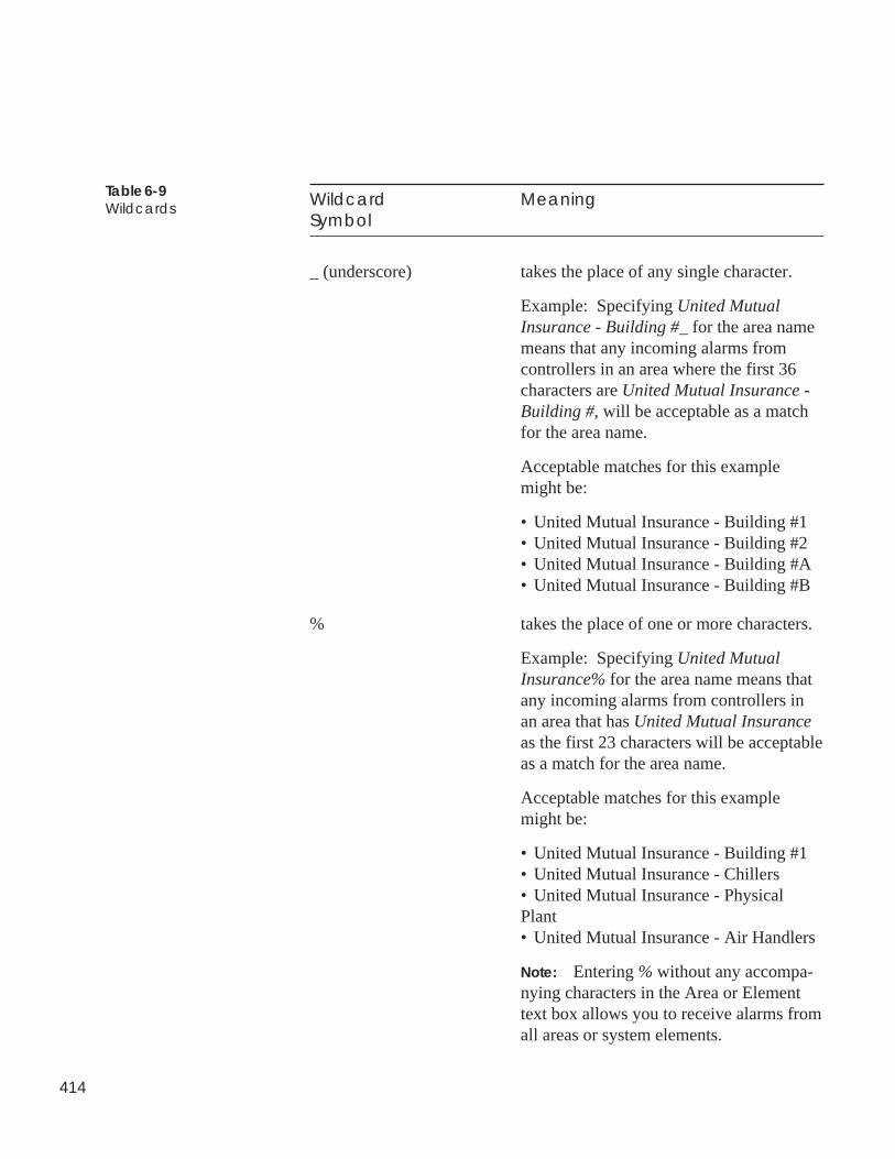
414
Wildcard MeaningSymbol
_ (underscore) takes the place of any single character.
Example: Specifying United MutualInsurance - Building #_ for the area namemeans that any incoming alarms fromcontrollers in an area where the first 36characters are United Mutual Insurance -Building #, will be acceptable as a matchfor the area name.
Acceptable matches for this examplemight be:
• United Mutual Insurance - Building #1• United Mutual Insurance - Building #2• United Mutual Insurance - Building #A• United Mutual Insurance - Building #B
% takes the place of one or more characters.
Example: Specifying United MutualInsurance% for the area name means thatany incoming alarms from controllers inan area that has United Mutual Insuranceas the first 23 characters will be acceptableas a match for the area name.
Acceptable matches for this examplemight be:
• United Mutual Insurance - Building #1• United Mutual Insurance - Chillers• United Mutual Insurance - PhysicalPlant• United Mutual Insurance - Air Handlers
Note: Entering % without any accompa-nying characters in the Area or Elementtext box allows you to receive alarms fromall areas or system elements.
Table 6-9Wildcards
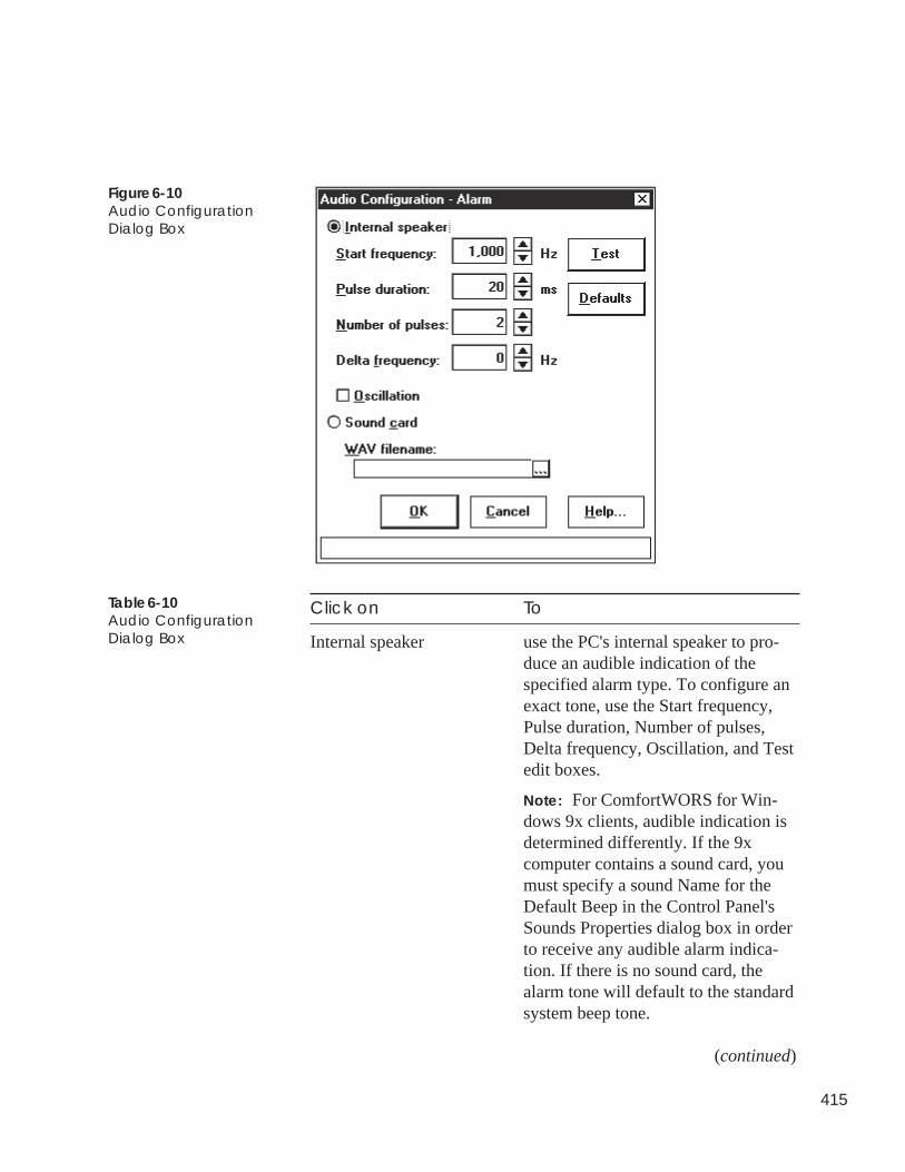
415
Figure 6-10Audio ConfigurationDialog Box
Table 6-10Audio ConfigurationDialog Box
Click on To
Internal speaker use the PC's internal speaker to pro-duce an audible indication of thespecified alarm type. To configure anexact tone, use the Start frequency,Pulse duration, Number of pulses,Delta frequency, Oscillation, and Testedit boxes.
Note: For ComfortWORS for Win-dows 9x clients, audible indication isdetermined differently. If the 9xcomputer contains a sound card, youmust specify a sound Name for theDefault Beep in the Control Panel'sSounds Properties dialog box in orderto receive any audible alarm indica-tion. If there is no sound card, thealarm tone will default to the standardsystem beep tone.
(continued)
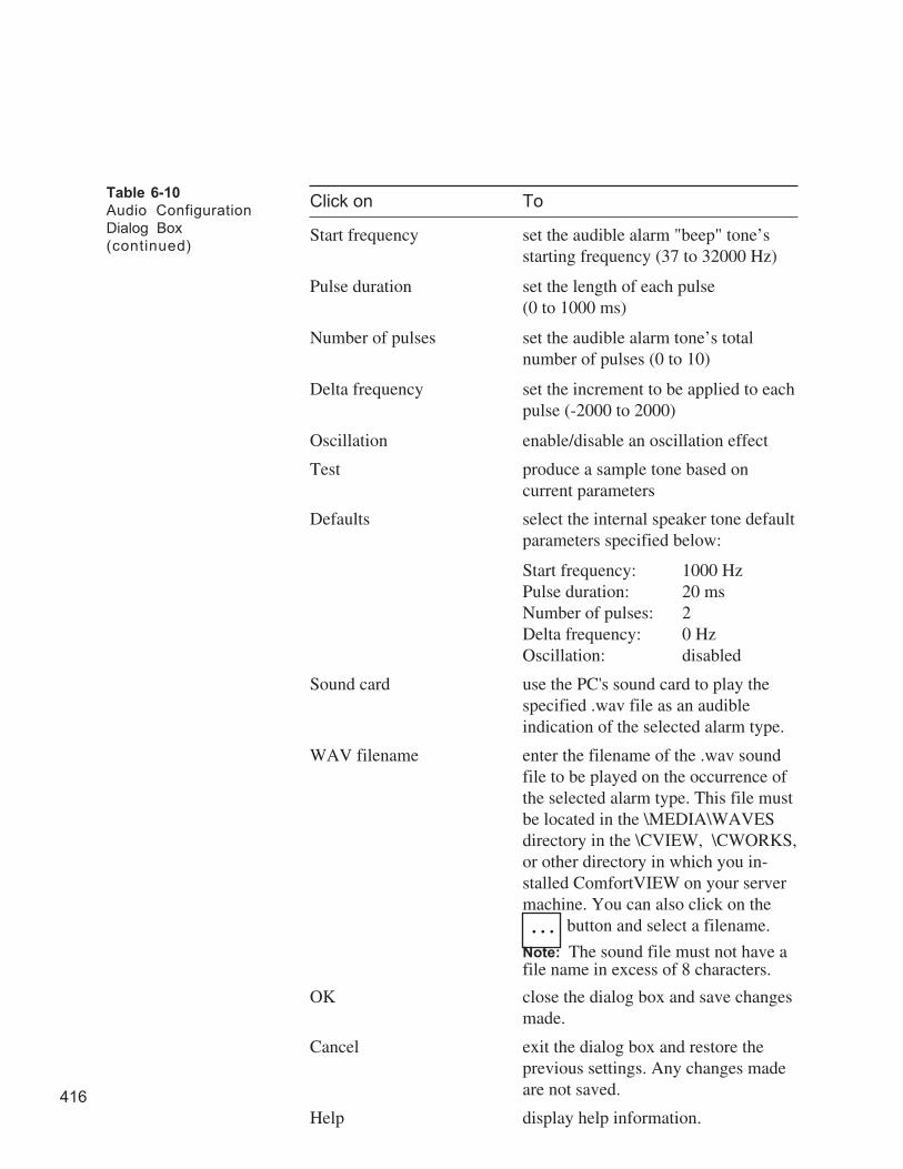
416
Click on To
Start frequency set the audible alarm "beep" tone’sstarting frequency (37 to 32000 Hz)
Pulse duration set the length of each pulse(0 to 1000 ms)
Number of pulses set the audible alarm tone’s totalnumber of pulses (0 to 10)
Delta frequency set the increment to be applied to eachpulse (-2000 to 2000)
Oscillation enable/disable an oscillation effect
Test produce a sample tone based oncurrent parameters
Defaults select the internal speaker tone defaultparameters specified below:
Start frequency: 1000 HzPulse duration: 20 msNumber of pulses: 2Delta frequency: 0 HzOscillation: disabled
Sound card use the PC's sound card to play thespecified .wav file as an audibleindication of the selected alarm type.
WAV filename enter the filename of the .wav soundfile to be played on the occurrence ofthe selected alarm type. This file mustbe located in the \MEDIA\WAVESdirectory in the \CVIEW, \CWORKS,or other directory in which you in-stalled ComfortVIEW on your servermachine. You can also click on the
button and select a filename.
Note: The sound file must not have afile name in excess of 8 characters.
OK close the dialog box and save changesmade.
Cancel exit the dialog box and restore theprevious settings. Any changes madeare not saved.
Help display help information.
Table 6-10
Audio Configuration
Dialog Box
(continued)
. . .
417
Specifying AlarmPrinters
ComfortVIEW gives you the capability to define families of alarmsthat will be automatically printed to specific ComfortVIEW printers.You define alarm families by setting up alarm filters that specify theArea, Element, and Level for incoming alarms. You then assignalarm filters to specific printers. The alarms will print on occurrenceto the specified printer(s).
ComfortVIEW compares incoming alarms to your specified criteriaand establishes which alarms get routed to which printers using thefollowing rules: ComfortVIEW begins by identifying criteria thatmight qualify the alarm for routing. One possibility that will qualifyis an exact match between your user-defined criteria and the incom-ing alarm. Other possibilities involve any wildcards that you use tospecify criteria. An incoming alarm must satisfy each of the threeuser-defined criteria before the incoming alarm will be routed to anyprinter. Refer to Table 6-9 for a list and explanation of allowedwildcards.
Follow the steps below to set up alarm filters and assign filters toprinters:
1. Click on the Administration menu item and then click onAlarm printers.
ComfortVIEW displays the Alarm Printers dialog box. Thenames of all ComfortVIEW printers, the computer name, andprinter port that controls the printer display under Select aprinter. You add printers to this list using ComfortVIEWSetup application.
2. Select a printer from the Select a Printer: box, and then clickon Filters.
ComfortVIEW displays the Alarms Filters dialog box.
3. You must now select an alarm filter number from the Filterdrop down list. There are 25 unique filters that you can set upand assign to a single printer. Select this field and then usethe down arrow key to scroll through the list of existingfilters.
If a filter is already configured, its associated area, element,and level criteria display in the respective text boxes.
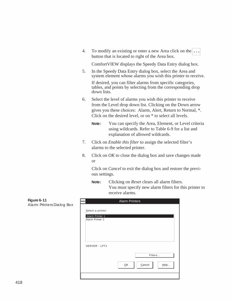
418
4. To modify an existing or enter a new Area click on the . . .button that is located to right of the Area box.
ComfortVIEW displays the Speedy Data Entry dialog box.
5. In the Speedy Data Entry dialog box, select the Area andsystem element whose alarms you wish this printer to receive.
If desired, you can filter alarms from specific categories,tables, and points by selecting from the corresponding dropdown lists.
6. Select the level of alarms you wish this printer to receivefrom the Level drop down list. Clicking on the Down arrowgives you these choices: Alarm, Alert, Return to Normal, *.Click on the desired level, or on * to select all levels.
Note: You can specify the Area, Element, or Level criteriausing wildcards. Refer to Table 6-9 for a list andexplanation of allowed wildcards.
7. Click on Enable this filter to assign the selected filter’salarms to the selected printer.
8. Click on OK to close the dialog box and save changes madeor
Click on Cancel to exit the dialog box and restore the previ-ous settings.
Note: Clicking on Reset clears all alarm filters.You must specify new alarm filters for this printer toreceive alarms.
Figure 6-11Alarm Printers Dialog Box
OK Cancel Help...
Alarm Printer 1
Alarm Printers
Select a printer:
SERVER - LPT1
Filters...
Alarm Printer 2
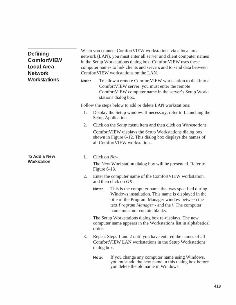
419
DefiningComfortVIEWLocal AreaNetworkWorkstations
When you connect ComfortVIEW workstations via a local areanetwork (LAN), you must enter all server and client computer namesin the Setup Workstations dialog box. ComfortVIEW uses thesecomputer names to link clients and servers and to send data betweenComfortVIEW workstations on the LAN.
Note: To allow a remote ComfortVIEW workstation to dial into aComfortVIEW server, you must enter the remoteComfortVIEW computer name in the server’s Setup Work-stations dialog box.
Follow the steps below to add or delete LAN workstations:
1. Display the Setup window. If necessary, refer to Launching theSetup Application.
2. Click on the Setup menu item and then click on Workstations.
ComfortVIEW displays the Setup Workstations dialog boxshown in Figure 6-12. This dialog box displays the names ofall ComfortVIEW workstations.
1. Click on New.
The New Workstation dialog box will be presented. Refer toFigure 6-13.
2. Enter the computer name of the ComfortVIEW workstation,and then click on OK.
Note: This is the computer name that was specified duringWindows installation. This name is displayed in thetitle of the Program Manager window between thetext Program Manager - and the \. The computername must not contain blanks.
The Setup Workstations dialog box re-displays. The newcomputer name appears in the Workstations list in alphabeticalorder.
3. Repeat Steps 1 and 2 until you have entered the names of allComfortVIEW LAN workstations in the Setup Workstationsdialog box.
Note: If you change any computer name using Windows,you must add the new name in this dialog box beforeyou delete the old name in Windows.
To Add a NewWorkstation
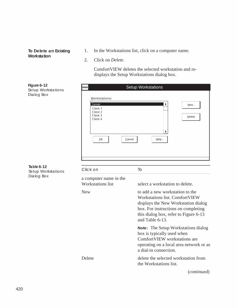
420
1. In the Workstations list, click on a computer name.
2. Click on Delete.
ComfortVIEW deletes the selected workstation and re-displays the Setup Workstations dialog box.
Figure 6-12Setup WorkstationsDialog Box
Setup Workstations
Server
Workstations:
Client 1Client 2Client 3Client 4
New...
Delete
Help...CancelOK
Click on To
a computer name in theWorkstations list select a workstation to delete.
New to add a new workstation to theWorkstations list. ComfortVIEWdisplays the New Workstation dialogbox. For instructions on completingthis dialog box, refer to Figure 6-13and Table 6-13.
Note: The Setup Workstations dialogbox is typically used whenComfortVIEW workstations areoperating on a local area network or asa dial-in connection.
Delete delete the selected workstation fromthe Workstations list.
(continued)
Table 6-12Setup WorkstationsDialog Box
To Delete an ExistingWorkstation
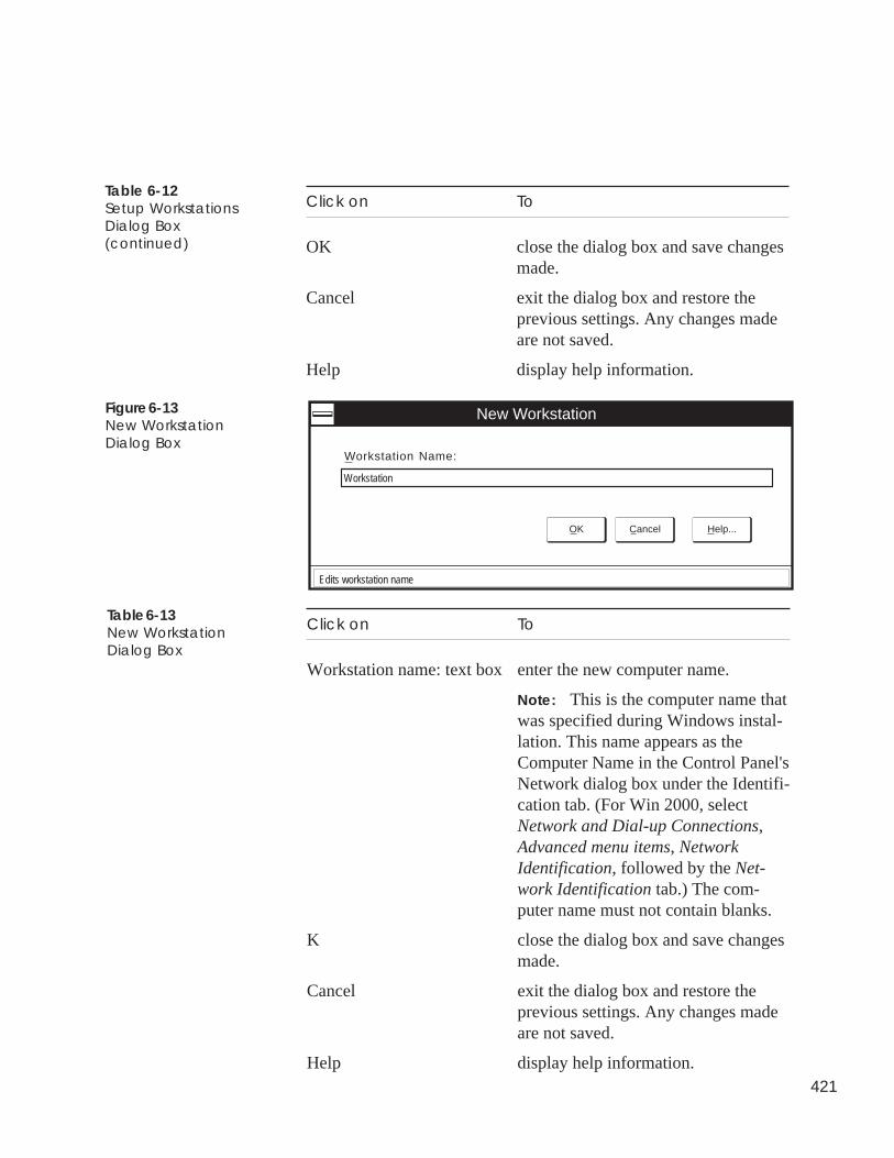
421
Click on To
OK close the dialog box and save changesmade.
Cancel exit the dialog box and restore theprevious settings. Any changes madeare not saved.
Help display help information.
Table 6-12Setup WorkstationsDialog Box(continued)
New Workstation
OK Cancel Help...
Workstation Name:
Workstation
Edits workstation name
Figure 6-13New WorkstationDialog Box
Table 6-13New WorkstationDialog Box
Click on To
Workstation name: text box enter the new computer name.
Note: This is the computer name thatwas specified during Windows instal-lation. This name appears as theComputer Name in the Control Panel'sNetwork dialog box under the Identifi-cation tab. (For Win 2000, selectNetwork and Dial-up Connections,Advanced menu items, NetworkIdentification, followed by the Net-work Identification tab.) The com-puter name must not contain blanks.
K close the dialog box and save changesmade.
Cancel exit the dialog box and restore theprevious settings. Any changes madeare not saved.
Help display help information.
422
DefiningComfortVIEWAlarm PrinterNames and PortLocations
ComfortVIEW gives you the capability to define families of alarms thatwill be routed to specific printers. You define the families using theCarrier Network Manager application.
Follow the steps below to specify ComfortVIEW alarm printers. Theseare the printer names that will appear in the Alarm Printers dialog boxthat displays when you click on the Carrier Network Manager’s Adminis-tration menu item and the Alarm Printers command.
1. Display the Setup window. If necessary, refer to Launching theSetup Application.
2. Click on the Setup menu item and then click on Alarm Printers.
ComfortVIEW displays the Setup Alarm Printers dialog boxshown in Figure 6-14. This dialog box displays the names of allalarm printers.
1. Click on New.
The New Printer dialog box will be presented. Refer to Figure 6-15.
2. Enter a name for the alarm printer.
3. Click on the Port: drop down list and select the computer and portto which the printer is connected. If your ComfortVIEW worksta-tions are connected via a local area network (LAN), the Port listwill include all active ports on your Windows NT network. If youare not on a LAN, the list will include all active ports on yourcomputer.
4. Click on OK to save the data, or on Cancel to exit without savingchanges.
The Setup Printers dialog box re-displays. The new printer nameappears in the Printers list in alphabetical order.
5. Repeat Steps 1 to 4 until the Setup Printers dialog box includes thenames of all ComfortVIEW alarm printers.
You now must use the Alarm Printers command in the Setupapplication’s Administration Menu to assign alarms to specificComfortVIEW printers.
To Add a New Printer
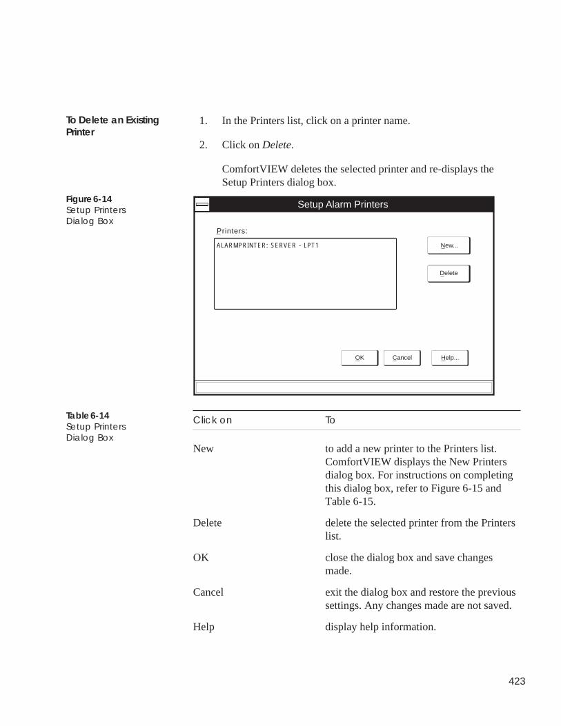
423
1. In the Printers list, click on a printer name.
2. Click on Delete.
ComfortVIEW deletes the selected printer and re-displays theSetup Printers dialog box.
Click on To
New to add a new printer to the Printers list.ComfortVIEW displays the New Printersdialog box. For instructions on completingthis dialog box, refer to Figure 6-15 andTable 6-15.
Delete delete the selected printer from the Printerslist.
OK close the dialog box and save changesmade.
Cancel exit the dialog box and restore the previoussettings. Any changes made are not saved.
Help display help information.
To Delete an ExistingPrinter
Figure 6-14Setup PrintersDialog Box
Table 6-14Setup PrintersDialog Box
Setup Alarm Printers
OK Cancel Help...
ControlRoom
Printers:
ALARMPRINTER: SERVER - LPT1 New...
Delete
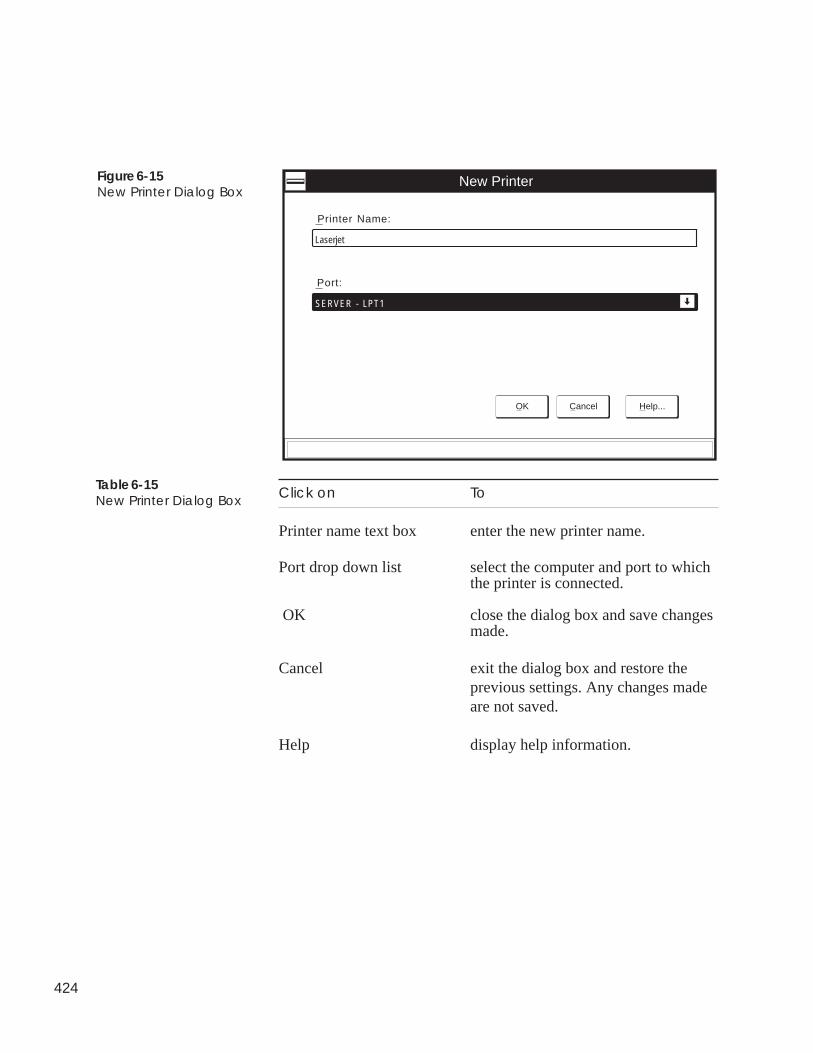
424
Figure 6-15New Printer Dialog Box
New Printer
OK Cancel Help...
Printer Name:
Laserjet
Port:
SERVER - LPT1
Table 6-15New Printer Dialog Box Click on To
Printer name text box enter the new printer name.
Port drop down list select the computer and port to whichthe printer is connected.
OK close the dialog box and save changesmade.
Cancel exit the dialog box and restore theprevious settings. Any changes madeare not saved.
Help display help information.
425
Follow the steps below to define custom analog and discrete engi-neering units. These units will display along with points in FIDs andComfort Controllers.
1. Display the Setup window. If necessary, refer to Launchingthe Setup Application.
2. Click on the Setup menu item and then click on Custom units.
ComfortVIEW displays the Custom Units/Discrete Statesdialog box. Refer to Table 6-16 and Figure 6-16.
3. Follow the Defining Discrete States and the Defining AnalogStates instructions below. Then click on OK to exit the dialogbox and save your changes.
To assign the custom engineering units to FID points, enter thenumber that corresponds to the desired engineering unit in theDisplay Units decision that appears in the FID's service configura-tion table. For an explanation of this decision, refer to the UT203FID Overview and Configuration Manual.
To assign custom engineering units to Comfort Controller points,select the desired engineering unit from the sensor type/units/statedrop down list that appears in the Carrier Network Manager'sObject Definition dialog box. Note that when using the BuildingSupervisor, the Network Service Tool, or another interface device toview Comfort Controller points that have been assigned customunits, the units will appear blank.
In the left discrete states column, enter the state that signifies anopen contact. In the right discrete states column, enter the state thatsignifies a closed contact.
Note: For DI devices, it is assumed that the FID's SensedDiscrete Logic Type decision is set to StandardLogic. For DO devices, this assumes that the OutputSignal decision is set to Straight Logic.
In the Analog units text box, enter the name for the analog unit.
Defining CustomEngineering Units
Defining Analog Units
Defining Discrete States
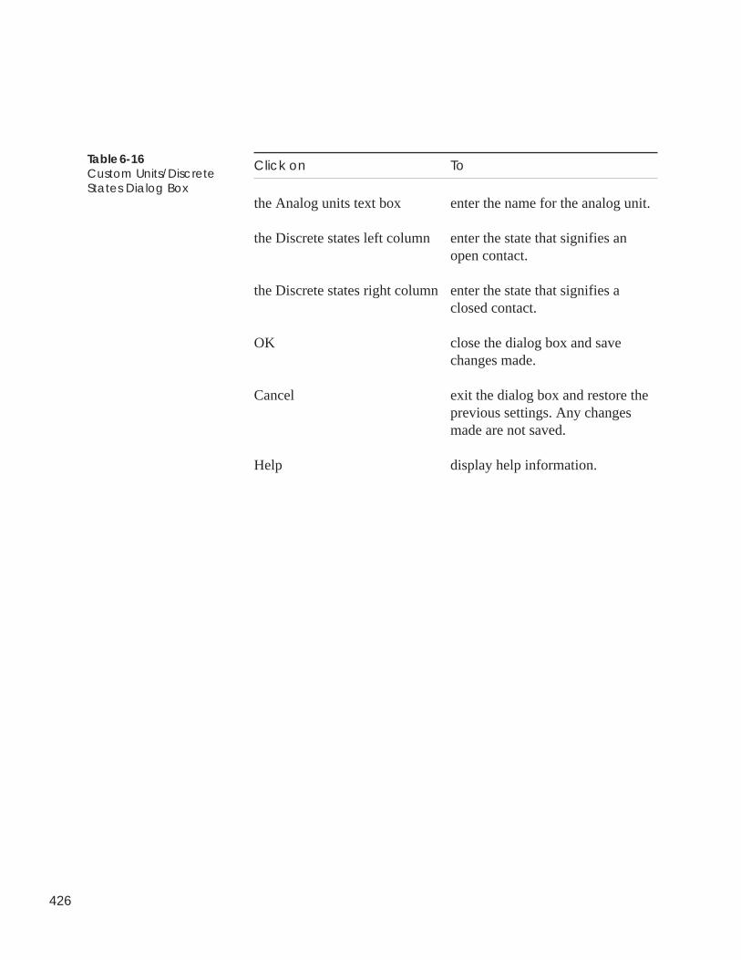
426
Click on To
the Analog units text box enter the name for the analog unit.
the Discrete states left column enter the state that signifies anopen contact.
the Discrete states right column enter the state that signifies aclosed contact.
OK close the dialog box and savechanges made.
Cancel exit the dialog box and restore theprevious settings. Any changesmade are not saved.
Help display help information.
Table 6-16Custom Units/DiscreteStates Dialog Box
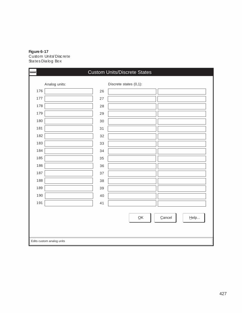
427
Figure 6-17Custom Units/DiscreteStates Dialog Box
Custom Units/Discrete States
OK Cancel Help...
Analog units:
Edits custom analog units
Discrete states (0,1):
176
177
178
179
180
181
182
183
184
185
186
187
188
189
190
191
26
27
28
29
30
31
32
33
34
35
36
37
38
39
40
41
428
Follow the steps below to specify the following global systemparameters:
• Metric or customary US units (fixed setting chosen at installa-tion)
• Time of day at which to automatically retrieve accumulatedreport data from your CCN options
• Period of time to retain accumulated report data in yourComfortVIEW database
• Number of times to re-try report data retrieval should a failureoccur.
• Disable/enable of automatic alarm deletion, including purgefilename and threshold.
• Disable/enable of system activity event logging, length of timeto retain system activity events in your ComfortVIEW database,and automatic ComfortVIEW log in option.
Note: Changes to the automatic data retrieval time, report dataretention period, and number of retries parameters willtake effect at the top of the hour.
1. Display the Setup window. If necessary, refer to Launchingthe Setup Application.
2. Click on the Setup menu item and then click on Globals.
ComfortVIEW displays the Setup Globals dialog box shownin Figure 6-18.
3. Under the Data retrieval tab, in the Time at which to retrievedata: box, enter the hour of day for automatic data retrieval ofreport data.
ComfortVIEW Report Panel application will automaticallyretrieve report data from your CCN options at ten minutespast the hour specified. You may also click on the up or downarrow to increment or decrement the displayed hour. Foradditional information on automatic data retrieval, refer to theReport Panel chapter of this manual.
4. In the Number of data retrieval retries box, enter the numberof times to re-try automatic report data retrieval. Should afailure occur that interferes with timed data retrieval,ComfortVIEW will re-try data retrieval every minute for the
Specifying GlobalSystemParameters
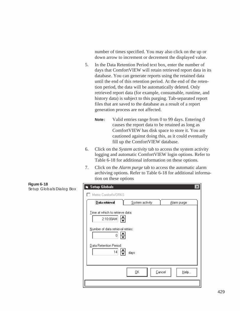
429
number of times specified. You may also click on the up ordown arrow to increment or decrement the displayed value.
5. In the Data Retention Period text box, enter the number ofdays that ComfortVIEW will retain retrieved report data in itsdatabase. You can generate reports using the retained datauntil the end of this retention period. At the end of the reten-tion period, the data will be automatically deleted. Onlyretrieved report data (for example, consumable, runtime, andhistory data) is subject to this purging. Tab-separated reportfiles that are saved to the database as a result of a reportgeneration process are not affected.
Note: Valid entries range from 0 to 99 days. Entering 0causes the report data to be retained as long asComfortVIEW has disk space to store it. You arecautioned against doing this, as it could eventuallyfill up the ComfortVIEW database.
6. Click on the System activity tab to access the system activitylogging and automatic ComfortVIEW login options. Refer toTable 6-18 for additional information on these options.
7. Click on the Alarm purge tab to access the automatic alarmarchiving options. Refer to Table 6-18 for additional informa-tion on these options
Figure 6-18Setup Globals Dialog Box
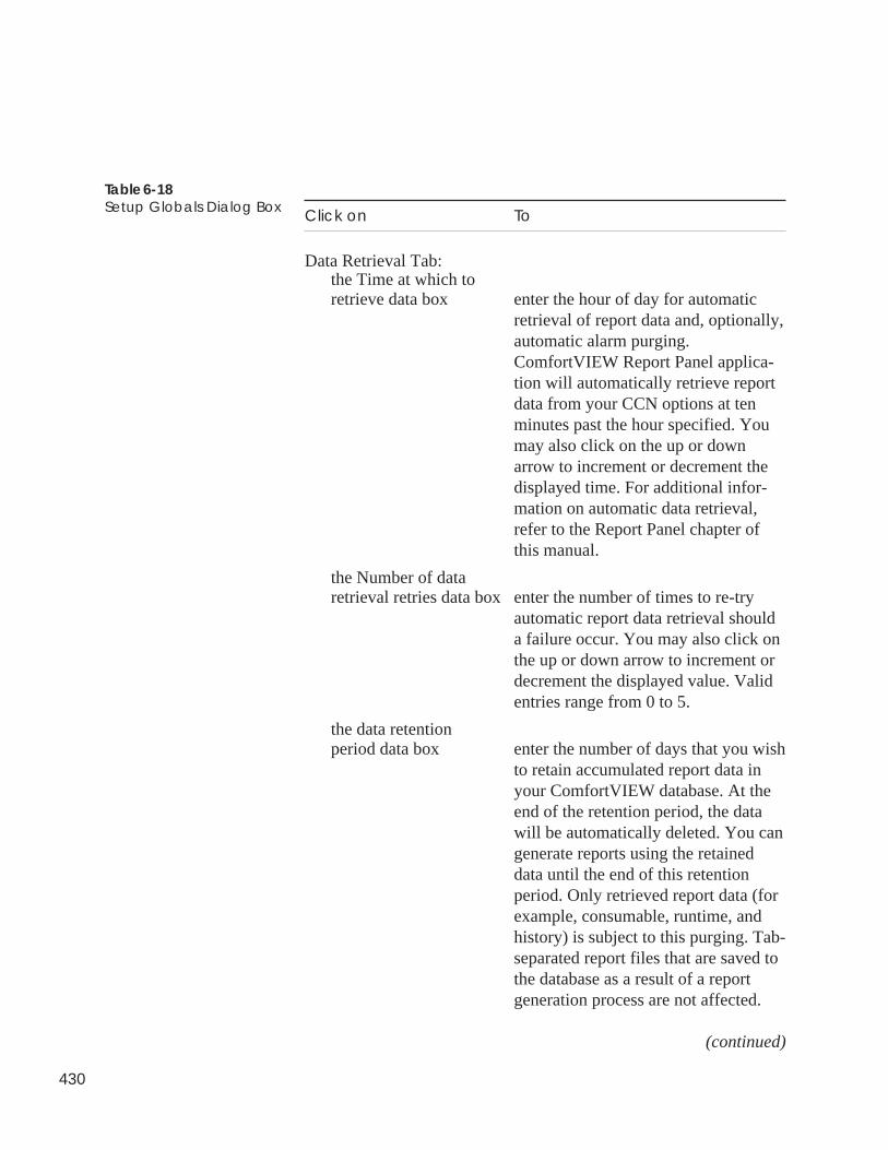
430
Click on To
Data Retrieval Tab:the Time at which toretrieve data box enter the hour of day for automatic
retrieval of report data and, optionally,automatic alarm purging.ComfortVIEW Report Panel applica-tion will automatically retrieve reportdata from your CCN options at tenminutes past the hour specified. Youmay also click on the up or downarrow to increment or decrement thedisplayed time. For additional infor-mation on automatic data retrieval,refer to the Report Panel chapter ofthis manual.
the Number of dataretrieval retries data box enter the number of times to re-try
automatic report data retrieval shoulda failure occur. You may also click onthe up or down arrow to increment ordecrement the displayed value. Validentries range from 0 to 5.
the data retentionperiod data box enter the number of days that you wish
to retain accumulated report data inyour ComfortVIEW database. At theend of the retention period, the datawill be automatically deleted. You cangenerate reports using the retaineddata until the end of this retentionperiod. Only retrieved report data (forexample, consumable, runtime, andhistory) is subject to this purging. Tab-separated report files that are saved tothe database as a result of a reportgeneration process are not affected.
(continued)
Table 6-18Setup Globals Dialog Box
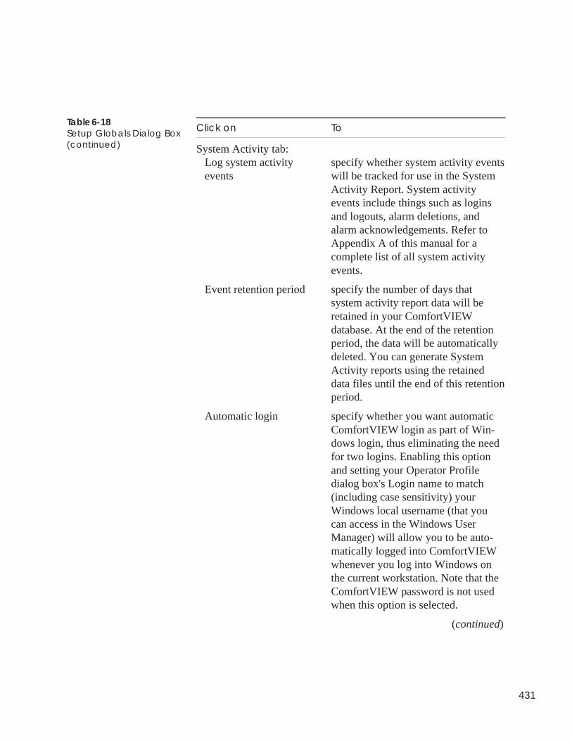
431
Table 6-18Setup Globals Dialog Box(continued)
Click on To
System Activity tab:Log system activity specify whether system activity eventsevents will be tracked for use in the System
Activity Report. System activityevents include things such as loginsand logouts, alarm deletions, andalarm acknowledgements. Refer toAppendix A of this manual for acomplete list of all system activityevents.
Event retention period specify the number of days thatsystem activity report data will beretained in your ComfortVIEWdatabase. At the end of the retentionperiod, the data will be automaticallydeleted. You can generate SystemActivity reports using the retaineddata files until the end of this retentionperiod.
Automatic login specify whether you want automaticComfortVIEW login as part of Win-dows login, thus eliminating the needfor two logins. Enabling this optionand setting your Operator Profiledialog box's Login name to match(including case sensitivity) yourWindows local username (that youcan access in the Windows UserManager) will allow you to be auto-matically logged into ComfortVIEWwhenever you log into Windows onthe current workstation. Note that theComfortVIEW password is not usedwhen this option is selected.
(continued)
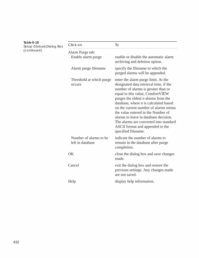
432
Click on To
Alarm Purge tab:Enable alarm purge enable or disable the automatic alarm
archiving and deletion option.
Alarm purge filename specify the filename to which thepurged alarms will be appended.
Threshold at which purge enter the alarm purge limit. At theoccurs designated data retrieval time, if the
number of alarms is greater than orequal to this value, ComfortVIEWpurges the oldest n alarms from thedatabase, where n is calculated basedon the current number of alarms minusthe value entered in the Number ofalarms to leave in database decision.The alarms are converted into standardASCII format and appended to thespecified filename.
Number of alarms to be indicate the number of alarms toleft in database remain in the database after purge
completion.
OK close the dialog box and save changesmade.
Cancel exit the dialog box and restore theprevious settings. Any changes madeare not saved.
Help display help information.
Table 6-18Setup Globals Dialog Box(continued)
433
ComfortVIEW gives you the capability to back up an entire CCN'sdatabase to another directory, sub-directory, or drive. You shouldmake it a practice to periodically back up your CCN database in theevent that a malfunction should occur with your hard disk. Becauseit allows you to copy a CCN database from one PC to another, thisfunction could also be helpful to Carrier service personnel for in-office preparation of a ComfortVIEW field database.
CCN export copies the selected CCN's entire database to the speci-fied drive. This drive can be the ComfortVIEW floppy diskettedrive, another ComfortVIEW hard drive partition, or another com-puter on the local area network. The information that will be copiedincludes:
• the CCN name and number
• the area name(s)
• all controllers and all associated configuration
• WorkSPACEs that contain points from the specified CCN (andthe associated ViewSPACEs and trends — including graphicbackgrounds and databoxes from the specified CCN)
Note: WorkSPACEs that contain links to these WorkSPACEs,as well as WorkSPACEs that are linked to by theseWorkSPACEs, will also be included.
• Report definitions that contain points from the specified CCN
• All System Activity report definitions.
This CCN database information can be copied back, or imported toComfortVIEW at any time, using the File menu's Import command.For additional information, refer to Importing CCNs, which appearslater in this Setup chapter.
Follow the instructions below to export a CCN from theComfortVIEW hard disk:
1. Display the Setup window. If necessary, refer to Launchingthe Setup Application.
2. Click on the File menu item and then click on Export CCN.
The Export CCN Selection dialog box will be displayed.Refer to Figure 6-19.
Note: You may also perform this command by clicking onthe Export CCN icon in the toolbar.
Exporting CCNs
434
3. Click on the CCN that you wish to export, and then click onOK.
The Export Target Selection dialog box will be displayed.
4. In the Export Target Selection dialog box, select the directoryand drive where you want the file saved. Refer to Table 6-20for more information on using the Export Target Selectiondialog box.
5. Click on OK to export the CCN to the specified file name andlocation.
ComfortVIEW displays a dialog box asking for confirmationbefore copying the selected CCN. Click on Yes to completethe export, or click on No to prevent the export from takingplace.
ComfortVIEW will save the exported files to the specifieddirectory using the following file naming convention:00000xxx, where xxx is the CCN number.
A function status box is displayed during the copy process. Ifyou are exporting to diskette, ComfortVIEW will prompt youto insert another diskette, if necessary. The message Functioncompleted successfully displays on completion.
Note: The ComfortVIEW export procedure will terminateif any single file to be exported is larger in size thanthe diskette to which you are exporting. For ex-ample, if you are exporting to a 720 kb diskette, anda graphic file is 1 Mb in size, the export procedurewill terminate.
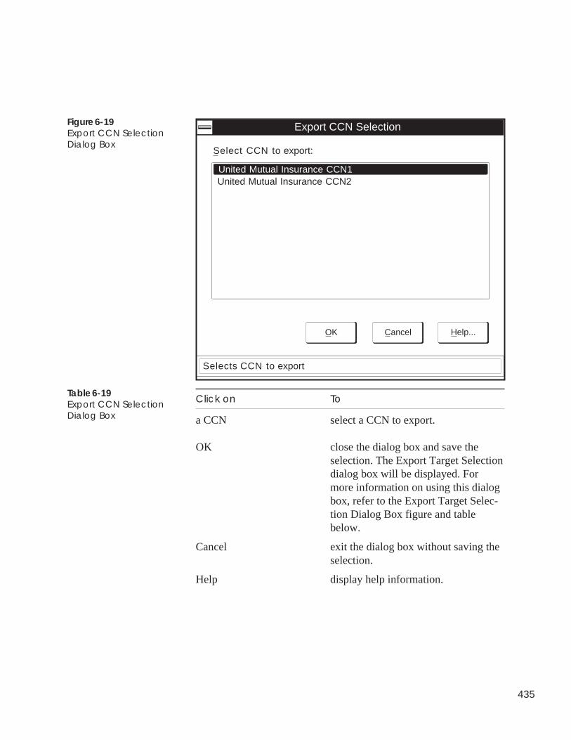
435
Export CCN Selection
Select CCN to export:
United Mutual Insurance CCN1United Mutual Insurance CCN2
Selects CCN to export
Help...CancelOK
Figure 6-19Export CCN SelectionDialog Box
Click on To
a CCN select a CCN to export.
OK close the dialog box and save theselection. The Export Target Selectiondialog box will be displayed. Formore information on using this dialogbox, refer to the Export Target Selec-tion Dialog Box figure and tablebelow.
Cancel exit the dialog box without saving theselection.
Help display help information.
Table 6-19Export CCN SelectionDialog Box
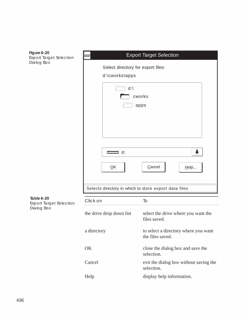
436
d:\cworks\apps
Export Target Selection
Select directory for export files:
Help...CancelOK
Selects directory in which to store export data files
d:\
cworks
apps
d:
Figure 6-20Export Target SelectionDialog Box
Click on To
the drive drop down list select the drive where you want thefiles saved.
a directory to select a directory where you wantthe files saved.
OK close the dialog box and save theselection.
Cancel exit the dialog box without saving theselection.
Help display help information.
Table 6-20Export Target SelectionDialog Box
437
You can use the File menu's Import CCN command to copy previ-ously-exported CCN database files to ComfortVIEW. This functionwould typically be used by a Carrier representative during off-linepreparation of a ComfortVIEW database.
CCN database files that were previously exported using the Filemenu's Export CCN command, will be copied to the ComfortVIEWdatabase.
Follow the instructions below to import previously exported CCNdatabase files to a ComfortVIEW hard disk:
1. Display the Setup window. If necessary, refer to Launchingthe Setup Application.
2. Click on the File menu item and then click on Import CCN.
Note: You may also perform this command by clicking onthe Import CCN icon in the toolbar.
The Import Source Selection dialog box will be displayed.Refer to Figure 6-21.
3. In the Import Source Selection dialog box, select the driveand directory that contains the CCN that you wish to import,and then click on OK.
ComfortVIEW displays the Imported CCN Definition dialogbox. This dialog box functions the same as the New CCNDefinition dialog box that displays when you are adding anew CCN.
4. Enter the name and number of the CCN being imported. CCNnames may consist of up to 48 characters. If necessary, referto Figure 6-22 and Table 6-22 for instructions on using theCCN Definition dialog box.
Note: You must enter a unique CCN name and number. Ifthe new CCN name or number is already used in thetarget ComfortVIEW database, a notification mes-sage will be displayed and the CCN Definitiondialog box will be re-displayed.
5. Make any other modifications, and then click on OK to closethe Imported CCN Definition dialog box and start the import.
A confirmation dialog box will be displayed asking if youwish to import the specified CCN.
Importing CCNs

438
6. Click on Yes to start the import or on No to close the dialogbox without importing.
A function status box will display during the import process.ComfortVIEW will copy all previously-exported CCN data-base files from the specified drive and directory to the newCCN name and number. In the new CCN, ComfortVIEW willprecede the imported area names with the new CCN name.
Note: If, during the import, ComfortVIEW finds that thename of a database item being imported alreadyexists in the target ComfortVIEW database, the NewName dialog box will be displayed. You can eitherenter a new name for the imported item, overwritethe original item with the one being imported, orskip the importing of this item. If necessary, refer toFigure 6-23 and Table 6-23 for instructions on usingthe New Name dialog box.
The message Function completed successfully displays oncompletion.
7. You should now launch the Carrier Network Manager appli-cation and set up the access parameters for the new CCN. SeeModifying CCNs in the Adding/Modifying CCNs section ofthis manual's Carrier Network Manager chapter. The im-ported CCN and address will default to Database Only andSystem Element 239. You can modify these values as re-quired.
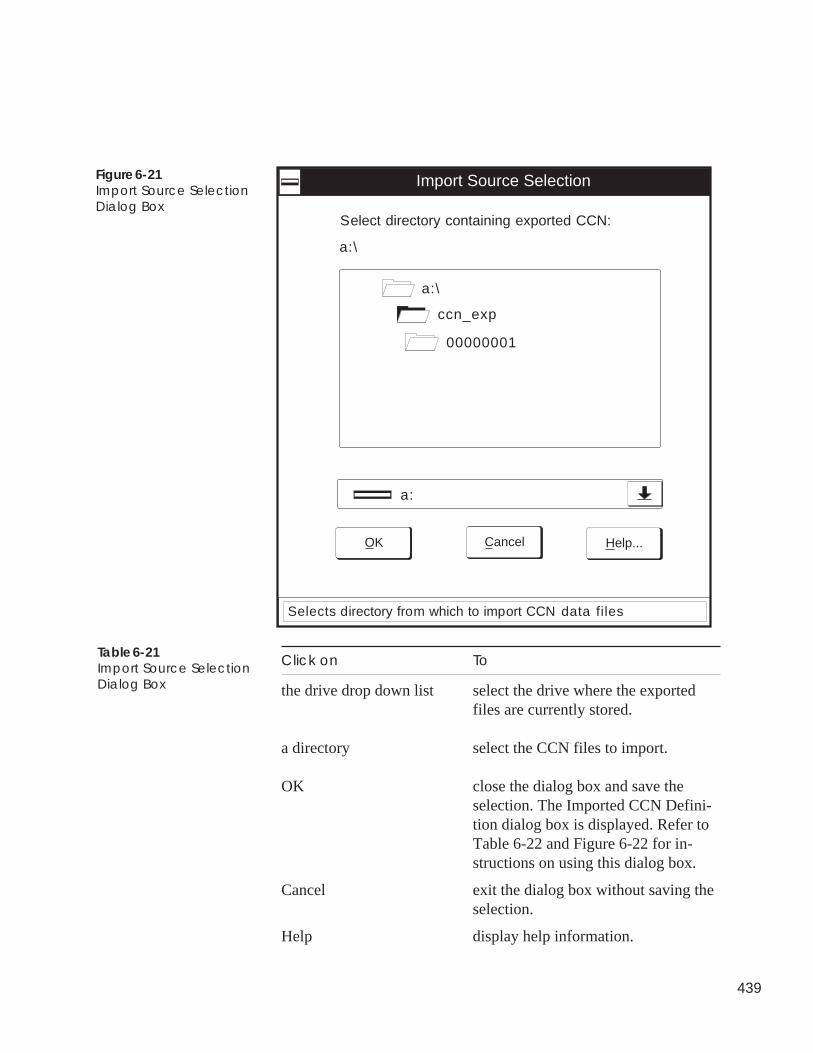
439
Figure 6-21Import Source SelectionDialog Box
Click on To
the drive drop down list select the drive where the exportedfiles are currently stored.
a directory select the CCN files to import.
OK close the dialog box and save theselection. The Imported CCN Defini-tion dialog box is displayed. Refer toTable 6-22 and Figure 6-22 for in-structions on using this dialog box.
Cancel exit the dialog box without saving theselection.
Help display help information.
a:\
Import Source Selection
Select directory containing exported CCN:
Help...CancelOK
Selects directory from which to import CCN data files
a:\
ccn_exp
00000001
a:
Table 6-21Import Source SelectionDialog Box
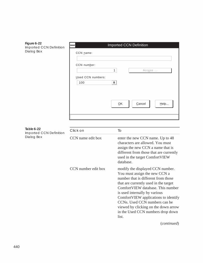
440
Used CCN numbers:
Imported CCN Definition
CCN name:
OK Cancel Help...
100
CCN number:
1 Access ...
Table 6-22Imported CCN DefinitionDialog Box
Figure 6-22Imported CCN DefinitionDialog Box
Click on To
CCN name edit box enter the new CCN name. Up to 48characters are allowed. You mustassign the new CCN a name that isdifferent from those that are currentlyused in the target ComfortVIEWdatabase.
CCN number edit box modify the displayed CCN number.You must assign the new CCN anumber that is different from thosethat are currently used in the targetComfortVIEW database. This numberis used internally by variousComfortVIEW applications to identifyCCNs. Used CCN numbers can beviewed by clicking on the down arrowin the Used CCN numbers drop downlist.
(continued)
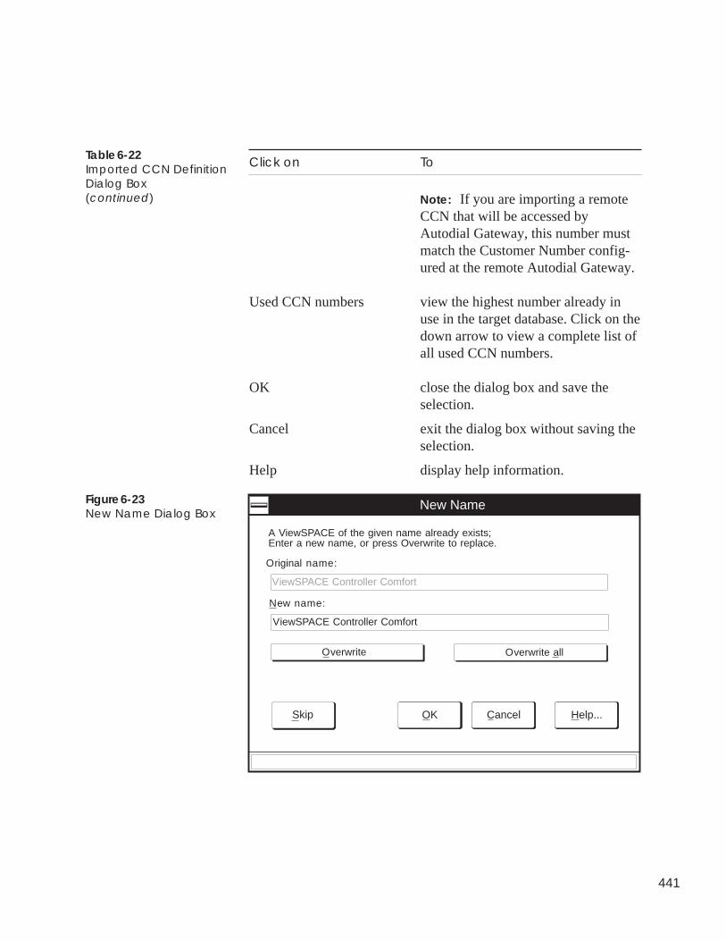
441
Click on To
Note: If you are importing a remoteCCN that will be accessed byAutodial Gateway, this number mustmatch the Customer Number config-ured at the remote Autodial Gateway.
Used CCN numbers view the highest number already inuse in the target database. Click on thedown arrow to view a complete list ofall used CCN numbers.
OK close the dialog box and save theselection.
Cancel exit the dialog box without saving theselection.
Help display help information.
Table 6-22Imported CCN DefinitionDialog Box(continued)
Figure 6-23New Name Dialog Box
New Name
Cancel Help...
A ViewSPACE of the given name already exists;Enter a new name, or press Overwrite to replace.
Original name:
ViewSPACE Controller Comfort
New name:
ViewSPACE Controller Comfort
Overwrite Overwrite all
OKSkip
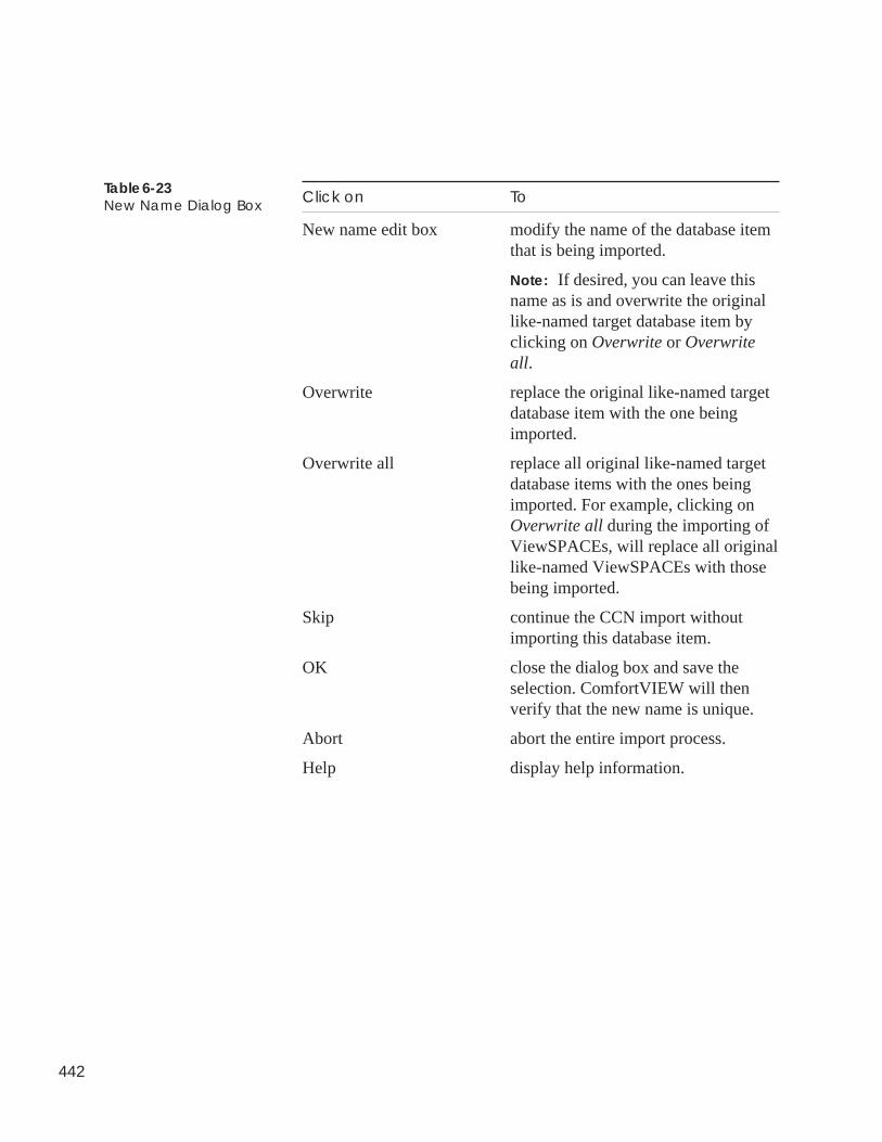
442
Click on To
New name edit box modify the name of the database itemthat is being imported.
Note: If desired, you can leave thisname as is and overwrite the originallike-named target database item byclicking on Overwrite or Overwriteall.
Overwrite replace the original like-named targetdatabase item with the one beingimported.
Overwrite all replace all original like-named targetdatabase items with the ones beingimported. For example, clicking onOverwrite all during the importing ofViewSPACEs, will replace all originallike-named ViewSPACEs with thosebeing imported.
Skip continue the CCN import withoutimporting this database item.
OK close the dialog box and save theselection. ComfortVIEW will thenverify that the new name is unique.
Abort abort the entire import process.
Help display help information.
Table 6-23New Name Dialog Box
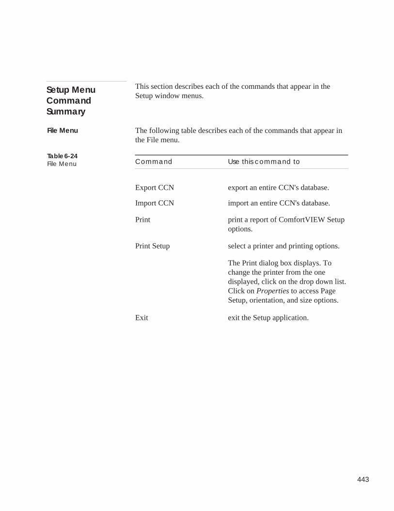
443
This section describes each of the commands that appear in theSetup window menus.
The following table describes each of the commands that appear inthe File menu.
Command Use this command to
Export CCN export an entire CCN's database.
Import CCN import an entire CCN's database.
Print print a report of ComfortVIEW Setupoptions.
Print Setup select a printer and printing options.
The Print dialog box displays. Tochange the printer from the onedisplayed, click on the drop down list.Click on Properties to access PageSetup, orientation, and size options.
Exit exit the Setup application.
Setup MenuCommandSummary
File Menu
Table 6-24File Menu
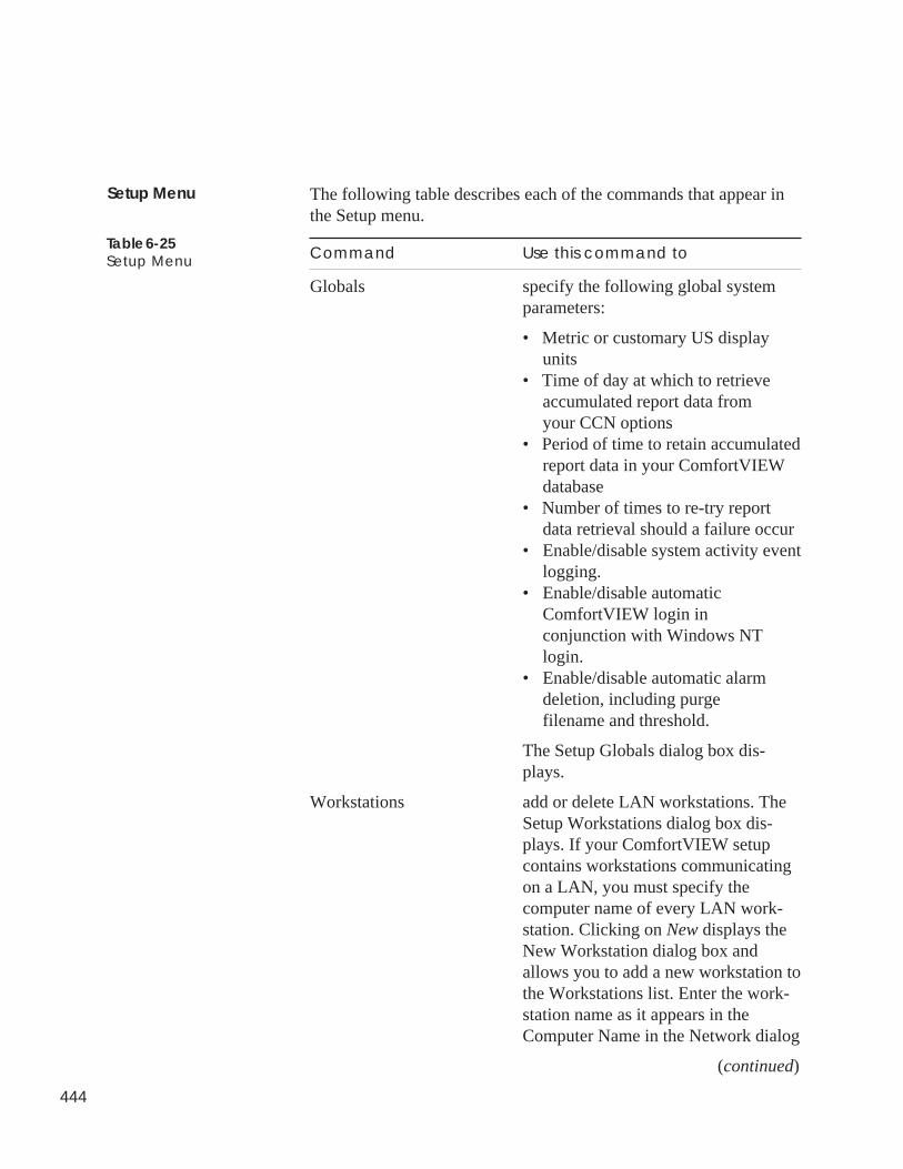
444
The following table describes each of the commands that appear inthe Setup menu.
Command Use this command to
Globals specify the following global systemparameters:
• Metric or customary US displayunits
• Time of day at which to retrieveaccumulated report data fromyour CCN options
• Period of time to retain accumulatedreport data in your ComfortVIEWdatabase
• Number of times to re-try reportdata retrieval should a failure occur
• Enable/disable system activity eventlogging.
• Enable/disable automaticComfortVIEW login inconjunction with Windows NTlogin.
• Enable/disable automatic alarmdeletion, including purgefilename and threshold.
The Setup Globals dialog box dis-plays.
Workstations add or delete LAN workstations. TheSetup Workstations dialog box dis-plays. If your ComfortVIEW setupcontains workstations communicatingon a LAN, you must specify thecomputer name of every LAN work-station. Clicking on New displays theNew Workstation dialog box andallows you to add a new workstation tothe Workstations list. Enter the work-station name as it appears in theComputer Name in the Network dialog
(continued)
Setup Menu
Table 6-25Setup Menu
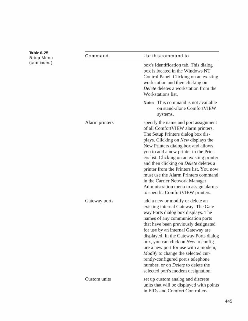
445
Command Use this command to
box's Identification tab. This dialogbox is located in the Windows NTControl Panel. Clicking on an existingworkstation and then clicking onDelete deletes a workstation from theWorkstations list.
Note: This command is not availableon stand-alone ComfortVIEWsystems.
Alarm printers specify the name and port assignmentof all ComfortVIEW alarm printers.The Setup Printers dialog box dis-plays. Clicking on New displays theNew Printers dialog box and allowsyou to add a new printer to the Print-ers list. Clicking on an existing printerand then clicking on Delete deletes aprinter from the Printers list. You nowmust use the Alarm Printers commandin the Carrier Network ManagerAdministration menu to assign alarmsto specific ComfortVIEW printers.
Gateway ports add a new or modify or delete anexisting internal Gateway. The Gate-way Ports dialog box displays. Thenames of any communication portsthat have been previously designatedfor use by an internal Gateway aredisplayed. In the Gateway Ports dialogbox, you can click on New to config-ure a new port for use with a modem,Modify to change the selected cur-rently-configured port's telephonenumber, or on Delete to delete theselected port's modem designation.
Custom units set up custom analog and discreteunits that will be displayed with pointsin FIDs and Comfort Controllers.
Table 6-25Setup Menu(continued)
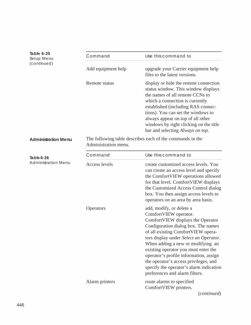
446
Command Use this command to
Add equipment help upgrade your Carrier equipment helpfiles to the latest versions.
Remote status display or hide the remote connectionstatus window. This window displaysthe names of all remote CCNs towhich a connection is currentlyestablished (including RAS connec-tions). You can set the windows toalways appear on top of all otherwindows by right clicking on the titlebar and selecting Always on top.
The following table describes each of the commands in theAdministration menu.
Command Use this command to
Access levels create customized access levels. Youcan create an access level and specifythe ComfortVIEW operations allowedfor that level. ComfortVIEW displaysthe Customized Access Control dialogbox. You then assign access levels tooperators on an area by area basis.
Operators add, modify, or delete aComfortVIEW operator.ComfortVIEW displays the OperatorConfiguration dialog box. The namesof all existing ComfortVIEW opera-tors display under Select an Operator.When adding a new or modifying anexisting operator you must enter theoperator’s profile information, assignthe operator’s access privileges, andspecify the operator’s alarm indicationpreferences and alarm filters.
Alarm printers route alarms to specifiedComfortVIEW printers. (continued)
Administration Menu
Table 6-26Administration Menu
Table 6-25Setup Menu(continued)
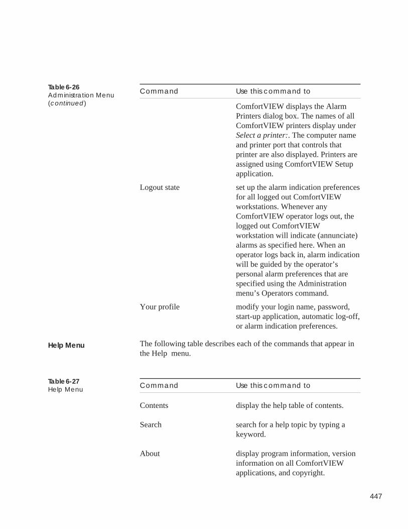
447
Table 6-26Administration Menu(continued)
Command Use this command to
ComfortVIEW displays the AlarmPrinters dialog box. The names of allComfortVIEW printers display underSelect a printer:. The computer nameand printer port that controls thatprinter are also displayed. Printers areassigned using ComfortVIEW Setupapplication.
Logout state set up the alarm indication preferencesfor all logged out ComfortVIEWworkstations. Whenever anyComfortVIEW operator logs out, thelogged out ComfortVIEWworkstation will indicate (annunciate)alarms as specified here. When anoperator logs back in, alarm indicationwill be guided by the operator’spersonal alarm preferences that arespecified using the Administrationmenu’s Operators command.
Your profile modify your login name, password,start-up application, automatic log-off,or alarm indication preferences.
The following table describes each of the commands that appear inthe Help menu.
Command Use this command to
Contents display the help table of contents.
Search search for a help topic by typing akeyword.
About display program information, versioninformation on all ComfortVIEWapplications, and copyright.
Help Menu
Table 6-27Help Menu

448

Report Panel

Alarm Manager
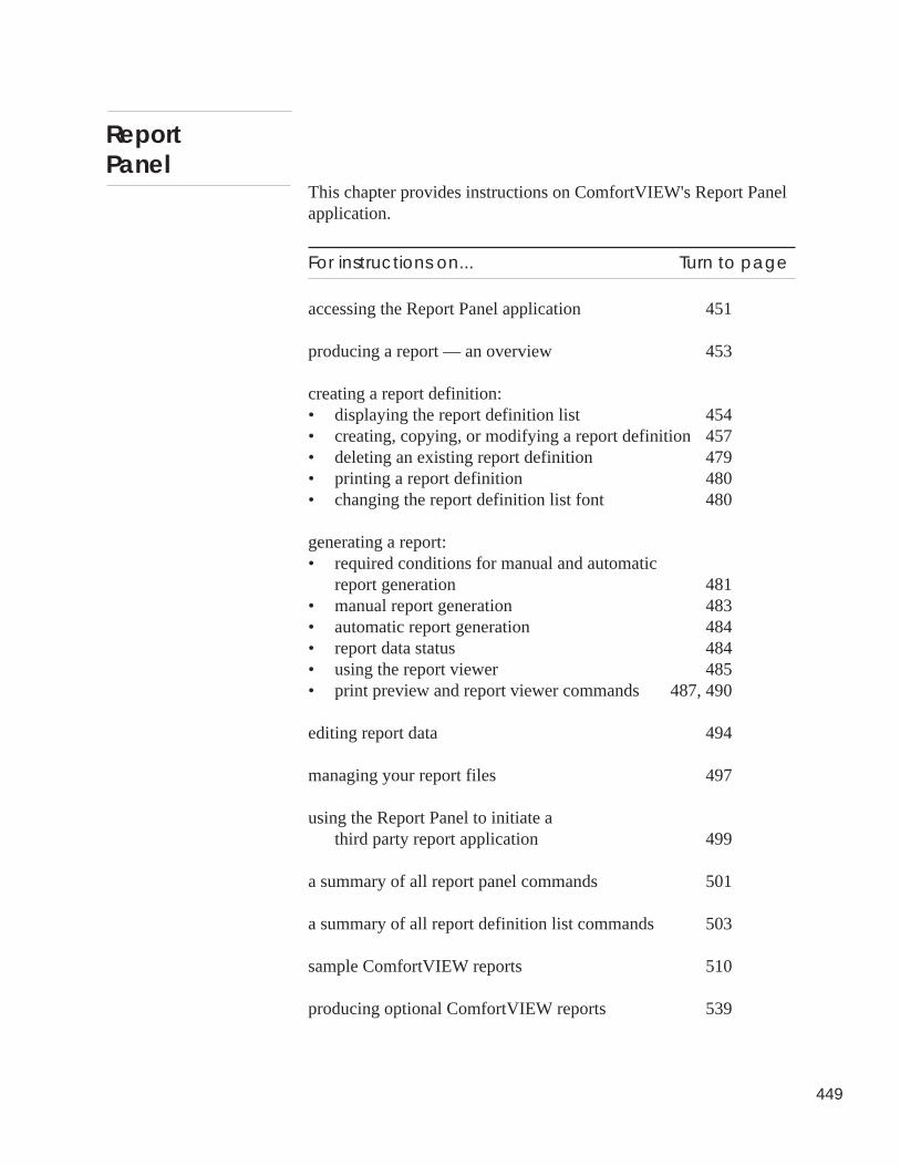
449
This chapter provides instructions on ComfortVIEW's Report Panelapplication.
For instructions on... Turn to page
accessing the Report Panel application 451
producing a report — an overview 453
creating a report definition:• displaying the report definition list 454• creating, copying, or modifying a report definition 457• deleting an existing report definition 479• printing a report definition 480• changing the report definition list font 480
generating a report:• required conditions for manual and automatic
report generation 481• manual report generation 483• automatic report generation 484• report data status 484• using the report viewer 485• print preview and report viewer commands 487, 490
editing report data 494
managing your report files 497
using the Report Panel to initiate athird party report application 499
a summary of all report panel commands 501
a summary of all report definition list commands 503
sample ComfortVIEW reports 510
producing optional ComfortVIEW reports 539
ReportPanel
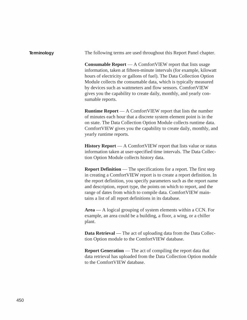
450
The following terms are used throughout this Report Panel chapter.
Consumable Report — A ComfortVIEW report that lists usageinformation, taken at fifteen-minute intervals (for example, kilowatthours of electricity or gallons of fuel). The Data Collection OptionModule collects the consumable data, which is typically measuredby devices such as wattmeters and flow sensors. ComfortVIEWgives you the capability to create daily, monthly, and yearly con-sumable reports.
Runtime Report — A ComfortVIEW report that lists the numberof minutes each hour that a discrete system element point is in theon state. The Data Collection Option Module collects runtime data.ComfortVIEW gives you the capability to create daily, monthly, andyearly runtime reports.
History Report — A ComfortVIEW report that lists value or statusinformation taken at user-specified time intervals. The Data Collec-tion Option Module collects history data.
Report Definition — The specifications for a report. The first stepin creating a ComfortVIEW report is to create a report definition. Inthe report definition, you specify parameters such as the report nameand description, report type, the points on which to report, and therange of dates from which to compile data. ComfortVIEW main-tains a list of all report definitions in its database.
Area — A logical grouping of system elements within a CCN. Forexample, an area could be a building, a floor, a wing, or a chillerplant.
Data Retrieval — The act of uploading data from the Data Collec-tion Option module to the ComfortVIEW database.
Report Generation — The act of compiling the report data thatdata retrieval has uploaded from the Data Collection Option moduleto the ComfortVIEW database.
Terminology
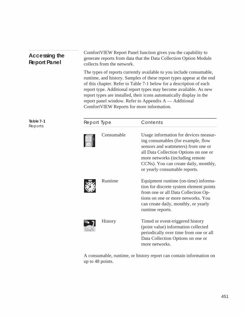
451
ComfortVIEW Report Panel function gives you the capability togenerate reports from data that the Data Collection Option Modulecollects from the network.
The types of reports currently available to you include consumable,runtime, and history. Samples of these report types appear at the endof this chapter. Refer to Table 7-1 below for a description of eachreport type. Additional report types may become available. As newreport types are installed, their icons automatically display in thereport panel window. Refer to Appendix A — AdditionalComfortVIEW Reports for more information.
Report Type Contents
Consumable Usage information for devices measur-ing consumables (for example, flowsensors and wattmeters) from one orall Data Collection Options on one ormore networks (including remoteCCNs). You can create daily, monthly,or yearly consumable reports.
Runtime Equipment runtime (on-time) informa-tion for discrete system element pointsfrom one or all Data Collection Op-tions on one or more networks. Youcan create daily, monthly, or yearlyruntime reports.
History Timed or event-triggered history(point value) information collectedperiodically over time from one or allData Collection Options on one ormore networks.
A consumable, runtime, or history report can contain information onup to 48 points.
Accessing theReport Panel
Table 7-1Reports
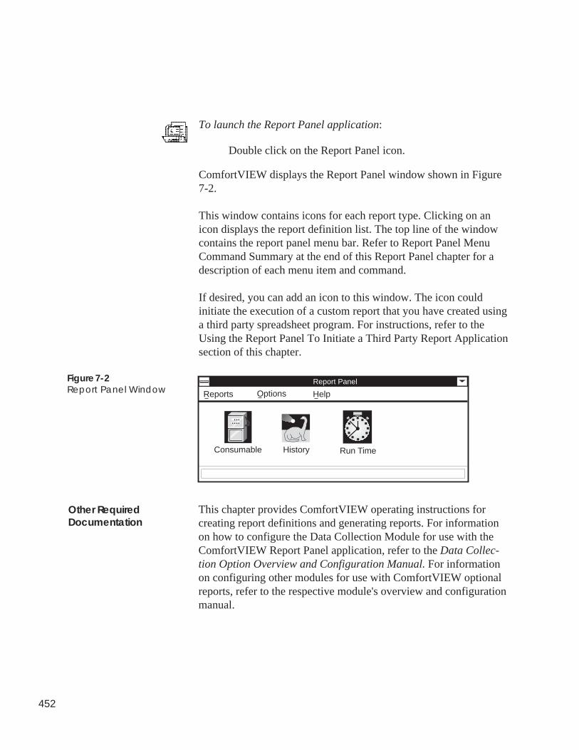
452
To launch the Report Panel application:
Double click on the Report Panel icon.
ComfortVIEW displays the Report Panel window shown in Figure7-2.
This window contains icons for each report type. Clicking on anicon displays the report definition list. The top line of the windowcontains the report panel menu bar. Refer to Report Panel MenuCommand Summary at the end of this Report Panel chapter for adescription of each menu item and command.
If desired, you can add an icon to this window. The icon couldinitiate the execution of a custom report that you have created usinga third party spreadsheet program. For instructions, refer to theUsing the Report Panel To Initiate a Third Party Report Applicationsection of this chapter.
Figure 7-2Report Panel Window
Report Panel
Reports Options Help
Consumable History Run Time
This chapter provides ComfortVIEW operating instructions forcreating report definitions and generating reports. For informationon how to configure the Data Collection Module for use with theComfortVIEW Report Panel application, refer to the Data Collec-tion Option Overview and Configuration Manual. For informationon configuring other modules for use with ComfortVIEW optionalreports, refer to the respective module's overview and configurationmanual.
Other RequiredDocumentation
453
The report creation process is summarized below. For more detailedreport creation instructions, refer to the Creating, Copying, or Modi-fying a Report Definition and Generating a Report sections of thischapter.
To produce a ComfortVIEW report you must perform the followingtasks:
1. Define the specifications for the report. You do this by creat-ing a report definition where you enter specifications such asthe report name and description, report type (daily, monthly,yearly), automatic data retrieval and report generation prefer-ences, and the points on which to report.
ComfortVIEW maintains a list of all report definitions in itsdatabase. You can view, modify, or delete a report definition,or re-generate a report from an existing definition at any time.You can also copy a report definition for use as a startingpoint in creating another report definition.
2. Manually generate the report, or, if you select automatic reportgeneration, the report automatically generates at a time that youspecify using the ComfortVIEW Setup application. WhenComfortVIEW generates a report, it retrieves data from thenetwork (or uses data that was already retrieved) and creates atemporary tab-separated report file. If desired, you can save thetab-delineated report file permanently on disk for use with thirdparty spreadsheet applications. You can also opt to print thereport file.
Report definitions define the specifications for your reports. Reportspecifications include information such as the report name anddescription, report type (daily, monthly, yearly), automatic dataretrieval and report generation preferences, and the points on whichto report.
Producing aReport — AnOverview
454
Follow the steps below to display a list of all existing report defini-tions.
1. Display the report panel. If necessary, refer to the instructionslisted under Accessing the Report Panel.
2. Click on the Reports menu item and then click on the reporttype (Consumable, History, Runtime, or System Activity).
Note: You may also perform this command by doubleclicking on the Report Panel’s Consumable, History,Runtime, or System Activity icon.
ComfortVIEW displays a Report Definition List window similar tothe one displayed in Figure 7-3. This window lists the up to 8character report name and up to 48 character description of allexisting report definitions for the type of report selected (consum-able, runtime, history, and system activity). Some of the reportdefinitions may be preceded by a red icon. These are reports thathave been specified to be automatically generated. Refer to theexplanation of the Report Definition Dialog Box that appears laterin this chapter for additional information on this option.
The top line of the window contains the menu bar. Refer to ReportDefinition List Menu Command Summary at the end of this chapterfor a description of each menu item and command.
The second line of the window contains the toolbar. Refer to ReportPanel Definition List Window Toolbar below for information onusing each toolbar button.
The third line of the window contains the status bar. This linedisplays the name and description of the currently highlighted reportdefinition.
Note: If desired, you can remove the status bar from the ReportDefinition List window by clicking on the Options menuitem followed by clicking on Status bar. To return thestatus bar to the window, perform these two commandsagain.
You may also change the window’s font and point size byclicking on the Options menu item followed by clickingon Font. For further instructions, refer to the Changing theFont section of this chapter.
Displaying theReport DefinitionList
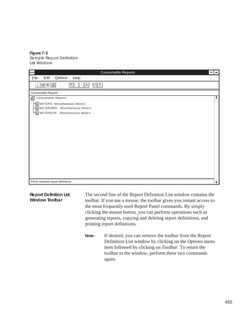
455
The second line of the Report Definition List window contains thetoolbar. If you use a mouse, the toolbar gives you instant access tothe most frequently used Report Panel commands. By simplyclicking the mouse button, you can perform operations such asgenerating reports, copying and deleting report definitions, andprinting report definitions.
Note: If desired, you can remove the toolbar from the ReportDefinition List window by clicking on the Options menuitem followed by clicking on Toolbar. To return thetoolbar to the window, perform these two commandsagain.
Figure 7-3Sample Report DefinitionList Window
Report Definition ListWindow Toolbar
Consumable Reports
Consumable Reports
Consumable Reports
File Options HelpEdit
METERS: Miscellaneous Meters
METERSMO: Miscellaneous Meters
METERSYR: Miscellaneous Meters
Prints selected report definitions
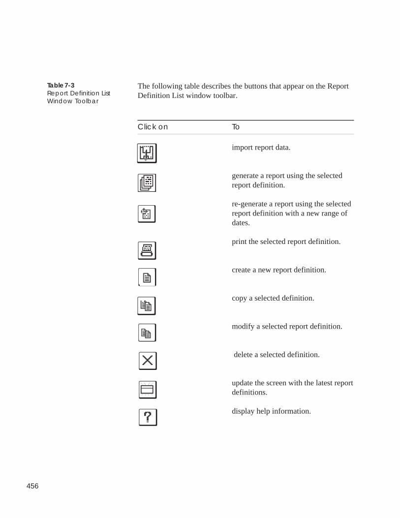
456
The following table describes the buttons that appear on the ReportDefinition List window toolbar.
Click on To
import report data.
generate a report using the selectedreport definition.
re-generate a report using the selectedreport definition with a new range ofdates.
print the selected report definition.
create a new report definition.
copy a selected definition.
modify a selected report definition.
delete a selected definition.
update the screen with the latest reportdefinitions.
display help information.
Table 7-3Report Definition ListWindow Toolbar
457
Creating,Copying, orModifying aReport Definition
To Create a NewReport Definition
1. Display the report definition list. If necessary, refer to Displayingthe Report Definition List.
2. Click on the File menu item and then click on New.
ComfortVIEW displays a Report Definition dialog box similar tothe ones shown in Figure 7-4 and Appendix A. You use thisdialog box to enter the specifications for a report.
Note: You may also perform this command by clicking on theAdd New report icon in the tool bar.
3. To produce a consumable, runtime, or history report, you mustenter the specifications shown below. For a list of specificationsfor other optional ComfortVIEW reports, refer to Appendix A.
• Report Name and Description• Report Type (None, Daily, Monthly, Yearly)• Manual Generation or Automatic Retrieval Options• Report Dates• Data Points on Which To Report• Format
Refer to Figure 7-4 and Table 7-4 and to Appendix A for instruc-tions on using the Report Definition dialog box.
4. Click on OK to exit the dialog box and save changes, or
click on Cancel to exit the dialog box without saving changes.
ComfortVIEW re-displays the report definition list.
Figures 7-8 to 7-10 display different Report Definition dialog boxconfigurations with explanations of the reports that will be pro-duced by each.
458
To Copy an ExistingReport Definition
To Modify an ExistingReport Definition
Follow the instructions below to create a new report definition by copyinga selected definition.
1. Display the report definition list. If necessary, refer to Displayingthe Report Definition List.
2. Click on the report definition you wish to copy.
3. Click on the Edit menu item and then click on Copy.
ComfortVIEW copies the selected report definition and displays thecopied Report Definition dialog box.
4. Enter the new Report Name, and, if desired, make any other modifi-cations.
Refer to Table 7-4 and Appendix A for instructions on using theReport Definition dialog box. Figures 7-8 to 7-10 display differentReport Definition dialog box configurations with explanations ofthe reports that will be produced by each.
5. Click on OK to exit the dialog box and save changes, or
click on Cancel to exit the dialog box without saving changes.
ComfortVIEW re-displays the report definition list.
1. Display the report definition list. If necessary, refer to Displayingthe Report Definition List.
2. Double click on the report definition to modify.
Note: You may also perform this command by clicking on areport in the report definition list followed by clicking onthe Edit menu item and then clicking on Modify.
ComfortVIEW displays a Report Definition dialog box similar tothe one shown in Figure 7-4 and Appendix A.
3. Modify the specifications as desired.
4. Click on OK to exit the dialog box and save changes, or
click on Cancel to exit the dialog box without saving changes.
ComfortVIEW re-displays the report definition list.
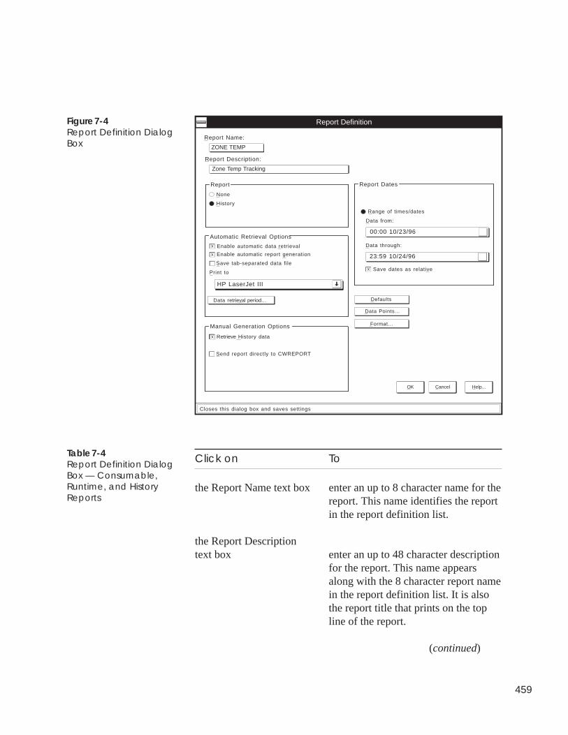
459
Figure 7-4Report Definition DialogBox
Click on To
the Report Name text box enter an up to 8 character name for thereport. This name identifies the reportin the report definition list.
the Report Descriptiontext box enter an up to 48 character description
for the report. This name appearsalong with the 8 character report namein the report definition list. It is alsothe report title that prints on the topline of the report.
(continued)
Table 7-4Report Definition DialogBox — Consumable,Runtime, and HistoryReports
Enable automatic data retrieval
History
Report Definition
Report Name:
OK Cancel Help...
X
None
Format...
Defaults
HP LaserJet III
ZONE TEMP
Report Description:
Zone Temp Tracking
Report
Save tab-separated data file
Print to
XEnable automatic report generation
Send report directly to CWREPORT
Retrieve History data
Manual Generation Options
00:00 10/23/96
Data from:
Range of times/dates
Report Dates
23:59 10/24/96
Data through:
Save dates as relative
X
X
Automatic Retrieval Options
Closes this dialog box and saves settings
Data Points...
Data retrieval period...
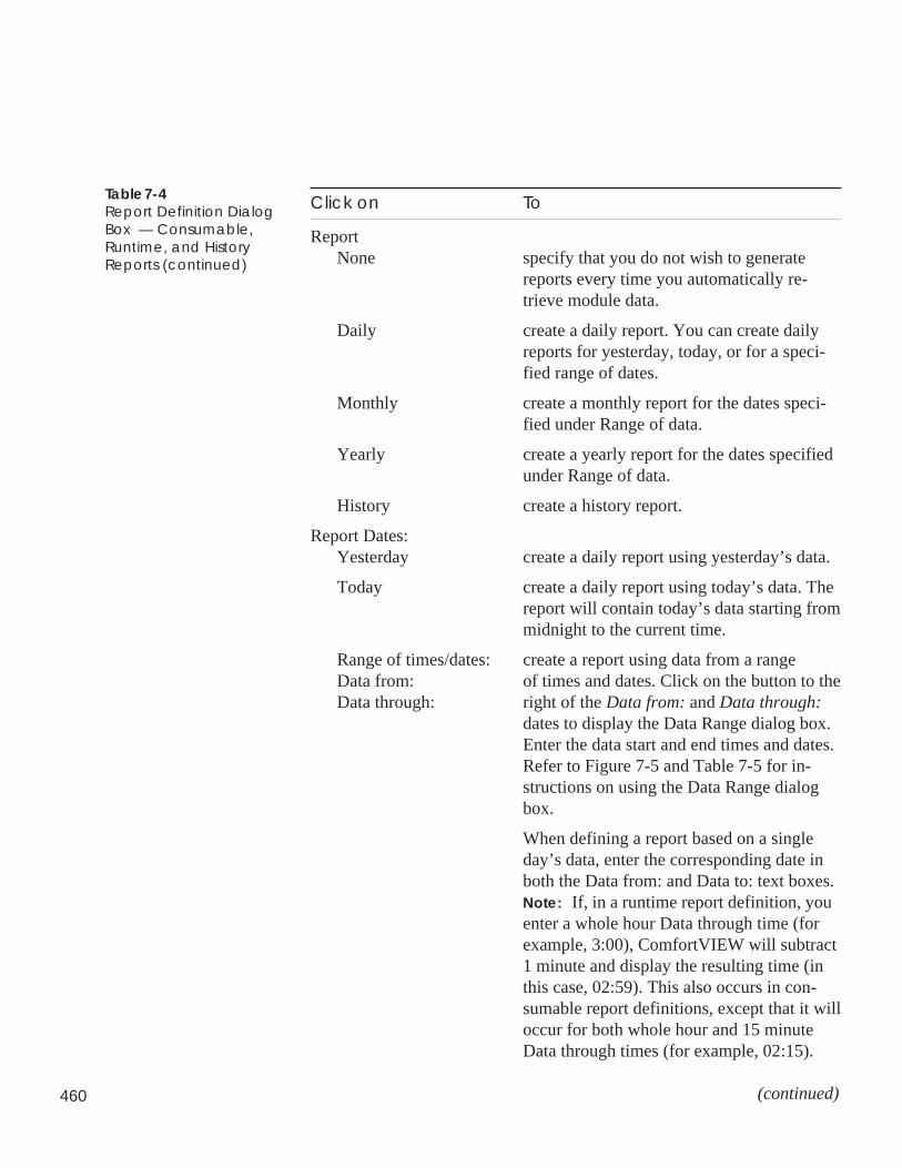
460
Click on To
ReportNone specify that you do not wish to generate
reports every time you automatically re-trieve module data.
Daily create a daily report. You can create dailyreports for yesterday, today, or for a speci-fied range of dates.
Monthly create a monthly report for the dates speci-fied under Range of data.
Yearly create a yearly report for the dates specifiedunder Range of data.
History create a history report.
Report Dates:Yesterday create a daily report using yesterday’s data.
Today create a daily report using today’s data. Thereport will contain today’s data starting frommidnight to the current time.
Range of times/dates: create a report using data from a rangeData from: of times and dates. Click on the button to theData through: right of the Data from: and Data through:
dates to display the Data Range dialog box.Enter the data start and end times and dates.Refer to Figure 7-5 and Table 7-5 for in-structions on using the Data Range dialogbox.
When defining a report based on a singleday’s data, enter the corresponding date inboth the Data from: and Data to: text boxes.Note: If, in a runtime report definition, youenter a whole hour Data through time (forexample, 3:00), ComfortVIEW will subtract1 minute and display the resulting time (inthis case, 02:59). This also occurs in con-sumable report definitions, except that it willoccur for both whole hour and 15 minuteData through times (for example, 02:15).
(continued)
Table 7-4Report Definition DialogBox — Consumable,Runtime, and HistoryReports (continued)
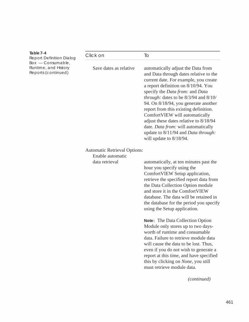
461
Click on To
Save dates as relative automatically adjust the Data fromand Data through dates relative to thecurrent date. For example, you createa report definition on 8/10/94. Youspecify the Data from: and Datathrough: dates to be 8/3/94 and 8/10/94. On 8/18/94, you generate anotherreport from this existing definition.ComfortVIEW will automaticallyadjust these dates relative to 8/18/94date. Data from: will automaticallyupdate to 8/11/94 and Data through:will update to 8/18/94.
Automatic Retrieval Options:Enable automaticdata retrieval automatically, at ten minutes past the
hour you specify using theComfortVIEW Setup application,retrieve the specified report data fromthe Data Collection Option moduleand store it in the ComfortVIEWdatabase. The data will be retained inthe database for the period you specifyusing the Setup application.
Note: The Data Collection OptionModule only stores up to two days-worth of runtime and consumabledata. Failure to retrieve module datawill cause the data to be lost. Thus,even if you do not wish to generate areport at this time, and have specifiedthis by clicking on None, you stillmust retrieve module data.
(continued)
Table 7-4Report Definition DialogBox — Consumable,Runtime, and HistoryReports (continued)
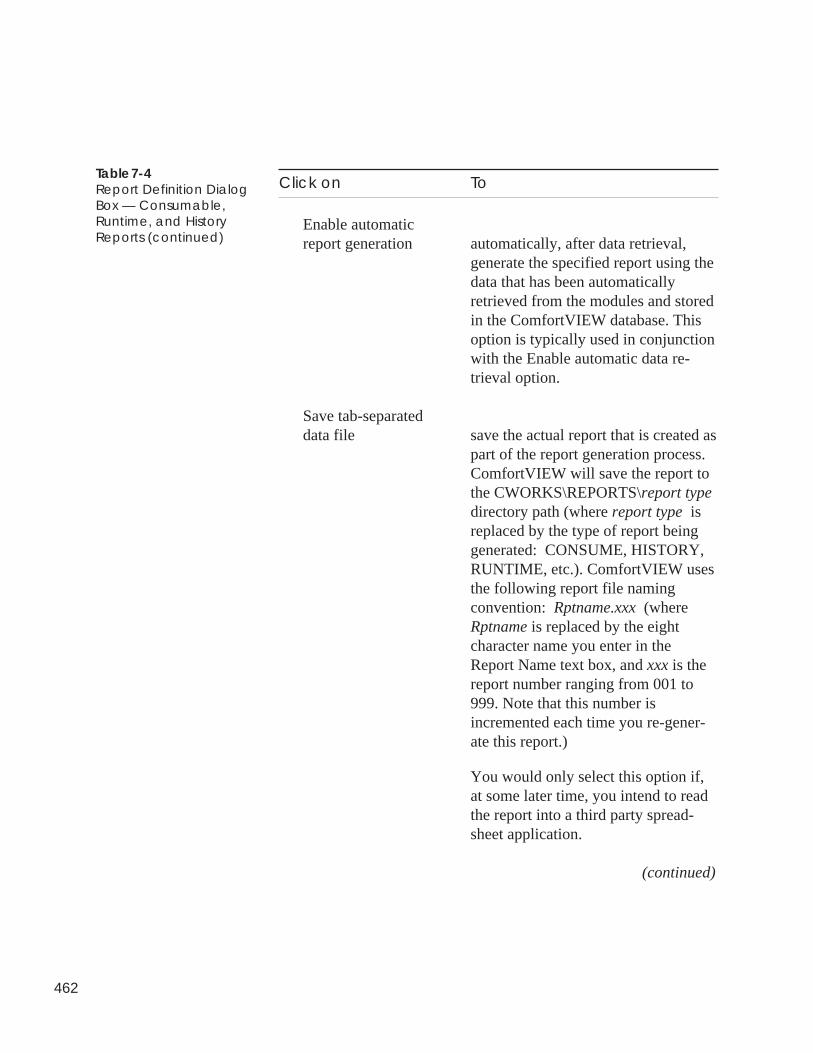
462
Click on To
Enable automaticreport generation automatically, after data retrieval,
generate the specified report using thedata that has been automaticallyretrieved from the modules and storedin the ComfortVIEW database. Thisoption is typically used in conjunctionwith the Enable automatic data re-trieval option.
Save tab-separateddata file save the actual report that is created as
part of the report generation process.ComfortVIEW will save the report tothe CWORKS\REPORTS\report typedirectory path (where report type isreplaced by the type of report beinggenerated: CONSUME, HISTORY,RUNTIME, etc.). ComfortVIEW usesthe following report file namingconvention: Rptname.xxx (whereRptname is replaced by the eightcharacter name you enter in theReport Name text box, and xxx is thereport number ranging from 001 to999. Note that this number isincremented each time you re-gener-ate this report.)
You would only select this option if,at some later time, you intend to readthe report into a third party spread-sheet application.
(continued)
Table 7-4Report Definition DialogBox — Consumable,Runtime, and HistoryReports (continued)
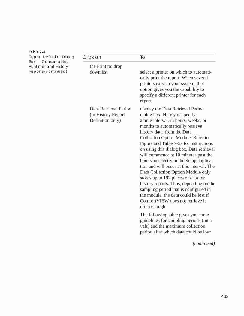
463
Click on To
the Print to: dropdown list select a printer on which to automati-
cally print the report. When severalprinters exist in your system, thisoption gives you the capability tospecify a different printer for eachreport.
Data Retrieval Period display the Data Retrieval Period(in History Report dialog box. Here you specifyDefinition only) a time interval, in hours, weeks, or
months to automatically retrievehistory data from the DataCollection Option Module. Refer toFigure and Table 7-5a for instructionson using this dialog box. Data retrievalwill commence at 10 minutes past thehour you specify in the Setup applica-tion and will occur at this interval. TheData Collection Option Module onlystores up to 192 pieces of data forhistory reports. Thus, depending on thesampling period that is configured inthe module, the data could be lost ifComfortVIEW does not retrieve itoften enough.
The following table gives you someguidelines for sampling periods (inter-vals) and the maximum collectionperiod after which data could be lost:
(continued)
Table 7-4Report Definition DialogBox — Consumable,Runtime, and HistoryReports (continued)
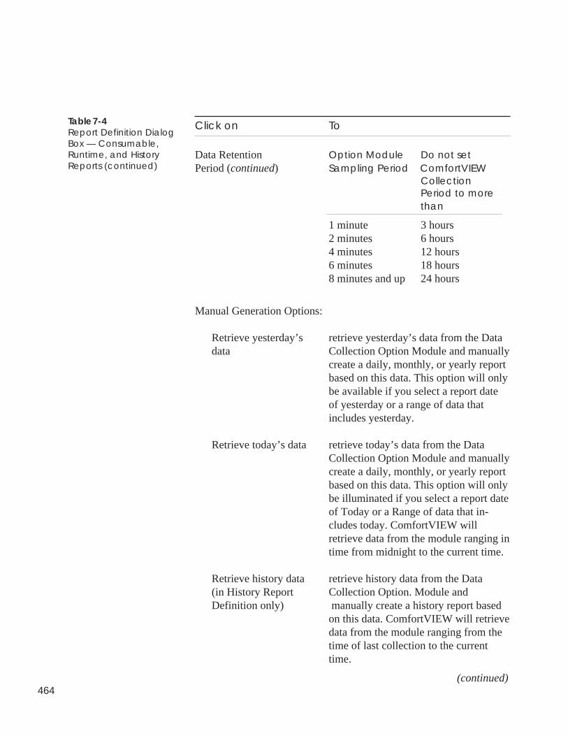
464
Click on To
Data Retention Option Module Do not setPeriod (continued) Sampling Period ComfortVIEW
CollectionPeriod to morethan
1 minute 3 hours2 minutes 6 hours4 minutes 12 hours6 minutes 18 hours8 minutes and up 24 hours
Manual Generation Options:
Retrieve yesterday’s retrieve yesterday’s data from the Datadata Collection Option Module and manually
create a daily, monthly, or yearly reportbased on this data. This option will onlybe available if you select a report dateof yesterday or a range of data thatincludes yesterday.
Retrieve today’s data retrieve today’s data from the DataCollection Option Module and manuallycreate a daily, monthly, or yearly reportbased on this data. This option will onlybe illuminated if you select a report dateof Today or a Range of data that in-cludes today. ComfortVIEW willretrieve data from the module ranging intime from midnight to the current time.
Retrieve history data retrieve history data from the Data(in History Report Collection Option. Module andDefinition only) manually create a history report based
on this data. ComfortVIEW will retrievedata from the module ranging from thetime of last collection to the currenttime.
(continued)
Table 7-4Report Definition DialogBox — Consumable,Runtime, and HistoryReports (continued)
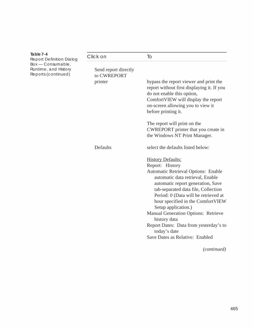
465
Click on To
Send report directlyto CWREPORTprinter bypass the report viewer and print the
report without first displaying it. If youdo not enable this option,ComfortVIEW will display the reporton-screen allowing you to view itbefore printing it.
The report will print on theCWREPORT printer that you create inthe Windows NT Print Manager.
Defaults select the defaults listed below:
History Defaults:Report: HistoryAutomatic Retrieval Options: Enable
automatic data retrieval, Enableautomatic report generation, Savetab-separated data file, CollectionPeriod: 0 (Data will be retrieved athour specified in the ComfortVIEWSetup application.)
Manual Generation Options: Retrievehistory data
Report Dates: Data from yesterday’s totoday’s date
Save Dates as Relative: Enabled
(continued)
Table 7-4Report Definition DialogBox — Consumable,Runtime, and HistoryReports (continued)
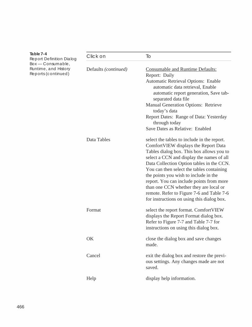
466
Click on To
Defaults (continued) Consumable and Runtime Defaults:Report: DailyAutomatic Retrieval Options: Enable
automatic data retrieval, Enableautomatic report generation, Save tab-separated data file
Manual Generation Options: Retrievetoday’s data
Report Dates: Range of Data: Yesterdaythrough today
Save Dates as Relative: Enabled
Data Tables select the tables to include in the report.ComfortVIEW displays the Report DataTables dialog box. This box allows you toselect a CCN and display the names of allData Collection Option tables in the CCN.You can then select the tables containingthe points you wish to include in thereport. You can include points from morethan one CCN whether they are local orremote. Refer to Figure 7-6 and Table 7-6for instructions on using this dialog box.
Format select the report format. ComfortVIEWdisplays the Report Format dialog box.Refer to Figure 7-7 and Table 7-7 forinstructions on using this dialog box.
OK close the dialog box and save changesmade.
Cancel exit the dialog box and restore the previ-ous settings. Any changes made are notsaved.
Help display help information.
Table 7-4Report Definition DialogBox — Consumable,Runtime, and HistoryReports (continued)
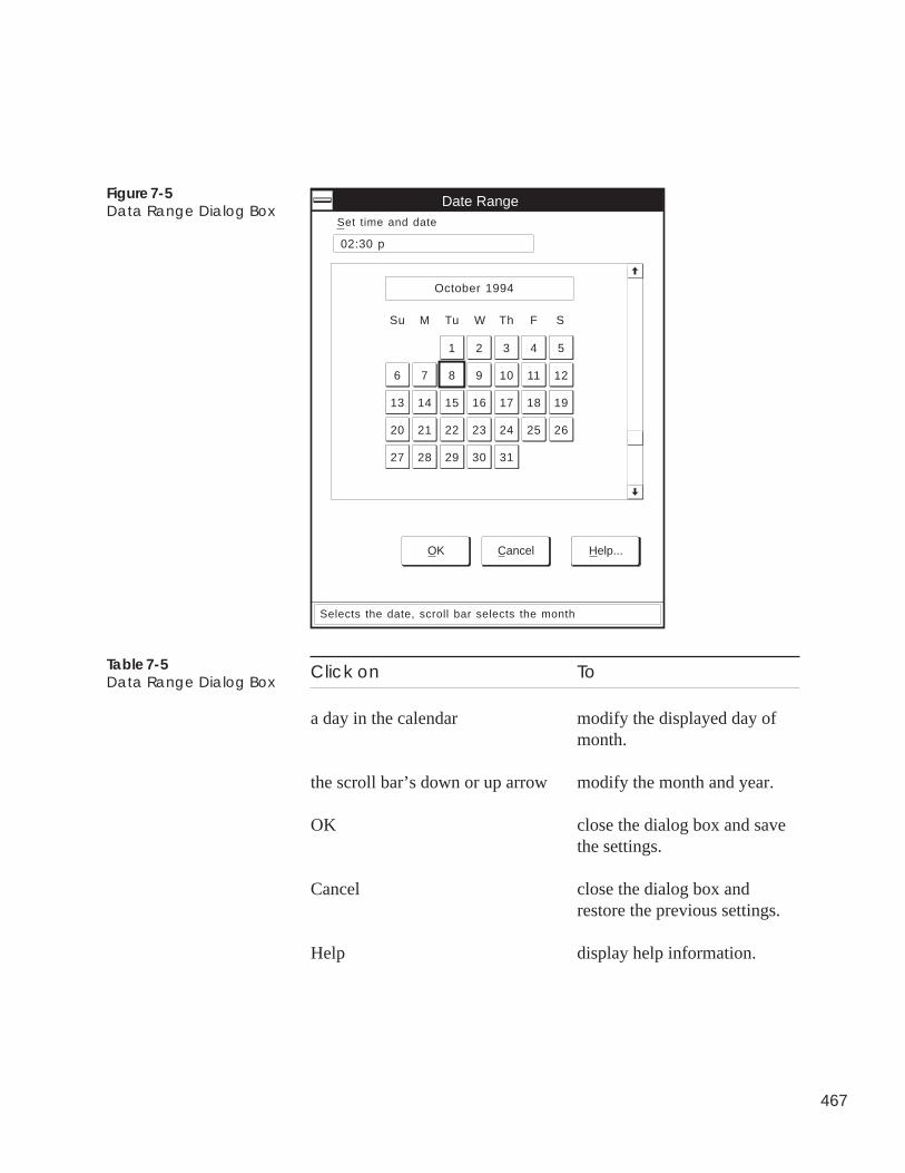
467
Click on To
a day in the calendar modify the displayed day ofmonth.
the scroll bar’s down or up arrow modify the month and year.
OK close the dialog box and savethe settings.
Cancel close the dialog box andrestore the previous settings.
Help display help information.
Figure 7-5Data Range Dialog Box
Table 7-5Data Range Dialog Box
Date Range
OK Cancel Help...
October 1994
Su
1 2 3 4 5
6 7 8 9 10 11 12
19181716151413
20 21 22 23 24 25 26
3130292827
M Tu W Th F S
Selects the date, scroll bar selects the month
Set time and date
02:30 p
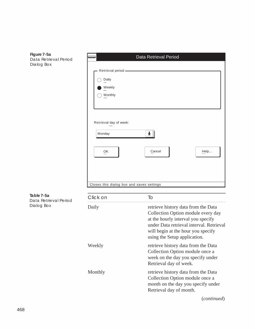
468
Figure 7-5aData Retrieval PeriodDialog Box
Click on To
Daily retrieve history data from the DataCollection Option module every dayat the hourly interval you specifyunder Data retrieval interval. Retrievalwill begin at the hour you specifyusing the Setup application.
Weekly retrieve history data from the DataCollection Option module once aweek on the day you specify underRetrieval day of week.
Monthly retrieve history data from the DataCollection Option module once amonth on the day you specify underRetrieval day of month.
(continued)
Table 7-5aData Retrieval PeriodDialog Box
Closes this dialog box and saves settings
OK
Monday
Retrieval day of week:
Weekly
Retrieval period
Daily
Monthly
Help...Cancel
Data Retrieval Period
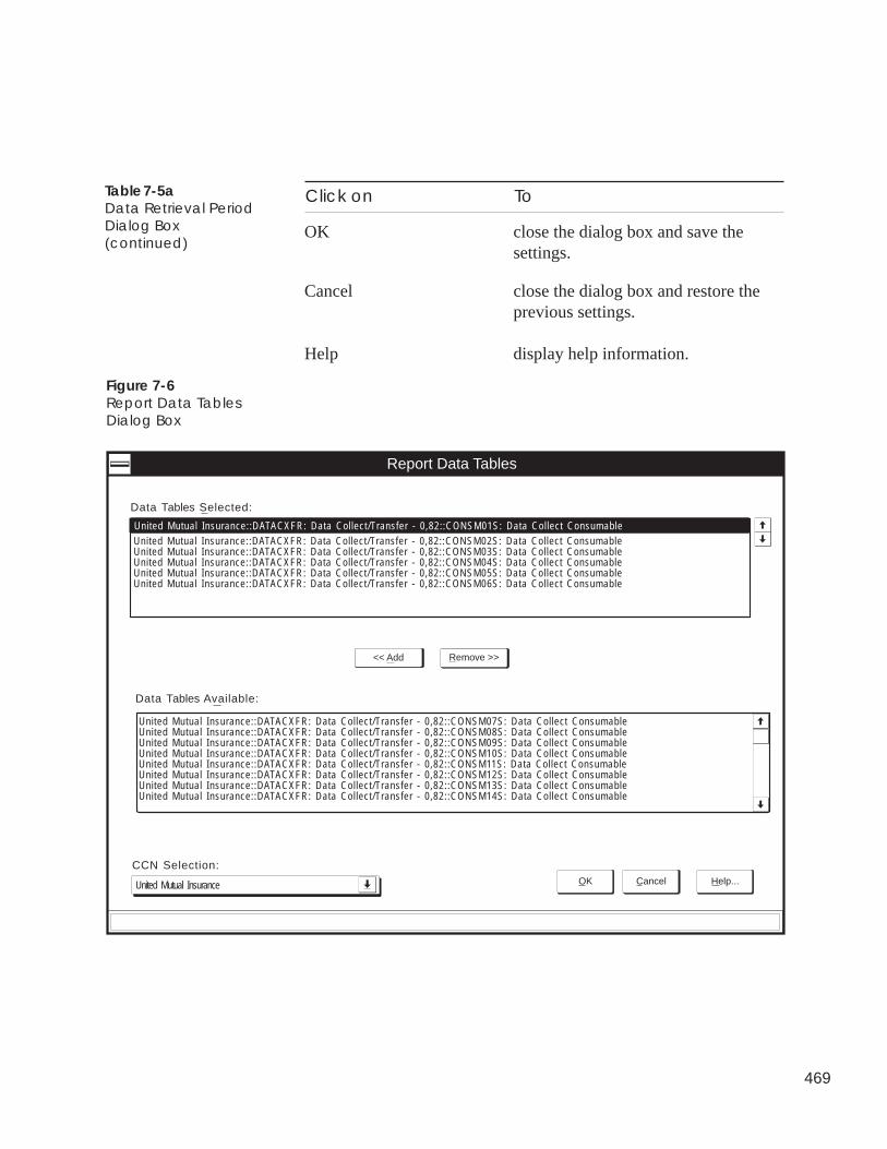
469
OK close the dialog box and save thesettings.
Cancel close the dialog box and restore theprevious settings.
Help display help information.
Click on ToTable 7-5aData Retrieval PeriodDialog Box(continued)
Figure 7-6Report Data TablesDialog Box
Report Data Tables
CCN Selection:
United Mutual Insurance
Data Tables Selected:
Data Tables Available:
OK Cancel Help...
<< Add Remove >>
United Mutual Insurance::DATACXFR: Data Collect/Transfer - 0,82::CONSM02S: Data Collect ConsumableUnited Mutual Insurance::DATACXFR: Data Collect/Transfer - 0,82::CONSM03S: Data Collect ConsumableUnited Mutual Insurance::DATACXFR: Data Collect/Transfer - 0,82::CONSM04S: Data Collect ConsumableUnited Mutual Insurance::DATACXFR: Data Collect/Transfer - 0,82::CONSM05S: Data Collect ConsumableUnited Mutual Insurance::DATACXFR: Data Collect/Transfer - 0,82::CONSM06S: Data Collect Consumable
United Mutual Insurance::DATACXFR: Data Collect/Transfer - 0,82::CONSM01S: Data Collect Consumable
United Mutual Insurance::DATACXFR: Data Collect/Transfer - 0,82::CONSM07S: Data Collect ConsumableUnited Mutual Insurance::DATACXFR: Data Collect/Transfer - 0,82::CONSM08S: Data Collect ConsumableUnited Mutual Insurance::DATACXFR: Data Collect/Transfer - 0,82::CONSM09S: Data Collect ConsumableUnited Mutual Insurance::DATACXFR: Data Collect/Transfer - 0,82::CONSM10S: Data Collect ConsumableUnited Mutual Insurance::DATACXFR: Data Collect/Transfer - 0,82::CONSM11S: Data Collect ConsumableUnited Mutual Insurance::DATACXFR: Data Collect/Transfer - 0,82::CONSM12S: Data Collect ConsumableUnited Mutual Insurance::DATACXFR: Data Collect/Transfer - 0,82::CONSM13S: Data Collect ConsumableUnited Mutual Insurance::DATACXFR: Data Collect/Transfer - 0,82::CONSM14S: Data Collect Consumable
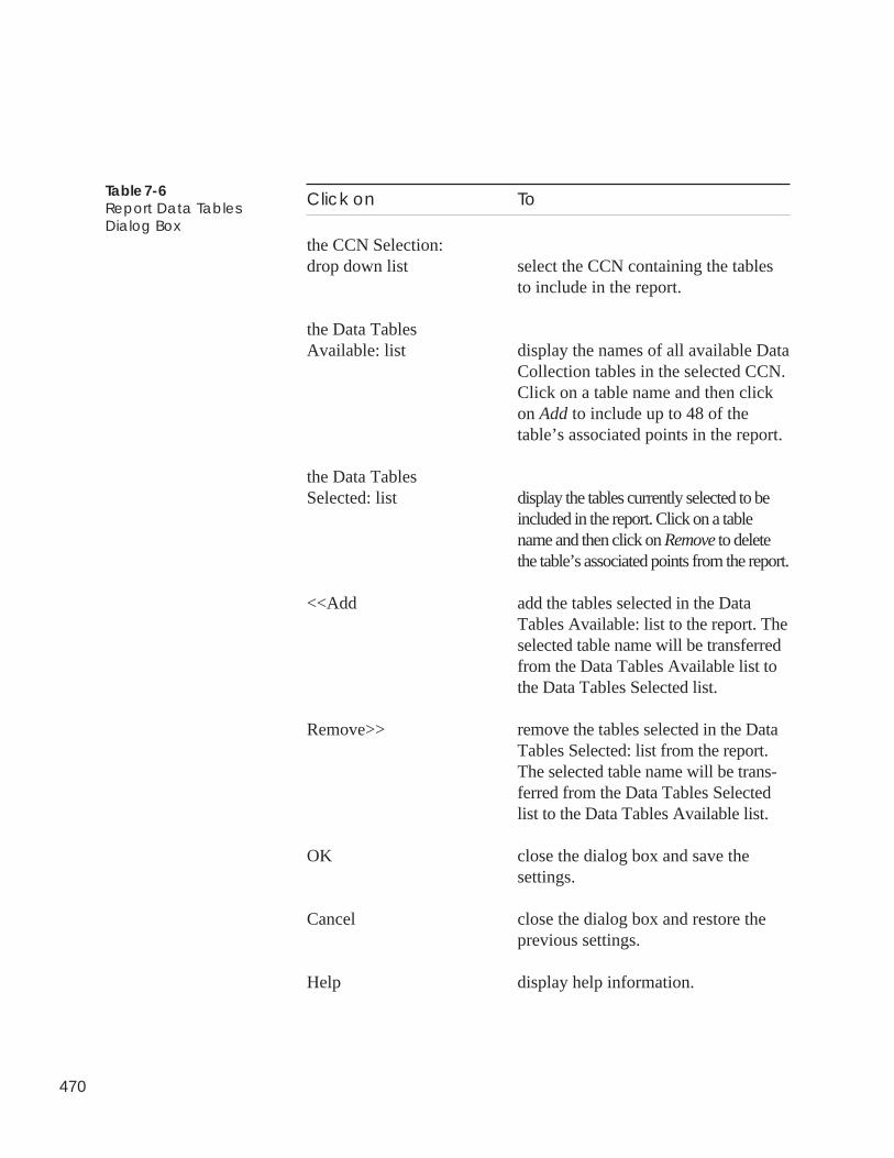
470
Click on To
the CCN Selection:drop down list select the CCN containing the tables
to include in the report.
the Data TablesAvailable: list display the names of all available Data
Collection tables in the selected CCN.Click on a table name and then clickon Add to include up to 48 of thetable’s associated points in the report.
the Data TablesSelected: list display the tables currently selected to be
included in the report. Click on a tablename and then click on Remove to deletethe table’s associated points from the report.
<<Add add the tables selected in the DataTables Available: list to the report. Theselected table name will be transferredfrom the Data Tables Available list tothe Data Tables Selected list.
Remove>> remove the tables selected in the DataTables Selected: list from the report.The selected table name will be trans-ferred from the Data Tables Selectedlist to the Data Tables Available list.
OK close the dialog box and save thesettings.
Cancel close the dialog box and restore theprevious settings.
Help display help information.
Table 7-6Report Data TablesDialog Box
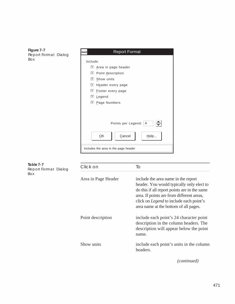
471
Figure 7-7Report Format DialogBox
Click on To
Area in Page Header include the area name in the reportheader. You would typically only elect todo this if all report points are in the samearea. If points are from different areas,click on Legend to include each point’sarea name at the bottom of all pages.
Point description include each point’s 24 character pointdescription in the column headers. Thedescription will appear below the pointname.
Show units include each point’s units in the columnheaders.
(continued)
Table 7-7Report Format DialogBox
Report Format
Include:
OK Cancel Help...
Includes the area in the page header
Area in page header
X
Point description
X
Show units
X
Header every page
X
Footer every page
X
Legend
X
Page Numbers
X
Points per Legend: 4
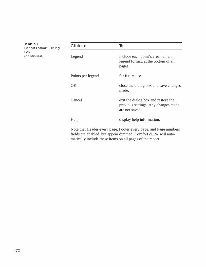
472
Click on To
Legend include each point’s area name, inlegend format, at the bottom of allpages.
Points per legend for future use.
OK close the dialog box and save changesmade.
Cancel exit the dialog box and restore theprevious settings. Any changes madeare not saved.
Help display help information.
Note that Header every page, Footer every page, and Page numbersfields are enabled, but appear dimmed. ComfortVIEW will auto-matically include these items on all pages of the report.
Table 7-7Report Format DialogBox(continued)
473
The report definition shown in Figure 7-8 will generate a historyreport named ZONETEMP, which is used for zone temperaturetracking. In this example, it is assumed that today is October 24,1996 and ComfortVIEW is configured to automatically andperiodically retrieve data from the network’s Data CollectionOption Module. This report definition will automatically gener-ate the ZONETEMP history report once a day. This definitionwill also create a report, on manual command, using the mostup-to-the-minute zone temperature data that it can retrieve fromthe network.
Automatic Retrieval Options: The zone temperature history datawill be automatically retrieved from the Data Collection OptionModule every two hours as was specified in the Data RetrievalPeriod dialog box, which was accessed by clicking on the Dataretrieval period button. An actual report, based on the retrieveddata, will be automatically generated, once a day, and will beprinted to a printer named HP LaserJet III. The time of day thatthe report will generate is 2:00 am. This information has beenspecified using the ComfortVIEW Setup application.
Manual Generation Options: When the report is generated oncommand by a user, the latest up-to-the-minute data will beretrieved from the Data Collection Option Module. This manu-ally-generated report will be presented on the screen for userviewing. Since the Range of Data has been configured to in-clude all of yesterday’s as well as today’s data, the report willinclude data from the previous day’s automatic retrieval activity.
Sample History ReportExplanation
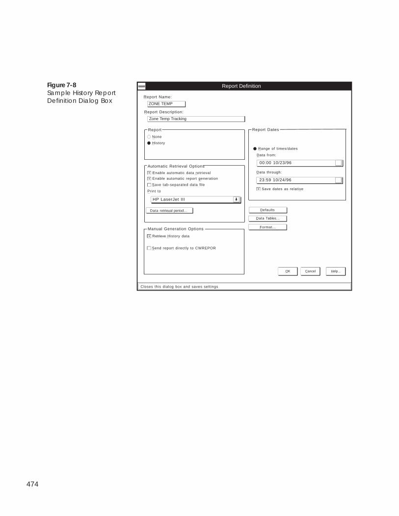
474
Figure 7-8Sample History ReportDefinition Dialog Box
Enable automatic data retrieval
History
Report Definition
Report Name:
OK Cancel Help...
X
None
Format...
Defaults
HP LaserJet III
ZONE TEMP
Report Description:
Zone Temp Tracking
Report
Save tab-separated data file
Print to
XEnable automatic report generation
Send report directly to CWREPOR
Retrieve History data
Manual Generation Options
00:00 10/23/96
Data from:
Range of times/dates
Report Dates
23:59 10/24/96
Data through:
Save dates as relative
X
X
Automatic Retrieval Options
Closes this dialog box and saves settings
Data Tables...
Data retrieval period...
475
The report definition shown in Figure 7-9 will generate a con-sumable report named METER1A, which is used for trackingbuilding energy usage. In this example, it is assumed that todayis October 24, 1996 and ComfortVIEW is configured to auto-matically retrieve daily consumable data from the network’sData Collection Option Module. This report definition willautomatically generate the METER1A consumable report once aday. This definition will also create a report, on manual com-mand, using the most up-to-date consumable data that it canretrieve from the network.
Automatic Retrieval Options: The consumable data will beautomatically retrieved from the Data Collection Option Module.An actual report, based on the retrieved data, will be automati-cally generated, once a day, and will be printed to a printernamed HP LaserJet III. The time of day that the report willgenerate is 2:00 am. This information has been specified usingthe ComfortVIEW Setup application.
Manual Generation Options: When the report is generated oncommand by a user, the most up-to-date consumable data will beretrieved from the Data Collection Option Module. This manu-ally-generated report will be sent directly to the CWREPORTprinter. Since the Range of Data has been configured to includeall of yesterday’s as well as today’s data, the report will includedata from yesterday’s automatic retrieval activity.
Sample ConsumableReport Explanation

476
Figure 7-9Sample ConsumableReport Definition DialogBox
Daily
Monthly
Report Definiton
Report Name:
OK Cancel Help...
X
None
Format...
Data Tables...
Defaults
LaserJet III
METER1A
Report Description:
Building Meter Summary
Yearly
Report
Save tab-separated data file
Print to
XEnable automatic report generation
Send report directly to CWREPORT printer
Retrieve Yesterday's data
Manual Generation Options
Retrieve Today's data
00:00 10/22/96
Data from:
Today
Range of data
Yesterday
Report Dates
23:59 10/23/96
Data through:
Save dates as relative
X
X
X
Closes this dialog box and saves settings
Automatic Retrieval Options
Enable automatic data retrieval
477
The report definition shown in Figure 7-10 will generate aruntime report named SUPFANS, which is used for accumulat-ing the run time of a building’s air handler supply fans. In thisexample it is assumed that today is October 25, 1996 andComfortVIEW is configured to automatically retrieve daily datafrom the network’s Data Collection Option Module in anticipa-tion of creating a monthly report. This report definition will notautomatically generate a report every day. It will automaticallyretrieve the data, however. The report definition permits themanual generation of a monthly report based on the month’saccumulated data.
Automatic Retrieval Options: The runtime data will be auto-matically retrieved from the Data Collection Option Module.The retrieval time of day has been specified using theComfortVIEW Setup application.
Manual Generation Options: When the report is generated oncommand by a user, the included runtime data will include datafor the current month through yesterday. No data retrieval willtake place on the generation of the monthly report. This reportwill be presented to the user by means of the report viewer. Itwill not be sent directly to the CWREPORT printer.
Sample Runtime ReportExplanation

478
Figure 7-10Sample Runtime ReportDefinition Dialog Box
Daily
Monthly
Report Definiton
Report Name:
OK Cancel Help...
X
None
Format...
Data Tables...
Defaults
LaserJet III
SUPFANS
Report Description:
Supply Fan Runtimes
Yearly
Report
Save tab-separated data file
Print to
Enable automatic report generation
Send report directly to CWREPORT printer
Retrieve Yesterday's data
Manual Generation Options
Retrieve Today's data
00:00 10/24/96
Data from:
Today
Range of data
Yesterday
Report Dates
23:59 10/24/96
Data through:
Save dates as relative
X
Closes this dialog box and saves settings
Automatic Retrieval Options
Enable automatic data retrieval
479
Follow the instructions below to delete a report definition from thereport definition list.
Deleting a report definition deletes the definition only. The reportdefinition deletion process does not delete any related report filesthat you may have saved.
1. Display the report definition list. If necessary, refer to Dis-playing the Report Definition List.
2. Click on the report definition you wish to delete.
Note: ComfortVIEW allows you to delete multiple reportdefinitions. Use the Windows-standard mouse orkeyboard techniques to select multiple definitions.
3. Click on the Edit menu item and then click on Delete.
Note: You may also perform this command by clicking onDelete icon in the toolbar.
ComfortVIEW displays the following prompt: Reconfigurethe data collection tables?
4. Click on Yes to free up any data collection tables that havebeen assigned to this report, or on No to prevent tabledeallocation from taking place.
You would typically select No if you wish to keep the tablesin a Data Collection Option for later use, or if the tables arein a GPM or HPM and cannot be deallocated.
Note: ComfortVIEW will not deallocate any data collec-tion tables that are being used by other reportdefinitions.
You will then be presented with a deletion confirmationdialog box.
5. Click on Yes to complete the deletion or click on No toprevent the deletion from taking place. If you have selectedmultiple definitions and wish to delete all, click on Yes to All.
ComfortVIEW displays a function status box during thedeletion, and the report definition list re-displays when thedeletion is complete.
Deleting anExisting
Report Definition
480
Follow the steps below to print a selected report definition.
1. Display the report definition list. If necessary, refer to Dis-playing the Report Definition List.
2. Click on the report definition you wish to print.
3. Click on the File menu item and then click on Print.
Note: You may also perform this command by clicking onthe Print icon.
ComfortVIEW opens the Windows Notepad application and dis-plays the report definition information.
To print the Report Definition:
Click on Notepad’s File menu item and then click on Print.
To close the report:
Click on Notepad’s File menu item and then click on Exit.
You can change the report definition list font. When you change thefont, all report definition list text is affected.
To change the font:
1. Display the report definition list. If necessary, refer to Dis-playing the Report Definition List.
2. Click on the Options menu item followed by clicking on Font.
ComfortVIEW displays the Font dialog box. Refer to Figure7-11.
3. In the Font box, select the font you want to use.
The text in the Sample box changes to reflect the font youselect.
4. In the Font Style box, select any style options you want to use(for example, bold or italic).
5. In the Size box, select the point size you want to use: thelarger the point size, the larger the characters appears on yourscreen.
6. Click on OK.
Printing aReport
Definition
Changing the Font
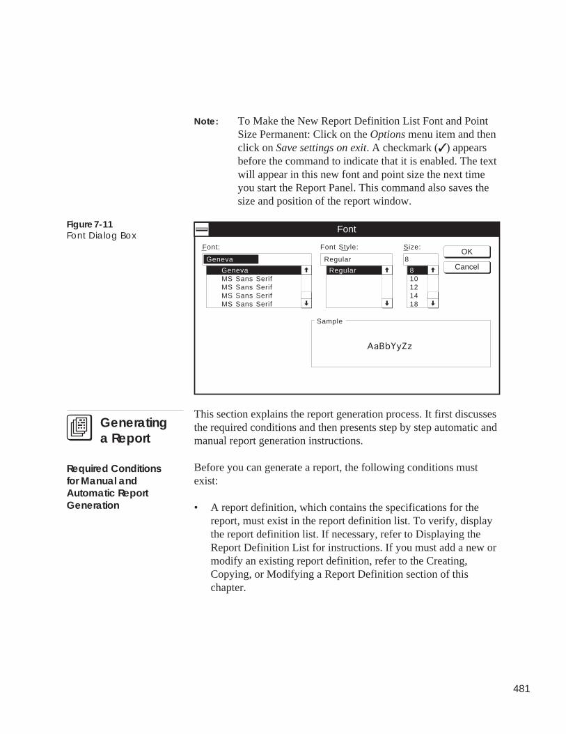
481
Note: To Make the New Report Definition List Font and PointSize Permanent: Click on the Options menu item and thenclick on Save settings on exit. A checkmark (✓ ) appearsbefore the command to indicate that it is enabled. The textwill appear in this new font and point size the next timeyou start the Report Panel. This command also saves thesize and position of the report window.
Figure 7-11Font Dialog Box
8
8
Font:
Font
Sample
Font Style: Size:
GenevaMS Sans SerifMS Sans SerifMS Sans SerifMS Sans Serif
Regular
Regular10121418
AaBbYyZz
GenevaOK
Cancel
This section explains the report generation process. It first discussesthe required conditions and then presents step by step automatic andmanual report generation instructions.
Before you can generate a report, the following conditions mustexist:
• A report definition, which contains the specifications for thereport, must exist in the report definition list. To verify, displaythe report definition list. If necessary, refer to Displaying theReport Definition List for instructions. If you must add a new ormodify an existing report definition, refer to the Creating,Copying, or Modifying a Report Definition section of thischapter.
Required Conditionsfor Manual andAutomatic ReportGeneration
Generatinga Report
482
• To generate a consumable, runtime, or history report, a DataCollection Module must exist on the Carrier Comfort Network.The module also must have been added to the ComfortVIEWdatabase. For instructions on adding system elements to thedatabase, refer to the Adding/Modifying Controllers section ofthis manual’s Carrier Network Manager chapter.
• For consumable, runtime, and history reports, a report table mustexist and must be configured in the Data Collection Option. (Forexample, if the Data Collection Option is collecting runtimedata, you must configure the Data Collection Option’sRUNTMxxS Table.) For instructions on configuring Data Col-lection Option tables, refer to Displaying and Configuring CCNOptions in the Carrier Network Manager chapter of this manual.
• For consumable and runtime points in PICs or Comfort Control-lers, an equipment part report table must also exist and beconfigured in the PIC or Comfort Controller. (For example, ifthe Data Collection Option is collecting runtime data from the39N Air Handler PIC, you must also configure the 39N’sRuntime Configuration Table.) If necessary, refer to the Modify-ing Configuration Table Values or Configuring Comfort Con-trollers section of the Carrier Network Manager chapter of thismanual.
• When generating reports for remote CCNs, ComfortVIEW willautomatically connect to the remote CCN to retrieve data. YourAutodial Gateway must be capable of connecting to the remoteCCN when commanded by ComfortVIEW.
Note: This will only happen if your report definition calls forthe retrieval of data to create the report. If you plan touse data that has already been been retrieved and storedin the ComfortVIEW database, remote CCN connectionis not necessary.
• If you wish to print the report, you must create a printer calledCWREPORT in the Windows NT Print Manager. Manually-generated reports will print to this printer. Automatically-generated reports will print to the printer you select in theReport Definition dialog box.
483
Follow the steps below to produce a report on request.
1. Verify that the Required Conditions for Manual and AutomaticReport Generation exist.
2. Display the report definition list. If necessary, refer to Display-ing the Report Definition List.
3. Click on the report definition from which you wish to create areport.
Note: If desired, you can review the report specifications bydouble clicking on the report definition. The ReportDefinition dialog box will display. Modify specifica-tions as desired. Click on OK to save the modifications,or click on Cancel to exit without saving changes.
Be aware that changes made to the Report Dates options willaffect any automatic generation. Remember to return the ReportDates to their original settings.
4. Click on the File menu item and then click on Generate.
ComfortVIEW displays a confirmation dialog box asking if youwish to generate the report.
5. Click on Yes to generate the report or click on No to preventreport generation. If you have selected multiple reports and wishto generate all, click on Yes to All.
A function status box is displayed during the report generation.
If, in the Report Definition dialog box, you enabled the Sendreport directly to CWREPORT printer option, the report printson the CWREPORT printer created in the Windows NT PrintManager, and the report definition list re-displays on completion.Refer to the end of this chapter for sample ComfortVIEW re-ports.
If you did not enable the Send report directly to CWREPORTprinter option, ComfortVIEW initiates the report viewer anddisplays the report on-screen. For instructions on the ReportPanel’s report viewer function, refer to the Using the ReportViewer section of this chapter.
To Manually Generatea Report
484
You can also use the File menu's Regenerate command (or click onthe Regenerate icon in the toolbar) to manually reproduce a selectedreport based on a range of dates that is different than those specifiedin the report definition.
Follow the steps below to automatically produce a report at a user-specified time.
1. Verify that the Required Conditions for Manual and Auto-matic Report Generation exist.
2. Display the report definition list. If necessary, refer to Dis-playing the Report Definition List.
3. Configure your report definition to automatically retrieve dataand automatically generate a report. For instructions, refer toModifying an Existing Report Definition in the Creating,Copying, or Modifying a Report Definition section of thischapter.
4. The report will automatically generate and print at the timespecified in the ComfortVIEW Setup application. If you wishto view or modify this time, refer to this manual’s Setupchapter for instructions. The report will print on the printerspecified in the Report Definition dialog box’s Print to dropdown list. This list appears under Automatic Retrieval Op-tions.
If bad data is encountered when a daily time-based report (i.e.,History, Runtime, or Consumable) is being generated,ComfortVIEW will indicate the reason for the bad data on the reportin the status column to the right of the data. Bad data may be en-countered for the following reasons:
• no data was available from the controller
• there was a communication failure within the CCN
• there was a hardware failure at the controller
Manual Report
Regeneration
To AutomaticallyGenerate a Report
Report Data Status
485
• the data collection option was configured improperly
• there was a mismatch of information between the ComfortVIEWdatabase and the Data Collection Option.
When bad data is encountered in a daily time-based report, it isdiscarded and ComfortVIEW provides an interpolated value for thattime instead. The interpolated value is calculated using the averageof the good data readings preceding and succeeding the bad data.Interpolated values are inserted if up to two consecutive data read-ings are bad. If bad data exists for more than two data readings, nointerpolation is performed, and the data is included in the report.
The report viewer function gives you the capability to:
• view, print, and save a report on disk.
• display another previously-generated report file.
The report viewer is automatically invoked as part of manual reportgeneration. You can also, however, manually initiate the reportviewer by clicking on the report definition list's File menu item andthen clicking on Report Viewer.
Note: In Windows 9x client, it is recommended that you do notopen more than one instance of the Report Viewer application. Thisis in order to conserve system resources.
When it is invoked by manual report generation, the report viewerfunction consists of a Report Viewer window with a Print Previewmode. The Print Preview mode is activated automatically when youmanually generate a report and disable the Report Definition dialogbox’s Send report directly to CWREPORT printer option. When youexit the Print Preview mode, the Report Viewer window is dis-played.
When you manually generate a report, the report viewer displays thereport in front of you in a Print Preview mode. This gives you theopportunity to view the report before you print it. A sample PrintPreview window is displayed in Figure 7-12.
Using the ReportViewer
Print Preview Mode
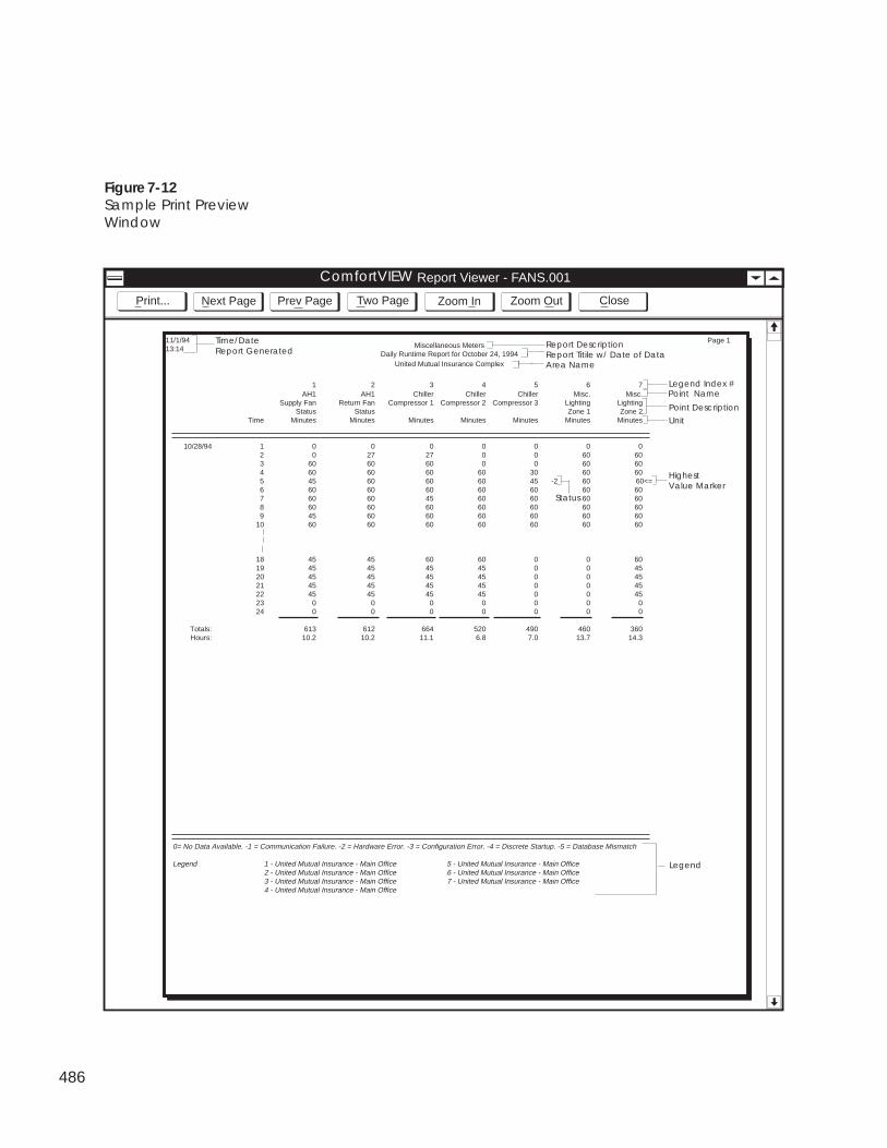
486
Figure 7-12Sample Print PreviewWindow
ComfortWorks Report Viewer - FANS.001
Zoom OutZoom In CloseTwo PagePrev PageNext PagePrint...
Miscellaneous MetersDaily Runtime Report for October 24, 1994
United Mutual Insurance Complex
1 2 3 4 5 6 7AH1 AH1 Chiller Chiller Chiller Misc. Misc.
Supply Fan Return Fan Compressor 1 Compressor 2 Compressor 3 Lighting LightingStatus Status Zone 1 Zone 2
Time Minutes Minutes Minutes Minutes Minutes Minutes Minutes
10/28/94 1 0 0 0 0 0 0 02 0 27 27 0 0 60 603 60 60 60 0 0 60 604 60 60 60 60 30 60 605 45 60 60 60 45 -2 60 60<=6 60 60 60 60 60 60 607 60 60 45 60 60 60 608 60 60 60 60 60 60 609 45 60 60 60 60 60 60
10 60 60 60 60 60 60 60
18 45 45 60 60 0 0 6019 45 45 45 45 0 0 4520 45 45 45 45 0 0 4521 45 45 45 45 0 0 4522 45 45 45 45 0 0 4523 0 0 0 0 0 0 024 0 0 0 0 0 0 0
Totals: 613 612 664 520 490 460 360Hours: 10.2 10.2 11.1 6.8 7.0 13.7 14.3
0= No Data Available. -1 = Communication Failure. -2 = Hardware Error. -3 = Configuration Error. -4 = Discrete Startup. -5 = Database Mismatch
Legend 1 - United Mutual Insurance - Main Office 5 - United Mutual Insurance - Main Office2 - United Mutual Insurance - Main Office 6 - United Mutual Insurance - Main Office3 - United Mutual Insurance - Main Office 7 - United Mutual Insurance - Main Office4 - United Mutual Insurance - Main Office
11/1/9413:14
Area NameReport Titile w/ Date of DataReport Description
Unit
Time/DateReport Generated
Page 1
Point Description
Point NameLegend Index #
HighestValue Marker
Legend
Status
ComfortVIEW
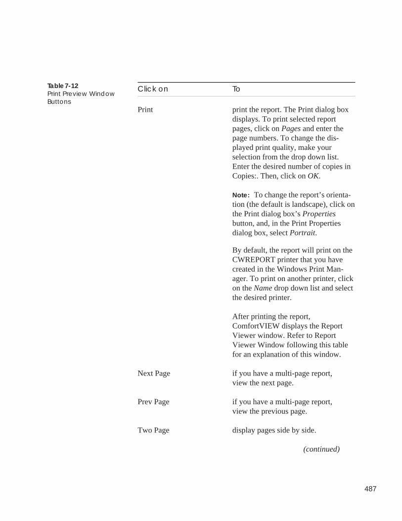
487
Click on To
Print print the report. The Print dialog boxdisplays. To print selected reportpages, click on Pages and enter thepage numbers. To change the dis-played print quality, make yourselection from the drop down list.Enter the desired number of copies inCopies:. Then, click on OK.
Note: To change the report’s orienta-tion (the default is landscape), click onthe Print dialog box’s Propertiesbutton, and, in the Print Propertiesdialog box, select Portrait.
By default, the report will print on theCWREPORT printer that you havecreated in the Windows Print Man-ager. To print on another printer, clickon the Name drop down list and selectthe desired printer.
After printing the report,ComfortVIEW displays the ReportViewer window. Refer to ReportViewer Window following this tablefor an explanation of this window.
Next Page if you have a multi-page report,view the next page.
Prev Page if you have a multi-page report,view the previous page.
Two Page display pages side by side.
(continued)
Table 7-12Print Preview WindowButtons
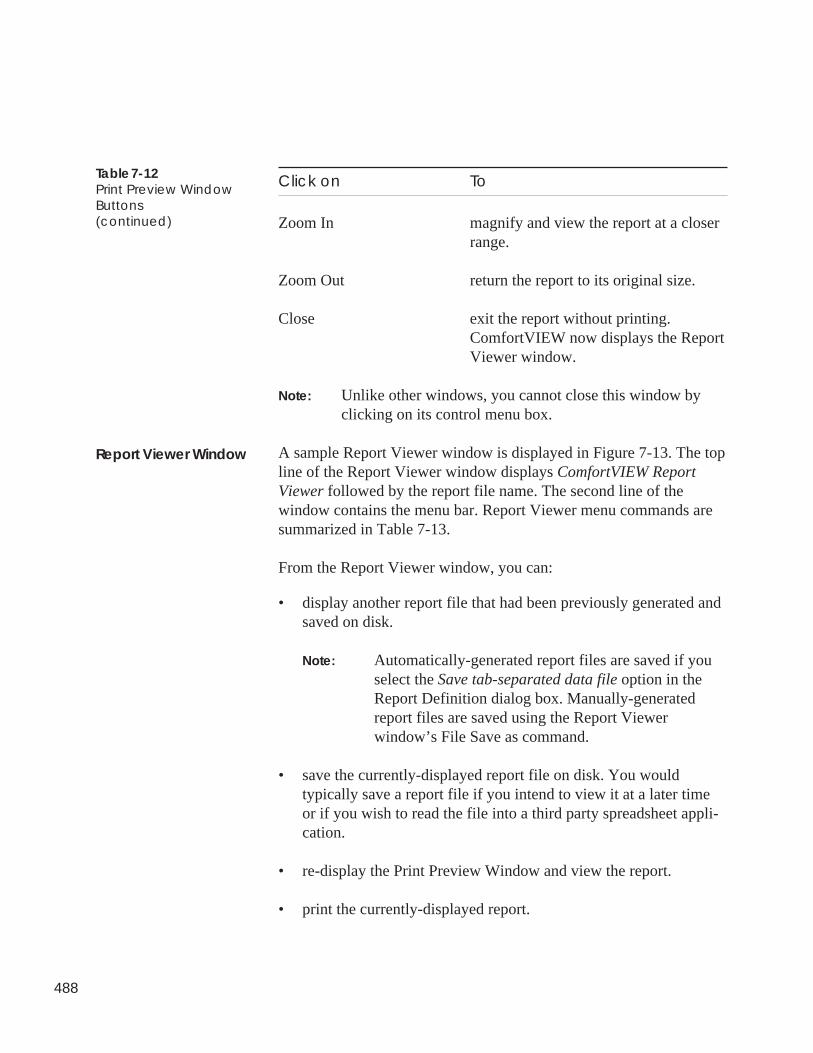
488
Table 7-12Print Preview WindowButtons(continued)
Click on To
Zoom In magnify and view the report at a closerrange.
Zoom Out return the report to its original size.
Close exit the report without printing.ComfortVIEW now displays the ReportViewer window.
Note: Unlike other windows, you cannot close this window byclicking on its control menu box.
A sample Report Viewer window is displayed in Figure 7-13. The topline of the Report Viewer window displays ComfortVIEW ReportViewer followed by the report file name. The second line of thewindow contains the menu bar. Report Viewer menu commands aresummarized in Table 7-13.
From the Report Viewer window, you can:
• display another report file that had been previously generated andsaved on disk.
Note: Automatically-generated report files are saved if youselect the Save tab-separated data file option in theReport Definition dialog box. Manually-generatedreport files are saved using the Report Viewerwindow’s File Save as command.
• save the currently-displayed report file on disk. You wouldtypically save a report file if you intend to view it at a later timeor if you wish to read the file into a third party spreadsheet appli-cation.
• re-display the Print Preview Window and view the report.
• print the currently-displayed report.
Report Viewer Window
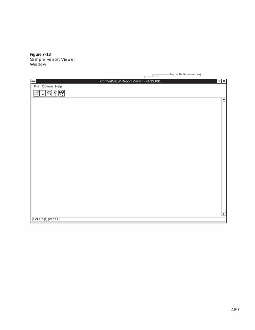
489
Figure 7-13Sample Report ViewerWindow
Report File Name (Active)
ComfortVIEW Report Viewer - FANS.001
File Options
For Help, press F1
Help
490
File MenuCommands Use this command to
Open display another report file.
Note: This report file must have beenpreviously generated and saved to disk.
The File Open dialog box displays.Select the file you wish to display ortype the file name in the File Namebox. You can also select a differentdrive by making your selection fromthe Drives drop down list. You canselect a report file that is resident onanother network computer by clickingon the Network button. ComfortVIEWsaves automatically-generated reportsto the \REPORTS\report type directorypath (where report type is replaced bythe type of report being generated:CONSUME, HISTORY, RUNTIME,etc.). This directory path will belocated in \CWORKS, \CVIEW, orother directory in which you installedComfortVIEW. ComfortVIEW usesthe following report file naming con-vention: Rptname.xxx (whereRptname is replaced by the 8 charactername you enter in the Report Nametext box, and xxx is the report numberranging from 001 to 999. Note that thisnumber is incremented each time youre-generate this report.)
(continued)
Table 7-13Report Viewer MenuCommands
491
File MenuCommands Use this command to
Save As save the currently-displayed reportfile. The name of the currently-displayed report appears in the topline of the window followingComfortVIEW Report Viewer -.
The File Save As dialog box displays.To save the file with a name differentfrom the one displayed in the FileName box, type the name for the file.You may also select a different driveand a different directory or folder. Foryour convenience, a \REPORTSdirectory is supplied on your disk.This directory will be located in the\CWORKS, \CVIEW, or other direc-tory in which you installedComfortVIEW. To save the file onanother network computer, click onthe Network button.
Print print the currently displayed reportfile. The name of the currently-displayed report appears in the topline of the window followingComfortVIEW Report Viewer -.
The Print dialog box displays. Toprint selected report pages, click onPages and enter the page numbers. Tochange the displayed print quality,make your selection from the dropdown list. Enter the desired number ofcopies in Copies:, and, if desired,click on Collate Copies. Click on OK.
(continued)
Table 7-13Report Viewer MenuCommands(continued)
492
Table 7-13Report Viewer MenuCommands(continued)
File MenuCommands Use this command to
Print (continued) Note: If you wish to change thereport’s orientation (the default islandscape), click on the Print dialogbox’s Properties button, and, in thePrint Properties dialog box, selectPortrait.
By default, the report will print on theCWREPORT printer created in theWindows NT Print Manager. If youwish to print on another printer, clickon the Name drop down list and selecta printer.
Print Preview return to the Print Preview Windowand view the report.
Print Setup override the CWREPORT printerassignment. By default, manually-generated reports print on this printer,which is created in the Windows NTPrint Manager. Selecting thiscommand allows you to override theCWREPORT printer assignment.
The Print Setup dialog box displays. Ifyou wish to change the printer fromthe one displayed, select from the dropdown lists. Click on Portrait orLandscape to select the report’sorientation. If you wish to selectanother network printer, click on theNetwork button, and, in the Connect toPrinter dialog box, select a printer.
(continued)
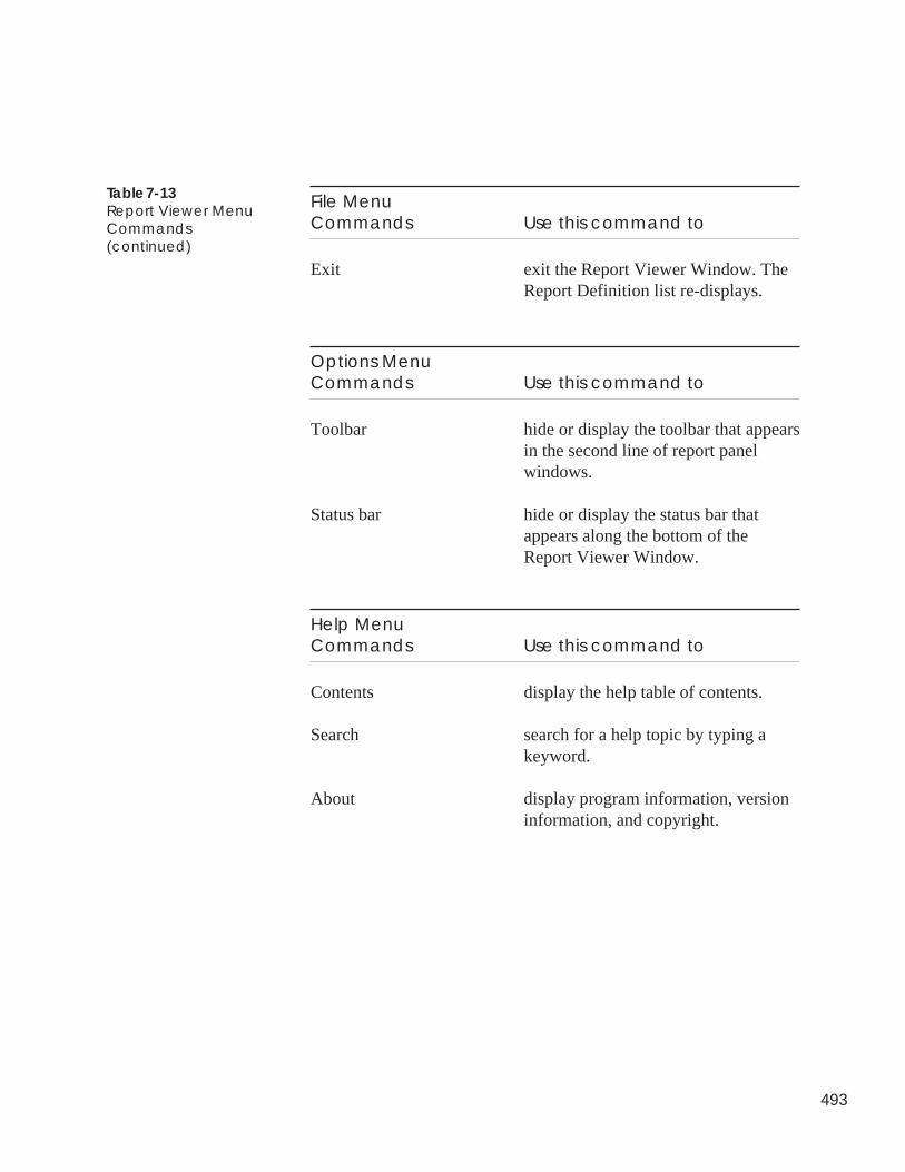
493
File MenuCommands Use this command to
Exit exit the Report Viewer Window. TheReport Definition list re-displays.
Options MenuCommands Use this command to
Toolbar hide or display the toolbar that appearsin the second line of report panelwindows.
Status bar hide or display the status bar thatappears along the bottom of theReport Viewer Window.
Help MenuCommands Use this command to
Contents display the help table of contents.
Search search for a help topic by typing akeyword.
About display program information, versioninformation, and copyright.
Table 7-13Report Viewer MenuCommands(continued)
494
Editing ReportData
ComfortVIEW gives you the ability to modify the consumable andruntime and tenant billing data that it retrieves from the Data Collec-tion and Tenant Billing Options and stores in its database.
Specifically, if there are missing or erroneous daily values in yourmonthly data, you can insert the missing or modify the existing dailyvalues by following the instructions below. ComfortVIEW thenautomatically updates your monthly and yearly totals accordingly.
To edit your report data:
• Use the Windows Notepad application to create a text file con-taining the new or modified daily values. For instructions, referbelow to To Create the Text File.
• Display the report definition list and use the File menu’s Importdata command to import the Notepad text file into theComfortVIEW database. If you are modifying existing dailytotals, the text file data will overwrite the existing values. If youare inserting missing daily totals, the text file data will be insertedinto the monthly data. The monthly and yearly data will automati-cally update accordingly. For instructions on importing theNotepad text file, refer below to To Import the Data into theConsumable. Runtime, or Tenant Billing Data File.
1. Use the Windows Notepad application to create a file with thenew or modified data.
Note: You must type each line of data in the format shownbelow. Separate each piece of data with a Tab.
For Consumable and Runtime Data:Year [Tab] Month [Tab] Day [Tab] Numeric Value [Tab] Index #
where:Year = the 4 digit year (Ex: 1999); Month = 1-12; Day = 1-31;Numeric Value = the daily valueIndex # = 0 (Consumable) 1-8 (Runtime Index #)
For Tenant Billing Data:Year [Tab] Month [Tab] Day [Tab] Hour [Tab] Minute [Tab] Zone#[Tab] Name [Tab] Duration
where:Year = the 4 digit year (Ex: 1999); Month = 1-12; Day = 1-31;Hour = 1-24; Minute = 1-60; Zone# = the tenant billing zone;Name = the zone name; Duration = time in minutes
To Create the Text File
495
2. Save the Notepad text file in the directory\CVIEW\REPORTS using the .RPT file extension.Example Notepad text file containing consumable data:EXAMPLE.RPT
1994 9 1 21113.2567 0
Explanation:When this text file is imported, the existing daily consumabletotal usage value for 9/1/94 will be overwritten with the value21113.2567. If there currently is no usage value for this date,this value will be inserted into the monthly data. It will thenbe added to the 9/94 monthly total. The 94 yearly total alsowill be adjusted accordingly.
1. Display the report definition list. If necessary, refer to Dis-playing the Report Definition List.
2. Click on the File menu item and then click on Import data.
ComfortVIEW displays the Data Table Selection dialog box.This dialog box lists all consumable and runtime tables ineach CCN. Refer to Figure 7-14 and Table 7-14 for instruc-tions on using this dialog box.
3. Select a CCN from the Select CCN drop down list.
4. In the Select data table list, select the option table containingthe point whose monthly data you intend to modify and clickon OK.
The Open File dialog box displays.
5. Select the Notepad text file you wish to import or type thetext file name in the File Name box. You can also select adifferent drive by making your selection from the Drives dropdown list. You can select a text file that may be resident onanother network computer by clicking on the Network button.
6. Click on OK.
The dialog box closes, the data imports into the selectedconsumable or runtime file, and the report definition list re-displays.
To Import the Data intothe Consumable,Runtime, or TenantBilling Data File
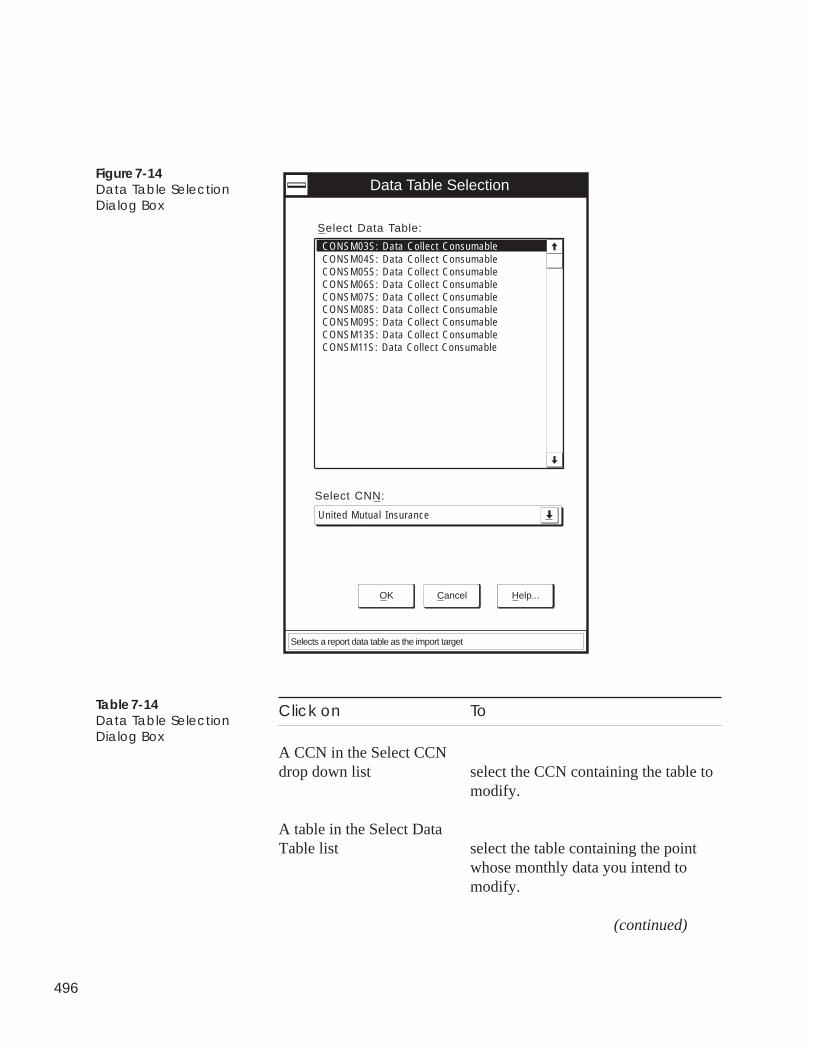
496
Figure 7-14Data Table SelectionDialog Box
Data Table Selection
OK Cancel Help...
Select CNN:
United Mutual Insurance
CONSM03S: Data Collect Consumable
Select Data Table:
CONSM04S: Data Collect ConsumableCONSM05S: Data Collect ConsumableCONSM06S: Data Collect ConsumableCONSM07S: Data Collect ConsumableCONSM08S: Data Collect ConsumableCONSM09S: Data Collect ConsumableCONSM13S: Data Collect ConsumableCONSM11S: Data Collect Consumable
Selects a report data table as the import target
Click on To
A CCN in the Select CCNdrop down list select the CCN containing the table to
modify.
A table in the Select DataTable list select the table containing the point
whose monthly data you intend tomodify.
(continued)
Table 7-14Data Table SelectionDialog Box
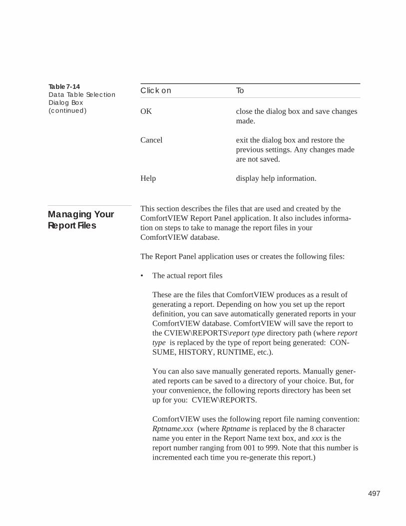
497
Table 7-14Data Table SelectionDialog Box(continued)
Click on To
OK close the dialog box and save changesmade.
Cancel exit the dialog box and restore theprevious settings. Any changes madeare not saved.
Help display help information.
This section describes the files that are used and created by theComfortVIEW Report Panel application. It also includes informa-tion on steps to take to manage the report files in yourComfortVIEW database.
The Report Panel application uses or creates the following files:
• The actual report files
These are the files that ComfortVIEW produces as a result ofgenerating a report. Depending on how you set up the reportdefinition, you can save automatically generated reports in yourComfortVIEW database. ComfortVIEW will save the report tothe CVIEW\REPORTS\report type directory path (where reporttype is replaced by the type of report being generated: CON-SUME, HISTORY, RUNTIME, etc.).
You can also save manually generated reports. Manually gener-ated reports can be saved to a directory of your choice. But, foryour convenience, the following reports directory has been setup for you: CVIEW\REPORTS.
ComfortVIEW uses the following report file naming convention:Rptname.xxx (where Rptname is replaced by the 8 charactername you enter in the Report Name text box, and xxx is thereport number ranging from 001 to 999. Note that this number isincremented each time you re-generate this report.)
Managing YourReport Files
498
To Manage These Report Files:
It is your responsibility to periodically delete or copy report files to adiskette. This is particularly important if you have configured yourComfortVIEW system to automatically generate reports and save themin your database. This action will lead to a steady decrease in availableComfortVIEW disk space.
• The report data that ComfortVIEW retrieves from the CCN optionmodules, stores in the ComfortVIEW database, and uses to formulatereports.
To Manage This Data:
It is your responsibility to specify the number of days thatComfortVIEW will retain retrieved report data in its database. At theend of this retention period, which you specify using ComfortVIEWSetup application, ComfortVIEW automatically deletes the data.
Only retrieved consumable, runtime, and history report data is subjectto this purging. You can generate reports using the retained data untilthe end of this retention period.
Retention period valid entries range from 0 to 99 days. Entering 0causes the data to be retained as long as ComfortVIEW has disk spaceto store it. You are cautioned against doing this, as it could eventuallyconsume all disk space.
• The Notepad text files that you create and import to the ComfortVIEWdatabase in the event that you have missing or incorrect daily reportvalues.
These text files modify the report data that ComfortVIEW retrievesfrom the CCN option modules. (These data files are described in thebulleted item above.)
You must type data into the Notepad text file using the format shownin the Editing Report Data section of this chapter, and save the text filein the directory \CVIEW\REPORTS using the .RPT file extension.
To Manage These Data Files:
You can delete these files once the Import is complete.
499
You can include your own custom report in the Report Panel. Youdo this by adding an icon to the Report Panel window. The iconcould be used, for example, to launch a third party spreadsheetapplication that you could use to manipulate your report data.
Follow the steps below to add a report to ComfortVIEW ReportPanel:
1. Display the report panel. If necessary, refer to the instructionslisted under Accessing the Report Panel.
2. Click on the Options menu item and then click on New.
ComfortVIEW displays the New Report Profile dialog box.
3. In the Report name box, enter a descriptive report or applica-tion name. This name will display beneath the icon in theReport Panel window.
4. In the Menu entry box, enter a descriptive report or applica-tion name. This name will display in the command list whenyou click on the Report Panel window’s Report menu item.
Note: To allow a user to invoke this command using ashortcut key, place an & character before the letterthat you wish to be the shortcut key.
5. In the Icon file box, enter the directory path and file name ofthe icon that you wish to represent this report in the ReportPanel window, or
click on the box to the right of the text box to search yourdirectories for the proper icon file.
6. Enter any help text that you want presented in the ReportPanel when the user selects your report application.
7. In the Executable box, enter the name of the executable fileComfortVIEW will invoke to start your report application, or
click on the box to the right of the text box to search yourdirectories for the proper executable file.
If necessary, refer to Figure 7-15 and Table 7-15 for a summary ofall New Report Profile dialog box options.
Using the ReportPanel To Initiate aThird Party ReportApplication
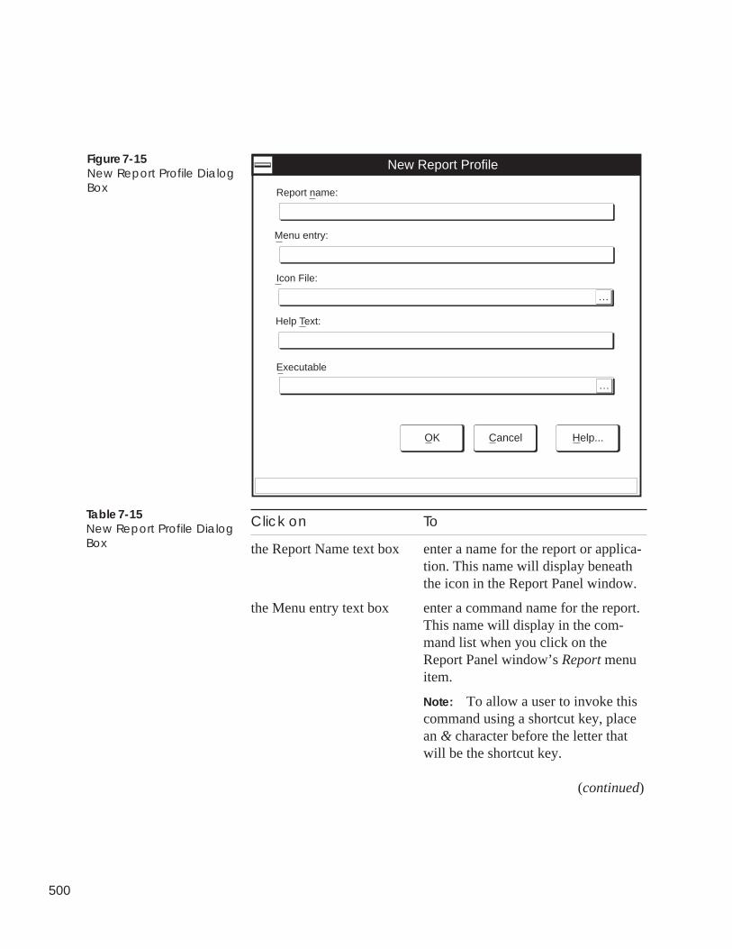
500
Figure 7-15New Report Profile DialogBox
New Report Profile
Report name:
OK Cancel Help...
Menu entry:
Icon File:
...
Help Text:
Executable
...
Click on To
the Report Name text box enter a name for the report or applica-tion. This name will display beneaththe icon in the Report Panel window.
the Menu entry text box enter a command name for the report.This name will display in the com-mand list when you click on theReport Panel window’s Report menuitem.
Note: To allow a user to invoke thiscommand using a shortcut key, placean & character before the letter thatwill be the shortcut key.
(continued)
Table 7-15New Report Profile DialogBox
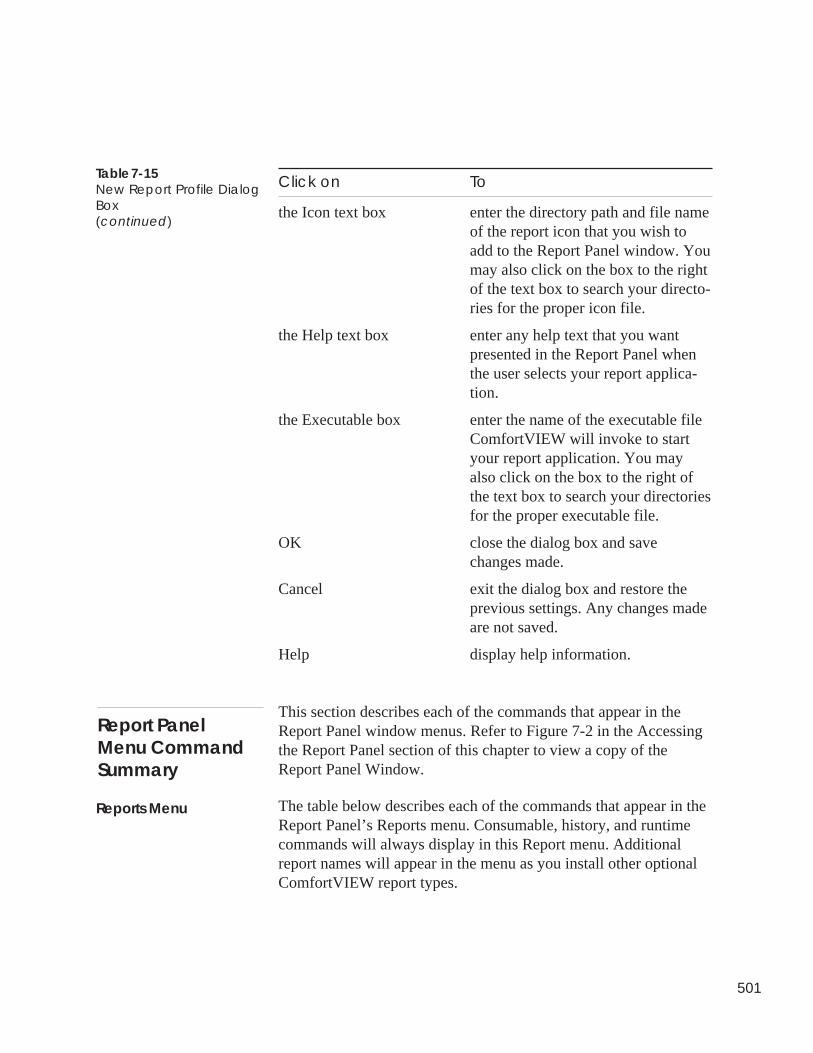
501
Click on To
the Icon text box enter the directory path and file nameof the report icon that you wish toadd to the Report Panel window. Youmay also click on the box to the rightof the text box to search your directo-ries for the proper icon file.
the Help text box enter any help text that you wantpresented in the Report Panel whenthe user selects your report applica-tion.
the Executable box enter the name of the executable fileComfortVIEW will invoke to startyour report application. You mayalso click on the box to the right ofthe text box to search your directoriesfor the proper executable file.
OK close the dialog box and savechanges made.
Cancel exit the dialog box and restore theprevious settings. Any changes madeare not saved.
Help display help information.
This section describes each of the commands that appear in theReport Panel window menus. Refer to Figure 7-2 in the Accessingthe Report Panel section of this chapter to view a copy of theReport Panel Window.
The table below describes each of the commands that appear in theReport Panel’s Reports menu. Consumable, history, and runtimecommands will always display in this Report menu. Additionalreport names will appear in the menu as you install other optionalComfortVIEW report types.
Table 7-15New Report Profile DialogBox(continued)
Report PanelMenu CommandSummary
Reports Menu
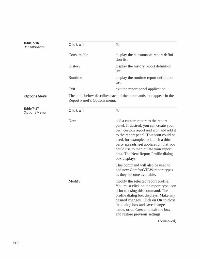
502
Click on To
Consumable display the consumable report defini-tion list.
History display the history report definitionlist.
Runtime display the runtime report definitionlist.
Exit exit the report panel application.
The table below describes each of the commands that appear in theReport Panel’s Options menu.
Click on To
New add a custom report to the reportpanel. If desired, you can create yourown custom report and icon and add itto the report panel. This icon could beused, for example, to launch a thirdparty spreadsheet application that youcould use to manipulate your reportdata. The New Report Profile dialogbox displays.
This command will also be used toadd new ComfortVIEW report typesas they become available.
Modify modify the selected report profile.You must click on the report type iconprior to using this command. Theprofile dialog box displays. Make anydesired changes. Click on OK to closethe dialog box and save changesmade, or on Cancel to exit the boxand restore previous settings.
(continued)
Table 7-16Reports Menu
Options Menu
Table 7-17Options Menu
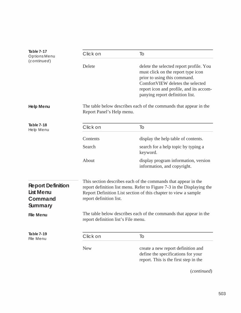
503
Click on To
Delete delete the selected report profile. Youmust click on the report type iconprior to using this command.ComfortVIEW deletes the selectedreport icon and profile, and its accom-panying report definition list.
The table below describes each of the commands that appear in theReport Panel’s Help menu.
Click on To
Contents display the help table of contents.
Search search for a help topic by typing akeyword.
About display program information, versioninformation, and copyright.
This section describes each of the commands that appear in thereport definition list menu. Refer to Figure 7-3 in the Displaying theReport Definition List section of this chapter to view a samplereport definition list.
The table below describes each of the commands that appear in thereport definition list’s File menu.
Click on To
New create a new report definition anddefine the specifications for yourreport. This is the first step in the
(continued)
Table 7-17Options Menu(continued)
Help Menu
Table 7-18Help Menu
Report DefinitionList MenuCommandSummary
File Menu
Table 7-19File Menu
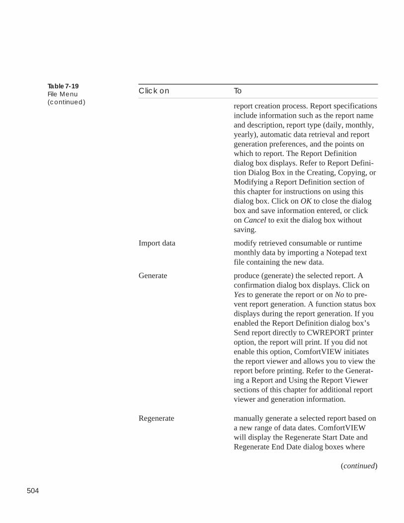
504
Click on To
report creation process. Report specificationsinclude information such as the report nameand description, report type (daily, monthly,yearly), automatic data retrieval and reportgeneration preferences, and the points onwhich to report. The Report Definitiondialog box displays. Refer to Report Defini-tion Dialog Box in the Creating, Copying, orModifying a Report Definition section ofthis chapter for instructions on using thisdialog box. Click on OK to close the dialogbox and save information entered, or clickon Cancel to exit the dialog box withoutsaving.
Import data modify retrieved consumable or runtimemonthly data by importing a Notepad textfile containing the new data.
Generate produce (generate) the selected report. Aconfirmation dialog box displays. Click onYes to generate the report or on No to pre-vent report generation. A function status boxdisplays during the report generation. If youenabled the Report Definition dialog box’sSend report directly to CWREPORT printeroption, the report will print. If you did notenable this option, ComfortVIEW initiatesthe report viewer and allows you to view thereport before printing. Refer to the Generat-ing a Report and Using the Report Viewersections of this chapter for additional reportviewer and generation information.
Regenerate manually generate a selected report based ona new range of data dates. ComfortVIEWwill display the Regenerate Start Date andRegenerate End Date dialog boxes where
(continued)
Table 7-19File Menu(continued)
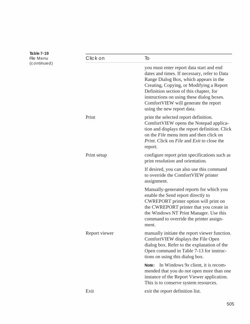
505
Click on To
you must enter report data start and enddates and times. If necessary, refer to DataRange Dialog Box, which appears in theCreating, Copying, or Modifying a ReportDefinition section of this chapter, forinstructions on using these dialog boxes.ComfortVIEW will generate the reportusing the new report data.
Print print the selected report definition.ComfortVIEW opens the Notepad applica-tion and displays the report definition. Clickon the File menu item and then click onPrint. Click on File and Exit to close thereport.
Print setup configure report print specifications such asprint resolution and orientation.
If desired, you can also use this commandto override the ComfortVIEW printerassignment.
Manually-generated reports for which youenable the Send report directly toCWREPORT printer option will print onthe CWREPORT printer that you create inthe Windows NT Print Manager. Use thiscommand to override the printer assign-ment.
Report viewer manually initiate the report viewer function.ComfortVIEW displays the File Opendialog box. Refer to the explanation of theOpen command in Table 7-13 for instruc-tions on using this dialog box.
Note: In Windows 9x client, it is recom-mended that you do not open more than oneinstance of the Report Viewer application.This is to conserve system resources.
Exit exit the report definition list.
Table 7-19File Menu(continued)
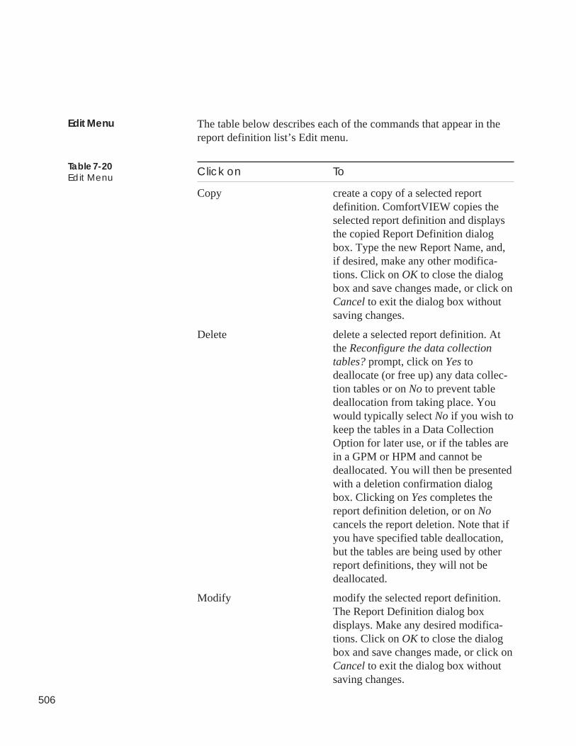
506
The table below describes each of the commands that appear in thereport definition list’s Edit menu.
Click on To
Copy create a copy of a selected reportdefinition. ComfortVIEW copies theselected report definition and displaysthe copied Report Definition dialogbox. Type the new Report Name, and,if desired, make any other modifica-tions. Click on OK to close the dialogbox and save changes made, or click onCancel to exit the dialog box withoutsaving changes.
Delete delete a selected report definition. Atthe Reconfigure the data collectiontables? prompt, click on Yes todeallocate (or free up) any data collec-tion tables or on No to prevent tabledeallocation from taking place. Youwould typically select No if you wish tokeep the tables in a Data CollectionOption for later use, or if the tables arein a GPM or HPM and cannot bedeallocated. You will then be presentedwith a deletion confirmation dialogbox. Clicking on Yes completes thereport definition deletion, or on Nocancels the report deletion. Note that ifyou have specified table deallocation,but the tables are being used by otherreport definitions, they will not bedeallocated.
Modify modify the selected report definition.The Report Definition dialog boxdisplays. Make any desired modifica-tions. Click on OK to close the dialogbox and save changes made, or click onCancel to exit the dialog box withoutsaving changes.
Edit Menu
Table 7-20Edit Menu
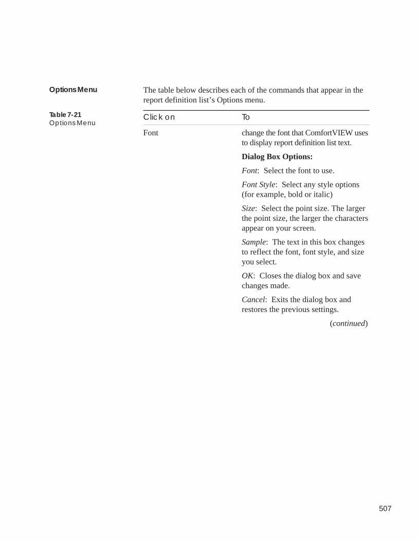
507
The table below describes each of the commands that appear in thereport definition list’s Options menu.
Click on To
Font change the font that ComfortVIEW usesto display report definition list text.
Dialog Box Options:
Font: Select the font to use.
Font Style: Select any style options(for example, bold or italic)
Size: Select the point size. The largerthe point size, the larger the charactersappear on your screen.
Sample: The text in this box changesto reflect the font, font style, and sizeyou select.
OK: Closes the dialog box and savechanges made.
Cancel: Exits the dialog box andrestores the previous settings.
(continued)
Options Menu
Table 7-21Options Menu
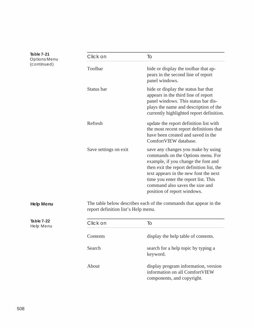
508
Click on To
Toolbar hide or display the toolbar that ap-pears in the second line of reportpanel windows.
Status bar hide or display the status bar thatappears in the third line of reportpanel windows. This status bar dis-plays the name and description of thecurrently highlighted report definition.
Refresh update the report definition list withthe most recent report definitions thathave been created and saved in theComfortVIEW database.
Save settings on exit save any changes you make by usingcommands on the Options menu. Forexample, if you change the font andthen exit the report definition list, thetext appears in the new font the nexttime you enter the report list. Thiscommand also saves the size andposition of report windows.
The table below describes each of the commands that appear in thereport definition list’s Help menu.
Click on To
Contents display the help table of contents.
Search search for a help topic by typing akeyword.
About display program information, versioninformation on all ComfortVIEWcomponents, and copyright.
Table 7-21Options Menu(continued)
Help Menu
Table 7-22Help Menu
509
This section contains sample ComfortVIEW reports.
The following reports are included:
• Consumable Daily Report• Consumable Monthly Report• Consumable Yearly Report
• Runtime Daily Report• Runtime Monthly Report• Runtime Yearly Report
• History Report
Sample reports for additional ComfortVIEW reports can be found inAppendix A.
Sample Reports
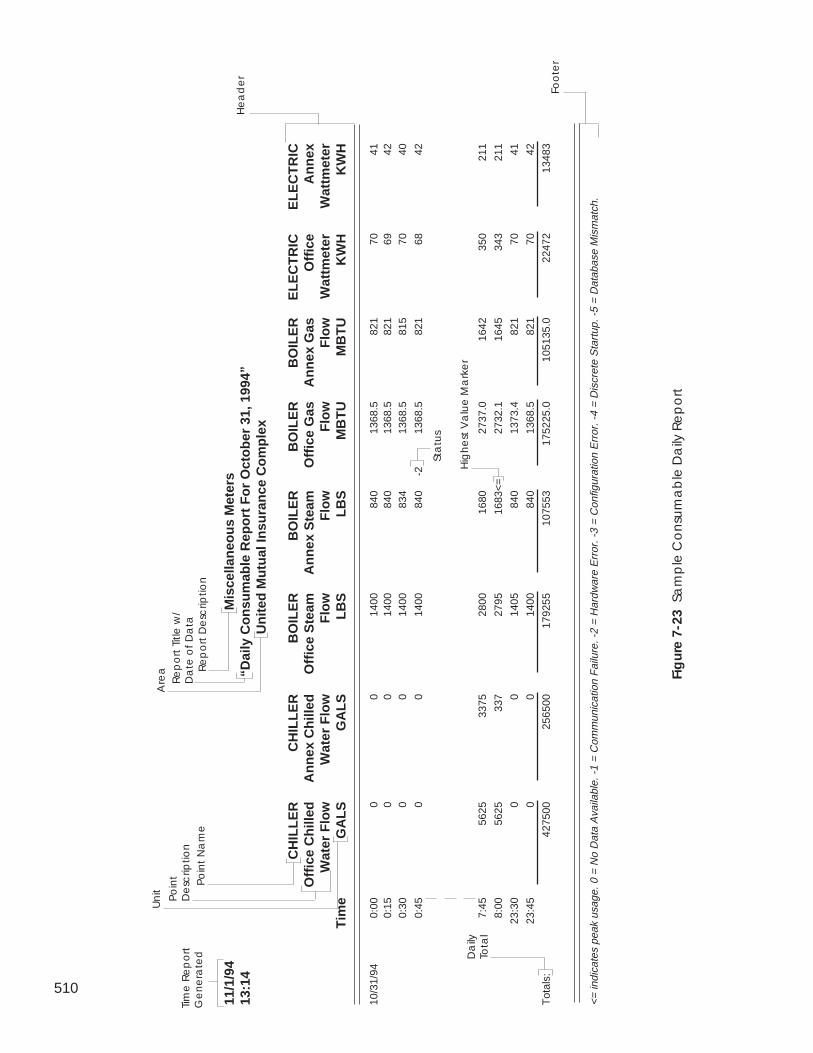
510
11/1
/94
Mis
cella
neo
us
Met
ers
13:1
4“D
aily
Co
nsu
mab
le R
epo
rt F
or
Oct
ob
er 3
1, 1
994”
Un
ited
Mu
tual
Insu
ran
ce C
om
ple
x
CH
ILL
ER
CH
ILL
ER
BO
ILE
RB
OIL
ER
BO
ILE
RB
OIL
ER
EL
EC
TR
ICE
LE
CT
RIC
Off
ice
Ch
illed
An
nex
Ch
illed
Off
ice
Ste
amA
nn
ex S
team
Off
ice
Gas
An
nex
Gas
Off
ice
An
nex
Wat
er F
low
Wat
er F
low
Flo
wF
low
Flo
wF
low
Wat
tmet
erW
attm
eter
Tim
eG
AL
SG
AL
SL
BS
LB
SM
BT
UM
BT
UK
WH
KW
H
10/3
1/94
0:00
00
1400
840
1368
.582
170
410:
150
014
0084
013
68.5
821
6942
0:30
00
1400
834
1368
.581
570
40
0:45
00
1400
840
-213
68.5
821
6842
7:45
5625
3375
2800
1680
2737
.016
4235
021
1
8:00
5625
337
2795
1683
<=
2732
.116
4534
321
1
23:3
00
014
0584
013
73.4
821
7041
23:4
50
014
0084
013
68.5
821
7042
Tot
als:
4275
0025
6500
1792
5510
7553
1752
25.0
1051
35.0
2247
213
483
<= in
dica
tes
peak
usa
ge. 0
= N
o D
ata
Ava
ilabl
e. -
1 =
Com
mun
icat
ion
Fai
lure
. -2
= H
ardw
are
Err
or. -
3 =
Con
figur
atio
n E
rror
. -4
= D
iscr
ete
Sta
rtup
. -5
= D
atab
ase
Mis
mat
ch.
Foo
ter
Re
po
rt T
itle
w/
Da
te o
f D
ata
He
ad
er
Fig
ure
7-2
3 S
am
ple
Co
nsu
ma
ble
Da
ily R
ep
ort
Are
a Re
po
rt D
esc
riptio
n
Un
it
Po
int
Na
me
Da
ilyTo
tal
Tim
e R
ep
ort
Ge
ne
rate
d
Po
int
De
scrip
tion
Hig
he
st V
alu
e M
ark
er
Sta
tus
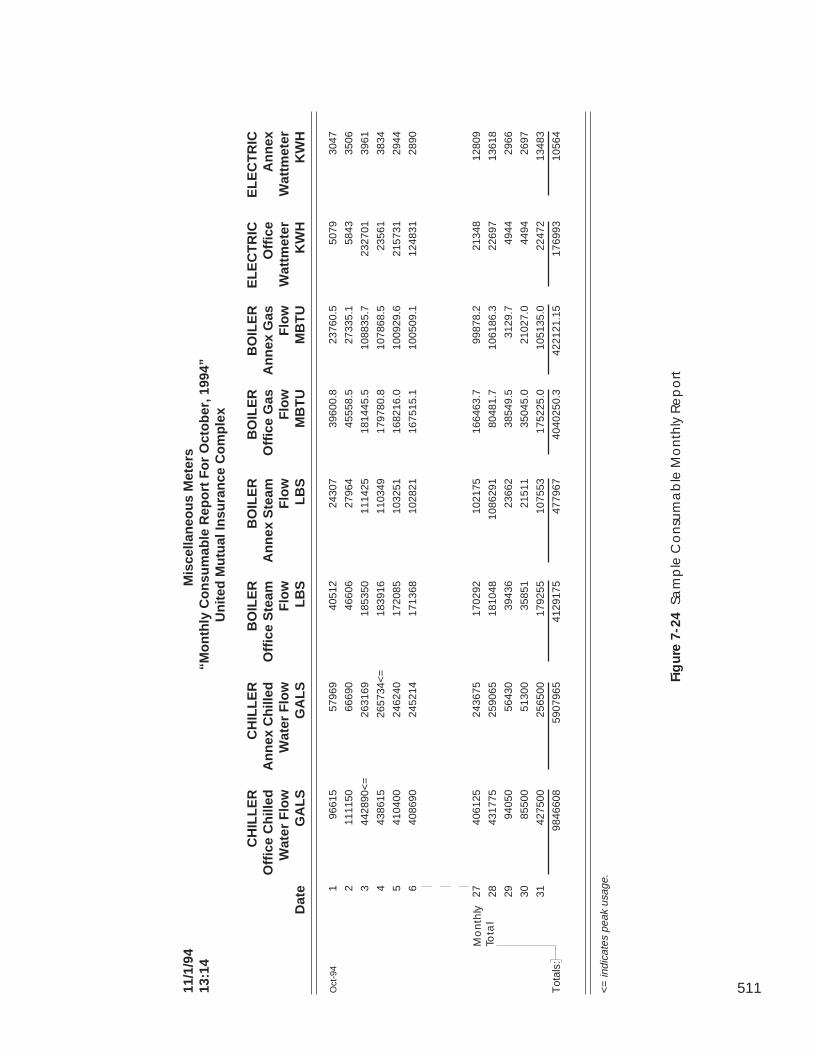
511
Fig
ure
7-2
4 Sa
mp
le C
on
sum
ab
le M
on
thly
Re
po
rt
Mo
nth
lyTo
tal
11/1
/94
Mis
cella
neo
us
Met
ers
13:1
4“M
on
thly
Co
nsu
mab
le R
epo
rt F
or
Oct
ob
er, 1
994”
Un
ited
Mu
tual
Insu
ran
ce C
om
ple
x
CH
ILL
ER
CH
ILL
ER
BO
ILE
RB
OIL
ER
BO
ILE
RB
OIL
ER
EL
EC
TR
ICE
LE
CT
RIC
Off
ice
Ch
illed
An
nex
Ch
illed
Off
ice
Ste
amA
nn
ex S
team
Off
ice
Gas
An
nex
Gas
Off
ice
An
nex
Wat
er F
low
Wat
er F
low
Flo
wF
low
Flo
wF
low
Wat
tmet
erW
attm
eter
Dat
eG
AL
SG
AL
SL
BS
LB
SM
BT
UM
BT
UK
WH
KW
H
Oct
-94
196
615
5796
940
512
2430
739
600.
823
760.
550
7930
47
211
1150
6669
046
606
2796
445
558.
527
335.
158
4335
06
344
2890
<=
2631
6918
5350
1114
2518
1445
.510
8835
.723
2701
3961
443
8615
2657
34<
=18
3916
1103
4917
9780
.810
7868
.523
561
3834
541
0400
2462
4017
2085
1032
5116
8216
.010
0929
.621
5731
2944
640
8690
2452
1417
1368
1028
2116
7515
.110
0509
.112
4831
2890
2740
6125
2436
7517
0292
1021
7516
6463
.799
878.
221
348
1280
9
2843
1775
2590
6518
1048
1086
291
8048
1.7
1061
86.3
2269
713
618
2994
050
5643
039
436
2366
238
549.
531
29.7
4944
2966
3085
500
5130
035
851
2151
135
045.
021
027.
044
9426
97
3142
7500
2565
0017
9255
1075
5317
5225
.010
5135
.022
472
1348
3
Tot
als:
9846
608
5907
965
4129
175
4779
6740
4025
0.3
4221
21.1
517
6993
1056
4
<=
indi
cate
s pe
ak u
sage
.
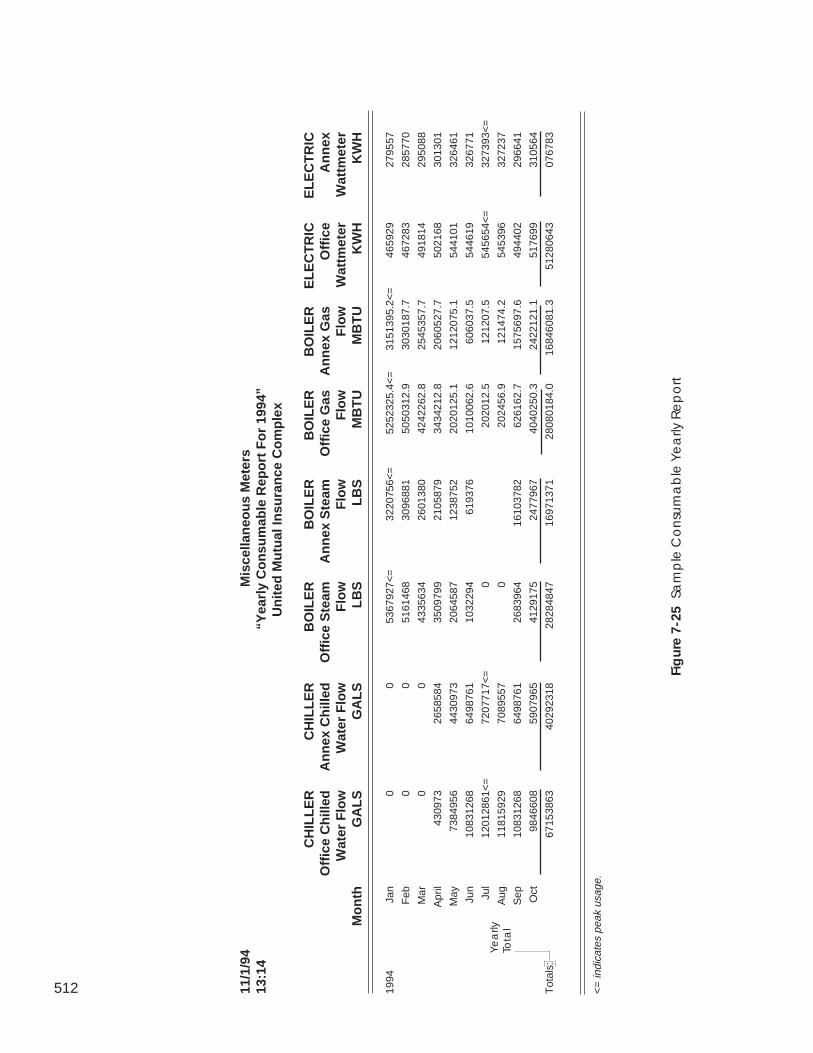
512 11/1
/94
Mis
cella
neo
us
Met
ers
13:1
4“Y
earl
y C
on
sum
able
Rep
ort
Fo
r 19
94”
Un
ited
Mu
tual
Insu
ran
ce C
om
ple
x
CH
ILL
ER
CH
ILL
ER
BO
ILE
RB
OIL
ER
BO
ILE
RB
OIL
ER
EL
EC
TR
ICE
LE
CT
RIC
Off
ice
Ch
illed
An
nex
Ch
illed
Off
ice
Ste
amA
nn
ex S
team
Off
ice
Gas
An
nex
Gas
Off
ice
An
nex
Wat
er F
low
Wat
er F
low
Flo
wF
low
Flo
wF
low
Wat
tmet
erW
attm
eter
Mo
nth
GA
LS
GA
LS
LB
SL
BS
MB
TU
MB
TU
KW
HK
WH
1994
Jan
00
5367
927<
=32
2075
6<=
5252
325.
4<=
3151
395.
2<=
4659
2927
9557
Feb
00
5161
468
3096
881
5050
312.
930
3018
7.7
4672
8328
5770
Mar
00
4335
634
2601
380
4242
262.
825
4535
7.7
4918
1429
5088
Apr
il43
0973
2658
584
3509
799
2105
879
3434
212.
820
6052
7.7
5021
6830
1301
May
7384
956
4430
973
2064
587
1238
752
2020
125.
112
1207
5.1
5441
0132
6461
Jun
1083
1268
6498
761
1032
294
6193
7610
1006
2.6
6060
37.5
5446
1932
6771
Jul
1201
2861
<=
7207
717<
=0
2020
12.5
1212
07.5
5456
54<
=32
7393
<=
Aug
1181
5929
7089
557
020
2456
.912
1474
.254
5396
3272
37
Sep
1083
1268
6498
761
2683
964
1610
3782
6261
62.7
1575
697.
649
4402
2966
41
Oct
9846
608
5907
965
4129
175
2477
967
4040
250.
324
2212
1.1
5176
9931
0564
Tot
als:
6715
3863
4029
2318
2828
4847
1697
1371
2808
0184
.016
8460
81.3
5128
0643
0767
83
<=
indi
cate
s pe
ak u
sage
.
Fig
ure
7-2
5 Sa
mp
le C
on
sum
ab
le Y
ea
rly R
ep
ort
Ye
arly
Tota
l
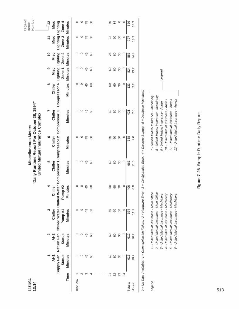
51311/1
/94
Mis
cella
neo
us
Met
ers
13:1
4“D
aily
Ru
nti
me
Rep
ort
Fo
r O
cto
ber
28,
199
4”U
nit
ed M
utu
al In
sura
nce
Co
mp
lex
12
34
56
78
910
1112
AH
1A
H2
Ch
iller
Ch
iller
Ch
iller
Ch
iller
Ch
iller
Ch
iller
Mis
cM
isc
Mis
cM
isc
Su
pp
ly F
anR
etu
rn F
anC
hill
ed W
ater
Ch
illed
Wat
erC
om
pre
sso
r 1
Co
mp
ress
or
2C
om
pre
sso
r 3
Co
mp
ress
or
4L
igh
tin
gL
igh
tin
gL
igh
tin
gL
igh
tin
gS
tatu
sS
tatu
sP
um
p #
1P
um
p #
2Z
on
e 1
Zo
ne
2Z
on
e 3
Zo
ne
4T
ime
Min
ute
sM
inu
tes
Min
ute
sM
inu
tes
Min
ute
sM
inu
tes
Min
ute
sM
inu
tes
Min
ute
sM
inu
tes
Min
ute
sM
inu
tes
10/2
8/94
10
00
00
00
00
00
0
20
00
00
00
00
00
0
345
4545
4545
4545
4545
4545
45
460
6060
6060
6060
6060
6060
60
2160
6060
6060
6060
6060
2622
60
2260
6060
6060
6060
6060
6020
34
2330
3030
3030
3030
3030
3030
0
240
00
00
00
00
00
0
Tot
als:
613
612
664
406
661
538
421
133
824
885
797
856
Hou
rs:
10.2
10.2
11.1
6.8
11.0
9.0
7.0
2.2
13.7
14.8
13.3
14.3
0 =
No
Dat
a A
vaila
ble.
-1
= C
omm
unic
atio
n F
ailu
re. -
2 =
Har
dwar
e E
rror
. -3
= C
onfig
urat
ion
Err
or. -
4 =
Dis
cret
e S
tart
up. -
5 =
Dat
abas
e M
ism
atch
.
Lege
nd1
- U
nite
d M
utua
l Ins
uran
ce -
Mai
n O
ffice
7 -
Uni
ted
Mut
ual I
nsur
ance
- M
achi
nery
2 -
Uni
ted
Mut
ual I
nsur
ance
- M
ain
Offi
ce8
- U
nite
d M
utua
l Ins
uran
ce -
Mac
hine
ry
3 -
Uni
ted
Mut
ual I
nsur
ance
- M
achi
nery
9 -
Uni
ted
Mut
ual I
nsur
ance
- A
nnex
4 -
Uni
ted
Mut
ual I
nsur
ance
- M
achi
nery
10 -
Uni
ted
Mut
ual I
nsur
ance
- A
nnex
5 -
Uni
ted
Mut
ual I
nsur
ance
- M
achi
nery
11 -
Uni
ted
Mut
ual I
nsur
ance
- A
nnex
6 -
Uni
ted
Mut
ual I
nsur
ance
- M
achi
nery
12 -
Uni
ted
Mut
ual I
nsur
ance
- A
nnex
Fig
ure
7-2
6 S
am
ple
Ru
ntim
e D
aily
Re
po
rt
Leg
en
d
Leg
en
dIn
de
xN
um
be
r
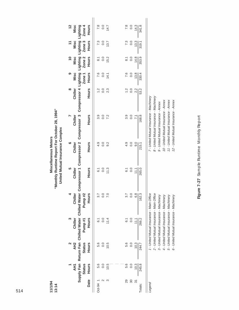
514 11/1
/94
Mis
cella
neo
us
Met
ers
13:1
4“M
on
thly
Ru
nti
me
Rep
ort
Fo
r O
cto
ber
28,
199
4”U
nit
ed M
utu
al In
sura
nce
Co
mp
lex
12
34
56
78
910
1112
AH
1A
H2
Ch
iller
Ch
iller
Ch
iller
Ch
iller
Ch
iller
Ch
iller
Mis
cM
isc
Mis
cM
isc
Su
pp
ly F
anR
etu
rn F
anC
hill
ed W
ater
Ch
illed
Wat
erC
om
pre
sso
r 1
Co
mp
ress
or
2C
om
pre
sso
r 3
Co
mp
ress
or
4L
igh
tin
gL
igh
tin
gL
igh
tin
gL
igh
tin
gS
tatu
sS
tatu
sP
um
p #
1P
um
p #
2Z
on
e 1
Zo
ne
2Z
on
e 3
Zo
ne
4D
ate
Ho
urs
Ho
urs
Ho
urs
Ho
urs
Ho
urs
Ho
urs
Ho
urs
Ho
urs
Ho
urs
Ho
urs
Ho
urs
Ho
urs
Oct
-94
15.
65.
66.
13.
76.
14.
93.
91.
27.
68.
17.
37.
8
20.
00.
00.
00.
00.
00.
00.
00.
00.
00.
00.
00.
0
310
.510
.511
.47.
011
.39.
27.
22.
314
.115
.213
.714
.7
295.
65.
66.
13.
76.
14.
93.
91.
27.
68.
17.
37.
8
300.
00.
00.
00.
00.
00.
00.
00.
00.
00.
00.
00.
0
3110
.310
.311
.16.
811
.19.
07.
12.
213
.814
.813
.314
.3
Tot
als:
245.
824
4.7
266.
216
2.3
265.
021
5.1
168.
853
.233
0.4
353.
931
9.1
341.
8
Lege
nd1
- U
nite
d M
utua
l Ins
uran
ce -
Mai
n O
ffice
7 -
Uni
ted
Mut
ual I
nsur
ance
- M
achi
nery
2 -
Uni
ted
Mut
ual I
nsur
ance
- M
ain
Offi
ce8
- U
nite
d M
utua
l Ins
uran
ce -
Mac
hine
ry
3 -
Uni
ted
Mut
ual I
nsur
ance
- M
achi
nery
9 -
Uni
ted
Mut
ual I
nsur
ance
- A
nnex
4 -
Uni
ted
Mut
ual I
nsur
ance
- M
achi
nery
10 -
Uni
ted
Mut
ual I
nsur
ance
- A
nnex
5 -
Uni
ted
Mut
ual I
nsur
ance
- M
achi
nery
11 -
Uni
ted
Mut
ual I
nsur
ance
- A
nnex
6 -
Uni
ted
Mut
ual I
nsur
ance
- M
achi
nery
12 -
Uni
ted
Mut
ual I
nsur
ance
- A
nnex
Fig
ure
7-2
7 S
am
ple
Ru
ntim
e M
on
thly
Re
po
rt
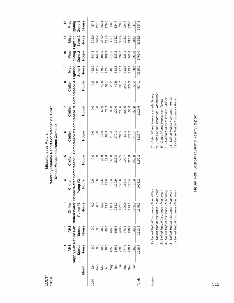
515
Fig
ure
7-2
8 S
am
ple
Ru
ntim
e Y
ea
rly R
ep
ort
11/1
/94
Mis
cella
neo
us
Met
ers
13:1
4“M
on
thly
Ru
nti
me
Rep
ort
Fo
r O
cto
ber
28,
199
4”U
nit
ed M
utu
al In
sura
nce
Co
mp
lex
12
34
56
78
910
1112
AH
1A
H2
Ch
iller
Ch
iller
Ch
iller
Ch
iller
Ch
iller
Ch
iller
Mis
cM
isc
Mis
cM
isc
Su
pp
ly F
anR
etu
rn F
anC
hill
ed W
ater
Ch
illed
Wat
erC
om
pre
sso
r 1
Co
mp
ress
or
2C
om
pre
sso
r 3
Co
mp
ress
or
4L
igh
tin
gL
igh
tin
gL
igh
tin
gL
igh
tin
gS
tatu
sS
tatu
sP
um
p #
1P
um
p #
2Z
on
e 1
Zo
ne
2Z
on
e 3
Zo
ne
4M
on
thH
ou
rsH
ou
rsH
ou
rsH
ou
rsH
ou
rsH
ou
rsH
ou
rsH
ou
rsH
ou
rsH
ou
rsH
ou
rsH
ou
rs
1994
Jan
0.0
0.0
0.0
0.0
0.0
0.0
0.0
0.0
412.
944
2.3
398.
942
7.3
Feb
0.0
0.0
0.0
0.0
0.0
0.0
0.0
0.0
412.
944
2.3
398.
942
7.3
Mar
49.2
48.9
53.2
32.5
33.8
10.6
53.0
43.0
379.
940
6.9
367.
039
3.1
Apr
86.0
85.6
93.2
56.8
18.6
92.8
75.3
59.1
363.
438
9.2
351.
037
6.0
May
135.
213
4.6
146.
489
.314
5.8
118.
392
.829
.234
6.9
371.
533
5.1
358.
9
Jun
196.
619
5.8
213.
012
9.9
212.
017
2.1
135.
042
.531
3.8
336.
230
3.2
324.
7
Jul
270.
326
9.2
292.
817
8.6
58.5
291.
523
6.6
185.
731
7.1
339.
730
6.4
328.
2
Aug
277.
727
6.5
300.
818
3.4
190.
760
.129
9.5
243.
131
3.8
336.
230
3.2
324.
7
Sep
258.
125
6.9
279.
517
0.4
225.
917
7.2
55.8
278.
332
3.7
346.
831
2.7
335.
0
Oct
245.
824
4.7
266.
216
2.3
265.
021
5.1
168.
853
.233
0.4
353.
931
9.1
341.
8
Tot
als:
1518
.815
12.2
1645
.210
03.2
1150
.211
37.7
1116
.993
4.1
3515
.037
65.0
3395
.636
37.1
Lege
nd1
- U
nite
d M
utua
l Ins
uran
ce -
Mai
n O
ffice
7 -
Uni
ted
Mut
ual I
nsur
ance
- M
achi
nery
2 -
Uni
ted
Mut
ual I
nsur
ance
- M
ain
Offi
ce8
- U
nite
d M
utua
l Ins
uran
ce -
Mac
hine
ry
3 -
Uni
ted
Mut
ual I
nsur
ance
- M
achi
nery
9 -
Uni
ted
Mut
ual I
nsur
ance
- A
nnex
4 -
Uni
ted
Mut
ual I
nsur
ance
- M
achi
nery
10 -
Uni
ted
Mut
ual I
nsur
ance
- A
nnex
5 -
Uni
ted
Mut
ual I
nsur
ance
- M
achi
nery
11 -
Uni
ted
Mut
ual I
nsur
ance
- A
nnex
6 -
Uni
ted
Mut
ual I
nsur
ance
- M
achi
nery
12 -
Uni
ted
Mut
ual I
nsur
ance
- A
nnex
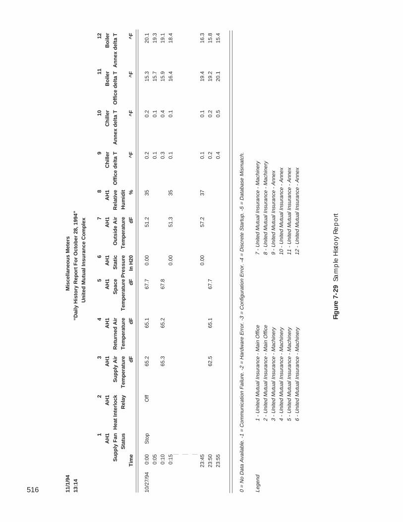
516 11/1
/94
Mis
cella
neo
us
Met
ers
13:1
4“D
aily
His
tory
Rep
ort
Fo
r O
cto
ber
28,
199
4”
Un
ited
Mu
tual
Insu
ran
ce C
om
ple
x
12
34
56
78
910
1112
AH
1A
H1
AH
1A
H1
AH
1A
H1
AH
1A
H1
Ch
iller
Ch
iller
Bo
iler
Bo
iler
Su
pp
ly F
anH
eat
Inte
rlo
ckS
up
ply
Air
Ret
urn
ed A
irS
pac
eS
tati
cO
uts
ide
Air
Rel
ativ
eO
ffic
e d
elta
TA
nn
ex d
elta
TO
ffic
e d
elta
TA
nn
ex d
elta
T
Sta
tus
Rel
ayT
emp
erat
ure
Tem
per
atu
reT
emp
erat
ure
Pre
ssu
reT
emp
erat
ure
Hu
mid
it
Tim
ed
Fd
Fd
FIn
H20
dF
%^F
^F^F
^F
10/2
7/94
0:00
Sto
pO
ff65
.265
.167
.70.
0051
.235
0.2
0.2
15.3
20.1
0:05
0.1
0.1
15.7
19.3
0:10
65.3
65.2
67.8
0.3
0.4
15.9
19.1
0:15
0.00
51.3
350.
10.
116
.418
.4
23:4
50.
0057
.237
0.1
0.1
19.4
16.3
23:5
062
.565
.167
.70.
20.
219
.215
.8
23:5
50.
40.
520
.115
.4
0 =
No
Dat
a A
vaila
ble.
-1
= C
omm
unic
atio
n F
ailu
re. -
2 =
Har
dwar
e E
rror
. -3
= C
onfig
urat
ion
Err
or. -
4 =
Dis
cret
e S
tart
up. -
5 =
Dat
abas
e M
ism
atch
.
Lege
nd1
- U
nite
d M
utua
l Ins
uran
ce -
Mai
n O
ffice
7 -
Uni
ted
Mut
ual I
nsur
ance
- M
achi
nery
2 -
Uni
ted
Mut
ual I
nsur
ance
- M
ain
Offi
ce8
- U
nite
d M
utua
l Ins
uran
ce -
Mac
hine
ry
3 -
Uni
ted
Mut
ual I
nsur
ance
- M
achi
nery
9 -
Uni
ted
Mut
ual I
nsur
ance
- A
nnex
4 -
Uni
ted
Mut
ual I
nsur
ance
- M
achi
nery
10 -
Uni
ted
Mut
ual I
nsur
ance
- A
nnex
5 -
Uni
ted
Mut
ual I
nsur
ance
- M
achi
nery
11 -
Uni
ted
Mut
ual I
nsur
ance
- A
nnex
6 -
Uni
ted
Mut
ual I
nsur
ance
- M
achi
nery
12 -
Uni
ted
Mut
ual I
nsur
ance
- A
nnex
Fig
ure
7-2
9 S
am
ple
Hist
ory
Re
po
rt

Global FunctionManager

Alarm Manager
517
This chapter provides information on ComfortVIEW's Global Func-tion Manager application.
For instructions on... Turn to page
launching the Global Function Manager application 517
configuring a ComfortVIEW server to automaticallyforce and auto user-specified groups of points 517
transmitting data from point to point or broadcastingpoint data onto the CCN Bus 522
creating global occupancy schedules 527
configuring global holidays 527
a summary of all Global Function Manager commands 534
To launch the Global Function Manager application:
Double click on the Global Function Manager icon.
ComfortVIEW displays the Global Function Manager window. Thetop line of the window contains the Global Function Manager menu.Refer to Global Function Manager Menu Command Summary at theend of this chapter for a description of each menu item and com-mand.
You can configure a ComfortVIEW server to automatically forceand auto one or more user-specified points, based on user-specifiedtime parameters.
Follow the steps below to set up, modify, or delete a timed force:
1. Click on the Functions menu item and then click on TimedForce.
The Timed Force Groups dialog box is displayed. Refer toFigure and Table 8-1. This dialog box contains the names ofall currently-configured force groups. As you select a forcegroup, the group's force and auto time, force precedence,enable/disable status, and the names of all points that arecurrently assigned to the group display under Force group
GlobalFunctionManager
Timed Force
Launching theGlobal
FunctionManagerApplication
518
information and in the Force points: list in the lower sectionof the dialog box.
2. In the Timed Force Groups dialog box, you can do the fol-lowing:
• Click on New to define a new force group (up to 300force groups can exist), or click on an existing forcegroup and then click on Modify to modify it. The TimedForce Points dialog box will be displayed. Use this dialogbox to add and delete points from the group (up to 60points per group), and to specify force precedence, andforce and auto time. Double click on the Value cell tospecify a new or modify the existing force value. Refer toFigure and Table 8-2 for instructions on using this dialogbox.
• Click on an existing force group, and then click on Deleteto delete it. In the confirmation dialog box, click on Yesto delete the group or on No to close the dialog boxwithout group deletion.
3. Click on OK to close the Timed Force Groups dialog box andsave your settings or on Cancel to close the dialog boxwithout saving settings.
At the specified time, ComfortVIEW will force the points identifiedfor each group. Successes and failures will be logged in the SystemActivity log using an operator name of ComfortVIEW and an eventof either Timed force or Timed force with auto, depending onwhether an auto time was configured for the point, and whether thepoint being forced supports the force with auto feature. Alarms willbe generated for failures. Those points for which an auto time isconfigured that do not support the force with auto feature, willreceive a standard force and ComfortVIEW will issue the autocommand at the appropriate time. If the ComfortVIEW server isturned off before the scheduled auto time, the auto will not beperformed. ComfortVIEW will not perform forces or autos onpoints whose force or auto time occurred while ComfortVIEW wasnot running.
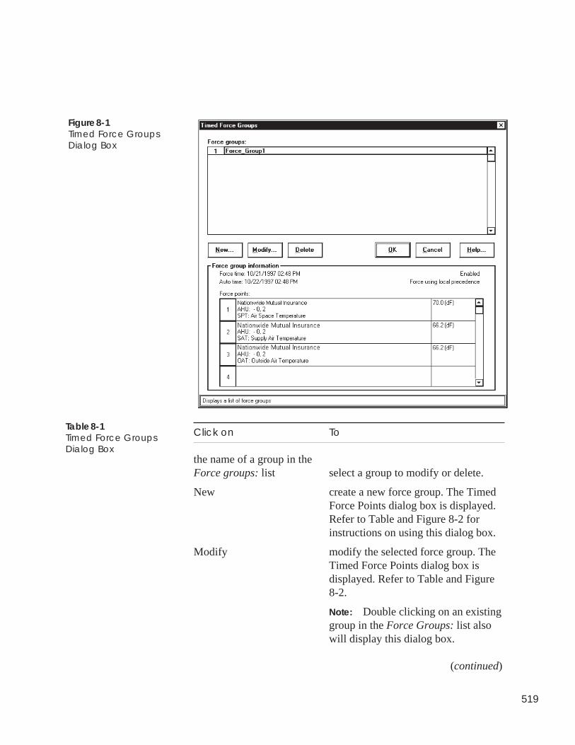
519
Figure 8-1Timed Force GroupsDialog Box
Click on To
the name of a group in theForce groups: list select a group to modify or delete.
New create a new force group. The TimedForce Points dialog box is displayed.Refer to Table and Figure 8-2 forinstructions on using this dialog box.
Modify modify the selected force group. TheTimed Force Points dialog box isdisplayed. Refer to Table and Figure8-2.
Note: Double clicking on an existinggroup in the Force Groups: list alsowill display this dialog box.
(continued)
Table 8-1Timed Force GroupsDialog Box
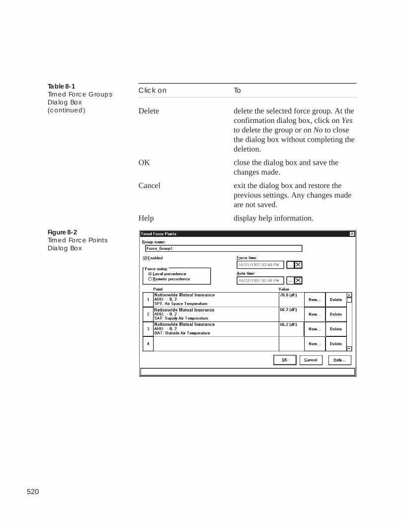
520
Click on To
Delete delete the selected force group. At theconfirmation dialog box, click on Yesto delete the group or on No to closethe dialog box without completing thedeletion.
OK close the dialog box and save thechanges made.
Cancel exit the dialog box and restore theprevious settings. Any changes madeare not saved.
Help display help information.
Table 8-1Timed Force GroupsDialog Box(continued)
Figure 8-2Timed Force PointsDialog Box
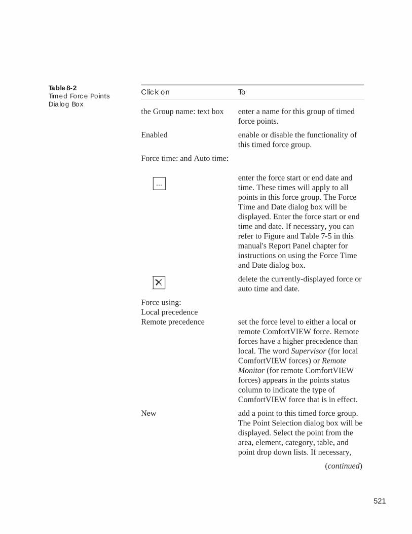
521
Click on To
the Group name: text box enter a name for this group of timedforce points.
Enabled enable or disable the functionality ofthis timed force group.
Force time: and Auto time:
enter the force start or end date andtime. These times will apply to allpoints in this force group. The ForceTime and Date dialog box will bedisplayed. Enter the force start or endtime and date. If necessary, you canrefer to Figure and Table 7-5 in thismanual's Report Panel chapter forinstructions on using the Force Timeand Date dialog box.
delete the currently-displayed force orauto time and date.
Force using:Local precedenceRemote precedence set the force level to either a local or
remote ComfortVIEW force. Remoteforces have a higher precedence thanlocal. The word Supervisor (for localComfortVIEW forces) or RemoteMonitor (for remote ComfortVIEWforces) appears in the points statuscolumn to indicate the type ofComfortVIEW force that is in effect.
New add a point to this timed force group.The Point Selection dialog box will bedisplayed. Select the point from thearea, element, category, table, andpoint drop down lists. If necessary,
(continued)
Table 8-2Timed Force PointsDialog Box
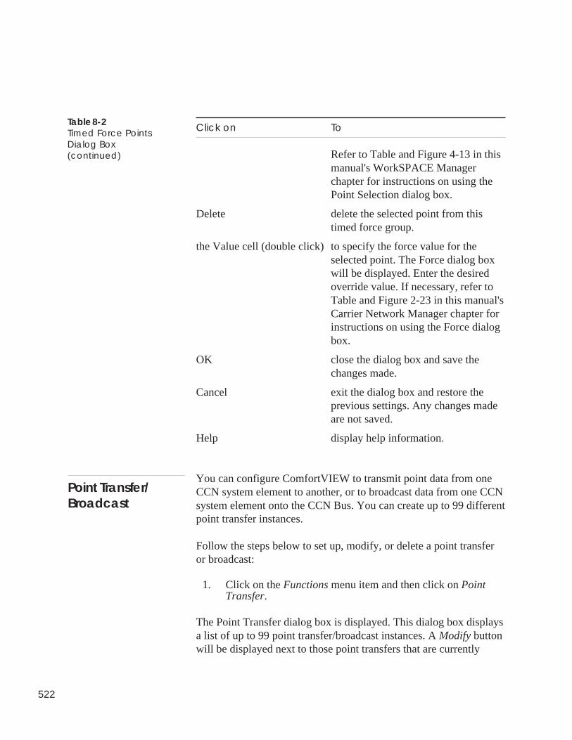
522
Click on To
Refer to Table and Figure 4-13 in thismanual's WorkSPACE Managerchapter for instructions on using thePoint Selection dialog box.
Delete delete the selected point from thistimed force group.
the Value cell (double click) to specify the force value for theselected point. The Force dialog boxwill be displayed. Enter the desiredoverride value. If necessary, refer toTable and Figure 2-23 in this manual'sCarrier Network Manager chapter forinstructions on using the Force dialogbox.
OK close the dialog box and save thechanges made.
Cancel exit the dialog box and restore theprevious settings. Any changes madeare not saved.
Help display help information.
You can configure ComfortVIEW to transmit point data from oneCCN system element to another, or to broadcast data from one CCNsystem element onto the CCN Bus. You can create up to 99 differentpoint transfer instances.
Follow the steps below to set up, modify, or delete a point transferor broadcast:
1. Click on the Functions menu item and then click on PointTransfer.
The Point Transfer dialog box is displayed. This dialog box displaysa list of up to 99 point transfer/broadcast instances. A Modify buttonwill be displayed next to those point transfers that are currently
Table 8-2Timed Force PointsDialog Box(continued)
Point Transfer/Broadcast
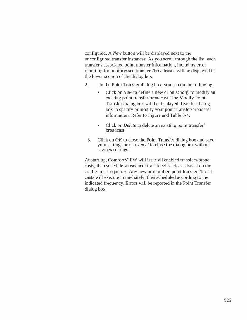
523
configured. A New button will be displayed next to theunconfigured transfer instances. As you scroll through the list, eachtransfer's associated point transfer information, including errorreporting for unprocessed transfers/broadcasts, will be displayed inthe lower section of the dialog box.
2. In the Point Transfer dialog box, you can do the following:
• Click on New to define a new or on Modify to modify anexisting point transfer/broadcast. The Modify PointTransfer dialog box will be displayed. Use this dialogbox to specify or modify your point transfer/broadcastinformation. Refer to Figure and Table 8-4.
• Click on Delete to delete an existing point transfer/broadcast.
3. Click on OK to close the Point Transfer dialog box and saveyour settings or on Cancel to close the dialog box withoutsavings settings.
At start-up, ComfortVIEW will issue all enabled transfers/broad-casts, then schedule subsequent transfers/broadcasts based on theconfigured frequency. Any new or modified point transfers/broad-casts will execute immediately, then scheduled according to theindicated frequency. Errors will be reported in the Point Transferdialog box.
524
Figure 8-3Point TransferDialog Box
Click on To
New configure a new point transfer orbroadcast instance. The Modify PointTransfer dialog box is displayed.Refer to Table and Figure 8-4 forinstructions on using this dialog box.
Modify modify a point transfer or broadcast.The Modify Point Transfer dialog boxis displayed. Refer to Table andFigure 8-4.
Note: Double clicking on any pointtransfer instance also will display thisdialog box.
OK close the dialog box and save thechanges made.
(continued)
Table 8-3Point TransferDialog Box
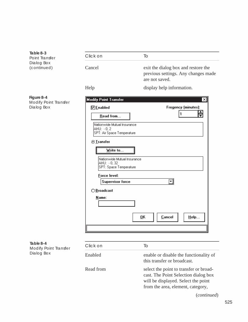
525
Click on To
Cancel exit the dialog box and restore theprevious settings. Any changes madeare not saved.
Help display help information.
Table 8-3Point TransferDialog Box(continued)
Figure 8-4Modify Point TransferDialog Box
Click on To
Enabled enable or disable the functionality ofthis transfer or broadcast.
Read from select the point to transfer or broad-cast. The Point Selection dialog boxwill be displayed. Select the pointfrom the area, element, category,
(continued)
Table 8-4Modify Point TransferDialog Box
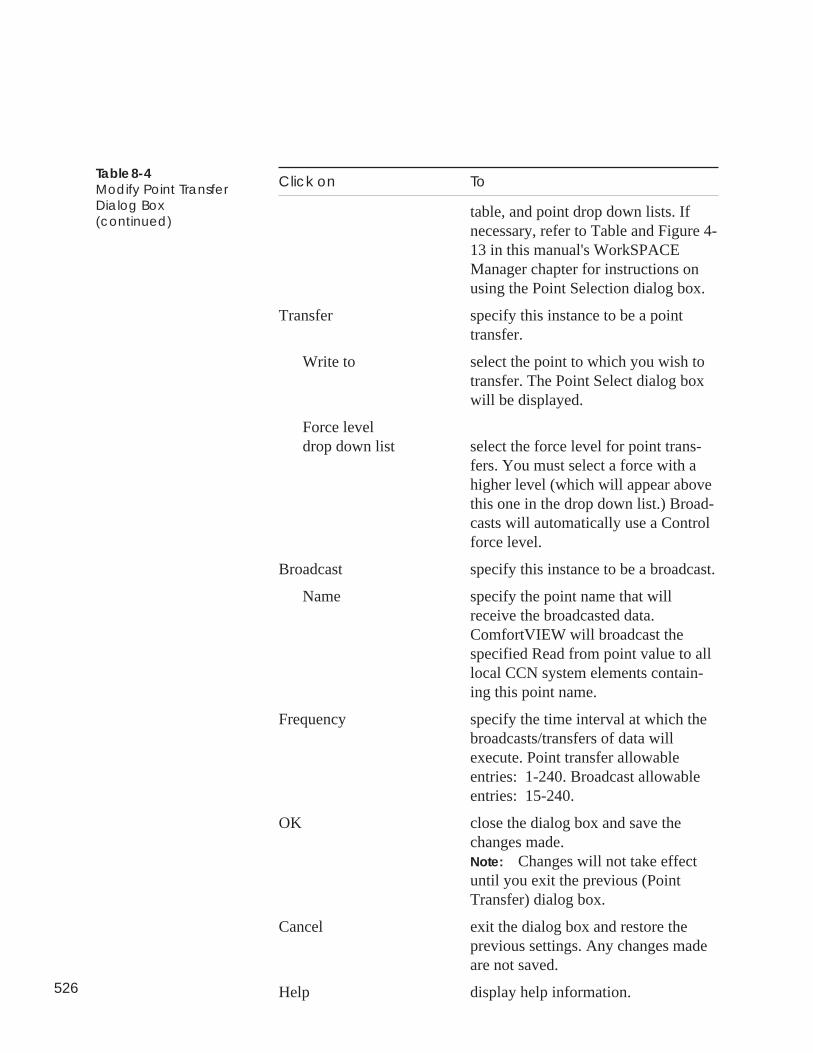
526
Click on To
table, and point drop down lists. Ifnecessary, refer to Table and Figure 4-13 in this manual's WorkSPACEManager chapter for instructions onusing the Point Selection dialog box.
Transfer specify this instance to be a pointtransfer.
Write to select the point to which you wish totransfer. The Point Select dialog boxwill be displayed.
Force leveldrop down list select the force level for point trans-
fers. You must select a force with ahigher level (which will appear abovethis one in the drop down list.) Broad-casts will automatically use a Controlforce level.
Broadcast specify this instance to be a broadcast.
Name specify the point name that willreceive the broadcasted data.ComfortVIEW will broadcast thespecified Read from point value to alllocal CCN system elements contain-ing this point name.
Frequency specify the time interval at which thebroadcasts/transfers of data willexecute. Point transfer allowableentries: 1-240. Broadcast allowableentries: 15-240.
OK close the dialog box and save thechanges made.Note: Changes will not take effectuntil you exit the previous (PointTransfer) dialog box.
Cancel exit the dialog box and restore theprevious settings. Any changes madeare not saved.
Help display help information.
Table 8-4Modify Point TransferDialog Box(continued)
527
A ComfortVIEW server that has been configured to be a timebroadcaster (using the Enable Time Broadcast decision in theCarrier Network Manager's Standard CCN Settings dialog box) willsend holiday status, along with the time, date, and day-of-week,when broadcasting to all locally-connected CCNs. The holidayswhich will be sent are read from the group of holidays that youspecify here by selecting the Functions menu's Holiday tablescommand.
Selecting this command displays the Holidays dialog box. Use thisdialog box to select each holiday by clicking on a day in the calen-dar. Select the month and year using the scroll bar.
For a list of all currently-configured holidays, select the File menu'sPrint command.
The Global Function Manager gives you the ability to create masteroccupancy (time) schedules and to link these schedules to up to 100existing occupancy schedules in specified CCN system elements onany locally-connected CCN. If desired, you can also create anoverride schedule that will supersede the master schedule on aspecified day. Once a day (or when you manually select Download),ComfortVIEW will download the master and any associated over-ride time schedules to the specified system elements, override theexisting controller time schedules, and then update the localComfortVIEW database to match the newly-changed controllerdatabases. This function would be helpful in those situations, forexample, where there are a large number of CCN controllers in afacility to allow you to quickly change all occupancy schedules atonce.
Follow the steps below to create a global occupancy schedule.
1. Click on the Functions menu item and then click on CentralTime Schedule.
The Central Time Schedules dialog box is displayed. Refer toFigure and Table 8-5. This directory-tree structured dialogbox displays the names of all currently-existent master occu-pancy schedules. Double-clicking on the name of a masterschedule displays the categories Links and Overrides.
Holiday Broadcast
Central TimeSchedules
528
Double-click on either one of these categories to display thenames of the associated link and override schedules.
2. In the Central Time Schedules dialog box, you can do thefollowing:
• Define a new master time schedule by clicking on theheader Central time schedules and then clicking on New.The Master Time Schedule dialog box will be displayed.Refer to Figure and Table 8-6. Click to enable/disabledays of the week, and enter the Occupied From and Totimes in the corresponding edit boxes. The bar graph willupdate to display the occupied times.
• Create a new controller time schedule link or a newoverride schedule by clicking on the name of an existingmaster schedule and then clicking on New. The Link/Override dialog box will be displayed. Refer to Figureand Table 8-7. Select either Link or Override.
You could also create a new link or override by expand-ing the directory tree, clicking on Links or Overrides, andthen clicking on New.
• Modify an existing master, link, or override schedule byclicking on the name of the master, link, or overrideschedule and then clicking on Modify. If you are modify-ing a link, the Select Table dialog box will be displayed.If you are modifying a master or override schedule, theMaster Time Schedule or Override Schedule dialog boxwill be displayed. Refer to Figure and Table 8-6.
• Download a master schedule to all associated links andoverride schedules, if appropriate, by clicking on thename of the central schedule and then clicking on Down-load.
• Delete an existing master, override, or linked schedule byclicking on the schedule, override, or link name and thenclicking on Delete. In the confirmation dialog box, clickon Yes to delete the schedule, or on No to close the dialogbox without completing the deletion.
3. Click on OK to close the Central Time Schedules dialog boxand save your settings, or on Cancel to close the dialog boxwithout saving settings.
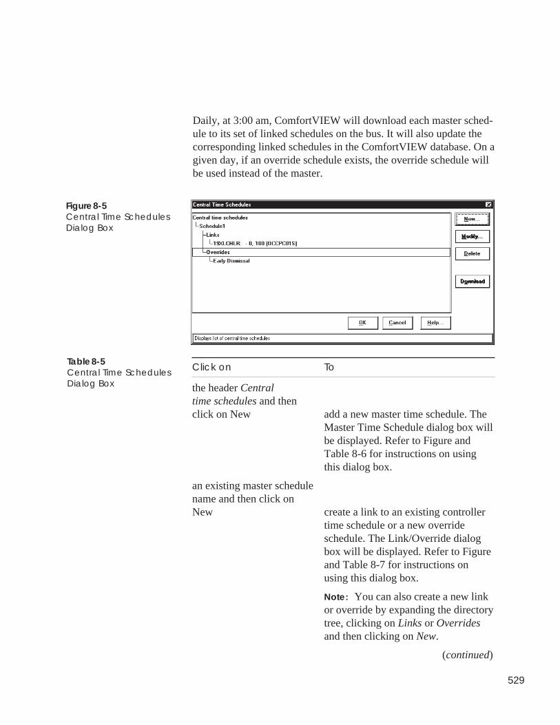
529
Daily, at 3:00 am, ComfortVIEW will download each master sched-ule to its set of linked schedules on the bus. It will also update thecorresponding linked schedules in the ComfortVIEW database. On agiven day, if an override schedule exists, the override schedule willbe used instead of the master.
Figure 8-5Central Time SchedulesDialog Box
Click on To
the header Centraltime schedules and thenclick on New add a new master time schedule. The
Master Time Schedule dialog box willbe displayed. Refer to Figure andTable 8-6 for instructions on usingthis dialog box.
an existing master schedulename and then click onNew create a link to an existing controller
time schedule or a new overrideschedule. The Link/Override dialogbox will be displayed. Refer to Figureand Table 8-7 for instructions onusing this dialog box.
Note: You can also create a new linkor override by expanding the directorytree, clicking on Links or Overridesand then clicking on New.
(continued)
Table 8-5Central Time SchedulesDialog Box
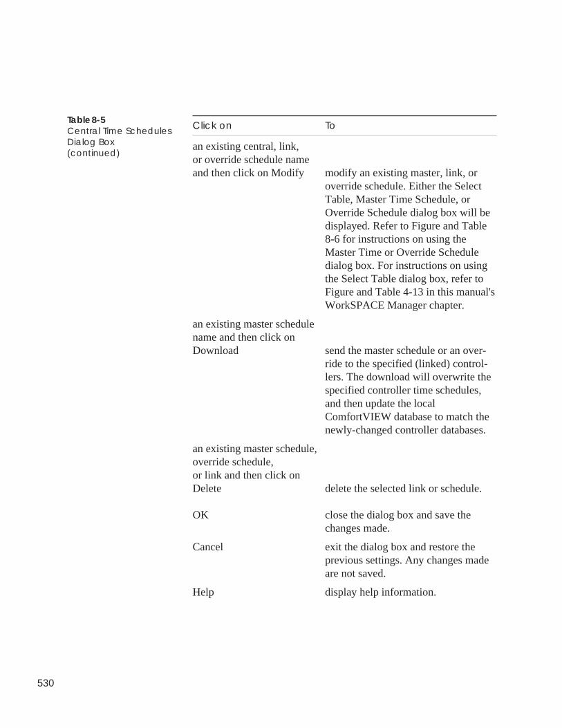
530
Click on To
an existing central, link,or override schedule nameand then click on Modify modify an existing master, link, or
override schedule. Either the SelectTable, Master Time Schedule, orOverride Schedule dialog box will bedisplayed. Refer to Figure and Table8-6 for instructions on using theMaster Time or Override Scheduledialog box. For instructions on usingthe Select Table dialog box, refer toFigure and Table 4-13 in this manual'sWorkSPACE Manager chapter.
an existing master schedulename and then click onDownload send the master schedule or an over-
ride to the specified (linked) control-lers. The download will overwrite thespecified controller time schedules,and then update the localComfortVIEW database to match thenewly-changed controller databases.
an existing master schedule,override schedule,or link and then click onDelete delete the selected link or schedule.
OK close the dialog box and save thechanges made.
Cancel exit the dialog box and restore theprevious settings. Any changes madeare not saved.
Help display help information.
Table 8-5Central Time SchedulesDialog Box(continued)
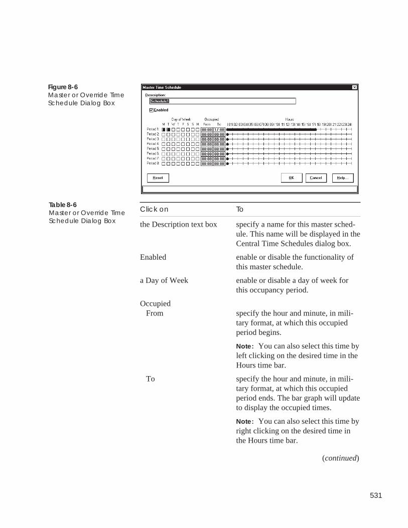
531
Figure 8-6Master or Override TimeSchedule Dialog Box
Click on To
the Description text box specify a name for this master sched-ule. This name will be displayed in theCentral Time Schedules dialog box.
Enabled enable or disable the functionality ofthis master schedule.
a Day of Week enable or disable a day of week forthis occupancy period.
OccupiedFrom specify the hour and minute, in mili-
tary format, at which this occupiedperiod begins.
Note: You can also select this time byleft clicking on the desired time in theHours time bar.
To specify the hour and minute, in mili-tary format, at which this occupiedperiod ends. The bar graph will updateto display the occupied times.
Note: You can also select this time byright clicking on the desired time inthe Hours time bar.
(continued)
Table 8-6Master or Override TimeSchedule Dialog Box
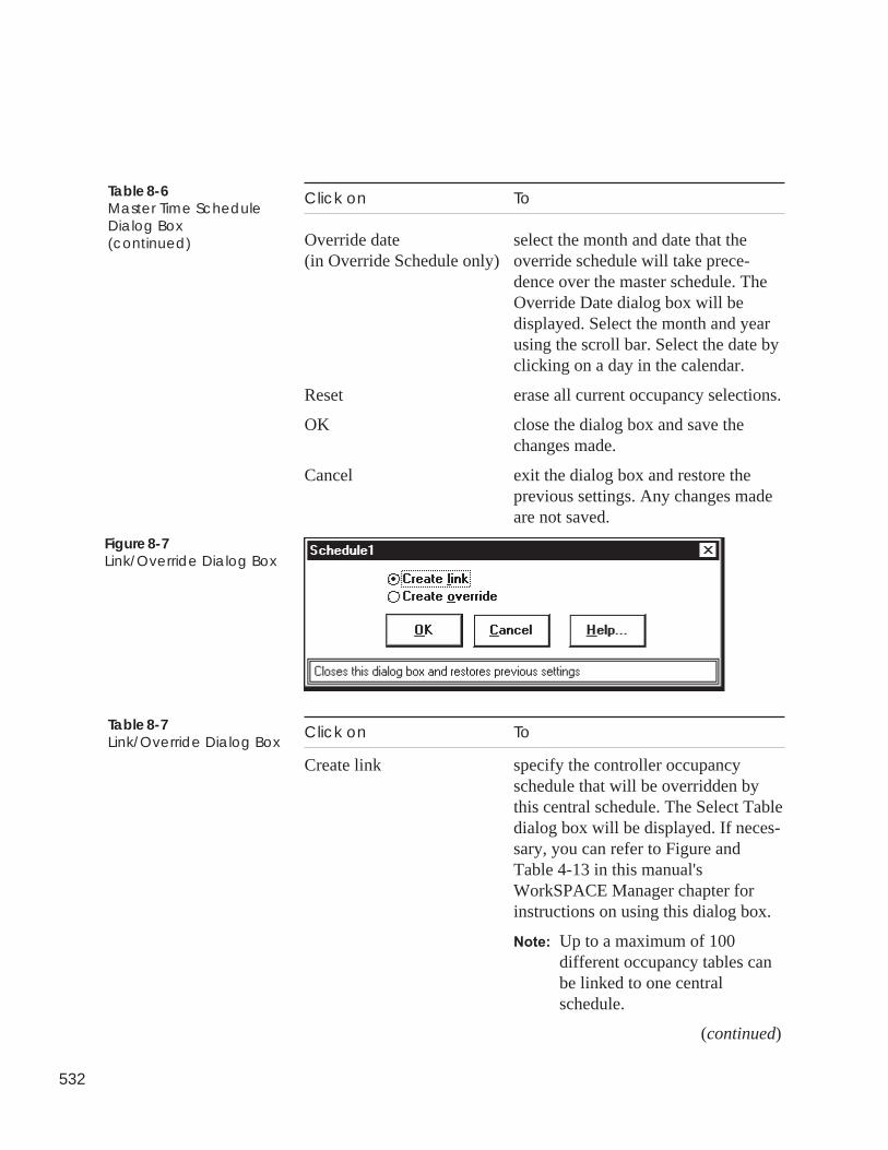
532
Click on To
Override date select the month and date that the(in Override Schedule only) override schedule will take prece-
dence over the master schedule. TheOverride Date dialog box will bedisplayed. Select the month and yearusing the scroll bar. Select the date byclicking on a day in the calendar.
Reset erase all current occupancy selections.
OK close the dialog box and save thechanges made.
Cancel exit the dialog box and restore theprevious settings. Any changes madeare not saved.
Help display help information.
Table 8-6Master Time ScheduleDialog Box(continued)
Figure 8-7Link/Override Dialog Box
Click on To
Create link specify the controller occupancyschedule that will be overridden bythis central schedule. The Select Tabledialog box will be displayed. If neces-sary, you can refer to Figure andTable 4-13 in this manual'sWorkSPACE Manager chapter forinstructions on using this dialog box.
Note: Up to a maximum of 100different occupancy tables canbe linked to one centralschedule.
(continued)
Table 8-7Link/Override Dialog Box
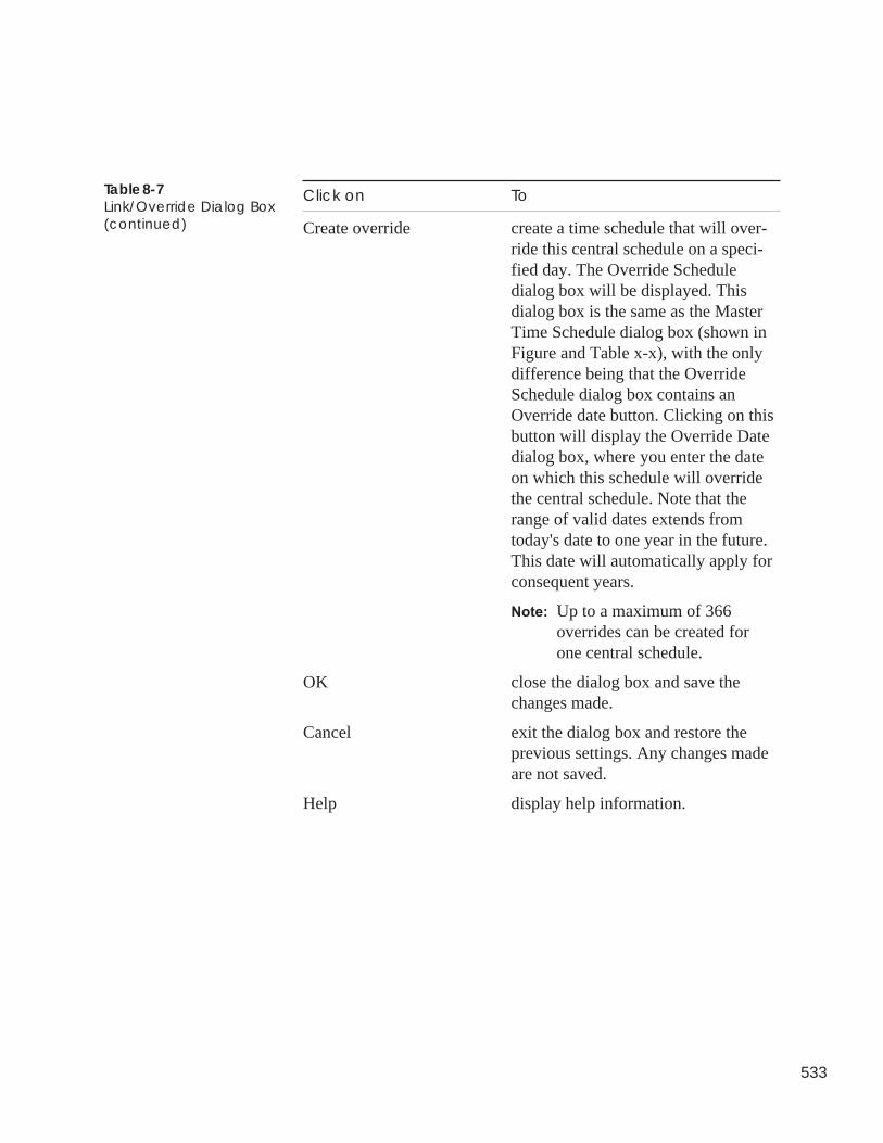
533
Click on To
Create override create a time schedule that will over-ride this central schedule on a speci-fied day. The Override Scheduledialog box will be displayed. Thisdialog box is the same as the MasterTime Schedule dialog box (shown inFigure and Table x-x), with the onlydifference being that the OverrideSchedule dialog box contains anOverride date button. Clicking on thisbutton will display the Override Datedialog box, where you enter the dateon which this schedule will overridethe central schedule. Note that therange of valid dates extends fromtoday's date to one year in the future.This date will automatically apply forconsequent years.
Note: Up to a maximum of 366overrides can be created forone central schedule.
OK close the dialog box and save thechanges made.
Cancel exit the dialog box and restore theprevious settings. Any changes madeare not saved.
Help display help information.
Table 8-7Link/Override Dialog Box(continued)
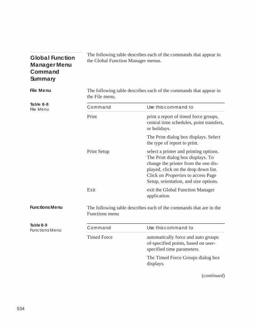
534
The following table describes each of the commands that appear inthe Global Function Manager menus.
The following table describes each of the commands that appear inthe File menu.
Command Use this command to
Print print a report of timed force groups,central time schedules, point transfers,or holidays.
The Print dialog box displays. Selectthe type of report to print.
Print Setup select a printer and printing options.The Print dialog box displays. Tochange the printer from the one dis-played, click on the drop down list.Click on Properties to access PageSetup, orientation, and size options.
Exit exit the Global Function Managerapplication.
The following table describes each of the commands that are in theFunctions menu
Command Use this command to
Timed Force automatically force and auto groupsof-specified points, based on user-specified time parameters.
The Timed Force Groups dialog boxdisplays.
(continued)
Global FunctionManager MenuCommandSummary
File Menu
Table 8-8File Menu
Functions Menu
Table 8-9Functions Menu
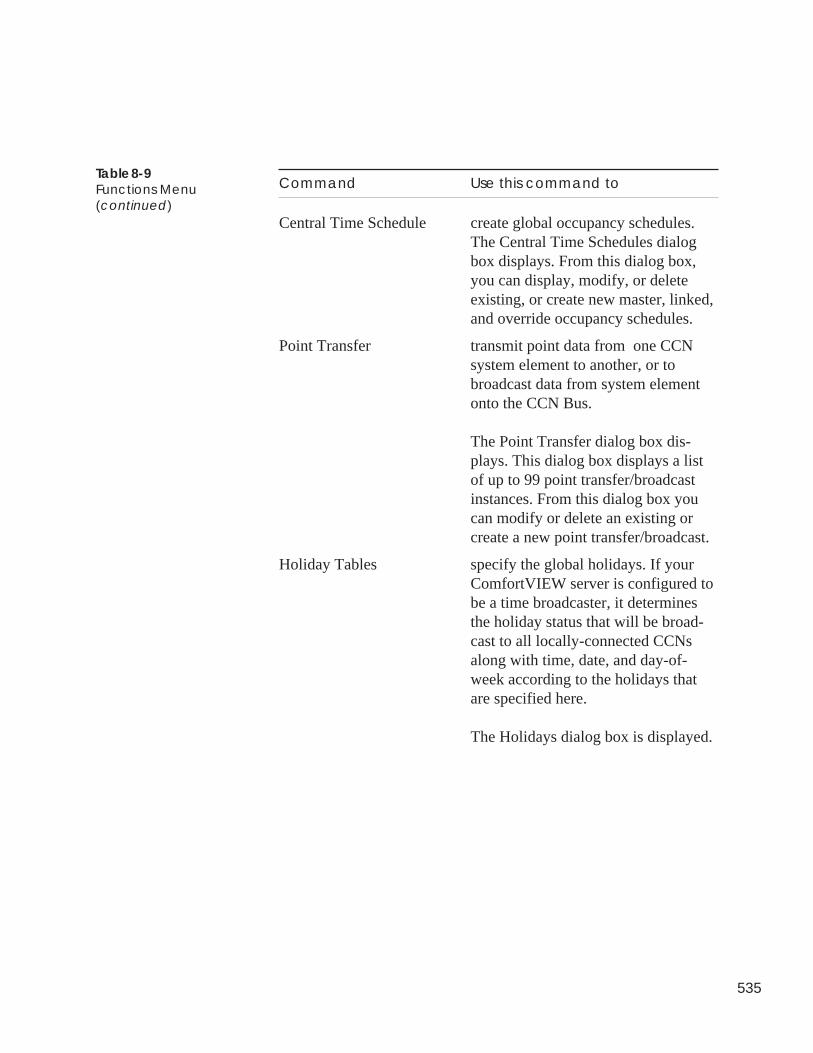
535
Command Use this command to
Central Time Schedule create global occupancy schedules.The Central Time Schedules dialogbox displays. From this dialog box,you can display, modify, or deleteexisting, or create new master, linked,and override occupancy schedules.
Point Transfer transmit point data from one CCNsystem element to another, or tobroadcast data from system elementonto the CCN Bus.
The Point Transfer dialog box dis-plays. This dialog box displays a listof up to 99 point transfer/broadcastinstances. From this dialog box youcan modify or delete an existing orcreate a new point transfer/broadcast.
Holiday Tables specify the global holidays. If yourComfortVIEW server is configured tobe a time broadcaster, it determinesthe holiday status that will be broad-cast to all locally-connected CCNsalong with time, date, and day-of-week according to the holidays thatare specified here.
The Holidays dialog box is displayed.
Table 8-9Functions Menu(continued)

536
The following table describes each of the commands in the Helpmenu.
Command Use this command to
Contents display the help table of contents.
Search search for a help topic by typing akeyword.
About display program information, versioninformation on all ComfortVIEWcomponents, and copyright.
Help Menu
Table 8-10Help Menu

BEST++

Alarm Manager
537
The ComfortVIEW BEST++ application gives you access toCarrier's Building Environmental Systems Translator (BEST++)custom programming language. This easy-to-use programminglanguage gives you the ability to write programs to supplement orenhance the standard control algorithms that are resident in Carrier'sComfort Controllers.
Instructions on operating the ComfortVIEW BEST++ applicationare included in Appendix D of the BEST++ Programmer's Refer-ence Manual (808-893). This manual can be ordered from CarrierLiterature Distribution.
ComfortVIEWBEST++

538

Appendixes

Alarm Manager
539
Consumable, runtime, and history reports are described in thismanual's Report Panel chapter. Other report types that are availableto you are described in Table A-1 below.
Report Type Contents
System Activity ComfortVIEW "system-type" events;refer to Table A-4 for a list of theevents that can be reported.
Alarm Summary Selected alarm information
Time Schedule Controller-by-controller occupancyschedules and associated points
Tenant Billing Timed overrides and resulting charges
To produce any of these reports, you need to first create a reportdefinition, and then generate the report. The remainder of thisappendix describes how to create report definitions for each of theabove report types; see the Report Panel chapter for instructions ongenerating reports.
Follow these steps to create a report definition for a System Activityreport:
1. Launch the Report Panel application by double-clicking onthe Report Panel icon (shown at left).
2. Double-click on the System Activity icon (shown at left). Youwill see a list of the existing System Activity report definitions.
3. Click on the File menu item, then click on New. You can alsoclick on the Add New Report tool bar icon (shown at left).
ComfortVIEW displays a Report Definition dialog box,shown in Figure A-2.
3. Use the Report Definition dialog box to enter the following:
• Report Name and Description• Manual Generation or Automatic Retrieval Options• Report Dates
Refer to Figure A-2 and Table A-2 for instructions on usingthe Report Definition dialog box.
Table A-1Additional Reports
Appendix A— AdditionalComfortVIEWReports
Defining a SystemActivity Report
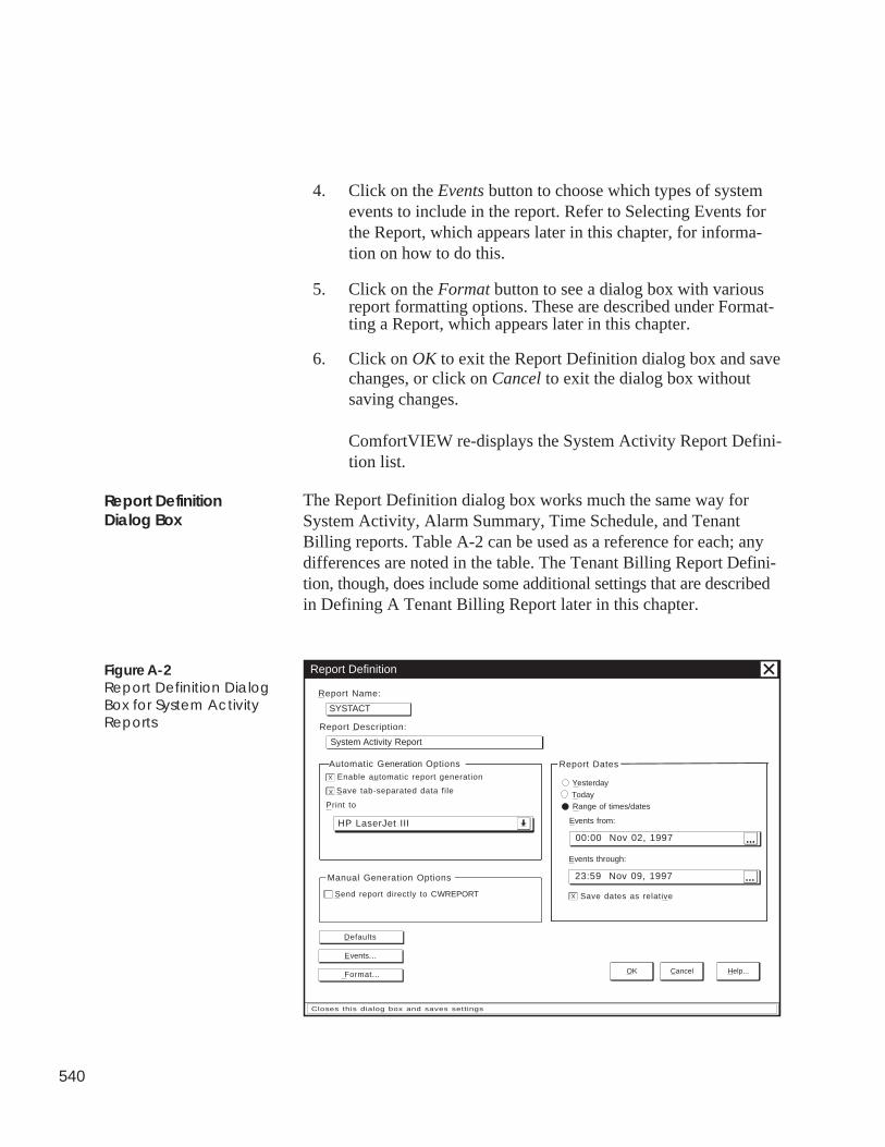
540
4. Click on the Events button to choose which types of systemevents to include in the report. Refer to Selecting Events forthe Report, which appears later in this chapter, for informa-tion on how to do this.
5. Click on the Format button to see a dialog box with variousreport formatting options. These are described under Format-ting a Report, which appears later in this chapter.
6. Click on OK to exit the Report Definition dialog box and savechanges, or click on Cancel to exit the dialog box withoutsaving changes.
ComfortVIEW re-displays the System Activity Report Defini-tion list.
The Report Definition dialog box works much the same way forSystem Activity, Alarm Summary, Time Schedule, and TenantBilling reports. Table A-2 can be used as a reference for each; anydifferences are noted in the table. The Tenant Billing Report Defini-tion, though, does include some additional settings that are describedin Defining A Tenant Billing Report later in this chapter.
Report Definition
Report Name:
SYSTACT
Report Description:
System Activity Report
Automatic Generation OptionsEnable automatic report generation
HP LaserJet III
Save tab-separated data file
Print to
X
X
Send report directly to CWREPORT
Manual Generation Options
Format...
Events...
Defaults
00:00 Nov 02, 1997
Events from:
Report Dates
23:59 Nov 09, 1997
Events through:
Save dates as relative
X
Range of times/dates
Yesterday
Today
OK Cancel Help...
Closes this dialog box and saves settings
. . .
. . .
Report DefinitionDialog Box
Figure A-2Report Definition DialogBox for System ActivityReports
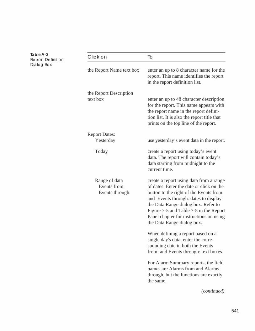
541
Click on To
the Report Name text box enter an up to 8 character name for thereport. This name identifies the reportin the report definition list.
the Report Descriptiontext box enter an up to 48 character description
for the report. This name appears withthe report name in the report defini-tion list. It is also the report title thatprints on the top line of the report.
Report Dates:Yesterday use yesterday’s event data in the report.
Today create a report using today’s eventdata. The report will contain today’sdata starting from midnight to thecurrent time.
Range of data create a report using data from a range Events from: of dates. Enter the date or click on the Events through: button to the right of the Events from:
and Events through: dates to displaythe Data Range dialog box. Refer toFigure 7-5 and Table 7-5 in the ReportPanel chapter for instructions on usingthe Data Range dialog box.
When defining a report based on asingle day's data, enter the corre-sponding date in both the Eventsfrom: and Events through: text boxes.
For Alarm Summary reports, the fieldnames are Alarms from and Alarmsthrough, but the functions are exactlythe same.
(continued)
Table A-2Report DefinitionDialog Box
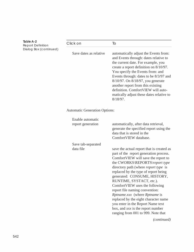
542
Click on To
Save dates as relative automatically adjust the Events from:and Events through: dates relative tothe current date. For example, youcreate a report definition on 8/10/97.You specify the Events from: andEvents through: dates to be 8/3/97 and8/10/97. On 8/18/97, you generateanother report from this existingdefinition. ComfortVIEW will auto-matically adjust these dates relative to8/18/97.
Automatic Generation Options:
Enable automaticreport generation automatically, after data retrieval,
generate the specified report using thedata that is stored in theComfortVIEW database.
Save tab-separateddata file save the actual report that is created as
part of the report generation process.ComfortVIEW will save the report tothe CWORKS\REPORTS\report typedirectory path (where report type isreplaced by the type of report beinggenerated: CONSUME, HISTORY,RUNTIME, SYSTACT, etc.).ComfortVIEW uses the followingreport file naming convention:Rptname.xxx (where Rptname isreplaced by the eight character nameyou enter in the Report Name textbox, and xxx is the report numberranging from 001 to 999. Note that
(continued)
Table A-2Report DefinitionDialog Box (continued)
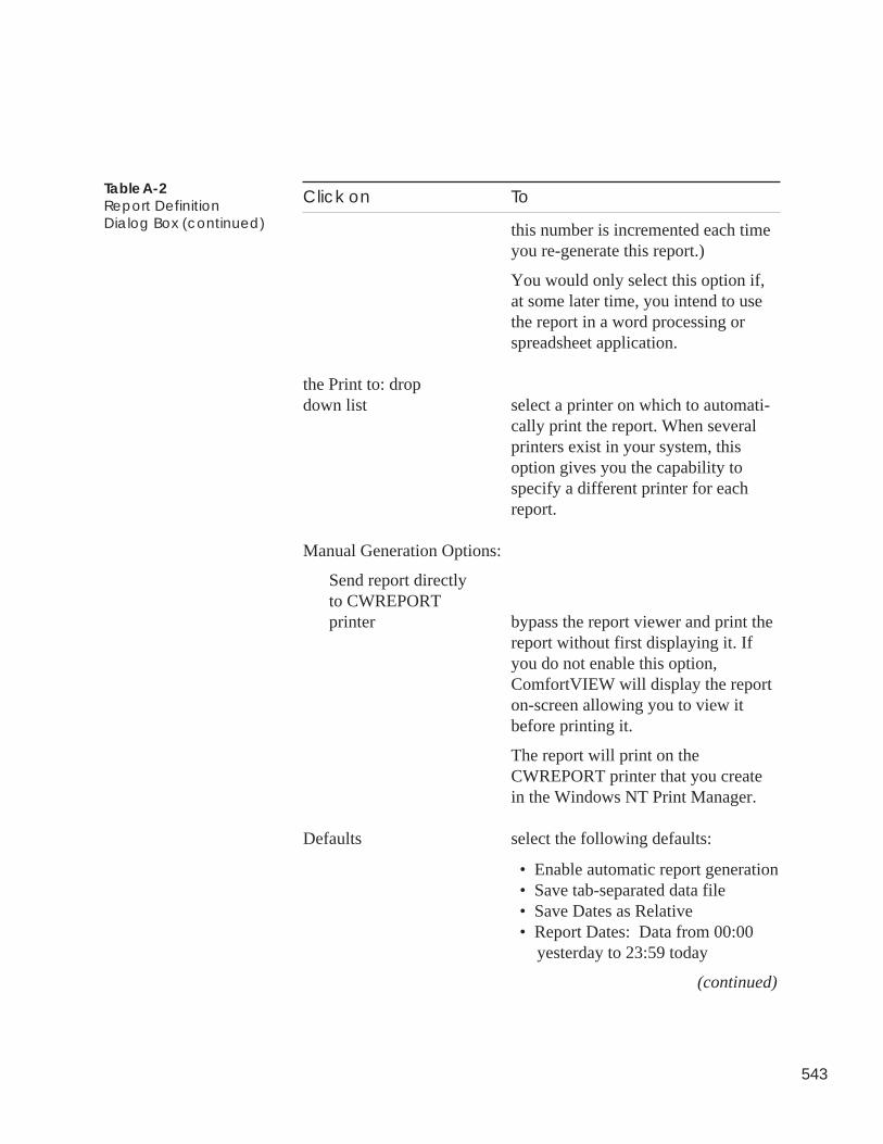
543
Click on To
this number is incremented each timeyou re-generate this report.)
You would only select this option if,at some later time, you intend to usethe report in a word processing orspreadsheet application.
the Print to: dropdown list select a printer on which to automati-
cally print the report. When severalprinters exist in your system, thisoption gives you the capability tospecify a different printer for eachreport.
Manual Generation Options:
Send report directlyto CWREPORTprinter bypass the report viewer and print the
report without first displaying it. Ifyou do not enable this option,ComfortVIEW will display the reporton-screen allowing you to view itbefore printing it.
The report will print on theCWREPORT printer that you createin the Windows NT Print Manager.
Defaults select the following defaults:
• Enable automatic report generation • Save tab-separated data file • Save Dates as Relative • Report Dates: Data from 00:00 yesterday to 23:59 today
(continued)
Table A-2Report DefinitionDialog Box (continued)
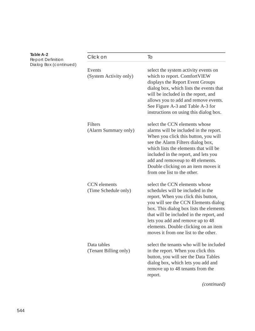
544
Click on To
Events select the system activity events on(System Activity only) which to report. ComfortVIEW
displays the Report Event Groupsdialog box, which lists the events thatwill be included in the report, andallows you to add and remove events.See Figure A-3 and Table A-3 forinstructions on using this dialog box.
Filters select the CCN elements whose(Alarm Summary only) alarms will be included in the report.
When you click this button, you willsee the Alarm Filters dialog box,which lists the elements that will beincluded in the report, and lets youadd and removeup to 48 elements.Double clicking on an item moves itfrom one list to the other.
CCN elements select the CCN elements whose(Time Schedule only) schedules will be included in the
report. When you click this button,you will see the CCN Elements dialogbox. This dialog box lists the elementsthat will be included in the report, andlets you add and remove up to 48elements. Double clicking on an itemmoves it from one list to the other.
Data tables select the tenants who will be included(Tenant Billing only) in the report. When you click this
button, you will see the Data Tablesdialog box, which lets you add andremove up to 48 tenants from thereport.
(continued)
Table A-2Report DefinitionDialog Box (continued)
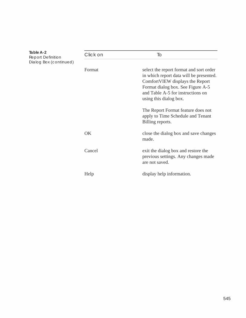
545
Click on To
Format select the report format and sort orderin which report data will be presented.ComfortVIEW displays the ReportFormat dialog box. See Figure A-5and Table A-5 for instructions onusing this dialog box.
The Report Format feature does notapply to Time Schedule and TenantBilling reports.
OK close the dialog box and save changesmade.
Cancel exit the dialog box and restore theprevious settings. Any changes madeare not saved.
Help display help information.
Table A-2Report DefinitionDialog Box (continued)
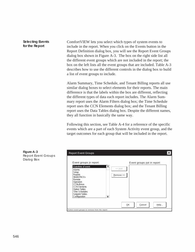
546
ComfortVIEW lets you select which types of system events toinclude in the report. When you click on the Events button in theReport Definition dialog box, you will see the Report Event Groupsdialog box shown in Figure A-3. The box on the right side list allthe different event groups which are not included in the report; thebox on the left lists all the event groups that are included. Table A-3describes how to use the different controls in the dialog box to builda list of event groups to include.
Alarm Summary, Time Schedule, and Tenant Billing reports all usesimilar dialog boxes to select elements for their reports. The maindifference is that the labels within the box are different, reflectingthe different types of data each report includes. The Alarm Sum-mary report uses the Alarm Filters dialog box; the Time Schedulereport uses the CCN Elements dialog box; and the Tenant Billingreport uses the Data Tables dialog box. Despite the different names,they all function in basically the same way.
Following this section, see Table A-4 for a reference of the specificevents which are a part of each System Activity event group, and thetarget outcomes for each group that will be included in the report.
Selecting Eventsfor the Report
Event groups in report:
Date/time of event
Report Event Groups
Select event groups to remove from the report
<< Add
Remove >>
Event groups not in report:
AlarmsSetupReportsWorkSPACEsRemoteOperatorsCCNs/AreasCCN ElementsOption TablesTime SchedulesSetpoint TablesConfiguration
OK Cancel Help...
Figure A-3Report Event GroupsDialog Box
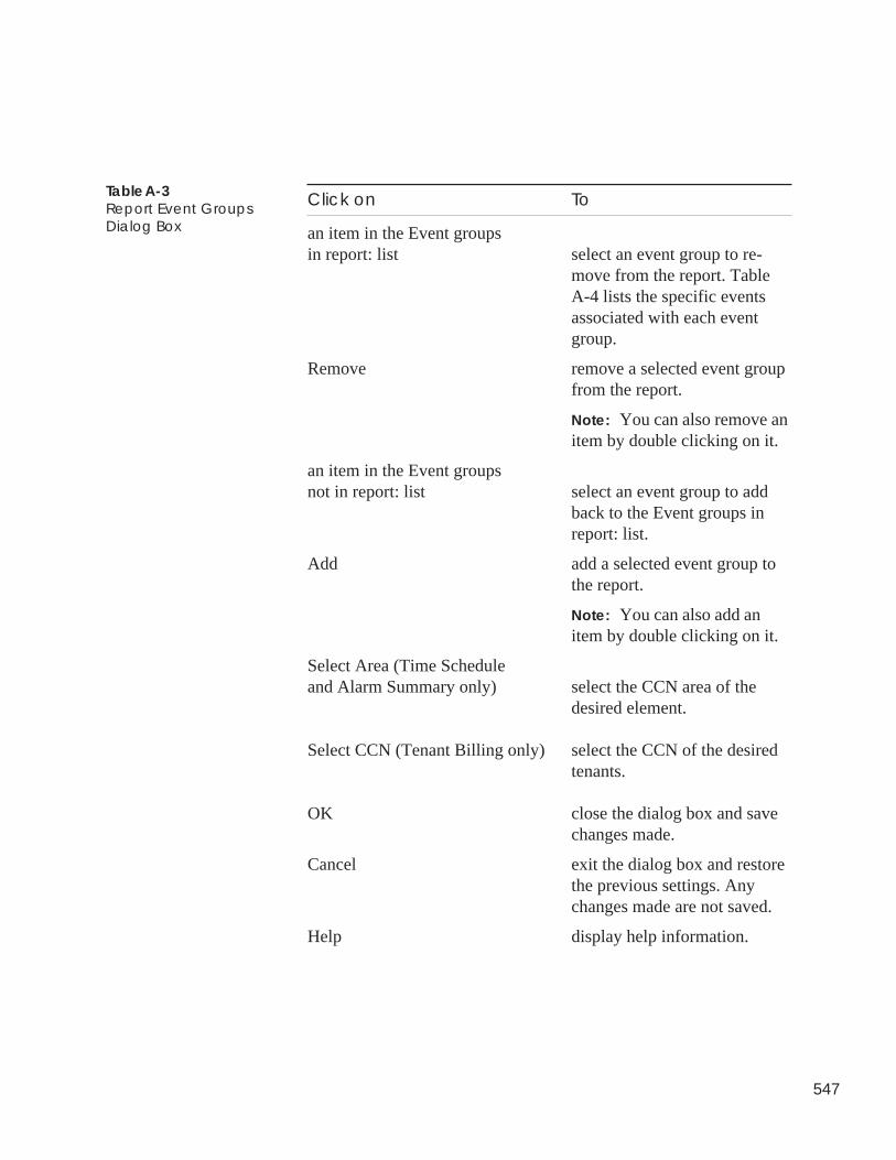
547
Click on To
an item in the Event groupsin report: list select an event group to re-
move from the report. TableA-4 lists the specific eventsassociated with each eventgroup.
Remove remove a selected event groupfrom the report.
Note: You can also remove anitem by double clicking on it.
an item in the Event groupsnot in report: list select an event group to add
back to the Event groups inreport: list.
Add add a selected event group tothe report.
Note: You can also add anitem by double clicking on it.
Select Area (Time Scheduleand Alarm Summary only) select the CCN area of the
desired element.
Select CCN (Tenant Billing only) select the CCN of the desiredtenants.
OK close the dialog box and savechanges made.
Cancel exit the dialog box and restorethe previous settings. Anychanges made are not saved.
Help display help information.
Table A-3Report Event GroupsDialog Box
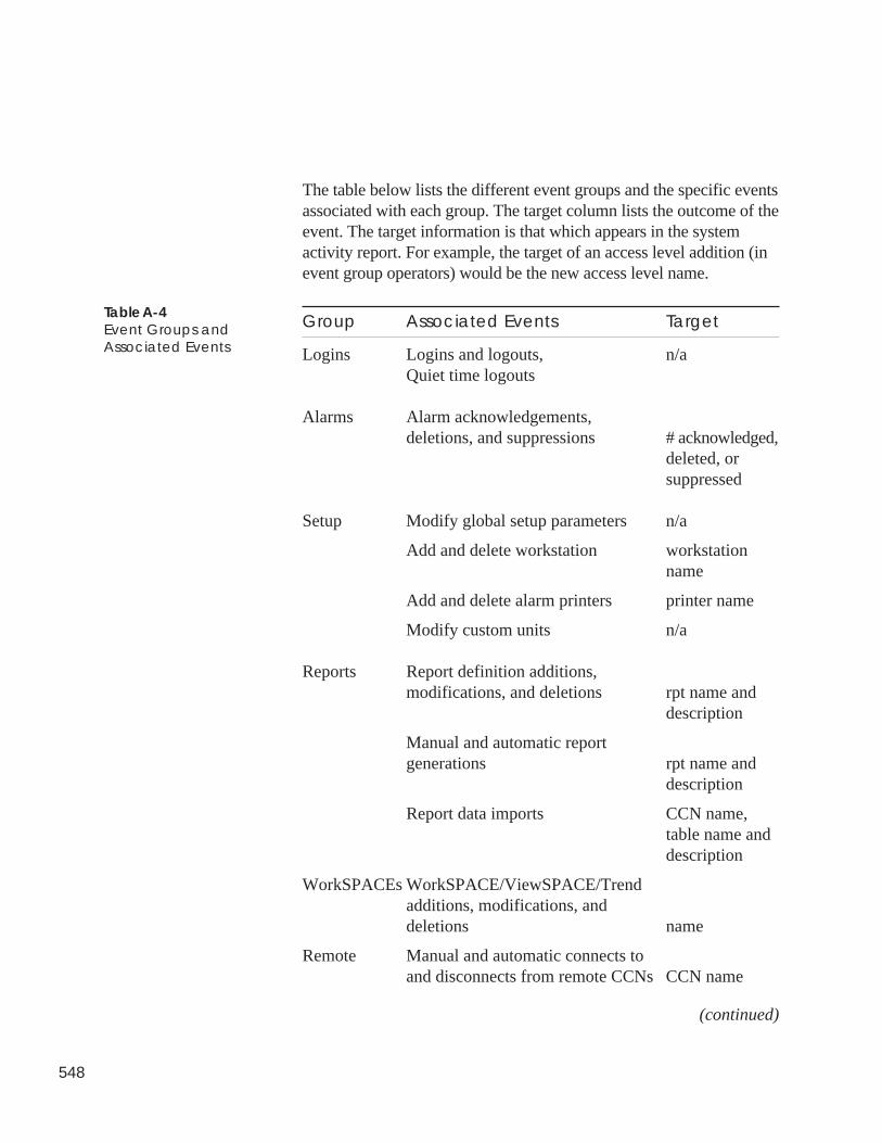
548
The table below lists the different event groups and the specific eventsassociated with each group. The target column lists the outcome of theevent. The target information is that which appears in the systemactivity report. For example, the target of an access level addition (inevent group operators) would be the new access level name.
Group Associated Events Target
Logins Logins and logouts, n/aQuiet time logouts
Alarms Alarm acknowledgements,deletions, and suppressions # acknowledged,
deleted, orsuppressed
Setup Modify global setup parameters n/a
Add and delete workstation workstationname
Add and delete alarm printers printer name
Modify custom units n/a
Reports Report definition additions,modifications, and deletions rpt name and
description
Manual and automatic reportgenerations rpt name and
description
Report data imports CCN name,table name anddescription
WorkSPACEs WorkSPACE/ViewSPACE/Trendadditions, modifications, anddeletions name
Remote Manual and automatic connects toand disconnects from remote CCNs CCN name
(continued)
Table A-4Event Groups andAssociated Events
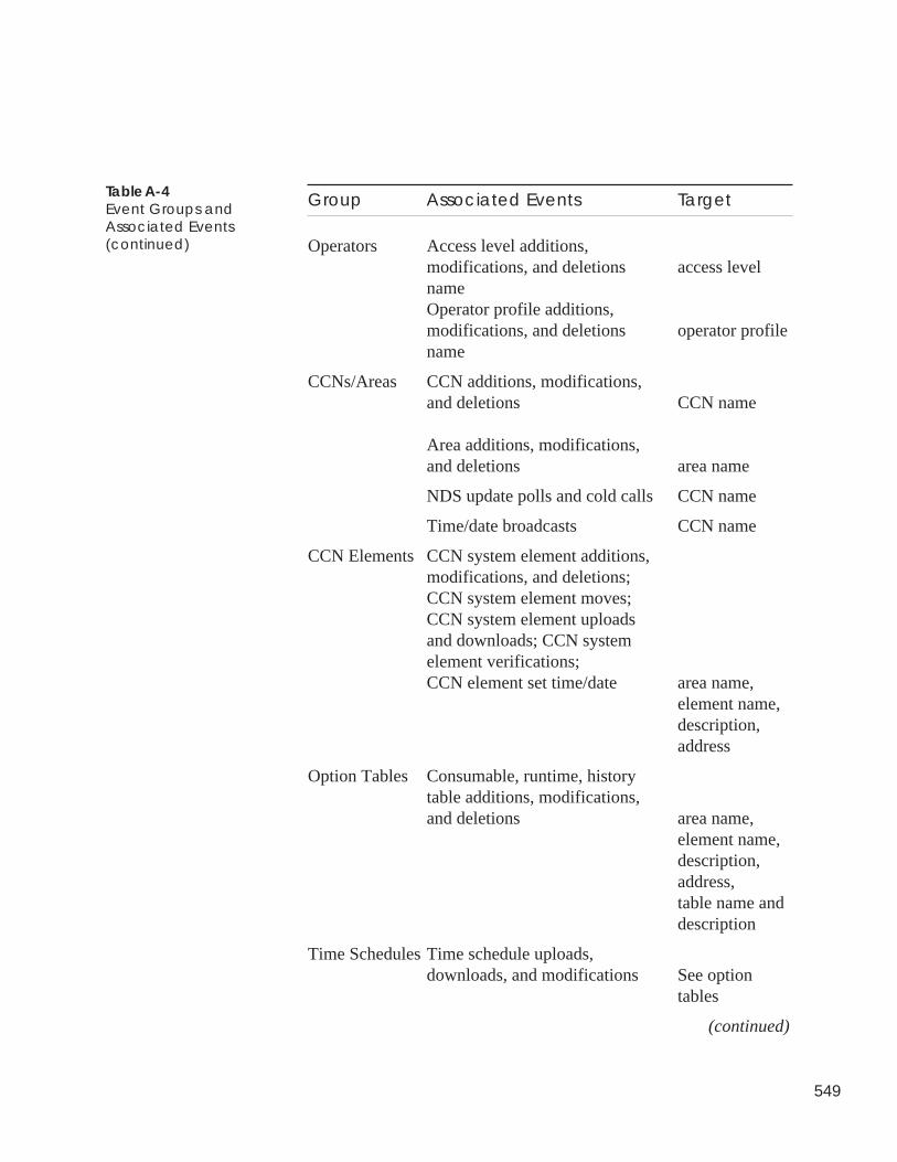
549
Group Associated Events Target
Operators Access level additions,modifications, and deletions access levelnameOperator profile additions,modifications, and deletions operator profilename
CCNs/Areas CCN additions, modifications,and deletions CCN name
Area additions, modifications,and deletions area name
NDS update polls and cold calls CCN name
Time/date broadcasts CCN name
CCN Elements CCN system element additions,modifications, and deletions;CCN system element moves;CCN system element uploadsand downloads; CCN systemelement verifications;CCN element set time/date area name,
element name,description,address
Option Tables Consumable, runtime, historytable additions, modifications,and deletions area name,
element name,description,address,table name anddescription
Time Schedules Time schedule uploads,downloads, and modifications See option
tables
(continued)
Table A-4Event Groups andAssociated Events(continued)
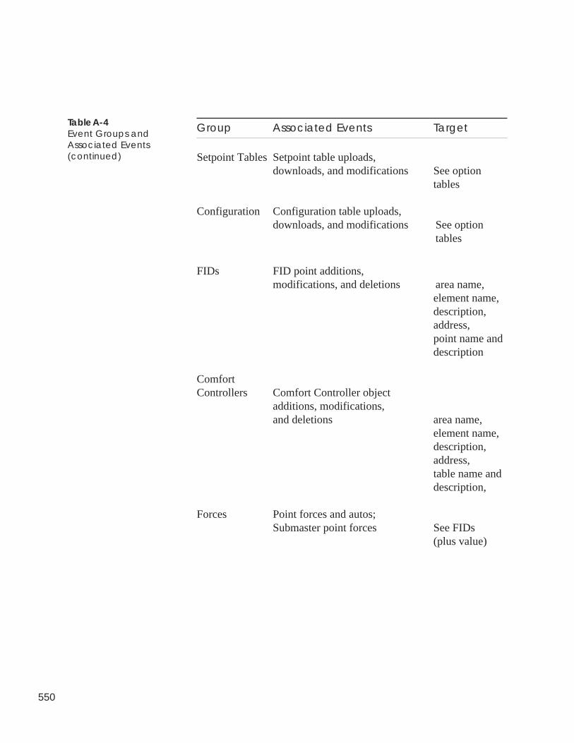
550
Group Associated Events Target
Setpoint Tables Setpoint table uploads,downloads, and modifications See option
tables
Configuration Configuration table uploads,downloads, and modifications See option
tables
FIDs FID point additions,modifications, and deletions area name,
element name,description,address,point name anddescription
ComfortControllers Comfort Controller object
additions, modifications,and deletions area name,
element name,description,address,table name anddescription,
Forces Point forces and autos;Submaster point forces See FIDs
(plus value)
Table A-4Event Groups andAssociated Events(continued)
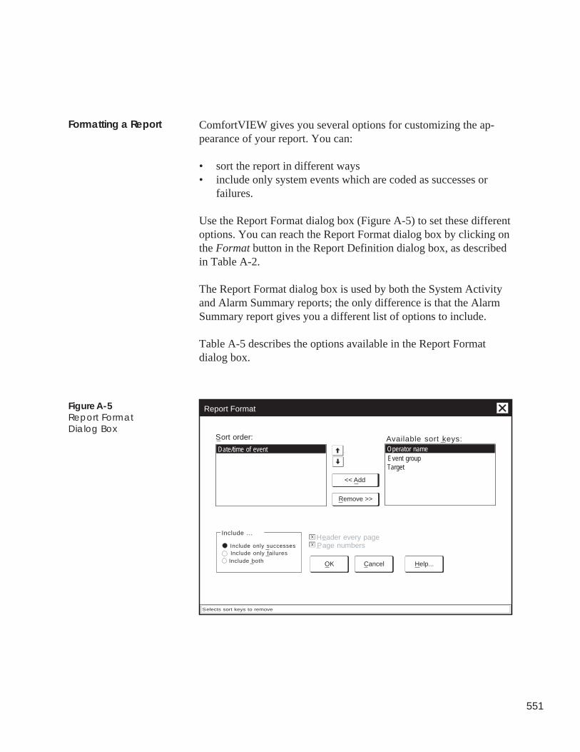
551
ComfortVIEW gives you several options for customizing the ap-pearance of your report. You can:
• sort the report in different ways• include only system events which are coded as successes or
failures.
Use the Report Format dialog box (Figure A-5) to set these differentoptions. You can reach the Report Format dialog box by clicking onthe Format button in the Report Definition dialog box, as describedin Table A-2.
The Report Format dialog box is used by both the System Activityand Alarm Summary reports; the only difference is that the AlarmSummary report gives you a different list of options to include.
Table A-5 describes the options available in the Report Formatdialog box.
Sort order:
<< Add
Remove >>
Date/time of eventEvent groupOperator name
Target
Available sort keys:
OK Cancel Help...
Include ...
Include only successesInclude only failuresInclude both
Header every pagePage numbers
X
X
Report Format
Selects sort keys to remove
Formatting a Report
Figure A-5Report FormatDialog Box
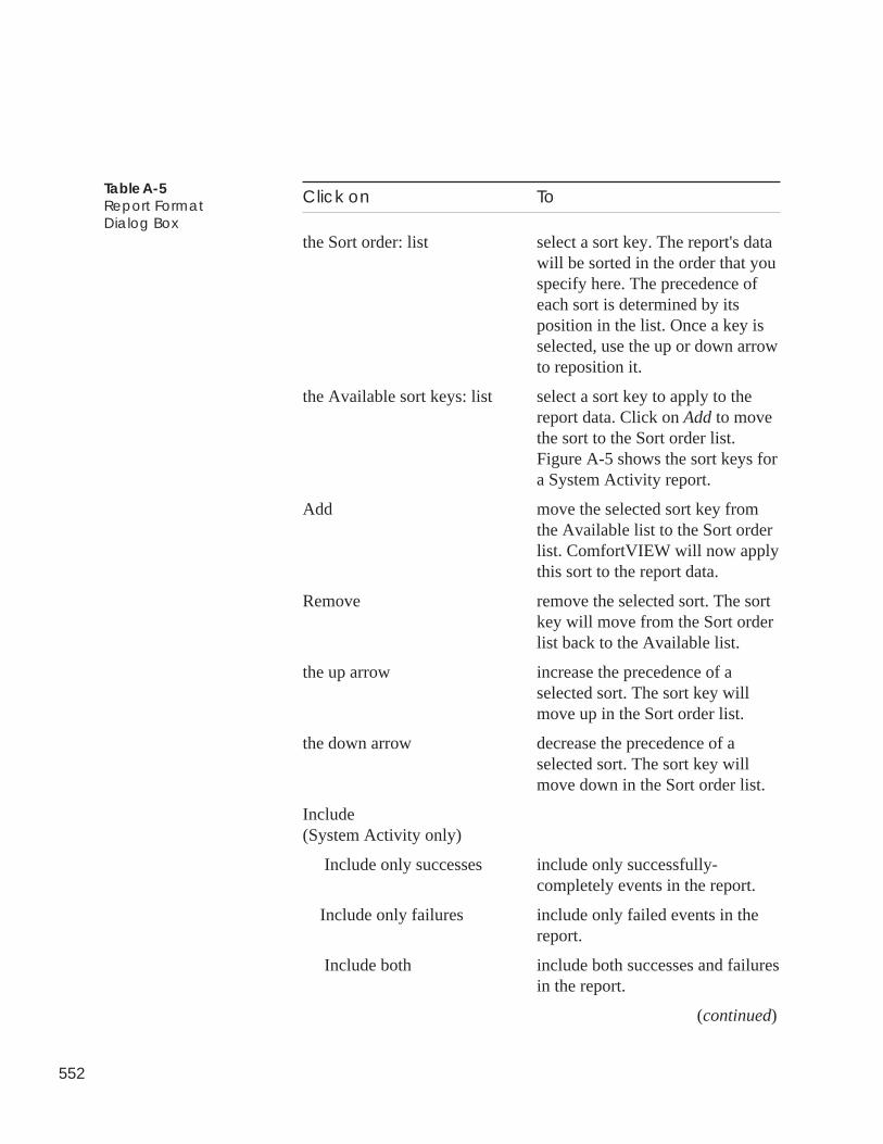
552
Click on To
the Sort order: list select a sort key. The report's datawill be sorted in the order that youspecify here. The precedence ofeach sort is determined by itsposition in the list. Once a key isselected, use the up or down arrowto reposition it.
the Available sort keys: list select a sort key to apply to thereport data. Click on Add to movethe sort to the Sort order list.Figure A-5 shows the sort keys fora System Activity report.
Add move the selected sort key fromthe Available list to the Sort orderlist. ComfortVIEW will now applythis sort to the report data.
Remove remove the selected sort. The sortkey will move from the Sort orderlist back to the Available list.
the up arrow increase the precedence of aselected sort. The sort key willmove up in the Sort order list.
the down arrow decrease the precedence of aselected sort. The sort key willmove down in the Sort order list.
Include(System Activity only)
Include only successes include only successfully-completely events in the report.
Include only failures include only failed events in thereport.
Include both include both successes and failuresin the report.
(continued)
Table A-5Report FormatDialog Box
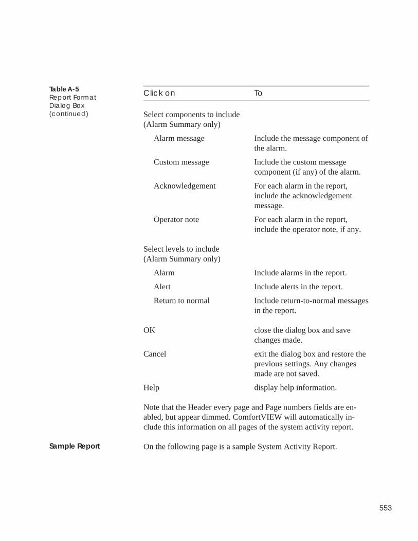
553
Click on To
Select components to include(Alarm Summary only)
Alarm message Include the message component ofthe alarm.
Custom message Include the custom messagecomponent (if any) of the alarm.
Acknowledgement For each alarm in the report,include the acknowledgementmessage.
Operator note For each alarm in the report,include the operator note, if any.
Select levels to include(Alarm Summary only)
Alarm Include alarms in the report.
Alert Include alerts in the report.
Return to normal Include return-to-normal messagesin the report.
OK close the dialog box and savechanges made.
Cancel exit the dialog box and restore theprevious settings. Any changesmade are not saved.
Help display help information.
Note that the Header every page and Page numbers fields are en-abled, but appear dimmed. ComfortVIEW will automatically in-clude this information on all pages of the system activity report.
On the following page is a sample System Activity Report.
Table A-5Report FormatDialog Box(continued)
Sample Report
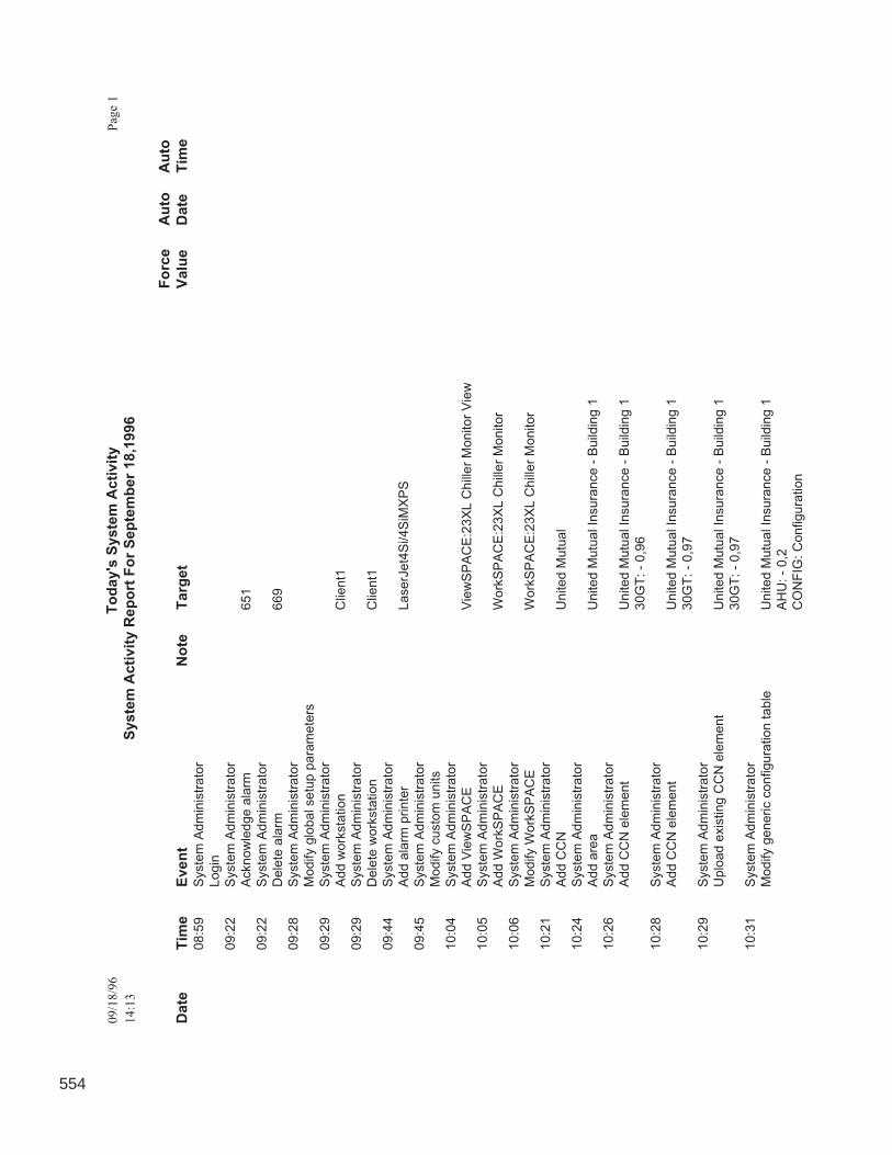
554
09/1
8/9
6T
od
ay's
Syste
m A
cti
vit
yP
age
1
14:1
3S
yste
m A
cti
vit
y R
ep
ort
Fo
r S
ep
tem
ber
18,1
996
Fo
rce
Au
toA
uto
Date
Tim
eE
ven
tN
ote
T
arg
et
Va
lue
Da
teT
ime
08:5
9S
yste
m A
dm
inis
trato
r
Login
09:2
2S
yste
m A
dm
inis
trato
r
Acknow
ledge a
larm
651
09:2
2S
yste
m A
dm
inis
trato
r
Dele
te a
larm
669
09:2
8S
yste
m A
dm
inis
trato
r
Modify g
lobal setu
p p
ara
mete
rs
09:2
9S
yste
m A
dm
inis
trato
r
Add w
ork
sta
tion
Clie
nt1
09:2
9S
yste
m A
dm
inis
trato
r
Dele
te w
ork
sta
tion
Clie
nt1
09:4
4S
yste
m A
dm
inis
trato
r
Add a
larm
printe
rL
ase
rJe
t4S
i/4
SiM
XP
S
09:4
5S
yste
m A
dm
inis
trato
r
Modify c
usto
m u
nits
10:0
4S
yste
m A
dm
inis
trato
r
Add V
iew
SP
AC
EV
iew
SP
AC
E:2
3X
L C
hill
er
Monitor
Vie
w
10:0
5S
yste
m A
dm
inis
trato
r
Add W
ork
SP
AC
EW
ork
SP
AC
E:2
3X
L C
hill
er
Monitor
10:0
6S
yste
m A
dm
inis
trato
r
Modify W
ork
SP
AC
EW
ork
SP
AC
E:2
3X
L C
hill
er
Monitor
10:2
1S
yste
m A
dm
inis
trato
r
Add C
CN
United M
utu
al
10:2
4S
yste
m A
dm
inis
trato
r
Add a
rea
United M
utu
al In
sura
nce -
Build
ing 1
10:2
6S
yste
m A
dm
inis
trato
r
Add C
CN
ele
ment
United M
utu
al In
sura
nce -
Build
ing 1
30G
T: -
0,9
6
10:2
8S
yste
m A
dm
inis
trato
r
Add C
CN
ele
ment
United M
utu
al In
sura
nce -
Build
ing 1
30G
T: -
0,9
7
10:2
9S
yste
m A
dm
inis
trato
r
Uplo
ad e
xis
ting C
CN
ele
ment
United M
utu
al In
sura
nce -
Build
ing 1
30G
T: -
0,9
7
10:3
1S
yste
m A
dm
inis
trato
r
Modify g
eneric c
on
figura
tion t
able
United M
utu
al In
sura
nce -
Build
ing 1
AH
U: -
0,2
CO
NF
IG:
Configura
tion
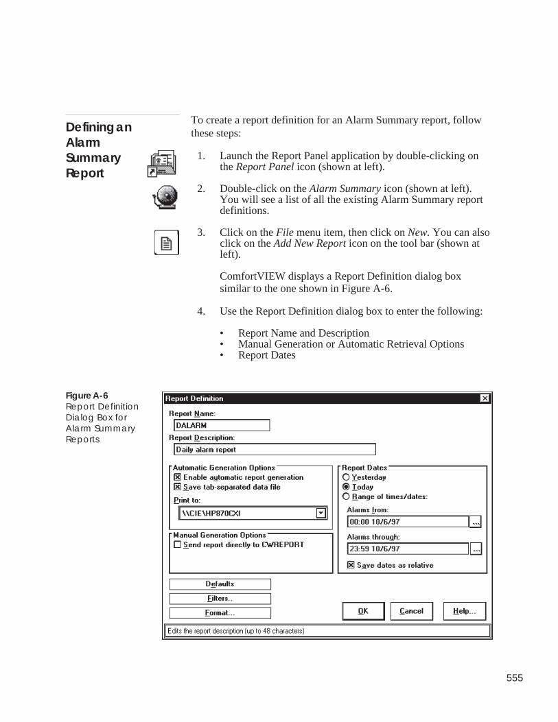
555
To create a report definition for an Alarm Summary report, followthese steps:
1. Launch the Report Panel application by double-clicking onthe Report Panel icon (shown at left).
2. Double-click on the Alarm Summary icon (shown at left).You will see a list of all the existing Alarm Summary reportdefinitions.
3. Click on the File menu item, then click on New. You can alsoclick on the Add New Report icon on the tool bar (shown atleft).
ComfortVIEW displays a Report Definition dialog boxsimilar to the one shown in Figure A-6.
4. Use the Report Definition dialog box to enter the following:
• Report Name and Description• Manual Generation or Automatic Retrieval Options• Report Dates
Defining anAlarmSummaryReport
Figure A-6Report DefinitionDialog Box forAlarm SummaryReports
556
Refer to Table A-2 for instructions on using the ReportDefinition dialog box.
5. Click on the Filters button to displhe Alarm Filters dialog boxwhere you can select the CCN elements whose alarms will beincluded in the report. Double clicking on an item moves itfrom one list to the other.
6. Click on the Format button to set the following report formatoptions:
• Sort the report in different ways• Select which types of alarms to include in the report• Include all of the alarm message or just certain compo-
nents.
Table A-5 in the Formatting a Report section earlier in thischapter describes the Report Format dialog box in detail.
7. Click on OK to exit the dialog box and save changes, or clickon Cancel to exit the dialog box without saving changes.
ComfortVIEW re-displays the Alarm Summary ReportDefinition list.
The facing page shows a sample Alarm Summary report.Sample Report
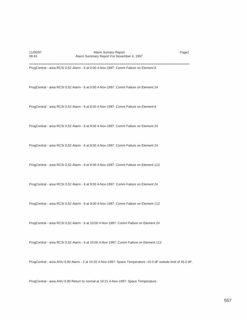
557
11/05/97 Alarm Sumary Report Page108:43 Alarm Summary Report For November 4, 1997
=====================================================================================ProgCentral - area RCSI 0,52 Alarm - 6 at 0:00 4-Nov-1997: Comm Failure on Element 8
ProgCentral - area RCSI 0,52 Alarm - 6 at 0:00 4-Nov-1997: Comm Failure on Element 24
ProgCentral - area RCSI 0,52 Alarm - 6 at 8:00 4-Nov-1997: Comm Failure on Element 8
ProgCentral - area RCSI 0,52 Alarm - 6 at 8:00 4-Nov-1997: Comm Failure on Element 24
ProgCentral - area RCSI 0,52 Alarm - 6 at 8:00 4-Nov-1997: Comm Failure on Element 24
ProgCentral - area RCSI 0,52 Alarm - 6 at 8:00 4-Nov-1997: Comm Failure on Element 112
ProgCentral - area RCSI 0,52 Alarm - 6 at 9:00 4-Nov-1997: Comm Failure on Element 24
ProgCentral - area RCSI 0,52 Alarm - 6 at 9:00 4-Nov-1997: Comm Failure on Element 112
ProgCentral - area RCSI 0,52 Alarm - 6 at 10:00 4-Nov-1997: Comm Failure on Element 24
ProgCentral - area RCSI 0,52 Alarm - 6 at 10:00 4-Nov-1997: Comm Failure on Element 112
ProgCentral - area AHU 0,90 Alarm - 2 at 10:20 4-Nov-1997: Space Temperature -10.0 dF outside limit of 45.0 dF.
ProgCentral - area AHU 0,90 Return to normal at 10:21 4-Nov-1997: Space Temperature.
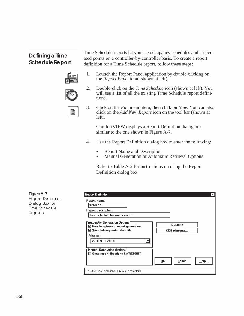
558
Defining a TimeSchedule Report
Figure A-7Report DefinitionDialog Box forTime ScheduleReports
Time Schedule reports let you see occupancy schedules and associ-ated points on a controller-by-controller basis. To create a reportdefinition for a Time Schedule report, follow these steps:
1. Launch the Report Panel application by double-clicking onthe Report Panel icon (shown at left).
2. Double-click on the Time Schedule icon (shown at left). Youwill see a list of all the existing Time Schedule report defini-tions.
3. Click on the File menu item, then click on New. You can alsoclick on the Add New Report icon on the tool bar (shown atleft).
ComfortVIEW displays a Report Definition dialog boxsimilar to the one shown in Figure A-7.
4. Use the Report Definition dialog box to enter the following:
• Report Name and Description• Manual Generation or Automatic Retrieval Options
Refer to Table A-2 for instructions on using the ReportDefinition dialog box.
559
5. Click on the CCN Elements button to display the CCN Ele-ments dialog box where you can select the CCN elementswhose schedules will be included in the report. Doubleclicking on an item moves it from one list to the other.
6. Click on OK to exit the dialog box and save changes, or clickon Cancel to exit the dialog box without saving changes.
ComfortVIEW re-displays the Time Schedule Report Defini-tion list.
The following page shows a sample Time Schedule report.Sample Report
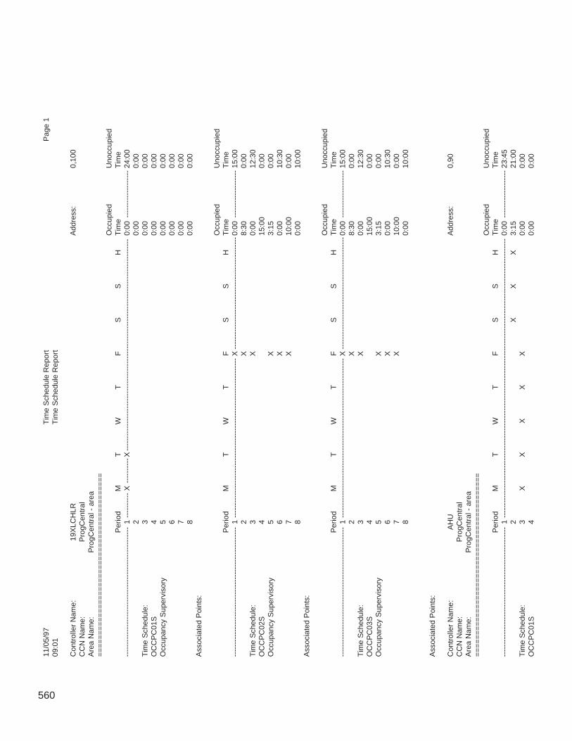
560
11/0
5/97
Tim
e S
ched
ule
Rep
ort
Pag
e 1
09:0
1T
ime
Sch
edul
e R
epor
t
Con
trol
ler
Nam
e:19
XLC
HLR
Add
ress
:0,
100
CC
N N
ame:
Pro
gCen
tral
Are
a N
ame:
Pro
gCen
tral
- a
rea
==
==
==
==
==
==
==
==
==
==
==
==
==
==
==
==
==
==
==
==
==
Occ
upie
dU
nocc
upie
dP
erio
dM
TW
TF
SS
HT
ime
Tim
e--
----
----
----
----
----
----
----
----
----
----
----
----
--1
----
----
--X
----
----
--X
----
----
----
----
----
----
----
----
----
----
----
----
----
----
----
----
----
----
----
----
----
-0:
00--
----
----
----
----
-24
:00
20:
000:
00T
ime
Sch
edul
e:3
0:00
0:00
OC
CP
C01
S4
0:00
0:00
Occ
upan
cy S
uper
viso
ry5
0:00
0:00
60:
000:
007
0:00
0:00
80:
000:
00A
ssoc
iate
d P
oint
s:
Occ
upie
dU
nocc
upie
dP
erio
dM
TW
TF
SS
HT
ime
Tim
e--
----
----
----
----
----
----
----
----
----
----
----
----
--1
----
----
----
----
----
----
----
----
----
----
----
----
----
----
----
----
X--
----
----
----
----
----
----
----
----
----
----
--- 0
:00
----
----
----
----
---
15:0
02
X8:
300:
00T
ime
Sch
edul
e:3
X0:
0012
:30
OC
CP
C02
S4
15:0
00:
00O
ccup
ancy
Sup
ervi
sory
5X
3:15
0:00
6X
0:00
10:3
07
X10
:00
0:00
80:
0010
:00
Ass
ocia
ted
Poi
nts:
Occ
upie
dU
nocc
upie
dP
erio
dM
TW
TF
SS
HT
ime
Tim
e--
----
----
----
----
----
----
----
----
----
----
----
----
--1
----
----
----
----
----
----
----
----
----
----
----
----
----
----
----
----
X--
----
----
----
----
----
----
----
----
----
----
--- 0
:00
----
----
----
----
---
15:0
02
X8:
300:
00T
ime
Sch
edul
e:3
X0:
0012
:30
OC
CP
C03
S4
15:0
00:
00O
ccup
ancy
Sup
ervi
sory
5X
3:15
0:00
6X
0:00
10:3
07
X10
:00
0:00
80:
0010
:00
Ass
ocia
ted
Poi
nts:
Con
trol
ler
Nam
e:A
HU
Add
ress
:0,
90C
CN
Nam
e:P
rogC
entr
alA
rea
Nam
e:P
rogC
entr
al -
are
a=
==
==
==
==
==
==
==
==
==
==
==
==
==
==
==
==
==
==
==
==
=O
ccup
ied
Uno
ccup
ied
Per
iod
MT
WT
FS
SH
Tim
eT
ime
----
----
----
----
----
----
----
----
----
----
----
----
----
1--
----
----
----
----
----
----
----
----
----
----
----
----
----
----
----
----
----
----
----
----
----
----
----
----
----
----
----
--0:
00--
----
----
----
----
-23
:45
2X
XX
3:15
21:0
0T
ime
Sch
edul
e:3
XX
XX
X0:
000:
00O
CC
PC
01S
40:
000:
00
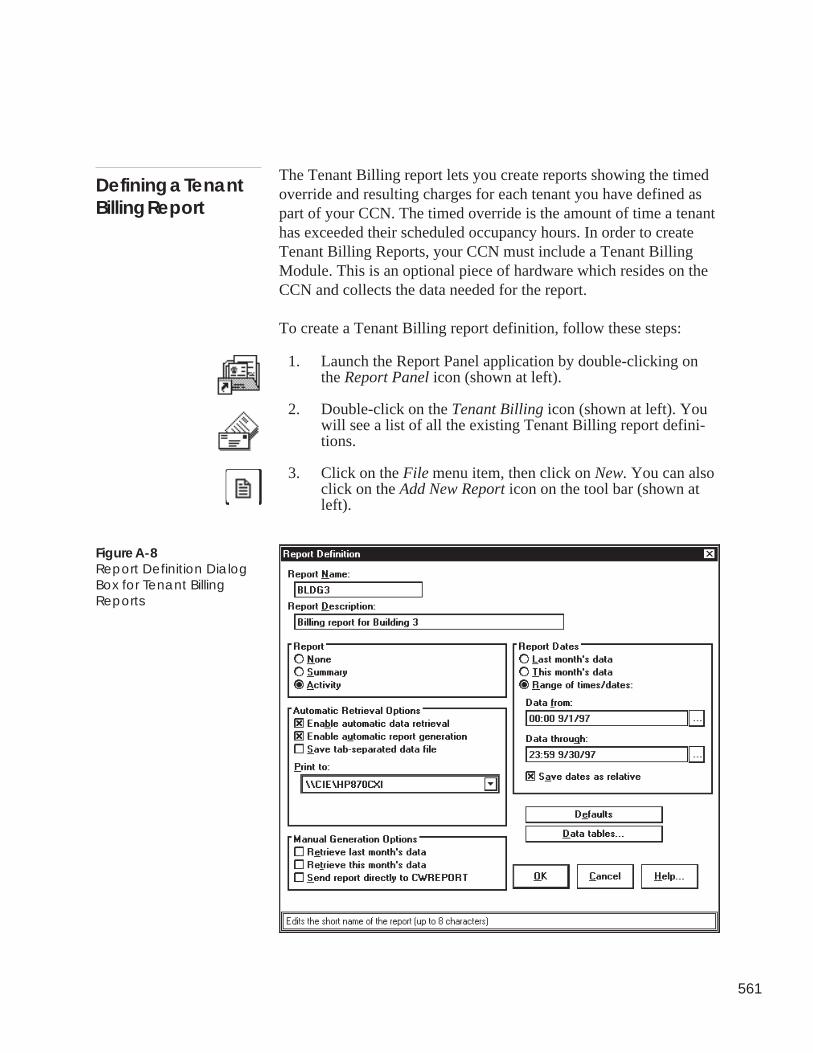
561
The Tenant Billing report lets you create reports showing the timedoverride and resulting charges for each tenant you have defined aspart of your CCN. The timed override is the amount of time a tenanthas exceeded their scheduled occupancy hours. In order to createTenant Billing Reports, your CCN must include a Tenant BillingModule. This is an optional piece of hardware which resides on theCCN and collects the data needed for the report.
To create a Tenant Billing report definition, follow these steps:
1. Launch the Report Panel application by double-clicking onthe Report Panel icon (shown at left).
2. Double-click on the Tenant Billing icon (shown at left). Youwill see a list of all the existing Tenant Billing report defini-tions.
3. Click on the File menu item, then click on New. You can alsoclick on the Add New Report icon on the tool bar (shown atleft).
Defining a TenantBilling Report
Figure A-8Report Definition DialogBox for Tenant BillingReports
562
ComfortVIEW displays a Report Definition dialog boxsimilar to the one shown in Figure A-8.
4. Use the Report Definition dialog box to enter the following:
• Report Name and Description• Report Type• Manual Generation or Automatic Retrieval Options• Report Dates
Refer to Table A-2 for instructions on using the ReportDefinition dialog box. Table A-9 describes additional reportdefinition features not described in Table A-2.
5. Click on the Data Tables button to display the Report DataTables dialog box where you can select the data tables thatwill be included in the report. Generally, each customer's datais stored in its own data table, so the Data Tables button letsyou select which customers to include in the report. Doubleclicking on an item moves it from one list to the other.
6. Click on OK to exit the dialog box and save changes, or clickon Cancel to exit the dialog box without saving changes.
ComfortVIEW re-displays the Alarm Summary ReportDefinition list.
To learn more about defining tenants and tenant billing, see the TenantBilling Option Overview and Configuration Manual (808-730).
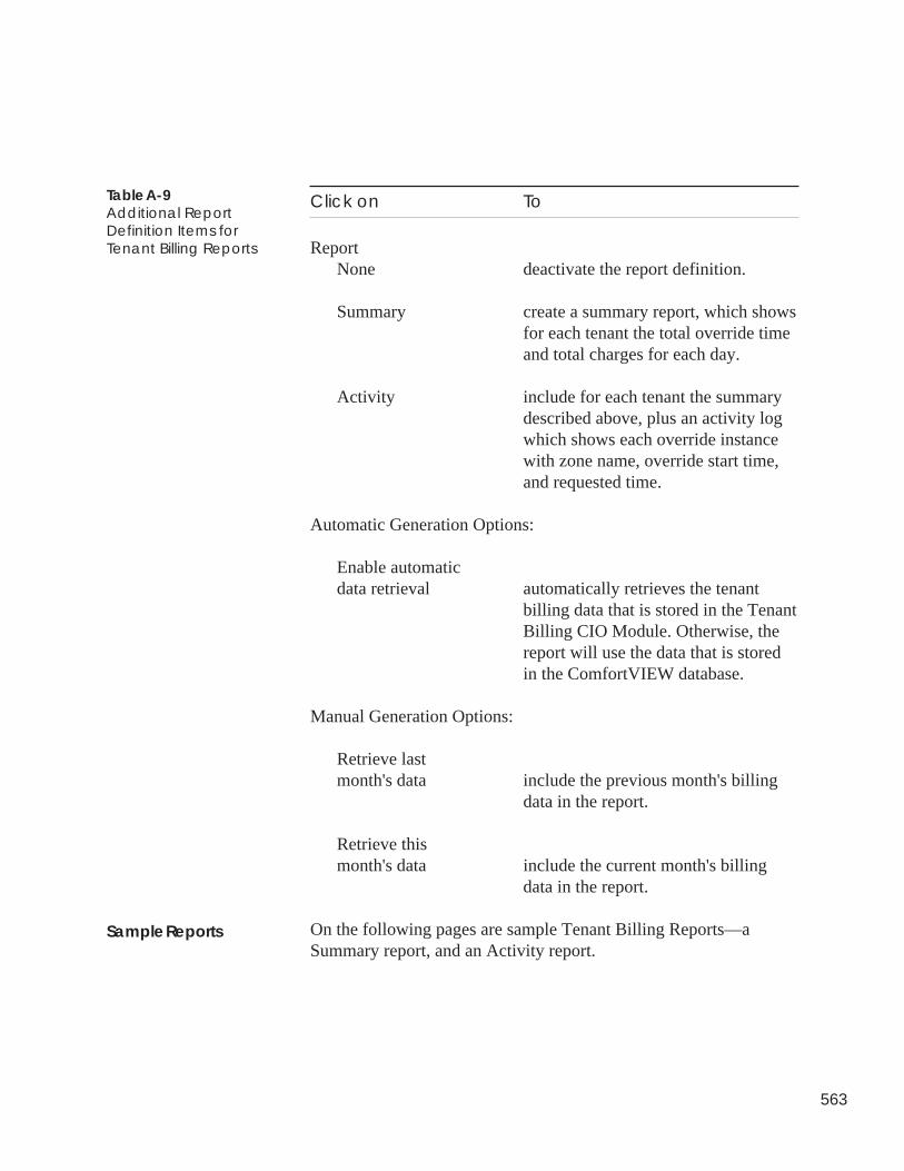
563
Click on To
ReportNone deactivate the report definition.
Summary create a summary report, which showsfor each tenant the total override timeand total charges for each day.
Activity include for each tenant the summarydescribed above, plus an activity logwhich shows each override instancewith zone name, override start time,and requested time.
Automatic Generation Options:
Enable automaticdata retrieval automatically retrieves the tenant
billing data that is stored in the TenantBilling CIO Module. Otherwise, thereport will use the data that is storedin the ComfortVIEW database.
Manual Generation Options:
Retrieve lastmonth's data include the previous month's billing
data in the report.
Retrieve thismonth's data include the current month's billing
data in the report.
On the following pages are sample Tenant Billing Reports—aSummary report, and an Activity report.
Table A-9Additional ReportDefinition Items forTenant Billing Reports
Sample Reports
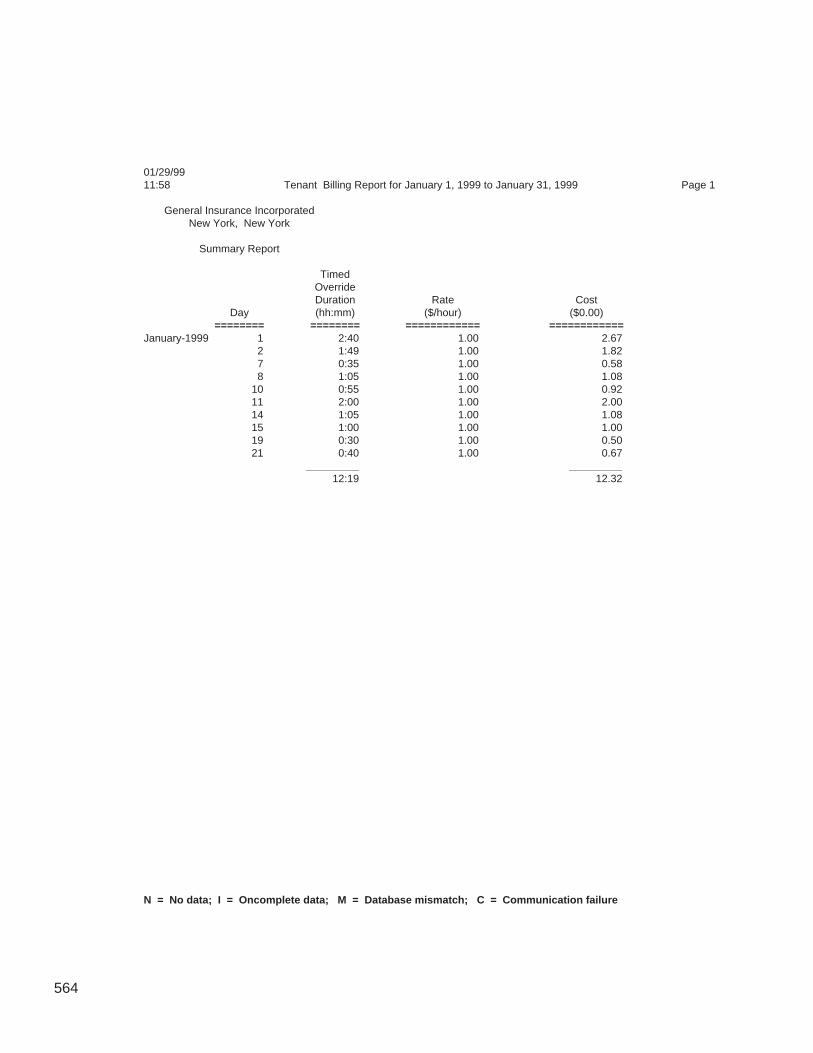
564
01/29/9911:58 Tenant Billing Report for January 1, 1999 to January 31, 1999 Page 1
General Insurance IncorporatedNew York, New York
Summary Report
TimedOverrideDuration Rate Cost
Day (hh:mm) ($/hour) ($0.00)======== ======== ============ ============
January-1999 1 2:40 1.00 2.672 1:49 1.00 1.827 0:35 1.00 0.588 1:05 1.00 1.08
10 0:55 1.00 0.9211 2:00 1.00 2.0014 1:05 1.00 1.0815 1:00 1.00 1.0019 0:30 1.00 0.5021 0:40 1.00 0.67
_________ _________12:19 12.32
N = No data; I = Oncomplete data; M = Database mismatch; C = Communication failure
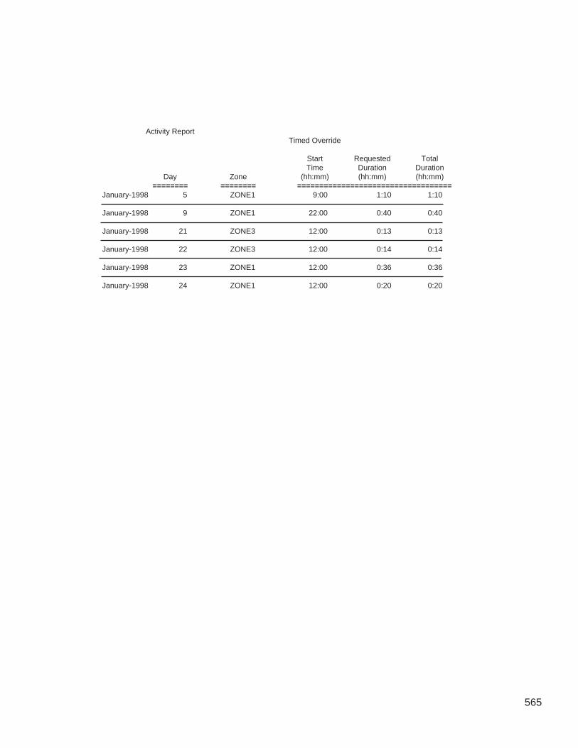
565
Activity ReportTimed Override
Start Requested TotalTime Duration Duration
Day Zone (hh:mm) (hh:mm) (hh:mm)======== ======== ===================================
January-1998 5 ZONE1 9:00 1:10 1:10
January-1998 9 ZONE1 22:00 0:40 0:40
January-1998 21 ZONE3 12:00 0:13 0:13
January-1998 22 ZONE3 12:00 0:14 0:14
January-1998 23 ZONE1 12:00 0:36 0:36
January-1998 24 ZONE1 12:00 0:20 0:20

566
567
Appendix B —CWACCESS.DLL
ComfortVIEW includes a dynamic-link library (DLL) which allowsthird-party programs to access CCN system elements, central timeschedules, and occupancy and setpoint schedules. It also lets thoseprograms use Carrier's Autodial Gateway and Telink products toconnect to remote CCNs. This new DLL, CWACCESS.DLL, isinstalled in the \CVIEW\Apps directory at the same timeComfortVIEW is installed. The DLL is designed so that applicationswhich use it can work independently of ComfortVIEW. You do notneed to be logged in to ComfortVIEW to use the DLL, nor doesComfortVIEW need to be installed on the machine from which youare accessing the DLL's functions. ComfortVIEW must however, beinstalled and running on a ComfortVIEW server computer that islocated on the same network as the computer from which you areaccessing this DLL.
The DLL provides the following functions:
CW_InitLibCW_GetErrorBufferCW_CloseLibCW_OpenOccupancyTableCW_CloseOccupancyTableCW_ReadPeriodCW_WritePeriodCW_OpenSetPointTableCW_CloseSetPointTableCW_ReadSetPointCW_WriteSetPointCW_ConnectToRemoteCCNCW_DisconnectFromRemoteCCN
The following sections describe each of these functions, includingreturn values and parameters, C++ prototypes from the DLL, andsample Visual Basic declarations and function calls.
Note that for those functions which return string values to theirparameters, the parameter variable must be initialized with somevalue (not just declared or dimensioned) before the function iscalled. You must use the CW_InitLib function to establish theconnection to the ComfortVIEW server before using any of theother functions. For all functions (except for CW_CloseLib andCW_GetErrorBuffer), the result should be checked for an error; usethe CW_GetErrorBuffer function to display the actual error.
Overview
568
int CW_InitLib(char *Server)
This function initializes the connection to the ComfortVIEW server.This connection must be established before any tables or setpointscan be read or written to.
Parameters–Server The name of the ComfortVIEW Server
Return Value–The function returns 0 if there is no error; any other valueindicates an error. (See the description of CW_GetError-Buffer() for more information on CWACCESS errors.)
Sample Declaration–Public Declare Function CW_InitLib Lib“CWACCESS.DLL” (ByVal Server As String) As Integer
Example–Server = “ \\ProgCentral2”Result = CW_InitLib(Server)
int CW_GetErrorBuffer(char *ErrBuf)
This function retrieves any error messages that are produced by anyCWACCESS function. It will retrieve up to 255 characters from theError Queue, and will also retrieve multiple error messages.
Parameters–ErrBuf A string of up to 255 characters which stores an
error message
Return Value–The value 0 indicates that there are still error messages in theerror buffer; a positive value indicates there are no moreerror messages.
CW_InitLib()
CW_GetErrorBuffer()
569
Sample Declaration–Public Declare Function CW_GetErrorBuffer Lib“CWACCESS.DLL” (ByVal ErrBuf As String) As Integer
Example–ErrBuf = String(255, 0)ErrResult = CW_GetErrorBuffer(ErrBuf)While ErrResult = 0
MsgBox “Error Detected = “ & ErrBufErrResult = CW_GetErrorBuffer(ErrBuf)
Wend
In the above example, CW_GetErrorBuffer is called in a While loopto ensure that all error messages will be displayed.
void CW_CloseLib()
This function terminates the connection to the ComfortVIEWserver.
Parameters–None
Return Value–None
Sample Declaration–Public Declare Sub CW_CloseLib Lib “CWACCESS.DLL” ()
Example–Call CW_CloseLib
CW_CloseLib()
570
int CW_OpenOccupancyTable(unsigned long CCNNumber, un-signed short Bus, unsigned short Controller, unsigned shortOccupancyTableNumber, char * OccupancyTableName, unsignedshort *TableID)
This function opens the time schedule for the controller which isspecified by the function’s arguments. The table to be opened can bespecified by either its name or number. If the value of Occupancy-TableNumber = 0, the function will use the string stored inOccupancyTableName to identify the desired table. If Occupancy-TableNumber contains a valid table number, it will open the tableand return its name in OccupancyTableName. When a table hasbeen successfully opened, a system-generated integer is returned toTableId. This number is then used by the CW_CloseOccupancy-Table, CW_WritePeriod and CW_ReadPeriod functions to identifythe appropriate table.
This function can also be used to open the Central Time Schedule.To open the Central Time Schedule, use the following arguments:CCNNumber, Bus, and Controller must be 0, and the Occupancy-TableName must be a name of the Central Time Schedule.
Parameters–CCNNumber The CCN number of the controller
whose occupancy table you wantto open
Bus The number of the CCN bus thecontroller is on
Controller The ID number of the controllerOccupancyTableNumber The controller’s occupancy table
numberOccupancyTableName The controller’s occupancy table
nameTableId Returns the table id of the opened
table
Return Value–The function returns 0 if there is no error; any other valueindicates an error. (See the description of CW_GetError-Buffer() for more information on CWACCESS errors.)
CW_OpenOccupancyTable()
571
Sample Declaration–Public Declare Function CW_OpenOccupancyTable Lib“CWACCESS.DLL” (ByVal CCNNumber As Long,ByVal Bus As Integer, ByVal Controller As Integer, ByValOccupancyTableNumber As Integer, ByValOccupancyTableName As String, TableId As Integer) AsInteger
Example–CCNNumber = 1Bus = 0Controller = 10OccupancyTableNumber = 1OccupancyTableName = String(255, 0)TableId = 0Result = CW_OpenOccupancyTable(CCNNumber, Bus,Controller, OccupancyTableNumber,OccupancyTableName, TableId)
int CW_CloseOccupancyTable (unsigned short TableId, intSaveflag)
This function closes the occupancy table specified by TableId. Youcan can also set SaveFlag to save any changes made to the tablewith the CW_WritePeriod function. The results of the functionCW_WritePeriod will not be stored in the database until theCW_CloseOccupancyTable function is called with a non-zero valuefor Saveflag.
If the CW_CloseOccupancyTable function fails, it may fail atdifferent stages of completion. The function GetErrorBuffer willdisplay the extent of the error. If the error indicates that a table issuccessfully downloaded into the ComfortVIEW database but notdownloaded into the controller, the table will not be downloadedinto the controller at a later time automatically by ComfortVIEW.
CW_CloseOccupancyTable()
572
Parameters–TableId This is the TableId obtained from the
CW_OpenOccupancyTable Function.Saveflag If this flag is set to a non-zero value the table will
be saved to the database and downloaded to thecontroller. If it is set to zero any changes will notbe saved
Return Value–The function returns 0 if there is no error; any other valueindicates an error. (See the description of CW_GetError-Buffer() for more information on CWACCESS errors.)
Sample Declaration–Public Declare Function CW_CloseOccupancyTable Lib“CWACCESS.DLL” (ByVal TableId As Integer, ByValSaveflag As Integer) As Integer
Eaxmple–Saveflag = 1Result = CW_CloseOccupancyTable(TableId, Saveflag)
int CW_ReadPeriod (unsigned short TableId, unsigned shortPeriodNumber, unsigned short *DOWFlags, unsigned short*OccupiedStartHour, unsigned short *OccupiedStartMinute, un-signed short *OccupiedEndHour, unsigned short*OccupiedEndMinute)
This function reads an Occupancy Period based upon the TableIdand the PeriodNumber. The period is specified as the days of theweek, and a start and end time. The table to be read must have beenopened with the CW_OpenOccupancyTable function prior to callingthis function. When the table is opened, the CW_OpenOccupancy-Table function returns the TableId value which is used by theCW_ReadPeriod function to identify the proper table.
CW_ReadPeriod()
573
Parameters–TableId This value is supplied by the
CW_OpenOccupancyTable functionPeriodNumber The period number to readDOWFlags Returns a packed byte representing
the days of the week and holidays inthe following manner: MTWTFSSH
OccupiedStartHour Returns the start hour of period 0–24OccupiedStartMinute Returns the start Minute of period
0–59OccupiedEndHour Returns the end hour of period 0–24OccupiedEndMinute Returns the end Minute of period
0–59
Return Value–The function returns 0 if there is no error; any other valueindicates an error. (See the description of CW_GetError-Buffer() for more information on CWACCESS errors.)
Sample Declaration–Public Declare Function CW_ReadPeriod Lib“CWACCESS.DLL” (ByVal TableId As Integer, ByValPeriodNumber As Integer, DOWFlags As Integer,OccupiedStartHour As Integer, OccupiedStartMinute AsInteger, OccupiedEndHour As Integer, OccupiedEndMinuteAs Integer) As Integer
Example–PeriodNumber = 1DOWFlags = 0OccupiedStartHour = 0OccupiedStartMinute = 0OccupiedEndHour = 0OccupiedEndMinute = 0Result = CW_ReadPeriod(TableId, PeriodNumber,DOWFlags, OccupiedStartHour, OccupiedStartMinute,OccupiedEndHour, OccupiedEndMinute)
574
The DOWFlags are stored as a packed byte. The sample code belowshows a way to translate the data to a more usable form.CheckDay0–CheckDay8 are eight variables which correspond to theMTWTFSSH of the DOWFlags; 1 indicates that the day is in theperiod, 0 indicates that it is not.
DOWMask(8) As IntegerDOWMask(0) = 128DOWMask(1) = 64DOWMask(2) = 32DOWMask(3) = 16DOWMask(4) = 8DOWMask(5) = 4DOWMask(6) = 2DOWMask(7) = 1
For key = 0 To 7DayLoop = “CheckDay” & keyIf (DOWFlags And DOWMask(key)) Then
Me(DayLoop) = 1Else
Me(DayLoop) = 0End If
Next key
The Me(DayLoop) expression is used to access the variable name,which is stored as a string in DayLoop and is a member of thecurrent Microsoft Access Form. This could also be accomplished inVisual Basic by storing the values in an array.
int CW_WritePeriod(unsigned short TableId, unsigned shortPeriodNumber, unsigned short DOWFlags, unsigned shortOccupiedStartHour, unsigned short OccupiedStartMinute, unsignedshort OccupiedEndHour, unsigned short OccupiedEndMinute)
This function writes a period specification to the table specified inTableId. The table to be written to must have been opened with theCW_OpenOccupancyTable function prior to calling this function.When the table is opened with this function, it returns the TableId
CW_WritePeriod()

575
value which is used by the CW_WritePeriod function to identify theproper table.
Note that the new period is not saved to the database until the tableis closed with the CW_CloseOccupancyTable function and a non-zero SaveFlag. However, if you read this table before it is closed,you will receive the new data.
Parameters–TableId This value is supplied by the
CW_OpenOccupancyTable functionPeriodNumber The period number to readDOWFlags Returns a packed byte representing
the days of the week and holidays inthe following manner: MTWTFSSH
OccupiedStartHour Returns the start hour of period 0–24OccupiedStartMinute Returns the start Minute of period
0–59OccupiedEndHour Returns the end hour of period 0–24OccupiedEndMinute Returns the end Minute of period
0–59
Return Value–The function returns 0 if there is no error; any other valueindicates an error. (See the description of CW_GetError-Buffer() for more information on CWACCESS errors.)
Sample Declaration–Public Declare Function CW_WritePeriod Lib“CWACCESS.DLL” (ByVal TableId As Integer, ByValPeriodNumber As Integer, ByVal DOWFlags As Integer,ByVal OccupiedStartHour As Integer, ByValOccupiedStartMinute As Integer, ByVal OccupiedEndHourAs Integer, ByVal OccupiedEndMinute As Integer) AsInteger
576
Example–TableId = TableIdPeriodNumber = 1OccupiedStartHour = 5OccupiedStartMinute = 30OccupiedEndHour = 18OccupiedEndMinute = 15Result = CW_WritePeriod(TableId, PeriodNumber,DOWFlags, OccupiedStartHour,OccupiedStartMinute, OccupiedEndHour,OccupiedEndMinute)
The DOWFlags are stored as a packed byte. The sample code belowshows a way to translate the data to a more usable form.CheckDay0–CheckDay8 are eight variables which correspond to theMTWTFSSH of the DOWFlags; 1 indicates that the day is in theperiod, 0 indicates that it is not.
DOWMask(8) As IntegerDOWMask(0) = 128DOWMask(1) = 64DOWMask(2) = 32DOWMask(3) = 16DOWMask(4) = 8DOWMask(5) = 4DOWMask(6) = 2DOWMask(7) = 1
DOWFlags = 0For key = 0 To 7
DayLoop = “CheckDay” & keyIf (Me(DayLoop) <> 0) Then
DOWFlags = DOWFlags Or DOWMask(key)End If
Next key
577
int CW_OpenSetPointTable (unsigned long CCNNumber, unsignedshort Bus, unsigned short Controller, char * SetPointTableName,unsigned short *SetPointTableId, unsigned short *SetPointCount)
This function opens the setpoint table which is identified by thefunction’s arguments: CCN number, bus number, controller elementnumber, and table name. When a setpoint table has been success-fully opened, a system-generated integer is returned to SetPoint-TableId. This number is then used by the CW_CloseSetPointTable,CW_WriteSetPoint and CW_ReadSetPoint functions to identify theappropriate table.
Parameters–CCNNumber The CCN number of the controller
whose setpoint table you want toopen
Bus The number of the CCN bus thecontroller is on
Controller The ID number of the controllerSetPointTableName The controller’s setpoint table nameSetPointTableId Returns the table id of the opened
tableSetpointCount Returns the number of points in the
setpoint table
Return Value–The function returns 0 if there is no error; any other valueindicates an error. (See the description of CW_GetError-Buffer() for more information on CWACCESS errors.)
Sample Declaration–Public Declare Function CW_OpenSetPointTable Lib“CWACCESS.DLL” (ByVal CCNNumber As Long, ByValBus As Integer, ByVal Controller As Integer, ByValSetPointTableName As String, SetPointTableId As Integer,SetPointCount As Integer) As Integer
CW_OpenSetPointTable()
578
Example–CCNNumber = 1Bus = 0Controller = 10SetPointTableName = String(255, 0)SetPointTableName = “SS01”SetPointTableId = 0SetPointCount = 0Result = CW_OpenSetPointTable(CCNNumber, Bus,Controller, SetPointTableName, SetPointTableId,SetPointCount)
int CW_CloseSetPointTable (unsigned short SetPointTableId, intSaveflag)
This function closes the setpoint table specified by SetPointTableId.You can can also set SaveFlag to save any changes made to the tablewith the CW_WriteSetPoint function. The results of the functionCW_WriteSetPoint will not be stored in the database until theCW_CloseSetPointTable function is called with a non-zero valuefor Saveflag.
If the CW_CloseSetPointTable function fails, it may fail at differentstages of completion. The function GetErrorBuffer will display theextent of the error. If the error indicates that a table is successfullydownloaded into the ComfortVIEW database but not downloadedinto the controller, the table will not be downloaded into the control-ler at a later time automatically by ComfortVIEW.
Parameters–SetPointTableId This is the SetPointTableId obtained from
the CW_OpenSetPointTable Function.Saveflag If this flag is set to a non-zero value the
table will be saved to the database anddownloaded to the controller. If it is set tozero any changes will not be saved
CW_CloseSetPointTable()
579
Return Value–The function returns 0 if there is no error; any other valueindicates an error. (See the description of CW_GetError-Buffer() for more information on CWACCESS errors.)
Sample Declaration–Public Declare Function CW_CloseSetPointTable Lib“CWACCESS.DLL” (ByVal SetPointTableId As Integer,ByVal Saveflag As Integer) As Integer
Example–Saveflag = 1Result = CW_CloseSetPointTable(SetPointTableId,Saveflag)
int CW_ReadSetPoint(unsigned short SetPointTableId, unsignedshort PointNumber, char *Description, char *Name, double *Value,char *Units, double *HighLimit, double *LowLimit, char *Notes)
This function reads the setpoint information for the setpoint speci-fied by the function’s arguments.
Parameters –SetPointTableId This is the SetPointTableId returned by
CW_OpenSetPointTable.Point Number The number of the point to read.Description This string returns the description.Name This string returns the point’s name.Value Returns the value of the point.Units This string returns the units of the point’s
value and limits.HighLimit Returns the maximum value the point can
hold.LowLimit Returns the minimum value the point can
hold.Notes This string returns the point’s notes.
CW_ReadSetPoint()
580
Return Value–The function returns 0 if there is no error; any other valueindicates an error. (See the description of CW_GetError-Buffer() for more information on CWACCESS errors.)
Sample Declaration–Public Declare Function CW_ReadSetPoint Lib“CWACCESS.DLL” (ByVal SetPointTableId As Integer,ByVal PointNumber As Integer, ByVal Description AsString, ByVal Name As String, Value As Double, ByValUnits As String, HighLimit As Double, LowLimit AsDouble, ByVal Notes As String) As Integer
Example–PointNumber = 1Name = String(15, 0)Units = String(10,0)Value = 0HighLimit = 0LowLimit = 0Description = String(255,0)Notes = String(255,0)Result = CW_ReadSetPoint(SetPointTableId, PointNumber,Description, Name, Value, Units, HighLimit, LowLimit,Notes)
int CW_WriteSetPoint(unsigned short SetPointTableId, unsignedshort PointNumber, char *Description, double Value)
This function writes a value to the table and setpoint specified bythe function's arguments. This information is not saved to the data-base until the table is closed by CW_CloseSetPointTable functionwith a non-zero SaveFlag; however, if you read this table before it isclosed, you will receive the new data. Value is the only field thatcan be changed in a setpoint table. If the value of PointNumber = 0,the function will use the string stored in Description to identify thedesired point.
CW_WriteSetPoint()
581
Parameters–SetPointTableId This is the SetPointTableId returned by
the CW_OpenSetPointTable functionPointNumber The number of the point to write to.Description The description of the point to write to.
If PointNumber < > 0, this parameter canbe left blank.
Value The value to set the point to.
Return Value–The function returns 0 if there is no error; any other valueindicates an error. (See the description of CW_GetError-Buffer() for more information on CWACCESS errors.)
Sample Declaration–Public Declare Function CW_WriteSetPoint Lib“CWACCESS.DLL” (ByVal SetPointTableId As Integer,ByVal PointNumber As Integer, ByVal Description AsString, ByVal Value As Double) As Integer
Example–PointNumber = 1Value = 100.4Description = String(255,0)Result = CW_WriteSetPoint(SetPointTableId, PointNumber,Description, Value)
int CW_ConnectToRemoteCCN(char *RemoteCCNName)
This function establishes a connection to a remote CCN.
Parameters–RemoteCCNName The name of the remote CCN to connect
to
Return Value–The function returns 0 if the connection was establishedsuccessfully; any other value indicates an error. (See thedescription of CW_GetErrorBuffer() for more informationon CWACCESS errors.)
CW_ConnectToRemoteCCN()
582
Sample Declaration–Public Declare Function CW_ConnectToRemoteCCN Lib“CWACCESS.DLL” (ByVal CCNName As String) AsInteger
Example-Rname = "RemoteSite"Result = CW_ConnectToRemoteCCN(Rname)
int CW_DisconnectFromRemoteCCN(char *RemoteCCNName)
This function terminates the connection to a remote CCN.
Parameters-RemoteCCNName The name of the remote CCN to
disconnect from.
Return Value-The function returns 0 if the connection was terminatedsuccessfully; any other value indicates an error. (See thedescription of CW_GetErrorBuffer() for more informationon CWACCESS errors.)
Sample Declaration-Public Declare Function CW_DisconnectFromRemoteCCNLib "CWACCESS.DLL" (ByVal CCNName As String) AsInteger
Example-Rname = "RemoteSite"Result = CW_DisconnectFromRemoteCCN(Rname)
CW_DisconnectFromRemoteCCN()

Index

Alarm Manager
583
Index
AAccess Levels
assigning to operators 401creating 395defining 392deleting 395functions 394modifying 395
AccessingAlarms 328Carrier Network Manager 32Global Function Manager 517Report Panel 451Setup 385WorkSPACE Manager 216
Acknowledgingalarms 341
Addingaccess levels 395alarm printer 422areas 54Consumable Tables 123controllers 60custom alarm messages 354data box 275History Tables 124LAN Workstation 419link area 275new CCN 39operators 386, 389option tables 120port locations 422remote sites 209report definition 457Runtime Tables 123system elements 60trends 279ViewSPACEs 245
Adjustingcolumns 76
Alarmaccessing 328acknowledging 341assigning a WorkSPACE 361attaching a WorkSPACE 360attaching custom messages 353attaching operator note 343audio configuration 353, 415beeping 326critical 327, 408, 409definition 324deleting 349disabling 346enabling 346Export command 374export to clipboard com-
mand 376filters 408, 411, 413flashing icon 326, 328
icons 332icons, pop-up window 329indication 325indication preferences 327levels 335linking messages to other applica-
tions 178menu commands 374message, contents 334message, example 333message format 333modifying alarm WorkSPACE 363pop-up window 326, 328, 329pop-up window, example 328printing automatically 352purging 432selecting 340specifying indication prefer-
ences 405specifying printers 417specifying your own indication
preference 406, 407suppressing 346toolbar, explanation 331viewing new and unacknowl-
edged 328viewing suppressed 347wildcards 370
Alarm Acknowledger 51Alarm History Tables
displaying 81Alarm List
color 371example 330font 336printing 350sorting 338status bar 335updating 337viewing 330
Alertdefinition 324
Analog Statesdefining 425
Animated Data Boxdefinition 214
Animated Graphicspecifications 299
Archivingtrend data to file 232
Area(s)adding 54definition 54deleting 57displaying a list 33displaying a list, short-cut 34modifying name 55
AssigningWorkSPACEs to alarms 361
Attachingalarm operator note 343
584
custom alarm messages 353operator note 343WorkSPACEs to incoming
alarms 364Audio Configuration
alarms 353, 415Autodial Gateways
assigning operations 47, 166connecting to remote CCNs 169
AutoingMaintenance Tables 94, 517points 94, 517status display or maintenance
table values 517Status Display Tables 94, 517
Automatic Retrieval Optionsreport definition 461, 542, 563
BBasic Bus Scan 82, 84, 89Beeping sound
alarm indication 326BEST++
accessing 537configuration and maintenance
tables 161Bookmark
definition 214jumping to WorkSPACEs 224placing 224removing 224run mode 224
Broadcastingpoint data 522time of day, date, day of week,
holiday status 118, 527Bus Scan 82
CCarrier Network Manager
accessing 32commands 179Font Command 193Gateways Commands 192launching 32NDS - Update Poll Command 191overview 32Print Setup Command 180toolbar 36
CCN Optionsalternate method for adding/
modifying tables 120deleting tables 127displaying 125displaying/configuring 120modifying 125modifying table descriptions 126
CCN(s)accessing database only 44accessing local workstations 45accessing remote workstations 45adding 39adding direct local connec-
tion 40adding modem connection 41adding remote-gateway 41deleting 56displaying the list 33exporting 433importing 437modifying access parameter 49modifying name 49modifying number 49number, purpose 43
Cellcopying/pasting data 103definition 74, 80
Central Time Schedulescreating 527
Clientdefinition 201
CloningWorkSPACEs 246, 261, 283, 301
Colorsalarm list 371
Columnsadjusting 76hiding 76showing 76
Comfort Controller ReferenceJumps 81
ComfortVIEWcommand menu conventions 22help 25logging out 10related documentation 6window elements 18
ComfortVIEW Databaseoff-line preparation 63uploading to 63
ComfortVIEW databaseadding a controller 60
CommandsAlarm Menu 374Carrier Network Manager 179keyboard selection 23menu convention 22mouse selection 23Report Definition List 503Report Panel 501Setup Menu 443WorkSPACE Manager 301
Configuration Datadownloading from ComfortVIEW to
controllers 115exporting 163uploading from controllers to
ComfortVIEW 116
verifying 114Configuration Tables
copying 63displaying 78, 81displaying Setpoint and Occu-
pancy graphically 80, 198, 320displaying UT203 FID 80example 79format 80importing from 63modifying decision descrip-
tions 103, 106modifying values 97multiple instances of data 80types 79, 161use 78, 81viewing 78, 81
ConfiguringCCN Options 120Comfort Controllers 132UT203 FIDs 128, 132
Connectingremote CCNs 169, 290remote server workstation 205
Consumable Reportcontents 451Daily, sample 510defaults 466explanation 475Monthly, sample 511required conditions for 482Yearly, sample 512
Consumable Tablesconfiguring in CCN Options 120configuring in Comfort Control-
lers 146Controller Configuration Data
exporting 163Controller Database Report 171
printing 172Controller List
displaying 34modifying table names/descrip-
tions 104sorting 59
Controller List Reportprinting 172
Controller List Windowdisplaying 58example 58, 71
Controllersadding 60definition 30, 58deleting 69modifying description 66modifying name 66modifying sort key 66
Copyingconfiguration data by drag and
drop 108, 110
585
configuration data with Copycommand 109, 111
configuration table values 103configuration tables 63individual tables 110Maintenance Table Values 96report definition 458Status Display Table Values 96
Copying and Moving ControllerConfiguration Data 107
Creatingaccess levels 395report definition 457report text files 494tabular ViewSPACE dis-
plays 277, 318trends 279ViewSPACEs 245, 255, 256WorkSPACEs 245
Critical Alarmenabling visual indication of 409indication 327
Critical Alarm Threshold 408Custom Alarm Messages
assigning to incoming alarms 353Custom Engineering Units
analog states 425defining 425discrete states 425
Customizingpoint displays 75
CWREPORT printer option. 485
DData Box
adding 275animated, definition 214cascading 318definition 214deleting 274modifying 263modifying location 273modifying parameters 273modifying size 273viewing description 235viewing point name and descrip-
tion 235Data Box Frame
guidelines for creation 298Data Point
parameters/values 235report definition 466, 470selection 267submaster 238
Data Rangereport defini-
tion 460, 467, 468, 469, 541Data Retention Period 428
Data Retrievalretries 428specifying time 428
Data StatusReport Panel 484
Datemodifying/sending 118
Day of Weekmodifying/sending 118
DDErequired conditions 77, 175sharing ComfortVIEW data with
other applica-tions 77, 175, 241, 244
Decision Descriptionsgreen coloring 98modifying 103, 106
DedicatingAutodial Gateways 166
DefaultsConsumable/Runtime Reports 466History Report 465
Definingalarm printer names/port loca-
tions 422analog states 425custom engineering units 425discrete states 425LAN workstation 419System Access Levels 392
Delete a ViewSPACE 278Deleting
access levels 395alarm printers 423alarms 349areas 57CCNs 56controllers 69custom alarm messages 354data box 274LAN Workstations 420link area 274operators 390option tables 127port locations 423remote sites 212report definition 479trend 288WorkSPACEs 253
Deleting/Removing ViewSPACEs 278Descriptions
modifying 104modifying in option tables 126
Design Modedefinition 214printing trend window 295printing ViewSPACE 295
Detailed Bus Scan 82, 84, 90Device Config Report 171Dialog Box
explanation 24sample 6
Disconnectingremote CCN 170, 292remote server workstation 208
DisplayingConfiguration Tables 78, 81Controller List Window 58maintenance tables 70option configuration tables 125point IDs 77point range, Y-axis 229report definition list 454status bar 454status display tables 70trend, run mode 226, 283trend value 229trends 225UT203 FID configuration tables 80ViewSPACE 233WorkSPACEs 361WorkSPACEs associated with
alarms 360Downloading
configuration data fromComfortVIEW to controller 115
to the Comfort Controller 158Drag and Drop 98
copying configurationdata 108, 110
example 99Drop Down List
WorkSPACE Manager 221Dynamic Data Exchange
ComfortVIEW data 77, 175required conditions 77, 175
EEditing
report data 494Exit the Tabular Display and Re-Size
Databoxes 278Exporting
a CCN's database 433command, Alarm Manager 374Controller Configuration Data 163
Exporting to Clipboardcommand, Alarm Manager 376
FFast User Switching 7FIDs
configuring 128, 132uploading 117
Filtersalarm 408, 411, 413
Font
586
alarms, changing 336Carrier Network Manager 193changing in the Carrier Network
Manager 38report definition, changing 480Report Definition List 507
Forceclearing (autoing) 94, 517definition 30Maintenance Tables 92, 517messages 75notes 95Status Display Tables 92, 517
Forcingautomatically 517status display or maintenance
table values 92, 517WorkSPACE values 241, 243
Frame Family 269Function
definition 30
GGateways
assigning operations 166Carrier Network Manager 192connecting to remote CCNs 169
Generatingreports 481reports, automatically 484reports, manually 483, 484
Generation Optionsreport definition 464
Global Function Manageraccessing 517commands 534launching 517
Global Parameterssetup 430specifying 428
Graphic Backgroundcreating 256specifications 255
Green Shadingon configuration decisions 98
HHelp
usage 25Hiding
columns 76History Report
contents 451defaults 465explanation 473required conditions for 482sample 516
History Tables
adding 124configuring in CCN Options 120
Holiday Statusmodifying/sending 118specifying 527
IIcons
alarm 332alarm indicator window 329Carrier Network Manager tool-
bar 36flashing alarm 326, 328Report Definition List 456Report Panel 452System Overview Window 35
Importinga CCN's database 437configuration tables 63data to Consumable or Runtime
data files 495
JJumping
bookmarked WorkSPACE 224from Comfort Controller status
display tables 70from configuration
tables 81, 155, 156from status display and mainte-
nance tables 70from trends 231
KKeyboard
functions 15selecting commands 23usage 14
LLAN Workstation
adding 419defining 419deleting 420setup 420, 421
Launchingareas, short-cut 34Carrier Network Manager 32CNM, short-cut 34Report Panel 452Setup 385WorkSPACE Manager 217
Link Areaadding 275deleting 274
modifying 270, 275showing all 316
List Entry 153to configure Comfort Control-
lers 153Locking
a ViewSPACE 260Logging In
automatic 431Windows 6
Logging OutComfortVIEW 10Windows NT 7
MMagenta Shading
on point names 70, 81, 153, 156Maintenance Tables
autoing 94displaying 70example 73format 74linking data to other PC applica-
tions 78, 81messages 74modifying (forcing) values 92modifying point descriptions 96viewing 70
Managingreport files 497
Manual Generation Optionsreport definition 464
Master and Override Time Schedulescreating 527
Menuconventions 22
Menu BarWorkSPACE Manager 219
Menu SummaryAlarms 374Carrier Network Manager 179Report Definition List 503Report Panel 501Setup 443WorkSPACE Manager 301
Messagesaccess denied 206alarm, contents 334alarm, example 333alarm, format 333alarm precedence 358custom alarm 353force 75Maintenance Tables 74Status Display Table 74
Modedesign, definition 214design, printing trend window 295
587
design, printing ViewSPACE 295design vs. run 216run, displaying trend 283run, displaying ViewSPACE 233run, jump to bookmarked
WorkSPACE 224run, printing trend win-
dow 294, 306run, printing ViewSPACE 294, 306run, trend 226
Modemcompatibility 203phone number pause 209verifying 205
Modifyingaccess levels 395alarm WorkSPACE 363analog configuration values 97analog points 92area names 55CCNs 49configuration table values 97controller description 66controller name 66controller sort key 66custom alarm messages 354data box 263data box: parameters, location,
size 273data point parameters 235data point values 235date 118day of week 118decision descriptions 103descriptions, configuration table
decisions 103discrete configuration table
values 97discrete points 92holiday status 118link area 270, 275Loadshed and Occupancy
Tables 104, 106Maintenance Table values 92operators 389option configuration tables 125option table descriptions 126options tables 120point descriptions, Maintenance
Tables 96point descriptions, Status Display
Tables 96remote sites 209report definition 458Status Display Tables 92table names/descriptions 104time 118trends 279ViewSPACE name 272
ViewSPACEs 272WorkSPACEs 251
Mouseselecting commands 23terminology 13usage 13
Movingcontrollers between areas 112split bar 59
NName
modifying controller descrip-tion 66
NDS - Poll CommandCarrier Network Manager 191
NDS Diagnosticsenabling 51specifying high priority system
elements 62, 68
OObjects
definition 31, 215Occupancy Tables
creating master and override 527displaying in a graphical for-
mat 80, 199, 320Opening
existing WorkSPACE 217Operator Note
attaching 343viewing 343
Operator Profilessetting up 398
Operatorsadding 386, 389assigning access levels 401deleting 386, 389modifying 386, 389specifying alarm indication
preferences 405Options
alternate method for adding andmodifying tables 120
deleting tables 127displaying 125displaying and configuring 120modifying 125modifying table descriptions 126
Override and Master Time Schedulescreating 527
Overviewcreating a new ViewSPACE 255Report Panel 453Report Viewer 488WorkSPACE Manager 219
PPasting
cell data 96configuration values 103data into protected cells 97incompatible data 97individual tables 110Maintenance Table Values 96Status Display Table Values 96
Placingbookmark, WorkSPACE 224
Pointdefinition 31
Point Databroadcasting onto the CCN
Bus 522linking to other applica-
tions 175, 176transferring from one system
element to another 522Point Descriptions
modifying Maintenance Tables 96modifying Status Display Tables 96
Point Displayscustomizing 75
Point IDsdisplaying 77
Point Nameviewing 235
Point RangeY-axis 229
Poke 92poke 178Polling
a CCN bus 82Port Location
adding 422deleting 423
Precedencecustom alarm message 358WorkSPACE 369
Print Previewprinting from 487
Print Preview Mode 485Print Setup
Carrier Network Manager 180Printer
adding alarm 422alarm setup 423defining alarm printer names/port
locations 422deleting 423specifying alarm 417
PrintingAlarm List 350alarms automatically 352Carrier Network Manager
Data 171
588
Controller Database Report 172Controller List Report 172report definition 480System Overview 171Table Window Report 171trend definition report 295trend window, run mode 294, 306ViewSPACE report 295ViewSPACE, run mode 294, 306WorkSPACE Report 295
Privilege Levelsassigning 401defining 392
Profilesspecifying operator 398
RReference Jumps
from Comfort Controller configura-tion tables 80, 156
from Comfort Controller statusdisplay tables 70
from trends 231Reference Jumps from Comfort
Controller Status Dis 70Remote Access
modem verification 205required conditions for source
workstation 202Remote CCNs
connecting/disconnect-ing 169, 170, 290
Remote Server Workstationaccess denied message 206adding sites 209connecting 205deleting sites 212disconnecting 208modifying sites 209phone number pause 209
Remote Site Manager 201Removing
bookmark, WorkSPACE 224status bar 454trend 288, 306ViewSPACE 279, 306
Reportprinting trend definition 295printing ViewSPACE 295printing WorkSPACE 295
Report Datacreating text files 494editing 494importing to Consumable or
Runtime data files 495number of days retained 429
Report Dates 460, 541Report Definition
adding 457copying 458creating 457modifying 458
Report Definition Listautomatic retrieval op-
tions 461, 542commands 503Consumable Report defaults 466data points 466, 470data range 467, 468, 469deleting 479displaying 454font, changing 480Font Command 507history defaults 465icons 456manual generation options 464printing 480range of data 460, 541report dates 460, 541report format 471Runtime Report defaults 466toolbar 455
Report Filesmanaging 497
Report Formatreport definition 471
Report Panelaccessing 451commands 501Consumable Daily, sample 510Consumable Monthly, sample 511Consumable Report 451Consumable Yearly, sample 512data status 484generating reports 481generating reports automati-
cally 484generating reports manu-
ally 483, 484generating, required condi-
tions 481History Report 451History, sample 516icons 452initiating third party report applica-
tions 499launching 452new report profile 499, 500, 501other required documenta-
tion 452producing, overview 453report types 451Runtime Daily, sample 513Runtime Monthly, sample 514Runtime Report 451Runtime Yearly, sample 515Sample Reports 509System Activity Report 539
Report Viewer
menu commands 490overview 488
ReportsCarrier Network Manager 171Controller Database 171Device Config 171
Required Conditionsdynamic data exchange 77, 175remote connection 202report generation 481
Retrieval Optionsreport definition 461, 542, 563
Retrydata retrieval 428number allowed 428
Run Modedisplaying trend 283displaying VIewSPACE 233jumping to bookmarked
WorkSPACE 224printing trend window 294, 306printing ViewSPACE 294, 306trend 226
Runtime Reportcontents 451Daily, sample 513defaults 466example 477Monthly, sample 514required conditions for 482Yearly, sample 515
Runtime Tablesconfiguring in CCN Options 120configuring in Comfort Control-
lers 146
SSamples
Consumable Daily 510Consumable Monthly 511Consumable Yearly 512dialog box 6History 516illustration 5instructions 4Runtime Daily 513Runtime Monthly 514Runtime Yearly 515
Savingtrend data to file 232trends 282ViewSPACEs 271, 276WorkSPACEs 249
Selectingalarms 340
Serverdefinition 201
Setpoint Tables
589
displaying in a graphical for-mat 80, 198, 320
Setupaccessing 385commands 443global parameters 430launching 385overview 385
Shadow Controller 51, 86Sharing
ViewSPACE data (DDE) 241, 244Showing
columns 76Sort Key(s)
modifying controller 66numbers 62, 67purpose 62, 67
Sort key(s) 59definition 31
Sortingalarms 338controller list 59
Specificationsanimated graphic 299
Specifyingglobal parameters 428
Speedy Data Entryavailability indication
use of in configuring ComfortControllers 153
use of in configuring other control-lers 101
Split barmoving 59
Standardsmanual 3
Startingtrends 230
Statusreport data 484
Status Baralarm list 335Carrier Network Manager 33displaying/removing 454WorkSPACE Manager 229
Status Display Tablesautoing 94displaying 70example 72format 74messages 74modifying (forcing) values 92modifying point descriptions 96viewing 70
Status MessagesMaintenance Tables 74Status Display Tables 74
Stoppingtrends 229
Submaster
data point 238Suppressing
alarms 346System Access Levels
defining 392System Activity Report
contents 539defaults 543enabling tracking 431event retention period 431
System Elementsadding 60
System Overview Reportprinting 171
System Overview Windowdisplaying 32example 34icons 35
System Summary 82, 90System Table
definition 31
TTable Jumps
from configuration tables 80, 155from status display and mainte-
nance tables 70from trends 231from ViewSPACEs 236
Table Namesmodifying 104
Table Window Reportprinting 171
Tablesdeleting in CCN Options 127modifying in CCN Options 126
Textchanging font in Carrier Network
Manager 38Third Party Report Application
usage with Report Panel 499Time
modifying/sending 118Time Schedules
creating master and override 527Timed Force 517Toolbar
alarm 331Carrier Network Manager 36removing from System Overview
Window 36Report Definition List 455WorkSPACE Manager 221
Trendadding 279archiving/saving data to file 232deleting/removing 288, 306displaying run mode 283displaying value 229
displaying/using 225modifying 279printing window, design
mode 295printing window, run
mode 294, 306range 287run mode 226saving 282saving data to file 232starting 230stop 229table and reference jumps
from 231
UUpdate Poll
command 191Updating
alarm list 337Uploading
configuration data toComfortVIEW 116
Usingtrends 225
Using the Report Viewer 485UT203 FIDs
configuring 128, 132uploading 117
VVerifying
controller configuration vs.ComfortVIEW database 114
modem 205print results 114
Viewingalarm list 330Configuration Tables 78, 81data box, point name and
description 235data point parameters 235data point values 235maintenance tables 70operator note 343status display tables 70suppressed alarms 347
ViewSPACEadding 245creating overview 255definition 216displaying 233displaying data boxes in a cas-
caded format 318general operation 234locking 260, 318modifying 272
590
printing design mode 295printing run mode 294printing, run mode 306re-arranging in a tabular display
format 277, 318removing 279saving 271, 276sharing data (DDE) 241, 244showing all link areas 316table and reference jumps
from 236
WWildcards
alarm, custom messages 359alarm WorkSPACE 370
Windowelements 18
Windowslogging in 6
Windows NTlogging out 7
Wizardsalarm 78, 233, 243operator profile 389report 78, 233, 244trend 233, 244
Worksheetkeys 76moving around in 76short-cuts 76
WorkSPACEassigning to alarms 361associated with alarms 360attaching to incoming alarm 364cloning 246, 261, 283, 301creating 245definition 324deleting 253displaying 361modifying 251opening existing 217precedence 369saving 249
WorkSPACE Manageraccessing 216bookmark usage 224Commands 301drop down list 221forcing values 241, 243launching 217menu bar 219overview 219status bar 229toolbar 221
Workstationsadding 419deleting 420setup 420, 421
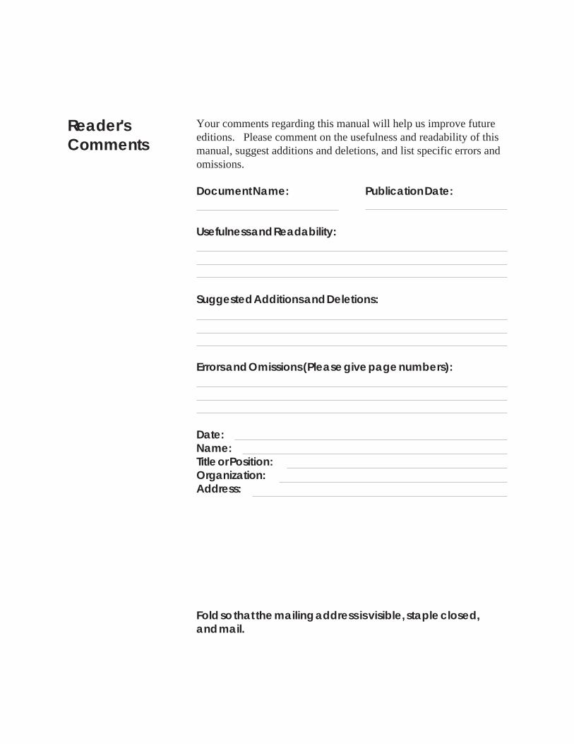
Reader'sComments
Fold so that the mailing address is visible, staple closed,and mail.
Your comments regarding this manual will help us improve futureeditions. Please comment on the usefulness and readability of thismanual, suggest additions and deletions, and list specific errors andomissions.
Document Name: Publication Date:
Usefulness and Readability:
Suggested Additions and Deletions:
Errors and Omissions (Please give page numbers):
Date:Name:Title or Position:Organization:Address:
Carrier CorporationCarrier World Headquarters Building
One Carrier PlaceFarmington, CT 06034-4015
Attn: CCN Documentation

Alarm Manager

Printed in U.S.A. 808 - 239 Rev. 01/03