01en 00 rx-v1800 rtl - yamaha corporation · yamaha canada music ltd. 135 milner ave., scarborough,...
TRANSCRIPT
YAMAHA ELECTRONICS CORPORATION, USA 6660 ORANGETHORPE AVE., BUENA PARK, CALIF. 90620, U.S.A.YAMAHA CANADA MUSIC LTD. 135 MILNER AVE., SCARBOROUGH, ONTARIO M1S 3R1, CANADAYAMAHA ELECTRONIK EUROPA G.m.b.H. SIEMENSSTR. 22-34, 25462 RELLINGEN BEI HAMBURG, GERMANYYAMAHA ELECTRONIQUE FRANCE S.A. RUE AMBROISE CROIZAT BP70 CROISSY-BEAUBOURG 77312 MARNE-LA-VALLEE CEDEX02, FRANCEYAMAHA ELECTRONICS (UK) LTD. YAMAHA HOUSE, 200 RICKMANSWORTH ROAD WATFORD, HERTS WD18 7GQ, ENGLANDYAMAHA SCANDINAVIA A.B. J A WETTERGRENS GATA 1, BOX 30053, 400 43 VÄSTRA FRÖLUNDA, SWEDENYAMAHA MUSIC AUSTRALIA PTY, LTD. 17-33 MARKET ST., SOUTH MELBOURNE, 3205 VIC., AUSTRALIA
© 2007 All rights reserved.
RX
-V1800
Printed in Malaysia WK69300
RX-V1800AV Receiver
OWNER’S MANUALMANUAL DE INSTRUCCIONES
RTL
RX-V1800_RTL-cv.fm Page 1 Thursday, July 5, 2007 1:26 AM
En
1 To assure the finest performance, please read this manual carefully. Keep it in a safe place for future reference.
2 Install this sound system in a well ventilated, cool, dry, clean place – away from direct sunlight, heat sources, vibration, dust, moisture, and/or cold. Allow ventilation space of at least 30 cm on the top, 20 cm on the left and right, and 20 cm on the back of this unit.
3 Locate this unit away from other electrical appliances, motors, or transformers to avoid humming sounds.
4 Do not expose this unit to sudden temperature changes from cold to hot, and do not locate this unit in an environment with high humidity (i.e. a room with a humidifier) to prevent condensation inside this unit, which may cause an electrical shock, fire, damage to this unit, and/or personal injury.
5 Avoid installing this unit where foreign objects may fall onto this unit and/or this unit may be exposed to liquid dripping or splashing. On the top of this unit, do not place:– Other components, as they may cause damage and/or
discoloration on the surface of this unit.– Burning objects (i.e. candles), as they may cause fire,
damage to this unit, and/or personal injury.– Containers with liquid in them, as they may fall and liquid
may cause electrical shock to the user and/or damage to this unit.
6 Do not cover this unit with a newspaper, tablecloth, curtain, etc. in order not to obstruct heat radiation. If the temperature inside this unit rises, it may cause fire, damage to this unit, and/or personal injury.
7 Do not plug in this unit to a wall outlet until all connections are complete.
8 Do not operate this unit upside-down. It may overheat, possibly causing damage.
9 Do not use force on switches, knobs and/or cords.10 When disconnecting the power cable from the wall outlet,
grasp the plug; do not pull the cable.11 Do not clean this unit with chemical solvents; this might
damage the finish. Use a clean, dry cloth.12 Only voltage specified on this unit must be used. Using this
unit with a higher voltage than specified is dangerous and may cause fire, damage to this unit, and/or personal injury. Yamaha will not be held responsible for any damage resulting from use of this unit with a voltage other than specified.
13 To prevent damage by lightning, keep the power cord and outdoor antennas disconnected from a wall outlet or the unit during a lightning storm.
14 Do not attempt to modify or fix this unit. Contact qualified Yamaha service personnel when any service is needed. The cabinet should never be opened for any reasons.
15 When not planning to use this unit for long periods of time (i.e. vacation), disconnect the AC power plug from the wall outlet.
16 Install this unit near the AC outlet and where the AC power plug can be reached easily.
17 Be sure to read the “Troubleshooting” section on common operating errors before concluding that this unit is faulty.
18 Before moving this unit, press AMASTER ON/OFF to release it outward to the OFF position to turn off this unit, the main room, Zone 2 and Zone 3 and then disconnect the AC power plug from the AC wall outlet.
19 VOLTAGE SELECTOR (Asia and General models only)The VOLTAGE SELECTOR on the rear panel of this unit must be set for your local main voltage BEFORE plugging into the AC wall outlet. Voltages are:
................................AC 110/120/220/230–240 V, 50/60 Hz20 The batteries shall not be exposed to excessive heat such as
sunshine, fire or like.21 Excessive sound pressure from earphones and headphones can
cause hearing loss.
Caution: Read this before operating your unit.
WARNINGTO REDUCE THE RISK OF FIRE OR ELECTRIC SHOCK, DO NOT EXPOSE THIS UNIT TO RAIN OR MOISTURE.
As long as this unit is connected to the AC wall outlet, it is not disconnected from the AC power source even if you turn off this unit by AMASTER ON/OFF. In this state, this unit is designed to consume a very small quantity of power.

1 En
PR
EPA
RA
TIO
NIN
TR
OD
UC
TIO
NB
AS
IC
OP
ER
AT
ION
AD
VAN
CE
D
OP
ER
AT
ION
AD
DIT
ION
AL
IN
FO
RM
AT
ION
AP
PE
ND
IXE
ng
lish
Notice ....................................................................... 2Features ................................................................... 3
Supplied accessories .................................................. 4Getting started ........................................................ 5Quick start guide .................................................... 6
Connections ........................................................... 12Optimizing the speaker setting for your listening
room ................................................................... 37Using AUTO SETUP .............................................. 37
Playback ................................................................ 42Basic procedure ....................................................... 42Selecting audio input jacks
(AUDIO SELECT).............................................. 43Selecting the MULTI CH INPUT component......... 43Using your headphones............................................ 43Muting the audio output........................................... 44Displaying the input source information
(SIGNAL INFO) ................................................. 44Playing video sources
in the background of an audio source.................. 45Using the sleep timer ............................................... 45
Sound field programs ........................................... 46Selecting sound field programs ............................... 46Sound field program descriptions............................ 46Enjoying unprocessed input sources........................ 51
Using audio features ............................................. 52Enjoying pure hi-fi sound ........................................ 52Adjusting the tonal quality....................................... 52Adjusting the speaker level...................................... 53Enjoying multi-channel sources
in 2-channel stereo............................................... 53FM/AM tuning ...................................................... 54
Automatic tuning ..................................................... 54Manual tuning.......................................................... 54Automatic preset tuning........................................... 55Manual preset tuning ............................................... 55Selecting preset stations........................................... 56Exchanging preset stations ...................................... 57
Radio Data System tuning (Europe model only) ......................................... 58Displaying the Radio Data System information ...... 58Selecting the Radio Data System program type
(PTY SEEK mode) .............................................. 59Using the enhanced other networks
(EON) data service .............................................. 60Using iPod™.......................................................... 61
Controlling iPod™................................................... 61Recording .............................................................. 63
Advanced sound configurations...........................64Changing sound field parameter settings................. 64Selecting decoders ................................................... 69
Customizing this unit (MANUAL SETUP).........72Using SET MENU................................................... 761 BASIC MENU...................................................... 772 VOLUME MENU ................................................ 813 SOUND MENU.................................................... 824 INPUT MENU...................................................... 855 OPTION MENU................................................... 88
Saving and recalling the system settings (SYSTEM MEMORY)......................................93Saving the current system settings........................... 93Loading the stored system settings .......................... 94Using examples........................................................ 95
Remote control features........................................97Controlling this unit, a TV, or other components.... 97Setting remote control codes ................................... 99Programming codes from other remote controls ... 101Changing source names in the display window..... 102Macro programming features ................................ 103Clearing configurations ......................................... 106
Using multi-zone configuration..........................108Connecting the Zone 2 and Zone 3 components ... 108Controlling Zone 2 or Zone 3 ................................ 109
Advanced setup....................................................113Using the advanced setup menu ............................ 113
Troubleshooting...................................................117Resetting the system............................................124Glossary................................................................125Sound field program information......................129Parametric equalizer information .....................130Specifications .......................................................131Index .....................................................................133
(at the end of this manual)
Front Panel ...............................................................iRemote Control ...................................................... iiSound output in each sound field program......... iiiList of remote control codes ...................................v
Contents
INTRODUCTION
PREPARATION
BASIC OPERATION
ADVANCED OPERATION
ADDITIONAL INFORMATION
APPENDIX
“AMASTER ON/OFF” or “1DVD” (example) indicates the name of the parts on the front panel or the remote control. Refer to the attached sheet or the pages at the end of this manual for the information about each position of the parts.
NOTICE
Manufactured under license from Dolby Laboratories.“Dolby”, “Pro Logic”, and the double-D symbol are trademarks of Dolby Laboratories.
Manufactured under license under U.S. Patent No’s: 5,451,942;5,956,674;5,974,380;5,978,762;6,226,616;6,487,535 & other U.S. and worldwide patents issued & pending. DTS is a registered trademark and the DTS logos, Symbol, DTS-HD and DTS-HD Master Audio are trademark of DTS, Inc. © 1996-2007 DTS, Inc. All Rights Reserved.
“iPod” is a trademark of Apple Inc., registered in the U.S. and other countries.
“HDMI”, the “HDMI” logo, and “High-Definition Multimedia Interface” are trademarks or registered trademarks of HDMI Licensing LLC.
“SILENT CINEMA” is a trademark of YAMAHA CORPORATION.
Notice
About this manual
• y indicates a tip for your operation.• Some operations can be performed by using either the
buttons on the front panel or the ones on the remote control. In case the button names differ between the front panel and the remote control, the button name on the remote control is given in parentheses.
• This manual is printed prior to production. Design and specifications are subject to change in part as a result of improvements, etc. In case of differences between the manual and product, the product has priority.
• “AMASTER ON/OFF” or “1DVD” (example) indicates the name of the parts on the front panel or the remote control. Refer to the attached sheet or the pages at the end of this manual for the information about each position of the parts.
• The symbol “ ” with page number(s) indicates the corresponding reference page(s).
• The shape of the illustration (for example, speaker terminals, input/output jacks, AC outlets, etc.) in this manual may vary depending on the model.
iPodTM
2 En

FEATURESIN
TR
OD
UC
TIO
NE
ng
lish
Built-in 7-channel power amplifier Minimum RMS output power
(20 Hz to 20 kHz, 0.04% THD, 8 Ω)Front: 130 W + 130 WCenter: 130 WSurround: 130 W + 130 WSurround back: 130 W + 130 W
Sound field programs Proprietary Yamaha technology for the creation of sound
fields Compressed Music Enhancer mode to improve the sound
quality of compression artifacts (such as the MP3 format) to that of a high-quality multi-channel source playback
Virtual CINEMA DSP SILENT CINEMA
Digital audio decoders Dolby TrueHD, Dolby Digital Plus decoder DTS-HD Master Audio, DTS-HD High Resolution Audio
decoder Dolby Digital/Dolby Digital EX decoder DTS/DTS-ES Matrix 6.1, Discrete 6.1, DTS 96/24 decoder Dolby Pro Logic/Dolby Pro Logic II/Dolby Pro Logic IIx
decoder DTS NEO:6 decoder
Sophisticated FM/AM tuner 40-station random and direct preset tuning Automatic preset tuning Preset station shifting capability (preset editing) Radio Data System capability (Europe model only)
HDMI™ (High-Definition Multimedia Interface) HDMI interface for standard, enhanced or
high-definition video as well as multi-channel digital audio based on HDMI version 1.3a
Automatic audio and video synchronization (lip sync) information capability
Deep Color video signal (30/36 bits) transmission capability High refresh rate and high resolution video signals capability High definition digital audio format signals capability Analog video to HDMI digital video up-conversion
(composite video ↔ S-video ↔ component video → HDMI digital video) capability for monitor out
Analog video up-scaling from 480i (NTSC)/576i (PAL) or 480p/576p to 720p, 1080i or 1080p
iPod™ controlling capability DOCK terminal to connect a Yamaha iPod universal dock
(such as the YDS-10, sold separately), which supports iPod (Click and Wheel), iPod nano, and iPod mini
Other features YPAO (Yamaha Parametric Room Acoustic Optimizer) for
automatic speaker setup 192-kHz/24-bit D/A converter OSD (on-screen display) menus that allow you to optimize
this unit to suit your individual audiovisual system 6 or 8-channel additional input jacks for discrete multi-
channel input Analog video interlace/progressive conversion from
480i (NTSC)/576i (PAL) to 480p/576p S-video signal input/output capability Component video input/output capability includes
(3 COMPONENT VIDEO INs and 1 MONITOR OUT) Optical and coaxial digital audio signal jacks Pure Direct mode for pure hi-fi sound for all sources Adaptive dynamic range controlling capability Adaptive DSP effect level controlling capability Remote control with preset remote control codes, learning and
macro capability ZONE 2/ZONE 3 custom installation facility Zone switching capability between the main zone and
ZONE 2/ZONE 3 using ZONE CONTROLS SYSTEM MEMORY capability for saving and recalling
multiple system parameter settings Sleep timer
Features
3 En

Features
Check that you received all of the following accessories.
The form of the supplied accessories varies depending on the models.
Supplied accessories
Note
Remote controlBatteries (6)
(AAA, R03, UM-4)(except Europe model)
AM loop antenna
Optimizer microphoneSpeaker terminal wrench Power cables(Two for Asia model)
Indoor FM antenna
TUNER CD CD-R
MD/TAPE DVD BD/HD DVD PHONO
DTV/CBL VCR V-AUX/DOCKDVR
POWER
STANDBY
A/B/C/D/E
PRESET VOLUME
ZONE 3ZONE 2ID2ID1
MUTE
Zone 2/Zone 3 remote control
(except Europe model)
Batteries (4) (AAA, R03, UM-4)(Europe model)
Batteries (4) (AAA, R03, UM-4)(Europe model)
–
+ +
––
+
ENTER
DISPLAY
AUDIO
MENUTITLE
TV MUTE TV INPUT MUTE
432
ENT+1009
5
1
AVTV
76 8
RETURN
ONOFF CLEARLEARN RENAMEMACRO
REC
DISC SKIP
VOLUMECHTV VOL
EFFECT
PARAMETER
FREQ/TEXT EON MODE – PTY SEEK – START
STRAIGHTA/B/C/D/E
SRCH MODE
PURE DIRECTPRESET/CH
SET MENU
BAND
LEVEL
CLASSICAL LIVE/CLUB ENTERTAIN MOVIE
SYSTEM MEMORY
SUR. DECODEENHANCERSTEREO
TV
SOURCE
AMP
SELECT
DTV/CBL VCRDVR V-AUX/DOCK
TUNER CD CD-R MULTI CH IN
POWER POWER POWERSTANDBY
SLEEPAUDIO SEL
DVD BD/HD DVD PHONOMD/TAPE
4 En

GETTING STARTEDIN
TR
OD
UC
TIO
NE
ng
lish
Installing batteries in the remote control
1 Press the part and slide the battery compartment cover off.
2 Insert the four supplied batteries (AAA, R03, UM-4) according to the polarity markings (+ and –) on the inside of the battery compartment.
3 Slide the cover back until it snaps into place.
Installing batteries in the Zone 2/Zone 3 remote control (Except Europe model)
1 Take off the battery compartment cover.
2 Insert the two supplied batteries (AAA, R03, UM-4) according to the polarity markings (+ and –) on the inside of the battery compartment.
3 Snap the battery compartment cover back into place.
• Change all of the batteries if you notice the following conditions:– the operation range of the remote control decreases.– the transmit indicator (O) does not flash or its light becomes
dim.• Do not use old batteries together with new ones.• Do not use different types of batteries (such as alkaline and
manganese batteries) together. Read the packaging carefully as these different types of batteries may have the same shape and color.
• If the batteries have leaked, dispose of them immediately. Avoid touching the leaked material or letting it come into contact with clothing, etc. Clean the battery compartment thoroughly before installing new batteries.
• Do not throw away batteries with general house waste; dispose of them correctly in accordance with your local regulations.
• If the remote control is without batteries for more than 2 minutes, or if exhausted batteries remain in the remote control, the contents of the memory may be cleared. When the memory is cleared, insert new batteries, set up the remote control code and program any acquired functions that may have been cleared.
VOLTAGE SELECTOR(Asia and General models only)
Getting started
13
2
1 3
2
Notes
Caution
The VOLTAGE SELECTOR on the rear panel of this unit must be set for your local voltage BEFORE plugging the power cable into the AC wall outlet. Improper setting of the VOLTAGE SELECTOR may cause damage to this unit and create a potential fire hazard.Rotate the VOLTAGE SELECTOR clockwise or counterclockwise to the correct position using a straight slot screwdriver.Voltages are as follows: AC 110/120/220/230–240 V, 50/60 Hz
230-240V
VOLTAGESELECTOR
Voltage indication
5 En
QUICK START GUIDE
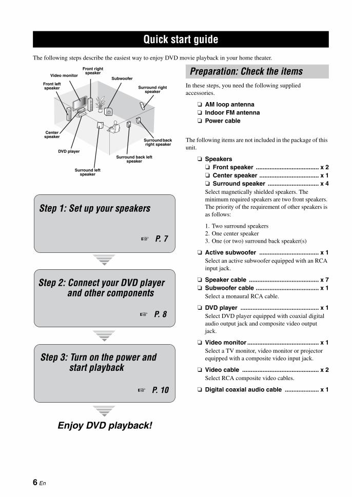
The following steps describe the easiest way to enjoy DVD movie playback in your home theater.
In these steps, you need the following supplied accessories.
AM loop antenna Indoor FM antenna Power cable
The following items are not included in the package of this unit.
Speakers Front speaker ..................................... x 2 Center speaker ................................... x 1 Surround speaker .............................. x 4Select magnetically shielded speakers. The minimum required speakers are two front speakers. The priority of the requirement of other speakers is as follows:
1. Two surround speakers2. One center speaker3. One (or two) surround back speaker(s)
Active subwoofer ................................... x 1Select an active subwoofer equipped with an RCA input jack.
Speaker cable ......................................... x 7 Subwoofer cable ..................................... x 1
Select a monaural RCA cable.
DVD player .............................................. x 1Select DVD player equipped with coaxial digital audio output jack and composite video output jack.
Video monitor .......................................... x 1Select a TV monitor, video monitor or projector equipped with a composite video input jack.
Video cable ............................................. x 2Select RCA composite video cables.
Digital coaxial audio cable .................... x 1
Quick start guide
Front right speaker
Subwoofer
Surround back right speaker
Surround left speaker
Front left speaker
Surround back left speaker
Surround right speaker
Center speaker
Video monitor
DVD player
Enjoy DVD playback!
Step 1: Set up your speakers
P. 7
Step 2: Connect your DVD player and other components
Step 3: Turn on the power and start playback
P. 8
P. 10
Preparation: Check the items
6 En
Quick start guideIN
TR
OD
UC
TIO
NE
ng
lish
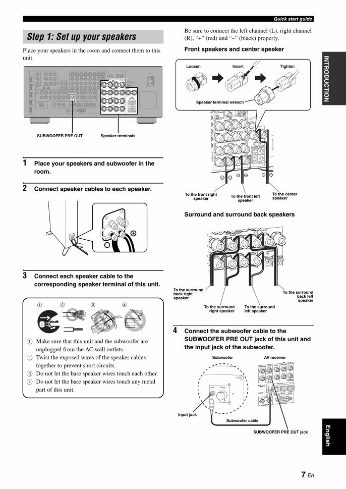
Place your speakers in the room and connect them to this unit.
1 Place your speakers and subwoofer in the room.
2 Connect speaker cables to each speaker.
3 Connect each speaker cable to the corresponding speaker terminal of this unit.
1 Make sure that this unit and the subwoofer are unplugged from the AC wall outlets.
2 Twist the exposed wires of the speaker cables together to prevent short circuits.
3 Do not let the bare speaker wires touch each other.4 Do not let the bare speaker wires touch any metal
part of this unit.
Be sure to connect the left channel (L), right channel (R), “+” (red) and “–” (black) properly.
Front speakers and center speaker
Surround and surround back speakers
4 Connect the subwoofer cable to the SUBWOOFER PRE OUT jack of this unit and the input jack of the subwoofer.
Step 1: Set up your speakers
AC IN
AC OUTLETS
HOLDERWRENCH
SPEAKERS
CENTERBI-AMP
SURROUND BACK/
PRESENCE/ZONE 2/ZONE 3SP1
FRONT
SURROUNDZONE 2/ZONE 3
SINGLE
SP2
ANTENNA
FM GND AM75Ω UNBAL.
VIDEO
S VIDEO
MONITOR OUTVIDEO
REMOTE
PHONOGND CD
IN(PLAY) OUT(REC)
CD-R
HDMI COMPONENT VIDEO
AUDIODOCK DIGITAL INPUT
MULTI CH INPUT PRE OUT
TRIGGER OUT RS-232C
DIGITAL OUTPUTZONE OUT
SUBWOOFER
SUBWOOFER
CENTER CENTERFRONT(6CH) FRONTSURROUND SURROUND
PRESENCESUR.BACK/
SINGLE(SB) ZONE 2 ZONE 3
CD DVD DVR
COAXIAL
1 2
CD BD/HD DVD
DTV/CBL
MD/ TAPEDVD CD-R
OPTICAL
987654321
SB(8CH)
DVD
TAPEMD/
(REC)(PLAY)IN OUT
BD/HD DVD VCRDVRDTV/CBL OUT OUTININBD/HD DVD DVD DTV/CBLMONITOR OUT
Y
PR
Y
PR
PB PB
IN OUT
DVR
DTV/CBL
DVD
BD/HD DVD
OUT
+
+ +
A B C
R L
R
R
L
R
L
+ + +R L
+ +R L
+ +R L
L
IN2
IN3
IN4
IN1
SUBWOOFER PRE OUT Speaker terminals
1 2 3 4
1 2 3 4
To the front left speaker
To the front right speaker
Loosen Insert Tighten
To the center speaker
Speaker terminal wrench
To the surround back right speaker
To the surroundback leftspeaker
To the surroundright speaker
To the surround left speaker
SUBWOOFER PRE OUT jack
Input jack
AV receiverSubwoofer
Subwoofer cable
7 En

Quick start guide
1 Connect the digital coaxial audio cable to the digital coaxial audio output jack of your DVD player and the DVD DIGITAL INPUT COAXIAL jack of this unit.
y• When you connect a component that has only a SCART
jack, use an appropriate converter. The connection between a converter and this unit depends on signals that are available on the converter. For details, refer to the instructions of your converter.
• This unit cannot transmit RGB signals.
2 Connect the video cable to the composite video output jack of your DVD player and the DVD VIDEO jack of this unit.
3 Connect the video cable to the VIDEO MONITOR OUT jack of this unit and the video input jack of your video monitor.
Step 2: Connect your DVD player and other components
AC IN
AC OUTLETS
HOLDERWRENCH
SPEAKERS
CENTERBI-AMP
SURROUND BACK/
PRESENCE/ZONE 2/ZONE 3SP1
FRONT
SURROUNDZONE 2/ZONE 3
SINGLE
SP2
ANTENNA
FM GND AM75Ω UNBAL.
VIDEO
S VIDEO
MONITOR OUTVIDEO
REMOTE
PHONOGND CD
IN(PLAY) OUT(REC)
CD-R
HDMI COMPONENT VIDEO
AUDIODOCK DIGITAL INPUT
MULTI CH INPUT PRE OUT
TRIGGER OUT RS-232C
DIGITAL OUTPUTZONE OUT
SUBWOOFER
SUBWOOFER
CENTER CENTERFRONT(6CH) FRONTSURROUND SURROUND
PRESENCESUR.BACK/
SINGLE(SB) ZONE 2 ZONE 3
CD DVD DVR
COAXIAL
1 2
CD BD/HD DVD
DTV/CBL
MD/ TAPEDVD CD-R
OPTICAL
987654321
SB(8CH)
DVD
TAPEMD/
(REC)(PLAY)IN OUT
BD/HD DVD VCRDVRDTV/CBL OUT OUTININBD/HD DVD DVD DTV/CBLMONITOR OUT
Y
PR
Y
PR
PB PB
IN OUT
DVR
DTV/CBL
DVD
BD/HD DVD
OUT
+
+ +
A B C
R L
R
R
L
R
L
+ + +R L
+ +R L
+ +R L
L
IN2
IN3
IN4
IN1
Make sure that this unit and the DVD player are unplugged from the AC wall outlets.
VIDEO MONITOR OUTDVD VIDEO
DVD DIGITAL INPUT COAXIAL
Digital coaxialaudio output
jackDigital coaxial audio
cable DVD DIGITAL INPUTCOAXIAL jack
DVD player AV receiver
Composite video output jack
Video cable
DVD VIDEO jack
DVD playerAV receiver
Video monitor AV receiver
Video cable VIDEO MONITOR OUT jackVideo input jack
8 En

Quick start guideIN
TR
OD
UC
TIO
NE
ng
lish
4 Connect the supplied AM loop antenna and indoor FM antenna to this unit.
The types of the supplied indoor FM antenna and the FM antenna terminal of this unit are different depending on the models.
Connecting the wire of the AM loop antenna
yThe wire of the AM loop antenna does not have any polarity and you can connect either end of the wire to AM or GND terminal.
Assembling the supplied AM loop antenna
5 Connect the supplied power cable to this unit and then plug the power cable and other components into the AC wall outlet.
y• This unit is equipped with AC OUTLET(S) that provide(s)
power to other components (except Korea model). See page 32 for details.
• (Asia model only) Select one of the supplied power cables suitable for the type of AC wall outlet in your location before plugging this unit into the AC wall outlet.
Note
Indoor FM antenna
AM loop antenna
Press and hold the tab
Insert Release the tab
For further connections
• Using other kinds of speaker combinations P. 14
• Connecting a video monitor via various ways of connection P. 24
• Connecting a DVD player via various ways of connection P. 25
• Connecting a DVD recorder or a digital video recorder P. 27
• Connecting a set-top box P. 27
• Connecting a CD player, an MD recorder, or a turntable P. 28
• Connecting an external amplifier P. 29
• Connecting a DVD player via multi-channel analog audio connection P. 30
• Connecting a Yamaha iPod universal dock P. 31
• Using the REMOTE IN/OUT jacks P. 31
• Using the VIDEO AUX jacks on the front panel P. 31
• Connecting an outdoor FM/AM antenna P. 32
General connection information
• General information on jacks and cable plugs P. 20
• General information on HDMI P. 21–22
• Speaker impedance setting P. 33
9 En

Quick start guide
1 Turn on the video monitor connected to this unit.
2 Press AMASTER ON/OFF inward to the ON position on the front panel.
3 Rotate the CINPUT selector to set the input source to “DVD”.
y• The recommended sound field program is set for each
input source (DVD, etc.). You can also use various sound field programs and other sound modes for playback. Refer to the following pages for details:– see pages 46 to 50 to use various sound field programs– see page 51 to turn on or off the sound effect– see page 52 to use the Pure Direct mode for high
fidelity sound• You can also set the input source to “TUNER” to use the
FM/AM tuning feature. For information on the FM/AM tuning, see pages 54 to 57.
4 Start playback of the desired DVD on your player.
5 Rotate QVOLUME to adjust the volume.
After using this unit...
Press BMAIN ZONE ON/OFF to set this unit to the standby mode.
This unit is set to the standby mode and consumes a small amount of power in order to receive infrared signals from the remote control. To turn on this unit from the standby mode, press BMAIN ZONE ON/OFF on the front panel (or 8POWER on the remote control). See page 33 for details.
Step 3: Turn on the power and start playback
Check the type of the connected speakers.If the speakers are 6-ohm speakers, set “SPEAKER IMP.” to “6Ω MIN” before using this unit (see page 33). You can also use 4-ohm speakers as the front speakers (see page 113).
10 En

Quick start guideIN
TR
OD
UC
TIO
NE
ng
lish
What do you want to do with this unit?
Using various input sources
• Basic operations of this unit P. 42
• Enjoying FM/AM radio programs P. 54
• Enjoying Radio Data System programs P. 58
• Using your iPod with this unit P. 61
Using various sound features
• Using various sound field programs P. 46
• Using the Pure Direct mode for high fidelity sound P. 52
• Adjusting the tonal quality of the speakers P. 52
• Customizing the sound field programs P. 64
Adjusting the parameters of this unit
• Automatically optimizing the speaker parameters for your listening room (AUTO SETUP) P. 37
• Setting the remote control P. 97
Additional features
• Displaying the current input source signal information in the OSD P. 44
• Saving and recalling the system settings of this unit (SYSTEM MEMORY) P. 93
• Using headphones P. 43
• Using this unit in multiple rooms simultaneously (multi-zone configuration) P. 108
• Automatically turning off this unit P. 45
Manually adjusting various parameters of this unit
• Setting the basic speaker configuration P. 77
• Adjusting the balance of the speaker levels P. 79
• Setting the distance of each speaker P. 80
• Setting the parameters related to the volume level P. 81
• Adjusting the tonal quality by using the graphic equalizer P. 82
• Adjusting the lip sync function for the HDMI connection P. 84
• Assigning the input/output jacks of this unit P. 86
• Setting the parameters of the front panel display or OSD P. 88
• Setting the parameter related to the video signals P. 89
• Protecting the various settings P. 90
• Setting the parameters of the multi-zone feature P. 91
Adjusting the advanced parameters
• Setting the speaker impedance of the connected speakers P. 113
• Setting the parameters of this unit to default values P. 116
11 En
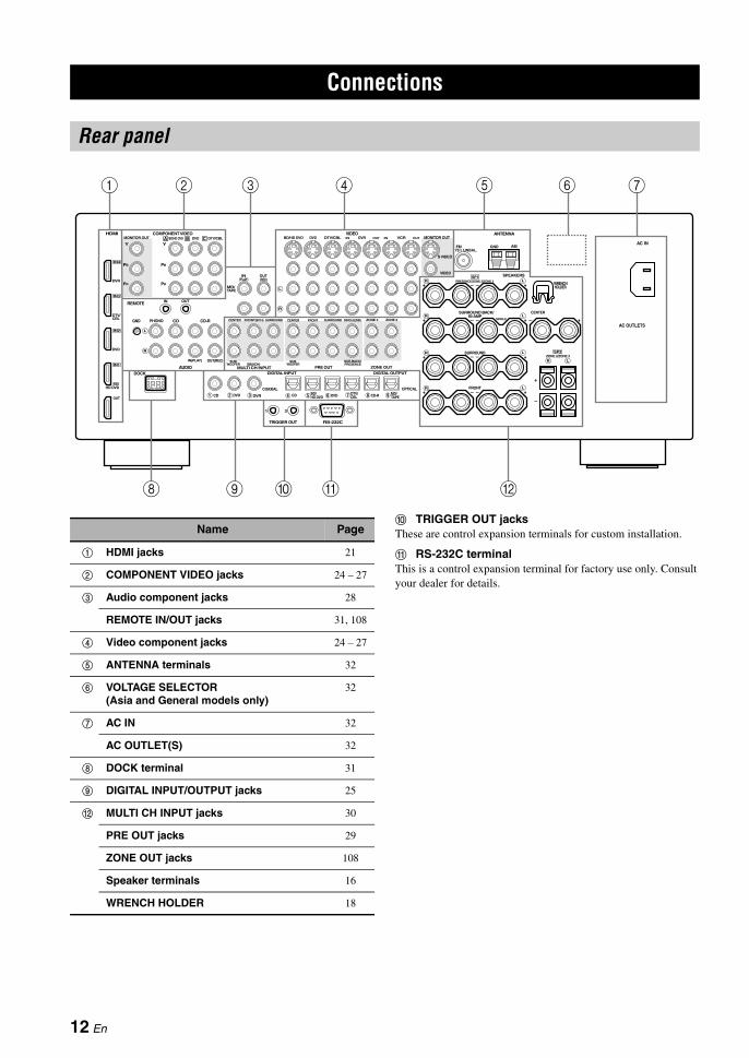
0 TRIGGER OUT jacksThese are control expansion terminals for custom installation.
A RS-232C terminalThis is a control expansion terminal for factory use only. Consult your dealer for details.
Connections
Rear panel
AC IN
AC OUTLETS
HOLDERWRENCH
SPEAKERS
CENTERBI-AMP
SURROUND BACK/
PRESENCE/ZONE 2/ZONE 3SP1
FRONT
SURROUNDZONE 2/ZONE 3
SINGLE
SP2
ANTENNA
FM GND AM75Ω UNBAL.
VIDEO
S VIDEO
MONITOR OUTVIDEO
REMOTE
PHONOGND CD
IN(PLAY) OUT(REC)
CD-R
HDMI COMPONENT VIDEO
AUDIODOCK DIGITAL INPUT
MULTI CH INPUT PRE OUT
TRIGGER OUT RS-232C
DIGITAL OUTPUTZONE OUT
SUBWOOFER
SUBWOOFER
CENTER CENTERFRONT(6CH) FRONTSURROUND SURROUND
PRESENCESUR.BACK/
SINGLE(SB) ZONE 2 ZONE 3
CD DVD DVR
COAXIAL
1 2
CD BD/HD DVD
DTV/CBL
MD/ TAPEDVD CD-R
OPTICAL
987654321
SB(8CH)
DVD
TAPEMD/
(REC)(PLAY)IN OUT
BD/HD DVD VCRDVRDTV/CBL OUT OUTININBD/HD DVD DVD DTV/CBLMONITOR OUT
Y
PR
Y
PR
PB PB
IN OUT
DVR
DTV/CBL
DVD
BD/HD DVD
OUT
+
+ +
A B C
R L
R
R
L
R
L
+ + +R L
+ +R L
+ +R L
L
IN2
IN3
IN4
IN1
2 31 4 5 6 7
0 A98 B
Name Page
1 HDMI jacks 21
2 COMPONENT VIDEO jacks 24 – 27
3 Audio component jacks 28
REMOTE IN/OUT jacks 31, 108
4 Video component jacks 24 – 27
5 ANTENNA terminals 32
6 VOLTAGE SELECTOR (Asia and General models only)
32
7 AC IN 32
AC OUTLET(S) 32
8 DOCK terminal 31
9 DIGITAL INPUT/OUTPUT jacks 25
B MULTI CH INPUT jacks 30
PRE OUT jacks 29
ZONE OUT jacks 108
Speaker terminals 16
WRENCH HOLDER 18
12 En

ConnectionsP
RE
PAR
AT
ION
En
glish
The speaker layout below shows the speaker setting we recommend. You can use it to enjoy the CINEMA DSP and multi-channel audio sources.
7.1-channel speaker layout7.1-channel speaker layout is highly recommended to play back the sound of high definition digital audio formats (Dolby TrueHD, DTS-HD Master Audio, etc.) as well as the conventional audio sources with sound field programs. See page 16 for connection information.
yWe recommend that you also add the presence speakers for the effect sounds of the CINEMA DSP sound field program. See page 46 for details.
Front left and right speakers (FL and FR)The front speakers are used for the main source sound plus effect sounds. Place these speakers at an equal distance from the ideal listening position. The distance of each speaker from each side of the video monitor should be the same.
Center speaker (C)The center speaker is for the center channel sounds (dialog, vocals, etc.). If for some reason it is not practical to use a center speaker, you can do without it. Best results, however, are obtained with the full system.
Surround left and right speakers (SL and SR)The surround speakers are used for effect and surround sounds.
Surround back left and right speakers (SBL and SBR)The surround back speakers supplement the surround speakers and provide more realistic front-to-back transitions.
Subwoofer (SW)The use of a subwoofer with a built-in amplifier, such as the Yamaha Active Servo Processing Subwoofer System, is effective not only for reinforcing bass frequencies from any or all channels, but also for reproducing the high fidelity sound of the LFE (low-frequency effect) channel included in bitstreams and multi-channel PCM sources. The position of the subwoofer is not so critical, because low bass sounds are not highly directional. But it is better to place the subwoofer near the front speakers. Turn it slightly toward the center of the room to reduce wall reflections.
Placing speakers
SW
FR
FLSBR
SBL
SL
SR
C
60˚
30˚
SBRSBL
FL FRC
SL
SR
SR80˚
SL
1.8 m (6 ft)
30 cm (12 in) or more
13 En

Connections
6.1-channel speaker layoutSee page 17 for connection information.
yWe recommend that you also add the presence speakers for the effect sounds of the CINEMA DSP sound field program. See page 15 for details.
Front left and right speakers (FL and FR)Center speaker (C)Surround left and right speakers (SL and SR)Subwoofer (SW)The functions and settings of each speaker are the same as those for the 7.1-channel speaker layout (see page 13).
Surround back speaker (SB)Connect a single surround speaker to the SURROUND BACK (SINGLE) speaker terminals and place the single surround back speaker behind the listening position. The surround back left and right channel signals are mixed down and output at the single surround back speaker when you set “SUR.B L/R SP” to “SMLx1” or “LRGx1” (see page 78).
5.1-channel speaker layoutSee page 17 for connection information.
yWe recommend that you also add the presence speakers for the effect sounds of the CINEMA DSP sound field program. See page 15 for details.
Front left and right speakers (FL and FR)Center speaker (C)Subwoofer (SW)The functions and settings of each speaker are the same as those for the 7.1-channel speaker layout (see page 13).
Surround left and right speakers (SL and SR)Connect the surround speakers to the SURROUND speaker terminals even if you place the surround speakers behind the listening position.For the smooth and unbroken sound field behind the listening position, place the surround left and right speakers farther back compared with the placement in the 7.1-channel speaker layout.The surround back channel signals are directed to the surround left and right speakers when “SUR.B L/R SP” is set to “NONE” (see page 78).
SW
FR
FL
SB
SL
SR
C
60˚
30˚
SB
FL FRC
SL
SR
SR80˚
SL
1.8 m (6 ft)
SW
FR
FL
SL
SR
C
60˚
30˚
FL FRC
SL
SR
SR80˚
SL
1.8 m (6 ft)
For other speaker combinationsYou can enjoy multi-channel sources with sound field programs by using a speaker combination other than the 7.1/6.1/5.1-channel speaker combinations.Use the automatic setup feature (see page 37) or set the “SPEAKER SET” parameters in “MANUAL SETUP” (see page 72) to output the surround sounds at the connected speakers.
14 En
ConnectionsP
RE
PAR
AT
ION
En
glish
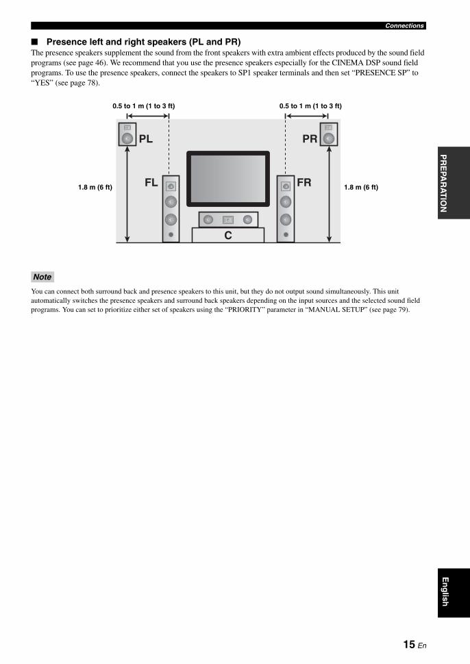
Presence left and right speakers (PL and PR)The presence speakers supplement the sound from the front speakers with extra ambient effects produced by the sound field programs (see page 46). We recommend that you use the presence speakers especially for the CINEMA DSP sound field programs. To use the presence speakers, connect the speakers to SP1 speaker terminals and then set “PRESENCE SP” to “YES” (see page 78).
You can connect both surround back and presence speakers to this unit, but they do not output sound simultaneously. This unit automatically switches the presence speakers and surround back speakers depending on the input sources and the selected sound field programs. You can set to prioritize either set of speakers using the “PRIORITY” parameter in “MANUAL SETUP” (see page 79).
Note
FR
PRPL
C
FL 1.8 m (6 ft)
0.5 to 1 m (1 to 3 ft) 0.5 to 1 m (1 to 3 ft)
1.8 m (6 ft)
15 En
Connections
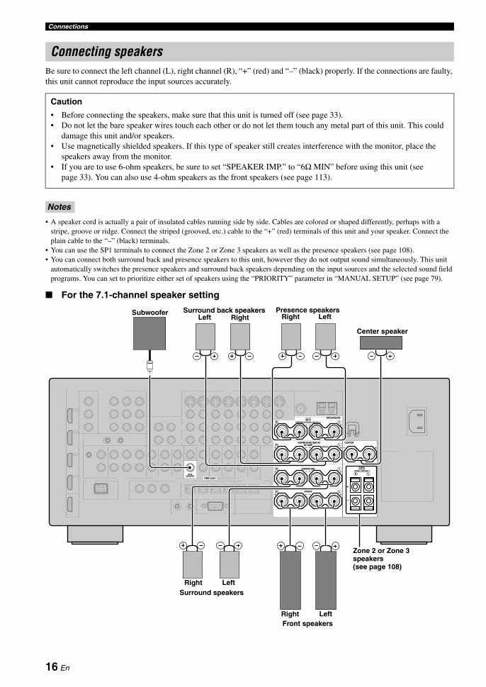
Be sure to connect the left channel (L), right channel (R), “+” (red) and “–” (black) properly. If the connections are faulty, this unit cannot reproduce the input sources accurately.
• A speaker cord is actually a pair of insulated cables running side by side. Cables are colored or shaped differently, perhaps with a stripe, groove or ridge. Connect the striped (grooved, etc.) cable to the “+” (red) terminals of this unit and your speaker. Connect the plain cable to the “–” (black) terminals.
• You can use the SP1 terminals to connect the Zone 2 or Zone 3 speakers as well as the presence speakers (see page 108).• You can connect both surround back and presence speakers to this unit, however they do not output sound simultaneously. This unit
automatically switches the presence speakers and surround back speakers depending on the input sources and the selected sound field programs. You can set to prioritize either set of speakers using the “PRIORITY” parameter in “MANUAL SETUP” (see page 79).
For the 7.1-channel speaker setting
Connecting speakers
Caution
• Before connecting the speakers, make sure that this unit is turned off (see page 33).• Do not let the bare speaker wires touch each other or do not let them touch any metal part of this unit. This could
damage this unit and/or speakers.• Use magnetically shielded speakers. If this type of speaker still creates interference with the monitor, place the
speakers away from the monitor.• If you are to use 6-ohm speakers, be sure to set “SPEAKER IMP.” to “6Ω MIN” before using this unit (see
page 33). You can also use 4-ohm speakers as the front speakers (see page 113).
Notes
SPEAKERS
CENTERBI-AMP
SURROUND BACK/
PRESENCE/ZONE 2/ZONE 3SP1
FRONT
SURROUNDZONE 2/ZONE 3
SINGLE
SP2
PRE OUT
SUBWOOFER
+
+ +
R L
R L
+ + +R L
+ +R L
+ +R L
Front speakers
Surround speakers
Presence speakersSubwoofer Right LeftLeft
Center speaker
Surround back speakersRight
Left
LeftRight
Right
Zone 2 or Zone 3 speakers(see page 108)
16 En

ConnectionsP
RE
PAR
AT
ION
En
glish
For the 6.1-channel speaker setting
For the 5.1-channel speaker setting
Surround back speaker
SPEAKERS
CENTERBI-AMP
SURROUND BACK/
PRESENCE/ZONE 2/ZONE 3SP1
FRONT
SURROUNDZONE 2/ZONE 3
SINGLE
SP2
PRE OUT
SUBWOOFER
+
+ +
R L
R L
+ + +R L
+ +R L
+ +R L
Front speakers
Surround speakers
Presence speakers(see pages 15 and 16)
Subwoofer
Center speaker
Left
LeftRight
Right
Zone 2 or Zone 3 speakers(see page 108)
SPEAKERS
CENTERBI-AMP
SURROUND BACK/
PRESENCE/ZONE 2/ZONE 3SP1
FRONT
SURROUNDZONE 2/ZONE 3
SINGLE
SP2
PRE OUT
SUBWOOFER
+
+ +
R L
R L
+ + +R L
+ +R L
+ +R L
Front speakers
Surround speakers
Subwoofer
Center speaker
Left
LeftRight
Right
Zone 2 or Zone 3 speakers(see page 108)
Front speakers for the bi-amplification connections (see page 19)
Presence speakers(see pages 15 and 16)
17 En

Connections
Connecting the speaker cable
1 Remove approximately 10 mm (0.4 in) of insulation from the end of each speaker cable and then twist the exposed wires of the cable together to prevent short circuits.
2 Loosen the knob using the supplied speaker terminal wrench.
3 Insert one bare wire into the hole on the side of each terminal.
4 Tighten the knob to secure the wire using the supplied speaker terminal wrench.
5 Hook the speaker terminal wrench onto WRENCH HOLDER on the rear panel of this unit when not in use.
Connecting to the SP2 speaker terminals
Connect Zone 2 or Zone 3 speakers to these terminals (see page 108).
1 Open the tab.
2 Insert one bare wire into the hole on the terminal.
3 Close the tab to secure the wire.
10 mm (0.4 in)
Speaker terminal wrench
Red: positive (+)Black: negative (–)
Red: positive (+)Black: negative (–)
18 En
ConnectionsP
RE
PAR
AT
ION
En
glish
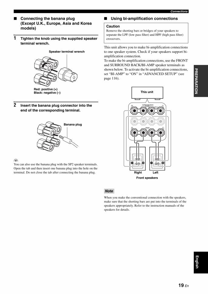
Connecting the banana plug(Except U.K., Europe, Asia and Korea models)
1 Tighten the knob using the supplied speaker terminal wrench.
2 Insert the banana plug connector into the end of the corresponding terminal.
yYou can also use the banana plug with the SP2 speaker terminals. Open the tab and then insert one banana plug into the hole on the terminal. Do not close the tab after connecting the banana plug.
Using bi-amplification connections
This unit allows you to make bi-amplification connections to one speaker system. Check if your speakers support bi-amplification connection.To make the bi-amplification connections, use the FRONT and SURROUND BACK/BI-AMP speaker terminals as shown below. To activate the bi-amplification connections, set “BI-AMP” to “ON” in “ADVANCED SETUP” (see page 116).
When you make the conventional connection with the speakers, make sure that the shorting bars are put into the terminals of the speakers appropriately. Refer to the instruction manuals of the speakers for details.
Red: positive (+)Black: negative (–)
Speaker terminal wrench
Banana plug
CautionRemove the shorting bars or bridges of your speakers to separate the LPF (low pass filter) and HPF (high pass filter) crossovers.
Note
BI-AMPSURROUND BACK/
FRONT
SINGLE
+ +
++
R L
SURROUND+ +R
R
L
L
This unit
LeftRight
Front speakers
19 En

Connections
Audio jacksThis unit has three types of audio jacks. Connection depends on the availability of audio jacks on your other components.
AUDIO jacksFor conventional analog audio signals transmitted via left and right analog audio cables. Connect red plugs to the right jacks and white plugs to the left jacks.
DIGITAL COAXIAL jacksFor digital audio signals transmitted via coaxial digital audio cables.
DIGITAL OPTICAL jacksFor digital audio signals transmitted via optical digital audio cables.
You can use the digital jacks to input PCM, Dolby Digital and DTS bitstreams. When you connect components to both the COAXIAL and OPTICAL jacks, priority is given to the signals input at the COAXIAL jack. All digital input jacks are compatible with up to 96-kHz sampling digital signals.
Video jacksThis unit has three types of video jacks. Connect the video input jacks of this unit to the video output jacks of the input source components to switch the audio and video sources simultaneously. Connection depends on the availability of input jacks on your video monitor.
VIDEO jacksFor conventional composite video signals transmitted via composite video cables.
S VIDEO jacksFor S-video signals, separated into the luminance (Y) and chrominance (C) video signals transmitted on separate wires of S-video cables.
COMPONENT VIDEO jacksFor component video signals, separated into the luminance (Y) and chrominance (PB, PR) video signals transmitted on separate wires of component video cables.
yThis unit is equipped with the video conversion function. See pages 23 and 89 for details.
Information on jacks and cable plugs
Note
COAXIAL
DIGITALAUDIO
OPTICAL
DIGITALRL
CORL
Left and right analog audio cable plugs
Optical digital
audio cable plug
Coaxial digital audio cable plug
Audio jacks and cable plugs
(Red)(White) (Orange)
VIDEO S VIDEOCOMPONENT VIDEO
Y R PB P
PBY PRSV
Composite video cable
plug
S-video cable plug
Component video cable
plugs
Video jacks and cable plugs
(Yellow) (Green) (Blue) (Red)
20 En

ConnectionsP
RE
PAR
AT
ION
En
glish
This unit has four HDMI input jacks and one HDMI output jack for digital audio and video signal input/output. Connect the HDMI IN 1, HDMI IN 2, HDMI IN 3, or HDMI IN 4 jack of this unit to the HDMI output jack of other HDMI components (such as a DVD player). Connect the HDMI OUT jack of this unit to the HDMI input jack of other HDMI components (such as a TV and a projector).The video or audio signals input at the HDMI IN jacks of the selected input source are output at the HDMI OUT jack of this unit.
You can check the potential problem about the HDMI connection (see page 44).
HDMI jack and cable plug
y• We recommend that you use a commercially available HDMI
cable shorter than 5 meters (16 feet) with the HDMI logo printed on it.
• Use a conversion cable (HDMI jack ↔ DVI-D jack) to connect this unit to other DVI components.
• Do not disconnect or connect the cable or turn off the power of the HDMI components connected to the HDMI OUT jack of this unit while data is being transferred. Doing so may disrupt playback or cause noise.
• The HDMI OUT jack outputs the audio signals input at the HDMI input jacks only even if “SUPPORT AUDIO” is set to “OTHER” (see page 85).
• If you turn off the power of the video monitor connected to the HDMI OUT jack via a DVI connection, this unit may fail to establish the connection to the component.
• The analog video signals input at the composite video, S-video and component video jacks can be digitally up-converted to be output at the HDMI OUT jack. Set “VIDEO CONV.” to “ON” in “MANUAL SETUP” (see page 89) to activate this feature.
Default input assignment of HDMI input jacks
Information on HDMI™
This HDMI interface of this unit is based on the following standards:• HDMI Version 1.3a (High-Definition Multimedia Interface Specification Version 1.3a) licensed by HDMI
Licensing, LLC.• HDCP (High-bandwidth Digital Content Protection System) licensed by Digital Content Protection, LLC.
Note
Notes
HDMI
HDMI cable plug
HDMI input jack Assigned input source
IN1 BD/HD DVD
IN2 DVD
IN3 DTV/CBL
IN4 DVR
21 En

Connections
HDMI signal compatibility with this unit
Audio signals
y• If the input source component can decode the bitstream audio
signals of audio commentaries, you can play back the audio sources with the audio commentaries mixed down by using the following connections:– multi-channel analog audio input (see page 30)– DIGITAL INPUT OPTICAL (or COAXIAL)
• Refer to the supplied instruction manuals of the input source component, and set the component appropriately.
• When CPPM copy-protected DVD audio is played back, video and audio signals may not be output depending on the type of the DVD player.
• This unit is not compatible with HDCP-incompatible HDMI or DVI components.
• To decode audio bitstream signals on this unit, set the input source component appropriately so that the component outputs the audio bitstream signals directly (does not decode the bitstream signals on the component). Refer to the supplied instruction manuals for details.
• This unit is not compatible with the audio commentary features (for example, the special audio contents downloaded via the Internet) of Blu-ray Disc or HD DVD. This unit does not play back the audio commentaries of the Blu-ray Disc or HD DVD contents.
Video signalsThis unit is compatible with the video signals of the following resolutions:
Video signal format– 480i/576i– 480p/576p– 720p– 1080i– 1080p
Refresh rate– 59.94(60)/50 Hz
This unit also accepts 30 or 36-bit Deep Color video signals.
Audio signal types
Audio signal formats
Compatible media
2ch Linear PCM
2ch, 32-192 kHz, 16/20/24 bit
CD, DVD-Video, DVD-Audio, etc.
Multi-ch Linear PCM
8ch, 32-192 kHz, 16/20/24 bit
DVD-Audio, etc.
DSD 2/5.1ch, 2.8224 MHz,1 bit
SACD, etc.
Bitstream Dolby Digital, DTS
DVD-Video, etc.
Bitstream (High definition audio)
Dolby TrueHD, Dolby Digital Plus, DTS-HD Master Audio, DTS-HD High Resolution Audio
Blu-ray Disc,HD DVD, etc.
Notes
22 En

ConnectionsP
RE
PAR
AT
ION
En
glish
Audio signal flow
• 2-channel as well as multi-channel PCM, Dolby Digital and DTS signals input at one of the HDMI input jacks can be output at the HDMI OUT jack only when “SUPPORT AUDIO” is set to “OTHER” (see page 85).
• The following types of audio signals can be only input at HDMI input jacks:– DSD– Dolby TrueHD– Dolby Digital Plus– DTS-HD Master Audio– DTS-HD High Resolution Audio
Video signal flow
yYou can deinterlace and convert the resolution of the video signals by using “VIDEO SET” parameters. See page 89 for details.
• When the analog video signals are input at the COMPONENT VIDEO, S VIDEO and VIDEO jacks, the priority order of the input signals is as follows: 1. COMPONENT VIDEO2. S VIDEO3. VIDEO
• Digital video signals input at the HDMI input jacks cannot be output from analog video output jacks.
• The analog component video signals (with 480i (NTSC)/576i (PAL) of resolution only) are converted to the S-video or composite video signals and output at the VIDEO or S VIDEO MONITOR OUT jacks.
• The analog component video signals with 1080p of resolution are only output at the COMPONENT VIDEO MONITOR OUT jacks.
• The OSD signal is not output at the DVR OUT and VCR OUT jacks and is not recorded.
Audio and video signal flow
Notes
DIGITAL AUDIO(OPTICAL)
DIGITAL AUDIO(COAXIAL)
HDMI
AUDIO
OutputInput
Analog output
Digital output
Notes
S VIDEO
VIDEO
COMPONENTVIDEO
HDMI
Through
OutputInput
Video conversion ON (see page 89)
23 En

Connections
Connect your TV (or projector) to the HDMI OUT jack, the COMPONENT VIDEO MONITOR OUT jacks, the S VIDEO MONITOR OUT jack or the VIDEO MONITOR OUT jack of this unit.
yYou can select to play back HDMI audio signals on this unit or on another HDMI component connected to the HDMI OUT jack on the rear panel of this unit. Use the “SUPPORT AUDIO” parameter in “SOUND MENU” to select the component to play back HDMI audio signals (see page 85).
• Some video monitors connected to this unit via a DVI connection fail to recognize the HDMI audio/video signals being input if they are in the standby mode. In this case, the HDMI indicator flashes irregularly.
• Set “VIDEO CONV.” in “OPTION MENU” to “ON” (see page 89) to display the short message displays and sound field parameter displays.
• The “SET MENU” and sound field parameter displays appear with the gray background depending on the input video signal format and the setting of the parameters in “DISPLAY SET” (see page 88).
• If the connected video monitor is compatible with the automatic audio and video synchronization feature (automatic lip sync feature), this unit adjusts the audio and video timing automatically (see page 84). Connect the video monitor to the HDMI OUT jack of this unit to use the feature.
Connecting a TV monitor or projector
Make sure that this unit and other components are unplugged from the AC wall outlets.
Notes
VIDEO
S VIDEO
MONITOR OUTVIDEOHDMI COMPONENT VIDEO
MONITOR OUT
Y
PR
PB
OUT
PRPB V SY
TV (or projector)
Video inComponent video in
S-video inHDMI in
indicates recommended connections
indicates alternative connections
24 En

ConnectionsP
RE
PAR
AT
ION
En
glish
• When “VIDEO CONV.” is set to “OFF” (see page 89), be sure to make the same type of video connections as those made for your TV (see page 24). For example, if you connected your TV to the VIDEO MONITOR OUT jack of this unit, connect your other components to the VIDEO jacks.
• When “VIDEO CONV.” is set to “ON” (see page 89), the converted video signals are output only at the MONITOR OUT jacks. When recording a source, you must make the same type of video connections between each component.
• To make a digital connection to a component other than the default component assigned to each DIGITAL INPUT or DIGITAL OUTPUT jack, select the corresponding setting for “OPTICAL OUT”, “OPTICAL IN”, or “COAXIAL IN” in “I/O ASSIGNMENT” (see page 86).
• If you connect your DVD player to both the DIGITAL INPUT OPTICAL and the DIGITAL INPUT COAXIAL jacks, priority is given to the signals input at the DIGITAL INPUT COAXIAL jack.
• The short message displays do not appear when the component video signals with 480p/576p, 720p, 1080i or 1080p resolutions are input.
Connecting a Blu-ray Disc or HD DVD playerConnect your Blu-ray Disc or HD DVD player to the HDMI IN 1 jack of this unit to perform the features of the Blu-ray Disc or HD DVD completely.
Connecting other components
Notes
Make sure that this unit and other components are unplugged from the AC wall outlets.
VIDEO
S VIDEO
VIDEOHDMI COMPONENT VIDEO
DIGITAL INPUT
BD/HD DVD
OPTICAL
5
BD/HD DVDBD/HD DVD
Y
PR
PB
BD/HD DVD
A
R
L
IN1
L R OVSPRPBY
Blu-ray Disc or HD DVD playerHDMI out
Component out
S-video out Video out
Optical out
Audio out
indicates recommended connections
indicates alternative connections
25 En
Connections
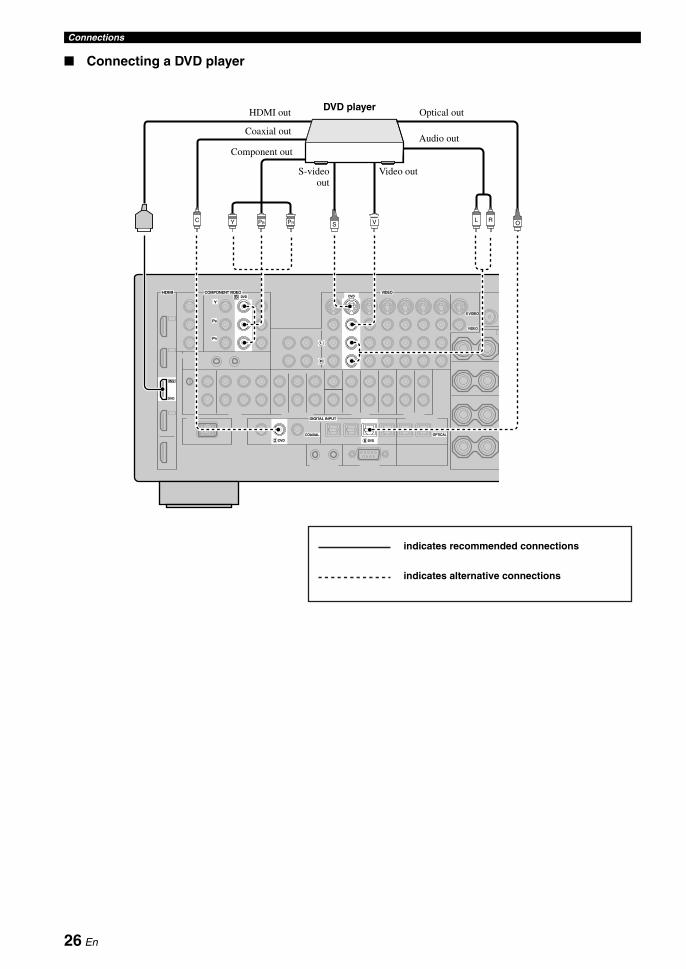
Connecting a DVD player
VIDEO
S VIDEO
VIDEOHDMI COMPONENT VIDEO
DIGITAL INPUT
DVD
COAXIAL
DVD
OPTICAL
62
DVDDVD
Y
PR
PB
DVD
B
R
L
IN2
C OVSL RPRPBY
DVD playerHDMI out
Coaxial out
Component out
S-videoout
Video out
Optical out
Audio out
indicates recommended connections
indicates alternative connections
26 En

ConnectionsP
RE
PAR
AT
ION
En
glish
Connecting a DVD recorder, PVR or VCR
* When you connect another VCR to this unit, connect it to the VCR terminals (S VIDEO IN, VIDEO IN, AUDIO IN, S VIDEO OUT, VIDEO OUT and AUDIO OUT jacks) same as DVR terminals except the DIGITAL INPUT (COAXIAL) jack.
Connecting a set-top box
Note
VIDEO
S VIDEO
VIDEOHDMI
DIGITAL INPUT
DVR
COAXIAL
3
VCRDVR OUT OUTININ
DVR
R
L
IN4
DVR OUTIN
RL R LV VS SC
DVD recorder, PVR or VCR
Coaxial out
S-video out
Video out
Audio in
Video in
S-video in
Audio out
HD
MI out
*
VIDEO
S VIDEO
VIDEOHDMI COMPONENT VIDEO
DIGITAL INPUT
DTV/CBL
OPTICAL
7
DTV/CBLDTV/CBL
Y
PR
PB
DTV/CBL
C
R
L
IN3
OV L RSPRPBY
Satellite receiver, cable TV receiver or HDTV
decoderHDMI out
Component out
Video out
Audio out
S-video out
Optical out
27 En
Connections
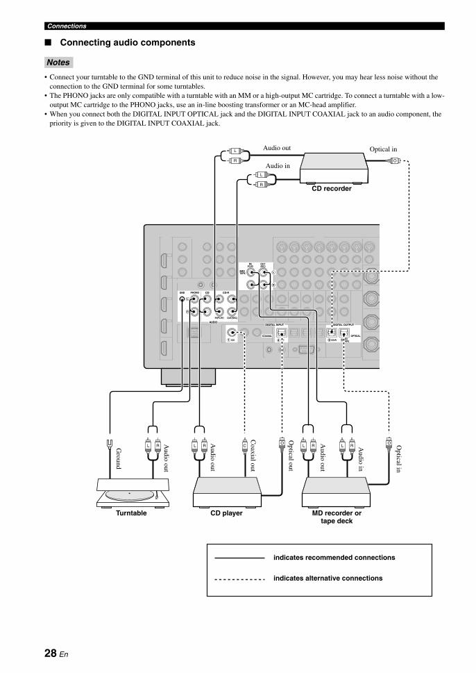
Connecting audio components
• Connect your turntable to the GND terminal of this unit to reduce noise in the signal. However, you may hear less noise without the connection to the GND terminal for some turntables.
• The PHONO jacks are only compatible with a turntable with an MM or a high-output MC cartridge. To connect a turntable with a low-output MC cartridge to the PHONO jacks, use an in-line boosting transformer or an MC-head amplifier.
• When you connect both the DIGITAL INPUT OPTICAL jack and the DIGITAL INPUT COAXIAL jack to an audio component, the priority is given to the DIGITAL INPUT COAXIAL jack.
Notes
PHONOGND CD
IN(PLAY) OUT(REC)
CD-R
AUDIODIGITAL INPUT DIGITAL OUTPUT
CD
COAXIAL
CD MD/ TAPECD-R
OPTICAL
9841
TAPEMD/
(REC)(PLAY)IN OUT
R
L
R
L
L RL RL RL R
L
R
L
R
COO
O
CD recorder
Turntable CD player MD recorder or tape deck
Audio in
Optical inAudio out
Optical out
Audio in
Audio out
Optical in
Ground
Audio out
Coaxial out
Audio out
indicates recommended connections
indicates alternative connections
28 En
ConnectionsP
RE
PAR
AT
ION
En
glish
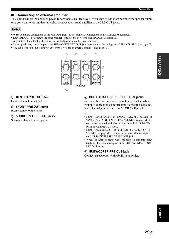
Connecting an external amplifierThis unit has more than enough power for any home use. However, if you want to add more power to the speaker output or if you want to use another amplifier, connect an external amplifier to the PRE OUT jacks.
• When you make connections to the PRE OUT jacks, do not make any connections to the SPEAKERS terminals.• Each PRE OUT jack outputs the same channel signals as the corresponding SPEAKERS terminals.• Adjust the volume level of the subwoofer with the control on the subwoofer unit.• Some signals may not be output at the SUBWOOFER PRE OUT jack depending on the settings for “SPEAKER SET” (see page 77).• You can use the automatic setup feature even if you use an external amplifier (see page 37).
1 CENTER PRE OUT jackCenter channel output jack.
2 FRONT PRE OUT jacksFront channel output jacks.
3 SURROUND PRE OUT jacksSurround channel output jacks.
4 SUR.BACK/PRESENCE PRE OUT jacksSurround back or presence channel output jacks. When you only connect one external amplifier for the surround back channel, connect it to the SINGLE (SB) jack.
y• Set the “SUR.B L/R SP” to “LRGx2”, “LRGx1”, “SMLx2” or
“SMLx1” and “PRESENCE SP” to “NONE” (see page 78) to output the surround back channel signals at the SUR.BACK/PRESENCE PRE OUT jacks.
• Set the “PRESENCE SP” to “YES” and “SUR.B L/R SP” to “NONE” (see page 78) to output the presence channel signals at the SUR.BACK/PRESENCE PRE OUT jacks.
• When “BI-AMP” is set to “ON” (see page 19), this unit output the front channel audio signals at the SUR.BACK/PRESENCE PRE OUT jacks.
5 SUBWOOFER PRE OUT jackConnect a subwoofer with a built-in amplifier.
Notes
PRE OUT
SUBWOOFER
CENTER FRONT SURROUND
PRESENCESUR.BACK/
SINGLE(SB)
R
L
5
4321
29 En

Connections
Connecting a multi-format player or an external decoderThis unit is equipped with 6 additional input jacks (left and right FRONT, CENTER, left and right SURROUND and SUBWOOFER) for discrete multi-channel input from a multi-format player, external decoder, sound processor or pre-amplifier.If you set “INPUT CH” to “8CH” in “MULTI CH” (see page 87), you can use the input jacks assigned as “FRONT” in “MULTI CH” together with the MULTI CH INPUT jacks to input 8-channel signals.Connect the output jacks on your multi-format player or external decoder to the MULTI CH INPUT jacks. Be sure to match the left and right outputs to the left and right input jacks for the front and surround channels.
• When you select the component connected to the MULTI CH INPUT jacks as the input source (see page 43), this unit automatically turns off the digital sound field processor, and you cannot select sound field programs.
• This unit does not redirect signals input at the MULTI CH INPUT jacks to accommodate for missing speakers. We recommend that you connect at least a 5.1-channel speaker system before using this feature.
• When the component connected to the MULTI CH INPUT jacks of this unit is selected as the input source, only the signals input at MULTI CH INPUT FRONT jacks are output from the connected headphones.
For 6-channel input For 8-channel input
* The analog audio input jacks assigned as “FRONT” in “MULTI CH” (see page 85).
Notes
MULTI CH INPUT
SUBWOOFER
CENTER FRONT(6CH) SURROUND
SB(8CH)
R
L
L R L R
Subw
ooferout
Multi-format player/External decoder
Center out
Surroundout
Front out
Note
MULTI CH INPUT
SUBWOOFER
SUB
CENTER FRONT(6CH) SURROUND
SB(8CH)
TAPEMD/
( C)( )
R
L
R
L
L R L RL R
Multi-format player/External decoder
Front out
Subwoofer
out
Center out
Surround back out
Surround out
*
30 En

ConnectionsP
RE
PAR
AT
ION
En
glish
Connecting a Yamaha iPod universal dock
This unit is equipped with the DOCK terminal on the rear panel that allows you to connect a Yamaha iPod universal dock (such as the YDS-10, sold separately), where you can station your iPod and control playback of your iPod using the supplied remote control. Connect a Yamaha iPod universal dock (such as the YDS-10, sold separately) to the DOCK terminal on the rear panel of this unit using its dedicated cable.
Using REMOTE IN/OUT jacksWhen the components are the Yamaha products and have the capability of the transmission of the remote control signals, connect the REMOTE IN and REMOTE OUT jack to the remote control input and output jack with the monaural analog mini cable as follows. See page 108 for more details of this feature.
Use the VIDEO AUX jacks on the front panel to connect a game console or a video camera to this unit.
The audio signals input at the DOCK terminal on the rear panel take priority over the ones input at the VIDEO AUX jacks.
DOCK
Yamaha iPod universal dock (such as the YDS-10,
sold separately)
REMOTE IN OUT
Yamaha component (CD or DVD player, etc.)
Remote control in
Remotecontrol out
Infrared signal receiver or
Yamaha component
Using the VIDEO AUX jacks on the front panel
CautionBe sure to turn down the volume of this unit and other components before making connections.
Note
MASTER
PURE DIRECT
VOLUME
MAIN ZONE
INPUT
OFFON
SLEEP
ZONE ON/OFF ZONE CONTROLS
MULTI ZONE
MICOPTIMIZER
EFFECT
PROGRAM
YPAO
ZONE 3
RL OPTICAL
ZONE 2
AUDIO
VIDEO AUX
SILENT CINEMA S VIDEO VIDEO
PHONES
MODETUNING
PRESET/TUNING
EDIT
FM/AMTUNINGPRESET/
MAN'L/AUTO FMMEMORY
STRAIGHT
CONTROLSELECTAUDIO TONE
A/B/C/D/E
ON/OFF
RL OPTICALAUDIOS VIDEO VIDEO
OVS L R
Game console or video camera
S-Video output
Video output
Audio
output
Optical output
31 En

Connections
Both FM and AM indoor antennas are supplied with this unit. Connect each antenna correctly to the designated terminals. In general, these antennas should provide sufficient signal strength.
• (Asia and General models only) Be sure to set the tuner frequency step according to the frequency spacing in your area (see page 116).
• The AM loop antenna should be placed away from this unit.• The AM loop antenna should always be connected, even if an
outdoor AM antenna is connected to this unit.• A properly installed outdoor antenna provides clearer reception
than an indoor one. If you experience poor reception quality, install an outdoor antenna. Consult the nearest authorized Yamaha dealer or service center about outdoor antennas.
Connecting the AC power cablePlug the supplied AC power cable into the AC inlet after all other connections are complete, then plug the AC power cable into an AC wall outlet.
(Asia model only) Select on of the supplied power cables suitable for the type of AC wall outlet in your location before plugging this unit into the AC wall outlet.
AC OUTLET(S) (SWITCHED)U.K. and Australia models..................................... 1 outletKorea model............................................................... NoneOther models......................................................... 2 outlets
Use these outlet(s) to supply power to any connected components. Connect the power cable of your other components to these outlet(s). Power to these outlet(s) is supplied when this unit is turned on. However, power to these outlet(s) is cut off when this unit is turned off. For information on the maximum power or the total power consumption of the components that can be connected to these outlet(s), see “Specifications” on page 131.
Connecting the FM and AM antennas
Notes
ANTENNA
FM GND AM75Ω UNBAL.
Indoor FMantenna
(supplied)
Ground (GND terminal)For maximum safety and minimum interference, connect the antenna GND terminal to a good earth ground. A good earth ground is a metal stake driven into moist earth.
AM loop antenna (supplied)
Outdoor AM antennaUse a 5 to 10 m (16 to 33 ft) vinyl-covered wire extended outdoors from a window.
Connecting the power cable
Note
Memory back-upThe memory back-up circuit prevents the stored data from being lost even if this unit is in the standby mode. However, the stored data will be lost in case the power cable is disconnected from the AC wall outlet or if the power supply is cut off for more than one week.
AC OUTLETS
AC IN
To the AC wall outlet
32 En
ConnectionsP
RE
PAR
AT
ION
En
glish
1 Make sure this unit is turned off.
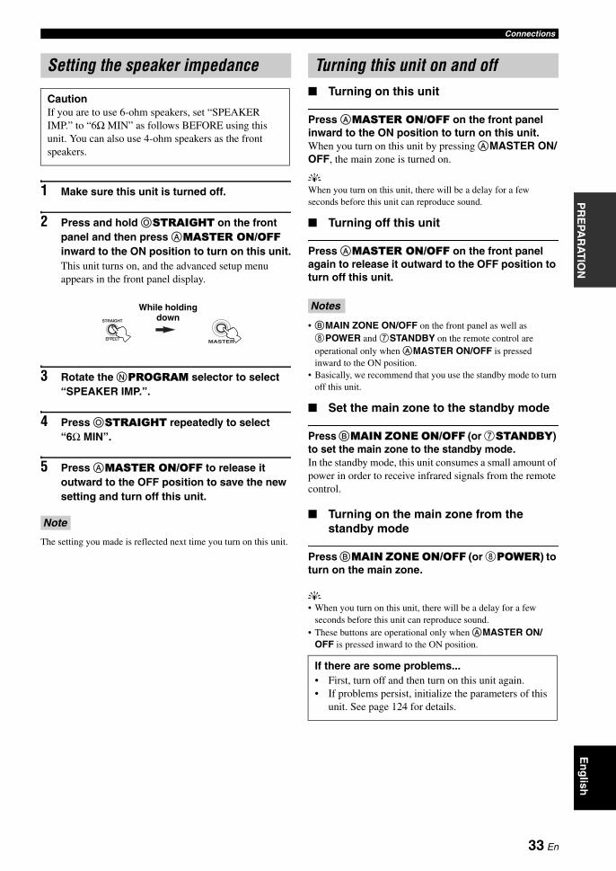
2 Press and hold OSTRAIGHT on the front panel and then press AMASTER ON/OFF inward to the ON position to turn on this unit.This unit turns on, and the advanced setup menu appears in the front panel display.
3 Rotate the NPROGRAM selector to select “SPEAKER IMP.”.
4 Press OSTRAIGHT repeatedly to select “6Ω MIN”.
5 Press AMASTER ON/OFF to release it outward to the OFF position to save the new setting and turn off this unit.
The setting you made is reflected next time you turn on this unit.
Turning on this unit
Press AMASTER ON/OFF on the front panel inward to the ON position to turn on this unit.When you turn on this unit by pressing AMASTER ON/OFF, the main zone is turned on.
yWhen you turn on this unit, there will be a delay for a few seconds before this unit can reproduce sound.
Turning off this unit
Press AMASTER ON/OFF on the front panel again to release it outward to the OFF position to turn off this unit.
• BMAIN ZONE ON/OFF on the front panel as well as 8POWER and 7STANDBY on the remote control are operational only when AMASTER ON/OFF is pressed inward to the ON position.
• Basically, we recommend that you use the standby mode to turn off this unit.
Set the main zone to the standby mode
Press BMAIN ZONE ON/OFF (or 7STANDBY) to set the main zone to the standby mode.In the standby mode, this unit consumes a small amount of power in order to receive infrared signals from the remote control.
Turning on the main zone from the standby mode
Press BMAIN ZONE ON/OFF (or 8POWER) to turn on the main zone.
y• When you turn on this unit, there will be a delay for a few
seconds before this unit can reproduce sound.• These buttons are operational only when AMASTER ON/
OFF is pressed inward to the ON position.
Setting the speaker impedance
CautionIf you are to use 6-ohm speakers, set “SPEAKER IMP.” to “6Ω MIN” as follows BEFORE using this unit. You can also use 4-ohm speakers as the front speakers.
Note
EFFECT
STRAIGHT
MASTER
While holding down
Turning this unit on and off
Notes
If there are some problems...• First, turn off and then turn on this unit again.• If problems persist, initialize the parameters of this
unit. See page 124 for details.
33 En

Connections
1 HDMI indicatorLights up when the signal of the selected input source is input at one of the HDMI input jacks (see page 21).
2 DOCK indicatorLights up when you station your iPod in a Yamaha iPod universal dock (such as the YDS-10, sold separately) connected to the DOCK terminal of this unit (see page 31).
3 Battery charge indicatorLights up when this unit charges the battery of the stationed iPod in the standby mode of this unit (see page 61).
4 Input source indicatorsThe corresponding cursor lights up to show the currently selected input source.
5 MUTE indicator and VOLUME level indicator• Indicates the current volume level.• The MUTE indicator flashes while the MUTE function
is on (see page 44).
6 Multi-information displayShows the name of the current sound field program and other information when adjusting or changing settings.
7 96/24 indicatorLights up when a DTS 96/24 signal is input to this unit.
8 Input channel and speaker indicators
Input channel indicators• Indicate the channel components of the current
digital input signal.• Light up or flash according to the settings of the
speakers when this unit is in the auto setup procedure (see page 37) or the speaker level setting procedure in the “SPEAKER LEVEL” (see page 79).
Presence speaker indicatorsLight up according to setting for “PRESENCE SP” (see page 78) in “SPEAKER SET” when this unit is in the auto setup procedure (see page 37) or the speaker level setting procedure in the “SPEAKER LEVEL” (see page 79).
yYou can make settings for the presence and surround back speakers automatically by running “AUTO SETUP” (see page 37) or manually by adjusting settings for “PRESENCE SP” (see page 78) and “SUR.B L/R SP” (see page 78) in “SPEAKER SET”.
Front panel display
MUTEVOLUMEdB
LL C RSL SB SR
DSDPCM
96/24
TUNED STEREOAUTO MEMORY
PSZONE2ZONE3
SLEEPPTY HOLD
PTYRTCT
EON
CD-R CD PHONO MULTI CH TUNERMD/TAPEBD/HD DVDDVDDOCK
DVR DTV/CBLVCRV-AUX
MASTER AUDIO
MATRIX DISCRETESILENT
CINEMAYPAO ENHANCERVIRTUAL HiFi DSP
HD 9624
q DIGITAL PLUS
q TRUE HDq EXq PL x LFE
SBRSBL
TUNED STEREOAUTO MEMORY
PSZONE2ZONE3
SLEEPPTY HOLD
PTYRTCT
EONBA
0
9876
5431 2
See page 35 for details.
Presence speaker indicators
Input channel indicators
LL C RSL SB SRLFE
SBRSBL
34 En

ConnectionsP
RE
PAR
AT
ION
En
glish
9 Tuner indicatorsLights up when this unit is in the FM or AM tuning mode.
TUNED indicatorLights up when this unit is tuned into a station (see page 54).
STEREO indicatorLights up when this unit is receiving a strong signal for an FM stereo broadcast while the AUTO indicator is lit (see page 54).
AUTO indicatorLights up when this unit is in the automatic tuning mode (see page 54).
MEMORY indicatorFlashes to show that a station can be stored (see page 55).
0 ZONE2/ZONE3 indicatorsLights up when Zone 2 or Zone 3 is turned on (see page 109).
A SLEEP indicatorLights up while the sleep timer is on (see page 45).
B Radio Data System indicators (Europe model only)
PTY HOLDLights up while searching for the Radio Data System stations in the PTY SEEK mode.
PS, PTY, RT and CTLight up according to the selected Radio Data System display mode.
EONLights up when the EON data service is being received.
C YPAO indicatorLights up when you run “AUTO SETUP” and when the speaker settings set in “AUTO SETUP” are used without any modifications (see page 37).
D Input signal indicatorsLights up when this unit is reproducing DSD (Direct Stream Digital) or PCM (Pulse Code Modulation) digital audio signals.
E DSP indicatorsThe respective indicator lights up when any of the sound field programs are selected.
CINEMA DSP indicatorLights up when you select a CINEMA DSP sound field program (see page 46).
HiFi DSP indicatorLights up when you select a HiFi DSP sound field program (see page 46).
VIRTUAL indicatorLights up when Virtual CINEMA DSP is active (see page 51).
F Sound field indicatorsLight up to indicate the active sound fields (see page 46).
G ENHANCER indicatorLights up when the Compressed Music Enhancer mode is turned on (see page 50).
H Headphones indicatorLights up when headphones are connected (see page 43).
I SILENT CINEMA indicatorLights up when headphones are connected and a sound field program is selected (see page 51).
J Decoder indicatorsThe respective indicator lights up when any of the decoders of this unit function.
DSDPCM
MASTER AUDIO
MATRIX DISCRETE
SILENT CINEMA
YPAO ENHANCER
HD 9624
q DIGITAL PLUS
q TRUE HDq EXq PL x
VIRTUAL HiFi DSPC
D
EFGHI
J
35 En

Connections
The remote control transmits a directional infrared ray.Be sure to aim the remote control directly at the remote control sensor on this unit during operation.
Display window (A)Shows the name of the selected input source that you can control.
Infrared window (P)Outputs infrared control signals. Aim this window at the component you want to operate.
Transmit indicator (O)Flashes while the remote control is sending infrared signals.
Operation mode selector (C)The function of some buttons depends on the operation mode selector position.
AMPOperates the amplifier function of this unit.
SOURCEOperates the component selected with an input selector button (see page 98).
TVOperates the TV assigned to either DTV/CBL or PHONO (see page 97).
• Do not spill water or other liquids on the remote control.• Do not drop the remote control.• Do not leave or store the remote control in the following
conditions:– places of high humidity, such as near a bath– places of high temperatures, such as near a heater or stove– places of extremely low temperatures– dusty places
• To set the remote control codes for other components, see page 99.
When you want to use the controls behind the front panel door, open the door by gently pressing on the lower part of the panel. Keep the door closed when not using these controls.
Using the remote control
30 30Approximately 6 m (20 ft)
Remote control sensor
Notes
Opening and closing the front panel door
To open, press gently on the lower part of the panel.
36 En

PR
EPA
RA
TIO
NE
ng
lish
This unit employs the YPAO (Yamaha Parametric Room Acoustic Optimizer) technology which lets you avoid troublesome listening-based speaker setup and achieves highly accurate sound adjustments automatically. The supplied optimizer microphone collects and this unit analyzes the sound your speakers produce in your actual listening environment.
• Be advised that it is normal for loud test tones to be output during the “AUTO SETUP” procedure.
• To achieve the best results, make sure the room is as quiet as possible while the “AUTO SETUP” procedure is in progress. If there is too much ambient noise, the results may not be satisfactory.
• We recommend that you get out of the room while this unit is in the automatic setup procedure. Keep quiet when you leave the room. It takes approximately 3 minutes for this unit to complete the automatic setup procedure.
y• The initial setting for each parameter is indicated in bold.• Before performing operations, set the operation mode selector
on the remote control to CAMP.
Basic procedure of the automatic setup
1 Make sure of the following check points before starting the AUTO SETUP operations. Speakers are connected appropriately. Headphones are disconnected from this unit. This unit and the video monitor are turned on. The connected subwoofer is turned on and the volume
level is set to about half way (or slightly less). The crossover frequency controls of the
connected subwoofer is set to the maximum. If you use the external amplifiers (see page 29),
the amplifiers are turned on and the settings are appropriate.
The room is sufficiently quiet.
2 Connect the supplied optimizer microphone to the OPTIMIZER MIC jack on the front panel.“MIC ON” and “View OSD Menu” appears in the front panel display.
The following menu screen appears on the video monitor.
yYou can also run “AUTO SETUP” using the system menu that appears in the front panel display. When you connect the optimizer microphone to the OPTIMIZER MIC jack, the following display appears in the front panel display. This manual uses the OSD illustrations to explain the “AUTO SETUP” procedure.
3 Place the optimizer microphone at your normal listening position on a flat level surface with the omni-directional microphone heading upward.
yIt is recommended that you use a tripod (etc.) to affix the optimizer microphone at the same height as your ears would be when you are seated in your listening position. You can use the attached screw of a tripod (etc.) to fix the optimizer microphone to the tripod (etc.).
Optimizing the speaker setting for your listening room
Using AUTO SETUP
Notes
SLEEP
ZONE ON/OFF ZONE CONTROLS
MULTI ZONE
MICOPTIMIZER
EFFECT
PROGRAM
YPAO
ZONE 3
RL OPTICAL
ZONE 2
AUDIO
VIDEO AUX
SILENT CINEMA S VIDEO VIDEO
PHONES
MODETUNING
PRESET/TUNING
EDIT
FM/AMTUNINGPRESET/
MAN'L/AUTO FMMEMORY
STRAIGHT
CONTROLSELECTAUDIO TONE
A/B/C/D/E
Omni-directional microphone
[]/[]:[ENTER]:
[ p
AUTO SETUP
SETUP;;;;;;;;;AUTOWIRING;;;;;;;CHECKDISTANCE;;;;;CHECKSIZE;;;;;;;;;CHECKEQ;;;;;;;;;NATURALLEVEL;;;;;;;;CHECKSTART
UP/DOWNStart
.
A U T O S E T U P
E N T E R T O S T A R T
Optimizer microphone
37 En

Optimizing the speaker setting for your listening room
4 Press 3ENTER to start the setup procedure.This unit starts the automatic setup procedure. Loud test tones are output from each speaker during the automatic setup procedure. Once all items are set, the result display appears in the OSD.
• During the automatic setup procedure, do not perform any operation on this unit. If you perform any operation while this unit is in the automatic setup procedure, “E-9:USER CANCEL” appears in the OSD. In such cases, select “RETRY” to restart the automatic setup procedure.
• We recommend that you get out of the room while this unit is in the automatic setup procedure. Keep quiet when you leave the room. It takes approximately 3 minutes for this unit to complete the automatic setup procedure.
The display changes as follows.
The results displayed under “RESULT” are as follows.
Number of speakers SP
Displays the number of speakers connected to this unit in the following order:Front/Back/Subwoofer
Speaker distance DIST
Displays the speaker distance from the listening position in the following order:Closest speaker distance/Farthest speaker distance
Speaker level LVL
Displays the speaker output level in the following order:Lowest speaker output level/Highest speaker output level
• If “E-10:INTERNAL ERROR” appears during the testing procedure, restart from step 2.
• If an error occurs during the automatic setup procedure, the setup procedure is canceled and an error screen appears. For details, see “If an error screen appears” on page 41.
• When this unit detects potential problems during the automatic setup procedure, “WARNING” and the number of warning messages appears in the above of “RESULT” (see page 41).
• Depending on the listening environment, “SWFR PHASE:REV” appears during the automatic setup procedure and “SUBWOOFER PHASE” in “SOUND MENU” (see page 79) is automatically set to “REVERSE”.
5 Press 3ENTER to display the setup results in detail.
Notes
[ ] :[
AUTO SETUP
INITIALIZINGPRE CHECKMAIN CHECKEQUALIZINGLEVEL
||||||||;;;;;;;;;;EXIT
.
[]/[]:[ENTER]:
[ p
AUTO SETUP
SETUP;;;;;;;;;AUTOWIRING;;;;;;;CHECKDISTANCE;;;;;CHECKSIZE;;;;;;;;;CHECKEQ;;;;;;;;;NATURALLEVEL;;;;;;;;CHECKSTART
UP/DOWNStart
.
[]/[]:[ENTER]:
[ p
AUTO SETUP
RESULTSP : 5/4/0.1DIST: 3.60/4.30mLVL : -10.0/+5.0dB>SET CANCEL
UP/DOWNDetail
.
Notes
[]/[]:[ENTER]:
[ p
AUTO SETUP
RESULTSP : 5/4/0.1DIST: 3.60/4.30mLVL : -10.0/+5.0dB>SET CANCEL
UP/DOWNDetail
.
[p]/[[]:[ENTER]:
RESULT WIRING
FRONT L;;;;;OK
SelectReturn
38 En

Optimizing the speaker setting for your listening roomP
RE
PAR
AT
ION
En
glish
6 Press 3l / h repeatedly to toggle between the setup result displays.
y• Press 3k / n to toggle between the parameters in a
results.• If you are not satisfied with the results or want to manually
adjust each parameter, run “MANUAL SETUP” (see page 72).
• If you change speakers, speaker positions, or the layout of your listening environment, run “AUTO SETUP” again to recalibrate your system.
• The distances displayed in the “DISTANCE” results may be longer than the actual distance depending on the characteristics of your subwoofer or external amplifiers if you connect them.
• In the “EQUALIZING” results, different values may be set for the same band to provide finer adjustments.
7 Press 3ENTER to return to the top result display.
8 Press 3l / h to select “SET” or “CANCEL”.
Choices: SET, CANCEL• Select “SET” to confirm the “AUTO SETUP”
results.• Select “CANCEL” to cancel the “AUTO SETUP”
results.
9 Press 3ENTER to confirm your selection.The top “SET MENU” display appears in the OSD.
10 Press FSET MENU to exit from “SET MENU”.
• After you have completed the automatic setup procedure, be sure to disconnect the optimizer microphone.
• The optimizer microphone is sensitive to heat. Keep it away from direct sunlight and do not place it on top of this unit.
Notes
Results of the speaker connection and wiring
Results of the speaker distance from the listening position
Result of the speaker detection and size
Results of the parametric equalizer of each speaker
Results of the speaker output level
[]/[]:[ENTER]:
[ p
AUTO SETUP
RESULTSP : 5/4/0.1DIST: 3.60/4.30mLVL : -10.0/+5.0dB>SET CANCEL
UP/DOWNEnter
.
Notes
SYSTEM MEMORY featureYou can save multiple result of the automatic setup by using the SYSTEM MEMORY feature. See page 93 for details.
[]/[]:[ENTER]:
[ p
AUTO SETUP
RESULTSP : 5/4/0.1DIST: 3.60/4.30mLVL : -10.0/+5.0dB>SET CANCEL
UP/DOWNEnter
.
[]/[]:[ENTER]:
[ p
SET MENU
;AUTO SETUP;MANUAL SETUP;SYSTEM MEMORY;SIGNAL INFO
UP/DOWNEnter
.
39 En

Optimizing the speaker setting for your listening room
Customizing the measurements You can select the parametric equalizer type, and activate or deactivate each check items.
1 Connect the supplied optimizer microphone to this unit and place the microphone appropriately.Refer to the steps 1 to 3 of “Basic procedure of the automatic setup” on page 37.
2 Press 3k repeatedly to select “SETUP” and then press 3l / h to select the desired setting.
Choices: AUTO, RELOAD• Select “AUTO” to automatically run the entire
“AUTO SETUP” procedure.• Select “RELOAD” to reload the last “AUTO
SETUP” settings and override the current settings. When you select “RELOAD”, the previous auto setup result appears in the OSD. See step 4 on page 38 and carry out the operations.
• “RELOAD” is available only when you have previously run “AUTO SETUP” and confirmed the results.
• If you selected “RELOAD” in step 2, no test tones are output and the result of the previous automatic setup appears in the OSD.
3 Press 3k / n repeatedly to select “WIRING”, “DISTANCE”, “SIZE”, “EQ”, or “LEVEL” and then press 3l / h to select the desired setting.This unit performs the following checks:
Speaker wiring WIRING
Checks which speakers are connected and the polarity of each speaker.
Speaker distance DISTANCEChecks the distance of each speaker from the listening position and adjusts the timing of each channel.
Speaker size SIZEChecks the frequency response of each speaker and sets the appropriate low-frequency crossover for each channel.
Choices: CHECK, SKIP• Select “CHECK” to automatically check and adjust
the item.• Select “SKIP” to skip the item and perform no
adjustments.
Parametric equalizer type EQParametric equalizer adjusts the level of the specified frequency bands. This unit automatically selects the crucial frequency bands for the listening room and adjusts the level of the selected frequency bands to create a cohesive sound field in the room. You can select the type of the parametric equalizer adjustment from the following choices.Choices: NATURAL, FLAT, FRONT, SKIP• Select “NATURAL” to average out the frequency
response of all speakers with higher frequencies being less emphasized. Recommended if the FLAT setting sounds a little harsh.
• Select “FLAT” to average the frequency response of all speakers. Recommended if all of your speakers are of similar quality.
• Select “FRONT” to adjust the frequency response of each speaker in accordance with the sound of your front speakers. Recommended if your front speakers are of much higher quality than your other speakers.
• Select “SKIP” to skip this item and perform no adjustments.
Volume level LEVELChecks and adjusts the volume level of each speaker.Choices: CHECK, SKIP• Select “CHECK” to automatically check and adjust
this item.• Select “SKIP” to skip this item and perform no
adjustments.
4 After the setting of the measurement, start the automatic setup procedure.Refer to steps 4 to 6 of “Basic procedure of the automatic setup” on page 38 for details.
Notes
SYSTEM MEMORY featureYou can save multiple result of the automatic setup by using the SYSTEM MEMORY feature. See page 93 for details.
40 En

Optimizing the speaker setting for your listening roomP
RE
PAR
AT
ION
En
glish
If an error screen appears
Press 3l / h to select “RETRY” or “EXIT” and then press 3ENTER.The following display is an example where “E-9:USER CANCEL” appears in the OSD.
Choices: RETRY, EXIT• Select “RETRY” to retry the “AUTO SETUP”
procedure.• Select “EXIT” to exit from the “AUTO SETUP”
procedure.
y• If “E-5:NOISY” appears in the OSD, you can also select
“PROCEED” and let this unit continue the automatic setup. However, we recommend that you perform the automatic setup procedure again for more accurate adjustment.
• If “E-10:INTERNAL ERROR” appears in the OSD, you can select only “EXIT”.
• For details about each error message, refer to the “AUTO SETUP” section in “Troubleshooting” on page 123.
If “WARNING” appearsWhen this unit detects potential problems during the automatic setup procedure, “WARNING” appears in the result display. Check the warning messages to correct your speaker settings.
Warnings differ from errors in that warnings do not cancel the “AUTO SETUP” procedure.
1 Make sure the pointer is pointing at “WARNING” and then press 3ENTER to display the detailed information about the warning.The number on the right of “WARNING” indicates the number of warning messages.
2 Press 3l / h repeatedly to toggle between the warning displays.
y• For details about each warning message, refer to the
“AUTO SETUP” section in “Troubleshooting” on page 123.
• When the corresponding warning message is not applicable to a speaker, “–––” is displayed instead.
• If the volume level setting of the connected subwoofer is too high or low, “TOO LOUD” (the volume level setting is too high) or “TOO LOW” (the volume level setting is too low) is displayed in the “W-3:LEVEL ERROR” display. Adjust the volume level setting of the connected subwoofer appropriately.
3 Press 3ENTER to return to the top result display.
yThe adjustment are made even if “WARNING” appears, however the adjustment may not be optimal.
Note
[p]/[[]:[ENTER]:
ERROR
E-9:USER CANCELDon't operateany function
>RETRY EXIT
SelectEnter
.
[p]/[[]:[ENTER]:
ERROR
E-5:NOISYKeep silent
>RETRY EXIT PROCEED
SelectEnter
.
[]/[]:[ENTER]:
[ p
AUTO SETUP
WARNING 2RESULTSP : 5/4/0.1DIST: 3.60/4.30mLVL : -10.0/+5.0dB>SET CANCEL
UP/DOWNDetail
.
[p]/[[]:[ENTER]:
WARNING
W-1:OUT OF PHASEReverse channel
FL ---CENTER--- PRSL ---SBL ---
SelectReturn
[p]/[[]:[ENTER]:
WARNING
W-3:LEVEL ERROR--- FRCENTERPL ------ SR--- SBLSWFR:TOO LOUD
SelectReturn
41 En

1 Turn on the video monitor connected to this unit.
y• See page 44 to display the input source information.• You can display a gray background in the OSD when there
is no video signal being input by setting “GRAY BACK” in “OPTION MENU” to “AUTO” (see page 88).
• You can turn on or off the short message displays on the video monitor. See pages 88 for details.
2 Rotate the CINPUT selector (or set the operation mode selector to CAMP and then press one of the input selector buttons (1)) to select the desired input source.
The name of the currently selected input source appears in the front panel display and in the OSD for a few seconds.
3 Start playback on the selected source component or select a broadcast station.• Refer to the instruction manuals for the source
component.• See page 54 for details about FM/AM tuning
instructions.
4 Rotate QVOLUME (or press BVOLUME +/–) to adjust the volume to the desired output level.Control range: MUTE, –80.0 dB (minimum) to
+16.5 dB (maximum)
ySee page 53 to adjust the level of each speaker.
5 Rotate the NPROGRAM selector (or press one of the sound field program selector buttons (N) repeatedly) to select the desired sound field program.The name of the selected sound field program appears in the front panel display and in the OSD. See page 46 for details about sound field programs.
Sound field programs cannot be selected when the component connected to the MULTI CH INPUT jacks is selected as the input source (see page 43).
y• Choose a sound field program based on your listening
preference, not merely on the name of the program.• When you select an input source, this unit automatically selects
the last sound field program used with the corresponding input source.
• To display information about the currently selected input source in the OSD, see page 44 for details.
Playback
CautionExtreme caution should be exercised when you play back CDs encoded in DTS. If you play back a CD encoded in DTS on a DTS-incompatible CD player, you will only hear some unwanted noise that may damage your speakers. Check whether your CD player supports CDs encoded in DTS. Also, check the sound output level of your CD player before you play back a CD encoded in DTS.
yTo play DTS-encoded CDs when using a digital audio connection, set “DECODER MODE” in “INPUT MENU” to “DTS” before the playback (see page 86).
Before performing the following operations, set the operation mode selector on the remote control to CAMP.
Basic procedure
CD-R CD PHONO MULTI CH TUNERMD/TAPEBD/HD DVDDVDDVR DTV/CBLVCRV-AUX
B D / H D D V D
Currently selected inputsource
Available input sources
Note
M o v i e
S c i - F i
Currently selected sound field program
Currently selected sound field program category
42 En
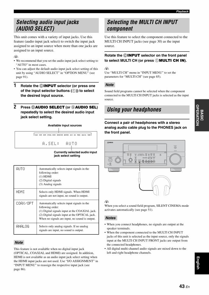
PlaybackB
AS
IC
OP
ER
AT
ION
En
glish
This unit comes with a variety of input jacks. Use this feature (audio input jack select) to switch the input jack assigned to an input source when more than one jacks are assigned to an input source.
y• We recommend that you set the audio input jack select setting to
“AUTO” in most cases.• You can adjust the default audio input jack select setting of this
unit by using “AUDIO SELECT” in “OPTION MENU” (see page 91).
1 Rotate the CINPUT selector (or press one of the input selector buttons (1)) to select the desired input source.
2 Press DAUDIO SELECT (or 9AUDIO SEL) repeatedly to select the desired audio input jack select setting.
This feature is not available when no digital input jack (OPTICAL, COAXIAL and HDMI) are assigned. In addition, HDMI is not available as an audio input jack select setting when the HDMI input jacks are not used. Use “I/O ASSIGNMENT” in “INPUT MENU” to reassign the respective input jack (see page 86).
Use this feature to select the component connected to the MULTI CH INPUT jacks (see page 30) as the input source.
Rotate the CINPUT selector on the front panel to select MULTI CH (or press 1MULTI CH IN).
yUse “MULTI CH” menu in “INPUT MENU” to set the parameters for “MULTI CH” (see page 85).
Sound field programs cannot be selected when the component connected to the MULTI CH INPUT jacks is selected as the input source.
Connect a pair of headphones with a stereo analog audio cable plug to the PHONES jack on the front panel.
yWhen you select a sound field program, SILENT CINEMA mode activates automatically (see page 51).
• When you connect headphones, no signals are output at the speaker terminals.
• When the component connected to the MULTI CH INPUT jacks of this unit is selected as the input source, only the signals input at the MULTI CH INPUT FRONT jacks are output from the connected headphones.
• All digital multi-channel audio signals are mixed down to the left and right headphone channels.
Selecting audio input jacks (AUDIO SELECT)
AUTO Automatically selects input signals in the following order:(1) HDMI(2) Digital signals(3) Analog signals
HDMI Selects only HDMI signals. When HDMI signals are not input, no sound is output.
COAX/OPT Automatically selects input signals in the following order:(1) Digital signals input at the COAXIAL jack.(2) Digital signals input at the OPTICAL jack.When no signals are input, no sound is output.
ANALOG Selects only analog signals. If no analog signals are input, no sound is output.
Note
CD-R CD PHONO MULTI CH TUNERMD/TAPEBD/HD DVDDVDDVR DTV/CBLVCRV-AUX
A . S E L : A U T O
Currently selected audio input jack select setting
Available input sources
Selecting the MULTI CH INPUT component
Note
Using your headphones
Notes
MASTER
PURE DIRECT
VOLUME
MAIN ZONE
INPUT
OFFON
SLEEP
ZONE ON/OFF ZONE CONTROLS
MULTI ZONE
MICOPTIMIZER
EFFECT
PROGRAM
YPAO
ZONE 3
RL OPTICAL
ZONE 2
AUDIO
VIDEO AUX
SILENT CINEMA S VIDEO VIDEO
PHONES
MODETUNING
PRESET/TUNING
EDIT
FM/AMTUNINGPRESET/
MAN'L/AUTO FMMEMORY
STRAIGHT
CONTROLSELECTAUDIO TONE
A/B/C/D/E
ON/OFF
43 En
Playback
Press DMUTE on the remote control to mute the audio output. Press DMUTE again to resume the audio output.
y• You can also rotate QVOLUME on the front panel or press BVOLUME +/– on the remote control to resume the audio output.
• You can adjust the muting level by using the “MUTING TYPE” parameter in “VOLUME MENU” (see page 81).
• The MUTE indicator flashes in the front panel display when the audio output is muted and disappears from the front panel display when the audio output is resumed.
You can display the format, sampling frequency, channel, bit rate and flag data of the current input signal.
1 Set the operation mode selector to CAMP and then press FSET MENU on the remote control.The top “SET MENU” display appears in the OSD.
2 Press 3n repeatedly to select “SIGNAL INFO” and then press 3ENTER.The audio information about the input source appears in the OSD.
3 Press 3l / h to toggle between the audio and video information displays.
yThe information is also appears in the front panel display. Press 3k / n repeatedly to change the displayed information.
4 Press FSET MENU on the remote control again to exit from “SET MENU”.
Audio information
• “–––” appears when this unit cannot display the corresponding information.
• Some high definition audio bitstream contents may not include the discrete surround back left and right channel signals but are encoded at the bitrate of 192 kHz.
• Even if you make settings to output bitstreames directly, some players convert the Dolby TrueHD or Dolby Digital Plus bitstreams to the Dolby Digital bitstreams, while converting the DTS-HD Master Audio or DTS-HD High Resolution Audio bitstreams to the DTS bitstreams.
Video information
“–––” appears when this unit cannot display the corresponding information.
Muting the audio output
Displaying the input source information (SIGNAL INFO)
[]/[]:[ENTER]:
[ p
SET MENU
;AUTO SETUP;MANUAL SETUP;SYSTEM MEMORY;SIGNAL INFO
UP/DOWNEnter
.
FORMAT Signal format. When this unit cannot detect a digital signal, it automatically switches to analog input.
SAMPLING The number of samples per second taken from a continuous signal to make a discrete signal.
CHANNEL The number of source channels in the input signal (front/surround/LFE). For example, a multi-channel soundtrack with 3 front channels, 2 surround channels and LFE, is displayed as “3/2/0.1”.
BITRATE The number of bits passing a given point per second.
DIALOG The dialogue normalization level preset to the current input bitstream signal (see page 125).
FLAG Flag data encoded in the bitstream, or PCM signals that cue this unit to automatically switch decoders (“Surround EX”, etc.).
Notes
HDMI SIGNAL Type of the source video signals and the video signals output at the HDMI OUT jack of this unit.
HDMI RES. Resolution of the input signal (analog or HDMI) and the output signal (HDMI).
ANALOG RES. Resolution of the source video signals and the analog video signals output at the COMPONENT MONITOR OUT jacks of this unit.
HDMI ERROR(HDMI MESSAGE)
Error message for HDMI sources or connected HDMI devices. See page 120 for details.
Note
44 En
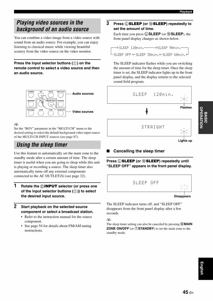
PlaybackB
AS
IC
OP
ER
AT
ION
En
glish
You can combine a video image from a video source with sound from an audio source. For example, you can enjoy listening to classical music while viewing beautiful scenery from the video source on the video monitor.
Press the input selector buttons (1) on the remote control to select a video source and then an audio source.
ySet the “BGV” parameter in the “MULTI CH” menu to the desired setting to select the default background video input source of the MULTI CH INPUT sources (see page 87).
Use this feature to automatically set the main zone to the standby mode after a certain amount of time. The sleep timer is useful when you are going to sleep while this unit is playing or recording a source. The sleep timer also automatically turns off any external components connected to the AC OUTLET(S) (see page 32).
1 Rotate the CINPUT selector (or press one of the input selector buttons (1)) to select the desired input source.
2 Start playback on the selected source component or select a broadcast station.• Refer to the instruction manual for the source
component.• See page 54 for details about FM/AM tuning
instructions.
3 Press LSLEEP (or 0SLEEP) repeatedly to set the amount of time.Each time you press LSLEEP (or 0SLEEP), the front panel display changes as shown below.
The SLEEP indicator flashes while you are switching the amount of time for the sleep timer. Once the sleep timer is set, the SLEEP indicator lights up in the front panel display, and the display returns to the selected sound field program.
Cancelling the sleep timer
Press LSLEEP (or 0SLEEP) repeatedly until “SLEEP OFF” appears in the front panel display.
The SLEEP indicator turns off, and “SLEEP OFF” disappears from the front panel display after a few seconds.
yThe sleep timer setting can also be canceled by pressing BMAIN ZONE ON/OFF (or 7STANDBY) to set the main zone to the standby mode.
Playing video sources in the background of an audio source
Using the sleep timer
DTV/CBL VCRDVR V-AUX/DOCK
TUNER CD CD-R MULTI CH IN
DVD BD/HD DVD PHONOMD/TAPE
Audio sources
Video sources
SLEEP 120min. SLEEP 90min.
SLEEP 60min.SLEEP 30min.SLEEP OFF
SLEEP
S L E E P 1 2 0 m i n .
Flashes
SLEEP
S T R A I G H T
Lights up
S L E E P O F F
Disappears
45 En
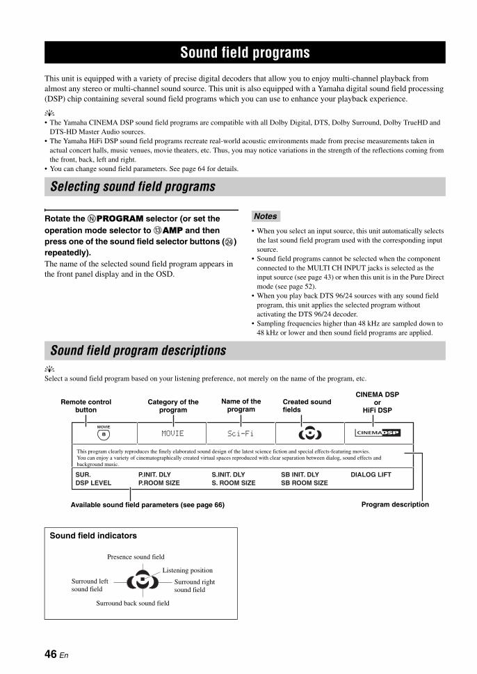
This unit is equipped with a variety of precise digital decoders that allow you to enjoy multi-channel playback from almost any stereo or multi-channel sound source. This unit is also equipped with a Yamaha digital sound field processing (DSP) chip containing several sound field programs which you can use to enhance your playback experience.
y• The Yamaha CINEMA DSP sound field programs are compatible with all Dolby Digital, DTS, Dolby Surround, Dolby TrueHD and
DTS-HD Master Audio sources.• The Yamaha HiFi DSP sound field programs recreate real-world acoustic environments made from precise measurements taken in
actual concert halls, music venues, movie theaters, etc. Thus, you may notice variations in the strength of the reflections coming from the front, back, left and right.
• You can change sound field parameters. See page 64 for details.
Rotate the NPROGRAM selector (or set the operation mode selector to CAMP and then press one of the sound field selector buttons (N) repeatedly).The name of the selected sound field program appears in the front panel display and in the OSD.
• When you select an input source, this unit automatically selects the last sound field program used with the corresponding input source.
• Sound field programs cannot be selected when the component connected to the MULTI CH INPUT jacks is selected as the input source (see page 43) or when this unit is in the Pure Direct mode (see page 52).
• When you play back DTS 96/24 sources with any sound field program, this unit applies the selected program without activating the DTS 96/24 decoder.
• Sampling frequencies higher than 48 kHz are sampled down to 48 kHz or lower and then sound field programs are applied.
ySelect a sound field program based on your listening preference, not merely on the name of the program, etc.
Sound field programs
Selecting sound field programs
Notes
Sound field program descriptions
Sound field indicators
DIALOG LIFTSB ROOM SIZES. ROOM SIZESB INIT. DLYS.INIT. DLY
P.ROOM SIZE
Sci-FiMOVIE
P.INIT. DLYSUR.DSP LEVEL
8
MOVIE
This program clearly reproduces the finely elaborated sound design of the latest science fiction and special effects-featuring movies. You can enjoy a variety of cinematographically created virtual spaces reproduced with clear separation between dialog, sound effects and background music.
Available sound field parameters (see page 66) Program description
Remote control button
Name of the program
Created sound fields
CINEMA DSP or
HiFi DSPCategory of the
program
Presence sound field
Listening position
Surround left sound field
Surround right sound field
Surround back sound field
46 En
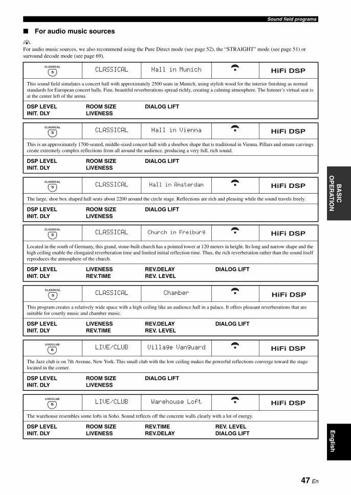
Sound field programsB
AS
IC
OP
ER
AT
ION
En
glish
For audio music sources
yFor audio music sources, we also recommend using the Pure Direct mode (see page 52), the “STRAIGHT” mode (see page 51) or surround decode mode (see page 69).
CLASSICAL Hall in Munich
This sound field simulates a concert hall with approximately 2500 seats in Munich, using stylish wood for the interior finishing as normal standards for European concert halls. Fine, beautiful reverberations spread richly, creating a calming atmosphere. The listener’s virtual seat is at the center left of the arena.
DSP LEVELINIT. DLY
ROOM SIZELIVENESS
DIALOG LIFT
CLASSICAL Hall in Vienna
This is an approximately 1700-seated, middle-sized concert hall with a shoebox shape that is traditional in Vienna. Pillars and ornate carvings create extremely complex reflections from all around the audience, producing a very full, rich sound.
DSP LEVELINIT. DLY
ROOM SIZELIVENESS
DIALOG LIFT
7
ENTERTAIN
5
CLASSICAL
HiFi DSP
7
ENTERTAIN
5
CLASSICAL
HiFi DSP
CLASSICAL Hall in Amsterdam
The large, shoe box shaped hall seats about 2200 around the circle stage. Reflections are rich and pleasing while the sound travels freely.
DSP LEVELINIT. DLY
ROOM SIZELIVENESS
DIALOG LIFT
CLASSICAL Church in Freiburg
Located in the south of Germany, this grand, stone-built church has a pointed tower at 120 meters in height. Its long and narrow shape and the high ceiling enable the elongated reverberation time and limited initial reflection time. Thus, the rich reverberation rather than the sound itself reproduces the atmosphere of the church.
DSP LEVELINIT. DLY
LIVENESSREV.TIME
REV.DELAYREV. LEVEL
DIALOG LIFT
CLASSICAL Chamber
This program creates a relatively wide space with a high ceiling like an audience hall in a palace. It offers pleasant reverberations that are suitable for courtly music and chamber music.
DSP LEVELINIT. DLY
LIVENESSREV.TIME
REV.DELAYREV. LEVEL
DIALOG LIFT
LIVE/CLUB Village Vanguard
The Jazz club is on 7th Avenue, New York. This small club with the low ceiling makes the powerful reflections converge toward the stage located in the corner.
DSP LEVELINIT. DLY
ROOM SIZELIVENESS
DIALOG LIFT
LIVE/CLUB Warehouse Loft
The warehouse resembles some lofts in Soho. Sound reflects off the concrete walls clearly with a lot of energy.
DSP LEVELINIT. DLY
ROOM SIZELIVENESS
REV.TIMEREV.DELAY
REV. LEVELDIALOG LIFT
7
ENTERTAIN
5
CLASSICAL
HiFi DSP
7
ENTERTAIN
5
CLASSICAL
HiFi DSP
5
CLASSICAL
HiFi DSP
6
LIVE/CLUB
HiFi DSP
6
LIVE/CLUB
HiFi DSP
47 En

Sound field programs
For various sources
The available sound field parameters and the created sound fields differ depending on the input sources and the settings of this unit.
LIVE/CLUB Cellar Club
This program simulates a live house with a low ceiling and homey atmosphere. A realistic, live sound field features powerful sound as if the listener is in a row in front of a small stage.
DSP LEVELINIT. DLY
ROOM SIZELIVENESS
DIALOG LIFT
LIVE/CLUB The Roxy Theatre
This is the sound field of a rock music live house in Los Angeles, with approximately 460 seats. The listener’s virtual seat is at the center left of the hall.
DSP LEVELINIT. DLY
ROOM SIZELIVENESS
REV.TIMEREV.DELAY
REV. LEVELDIALOG LIFT
LIVE/CLUB The Bottom Line
This is the sound field at stage front in The Bottom Line, a famous New York jazz club. The floor can seat 300 people to the left and right in a sound field offering real and vibrant sound.
DSP LEVELINIT. DLY
ROOM SIZELIVENESS
DIALOG LIFT
Note
ENTERTAINMENT Sports
This program allows the listeners to enjoy stereo sport broadcasts and studio variety programs with enriched live feeling. In sports broadcasts, the voices of the commentator and sportscaster are positioned clearly on the center while the atmosphere of the stadium expands in an optimum space to offer the listeners with a feeling of presence in the stadium.
DSP LEVELP. INIT. DLY
P. ROOM SIZES. INIT. DLY
S. ROOM SIZESB INIT. DLY
SB ROOM SIZEDIALOG LIFT
ENTERTAINMENT Action Game
This sound field is suitable for action games such as car racing and FPS games. It uses the reflection data that limits the effects range per channel in order to offer a powerful playing environment with a being-there feeling by enhancing various effects tones while maintaining a clear sense of directions.
DSP LEVELP. INIT. DLY
P. ROOM SIZES. INIT. DLY
S. ROOM SIZESB INIT. DLY
SB ROOM SIZEDIALOG LIFT
ENTERTAINMENT Roleplaying Game
This sound field is suitable for role-playing and adventure games. It combines the sound field effects for movies and the sound field design used with “Action Game” to represent the depth and 3D feeling of the field during play, while offering movie-like surround effects in the movie scenes in the game.
DSP LEVELP. INIT. DLY
P. ROOM SIZES. INIT. DLY
S. ROOM SIZESB INIT. DLY
SB ROOM SIZEDIALOG LIFT
6
LIVE/CLUB
HiFi DSP
6
LIVE/CLUB
HiFi DSP
6
LIVE/CLUB
HiFi DSP
7
ENTERTAIN
7
ENTERTAIN
7
ENTERTAIN
48 En

Sound field programsB
AS
IC
OP
ER
AT
ION
En
glish
For visual sources of music
The available sound field parameters and the created sound fields differ depending on the input sources and the settings of this unit.
For movie sources
yYou can select the desired decoder (SUR.) used with following sound field program (except “Mono Movie”). See page 71 for details.
The available sound field parameters and the created sound fields differ depending on the input sources and the settings of this unit.
Note
ENTERTAINMENT Music Video
This sound field offers an image of a concert hall for live performance of pop, rock and jazz music. The listener can indulge oneself in a hot live space thanks to the presence sound field that emphasizes the vividness of vocals and solo play and the beat of rhythm instruments, and to the surround sound field that reproduces the space of a big live hall.
DSP LEVELP. INIT. DLY
P. ROOM SIZES. INIT. DLY
S. ROOM SIZESB INIT. DLY
SB ROOM SIZEDIALOG LIFT
ENTERTAINMENT Recital/Opera
This program controls the amount of reverberations at an optimum level and emphasizes the depth and clarity of human voices. “Opera” offers the reverberations of an orchestra box in front of the listener at the same time as providing the acoustic positioning and feeling of presence on the stage. The surround sound field is relatively moderate, but the data for concert hall effects are used to represent the inherent beauty of music. The listener will not be fatigued even after long hours of opera entertainment.
DSP LEVELP. INIT. DLY
P. ROOM SIZES. INIT. DLY
S. ROOM SIZESB INIT. DLY
SB ROOM SIZEDIALOG LIFT
Note
6
LIVE/CLUB
7
ENTERTAIN
HiFi DSP
7
ENTERTAIN
MOVIE Standard
This program creates a sound field emphasizing the surrounding feeling without disturbing the original acoustic positioning of multi-channel audio such as Dolby Digital and DTS. It has been designed with the concept of “an ideal movie theater”, in which the audience is surrounded by beautiful reverberations from the left, right and rear.
SUR.DSP LEVEL
S. INIT. DLYS. ROOM SIZE
S. LIVENESSSB INIT. DLY
SB ROOM SIZESB LIVENESS
DIALOG LIFT
MOVIE Spectacle
This program represents the spectacular feeling of large-scale movie productions. It reproduces a broad theater sound field matching the cinemascope and wider-screen movies with an excellent dynamic range from very small to extremely large sound.
SUR.DSP LEVEL
P. INIT. DLYP. ROOM SIZE
S. INIT. DLYS. ROOM SIZE
SB INIT. DLYSB ROOM SIZE
DIALOG LIFT
8
MOVIE
8
MOVIE
MOVIE Sci-Fi
This program clearly reproduces the finely elaborated sound design of the latest science fiction and special effects-featuring movies. You can enjoy a variety of cinematographically created virtual spaces reproduced with clear separation between dialog, sound effects and background music.
SUR.DSP LEVEL
P. INIT. DLYP. ROOM SIZE
S. INIT. DLYS. ROOM SIZE
SB INIT. DLYSB ROOM SIZE
DIALOG LIFT
8
MOVIE
49 En

Sound field programs
Stereo playback
Compressed Music Enhancer
MOVIE Adventure
This program is ideal for precisely reproducing the sound design of action and adventure movies.The sound field restrains reverberations but puts emphasis on reproducing a powerful space expanded widely to the left and right. The reproduced depth is also restrained relatively to ensure the separation between audio channels and the clarity of the sound.
SUR.DSP LEVEL
P. INIT. DLYP. ROOM SIZE
S. INIT. DLYS. ROOM SIZE
SB INIT. DLYSB ROOM SIZE
DIALOG LIFT
8
MOVIE
MOVIE Drama
This sound field features stable reverberations that match a wide range of movie genres from serious dramas to musicals and comedies. The reverberations are modest but offer an optimum 3D feeling, reproducing effects tones and background music softly but cubically around clear words and center positioning in a way that does not fatigue the listener even after long hours of viewing.
SUR.DSP LEVEL
P. INIT. DLYP. ROOM SIZE
S. INIT. DLYS. ROOM SIZE
SB INIT. DLYSB ROOM SIZE
DIALOG LIFT
8
MOVIE
MOVIE Mono Movie
This program is provided for reproducing monaural video sources such as a classic movie in an atmosphere of a good old movie theater.The program produces the optimum expansion and reverberation to the original audio to create a comfortable space with a certain sound depth.
DSP LEVELINIT. DLY
ROOM SIZELIVENESS
REV.TIMEREV. LEVEL
REV.DELAYDIALOG LIFT
STEREO 2ch Stereo
Use this program to mix down multi-channel sources to 2 channels. See page 53 for details.
DIRECT
8
MOVIE
9
STEREO
STEREO 7ch Stereo
Use this program to output sound from all speakers. When you play back multi-channel sources, this unit downmixes the source to 2 channels, and then output the sound from all speakers. This program creates a larger sound field and is ideal for background music at parties, etc.
CT LEVELSL LEVEL
SR LEVELSB LEVEL
PL LEVELPR LEVEL
MUSIC ENHANCER Straight Enhancer
Use this program to enhance the sound nearest to the original depth and width of the 2-channel or multi-channel compression artifacts.
EFFECT LEVEL
9
STEREO
HiFi DSP
6
ENHANCER
MUSIC ENHANCER 7ch Enhancer
Use this program to play back compression artifacts in 7-channel stereo.
EFFECT LEVEL
6
ENHANCER
50 En
Sound field programsB
AS
IC
OP
ER
AT
ION
En
glish
Using sound field programs without surround speakers (Virtual CINEMA DSP)
Virtual CINEMA DSP allows you to enjoy the CINEMA DSP or HiFi DSP sound field programs without surround speakers. It creates virtual speakers to reproduce the natural sound field.When you set “SUR. L/R SP” to “NONE” (see page 78), Virtual CINEMA DSP activates automatically whenever you select a CINEMA DSP or HiFi DSP sound field program (see page 46).
Virtual CINEMA DSP will not activate even when “SUR. L/R SP” is set to “NONE” (see page 78) in the following cases:
– when the component connected to the MULTI CH INPUT jacks is selected as the input source (see page 43).
– when headphones are connected to the PHONES jack.– when this unit is in the “7ch Stereo” mode.
Enjoying multi-channel sources and sound field programs with headphones (SILENT CINEMA)
SILENT CINEMA allows you to enjoy multi-channel music or movie sound through ordinary headphones. SILENT CINEMA activates automatically whenever you connect headphones to the PHONES jack while listening to CINEMA DSP or HiFi DSP sound field programs (see page 46). When activated, the SILENT CINEMA indicator lights up in the front panel display.
• SILENT CINEMA does not activate when the component connected to the MULTI CH INPUT jacks is selected as the input source (see page 43).
• SILENT CINEMA is not effective when the Pure Direct (see page 52) or “2ch Stereo” mode (see page 53) is selected, or when this unit is in the “STRAIGHT” mode.
When this unit is in the “STRAIGHT” mode, 2-channel stereo sources are output from only the front left and right speakers. Multi-channel sources are decoded straight into the appropriate channels without any additional effect processing.
Press OSTRAIGHT (or HSTRAIGHT) to select “STRAIGHT”.
yThe names of the audio signal format of the input source and the active decoder appear in the front panel display.
Deactivating the “STRAIGHT” mode
Press OSTRAIGHT (or HSTRAIGHT) so that “STRAIGHT” disappears from the front panel display.The sound effect is turned back on.
yYou can also select desired sound field program by rotating the NPROGRAM selector (or press one of the desired sound field program buttons (N)) repeatedly.
Note
Notes
Before performing the following operation, set the operation mode selector on the remote control to CAMP.
Enjoying unprocessed input sources
STRAIGHT
51 En
Use the Pure Direct mode to enjoy the pure fidelity sound of the selected source. When the Pure Direct mode is activated, this unit plays back the selected source with the least circuitry.
Press MPURE DIRECT (or EPURE DIRECT) to turn on or off the Pure Direct mode.The MPURE DIRECT button on the front panel lights up and the front panel display automatically turns off while this unit is in the Pure Direct mode.
• When this unit is in the Pure Direct mode, this unit does not output any video signals at the MONITOR OUT jacks and the HDMI OUT jack.
• When you set the audio input jack select setting to “AUTO”, “HDMI”, or “COAX/OPT” (see page 43) and play back the bitstreams or multi-channel PCM sources, this unit activates the corresponding decoder.
• The following operations are not possible when this unit is in the Pure Direct mode:– switching the sound field program– displaying the OSD– adjusting the “SET MENU” parameters (except for speaker
level settings)– operating video functions (video conversion, etc.)
• The Pure Direct mode is automatically canceled whenever this unit is turned off.
yThe front panel display turns on momentarily when an operation is performed.
Use this feature to adjust the balance of bass and treble for the front L/R and center speaker channels and the subwoofer channel.
1 Press ETONE CONTROL on the front panel repeatedly to select the high-frequency response (TREBLE) or the low-frequency response (BASS).
2 Rotate the NPROGRAM selector to adjust the high-frequency response (TREBLE) or the low-frequency response (BASS).Control range: –6.0 dB to +6.0 dB
• If you increase or decrease the high-frequency or the low-frequency sound to an extreme level, the tonal quality of the surround speakers may not match that of the front L/R and center speakers and the subwoofer.
• TONE CONTROL is not effective when the Pure Direct mode is activated, or when MULTI CH is selected as the input source.
Using audio features
Before performing the following operation, set the operation mode selector on the remote control to CAMP.
Enjoying pure hi-fi sound
Notes
Adjusting the tonal quality
Notes
52 En
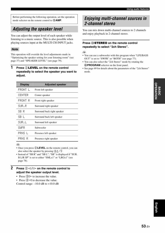
Using audio featuresB
AS
IC
OP
ER
AT
ION
En
glish
You can adjust the output level of each speaker while listening to a music source. This is also possible when playing sources input at the MULTI CH INPUT jacks.
This operation will override the level adjustments made in “Optimizing the speaker setting for your listening room” (see page 37) and “SPEAKER LEVEL” (see page 79).
1 Press 2LEVEL on the remote control repeatedly to select the speaker you want to adjust.
y• Once you press 2LEVEL on the remote control, you can
also select the speaker by pressing 3k / n.• Instead of “SB R” and “SB L”, “SB” is displayed if “SUR.
B L/R SP” is set to either “SMLx1” or “LRGx1” (see page 78).
2 Press 3l / h on the remote control to adjust the speaker output level.• Press 3h to increase the value.• Press 3l to decrease the value.Control range: –10.0 dB to +10.0 dB
You can mix down multi-channel sources to 2 channels and enjoy playback in 2-channel stereo.
Press NSTEREO on the remote control repeatedly to select “2ch Stereo”.
y• You can use a subwoofer with this program when “LFE/BASS
OUT” is set to “SWFR” or “BOTH” (see page 77).• You can also select the “2ch Stereo” mode by rotating the NPROGRAM selector on the front panel.
• See page 69 for details about the parameters of the “2ch Stereo” mode.
Before performing the following operation, set the operation mode selector on the remote control to CAMP.
Adjusting the speaker level
Note
Display Adjusted speaker
FRONT L Front left speaker
CENTER Center speaker
FRONT R Front right speaker
SUR.R Surround right speaker
SB R Surround back right speaker
SB L Surround back left speaker
SUR.L Surround left speaker
SWFR Subwoofer
PRNS L Presence left speaker
PRNS R Presence right speaker
Enjoying multi-channel sources in 2-channel stereo
53 En

There are 2 tuning methods: automatic and manual. Automatic tuning is effective when station signals are strong and there is no interference. If the signal from the station you want to select is weak, tune into it manually. You can also use the automatic and manual preset tuning features to store up to 40 stations (A1 to E8: 8 preset station numbers in each of the 5 preset station groups). Furthermore, you can recall any preset stations and exchange the assignment of two preset stations with each other.
Orient the connected FM and AM antennas for the best reception.
Automatic tuning is effective when station signals are strong and there is no interference.
1 Rotate the CINPUT selector on the front panel to select “TUNER” as the input source.
2 Press IFM/AM to select the reception band.“FM” or “AM” appears in the front panel display.
3 Press KTUNING MODE so that the AUTO indicator lights up in the front panel display.
If a colon (:) appears in the front panel display, tuning is not possible. Press HPRESET/TUNING to turn the colon (:) off.
4 Press GPRESET/TUNING l / h once to begin automatic tuning.When this unit is tuned into a station, the TUNED indicator lights up and the frequency of the received station is shown in the front panel display.• Press Gh to tune into a higher frequency.• Press Gl to tune into a lower frequency.
If the signal received from the station you want to select is weak, tune into it manually.
Manually tuning into an FM station automatically switches the tuner to monaural reception to increase the signal quality.
1 Rotate the CINPUT selector on the front panel to select “TUNER” as the input source.
2 Press IFM/AM to select the reception band.“FM” or “AM” appears in the front panel display.
3 Press KTUNING MODE so that the AUTO indicator disappears from the front panel display.
If a colon (:) appears in the front panel display, tuning is not possible. Press HPRESET/TUNING to turn the colon (:) off.
4 Press GPRESET/TUNING l / h to tune into the desired station manually.Hold down the button to continue searching.
FM/AM tuning
Note
Automatic tuning
AUTO
A F M 9 7 . 7 0 M H z
Lights upNo colon (:)
Manual tuning
Note
A F M 9 7 . 7 0 M H z
No colon (:)
54 En

FM/AM tuningB
AS
IC
OP
ER
AT
ION
En
glish
You can use the automatic preset tuning feature to store up to 40 FM stations with strong signals (A1 to E8: 8 preset station numbers in each of the 5 preset station groups) in order. You can then recall any preset station easily by selecting the preset station number.
1 Rotate the CINPUT selector on the front panel to select “TUNER” as the input source.
2 Press IFM/AM to select “FM” as the reception band.“FM” appears in the front panel display.
3 Press and hold JMEMORY for more than 3 seconds.The preset station number as well as the AUTO and MEMORY indicators flashes. After approximately 5 seconds, automatic presetting starts from the current frequency and proceeds toward higher frequencies.
When automatic preset tuning is completed, the front panel display shows the frequency of the last preset station.
y• You can specify the preset number from which this unit stores
FM stations. Press FA/B/C/D/E and then GPRESET/TUNING l / h repeatedly after you perform step 3 to select the preset station number under which the first station will be stored.
• You can begin tuning toward lower frequencies to store FM stations automatically. Press HPRESET/TUNING so that the colon (:) disappears from the front panel display and then press GPRESET/TUNING l after pressing and holding JMEMORY for more than 3 seconds.
• Any stored station data existing under a preset station number is cleared when you store a new station under the same preset station number.
• If the number of received stations does not reach 40 (E8), automatic preset tuning automatically stops after searching for all the available stations.
• Only FM stations with sufficient signal strength are stored automatically by automatic preset tuning. If the station you want to store is weak in signal strength, tune into it manually and store it as described in “Manual preset tuning”.
• (Europe model only) Only Radio Data System broadcasting station are stored automatically by automatic preset tuning.
You can also store up to 40 stations (A1 to E8: 8 preset station numbers in each of the 5 preset station groups) manually.
1 Tune into a station automatically or manually.See page 54 for tuning instructions.
2 Press JMEMORY on the front panel.The MEMORY indicator flashes in the front panel display for approximately 10 seconds.
3 Press FA/B/C/D/E repeatedly to select a preset station group (A to E) while the MEMORY indicator is flashing.The selected preset station group letter appears. Check that the colon (:) appears in the front panel display.
Automatic preset tuning
AUTO MEMORY
A 1 : F M 9 7 . 7 0 M H z
Flashes Flashes
Notes
Manual preset tuning
MEMORY
Flashes
MEMORY
A : F M 9 7 . 7 0 M H z
Preset station group
FlashesColon (:)
55 En

FM/AM tuning
4 Press GPRESET/TUNING l / h to select a preset station number (1 to 8) while the MEMORY indicator is flashing.• Press Gh to select a higher preset station number.• Press Gl to select a lower preset station number.
5 Press JMEMORY while the MEMORY indicator is flashing.The station band and frequency appear in the front panel display with the preset station group and number you have selected. The MEMORY indicator disappears from the front panel display.
• Any stored station data existing under a preset station number is cleared when you store a new station under the same preset station number.
• The reception mode (stereo or monaural) is stored along with the station frequency.
You can tune into any desired station simply by selecting the preset station group and number under which it was stored.
1 Press FA/B/C/D/E (or 3A/B/C/D/E l / h) repeatedly to select the desired preset station group (A to E).The preset station group letter appears in the front panel display and changes each time you press the button.
2 Press GPRESET/TUNING l / h (or 3PRESET/CH k / n) repeatedly to select the desired preset station number (1 to 8).The preset station group and number appear in the front panel display along with the station band and frequency.
Notes
MEMORY
A 1 : F M 9 7 . 7 0 M H z
Preset station number Flashes
A 1 : F M 9 7 . 7 0 M H z
The displayed station has been stored as A1.
Selecting preset stations
When performing this operation with the remote control, set the operation mode selector to CSOURCE and then press 1TUNER to select “TUNER” as the input source.
A 1 : F M 9 7 . 7 0 M H z
56 En

FM/AM tuningB
AS
IC
OP
ER
AT
ION
En
glish
You can exchange the assignments of two preset stations with each other. The example below describes the procedure to exchange preset station “E1” with “A5”.
1 Select preset station “E1” using FA/B/C/D/E and GPRESET/TUNING l / h on the front panel.See “Selecting preset stations” on page 56.
2 Press and hold HEDIT for more than 3 seconds.“E1” and the MEMORY indicator flash in the front panel display.
3 Select preset station “A5” using FA/B/C/D/E and GPRESET/TUNING l / h.“A5” and the MEMORY indicator flash in the front panel display.
4 Press HEDIT again.“EDIT E1–A5” appears in the front panel display and the assignments of the two preset stations are exchanged.
Exchanging preset stations
MEMORY
E 1 : F M 9 7 . 7 0 M H z
FlashesFlashes
MEMORY
A 5 : F M 9 7 . 7 0 M H z
FlashesFlashes
E D I T E 1 - A 5
57 En

Radio Data System is a data transmission system used by FM stations in many countries. This unit can receive various Radio Data System data such as PS (program service), PTY (program type), RT (radio text), CT (clock time), and EON (enhanced other networks) when receiving Radio Data System broadcasting stations.
Use this feature to display the 4 types of the Radio Data System information: PS (program service), PTY (program type), RT (radio text) and CT (clock time). The corresponding indicators light up in the front panel display.
• You can select one of the Radio Data System display modes only when the corresponding Radio Data System indicator lights up in the front panel display. It may take a while for this unit to receive all of the Radio Data System data from the station.
• You can select only the available Radio Data System display modes being offered by the station.
• If the signals being received are not strong enough, this unit may not be able to utilize the Radio Data System data. In particular, the “RT” mode requires a large amount of data and may not be available even when the other Radio Data System display modes are available.
• In case of poor reception conditions, press KTUNING MODE on the front panel so that the AUTO indicator disappears from the front panel display.
• If the signal strength is weakened by external interference while this unit is receiving the Radio Data System data, the reception may be cut off unexpectedly and “...WAIT” appears in the front panel display.
• When the “RT” mode is selected, this unit can display the program information by a maximum of 64 alphanumeric characters, including the umlaut symbol. Unavailable characters are displayed with the “_” (underscore).
• If the reception is cut off when the “CT” mode is selected, “CT WAIT” appears in the front panel display.
1 Tune into the desired Radio Data System broadcasting station.• We recommend using the automatic preset tuning
to tune into the Radio Data System broadcasting stations (see page 55).
• You can also use PTY SEEK mode to tune into the desired Radio Data System broadcasting station from the preset ones.
2 Press 6FREQ/TEXT on the remote control repeatedly to select the desired Radio Data System display mode.
• Select “PS” to display the name of the Radio Data System program currently being received.
• Select “PTY” to display the type of the Radio Data System program currently being received.
• Select “RT” to display the information on the Radio Data System program currently being received.
• Select “CT” to display the current time.
Radio Data System tuning (Europe model only)
Displaying the Radio Data System information
Notes
CTRTPTYPS
Frequency display
58 En

Radio Data System tuning (Europe model only)B
AS
IC
OP
ER
AT
ION
En
glish
Use this feature to select the desired radio program by program type from the all preset Radio Data System broadcasting stations.
yUse the automatic preset tuning feature to preset Radio Data System broadcasting stations (see page 55).
1 Set the operation mode selector to CSOURCE and then press 1TUNER on the remote control to select “TUNER” as the input source.
2 Press 2BAND repeatedly to select “FM” as the reception band.
3 Press 6PTY SEEK MODE on the remote control to set this unit to the PTY SEEK mode.The name of the program type or “NEWS” flashes in the front panel display.
yTo cancel the PTY SEEK mode, press 6PTY SEEK MODE on the remote control again.
4 Press 3PRESET/CH k / n on the remote control to select the desired program type.The name of the selected program type appears in the front panel display.
Selecting the Radio Data System program type (PTY SEEK mode)
Flashes
NEWS
Program type Descriptions
NEWS News
AFFAIRS Current affairs
INFO General information
SPORT Sports
EDUCATE Education
DRAMA Drama
CULTURE Culture
SCIENCE Science
VARIED Light entertainment
POP M Popular music
ROCK M Rock music
M.O.R. M Middle-of-the-road music (easy-listening)
LIGHT M Light classics
CLASSICS Serious classics
OTHER M Other music
Lights up
POP M
59 En
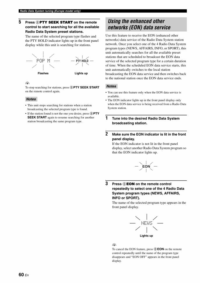
Radio Data System tuning (Europe model only)
5 Press 6PTY SEEK START on the remote control to start searching for all the available Radio Data System preset stations.The name of the selected program type flashes and the PTY HOLD indicator lights up in the front panel display while this unit is searching for stations.
yTo stop searching for stations, press 6PTY SEEK START on the remote control again.
• This unit stops searching for stations when a station broadcasting the selected program type is found.
• If the station found is not the one you desire, press 6PTY SEEK START again to resume searching for another station broadcasting the same program type.
Use this feature to receive the EON (enhanced other networks) data service of the Radio Data System station network. Once you select one of the 4 Radio Data System program types (NEWS, AFFAIRS, INFO, or SPORT), this unit automatically searches for all the available preset stations that are scheduled to broadcast the EON data service of the selected program type for a certain duration of time. When the scheduled EON data service starts, this unit automatically switches to the local station broadcasting the EON data service and then switches back to the national station once the EON data service ends.
• You can use this feature only when the EON data service is available.
• The EON indicator lights up in the front panel display only when the EON data service is being received from a Radio Data System station.
1 Tune into the desired Radio Data System broadcasting station.
2 Make sure the EON indicator is lit in the front panel display.If the EON indicator is not lit in the front panel display, select another Radio Data System program so that the EON indicator lights up.
3 Press 6EON on the remote control repeatedly to select one of the 4 Radio Data System program types (NEWS, AFFAIRS, INFO or SPORT).The name of the selected program type appears in the front panel display.
yTo cancel the EON feature, press 6EON on the remote control repeatedly until the name of the program type disappears and “EON OFF” appears in the front panel display.
Notes
POP M PTY HOLD
Flashes Lights up
Using the enhanced other networks (EON) data service
Notes
EON
NEWS
Lights up
60 En

BA
SIC
O
PE
RA
TIO
NE
ng
lish
Once you have stationed your iPod in a Yamaha iPod universal dock (such as the YDS-10, sold separately) connected to the DOCK terminal of this unit (see page 31), you can enjoy playback of your iPod using the supplied remote control. You can also use the Compressed Music Enhancer mode of this unit to enhance the sound quality of the compression artifacts (such as the MP3 format) stored on your iPod (see page 50).
• Only iPod (Click and Wheel), iPod nano, and iPod mini are supported.• Some features may not be compatible depending on the model or the software version of your iPod.
y• For a complete list of status messages that appear in the front panel display and in the OSD, see the “iPod” section in
“Troubleshooting” on page 122.• Once your iPod is stationed in a Yamaha iPod universal dock (such as the YDS-10, sold separately) connected to the DOCK terminal
of this unit, this unit begins signal transmission with your iPod.• Once the connection between your iPod and this unit is complete, “iPod connected” appears in the front panel display and the DOCK
indicator lights up in the front panel display.• Your iPod battery is automatically charged when your iPod is stationed in a Yamaha iPod universal dock (such as the YDS-10, sold
separately) connected to the DOCK terminal of this unit as long as this unit is turned on. You can also select whether this unit charges the battery of the stationed iPod or not when this unit is in the standby mode by selecting the “STANDBY CHARGE” parameter in “INPUT MENU” (on page 87).
• While the stationed iPod is being charged in the standby mode of this unit, the battery charge indicator (see page 34) appears in the front panel display. Once the charge is complete (or after 4 hours from the start of the charge), the indicator disappears.
You can control your iPod when “V-AUX” is selected as the input source. The operations of your iPod can be done with the aid of the OSD of this unit (menu browse mode) or without it (simple remote mode).
Remote control operation
Controlling iPod in the simple remote mode
You can perform the basic operations of your iPod (play, stop, skip, etc.) using the supplied remote control without the aid of the OSD of this unit.
y• You can view the photos or video clips stored on your iPod.• Operations can be also done with the controls on your iPod.
Controlling iPod in the menu browse mode
You can perform the advanced operations of your iPod using the supplied remote control with the aid of the OSD of this unit. The name of the song being played appears in the front panel display according to the “FL SCROLL” parameter in “OPTION MENU” (see page 89). You can also browse the songs stored on your iPod in the OSD. Further, you can change or adjust settings for your iPod to suit your personal preferences.
• Operations cannot be done with the controls on your iPod.• The Yamaha logo appears in the display window of your iPod.• There are some characters that cannot be displayed in the front
panel display or in the OSD of this unit. Those characters are replaced with underscores “_”.
• You cannot browse the photos or video clips stored on your iPod in the OSD. Use the simple remote mode to enjoy watching the photos or video clips stored on your iPod.
Using iPod™
Notes
Controlling iPod™
Before performing the following operations, set the operation mode selector on the remote control to CSOURCE and then press 1V-AUX.
Button Function
3 ENTER Subsequent menu
k Menu up
n Menu down
l Previous menu
h Subsequent menu
6 ll Search backward (Press and hold)
hh Search forward (Press and hold)
a Skip forward
b Skip backward
s Stop
e Pause (Menu browse mode)Play/Pause (Simple remote mode)
p Play (Menu browse mode)Play/Pause (Simple remote mode)
F MENU Previous menu
I DISPLAY Display
Notes
61 En

Using iPod™
1 Press IDISPLAY on the remote control.The following display appears in the OSD.
2 Press 3k / n / l / h on the remote control to navigate the iPod menu and then press 3ENTER to begin playback of the selected song.
Choices: Playlists (playlists), Artists (artists), Albums (albums), Songs (songs), Genres (genres), Composers (composers), Settings (settings)
• Playlists > Songs• Artists > Albums > Songs• Albums > Songs• Songs• Genres > Artists > Albums > Songs• Composers > Albums > Songs• Settings > Shuffle, Repeat
Shuffle Shuffle
Use this feature to set this unit to play songs or albums in random order.Choices: Off, Songs, Albums• Select “Off ” to deactivate this feature.• Select “Songs” to set this unit to play songs in random
order.• Select “Albums” to set this unit to play albums in
random order.
• When “Shuffle” is set to a setting other than “Off ”, “ ” appears in the top right corner while songs or albums are being shuffled.
• Press 3ENTER repeatedly to toggle between the settings of “Shuffle”.
Repeat Repeat
Use this feature to set this unit to repeat one song or a sequence of songs.Choices: Off, One, All• Select “Off ” to deactivate this feature.• Select “One” to set this unit to repeat one song.• Select “All” to set this unit to repeat a sequence of
songs.
• When “Repeat” is set to a setting other than “Off ”, “ ” or
“ ” appears in the top right corner while one song or a
sequence of songs are being repeated.• Press 3ENTER repeatedly to toggle between the settings of
“Repeat”.
The function of the play information display
1 Track number/total tracks
2 Name of the artist
3 Name of the album
4 Name of the song
5 Progress bar
6 Elapsed time
7 Shuffle and repeat icons
8 (playback), (pausing), (search forward) or (search backward)
9 Remaining time
Before performing the following operations, set the operation mode selector on the remote control to CSOURCE and then press 1V-AUX.
Notes
iPod Top
Playlists >Artists >Albums >Songs >Genres >Composers >Settings >
Notes
1
All
iPod[Play]
1/9FrankieZipperMade-to-orderRoadtoIndia|||||;;;;;;;;;;;;;;;0:51-7:44
All
1
234
56 9
8
7
62 En
BA
SIC
O
PE
RA
TIO
NE
ng
lish
Recording adjustments and other operations are performed from the recording components. Refer to the operating instructions for those components.
• When this unit is set to the standby mode, you cannot record between other components connected to this unit.• TONE CONTROL (see page 52) and the volume settings, the speaker level (see page 79) and the sound field programs (see page 46)
do not affect recorded material.• The source connected to the MULTI CH INPUT jacks of this unit cannot be recorded.• Digital signals input at the DIGITAL INPUT jacks are not output at the analog audio OUT (REC) jacks for recording. Likewise,
analog signals input at the AUDIO IN jacks are not output at the DIGITAL OUTPUT jack. Therefore, if your source component is connected to provide only digital or analog signals, you can only record digital or analog signals.
• A given input source is not output on the same OUT (REC) channel.• S-video and composite video signals pass independently through the video circuits of this unit. Therefore, when recording or dubbing
video signals input from a video source component that provides only an S-video or a composite video signal, you can record only an S-video or a composite video signal on your VCR.
• The analog audio and video signals input at the DOCK terminal can be output at the analog audio OUT (REC) jacks and DVR or VCR OUT jacks for recording.
• Check the copyright laws in your country to record from CDs, radio, etc. Recording of copyrighted material may infringe copyright laws.
yDo a test recording before you start an actual recording.
1 Turn on all the connected components.
2 Rotate the CINPUT selector (or press one of the input selector buttons (1)) to select the source component you want to record from.
3 Start playback on the selected source component or select a broadcast station.
4 Start recording on the recording component.
Recording
CautionThe DTS signal is a digital bitstream. Attempting to digitally record the DTS bitstream will result in noise being recorded. Therefore, if you want to use this unit to record sources encoded in DTS, the following considerations and adjustments need to be made. To play DTS-encoded DVDs and CDs (when using a digital audio connection) on your DTS-compatible player, follow its operating instructions to make a setting so that the analog signal will be output from the player.
Notes
If you play back a video source that uses scrambled or encoded signals to prevent it from being dubbed, the picture itself may be disturbed due to those signals.
63 En
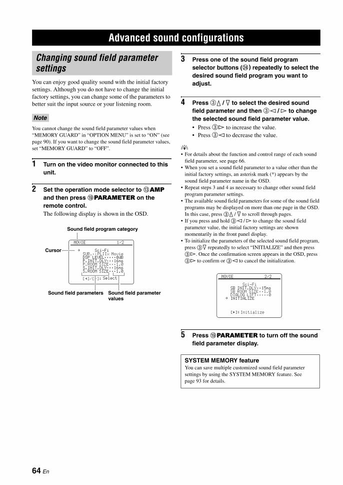
You can enjoy good quality sound with the initial factory settings. Although you do not have to change the initial factory settings, you can change some of the parameters to better suit the input source or your listening room.
You cannot change the sound field parameter values when “MEMORY GUARD” in “OPTION MENU” is set to “ON” (see page 90). If you want to change the sound field parameter values, set “MEMORY GUARD” to “OFF”.
1 Turn on the video monitor connected to this unit.
2 Set the operation mode selector to CAMP and then press IPARAMETER on the remote control.The following display is shown in the OSD.
3 Press one of the sound field program selector buttons (N) repeatedly to select the desired sound field program you want to adjust.
4 Press 3k / n to select the desired sound field parameter and then 3l / h to change the selected sound field parameter value.• Press 3h to increase the value.• Press 3l to decrease the value.
y• For details about the function and control range of each sound
field parameter, see page 66.• When you set a sound field parameter to a value other than the
initial factory settings, an asterisk mark (*) appears by the sound field parameter name in the OSD.
• Repeat steps 3 and 4 as necessary to change other sound field program parameter settings.
• The available sound field parameters for some of the sound field programs may be displayed on more than one page in the OSD. In this case, press 3k / n to scroll through pages.
• If you press and hold 3l / h to change the sound field parameter value, the initial factory settings are shown momentarily in the front panel display.
• To initialize the parameters of the selected sound field program, press 3n repeatedly to select “INITIALIZE” and then press 3h. Once the confirmation screen appears in the OSD, press 3h to confirm or 3l to cancel the initialization.
5 Press IPARAMETER to turn off the sound field parameter display.
Advanced sound configurations
Changing sound field parameter settings
Note
Sound field program category
Sound field parameters Sound field parameter values
[p]/[[]:
MOVIE 1/2
Sci-FiSUR.;;PLIIx MovieDSP LEVEL;;;;;0dBP.INIT.DLY;;;16msP.ROOM SIZE;;;1.0S.INIT.DLY;;;16msS.ROOM SIZE;;;1.0
Select
.Cursor
SYSTEM MEMORY featureYou can save multiple customized sound field parameter settings by using the SYSTEM MEMORY feature. See page 93 for details.
[[]:
MOVIE 2/2
Sci-FiSB INIT.DLY;;15msSB ROOM SIZE;;1.0DIALOG LIFT;;;;;0INITIALIZE
Initialize
.
64 En

Advanced sound configurationsA
DVA
NC
ED
O
PE
RA
TIO
NE
ng
lish
Basic configuration of sound field programs
Each sound field program has some parameters defining the characteristics of the program. To customize the selected sound field program, adjust “DSP LEVEL” and/or “DIALOG LIFT” first, and then try other parameters.
yTo change sound field parameter settings, see page 64 for details.
Adjusting the effect sound level of the sound field programs (DSP LEVEL)Sound field programs add effect sounds (DSP effect sounds) to the original source sound to create sound field in the listening room. Use the “DSP LEVEL” parameter to adjust the level of the effect sounds.
Adjust “DSP LEVEL” as follows:
Increase the value of “DSP LEVEL” when• the effect sound of the selected sound field
program is too weak.• you cannot recognize any difference between the
sound field programs.
Decrease the value of “DSP LEVEL” when• the sound is vague.• you feel that the additional sound effect is
excessive.
Control range: –6 dB to +3 dB
Adjusting the vertical dialogue position (DIALOG LIFT)Use this feature to adjust the vertical position of the dialogues in movies. The ideal position of the dialogues is at the center of the video monitor screen.
If the dialogues are heard at the lower position of the video monitor screen, increase the value of “DIALOG LIFT”.
Choices: 0, 1, 2, 3, 4, 5“0” (initial setting) is the lowest position, and “5” is the highest position.
• “DIALOG LIFT” is available only when “PRESENCE SP” is set to “ON” (see page 78).
• You cannot move the dialogue position down from the initial dialogue position.
The DSP effect sound level is low.
The DSP effect sound level is high.
Notes
The ideal dialogue position
Move up to the ideal dialogue position.
65 En

Advanced sound configurations
Sound field parameter descriptionsYou can adjust the values of certain digital sound field parameters so that the sound fields are recreated accurately in your listening room. Not all of the following parameters are found in every program.
yTo change sound field parameter settings to suit your listening environment, see page 64 for details.
Sound field parameter Features
INIT.DLYP.INIT.DLYS.INIT.DLYSB INIT.DLY
Initial delay. Presence, surround, and surround back sound field initial delay. Changes the apparent size of the sound field by adjusting the delay between the direct sound and the first reflection heard by the listener. The smaller the value, the smaller the sound field seems to the listener.
yWhen you adjust the initial delay parameters, we also recommend that you adjust the corresponding room size parameters likewise. This adjustment is especially effective for the CINEMA DSP programs.
Control range: 1 to 99 ms (INIT.DLY and P.INIT.DLY)1 to 49 ms (S.INIT.DLY and SB INIT.DLY)
Source sound
Early reflections
Time Time TimeDelay Delay Delay
Sound source
Reflection face
Lev
el
Small value = 1 ms Large value = 99 ms
Lev
el
Lev
el
66 En
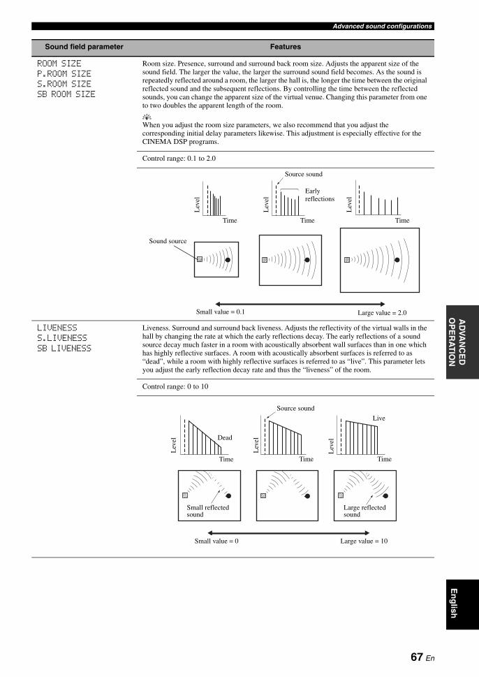
Advanced sound configurationsA
DVA
NC
ED
O
PE
RA
TIO
NE
ng
lish
ROOM SIZEP.ROOM SIZES.ROOM SIZESB ROOM SIZE
Room size. Presence, surround and surround back room size. Adjusts the apparent size of the sound field. The larger the value, the larger the surround sound field becomes. As the sound is repeatedly reflected around a room, the larger the hall is, the longer the time between the original reflected sound and the subsequent reflections. By controlling the time between the reflected sounds, you can change the apparent size of the virtual venue. Changing this parameter from one to two doubles the apparent length of the room.
yWhen you adjust the room size parameters, we also recommend that you adjust the corresponding initial delay parameters likewise. This adjustment is especially effective for the CINEMA DSP programs.
Control range: 0.1 to 2.0
LIVENESSS.LIVENESSSB LIVENESS
Liveness. Surround and surround back liveness. Adjusts the reflectivity of the virtual walls in the hall by changing the rate at which the early reflections decay. The early reflections of a sound source decay much faster in a room with acoustically absorbent wall surfaces than in one which has highly reflective surfaces. A room with acoustically absorbent surfaces is referred to as “dead”, while a room with highly reflective surfaces is referred to as “live”. This parameter lets you adjust the early reflection decay rate and thus the “liveness” of the room.
Control range: 0 to 10
Sound field parameter Features
Lev
el
Lev
el
Lev
el
Time Time Time
Source sound
Early reflections
Small value = 0.1 Large value = 2.0
Sound source
Source sound
Lev
el
Lev
el
Lev
elDead
Live
Time Time Time
Small reflected sound
Large reflected sound
Small value = 0 Large value = 10
67 En

Advanced sound configurations
REV.TIME Reverberation time. Adjusts the amount of time taken for the dense, subsequent reverberation sound to decay by 60 dB at 1 kHz. This changes the apparent size of the acoustic environment over an extremely wide range. Set a longer reverberation time to get more sustaining reverberation sound, and set a shorter time to get articulate sound.
Control range: 1.0 to 5.0 s
REV.DELAY Reverberation delay. Adjusts the time difference between the beginning of the direct sound and the beginning of the reverberation sound. The larger the value, the later the reverberation sound begins. A later reverberation sound makes you feel as if you are in a larger acoustic environment.
Control range: 0 to 250 ms
REV.LEVEL Reverberation level. Adjusts the volume of the reverberation sound. The larger the value, the stronger the reverberation becomes.
Control range: 0 to 100%
Sound field parameter Features
Reverberation ReverberationSource sound
REV.TIME REV.TIME REV.TIMESound source Short
reverberationLong reverberation
Small value = 1.0 s Large value = 5.0 s
Early reflections
60 dB 60 dB 60 dB
(dB)
Lev
el Source sound
Reverberation
REV.TIMEREV.DELAY
Time
60 dB
Source sound
Lev
el
REV. LEVEL
Time
68 En

Advanced sound configurationsA
DVA
NC
ED
O
PE
RA
TIO
NE
ng
lish
Selecting decoders for 2-channel sources (surround decode mode)
Use this feature to play back sources with selected decoders. You can play back 2-channel sources on multi-channels.
Set the operation mode selector to CAMP and then press KSUR. DECODE repeatedly on the remote control to select the surround decode mode.
You can select the desired surround decoder mode depending on the type of source you are playing and your personal preference.
yYou can change the decoder parameter settings. Press IPARAMETER and then 3k / n repeatedly on the remote control to select the desired decoder parameter. You can change the value of the selected parameter by pressing 3l / h repeatedly on the remote control.
Sound field parameter Features
DIRECT(“2ch Stereo” only)
2-channel stereo direct. Bypasses the decoders and DSP processors of this unit for pure hi-fi stereo sound when playing 2-channel analog sources.
Choices: AUTO, OFF
y• Select “AUTO” to bypass the decoders, DSP processors and the tone control circuitry only when
“BASS” and “TREBLE” are set to 0 dB (see page 52).• Select “OFF” not to bypass the decoders, DSP processors and the tone control circuitry when
“BASS” and “TREBLE” are set to 0 dB.• When multi-channel signals are input, they are downmixed to 2 channels and output from the front
left and right speakers.• The low-frequency signals of the front left and right channels are redirected to the subwoofer in the
following cases:– “LFE/BASS OUT” is set to “BOTH” (see page 77).– “FRONT SP” is set to “SMALL” (see page 77) and “LFE/BASS OUT” is set to “SWFR” (see
page 77).
CT LEVELSL LEVELSR LEVELSB LEVELPL LEVELPR LEVEL(“7ch Stereo” only)
7-channel stereo center, surround left, surround right, surround back, presence left and presence right levels. Adjusts the volume level of each channel in the 7-channel stereo mode.
Control range: 0 to 100%
EFFECT LEVEL(“Straight Enhancer” and “7ch Enhancer” only)
Straight and 7-channel Compressed Music Enhancer effect level. The high-frequency signals of some sources may be emphasized too much. In this case, set the effect level to “LOW”.
Choices: HIGH, LOW
• Select “HIGH” for a high effect level.• Select “LOW” for a low effect level.
Selecting decoders
69 En
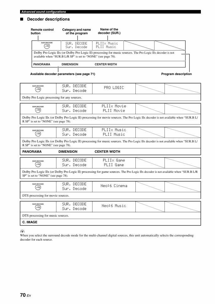
Advanced sound configurations
Decoder descriptions
yWhen you select the surround decode mode for the multi-channel digital sources, this unit automatically selects the corresponding decoder for each source.
SUR. DECODESur. Decode
PRO LOGIC
Dolby Pro Logic processing for any sources.
SUR. DECODESur. Decode
PLIIx MoviePLII Movie
Dolby Pro Logic IIx (or Dolby Pro Logic II) processing for movie sources. The Pro Logic IIx decoder is not available when “SUR.B L/R SP” is set to “NONE” (see page 78).
SUR. DECODESur. Decode
PLIIx MusicPLII Music
Dolby Pro Logic IIx (or Dolby Pro Logic II) processing for music sources. The Pro Logic IIx decoder is not available when “SUR.B L/R SP” is set to “NONE” (see page 78).
PANORAMA DIMENSION CENTER WIDTH
SUR. DECODESur. Decode
PLIIx GamePLII Game
Dolby Pro Logic IIx (or Dolby Pro Logic II) processing for game sources. The Pro Logic IIx decoder is not available when “SUR.B L/R SP” is set to “NONE” (see page 78).
CENTER WIDTHDIMENSION
PLIIMusic
PLIIxMusicSUR. DECODE
Sur. Decode
PANORAMA
+10
SUR.DECODE
Dolby Pro Logic IIx (or Dolby Pro Logic II) processing for music sources. The Pro Logic IIx decoder is not available when “SUR.B L/R SP” is set to “NONE” (see page 78).
Available decoder parameters (see page 71) Program description
Remote control button
Name of the decoder (SUR.)
Category and name of the program
+10
SUR.DECODE
+10
SUR.DECODE
+10
SUR.DECODE
+10
SUR.DECODE
SUR. DECODESur. Decode
Neo:6 Cinema
DTS processing for movie sources.
+10
SUR.DECODE
SUR. DECODESur. Decode
Neo:6 Music
DTS processing for music sources.
C. IMAGE
+10
SUR.DECODE
70 En

Advanced sound configurationsA
DVA
NC
ED
O
PE
RA
TIO
NE
ng
lish
Decoder parameter descriptions
Selecting decoders used with sound field programs (SUR.)
Use this feature to select the desired decoder used with MOVIE sound field programs (except “Mono Movie”). See page 49 for details about MOVIE sound field program.
Available decoders
Decoder parameter Features
PANORAMA(“PLIIx Music” and “PLII Music” only)
Pro Logic IIx Music and Pro Logic II Music panorama. Sends stereo signals to the surround speakers as well as the front speakers for a wraparound effect.
Choices: OFF, ON
DIMENSION(“PLIIx Music” and “PLII Music” only)
Pro Logic IIx Music and Pro Logic II Music dimension. Adjusts the sound field either towards the front or towards the rear.
Control range: –3 (towards the rear) to +3 (towards the front)
Initial setting: STD (standard)
CENTER WIDTH(“PLIIx Music” and “PLII Music” only)
Pro Logic IIx Music and Pro Logic II Music center width. Moves the center channel output completely towards the center speaker or towards the front left and right speakers. A larger value moves the center channel output towards the front left and right speakers.
Control range: 0 (center channel sound is output only from the center speaker) to 7 (center channel sound is output only from the front left and right speakers)
Initial setting: 3
C.IMAGE(“Neo:6 Music” only)
DTS Neo:6 Music center image. Adjusts the front left and right channel output relative to the center channel to make the center channel more or less dominant as necessary.
Control range: 0.0 (center channel sound is output only from the front left and right speakers) to1.0 (center channel sound output only from the center speaker)
Initial setting: 0.3
Decoder Functions
PLIIx MoviePLII Movie
Dolby Pro Logic IIx (or Dolby Pro Logic II) processing for movie sources. The Pro Logic IIx decoder is not available when “SUR.B L/R SP” is set to “NONE” (see page 78).
Neo:6 Cinema DTS processing for movie sources
71 En

You can use the following parameters in “SET MENU” to adjust a variety of system settings and customize the way this unit operates. Change the initial settings (indicated in bold under each parameter) to reflect the needs of your listening environment.
Auto setup AUTO SETUP
Use this feature to automatically adjust speaker and system parameters (see page 37).
Manual setup MANUAL SETUP
Use this feature to manually adjust speaker and system parameters.
Basic menu 1 BASIC MENU
Customizing this unit (MANUAL SETUP)
Menu Parameter Functions Page
A)SPEAKER SET LFE/BASS OUT Selects the speakers that output the LFE (low-frequency effect) and the low-frequency signals.
77
FRONT SP Selects the size of the front speakers. 77
CENTER SP Selects the size of the center speaker. 77
SUR. L/R SP Selects the size and number of the surround speakers. 78
SUR.B L/R SP Selects the size and number of the surround back speakers. 78
PRESENCE SP Selects whether this unit uses the presence speakers. 78
CROSS OVER Selects the crossover frequency of all the speakers set to “SML” (or “SMALL”) or to “NONE” in “SPEAKER SET” (see pages 77 and 78).
78
SUBWOOFER PHASE Switches the phase of your subwoofer if bass sounds are lacking or unclear.
79
PRIORITY Prioritizes either the presence or the surround back speakers when playing back sources that contain surround back channel signals using the CINEMA DSP sound field programs.
79
B)SPEAKER LEVEL FR.L/FR.R/CENT./SUR.L/SUR.R/SB L/SB R/SWFR/PR.L/PR.R
Adjust the balance the speaker levels between the front left or surround left speakers and each speaker selected in “SPEAKER SET” (see page 77).
79
C)SP DISTANCE UNIT Selects the unit to adjust the speaker distance. 80
FRONT L/FRONT R/CENTER/SUR. L/SUR. R/SB L/SB R/SWFR/PRNS L/PRNS R
Adjust the distance of each speaker and the delay applied to the respective channel.
80
D)TEST TONE — Turns the test tone output on or off for the “SPEAKER SET”, “SPEAKER LEVEL”, and “SP DISTANCE” settings.
80
72 En
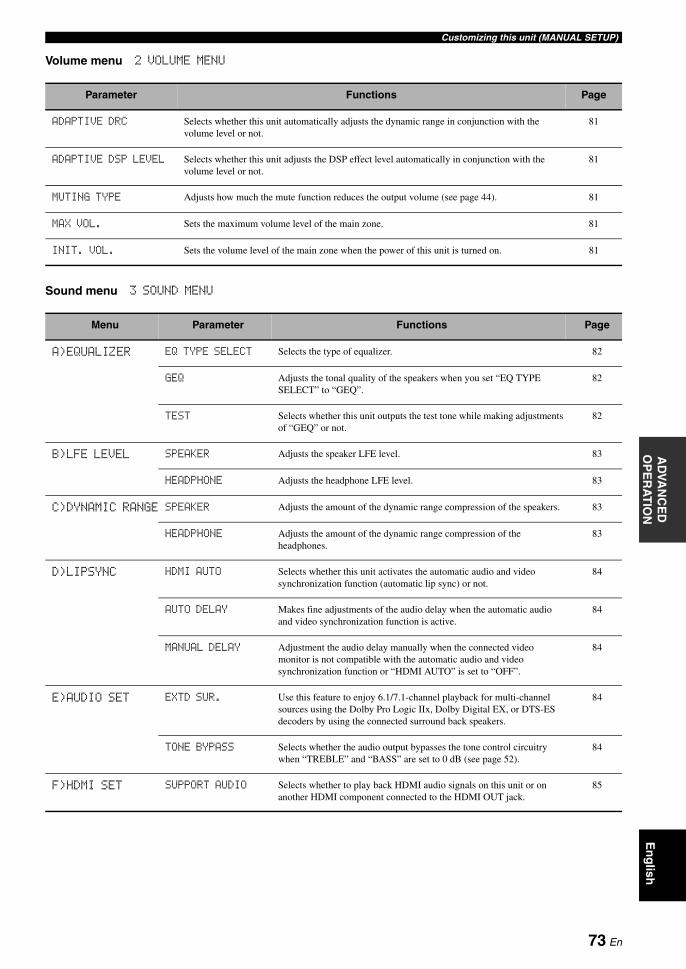
Customizing this unit (MANUAL SETUP)A
DVA
NC
ED
O
PE
RA
TIO
NE
ng
lish
Volume menu 2 VOLUME MENU
Sound menu 3 SOUND MENU
Parameter Functions Page
ADAPTIVE DRC Selects whether this unit automatically adjusts the dynamic range in conjunction with the volume level or not.
81
ADAPTIVE DSP LEVEL Selects whether this unit adjusts the DSP effect level automatically in conjunction with the volume level or not.
81
MUTING TYPE Adjusts how much the mute function reduces the output volume (see page 44). 81
MAX VOL. Sets the maximum volume level of the main zone. 81
INIT. VOL. Sets the volume level of the main zone when the power of this unit is turned on. 81
Menu Parameter Functions Page
A)EQUALIZER EQ TYPE SELECT Selects the type of equalizer. 82
GEQ Adjusts the tonal quality of the speakers when you set “EQ TYPE SELECT” to “GEQ”.
82
TEST Selects whether this unit outputs the test tone while making adjustments of “GEQ” or not.
82
B)LFE LEVEL SPEAKER Adjusts the speaker LFE level. 83
HEADPHONE Adjusts the headphone LFE level. 83
C)DYNAMIC RANGE SPEAKER Adjusts the amount of the dynamic range compression of the speakers. 83
HEADPHONE Adjusts the amount of the dynamic range compression of the headphones.
83
D)LIPSYNC HDMI AUTO Selects whether this unit activates the automatic audio and video synchronization function (automatic lip sync) or not.
84
AUTO DELAY Makes fine adjustments of the audio delay when the automatic audio and video synchronization function is active.
84
MANUAL DELAY Adjustment the audio delay manually when the connected video monitor is not compatible with the automatic audio and video synchronization function or “HDMI AUTO” is set to “OFF”.
84
E)AUDIO SET EXTD SUR. Use this feature to enjoy 6.1/7.1-channel playback for multi-channel sources using the Dolby Pro Logic IIx, Dolby Digital EX, or DTS-ES decoders by using the connected surround back speakers.
84
TONE BYPASS Selects whether the audio output bypasses the tone control circuitry when “TREBLE” and “BASS” are set to 0 dB (see page 52).
84
F)HDMI SET SUPPORT AUDIO Selects whether to play back HDMI audio signals on this unit or on another HDMI component connected to the HDMI OUT jack.
85
73 En
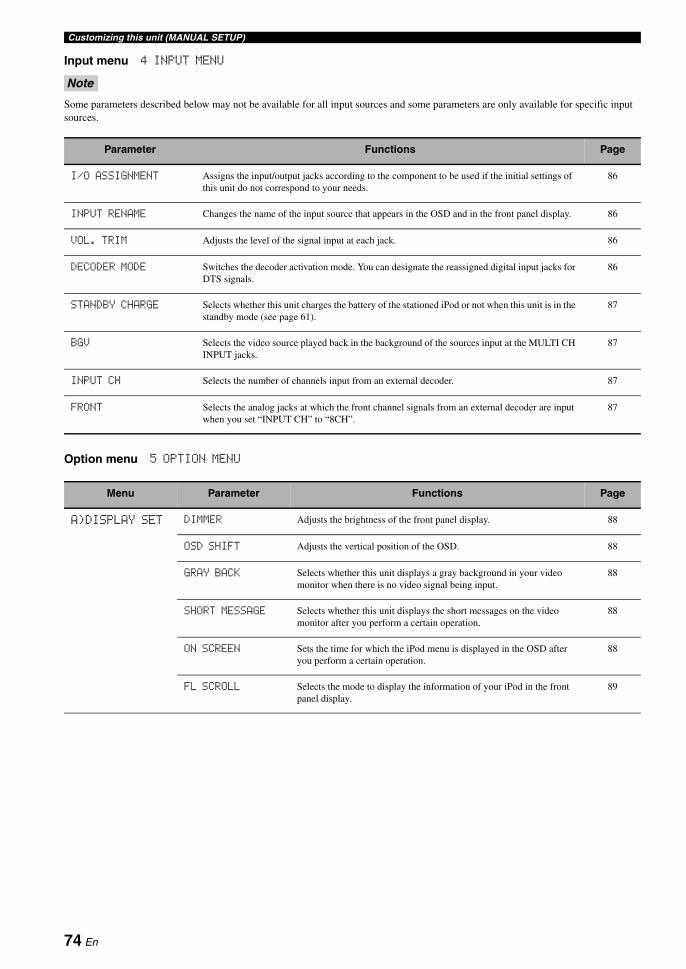
Customizing this unit (MANUAL SETUP)
Input menu 4 INPUT MENU
Some parameters described below may not be available for all input sources and some parameters are only available for specific input sources.
Option menu 5 OPTION MENU
Note
Parameter Functions Page
I/O ASSIGNMENT Assigns the input/output jacks according to the component to be used if the initial settings of this unit do not correspond to your needs.
86
INPUT RENAME Changes the name of the input source that appears in the OSD and in the front panel display. 86
VOL. TRIM Adjusts the level of the signal input at each jack. 86
DECODER MODE Switches the decoder activation mode. You can designate the reassigned digital input jacks for DTS signals.
86
STANDBY CHARGE Selects whether this unit charges the battery of the stationed iPod or not when this unit is in the standby mode (see page 61).
87
BGV Selects the video source played back in the background of the sources input at the MULTI CH INPUT jacks.
87
INPUT CH Selects the number of channels input from an external decoder. 87
FRONT Selects the analog jacks at which the front channel signals from an external decoder are input when you set “INPUT CH” to “8CH”.
87
Menu Parameter Functions Page
A)DISPLAY SET DIMMER Adjusts the brightness of the front panel display. 88
OSD SHIFT Adjusts the vertical position of the OSD. 88
GRAY BACK Selects whether this unit displays a gray background in your video monitor when there is no video signal being input.
88
SHORT MESSAGE Selects whether this unit displays the short messages on the video monitor after you perform a certain operation.
88
ON SCREEN Sets the time for which the iPod menu is displayed in the OSD after you perform a certain operation.
88
FL SCROLL Selects the mode to display the information of your iPod in the front panel display.
89
74 En

Customizing this unit (MANUAL SETUP)A
DVA
NC
ED
O
PE
RA
TIO
NE
ng
lish
System memory SYSTEM MEMORY
Use this feature to create your favorite settings and assign the settings to each MSYSTEM MEMORY button (see page 93).
Signal information SIGNAL INFO
Use this feature to check audio signal information (see page 44).
B)VIDEO SET VIDEO CONV. Selects whether to convert the video signals input at the VIDEO, S VIDEO, and COMPONENT VIDEO jacks.
89
COMPONENT I/P Selects whether this unit activates the analog interlace/progressive conversion of the analog video signals input at the VIDEO, S VIDEO, and COMPONENT VIDEO jacks so that the analog video signals deinterlaced from 480i (NTSC)/576i (PAL) to 480p/576p are output at the COMPONENT MONITOR OUT jacks.
89
HDMI SCALING Selects whether this unit activates the HDMI up-conversion of the analog video signals input at the VIDEO, S VIDEO, and COMPONENT VIDEO jacks so that the up-scaled analog video signals are output at the HDMI OUT jack.
89
HDMI ASPECT Adjusts the aspect ratio for analog video signals output at the HDMI OUT jack.
90
C)MEMORY GUARD — Prevents accidental changes to sound field program parameter values and other system settings.
90
D)INIT. CONFIG AUDIO SELECT Designates the default audio input jack select setting for the input sources connected to the DIGITAL INPUT jacks when you turn on the power of this unit.
91
DECODER MODE Designates the default decoder mode for the input sources connected to the DIGITAL INPUT jacks when you turn on the power of this unit.
91
EXTD SUR. Designates the extended decoder mode for the input sources connected to the DIGITAL INPUT jacks when you turn on the power of this unit.
91
E)ZONE SET AMP Selects how the Zone 2 or Zone 3 speakers are amplified. 91
VOLUME Selects whether this unit controls the volume level of the audio signals output at the ZONE OUT (ZONE 2 or ZONE 3) jacks.
92
MAX VOL. Adjusts the maximum volume level in Zone 2 or Zone 3. 92
INIT. VOL. Sets the volume level of Zone 2 or Zone 3 when you turn on the power of this unit.
92
Menu Parameter Functions Page
75 En

Customizing this unit (MANUAL SETUP)
Use the remote control to access and adjust each parameter.
y• You can change the “SET MENU” parameters while this unit is
reproducing sound.• If you press IPARAMETER during the “SET MENU”
operation, the “SET MENU” operation is canceled.• Repeat the following procedure to select and adjust each
parameter setting.• Press 4RETURN to return to the previous menu level.
1 Set the operation mode selector to CAMP and then press FSET MENU to enter “SET MENU”.The top “SET MENU” display appears in the OSD.
2 Press 3k / n to select “MANUAL SETUP”.
3 Press 3ENTER to enter “MANUAL SETUP”.The “MANUAL SETUP” display appears in the OSD.
4 Press 3k / n repeatedly and then press 3ENTER to select and enter the desired menu.The following displays are examples where “SOUND MENU” is selected.
5 Press 3k / n repeatedly and then press 3ENTER to select and enter the desired submenu.The following display is an example where “LFE LEVEL” is selected.
6 Press 3k / n to select the desired parameter and then 3l / h to change the parameter settings.• Press 3h to increase the value.• Press 3l to decrease the value.
7 Press FSET MENU to exit from “SET MENU”.
Using SET MENU
[]/[]:[ENTER]:
[ p
SET MENU
;AUTO SETUP;MANUAL SETUP;SYSTEM MEMORY;SIGNAL INFO
UP/DOWNEnter
.
[]/[]:[ENTER]:
[ p
MANUAL SETUP
1 BASIC MENU2 VOLUME MENU3 SOUND MENU4 INPUT MENU5 OPTION MENU
UP/DOWNEnter
.
[]/[]:[ENTER]:
[ p
3 SOUND MENU
A)EQUALIZERB)LFE LEVELC)DYNAMIC RANGED)LIPSYNCE)AUDIO SETF)HDMI SET
UP/DOWNEnter
.
[]/[]:[p]/[[]:
[ p
B)LFE LEVEL
SPEAKER;;;;;;0dBHEADPHONE;;-20dB
UP/DOWNAdjust
.
76 En
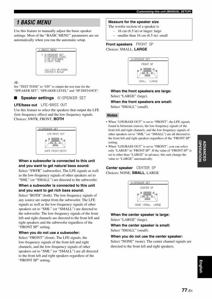
Customizing this unit (MANUAL SETUP)A
DVA
NC
ED
O
PE
RA
TIO
NE
ng
lish
Use this feature to manually adjust the basic speaker settings. Most of the “BASIC MENU” parameters are set automatically when you run the automatic setup.
ySet “TEST TONE” to “ON” to output the test tone for the “SPEAKER SET”, “SPEAKER LEVEL” and “SP DISTANCE”.
Speaker settings A)SPEAKER SET
LFE/bass out LFE/BASS OUT
Use this feature to select the speakers that output the LFE (low-frequency effect) and the low-frequency signals.Choices: SWFR, FRONT, BOTH
When a subwoofer is connected to this unit and you want to get natural bass sound:Select “SWFR” (subwoofer). The LFE signals as well as the low-frequency signals of other speakers set to “SML” (or “SMALL”) are directed to the subwoofer.
When a subwoofer is connected to this unit and you want to get rich bass sound:Select “BOTH” (both). The low-frequency signals of any source are output from the subwoofer. The LFE signals as well as the low-frequency signals of other speakers set to “SML” (or “SMALL”) are directed to the subwoofer. The low-frequency signals of the front left and right channels are directed to the front left and right speakers and the subwoofer regardless of the “FRONT SP” setting.
When you do not use a subwoofer:Select “FRONT” (front). The LFE signals, the low-frequency signals of the front left and right channels, and the low-frequency signals of other speakers set to “SML” (or “SMALL”) are all directed to the front left and right speakers regardless of the “FRONT SP” setting.
Front speakers FRONT SP
Choices: SMALL, LARGE
When the front speakers are large:Select “LARGE” (large).
When the front speakers are small:Select “SMALL” (small).
• When “LFE/BASS OUT” is set to “FRONT”, the LFE signals found in bitstream sources, the low-frequency signals of the front left and right channels, and the low-frequency signals of other speakers set to “SML” (or “SMALL”) are all directed to the front left and right speakers regardless of the “FRONT SP” setting.
• When “LFE/BASS OUT” is set to “FRONT”, you can select only “LARGE” in “FRONT SP”. If the value of “FRONT SP” is set to other than “LARGE” in advance, this unit change the value to “LARGE” automatically.
Center speaker CENTER SP
Choices: NONE, SMALL, LARGE
When the center speaker is large:Select “LARGE” (large).
When the center speaker is small:Select “SMALL” (small).
When you do not use the center speaker:Select “NONE” (none). The center channel signals are directed to the front left and right speakers.
1 BASIC MENU
[]/[]:[ENTER]:
[ p1 BASIC MENU
A)SPEAKER SETB)SPEAKER LEVELC)SP DISTANCED)TEST TONE
UP/DOWNEnter
.
A)SPEAKER SET
LFE/BASS OUT
SWFR FRONT>BOTH
Measure for the speaker sizeThe woofer section of a speaker is
– 16 cm (6.5 in) or larger: large– smaller than 16 cm (6.5 in): small
Notes
A)SPEAKER SET
FRONT SP
SMALL >LARGE
A)SPEAKER SET
CENTER SP
NONE >SMALL LARGE
77 En
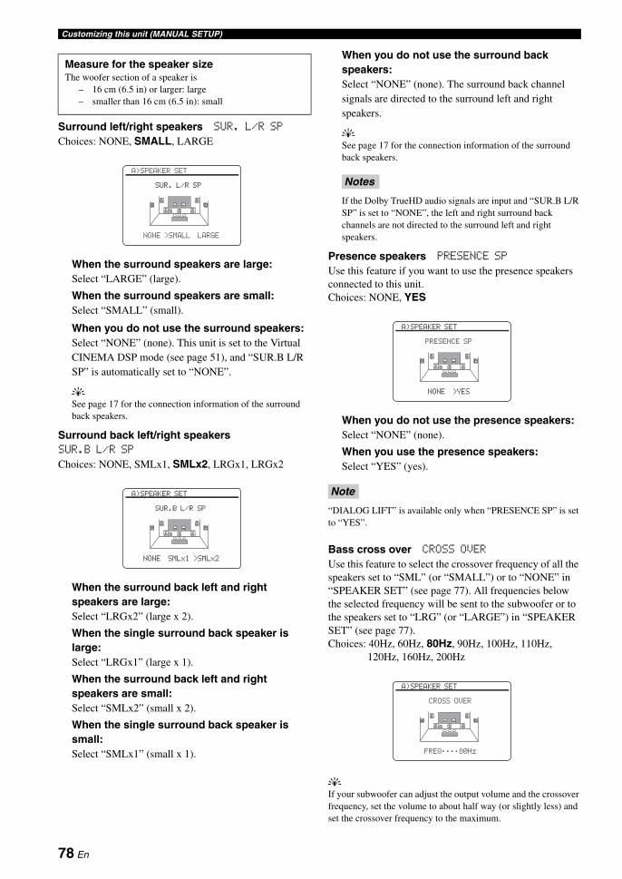
Customizing this unit (MANUAL SETUP)
Surround left/right speakers SUR. L/R SP
Choices: NONE, SMALL, LARGE
When the surround speakers are large:Select “LARGE” (large).
When the surround speakers are small:Select “SMALL” (small).
When you do not use the surround speakers:Select “NONE” (none). This unit is set to the Virtual CINEMA DSP mode (see page 51), and “SUR.B L/R SP” is automatically set to “NONE”.
ySee page 17 for the connection information of the surround back speakers.
Surround back left/right speakersSUR.B L/R SP
Choices: NONE, SMLx1, SMLx2, LRGx1, LRGx2
When the surround back left and right speakers are large:Select “LRGx2” (large x 2).
When the single surround back speaker is large:Select “LRGx1” (large x 1).
When the surround back left and right speakers are small:Select “SMLx2” (small x 2).
When the single surround back speaker is small:Select “SMLx1” (small x 1).
When you do not use the surround back speakers:Select “NONE” (none). The surround back channel signals are directed to the surround left and right speakers.
ySee page 17 for the connection information of the surround back speakers.
If the Dolby TrueHD audio signals are input and “SUR.B L/R SP” is set to “NONE”, the left and right surround back channels are not directed to the surround left and right speakers.
Presence speakers PRESENCE SP
Use this feature if you want to use the presence speakers connected to this unit.Choices: NONE, YES
When you do not use the presence speakers:Select “NONE” (none).
When you use the presence speakers:Select “YES” (yes).
“DIALOG LIFT” is available only when “PRESENCE SP” is set to “YES”.
Bass cross over CROSS OVER
Use this feature to select the crossover frequency of all the speakers set to “SML” (or “SMALL”) or to “NONE” in “SPEAKER SET” (see page 77). All frequencies below the selected frequency will be sent to the subwoofer or to the speakers set to “LRG” (or “LARGE”) in “SPEAKER SET” (see page 77).Choices: 40Hz, 60Hz, 80Hz, 90Hz, 100Hz, 110Hz,
120Hz, 160Hz, 200Hz
yIf your subwoofer can adjust the output volume and the crossover frequency, set the volume to about half way (or slightly less) and set the crossover frequency to the maximum.
Measure for the speaker sizeThe woofer section of a speaker is
– 16 cm (6.5 in) or larger: large– smaller than 16 cm (6.5 in): small
A)SPEAKER SET
SUR. L/R SP
NONE >SMALL LARGE
A)SPEAKER SET
SUR.B L/R SP
NONE SMLx1 >SMLx2
Notes
Note
A)SPEAKER SET
PRESENCE SP
NONE >YES
A)SPEAKER SET
CROSS OVER
FREQ;;;;80Hz
78 En
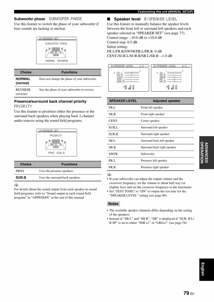
Customizing this unit (MANUAL SETUP)A
DVA
NC
ED
O
PE
RA
TIO
NE
ng
lish
Subwoofer phase SUBWOOFER PHASE
Use this feature to switch the phase of your subwoofer if bass sounds are lacking or unclear.
Presence/surround back channel priority PRIORITY
Use this feature to prioritize either the presence or the surround back speakers when playing back 2-channel audio sources using the sound field programs.
yFor details about the sound output from each speaker in sound field programs, refer to “Sound output in each sound field program” in “APPENDIX” at the end of this manual.
Speaker level B)SPEAKER LEVEL
Use this feature to manually balance the speaker levels between the front left or surround left speakers and each speaker selected in “SPEAKER SET” (see page 77).Control range: –10.0 dB to +10.0 dBControl step: 0.5 dBInitial setting:FR.L/FR.R/SWFR/PR.L/PR.R: 0 dBCENT./SUR.L/SUR.R/SB L/SB R: –1.0 dB
y• If your subwoofer can adjust the output volume and the
crossover frequency, set the volume to about half way (or slightly less) and set the crossover frequency to the maximum.
• Set “TEST TONE” to “ON” to output the test tone for the “SPEAKER LEVEL” setting (see page 80).
• The available speaker channels differ depending on the setting of the speakers.
• Instead of “SB L” and “SB R”, “SB” is displayed if “SUR. B L/R SP” is set to either “SMLx1” or “LRGx1” (see page 78).
Choice Functions
NORMAL(normal)
Does not change the phase of your subwoofer.
REVERSE(reverse)
Sets the phase of your subwoofer to reverse.
Choice Functions
PRNS Uses the presence speakers.
SUR.B Uses the surround back speakers.
A)SPEAKER SET
SUBWOOFER PHASE
>NORMAL REVERSE
A)SPEAKER SET
PRIORITY
PRNS >SUR.B
SPEAKER LEVEL Adjusted speaker
FR.L Front left speaker
FR.R Front right speaker
CENT. Center speaker
SUR.L Surround left speaker
SUR.R Surround right speaker
SB L Surround back left speaker
SB R Surround back right speaker
SWFR Subwoofer
PR.L Presence left speaker
PR.R Presence right speaker
Notes
B)SPEAKER LEVEL 1/2
FR.LFR.RCENT.SUR.LSUR.R
.
B)SPEAKER LEVEL 2/2
SB LSB RSWFRPR.LPR.R
.
79 En
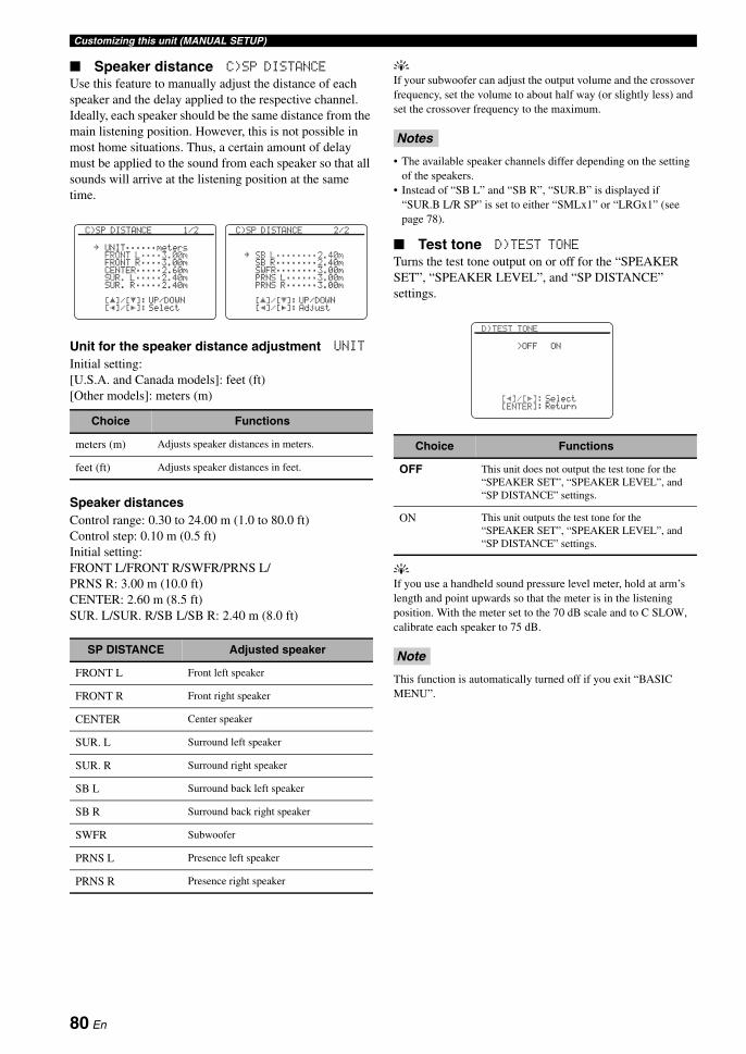
Customizing this unit (MANUAL SETUP)
Speaker distance C)SP DISTANCE
Use this feature to manually adjust the distance of each speaker and the delay applied to the respective channel. Ideally, each speaker should be the same distance from the main listening position. However, this is not possible in most home situations. Thus, a certain amount of delay must be applied to the sound from each speaker so that all sounds will arrive at the listening position at the same time.
Unit for the speaker distance adjustment UNIT
Initial setting:[U.S.A. and Canada models]: feet (ft) [Other models]: meters (m)
Speaker distancesControl range: 0.30 to 24.00 m (1.0 to 80.0 ft)Control step: 0.10 m (0.5 ft)Initial setting:FRONT L/FRONT R/SWFR/PRNS L/PRNS R: 3.00 m (10.0 ft)CENTER: 2.60 m (8.5 ft)SUR. L/SUR. R/SB L/SB R: 2.40 m (8.0 ft)
yIf your subwoofer can adjust the output volume and the crossover frequency, set the volume to about half way (or slightly less) and set the crossover frequency to the maximum.
• The available speaker channels differ depending on the setting of the speakers.
• Instead of “SB L” and “SB R”, “SUR.B” is displayed if “SUR.B L/R SP” is set to either “SMLx1” or “LRGx1” (see page 78).
Test tone D)TEST TONE
Turns the test tone output on or off for the “SPEAKER SET”, “SPEAKER LEVEL”, and “SP DISTANCE” settings.
yIf you use a handheld sound pressure level meter, hold at arm’s length and point upwards so that the meter is in the listening position. With the meter set to the 70 dB scale and to C SLOW, calibrate each speaker to 75 dB.
This function is automatically turned off if you exit “BASIC MENU”.
Choice Functions
meters (m) Adjusts speaker distances in meters.
feet (ft) Adjusts speaker distances in feet.
SP DISTANCE Adjusted speaker
FRONT L Front left speaker
FRONT R Front right speaker
CENTER Center speaker
SUR. L Surround left speaker
SUR. R Surround right speaker
SB L Surround back left speaker
SB R Surround back right speaker
SWFR Subwoofer
PRNS L Presence left speaker
PRNS R Presence right speaker
[]/[]:[p]/[[]:
[ p
C)SP DISTANCE 2/2
SB L;;;;;;;;2.40mSB R;;;;;;;;2.40mSWFR;;;;;;;;3.00mPRNS L;;;;;;3.00mPRNS R;;;;;;3.00m
UP/DOWNAdjust
.
[]/[]:[p]/[[]:
[ p
C)SP DISTANCE 1/2
UNIT;;;;;;metersFRONT L;;;;3.00mFRONT R;;;;3.00mCENTER;;;;;2.60mSUR. L;;;;;2.40mSUR. R;;;;;2.40m
UP/DOWNSelect
.
Notes
Choice Functions
OFF This unit does not output the test tone for the “SPEAKER SET”, “SPEAKER LEVEL”, and “SP DISTANCE” settings.
ON This unit outputs the test tone for the “SPEAKER SET”, “SPEAKER LEVEL”, and “SP DISTANCE” settings.
Note
[p]/[[]:[ENTER]:
D)TEST TONE
>OFF ON
SelectReturn
80 En

Customizing this unit (MANUAL SETUP)A
DVA
NC
ED
O
PE
RA
TIO
NE
ng
lish
Use this menu to manually adjust the various volume settings.
Adaptive dynamic range control ADAPTIVE DRC
Use this feature to adjust the dynamic range in conjunction with the volume level. This feature is useful when you are listening at lower volumes or at night. When “ADAPTIVE DRC” is set to “AUTO”, this unit controls the dynamic range as follows:
– If the VOLUME setting is low: the dynamic range is narrow
– If the VOLUME setting is high: the dynamic range is wide
y• You can also adjust the dynamic range of the bitstream signal
sources by using “DYNAMIC RANGE” in “SOUND MENU” (see page 83).
• This function is also useful for listening with your headphones.
The adaptive dynamic range control feature does not function when this unit is in the Pure Direct mode (see page 52).
Adaptive DSP level ADAPTIVE DSP LEVEL
Use this feature to make fine adjustments of the DSP effect level (see page 65) automatically in conjunction with the volume level.
Even if you set “ADAPTIVE DSP LEVEL” to “AUTO”, this unit does not change but the fine-tunes the specified value of “DSP LEVEL” (see page 65).
Muting type MUTING TYPE
Use this feature to adjust how much the mute function reduces the output volume (see page 44).
Maximum volume MAX VOL.
Use this feature to set the maximum volume level in the main zone. This feature is useful to avoid the unexpected loud sound by mistake. For example, the original volume range is –80.0 dB to +16.5 dB. However, when “MAX VOL.” is set to –5.0 dB, the volume range becomes –80.0 dB to –5.0 dB.Control range: –30.0 dB to +15.0 dB, +16.5 dBControl step: 5.0 dB
• When this unit is in the auto setup procedure, the volume level is automatically set to 0 dB regardless of the current “MAX VOL.” setting.
• The “MAX VOL.” setting takes priority over the initial volume setting. For example, if “INI.VOL.” is set to –20.0 dB and “MAX VOL.” is set to –30.0 dB, the volume level is automatically set to –30.0 dB when you turn on the power of this unit next time.
• Use “MAX VOL.” in “ZONE SET” to set the initial volume level in Zone 2 or Zone 3.
Initial volume INIT. VOL.
Use this feature to set the volume level of the main zone when the power of this unit is turned on.Choices: OFF, MUTE, –80.0 dB to +16.5 dBControl step: 0.5 dB
The “MAX VOL.” setting takes priority over the initial volume setting.
2 VOLUME MENU
Choice Functions
AUTO Adjusts the dynamic range automatically.
OFF Does not adjust the dynamic range automatically.
Note
[]/[]:[p]/[[]:
[ p
2 VOLUME MENU
ADAPTIVE DRC;;;;OFFADAPTIVE DSP
LEVEL;;;;OFFMUTING TYPE;;;;FULLMAX VOL.;;;;+16.5dBINIT. VOL.;;;;;;OFF
UP/DOWNSelect
.
Input level
Out
put l
evel
Out
put l
evel
Input level
AUTO
OFF
AUTO
OFF
VOLUME: low VOLUME: high
Choice Functions
AUTO Adjusts the DSP effect level in conjunction with the volume level.
OFF Does not adjust the DSP effect level automatically.
Note
Choice Functions
FULL Mutes all the audio output.
–20dB Reduces the current volume by 20 dB.
Notes
Note
81 En
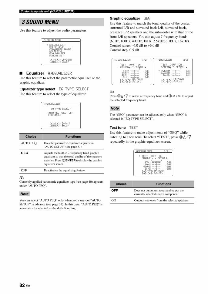
Customizing this unit (MANUAL SETUP)
Use this feature to adjust the audio parameters.
Equalizer A)EQUALIZER
Use this feature to select the parametric equalizer or the graphic equalizer.
Equalizer type select EQ TYPE SELECT
Use this feature to select the type of equalizer.
yCurrently applied parametric equalizer type (see page 40) appears under “AUTO PEQ”.
You can select “AUTO PEQ” only when you carry out “AUTO SETUP” in advance (see page 37). In this case, “AUTO PEQ” is automatically selected as the default setting.
Graphic equalizer GEQ
Use this feature to match the tonal quality of the center, surround L/R and surround back L/R, surround back, presence L/R speakers and the subwoofer with that of the front L/R speakers. You can adjust 7 frequency bands (63Hz, 160Hz, 400Hz, 1kHz, 2.5kHz, 6.3kHz, 16kHz).Control range: –6.0 dB to +6.0 dBControl step: 0.5 dB
yPress 3k / n to select a frequency band and 3l / h to adjust the selected frequency band.
The “GEQ” parameter can be adjusted only when “GEQ” is selected in “EQ TYPE SELECT”.
Test tone TEST
Use this feature to make adjustments of “GEQ” while listening to a test tone. To select “TEST”, press 3k / n repeatedly in the graphic equalizer screen.
3 SOUND MENU
Choice Functions
AUTO PEQ Uses the parametric equalizer adjusted in “AUTO SETUP” (see page 37).
GEQ Adjusts the built-in 7-frequency band graphic equalizer so that the tonal quality of the speakers matches. Press 3ENTER to display the graphic equalizer screen.
OFF Deactivates the equalizing feature.
Note
[]/[]:[ENTER]:
[ p
3 SOUND MENU
A)EQUALIZERB)LFE LEVELC)DYNAMIC RANGED)LIPSYNCE)AUDIO SETF)HDMI SET
UP/DOWNEnter
.
[p]/[[]:[ENTER]:
A)EQUALIZER
EQ TYPE SELECT
AUTO PEQ >GEQ OFF[NATURAL]
SelectEnter
Note
Choice Functions
OFF Does not output test tones and output the currently selected source component.
ON Outputs test tones from the selected speakers.
[]/[]:[p]/[[]:
[ p
A)EQUALIZER 1/2
TEST >OFF ONCHANNEL;;;;FRONT L
63Hz 0dB160Hz 0dB400Hz 0dB1kHz 0dB
UP/DOWNSelect
.
[]/[]:[p]/[[]:
[ p
A)EQUALIZER 2/2
TEST >OFF ONCHANNEL;;;;FRONT L
2.5kHz 0dB6.3kHz 0dB16kHz 0dB
UP/DOWNAdjust
.
[]/[]:[p]/[[]:
[ pA)EQUALIZER 1/2
TEST >OFF ONCHANNEL;;;;FRONT L
63Hz 0dB160Hz 0dB400Hz 0dB1kHz 0dB
UP/DOWNSelect
.
82 En

Customizing this unit (MANUAL SETUP)A
DVA
NC
ED
O
PE
RA
TIO
NE
ng
lish
Low-frequency effect level B)LFE LEVEL
Use this feature to adjust the output level of the LFE (low-frequency effect) channel according to the capacity of your subwoofer or headphones. The LFE channel carries low-frequency special effects which are only added to certain scenes. This setting is effective only when this unit decodes bitstream signals.Control range: –20 to 0 dBControl step: 1 dB
Speakers SPEAKER
Adjusts the speaker LFE level.
Headphones HEADPHONE
Adjusts the headphone LFE level.
Depending on the settings of “LFE/BASS OUT” (see page 77), some signals may not be output at the SUBWOOFER PRE OUT jack.
Dynamic range C)DYNAMIC RANGE
Use this feature to select the amount of dynamic range compression to be applied to your speakers or headphones. This setting is effective only when this unit is decoding bitstream signals.
Speakers SPEAKER
Adjusts the dynamic range compression for the speakers.
Headphones HEADPHONE
Adjusts the dynamic range compression for the headphones.
Note
[]/[]:[p]/[[]:
[ p
B)LFE LEVEL
SPEAKER;;;;;;0dBHEADPHONE;;;;0dB
UP/DOWNAdjust
.
Choice Functions
MIN/AUTO • MIN: Adjusts the dynamic range to narrow when this unit is decoding bitstream signals (except Dolby TrueHD).
• AUTO: Adjusts the dynamic range according to the instruction of the input source signals when this unit is decoding Dolby TrueHD signals.
STD Adjusts the dynamic range to medium. When this unit is decoding Dolby TrueHD signals, the dynamic range control is always active regardless of the instruction of the input source signals.
MAX Preserves the greatest amount of dynamic range.
[]/[]:[p]/[[]:
[ p
C)DYNAMIC RANGE
SPEAKER;;;;;;;;;MAXHEADPHONE;;;;;;;MAX
UP/DOWNSelect
.
83 En
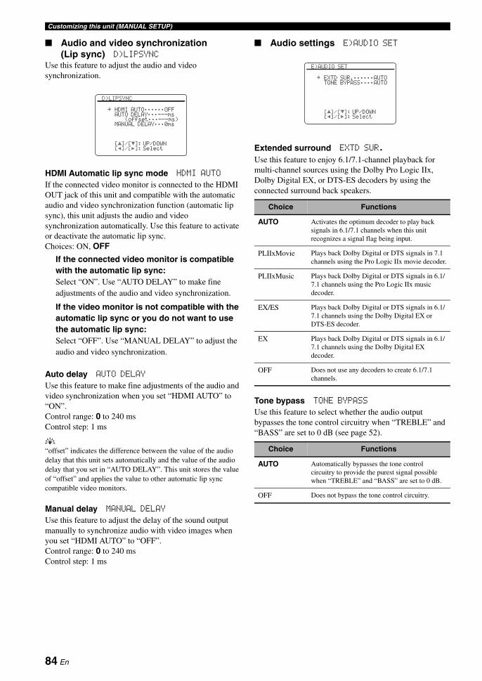
Customizing this unit (MANUAL SETUP)
Audio and video synchronization (Lip sync) D)LIPSYNC
Use this feature to adjust the audio and video synchronization.
HDMI Automatic lip sync mode HDMI AUTO
If the connected video monitor is connected to the HDMI OUT jack of this unit and compatible with the automatic audio and video synchronization function (automatic lip sync), this unit adjusts the audio and video synchronization automatically. Use this feature to activate or deactivate the automatic lip sync.Choices: ON, OFF
If the connected video monitor is compatible with the automatic lip sync:Select “ON”. Use “AUTO DELAY” to make fine adjustments of the audio and video synchronization.
If the video monitor is not compatible with the automatic lip sync or you do not want to use the automatic lip sync:Select “OFF”. Use “MANUAL DELAY” to adjust the audio and video synchronization.
Auto delay AUTO DELAY
Use this feature to make fine adjustments of the audio and video synchronization when you set “HDMI AUTO” to “ON”.Control range: 0 to 240 msControl step: 1 ms
y“offset” indicates the difference between the value of the audio delay that this unit sets automatically and the value of the audio delay that you set in “AUTO DELAY”. This unit stores the value of “offset” and applies the value to other automatic lip sync compatible video monitors.
Manual delay MANUAL DELAY
Use this feature to adjust the delay of the sound output manually to synchronize audio with video images when you set “HDMI AUTO” to “OFF”.Control range: 0 to 240 msControl step: 1 ms
Audio settings E)AUDIO SET
Extended surround EXTD SUR.
Use this feature to enjoy 6.1/7.1-channel playback for multi-channel sources using the Dolby Pro Logic IIx, Dolby Digital EX, or DTS-ES decoders by using the connected surround back speakers.
Tone bypass TONE BYPASS
Use this feature to select whether the audio output bypasses the tone control circuitry when “TREBLE” and “BASS” are set to 0 dB (see page 52).
[]/[]:[p]/[[]:
[ p
D)LIPSYNC
HDMI AUTO;;;;;;OFFAUTO DELAY;;;---ms
(offset;;;---ms)MANUAL DELAY;;;0ms
UP/DOWNSelect
.
Choice Functions
AUTO Activates the optimum decoder to play back signals in 6.1/7.1 channels when this unit recognizes a signal flag being input.
PLIIxMovie Plays back Dolby Digital or DTS signals in 7.1 channels using the Pro Logic IIx movie decoder.
PLIIxMusic Plays back Dolby Digital or DTS signals in 6.1/7.1 channels using the Pro Logic IIx music decoder.
EX/ES Plays back Dolby Digital or DTS signals in 6.1/7.1 channels using the Dolby Digital EX or DTS-ES decoder.
EX Plays back Dolby Digital or DTS signals in 6.1/7.1 channels using the Dolby Digital EX decoder.
OFF Does not use any decoders to create 6.1/7.1 channels.
Choice Functions
AUTO Automatically bypasses the tone control circuitry to provide the purest signal possible when “TREBLE” and “BASS” are set to 0 dB.
OFF Does not bypass the tone control circuitry.
[]/[]:[p]/[[]:
[ p
E)AUDIO SET
EXTD SUR.;;;;;;AUTOTONE BYPASS;;;;AUTO
UP/DOWNSelect
.
84 En

Customizing this unit (MANUAL SETUP)A
DVA
NC
ED
O
PE
RA
TIO
NE
ng
lish
HDMI set F)HDMI SET
Use this feature to select the component to play back HDMI audio signals.
Support audio SUPPORT AUDIO
Use this feature to select whether to play back HDMI audio signals on this unit or on another HDMI component connected to the HDMI OUT jack on the rear panel of this unit.
• This unit transmits audio and video signals input at the HDMI input jacks to the HDMI OUT jack only when this unit is turned on even if “SUPPORT AUDIO” is set to “OTHER”.
• Available audio/video signals depend on the specification of the connected video monitor. Refer to the instruction manual of each connected component.
Use this menu to adjust the parameters of each input source.
Some parameters described above may not be available for all input sources and some parameters are only available for specific input sources.
Choice Functions
RX-V1800 Plays back HDMI audio signals on this unit. The HDMI audio signals input at the HDMI input jacks of this unit are not output to the HDMI component connected to the HDMI OUT jack on the rear panel of this unit.
OTHER Plays back HDMI audio signals on another HDMI component connected to the HDMI OUT jack.
Notes
[p]/[[]:[ENTER]:
F)HDMI SET
SUPPORT AUDIORX-V1800
SelectReturn
4 INPUT MENU
Input source Parameter
A)TUNER INPUT RENAMEVOL. TRIM
B)MULTI CH INPUT RENAMEVOL. TRIMBGVINPUT CHFRONT
C)PHONOD)CDE)CD-RF)MD/TAPEG)BD/HD DVDH)DVDI)DTV/CBLJ)DVRK)VCRL)V-AUX
I/O ASSIGNMENTINPUT RENAMEVOL. TRIMDECODER MODE
M)DOCK INPUT RENAMEVOL. TRIMSTANDBY CHARGE
Note
[]/[]:[ENTER]:
[ p
4 INPUT MENU 1/2
A) TUNERB) MULTI CHC) PHONOD) CDE) CD-RF) MD/TAPEG) BD/HD DVD
UP/DOWNEnter
.
[]/[]:[ENTER]:
[ p
4 INPUT MENU 2/2
H) DVDI) DTV/CBLJ) DVRK) VCRL) V-AUXM) DOCK
UP/DOWNEnter
.
85 En

Customizing this unit (MANUAL SETUP)
Input/output assignmentI/O ASSIGNMENT
Use this feature to assign the input/output jacks according to the component to be used if the initial settings of this unit do not correspond to your needs. Change the parameter to reassign the respective jacks and effectively connect more components.Once the input/output jacks are reassigned, you can select the corresponding component by using the C INPUT selector on the front panel (or the input selector buttons on the remote control).
y• “NONE” appears in the OSD when any input source is not
assigned to the input/output jack.• You cannot select a specific item more than once for the same
type of jack.• An asterisk (*) appears to the right of the input/output jack
names that have been changed from their previous settings.• The currently assigned input source for the selected input/
output jack appears in the OSD (“Current ( DTV/CBL )” in the display example above).
Input rename INPUT RENAME
Use this feature to change the name of the input source that appears in the OSD and in the front panel display.
yYou can also change the name of the input source that appears in the display window (A) on the remote control. Refer to “Changing source names in the display window” on page 102.
1 Press 3l / h to place the “_” (underscore) under the space or the character you want to edit.
2 Press 3k / n to select the character you want to use and then press 3l / h to move to the next space.
• You can use up to 9 characters for each input.• Press 3n to change the character in the following order,
or press 3k to go in the reverse order: A to Z, 0 to 9, a to z, symbols (#, *, –, +, etc.), space.
3 Repeat steps 1 through 2 to rename each input source.
4 Press 3ENTER to complete.
Volume trim VOL. TRIM
Use this feature to adjust the level of the signal input at each jack. This feature is useful if you want to balance the level of each input source to avoid sudden changes in volume when switching between input sources.Control range: –6.0 dB to +6.0 dBControl step: 0.5 dBInitial setting: 0.0 dB
yThis parameter also affects the signals output at the audio ZONE OUT jacks.
Decoder mode DECODER MODE
Use this feature to switch the decoder mode. You can designate the reassigned digital input jacks for DTS signals.
[p]/[[]:[ENTER]:
J) DVR
COMPONENT IN;;;[C]*COAXIAL IN;;;;;(3)OPTICAL IN;;;;NONEOPTICAL OUT;;;NONEHDMI IN;;;;;;;;[4]
Current ( DTV/CBL )SelectEnter
.
[p]/[[]:[ ]/[ ]:[ENTER]:
[RETURN]:
[ p
A) TUNER
INPUT RENAME
TUNER . TUNER
PositionCharacterEnterReturn
Notes
Choice Functions
AUTO Automatically detects digital audio signal input types and selects the appropriate decoder.
DTS Activates the DTS decoder when digital audio signals are input.
[]/[]:[p]/[[]:
[ p
A) TUNER
INPUT RENAMEVOL. TRIM;;;;+6.0dB
UP/DOWNAdjust
.
[]/[]:[p]/[[]:
[ p
D) CD
I/O ASSIGNMENTINPUT RENAMEVOL. TRIM;;;;;0.0dBDECODER MODE;;;AUTO
UP/DOWNSelect
.
86 En

Customizing this unit (MANUAL SETUP)A
DVA
NC
ED
O
PE
RA
TIO
NE
ng
lish
Charge on standby STANDBY CHARGE
Use this feature to select whether this unit charges the battery of the stationed iPod or not when this unit is in the standby mode (see page 61).
Multi-channel input BGV BGV
Use this feature to select the video source played in the background of the sources input at the MULTI CH INPUT jacks.
Input channels INPUT CH
Use this setting to select the number of channels input from an external decoder (see page 30).Choice: 6CH, 8CH
If the connected component outputs discrete 6-channel audio signals:Select “6CH”.
If the connected component outputs discrete 8-channel audio signals:Select “8CH”. Also set “FRONT” (see below) to the analog audio jacks at which the front left and right channel signals output from the connected component are input.
If “AMP” is set to “[SP1]”, “[SP2]” or “BOTH” (see page 91), no sound is output from the surround back speakers even if you select “8CH”. In this case, select “6CH” and set the output setting of the external component to 6 channels.
Front left and right channels input jack FRONT
If you selected “8CH” in “INPUT CH”, you can select the analog audio jacks at which the front left and right channel signals output from the connected external decoder is input.Choices: CD, CD-R, MD/TAPE, BD/HD DVD, DVD,
DTV/CBL, VCR, DVR, V-AUX
“FRONT” parameter appears only when you set “INPUT CH” to “8CH”.
Choice Functions
AUTO Charges the battery of the stationed iPod when this unit is turned on and in the standby mode.
OFF Charges the battery of the stationed iPod only when this unit is turned on.
Choice Functions
LAST Automatically selects the last selected video source as the background video source.
BD/HD DVD, DTV/CBL, DVD, DVR, VCR, V-AUX
Selects the corresponding input source as the background video source.
OFF Does not play the video source in the background.
[]/[]:[ENTER]:
[ p
B) MULTI CH
INPUT RENAMEVOL. TRIM;;;;;0.0dBBGV;;;;;;;;;;;;LASTINPUT CH;;;;;;;;6CH
UP/DOWNSelect
.
Note
Note
[]/[]:[ENTER]:
[ p
B) MULTI CH
INPUT RENAMEVOL. TRIM;;;;;0.0dBBGV;;;;;;;;;;;;LASTINPUT CH;;;;;;;;6CH
UP/DOWNSelect
.
[]/[]:[ENTER]:
[ p
B) MULTI CH
INPUT RENAMEVOL. TRIM;;;;;0.0dBBGV;;;;;;;;;;;;LASTINPUT CH;;;;;;;;8CHFRONT;;;;;BD/HD DVD
UP/DOWNSelect
.
87 En
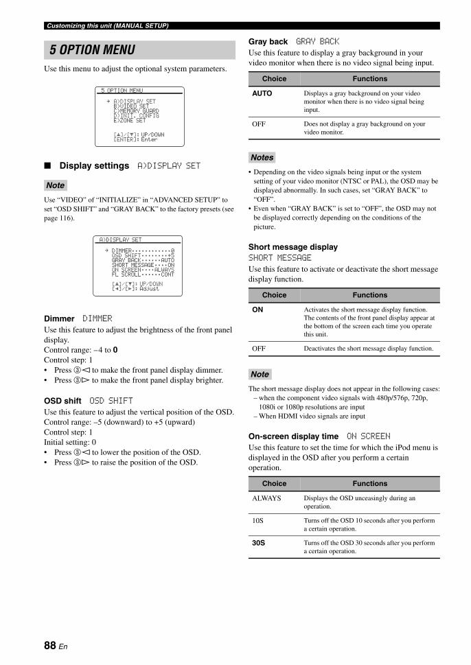
Customizing this unit (MANUAL SETUP)
Use this menu to adjust the optional system parameters.
Display settings A)DISPLAY SET
Use “VIDEO” of “INITIALIZE” in “ADVANCED SETUP” to set “OSD SHIFT” and “GRAY BACK” to the factory presets (see page 116).
Dimmer DIMMER
Use this feature to adjust the brightness of the front panel display.Control range: –4 to 0Control step: 1• Press 3l to make the front panel display dimmer.• Press 3h to make the front panel display brighter.
OSD shift OSD SHIFT
Use this feature to adjust the vertical position of the OSD.Control range: –5 (downward) to +5 (upward)Control step: 1Initial setting: 0• Press 3l to lower the position of the OSD.• Press 3h to raise the position of the OSD.
Gray back GRAY BACK
Use this feature to display a gray background in your video monitor when there is no video signal being input.
• Depending on the video signals being input or the system setting of your video monitor (NTSC or PAL), the OSD may be displayed abnormally. In such cases, set “GRAY BACK” to “OFF”.
• Even when “GRAY BACK” is set to “OFF”, the OSD may not be displayed correctly depending on the conditions of the picture.
Short message displaySHORT MESSAGE
Use this feature to activate or deactivate the short message display function.
The short message display does not appear in the following cases:– when the component video signals with 480p/576p, 720p,
1080i or 1080p resolutions are input– When HDMI video signals are input
On-screen display time ON SCREEN
Use this feature to set the time for which the iPod menu is displayed in the OSD after you perform a certain operation.
5 OPTION MENU
Note
[]/[]:[ENTER]:
[ p
5 OPTION MENU
A)DISPLAY SETB)VIDEO SETC)MEMORY GUARDD)INIT. CONFIGE)ZONE SET
UP/DOWNEnter
.
[]/[]:[p]/[[]:
[ p
A)DISPLAY SET
DIMMER;;;;;;;;;;;;0OSD SHIFT;;;;;;;;+5GRAY BACK;;;;;;AUTOSHORT MESSAGE;;;;ONON SCREEN;;;;ALWAYSFL SCROLL;;;;;;CONT
UP/DOWNAdjust
.
Choice Functions
AUTO Displays a gray background on your video monitor when there is no video signal being input.
OFF Does not display a gray background on your video monitor.
Notes
Choice Functions
ON Activates the short message display function. The contents of the front panel display appear at the bottom of the screen each time you operate this unit.
OFF Deactivates the short message display function.
Note
Choice Functions
ALWAYS Displays the OSD unceasingly during an operation.
10S Turns off the OSD 10 seconds after you perform a certain operation.
30S Turns off the OSD 30 seconds after you perform a certain operation.
88 En
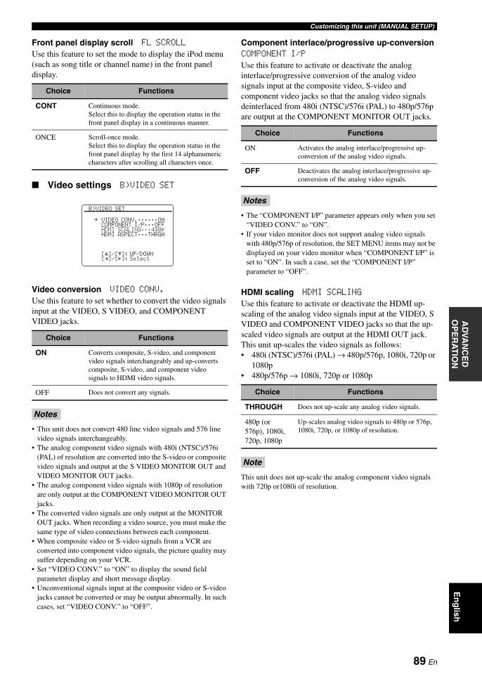
Customizing this unit (MANUAL SETUP)A
DVA
NC
ED
O
PE
RA
TIO
NE
ng
lish
Front panel display scroll FL SCROLL
Use this feature to set the mode to display the iPod menu (such as song title or channel name) in the front panel display.
Video settings B)VIDEO SET
Video conversion VIDEO CONV.
Use this feature to set whether to convert the video signals input at the VIDEO, S VIDEO, and COMPONENT VIDEO jacks.
• This unit does not convert 480 line video signals and 576 line video signals interchangeably.
• The analog component video signals with 480i (NTSC)/576i (PAL) of resolution are converted into the S-video or composite video signals and output at the S VIDEO MONITOR OUT and VIDEO MONITOR OUT jacks.
• The analog component video signals with 1080p of resolution are only output at the COMPONENT VIDEO MONITOR OUT jacks.
• The converted video signals are only output at the MONITOR OUT jacks. When recording a video source, you must make the same type of video connections between each component.
• When composite video or S-video signals from a VCR are converted into component video signals, the picture quality may suffer depending on your VCR.
• Set “VIDEO CONV.” to “ON” to display the sound field parameter display and short message display.
• Unconventional signals input at the composite video or S-video jacks cannot be converted or may be output abnormally. In such cases, set “VIDEO CONV.” to “OFF”.
Component interlace/progressive up-conversionCOMPONENT I/P
Use this feature to activate or deactivate the analog interlace/progressive conversion of the analog video signals input at the composite video, S-video and component video jacks so that the analog video signals deinterlaced from 480i (NTSC)/576i (PAL) to 480p/576p are output at the COMPONENT MONITOR OUT jacks.
• The “COMPONENT I/P” parameter appears only when you set “VIDEO CONV.” to “ON”.
• If your video monitor does not support analog video signals with 480p/576p of resolution, the SET MENU items may not be displayed on your video monitor when “COMPONENT I/P” is set to “ON”. In such a case, set the “COMPONENT I/P” parameter to “OFF”.
HDMI scaling HDMI SCALING
Use this feature to activate or deactivate the HDMI up-scaling of the analog video signals input at the VIDEO, S VIDEO and COMPONENT VIDEO jacks so that the up-scaled video signals are output at the HDMI OUT jack.This unit up-scales the video signals as follows:• 480i (NTSC)/576i (PAL) → 480p/576p, 1080i, 720p or
1080p• 480p/576p → 1080i, 720p or 1080p
This unit does not up-scale the analog component video signals with 720p or1080i of resolution.
Choice Functions
CONT Continuous mode.Select this to display the operation status in the front panel display in a continuous manner.
ONCE Scroll-once mode.Select this to display the operation status in the front panel display by the first 14 alphanumeric characters after scrolling all characters once.
Choice Functions
ON Converts composite, S-video, and component video signals interchangeably and up-converts composite, S-video, and component video signals to HDMI video signals.
OFF Does not convert any signals.
Notes
[]/[]:[p]/[[]:
[ p
B)VIDEO SET
VIDEO CONV.;;;;;;ONCOMPONENT I/P;;;OFFHDMI SCALING;;;480pHDMI ASPECT;;;THRGH
UP/DOWNSelect
.
Choice Functions
ON Activates the analog interlace/progressive up-conversion of the analog video signals.
OFF Deactivates the analog interlace/progressive up-conversion of the analog video signals.
Notes
Choice Functions
THROUGH Does not up-scale any analog video signals.
480p (or 576p), 1080i, 720p, 1080p
Up-scales analog video signals to 480p or 576p, 1080i, 720p, or 1080p of resolution.
Note
89 En
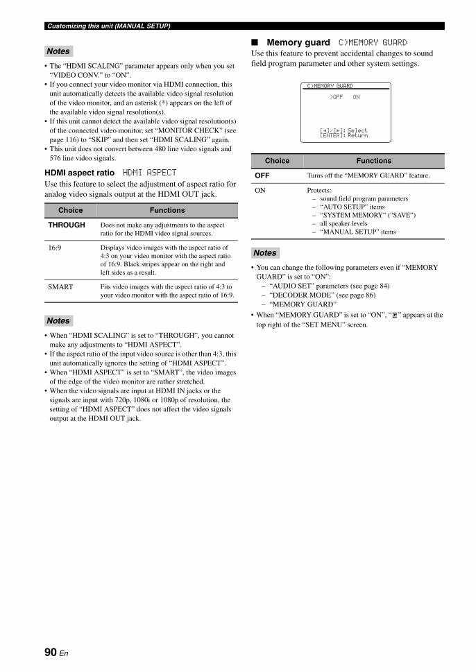
Customizing this unit (MANUAL SETUP)
• The “HDMI SCALING” parameter appears only when you set “VIDEO CONV.” to “ON”.
• If you connect your video monitor via HDMI connection, this unit automatically detects the available video signal resolution of the video monitor, and an asterisk (*) appears on the left of the available video signal resolution(s).
• If this unit cannot detect the available video signal resolution(s) of the connected video monitor, set “MONITOR CHECK” (see page 116) to “SKIP” and then set “HDMI SCALING” again.
• This unit does not convert between 480 line video signals and 576 line video signals.
HDMI aspect ratio HDMI ASPECT
Use this feature to select the adjustment of aspect ratio for analog video signals output at the HDMI OUT jack.
• When “HDMI SCALING” is set to “THROUGH”, you cannot make any adjustments to “HDMI ASPECT”.
• If the aspect ratio of the input video source is other than 4:3, this unit automatically ignores the setting of “HDMI ASPECT”.
• When “HDMI ASPECT” is set to “SMART”, the video images of the edge of the video monitor are rather stretched.
• When the video signals are input at HDMI IN jacks or the signals are input with 720p, 1080i or 1080p of resolution, the setting of “HDMI ASPECT” does not affect the video signals output at the HDMI OUT jack.
Memory guard C)MEMORY GUARD
Use this feature to prevent accidental changes to sound field program parameter and other system settings.
• You can change the following parameters even if “MEMORY GUARD” is set to “ON”:
– “AUDIO SET” parameters (see page 84)– “DECODER MODE” (see page 86)– “MEMORY GUARD”
• When “MEMORY GUARD” is set to “ON”, “ ” appears at the top right of the “SET MENU” screen.
Notes
Choice Functions
THROUGH Does not make any adjustments to the aspect ratio for the HDMI video signal sources.
16:9 Displays video images with the aspect ratio of 4:3 on your video monitor with the aspect ratio of 16:9. Black stripes appear on the right and left sides as a result.
SMART Fits video images with the aspect ratio of 4:3 to your video monitor with the aspect ratio of 16:9.
Notes
Choice Functions
OFF Turns off the “MEMORY GUARD” feature.
ON Protects:– sound field program parameters– “AUTO SETUP” items– “SYSTEM MEMORY” (“SAVE”)– all speaker levels– “MANUAL SETUP” items
Notes
[p]/[[]:[ENTER]:
C)MEMORY GUARD
>OFF ON
SelectReturn
G
90 En

Customizing this unit (MANUAL SETUP)A
DVA
NC
ED
O
PE
RA
TIO
NE
ng
lish
Initial configuration D)INIT. CONFIG
Use this feature to select the settings of the audio input jack select, active decoders and extended surround when you turn on this unit.
Audio select AUDIO SELECT
Use this feature to designate the default audio input jack select setting (see page 43) for the input sources connected to the DIGITAL INPUT jacks when you turn on the power of this unit.
Decoder mode DECODER MODE
Use this feature to designate the default decoder mode (see page 86) for the input sources connected to the DIGITAL INPUT jacks when you turn on the power of this unit.
Extended surround EXTD SUR.
Use this feature to designate the extended decoder mode (see page 84) for the input sources connected to the DIGITAL INPUT jacks when you turn on the power of this unit.
Zone set E)ZONE SET
Use this feature to set the items related in Zone 2 or Zone 3.
Setting zoneSelect the zone to set up “AMP”, “VOLUME”, “MAX VOL.” and “INIT. VOL.”.
Zone 2/Zone 3 amplifier AMP
Use this feature to select how the Zone 2 or Zone 3 speakers are amplified. This parameter also effects the speaker settings and the sound output of sound field programs in the main zone.Choices: EXT, [SP1], [SP2], BOTH
When the speakers in Zone 2 or Zone 3 are connected to the external amplifier, and the external amplifier is connected to the ZONE OUT (ZONE 2 or ZONE 3) jacks of this unit:Select “EXT”. See “Using external amplifiers” on page 108 for details.
When “BI-AMP” is set to “ON” in “ADVANCED SETUP” (see page 116), you can only set “AMP” to “EXT” in “ZONE 2” or “ZONE 3”.
When the speakers in Zone 2 or Zone 3 is connected to the SP1 speaker terminals of this unit directly:Select “[SP1]”. See “Using the internal amplifiers of this unit” on page 109 for details.
When you set “AMP” to “[SP1]” in “ZONE 2” or “ZONE 3” and the corresponding zone is turned on, no sound is output from the surround back speakers.
Choice Functions
AUTO Automatically detects the type of audio input signals and selects the appropriate audio input jack select setting.
LAST Automatically selects the last audio input jack select setting used for the connected input source.
Choice Functions
AUTO Automatically detects the type of input signals and select the appropriate decoder mode setting.
LAST Automatically selects the last decoder mode setting used for the connected input source.
Choice Functions
AUTO Automatically detects the digital audio input signals and activates the appropriate decoder.
LAST Automatically selects the last decoder mode set for “EXTD SUR.” in “SOUND MENU”.
[p]/[[]:[ENTER]:
D)INIT. CONFIG
AUDIO SELECT;;AUTODECODER MODE;;AUTOEXTD SUR.;;;;;AUTO
SelectReturn
.
Choice Functions
ZONE2 Sets the “ZONE SET” parameters for Zone 2.
ZONE3 Sets the “ZONE SET” parameters for Zone 3.
Note
Note
[]/[]:[p]/[[]:
[ p
E)ZONE SET
>ZONE2 ZONE3
AMP;;;;;;;;;;;;EXTVOLUME;;;;;;;;;VARMAX VOL.;;;-30.0dBINIT. VOL.;+16.5dB
UP/DOWNSelect
.
91 En
Customizing this unit (MANUAL SETUP)
When the speakers in Zone 2 or Zone 3 is connected to the SP2 speaker terminals of this unit directly:Select “[SP2]”. See “Using the internal amplifiers of this unit” on page 109 for details.
When you set “AMP” to “[SP2]” in “ZONE 2” or “ZONE 3” and the corresponding zone is turned on, no sound is output from the surround speakers.
If the speakers in Zone 2 or Zone 3 are connected to both the SP1 and SP2 speaker terminals (for example, the speakers are connected via the bi-amplifier connection, or there are four speakers in a room) or if you want to play back the same source in Zone 2 and Zone 3 simultaneously:Select “BOTH”. See “Using the internal amplifiers of this unit” on page 109 for details.
• When you set “AMP” to “BOTH” in “ZONE 2” or “ZONE 3”, you can only set “AMP” to “EXT” in the other zone setting.
• When you set “AMP” to “BOTH” in “ZONE 2” or “ZONE 3” and the corresponding zone is turned on, no sound is output from both the surround and surround back speakers.
Zone 2/Zone 3 volume VOLUME
Use this feature to select whether this unit controls the volume level of the audio signals output at the ZONE OUT (ZONE 2 or ZONE 3) jacks when you set “AMP” to “EXT” (see page 91).Choices: VAR, FIX
When you want to control the volume level of the selected zone on this unit:Select “VAR”. You can adjust the ZONE OUT (ZONE 2 or ZONE 3) volume level simultaneously with BVOLUME +/– on the remote control.
When you want to control the volume level of the selected zone on the external amplifier:Select “FIX”. This unit fixes the ZONE OUT (ZONE 2 or ZONE 3) volume level to a standard line level.
Zone 2/Zone 3 maximum volume MAX VOL.
Use this feature to set the maximum volume level in the Zone 2 or Zone 3.Control range: –30.0 dB to +15.0 dB, +16.5 dBControl step: 5.0 dB
The “MAX VOL.” setting takes priority over the “INIT. VOL.” setting. For example, “INIT. VOL.” is set to –20.0 dB and then “MAX VOL.” is set to –30.0 dB, the volume level is automatically set to –30.0 dB when you turn on the power of this unit next time.
Zone 2/Zone 3 initial volume INIT. VOL.
Use this feature to set the volume level of Zone 2 or Zone 3 when the power of Zone 2 or Zone 3 is turned on.Choices: OFF, MUTE, –80.0 dB to +16.5 dBControl step: 0.5 dB
The “MAX VOL.” setting takes priority over the “INIT. VOL.” setting.
Note
Notes
Note
Note
92 En
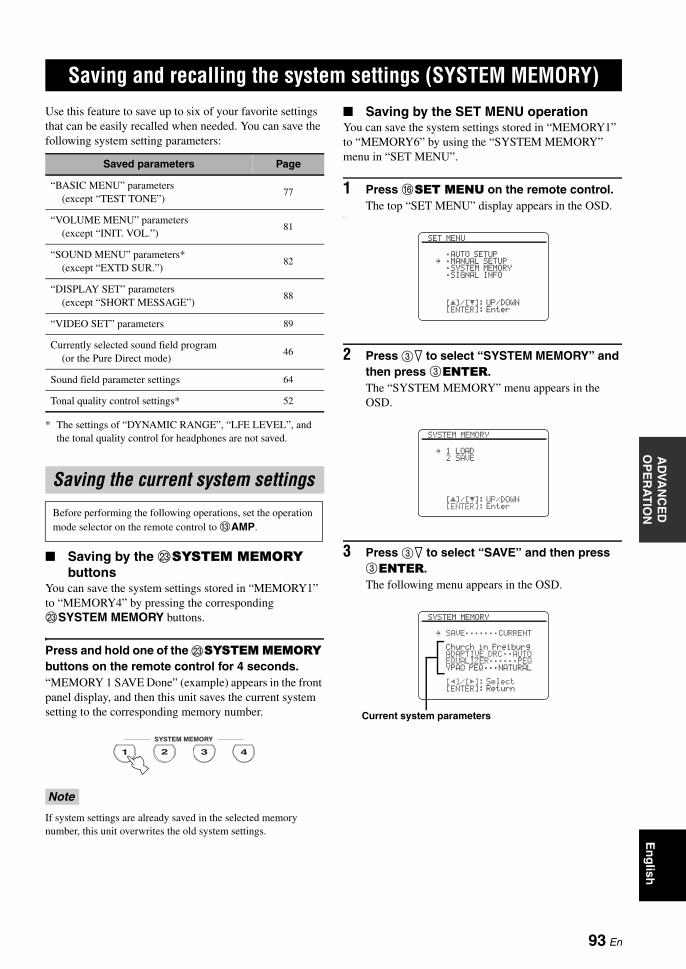
AD
VAN
CE
D
OP
ER
AT
ION
En
glish
Use this feature to save up to six of your favorite settings that can be easily recalled when needed. You can save the following system setting parameters:
* The settings of “DYNAMIC RANGE”, “LFE LEVEL”, and the tonal quality control for headphones are not saved.
Saving by the MSYSTEM MEMORY buttons
You can save the system settings stored in “MEMORY1” to “MEMORY4” by pressing the corresponding MSYSTEM MEMORY buttons.
Press and hold one of the MSYSTEM MEMORY buttons on the remote control for 4 seconds.“MEMORY 1 SAVE Done” (example) appears in the front panel display, and then this unit saves the current system setting to the corresponding memory number.
If system settings are already saved in the selected memory number, this unit overwrites the old system settings.
Saving by the SET MENU operationYou can save the system settings stored in “MEMORY1” to “MEMORY6” by using the “SYSTEM MEMORY” menu in “SET MENU”.
1 Press FSET MENU on the remote control.The top “SET MENU” display appears in the OSD.
o
2 Press 3n to select “SYSTEM MEMORY” and then press 3ENTER.The “SYSTEM MEMORY” menu appears in the OSD.
3 Press 3n to select “SAVE” and then press 3ENTER.The following menu appears in the OSD.
Saving and recalling the system settings (SYSTEM MEMORY)
Saved parameters Page
“BASIC MENU” parameters(except “TEST TONE”)
77
“VOLUME MENU” parameters(except “INIT. VOL.”)
81
“SOUND MENU” parameters*(except “EXTD SUR.”)
82
“DISPLAY SET” parameters(except “SHORT MESSAGE”)
88
“VIDEO SET” parameters 89
Currently selected sound field program(or the Pure Direct mode)
46
Sound field parameter settings 64
Tonal quality control settings* 52
Saving the current system settings
Before performing the following operations, set the operation mode selector on the remote control to CAMP.
Note
4321
SYSTEM MEMORY
[]/[]:[ENTER]:
[ p
SET MENU
;AUTO SETUP;MANUAL SETUP;SYSTEM MEMORY;SIGNAL INFO
UP/DOWNEnter
.
[]/[]:[ENTER]:
[ p
SYSTEM MEMORY
1 LOAD2 SAVE
UP/DOWNEnter
.
[p]/[[]:[ENTER]:
SYSTEM MEMORY
SAVE;;;;;;;CURRENT
Church in FreiburgADAPTIVE DRC;;AUTOEQUALIZER;;;;;;PEQYPAO PEQ;;;NATURAL
SelectReturn
.
Current system parameters
93 En

Saving and recalling the system settings (SYSTEM MEMORY)
4 Press 3l / h repeatedly to select the desired memory number (“MEMORY1” to “MEMORY6”).
y• If system settings are already stored in the selected
memory number, the stored system parameter settings appear in the menu screen. “EMPTY” appears in the menu screen if no system settings are stored in the selected memory number.
• If system settings are already saved in the selected memory number, this unit overwrite the old system settings.
• If you save the system settings to “MEMORY1” to “MEMORY4”, you can load the stored settings by pressing the corresponding MSYSTEM MEMORY buttons (see page 94).
5 Press 3ENTER to save the current system settings to the selected memory number.
6 Press FSET MENU again to exit from “SET MENU”.
Loading by the MSYSTEM MEMORY buttons
You can recall the system settings stored in “MEMORY1” to “MEMORY4” by pressing the corresponding MSYSTEM MEMORY buttons.
1 Press one of the MSYSTEM MEMORY buttons on the remote control to select the desired memory number.“MEMORY 1 LOAD” (example) appears in the front panel display.
y“EMPTY” appears in the menu screen if no system settings are stored in the selected memory number.
2 Press the selected MSYSTEM MEMORY button once more to confirm the selection.This unit loads the settings stored in the selected memory number.
Loading by the SET MENU operation
1 Press FSET MENU on the remote control.The top “SET MENU” display appears in the OSD.
2 Press 3n to select “SYSTEM MEMORY” and then press 3ENTER.The “SYSTEM MEMORY” menu appears in the OSD.
3 Press 3ENTER to select “LOAD”.The following menu appears in the OSD.
4 Press 3l / h repeatedly to select the desired memory number where the system settings are stored and then press 3ENTER.This unit loads the selected system settings.
5 Press FSET MENU to exit from “SET MENU”.
Loading the stored system settings
• Before performing the following operations, set the operation mode selector on the remote control to CAMP.
• This unit overwrites the stored settings to the current settings of this unit. If you do not want to erase the current settings, save the current settings to any SYSTEM MEMORY number in advance.
[p]/[[]:[ENTER]:
SYSTEM MEMORY
SAVE;;;;;;;MEMORY1
DramaADAPTIVE DRC;;AUTOEQUALIZER;;;;;;GEQYPAO PEQ;;;;;;NONE
SelectReturn
.
Stored system parameters in the selected memory number
4321
SYSTEM MEMORY
[p]/[[]:[ENTER]:
SYSTEM MEMORY
LOAD;;;;;;;CURRENT
Church in FreiburgADAPTIVE DRC;;AUTOEQUALIZER;;;;;;PEQYPAO PEQ;;;NATURAL
SelectReturn
.
[p]/[[]:[ENTER]:
SYSTEM MEMORY
LOAD;;;;;;;MEMORY6
StraightADAPTIVE DRC;;AUTOEQUALIZER;;;;;;PEQYPAO PEQ;;;;;;FLAT
SelectLoad
.
94 En

Saving and recalling the system settings (SYSTEM MEMORY)A
DVA
NC
ED
O
PE
RA
TIO
NE
ng
lish
Example 1: Comparing the results of the automatic setup and manual setup
This unit is equipped with three types of parametric equalizer settings (see page 40), and you can also make your customized configuration of the sound settings of this unit by using the “MANUAL SETUP” parameters (see page 72). To compare the results of the automatic setup or your manual configuration, use the MSYSTEM MEMORY buttons.
Saving each setting
Carry out the following procedure when all the parameters are set to default values.
1 Press and hold MSYSTEM MEMORY 1 for 4 seconds.This unit stores the current settings of this unit to “MEMORY1”.
2 Perform the automatic setup.Set “EQ” to “NATURAL”. See page 40 for details.
3 Press and hold MSYSTEM MEMORY 2 for 4 seconds.This unit stores the results of the automatic setup performed in step 2 to “MEMORY2”.
4 Perform the automatic setup again.This time, set “EQ” to “FRONT”.
5 Press and hold MSYSTEM MEMORY 3 for 4 seconds.This unit stores the results of the automatic setup performed in step 4 to “MEMORY3”.
Example 2: Switching the settings for different room environments
The tonal characteristics of the listening room may vary depending on the situations of the room (for example, whether the curtains are open or closed), and the settings of this unit should be arranged for each situation of the room. You can switch between the settings of this unit easily by using MSYSTEM MEMORY buttons.
Saving each setting
1 Close the curtains of the listening room and then perform the automatic setup.See page 37 for details of the automatic setup.
2 Press and hold MSYSTEM MEMORY 1 for 4 seconds.This unit stores the settings for the current room situation (i.e. the curtains are closed) to “MEMORY1”.
3 Open the curtains of the listening room and the perform the automatic setup.
4 Press and hold MSYSTEM MEMORY 2 for 4 seconds.This unit stores the current room situation (i.e. the curtains are open) to “MEMORY2”.
Using examples
Note
4
5 76 8
CLASSICAL LIVE/CLUB ENTERTAIN MOVIE
SYSTEM MEMORY
321
SYSTEM MEMORY 1The current settings of this unit
SYSTEM MEMORY 2The results of the automatic setup (EQ: NATURAL)
SYSTEM MEMORY 3The results of the automatic setup (EQ: FRONT)
4
5 76 8
CLASSICAL LIVE/CLUB ENTERTAIN MOVIE
SYSTEM MEMORY
321
SYSTEM MEMORY 1The settings when the curtains of the listening room are closed
SYSTEM MEMORY 2The settings when the curtains of the listening room are open
95 En

Saving and recalling the system settings (SYSTEM MEMORY)
Example 3: Saving the sound configurations for specific sources
The desired sound configurations are different for each input source. For example, if you use the sound field program “Village Vanguard” for a music source of a live jazz performance, the parameter settings may differ when the input source is a vinyl record or an SACD. You can store the sound settings for each input source.
Saving each setting
ySee page 64 for the sound field program parameter settings.
1 Start playback of the desired live jazz performance recorded on the SACD.
2 Set the sound field program to “Village Vanguard” and then adjust the parameters for the current playback sources.
3 Press and hold MSYSTEM MEMORY 1 for 4 seconds.This unit stores the current sound field program settings to “MEMORY1”.
4 Change the input source to “PHONO” and then start playback of the desired live jazz performance recorded on the vinyl record.
5 Adjust the sound field program parameters for the current playback source.
6 Press and hold MSYSTEM MEMORY 2 for 4 seconds.This unit stores the current sound field program settings to “MEMORY2”.
Example 4: Switching multiple audio and video synchronization settings
If you use two different kinds of video monitors or projectors, and these components are not compatible with the automatic audio and video synchronization feature, you should set “MANUAL DELAY” for each component. You can switch between the different “MANUAL DELAY” settings by using the MSYSTEM MEMORY buttons.
Saving each setting
In the following example, the LCD video monitor and one input component (for example, VCR) are connected to the S VIDEO input jack and S VIDEO MONITOR OUT jack, and the video projector and the other input component (for example, DVD player) are connected to one of the HDMI IN jacks and HDMI OUT jack.
1 Start playback of the desired video source on the connected LCD video monitor and then adjust “MANUAL DELAY” in “SOUND MENU” appropriately (see page 84).
2 Press and hold MSYSTEM MEMORY 1 for 4 seconds.This unit stores the audio and video synchronization settings for the LCD video monitor to “MEMORY 1”.
3 Change the input source to the component connected to one of the HDMI IN jacks and then start playback.
4 Adjust “MANUAL DELAY” in “SOUND MENU” appropriately.
5 Press and hold MSYSTEM MEMORY 2 for 4 seconds.This unit stores the audio and video synchronization settings for the video projector to “MEMORY 2”.
4
5 76 8
CLASSICAL LIVE/CLUB ENTERTAIN MOVIE
SYSTEM MEMORY
321
SYSTEM MEMORY 1The “Village Vanguard” program configured for the SACD sources
SYSTEM MEMORY 2The “Village Vanguard” program configured for the vinyl record sources
Note
4
5 76 8
CLASSICAL LIVE/CLUB ENTERTAIN MOVIE
SYSTEM MEMORY
321
SYSTEM MEMORY 1The settings for the LCD video monitor connected to the S VIDEO MONITOR OUT jack
SYSTEM MEMORY 2The settings for the video projector connected to the HDMI OUT jack
96 En
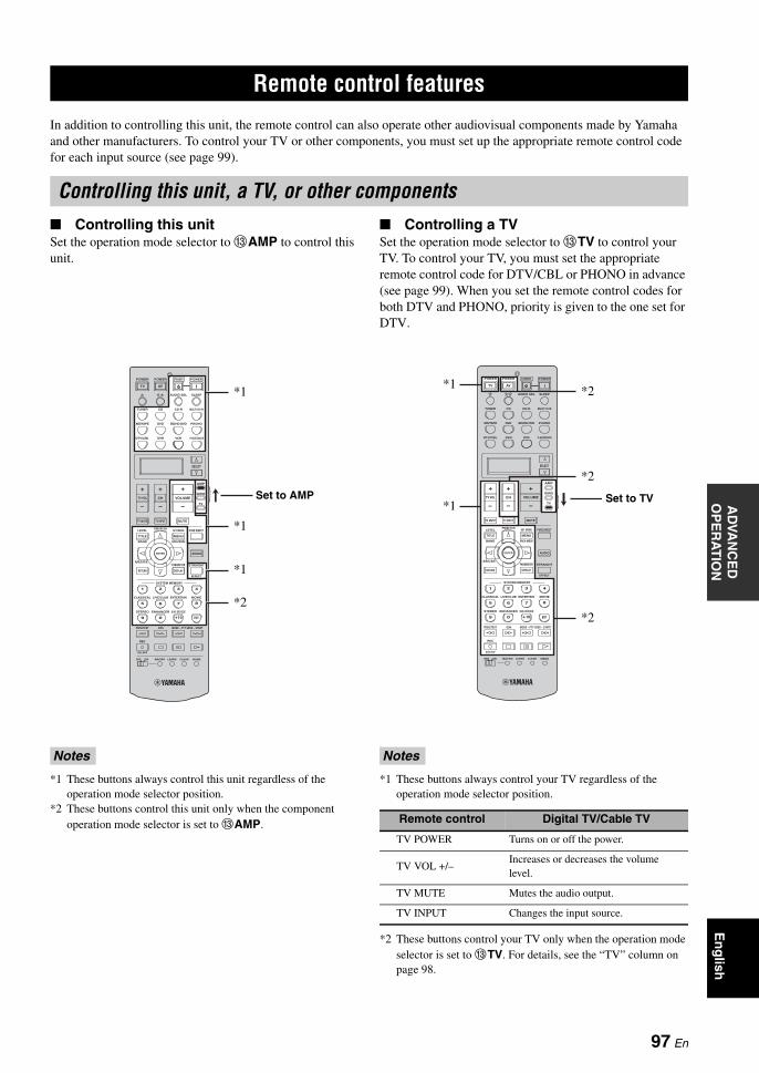
AD
VAN
CE
D
OP
ER
AT
ION
En
glish
In addition to controlling this unit, the remote control can also operate other audiovisual components made by Yamaha and other manufacturers. To control your TV or other components, you must set up the appropriate remote control code for each input source (see page 99).
Controlling this unitSet the operation mode selector to CAMP to control this unit.
*1 These buttons always control this unit regardless of the operation mode selector position.
*2 These buttons control this unit only when the component operation mode selector is set to CAMP.
Controlling a TVSet the operation mode selector to CTV to control your TV. To control your TV, you must set the appropriate remote control code for DTV/CBL or PHONO in advance (see page 99). When you set the remote control codes for both DTV and PHONO, priority is given to the one set for DTV.
*1 These buttons always control your TV regardless of the operation mode selector position.
*2 These buttons control your TV only when the operation mode selector is set to CTV. For details, see the “TV” column on page 98.
Remote control features
Controlling this unit, a TV, or other components
Notes
–
+ +
––
+
ENTER
DISPLAY
AUDIO
MENUTITLE
TV MUTE TV INPUT MUTE
432
ENT+1009
5
1
AVTV
76 8
RETURN
ONOFF CLEARLEARN RENAMEMACRO
REC
DISC SKIP
VOLUMECHTV VOL
EFFECT
PARAMETER STRAIGHTA/B/C/D/E
SRCH MODE
PURE DIRECTPRESET/CH
SET MENU
BAND
LEVEL
CLASSICAL LIVE/CLUB ENTERTAIN MOVIE
SYSTEM MEMORY
SUR. DECODE
FREQ/TEXT EON MODE – PTY SEEK – START
ENHANCERSTEREO
TV
SOURCE
AMP
SELECT
DTV/CBL VCRDVR V-AUX/DOCK
TUNER CD CD-R MULTI CH IN
POWER POWER POWERSTANDBY
SLEEPAUDIO SEL
DVD BD/HD DVD PHONOMD/TAPE
Set to AMP
*1
*1
*1
*2
Notes
Remote control Digital TV/Cable TV
TV POWER Turns on or off the power.
TV VOL +/–Increases or decreases the volume level.
TV MUTE Mutes the audio output.
TV INPUT Changes the input source.
–
+ +
––
+
ENTER
DISPLAY
AUDIO
MENUTITLE
TV MUTE TV INPUT MUTE
432
ENT+1009
5
1
AVTV
76 8
RETURN
ONOFF CLEARLEARN RENAMEMACRO
REC
DISC SKIP
VOLUMECHTV VOL
EFFECT
PARAMETER STRAIGHTA/B/C/D/E
SRCH MODE
PURE DIRECTPRESET/CH
SET MENU
BAND
LEVEL
CLASSICAL LIVE/CLUB ENTERTAIN MOVIE
SYSTEM MEMORY
SUR. DECODE
FREQ/TEXT EON MODE – PTY SEEK – START
ENHANCERSTEREO
TV
SOURCE
AMP
SELECT
DTV/CBL VCRDVR V-AUX/DOCK
TUNER CD CD-R MULTI CH IN
POWER POWER POWERSTANDBY
SLEEPAUDIO SEL
DVD BD/HD DVD PHONOMD/TAPE
Set to TV
*1
*1
*2
*2
*2
97 En

Remote control features
Controlling other componentsSet the operation mode selector to CSOURCE to control other components selected with the input selector buttons (1) or . You must set the appropriate remote control code for each input source in advance (see page 99). The following table shows the function of each control button used to control other components assigned to each input selector button (1) or . Be advised that some buttons may not correctly operate the selected component.
yThe remote control has 14 modes (input areas) to control components so that the remote control can operate up to 14 different components.
*1 This button is operational only when the original remote control supplied with the component has a power button.*2 These buttons operate your video recorder (DVD recorder, etc.) only when you set the appropriate remote control code for DVR (see
page 99).*3 These buttons control your TV only when the operation mode selector is set to TV. For details, see the “TV” column.
–
+ +
––
+
ENTER AUDIO
MENUTITLE
TV MUTE TV INPUT MUTE
AVTV
ENTER
DISPLAY
AUDIO
MENUTITLE
TV MUTE TV INPUT MUTE
432
ENT+1009
5
1
76 8
RETURN
VOLUMECHTV VOL
SRCH MODE
PURE DIRECTPRESET/CH
SET MENU
BAND
LEVEL
TV
SOURCE
AMP
SELECT
DTV/CBL VCRDVR V-AUX/DOCK
TUNER CD CD-R MULTI CH IN
POWER POWER POWERSTANDBY
SLEEPAUDIO SEL
DVD BD/HD DVD PHONOMD/TAPE
ONOFF CLEARLEARN RENAMEMACRO
REC
DISC SKIP
EFFECT
PARAMETER STRAIGHTA/B/C/D/E
SRCH MODE
PURE DIRECTPRESET/CH
SET MENU
BAND
LEVEL
CLASSICAL LIVE/CLUB ENTERTAIN MOVIE
SYSTEM MEMORY
SUR. DECODE
FREQ/TEXT EON MODE – PTY SEEK – START
ENHANCERSTEREO
[1][3][4][5]
[6]
[7][2]
[8][9]
[10]
[11]
Set to SOURCE
Blu-ray Disc/ HD DVD player/ recorder
DVD player/DVD recorder
VCRCable TV/ Satellite tuner
TV LD player CD player MD recorder/CD recorder Tape deck Tuner
[1] AV POWER Power *1 Power *1 Power *1 Power *1 DVR power *2
Power *1 Power *1 Power *1 Power *1 Power *1
[2] CH + TV channel up*3
TV channel up*3 Channel up Channel up Channel up
TV channel up*3
TV channel up*3
TV channel up*3
TV channel up*3
TV channel up*3
CH –TV channel down*3
TV channel down*3 Channel down Channel down Channel down
TV channel down*3
TV channel down*3
TV channel down*3
TV channel down*3
TV channel down*3
[3] TITLE Title Title Title Title Title Band
[4] ENTER Menu enter Menu enter Menu select Menu select
PRESET/CH k Menu up Menu up Menu up Menu upPreset up (1 to 8)
PRESET/CH n Menu down Menu down Menu down Menu downPreset down (1 to 8)
A/B/C/D/E l Menu left Menu left Menu left Menu leftPreset down (A to E)
A/B/C/D/E h Menu right Menu right Menu right Menu right Direction A/BPreset up (A to E)
[5] RETURN Return Return Return Return Return
[6] 1-9, 0, +10 Numeric buttons
Numeric buttons
Numeric buttons
Numeric buttons
Numeric buttons
Numeric buttons
Numeric buttons
Numeric buttons
[7] ll Search backward
Search backward
Search backward
DVR search backward *2
DVR search backward *2
Search backward
Search backward
Search backward
Search backward
hhSearch forward
Search forward
Search forward
DVR search forward *2
DVR search forward *2
Search forward
Search forward
Search forward
Search forward
bSkip backward
Skip backward
Chapter/Skip backward
Skip backward
Skip backward
Direction back
a Skip forward Skip forwardChapter/Skip forward
Skip forward Skip forwardDirection forward
REC/ DISC SKIP
Rec (recorder)
Disc skip (player)Rec (recorder)
Rec DVR rec *2 DVR rec *2 Disc skip Rec Rec
s Stop Stop Stop DVR stop *2 DVR stop *2 Stop Stop Stop Stop
e Pause Pause Pause DVR pause *2 DVR pause *2 Pause Pause Pause Pause
p Play Play Play DVR play *2 DVR play *2 Play Play Play Play
[8] MENU Menu Menu Menu Menu
[9] AUDIO Audio Audio Audio
[10] DISPLAY Display Display Display Display Display Display Display
[11] ENT Enter Enter/recall Enter
Notes
98 En

Remote control featuresA
DVA
NC
ED
O
PE
RA
TIO
NE
ng
lish
Selecting a component to be controlledYou can select a component to be controlled independently of the input source selected with the input selector buttons (1).
Press ASELECT k / n repeatedly to select the desired component.The name of the component to be controlled appears in the display window (A) on the remote control.
Controlling optional components (Option mode)
“OPTN” is an optional component control area that can be programmed with remote control functions independently from any input source. This area is useful for programming commands that are to be used only as a part of a macro function or for components that do not have a valid remote control code.
To select the option mode, press ASELECT n repeatedly until “OPTN” appears in the display window on the remote control.
You cannot set a remote control code for the optional area. See page 101 to program buttons operated within this component control area.
You can control other components by setting the appropriate remote control codes. Codes can be set up for each input area. For a complete list of available remote control codes, refer to “List of remote control codes” at the end of this manual.
The following table shows the default component (Library: component category) and the remote control code for each input area.
Remote control code default settings
You may not be able to operate your Yamaha component even if a Yamaha remote control code is preset as listed above. In this case, try setting another Yamaha remote control code.
Note
SELECT
SELECT
Setting remote control codes
Input areaLibrary
(component category)
ManufacturerDefault code
TAPE — 2700
TUNER Yamaha 2607
TUNER TUNER Yamaha 2602
CD CD Yamaha 2300
CD-R CD-R Yamaha 2400
MULTI CH IN
DVD Yamaha 2100
MD/TAPE MD Yamaha 2500
DVD DVD Yamaha 2100
BD/HD DVD DVD Yamaha 2100
PHONO TV — —
DTV/CBL TV — —
DVR DVR Yamaha 2807
VCR VCR — —
V-AUX/DOCK
TUNER Yamaha 2606
Note
99 En

Remote control features
1 Set the operation mode selector to CSOURCE and then press an input selector button (1), or to select the input area you want to set up.
2 Press and hold LLEARN for about 3 seconds using a ballpoint pen or similar object.The library name (e.g. L;DVD) and the name of the selected input area (e.g. DVD) appear alternately in the display window (A) on the remote control.
y• You can set a remote control code of a different type of
component to an input area. Press 3l / h repeatedly to change the library (component category).Library choices: L;DVD, L;DVR, L;LD, L;CD, L;CDR,
L;MD, L;TAP (tape), L;TUN (tuner), L;AMP, L;TV, L;CAB (cable), L;SAT (satellite), L;VCR
• If you want to setup for another input area, press the input selector button (1) or , or press ASELECT k / n repeatedly to select the input area.
• Be sure to press and hold LLEARN for at least 3 seconds, otherwise the learning process will start.
• If you do not complete each of the following steps within 30 seconds, the setting mode will be automatically canceled. In this case, start over from step 2.
3 Press 3ENTER.The four-digit code set for the selected component appears in the display window (A).
“0000” appears in the display window (A) if no code has been set.
4 Press the numeric buttons (5) to enter the four-digit remote control code for the component you want to use.For a complete list of available remote control codes, refer to “List of remote control codes” at the end of this manual.
5 Press 3ENTER to set the number.“OK” appears in the display window (A) on the remote control if setting is successful.“NG” appears in the display window (A) on the remote control if the setting is unsuccessful. In this case, start over from step 3.
yIf you continuously want to set up another code for another component, press the input selector button (1) or , or ASELECT k / n repeatedly to select the component, then repeat steps 2 through 5.
6 Press LLEARN again to exit from the setup mode.
7 Press 6p (play) or AV POWER to confirm whether you can control your component using the remote control.
yIf operation is not possible and the manufacturer of your component has more than one code, try each of them until you find the correct one.
• “ERROR” appears in the display window (A) on the remote control if you press a button not indicated in the respective step, or when you press more than one button simultaneously.
• The supplied remote control does not contain all possible codes for commercially available audio and video components (including Yamaha components). If operation is not possible with any of the remote control codes, program the new remote control function using the learn feature (see “Programming codes from other remote controls” on page 101) or use the remote control supplied with the component.
• Functions programmed using the learn feature take priority over remote control code functions.
Notes
Note
DTV/CBL VCRDVR V-AUX/DOCK
TUNER CD CD-R MULTI CH IN
DVD BD/HD DVD PHONOMD/TAPETV
SOURCE
AMP
LEARN
Notes
432
ENT+1009
5
1
76 8
CLASSICAL LIVE/CLUB ENTERTAIN MOVIE
SYSTEM MEMORY
SUR. DECODEENHANCERSTEREO
LEARN
AV
POWER
or
100 En
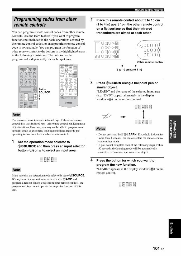
Remote control featuresA
DVA
NC
ED
O
PE
RA
TIO
NE
ng
lish
You can program remote control codes from other remote controls. Use the learn feature if you want to program functions not included in the basic operations covered by the remote control codes, or an appropriate remote control code is not available. You can program the function of other remote control to the buttons in the highlighted areas in the following illustration. The buttons can be programmed independently for each input area.
The remote control transmits infrared rays. If the other remote control also uses infrared rays, this remote control can learn most of its functions. However, you may not be able to program some special signals or extremely long transmissions. Refer to the operating instructions for the other remote control.
1 Set the operation mode selector to CSOURCE and then press an input selector button (1) or to select an input area.
Make sure that the operation mode selector is set to CSOURCE. When you set the operation mode selector to CAMP and program a remote control codes from other remote controls, the programmed key cannot operate the amplifier function of this unit.
2 Place this remote control about 5 to 10 cm (2 to 4 in) apart from the other remote control on a flat surface so that their infrared transmitters are aimed at each other.
3 Press LLEARN using a ballpoint pen or similar object.“LEARN” and the name of the selected input area (e.g. “DVD”) appear alternately in the display window (A) on the remote control.
• Do not press and hold LLEARN. If you hold it down for more than 3 seconds, the remote enters the remote control code setting mode.
• If you do not complete each of the following steps within 30 seconds, the learning mode will be automatically canceled. In this case, start over from step 3.
4 Press the button for which you want to program the new function.“LEARN” appears in the display window (A) on the remote control.
Programming codes from other remote controls
Note
Note
–
+ +
––
+
MENUTITLE
TV MUTE TV INPUT MUTE
AVTV
ENTER
DISPLAY
AUDIO
MENUTITLE
432
ENT+1009
5
1
76 8
RETURN
VOLUMECHTV VOL
SRCH MODE
PURE DIRECTPRESET/CH
SET MENU
BAND
LEVEL
TV
SOURCE
AMP
SELECT
DTV/CBL VCRDVR V-AUX/DOCK
TUNER CD CD-R MULTI CH IN
POWER POWER POWERSTANDBY
SLEEPAUDIO SEL
DVD BD/HD DVD PHONOMD/TAPE
ONOFF CLEARLEARN RENAMEMACRO
REC
DISC SKIP
EFFECT
PARAMETER STRAIGHTA-E/CAT.
SRCH MODE
PURE DIRECTPRESET/CH
SET MENU
BAND
LEVEL
CLASSICAL LIVE/CLUB ENTERTAIN MOVIE
SYSTEM MEMORY
SUR. DECODE
FREQ/TEXT EON MODE – PTY SEEK – START
ENHANCERSTEREO
Set to SOURCE
Notes
AV
TV
SELECT
DT
V/C
BL
VC
RD
VR
V-AUX/DOCK
TU
NE
RC
DC
D-R
MULTI CH IN
PO
WE
RP
OW
ER
PO
WE
RSTANDBY
SL
EE
PA
UD
IO S
EL
DV
DB
D/H
D D
VD
PH
ON
OM
D/TA
PE
5 to 10 cm (2 to 4 in)
Other remote control
LEARN
101 En
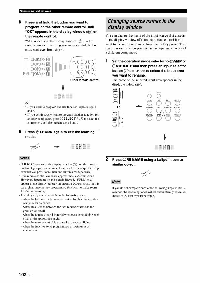
Remote control features
5 Press and hold the button you want to program on the other remote control until “OK” appears in the display window (A) on the remote control.“NG” appears in the display window (A) on the remote control if learning was unsuccessful. In this case, start over from step 4.
y• If you want to program another function, repeat steps 4
and 5.• If you continuously want to program another function for
another component, press ASELECT k / n to select the component, and then repeat steps 4 and 5.
6 Press LLEARN again to exit the learning mode.
• “ERROR” appears in the display window (A) on the remote control if you press a button not indicated in the respective step, or when you press more than one button simultaneously.
• This remote control can learn approximately 200 functions. However, depending on the signals learned, “FULL” may appear in the display before you program 200 functions. In this case, clear unnecessary programmed functions to make room for further learning.
• Learning may not be possible in the following cases:– when the batteries in the remote control for this unit or other
components are weak.– when the distance between the two remote controls is too
great or too small.– when the remote control infrared windows are not facing each
other at the appropriate angle.– when the remote control is exposed to direct sunlight.– when the function to be programmed is continuous or
uncommon.
You can change the name of the input source that appears in the display window (A) on the remote control if you want to use a different name from the factory preset. This feature is useful when you have set an input area to control a different component.
1 Set the operation mode selector to CAMP or CSOURCE and then press an input selector button (1), or to select the input area you want to rename.The name of the selected input area appears in the display window (A).
2 Press LRENAME using a ballpoint pen or similar object.
If you do not complete each of the following steps within 30 seconds, the renaming mode will be automatically canceled. In this case, start over from step 2.
Notes
AV
TV
SELECT
DT
V/C
BL
VC
RD
VR
V-AUX/DOCK
TU
NE
RC
DC
D-R
MULTI CH IN
PO
WE
RP
OW
ER
PO
WE
RSTANDBY
SL
EE
PA
UD
IO S
EL
DV
DB
D/H
D D
VD
PH
ON
OM
D/TA
PE
Other remote control
LEARN
Changing source names in the display window
Note
DTV/CBL VCRDVR V-AUX/DOCK
TUNER CD CD-R MULTI CH IN
DVD BD/HD DVD PHONOMD/TAPE
TV
SOURCE
AMP
TV
SOURCE
AMP
or
RENAME
102 En

Remote control featuresA
DVA
NC
ED
O
PE
RA
TIO
NE
ng
lish
3 Press 3k / n to select and enter a character.Pressing 3n changes the character as follows: A to Z, 1 to 9, 0, + (plus), – (hyphen), ; (semicolon), / (slash), and space. Pressing 3k changes the characters in reverse order.
4 Press 3h to move the cursor to the next position.
yPress 3l to move the cursor to the previous position.
5 Press 3ENTER to set the new name.“OK” appears in the display window (A) on the remote control if renaming was successful.“NG” appears in the display window (A) on the remote control if renaming was unsuccessful. In this case, start over from step 3.
yIf you continuously want to rename another input area, press the input selector button (1) or , or press ASELECT k / n repeatedly to select the component, then repeat steps 3 through 5.
6 Press LRENAME again to exit the renaming mode.
“ERROR” appears in the display window (A) on the remote control if you press a button not indicated in the respective step, or when you press more than one button simultaneously.
The macro programming feature makes it possible to perform a series of operations with the press of a single button. For example, when you want to play a CD, normally you would turn on the components, select the CD input, and press the play button to start playback. The macro programming feature lets you perform all of these operations simply by pressing the CD macro button. The buttons listed as macro buttons below are factory set with macro programs. You can also program your own macros (see page 105).
MACRO operations
1 Set the LMACRO ON/OFF selector to ON.
2 Press the desired macro button.
3 Set the LMACRO ON/OFF selector to OFF when you finish to using the macro programming operation.
• While the remote control is running a macro program, it does not accept any other operation until it has completed running the program (the transmission indicator stops flashing).
• Continue to aim the remote control at the component the macro is operating until the macro operation is complete.
Note
ENTER
A/B/C/D/E
PRESET/CH
ENTER
A/B/C/D/E
PRESET/CH
RENAME
Macro programming features
Notes
AVTV
ENT+1009
DTV/CBL VCRDVR V-AUX/DOCK
TUNER CD CD-R MULTI CH IN
POWER POWER POWERSTANDBY
SLEEPAUDIO SEL
DVD BD/HD DVD PHONOMD/TAPE
ONOFF CLEARLEARN RENAMEMACRO
REC
DISC SKIP
FREQ/TEXT EON MODE – PTY SEEK – START
MACROMACRO ON/OFF
Macro buttons
ONOFF CLEARLEARNMACRO
ONOFF CLEARLEARNMACRO
103 En

Remote control features
Default macro functions
*1 You can turn on some components (including Yamaha components) connected to this unit by connecting them to the AC OUTLET(S) on the rear panel of this unit. Power control may not be synchronized with this unit depending on the component. For details, refer to the operating instructions for the connected component.
*2 When the remote control code for your TV is set up for either DTV/CBL or PHONO (see page 99), you can turn on the power of your TV without selecting an input source. The remote control code set up for DTV takes priority over the one for PHONO.
*3 When TUNER is selected as the input source, this unit plays the last station received before the unit was set in the standby mode.*4 Playback can be started for any Yamaha remote control-compatible MD recorder, CD player, CD recorder, DVD player, Blu-ray
Disc player, HD DVD player or DVD recorder. When using macros to operate other components, you will need to program the play button on the input area of that component (see page 101) or set a remote control code (see page 99) in advance.
Pressing macro button
To automatically transmit these signals in orderFirst Second Third
— —
—
— —
—
(*1)
—
(CD area) (*4)
(CD-R area) (*4)
—
(MD/TAPE area) (*4)
(DVD area) (*4)
(BD/HD DVD area) (*4)
—
—
(DVR area) (*4)
(VCR area) (*4)
—
STANDBY STANDBY
POWER POWER (*1)TV
POWER (*2)
POWER
POWER
TUNER
POWER
TUNER (*3)
CD CD
CD-R CD-R
MULTI CH IN MULTI CH IN
MD/TAPE MD/TAPE
DVD DVD
BD/HD DVD BD/HD DVD
PHONO PHONO
DTV/CBL DTV/CBL
DVR DVR
VCR VCR
V-AUX/DOCK V-AUX/DOCK
104 En

Remote control featuresA
DVA
NC
ED
O
PE
RA
TIO
NE
ng
lish
Programming macro operationsYou can program your own macro and use the macro programming feature to transmit several remote control commands in sequence at the press of a button. Be sure to set up remote control codes or perform learning operations before programming the macro.
• The default macro is not cleared when a new macro is programmed for a button. The default macro can be used again when the programmed macro is cleared.
• It is not possible to add a new signal (macro step) to the default macro. Programming a macro changes all macro contents.
• We do not recommend programming continuous operations such as volume control in a macro.
1 Set the operation mode selector to CAMP or CSOURCE and then press LMACRO using a ballpoint pen or similar object.“MCR ?” appears in the display window (A) on the remote control.
If you do not complete each of the following steps within 30 seconds, the macro programming mode will be automatically canceled. In this case, start over from step 1.
2 Press the LMACRO button you want to use to operate the macro.The macro button name (e.g. “M;DVD”) and the selected component name (e.g. “DVD”) appear alternately in the display window (A) on the remote control.
“AGAIN” appears in the display window (A) if you press a button other than a macro button.
3 Press the buttons for the functions you want to include in the macro operation in sequence.You can set up to 10 steps (10 functions). After you have set 10 steps, “FULL” appears and the remote control automatically exits the macro mode.
Example:Set the input source to DVD → Activate the DVD player → Set the sleep timer
Step 1 (“MCR 1”): Press DVD.Step 2 (“MCR 2”): Press AV POWER.Step 3 (“MCR 3”): Press SLEEP.
To change the selected input area, press ASELECT k / n. Pressing the input selector buttons will program a macro step, whereas ASELECT k / n only changes the selected input area.
4 Press LMACRO again using a ballpoint pen or similar object when the operation sequence you want to program is complete.
“ERROR” appears in the display window (A) if you press more than one button simultaneously.
Notes
Note
MACRO
TV
SOURCE
AMP
TV
SOURCE
AMP
or
DTV/CBL VCRDVR V-AUX/DOCK
TUNER CD CD-R MULTI CH IN
DVD BD/HD DVD PHONOMD/TAPE
POWERSTANDBY
Note
Note
Note
AVTV
SELECT
DTV/CBL VCRDVR V-AUX/DOCK
TUNER CD CD-R MULTI CH IN
POWER POWER POWERSTANDBY
SLEEPAUDIO SEL
DVD BD/HD DVD PHONOMD/TAPE
1
2
3
Indicates the number of macro steps entered
Flashes alternately so you can set the next step
105 En

Remote control features
You can clear all changes made in each function set, such as learned functions, macros, renamed input area names and setup remote control codes.
Clearing function sets
1 Set the operation mode selector to CAMP or CSOURCE and then press LCLEAR by using a ballpoint pen or similar object.“CLEAR” appears in the display window (A).
If you do not complete each of the following steps within 30 seconds, the clearing mode will be automatically canceled. In this case, start over from step 1.
2 Press 3k / n to select the clear mode.
L;CD (etc.) (L; Name of an input area)Clears all learned functions in the respective input area. The name of a component is shown after a semicolon (;). Press an input selector button to select the input area.
L;AMP Clears all learned functions for controlling the amplifier functions of this unit.
L;ALL Clears all learned functions.M;ALL Clears all programmed macros.RNAME Clears all renamed source names.FCTRY Clears all remote functions and returns the
remote to the factory settings.
3 Press and hold LCLEAR again for about 3 seconds.“WAIT” appears in the display window (A). If clearing was successful, “C;OK” appears in the display window (A) on the remote control.
yOnce you have cleared a learned function for a button, the button reverts to the factory setting (or to the manufacturer setting if you have set remote control codes).
• “L;ALL” and “FCTRY” may take about 30 seconds to complete.
• “C;NG” appears in the display window (A) if clearing was unsuccessful. In this case start over from step 2.
• “ERROR” appears in the display window (A) if you press a button not indicated in the respective step, or if you press more than one button simultaneously.
4 Press LCLEAR again to exit.
Clearing a learned functionYou can clear the function learned for a certain button in each control area.
1 Set the operation mode selector to CAMP or CSOURCE and then press an input selector button (1), or to select the input area containing the function you want to clear.The selected component name appears in the display window.
Clearing configurations
Note
CLEAR
TV
SOURCE
AMP
TV
SOURCE
AMP
or Notes
CLEAR
DTV/CBL VCRDVR V-AUX/DOCK
TUNER CD CD-R MULTI CH IN
DVD BD/HD DVD PHONOMD/TAPE
TV
SOURCE
AMP
TV
SOURCE
AMP
or
106 En

Remote control featuresA
DVA
NC
ED
O
PE
RA
TIO
NE
ng
lish
2 Press LLEARN using a ballpoint pen or similar object.“LEARN” and the selected component name (e.g. “DVD”) appear alternately in the display window.
• Do not press and hold LLEARN. If you hold it down for more than 3 seconds, the remote control enters the remote control code setting mode.
• If you do not complete each of the following steps within 30 seconds, the learning mode will be automatically canceled. In this case, start over from step 2.
3 Press and hold LCLEAR using a ballpoint pen or similar object and then press the button you want to clear for about 3 seconds.“C;OK” appears in the display window (A) if clearing was successful. Once “C;OK” appears in the display window on the remote control, release the ballpoint pen or similar object used to press LCLEAR to exit the clearing mode. The remote control returns to the learning mode.
y• If you continuously want to clear another function, repeat
step 4.• If you continuously want to clear another function for
another component, press ASELECT k / n to select the input area, then repeat step 3.
• Once you clear a learned function, the button reverts to the factory setting (or to the manufacturer setting if you have set remote control codes).
4 Press LLEARN again to exit.
• “C;NG” appears in the display window (A) on the remote control if clearing was unsuccessful. In this case, start over from step 2.
• “ERROR” appears in the display window (A) if you press more than one button simultaneously.
Clearing a macro functionYou can clear the function programmed for a certain macro button.
1 Set the operation mode selector to CAMP or CSOURCE and then press LMACRO using a ballpoint pen or similar object.“MCR ?” appears in the display window (A) on the remote control.
If you do not complete each of the following steps within 30 seconds, the macro programming mode will be automatically canceled. In this case, start over from step 1.
2 Press and hold LCLEAR using a ballpoint pen or similar object, then press the macro button you want to clear for about 3 seconds.“C;OK” appears in the display window (A) on the remote control if clearing was successful.
y• If you continuously want to clear another function, repeat
step 2.• Once you clear a programmed function, the button reverts
to the factory setting (or to the manufacturer setting if you have set remote control codes).
3 Press LMACRO again to exit the macro programming mode.
• “C;NG” appears in the display window (A) on the remote control if clearing was unsuccessful. In this case, start over from step 2.
• “ERROR” appears in the display window (A) on the remote control if you press more than one button simultaneously.
Notes
Notes
LEARN
CLEARLEARN RENAME
MODE – PTY SEEK – START
Note
Notes
MACRO
TV
SOURCE
AMP
TV
SOURCE
AMP
or
ONOFF CLEARLEARN RENAMEMACRO
DTV/CBL VCRDVR V-AUX/DOCK
DVD BD/HD DVD PHONOMD/TAPE
107 En

This unit allows you to configure a multi-zone audio system. The multi-zone configuration feature enables you to set this unit to reproduce separate input sources in the main zone, second zone (Zone 2) and third zone (Zone 3). You can control this unit from the second or third zone using the supplied remote control.
You need the following additional equipment to use the multi-zone functions of this unit:• An infrared signal receiver in Zone 2 and/or Zone 3.• An infrared signal emitter in the main zone. This emitter transmits the infrared signals from the remote control in
Zone 2 and/or Zone 3 to the main zone (to a CD player or DVD player, for example).• An amplifier and speakers for Zone 2 and/or Zone 3.
y• You do not need an extra amplifier and speakers for Zone 2 and/or Zone 3 if you want to use the internal amplifiers of this unit.• Since there are many possible ways to connect and use this unit in a multi-zone configuration, we recommend that you consult with
your nearest authorized Yamaha dealer or service center for the Zone 2 and Zone 3 connections that best meet your requirements.
Using external amplifiersTo use an external amplifier in Zone 2 or Zone 3, connect the external amplifier to ZONE OUT jacks and select “EXT” in “AMP” (see page 91).
• To avoid unexpected noise, DO NOT use the Zone 2/Zone 3 feature with CDs encoded in DTS.• Adjust the Zone 2/Zone 3 volume by using the amplifier in the Zone 2/Zone 3 when “VOLUME” are set to “FIX” (see page 92).
Using multi-zone configuration
Connect the source component to the analog audio input jacks of this unit to play back the source in Zone 2 or Zone 3. This unit does not output the audio signals input at the DIGITAL INPUT and HDMI jacks to the ZONE OUT jacks.
Connecting the Zone 2 and Zone 3 components
Notes
OUTOUT IN
REMOTE
IN
REMOTE
OUT IN
REMOTE REMOTE
This unit Yamaha component
Yamaha component
Infrared signal receiver
MAIN
ZONE 2
ZONE 3
Infrared signal emitter
DVD player etc.
Amplifier
Remote control
Infrared signal receiver
Amplifier
Remote control
Infrared signal receiver
Second zone (Zone 2)
Third zone (Zone 3)Main zone
This unit
From the ZONE OUT (ZONE 2) jacks
From the ZONE OUT (ZONE 3) jacks
To the REMOTE IN jack
To the REMOTE IN jackFrom the REMOTE OUT jack
Analog audio signals only
108 En

Using multi-zone configurationA
DVA
NC
ED
O
PE
RA
TIO
NE
ng
lish
Using the internal amplifiers of this unit
If you want to use one internal amplifier (SP1 or SP2) of this unitConnect the Zone 2 or Zone 3 speakers directly to the SP1 or SP2 speaker terminals and select either “[SP1]” or “[SP2]” for “AMP” (see page 91).
If you want to use two internal amplifiers (SP1 and SP2) of this unitConnect the Zone 2 and Zone 3 speakers directly to the SP1 and SP2 speaker terminals and select “BOTH” for “AMP” (see page 91).
You can select the zone you want to control by using the control buttons on the front panel or on the remote control.
Selecting Zone 2 or Zone 3
Front panel operations
1 Press PZONE 2 ON/OFF or PZONE 3 ON/OFF on the front panel to individually turn on or off Zone 2 or Zone 3.
2 Press PZONE CONTROLS on the front panel repeatedly to select the zone you want to control.
Each time you press PZONE CONTROLS, the front panel display changes as shown below, and the indicator for the currently selected zone flashes for approximately 10 seconds. However, no indicator flashes when the main zone is selected.
ZONE2Controls the Zone 2 amplifier or tuner functions.
ZONE3Controls the Zone 3 amplifier or tuner functions.
Important safety notice
The SP1 or SP2 speaker terminals of this Receiver should not be connected to a Passive Loudspeaker Selector Box or more than one loudspeaker per channel.Connection to a Passive Loudspeaker Selector Box or multiple speakers per channel could create an abnormally low impedance load resulting in amplifier damage. See this owner’s manual for correct usage.Compliance with minimum speaker impedance information for all channels must be maintained at all times. This information is found on the back panel of your Receiver.
R L
+
–
SP2
SINGLE
R L+–+ –
BI-AMPSURROUND BACK/
PRESENCE/ZONE 2/ZONE 3ZONE 2/ZONE 3
R L
SP1
+–+ –
Third zone (Zone 3)
This unit
Second zone (Zone 2)
Controlling Zone 2 or Zone 3
ZONE2 ZONE3
No indicator flashes when the main zone is selected.
109 En

Using multi-zone configuration
y• You must complete this step within 10 seconds while the
selected zone flashes in the front panel display. Otherwise, the currently selected zone mode is automatically canceled. In this case, press PZONE CONTROLS again.
• The initial setting is ZONE2 when both Zone 2 and Zone 3 are turned on.
3 Refer to “Selecting the input source of Zone 2 or Zone 3”, “Adjusting the volume level of Zone 2 or Zone 3”, “Adjusting the balance of the speaker level in Zone 2 or Zone 3” or “Adjusting the tonal quality of Zone 2 or Zone 3” on page 111 to perform further operations.
Remote control operations
1 Set the operation mode selector to CAMP and then press ASELECT k repeatedly to select the zone you want to control.“ZONE 2” or “ZONE 3” is displayed in the display window (A) on the remote control.
2 Refer to “Selecting the input source of Zone 2 or Zone 3”, “Adjusting the volume level of Zone 2 or Zone 3”, “Adjusting the balance of the speaker level in Zone 2 or Zone 3” or “Adjusting the tonal quality of Zone 2 or Zone 3” on page 111 to perform further operations.
3 Press ASELECT k / n to exit from the Zone 2/Zone 3 mode.
Turning on or off Zone 2 and/or Zone 3 using the remote control
8POWER and 7STANDBY on the remote control work differently depending on the selected zone that appears in the display window (A) on the remote control.• When the main zone, Zone 2 or Zone 3 mode is
selected, you can turn on the main zone, Zone 2 or Zone 3 or set them to the standby mode individually.
• When the all mode is selected, pressing 8POWER turns on the main zone, Zone 2 and Zone 3 simultaneously and pressing 7STANDBY sets them to the standby mode simultaneously.
• When the remote control is in the main zone mode, “MAIN” appears for a few seconds when 8POWER or 7STANDBY is pressed.
• “ALL” appears in the display window (A) on the remote control only when ASELECT n is pressed.
SELECT
TV
SOURCE
AMP
or
Control modeDisplay window
(A)
POWER and
STANDBY
Main zone mode
Name of the selected input area
Turns on the main zone only or sets it to the standby mode.
Zone 2 mode“ZONE 2” or “2;name of the selected input area”
Turns on Zone 2 or sets it to the standby mode.
Zone 3 mode“ZONE 3” or “3;name of the selected input area”
Turns on Zone 3 or sets it to the standby mode.
All mode “ALL”
8POWER: turns on the main zone, Zone 2 and Zone 3.7STANDBY: sets the main zone, Zone 2 and Zone 3 to the standby mode.
Notes
110 En
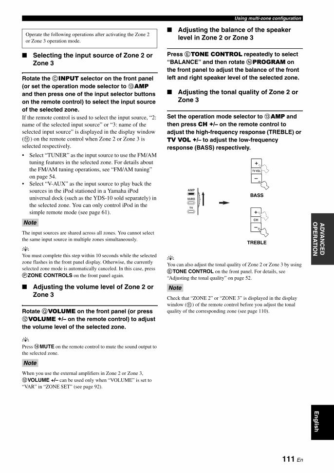
Using multi-zone configurationA
DVA
NC
ED
O
PE
RA
TIO
NE
ng
lish
Selecting the input source of Zone 2 or Zone 3
Rotate the CINPUT selector on the front panel (or set the operation mode selector to CAMP and then press one of the input selector buttons on the remote control) to select the input source of the selected zone.If the remote control is used to select the input source, “2: name of the selected input source” or “3: name of the selected input source” is displayed in the display window (A) on the remote control when Zone 2 or Zone 3 is selected respectively.
• Select “TUNER” as the input source to use the FM/AM tuning features in the selected zone. For details about the FM/AM tuning operations, see “FM/AM tuning” on page 54.
• Select “V-AUX” as the input source to play back the sources in the iPod stationed in a Yamaha iPod universal dock (such as the YDS-10 sold separately) in the selected zone. You can only control iPod in the simple remote mode (see page 61).
The input sources are shared across all zones. You cannot select the same input source in multiple zones simultaneously.
yYou must complete this step within 10 seconds while the selected zone flashes in the front panel display. Otherwise, the currently selected zone mode is automatically canceled. In this case, press PZONE CONTROLS on the front panel again.
Adjusting the volume level of Zone 2 or Zone 3
Rotate QVOLUME on the front panel (or press BVOLUME +/– on the remote control) to adjust the volume level of the selected zone.
yPress DMUTE on the remote control to mute the sound output to the selected zone.
When you use the external amplifiers in Zone 2 or Zone 3, BVOLUME +/– can be used only when “VOLUME” is set to “VAR” in “ZONE SET” (see page 92).
Adjusting the balance of the speaker level in Zone 2 or Zone 3
Press ETONE CONTROL repeatedly to select “BALANCE” and then rotate NPROGRAM on the front panel to adjust the balance of the front left and right speaker level of the selected zone.
Adjusting the tonal quality of Zone 2 or Zone 3
Set the operation mode selector to CAMP and then press CH +/– on the remote control to adjust the high-frequency response (TREBLE) or TV VOL +/– to adjust the low-frequency response (BASS) respectively.
yYou can also adjust the tonal quality of Zone 2 or Zone 3 by using ETONE CONTROL on the front panel. For details, see “Adjusting the tonal quality” on page 52.
Check that “ZONE 2” or “ZONE 3” is displayed in the display window (A) of the remote control before you adjust the tonal quality of the corresponding zone (see page 110).
Operate the following operations after activating the Zone 2 or Zone 3 operation mode.
Note
Note
Note
–
+TV VOL
+
–CH
TV
SOURCE
AMP
TREBLE
BASS
111 En
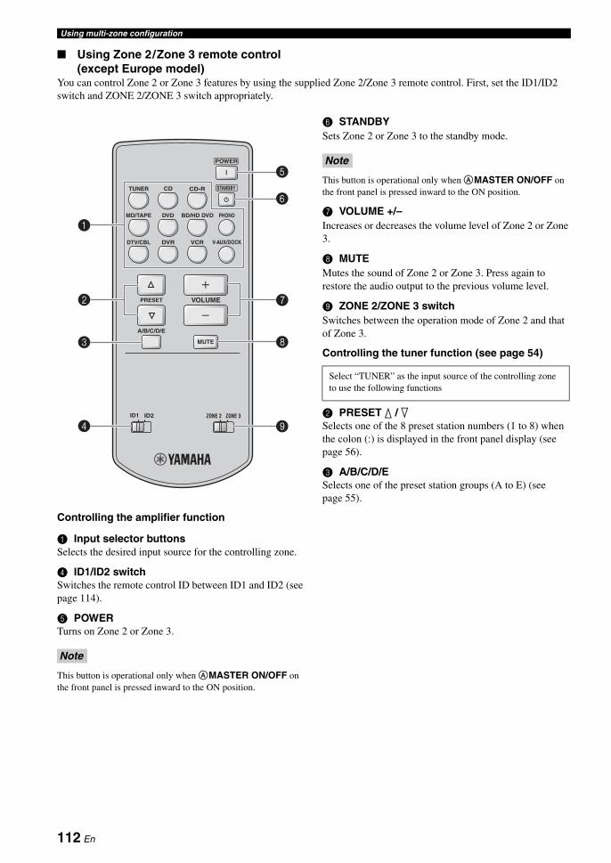
Using multi-zone configuration
Using Zone 2/Zone 3 remote control(except Europe model)
You can control Zone 2 or Zone 3 features by using the supplied Zone 2/Zone 3 remote control. First, set the ID1/ID2 switch and ZONE 2/ZONE 3 switch appropriately.
Controlling the amplifier function
1 Input selector buttonsSelects the desired input source for the controlling zone.
4 ID1/ID2 switchSwitches the remote control ID between ID1 and ID2 (see page 114).
5 POWERTurns on Zone 2 or Zone 3.
This button is operational only when AMASTER ON/OFF on the front panel is pressed inward to the ON position.
6 STANDBYSets Zone 2 or Zone 3 to the standby mode.
This button is operational only when AMASTER ON/OFF on the front panel is pressed inward to the ON position.
7 VOLUME +/–Increases or decreases the volume level of Zone 2 or Zone 3.
8 MUTEMutes the sound of Zone 2 or Zone 3. Press again to restore the audio output to the previous volume level.
9 ZONE 2/ZONE 3 switchSwitches between the operation mode of Zone 2 and that of Zone 3.
Controlling the tuner function (see page 54)
2 PRESET k / nSelects one of the 8 preset station numbers (1 to 8) when the colon (:) is displayed in the front panel display (see page 56).
3 A/B/C/D/ESelects one of the preset station groups (A to E) (see page 55).
Note
TUNER CD CD-R
MD/TAPE DVD BD/HD DVD PHONO
DTV/CBL VCR V-AUX/DOCKDVR
POWER
STANDBY
A/B/C/D/E
PRESET VOLUME
ZONE 3ZONE 2ID2ID1
MUTE
4 9
8
7
6
5
1
2
3
Note
Select “TUNER” as the input source of the controlling zone to use the following functions
112 En

AD
VAN
CE
D
OP
ER
AT
ION
En
glish
This unit has additional menus that are displayed in the front panel display. The advanced setup menu offers additional operations to adjust and customize the way this unit operates. Change the initial settings (indicated in bold under each parameter) to reflect the needs of your listening environment.
• The settings you make are reflected next time you press AMASTER ON/OFF inward to the ON position to turn on this unit (see page 33).
• Only AMASTER ON/OFF, OSTRAIGHT and the NPROGRAM selector are effective while you are using the advanced setup menu.
• All the other operations cannot be made while you are using the advanced setup menu.• The advanced setup menu is only available in the front panel display.
1 Press AMASTER ON/OFF on the front panel to release it outward to the OFF position to turn off this unit.
2 Press and hold OSTRAIGHT and then press AMASTER ON/OFF inward to the ON position to turn on this unit.This unit turns on, and “ADVANCED MENU” appears in the front panel display.
3 Rotate the NPROGRAM selector to select the parameter you want to adjust.The name of the selected parameter appears in the front panel display.
4 Press OSTRAIGHT repeatedly to change the selected parameter setting.
5 Press AMASTER ON/OFF to release it outward to the OFF position to save the new setting and turn off this unit.
yThe settings you made are reflected next time you turn on this unit.
Speaker impedance SPEAKER IMP.Use this feature to set the speaker impedance of this unit so that it matches that of your speakers.Choices: 8Ω MIN, 6Ω MIN• Select “8Ω MIN” to set the speaker impedance to 8 Ω .• Select “6Ω MIN” to set the speaker impedance to 6 Ω .
Remote sensor REMOTE SENSORUse this feature to activate or deactivate the signal-receiving capability of the remote control sensor on the front panel of this unit.Choices: ON, OFF• Select “ON” if you want to activate the signal-
receiving capability of the remote control sensor.• Select “OFF” if you want to deactivate the signal-
receiving capability of the remote control sensor.
We recommend that you set the parameter to “ON” in most cases.
Advanced setup
Notes
Using the advanced setup menu
EFFECT
STRAIGHT
MASTER
While holding down
SPEAKER IMP.
Speaker Impedance level
8Ω MIN
FrontThe impedance of each speaker must be 8 Ω or higher.
Center
The impedance of each speaker must be 8 Ω or higher.
Surround
Surround back
6Ω MIN
FrontThe impedance of each speaker must be 4 Ω or higher.
Center
The impedance of each speaker must be 6 Ω or higher.
Surround
Surround back
Note
113 En

Advanced setup
RS-232C access on the standby modeRS-232C STANDBY
Use this feature to set this unit to transmit data via the RS-232C interface when this unit is in the standby mode.Choices: YES, NOInitial setting:[U.S.A. and Canada models]: YES[Other models]: NO• Select “YES” to set this unit to transmit data via the
RS-232C interface.• Select “NO” to set this unit not to transmit data via the
RS-232C interface.
Remote control AMP IDRC AMP ID
Use this feature to set the AMP ID of this unit for remote control recognition.Choices: ID1, ID2• Select “ID1” when the remote control AMP ID library
code is set to “2001”.• Select “ID2” when the remote control AMP ID library
code is set to “2002”.
Setting remote control AMP ID code
1 Set the operation mode selector to CAMP or CSOURCE.
2 Press and hold LLEARN for about 3 seconds using a ballpoint pen or similar object and then press 3l / h repeatedly until “L;AMP” appears in the display window (A) on the remote control.
• Be sure to press and hold LLEARN for at least 3 seconds, otherwise the learning process will start.
• If you do not complete each of the following steps within 30 seconds, the setting mode will be automatically canceled. In this case, start over from step 2.
3 Press 3ENTER.The four-digit code set for the selected input area appears in the display window(A) on the remote control.
4 Press the numeric buttons (5) to enter the four-digit remote control AMP ID code for the input area you want to use.
*1 The remote control setting.*2 The setting of this unit.
5 Press 3ENTER to set the number.“OK” appears in the display window (A) if the setting was successful.“NG” appears in the display window (A) if the setting was unsuccessful. In this case, start over from step 2.
6 Press LLEARN again to exit from the setup mode.
Remote control TUNER IDRC TUNER ID
Use this feature to set the TUNER ID of this unit for remote control recognition.Choices: ID1, ID2• Select “ID1” when the remote control TUNER ID
library code is set to “2602”.• Select “ID2” when the remote control TUNER ID
library code is set to “2603”.
See page 113 for the operation of the advanced setup menu.
Notes
LEARN
ENTER
A/B/C/D/E
PRESET/CH
Remote control AMP
ID code*1Function RC AMP ID*2
2001(initial setting)
Operates this unit using the default code.
ID1 (initial setting)
2002Operates this unit using an alternative code.
ID2
ENTER
A/B/C/D/E
PRESET/CH
LEARN
114 En

Advanced setupA
DVA
NC
ED
O
PE
RA
TIO
NE
ng
lish
Setting remote control TUNER ID
1 Set the operation mode selector to CAMP or CSOURCE and then press 1TUNER on the remote control to select the tuner to change the remote control ID.
2 Press and hold LLEARN for about 3 seconds using a ballpoint pen or similar object until “L;TUN” and “TUNER” alternately appear in the display window (A).
• Be sure to press and hold LLEARN for at least 3 seconds, otherwise the learning process will start.
• If you do not complete each of the following steps within 30 seconds, the setting mode will be automatically canceled. In this case, start over from step 2.
3 Press 3ENTER.The four-digit code set for the selected input area appears in the display window (A) on the remote control.
4 Press the numeric buttons (5) to enter the four-digit remote control code for the input area you want to use.
*1 The remote control setting.*2 The setting of this unit.
5 Press 3ENTER to set the number.“OK” appears in the display window (A) if the setting was successful.“NG” appears in the display window (A) if the setting was unsuccessful. In this case, start over from step 2.
6 Press LLEARN again to exit from the setup mode.
Notes
LEARN
3 seconds
Remote control
TUNER ID code*1
FunctionRC TUNER
ID*2
2602 (initial setting)
Operates this unit using the default code.
ID1 (initial setting)
2603Operates this unit using an alternative code.
ID2
LEARN
115 En

Advanced setup
Tuner frequency step TUNER FRQ STEP(Asia and General models only)
Use this feature to set the tuner frequency step according to the frequency spacing in your area.Choices: AM10/FM100, AM9/FM50• Select “AM10/FM100” for North, Central and South
America.• Select “AM9/FM50” for all other areas.
Bi-amplifier setting BI-AMPUse this feature to activate or deactivate the bi-amplifier function (see page 19).Choices: ON, OFF• Select “ON” if you want to activate the bi-amplifier
function.• Select “OFF” if you want to deactivate the bi-amplifier
function.
When “BI-AMP” is set to “ON”, the SURROUND BACK terminals cannot be used to connect surround back speakers in that the SURROUND BACK terminals are already used for the bi-amplifier connection (see page 19).
Parameter initialization INITIALIZEUse this feature to reset the parameters of this unit to the initial factory settings. You can select the category of parameters to be initialized.Choices: DSP PARAM, VIDEO, ALL, CANCEL• Select “DSP PARAM” to initialize all the parameters
of the sound field parameters (see page 64).• Select “VIDEO” to initialize the parameters in
“VIDEO SET” (see page 89) and “OSD SHIFT” (see page 88) and “GRAY BACK” in “DISPLAY SET” (see page 88).
• Select “ALL” to initialize all the parameters of this unit.
• Select “CANCEL” to cancel the initialization procedure.
• The advanced setup menu parameters are not initialized.• Use “INITIALIZE” in the sound field program menu to
initialize the parameters of the desired program (see page 64).
HDMI video monitor checkMONITOR CHECK
Use this feature to activate or deactivate the monitor check function of this unit. When “MONITOR CHECK” is set to “YES”, this unit receives the information of the available video signal resolutions from the video monitor connected via HDMI and you can only select the resolutions supported by the video monitor in “HDMI SCALING” (see page 89). When “MONITOR CHECK” is set to “SKIP”, you can select nay resolution in “HDMI SCALING”.Choices: YES, SKIP
See page 113 for the operation of the advanced setup menu.
Note
Notes
116 En

TROUBLESHOOTINGA
DD
ITIO
NA
L
INF
OR
MA
TIO
NE
ng
lish
Refer to the table below when this unit does not function properly. If the problem you are experiencing is not listed below or if the instruction below does not help, turn off this unit, disconnect the power cable, and contact the nearest authorized Yamaha dealer or service center.
General
Troubleshooting
Problem Cause RemedySee
page
This unit fails to turn on or enters the standby mode soon after the power is turned on.
The power cable is not connected or the plug is not completely inserted.
Connect the power cable firmly. —
The speaker impedance setting is incorrect.
Set the speaker impedance to match your speakers. 33
The protection circuitry has been activated.
Make sure that all speaker wire connections on this unit and on all speakers are secure and that the wire for each connection does not touch anything other than its respective connection.
16
This unit has been exposed to a strong external electric shock (such as lightning or strong static electricity).
Turn off this unit, disconnect the power cable, plug it back in after 30 seconds and then use it normally.
—
No sound. Incorrect input or output cable connections.
Connect the cables properly. If the problem persists, the cables may be defective.
24-31
Audio input jack select is set to “HDMI”, “COAX/OPT” or “ANALOG”.
Set the audio input jack select to “AUTO”. 43
Audio input jack select is set to “ANALOG” while the input source component outputs digital audio signals.
Set the audio input jack select to “AUTO” or “COAX/OPT”.
43
No appropriate input source has been selected.
Select an appropriate input source with the CINPUT selector on the front panel (or the input selector buttons (1) on the remote control).
42, 43
Speaker connections are not secure. Secure the connections. 16
The volume is turned down. Turn up the volume. —
The sound is muted. Press DMUTE or BVOLUME +/– on the remote control to resume audio output and then adjust the volume.
44
Signals this unit cannot reproduce are being input from a source component, such as a CD-ROM.
Play a source whose signals can be reproduced by this unit.
—
The HDMI components connected to this unit do not support the HDCP copy protection standards.
Connect HDMI components that support the HDCP copy protection standards.
21
“SUPPORT AUDIO” is set to “OTHER” and “HDMI” audio signals are not being played back on this unit.
Set “SUPPORT AUDIO” to “RX-V1800” in “SET MENU”.
85
No picture. The output and input for the picture are connected to different types of video jacks.
Set “VIDEO CONV.” to “ON” or connect your source components in the same way as you connect your video monitor to this unit.
89
This unit outputs the video signals are not supported on the video monitor connected to the HDMI OUT jack.
Set the “INITIALIZE” to “VIDEO” to reset the video parameters.
116
Set “MON.CHK” to “YES”. 116
Pure Direct mode is active. Turn off the Pure Direct mode. 52
Non-standard video signals are input.
117 En

Troubleshooting
Short message displays do not appear on the video monitor.
“SHORT MESSAGE” is set to “OFF”. Set “SHORT MESSAGE” to “ON”. 88
“GRAY BACK” is set to “OFF”. Set “GRAY BACK” to “AUTO”. 88
“VIDEO CONV.” is set to “OFF”. Set “VIDEO CONV.” to “ON”. 89
The signals input at the HDMI input jacks are being output at the HDMI OUT jack.
Video signals in the progressive format or HDTV video signals are being input.
The sound suddenly goes off.
The protection circuitry has been activated because of a short circuit, etc.
Check that the speaker impedance setting is correct. 33, 113
Check that the speaker wires are not touching each other and then turn this unit back on.
—
The sleep timer has turned off this unit. Turn on this unit, and play the source again. —
The sound is muted. Press DMUTE or BVOLUME +/– on the remote control to resume audio output.
44
Sound is heard from the speaker on one side only.
Incorrect cable connections. Connect the cables properly. If the problem persists, the cables may be defective.
16
Incorrect settings in “SPEAKER LEVEL”.
Adjust the “SPEAKER LEVEL” settings. 79
Only the center speaker outputs substantial sound.
When playing a monaural source with a CINEMA DSP program, the source signal is directed to the center channel, and the front and surround speakers output effect sounds.
No sound is heard from the center speaker.
“CENTER SP” in “SET MENU” is set to “NONE”.
Set “CENTER SP” to “SMALL” or “LARGE”. 77
One of the HiFi DSP programs (except for “7ch Stereo”) has been selected.
Try another sound field program. 46
No sound is heard from the presence speakers.
The sound field programs are turned off. Press OSTRAIGHT to turn them on. 51
You are using a source or program combination that does not output sound from all channels.
Try another sound field program. 42
No sound is heard from the surround speakers.
“SUR. L/R SP” in “SET MENU” is set to “NONE”.
Set “SUR. L/R SP” to “SMALL” or “LARGE”. 78
This unit is in the “STRAIGHT” mode and a monaural source is being played back.
Press OSTRAIGHT on the front panel so that “STRAIGHT” disappears from the front panel display.
51
Speakers are connected to the SURROUND BACK speaker terminals.
Connect the surround speakers to the SURROUND speaker terminals.
51
No sound is heard from the subwoofer.
“LFE/BASS OUT” in “SET MENU” is set to “FRONT” when a Dolby Digital or DTS signal is being played.
Set “LFE/BASS OUT” to “SWFR” or “BOTH”. 77
“LFE/BASS OUT” in “SET MENU” is set to “SWFR” or “FRONT” when a 2-channel source is being played.
Set “LFE/BASS OUT” to “BOTH”. 77
The source does not contain low-frequency signals.
No sound is heard from the surround back speakers.
“SUR. L/R SP” in “SET MENU” is set to “NONE” and “SUR.B L/R SP” is automatically set to “NONE”.
Set “SUR. L/R SP” and “SUR.B L/R SP” to a setting other than “NONE”.
78
“SUR.B L/R SP” in “SET MENU” is set to “NONE”.
Set “SUR.B L/R SP” to a setting other than “NONE”. 78
Problem Cause RemedySee
page
118 En
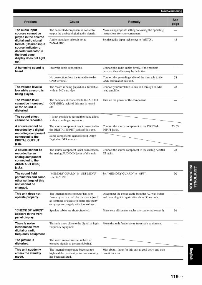
TroubleshootingA
DD
ITIO
NA
L
INF
OR
MA
TIO
NE
ng
lish
The audio input sources cannot be played in the desired digital audio signal format. (Desired input source indicator or decoder indicator in the front panel display does not light up.)
The connected component is not set to output the desired digital audio signals.
Make an appropriate setting following the operating instructions for your component.
—
Audio input jack select is set to “ANALOG”.
Set the audio input jack select to “AUTO”. 43
A humming sound is heard.
Incorrect cable connections. Connect the audio cables firmly. If the problem persists, the cables may be defective.
—
No connection from the turntable to the GND terminal.
Connect the grounding cable of the turntable to the GND terminal of this unit.
28
The volume level is low while a record is being played.
The record is being played on a turntable with an MC cartridge.
Connect your turntable to this unit through an MC-head amplifier.
28
The volume level cannot be increased, or the sound is distorted.
The component connected to the AUDIO OUT (REC) jacks of this unit is turned off.
Turn on the power of the component. —
The sound effect cannot be recorded.
It is not possible to record the sound effect with a recording component.
A source cannot be recorded by a digital recording component connected to the DIGITAL OUTPUT jack.
The source component is not connected to the DIGITAL INPUT jacks of this unit.
Connect the source component to the DIGITAL INPUT jacks.
25, 28
Some components cannot record Dolby Digital or DTS sources.
A source cannot be recorded by an analog component connected to the AUDIO OUT (REC) jacks.
The source component is not connected to the analog AUDIO IN jacks of this unit.
Connect the source component to the analog AUDIO IN jacks.
28
The sound field parameters and some other settings of this unit cannot be changed.
“MEMORY GUARD” in “SET MENU” is set to “ON”.
Set “MEMORY GUARD” to “OFF”. 90
This unit does not operate properly.
The internal microcomputer has been frozen by an external electric shock (such as lightning or excessive static electricity) or by a power supply with low voltage.
Disconnect the power cable from the AC wall outlet and then plug it in again after about 30 seconds.
—
“CHECK SP WIRES” appears in the front panel display.
Speaker cables are short-circuited. Make sure all speaker cables are connected correctly. 16
There is noise interference from digital or radio frequency equipment.
This unit is too close to the digital or high-frequency equipment.
Move this unit further away from such equipment. —
The picture is disturbed.
The video source uses scrambled or encoded signals to prevent dubbing.
This unit suddenly enters the standby mode.
The internal temperature becomes too high and the overheat protection circuitry has been activated.
Wait about 1 hour for this unit to cool down and then turn it back on.
—
Problem Cause RemedySee
page
119 En
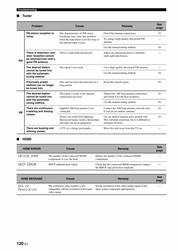
Troubleshooting
Tuner
HDMI
Problem Cause RemedySee
page
FM
FM stereo reception is noisy.
The characteristics of FM stereo broadcasts may cause this problem when the transmitter is too far away or the antenna input is poor.
Check the antenna connections. 32
Try using a high-quality directional FM antenna.
—
Use the manual tuning method. 54
There is distortion, and clear reception cannot be obtained even with a good FM antenna.
There is multi-path interference. Adjust the antenna position to eliminate multi-path interference.
—
The desired station cannot be tuned into with the automatic tuning method.
The signal is too weak. Use a high-quality directional FM antenna. —
Use the manual tuning method. 54
Previously preset stations can no longer be tuned into.
This unit has been disconnected for a long period.
Preset the stations again. 55
AM
The desired station cannot be tuned into with the automatic tuning method.
The signal is weak or the antenna connections are loose.
Tighten the AM loop antenna connections and orient it for the best reception.
32
Use the manual tuning method. 54
There are continuous crackling and hissing noises.
Supplied AM loop antenna is not connected.
Connect the AM loop antenna correctly even if you use an outdoor antenna.
32
Noises can result from lightning, fluorescent lamps, motors, thermostats and other electrical equipment.
Use an outdoor antenna and a ground wire. This will help somewhat, but it is difficult to eliminate all noise.
32
There are buzzing and whining noises.
A TV set is being used nearby. Move this unit away from the TV set. —
HDMI ERROR Cause RemedySee
page
DEVICE OVER The number of the connected HDMI components is over the limit.
Reduce the number of the connected HDMI components.
—
HDCP ERROR HDCP authentication failed. Check that the connected HDMI components support the HDCP copy protection standards.
—
HDMI MESSAGE Cause RemedySee
page
Out of Resolution
The connected video monitor is not compatible with the resolution of the input video signal.
Set the resolution of the video output signal of the input source component appropriately.
—
120 En

TroubleshootingA
DD
ITIO
NA
L
INF
OR
MA
TIO
NE
ng
lish
Remote control
Problem Cause RemedySee
page
The remote control does not work or function properly.
Wrong distance or angle. The remote control will function within a maximum range of 6 m (20 ft) and no more than 30 degrees off-axis from the front panel.
36
Direct sunlight or lighting (from an inverter type of fluorescent lamp, etc.) is striking the remote control sensor of this unit.
Reposition this unit. —
The batteries are weak. Replace all batteries. 5
The operation mode selector is set incorrectly.
Set the operation mode selector correctly. When operating this unit, set it to the CAMP position. When operating the component selected by the input selector button, set it to the CSOURCE position. When operating the TV set in the DTV or PHONO area, set it to the CTV position.
—
The remote control code is not correctly set.
Set the remote control code correctly using “List of remote control codes” at the end of this manual.
99
Try setting another code of the same manufacturer using “List of remote control codes” at the end of this manual.
99
The library code of the remote control and the remote control ID of this unit do not match.
Match the remote control ID of this unit with the corresponding remote control library code.
100, 114
Even if the remote control code is correctly set, there are some models that do not respond to the remote control.
Program the necessary functions independently into the programmable buttons using the Learn feature.
101
The remote control does not learn new functions.
The batteries of this remote control and/or the other remote control are too weak.
Replace the batteries. 5
The distance between the two remote controls is too much or too little.
Place the remote controls at the proper distance. 101
The signal coding or modulation of the other remote control is not compatible with this remote control.
Learning is not possible. —
Memory capacity is full. Delete other unnecessary functions to make room for the new functions.
106
121 En

Troubleshooting
iPod
In case of a transmission error without a status message appearing in the front panel and in the OSD, check the connection of your iPod (see page 31).
AUTO SETUP
Before AUTO SETUP
Note
Status message Cause RemedySee
page
Loading... This unit is in the middle of recognizing the connection with your iPod.
This unit is in the middle of acquiring song lists from your iPod.
Connect error There is a problem with the signal path from your iPod to this unit.
Turn off this unit and reconnect the Yamaha iPod universal dock to the DOCK terminal of this unit.
31
Try resetting your iPod. —
Unknown type The iPod being used is not supported by this unit.
Only iPod (Click and Wheel), iPod nano, and iPod mini are supported.
—
iPod connected Your iPod is properly stationed in a Yamaha iPod universal dock (such as the YDS-10, sold separately) connected to the DOCK terminal of this unit, and the connection between your iPod and this unit is complete.
Disconnected Your iPod was removed from a Yamaha iPod universal dock (such as YDS-10 sold separately) connected to the DOCK terminal of this unit.
Station your iPod back in a Yamaha iPod universal dock (such as YDS-10 sold separately) connected to the DOCK terminal of this unit.
31
Unable to play This unit cannot play back the songs currently stored on your iPod.
Check that the songs currently stored on your iPod are playable.
—
Store some other playable music files on your iPod. —
Error message Cause RemedySee
page
Connect MIC! Optimizer microphone is not connected. Connect the supplied optimizer microphone to the OPTIMIZER MIC jack on the front panel.
37
Unplug HP! Headphones are connected. Unplug the headphones. —
122 En
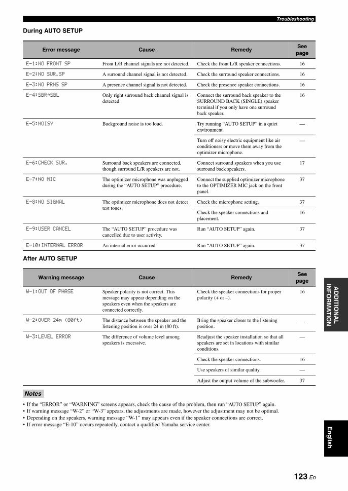
TroubleshootingA
DD
ITIO
NA
L
INF
OR
MA
TIO
NE
ng
lish
During AUTO SETUP
After AUTO SETUP
• If the “ERROR” or “WARNING” screens appears, check the cause of the problem, then run “AUTO SETUP” again.• If warning message “W-2” or “W-3” appears, the adjustments are made, however the adjustment may not be optimal.• Depending on the speakers, warning message “W-1” may appears even if the speaker connections are correct.• If error message “E-10” occurs repeatedly, contact a qualified Yamaha service center.
Error message Cause RemedySee
page
E-1:NO FRONT SP Front L/R channel signals are not detected. Check the front L/R speaker connections. 16
E-2:NO SUR.SP A surround channel signal is not detected. Check the surround speaker connections. 16
E-3:NO PRNS SP A presence channel signal is not detected. Check the presence speaker connections. 16
E-4:SBR.SBL Only right surround back channel signal is detected.
Connect the surround back speaker to the SURROUND BACK (SINGLE) speaker terminal if you only have one surround back speaker.
16
E-5:NOISY Background noise is too loud. Try running “AUTO SETUP” in a quiet environment.
—
Turn off noisy electric equipment like air conditioners or move them away from the optimizer microphone.
—
E-6:CHECK SUR. Surround back speakers are connected, though surround L/R speakers are not.
Connect surround speakers when you use surround back speakers.
17
E-7:NO MIC The optimizer microphone was unplugged during the “AUTO SETUP” procedure.
Connect the supplied optimizer microphone to the OPTIMIZER MIC jack on the front panel.
37
E-8:NO SIGNAL The optimizer microphone does not detect test tones.
Check the microphone setting. 37
Check the speaker connections and placement.
16
E-9:USER CANCEL The “AUTO SETUP” procedure was cancelled due to user activity.
Run “AUTO SETUP” again. 37
E-10:INTERNAL ERROR An internal error occurred. Run “AUTO SETUP” again. 37
Warning message Cause RemedySee
page
W-1:OUT OF PHASE Speaker polarity is not correct. This message may appear depending on the speakers even when the speakers are connected correctly.
Check the speaker connections for proper polarity (+ or –).
16
W-2:OVER 24m (80ft) The distance between the speaker and the listening position is over 24 m (80 ft).
Bring the speaker closer to the listening position.
—
W-3:LEVEL ERROR The difference of volume level among speakers is excessive.
Readjust the speaker installation so that all speakers are set in locations with similar conditions.
—
Check the speaker connections. 16
Use speakers of similar quality. —
Adjust the output volume of the subwoofer. 37
Notes
123 En
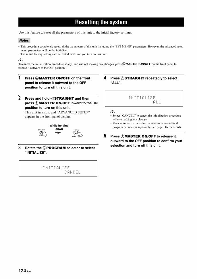
RESETTING THE SYSTEM
Use this feature to reset all the parameters of this unit to the initial factory settings.
• This procedure completely resets all the parameters of this unit including the “SET MENU” parameters. However, the advanced setup menu parameters will not be initialized.
• The initial factory settings are activated next time you turn on this unit.
yTo cancel the initialization procedure at any time without making any changes, press AMASTER ON/OFF on the front panel to release it outward to the OFF position.
1 Press AMASTER ON/OFF on the front panel to release it outward to the OFF position to turn off this unit.
2 Press and hold OSTRAIGHT and then press AMASTER ON/OFF inward to the ON position to turn on this unit.This unit turns on, and “ADVANCED SETUP” appears in the front panel display.
3 Rotate the NPROGRAM selector to select “INITIALIZE”.
4 Press OSTRAIGHT repeatedly to select “ALL”.
y• Select “CANCEL” to cancel the initialization procedure
without making any changes.• You can initialize the video parameters or sound field
program parameters separately. See page 116 for details.
5 Press AMASTER ON/OFF to release it outward to the OFF position to confirm your selection and turn off this unit.
Resetting the system
Notes
EFFECT
STRAIGHT
MASTER
While holding down
I N I T I A L I Z E
C A N C E L
I N I T I A L I Z E
A L L
124 En

GLOSSARYA
DD
ITIO
NA
L
INF
OR
MA
TIO
NE
ng
lish
Audio and video synchronization (lip sync)
Lip sync, an abbreviation for lip synchronization, is a technical term that involves both a problem and a capability of maintaining audio and video signals synchronized during post-production and transmission. Whereas the audio and video latency requires complex end-user adjustments, HDMI version 1.3 incorporates an automatic audio and video syncing capability that allows devices to perform this synchronization automatically and accurately without user interaction.
Bi-amplification connectionA bi-amplification connection uses two amplifiers for a speaker. One amplifier is connected to the woofer section of a loudspeaker while the other is connected to the combined mid and tweeter section. With this arrangement each amplifier operates over a restricted frequency range. This restricted range presents each amplifier with a much simpler job and each amplifier is less likely to influence the sound in some way. The internal crossover of the speaker consists of a LPF (low pass filter) and a HPF (high pass filter). As its name implies, the LPF passes frequencies below a cutoff and rejects frequencies above the cutoff frequency. Likewise, the HPF passes frequencies above its cutoff.
Component video signalWith the component video signal system, the video signal is separated into the Y signal for the luminance and the PB and PR signals for the chrominance. Color can be reproduced more faithfully with this system because each of these signals is independent. The component signal is also called the “color difference signal” because the luminance signal is subtracted from the color signal. A monitor with component input jacks is required in order to output component signals.
Composite video signalWith the composite video signal system, the video signal is composed of three basic elements of a video picture: color, brightness and synchronization data. A composite video jack on a video component transmits these three elements combined.
Deep ColorDeep Color refers to the use of various color depths in displays, up from the 24-bit depths in previous versions of the HDMI specification. This extra bit depth allows HDTVs and other displays go from millions of colors to billions of colors and eliminate on-screen color banding for smooth tonal transitions and subtle gradations between colors. The increased contrast ratio can represent many times more shades of gray between black and white. Also Deep Color increases the number of available colors within the boundaries defined by the RGB or YCbCr color space.
Dialogue normalizationDialogue Normalization is a feature of Dolby Digital or DTS, which is used to keep the programs at the same average listening level so that the user does not have to change the volume control between Dolby Digital or DTS programs.
Dolby DigitalDolby Digital is a digital surround sound system that gives you completely independent multi-channel audio. With 3 front channels (front L/R and center), and 2 surround stereo channels, Dolby Digital provides 5 full-range audio channels. With an additional channel especially for bass effects, called LFE (Low Frequency Effect), the system has a total of 5.1-channels (LFE is counted as 0.1 channel). By using 2-channel stereo for the surround speakers, more accurate moving sound effects and surround sound environment are possible than with Dolby Surround. The wide dynamic range from maximum to minimum volume reproduced by the 5 full-range channels and the precise sound orientation generated using digital sound processing provide listeners with unprecedented excitement and realism. With this unit, any sound environment from monaural up to a 5.1-channel configuration can be freely selected for your enjoyment.
Dolby Digital EXDolby Digital EX creates 6 full-bandwidth output channels from 5.1-channel sources. This is done using a matrix decoder that derives 3 surround channels from the 2 in the original recording. For the best results, Dolby Digital EX should be used with movie sound tracks recorded with Dolby Digital Surround EX. With this additional channel, you can experience more dynamic and realistic moving sound especially with scenes with “fly-over” and “fly-around” effects.
Glossary
125 En
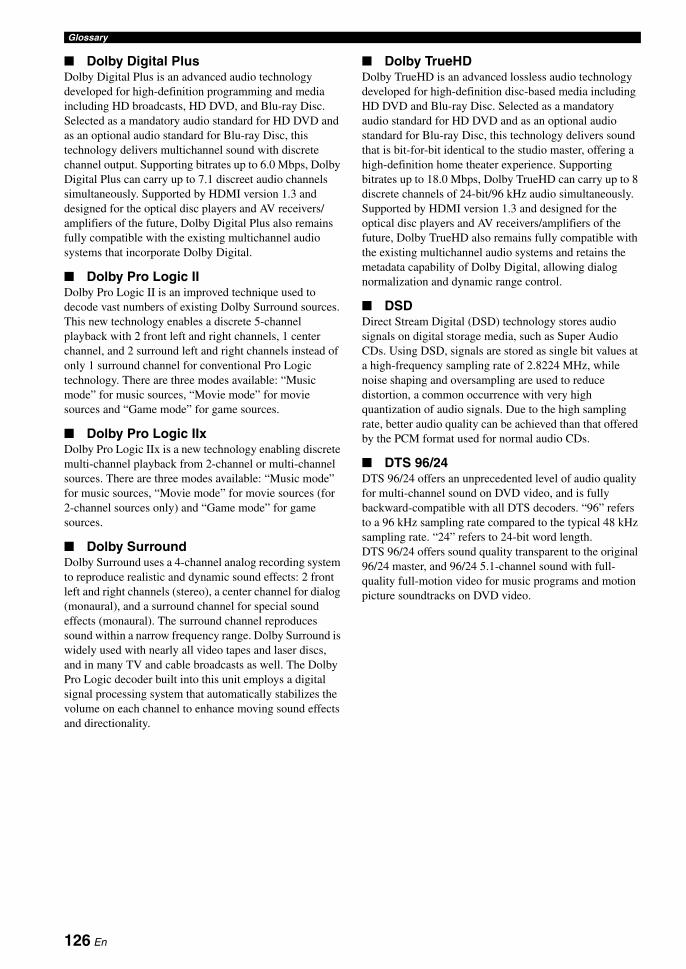
Glossary
Dolby Digital PlusDolby Digital Plus is an advanced audio technology developed for high-definition programming and media including HD broadcasts, HD DVD, and Blu-ray Disc. Selected as a mandatory audio standard for HD DVD and as an optional audio standard for Blu-ray Disc, this technology delivers multichannel sound with discrete channel output. Supporting bitrates up to 6.0 Mbps, Dolby Digital Plus can carry up to 7.1 discreet audio channels simultaneously. Supported by HDMI version 1.3 and designed for the optical disc players and AV receivers/amplifiers of the future, Dolby Digital Plus also remains fully compatible with the existing multichannel audio systems that incorporate Dolby Digital.
Dolby Pro Logic IIDolby Pro Logic II is an improved technique used to decode vast numbers of existing Dolby Surround sources. This new technology enables a discrete 5-channel playback with 2 front left and right channels, 1 center channel, and 2 surround left and right channels instead of only 1 surround channel for conventional Pro Logic technology. There are three modes available: “Music mode” for music sources, “Movie mode” for movie sources and “Game mode” for game sources.
Dolby Pro Logic IIxDolby Pro Logic IIx is a new technology enabling discrete multi-channel playback from 2-channel or multi-channel sources. There are three modes available: “Music mode” for music sources, “Movie mode” for movie sources (for 2-channel sources only) and “Game mode” for game sources.
Dolby SurroundDolby Surround uses a 4-channel analog recording system to reproduce realistic and dynamic sound effects: 2 front left and right channels (stereo), a center channel for dialog (monaural), and a surround channel for special sound effects (monaural). The surround channel reproduces sound within a narrow frequency range. Dolby Surround is widely used with nearly all video tapes and laser discs, and in many TV and cable broadcasts as well. The Dolby Pro Logic decoder built into this unit employs a digital signal processing system that automatically stabilizes the volume on each channel to enhance moving sound effects and directionality.
Dolby TrueHDDolby TrueHD is an advanced lossless audio technology developed for high-definition disc-based media including HD DVD and Blu-ray Disc. Selected as a mandatory audio standard for HD DVD and as an optional audio standard for Blu-ray Disc, this technology delivers sound that is bit-for-bit identical to the studio master, offering a high-definition home theater experience. Supporting bitrates up to 18.0 Mbps, Dolby TrueHD can carry up to 8 discrete channels of 24-bit/96 kHz audio simultaneously. Supported by HDMI version 1.3 and designed for the optical disc players and AV receivers/amplifiers of the future, Dolby TrueHD also remains fully compatible with the existing multichannel audio systems and retains the metadata capability of Dolby Digital, allowing dialog normalization and dynamic range control.
DSDDirect Stream Digital (DSD) technology stores audio signals on digital storage media, such as Super Audio CDs. Using DSD, signals are stored as single bit values at a high-frequency sampling rate of 2.8224 MHz, while noise shaping and oversampling are used to reduce distortion, a common occurrence with very high quantization of audio signals. Due to the high sampling rate, better audio quality can be achieved than that offered by the PCM format used for normal audio CDs.
DTS 96/24DTS 96/24 offers an unprecedented level of audio quality for multi-channel sound on DVD video, and is fully backward-compatible with all DTS decoders. “96” refers to a 96 kHz sampling rate compared to the typical 48 kHz sampling rate. “24” refers to 24-bit word length. DTS 96/24 offers sound quality transparent to the original 96/24 master, and 96/24 5.1-channel sound with full-quality full-motion video for music programs and motion picture soundtracks on DVD video.
126 En

GlossaryA
DD
ITIO
NA
L
INF
OR
MA
TIO
NE
ng
lish
DTS Digital SurroundDTS digital surround was developed to replace the analog soundtracks of movies with a 6.1-channel digital sound track, and is now rapidly gaining popularity in movie theaters around the world. DTS, Inc. has developed a home theater system so that you can enjoy the depth of sound and natural spatial representation of DTS digital surround in your home. This system produces practically distortion-free 6-channel sound (technically, front left and right, center, surround left and right, and LFE 0.1 (subwoofer) channels for a total of 5.1 channels). This unit incorporates a DTS-ES decoder that enables 6.1-channel reproduction by adding the surround back channel to the existing 5.1-channel format.
DTS ExpressDTS Express is an advanced audio technology for the optional feature on Blu-ray Disc or HD DVD, which offers high-quality, low bit rate audio optimized for network streaming, and Internet applications. DTS Express is used for the Secondary Audio feature of Blu-ray Disc or the Sub Audio feature of HD DVD. These features deliver audio commentaries (for example, the additional commentaries made by the director of a film) on demand by the users via the Internet, etc. DTS Express signals are mixed down with the main audio stream on the player component, and the component sends the mixed audio stream to the AV receivers/amplifiers via digital coaxial, digital optical, or analog connections.
DTS-HD High Resolution AudioDTS-HD High Resolution Audio is an high resolution audio technology developed for high-definition disc-based media including HD DVD and Blu-ray Disc. Selected as an optional audio standard for both HD DVD and Blu-ray Disc, this technology delivers sound that is virtually indistinguishable from the original, offering a high-definition home theater experience. Supporting bitrates up to 3.0 Mbps for HD DVD and 6.0 Mbps for Blu-ray Disc, DTS-HD High Resolution Audio can carry up to 7.1 discrete channels of 24-bit/96 kHz audio simultaneously. Supported by HDMI version 1.3 and designed for the optical disc players and AV receivers/amplifiers of the future, DTS-HD High Resolution Audio also remains fully compatible with the existing multichannel audio systems that incorporate DTS Digital Surround.
DTS-HD Master AudioDTS-HD Master Audio is an advanced lossless audio technology developed for high-definition disc-based media including HD DVD and Blu-ray Disc. Selected as a mandatory audio standard for both HD DVD and Blu-ray Disc, this technology delivers sound that is bit-for-bit identical to the studio master, offering a high-definition home theater experience. Supporting bitrates up to 18.0 Mbps for HD DVD and up to 24.5 Mbps for Blu-ray Disc, DTS-HD Master Audio can carry up to 7.1 discrete channels of 24-bit/96 kHz audio simultaneously. Supported by HDMI version 1.3 and designed for the optical disc players and AV receivers of the future, DTS-HD Master Audio also remains fully compatible with the existing multichannel audio systems that incorporate DTS Digital Surround.
HDMIHDMI (High-Definition Multimedia Interface) is the first industry-supported, uncompressed, all-digital audio/video interface. Providing an interface between any source (such as a set-top box or AV receiver) and an audio/video monitor (such as a digital television), HDMI supports standard, enhanced or high-definition video as well as multi-channel digital audio using a single cable. HDMI transmits all ATSC HDTV standards and supports 8-channel digital audio, with bandwidth to spare to accommodate future enhancements and requirements.When used in combination with HDCP (High-bandwidth Digital Content Protection), HDMI provides a secure audio/video interface that meets the security requirements of content providers and system operators. For further information on HDMI, visit the HDMI website at “http://www.hdmi.org/”.
LFE 0.1 channelThis channel reproduces low-frequency signals. The frequency range of this channel is from 20 Hz to 120 Hz. This channel is counted as 0.1 because it only enforces a low-frequency range compared to the full-range reproduced by the other 5/6 channels in Dolby Digital or DTS 5.1/6.1-channel systems.
Neo:6Neo:6 decodes the conventional 2-channel sources for 6- channel playback by the specific decoder. It enables playback with the full-range channels with higher separation just like digital discrete signal playback. There are two modes available: “Music mode” for music sources and “Cinema mode” for movie sources.
127 En

Glossary
PCM (Linear PCM)Linear PCM is a signal format under which an analog audio signal is digitized, recorded and transmitted without using any compression. This is used as a method of recording CDs and DVD audio. The PCM system uses a technique for sampling the size of the analog signal per very small unit of time. Standing for “Pulse Code Modulation”, the analog signal is encoded as pulses and then modulated for recording.
Sampling frequency and number of quantized bits
When digitizing an analog audio signal, the number of times the signal is sampled per second is called the sampling frequency, while the degree of fineness when converting the sound level into a numeric value is called the number of quantized bits. The range of rates that can be played back is determined based on the sampling rate, while the dynamic range representing the sound level difference is determined by the number of quantized bits. In principle, the higher the sampling frequency, the wider the range of frequencies that can be played back, and the higher the number of quantized bits, the more finely the sound level can be reproduced.
S-video signalWith the S-video signal system, the video signal normally transmitted using a pin cable is separated and transmitted as the Y signal for the luminance and the C signal for the chrominance through the S-video cable. Using the S VIDEO jack eliminates video signal transmission loss and allows recording and playback of even more beautiful images.
128 En

SOUND FIELD PROGRAM INFORMATIONA
DD
ITIO
NA
L
INF
OR
MA
TIO
NE
ng
lish
Elements of a sound fieldWhat really creates the rich, full tones of a live instrument are the multiple reflections from the walls of the room. In addition to making the sound live, these reflections enable us to tell where the player is situated as well as the size and shape of the room in which we are sitting.There are two distinct types of sound reflections that combine to make up the sound field in addition to the direct sound coming straight to our ears from the player’s instrument.
Early reflectionsReflected sounds reach our ears extremely rapidly (50 ms to 100 ms after the direct sound), after reflecting from one surface only (for example, from a wall or the ceiling). Early reflections actually add clarity to the direct sound.
ReverberationsThese are caused by reflections from more than one surface (for example, from the walls, and/or the ceiling) so numerous that they merge together to form a continuous sonic afterglow. They are non-directional and lessen the clarity of the direct sound.
Direct sound, early reflections and subsequent reverberations taken together help us to determine the subjective size and shape of the room, and it is this information that the digital sound field processor reproduces in order to create sound fields.
If you could create the appropriate early reflections and subsequent reverberations in your listening room, you would be able to create your own listening environment. The acoustics in your room could be changed to those of a concert hall, a dance floor, or a room with virtually any size at all. This ability to create sound fields at will is exactly what Yamaha has done with the digital sound field processor.
CINEMA DSPSince the Dolby Surround and DTS systems were originally designed for use in movie theaters, their effect is best felt in a theater having many speakers designed for acoustic effects. Since home conditions, such as room size, wall material, number of speakers, and so on, can differ so widely, it is inevitable that there are differences in the sound heard. Based on a wealth of actually measured data, Yamaha CINEMA DSP provides the audiovisual experience of a movie theater in the listening room of your own home by using the Yamaha original sound field technology combined with various digital audio systems.
SILENT CINEMAYamaha has developed a natural, realistic sound effect DSP algorithm for headphones. Parameters for headphones have been set for each sound field so that accurate representations of all the sound field programs can be enjoyed on headphones.
Virtual CINEMA DSPYamaha has developed a Virtual CINEMA DSP algorithm that allows you to enjoy DSP sound field surround effects even without any surround speakers by using virtual surround speakers. It is even possible to enjoy Virtual CINEMA DSP using a minimal two-speaker system that does not include a center speaker.
Compressed Music EnhancerThe Compressed Music Enhancer feature of this unit enhances your listening experience by regenerating the missing harmonics in a compression artifact. As a result, flattened complexity due to the loss of high-frequency fidelity as well as lack of bass due to the loss of low-frequency bass is compensated, providing improved performance of the overall sound system.
Sound output from each speakerSound output from each speaker depends on the type of audio signals being input. Refer to the diagrams in the table below to understand the speaker layout for each sound field program. For details about the sound output from each speaker in sound field programs, refer to “Sound output in each sound field program” in “APPENDIX” at the end of this manual.
Be advised that there may be no or not enough sound output from speakers depending on the type of input source being played back. Furthermore, there may be some channels that can only be used partially when they are adjusted to specific aspects of movies, such as special sound effects, etc.
yExcept for “2ch Stereo”, “7ch Stereo”, and “STRAIGHT”, you can select a decoder to output sound from the surround back speakers (see page 46).
Sound field program information
Note
129 En

PARAMETRIC EQUALIZER INFORMATION
This unit employs Yamaha Parametric Room Acoustic Optimizer (YPAO) technology to optimize the frequency characteristics of its parametric equalizer to match your listening environment. YPAO uses a combination of the following three parameters (Frequency, Gain and Q factor) to provide highly precise adjustment of the frequency characteristics.
FrequencyThis parameter is adjustable in one-third octave increments between 32 Hz and 16 kHz.
GainThis parameter is adjustable in increments of 0.5 dB between –20 and +6 dB.
Q factorThe width of the specified frequency band is referred to as the Q factor. This parameter is adjustable between the values 0.5 and 10.
YPAO adjusts frequency characteristics to suit your listening requirements using a combination of the above three parameters (Frequency, Gain and Q factor) for each equalizer band in this unit’s parametric equalizer. This unit has 7 equalizer bands for each channel.The use of multiple equalizer bands enables more precise adjustments of frequency characteristics (as in Figure 2). This is not possible using only a single equalizer band (as in Figure 1).
Figure 1
Figure 2
Parametric equalizer information
Gain
Frequency
Original frequency characteristic
Band 1
Frequency characteristic after correction
Gain
Frequency
Band 1
Band 2
Frequency characteristic after correction
Original frequency characteristic
130 En
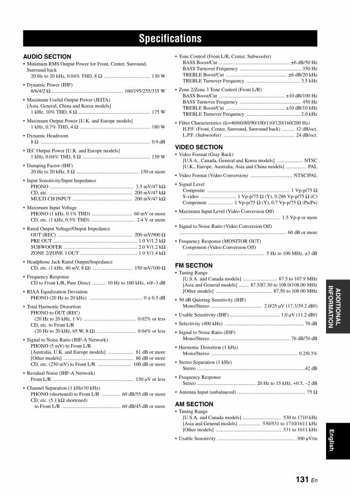
SPECIFICATIONSA
DD
ITIO
NA
L
INF
OR
MA
TIO
NE
ng
lish
AUDIO SECTION• Minimum RMS Output Power for Front, Center, Surround,
Surround back20 Hz to 20 kHz, 0.04% THD, 8 Ω .................................... 130 W
• Dynamic Power (IHF)8/6/4/2 Ω ........................................................ 160/195/255/335 W
• Maximum Useful Output Power (JEITA) [Asia, General, China and Korea models]
1 kHz, 10% THD, 8 Ω ........................................................ 175 W
• Maximum Output Power [U.K. and Europe models]1 kHz, 0.7% THD, 4 Ω ....................................................... 180 W
• Dynamic Headroom8 Ω ...................................................................................... 0.9 dB
• IEC Output Power [U.K. and Europe models]1 kHz, 0.04% THD, 8 Ω ..................................................... 130 W
• Damping Factor (IHF)20 Hz to 20 kHz, 8 Ω ................................................. 150 or more
• Input Sensitivity/Input ImpedancePHONO .................................................................. 3.5 mV/47 kΩCD, etc. ................................................................. 200 mV/47 kΩMULTI CH INPUT ............................................... 200 mV/47 kΩ
• Maximum Input VoltagePHONO (1 kHz, 0.1% THD) ................................ 60 mV or moreCD, etc. (1 kHz, 0.5% THD) .................................. 2.4 V or more
• Rated Output Voltage/Output ImpedanceOUT (REC) ........................................................... 200 mV/900 ΩPRE OUT .................................................................. 1.0 V/1.2 kΩSUBWOOFER .......................................................... 2.0 V/1.2 kΩZONE 2/ZONE 3 OUT ............................................. 1.0 V/1.4 kΩ
• Headphone Jack Rated Output/ImpedanceCD, etc. (1 kHz, 40 mV, 8 Ω) ............................... 150 mV/100 Ω
• Frequency ResponseCD to Front L/R, Pure Direct .......... 10 Hz to 100 kHz, +0/–3 dB
• RIAA Equalization DeviationPHONO (20 Hz to 20 kHz) .......................................... 0 ± 0.5 dB
• Total Harmonic DistortionPHONO to OUT (REC)
(20 Hz to 20 kHz, 1 V) ......................................... 0.02% or lessCD, etc. to Front L/R
(20 Hz to 20 kHz, 65 W, 8 Ω) ............................... 0.04% or less
• Signal to Noise Ratio (IHF-A Network)PHONO (5 mV) to Front L/R[Australia, U.K. and Europe models] .................... 81 dB or more[Other models] ....................................................... 86 dB or moreCD, etc. (250 mV) to Front L/R .......................... 100 dB or more
• Residual Noise (IHF-A Network)Front L/R ............................................................... 150 µV or less
• Channel Separation (1 kHz/10 kHz)PHONO (shortened) to Front L/R ............... 60 dB/55 dB or moreCD, etc. (5.1 kΩ shortened)
to Front L/R .............................................. 60 dB/45 dB or more
• Tone Control (Front L/R, Center, Subwoofer)BASS Boost/Cut ........................................................ ±6 dB/50 HzBASS Turnover Frequency ................................................ 350 HzTREBLE Boost/Cut ................................................ ±6 dB/20 kHzTREBLE Turnover Frequency .......................................... 3.5 kHz
• Zone 2/Zone 3 Tone Control (Front L/R)BASS Boost/Cut .................................................... ±10 dB/100 HzBASS Turnover Frequency ................................................ 450 HzTREBLE Boost/Cut .............................................. ±10 dB/10 kHzTREBLE Turnover Frequency .......................................... 2.0 kHz
• Filter Characteristics (fc=40/60/80/90/100/110/120/160/200 Hz)H.P.F. (Front, Center, Surround, Surround back) .......... 12 dB/oct.L.P.F. (Subwoofer) ........................................................ 24 dB/oct.
VIDEO SECTION• Video Format (Gray Back)
[U.S.A., Canada, General and Korea models] .................... NTSC[U.K., Europe, Australia, Asia and China models] ................ PAL
• Video Format (Video Conversion) ................................. NTSC/PAL
• Signal LevelComposite ................................................................. 1 Vp-p/75 ΩS-video ............................ 1 Vp-p/75 Ω (Y), 0.286 Vp-p/75 Ω (C)Component ................... 1 Vp-p/75 Ω (Y), 0.7 Vp-p/75 Ω (PB/PR)
• Maximum Input Level (Video Conversion Off) ............................................................................... 1.5 Vp-p or more
• Signal to Noise Ratio (Video Conversion Off) .................................................................................... 60 dB or more
• Frequency Response (MONITOR OUT)Component (Video Conversion Off)
............................................................. 5 Hz to 100 MHz, ±3 dB
FM SECTION• Tuning Range
[U.S.A. and Canada models] ........................... 87.5 to 107.9 MHz[Asia and General models] ........ 87.5/87.50 to 108.0/108.00 MHz[Other models] ............................................ 87.50 to 108.00 MHz
• 50 dB Quieting Sensitivity (IHF)Mono/Stereo ........................................ 2.0/25 µV (17.3/39.2 dBf)
• Usable Sensitivity (IHF) ....................................... 1.0 µV (11.2 dBf)
• Selectivity (400 kHz) .............................................................. 70 dB
• Signal to Noise Ratio (IHF)Mono/Stereo .............................................................. 76 dB/70 dB
• Harmonic Distortion (1 kHz)Mono/Stereo .................................................................... 0.2/0.3%
• Stereo Separation (1 kHz) Stereo .....................................................................................42 dB
• Frequency Response Stereo .............................................. 20 Hz to 15 kHz, +0.5, –2 dB
• Antenna Input (unbalanced) ..................................................... 75 Ω
AM SECTION• Tuning Range
[U.S.A. and Canada models] .............................. 530 to 1710 kHz[Asia and General models] ................. 530/531 to 1710/1611 kHz[Other models] ................................................... 531 to 1611 kHz
• Usable Sensitivity ............................................................. 300 µV/m
Specifications
131 En

Specifications
GENERAL• Power Supply
[U.S.A. and Canada models] .............................. AC 120 V, 60 Hz[General and Asia models]
....................................... AC 110/120/220/230–240 V, 50/60 Hz[China model] .................................................... AC 220 V, 50 Hz[Korea model] .................................................... AC 220 V, 60 Hz[Australia model] ............................................... AC 240 V, 50 Hz[U.K. and Europe models] ................................. AC 230 V, 50 Hz
• Power Consumption[U.S.A. and Canada models] ................................. 500 W/630 VA[Other models] ................................................................... 500 W
• Standby Power Consumption[U.S.A. and Canada models] .................................... 0.1 W or less [General model] (AC 240 V, 50 Hz) ...................... 0.33 W or less [Other models] ......................................................... 0.1 W or less
• Maximum Power Consumption [General model only]6ch, 10% THD ................................................................. 1100 W
• AC Outlets[U.S.A. and Canada models] .... 2 (Total 100 W/0.8 A maximum)[Asia, General and China models] ....... 2 (Total 50 W maximum)[Australia model] ......................................... 1 (100 W maximum)[U.K. model] ...................................... 1 (100 W/0.4 A maximum)[Europe model] ......................... 2 (Total 100 W/0.4 A maximum)
• Dimensions (W x H x D) ............................. 435 x 171 x 438.5 mm(17-1/8 x 6-3/4 x 17-1/4 in)
• Weight ........................................................... 17.0 kg (37 lbs. 8 oz.)
* Specifications are subject to change without notice.
132 En

AD
DIT
ION
AL
IN
FO
RM
AT
ION
En
glish
Numerics1 BASIC MENU, Manual setup .......... 722 VOLUME MENU, Manual setup ..... 732ch Enhancer, Sound field program .... 502ch Stereo DIRECT,
Sound field parameter ...................... 692ch Stereo, Sound field programs ........ 502-channel stereo direct, Sound field
parameter ......................................... 693 INPUT MENU, Manual setup .......... 743 SOUND MENU, Manual setup ........ 734 OPTION MENU, Manual setup ....... 747ch Enhancer EFFECT LEVEL .......... 697ch Enhancer, Sound field program .... 507ch Stereo CT LEVEL, Sound field
parameter ......................................... 697ch Stereo PL LEVEL, Sound field
parameter ......................................... 697ch Stereo PR LEVEL, Sound field
parameter ......................................... 697ch Stereo SB LEVEL, Sound field
parameter ......................................... 697ch Stereo SL LEVEL, Sound field
parameter ......................................... 697ch Stereo SR LEVEL, Sound field
parameter ......................................... 697ch Stereo, Sound field programs ........ 507-channel Compressed Music Enhancer
effect level, Sound field parameter ...................... 69
7-channel stereo center speaker level, Sound field parameter ...................... 69
7-channel stereo presence left speaker level, Sound field parameter ............ 69
7-channel stereo presence right speaker level, Sound field parameter ............ 69
7-channel stereo surround back speaker level, Sound field parameter ............ 69
7-channel stereo surround left speaker level, Sound field parameter ............ 69
7-channel stereo surround right speaker level, Sound field parameter ............ 69
96/24 indicator ..................................... 34
AA)DISPLAY SET, Option menu ......... 88A)EQUALIZER, Sound menu ............. 82A)SPEAKER SET, Basic menu ........... 77AC OUTLET(S) .................................. 32Action Game,
Sound field programs ....................... 48Advanced setup .................................. 113Advanced sound configurations ........... 64Adventure, Sound field programs ........ 50AFFAIRS, Radio Data System
program type .................................... 59AM antenna connection ....................... 32AM tuning ............................................ 54AMP, Operation mode selector ........... 36
Audio and video synchronization, Sound menu .....................................84
Audio cable plugs .................................20Audio components connection .............28Audio information ................................44Audio input jacks selection ..................43AUDIO jacks ........................................20Audio jacks ...........................................20AUDIO SELECT .................................43AUDIO SELECT,
Initial configuration .........................91Audio select, Initial configuration ........91Audio settings, Sound menu ................84Audio signal flow .................................23AUTO DELAY, Lip sync ....................84Auto delay, Lip sync ............................84AUTO indicator ...................................35AUTO SETUP .....................................37AUTO setup .........................................72Auto setup ............................................72Automatic preset tuning,
FM/AM tuning .................................55Automatic tuning, FM/AM tuning .......54Available decoders with sound field
programs ..........................................71
BB)LFE LEVEL, Sound menu ...............83B)SP LEVEL, Basic menu ...................79BASIC MENU, Manual setup ..............77Basic menu, Manual setup ...................72Bass cross over, Speaker settings .........78Battery charge indicator .......................34BI-AMP, Advanced setup ..................116Bi-amplifier setting,
Advanced setup ..............................116Blu-ray Disc player connection ............25
CC)DYNAMIC RANGE,
Sound menu .....................................83C)MEMORY GUARD,
Option menu .....................................90C)SP DISTANCE, Basic menu ............80C.IMAGE, Decoder parameter ............71Cable plugs ...........................................20CD player connection ...........................28CD recorder connection .......................28Cellar Club,
Sound field programs .......................48CENTER PRE OUT jack
connection ........................................29CENTER SP, Speaker settings .............77Center speaker, Speaker settings ..........77CENTER WIDTH,
Decoder parameter ...........................71Chamber, Sound field programs ..........47Charge on standby, Dock set ................87Church in Freiburg,
sound field programs ........................47
CINEMA DSP indicator ...................... 35CLASSICAL,
Sound field programs ...................... 47CLASSICS, Radio Data System
program type ................................... 59Clock time, Radio Data System
information ...................................... 58COMPONENT I/P,
Display settings ............................... 89Component interlace/progressive up-
conversion, Display settings ............ 89COMPONENT VIDEO jacks .............. 20Compressed Music Enhancer .............. 50Connection, AM antenna ..................... 32Connection, Audio components .......... 28Connection, Blu-ray Disc player ......... 25Connection, CD player ........................ 28Connection, CD recorder ..................... 28Connection,
CENTER PRE OUT jack ................ 29Connection, DVD player ..................... 26Connection, DVD recorder .................. 27Connection, External amplifier ........... 29Connection, External decoder ............. 30Connection, FM antenna ..................... 32Connection,
FRONT PRE OUT jack ................... 29Connection, HD DVD player .............. 25Connection, iPod ................................. 31Connection, MD recorder .................... 28Connection, Multi-format player ......... 30Connection, Power cable ..................... 32Connection, projector .......................... 24Connection, PVR ................................. 27Connection, Set-top box ...................... 27Connection,
SUBWOOFER PRE OUT jack ....... 29Connection, SUR.BACK/PRESENCE
PRE OUT jack ................................. 29Connection,
SURROUND PRE OUT jack .......... 29Connection, turntable .......................... 28Connection, TV monitor ...................... 24Connection, VCR ................................ 27CROSS OVER, Speaker settings ........ 78CT, Radio Data System
information ...................................... 58CULTURE, Radio Data System
program type ................................... 59
DD)INIT. CONFIG ................................ 91D)LIPSYNC, Sound menu .................. 84D)TEST TONE, Basic menu ............... 80Decoder descriptions ........................... 70Decoder indicators ............................... 35DECODER MODE,
Initial configuration ......................... 91Decoder mode,
Initial configuration ......................... 91
Index
133 En

Index
DECODER MODE, Input menu ......... 86Decoder mode, Input menu .................. 86DIALG.LIFT,
Sound field parameter ...................... 65DIGITAL COAXIAL jacks ................. 20DIGITAL OPTICAL jacks .................. 20DIMENSION, Decoder parameter ...... 71DIMMER, Display settings ................. 88Dimmer, Display settings .................... 88Display settings, Option menu ............. 88DIST, Auto setup parameter ................ 38DRAMA, Radio Data System program
type .................................................. 59Drama, Sound field programs .............. 50DSP indicators ..................................... 35DSP LEVEL, Sound field parameter ... 65DVD player connection ....................... 26DVD recorder connection .................... 27Dynamic range, Sound menu ............... 83
EE)AUDIO SET, Sound menu ............... 84E)ZONE SET, Option menu ................ 91EDUCATE, Radio Data System program
type .................................................. 59Effect sound level,
Sound field parameter ...................... 65Enhanced other networks data service,
Radio Data System tuning ............... 60ENHANCER indicator ........................ 35ENTERTAINMENT, Sound field
programs .......................................... 48EON data service, Radio Data System
tuning ............................................... 60EQ TYPE SELECT, Equalizer ............ 82EQ, Auto setup parameter .................... 40Equalizer type select, Equalizer ........... 82Equalizer, Sound menu ........................ 82EXTD SUR., Initial configuration ....... 91EXTD SUR., Sound menu ................... 84Extended surround,
Initial configuration ......................... 91Extended Surround, Sound menu ........ 84External amplifier connection .............. 29External decoder connection ................ 30
FF)HDMI SET, Sound menu ................. 85FL SCROLL, Display settings ............. 89FM antenna connection ........................ 32FM tuning ............................................ 54Front input,
Multi channel input Setup ............... 87Front panel display scroll,
Display settings ............................... 89Front panel door ................................... 36FRONT PRE OUT connection ............ 29FRONT SP, Speaker settings ............... 77Front speakers, Speaker settings .......... 77FRONT, Multi channel input Setup ..... 87
GGEQ, Equalizer .................................... 82Graphic equalizer, Equalizer ................ 82
GRAY BACK, Display settings ...........88Gray back, Display settings .................88
HHall in Amsterdam,
Sound field programs .......................47Hall in Munich,
Sound field programs .......................47Hall in Vienna,
Sound field programs .......................47HD DVD player connection .................25HDMI ...................................................21HDMI ASPECT ...................................90HDMI aspect ratio ................................90HDMI AUTO, Lip sync .......................84HDMI auto, Lip sync ...........................84HDMI indicator ....................................34HDMI set, Sound menu .......................85HDMI video monitor,
Advanced setup ..............................116HEADPHONE, Dynamic range ...........83HEADPHONE,
Low frequency effect level ..............83Headphones ..........................................43Headphones indicator ...........................35Headphones using ................................43Headphones, Dynamic range ...............83Headphones,
Low frequency effect level ..............83HiFi DSP indicator ...............................35
II/O ASSIGNMENT, Input menu .........86INFO, Radio Data System
program type ....................................59Infrared window ...................................36INI.VOL., Audio settings .....................81INIT.DLY, Sound field parameter .......66Initial configuration, Option menu .......91Initial delay,
Sound field parameter ......................66Initial volume, Audio settings ..............81INITIALIZE, Advanced setup ...........116INPUT CH, Multi channel
input Setup .......................................87Input channel
and speaker indicators ......................34Input channel indicators .......................34Input channels,
Multi channel input Setup ................87INPUT MENU, Manual setup .............85Input menu, Manual setup ....................74INPUT RENAME, Input menu ............86Input rename, Input menu ....................86Input signal indicators ..........................35Input source indicators .........................34Input sources information display ........44Input/output assignment,
Input menu .......................................86iPod connection ....................................31iPod controlling ....................................61iPod using .............................................61
JJacks .....................................................20
LLEVEL, Auto setup parameter .............40LFE/BASS OUT, Speaker settings ......77LFE/Bass out, Speaker settings ............77LIGHT M, Radio Data System
program type ....................................59Lip Sync, Sound menu .........................84LIVE/CLUB,
Sound field programs .......................47LIVENESS,
Sound field parameter ......................67Liveness, Sound field parameter ..........67Low-frequency effect level,
Sound menu ......................................83LVL, Auto setup parameter ..................38
MM.O.R. M, Radio Data System
program type ....................................59Macro programming,
remote control ................................105MANUAL DELAY, Lip sync ..............84Manual delay, Lip sync ........................84Manual preset tuning,
FM/AM tuning .................................55MANUAL SETUP ...............................72Manual setup ........................................72Manual tuning, FM/AM tuning ............54MASTER ON/OFF ...............................33MAX VOL., Audio settings .................81Maximum volume ................................81Maximum volume, Audio settings .......81MD recorder connection .......................28Memory guard, Option menu ...............90MEMORY indicator .............................35MON.CHK, Advanced setup ..............116Mono Movie,
Sound field programs .......................50MOVIE, Sound field programs ............49MULTI CH INPUT
component selection .........................43MULTI CH INPUT jacks .....................30Multi-format player connection ............30Multi-channel source playback
in 2-channel stereo ...........................53Multi-channel sources playback with
headphones .......................................51Multi-information display ....................34MULTI-ZONE configuration,
Zone2, Zone3 .................................108MUSIC ENHANCER, Sound field
category ............................................50Music Video,
Sound field programs .......................49MUTE ...................................................44MUTE indicator ...................................34Muting ..................................................44
NNeo:6 Cinema, Decoder type .........70, 71Neo:6 Music, Decoder type ..................70
134 En

IndexA
DD
ITIO
NA
L
INF
OR
MA
TIO
NE
ng
lish
NEWS, Radio Data System program type .................................... 59
Number of speakers, Auto setup parameter ....................... 38
OON SCREEN, Display settings ............ 88On-screen display time,
Display settings ................................ 88Operation mode selector ...................... 36OPTIMIZER MIC jack ........................ 37Optimizer microphone ......................... 37OPTION MENU, Manual setup .......... 88Option menu, Manual setup ................. 74OSD SHIFT, Display settings .............. 88OSD shift, Display settings .................. 88Other components controlling
by Remote control ........................... 98Other components controlling,
Remote control ................................ 98OTHER M, Radio Data System
program type .................................... 59
PP.INIT.DLY,
Sound field parameter ...................... 66P.ROOM SIZE,
Sound field parameter ...................... 67PANORAMA, Decoder parameter ...... 71Parameter initialization,
Advanced setup .............................. 116Parametric equalizer information ....... 130Parametric equalizer type,
Auto setup parameter ....................... 40PHONES jack ...................................... 43PL II Game, Decoder type ................... 70PL II Movie, Decoder type .................. 70PL II Music, Decoder type ................... 70Playback basic procedure ..................... 42PLIIx Game, Decoder type .................. 70PLIIx Movie, Decoder type ........... 70, 71PLIIx Music, Decoder type .................. 70POP M, Radio Data System
program type .................................... 59Power cable connection ....................... 32Presence initial delay, Sound field
parameter ......................................... 66Presence room size,
Sound field parameter ...................... 67PRESENCE SP, Speaker settings ........ 78Presence speaker indicators ................. 34Presence speakers, Speaker settings .... 78Presence/Surround back channel priority,
Speaker settings ............................... 79Preset stations exchange,
FM/AM tuning ................................. 57Preset stations selection ....................... 56PRIORITY, Speaker settings ............... 79PRO LOGIC, Decoder type ................. 70Program service, Radio Data System
information ...................................... 58Program type, Radio Data System
information ...................................... 58Projector connection ............................ 24
PS, Radio Data System information .......................................58
PTY SEEK mode, Radio Data System tuning ...............................................59
PTY, Radio Data System information .......................................58
PURE DIRECT ....................................52Pure hi-fi sound ....................................52PVR connection ...................................27
RRadio Data System tuning ....................58Radio text, Radio Data System
information .......................................58RC AMP ID, Advanced setup ............114RC TUNER ID, Advanced setup .......114Recital/Opera,
Sound field programs .......................49Remote control AMP ID,
Advanced setup ..............................114Remote control code
default settings .................................99Remote control codes settings ..............99Remote control TUNER ID,
Advanced setup ..............................114Remote control using ...........................36REMOTE IN jack ................................31REMOTE OUT jack ............................31REMOTE SENSOR,
Advanced setup ..............................113Remote sensor, Advanced setup ........113Repeat, iPod playback ..........................62Resetting the system ...........................124REV.DELAY,
Sound field parameter ......................68REV.LEVEL,
Sound field parameter ......................68REV.TIME,
Sound field parameter ......................68Reverberation delay, Sound field
parameter ..........................................68Reverberation level, Sound field
parameter ..........................................68Reverberation time,
Sound field parameter ......................68ROCK M, Radio Data System program
type ...................................................59Roleplaying Game,
Sound field programs .......................48ROOM SIZE,
Sound field parameter ......................67Room size, Sound field parameter .......67RS-232C STANDBY,
Advanced setup ..............................114RT, Radio Data System
information .......................................58
SS VIDEO jacks .....................................20S.INIT.DLY,
Sound field parameter ......................66S.LIVENESS,
Sound field parameter ......................67
S.ROOM SIZE, Sound field parameter ..................... 67
SB INI.DLY, Sound field parameter ..................... 66
SB L/R SP, Speaker settings ............... 78SB LIVENESS,
Sound field parameter ..................... 67SB ROOM SIZE,
Sound field parameter ..................... 67SCIENCE, Radio Data System program
type .................................................. 59Sci-Fi, Sound field programs ............... 49Selection, Audio input jacks ................ 43Selection,
MULTI CH INPUT component ...... 43Selection, Radio Data System
program type ................................... 59SET MENU usage ............................... 76Set-top box connection ........................ 27Short message display,
Display settings ............................... 88SHORT MESSAGE,
Display settings ............................... 88Shuffle iPod playback .......................... 62SIGNAL INFO .................................... 44Signal information ............................... 75SILENT CINEMA ............................... 51SILENT CINEMA indicator ............... 35SLEEP indicator .................................. 35Sleep timer ........................................... 45Sound field indicators .......................... 35Sound field parameter changing .......... 64Sound field programs .......................... 46Sound field programs selection ........... 46Sound field programs
with headphones .............................. 51Sound field programs without surround
speakers ........................................... 51SOUND MENU, Manual setup ........... 82Sound menu, Manual setup ................. 73SOURCE,
Operation mode selector .................. 36SP, Auto setup parameter .................... 38Speaker distance,
Auto setup parameter ...................... 38Speaker distance, Basic menu ............. 80Speaker distances ................................. 80SPEAKER IMP.,
Advanced setup ............................. 113Speaker impedance setting .................. 33Speaker impedance,
Advanced setup ............................. 113Speaker level adjusting ........................ 53Speaker level,
Auto setup parameter ...................... 38Speaker level, Basic menu ................... 79Speaker settings, Basic menu .............. 77SPEAKER, Dynamic range ................. 83SPEAKER, Low frequency
effect level ....................................... 83Speakers, Dynamic range .................... 83Speakers, Low frequency
effect level ....................................... 83Specifications .................................... 131
135 En
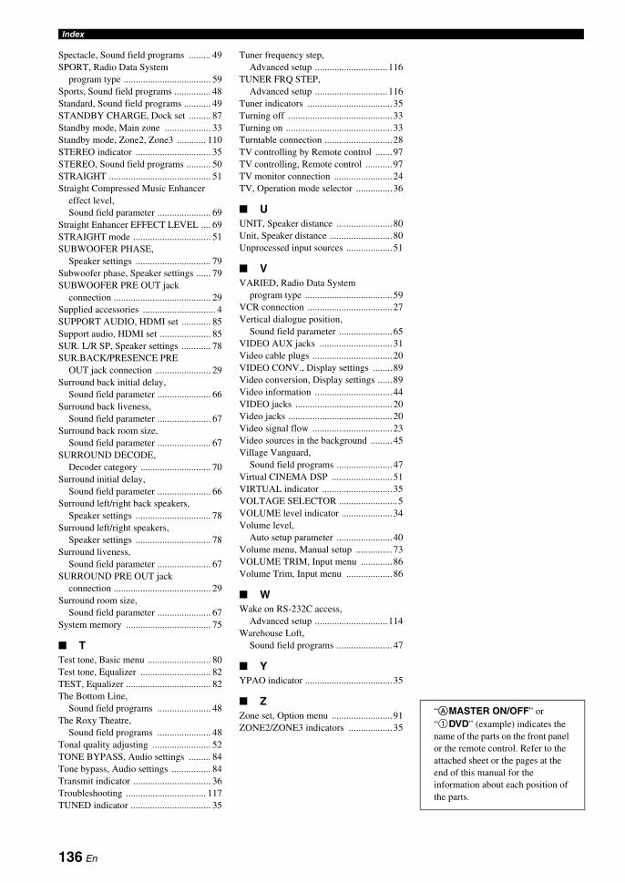
Index
Spectacle, Sound field programs ......... 49SPORT, Radio Data System
program type .................................... 59Sports, Sound field programs ............... 48Standard, Sound field programs ........... 49STANDBY CHARGE, Dock set ......... 87Standby mode, Main zone ................... 33Standby mode, Zone2, Zone3 ............ 110STEREO indicator ............................... 35STEREO, Sound field programs .......... 50STRAIGHT .......................................... 51Straight Compressed Music Enhancer
effect level, Sound field parameter ...................... 69
Straight Enhancer EFFECT LEVEL .... 69STRAIGHT mode ................................ 51SUBWOOFER PHASE,
Speaker settings ............................... 79Subwoofer phase, Speaker settings ...... 79SUBWOOFER PRE OUT jack
connection ........................................ 29Supplied accessories .............................. 4SUPPORT AUDIO, HDMI set ............ 85Support audio, HDMI set ..................... 85SUR. L/R SP, Speaker settings ............ 78SUR.BACK/PRESENCE PRE
OUT jack connection ....................... 29Surround back initial delay,
Sound field parameter ...................... 66Surround back liveness,
Sound field parameter ...................... 67Surround back room size,
Sound field parameter ...................... 67SURROUND DECODE,
Decoder category ............................. 70Surround initial delay,
Sound field parameter ...................... 66Surround left/right back speakers,
Speaker settings ............................... 78Surround left/right speakers,
Speaker settings ............................... 78Surround liveness,
Sound field parameter ...................... 67SURROUND PRE OUT jack
connection ........................................ 29Surround room size,
Sound field parameter ...................... 67System memory ................................... 75
TTest tone, Basic menu .......................... 80Test tone, Equalizer ............................. 82TEST, Equalizer ................................... 82The Bottom Line,
Sound field programs ...................... 48The Roxy Theatre,
Sound field programs ...................... 48Tonal quality adjusting ........................ 52TONE BYPASS, Audio settings ......... 84Tone bypass, Audio settings ................ 84Transmit indicator ................................ 36Troubleshooting ................................. 117TUNED indicator ................................. 35
Tuner frequency step, Advanced setup ..............................116
TUNER FRQ STEP, Advanced setup ..............................116
Tuner indicators ...................................35Turning off ...........................................33Turning on ............................................33Turntable connection ............................28TV controlling by Remote control .......97TV controlling, Remote control ...........97TV monitor connection ........................24TV, Operation mode selector ...............36
UUNIT, Speaker distance .......................80Unit, Speaker distance ..........................80Unprocessed input sources ...................51
VVARIED, Radio Data System
program type ....................................59VCR connection ...................................27Vertical dialogue position,
Sound field parameter ......................65VIDEO AUX jacks ..............................31Video cable plugs .................................20VIDEO CONV., Display settings ........89Video conversion, Display settings ......89Video information ................................44VIDEO jacks ........................................20Video jacks ...........................................20Video signal flow .................................23Video sources in the background .........45Village Vanguard,
Sound field programs .......................47Virtual CINEMA DSP .........................51VIRTUAL indicator .............................35VOLTAGE SELECTOR ........................5VOLUME level indicator .....................34Volume level,
Auto setup parameter .......................40Volume menu, Manual setup ...............73VOLUME TRIM, Input menu .............86Volume Trim, Input menu ...................86
WWake on RS-232C access,
Advanced setup ..............................114Warehouse Loft,
Sound field programs .......................47
YYPAO indicator ....................................35
ZZone set, Option menu .........................91ZONE2/ZONE3 indicators ..................35
“AMASTER ON/OFF” or “1DVD” (example) indicates the name of the parts on the front panel or the remote control. Refer to the attached sheet or the pages at the end of this manual for the information about each position of the parts.
136 En

PRECAUCIÓN: LEA LAS INDICACIONES SIGUIENTES ANTES DE UTILIZAR ESTE APARATO.
Es
1 Para asegurar el mejor rendimiento de este aparato, lea atentamente este manual. Y luego guárdelo en un lugar seguro para poder consultarlo en el futuro en caso de ser necesario.
2 Instale este sistema de sonido en un lugar bien ventilado, fresco, seco y limpio, alejado de la luz solar directa, fuentes de calor, vibración, polvo, humedad y/o frío. Deje un espacio de ventilación de 30 cm como mínimo en la parte superior de la unidad, 20 cm por los lados derecho e izquierdo y 20 cm por la parte trasera.
3 Coloque este aparato lejos de otros aparatos eléctricos, motores o transformadores, para evitar así los ruidos de zumbido.
4 No exponga este aparato a cambios bruscos de temperaturas, del frío al calor, ni lo coloque en lugares muy húmedos (una habitación con deshumidificador, por ejemplo), para impedir así que se forme condensación en su interior, lo que podría causar una descarga eléctrica, un incendio, daños en el aparato y/o lesiones a las personas.
5 Evite instalar este aparato en un lugar donde puedan caerle encima objetos extraños o donde quede expuesto al goteo o a la salpicadura de líquidos. Encima de este aparato no ponga:– Otros componentes, porque pueden causar daños y/o
decoloración en la superficie de este aparato. – Objetos con fuego (velas, por ejemplo), porque pueden
causar un incendio, daños en el aparato y/o lesiones a las personas.
– Recipientes con líquidos, porque pueden caerse y derramar el líquido, causando descargas eléctricas al usuario y/o dañando el aparato.
6 No tape este aparato con un periódico, mantel, cortina, etc. para no impedir el escape del calor. Si aumenta la temperatura en el interior del aparato, esto puede causar un incendio, daños en el aparato y/o lesiones a las personas.
7 No enchufe este aparato a una toma de corriente hasta después de haber terminado todas las conexiones.
8 No ponga el aparato al revés. Podría recalentarse y posiblemente causar daños.
9 No utilice una fuerza excesiva con los conmutadores, los controles y/o los cables.
10 Cuando desconecte el cable de la alimentación de la toma de corriente, sujete la clavija y tire de ella; no tire del propio cable.
11 No limpie este aparato con disolventes químicos porque podría estropear el acabado. Utilice un paño limpio y seco para limpiar el aparato.
12 Utilice solamente la tensión especificada en este aparato. Utilizar el aparato con una tensión superior a la especificada resulta peligroso y puede producir un incendio, daños en el aparato y/o lesiones a las personas. Yamaha no se hará responsable de ningún daño debido al uso de este aparato con una tensión diferente de la especificada.
13 Para impedir daños debidos a relámpagos, desconecte el cable de alimentación de la toma de corriente durante una tormenta eléctrica.
14 No intente modificar ni arreglar este aparato. Póngase en contacto con el personal de servicio Yamaha cualificado cuando necesite realizar alguna reparación. La caja no deberá abrirse nunca por ninguna razón.
15 Cuando no piense utilizar este aparato durante mucho tiempo (es decir, cuando se ausente de casa por vacaciones, etc.) desconecte el cable de alimentación de la toma de corriente.
16 Instale esta unidad cerca de la toma de CA y donde se pueda alcanzar fácilmente la clavija de alimentación de CA.
17 Asegúrese de leer la sección “Solución de problemas” antes de dar por concluido que su aparato está averiado.
18 Antes de trasladar esta unidad, pulse AMASTER ON/OFF para soltarlo y ponerlo en la posición OFF y apagar esta unidad, la habitación principal, Zone 2 y Zone 3, y luego desconecte la clavija de alimentación de CA de la toma de CA.
19 VOLTAGE SELECTOR (Modelos de Asia y Generale solamente)El selector VOLTAGE SELECTOR del panel posterior de este aparato deberá ponerse en la posición correspondiente a la tensión empleada en su localidad ANTES de conectar el aparato a la red de alimentación de CA. Las tensiones son:.....................................CA 110/120/220/230–240 V, 50/60 Hz
20 Las pilas no deberán exponerse a un calor excesivo como, por ejemplo, la luz solar directa, el fuego o algo similar.
21 La presión acústica excesiva de los auriculares puede causar pérdida auditiva.
Precaución: Lea las indicaciones siguientes antes de utilizar este aparato.
ADVERTENCIAPARA REDUCIR EL RIESGO DE INCENDIO O DESCARGA ELÉCTRICA, NO EXPONGA ESTA UNIDAD A LA LLUVIA NI A LA HUMEDAD.
Aunque usted apague esta unidad con AMASTER ON/OFF, esta unidad no se desconectará de la fuente de alimentación de CA mientras esté conectada a la toma de CA. En este estado, esta unidad ha sido diseñada para que consuma una cantidad de corriente muy pequeña.
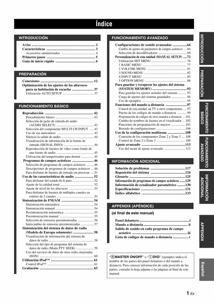
1 Es
PR
EPA
RA
CIÓ
NIN
TR
OD
UC
CIÓ
NIN
FO
RM
AC
IÓN
A
DIC
ION
AL
AP
PE
ND
IXFU
NC
ION
AM
IENTO
B
ÁSIC
OFU
NC
ION
AM
IENTO
AVA
NZA
DO
Esp
año
l
Aviso ........................................................................ 2Características ....................................................... 3
Accesorios suministrados ......................................... 4Primeros pasos ....................................................... 5Guía de inicio rápido ............................................. 6
Conexiones ............................................................ 12Optimización de los ajustes de los altavoces
para su habitación de escucha ........................ 37Utilización AUTO SETUP ..................................... 37
Reproducción ....................................................... 42Procedimiento básico .............................................. 42Selección de jacks de entrada de audio
(AUDIO SELECT) ............................................. 43Selección del componente MULTI CH INPUT ..... 43Uso de sus auriculares ............................................ 43Silencia la salida de audio ....................................... 44Visualización de información de la fuente de
entrada (SIGNAL INFO) .................................... 44Reproducción de fuentes de vídeo como fondo de
una fuente de audio ............................................. 45Utilización del temporizador para dormir ............... 45
Programas de campos acústicos ........................ 46Selección de programas de campos acústicos ........ 46Descripciones de programas de campos acústicos ... 46Para disfrutar de fuentes de entrada sin procesar .... 51
Uso de las características de audio ..................... 52Para disfrutar del sonido hi-fi puro ......................... 52Ajuste de la calidad tonal ........................................ 52Ajuste de nivel de los altavoces .............................. 53Para disfrutar de fuentes de múltiples canales en
estéreo de 2 canales ............................................ 53Sintonización de FM/AM .................................... 54
Sintonización automática ........................................ 54Sintonización manual .............................................. 54Presintonización automática ................................... 55Presintonización manual ......................................... 55Selección de emisoras presintonizadas ................... 56Intercambio de emisoras presintonizadas ............... 57
Sintonización del sistema de datos de radio (Modelo de Europa solamente) ....................... 58Visualización de información del sistema de
datos de radio ...................................................... 58Selección del tipo de programa del sistema de
datos de radio (Modo PTY SEEK) ..................... 59Uso del servicio de datos de otras redes mejoradas
(EON) ................................................................. 60Utilización iPod™ ................................................ 61
Control iPod™ ........................................................ 61Grabación ............................................................. 63
Configuraciones de sonido avanzadas ................64Cambio de ajustes de parámetros de campos acústicos ... 64Selección de decodificadores .................................. 69
Personalización de esta unidad (MANUAL SETUP) ....72Utilización SET MENU .......................................... 761 BASIC MENU ..................................................... 772 VOLUME MENU ............................................... 813 SOUND MENU ................................................... 824 INPUT MENU ..................................................... 855 OPTION MENU .................................................. 88
Para guardar y recuperar los ajustes del sistema (SYSTEM MEMORY) .......................................93Para guardar los ajustes actuales del sistema .......... 93Carga de ajustes del sistema guardados .................. 94Uso de ejemplos ...................................................... 95
Funciones del mando a distancia ........................97Control de esta unidad, un TV u otros componentes .... 97Puesta de los códigos de mando a distancia ........... 99Programación de códigos de otros mandos a distancia ... 101Cambio de nombres de fuentes en el visualizador ... 102Funciones de programación de macros ................. 103Borrado de configuraciones .................................. 106
Uso de la configuración multizona ....................108Conexión de los componentes Zone 2 y Zone 3 .... 108Control de Zone 2 o Zone 3 .................................. 109
Ajuste avanzado .................................................113Uso del menú de ajuste avanzado ......................... 113
Solución de problemas .......................................117Reposición del sistema .......................................124Glosario ...............................................................125Información de programas de campos acústicos ......129Información de ecualizador paramétrico .........130Especificaciones ..................................................131Índice alfabético .................................................133
(al final de este manual)
Panel delantero .........................................................iMando a distancia .................................................. iiSalida de sonido en cada programa de campo
acústico .............................................................. iiiLista de códigos de mando a distancia ..................v
Índice
INTRODUCCIÓN
PREPARACIÓN
FUNCIONAMIENTO BÁSICO
FUNCIONAMIENTO AVANZADO
INFORMACIÓN ADICIONAL
APPENDIX (APÉNDICE)
“AMASTER ON/OFF” o “1DVD” (ejemplo) indica el nombre de las partes del panel delantero o del mando a distancia. Para conocer información de cada posición de las partes, consulte la hoja adjunta o las páginas al final de este manual.

AVISO
Fabricado bajo licencia de Dolby Laboratories.“Dolby”, “Pro Logic” y el símbolo con una doble D son marcas registradas de Dolby Laboratories.
Fabricado bajo licencia según patentes de los EE.UU. con los números: 5,451,942;5,956,674;5,974,380;5,978,762;6,226,616;6,487,535, y otras patentes de los EE.UU. e internacionales emitidas o pendientes. DTS es una marca registrada, y los logotipos DTS, el símbolo, DTS-HD y DTS-HD Master Audio son marcas de fábrica de DTS, Inc. © 1996-2007 DTS, Inc. Todos los derechos reservados.
“iPod” es una marca de fábrica de Apple Inc., registrada en los EE.UU. y en otros países.
“HDMI”, el logotipo “HDMI” y “High-Definition Multimedia Interface” son marcas de fábrica o marcas registradas de HDMI Licensing LLC.
“SILENT CINEMA” es una marca de fábrica de YAMAHA CORPORATION.
Aviso
Acerca de este manual
• y indica un consejo para su utilización.• Algunas operaciones se pueden llevar a cabo con los
botones del panel delantero o del mando a distancia. Cuando los nombres de los botones del panel delantero y del mando a distancia sean diferentes, los nombres de los botones del mando a distancia estarán entre parentesis.
• Este manual se imprime antes de la producción. El diseño y las especificaciones están sujetos a cambios por motivo de mejoras, etc. Si hay diferencias entre el manual y el producto, el producto tiene prioridad.
• “AMASTER ON/OFF” o “1DVD” (ejemplo) indica el nombre de las partes del panel delantero o del mando a distancia. Para conocer información de cada posición de las partes, consulte la hoja adjunta o las páginas al final de este manual.
• El símbolo “ ” con el número de página indica la página de referencia correspondiente.
• Las ilustraciones de este manual (por ejemplo, los terminales de altavoces, los jacks de entrada/salida, las tomas de CA, etc.) pueden cambiar según el modelo.
iPodTM
2 Es

CARACTERÍSTICASIN
TR
OD
UC
CIÓ
NE
spañ
ol
Amplificador de potencia de 7 canales incorporado Potencia de salida RMS mínima
(20 Hz a 20 kHz, 0,04% THD, 8 Ω)Delanteros: 130 W + 130 WCentral: 130 WSurround: 130 W + 130 WSurround trasero: 130 W + 130 W
Programas de campos acústicos Tecnología para la creación de campos acústicos patentada
por Yamaha Modo Compressed Music Enhancer para mejorar la calidad
del sonido de artefactos de compresión (tal como el formato MP3) y alcanzar la de la reproducción de fuentes de múltiples canales de alta calidad.
Virtual CINEMA DSP SILENT CINEMA
Decodificadores de audio digital Decodificador Dolby TrueHD, Dolby Digital Plus Decodificador DTS-HD Master Audio, DTS-HD High
Resolution Audio Decodificador Dolby Digital/Dolby Digital EX Decodificador DTS/DTS-ES Matrix 6.1, Discrete 6.1, DTS
96/24 Decodificador Dolby Pro Logic/Dolby Pro Logic II/Dolby Pro
Logic IIx DTS Decodificador NEO:6
Sofisticado sintonizador de FM/AM Sintonización aleatoria y directa de 40 emisoras
presintonizadas Sintonización automática de emisoras presintonizadas Capacidad de cambio de emisoras presintonizadas (edición de
presintonización) Capacidad para el sistema de datos de radio (Modelo de
Europa solamente)
HDMI™ (Interfaz multimedia de alta definición) Interfaz HDMI para obtener vídeo estándar, realzado o de alta
definición y también audio digital multicanal basado en HDMI versión 1.3a
Capacidad para información de sincronización automática de audio y vídeo (sincronización de voz)
Deep Color Capacidad para transmisión de señales de vídeo (30/36 bits)
Capacidad para frecuencia de renovación alta y señales de vídeo de alta resolución
Capacidad para señales del formato de audio digital de alta definición
Conversión ascendente de vídeo analógico a vídeo digital HDMI (vídeo compuesto ↔ S-vídeo ↔ vídeo componente → vídeo digital HDMI) para salida de monitor
Escalado ascendente de vídeo analógico de 480i (NTSC)/576i (PAL) o 480p/576p a 720p, 1080i o 1080p
Capacidad para controlar iPod™ Terminal DOCK para conectar un acoplador universal
Yamaha iPod (como el YDS-10, vendido separadamente) que soporta iPod (Click and Wheel), iPod nano y iPod mini
Otras características YPAO (Yamaha Parametric Room Acoustic Optimizer) para
la instalación automática de los altavoces Convertidor D/A de 192 kHz/24 bits Menús OSD (visualización en pantalla) que le permiten
optimizar esta unidad para adaptarla a su sistema audiovisual individual
6 u 8 jacks de entrada adicionales para obtener una entrada multicanal discreta
Conversión de vídeo analógico entrelazado/progresivo de 480i (NTSC)/576i (PAL) a 480p/576p
Capacidad de entrada/salida de señal de S-vídeo Capacidad de entrada/salida de vídeo componente
(3 COMPONENT VIDEO INs y 1 MONITOR OUT) Jacks coaxiales y ópticos para señales de audio digital Modo Pure Direct para obtener un sonido hi-fi puro para todas
las fuentes Capacidad para controlar la gama dinámica adaptiva Capacidad para controlar el nivel del efecto DSP adaptivo Mando a distancia con códigos de mando a distancia
preestablecidos y capacidad de aprendizaje y macro Instalación personalizada ZONE 2/ZONE 3 Capacidad de cambio de zona entre zona principal y ZONE 2/
ZONE 3 usando ZONE CONTROLS Capacidad SYSTEM MEMORY para guardar y recuperar
ajustes de parámetros de múltiples sistemas Temporizador para dormir
Características
3 Es

Características
Verifique que ha recibido todos los accesorios siguientes.
La forma de los accesorios suministrados cambia según los modelos.
Accesorios suministrados
Nota
Mando a distanciaPilas (6)
(AAA, R03, UM-4)(excepto para el modelo de Europa)
Antena de cuadro de AM
Micrófono optimizadorLlave para terminales de altavoces
Cables de alimentación(Dos para el modelo de Asia)
Antena de FM interior
TUNER CD CD-R
MD/TAPE DVD BD/HD DVD PHONO
DTV/CBL VCR V-AUX/DOCKDVR
POWER
STANDBY
A/B/C/D/E
PRESET VOLUME
ZONE 3ZONE 2ID2ID1
MUTE
Mando a distancia Zone 2/Zone 3
(excepto para el modelo de Europa)
Pilas (4)(AAA, R03, UM-4)
(Modelo de Europa)
Pilas (4)(AAA, R03, UM-4)
(Modelo de Europa)
–
+ +
––
+
ENTER
DISPLAY
AUDIO
MENUTITLE
TV MUTE TV INPUT MUTE
432
ENT+1009
5
1
AVTV
76 8
RETURN
ONOFF CLEARLEARN RENAMEMACRO
REC
DISC SKIP
VOLUMECHTV VOL
EFFECT
PARAMETER
FREQ/TEXT EON MODE – PTY SEEK – START
STRAIGHTA/B/C/D/E
SRCH MODE
PURE DIRECTPRESET/CH
SET MENU
BAND
LEVEL
CLASSICAL LIVE/CLUB ENTERTAIN MOVIE
SYSTEM MEMORY
SUR. DECODEENHANCERSTEREO
TV
SOURCE
AMP
SELECT
DTV/CBL VCRDVR V-AUX/DOCK
TUNER CD CD-R MULTI CH IN
POWER POWER POWERSTANDBY
SLEEPAUDIO SEL
DVD BD/HD DVD PHONOMD/TAPE
4 Es
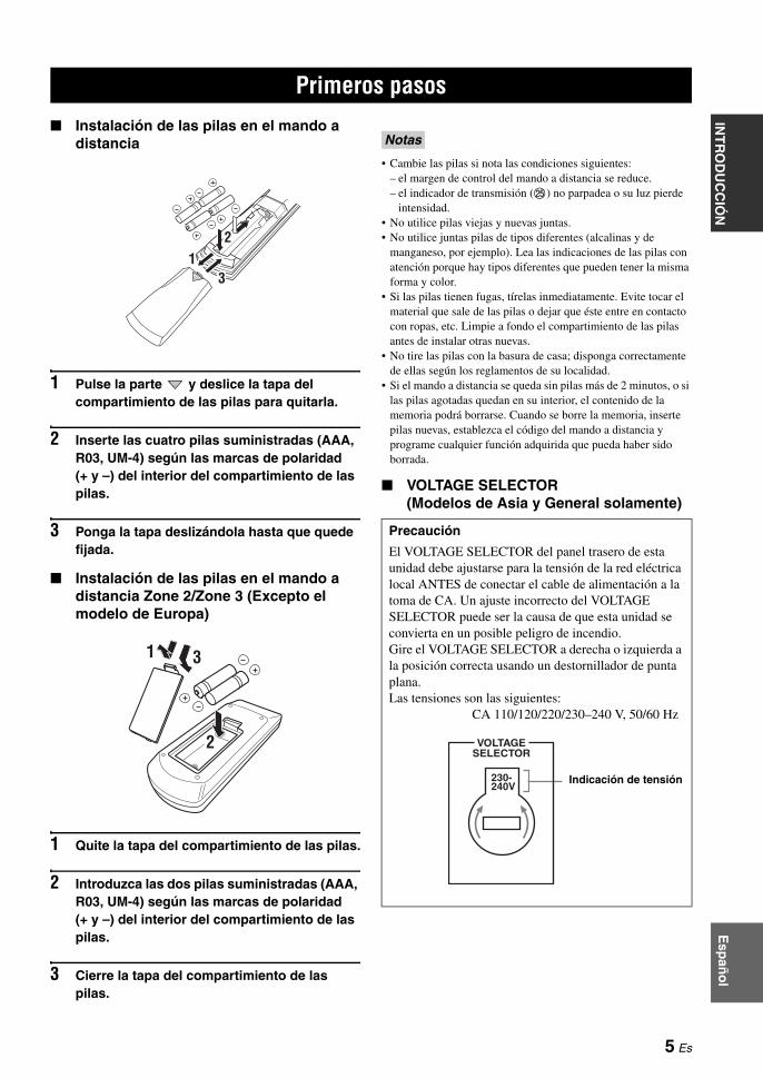
PRIMEROS PASOSIN
TR
OD
UC
CIÓ
NE
spañ
ol
Instalación de las pilas en el mando a distancia
1 Pulse la parte y deslice la tapa del compartimiento de las pilas para quitarla.
2 Inserte las cuatro pilas suministradas (AAA, R03, UM-4) según las marcas de polaridad (+ y –) del interior del compartimiento de las pilas.
3 Ponga la tapa deslizándola hasta que quede fijada.
Instalación de las pilas en el mando a distancia Zone 2/Zone 3 (Excepto el modelo de Europa)
1 Quite la tapa del compartimiento de las pilas.
2 Introduzca las dos pilas suministradas (AAA, R03, UM-4) según las marcas de polaridad (+ y –) del interior del compartimiento de las pilas.
3 Cierre la tapa del compartimiento de las pilas.
• Cambie las pilas si nota las condiciones siguientes:– el margen de control del mando a distancia se reduce.– el indicador de transmisión (O) no parpadea o su luz pierde
intensidad.• No utilice pilas viejas y nuevas juntas.• No utilice juntas pilas de tipos diferentes (alcalinas y de
manganeso, por ejemplo). Lea las indicaciones de las pilas con atención porque hay tipos diferentes que pueden tener la misma forma y color.
• Si las pilas tienen fugas, tírelas inmediatamente. Evite tocar el material que sale de las pilas o dejar que éste entre en contacto con ropas, etc. Limpie a fondo el compartimiento de las pilas antes de instalar otras nuevas.
• No tire las pilas con la basura de casa; disponga correctamente de ellas según los reglamentos de su localidad.
• Si el mando a distancia se queda sin pilas más de 2 minutos, o si las pilas agotadas quedan en su interior, el contenido de la memoria podrá borrarse. Cuando se borre la memoria, inserte pilas nuevas, establezca el código del mando a distancia y programe cualquier función adquirida que pueda haber sido borrada.
VOLTAGE SELECTOR(Modelos de Asia y General solamente)
Primeros pasos
13
2
1 3
2
Notas
Precaución
El VOLTAGE SELECTOR del panel trasero de esta unidad debe ajustarse para la tensión de la red eléctrica local ANTES de conectar el cable de alimentación a la toma de CA. Un ajuste incorrecto del VOLTAGE SELECTOR puede ser la causa de que esta unidad se convierta en un posible peligro de incendio.Gire el VOLTAGE SELECTOR a derecha o izquierda a la posición correcta usando un destornillador de punta plana.Las tensiones son las siguientes: CA 110/120/220/230–240 V, 50/60 Hz
230-240V
VOLTAGESELECTOR
Indicación de tensión
5 Es

GUÍA DE INICIO RÁPIDO
Los pasos siguientes describen la forma más sencilla de disfrutar de la reproducción de películas de DVD en su cine de casa.
En estos pasos necesita los accesorios suministrados siguientes.
Antena de cuadro de AM Antena de FM interior Cable de alimentación
Los elementos siguientes no se incluyen en el paquete de esta unidad.
Altavoces altavoz delantero ................................ x 2 Altavoz central ................................... x 1 Altavoz surround ............................... x 4Seleccione altavoces con blindaje antimagnético. Se necesitan como mínimo dos altavoces delanteros. El orden de prioridad de los demás altavoces requeridos es el siguiente:
1. Dos altavoces surround2. Un altavoz central3. Un altavoz surround trasero (o dos)
Altavoz de subgraves activo ................. x 1Seleccione un altavoz de subgraves activo que tenga jack de entrada RCA.
Cable de altavoz ..................................... x 7 Cable de altavoz de subgraves ............. x 1
Seleccione un cable RCA monofónico.
Reproductor DVD ................................... x 1Seleccione un reproductor DVD con jack coaxial de salida de audio digital y jack de salida de vídeo compuesto.
Monitor de vídeo ..................................... x 1Seleccione un monitor de TV, monitor de vídeo o proyector equipado con un jack de entrada de vídeo compuesto.
Cable de vídeo ........................................ x 2Seleccione cables de vídeo compuesto RCA.
Cable coaxial de audio digital ............... x 1
Guía de inicio rápido
Altavoz delantero derecho
Altavoz de subgraves
Altavoz surround trasero derecho
Altavoz surround izquierdo
Altavoz delantero izquierdo
Altavoz surround trasero izquierdo
Altavoz surround derecho
Altavoz central
Monitor de vídeo
Reproductor DVD
¡Disfrute de la reproducción de DVD!
Paso 1: Instalación de sus altavoces
P. 7
Paso 2: Conecte su reproductor DVD y otros componentes
Paso 3: Conecte la alimentación e inicie la reproducción
P. 8
P. 10
Preparación: Verifique los elementos
6 Es
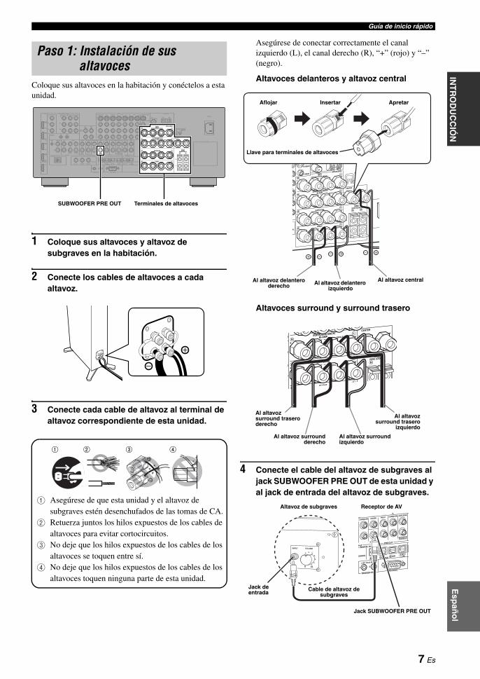
Guía de inicio rápidoIN
TR
OD
UC
CIÓ
NE
spañ
ol
Coloque sus altavoces en la habitación y conéctelos a esta unidad.
1 Coloque sus altavoces y altavoz de subgraves en la habitación.
2 Conecte los cables de altavoces a cada altavoz.
3 Conecte cada cable de altavoz al terminal de altavoz correspondiente de esta unidad.
1 Asegúrese de que esta unidad y el altavoz de subgraves estén desenchufados de las tomas de CA.
2 Retuerza juntos los hilos expuestos de los cables de altavoces para evitar cortocircuitos.
3 No deje que los hilos expuestos de los cables de los altavoces se toquen entre sí.
4 No deje que los hilos expuestos de los cables de los altavoces toquen ninguna parte de esta unidad.
Asegúrese de conectar correctamente el canal izquierdo (L), el canal derecho (R), “+” (rojo) y “–” (negro).
Altavoces delanteros y altavoz central
Altavoces surround y surround trasero
4 Conecte el cable del altavoz de subgraves al jack SUBWOOFER PRE OUT de esta unidad y al jack de entrada del altavoz de subgraves.
Paso 1: Instalación de sus altavoces
AC IN
AC OUTLETS
HOLDERWRENCH
SPEAKERS
CENTERBI-AMP
SURROUND BACK/
PRESENCE/ZONE 2/ZONE 3SP1
FRONT
SURROUNDZONE 2/ZONE 3
SINGLE
SP2
ANTENNA
FM GND AM75Ω UNBAL.
VIDEO
S VIDEO
MONITOR OUTVIDEO
REMOTE
PHONOGND CD
IN(PLAY) OUT(REC)
CD-R
HDMI COMPONENT VIDEO
AUDIODOCK DIGITAL INPUT
MULTI CH INPUT PRE OUT
TRIGGER OUT RS-232C
DIGITAL OUTPUTZONE OUT
SUBWOOFER
SUBWOOFER
CENTER CENTERFRONT(6CH) FRONTSURROUND SURROUND
PRESENCESUR.BACK/
SINGLE(SB) ZONE 2 ZONE 3
CD DVD DVR
COAXIAL
1 2
CD BD/HD DVD
DTV/CBL
MD/ TAPEDVD CD-R
OPTICAL
987654321
SB(8CH)
DVD
TAPEMD/
(REC)(PLAY)IN OUT
BD/HD DVD VCRDVRDTV/CBL OUT OUTININBD/HD DVD DVD DTV/CBLMONITOR OUT
Y
PR
Y
PR
PB PB
IN OUT
DVR
DTV/CBL
DVD
BD/HD DVD
OUT
+
+ +
A B C
R L
R
R
L
R
L
+ + +R L
+ +R L
+ +R L
L
IN2
IN3
IN4
IN1
SUBWOOFER PRE OUT Terminales de altavoces
1 2 3 4
1 2 3 4
Al altavoz delantero izquierdo
Al altavoz delantero derecho
Aflojar Insertar Apretar
Al altavoz central
Llave para terminales de altavoces
Al altavoz surround trasero derecho
Al altavozsurround trasero
izquierdo
Al altavoz surroundderecho
Al altavoz surround izquierdo
Jack SUBWOOFER PRE OUT
Jack de entrada
Receptor de AVAltavoz de subgraves
Cable de altavoz de subgraves
7 Es
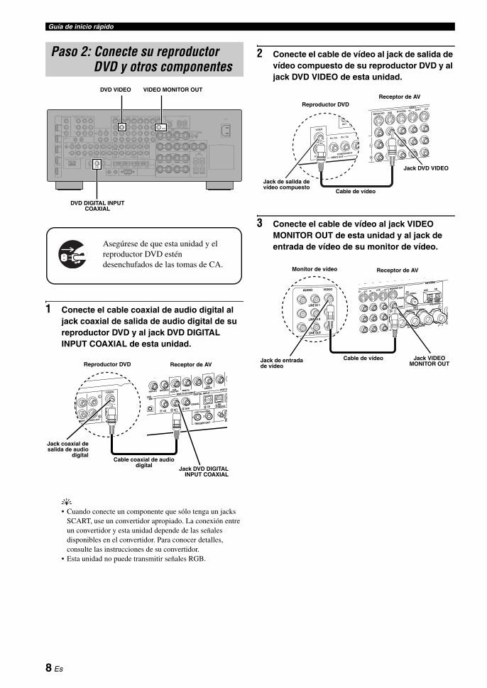
Guía de inicio rápido
1 Conecte el cable coaxial de audio digital al jack coaxial de salida de audio digital de su reproductor DVD y al jack DVD DIGITAL INPUT COAXIAL de esta unidad.
y• Cuando conecte un componente que sólo tenga un jacks
SCART, use un convertidor apropiado. La conexión entre un convertidor y esta unidad depende de las señales disponibles en el convertidor. Para conocer detalles, consulte las instrucciones de su convertidor.
• Esta unidad no puede transmitir señales RGB.
2 Conecte el cable de vídeo al jack de salida de vídeo compuesto de su reproductor DVD y al jack DVD VIDEO de esta unidad.
3 Conecte el cable de vídeo al jack VIDEO MONITOR OUT de esta unidad y al jack de entrada de vídeo de su monitor de vídeo.
Paso 2: Conecte su reproductor DVD y otros componentes
AC IN
AC OUTLETS
HOLDERWRENCH
SPEAKERS
CENTERBI-AMP
SURROUND BACK/
PRESENCE/ZONE 2/ZONE 3SP1
FRONT
SURROUNDZONE 2/ZONE 3
SINGLE
SP2
ANTENNA
FM GND AM75Ω UNBAL.
VIDEO
S VIDEO
MONITOR OUTVIDEO
REMOTE
PHONOGND CD
IN(PLAY) OUT(REC)
CD-R
HDMI COMPONENT VIDEO
AUDIODOCK DIGITAL INPUT
MULTI CH INPUT PRE OUT
TRIGGER OUT RS-232C
DIGITAL OUTPUTZONE OUT
SUBWOOFER
SUBWOOFER
CENTER CENTERFRONT(6CH) FRONTSURROUND SURROUND
PRESENCESUR.BACK/
SINGLE(SB) ZONE 2 ZONE 3
CD DVD DVR
COAXIAL
1 2
CD BD/HD DVD
DTV/CBL
MD/ TAPEDVD CD-R
OPTICAL
987654321
SB(8CH)
DVD
TAPEMD/
(REC)(PLAY)IN OUT
BD/HD DVD VCRDVRDTV/CBL OUT OUTININBD/HD DVD DVD DTV/CBLMONITOR OUT
Y
PR
Y
PR
PB PB
IN OUT
DVR
DTV/CBL
DVD
BD/HD DVD
OUT
+
+ +
A B C
R L
R
R
L
R
L
+ + +R L
+ +R L
+ +R L
L
IN2
IN3
IN4
IN1
Asegúrese de que esta unidad y el reproductor DVD estén desenchufados de las tomas de CA.
VIDEO MONITOR OUTDVD VIDEO
DVD DIGITAL INPUT COAXIAL
Jack coaxial desalida de audio
digitalCable coaxial de audio
digitalJack DVD DIGITAL
INPUT COAXIAL
Reproductor DVD Receptor de AV
Jack de salida de vídeo compuesto
Cable de vídeo
Jack DVD VIDEO
Reproductor DVDReceptor de AV
Monitor de vídeo Receptor de AV
Cable de vídeo Jack VIDEO MONITOR OUT
Jack de entrada de vídeo
8 Es

Guía de inicio rápidoIN
TR
OD
UC
CIÓ
NE
spañ
ol
4 Conecte la antena de cuadro de AM y la antena de FM interior, ambas suministradas, a esta unidad.
Los tipos de los terminales de la antena de FM interior suministrada y de otras antenas de FM son distintos según los modelos.
Conexión del cable de la antena de cuadro de AM
yEl cable de la antena de cuadro de AM no tiene ninguna polaridad, pudiendo usted conectarlo por cualquiera de sus extremos al terminal AM o GND.
Montaje de la antena de cuadro de AM suministrada
5 Conecte el cable de alimentación suministrado a esta unidad y luego enchufe el cable de alimentación y otros componentes en una toma de CA.
y• Esta unidad está equipada con AC OUTLET(S) para
suministrar alimentación a otros componentes (excepto el modelo de Corea). Vea la página 32 para conocer detalles.
• (Modelo de Asia solamente) Antes de conectar esta unidad a una toma de CA, seleccione uno de los cables de alimentación suministrados que sea apropiado para conectarlo a dicha toma de CA.
Nota
Antena de FM interior
Antena de cuadro de AM
Mantenga pulsada la lengüeta
Insertar Suelte la lengüeta
Para hacer más conexiones
• Uso de otras combinaciones de altavoces P. 14
• Conexión de diversas formas de un monitor de vídeo P. 24
• Conexión de diversas formas de un reproductor DVD P. 25
• Conexión de una grabadora DVD o una videograbadora digital P. 27
• Conexión de un receptor digital multimedia P. 27
• Conexión de un reproductor CD, una grabadora MD o un giradiscos P. 28
• Conexión de un amplificador externo P. 29
• Conexión de un reproductor DVD mediante conexión multicanal de audio analógico P. 30
• Conexión de un acoplador universal Yamaha iPod P. 31
• Uso de los jacks REMOTE IN/OUT P. 31
• Uso de los jacks VIDEO AUX del panel delantero P. 31
• Conexión de una antena exterior de FM/AM P. 32
Información de conexión general
• Información general sobre jacks y clavijas de cables P. 20
• Información general sobre HDMI P. 21–22
• Ajuste de impedancia de altavoces P. 33
9 Es
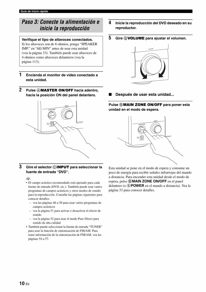
Guía de inicio rápido
1 Encienda el monitor de vídeo conectado a esta unidad.
2 Pulse AMASTER ON/OFF hacia adentro, hacia la posición ON del panel delantero.
3 Gire el selector CINPUT para seleccionar la fuente de entrada “DVD”.
y• El campo acústico recomendado está ajustado para cada
fuente de entrada (DVD, etc.). También puede usar varios programas de campos acústicos y otros modos de sonido para la reproducción. Consulte las páginas siguientes para conocer detalles:– vea las páginas 46 a 50 para usar varios programas de
campos acústicos– vea la página 51 para activar o desactivar el efecto de
sonido– vea la página 52 para usar el modo Pure Direct para
sonido de alta calidad• También puede seleccionar la fuente de entrada “TUNER”
para usar la función de sintonización de FM/AM. Para tener información de la sintonización de FM/AM, vea las páginas 54 a 57.
4 Inicie la reproducción del DVD deseado en su reproductor.
5 Gire QVOLUME para ajustar el volumen.
Después de usar esta unidad...
Pulse BMAIN ZONE ON/OFF para poner esta unidad en el modo de espera.
Esta unidad se pone en el modo de espera y consume un poco de energía para recibir señales infrarrojas del mando a distancia. Para encender esta unidad desde el modo de espera, pulse BMAIN ZONE ON/OFF en el panel delantero (o 8POWER en el mando a distancia). Vea la página 33 para conocer detalles.
Paso 3: Conecte la alimentación e inicie la reproducción
Verifique el tipo de altavoces conectados.Si los altavoces son de 6 ohmios, ponga “SPEAKER IMP.” en “6Ω MIN” antes de usar esta unidad (vea la página 33). También puede usar altavoces de 4 ohmios como altavoces delanteros (vea la página 113).
10 Es

Guía de inicio rápidoIN
TR
OD
UC
CIÓ
NE
spañ
ol
¿Qué quiere hacer con esta unidad?
Uso de varias fuentes de entrada
• Operaciones básicas de esta unidad P. 42
• Disfrute de programas de radio de FM/AM P. 54
• Para disfrutar de programas del sistema de datos de radio P. 58
• Uso de su iPod con esta unidad P. 61
Uso de varias funciones de sonido
• Uso de varios programas de campos acústicos P. 46
• Uso del modo Pure Direct para obtener sonido de alta fidelidad P. 52
• Ajuste de la calidad tonal de los altavoces P. 52
• Personalización de programas de campos acústicos P. 64
Ajuste de los parámetros de esta unidad
• Optimización automática de los parámetros de los altavoces para su habitación de escucha (AUTO SETUP) P. 37
• Ajuste del mando a distancia P. 97
Características adicionales
• Visualización de información de las señales de la fuente de entrada actual en la OSD P. 44
• Para guardar y recuperar los ajustes del sistema de esta unidad (SYSTEM MEMORY) P. 93
• Utilización de auriculares P. 43
• Utilización simultánea de esta unidad en múltiples habitaciones (configuración multizona) P. 108
• Apagado automático de esta unidad P. 45
Ajuste manual de varios parámetros de esta unidad
• Ajuste de la configuración básica de los altavoces P. 77
• Ajuste del balance de los niveles de los altavoces P. 79
• Ajuste de la distancia de cada altavoz P. 80
• Ajuste de los parámetros relacionados con el nivel del sonido P. 81
• Ajuste de la calidad tonal usando el ecualizador gráfico P. 82
• Ajuste de la función de sincronización de voz para la conexión HDMI P. 84
• Asignación de los jacks de entrada/salida de esta unidad P. 86
• Ajuste de los parámetros del visualizador del panel delantero o de la OSD P. 88
• Ajuste de los parámetros relacionados con las señales de vídeo P. 89
• Protección de varios ajustes P. 90
• Ajuste de los parámetros de la característica multizona P. 91
Ajuste de parámetros avanzados
• Ajuste de la impedancia de los altavoces conectados P. 113
• Ajuste de los parámetros de esta unidad a los valores predeterminados P. 116
11 Es

0 Jacks TRIGGER OUTÉstos son terminales de expansión de control para instalación personalizada.
A Terminal RS-232CÉste es un terminal de expansión de control para usar en fábrica solamente. Consulte a su concesionario para conocer detalles.
Conexiones
Panel trasero
AC IN
AC OUTLETS
HOLDERWRENCH
SPEAKERS
CENTERBI-AMP
SURROUND BACK/
PRESENCE/ZONE 2/ZONE 3SP1
FRONT
SURROUNDZONE 2/ZONE 3
SINGLE
SP2
ANTENNA
FM GND AM75Ω UNBAL.
VIDEO
S VIDEO
MONITOR OUTVIDEO
REMOTE
PHONOGND CD
IN(PLAY) OUT(REC)
CD-R
HDMI COMPONENT VIDEO
AUDIODOCK DIGITAL INPUT
MULTI CH INPUT PRE OUT
TRIGGER OUT RS-232C
DIGITAL OUTPUTZONE OUT
SUBWOOFER
SUBWOOFER
CENTER CENTERFRONT(6CH) FRONTSURROUND SURROUND
PRESENCESUR.BACK/
SINGLE(SB) ZONE 2 ZONE 3
CD DVD DVR
COAXIAL
1 2
CD BD/HD DVD
DTV/CBL
MD/ TAPEDVD CD-R
OPTICAL
987654321
SB(8CH)
DVD
TAPEMD/
(REC)(PLAY)IN OUT
BD/HD DVD VCRDVRDTV/CBL OUT OUTININBD/HD DVD DVD DTV/CBLMONITOR OUT
Y
PR
Y
PR
PB PB
IN OUT
DVR
DTV/CBL
DVD
BD/HD DVD
OUT
+
+ +
A B C
R L
R
R
L
R
L
+ + +R L
+ +R L
+ +R L
L
IN2
IN3
IN4
IN1
2 31 4 5 6 7
0 A98 B
Nombre Página
1 Jacks HDMI 21
2 Jacks COMPONENT VIDEO 24 – 27
3 Jacks de componentes de audio 28
Jacks REMOTE IN/OUT 31, 108
4 Jacks de componentes de vídeo 24 – 27
5 Terminales ANTENNA 32
6 VOLTAGE SELECTOR (Modelos de Asia y General solamente)
32
7 AC IN 32
AC OUTLET(S) 32
8 Terminal DOCK 31
9 Jacks DIGITAL INPUT/OUTPUT 25
B Jacks MULTI CH INPUT 30
Jacks PRE OUT 29
Jacks ZONE OUT 108
Terminales de altavoces 16
WRENCH HOLDER 18
12 Es

ConexionesP
RE
PAR
AC
IÓN
Esp
año
l
La disposición de los altavoces de abajo muestra la colocación de los altavoces que nosotros recomendamos. Puede utilizarla para disfrutar de CINEMA DSP y fuentes de audio de múltiples canales.
Disposición de altavoces de 7.1 canalesLa disposición de altavoces de 7.1 canales se recomienda para reproducir el sonido de los formatos de audio digital de alta definición (Dolby TrueHD, DTS-HD Master Audio, etc.) y también para el sonido de las fuentes de audio convencionales con programas de campos acústicos. Vea la página 16 para tener información de la conexión.
yLe recomendamos añadir también altavoces de presencia para los sonidos de efectos del programa de campo acústico CINEMA DSP. Vea la página 46 para conocer detalles.
Altavoces delanteros izquierdo y derecho (FL y FR)Los altavoces delanteros son la fuente principal de sonidos y efectos. Coloque estos altavoces a distancias iguales de la posición de escucha ideal. La distancia de cada altavoz a cada lado del monitor de vídeo debe ser la misma.
Altavoz central (C)El altavoz central es para los sonidos del canal central (diálogos, voces, etc.). Si por alguna razón no es práctico utilizar un altavoz central, no lo utilice. Sin embargo, con el sistema completo se obtienen los mejores resultados.
Altavoces surround izquierdo y derecho (SL y SR)Los altavoces surround son para efectos y sonidos surround.
Altavoces surround traseros izquierdo y derecho (SBL y SBR)Los altavoces surround traseros son un suplemento de los altavoces surround y proporcionan unas transiciones hacia delante y atrás más reales.
Altavoz de subgraves (SW)La utilización de un altavoz de subgraves con amplificador incorporado como, por ejemplo, el Yamaha Active Servo Processing Subwoofer System, no sólo es eficaz para reforzar las frecuencias de los graves de cualquier canal o todos ellos, sino que también lo es para reproducir el sonido de alta fidelidad del canal LFE (efecto de frecuencia baja) incluido en las fuentes PCM multicanales y de series de bits. La posición del altavoz de subgraves no es crítica, porque los sonidos graves bajos no son muy direccionales. Pero es mejor colocarlo cerca de los altavoces delanteros. Gírelo un poco hacia el centro de la habitación para reducir el reflejo de las paredes.
Colocación de los altavoces
SW
FR
FLSBR
SBL
SL
SR
C
60˚
30˚
SBRSBL
FL FRC
SL
SR
SR80˚
SL
1,8 m
30 cm o más
13 Es

Conexiones
Disposición de altavoces de 6.1 canalesVea la página 17 para conocer información de conexión.
yLe recomendamos añadir también altavoces de presencia para los sonidos de efectos del programa de campo acústico CINEMA DSP. Vea la página 15 para conocer detalles.
Altavoces delanteros izquierdo y derecho (FL y FR)Altavoz central (C)Altavoces surround izquierdo y derecho (SL y SR)Altavoz de subgraves (SW)Las funciones y ajustes de cada altavoz son los mismos que los empleados en la disposición de altavoces de 7.1 canales (vea la página 13).
Altavoz surround trasero (SB)Conecte un altavoz surround sencillo a los terminales de altavoz SURROUND BACK (SINGLE) y colóquelo detrás de la posición de escucha. Las señales de los canales surround traseros derecho e izquierdo se mezclan y salen por el altavoz surround trasero sencillo cuando usted pone “SUR.B L/R SP” en “SMLx1” o “LRGx1” (vea la página 78).
Disposición de altavoces de 5.1 canalesVea la página 17 para conocer información de conexión.
yLe recomendamos añadir también altavoces de presencia para los sonidos de efectos del programa de campo acústico CINEMA DSP. Vea la página 15 para conocer detalles.
Altavoces delanteros izquierdo y derecho (FL y FR)Altavoz central (C)Altavoz de subgraves (SW)Las funciones y ajustes de cada altavoz son los mismos que los empleados en la disposición de altavoces de 7.1 canales (vea la página 13).
Altavoces surround izquierdo y derecho (SL y SR)Conecte los altavoces surround a los terminales de altavoces SURROUND aunque haya colocado los altavoces surround detrás de la posición de escucha.Para el campo acústico suave y sin interrupciones de detrás de la posición de escucha, ponga los altavoces surround derecho e izquierdo más atrás en comparación con la disposición de los altavoces de 7.1 canales. Las señales de los canales surround traseros se dirigen a los altavoces surround derecho e izquierdo cuando “SUR.B L/R SP” se pone en “NONE” (vea la página 78).
SW
FR
FL
SB
SL
SR
C
60˚
30˚
SB
FL FRC
SL
SR
SR80˚
SL
1,8 m
SW
FR
FL
SL
SR
C
60˚
30˚
FL FRC
SL
SR
SR80˚
SL
1,8 m
Para otras combinaciones de altavocesUsando una combinación de altavoces que no sea la de 7.1/6.1/5.1 canales también puede disfrutar de fuentes multicanales con programas de campos acústicos.Use la función de ajuste automático (vea la página 37) o ponga los parámetros “SPEAKER SET” en “MANUAL SETUP” (vea la página 72) para dar salida al sonido surround por los altavoces conectados.
14 Es

ConexionesP
RE
PAR
AC
IÓN
Esp
año
l
Altavoces de presencia izquierdo y derecho (PL y PR)Los altavoces de presencia son un sumplemento para el sonido de los altavoces delanteros, con efectos ambientales extra producidos por programas de campos acústicos (vea la página 46). Le recomendamos usar especialmente los altavoces de presencia para los programas con campos acústicos CINEMA DSP. Para usar los altavoces de presencia, conecte los altavoces a los terminales de altavoces SP1 y luego ponga “PRESENCE SP” en “YES” (vea la página 78).
Puede conectar los altavoces surround traseros y los de presencia a esta unidad, pero éstos no dan salida al sonido simultáneamente. Esta unidad cambia automáticamente los altavoces de presencia y los altavoces surround traseros dependiendo de las fuentes de entrada y de los programas de campos acústicos seleccionados. Puede ajustar la prioridad de uno de los juegos de altavoces usando el parámetro “PRIORITY” en “MANUAL SETUP” (vea la página 79).
Nota
FR
PRPL
C
FL 1,8 m
0,5 a 1 m 0,5 a 1 m
1,8 m
15 Es
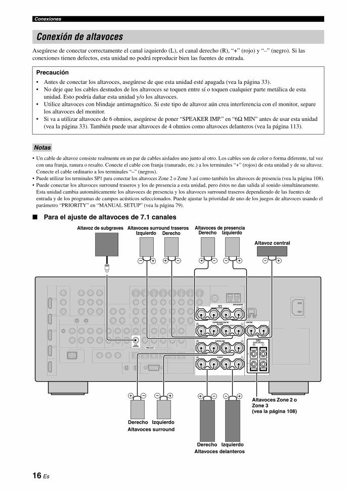
Conexiones
Asegúrese de conectar correctamente el canal izquierdo (L), el canal derecho (R), “+” (rojo) y “–” (negro). Si las conexiones tienen defectos, esta unidad no podrá reproducir bien las fuentes de entrada.
• Un cable de altavoz consiste realmente en un par de cables aislados uno junto al otro. Los cables son de color o forma diferente, tal vez con una franja, ranura o resalto. Conecte el cable con franja (ranurado, etc.) a los terminales “+” (rojos) de esta unidad y de su altavoz. Conecte el cable ordinario a los terminales “–” (negros).
• Puede utilizar los terminales SP1 para conectar los altavoces Zone 2 o Zone 3 así como también los altavoces de presencia (vea la página 108).• Puede conectar los altavoces surround traseros y los de presencia a esta unidad, pero éstos no dan salida al sonido simultáneamente.
Esta unidad cambia automáticamente los altavoces de presencia y los altavoces surround traseros dependiendo de las fuentes de entrada y de los programas de campos acústicos seleccionados. Puede ajustar la prioridad de uno de los juegos de altavoces usando el parámetro “PRIORITY” en “MANUAL SETUP” (vea la página 79).
Para el ajuste de altavoces de 7.1 canales
Conexión de altavoces
Precaución
• Antes de conectar los altavoces, asegúrese de que esta unidad esté apagada (vea la página 33).• No deje que los cables desnudos de los altavoces se toquen entre sí o toquen cualquier parte metálica de esta
unidad. Esto podría dañar esta unidad y/o los altavoces.• Utilice altavoces con blindaje antimagnético. Si este tipo de altavoz aún crea interferencia con el monitor, separe
los altavoces del monitor.• Si va a utilizar altavoces de 6 ohmios, asegúrese de poner “SPEAKER IMP.” en “6Ω MIN” antes de usar esta unidad
(vea la página 33). También puede usar altavoces de 4 ohmios como altavoces delanteros (vea la página 113).
Notas
SPEAKERS
CENTERBI-AMP
SURROUND BACK/
PRESENCE/ZONE 2/ZONE 3SP1
FRONT
SURROUNDZONE 2/ZONE 3
SINGLE
SP2
PRE OUT
SUBWOOFER
+
+ +
R L
R L
+ + +R L
+ +R L
+ +R L
Altavoces delanteros
Altavoces surround
Altavoces de presenciaAltavoz de subgravesDerecho IzquierdoIzquierdo
Altavoz central
Altavoces surround traserosDerecho
Izquierdo
IzquierdoDerecho
Derecho
Altavoces Zone 2 o Zone 3 (vea la página 108)
16 Es

ConexionesP
RE
PAR
AC
IÓN
Esp
año
l
Para el ajuste de altavoces de 6.1 canales
Para el ajuste de altavoces de 5.1 canales
Altavoz surround trasero
SPEAKERS
CENTERBI-AMP
SURROUND BACK/
PRESENCE/ZONE 2/ZONE 3SP1
FRONT
SURROUNDZONE 2/ZONE 3
SINGLE
SP2
PRE OUT
SUBWOOFER
+
+ +
R L
R L
+ + +R L
+ +R L
+ +R L
Altavoces delanteros
Altavoces surround
Altavoces de presencia (vea las páginas 15 y 16)
Altavoz de subgraves
Altavoz central
Izquierdo
IzquierdoDerecho
Derecho
Altavoces Zone 2 o Zone 3 (vea la página 108)
SPEAKERS
CENTERBI-AMP
SURROUND BACK/
PRESENCE/ZONE 2/ZONE 3SP1
FRONT
SURROUNDZONE 2/ZONE 3
SINGLE
SP2
PRE OUT
SUBWOOFER
+
+ +
R L
R L
+ + +R L
+ +R L
+ +R L
Altavoces delanteros
Altavoces surround
Altavoz de subgraves
Altavoz central
Izquierdo
IzquierdoDerecho
Derecho
Altavoces Zone 2 o Zone 3 (vea la página 108)
Altavoces delanteros para conexiones de biamplificación (vea la página 19)
Altavoces de presencia (vea las páginas 15 y 16)
17 Es

Conexiones
Conexión de cables de altavoces
1 Quite aproximadamente 10 mm de aislamiento del extremo de cada cable de altavoz y luego retuerza juntos los hilos expuestos del cable para evitar cortocircuitos.
2 Afloje la perilla con la llave de terminales de altavoces suministrada.
3 Inserte un cable pelado en el agujero de cada terminal.
4 Apriete la perilla para asegurar el cable usando la llave para terminales de altavoces suministrada.
5 Enganche la llave para terminales de altavoces en WRENCH HOLDER del panel trasero de esta unidad cuando no la utilice.
Conexión a los terminales de altavoces SP2
Conecte los altavoces Zone 2 o Zone 3 a estos terminales (vea la página 108).
1 Abra la lengüeta.
2 Inserte un cable pelado en el agujero del terminal.
3 Cierre la lengüeta para asegurar el cable.
10 mm
Llave para terminales de altavoces
Rojo: positivo (+)Negro: negativo (–)
Rojo: positivo (+)Negro: negativo (–)
18 Es
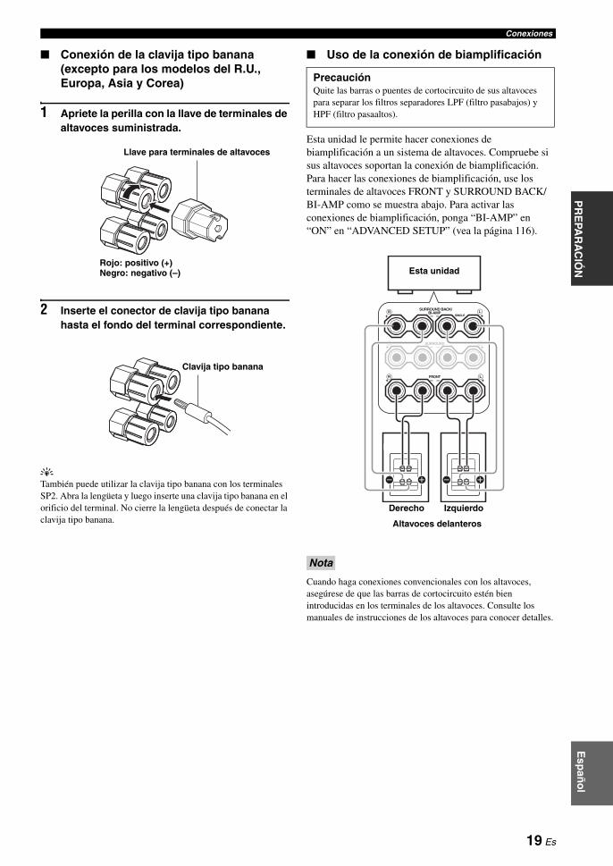
ConexionesP
RE
PAR
AC
IÓN
Esp
año
l
Conexión de la clavija tipo banana (excepto para los modelos del R.U., Europa, Asia y Corea)
1 Apriete la perilla con la llave de terminales de altavoces suministrada.
2 Inserte el conector de clavija tipo banana hasta el fondo del terminal correspondiente.
yTambién puede utilizar la clavija tipo banana con los terminales SP2. Abra la lengüeta y luego inserte una clavija tipo banana en el orificio del terminal. No cierre la lengüeta después de conectar la clavija tipo banana.
Uso de la conexión de biamplificación
Esta unidad le permite hacer conexiones de biamplificación a un sistema de altavoces. Compruebe si sus altavoces soportan la conexión de biamplificación.Para hacer las conexiones de biamplificación, use los terminales de altavoces FRONT y SURROUND BACK/BI-AMP como se muestra abajo. Para activar las conexiones de biamplificación, ponga “BI-AMP” en “ON” en “ADVANCED SETUP” (vea la página 116).
Cuando haga conexiones convencionales con los altavoces, asegúrese de que las barras de cortocircuito estén bien introducidas en los terminales de los altavoces. Consulte los manuales de instrucciones de los altavoces para conocer detalles.
Rojo: positivo (+)Negro: negativo (–)
Llave para terminales de altavoces
Clavija tipo banana
PrecauciónQuite las barras o puentes de cortocircuito de sus altavoces para separar los filtros separadores LPF (filtro pasabajos) y HPF (filtro pasaaltos).
Nota
BI-AMPSURROUND BACK/
FRONT
SINGLE
+ +
++
R L
SURROUND+ +R
R
L
L
Esta unidad
IzquierdoDerecho
Altavoces delanteros
19 Es

Conexiones
Jacks de audioEsta unidad tiene tres tipos de jacks de audio. La conexión depende de la disponibilidad de jacks de audio en sus otros componentes.
Jacks AUDIOPara señales de audio analógico convencional transmitido por cables de audio analógico izquierdo y derecho. Conecte las clavijas rojas a los jacks derechos y las blancas a los izquierdos.
Jacks DIGITAL COAXIALPara señales de audio digital transmitidas por cables de audio digital coaxiales.
DIGITAL OPTICAL Jacks Para señales de audio digital transmitidas por cables de audio digital ópticos.
Puede utilizar los jacks digitales para introducir PCM, Dolby Digital y series de bits DTS. Cuando conecte componentes a los jacks COAXIAL y OPTICAL, tendrán prioridad las señales introducidas por el jack COAXIAL. Todos los jacks de entrada digital son compatibles con señales digitales con muestreo de hasta 96 kHz.
Jacks de vídeoEsta unidad tiene tres tipos de jacks de vídeo. Conecte los jacks de entrada de vídeo de esta unidad a los jacks de salida de vídeo del componente de entrada para cambiar simuláneamente las fuentes de audio y vídeo. La conexión depende de la disponibilidad de jacks de entrada en su monitor de vídeo.
Jacks VIDEOPara señales de vídeo compuesto convencional transmitidas por cables de vídeo compuesto.
Jacks S VIDEOPara señales S-vídeo, separadas en señales de vídeo de luminancia (Y) y crominancia (C) y transmitidas por conductores separados de cables S-vídeo.
Jacks COMPONENT VIDEOPara señales de vídeo componente, separadas en señales de vídeo de luminancia (Y) y crominancia (PB, PR) y transmitidas por conductores separados de cables de vídeo componente.
yEsta unidad dispone de la función de conversión de vídeo. Vea las páginas 23 y 89 para conocer detalles.
Información sobre jacks y clavijas de cables
Nota
COAXIAL
DIGITALAUDIO
OPTICAL
DIGITALRL
CORL
Clavijas izquierda y derecha de
cables de audio analógico
Clavija de cable de
audio digital óptico
Clavija de cable de audio digital
coaxial
Jacks de audio y clavijas de cables
(Rojo)(Blanco) (Anaranjado)
VIDEO S VIDEOCOMPONENT VIDEO
Y R PB P
PBY PRSV
Clavija de cable de
vídeo compuesto
Clavija de cable de S-vídeo
Clavijas de cables de vídeo
componente
Jacks de vídeo y clavijas de cables
(Amarillo) (Verde) (Azul) (Rojo)
20 Es
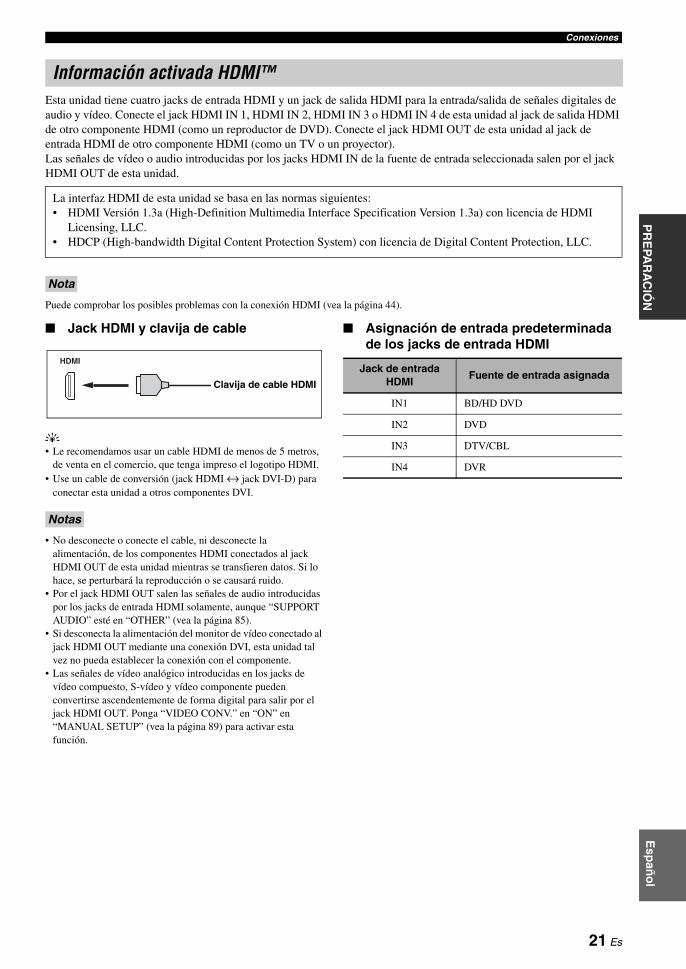
ConexionesP
RE
PAR
AC
IÓN
Esp
año
l
Esta unidad tiene cuatro jacks de entrada HDMI y un jack de salida HDMI para la entrada/salida de señales digitales de audio y vídeo. Conecte el jack HDMI IN 1, HDMI IN 2, HDMI IN 3 o HDMI IN 4 de esta unidad al jack de salida HDMI de otro componente HDMI (como un reproductor de DVD). Conecte el jack HDMI OUT de esta unidad al jack de entrada HDMI de otro componente HDMI (como un TV o un proyector).Las señales de vídeo o audio introducidas por los jacks HDMI IN de la fuente de entrada seleccionada salen por el jack HDMI OUT de esta unidad.
Puede comprobar los posibles problemas con la conexión HDMI (vea la página 44).
Jack HDMI y clavija de cable
y• Le recomendamos usar un cable HDMI de menos de 5 metros,
de venta en el comercio, que tenga impreso el logotipo HDMI.• Use un cable de conversión (jack HDMI ↔ jack DVI-D) para
conectar esta unidad a otros componentes DVI.
• No desconecte o conecte el cable, ni desconecte la alimentación, de los componentes HDMI conectados al jack HDMI OUT de esta unidad mientras se transfieren datos. Si lo hace, se perturbará la reproducción o se causará ruido.
• Por el jack HDMI OUT salen las señales de audio introducidas por los jacks de entrada HDMI solamente, aunque “SUPPORT AUDIO” esté en “OTHER” (vea la página 85).
• Si desconecta la alimentación del monitor de vídeo conectado al jack HDMI OUT mediante una conexión DVI, esta unidad tal vez no pueda establecer la conexión con el componente.
• Las señales de vídeo analógico introducidas en los jacks de vídeo compuesto, S-vídeo y vídeo componente pueden convertirse ascendentemente de forma digital para salir por el jack HDMI OUT. Ponga “VIDEO CONV.” en “ON” en “MANUAL SETUP” (vea la página 89) para activar esta función.
Asignación de entrada predeterminada de los jacks de entrada HDMI
Información activada HDMI™
La interfaz HDMI de esta unidad se basa en las normas siguientes:• HDMI Versión 1.3a (High-Definition Multimedia Interface Specification Version 1.3a) con licencia de HDMI
Licensing, LLC.• HDCP (High-bandwidth Digital Content Protection System) con licencia de Digital Content Protection, LLC.
Nota
Notas
HDMI
Clavija de cable HDMI
Jack de entrada HDMI
Fuente de entrada asignada
IN1 BD/HD DVD
IN2 DVD
IN3 DTV/CBL
IN4 DVR
21 Es
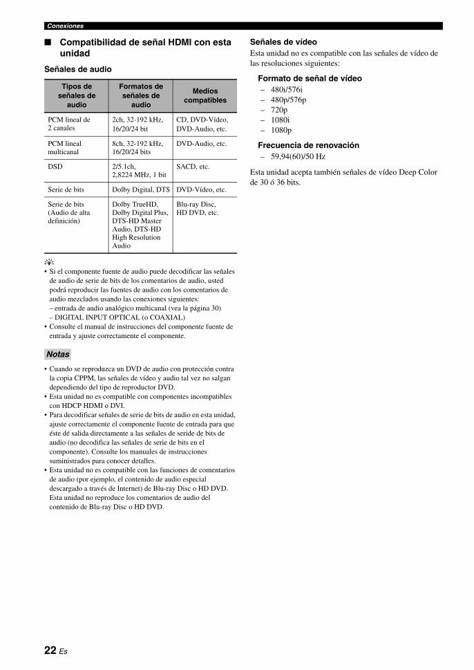
Conexiones
Compatibilidad de señal HDMI con esta unidad
Señales de audio
y• Si el componente fuente de audio puede decodificar las señales
de audio de serie de bits de los comentarios de audio, usted podrá reproducir las fuentes de audio con los comentarios de audio mezclados usando las conexiones siguientes:– entrada de audio analógico multicanal (vea la página 30)– DIGITAL INPUT OPTICAL (o COAXIAL)
• Consulte el manual de instrucciones del componente fuente de entrada y ajuste correctamente el componente.
• Cuando se reproduzca un DVD de audio con protección contra la copia CPPM, las señales de vídeo y audio tal vez no salgan dependiendo del tipo de reproductor DVD.
• Esta unidad no es compatible con componentes incompatibles con HDCP HDMI o DVI.
• Para decodificar señales de serie de bits de audio en esta unidad, ajuste correctamente el componente fuente de entrada para que éste dé salida directamente a las señales de seride de bits de audio (no decodifica las señales de serie de bits en el componente). Consulte los manuales de instrucciones suministrados para conocer detalles.
• Esta unidad no es compatible con las funciones de comentarios de audio (por ejemplo, el contenido de audio especial descargado a través de Internet) de Blu-ray Disc o HD DVD. Esta unidad no reproduce los comentarios de audio del contenido de Blu-ray Disc o HD DVD.
Señales de vídeoEsta unidad no es compatible con las señales de vídeo de las resoluciones siguientes:
Formato de señal de vídeo– 480i/576i– 480p/576p– 720p– 1080i– 1080p
Frecuencia de renovación– 59,94(60)/50 Hz
Esta unidad acepta también señales de vídeo Deep Color de 30 ó 36 bits.
Tipos de señales de
audio
Formatos de señales de
audio
Medios compatibles
PCM lineal de 2 canales
2ch, 32-192 kHz, 16/20/24 bit
CD, DVD-Vídeo, DVD-Audio, etc.
PCM lineal multicanal
8ch, 32-192 kHz, 16/20/24 bits
DVD-Audio, etc.
DSD 2/5.1ch, 2,8224 MHz, 1 bit
SACD, etc.
Serie de bits Dolby Digital, DTS DVD-Vídeo, etc.
Serie de bits (Audio de alta definición)
Dolby TrueHD, Dolby Digital Plus, DTS-HD Master Audio, DTS-HD High Resolution Audio
Blu-ray Disc,HD DVD, etc.
Notas
22 Es
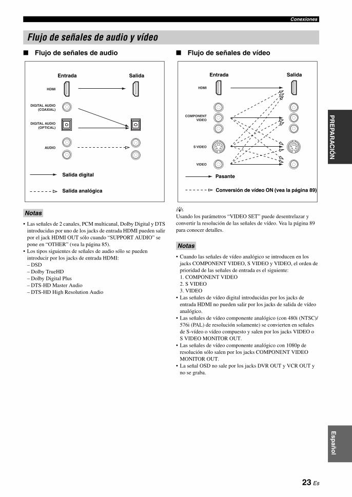
ConexionesP
RE
PAR
AC
IÓN
Esp
año
l
Flujo de señales de audio
• Las señales de 2 canales, PCM multicanal, Dolby Digital y DTS introducidas por uno de los jacks de entrada HDMI pueden salir por el jack HDMI OUT sólo cuando “SUPPORT AUDIO” se pone en “OTHER” (vea la página 85).
• Los tipos siguientes de señales de audio sólo se pueden introducir por los jacks de entrada HDMI:– DSD– Dolby TrueHD– Dolby Digital Plus– DTS-HD Master Audio– DTS-HD High Resolution Audio
Flujo de señales de vídeo
yUsando los parámetros “VIDEO SET” puede desentrelazar y convertir la resolución de las señales de vídeo. Vea la página 89 para conocer detalles.
• Cuando las señales de vídeo analógico se introducen en los jacks COMPONENT VIDEO, S VIDEO y VIDEO, el orden de prioridad de las señales de entrada es el siguiente: 1. COMPONENT VIDEO2. S VIDEO3. VIDEO
• Las señales de vídeo digital introducidas por los jacks de entrada HDMI no pueden salir por los jacks de salida de vídeo analógico.
• Las señales de vídeo componente analógico (con 480i (NTSC)/576i (PAL) de resolución solamente) se convierten en señales de S-vídeo o vídeo compuesto y salen por los jacks VIDEO o S VIDEO MONITOR OUT.
• Las señales de vídeo componente analógico con 1080p de resolución sólo salen por los jacks COMPONENT VIDEO MONITOR OUT.
• La señal OSD no sale por los jacks DVR OUT y VCR OUT y no se graba.
Flujo de señales de audio y vídeo
Notas
DIGITAL AUDIO(OPTICAL)
DIGITAL AUDIO(COAXIAL)
HDMI
AUDIO
SalidaEntrada
Salida analógica
Salida digital
Notas
S VIDEO
VIDEO
COMPONENTVIDEO
HDMI
Pasante
SalidaEntrada
Conversión de vídeo ON (vea la página 89)
23 Es

Conexiones
Conecte su TV (o proyector) al jack HDMI OUT, a los jacks COMPONENT VIDEO MONITOR OUT, al jack S VIDEO MONITOR OUT o al jack VIDEO MONITOR OUT de esta unidad.
yPuede elegir la reproducción de señales de audio HDMI en esta unidad o en otro componente HDMI conectado al jack HDMI OUT del panel trasero de esta unidad. Use el parámetro “SUPPORT AUDIO” en “SOUND MENU” para seleccionar el componente de reproducción de las señales de audio HDMI (vea la página 85).
• Algunos monitores de vídeo conectados a esta unidad mediante una conexión DVI no reconocen las señales de audio/vídeo HDMI que están siendo introducidas si éstos se encuentran en el modo de espera. En este caso, el indicador HDMI parpadea de forma irregular.
• Ponga “VIDEO CONV.” de “OPTION MENU” en “ON” (vea la página 89) para visualizar mensajes cortos y parámetros de campos acústicos.
• El “SET MENU” y los parámetros de campos acústicos aparecen con fondo gris dependiendo del formato de la señal de vídeo introducida y del ajuste de los parámetros en “DISPLAY SET” (vea la página 88).
• Si el monitor de vídeo conectado es compatible con la función de sincronización automática de audio y vídeo (sincronización automática de voz), esta unidad ajustará automáticamente la sincronización de audio y vídeo (vea la página 84). Conecte el monitor de vídeo al jack HDMI OUT de esta unidad y use la función.
Conexión de un proyector o monitor de TV
Asegúrese de que esta unidad y otros componentes estén desenchufados de las tomas de CA.
Notas
VIDEO
S VIDEO
MONITOR OUTVIDEOHDMI COMPONENT VIDEO
MONITOR OUT
Y
PR
PB
OUT
PRPB V SY
TV (o proyector)
Entrada de vídeoEntrada de vídeo componente
Entrada de S-vídeoEntrada HDMI
indica las conexiones recomendadas
indica las conexiones alternativas
24 Es

ConexionesP
RE
PAR
AC
IÓN
Esp
año
l
• Cuando “VIDEO CONV.” se ponga en “OFF” (vea la página 89), asegúrese de hacer el mismo tipo de conexiones de vídeo que las empleadas para su TV (vea la página 24). Por ejemplo, si conecta su TV al jack VIDEO MONITOR OUT de esta unidad, conecte sus otros componentes a los jacks VIDEO.
• Cuando “VIDEO CONV.” se pone en “ON” (vea la página 89), las señales de vídeo convertidas sólo salen por los jacks MONITOR OUT. Cuando grabe una fuente tendrá que hacer los mismos tipos de conexiones de vídeo entre cada componente.
• Para hacer una conexión digital a un componente que no sea el predeterminado y asignado a cada jack DIGITAL INPUT o DIGITAL OUTPUT, seleccione el ajuste correspondiente para “OPTICAL OUT”, “OPTICAL IN” o “COAXIAL IN” en “I/O ASSIGNMENT” (vea la página 86).
• Si conecta su reproductor DVD a los jacks DIGITAL INPUT OPTICAL y DIGITAL INPUT COAXIAL, tendrán prioridad las señales introducidas en el jack DIGITAL INPUT COAXIAL.
• Los mensajes breves no aparecen cuando se introducen señales de vídeo componente con resoluciones de 480p/576p, 720p, 1080i o 1080p.
Conexión de un reproductor Blu-ray Disc o HD DVDConecte su reproductor Blu-ray Disc o HD DVD al jack HDMI IN 1 de esta unidad para realizar completamente las funciones del Blu-ray Disc o HD DVD.
Conexión de otros componentes
Notas
Asegúrese de que esta unidad y otros componentes estén desenchufados de las tomas de CA.
VIDEO
S VIDEO
VIDEOHDMI COMPONENT VIDEO
DIGITAL INPUT
BD/HD DVD
OPTICAL
5
BD/HD DVDBD/HD DVD
Y
PR
PB
BD/HD DVD
A
R
L
IN1
L R OVSPRPBY
Reproductor Blu-ray Disc o HD DVDSalida HDMI
Salida de componente
Salida deS-vídeo
Salida de vídeo
Salida óptica
Salida de audio
indica las conexiones recomendadas
indica las conexiones alternativas
25 Es

Conexiones
Conexión de un reproductor DVD
VIDEO
S VIDEO
VIDEOHDMI COMPONENT VIDEO
DIGITAL INPUT
DVD
COAXIAL
DVD
OPTICAL
62
DVDDVD
Y
PR
PB
DVD
B
R
L
IN2
C OVSL RPRPBY
Reproductor DVDSalida HDMI
Salida coaxial
Salida de componente
Salida deS-vídeo
Salida de vídeo
Salida óptica
Salida de audio
indica las conexiones recomendadas
indica las conexiones alternativas
26 Es

ConexionesP
RE
PAR
AC
IÓN
Esp
año
l
Conexión de una grabadora DVD, PVR o videograbadora
* Cuando conecte otra videograbadora a esta unidad, conéctela a los terminales VCR (jacks S VIDEO IN, VIDEO IN, AUDIO IN, S VIDEO OUT, VIDEO OUT y AUDIO OUT) de igual forma que a los terminales DVR excepto el jack DIGITAL INPUT (COAXIAL).
Conexión de un receptor digital multimedia
Nota
VIDEO
S VIDEO
VIDEOHDMI
DIGITAL INPUT
DVR
COAXIAL
3
VCRDVR OUT OUTININ
DVR
R
L
IN4
DVR OUTIN
RL R LV VS SC
Grabadora DVD, PVR o videograbadora
Salida coaxial
Salida de S-vídeo
Salida de vídeo
Entrada de audio
Entrada de vídeo
Entrada de S
-vídeo
Salida de audio
Salida HD
MI
*
VIDEO
S VIDEO
VIDEOHDMI COMPONENT VIDEO
DIGITAL INPUT
DTV/CBL
OPTICAL
7
DTV/CBLDTV/CBL
Y
PR
PB
DTV/CBL
C
R
L
IN3
OV L RSPRPBY
Receptor de satélite, Receptor de TV por cable
o decodificador HDTVSalida HDMI
Salida de componente
Salida de vídeo
Salida de audio
Salida de S-vídeo
Salida óptica
27 Es

Conexiones
Conexión de componentes de audio
• Conecte su giradiscos al terminal GND de esta unidad para reducir el ruido de la señal. Sin embargo, con algunos giradiscos puede que oiga menos ruido sin la conexión al terminal GND.
• Los jacks PHONO sólo son compatibles con un giradiscos con una cápsula MM o MC de alto rendimiento de salida. Para conectar un giradiscos con un cartucho MC de bajo rendimiento de salida a los jacks PHONO, utilice un transformador elevador en línea o un amplicador para cápsulas MC.
• Cuando conecta ambos jacks, DIGITAL INPUT OPTICAL y DIGITAL INPUT COAXIAL, a un componente de audio tiene prioridad el jack DIGITAL INPUT COAXIAL.
Notas
PHONOGND CD
IN(PLAY) OUT(REC)
CD-R
AUDIODIGITAL INPUT DIGITAL OUTPUT
CD
COAXIAL
CD MD/ TAPECD-R
OPTICAL
9841
TAPEMD/
(REC)(PLAY)IN OUT
R
L
R
L
L RL RL RL R
L
R
L
R
COO
O
Grabadora CD
Giradiscos Reproductor CD Grabadora MD o platina de cinta
Entrada de audio
Entrada ópticaSalida de audio
Salida óptica
Entrada de audio
Salida de audio
Entrada óptica
Tierra
Salida de audio
Salida coaxial
Salida de audio
indica las conexiones recomendadas
indica las conexiones alternativas
28 Es

ConexionesP
RE
PAR
AC
IÓN
Esp
año
l
Conexión de un amplificador externoEsta unidad tiene potencia más que suficiente para cualquier uso en una casa. Sin embargo, si quiere añadir más potencia a la salida de los altavoces o utilizar otro amplificador, conecte un amplificador externo a los jacks PRE OUT.
• Cuando haga conexiones a los jacks PRE OUT, no haga conexiones a los terminales SPEAKERS.• Cada jack PRE OUT da salida a las mismas señales de canales que los terminales SPEAKERS correspondientes.• Ajuste el nivel del sonido del altavoz de subgraves con el control de dicho altavoz.• Algunas señales tal vez no salgan por el SUBWOOFER PRE OUT dependiendo de los ajustes hechos para “SPEAKER SET”
(vea la página 77).• Puede usar la función de ajuste automático aunque utilice un amplificador externo (vea la página 37).
1 Jack CENTER PRE OUTJacks de salida de canal central.
2 Jacks FRONT PRE OUTJacks de salida de canales delanteros.
3 Jacks SURROUND PRE OUTJacks de salida de canales surround.
4 Jacks SUR.BACK/PRESENCE PRE OUTJacks de salida de canales surround traseros o de presencia. Cuando sólo conecte un amplificador externo para los canales surround traseros, conéctelo al jack SINGLE (SB).
y• Ponga “SUR.B L/R SP” en “LRGx2”, “LRGx1”, “SMLx2” o
“SMLx1”, y “PRESENCE SP” en “NONE” (vea la página 78), para dar salida a las señales del canal surround trasero por los jacks SUR.BACK/PRESENCE PRE OUT.
• Ponga “PRESENCE SP” en “YES” y “SUR.B L/R SP” en “NONE” (vea la página 78) para dar salida a las señales del canal de presencia por los jacks SUR.BACK/PRESENCE PRE OUT.
• Cuando “BI-AMP” se pone en “ON” (vea la página 19), esta unidad da salida a las señales de audio del canal delantero por los jacks SUR.BACK/PRESENCE PRE OUT.
5 Jack SUBWOOFER PRE OUTConecte un altavoz de subgraves con amplificador incorporado.
Notas
PRE OUT
SUBWOOFER
CENTER FRONT SURROUND
PRESENCESUR.BACK/
SINGLE(SB)
R
L
5
4321
29 Es
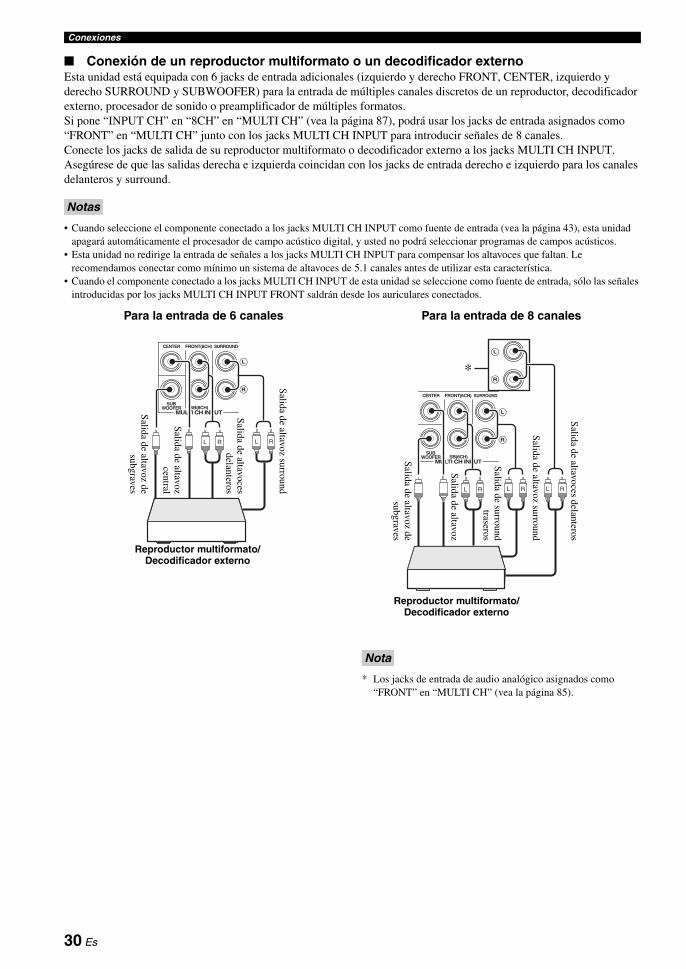
Conexiones
Conexión de un reproductor multiformato o un decodificador externoEsta unidad está equipada con 6 jacks de entrada adicionales (izquierdo y derecho FRONT, CENTER, izquierdo y derecho SURROUND y SUBWOOFER) para la entrada de múltiples canales discretos de un reproductor, decodificador externo, procesador de sonido o preamplificador de múltiples formatos.Si pone “INPUT CH” en “8CH” en “MULTI CH” (vea la página 87), podrá usar los jacks de entrada asignados como “FRONT” en “MULTI CH” junto con los jacks MULTI CH INPUT para introducir señales de 8 canales.Conecte los jacks de salida de su reproductor multiformato o decodificador externo a los jacks MULTI CH INPUT. Asegúrese de que las salidas derecha e izquierda coincidan con los jacks de entrada derecho e izquierdo para los canales delanteros y surround.
• Cuando seleccione el componente conectado a los jacks MULTI CH INPUT como fuente de entrada (vea la página 43), esta unidad apagará automáticamente el procesador de campo acústico digital, y usted no podrá seleccionar programas de campos acústicos.
• Esta unidad no redirige la entrada de señales a los jacks MULTI CH INPUT para compensar los altavoces que faltan. Le recomendamos conectar como mínimo un sistema de altavoces de 5.1 canales antes de utilizar esta característica.
• Cuando el componente conectado a los jacks MULTI CH INPUT de esta unidad se seleccione como fuente de entrada, sólo las señales introducidas por los jacks MULTI CH INPUT FRONT saldrán desde los auriculares conectados.
Para la entrada de 6 canales Para la entrada de 8 canales
* Los jacks de entrada de audio analógico asignados como “FRONT” en “MULTI CH” (vea la página 85).
Notas
MULTI CH INPUT
SUBWOOFER
CENTER FRONT(6CH) SURROUND
SB(8CH)
R
L
L R L R
Salida de altavoz de
subgravesReproductor multiformato/
Decodificador externo
Salida de altavoz
central
Salida de altavoz surround
Salida de altavoces
delanteros
Nota
MULTI CH INPUT
SUBWOOFER
SUB
CENTER FRONT(6CH) SURROUND
SB(8CH)
TAPEMD/
( C)( )
R
L
R
L
L R L RL R
Reproductor multiformato/Decodificador externo
Salida de altavoces delanteros
Salida de altavoz desubgraves
Salida de altavoz
Salida de surroundtraseros
Salida de altavoz surround
*
30 Es
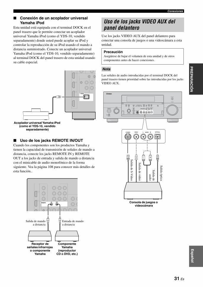
ConexionesP
RE
PAR
AC
IÓN
Esp
año
l
Conexión de un acoplador universal Yamaha iPod
Esta unidad está equipada con el terminal DOCK en el panel trasero que le permite conectar un acoplador universal Yamaha iPod (como el YDS-10, vendido separadamente) donde usted puede acoplar su iPod y controlar la reproducción de su iPod usando el mando a distancia suministrado. Conecte un acoplador universal Yamaha iPod (como el YDS-10, vendido separadamente) al terminal DOCK del panel trasero de esta unidad usando su cable especial.
Uso de los jacks REMOTE IN/OUTCuando los componentes son los productos Yamaha y tienen la capacidad de transmisión de señales de mando a distancia, conecte los jacks REMOTE IN y REMOTE OUT a los jacks de entrada y salida de mando a distancia con el minicable de audio monofónico de la forma siguiente. Vea la página 108 para conocer más detalles de esta función..
Use los jacks VIDEO AUX del panel delantero para conectar una consola de juegos o una videocámara a esta unidad.
Las señales de audio introducidas por el terminal DOCK del panel trasero tienen prioridad sobre las introducidas por los jacks VIDEO AUX.
DOCK
Acoplador universal Yamaha iPod (como el YDS-10, vendido
separadamente)
REMOTE IN OUT
Componente Yamaha
(reproductor CD o DVD, etc.)
Entrada de mando a distancia
Salida de mandoa distancia
Receptor de señales infrarrojas
o componente Yamaha
Uso de los jacks VIDEO AUX del panel delantero
PrecauciónAsegúrese de bajar el volumen de esta unidad y de otros componentes antes de hacer conexiones.
Nota
MASTER
PURE DIRECT
VOLUME
MAIN ZONE
INPUT
OFFON
SLEEP
ZONE ON/OFF ZONE CONTROLS
MULTI ZONE
MICOPTIMIZER
EFFECT
PROGRAM
YPAO
ZONE 3
RL OPTICAL
ZONE 2
AUDIO
VIDEO AUX
SILENT CINEMA S VIDEO VIDEO
PHONES
MODETUNING
PRESET/TUNING
EDIT
FM/AMTUNINGPRESET/
MAN'L/AUTO FMMEMORY
STRAIGHT
CONTROLSELECTAUDIO TONE
A/B/C/D/E
ON/OFF
RL OPTICALAUDIOS VIDEO VIDEO
OVS L R
Consola de juegos o videocámara
Salida de S-V
ídeo
Salida de vídeo
Salida de
audio
Salida óptica
31 Es

Conexiones
Con esta unidad se suministran antenas interiores de FM y AM. Conecte correctamente cada antena a los terminales designados. Generalmente, estas antenas deben proporcionar señales de intensidad suficiente.
• (Modelos de Asia y General solamente) Asegúrese de establecer el paso de frecuencias del sintonizador según la separación de frecuencias de su zona (vea la página 116).
• La antena de cuadro de AM deberá colocarse lejos de esta unidad.
• La antena de cuadro de AM deberá estar siempre conectada, aunque esté conectada una antena AM exterior.
• Una antena exterior bien conectada proporciona una recepción más clara que una interior. Si tiene problemas con la recepción, instale una antena exterior. Consulte al centro de servicio o concesionario Yamaha autorizado acerca de las antena exteriores.
Conexión del cable de alimentación de CAEnchufe el cable de alimentación de CA suministrado en la entrada de CA después de completar todas las demás conexiones, y luego enchúfelo en la toma de CA.
(Modelo de Asia solamente) Antes de conectar esta unidad a una toma de CA, seleccione uno de los cables de alimentación suministrados que sea apropiado para conectarlo a dicha toma de CA.
AC OUTLET(S) (SWITCHED)Modelos del R.U. y Australia ................................ 1 salidaModelo de Corea...................................................NingunoOtros modelos ....................................................... 2 salidas
Use estas tomas para suministrar alimentación a cualquier componente conectado. Conecte los cables de alimentación de sus otros componentes a estas tomas. La alimentación a estas tomas se suministra cuando se enciende esta unidad. Sin embargo, la alimentación a estas tomas se corta cuando se apaga esta unidad. Para información sobre el consumo máximo o total del componente que puede conectarse a estas tomas, vea “Especificaciones” en la página 131.
Conexión de antenas de FM y AM
Notas
ANTENNA
FM GND AM75Ω UNBAL.
Antena de FMinterior
(suministrada)
Tierra (terminal GND)Para tener la máxima seguridad y mínima interferencia, conecte el terminal de antena GND a una buena conexión a tierra. Una buena conexión a tierra es una varilla metálica clavada en tierra húmeda.
Antena de cuadro de AM (suministrada)
Antena de AM exteriorUtilice un cable cubierto de vinilo de 5 a 10 m extendido hacia el exterior desde una ventana.
Conexión del cable de alimentación
Nota
Apoyo a la memoriaEl circuito de apoyo a la memoria impide que se pierdan los datos guardados aunque esta unidad esté en el modo de espera. Sin embargo, los datos guardados se perderán si se desconecta el cable de alimentación de la toma de CA o si el suministro eléctrico se corta durante más de una semana.
AC OUTLETS
AC IN
A la toma de CA
32 Es

ConexionesP
RE
PAR
AC
IÓN
Esp
año
l
1 Asegúrese de que esta unidad esté apagada.
2 Mantenga pulsado OSTRAIGHT en el panel delantero y luego pulse AMASTER ON/OFF hasta la posición ON para encender esta unidad.Esta unidad se enciende y el menú de ajuste avanzado aparece en el visualizador del panel delantero.
3 Gire el selector NPROGRAM para seleccionar “SPEAKER IMP.”.
4 Pulse repetidamente OSTRAIGHT para seleccionar “6Ω MIN”.
5 Pulse AMASTER ON/OFF para soltarlo hasta la posición OFF para guardar el nuevo ajuste y apague esta unidad.
Los ajustes que usted hace se activan la próxima vez que enciende esta unidad.
Encendido de esta unidad
Pulse AMASTER ON/OFF en el panel delantero hasta la posición ON para encender esta unidad.Cuando enciende esta unidad pulsando AMASTER ON/OFF también se enciende la zona principal.
yCuando encienda esta unidad habrá un retardo de unos pocos segundos hasta que esta unidad pueda reproducir sonidos.
Apagado de esta unidad
Pulse de nuevo AMASTER ON/OFF en el panel delantero para soltarlo hasta la posición OFF y apagar esta unidad.
• BMAIN ZONE ON/OFF en el panel delantero, así como también 8POWER y 7STANDBY en el mando a distancia, sólo funcionan cuando se pulsa AMASTER ON/OFF hasta la posición ON.
• Fundamenalment, le recomendamos usar el modo de espera para apagar esta unidad.
Ponga la zona principal en el modo de espera
Pulse BMAIN ZONE ON/OFF (o 7STANDBY) para poner la zona principal en el modo de espera.En el modo de espera, esta unidad consume un poco de energía para recibir señales infrarrojas del mando a distancia.
Encendido de la zona principal desde el modo de espera
Pulse BMAIN ZONE ON/OFF (o 8POWER) para encender la zona principal.
y• Cuando encienda esta unidad habrá un retardo de unos pocos
segundos hasta que esta unidad pueda reproducir sonidos.• Estos botones sólo funcionan cuando se pulsa AMASTER
ON/OFF hasta la posición ON.
Ajuste de la impedancia de los altavoces
PrecauciónSi va a utilizar altavoces de 6 ohmios, ponga “SPEAKER IMP.” en “6Ω MIN” como sigue ANTES de usar esta unidad. También puede usar altavoces de 4 ohmios como altavoces delanteros.
Nota
EFFECT
STRAIGHT
MASTER
Mientras lo mantiene pulsado
Encendido y apagado de esta unidad
Notas
Si hay algún problema...• Apague primero esta unidad y vuelva a encenderla.• Si el problema persiste, inicialice los parámetros de
esta unidad. Vea la página 124 para conocer detalles.
33 Es
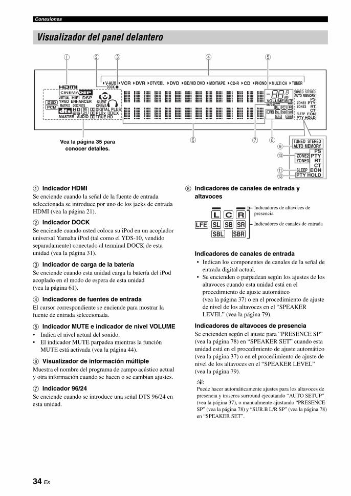
Conexiones
1 Indicador HDMISe enciende cuando la señal de la fuente de entrada seleccionada se introduce por uno de los jacks de entrada HDMI (vea la página 21).
2 Indicador DOCKSe enciende cuando usted coloca su iPod en un acoplador universal Yamaha iPod (tal como el YDS-10, vendido separadamente) conectado al terminal DOCK de esta unidad (vea la página 31).
3 Indicador de carga de la bateríaSe enciende cuando esta unidad carga la batería del iPod acoplado en el modo de espera de esta unidad (vea la página 61).
4 Indicadores de fuentes de entradaEl cursor correspondiente se enciende para mostrar la fuente de entrada seleccionada.
5 Indicador MUTE e indicador de nivel VOLUME• Indica el nivel actual del sonido.• El indicador MUTE parpadea mientras la función
MUTE está activada (vea la página 44).
6 Visualizador de información múltipleMuestra el nombre del programa de campo acústico actual y otra información cuando se hacen o se cambian ajustes.
7 Indicador 96/24Se enciende cuando se introduce una señal DTS 96/24 en esta unidad.
8 Indicadores de canales de entrada y altavoces
Indicadores de canales de entrada• Indican los componentes de canales de la señal de
entrada digital actual.• Se encienden o parpadean según los ajustes de los
altavoces cuando esta unidad está en el procedimiento de ajuste automático (vea la página 37) o en el procedimiento de ajuste de nivel de los altavoces en el “SPEAKER LEVEL” (vea la página 79).
Indicadores de altavoces de presenciaSe encienden según el ajuste para “PRESENCE SP” (vea la página 78) en “SPEAKER SET” cuando esta unidad está en el procedimiento de ajuste automático (vea la página 37) o en el procedimiento de ajuste de nivel de los altavoces en el “SPEAKER LEVEL” (vea la página 79).
yPuede hacer automáticamente ajustes para los altavoces de presencia y traseros surround ejecutando “AUTO SETUP” (vea la página 37), o manualmente ajustando “PRESENCE SP” (vea la página 78) y “SUR.B L/R SP” (vea la página 78) en “SPEAKER SET”.
Visualizador del panel delantero
MUTEVOLUMEdB
LL C RSL SB SR
DSDPCM
96/24
TUNED STEREOAUTO MEMORY
PSZONE2ZONE3
SLEEPPTY HOLD
PTYRTCT
EON
CD-R CD PHONO MULTI CH TUNERMD/TAPEBD/HD DVDDVDDOCK
DVR DTV/CBLVCRV-AUX
MASTER AUDIO
MATRIX DISCRETESILENT
CINEMAYPAO ENHANCERVIRTUAL HiFi DSP
HD 9624
q DIGITAL PLUS
q TRUE HDq EXq PL x LFE
SBRSBL
TUNED STEREOAUTO MEMORY
PSZONE2ZONE3
SLEEPPTY HOLD
PTYRTCT
EONBA
0
9876
5431 2
Vea la página 35 para conocer detalles.
Indicadores de altavoces de presencia
Indicadores de canales de entrada
LL C RSL SB SRLFE
SBRSBL
34 Es

ConexionesP
RE
PAR
AC
IÓN
Esp
año
l
9 Indicadores de sintonizadorSe enciende cuando esta unidad está en el modo de sintonización de FM o AM.
Indicador TUNEDSe enciende cuando está unidad sintoniza una emisora (vea la página 54).
Indicador STEREOSe enciende cuando esta unidad recibe una señal intensa de una emisión estéreo por FM mientras el indicador AUTO está encendido (vea la página 54).
Indicador AUTOSe enciende cuando esta unidad está en el modo de sintonización automática (vea la página 54).
Indicador MEMORYParpadea para mostrar que puede guardarse una emisora (vea la página 55).
0 Indicadores ZONE2/ZONE3Se enciende cuando está encendido Zone 2 o Zone 3 (vea la página 109).
A Indicador SLEEPSe enciende mientras el temporizador para dormir está encendido (vea la página 45).
B Indicadores del sistema de datos de radio(Modelo de Europa solamente)
PTY HOLDSe enciende mientras se buscan emisoras del sistema de datos de radio en el modo PTY SEEK.
PS, PTY, RT y CTSe encienden según el modo de visualización del sistema de datos de radio seleccionado.
EONSe enciende cuando el servicio de datos EON está siendo recibido.
C Indicador YPAOSe enciende cuando se ejecuta “AUTO SETUP” y cuando los ajustes de altavoces establecidos en “AUTO SETUP” se utilizan sin ninguna modificación (vea la página 37).
D Indicadores de señal de entradaSe enciende cuando esta unidad reproduce señales de audio digital DSD (Direct Stream Digital) o PCM (modulación por codificación de impulsos).
E Indicadores DSPEl indicador respectivo se enciende cuando se selecciona cualquier programa de campo acústico.
Indicador CINEMA DSPSe enciende cuando usted selecciona un programa de campo acústico CINEMA DSP (vea la página 46).
Indicador HiFi DSPSe enciende cuando usted selecciona un programa de campo acústico HiFi DSP (vea la página 46).
Indicador VIRTUALSe enciende cuando está activo Virtual CINEMA DSP (vea la página 51).
F Indicadores de campo acústicoSe encienden para indicar los campos acústicos activos (vea la página 46).
G Indicador ENHANCERSe enciende cuando está activado el modo Compressed Music Enhancer (vea la página 50).
H Indicador de auricularesSe enciende cuando se conectan auriculares (vea la página 43).
I Indicador SILENT CINEMASe enciende cuando se conectan los auriculares y se selecciona un programa de campo acústico (vea la página 51).
J Indicadores de decodificadorEl indicador respectivo se enciende cuando funciona cualquier decodificador de esta unidad.
DSDPCM
MASTER AUDIO
MATRIX DISCRETE
SILENT CINEMA
YPAO ENHANCER
HD 9624
q DIGITAL PLUS
q TRUE HDq EXq PL x
VIRTUAL HiFi DSPC
D
EFGHI
J
35 Es
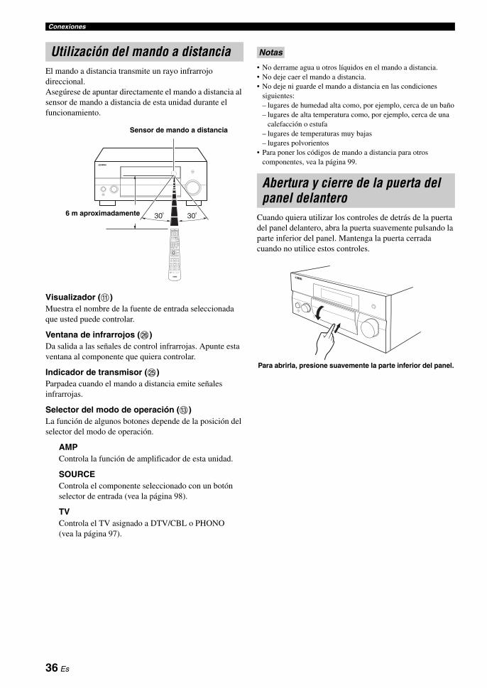
Conexiones
El mando a distancia transmite un rayo infrarrojo direccional.Asegúrese de apuntar directamente el mando a distancia al sensor de mando a distancia de esta unidad durante el funcionamiento.
Visualizador (A)Muestra el nombre de la fuente de entrada seleccionada que usted puede controlar.
Ventana de infrarrojos (P)Da salida a las señales de control infrarrojas. Apunte esta ventana al componente que quiera controlar.
Indicador de transmisor (O)Parpadea cuando el mando a distancia emite señales infrarrojas.
Selector del modo de operación (C)La función de algunos botones depende de la posición del selector del modo de operación.
AMPControla la función de amplificador de esta unidad.
SOURCEControla el componente seleccionado con un botón selector de entrada (vea la página 98).
TVControla el TV asignado a DTV/CBL o PHONO (vea la página 97).
• No derrame agua u otros líquidos en el mando a distancia.• No deje caer el mando a distancia.• No deje ni guarde el mando a distancia en las condiciones
siguientes:– lugares de humedad alta como, por ejemplo, cerca de un baño– lugares de alta temperatura como, por ejemplo, cerca de una
calefacción o estufa– lugares de temperaturas muy bajas– lugares polvorientos
• Para poner los códigos de mando a distancia para otros componentes, vea la página 99.
Cuando quiera utilizar los controles de detrás de la puerta del panel delantero, abra la puerta suavemente pulsando la parte inferior del panel. Mantenga la puerta cerrada cuando no utilice estos controles.
Utilización del mando a distancia
30 306 m aproximadamente
Sensor de mando a distancia
Notas
Abertura y cierre de la puerta del panel delantero
Para abrirla, presione suavemente la parte inferior del panel.
36 Es

PR
EPA
RA
CIÓ
NE
spañ
ol
Esta unidad emplea la tecnología YPAO (Yamaha Parametric Room Acoustic Optimizer) para evitar tener que realizar el molesto ajuste de los altavoces basándose en la escucha del sonido y para poder hacer automáticamente unos ajustes del sonido muy precisos. El micrófono optimizador suministrado capta y esta unidad analiza el sonido que producen sus altavoces en el ambiente de escucha actual.
• Tenga en cuenta que es normal que salgan tonos de prueba altos durante el procedimiento “AUTO SETUP”.
• Para obtener los mejores resultados, asegúrese de que la habitación esté lo más silenciosa podible durante el “AUTO SETUP”. Si hay demasiado ruido ambiental, los resultados puede que no sean satisfactorios.
• Le recomendamos salir de la habitación mientras esta unidad realiza el ajuste automático. Salga de la habitación sin hacer ruido. Esta unidad tarda aproximadamente 3 minutos en completar el ajuste automático.
y• El ajuste inicial para cada parámetro se indica en negrita.• Antes de hacer operaciones, ponga el selector del modo de
operación del mando a distancia en CAMP.
Procedimiento básico para el ajuste automático
1 Asegúrese de que se cumplen los puntos siguientes antes de iniciar las operaciones AUTO SETUP. Los altavoces están bien conectados. Los auriculares están desconectados de esta unidad. Esta unidad y el monitor de vídeo se encienden. El altavoz de subgraves conectado se enciende y
el nivel del volumen se fija en la mitad aproximadamente (o un poco menos).
Los controles de la frecuencia de cruce del altavoz de subgraves se ajustan al máximo.
Si usa los amplificadores externos (vea la página 29), éstos se encenderán y sus ajustes serán apropiados.
La habitación está lo suficientemente silenciosa.
2 Conecte el micrófono optimizador suministrado al jack OPTIMIZER MIC del panel delantero.“MIC ON” y “View OSD Menu” aparece en el visualizador del panel delantero.
La pantalla de menú siguiente aparece en el monitor de vídeo.
yTambién puede ejecutar “AUTO SETUP” usando el menú del sistema que aparece en el visualizador del panel delantero. Cuando conecte el micrófono optimizador al jack OPTIMIZER MIC, en el visualizador del panel delantero aparecerá la visualización siguiente. Este manual usa las ilustraciones de la OSD para explicar el procedimiento “AUTO SETUP”.
3 Ponga el micrófono optimizador en su posición de escucha normal en una superficie nivelada y plana, con la cabeza de micrófono omnidireccional hacia arriba.
ySe le recomienda utilizar un trípode (etc.) para fijar el micrófono optimizador a la misma altura que sus oídos cuando se sienta en la posición de escucha. Puede usar el tornillo colocado en un trípode (etc.) para fijar el micrófono optimizador al trípode (etc.).
Optimización de los ajustes de los altavoces para su habitación de escucha
Utilización AUTO SETUP
Notas
SLEEP
ZONE ON/OFF ZONE CONTROLS
MULTI ZONE
MICOPTIMIZER
EFFECT
PROGRAM
YPAO
ZONE 3
RL OPTICAL
ZONE 2
AUDIO
VIDEO AUX
SILENT CINEMA S VIDEO VIDEO
PHONES
MODETUNING
PRESET/TUNING
EDIT
FM/AMTUNINGPRESET/
MAN'L/AUTO FMMEMORY
STRAIGHT
CONTROLSELECTAUDIO TONE
A/B/C/D/E
Micrófono omnidireccional
[]/[]:[ENTER]:
[ p
AUTO SETUP
SETUP;;;;;;;;;AUTOWIRING;;;;;;;CHECKDISTANCE;;;;;CHECKSIZE;;;;;;;;;CHECKEQ;;;;;;;;;NATURALLEVEL;;;;;;;;CHECKSTART
UP/DOWNStart
.
A U T O S E T U P
E N T E R T O S T A R T
Micrófono optimizador
37 Es

Optimización de los ajustes de los altavoces para su habitación de escucha
4 Pulse 3ENTER para empezar el procedimiento de ajuste.Esta unidad inicia el procedimiento de ajuste automático. Durante el procedimiento de ajuste automático salen sonidos de prueba altos de cada altavoz. Una vez establecidos todos los elementos, el resultado se visualiza en la OSD.
• No haga ninguna operación en esta unidad durante el procedimiento de ajuste automático. Si hace una operación mientras esta unidad está en el procedimiento de ajuste automático, “E-9:USER CANCEL” aparece en la OSD. En tales casos, seleccione “RETRY” para reiniciar el procedimiento de ajuste automático.
• Le recomendamos salir de la habitación mientras esta unidad realiza el ajuste automático. Salga de la habitación sin hacer ruido. Esta unidad tarda aproximadamente 3 minutos en completar el ajuste automático.
La visualización cambia de la forma siguiente.
Los resultados visualizados en la pantalla “RESULT” son los siguientes.
Número de altavoces SP
Visualiza el número de altavoces conectado a esta unidad en el orden siguiente:Delanteros/Traseros/Subgraves
Distancia de altavoces DIST
Visualiza la distancia a los altavoces desde la posición de escucha en el orden siguiente:Distancia del altavoz más cercano/Distancia del altavoz más alejado
Nivel de altavoces LVL
Visualiza el nivel de salida de los altavoces en el orden siguiente:Nivel de salida más bajo/Nivel de salida más alto de los altavoces
• Si “E-10:INTERNAL ERROR” aparece durante el procedimiento de prueba, reinicie desde el paso 2.
• Si ocurre un error durante el procedimiento de ajuste automático, el procedimiento de ajuste se cancelará y aparecerá una pantalla de error. Para conocer detalles, vea “Si aparece una pantalla de error” en la página 41.
• Cuando esta unidad detecta posibles problemas durante el procedimiento de ajuste automático, “WARNING” y el número de los mensajes de aviso aparecen encima de “RESULT” (vea la página 41).
• Dependiendo del ambiente de escucha, “SWFR PHASE:REV” aparece durante el procedimiento de ajuste automático y “SUBWOOFER PHASE” en “SOUND MENU” (vea la página 79) se pone automáticamente en “REVERSE”.
5 Pulse 3ENTER para visualizar detalladamente los resultados del ajuste.
Notas
[ ] :[
AUTO SETUP
INITIALIZINGPRE CHECKMAIN CHECKEQUALIZINGLEVEL
||||||||;;;;;;;;;;EXIT
.
[]/[]:[ENTER]:
[ p
AUTO SETUP
SETUP;;;;;;;;;AUTOWIRING;;;;;;;CHECKDISTANCE;;;;;CHECKSIZE;;;;;;;;;CHECKEQ;;;;;;;;;NATURALLEVEL;;;;;;;;CHECKSTART
UP/DOWNStart
.
[]/[]:[ENTER]:
[ p
AUTO SETUP
RESULTSP : 5/4/0.1DIST: 3.60/4.30mLVL : -10.0/+5.0dB>SET CANCEL
UP/DOWNDetail
.
Notas
[]/[]:[ENTER]:
[ p
AUTO SETUP
RESULTSP : 5/4/0.1DIST: 3.60/4.30mLVL : -10.0/+5.0dB>SET CANCEL
UP/DOWNDetail
.
[p]/[[]:[ENTER]:
RESULT WIRING
FRONT L;;;;;OK
SelectReturn
38 Es
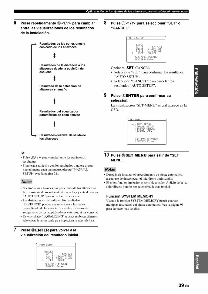
Optimización de los ajustes de los altavoces para su habitación de escuchaP
RE
PAR
AC
IÓN
Esp
año
l
6 Pulse repetidamente 3l / h para cambiar entre las visualizaciones de los resultados de la instalación.
y• Pulse 3k / n para cambiar entre los parámetros
resultantes.• Si no está satisfecho con los resultados o quiere ajustar
manualmente cada parámetro, ejecute “MANUAL SETUP” (vea la página 72).
• Si cambia los altavoces, las posiciones de los altavoces o la disposición de su ambiente de escucha, ejecute de nuevo “AUTO SETUP” para recalibrar su sistema.
• Las distancias visualizadas en los resultados “DISTANCE” pueden ser superiores a las reales dependiendo de las características de su altavoz de subgraves o de los amplificadores externos, si los conecta.
• En los resultados “EQUALIZING” se puede establecer diferentes valores para la misma banda para proporcionar ajustes más finos.
7 Pulse 3ENTER para volver a la visualización del resultado inicial.
8 Pulse 3l / h para seleccionar “SET” o “CANCEL”.
Opciones: SET, CANCEL• Seleccione “SET” para confirmar los resultados
“AUTO SETUP”.• Seleccione “CANCEL” para cancelar los
resultados “AUTO SETUP”.
9 Pulse 3ENTER para confirmar su selección.La visualización “SET MENU” inicial aparece en la OSD.
10 Pulse FSET MENU para salir de “SET MENU”.
• Después de finalizar el procedimiento de ajuste automático, asegúrese de desconectar el micrófono optimizador.
• El micrófono optimizador es sensible al calor. Aléjelo de la luz solar directa y no lo ponga encima de esta unidad.
Notas
Resultados de las conexiones y cableado de los altavoces
Resultados de la distancia a los altavoces desde la posición de escucha
Resultado de la detección de altavoces y tamaño
Resultados del ecualizador paramétrico de cada altavoz
Resultados del nivel de salida de los altavoces
[]/[]:[ENTER]:
[ p
AUTO SETUP
RESULTSP : 5/4/0.1DIST: 3.60/4.30mLVL : -10.0/+5.0dB>SET CANCEL
UP/DOWNEnter
.
Notas
Función SYSTEM MEMORYUsando la función SYSTEM MEMORY puede guardar múltiples resultados del ajuste automático. Vea la página 93 para conocer más detalles.
[]/[]:[ENTER]:
[ p
AUTO SETUP
RESULTSP : 5/4/0.1DIST: 3.60/4.30mLVL : -10.0/+5.0dB>SET CANCEL
UP/DOWNEnter
.
[]/[]:[ENTER]:
[ p
SET MENU
;AUTO SETUP;MANUAL SETUP;SYSTEM MEMORY;SIGNAL INFO
UP/DOWNEnter
.
39 Es

Optimización de los ajustes de los altavoces para su habitación de escucha
Personalización de las mediciones Puede seleccionar el tipo de ecualizador paramétrico, y activar o desactivar cada elemento de verificación.
1 Conecte el micrófono optimizador suministrado a esta unidad y colóquelo adecuadamente.Consulte los pasos 1 a 3 de “Procedimiento básico para el ajuste automático” en la página 37.
2 Pulse repetidamente 3k para seleccionar “SETUP” y luego pulse 3l / h para seleccionar el ajuste deseado.
Opciones: AUTO, RELOAD• Seleccione “AUTO” para ejecutar
automáticamente todo el procedimiento “AUTO SETUP”.
• Seleccione “RELOAD” para restaurar los últimos ajustes “AUTO SETUP” y anular los actuales. Cuando seleccione “RELOAD”, el ajuste automático anterior aparecerá en la OSD. Vea el paso 4 en la página 38 y realice las operaciones.
• “RELOAD” sólo se encuentra disponible si usted ha ejecutado previamente “AUTO SETUP” y ha confirmado los resultados.
• Si seleccionó “RELOAD” en el paso 2 no salen tonos de prueba y el resultado del ajuste automático anterior aparece en la OSD.
3 Pulse repetidamente 3k / n para seleccionar “WIRING”, “DISTANCE”, “SIZE”, “EQ” o “LEVEL” y luego pulse 3l / h para seleccionar el ajuste deseado.Esta unidad realiza las comprobaciones siguientes:
Cableado de altavoces WIRING
Comprueba qué altavoces están conectados y la polaridad de cada altavoz.
Distancia de altavoces DISTANCEComprueba la distancia a cada altavoz desde la posición de escucha y ajusta la sincronización de cada canal.
Tamaño de altavoz SIZEComprueba la respuesta de frecuencia de cada altavoz y ajusta la frecuencia baja de transición apropiada para cada canal.
Opciones: CHECK, SKIP• Seleccione “CHECK” para ajustar y comprobar
automáticamente el elemento.• Seleccione “SKIP” para omitir el elemento y no
realizar ajustes.
Tipo de ecualizador paramétrico EQEl ecualizador paramétrico ajusta el nivel de las bandas de frecuencias especificadas. Esta unidad selecciona automáticamente las bandas de frecuencias cruciales para la habitación de escucha y ajusta el nivel de las bandas de frecuencias seleccionadas para crear un campo acústico uniforme en la habitación. Puede seleccionar el tipo de ajustes del ecualizador paramétrico de entre las opciones siguientes.Opciones: NATURAL, FLAT, FRONT, SKIP• Seleccione “NATURAL” para que la media de la
respuesta de frecuencia de todos los altavoces con las frecuencias más altas tenga menos énfasis. Se recomienda si el ajuste FLAT suena un poco discordante.
• Seleccione “FLAT” para calcular el promedio de la respuesta de frecuencia de todos los altavoces. Recomendado si todos sus altavoces son de una calidad similar.
• Seleccione “FRONT” para ajustar la respuesta de frecuencia de cada altavoz según el sonido de sus altavoces delanteros. Se recomienda si sus altavoces delanteros son de una calidad mucho más alta que la de los otros altavoces.
• Seleccione “SKIP” para omitir este elemento y no realizar ajustes.
Nivel de sonido LEVELComprueba y ajusta el nivel del sonido de cada altavoz.Opciones: CHECK, SKIP• Seleccione “CHECK” para ajustar y comprobar
automáticamente este elemento.• Seleccione “SKIP” para omitir este elemento y no
realizar ajustes.
4 Después de establecer la medición, inicie el procedimiento de ajuste automático.Consulte los pasos 4 a 6 de “Procedimiento básico para el ajuste automático” en la página 38 para conocer detalles.
Notas
Función SYSTEM MEMORYUsando la función SYSTEM MEMORY puede guardar múltiples resultados del ajuste automático. Vea la página 93 para conocer más detalles.
40 Es

Optimización de los ajustes de los altavoces para su habitación de escuchaP
RE
PAR
AC
IÓN
Esp
año
l
Si aparece una pantalla de error
Pulse 3l / h para seleccionar “RETRY” o “EXIT” y luego pulse 3ENTER.La visualización siguiente es un ejemplo en el que “E-9:USER CANCEL” aparece en la OSD.
Opciones: RETRY, EXIT• Seleccione “RETRY” para reintentar el procedimiento
“AUTO SETUP”.• Seleccione “EXIT” para salir del procedimiento
“AUTO SETUP”.
y• Si aparece “E-5:NOISY” en la OSD, usted también podrá
seleccionar “PROCEED” y dejar que esta unidad continúe con el ajuste automático. Sin embargo, para hacer un ajuste más preciso, le recomendamos realizar de nuevo el procedimiento de ajuste automático.
• Si “E-10:INTERNAL ERROR” aparece en la OSD, sólo podrá seleccionar “EXIT”.
• Para conocer detalles de cada mensaje de error, consulte la sección “AUTO SETUP” de “Solución de problemas” en la página 123.
Si aparece “WARNING”Cuando esta unidad detecta posibles problemas durante el procedimiento de ajuste automático, “WARNING” aparece en la visualización de resultados. Verifique los mensajes de aviso para corregir los ajustes de los altavoces.
Las advertencias, a diferencia de los errores, no cancelan el procedimiento “AUTO SETUP”.
1 Asegúrese de que el puntero apunte a “WARNING” y luego pulse 3ENTER para visualizar la información detallada relacionada con la advertencia.El número a la derecha de “WARNING” indica el número de mensajes de aviso.
2 Pulse repetidamente 3l / h para cambiar entre las visualizaciones de advertencia.
y• Para conocer detalles de cada mensaje de advertencia,
consulte la sección “AUTO SETUP” de “Solución de problemas” en la en la página 123.
• Cuando el mensaje de advertencia correspondiente no se aplica al altavoz se visualiza “– – –”.
• Si el ajuste del nivel del sonido del altavoz de subgraves conectado está demasiado alto o bajo, “TOO LOUD” (nivel del sonido demasiado alto) o “TOO LOW” (nivel del sonido demasaido bajo) se visualiza en el visualizador “W-3:LEVEL ERROR”. Ajuste correctamente el nivel del sonido del altavoz de subgraves conectado.
3 Pulse 3ENTER para volver a la visualización del resultado inicial.
yEl ajuste se hace aunque aparezca “WARNING”, sin embargo, el ajuste no será óptimo.
Nota
[p]/[[]:[ENTER]:
ERROR
E-9:USER CANCELDon't operateany function
>RETRY EXIT
SelectEnter
.
[p]/[[]:[ENTER]:
ERROR
E-5:NOISYKeep silent
>RETRY EXIT PROCEED
SelectEnter
.
[]/[]:[ENTER]:
[ p
AUTO SETUP
WARNING 2RESULTSP : 5/4/0.1DIST: 3.60/4.30mLVL : -10.0/+5.0dB>SET CANCEL
UP/DOWNDetail
.
[p]/[[]:[ENTER]:
WARNING
W-1:OUT OF PHASEReverse channel
FL ---CENTER--- PRSL ---SBL ---
SelectReturn
[p]/[[]:[ENTER]:
WARNING
W-3:LEVEL ERROR--- FRCENTERPL ------ SR--- SBLSWFR:TOO LOUD
SelectReturn
41 Es
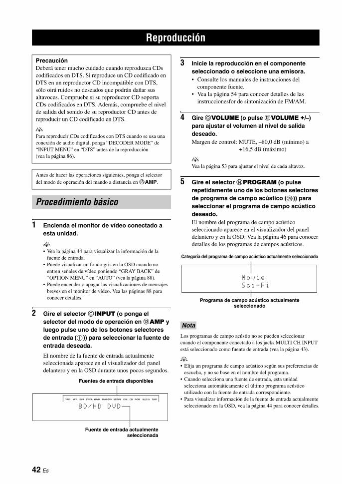
1 Encienda el monitor de vídeo conectado a esta unidad.
y• Vea la página 44 para visualizar la información de la
fuente de entrada.• Puede visualizar un fondo gris en la OSD cuando no
entren señales de vídeo poniendo “GRAY BACK” de “OPTION MENU” en “AUTO” (vea la página 88).
• Puede encender o apagar las visualizaciones de mensajes breves en el monitor de vídeo. Vea las páginas 88 para conocer detalles.
2 Gire el selector CINPUT (o ponga el selector del modo de operación en CAMP y luego pulse uno de los botones selectores de entrada (1)) para seleccionar la fuente de entrada deseada.
El nombre de la fuente de entrada actualmente seleccionada aparece en el visualizador del panel delantero y en la OSD durante unos pocos segundos.
3 Inicie la reproducción en el componente seleccionado o seleccione una emisora.• Consulte los manuales de instrucciones del
componente fuente.• Vea la página 54 para conocer detalles de las
instruccionesfor de sintonización de FM/AM.
4 Gire QVOLUME (o pulse BVOLUME +/–) para ajustar el volumen al nivel de salida deseado.Margen de control: MUTE, –80,0 dB (mínimo) a
+16,5 dB (máximo)
yVea la página 53 para ajustar el nivel de cada altavoz.
5 Gire el selector NPROGRAM (o pulse repetidamente uno de los botones selectores de programa de campo acústico (N)) para seleccionar el programa de campo acústico deseado.El nombre del programa de campo acústico seleccionado aparece en el visualizador del panel delantero y en la OSD. Vea la página 46 para conocer detalles de los programas de campos acústicos.
Los programas de campo acústio no se pueden seleccionar cuando el componente conectado a los jacks MULTI CH INPUT está seleccionado como fuente de entrada (vea la página 43).
y• Elija un programa de campo acústico según sus preferencias de
escucha, y no se base en el nombre del programa.• Cuando selecciona una fuente de entrada, esta unidad
selecciona automáticamente el último programa acústico utilizado con la fuente de entrada correspondiente.
• Para visualizar información de la fuente de entrada actualmente seleccionado en la OSD, vea la página 44 para conocer detalles.
Reproducción
PrecauciónDeberá tener mucho cuidado cuando reproduzca CDs codificados en DTS. Si reproduce un CD codificado en DTS en un reproductor CD incompatible con DTS, sólo oirá ruidos no deseados que podrán dañar sus altavoces. Compruebe si su reproductor CD soporta CDs codificados en DTS. Además, compruebe el nivel de salida del sonido de su reproductor CD antes de reproducir un CD codificado en DTS.
yPara reproducir CDs codificados con DTS cuando se usa una conexión de audio digital, ponga “DECODER MODE” de “INPUT MENU” en “DTS” antes de la reproducción (vea la página 86).
Antes de hacer las operaciones siguientes, ponga el selector del modo de operación del mando a distancia en CAMP.
Procedimiento básico
CD-R CD PHONO MULTI CH TUNERMD/TAPEBD/HD DVDDVDDVR DTV/CBLVCRV-AUX
B D / H D D V D
Fuente de entrada actualmenteseleccionada
Fuentes de entrada disponibles
Nota
M o v i e
S c i - F i
Programa de campo acústico actualmente seleccionado
Categoría del programa de campo acústico actualmente seleccionado
42 Es

ReproducciónE
spañ
ol
FUN
CIO
NA
MIEN
TO
BÁ
SICO
Esta unidad dispone de una variedad de jacks de entrada. Use esta función (selección de jack de entrada de audio) para cambiar el jack de entrada asignado a una fuente de entrada cuando más de un jack sea asignado a una fuene de entrada.
y• Le recomendamos poner el ajuste de selección de jack de
entrada de audio en “AUTO” en la mayoría de los casos.• Puede establecer el ajuste de selección del jack de entrada de
audio predeterminado de esta unidad usando “AUDIO SELECT” en “OPTION MENU” (vea la página 91).
1 Gire el selector CINPUT (o pulse uno de los botones selectores de entrada (1)) para seleccionar la fuente de entrada deseada.
2 Pulse repetidamente DAUDIO SELECT (o 9AUDIO SEL) para seleccionar el jack de entrada de audio deseado.
Esta función no está disponible cuando no se han asignado jacks de entrada digital (OPTICAL, COAXIAL y HDMI). Además, HDMI no está disponible como ajuste de selección de jack de entrada de audio cuando no se utilizan los jacks de entrada HDMI. Use “I/O ASSIGNMENT” en “INPUT MENU” para reasignar el jack de entrada respectivo (vea la página 86).
Use esta característica para seleccionar el componente conectado a los jacks MULTI CH INPUT (vea la página 30) como fuente de entrada.
Gire el selector CINPUT del panel delantero para seleccionar MULTI CH (o pulse 1MULTI CH IN).
yUse el menú “MULTI CH” en “INPUT MENU” para ajustar el parámetro para “MULTI CH” (vea la página 85).
Los programas de campo acústio no se pueden seleccionar cuando el componente conectado a los jacks MULTI CH INPUT está seleccionado como fuente de entrada.
Conecte un par de auriculares con clavija de cable de audio analógico o estéreo al jack PHONES del panel delantero.
yCuando selecciona un programa de campo acústico, el modo SILENT CINEMA se activa automáticamente (vea la página 51).
• Cuando conecte auriculares no saldrán señales por los terminales de los altavoces.
• Cuando el componente conectado a los jacks MULTI CH INPUT de esta unidad se seleccione como fuente de entrada, sólo las señales introducidas por los jacks MULTI CH INPUT FRONT saldrán desde los auriculares conectados.
• Todas las señales de audio multicanal digital se mezclan para los canales derecho e izquierdo.
Selección de jacks de entrada de audio (AUDIO SELECT)
AUTO Selecciona automáticamente las señales de entrada en el orden siguiente:(1) HDMI(2) Señales digitales(3) Señales analógicas
HDMI Selecciona solamente señales HDMI. Si no se introducen señales HDMI no sale sonido.
COAX/OPT Selecciona automáticamente las señales de entrada en el orden siguiente:(1) Señales digitales introducidas en el jack COAXIAL.(2) Señales digitales introducidas en el jack OPTICAL.Cuando no se introducen señales no sale sonido.
ANALOG Selecciona solamente señales analógicas. Si no se introducen señales analógicas, no sale sonido.
Nota
CD-R CD PHONO MULTI CH TUNERMD/TAPEBD/HD DVDDVDDVR DTV/CBLVCRV-AUX
A . S E L : A U T O
Ajuste del jack de entrada de audio actualmente seleccionado
Fuentes de entrada disponibles
Selección del componente MULTI CH INPUT
Nota
Uso de sus auriculares
Notas
MASTER
PURE DIRECT
VOLUME
MAIN ZONE
INPUT
OFFON
SLEEP
ZONE ON/OFF ZONE CONTROLS
MULTI ZONE
MICOPTIMIZER
EFFECT
PROGRAM
YPAO
ZONE 3
RL OPTICAL
ZONE 2
AUDIO
VIDEO AUX
SILENT CINEMA S VIDEO VIDEO
PHONES
MODETUNING
PRESET/TUNING
EDIT
FM/AMTUNINGPRESET/
MAN'L/AUTO FMMEMORY
STRAIGHT
CONTROLSELECTAUDIO TONE
A/B/C/D/E
ON/OFF
43 Es
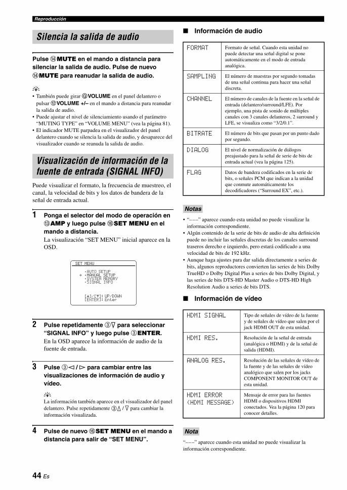
Reproducción
Pulse DMUTE en el mando a distancia para silenciar la salida de audio. Pulse de nuevo DMUTE para reanudar la salida de audio.
y• También puede girar QVOLUME en el panel delantero o
pulsar BVOLUME +/– en el mando a distancia para reanudar la salida de audio.
• Puede ajustar el nivel de silenciamiento usando el parámetro “MUTING TYPE” en “VOLUME MENU” (vea la página 81).
• El indicador MUTE parpadea en el visualizador del panel delantero cuando se silencia la salida de audio, y desaparece del visualizador cuando se reanuda la salida de audio.
Puede visualizar el formato, la frecuencia de muestreo, el canal, la velocidad de bits y los datos de bandera de la señal de entrada actual.
1 Ponga el selector del modo de operación en CAMP y luego pulse FSET MENU en el mando a distancia.La visualización “SET MENU” inicial aparece en la OSD.
2 Pulse repetidamente 3n para seleccionar “SIGNAL INFO” y luego pulse 3ENTER.En la OSD aparece la información de audio de la fuente de entrada.
3 Pulse 3l / h para cambiar entre las visualizaciones de información de audio y vídeo.
yLa información también aparece en el visualizador del panel delantero. Pulse repetidamente 3k / n para cambiar la información visualizada.
4 Pulse de nuevo FSET MENU en el mando a distancia para salir de “SET MENU”.
Información de audio
• “–––” aparece cuando esta unidad no puede visualizar la información correspondiente.
• Algún contenido de la serie de bits de audio de alta definición puede no incluir las señales discretas de los canales surround traseros derecho e izquierdo, pero estará codificado a una velocidad de bits de 192 kHz.
• Aunque haga ajustes para dar salida directamente a series de bits, algunos reproductores convierten las series de bits Dolby TrueHD o Dolby Digital Plus a series de bits Dolby Digital, y las series de bits DTS-HD Master Audio o DTS-HD High Resolution Audio a series de bits DTS.
Información de vídeo
“–––” aparece cuando esta unidad no puede visualizar la información correspondiente.
Silencia la salida de audio
Visualización de información de la fuente de entrada (SIGNAL INFO)
[]/[]:[ENTER]:
[ p
SET MENU
;AUTO SETUP;MANUAL SETUP;SYSTEM MEMORY;SIGNAL INFO
UP/DOWNEnter
.
FORMAT Formato de señal. Cuando esta unidad no puede detectar una señal digital se pone automáticamente en el modo de entrada analógica.
SAMPLING El número de muestras por segundo tomadas de una señal continua para hacer una señal discreta.
CHANNEL El número de canales de la fuente en la señal de entrada (delantero/surround/LFE). Por ejemplo, una pista de sonido de múltiples canales con 3 canales delanteros, 2 surround y LFE, se visualiza como “3/2/0.1”.
BITRATE El número de bits que pasan por un punto dado por segundo.
DIALOG El nivel de normalización de diálogos preajustado para la señal de serie de bits de entrada actual (vea la página 125).
FLAG Datos de bandera codificados en la serie de bits, o señales PCM que indican a la unidad que conmute automáticamente los decodificadores (“Surround EX”, etc.).
Notas
HDMI SIGNAL Tipo de señales de vídeo de la fuente y de señales de vídeo que salen por el jack HDMI OUT de esta unidad.
HDMI RES. Resolución de la señal de entrada (analógica o HDMI) y de la señal de salida (HDMI).
ANALOG RES. Resolución de las señales de vídeo de la fuente y de las señales de vídeo analógico que salen por los jacks COMPONENT MONITOR OUT de esta unidad.
HDMI ERROR(HDMI MESSAGE)
Mensaje de error para las fuentes HDMI o dispositivos HDMI conectados. Vea la página 120 para conocer detalles.
Nota
44 Es
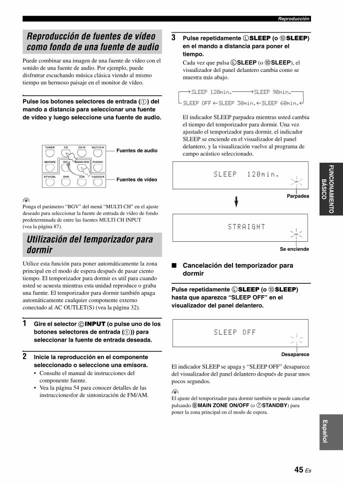
ReproducciónE
spañ
ol
FUN
CIO
NA
MIEN
TO
BÁ
SICO
Puede combinar una imagen de una fuente de vídeo con el sonido de una fuente de audio. Por ejemplo, puede disfrutrar escuchando música clásica viendo al mismo tiempo un hermoso paisaje en el monitor de vídeo.
Pulse los botones selectores de entrada (1) del mando a distancia para seleccionar una fuente de vídeo y luego seleccione una fuente de audio.
yPonga el parámetro “BGV” del menú “MULTI CH” en el ajuste deseado para seleccionar la fuente de entrada de vídeo de fondo predeterminada de entre las fuentes MULTI CH INPUT (vea la página 87).
Utilice esta función para poner automáticamente la zona principal en el modo de espera después de pasar ciento tiempo. El temporizador para dormir es util para cuando usted se acuesta mientras esta unidad reproduce o graba una fuente. El temporizador para dormir también apaga automáticamente cualquier componente externo conectado al AC OUTLET(S) (vea la página 32).
1 Gire el selector CINPUT (o pulse uno de los botones selectores de entrada (1)) para seleccionar la fuente de entrada deseada.
2 Inicie la reproducción en el componente seleccionado o seleccione una emisora.• Consulte el manual de instrucciones del
componente fuente.• Vea la página 54 para conocer detalles de las
instruccionesfor de sintonización de FM/AM.
3 Pulse repetidamente LSLEEP (o 0SLEEP) en el mando a distancia para poner el tiempo.Cada vez que pulsa LSLEEP (o 0SLEEP), el visualizador del panel delantero cambia como se muestra más abajo.
El indicador SLEEP parpadea mientras usted cambia el tiempo del temporizador para dormir. Una vez ajustado el temporizador para dormir, el indicador SLEEP se enciende en el visualizador del panel delantero, y la visualización vuelve al programa de campo acústico seleccionado.
Cancelación del temporizador para dormir
Pulse repetidamente LSLEEP (o 0SLEEP) hasta que aparezca “SLEEP OFF” en el visualizador del panel delantero.
El indicador SLEEP se apaga y “SLEEP OFF” desaparece del visualizador del panel delantero después de pasar unos pocos segundos.
yEl ajuste del temporizador para dormir también se puede cancelar pulsando BMAIN ZONE ON/OFF (o 7STANDBY) para poner la zona principal en el modo de espera.
Reproducción de fuentes de vídeo como fondo de una fuente de audio
Utilización del temporizador para dormir
DTV/CBL VCRDVR V-AUX/DOCK
TUNER CD CD-R MULTI CH IN
DVD BD/HD DVD PHONOMD/TAPE
Fuentes de audio
Fuentes de vídeo
SLEEP 120min. SLEEP 90min.
SLEEP 60min.SLEEP 30min.SLEEP OFF
SLEEP
S L E E P 1 2 0 m i n .
Parpadea
SLEEP
S T R A I G H T
Se enciende
S L E E P O F F
Desaparece
45 Es

Esta unidad está equipada con una variedad de decodificadores digitales precisos que le permiten disfrutar de la reproducción de múltiples canales de casi cualquier fuente de sonido estéreo o multicanal. También esta equipada con un chip de procesamiento digital Yamaha (DSP) que contiene varios programas de campos acústicos que usted puede utilizar para realzar la calidad de la reproducción.
y• Los programas de campos acústicos Yamaha CINEMA DSP son compatibles con todas las fuentes Dolby Digital, DTS,
Dolby Surround, Dolby TrueHD y DTS-HD Master Audio.• Los programas de campos acústicos Yamaha HiFi DSP recrean los ambientes acústicos verdaderos creados con mediciones precisas
tomadas en salas de conciertos, lugares donde se interpreta música, cines, etc. Por lo tanto puede que usted note variaciones en la intensidad de los reflejos procedentes de las partes delanteras, trasera, izquierda y derecha.
• Puede cambiar los parámetros de los campos acústicos. Vea la página 64 para conocer detalles.
Gire el selector NPROGRAM (o ponga el selector del modo de operación en CAMP y luego pulse repetidamente uno de los botones selectores de campo acústico (N)).El nombre del programa de campo acústico seleccionado aparece en el visualizador del panel delantero y en la OSD.
• Cuando selecciona una fuente de entrada, esta unidad selecciona automáticamente el último programa acústico utilizado con la fuente de entrada correspondiente.
• Los programas de campos acústicos no se pueden seleccionar cuando el componente conectado a los jacks MULTI CH INPUT se selecciona como fuente de entrada (vea la página 43) o cuando esta unidad está en el modo Pure Direct (vea la página 52).
• Cuando reproduce fuentes DTS 96/24 con cualquier programa de campo acústico, esta unidad aplica el programa seleccionado sin activar el decodificador DTS 96/24.
• Las frecuencias de muestreo superiores a 48 kHz se reducen a 48 kHz y luego se aplican los programas de campos acústicos.
ySeleccione un programa de campo acústico según sus preferencias de escucha, y no se base en el nombre del programa, etc.
Programas de campos acústicos
Selección de programas de campos acústicos
Notas
Descripciones de programas de campos acústicos
Indicadores de campo acústico
DIALOG LIFTSB ROOM SIZES. ROOM SIZESB INIT. DLYS.INIT. DLY
P.ROOM SIZE
Sci-FiMOVIE
P.INIT. DLYSUR.DSP LEVEL
8
MOVIE
Este programa reproduce claramente el sonido de ciencia ficción y los efectos especiales más recientes de las películas de cine. Puede disfrutar de una variedad de espacios virtuales creados cinematográficamente, en los que se pueden separar claramente los diálogos, los efectos de sonido y la música de fondo.
Parámetros de campos acústicos disponibles (vea la página 66) Descripción del programa
Botón de mando a distancia
Nombre del programa
Campos acústicos creados
CINEMA DSP o HiFi DSP
Categoría del programa
Campo acústico de presencia
Posición de escucha
Campo acústico de altavoz surround izquierdo
Campo acústico de altavoz surround derecho
Campo acústico de altavoz surround trasero
46 Es

Programas de campos acústicosE
spañ
ol
FUN
CIO
NA
MIEN
TO
BÁ
SICO
Para fuentes de música
yPara las fuentes de música también recomendamos usar el modo Pure Direct (vea la página 52), el modo “STRAIGHT” (vea la página 51) o el modo de decodificador surround (vea la página 69).
CLASSICAL Hall in Munich
Este campo acústico simula una sala de conciertos de unas 2500 butacas en Munich, con un elegante acabado interior en madera como es normal en las salas de concierto de Europa. Las reverberaciones elegantes y hermosas se propagan creando un atmósfera tranquilizante. El asiento virtual del oyente está en la parte central izquierda de la sala.
DSP LEVELINIT. DLY
ROOM SIZELIVENESS
DIALOG LIFT
CLASSICAL Hall in Vienna
Ésta es una sala de conciertos media de unas 1700 butacas, en forma de caja de zapatos como es habitual en Viena. Las columnas y las tallas de adorno crean reflejos muy complejos de todo alrededor de los oyentes que producen un sonido completo e intenso.
DSP LEVELINIT. DLY
ROOM SIZELIVENESS
DIALOG LIFT
7
ENTERTAIN
5
CLASSICAL
HiFi DSP
7
ENTERTAIN
5
CLASSICAL
HiFi DSP
CLASSICAL Hall in Amsterdam
La sala grande en forma de caja de zapatos tiene unas 2200 localidades dispuestas alrededor de un escenario circular. Los reflejos son ricos y agradables, y el sonido se desplaza libremente.
DSP LEVELINIT. DLY
ROOM SIZELIVENESS
DIALOG LIFT
CLASSICAL Church in Freiburg
Situada en el sur de Alemania, esta iglesia grande de piedra tiene una torre puntiaguda de 120 metros de altura. Su forma larga y estrecha y su techo alto producen un tiempo de reverberación prolongado y un tiempo de reflexión inicial limitado. Por lo tanto, más bien la reverberación rica, y no el propio sonido, es la que reproduce la atmósfera de iglesia.
DSP LEVELINIT. DLY
LIVENESSREV.TIME
REV.DELAYREV. LEVEL
DIALOG LIFT
CLASSICAL Chamber
Este programa crea un espacio relativamente amplio con un techo alto como, por ejemplo, el de una sala de audiencias de un palacio. Ofrece reverberaciones agradables que son adecuadas para la música suave o de cámara.
DSP LEVELINIT. DLY
LIVENESSREV.TIME
REV.DELAYREV. LEVEL
DIALOG LIFT
LIVE/CLUB Village Vanguard
El club de jazz está en la Séptima Avenida, New York. Este pequeño club de techo bajo produce una reflexiones potentes que convergen en el escenario ubicado en una esquina.
DSP LEVELINIT. DLY
ROOM SIZELIVENESS
DIALOG LIFT
LIVE/CLUB Warehouse Loft
El almacén se parece a algunos áticos de Soho. El sonido se refleja claramente en las paredes de cemento con mucha energía.
DSP LEVELINIT. DLY
ROOM SIZELIVENESS
REV.TIMEREV.DELAY
REV. LEVELDIALOG LIFT
7
ENTERTAIN
5
CLASSICAL
HiFi DSP
7
ENTERTAIN
5
CLASSICAL
HiFi DSP
5
CLASSICAL
HiFi DSP
6
LIVE/CLUB
HiFi DSP
6
LIVE/CLUB
HiFi DSP
47 Es
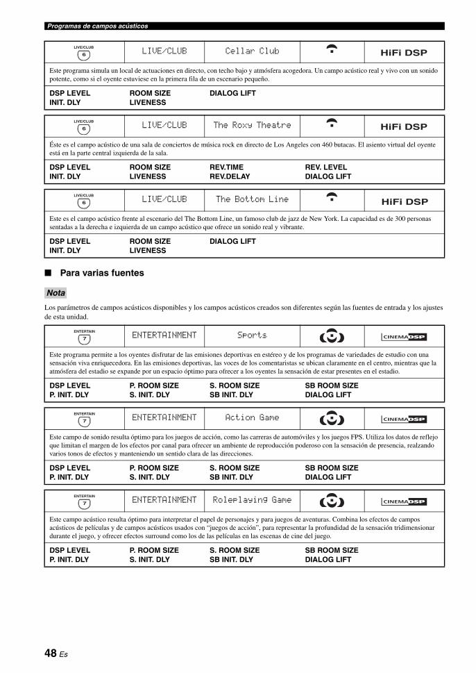
Programas de campos acústicos
Para varias fuentes
Los parámetros de campos acústicos disponibles y los campos acústicos creados son diferentes según las fuentes de entrada y los ajustes de esta unidad.
LIVE/CLUB Cellar Club
Este programa simula un local de actuaciones en directo, con techo bajo y atmósfera acogedora. Un campo acústico real y vivo con un sonido potente, como si el oyente estuviese en la primera fila de un escenario pequeño.
DSP LEVELINIT. DLY
ROOM SIZELIVENESS
DIALOG LIFT
LIVE/CLUB The Roxy Theatre
Éste es el campo acústico de una sala de conciertos de música rock en directo de Los Angeles con 460 butacas. El asiento virtual del oyente está en la parte central izquierda de la sala.
DSP LEVELINIT. DLY
ROOM SIZELIVENESS
REV.TIMEREV.DELAY
REV. LEVELDIALOG LIFT
LIVE/CLUB The Bottom Line
Este es el campo acústico frente al escenario del The Bottom Line, un famoso club de jazz de New York. La capacidad es de 300 personas sentadas a la derecha e izquierda de un campo acústico que ofrece un sonido real y vibrante.
DSP LEVELINIT. DLY
ROOM SIZELIVENESS
DIALOG LIFT
Nota
ENTERTAINMENT Sports
Este programa permite a los oyentes disfrutar de las emisiones deportivas en estéreo y de los programas de variedades de estudio con una sensación viva enriquecedora. En las emisiones deportivas, las voces de los comentaristas se ubican claramente en el centro, mientras que la atmósfera del estadio se expande por un espacio óptimo para ofrecer a los oyentes la sensación de estar presentes en el estadio.
DSP LEVELP. INIT. DLY
P. ROOM SIZES. INIT. DLY
S. ROOM SIZESB INIT. DLY
SB ROOM SIZEDIALOG LIFT
ENTERTAINMENT Action Game
Este campo de sonido resulta óptimo para los juegos de acción, como las carreras de automóviles y los juegos FPS. Utiliza los datos de reflejo que limitan el margen de los efectos por canal para ofrecer un ambiente de reproducción poderoso con la sensación de presencia, realzando varios tonos de efectos y manteniendo un sentido clara de las direcciones.
DSP LEVELP. INIT. DLY
P. ROOM SIZES. INIT. DLY
S. ROOM SIZESB INIT. DLY
SB ROOM SIZEDIALOG LIFT
ENTERTAINMENT Roleplaying Game
Este campo acústico resulta óptimo para interpretar el papel de personajes y para juegos de aventuras. Combina los efectos de campos acústicos de películas y de campos acústicos usados con “juegos de acción”, para representar la profundidad de la sensación tridimensionar durante el juego, y ofrecer efectos surround como los de las películas en las escenas de cine del juego.
DSP LEVELP. INIT. DLY
P. ROOM SIZES. INIT. DLY
S. ROOM SIZESB INIT. DLY
SB ROOM SIZEDIALOG LIFT
6
LIVE/CLUB
HiFi DSP
6
LIVE/CLUB
HiFi DSP
6
LIVE/CLUB
HiFi DSP
7
ENTERTAIN
7
ENTERTAIN
7
ENTERTAIN
48 Es
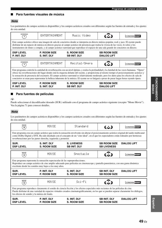
Programas de campos acústicosE
spañ
ol
FUN
CIO
NA
MIEN
TO
BÁ
SICO
Para fuentes visuales de música
Los parámetros de campos acústicos disponibles y los campos acústicos creados son diferentes según las fuentes de entrada y los ajustes de esta unidad.
Para fuentes de películas
yPuede seleccionar el decodificador deseado (SUR.) utilizado con el programa de campo acústico siguiente (excepto “Mono Movie”). Vea la página 71 para conocer detalles.
Los parámetros de campos acústicos disponibles y los campos acústicos creados son diferentes según las fuentes de entrada y los ajustes de esta unidad.
Nota
ENTERTAINMENT Music Video
Este campo acústico ofrece una imagen de sala de conciertos donde se interpreta en directo música popular, rock y jazz. El oyente puede disfrutar de un espacio de música en directo gracias al campo acústico de presencia que realza la viveza de las voces, lo solos y los instrumentos de ritmo y compás, y al campo acústico surround que reproduce el espacio de una sala grande de conciertos en directo.
DSP LEVELP. INIT. DLY
P. ROOM SIZES. INIT. DLY
S. ROOM SIZESB INIT. DLY
SB ROOM SIZEDIALOG LIFT
ENTERTAINMENT Recital/Opera
Este programa controla la cantidad de reverberación con un nivel óptimo, y realza la profundidad y la claridad de las voces humanas. “Opera” ofrece las reverberaciones del lugar donde está la orquesta delante del oyente, y proporciona al mismo tiempo el posicionamiento acústico y la sensación de presencia del escenario. El campo acústico surround es relativamente moderado, pero los datos para los efectos de sala de conciertos se usan para representar la belleza inherente de la música. El oyente no se fatigará a pesar de pasar largas horas oyendo ópera.
DSP LEVELP. INIT. DLY
P. ROOM SIZES. INIT. DLY
S. ROOM SIZESB INIT. DLY
SB ROOM SIZEDIALOG LIFT
Nota
6
LIVE/CLUB
7
ENTERTAIN
HiFi DSP
7
ENTERTAIN
MOVIE Standard
Este programa crea un campo acústico que realza la sensación envolvente sin alterar el posicionamiento acústico original del audio multicanal como Dolby Digital y DTS. Ha sido diseñado con el concepto de un “cine ideal”, en el que los espectadores están rodeados por hermosas reverberaciones por las partes derecha, izquierda y posterior.
SUR.DSP LEVEL
S. INIT. DLYS. ROOM SIZE
S. LIVENESSSB INIT. DLY
SB ROOM SIZESB LIVENESS
DIALOG LIFT
MOVIE Spectacle
Este programa representa la sensación espectacular de las superproducciones. Reproduce un campo acústico de cine amplio adecuado para películas en cinemascope y pantalla panorámica, con una gama dinámica excelente desde los sonidos muy bajos a los muy altos.
SUR.DSP LEVEL
P. INIT. DLYP. ROOM SIZE
S. INIT. DLYS. ROOM SIZE
SB INIT. DLYSB ROOM SIZE
DIALOG LIFT
8
MOVIE
8
MOVIE
MOVIE Sci-Fi
Este programa reproduce claramente el sonido de ciencia ficción y los efectos especiales más recientes de las películas de cine. Puede disfrutar de una variedad de espacios virtuales creados cinematográficamente, en los que se pueden separar claramente los diálogos, los efectos de sonido y la música de fondo.
SUR.DSP LEVEL
P. INIT. DLYP. ROOM SIZE
S. INIT. DLYS. ROOM SIZE
SB INIT. DLYSB ROOM SIZE
DIALOG LIFT
8
MOVIE
49 Es

Programas de campos acústicos
Reproducción estéreo
Compressed Music Enhancer
MOVIE Adventure
Este programa es ideal para reproducir con precisión el diseño del sonido de las películas de acción y aventuras.El campo acústico restringe las reverberaciones, pero realza la reproducción de un espacio potente expandido ampliamente a izquierda y derecha. La profundidad reproducida también se restringe relativamente para asegurar la separación entre los canales de audio y la claridad del sonido.
SUR.DSP LEVEL
P. INIT. DLYP. ROOM SIZE
S. INIT. DLYS. ROOM SIZE
SB INIT. DLYSB ROOM SIZE
DIALOG LIFT
8
MOVIE
MOVIE Drama
Este campo acústico proporciona reverberaciones estables que se adaptan a la amplia gama de géneros cinematográficos, desde dramas a musicales y comedias. Las reverberaciones son modestas, pero ofrecen una sensación tridimensional óptima, reproduciendo suavemente tonos de efectos y música de fondo, con las palabras claras y un posicionamiento central que no fatiga al oyente incluso después de pasar largas horas viendo programas.
SUR.DSP LEVEL
P. INIT. DLYP. ROOM SIZE
S. INIT. DLYS. ROOM SIZE
SB INIT. DLYSB ROOM SIZE
DIALOG LIFT
8
MOVIE
MOVIE Mono Movie
Este programa sirve para reproducir fuentes de vídeo mono, como el de películas clásicas, en el ambiente de un buen cine antiguo.El programa produce una expansión y reverberación óptimas en el audio original para crear un espacio confortable con cierta profundidad de sonido.
DSP LEVELINIT. DLY
ROOM SIZELIVENESS
REV.TIMEREV. LEVEL
REV.DELAYDIALOG LIFT
STEREO 2ch Stereo
Use este programa para mezclar fuentes multicanales en 2 canales. Vea la página 53 para conocer detalles.
DIRECT
8
MOVIE
9
STEREO
STEREO 7ch Stereo
Use este programa para dar salida al sonido de todos los altavoces. Cuando reproduzca fuentes de múltiples canales, esta unidad mezclará las fuentes en 2 canales, y luego dará salida al sonido por todos los altavoces. Este programa crea un campo acústico más grande, y es ideal para música de fondo en fiestas, etc.
CT LEVELSL LEVEL
SR LEVELSB LEVEL
PL LEVELPR LEVEL
MUSIC ENHANCER Straight Enhancer
Use este programa para mejorar el sonido más parecido a la profundidad y amplitud originales de los artefactos de compresión de múltiples canales y de 2 canales.
EFFECT LEVEL
9
STEREO
HiFi DSP
6
ENHANCER
MUSIC ENHANCER 7ch Enhancer
Use este programa para reproducir artefactos de compresión en estéreo de 7 canales.
EFFECT LEVEL
6
ENHANCER
50 Es

Programas de campos acústicosE
spañ
ol
FUN
CIO
NA
MIEN
TO
BÁ
SICO
Uso de programas de campos acústicos sin altavoces surround (Virtual CINEMA DSP)
Virtual CINEMA DSP le permite disfrutar de los programas de campos acústicos CINEMA DSP o HiFi DSP sin altavoces surround. Esto crea altavoces virtuales para reproducir el campo acústico natural.Cuando ponga “SUR. L/R SP” en “NONE” (vea la página 78), Virtual CINEMA DSP se activa automáticamente siempre que usted selecciona un programa de campo acústico CINEMA DSP o HiFi DSP (vea la página 46).
Virtual CINEMA DSP no se activará aunque “SUR. L/R SP” se ponga en “NONE” (vea la página 78) en los casos siguientes:
– cuando el componente conectado a los jacks MULTI CH INPUT está seleccionado como fuente de entrada (vea la página 43).
– cuando se conecten auriculares al jack PHONES.– cuando esta unidad está en el modo “7ch Stereo”.
Para disfrutar de fuentes de múltiples canales y programas de campos acústicos con auriculares (SILENT CINEMA)
SILENT CINEMA le permite disfrutar de la música o sonido de películas de múltiples canales con auriculares convencionales. SILENT CINEMA se activa automáticamente siempre que usted conecta auriculares al jack PHONES mientras escucha programas de campos acústicos CINEMA DSP o HiFi DSP (vea la página 46). Cuando se activa, el indicador SILENT CINEMA se enciende en el visualizador del panel delanero.
• SILENT CINEMA no se activa cuando el componente conectado a los jacks MULTI CH INPUT se selecciona como fuente de entrada (vea la página 43).
• SILENT CINEMA no es eficaz cuando se selecciona el modo Pure Direct (vea la página 52) o “2ch Stereo” (vea la página 53), ni cuando esta unidad está en el modo “STRAIGHT”.
Cuando esta unidad esté en el modo “STRAIGHT”, las fuentes estéreo de 2 canales sólo saldrán por los altavoces delanteros derecho e izquierdo. Las fuentes de múltiples canales se decodifican directamente para los canales apropiados sin ningún proceso de efectos adicional.
Pulse OSTRAIGHT (o HSTRAIGHT) para seleccionar “STRAIGHT”.
yLos nombres del formato de la señal de audio de la fuente de entrada y del decodificador activo aparecen en el visualizador del panel delantero.
Desactivación del modo “STRAIGHT”
Pulse OSTRAIGHT (o HSTRAIGHT) para que “STRAIGHT” desaparezca del visualizador del panel delantero.El efecto de sonido se activa de nuevo.
yTambién puede seleccionar el programa de campo acústico deseado girando el selector NPROGRAM (o pulsando repetidamente uno de los botones de programa de campo acústico deseado (N)).
Nota
Notas
Antes de hacer las operaciones siguientes, ponga el selector del modo de operación del mando a distancia en CAMP.
Para disfrutar de fuentes de entrada sin procesar
STRAIGHT
51 Es

Use el modo Pure Direct para disfrutar del sonido de fidelidad pura de la fuente seleccionada. Cuando el modo Pure Direct esté activado, esta unidad reproducirá la fuente seleccionara con la circuitería de sonido puro.
Pulse MPURE DIRECT (o EPURE DIRECT) para activar o desactivar el modo Pure Direct.El botón MPURE DIRECT del panel delantero se enciende y el visualizador del panel delantero se apaga automáticamente mientras esta unidad está en el modo Pure Direct.
• Cuando esta unidad está en el modo Pure Direct no da salida a ninguna señal de vídeo por los jacks MONITOR OUT y por el jack HDMI OUT.
• Cuando ponga el ajuste de selección del jack de entrada de audio en “AUTO”, “HDMI” o “COAX/OPT” (vea la página 43) y reproduzca fuentes PCM multicanal o de series de bits, esta unidad activará el decodificador correspondiente.
• Las operaciones siguientes no se pueden hacer cuando la unidad está en el modo Pure Direct:– cambio del programa de campo acústico– visualización de la OSD– ajuste de los parámetros “SET MENU” (excepto para el ajuste
de nivel de los altavoces)– operación de funciones de vídeo (conversiones de vídeo, etc.)
• El modo Pure Direct se cancela automáticamente siempre que se apaga esta unidad.
yEl visualizador del panel delantero se enciende momentáneamente cuando se realiza una operación.
Use esta función para ajustar el balance de graves y agudos para los canales de los altavoces delanteros derecho/izquierdo y central, y para el canal del altavoz de subgraves.
1 Pulse repetidamente ETONE CONTROL en el panel delantero para seleccionar la respuesta de alta frecuencia (TREBLE) o la de baja frecuencia (BASS).
2 Gire el selector NPROGRAM para ajustar la respuesta de alta frecuencia (TREBLE) o de baja frecuencia (BASS).Margen de control: –6,0 dB a +6,0 dB
• Si aumenta o disminuye el sonido de alta o baja frecuencia a niveles extremos, la calidad tonal de los altavoces surround no será adecuada para los altavoces delanteros derecho/izquierdo, central y de subgraves.
• TONE CONTROL no es eficaz cuando se activa el modo Pure Direct o cuando se selecciona MULTI CH como fuente de entrada.
Uso de las características de audio
Antes de hacer las operaciones siguientes, ponga el selector del modo de operación del mando a distancia en CAMP.
Para disfrutar del sonido hi-fi puro
Notas
Ajuste de la calidad tonal
Notas
52 Es

Uso de las características de audioE
spañ
ol
FUN
CIO
NA
MIEN
TO
BÁ
SICO
Puede ajustar el nivel de salida de cada altavoz mientras escucha una fuente de música. Esto también es posible cuando se reproducen fuentes introducidas por los jacks MULTI CH INPUT.
Esta operación anulará los ajustes de nivel hechos en “Optimización de los ajustes de los altavoces para su habitación de escucha” (vea la página 37) y “SPEAKER LEVEL” (vea la página 79).
1 Pulse repetidamente 2LEVEL en el mando a distancia para seleccionar el altavoz que quiera ajustar.
y• Una vez pulsado 2LEVEL en el mando a distancia
también puede seleccionar el altavoz pulsando 3k / n.• En lugar de “SB R” y “SB L” se visualiza “SB” si
“SUR. B L/R SP” se pone en “SMLx1” o “LRGx1” (vea la página 78).
2 Pulse 3l / h en el mando a distancia para ajustar el nivel de salida del altavoz.• Pulse 3h para aumentar el valor.• Pulse 3l para disminuir el valor.Margen de control: –10,0 dB a +10,0 dB
Puede mezclar descendentemente fuentes de 2 canales y disfrutar de la reproducción en estéreo de 2 canales.
Pulse repetidamente NSTEREO en el mando a distancia para seleccionar “2ch Stereo”.
y• Cuando “LFE/BASS OUT” se ponga en “SWFR” o “BOTH”
(vea la página 77) podrá usar un altavoz de subgraves con este programa.
• También puede seleccionar el modo “2ch Stereo” girando el selector NPROGRAM del panel delantero.
• Vea la página 69 para conocer detalles de los parámetros del modo “2ch Stereo”.
Antes de hacer las operaciones siguientes, ponga el selector del modo de operación del mando a distancia en CAMP.
Ajuste de nivel de los altavoces
Nota
Visualizador Altavoz ajustado
FRONT L Altavoz delantero izquierdo
CENTER Altavoz central
FRONT R Altavoz delantero derecho
SUR.R Altavoz surround derecho
SB R Altavoz surround trasero derecho
SB L Altavoz surround trasero izquierdo
SUR.L Altavoz surround izquierdo
SWFR Altavoz de subgraves
PRNS L Altavoz izquierdo de presencia
PRNS R Altavoz derecho de presencia
Para disfrutar de fuentes de múltiples canales en estéreo de 2 canales
53 Es

Hay 2 métodos de sintonizar: automático y manual. La sintonización automática es eficaz cuando las señales de emisoras son intensas y no hay interferencias. Si la señal de la emisora que selecciona es débil, sintonícela manualmente. También puede utilizar las funciones de presintonización automática y manual para guardar hasta 40 emisoras (A1 a E8: 8 números de emisoras presintonizadas en cada uno de los 5 grupos de emisoras presintonizadas). Además, puede llamar a cualquier emisora presintonizada e intercambiar la asignación de dos emisoras presintonizadas entre ellas.
Oriente las antenas de FM y AM conectadas para obtener la mejor recepción.
La sintonización automática es eficaz cuando las señales de emisoras son intensas y no hay interferencias.
1 Gire el selector CINPUT del panel delantero para seleccionar “TUNER” como fuente de entrada.
2 Pulse IFM/AM para seleccionar la banda de recepción.“FM” o “AM” aparece en el visualizador del panel delantero.
3 Pulse KTUNING MODE para que el indicador AUTO se encienda en el visualizador del panel delantero.
Si aparecen dos puntos (:) en el visualizador del panel delantero no se podrá sintonizar. Pulse HPRESET/TUNING para apagar los dos puntos (:).
4 Pulse una vez GPRESET/TUNING l / h para iniciar la sintonización automática.Cuando esta unidad sintoniza una emisora, el indicador TUNED se enciende y la frecuencia de la emisora recibida se muestra en el visualizador del panel delantero.• Pulse Gh para sintonizar una frecuencia más alta.• Pulse Gl para sintonizar una frecuencia más
baja.
Si la señal recibida de la emisora que quiere seleccionar es débil, sintonícela manualmente.
La sintonización manual de una emisora de FM cambia automáticamente el modo de recepción a mono para aumentar la calidad de la señal.
1 Gire el selector CINPUT del panel delantero para seleccionar “TUNER” como fuente de entrada.
2 Pulse IFM/AM para seleccionar la banda de recepción.“FM” o “AM” aparece en el visualizador del panel delantero.
3 Pulse KTUNING MODE para que el indicador AUTO desaparezca del visualizador del panel delantero.
Si aparecen dos puntos (:) en el visualizador del panel delantero no se podrá sintonizar. Pulse HPRESET/TUNING para apagar los dos puntos (:).
4 Pulse GPRESET/TUNING l / h para sintonizar manualmente la emisora deseada.Mantenga pulsado el botón para continuar buscando.
Sintonización de FM/AM
Nota
Sintonización automática
AUTO
A F M 9 7 . 7 0 M H z
Se enciendeSin dos puntos (:)
Sintonización manual
Nota
A F M 9 7 . 7 0 M H z
Sin dos puntos (:)
54 Es

Sintonización de FM/AME
spañ
ol
FUN
CIO
NA
MIEN
TO
BÁ
SICO
Puede utilizar la función de presintonización automática para guardar en orden hasta 40 emisoras de FM de señal intensa (A1 a E8: 8 números de emisoras presintonizadas en cada uno de los 5 grupos de emisoras presintonizadas). Luego puede sintonizar fácilmente cualquier emisora presintonizada seleccionando el número de la misma.
1 Gire el selector CINPUT del panel delantero para seleccionar “TUNER” como fuente de entrada.
2 Pulse IFM/AM para seleccionar “FM” como banda de recepción.“FM” aparece en el visualizador del panel delantero.
3 Mantenga pulsado JMEMORY durante más de 3 segundos.El número de la emisora presintonizada y los indicadores AUTO y MEMORY parpadearán. Después de unos 5 segundos empieza la presintonía automática desde la frecuencia actual y ésta avanza hacia las frecuencias más altas.
Cuando termina la presintonización automática, el visualizador del panel delantero muestra la frecuencia de la última emisora presintonizada.
y• Puede especificar el número de emisora presintonizada a partir del
cual esta unidad almacena emisoras de FM. Pulse FA/B/C/D/E y luego pulse repetidamente GPRESET/TUNING l / h después de realizar el paso 3 para seleccionar el número de emisora presintonizada donde se va a guardar la primera emisora.
• Puede empezar a sintonizar hacia las frecuencias inferiores para guardar automáticamente emisoras de FM. Pulse HPRESET/TUNING para que los dos puntos (:) desaparezcan del visualizador del panel delantero y luego pulse GPRESET/TUNING l después de mantener pulsado JMEMORY durante más de 3 segundos.
• Cualquier dato de emisora guardado bajo un número de emisora presintonizada se cancela al guardar una emisora nueva bajo el mismo número de emisora presintonizada.
• Si el número de las emisoras recibidas no alcanza 40 (E8), la presintonización automática se detiene automáticamente después de buscar todas las emisoras disponibles.
• Sólo las emisoras de FM con suficiente intensidad de señal se guardan automáticamente mediante la presintonización automática. Si la emisora que quiere guardar tiene una intensidad de señal débil, sintónicela manualmente y guárdela como se describe en “Presintonización manual”.
• (Modelo de Europa solamente) Sólo las emisoras del sistema de datos de radio se guardan automáticamente mediante la presintonización automática.
También puede guardar manualmente hasta 40 emisoras (A1 a E8: 8 números de emisoras presintonizadas en cada uno de los 5 grupos de emisoras presintonizadas).
1 Sintonice una emisora automática o manualmente.Vea la página 54 para conocer las instrucciones de sintonización.
2 Pulse JMEMORY en el panel delantero.El indicador MEMORY parpadea en el visualizador del panel delantero durante unos 10 segundos.
3 Pulse repetidamente FA/B/C/D/E para seleccionar un grupo de emisoras presintonizadas (A a E) mientras el indicador MEMORY está parpadeando.La letra del grupo de emisoras presintonizadas seleccionado aparece. Verifique que los dos puntos (:) aparezcan en el visualizador del panel delantero.
Presintonización automática
AUTO MEMORY
A 1 : F M 9 7 . 7 0 M H z
Parpadea Parpadea
Notas
Presintonización manual
MEMORY
Parpadea
MEMORY
A : F M 9 7 . 7 0 M H z
Grupo de emisoras presintonizadas
ParpadeaDos puntos (:)
55 Es
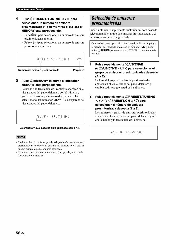
Sintonización de FM/AM
4 Pulse GPRESET/TUNING l / h para seleccionar un número de emisora presintonizada (1 a 8) mientras el indicador MEMORY está parpadeando.• Pulse Gh para seleccionar un número de emisora
presintonizada superior.• Pulse Gl para seleccionar un número de emisora
presintonizada inferior.
5 Pulse JMEMORY mientras el indicador MEMORY está parpadeando.La banda y la frecuencia de la emisora aparecen en el visualizador del panel delantero con el número y grupo de emisoras presintonizadas que usted ha seleccionado. El indicador MEMORY desaparece del visualizador del panel delantero.
• Cualquier dato de emisora guardado bajo un número de emisora presintonizada se cancela al guardar una emisora nueva bajo el mismo número de emisora presintonizada.
• El modo de recepción (estéreo o mono) se guarda junto con la frecuencia de la emisora.
Puede sintonizar simplemente cualquier emisora deseada seleccionando el grupo de emisoras presintonizadas y el número bajo el cual fue guardada.
1 Pulse repetidamente FA/B/C/D/E (o 3A/B/C/D/E l / h) para seleccionar el grupo de emisoras presintonizadas deseado (A a E).La letra del grupo de emisoras presintonizadas aparece en el visualizador del panel delantero y cambia cada vez que usted pulsa el botón.
2 Pulse repetidamente GPRESET/TUNING l / h (o 3PRESET/CH k / n) para seleccionar el número de emisora presintonizada deseada (1 a 8).Los números y grupos de emisoras presintonizadas aparece en el visualizador del panel delantero junto con la banda y la frecuencia de la emisora.
Notas
MEMORY
A 1 : F M 9 7 . 7 0 M H z
Número de emisora presintonizada Parpadea
A 1 : F M 9 7 . 7 0 M H z
La emisora visualizada ha sido guardada como A1.
Selección de emisoras presintonizadas
Cuando haga esta operación con el mando a distancia, ponga el selector del modo de operación en CSOURCE y luego pulse 1TUNER para seleccionar “TUNER” como fuente de entrada.
A 1 : F M 9 7 . 7 0 M H z
56 Es
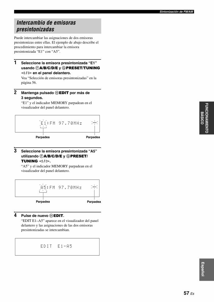
Sintonización de FM/AME
spañ
ol
FUN
CIO
NA
MIEN
TO
BÁ
SICO
Puede intercambiar las asignaciones de dos emisoras presintonizas entre ellas. El ejemplo de abajo describe el procedimiento para intercambiar la emisora presintonizada “E1” con “A5”.
1 Seleccione la emisora presintonizada “E1” usando FA/B/C/D/E y GPRESET/TUNING l / h en el panel delantero.Vea “Selección de emisoras presintonizadas” en la página 56.
2 Mantenga pulsado HEDIT por más de 3 segundos.“E1” y el indicador MEMORY parpadean en el visualizador del panel delantero.
3 Seleccione la emisora presintonizada “A5” utilizando FA/B/C/D/E y GPRESET/TUNING l / h.“A5” y el indicador MEMORY parpadean en el visualizador del panel delantero.
4 Pulse de nuevo HEDIT.“EDIT E1–A5” aparece en el visualizador del panel delantero y las asignaciones de las dos emisoras presintonizadas se intercambian.
Intercambio de emisoras presintonizadas
MEMORY
E 1 : F M 9 7 . 7 0 M H z
ParpadeaParpadea
MEMORY
A 5 : F M 9 7 . 7 0 M H z
ParpadeaParpadea
E D I T E 1 - A 5
57 Es

El sistema de datos de radio es un sistema de transmisión de datos de emisoras FM de muchos países. Esta unidad puede recibir varios datos del sistema de datos de radio como PS (servicio de programas), PTY (tipo de programa), RT (texto de radio), CT (hora) y EON (otras redes mejoradas) cuando se reciben emisoras del sistema de datos de radio.
Use esta función para visualizar los 4 tipos de información del sistema de datos de radio: PS (servicio de programas), PTY (tipo de programa), RT (texto de radio) y CT (hora). El indicador correspondiente se enciende en el visualizador del panel delanero.
• Puede seleccionar uno de los modos de visualización del sistema de datos de radio sólo cuando el indicador del sistema de datos correspondiente se enciende en el visualizador del panel delantero. Puede que esta unidad tarde un poco en recibir todos los datos del sistema de datos de radio procedentes de la emisora.
• Sólo puede seleccionar los modos de visualización del sistema de datos de radio que ofrece la emisora.
• Si las señales que están siendo recibidas no son lo suficientemente intensas, esta unidad no podrá utilizar los datos del sistema de datos de radio. En particular, el modo “RT” requiere una gran cantidad de datos y puede no estar disponible incluso cuando otros modos de visualización del sistema de datos de radio sí lo están.
• En caso de una mala recepción, pulse KTUNING MODE en el panel delantero para que el indicador AUTO desaparezca del visualizador del panel delantero.
• Si la intensidad de la señal se debilita debido a interferencias externas mientras la unidad está recibiendo datos del sistema de datos de radio, puede que la recepción se corte repentinamente y “...WAIT” aparezca en el visualizador del panel delantero.
• Cuando se seleccione el modo “RT”, esta unidad podrá visualizar información del programa mediante un máximo de 64 caracteres alfanuméricos, incluyendo la diéresis. Los caracteres no disponibles se visualizan con “_” (subrayado).
• Si la recepción se interrumpe cuando se selecciona el modo “CT”, “CT WAIT” aparecerá en el visualizador del panel delantero.
1 Sintonice la emisora deseada del sistema de datos de radio.• Recomendamos usar la sintonización automática
de presintonías para sintonizar las emisoras del sistema de datos de radio (vea la página 55).
• También puede usar el modo PTY SEEK para sintonizar las emisoras presintonizadas deseadas del sistema de datos de radio.
2 Pulse repetidamente 6FREQ/TEXT en el mando a distancia para seleccionar el modo de visualización del sistema de datos de radio.
• Seleccione “PS” para visualizar el programa del sistema de datos de radio que está siendo recibido.
• Seleccione “PTY” para visualizar el tipo del programa del sistema de datos de radio que está siendo recibido.
• Seleccione “RT” para visualizar la información del programa del sistema de datos de radio que está siendo recibido.
• Seleccione “CT” para visualizar la hora actual.
Sintonización del sistema de datos de radio (Modelo de Europa solamente)
Visualización de información del sistema de datos de radio
Notas
CTRTPTYPS
Visualización de frequencias
58 Es

Sintonización del sistema de datos de radio (Modelo de Europa solamente)E
spañ
ol
FUN
CIO
NA
MIEN
TO
BÁ
SICO
Use esta función para seleccionar, según los tipos de programas, el programa de radio deseado de entre todas las emisoras presintonizadas del sistema de datos de radio.
yUse la sintonización automática de presintonías para presintonizar emisoras del sistema de datos de radio (vea la página 55).
1 Ponga el selector del modo de operación en CSOURCE y luego pulse 1TUNER en el mando a distancia para seleccionar “TUNER” como fuente de entrada.
2 Pulse repetidamente 2BAND para seleccionar “FM” como banda de recepción.
3 Pulse 6PTY SEEK MODE en el mando a distancia para poner esta unidad en el modo PTY SEEK.El nombre del tipo de programa o “NEWS” parpadea en el visualizador del panel delantero.
yPara cancelar el modo PTY SEEK, pulse de nuevo 6PTY SEEK MODE en el mando a distancia.
4 Pulse 3PRESET/CH k / n en el mando a distancia para seleccionar el tipo de programa deseado.El nombre del tipo de programa seleccionado aparece en el visualizador del panel delantero.
Selección del tipo de programa del sistema de datos de radio (Modo PTY SEEK)
Parpadea
NEWS
Tipo de programa Descripciones
NEWS Noticias
AFFAIRS Temas actuales
INFO Información general
SPORT Deportes
EDUCATE Educación
DRAMA Drama
CULTURE Cultura
SCIENCE Ciencia
VARIED Entretenimiento
POP M Música popular
ROCK M Música rock
M.O.R. M Música para todos (escucha fácil)
LIGHT M Clásica ligera
CLASSICS Clásica seria
OTHER M Otra música
Se enciende
POP M
59 Es
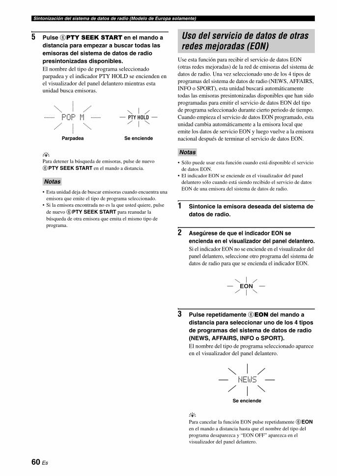
Sintonización del sistema de datos de radio (Modelo de Europa solamente)
5 Pulse 6PTY SEEK START en el mando a distancia para empezar a buscar todas las emisoras del sistema de datos de radio presintonizadas disponibles.El nombre del tipo de programa seleccionado parpadea y el indicador PTY HOLD se encienden en el visualizador del panel delantero mientras esta unidad busca emisoras.
yPara detener la búsqueda de emisoras, pulse de nuevo 6PTY SEEK START en el mando a distancia.
• Esta unidad deja de buscar emisoras cuando encuentra una emisora que emite el tipo de programa seleccionado.
• Si la emisora encontrada no es la que usted quiere, pulse de nuevo 6PTY SEEK START para reanudar la búsqueda de otra emisora que emita el mismo tipo de programa.
Use esta función para recibir el servicio de datos EON (otras redes mejoradas) de la red de emisoras del sistema de datos de radio. Una vez seleccionado uno de los 4 tipos de programas del sistema de datos de radio (NEWS, AFFAIRS, INFO o SPORT), esta unidad buscará automáticamente todas las emisoras presintonizadas disponibles que han sido programadas para emitir el servicio de datos EON del tipo de programa seleccionado durante cierto periodo de tiempo. Cuando empieza el servicio de datos EON programado, esta unidad cambia automáticamente a la emisora local que emite los datos de servicio EON y luego vuelve a la emisora nacional después de terminar el servicio de datos EON.
• Sólo puede usar esta función cuando está disponible el servicio de datos EON.
• El indicador EON se enciende en el visualizador del panel delantero sólo cuando está siendo recibido el servicio de datos EON de una emisora del sistema de datos de radio.
1 Sintonice la emisora deseada del sistema de datos de radio.
2 Asegúrese de que el indicador EON se encienda en el visualizador del panel delantero.Si el indicador EON no se enciende en el visualizador del panel delantero, seleccione otro programa del sistema de datos de radio para que se encienda el indicador EON.
3 Pulse repetidamente 6EON del mando a distancia para seleccionar uno de los 4 tipos de programas del sistema de datos de radio (NEWS, AFFAIRS, INFO o SPORT).El nombre del tipo de programa seleccionado aparece en el visualizador del panel delantero.
yPara cancelar la función EON pulse repetidamente 6EON en el mando a distancia hasta que el nombre del tipo del programa desaparezca y “EON OFF” aparezca en el visualizador del panel delantero.
Notas
POP M PTY HOLD
Parpadea Se enciende
Uso del servicio de datos de otras redes mejoradas (EON)
Notas
EON
NEWS
Se enciende
60 Es

Esp
año
lFU
NC
ION
AM
IENTO
B
ÁSIC
O
Una vez acoplado su iPod en un acoplador universal Yamaha iPod (como el YDS-10, vendido separadamente) conectado al terminal DOCK de esta unidad (vea la página 31), usted podrá disfrutar de la reproducción de su iPod usando el mando a distancia suministrado. También podrá usar el modo Compressed Music Enhancer de esta unidad para mejorar la calidad del sonido de los artefactos de compresión (como el formato MP3) guardados en su iPod (vea la página 50).
• Sólo son compatibles los iPod (Click and Wheel), iPod nano y iPod mini.• Algunas funciones pueden no ser compatibles dependiendo del modelo o de la versión del software de su iPod.
y• Para conocer una lista completa de los mensajes de estado que aparecen en el visualizador del panel delantero y en la OSD, vea la
sección “iPod” en “Solución de problemas” en la página 122.• Una vez acoplado su iPod al acoplador universal Yamaha iPod (como el YDS-10, vendido separadamente) conectado al terminal
DOCK de esta unidad, esta unidad empezará a transmitir señales con su iPod.• Una vez completada la conexión entre su iPod y esta unidad, “iPod connected” aparece en el visualizador del panel delantero y el
indicador DOCK se enciende en el visualizador del panel delantero.• Su batería iPod se cargará automáticamente cuando su iPod esté acoplado a un acoplador universal Yamaha iPod (como el YDS-10,
vendido separadamente) conectado al terminal DOCK de esta unidad, siempre que esta unidad esté encendida. También puede seleccionar si esta unidad va a cargar o no la batería del iPod acoplado cuando la unidad está en el modo de espera, seleccionando para ello el parámetro “STANDBY CHARGE” en “INPUT MENU” (en la página 87).
• Mientras el iPod acoplado está siendo cargado estando esta unidad en el modo de espera, el indicador de la batería (vea la página 34) aparece en el visualizdor del panel delantero. Una vez terminada la carga (o 4 horas después de empezar la misma), el indicador desaparecerá.
Puede controlar su iPod cuando se selecciona “V-AUX” como fuente de entrada. Las operaciones de su iPod se pueden hacer con la ayuda de la OSD de esta unidad (modo de examen de menú) o sin ella (modo remoto sencillo).
Operación en el mando a distancia
Control de iPod en el modo remoto sencillo
Puede realizar las operaciones básicas de su iPod (reproducción, parada, salto, etc.) usando el mando a distancia suministrado sin la ayuda de la OSD de esta unidad.
y• Puede ver las fotos o videoclips guardados en su iPod.• Las operacioens también se pueden hacer con los controles de
su iPod.
Control iPod en el modo de examen de menú
Puede realizar las operaciones avanzadas de su iPod usando el mando a distancia suministrado con la ayuda de la OSD de esta unidad. El nombre de la canción que está siendo reproducida aparece en el visualizador del panel delantero según el parámetro “FL SCROLL” en “OPTION MENU” (vea la página 89). En la OSD también puede examinar canciones guardados en su iPod. Además puede cambiar o hacer ajustes para su iPod según su preferencias particulares.
• Las operacioens no se pueden hacer con los controles de su iPod.
• El logotipo Yamaha aparece en la ventana de visualización de su iPod.
• Hay algunos caracteres que no se pueden visualizar en el visualizador del panel delantero ni en la OSD de esta unidad. Estos caracteres son reemplazados por subrayado “_”.
• En la OSD no podrá examinar las fotos ni los videoclips que haya almacenado en su iPod. Use el modo de mando a distancia sencillo para disfrutar viendo fotos o videoclips guardados en su iPod.
Utilización iPod™
Notas
Control iPod™
Antes de hacer las operaciones siguientes, ponga el selector del modo de operación del mando a distancia en CSOURCE y luego pulse 1V-AUX.
Botón Función
3 ENTER Menú posterior
k Menú arriba
n Menú abajo
l Menú anterior
h Menú posterior
6 ll Búsqueda hacia atrás (Mantenga pulsado)
hh Búsqueda hacia atrás (Mantenga pulsado)
a Salto hacia adelante
b Salto hacia atrás
s Parada
e Pausa (Modo de examinar menú)Reproducción/Pausa (Modo de mando a distancia sencillo)
p Reproducción (Modo de examinar menú)Reproducción/Pausa (Modo de mando a distancia sencillo)
F MENU Menú anterior
I DISPLAY Visualizador
Notas
61 Es

Utilización iPod™
1 Pulse IDISPLAY en el mando a distancia.En la OSD aparece la visualización siguiente.
2 Pulse 3k / n / l / h en el mando a distancia para navegar por el menú iPod y luego pulse 3ENTER para empezar a reproducir la canción seleccionada.
Opciones: Playlists (listas de reproducción), Artists (artistas), Albums (álbumes), Songs (canciones), Genres (géneros), Composers (compositores), Settings (ajustes)
• Playlists > Songs• Artists > Albums > Songs• Albums > Songs• Songs• Genres > Artists > Albums > Songs• Composers > Albums > Songs• Settings > Shuffle, Repeat
Aleatoria Shuffle
Utilice esta función para reproducir canciones o álbumes en orden aleatorio en esta unidad.Opciones: Off, Songs, Albums• Seleccione “Off ” para desactivar esta función.• Seleccione “Songs” para reproducir canciones en orden
aleatorio en esta unidad.• Seleccione “Albums” para reproducir álbumes en
orden aleatorio en esta unidad.
• Cuando “Shuffle” se ponga en otro modo que no sea “Off ”, “ ” aparecerá en la esquina superior derecha mientras las canciones o álbumes cambian aleatoriamente.
• Pulse repetidamente 3ENTER para cambiar entre los ajustes de “Shuffle”.
Repetición Repeat
Utilice esta función para repetir una canción o una serie de canciones en esta unidad.Opciones: Off, One, All• Seleccione “Off ” para desactivar esta función.• Seleccione “One” para repetir una canción en esta
unidad.• Seleccione “All” para repetir una serie de canciones en
esta unidad.
• Cuando “Repeat” se ponga en otro modo que no sea “Off ”,
“ ” o “ ” aparecerá en la esquina superior derecha mientras
se repite una canción o una serie de canciones.• Pulse repetidamente 3ENTER para cambiar entre los ajustes
de “Repeat”.
La función de visualización de información de la reproducción
1 Número de pista/número total de pistas
2 Nombre del artista
3 Nombre del álbum
4 Nombre de la canción
5 Barra de progreso
6 Tiempo transcurrido
7 Iconos de reproducción aleatoria y repetición de reproducción
8 (reproducción), (pausa),
(búsqueda en avance) o (búsqueda en retroceso)
9 Tiempo restante
Antes de hacer las operaciones siguientes, ponga el selector del modo de operación del mando a distancia en CSOURCE y luego pulse 1V-AUX.
Notas
iPod Top
Playlists >Artists >Albums >Songs >Genres >Composers >Settings >
Notas
1 All
iPod[Play]
1/9FrankieZipperMade-to-orderRoadtoIndia|||||;;;;;;;;;;;;;;;0:51-7:44
All
1
234
56 9
8
7
62 Es
Esp
año
lFU
NC
ION
AM
IENTO
B
ÁSIC
O
Los ajustes de grabación y otras operaciones se realizan en los componentes de grabación. Consulte las instrucciones de manejo de esos componentes.
• Cuando esta unidad se ponga en el modo de espera, usted no podrá grabar entre otros componentes conectados a esta unidad.• TONE CONTROL (vea la página 52) y los ajustes de volumen, el nivel de los altavoces (vea la página 79) y los programas de campos
acústicos (vea la página 46) no afectan al material grabado.• No se puede grabar la fuente conectada a los jacks MULTI CH INPUT de esta unidad.• Las señales digitales introducidas en los jacks DIGITAL INPUT no salen a los jacks OUT (REC) de audio analógico para la
grabación. De igual forma, las señales analógicas introducidas en los jacks AUDIO IN no salen al jack DIGITAL OUTPUT. Por lo tanto, si su fuente está conectada para proporcionar solamente señales digitales o analógicas, usted sólo podrá grabar señales digitales o analógicas.
• Una fuente de entrada no sale por el mismo canal OUT (REC).• Las señales de S-vídeo y las de vídeo compuesto pasan independientemente por los circuitos de vídeo de esta unidad. Por lo tanto,
cuando grabe o copie señales de vídeo introducidas desde una fuente de vídeo que proporciona solamente una señal de S-vídeo o de vídeo compuesto, usted sólo podrá grabar una señal S-vídeo o una de vídeo compuesto en su VCR.
• Las señales de audio y vídeo analógico en el terminal DOCK no pueden salir a los jacks OUT (REC) de audio analógico ni a los jacks DVR o VCR OUT para la grabación.
• Verifique las leyes del copyright de su país para grabar CDs, programas de radio, etc. La grabación de materiales protegidos por copyright puede infringir esas leyes.
yHaga una grabación de prueba antes de empezar a grabar realmente.
1 Encienda todos los componentes conectados.
2 Gire el selector CINPUT (o pulse uno de los botones selectores de entrada (1)) para seleccionar la fuente de la que desea grabar.
3 Inicie la reproducción en el componente seleccionado o seleccione una emisora.
4 Inicie la grabación en el componente de grabación.
Grabación
PrecauciónLa señal DTS es una serie de bits digitales. Intentar grabar digitalmente la serie de bits DTS causará ruidos en la grabación. Por lo tanto, si usted quiere utilizar esta unidad para grabar fuentes codificadas con DTS, deberán tenerse en cuenta las consideraciones y ajustes siguientes. Para reproducir CDs y DVDs codificados con DTS (cuando se use una conexión de audio digital) en su reproductor compatible con DTS, siga las instrucciones de funcionamiento para hacer una ajuste de forma que la señal analógica salga desde el reproductor.
Notas
Si reproduce una fuente de vídeo que utiliza señales codificadas para impedir copiarlas, la propia imagen podrá distorsionarse debido a esas señales.
63 Es
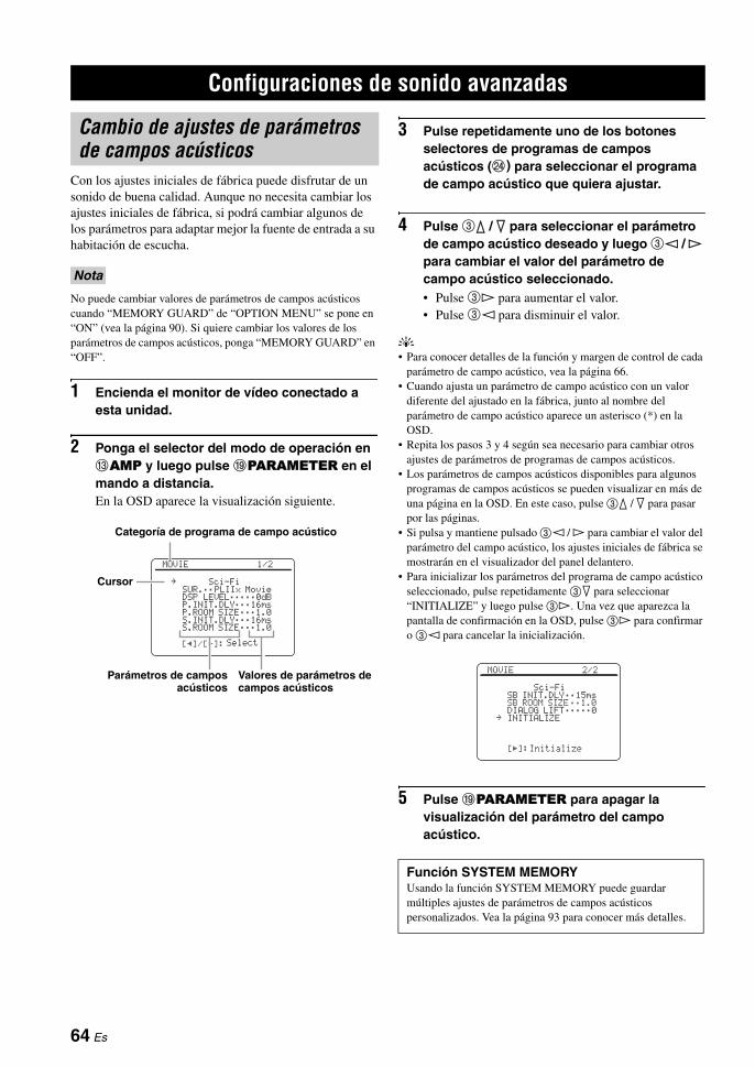
Con los ajustes iniciales de fábrica puede disfrutar de un sonido de buena calidad. Aunque no necesita cambiar los ajustes iniciales de fábrica, si podrá cambiar algunos de los parámetros para adaptar mejor la fuente de entrada a su habitación de escucha.
No puede cambiar valores de parámetros de campos acústicos cuando “MEMORY GUARD” de “OPTION MENU” se pone en “ON” (vea la página 90). Si quiere cambiar los valores de los parámetros de campos acústicos, ponga “MEMORY GUARD” en “OFF”.
1 Encienda el monitor de vídeo conectado a esta unidad.
2 Ponga el selector del modo de operación en CAMP y luego pulse IPARAMETER en el mando a distancia.En la OSD aparece la visualización siguiente.
3 Pulse repetidamente uno de los botones selectores de programas de campos acústicos (N) para seleccionar el programa de campo acústico que quiera ajustar.
4 Pulse 3k / n para seleccionar el parámetro de campo acústico deseado y luego 3l / h para cambiar el valor del parámetro de campo acústico seleccionado.• Pulse 3h para aumentar el valor.• Pulse 3l para disminuir el valor.
y• Para conocer detalles de la función y margen de control de cada
parámetro de campo acústico, vea la página 66.• Cuando ajusta un parámetro de campo acústico con un valor
diferente del ajustado en la fábrica, junto al nombre del parámetro de campo acústico aparece un asterisco (*) en la OSD.
• Repita los pasos 3 y 4 según sea necesario para cambiar otros ajustes de parámetros de programas de campos acústicos.
• Los parámetros de campos acústicos disponibles para algunos programas de campos acústicos se pueden visualizar en más de una página en la OSD. En este caso, pulse 3k / n para pasar por las páginas.
• Si pulsa y mantiene pulsado 3l / h para cambiar el valor del parámetro del campo acústico, los ajustes iniciales de fábrica se mostrarán en el visualizador del panel delantero.
• Para inicializar los parámetros del programa de campo acústico seleccionado, pulse repetidamente 3n para seleccionar “INITIALIZE” y luego pulse 3h. Una vez que aparezca la pantalla de confirmación en la OSD, pulse 3h para confirmar o 3l para cancelar la inicialización.
5 Pulse IPARAMETER para apagar la visualización del parámetro del campo acústico.
Configuraciones de sonido avanzadas
Cambio de ajustes de parámetros de campos acústicos
Nota
Categoría de programa de campo acústico
Parámetros de camposacústicos
Valores de parámetros de campos acústicos
[p]/[[]:
MOVIE 1/2
Sci-FiSUR.;;PLIIx MovieDSP LEVEL;;;;;0dBP.INIT.DLY;;;16msP.ROOM SIZE;;;1.0S.INIT.DLY;;;16msS.ROOM SIZE;;;1.0
Select
.Cursor
Función SYSTEM MEMORYUsando la función SYSTEM MEMORY puede guardar múltiples ajustes de parámetros de campos acústicos personalizados. Vea la página 93 para conocer más detalles.
[[]:
MOVIE 2/2
Sci-FiSB INIT.DLY;;15msSB ROOM SIZE;;1.0DIALOG LIFT;;;;;0INITIALIZE
Initialize
.
64 Es

Configuraciones de sonido avanzadasFU
NC
ION
AM
IENTO
AVA
NZA
DO
Esp
año
l
Configuración básica de los programas de campos acústicos
Cada programa de campo acústico tiene algunos parámetros que definen las características del programa. Para personalizar el programa de campo acústico seleccionado, ajuste primero “DSP LEVEL” y/o “DIALOG LIFT” y luego pruebe con otros parámetros.
yPara cambiar los ajustes de parámetros de los campos acústicos, vea la página 64 para conocer detalles.
Ajuste del nivel del sonido de efectos de los programas de campos acústicos (DSP LEVEL)Los programas de campos acústicos añaden sonidos de efectos (DSP) al sonido de la fuente original para crear campos acústicos en la habitación de escucha. Use el parámetro “DSP LEVEL” para ajustar el nivel de los sonidos de efectos.
Ajuste “DSP LEVEL” de la forma siguiente:
Aumente el valor de “DSP LEVEL” cuando• el sonido de efecto del programa de campo
acústico seleccionado es demasiado bajo.• no puede reconocer ninguna diferencia entre los
programas de campos acústicos.
Disminuya el valor de “DSP LEVEL” cuando• el sonido no es claro.• nota que el efecto de sonido adicional es excesivo.
Margen de control: –6 dB a +3 dB
Ajuste de la posición de diálogo vertical (DIALOG LIFT)Use esta función para ajustar la posición vertical de los diálogos de las películas. La posición ideal de los diálogos está en el centro de la pantalla del monitor de vídeo.
Si los diálogos se oyen en la posición inferior de la pantalla del monitor de vídeo, aumente el valor de “DIALOG LIFT”.
Opciones: 0, 1, 2, 3, 4, 5“0” (ajuste inicial) es la posición más baja, y “5” la más alta.
• “DIALOG LIFT” sólo está disponible cuando “PRESENCE SP” está en “ON” (vea la página 78).
• No puede mover la posición de diálogo más abajo de la posición de diálogo inicial.
El nivel del sonido de efecto DSP está bajo.
El nivel del sonido de efecto DSP está alto.
Notas
La posición de diálogo ideal
Suba la posición de diálogo ideal.
65 Es

Configuraciones de sonido avanzadas
Descripciones de parámetros de campos acústicosPuede ajustar los valores de ciertos parámetros de campos acústicos digitales para que los campos acústicos se recreen con precisión en su habitación de escucha. No todos los parámetros siguientes se encuentran en cada programa.
yPara cambiar los ajustes de parámetros de campos acústicos y adaptarlos a su ambiente de escucha, vea la página 64 para conocer detalles.
Parámetro de campo acústico Características
INIT.DLYP.INIT.DLYS.INIT.DLYSB INIT.DLY
Retardo inicial. Retardo inicial de campo acústico de presencia, surround y surround trasero. Cambia el tamaño aparente del campo acústico ajustando el retardo entre el sonido directo y el primer reflejo oído por el oyente. Cuanto más pequeño sea el valor más pequeño parecerá el campo acústico al oyente.
yCuando ajuste los parámetros de retardo iniciales también le recomendamos ajustar de igual forma los parámetros del tamaño de la habitación correspondientes. Este ajuste es especialmente efectivo para los programas CINEMA DSP.
Margen de control: 1 a 99 ms (INIT.DLY y P.INIT.DLY)1 a 49 ms (S.INIT.DLY y SB INIT.DLY)
Sonido de la fuente
Primeros reflejos
Tiempo Tiempo TiempoRetardo Retardo Retardo
Fuente de sonido
Cara del reflejo
Niv
el
Valor pequeño = 1 ms Valor grande = 99 ms
Niv
el
Niv
el
66 Es
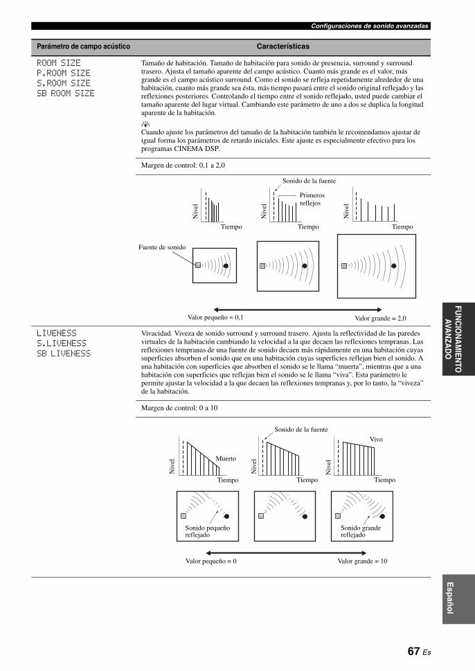
Configuraciones de sonido avanzadasFU
NC
ION
AM
IENTO
AVA
NZA
DO
Esp
año
l
ROOM SIZEP.ROOM SIZES.ROOM SIZESB ROOM SIZE
Tamaño de habitación. Tamaño de habitación para sonido de presencia, surround y surround trasero. Ajusta el tamaño aparente del campo acústico. Cuanto más grande es el valor, más grande es el campo acústico surround. Como el sonido se refleja repetidamente alrededor de una habitación, cuanto más grande sea ésta, más tiempo pasará entre el sonido original reflejado y las reflexiones posteriores. Controlando el tiempo entre el sonido reflejado, usted puede cambiar el tamaño aparente del lugar virtual. Cambiando este parámetro de uno a dos se duplica la longitud aparente de la habitación.
yCuando ajuste los parámetros del tamaño de la habitación también le recomendamos ajustar de igual forma los parámetros de retardo iniciales. Este ajuste es especialmente efectivo para los programas CINEMA DSP.
Margen de control: 0,1 a 2,0
LIVENESSS.LIVENESSSB LIVENESS
Vivacidad. Viveza de sonido surround y surround trasero. Ajusta la reflectividad de las paredes virtuales de la habitación cambiando la velocidad a la que decaen las reflexiones tempranas. Las reflexiones tempranas de una fuente de sonido decaen más rápidamente en una habitación cuyas superficies absorben el sonido que en una habitación cuyas superficies reflejan bien el sonido. A una habitación con superficies que absorben el sonido se le llama “muerta”, mientras que a una habitación con superficies que reflejan bien el sonido se le llama “viva”. Esta parámetro le permite ajustar la velocidad a la que decaen las reflexiones tempranas y, por lo tanto, la “viveza” de la habitación.
Margen de control: 0 a 10
Parámetro de campo acústico Características
Niv
el
Niv
el
Niv
el
Tiempo Tiempo Tiempo
Sonido de la fuente
Primeros reflejos
Valor pequeño = 0,1 Valor grande = 2,0
Fuente de sonido
Sonido de la fuente
Niv
el
Niv
el
Niv
el
Muerto
Vivo
Tiempo Tiempo Tiempo
Sonido pequeño reflejado
Sonido grande reflejado
Valor pequeño = 0 Valor grande = 10
67 Es

Configuraciones de sonido avanzadas
REV.TIME Tiempo de reverberación. Ajusta el tiempo que tarda en decaer el sonido de reverberación denso posterior unos 60 dB a 1 kHz. Esto cambia el tamaño aparente del entorno acústico en una gama sumamente amplia. Establece un tiempo de reberveración más largo para obtener un sonido de reverberación más sostenido, y un tiempo más corto para obtener un sonido articulado.
Margen de control: 1,0 a 5,0 s
REV.DELAY Retardo de reverberación. Ajusta la diferencia de tiempo entre el comienzo del sonido directo y el comienzo del sonido de reverberación. Cuanto más grande es el valor, más tarde empieza el sonido de reverberación. Un sonido de reverberación tardío hace que usted se sienta como si estuviera en un ambiente acústico grande.
Margen de control: 0 a 250 ms
REV.LEVEL Nivel de reverberación. Ajusta el volumen del sonido de reverberación. Cuanto más grande es el valor, más fuerte se hace la reverberación.
Margen de control: 0 a 100%
Parámetro de campo acústico Características
Reverberación ReverberaciónSonido de la fuente
REV.TIME REV.TIME REV.TIMEFuente de sonido
Reverberación corta Reverberación larga
Valor pequeño = 1,0 s Valor grande = 5,0 s
Primeros reflejos
60 dB 60 dB 60 dB
(dB)
Niv
el Sonido de la fuente
Reverberación
REV.TIMEREV.DELAY
Tiempo
60 dB
Sonido de la fuente
Niv
el
REV. LEVEL
Tiempo
68 Es

Configuraciones de sonido avanzadasFU
NC
ION
AM
IENTO
AVA
NZA
DO
Esp
año
l
Selección de decodificadores para fuentes de 2 canales (modo de decodificador surround)
Use esta función para reproducir fuentes con los decodificadores seleccionados. Puede reproducir fuentes de 2 canales o múltiples canales.
Ponga el selector del modo de operación en CAMP y luego pulse repetidamente KSUR. DECODE en el mando a distancia para seleccionar el modo de decodificador surround.
Puede seleccionar el modo de decodificador surround deseado dependiendo del tipo de fuente que esté reproduciendo y sus preferencias personales.
yPuede cambiar los ajustes de parámetros del decodificador. Pulse IPARAMETER y luego pulse repetidamente 3k / n el mando a distancia para seleccionar el parámetro de decodificador deseado. Puede cambiar el valor del parámetro seleccionado pulsando repetidamente 3l / h en el mando a distancia.
Parámetro de campo acústico Características
DIRECT(“2ch Stereo” solamente)
Estéreo directo de 2 canales. Omite los decodificadores y los procesadores DSP de esta unidad para obtener un sonido hi-fi puro cuando se reproducen fuentes analógicas de 2 canales.
Opciones: AUTO, OFF
y• Seleccione “AUTO” para omitir los decodificadores, los procesadores DSP y la circuitería de control
de sólo cuando “BASS” y “TREBLE” estén en to 0 dB (vea la página 52).• Seleccione “OFF” para no omitir los decodificadores, los procesadores DSP y la circuitería de control
de sólo cuando “BASS” y “TREBLE” estén en to 0 dB.• Cuando se introducen señales de múltiples canales, éstas se mezclan en 2 canales y salen por los
altavoces delanteros derecho e izquierdo.• Las señales de baja frecuencia de los canales delanteros izquierdo y derecho se redirigen al altavoz de
subgraves en los casos siguientes:– “LFE/BASS OUT” está en “BOTH” (vea la página 77).– “FRONT SP” está en “SMALL” (vea la página 77) y “LFE/BASS OUT” está en “SWFR”
(vea la página 77).
CT LEVELSL LEVELSR LEVELSB LEVELPL LEVELPR LEVEL(“7ch Stereo” solamente)
Niveles de altavoz central, surround izquierdo, surround derecho, surround trasero, presencia izquierdo y presencia derecho para modo estéreo de 7 canales. Ajusta el nivel del sonido para cada canal en el modo estéreo de 7 canales.
Margen de control: 0 a 100%
EFFECT LEVEL(“Straight Enhancer” y “7ch Enhancer” solamente)
Nivel de efecto directo y de 7 canales Compressed Music Enhancer. Las señales de alta frecuencia de algunas fuentes pueden realzarse demasiado. En este caso, ajuste el nivel de efecto en “LOW”.
Opciones: HIGH, LOW
• Seleccione “HIGH” para un nivel de efecto alto.• Seleccione “LOW” para un nivel de efecto bajo.
Selección de decodificadores
69 Es

Configuraciones de sonido avanzadas
Dscripciones del decodificador
yCuando seleccione el modo de decodificador surround para fuentes digitales multicanales, esta unidad seleccionará automáticamente el decodificador correspondiente para cada fuente.
SUR. DECODESur. Decode
PRO LOGIC
Procesamiento Dolby Pro Logic para cualquier fuente.
SUR. DECODESur. Decode
PLIIx MoviePLII Movie
Procesamiento Dolby Pro Logic IIx (o Dolby Pro Logic II) para fuentes de cine. El decodificador Pro Logic IIx no está disponible cuando “SUR.B L/R SP” se pone en “NONE” (vea la página 78).
SUR. DECODESur. Decode
PLIIx MusicPLII Music
Procesamiento Dolby Pro Logic IIx (o Dolby Pro Logic II) para fuentes de música. El decodificador Pro Logic IIx no está disponible cuando “SUR.B L/R SP” se pone en “NONE” (vea la página 78).
PANORAMA DIMENSION CENTER WIDTH
SUR. DECODESur. Decode
PLIIx GamePLII Game
Procesamiento Dolby Pro Logic IIx (o Dolby Pro Logic II) para fuentes de juegos. El decodificador Pro Logic IIx no está disponible cuando “SUR.B L/R SP” se pone en “NONE” (vea la página 78).
CENTER WIDTHDIMENSION
PLIIMusic
PLIIxMusicSUR. DECODE
Sur. Decode
PANORAMA
+10
SUR.DECODE
Procesamiento Dolby Pro Logic IIx (o Dolby Pro Logic II) para fuentes de música. El decodificador Pro Logic IIx no está disponible cuando “SUR.B L/R SP” se pone en “NONE” (vea la página 78).
Parámetros de decodificador disponibles (vea la página 71) Descripción del programa
Botón de mando a distancia
Nombre del decodificador (SUR.)
Categoría y nombre del programa
+10
SUR.DECODE
+10
SUR.DECODE
+10
SUR.DECODE
+10
SUR.DECODE
SUR. DECODESur. Decode
Neo:6 Cinema
Procesamiento DTS para fuentes de películas.
+10
SUR.DECODE
SUR. DECODESur. Decode
Neo:6 Music
Procesamiento DTS para fuentes de música.
C. IMAGE
+10
SUR.DECODE
70 Es

Configuraciones de sonido avanzadasFU
NC
ION
AM
IENTO
AVA
NZA
DO
Esp
año
l
Descripciones de parámetros del decodificador
Selección de decodificadores usados con programas de campos acústicos (SUR.)
Use esta función para seleccionar el decodificador deseado usado con los programas de campos acústicos MOVIE (excepto “Mono Movie”). Vea la página 49 para conocer detalles del programa de campo acústivo MOVIE.
Decodificadores disponibles
Parámetros de decodificador Características
PANORAMA(“PLIIx Music” y “PLII Music” solamente)
Panorama Pro Logic IIx Music y Pro Logic II Music. Envía señales estéreo a los altavoces surround y a los altavoces delanteros para proporcionar un efecto envolvente.
Opciones: OFF, ON
DIMENSION(“PLIIx Music” y “PLII Music” solamente)
Dimensión Pro Logic IIx Music y Pro Logic II Music. Ajusta el campo acústico hacia la parte delantera o trasera.
Margen de control: –3 (hacia atrás) a +3 (hacia delante)
Ajuste inicial: STD (estándar)
CENTER WIDTH(“PLIIx Music” y “PLII Music” solamente)
Anchura central Pro Logic IIx Music y Pro Logic II Music. Mueve la salida del canal central completamente hacia el altavoz central o hacia los altavoces delanteros derecho e izquierdo. Un valor grande mueve la salida del canal central hacia los altavoces delanteros derecho e izquierdo.
Margen de control: 0 (el sonido del canal central sale solamente por el altavoz central) a 7 (el sonido del canal central sale solamente por los altavoces delanteros derecho e izquierdo)
Ajuste inicial: 3
C.IMAGE(“Neo:6 Music” solamente)
Imagen central DTS Neo:6 Music. Ajusta la salida de los canales delanteros derecho e izquierdo con relación al canal central para que éste domine más o menos según sea necesario.
Margen de control: 0,0 (el sonido del canal dentral sale solamente por los altavoces delanteros derecho e izquierdo) a1,0 (el sonido del canal central sale solamente por el altavoz central)
Ajuste inicial: 0.3
Decodificador Funciones
PLIIx MoviePLII Movie
Procesamiento Dolby Pro Logic IIx (o Dolby Pro Logic II) para fuentes de cine. El decodificador Pro Logic IIx no está disponible cuando “SUR.B L/R SP” se pone en “NONE” (vea la página 78).
Neo:6 Cinema Procesamiento DTS para fuentes de películas
71 Es

Para realizar una variedad de ajustes del sistema y personalizar el funcionamiento de esta unidad puede utilizar los parámetros siguientes en “SET MENU”. Cambie los ajustes iniciales (en negrita debajo de cada parámetro) para reflejar las necesidades de su ambiente de escucha.
Ajuste automático AUTO SETUP
Use esta función para ajustar automáticamente los altavoces y los parámetros del sistema (vea la página 37).
Ajuste manual MANUAL SETUP
Use esta función para ajustar manualmente los altavoces y los parámetros del sistema.
Menú básico 1 BASIC MENU
Personalización de esta unidad (MANUAL SETUP)
Menú Parámetro Funciones Página
A)SPEAKER SET LFE/BASS OUT Selecciona los altavoces que dan salida al LFE (efecto de baja frecuencia) y a las señales de baja frecuencia.
77
FRONT SP Selecciona el tamaño de los altavoces delanteros. 77
CENTER SP Selecciona el tamaño del altavoz central. 77
SUR. L/R SP Selecciona el tamaño y el número de los altavoces surround. 78
SUR.B L/R SP Selecciona el tamaño y el número de los altavoces surround traseros. 78
PRESENCE SP Selecciona si esta unidad utiliza los altavoces de presencia. 78
CROSS OVER Selecciona la frecuencia de cruce de todos los altavoces puestos en “SML” (o “SMALL”) o en “NONE” en “SPEAKER SET” (vea las páginas 77 y 78).
78
SUBWOOFER PHASE Cambia la fase de su altavoz de subgraves si el sonido grave no es suficiente o no suena claro.
79
PRIORITY Da prioridad a los altavoces de presencia o surround traseros cuando reproduce fuentes que contienen señales de canales surround traseros usando los programas de campos acústicos CINEMA DSP.
79
B)SPEAKER LEVEL FR.L/FR.R/CENT./SUR.L/SUR.R/SB L/SB R/SWFR/PR.L/PR.R
Ajusta el balance de los niveles de los altavoces entre los altavoces delantero izquierdo o surround izquierdo y cada altavoz seleccionado en “SPEAKER SET” (vea la página 77).
79
C)SP DISTANCE UNIT Selecciona la unidad para ajustar la distancia de los altavoces. 80
FRONT L/FRONT R/CENTER/SUR. L/SUR. R/SB L/SB R/SWFR/PRNS L/PRNS R
Ajusta la distancia de cada altavoz y el retardo aplicado al canal respectivo.
80
D)TEST TONE — Activa o desactiva la salida del tono de prueba para los ajustes “SPEAKER SET”, “SPEAKER LEVEL” y “SP DISTANCE”.
80
72 Es

Personalización de esta unidad (MANUAL SETUP)FU
NC
ION
AM
IENTO
AVA
NZA
DO
Esp
año
l
Menú de volumen 2 VOLUME MENU
Menú de sonido 3 SOUND MENU
Parámetro Funciones Página
ADAPTIVE DRC Selecciona si esta unidad ajusta automáticamente la gama dinámica en conjunción con el nivel del sonido o no.
81
ADAPTIVE DSP LEVEL Selecciona si esta unidad ajusta automáticamente el nivel de efectos de DSP en conjunción con el nivel del sonido o no.
81
MUTING TYPE Ajusta cuánto reduce la función de silenciamiento el volumen de salida (vea la página 44). 81
MAX VOL. Ajusta el nivel de sonido máximo de la zona principal. 81
INIT. VOL. Ajusta el nivel del sonido de la zona principal cuando se conecta la alimentación de esta unidad.
81
Menú Parámetro Funciones Página
A)EQUALIZER EQ TYPE SELECT Selecciona el tipo de ecualizador. 82
GEQ Ajusta la calidad tonal de los altavoces cuando usted pone “EQ TYPE SELECT” en “GEQ”.
82
TEST Selecciona si esta unidad va a dar salida o no al tono de prueba mientras se hacen los ajustes de “GEQ”.
82
B)LFE LEVEL SPEAKER Ajusta el nivel LFE de los altavoces. 83
HEADPHONE Ajusta el nivel LFE de los auriculares. 83
C)DYNAMIC RANGE SPEAKER Ajusta la cantidad de compresión de gama dinámica de los altavoces. 83
HEADPHONE Ajusta la cantidad de compresión de gama dinámica de los auriculares. 83
D)LIPSYNC HDMI AUTO Selecciona si esta unidad va a activar o no la función de sincronización automática de audio y vídeo (sincronización automática de voz).
84
AUTO DELAY Hace ajustes finos del retardo de audio cuando está activada la función de sincronización automática de audio y vídeo.
84
MANUAL DELAY Ajuste manual del retardo de audio cuando el monitor de vídeo conectado no es compatible con la función de sincronización automática de audio y vídeo o “HDMI AUTO” está en “OFF”.
84
E)AUDIO SET EXTD SUR. Use esta función para disfrutar de la reproduccion de 6.1/7.1 canales de fuentes de múltiples canales utilizando los decodificadores Dolby Pro Logic IIx, Dolby Digital EX o DTS-ES con los altavoces surround traseros conectados.
84
TONE BYPASS Selecciona si la salida de audio va a omitir el circuito de control de tono cuando “TREBLE” y “BASS” se ponen en 0 dB (vea la página 52).
84
F)HDMI SET SUPPORT AUDIO Selecciona si se van a reproducir señales de audio HDMI en esta unidad o en otro componente HDMI conectado al jack HDMI OUT.
85
73 Es
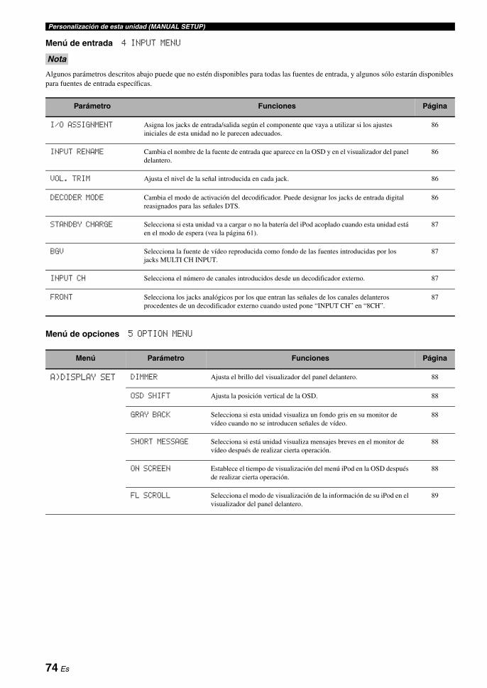
Personalización de esta unidad (MANUAL SETUP)
Menú de entrada 4 INPUT MENU
Algunos parámetros descritos abajo puede que no estén disponibles para todas las fuentes de entrada, y algunos sólo estarán disponibles para fuentes de entrada específicas.
Menú de opciones 5 OPTION MENU
Nota
Parámetro Funciones Página
I/O ASSIGNMENT Asigna los jacks de entrada/salida según el componente que vaya a utilizar si los ajustes iniciales de esta unidad no le parecen adecuados.
86
INPUT RENAME Cambia el nombre de la fuente de entrada que aparece en la OSD y en el visualizador del panel delantero.
86
VOL. TRIM Ajusta el nivel de la señal introducida en cada jack. 86
DECODER MODE Cambia el modo de activación del decodificador. Puede designar los jacks de entrada digital reasignados para las señales DTS.
86
STANDBY CHARGE Selecciona si esta unidad va a cargar o no la batería del iPod acoplado cuando esta unidad está en el modo de espera (vea la página 61).
87
BGV Selecciona la fuente de vídeo reproducida como fondo de las fuentes introducidas por los jacks MULTI CH INPUT.
87
INPUT CH Selecciona el número de canales introducidos desde un decodificador externo. 87
FRONT Selecciona los jacks analógicos por los que entran las señales de los canales delanteros procedentes de un decodificador externo cuando usted pone “INPUT CH” en “8CH”.
87
Menú Parámetro Funciones Página
A)DISPLAY SET DIMMER Ajusta el brillo del visualizador del panel delantero. 88
OSD SHIFT Ajusta la posición vertical de la OSD. 88
GRAY BACK Selecciona si esta unidad visualiza un fondo gris en su monitor de vídeo cuando no se introducen señales de vídeo.
88
SHORT MESSAGE Selecciona si está unidad visualiza mensajes breves en el monitor de vídeo después de realizar cierta operación.
88
ON SCREEN Establece el tiempo de visualización del menú iPod en la OSD después de realizar cierta operación.
88
FL SCROLL Selecciona el modo de visualización de la información de su iPod en el visualizador del panel delantero.
89
74 Es
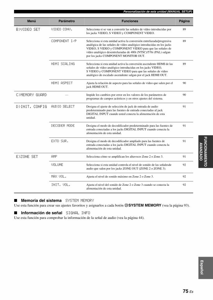
Personalización de esta unidad (MANUAL SETUP)FU
NC
ION
AM
IENTO
AVA
NZA
DO
Esp
año
l
Memoria del sistema SYSTEM MEMORY
Use esta función para crear sus ajustes favoritos y asignarlos a cada botón MSYSTEM MEMORY (vea la página 93).
Información de señal SIGNAL INFO
Use esta función para comprobar la información de la señal de audio (vea la página 44).
B)VIDEO SET VIDEO CONV. Selecciona si se van a convertir las señales de vídeo introducidas por los jacks VIDEO, S VIDEO y COMPONENT VIDEO.
89
COMPONENT I/P Selecciona si esta unidad activa la conversión entrelazada/progresiva analógica de las señales de vídeo analógico introducidas en los jacks VIDEO, S VIDEO y COMPONENT VIDEO para que las señales de vídeo analógico desentrelazadas de 480i (NTSC)/576i (PAL) salgan por los jacks COMPONENT MONITOR OUT.
89
HDMI SCALING Selecciona si esta unidad activa la conversión ascendente HDMI de las señales de vídeo analógico introducidas en los jacks VIDEO, S VIDEO y COMPONENT VIDEO para que las señales de vídeo analógico de escalado ascendente salgan por el jack HDMI OUT.
89
HDMI ASPECT Ajusta la relación de aspecto para las señales de vídeo que salen por el jack HDMI OUT.
90
C)MEMORY GUARD — Impide los cambios por error en los valores de los parámetros de programas de campos acústicos y en otros ajustes del sistema.
90
D)INIT. CONFIG AUDIO SELECT Designa el ajuste de selección de jack de entrada de audio predeterminado para las fuentes de entrada conectadas al jack DIGITAL INPUT cuando usted conecta la alimentación de esta unidad.
91
DECODER MODE Designa el modo de decodificador predeterminado para las fuentes de entrada conectadas a los jacks DIGITAL INPUT cuando conecta la alimentación de esta unidad.
91
EXTD SUR. Designa el modo de decodificador ampliado para las fuentes de entrada conectadas a los jacks DIGITAL INPUT cuando conecta la alimentación de esta unidad.
91
E)ZONE SET AMP Selecciona cómo se amplifican los altavoces Zone 2 o Zone 3. 91
VOLUME Selecciona si esta unidad controla el nivel de sonido de las señalesde audio que salen por los jacks ZONE OUT (ZONE 2 o ZONE 3).
92
MAX VOL. Ajusta el nivel de sonido máximo en Zone 2 o Zone 3. 92
INIT. VOL. Ajusta el nivel del sonido de Zone 2 o Zone 3 cuando se conecta la alimentación de esta unidad.
92
Menú Parámetro Funciones Página
75 Es
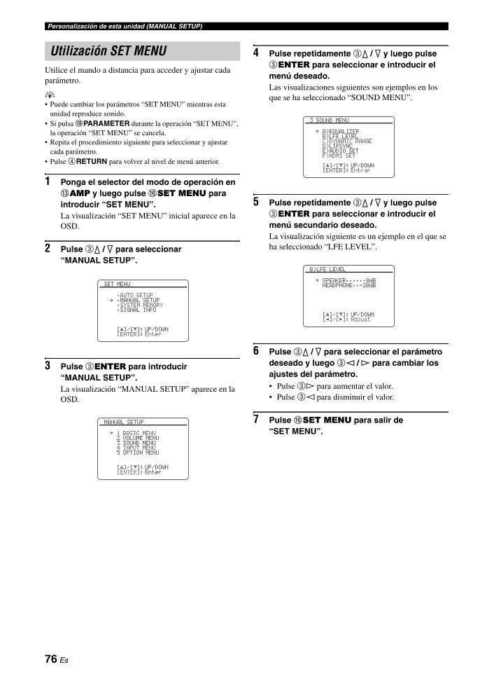
Personalización de esta unidad (MANUAL SETUP)
Utilice el mando a distancia para acceder y ajustar cada parámetro.
y• Puede cambiar los parámetros “SET MENU” mientras esta
unidad reproduce sonido.• Si pulsa IPARAMETER durante la operación “SET MENU”,
la operación “SET MENU” se cancela.• Repita el procedimiento siguiente para seleccionar y ajustar
cada parámetro.• Pulse 4RETURN para volver al nivel de menú anterior.
1 Ponga el selector del modo de operación en CAMP y luego pulse FSET MENU para introducir “SET MENU”.La visualización “SET MENU” inicial aparece en la OSD.
2 Pulse 3k / n para seleccionar “MANUAL SETUP”.
3 Pulse 3ENTER para introducir “MANUAL SETUP”.La visualización “MANUAL SETUP” aparece en la OSD.
4 Pulse repetidamente 3k / n y luego pulse 3ENTER para seleccionar e introducir el menú deseado.Las visualizaciones siguientes son ejemplos en los que se ha seleccionado “SOUND MENU”.
5 Pulse repetidamente 3k / n y luego pulse 3ENTER para seleccionar e introducir el menú secundario deseado.La visualización siguiente es un ejemplo en el que se ha seleccionado “LFE LEVEL”.
6 Pulse 3k / n para seleccionar el parámetro deseado y luego 3l / h para cambiar los ajustes del parámetro.• Pulse 3h para aumentar el valor.• Pulse 3l para disminuir el valor.
7 Pulse FSET MENU para salir de “SET MENU”.
Utilización SET MENU
[]/[]:[ENTER]:
[ p
SET MENU
;AUTO SETUP;MANUAL SETUP;SYSTEM MEMORY;SIGNAL INFO
UP/DOWNEnter
.
[]/[]:[ENTER]:
[ p
MANUAL SETUP
1 BASIC MENU2 VOLUME MENU3 SOUND MENU4 INPUT MENU5 OPTION MENU
UP/DOWNEnter
.
[]/[]:[ENTER]:
[ p
3 SOUND MENU
A)EQUALIZERB)LFE LEVELC)DYNAMIC RANGED)LIPSYNCE)AUDIO SETF)HDMI SET
UP/DOWNEntrar
.
[]/[]:[p]/[[]:
[ p
B)LFE LEVEL
SPEAKER;;;;;;0dBHEADPHONE;;-20dB
UP/DOWNAdjust
.
76 Es

Personalización de esta unidad (MANUAL SETUP)FU
NC
ION
AM
IENTO
AVA
NZA
DO
Esp
año
l
Use esta función para establecer manualmente los ajustes básicos de los altavoces. La mayoría de los parámetros “BASIC MENU” se ajusta automáticamente cuando se ejecuta el ajuste automático.
yPonga “TEST TONE” en “ON” para dar salida al tono de prueba para “SPEAKER SET”, “SPEAKER LEVEL” y “SP DISTANCE”.
Ajustes de altavoces A)SPEAKER SET
Salida de LFE/graves LFE/BASS OUT
Use esta función para seleccionar los altavoces que dan salida al LFE (efecto de baja frecuencia) y a las señales de baja frecuencia.Opciones: SWFR, FRONT, BOTH
Cuando una altavoz de subgraves está conectado a esta unidad y usted quiere obtener un sonido de graves natural:Seleccione “SWFR” (altavoz de subgraves). Las señales LFE, así como también las señales de baja frecuencia de otros altavoces puestos en “SML” (o “SMALL”), se dirigen al altavoz de subgraves.
Cuando una altavoz de subgraves está conectado a esta unidad y usted quiere obtener un sonido de graves profundo:Seleccione “BOTH” (ambos) Las señales de baja frecuencia de cualquier fuente salen por el altavoz de subgraves. Las señales LFE, así como también las señales de baja frecuencia de otros altavoces puestos en “SML” (o “SMALL”), se dirigen al altavoz de subgraves. Las señales de baja frecuencia de los canales delantero derecho e izquierdo se dirigen a los altavoces delanteros derecho e izquierdo y al altavoz de subgraves independientemente del ajuste “FRONT SP”.
Cuando no use un altavoz de subgraves:Seleccione “FRONT” (delantero). Las señales LFE, las señales de baja frecuencia de los canales delanteros derecho e izquierdo y las señales de baja frecuencia de otros altavoces puestos en “SML” (o “SMALL”) se dirigen todas a los altavoces delanteros derecho e izquierdo independientemente del ajuste “FRONT SP”.
Altavoces delanteros FRONT SP
Opciones: SMALL, LARGE
Cuando los altavoces delanteros son grandes:Seleccione “LARGE” (grande).
Cuando los altavoces delanteros son pequeños:Seleccione “SMALL” (pequeño).
• Cuando “LFE/BASS OUT” se pone en “FRONT”, las señales LFE encontradas en las fuentes de series de bits, las señales de baja frecuencia de los canales delanteros derecho e izquierdo y las señales de baja frecuencia de otros altavoces puestos en “SML” (o “SMALL”) se dirigen todas a los altavoces delanteros derecho e izquierdo independientemente del ajuste “FRONT SP”.
• Cuando “LFE/BASS OUT” se ponga en “FRONT”, usted sólo podrá seleccionar “LARGE” en “FRONT SP”. Si el valor de “FRONT SP” se pone de antemano en otro ajuste que no sea “LARGE”, esta unidad cambiará automáticamente el valor a “LARGE”.
Altavoz central CENTER SP
Opciones: NONE, SMALL, LARGE
Cuando el altavoz central es grande:Seleccione “LARGE” (grande).
Cuando el altavoz central es pequeño:Seleccione “SMALL” (pequeño).
Cuando no use el altavoz central:Seleccione “NONE” (ninguno). Las señales del canal central se dirigen a los altavoces delanteros derecho e izquierdo.
1 BASIC MENU
[]/[]:[ENTER]:
[ p1 BASIC MENU
A)SPEAKER SETB)SPEAKER LEVELC)SP DISTANCED)TEST TONE
UP/DOWNEnter
.
A)SPEAKER SET
LFE/BASS OUT
SWFR FRONT>BOTH
Medida para el tamaño de altavocesLa sección del altavoz de graves de un altavoz es
– 16 cm o más grande– inferior a 16 cm: pequeño
Notas
A)SPEAKER SET
FRONT SP
SMALL >LARGE
A)SPEAKER SET
CENTER SP
NONE >SMALL LARGE
77 Es

Personalización de esta unidad (MANUAL SETUP)
Altavoces surround derecho/izquierdo SUR. L/R SP
Opciones: NONE, SMALL, LARGE
Cuando los altavoces surround son grandes:Seleccione “LARGE” (grande).
Cuando los altavoces surround son pequeños:Seleccione “SMALL” (pequeño).
Cuando no use los altavoces surround:Seleccione “NONE” (ninguno). Esta unidad se pone en el modo Virtual CINEMA DSP (vea la página 51) y “SUR.B L/R SP” se pone automáticamente en “NONE”.
yVea la página 17 para la información de conexión de los altavoces surround traseros.
Altavoces surround traseros derecho/izquierdoSUR.B L/R SP
Opciones: NONE, SMLx1, SMLx2, LRGx1, LRGx2
Cuando los altavoces surround traseros derecho e izquierdo son grandes:Seleccione “LRGx2” (grande x 2).
Cuando el altavoz surround trasero único es grande:Seleccione “LRGx1” (grande x 1).
Cuando los altavoces surround traseros derecho e izquierdo son pequeñosSeleccione “SMLx2” (pequeño x 2).
Cuando el altavoz surround trasero único es pequeño:Seleccione “SMLx1” (pequeño x 1).
Cuando no use los altavoces surround traseros:Seleccione “NONE” (ninguno). Las señales de los canales surround traseros se dirigen a los altavoces surround derecho e izquierdo.
yVea la página 17 para la información de conexión de los altavoces surround traseros.
Si se introducen señales de audio Dolby TrueHD y “SUR.B L/R SP” se pone en “NONE”, los canales surround traseros derecho e izquierdo no se dirigen a los altavoces surround derecho e izquierdo.
Altavoces de presencia PRESENCE SP
Utilice esta función si quiere usar los altavoces de presencia conectados a esta unidad.Opción: NONE, YES
Cuando no use los altavoces de presencia:Seleccione “NONE” (ninguno).
Cuando use los altavoces de presencia:Seleccione “YES” (sí).
“DIALOG LIFT” sólo está disponible cuando “PRESENCE SP” está en “YES”.
Transición de graves CROSS OVER
Use esta función para seleccionar la frecuencia de cruce de todos los altavoces puestos en “SML” (o “SMALL”) o en “NONE” en “SPEAKER SET” (vea la página 77). Todas las frecuencias por debajo de la seleccionada se enviarán al altavoz de subgraves o a los altavoces puestos en “LRG” (o “LARGE”) en “SPEAKER SET” (vea la página 77).Opciones: 40Hz, 60Hz, 80Hz, 90Hz, 100Hz, 110Hz,
120Hz, 160Hz, 200Hz
ySi su altavoz de subgraves puede ajustar el volumen de salida y la frecuencia de cruce, ajuste el volumen a la mitad (o un poco menso) y ajuste la frecuencia de cruce al máximo.
Medida para el tamaño de altavocesLa sección del altavoz de graves de un altavoz es
– 16 cm o más grande– inferior a 16 cm: pequeño
A)SPEAKER SET
SUR. L/R SP
NONE >SMALL LARGE
A)SPEAKER SET
SUR.B L/R SP
NONE SMLx1 >SMLx2
Notas
Nota
A)SPEAKER SET
PRESENCE SP
NONE >YES
A)SPEAKER SET
CROSS OVER
FREQ;;;;80Hz
78 Es

Personalización de esta unidad (MANUAL SETUP)FU
NC
ION
AM
IENTO
AVA
NZA
DO
Esp
año
l
Fase de subgraves SUBWOOFER PHASE
Use esta función para cambiar la fase de su altavoz de subgraves si el sonido grave no es suficiente o no suena claro.
Prioridad del canal de presencia/surround trasero PRIORITY
Use esta función para dar prioridad a los altavoces de presencia o surround traseros cuando reproduce fuentes de audio de 2 canales usando los programas de campos acústicos.
yPara conocer detalles de la salida de sonido de cada altavoz en los programas de campo acústico, consulte “Salida de sonido en cada programa de campo acústico” en “APPENDIX” al final de este manual.
Nivel de altavoces B)SPEAKER LEVEL
Utilice esta función para balancear manualmente los niveles de los altavoces entre los altavoces delantero izquierdo o surround izquierdo y cada altavoz seleccionado en “SPEAKER SET” (vea la página 77).Margen de control: –10,0 dB a +10,0 dBPaso de control: 0,5 dBAjuste inicial:FR.L/FR.R/SWFR/PR.L/PR.R: 0 dBCENT./SUR.L/SUR.R/SB L/SB R: –1,0 dB
y• Si su altavoz de subgraves puede ajustar el volumen de salida y
la frecuencia de cruce, ajuste el volumen a la mitad (o un poco menso) y ajuste la frecuencia de cruce al máximo.
• Ponga “TEST TONE” en “ON” para dar salida al tono de prueba para el ajuste “SPEAKER LEVEL” (vea la página 80).
• Los canales de altavoces disponibles son distintos según el ajuste de los altavoces.
• En lugar de “SB L” y “SB R” se visualiza “SB” si “SUR. B L/R SP” se pone en “SMLx1” o “LRGx1” (vea la página 78).
Opción Funciones
NORMAL(normal)
No cambie la fase de su altavoz de subgraves.
REVERSE(invertir)
Seleccione la inversión de fase de su altavoz de subgraves.
Opción Funciones
PRNS Usa los altavoces de presencia.
SUR.B Usa los altavoces surround traseros.
A)SPEAKER SET
SUBWOOFER PHASE
>NORMAL REVERSE
A)SPEAKER SET
PRIORITY
PRNS >SUR.B
SPEAKER LEVEL Altavoz ajustado
FR.L Altavoz delantero izquierdo
FR.R Altavoz delantero derecho
CENT. Altavoz central
SUR.L Altavoz surround izquierdo
SUR.R Altavoz surround derecho
SB L Altavoz surround trasero izquierdo
SB R Altavoz surround trasero derecho
SWFR Altavoz de subgraves
PR.L Altavoz izquierdo de presencia
PR.R Altavoz derecho de presencia
Notas
B)SPEAKER LEVEL 1/2
FR.LFR.RCENT.SUR.LSUR.R
.
B)SPEAKER LEVEL 2/2
SB LSB RSWFRPR.LPR.R
.
79 Es
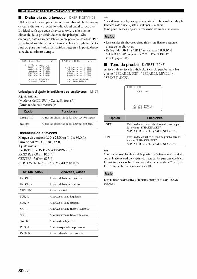
Personalización de esta unidad (MANUAL SETUP)
Distancia de altavoces C)SP DISTANCE
Utilice esta función para ajustar manualmente la distancia de cada altavoz y el retardo aplicado al canal respectivo. Lo ideal sería que cada altavoz estuviese a la misma distancia de la posición de escucha principal. Sin embargo, esto es imposible en la mayoría de las casas. Por lo tanto, al sonido de cada altavoz se le debe aplicar cierto retardo para que todos los sonidos lleguen a la posición de escucha al mismo tiempo.
Unidad para el ajuste de la distancia de los altavoces UNIT
Ajuste inicial:[Modelos de EE.UU. y Canadá]: feet (ft)[Otros modelos]: meters (m)
Distancias de altavocesMargen de control: 0,30 a 24,00 m (1.0 a 80.0 ft)Paso de control: 0,10 m (0.5 ft)Ajuste inicial:FRONT L/FRONT R/SWFR/PRNS L/PRNS R: 3,00 m (10.0 ft)CENTER: 2,60 m (8.5 ft)SUR. L/SUR. R/SB L/SB R: 2,40 m (8.0 ft)
ySi su altavoz de subgraves puede ajustar el volumen de salida y la frecuencia de cruce, ajuste el volumen a la mitad (o un poco menso) y ajuste la frecuencia de cruce al máximo.
• Los canales de altavoces disponibles son distintos según el ajuste de los altavoces.
• En lugar de “SB L” y “SB R” se visualiza “SUR.B” si “SUR.B L/R SP” se pone en “SMLx1” o “LRGx1” (vea la página 78).
Tono de prueba D)TEST TONE
Activa o desactiva la salida del tono de prueba para los ajustes “SPEAKER SET”, “SPEAKER LEVEL” y “SP DISTANCE”.
ySi utliza un medidor de nivel de presión acústica manual, sujételo con el brazo extendido y apúntelo hacia arriba para que quede en la posición de escucha. Con el medidor en la escala de 70 dB y en C SLOW, calibre cada altavoz a 75 dB.
Esta función se desactiva automáticamente si sale de “BASIC MENU”.
Opción Funciones
meters (m) Ajusta las distancias de los altavoces en metros.
feet (ft) Ajusta las distancias de los altavoces en pies.
SP DISTANCE Altavoz ajustado
FRONT L Altavoz delantero izquierdo
FRONT R Altavoz delantero derecho
CENTER Altavoz central
SUR. L Altavoz surround izquierdo
SUR. R Altavoz surround derecho
SB L Altavoz surround trasero izquierdo
SB R Altavoz surround trasero derecho
SWFR Altavoz de subgraves
PRNS L Altavoz izquierdo de presencia
PRNS R Altavoz derecho de presencia
[]/[]:[p]/[[]:
[ p
C)SP DISTANCE 2/2
SB L;;;;;;;;2.40mSB R;;;;;;;;2.40mSWFR;;;;;;;;3.00mPRNS L;;;;;;3.00mPRNS R;;;;;;3.00m
UP/DOWNAdjust
.
[]/[]:[p]/[[]:
[ p
C)SP DISTANCE 1/2
UNIT;;;;;;metersFRONT L;;;;3.00mFRONT R;;;;3.00mCENTER;;;;;2.60mSUR. L;;;;;2.40mSUR. R;;;;;2.40m
UP/DOWNSelect
.
Notas
Opción Funciones
OFF Esta unidad no da salida al tono de prueba para los ajustes “SPEAKER SET”, “SPEAKER LEVEL” y “SP DISTANCE”.
ON Esta unidad da salida al tono de prueba para los ajustes “SPEAKER SET”, “SPEAKER LEVEL” y “SP DISTANCE”.
Nota
[p]/[[]:[ENTER]:
D)TEST TONE
>OFF ON
SelectReturn
80 Es

Personalización de esta unidad (MANUAL SETUP)FU
NC
ION
AM
IENTO
AVA
NZA
DO
Esp
año
l
Use este menú para establecer manualmente los diversos ajustes de volumen.
Control de gama dinámica adaptiva ADAPTIVE DRC
Use esta función para ajustar la gama dinámica en conjunción con el nivel del sonido. Esta función es útil para escuchar con volúmenes bajos o durante la noche. Cuando “ADAPTIVE DRC” se pone en “AUTO”, esta unidad controla la gama dinámica de la forma siguiente:
– Si el ajuste VOLUME está bajo: la gama dinámica es estrecha
– Si el ajuste VOLUME está alto: la gama dinámica es ancha
y• También puede ajustar la gama dinámica de las fuentes de
señales de series de bits usando “DYNAMIC RANGE” en “SOUND MENU” (vea la página 83).
• Esta unidad también es útil para escuchar con auriculares.
La función de control de gama dinámica adaptiva no funciona cuando esta unidad está en el modo Pure Direct (vea la página 52).
Nivel DSP adaptivo ADAPTIVE DSP LEVEL
Use esta función para hacer automáticamente ajustes finos del nivel de efectos DSP (vea la página 65) en conjunción con el nivel del sonido.
Esta unidad no cambiará aunque usted ponga “ADAPTIVE DSP LEVEL” en “AUTO”, pero si ajustará con precisión el valor de “DSP LEVEL” (vea la página 65).
Tipo de silenciamiento MUTING TYPE
Use esta función para ajustar cuánto va a reducir la función de silenciamiento el volumen de salida (vea la página 44).
Volumen máximo MAX VOL.
Use esta función para ajustar el nivel de sonido máximo en la zona principal. Esta función es útil para evitar el sonido alto inesperado causado por error. Por ejemplo, la gama de volúmenes original es de –80,0 dB a +16,5 dB. Sin embargo, cuando “MAX VOL.” se pone en –5,0 dB, la gama de volúmenes es de –80,0 dB a –5,0 dB.Margen de control: –30,0 dB a +15,0 dB, +16,5 dBPaso de control: 5,0 dB
• Cuando esta unidad está en el modo de ajuste automático, el nivel del sonido se ajusta automáticamente en 0 dB independientemente del ajuste “MAX VOL.” actual.
• El ajuste “MAX VOL.” tiene prioridad sobre el ajuste de volumen inicial. Por ejemplo, si “INI.VOL.” se pone en –20,0 dB y “MAX VOL.” se pone en –30,0 dB, el nivel del sonido se pone automáticamente en –30,0 dB cuando usted conecta la alimentación de esta unidad la proxima vez.
• Use “INI.VOL.” en “ZONE SET” para ajustar el nivel de sonido inicial en Zone 2 o Zone 3.
Volumen inicial INIT. VOL.
Use esta función para ajustar el nivel del sonido de la zona principal cuando se conecta la alimentación de esta unidad la próxima vez.Opciones: OFF, MUTE, –80,0 dB a +16,5 dBPaso de control: 0,5 dB
El ajuste “MAX VOL.” tiene prioridad sobre el ajuste de volumen inicial.
2 VOLUME MENU
Opción Funciones
AUTO Ajusta automáticamente la gama dinámica.
OFF No ajusta automáticamente la gama dinámica.
Nota
[]/[]:[p]/[[]:
[ p
2 VOLUME MENU
ADAPTIVE DRC;;;;OFFADAPTIVE DSP
LEVEL;;;;OFFMUTING TYPE;;;;FULLMAX VOL.;;;;+16.5dBINIT. VOL.;;;;;;OFF
UP/DOWNSelect
.
Nivel de entrada
Niv
el d
e sa
lida
Niv
el d
e sa
lida
Nivel de entrada
AUTO
OFF
AUTO
OFF
VOLUME: bajo VOLUME: alto
Opción Funciones
AUTO Ajusta el nivel de efectos DSP en conjunción con el nivel del sonido.
OFF No ajusta automáticamente el nivel de efectos DSP.
Nota
Opción Funciones
FULL Silencia toda la salida de audio.
–20dB Reduce el volumen actual en 20 dB.
Notas
Nota
81 Es

Personalización de esta unidad (MANUAL SETUP)
Use esta función para ajustar los parámetros de audio.
Ecualizador A)EQUALIZER
Use esta función para seleccionar el ecualizador paramétrico o el ecualizador gráfico.
Selección del tipo de ecualizador EQ TYPE SELECT
Use esta función para seleccionar el tipo de ecualizador.
yEl tipo de ecualizador paramétrico aplicado (vea la página 40) aparece bajo “AUTO PEQ”.
Puede seleccionar “AUTO PEQ” sólo cuando pueda realizar “AUTO SETUP” de antemano (vea la página 37). En este caso, “AUTO PEQ” se selecciona automáticamente como ajuste predeterminado.
Ecualizador gráfico GEQ
Use esta función para igualar la calidad tonal de los altavoces central, surround derecho/izquierdo, surround trasero derecho/izquierdo, surround trasero, presencia derecho/izquierdo y subgraves con la de los altavoces delanteros derecho/izquierdo. Puede ajustar bandas de 7 frecuencias (63Hz, 160Hz, 400Hz, 1kHz, 2,5kHz, 6,3kHz y 16kHz).Margen de control: –6,0 dB a +6,0 dBPaso de control: 0,5 dB
yPulse 3k / n para seleccionar la banda de frecuencias y 3l / h para ajustar la banda de frecuencia seleccionada.
El parámetro “GEQ” sólo se puede ajustar cuando se selecciona “GEQ” en “EQ TYPE SELECT”.
Tono de prueba TEST
Use esta función para hacer ajustes de “GEQ” mientras escucha un tono de prueba. Para seleccionar “TEST”, pulse repetidamente 3k / n en la pantalla del ecualizador gráfico.
3 SOUND MENU
Opción Funciones
AUTO PEQ Usa el ecualizador paramétrico ajustado en “AUTO SETUP” (vea la página 37).
GEQ Ajuste el ecualizador gráfico de bandas de 7 frecuencias incorporado de forma que la calidad de los altavoces se iguale. Pulse 3ENTER para visualizar la pantalla del ecualizador gráfico.
OFF Desactiva la función de ecualización.
Nota
[]/[]:[ENTER]:
[ p
3 SOUND MENU
A)EQUALIZERB)LFE LEVELC)DYNAMIC RANGED)LIPSYNCE)AUDIO SETF)HDMI SET
UP/DOWNEnter
.
[p]/[[]:[ENTER]:
A)EQUALIZER
EQ TYPE SELECT
AUTO PEQ >GEQ OFF[NATURAL]
SelectEnter
Nota
Opción Funciones
OFF No da salida a tonos de prueba y da salida a la fuente actualmente seleccionada.
ON Da salida a tonos de prueba desde los altavoces seleccionados.
[]/[]:[p]/[[]:
[ p
A)EQUALIZER 1/2
TEST >OFF ONCHANNEL;;;;FRONT L
63Hz 0dB160Hz 0dB400Hz 0dB1kHz 0dB
UP/DOWNSelect
.
[]/[]:[p]/[[]:
[ p
A)EQUALIZER 2/2
TEST >OFF ONCHANNEL;;;;FRONT L
2.5kHz 0dB6.3kHz 0dB16kHz 0dB
UP/DOWNAdjust
.
[]/[]:[p]/[[]:
[ p
A)EQUALIZER 1/2
TEST >OFF ONCHANNEL;;;;FRONT L
63Hz 0dB160Hz 0dB400Hz 0dB1kHz 0dB
UP/DOWNSelect
.
82 Es

Personalización de esta unidad (MANUAL SETUP)FU
NC
ION
AM
IENTO
AVA
NZA
DO
Esp
año
l
Nivel de efectos de baja frecuenciaB)LFE LEVEL
Use esta función para ajustar el nivel de salida del canal LFE (efecto de baja frecuencia) según la capacidad de su altavoz de subgraves o auriculares. El canal LFE lleva efectos especiales de baja frecuencia que sólo se agregan a ciertas escenas. Este ajuste sólo es eficaz cuando esta unidad decodifica señales de series de bits.Margen de control: –20 a 0 dBPaso de control: 1 dB
Altavoces SPEAKER
Ajusta el nivel LFE de los altavoces.
Auriculares HEADPHONE
Ajusta el nivel LFE de los auriculares.
Dependiendo de los ajustes de “LFE/BASS OUT” (vea la página 77), algunas señales puede que salgan por el jack SUBWOOFER PRE OUT.
Gama dinámica C)DYNAMIC RANGE
Use esta función para seleccionar la compresión de gama dinámica que va a ser aplicada a sus altavoces o auriculares. Este ajuste sólo es eficaz cuando esta unidad decodifica señales de series de bits.
Altavoces SPEAKER
Ajusta la compresión de gama dinámica para los altavoces.
Auriculares HEADPHONE
Ajusta la compresión de gama dinámica para los auriculares.
Nota
[]/[]:[p]/[[]:
[ p
B)LFE LEVEL
SPEAKER;;;;;;0dBHEADPHONE;;;;0dB
UP/DOWNAdjust
.
Opción Funciones
MIN/AUTO • MIN: Ajusta la gama dinámica en estrecha cuando esta unidad decodifica señales de series de bits (excepto Dolby TrueHD).
• AUTO: Ajusta la gama dinámica según las instrucciones de las señales de la fuente de entrada cuando está unidad decodifica señales Dolby TrueHD.
STD Ajusta la gama dinámica en el medio. Cuando esta unidad está decodificando señales Dolby TrueHD, el control de la gama dinámica se activa siempre independientemente de las instrucciones de las señales de la fuente de entrada.
MAX Conserva la mayor cantidad de gama dinámica.
[]/[]:[p]/[[]:
[ p
C)DYNAMIC RANGE
SPEAKER;;;;;;;;;MAXHEADPHONE;;;;;;;MAX
UP/DOWNSelect
.
83 Es

Personalización de esta unidad (MANUAL SETUP)
Sincronización de audio y vídeo (Sincronización de voz) D)LIPSYNC
Use esta función para ajustar la sincronización de audio y vídeo.
HDMI Modo de sincronización automática de voz HDMI AUTO
Si el monitor de vídeo conectado está conectado al jack HDMI OUT de esta unidad y es compatible con la función de sincronización automática de audio y vídeo (sincronización automática de voz), esta unidad ajustará automáticamente la sincronización de audio y vídeo. Use esta función para activar o desactivar la sincronización automática de voz.Opción: ON, OFF
Si el monitor de vídeo conectado es compatible con la sincronización automática de voz:Seleccione “ON”. Use “AUTO DELAY” para hacer ajustes finos en la sincronización de audio y vídeo.
Si el monitor de vídeo no es compatible con la sincronización automática de voz o si no quiere usar la sincronización automática de voz:Seleccione “OFF”. Use “MANUAL DELAY” para ajustar la sincronización de audio y vídeo.
Retardo automático AUTO DELAY
Use esta función para hacer ajustes finos de la sincronización de audio y vídeo cuando ponga “HDMI AUTO” en “ON”.Margen de control: 0 a 240 msPaso de control: 1 ms
y“offset” indica la diferencia entre el valor del retardo de audio que esta unidad establece automáticamente y el valor del retardo de audio que usted establece en “AUTO DELAY”. Esta unidad guarda el valor de “offset” y lo aplica a otros monitores de vídeo compatibles con la sincronización automática de voz.
Retardo manual MANUAL DELAY
Use esta función para ajustar manualmente el retardo de la salida de sonido y sincronizar el sonido con la imagen cuando pone “HDMI AUTO” en “OFF”.Margen de control: 0 a 240 msPaso de control: 1 ms
Ajustes de audio E)AUDIO SET
Surround expandido EXTD SUR.
Use esta función para disfrutar de la reproduccion de 6.1/7.1 canales de fuentes de múltiples canales utilizando los decodificadores Dolby Pro Logic IIx, Dolby Digital EX o DTS-ES con los altavoces surround traseros conectados.
Omisión de tono TONE BYPASS
Use esta función para seleccionar si la salida de audio va a omitir el circuito de control de tono cuando “TREBLE” y “BASS” se ponen en 0 dB (vea la página 52).
[]/[]:[p]/[[]:
[ p
D)LIPSYNC
HDMI AUTO;;;;;;OFFAUTO DELAY;;;---ms
(offset;;;---ms)MANUAL DELAY;;;0ms
UP/DOWNSelect
.
Opción Funciones
AUTO Activa el decodificador óptimo para reproducir las señales de 6.1/7.1 canales cuando esta unidad reconoce que está siendo introducida una bandera de señal.
PLIIxMovie Reproduce las señales Dolby Digital o DTS de 7.1 canales usando el decodificador de películas Pro Logic IIx.
PLIIxMusic Reproduce las señales Dolby Digital o DTS de 6.1/7.1 canales usando el decodificador de música Pro Logic IIx.
EX/ES Reproduce las señales Dolby Digital o DTS de 6.1/7.1 canales usando el decodificador Dolby Digital EX o DTS-ES.
EX Reproduce las señales Dolby Digital o DTS de 6.1/7.1 canales usando el decodificador Dolby Digital EX.
OFF No se utiliza ningún decodificador para crear 6.1/7.1 canales.
Opción Funciones
AUTO Omite automáticamente el circuito de control de tono para proporcionar la señal más pura posible cuando “TREBLE” y “BASS” se ajustan en 0 dB.
OFF No se omite el circuito de control de tono.
[]/[]:[p]/[[]:
[ p
E)AUDIO SET
EXTD SUR.;;;;;;AUTOTONE BYPASS;;;;AUTO
UP/DOWNSelect
.
84 Es

Personalización de esta unidad (MANUAL SETUP)FU
NC
ION
AM
IENTO
AVA
NZA
DO
Esp
año
l
Ajuste HDMI F)HDMI SET
Use esta función para seleccionar el componente de reproducción de las señales de audio HDMI.
Audio de soporte SUPPORT AUDIO
Use esta función para seleccionar si se van a reproducir las señales de audio HDMI en esta unidad o en otro componente HDMI conectado al jack HDMI OUT del panel trasero de esta unidad.
• Esta unidad transmite señales de audio y vídeo introducidas por los jacks de entrada HDMI al jack de HDMI OUT sólo cuando esta unidad se enciende aunque “SUPPORT AUDIO” esté en “OTHER”.
• Las señales de audio/vídeo disponibles dependen de la especificación del monitor de vídeo conectado. Consulte el manual de instrucciones de cada componente conectado.
Use este menú para ajustar los parámetros de cada fuente de entrada.
Algunos parámetros descritos arriba puede que no estén disponibles para todas las fuentes de entrada, y algunos sólo estarán disponibles para fuentes de entrada específicas.
Opción Funciones
RX-V1800 Reproduce señales de audio HDMI en esta unidad. Las señales de audio HDMI introducidas en los jacks de entrada HDMI de esta unidad no salen al componente HDMI conectado al jack HDMI OUT del panel trasero de esta unidad.
OTHER Reproduce señales de audio HDMI en otro componente HDMI conectado al jack HDMI OUT.
Notas
[p]/[[]:[ENTER]:
F)HDMI SET
SUPPORT AUDIORX-V1800
SelectReturn
4 INPUT MENU
Fuente de entrada Parámetro
A)TUNER INPUT RENAMEVOL. TRIM
B)MULTI CH INPUT RENAMEVOL. TRIMBGVINPUT CHFRONT
C)PHONOD)CDE)CD-RF)MD/TAPEG)BD/HD DVDH)DVDI)DTV/CBLJ)DVRK)VCRL)V-AUX
I/O ASSIGNMENTINPUT RENAMEVOL. TRIMDECODER MODE
M)DOCK INPUT RENAMEVOL. TRIMSTANDBY CHARGE
Nota
[]/[]:[ENTER]:
[ p
4 INPUT MENU 1/2
A) TUNERB) MULTI CHC) PHONOD) CDE) CD-RF) MD/TAPEG) BD/HD DVD
UP/DOWNEnter
.
[]/[]:[ENTER]:
[ p
4 INPUT MENU 2/2
H) DVDI) DTV/CBLJ) DVRK) VCRL) V-AUXM) DOCK
UP/DOWNEnter
.
85 Es

Personalización de esta unidad (MANUAL SETUP)
Asignación de entrada/salidaI/O ASSIGNMENT
Use esta función para asignar los jacks de entrada/salida según el componente que vaya a utilizar si los ajustes iniciales de esta unidad no le parecen adecuados. Cambie los parámetros para reasignar los jacks respectivos y conectar eficazmente más componentes.Una vez reasignados los jacks de entrada/salida puede seleccionar el componente correspondiente con el selector CINPUT del panel delantero (o con los botones selectores de entrada del mando a distancia).
y• “NONE” aparece en la OSD cuando no se ha asignado ninguna
fuente al jack de entrada/salida.• No puede seleccionar un elemento específico más de una vez
para el mismo tipo de jack.• Aparece un asterisco (*) a la derecha de los nombres de los
jacks de entrada cuyos ajustes anteriores han sido cambiados.• La fuente de entrada asignada actualmente para el jack de
entrada/salida seleccionado aparece en la OSD (“Current ( DTV/CBL )” en el ejemplo de visualización de arriba).
Cambio de nombre de entrada INPUT RENAME
Utilice esta función para cambiar el nombre de la fuente de entrada que aparece en OSD y en el visualizador del panel delantero.
yTambién puede cambiar el nombre de la fuente de entrada que aparece en el visualizador (A) del mando a distancia. Consulte “Cambio de nombres de fuentes en el visualizador” en la página 102.
1 Pulse 3l / h para poner “_” (subrayado) debajo del espacio o carácter que desea editar.
2 Pulse 3k / n para seleccionar el carácter que quiera utilizar y luego pulse 3l / h para pasar al siguiente espacio.
• Puede utilizar un máximo de 9 caracteres para cada entrada. • Pulse 3n para cambiar los caracteres en el orden
siguiente, o pulse 3k para ir en sentido opuesto: A a Z, 0 a 9, a a z, símbolos (#, *, –, +, etc.), espacio.
3 Repita los pasos 1 a 2 para cambiar el nombre de cada fuente de entrada.
4 Pulse 3ENTER para terminal.
Recorte de volumen VOL. TRIM
Use esta función para ajustar el nivel de la señal introducida en cada jack. Esta función es útil para cuando usted quiera balancear el nivel de cada fuente de entrada y evitar los cambios repentinos en el volumen cuando se cambian fuentes de entrada.Margen de control: –6,0 dB a +6,0 dBPaso de control: 0,5 dBAjuste inicial: 0,0 dB
yEste parámetro también afecta a la salida de señales por los jacks ZONE OUT de audio.
Modo de decodificador DECODER MODE
Use esta función para cambiar el modo de decodificador. Puede designar los jacks de entrada digital reasignados para las señales DTS.
[p]/[[]:[ENTER]:
J) DVR
COMPONENT IN;;;[C]*COAXIAL IN;;;;;(3)OPTICAL IN;;;;NONEOPTICAL OUT;;;NONEHDMI IN;;;;;;;;[4]
Current ( DTV/CBL )SelectEnter
.
[p]/[[]:[ ]/[ ]:[ENTER]:
[RETURN]:
[ p
A) TUNER
INPUT RENAME
TUNER . TUNER
PositionCharacterEnterReturn
Notas
Opción Funciones
AUTO Detecta automáticamente los tipos de entrada de señal de audio digital y selecciona el decodificador apropiado.
DTS Activa el decodificador DTS cuando se introducen señales de audio digital.
[]/[]:[p]/[[]:
[ p
A) TUNER
INPUT RENAMEVOL. TRIM;;;;+6.0dB
UP/DOWNAdjust
.
[]/[]:[p]/[[]:
[ p
D) CD
I/O ASSIGNMENTINPUT RENAMEVOL. TRIM;;;;;0.0dBDECODER MODE;;;AUTO
UP/DOWNSelect
.
86 Es
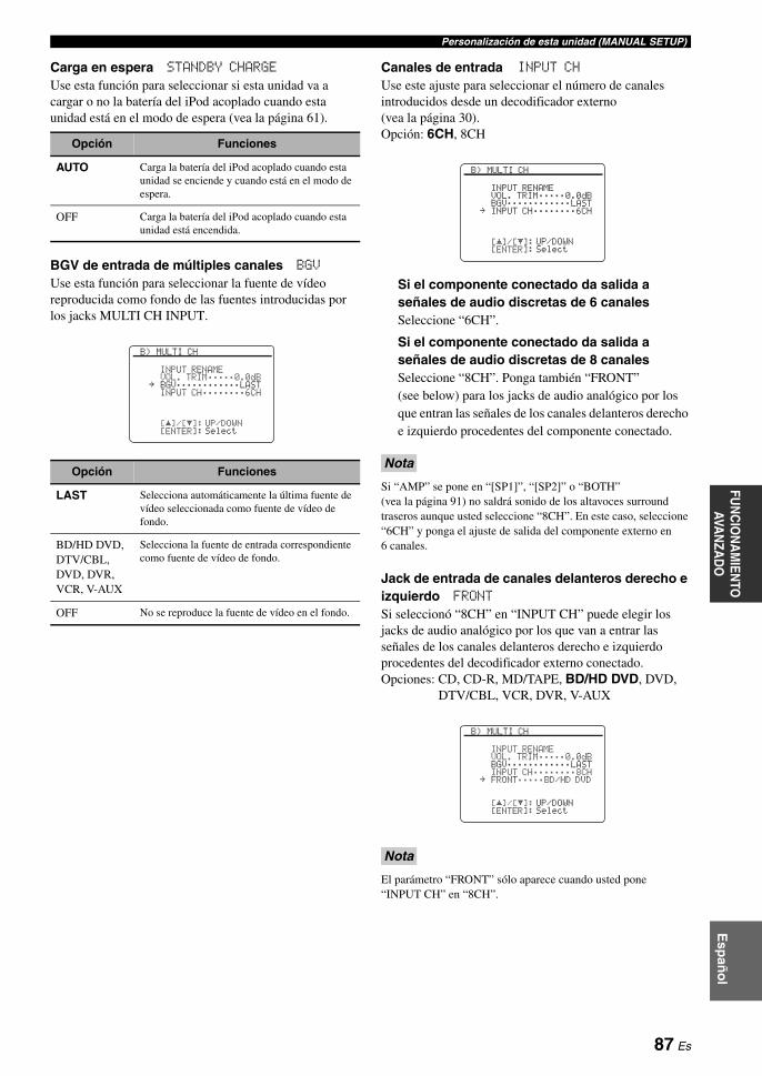
Personalización de esta unidad (MANUAL SETUP)FU
NC
ION
AM
IENTO
AVA
NZA
DO
Esp
año
l
Carga en espera STANDBY CHARGE
Use esta función para seleccionar si esta unidad va a cargar o no la batería del iPod acoplado cuando esta unidad está en el modo de espera (vea la página 61).
BGV de entrada de múltiples canales BGV
Use esta función para seleccionar la fuente de vídeo reproducida como fondo de las fuentes introducidas por los jacks MULTI CH INPUT.
Canales de entrada INPUT CH
Use este ajuste para seleccionar el número de canales introducidos desde un decodificador externo (vea la página 30).Opción: 6CH, 8CH
Si el componente conectado da salida a señales de audio discretas de 6 canales Seleccione “6CH”.
Si el componente conectado da salida a señales de audio discretas de 8 canales Seleccione “8CH”. Ponga también “FRONT” (see below) para los jacks de audio analógico por los que entran las señales de los canales delanteros derecho e izquierdo procedentes del componente conectado.
Si “AMP” se pone en “[SP1]”, “[SP2]” o “BOTH” (vea la página 91) no saldrá sonido de los altavoces surround traseros aunque usted seleccione “8CH”. En este caso, seleccione “6CH” y ponga el ajuste de salida del componente externo en 6 canales.
Jack de entrada de canales delanteros derecho e izquierdo FRONT
Si seleccionó “8CH” en “INPUT CH” puede elegir los jacks de audio analógico por los que van a entrar las señales de los canales delanteros derecho e izquierdo procedentes del decodificador externo conectado.Opciones: CD, CD-R, MD/TAPE, BD/HD DVD, DVD,
DTV/CBL, VCR, DVR, V-AUX
El parámetro “FRONT” sólo aparece cuando usted pone “INPUT CH” en “8CH”.
Opción Funciones
AUTO Carga la batería del iPod acoplado cuando esta unidad se enciende y cuando está en el modo de espera.
OFF Carga la batería del iPod acoplado cuando esta unidad está encendida.
Opción Funciones
LAST Selecciona automáticamente la última fuente de vídeo seleccionada como fuente de vídeo de fondo.
BD/HD DVD, DTV/CBL, DVD, DVR, VCR, V-AUX
Selecciona la fuente de entrada correspondiente como fuente de vídeo de fondo.
OFF No se reproduce la fuente de vídeo en el fondo.
[]/[]:[ENTER]:
[ p
B) MULTI CH
INPUT RENAMEVOL. TRIM;;;;;0.0dBBGV;;;;;;;;;;;;LASTINPUT CH;;;;;;;;6CH
UP/DOWNSelect
.
Nota
Nota
[]/[]:[ENTER]:
[ p
B) MULTI CH
INPUT RENAMEVOL. TRIM;;;;;0.0dBBGV;;;;;;;;;;;;LASTINPUT CH;;;;;;;;6CH
UP/DOWNSelect
.
[]/[]:[ENTER]:
[ p
B) MULTI CH
INPUT RENAMEVOL. TRIM;;;;;0.0dBBGV;;;;;;;;;;;;LASTINPUT CH;;;;;;;;8CHFRONT;;;;;BD/HD DVD
UP/DOWNSelect
.
87 Es
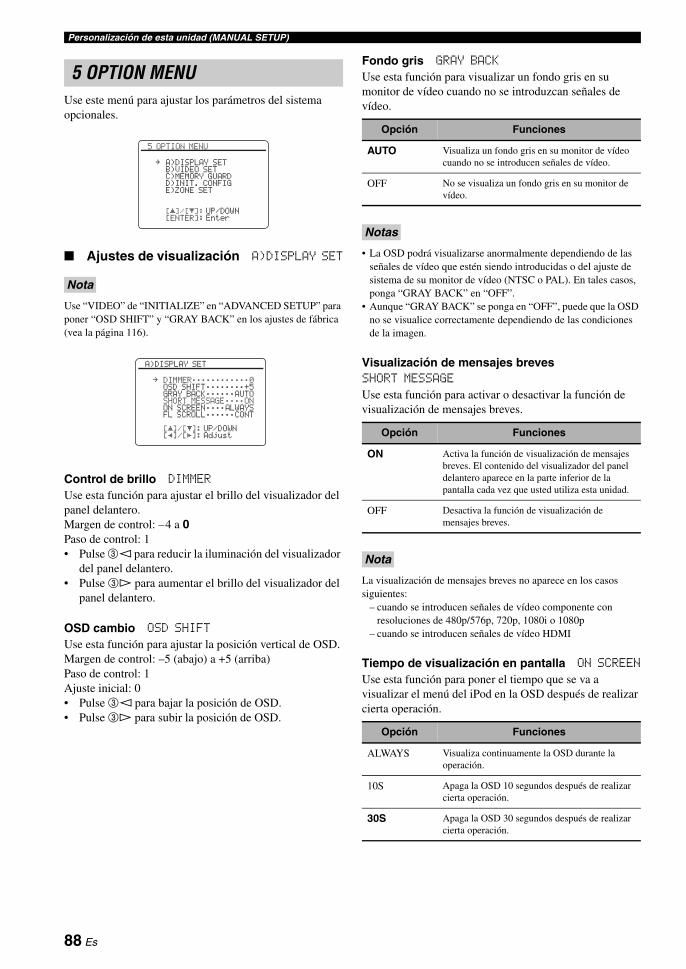
Personalización de esta unidad (MANUAL SETUP)
Use este menú para ajustar los parámetros del sistema opcionales.
Ajustes de visualización A)DISPLAY SET
Use “VIDEO” de “INITIALIZE” en “ADVANCED SETUP” para poner “OSD SHIFT” y “GRAY BACK” en los ajustes de fábrica (vea la página 116).
Control de brillo DIMMER
Use esta función para ajustar el brillo del visualizador del panel delantero.Margen de control: –4 a 0Paso de control: 1• Pulse 3l para reducir la iluminación del visualizador
del panel delantero.• Pulse 3h para aumentar el brillo del visualizador del
panel delantero.
OSD cambio OSD SHIFT
Use esta función para ajustar la posición vertical de OSD.Margen de control: –5 (abajo) a +5 (arriba)Paso de control: 1Ajuste inicial: 0• Pulse 3l para bajar la posición de OSD.• Pulse 3h para subir la posición de OSD.
Fondo gris GRAY BACK
Use esta función para visualizar un fondo gris en su monitor de vídeo cuando no se introduzcan señales de vídeo.
• La OSD podrá visualizarse anormalmente dependiendo de las señales de vídeo que estén siendo introducidas o del ajuste de sistema de su monitor de vídeo (NTSC o PAL). En tales casos, ponga “GRAY BACK” en “OFF”.
• Aunque “GRAY BACK” se ponga en “OFF”, puede que la OSD no se visualice correctamente dependiendo de las condiciones de la imagen.
Visualización de mensajes brevesSHORT MESSAGE
Use esta función para activar o desactivar la función de visualización de mensajes breves.
La visualización de mensajes breves no aparece en los casos siguientes:
– cuando se introducen señales de vídeo componente con resoluciones de 480p/576p, 720p, 1080i o 1080p
– cuando se introducen señales de vídeo HDMI
Tiempo de visualización en pantalla ON SCREEN
Use esta función para poner el tiempo que se va a visualizar el menú del iPod en la OSD después de realizar cierta operación.
5 OPTION MENU
Nota
[]/[]:[ENTER]:
[ p
5 OPTION MENU
A)DISPLAY SETB)VIDEO SETC)MEMORY GUARDD)INIT. CONFIGE)ZONE SET
UP/DOWNEnter
.
[]/[]:[p]/[[]:
[ p
A)DISPLAY SET
DIMMER;;;;;;;;;;;;0OSD SHIFT;;;;;;;;+5GRAY BACK;;;;;;AUTOSHORT MESSAGE;;;;ONON SCREEN;;;;ALWAYSFL SCROLL;;;;;;CONT
UP/DOWNAdjust
.
Opción Funciones
AUTO Visualiza un fondo gris en su monitor de vídeo cuando no se introducen señales de vídeo.
OFF No se visualiza un fondo gris en su monitor de vídeo.
Notas
Opción Funciones
ON Activa la función de visualización de mensajes breves. El contenido del visualizador del panel delantero aparece en la parte inferior de la pantalla cada vez que usted utiliza esta unidad.
OFF Desactiva la función de visualización de mensajes breves.
Nota
Opción Funciones
ALWAYS Visualiza continuamente la OSD durante la operación.
10S Apaga la OSD 10 segundos después de realizar cierta operación.
30S Apaga la OSD 30 segundos después de realizar cierta operación.
88 Es

Personalización de esta unidad (MANUAL SETUP)FU
NC
ION
AM
IENTO
AVA
NZA
DO
Esp
año
l
Desplazamiento de la visualización del panel delantero FL SCROLL
Use esta función para poner el modo de visualización del menú iPod (por ejemplo, título de canción o nombre de canal) en el visualizador del panel delantero.
Ajustes de vídeo B)VIDEO SET
Conversión de vídeo VIDEO CONV.
Use esta función para establecer si va a convertir las señales de vídeo introducidas por los jacks VIDEO, S VIDEO y COMPONENT VIDEO.
• Esta unidad no convierte señales de vídeo de 480 líneas en señales de vídeo de 576 líneas de forma intercambiable.
• Las señales de vídeo componente analógico con resolución de 480i (NTSC)/576i (PAL) se convierten en señales de S-vídeo o vídeo compuesto y salen por los jacks S VIDEO MONITOR OUT y VIDEO MONITOR OUT.
• Las señales de vídeo componente analógico con 1080p de resolución sólo salen por los jacks COMPONENT VIDEO MONITOR OUT.
• Las señales de vídeo convertidas sólo salen a los jacks MONITOR OUT. Cuando grabe una fuente de vídeo tendrá que hacer el mismo tipo de conexiones de vídeo entre cada componente.
• Cuando convierta señales de vídeo compuesto o de S-vídeo procedentes de una videograbadora en señales de vídeo componente, la calidad de la imagen podrá empeorar dependiendo de su videograbadora.
• Ponga “VIDEO CONV.” en “ON” para visualizar los parámetros de campo acústico y los mensajes breves.
• Las señales no convencionales introducidas en los jacks de vídeo compuesto o S-vídeo no se podrán convertir o no podrán salir normalmente. En tales casos, ponga “VIDEO CONV.” en “OFF”.
Conversión ascendente entrelazada/progresiva de componenteCOMPONENT I/P
Use esta función para activar o desactivar la conversión entrelazada/progresiva analógica de las señales de vídeo analógico introducidas en los jacks de vídeo compuesto, S-vídeo y vídeo componente para que las señales de vídeo analógico desentrelazadas de 480i (NTSC)/576i (PAL) a 480p/576p salgan por los jacks COMPONENT MONITOR OUT.
• El parámetro “COMPONENT I/P” sólo aparece cuando usted pone “VIDEO CONV.” en “ON”.
• Si su monitor de vídeo no soporta las señales de vídeo analógico con una resolución 480p/576p, los elementos SET MENU tal vez no se visualicen en su monitor de vídeo cuando “COMPONENT I/P” se ponga en “ON”. En tal caso, ponga el parámetro “COMPONENT I/P” en “OFF”.
Escalado HDMI HDMI SCALING
Use esta función para activar o desactivar el escalado ascendente HDMI de las señales de vídeo analógico introducidas por los jacks VIDEO, S VIDEO y COMPONENT VIDEO, para que las señales de escalado ascendente salgan por el jack HDMI OUT.Esta unidad escala ascendentemente las señales de vídeo de la forma siguiente:• 480i (NTSC)/576i (PAL) → 480p/576p, 1080i, 720p o
1080p• 480p/576p → 1080i, 720p o 1080p
Esta unidad no escala ascendentemente las señales de vídeo componente analógico con 720p o 1080i de resolución.
Opción Funciones
CONT Modo continuo. Seleccione esto para visualizar el estado de operación en el visualizador del panel delantero de forma continua.
ONCE Modo de un desplazamiento.Seleccione esto para visualizar el estado de operación en el visualizador del panel delantero con los primeros 14 caracteres alfanuméricos después de desplazar todos los caracteres una vez.
Opción Funciones
ON Convierte señales de vídeo compuesto, S-vídeo y vídeo componente de forma intercambiable, y convierte en sentido ascendente señales de vídeo compuesto, S-vídeo y vídeo componente en señales de vídeo HDMI.
OFF No convierte ninguna señal.
Notas
[]/[]:[p]/[[]:
[ p
B)VIDEO SET
VIDEO CONV.;;;;;;ONCOMPONENT I/P;;;OFFHDMI SCALING;;;480pHDMI ASPECT;;;THRGH
UP/DOWNSelect
.
Opción Funciones
ON Activa la conversión ascendente entrelazada/progresiva analógica de las señales de vídeo analógico.
OFF Desactiva la conversión ascendente entrelazada/progresiva analógica de las señales de vídeo analógico.
Notas
Opción Funciones
THROUGH No escala ascendentemente ninguna señal de vídeo analógico.
480p (o 576p), 1080i, 720p, 1080p
Escala ascendentemente las señales de vídeo analógico a 480p o 576p, 1080i, 720p o 1080p de resolución.
Nota
89 Es

Personalización de esta unidad (MANUAL SETUP)
• El parámetro “HDMI SCALING” sólo aparece cuando usted pone “VIDEO CONV.” en “ON”.
• Si conecta su monitor de vídeo mediante la conexión HDMI, esta unidad detectará automáticamente la resolución de la señal de vídeo disponible del monitor de vídeo, y aparecerá un asterisco (*) a la izquierda de la resolución (o resoluciones) de la señal de vídeo disponible.
• Si esta unidad no puede detectar la resolución (o resoluciones) de vídeo disponible del monitor de vídeo conectado, ponga “MONITOR CHECK” (vea la página 116) en “SKIP” y luego en “HDMI SCALING” otra vez.
• Esta unidad no convierte entre señales de vídeo de 480 líneas y señales de vídeo de 576 líneas.
Relación de aspecto HDMI HDMI ASPECT
Use esta función para seleccionar el ajuste de la relación de aspecto para las señales de vídeo analógico que salen por el jack HDMI OUT.
• Cuando “HDMI SCALING” se pone en “THROUGH”, usted no podrá hacer ningún ajuste en “HDMI ASPECT”.
• Si la relación de aspecto de la fuente de vídeo de entrada no es 4:3, esta unidad ignora automáticamente el ajuste de “HDMI ASPECT”.
• Cuando “HDMI ASPECT” se ponga en “SMART”, las imágenes del borde del monitor de vídeo se alargarán algo.
• Cuando las señales de vídeo se introduzcan en los jacks HDMI IN o se introduzcan con una resolución de 720p, 1080i o 1080p, el ajuste de “HDMI ASPECT” no afectará a las señales de vídeo que salgan por el jack HDMI OUT.
Protección de memoria C)MEMORY GUARD
Utilice esta función para impedir cambios por error en el parámetro de programa de campo acústico y en otros ajustes del sistema.
• Puede cambiar los parámetros siguientes, aunque “MEMORY GUARD” se ponga en “ON”:
– Parámetros “AUDIO SET” (vea la página 84)– “DECODER MODE” (vea la página 86)– “MEMORY GUARD”
• Cuando “MEMORY GUARD” se pone en “ON”, “ ” aparece en la parte superior derecha de la pantalla “SET MENU”.
Notas
Opción Funciones
THROUGH No hace ningún ajuste en la relación de aspecto para las fuentes de señales de vídeo HDMI.
16:9 Visualiza imágenes cuya relación de aspecto es 4:3 en su monitor de vídeo cuya relación de aspecto de 16:9. En los lados derecho e izquierdo aparecen bandas negras.
SMART Ajuste las imágenes con una relación de aspecto de 4:3 en su monitor de vídeo con una relación de aspecto de 16:9.
Notas
Opción Funciones
OFF Desactiva la función “MEMORY GUARD”.
ON Protege:– parámetros de programas de campos
acústicos– Elementos “AUTO SETUP”– “SYSTEM MEMORY” (“SAVE”)– todos los niveles de altavoces– los elementos “MANUAL SETUP”
Notas
[p]/[[]:[ENTER]:
C)MEMORY GUARD
>OFF ON
SelectReturn
G
90 Es

Personalización de esta unidad (MANUAL SETUP)FU
NC
ION
AM
IENTO
AVA
NZA
DO
Esp
año
l
Configuración inicial D)INIT. CONFIG
Use esta función para seleccionar los ajustes de selección de jack de entrada de audio, los decodificadores activos y el sonido surround ampliado cuando encienda esta unidad.
Selección de audio AUDIO SELECT
Use esta función para designar el ajuste de selección de jack de entrada de audio predeterminado (vea la página 43) para las fuentes de entrada conectadas a los jacks DIGITAL INPUT cuando usted conecte la alimentación de esta unidad.
Modo de decodificador DECODER MODE
Use esta función para designar el modo de decodificador predeterminado (vea la página 86) para las fuentes de entrada conectadas a los jacks DIGITAL INPUT cuando conecte la alimentación de esta unidad.
Surround expandido EXTD SUR.
Use esta función para designar el modo de decodificador expandido (vea la página 84) para las fuentes de entrada conectadas a los jacks DIGITAL INPUT cuando conecte la alimentación de esta unidad.
Ajuste de zona E)ZONE SET
Use esta función para ajustar los elementos relacionados en Zone 2 o Zone 3.
Ajuste de zonaSeleccione la zona en la que va a ajustar “AMP”, “VOLUME”, “MAX VOL.” y “INIT. VOL.”.
Zone 2/Zone 3 amplificador AMP
Use esta función para seleccionar cómo se van a amplificar los altavoces Zone 2 o Zone 3. Este parámetro afecta también a los ajustes de los altavoces y a la salida de sonido de los programas de campos acústicos en la zona principal.Opción: EXT, [SP1], [SP2], BOTH
Cuando los altavoces en Zone 2 o Zone 3 estén conectados al amplificador externo y el amplificador externo esté conectado a los jacks ZONE OUT (ZONE 2 o ZONE 3) de esta unidad:Seleccione “EXT”. Consulte “Utilización de amplificadores externos” en la página 108 para conocer detalles.
Cuando “BI-AMP” se pone en “ON” en “ADVANCED SETUP” (vea la página 116), sólo puede poner “AMP” en “EXT” en “ZONE 2” o “ZONE 3”.
Cuando los altavoces en Zone 2 o Zone 3 estén conectados directamente a los terminales SP1 de esta unidad:Seleccione “[SP1]”. Consulte “Uso de los amplificadores internos de esta unidad” en la página 109 para conocer detalles.
Cuando ponga “AMP” en “[SP1]” en “ZONE 2” o “ZONE 3” y la zona correspondiente se encienda no saldrá sonido por los altavoces surround traseros.
Opción Funciones
AUTO Detecta automáticamente el tipo de las señales de entrada de audio y selecciona el ajuste apropiado de selección de jack de entrada de audio.
LAST Selecciona automáticamente el último ajuste de selección de jack de entrada de audio para la fuente de entrada conectada.
Opción Funciones
AUTO Detecta automáticamente los tipos de las señales de entrada y selecciona el el ajuste apropiado del modo de decodificador.
LAST Selecciona automáticamente el último ajuste del modo de decodificador usado para la fuente de entrada conectada.
Opción Funciones
AUTO Detecta automáticamente las señales de entrada de audio digital y activa el decodificador apropiado.
LAST Selecciona automáticamente el último decodificador para “EXTD SUR.” en “SOUND MENU”.
[p]/[[]:[ENTER]:
D)INIT. CONFIG
AUDIO SELECT;;AUTODECODER MODE;;AUTOEXTD SUR.;;;;;AUTO
SelectReturn
.
Opción Funciones
ZONE2 Ajusta los parámetros “ZONE SET” para Zone 2.
ZONE3 Ajusta los parámetros “ZONE SET” para Zone 3.
Nota
Nota
[]/[]:[p]/[[]:
[ p
E)ZONE SET
>ZONE2 ZONE3
AMP;;;;;;;;;;;;EXTVOLUME;;;;;;;;;VARMAX VOL.;;;-30.0dBINIT. VOL.;+16.5dB
UP/DOWNSelect
.
91 Es

Personalización de esta unidad (MANUAL SETUP)
Cuando los altavoces en Zone 2 o Zone 3 estén conectados directamente a los terminales SP2 de esta unidad:Seleccione “[SP2]”. Consulte “Uso de los amplificadores internos de esta unidad” en la página 109 para conocer detalles.
Cuando ponga “AMP” en “[SP2]” en “ZONE 2” o “ZONE 3” y la zona correspondiente se encienda no saldrá sonido por los altavoces surround.
Si los altavoces en Zone 2 o Zone 3 están conectados a ambos terminales de altavoces SP1 y SP2 (por ejemplo, los altavoces están conectados mediante la conexión de biamplificador o hay cuatro altavoces en una habitación) o si usted quiere reproducir simultáneamente la misma fuente en Zone 2 y Zone 3:Seleccione “BOTH”. Consulte “Uso de los amplificadores internos de esta unidad” en la página 109 para conocer detalles.
• Cuando ponga “AMP” en “BOTH” en “ZONE 2” o “ZONE 3”, sólo podrá poner “AMP” en “EXT” en el ajuste de otra zona.
• Cuando ponga “AMP” en “BOTH” en “ZONE 2” o “ZONE 3” y la zona correspondiente se encienda no saldrá sonido por ambos altavoces: altavoces surround y altavoces surround traseros.
Volumen Zone 2/Zone 3 VOLUME
Use esta función para seleccionar si esta unidad controla el nivel de sonido de las señales de audio que salen por los jacks ZONE OUT (ZONE 2 o ZONE 3) cuando pone “AMP” en “EXT” (vea la página 91).Opción: VAR, FIX
Cuando quiera controlar el nivel de sonido de la zona seleccionada en esta unidad:Seleccione “VAR”. Puede ajustar simultáneamente el nivel de sonido de ZONE OUT (ZONE 2 o ZONE 3)
con BVOLUME +/– en el mando a distancia.
Cuando quiera controlar el nivel de sonido de la zona seleccionada en el amplificador externo:Seleccione “FIX”. Esta unidad fija el nivel de sonido de ZONE OUT (ZONE 2 o ZONE 3) al nivel de línea estándar.
Volumen máximo Zone 2/Zone 3 MAX VOL.
Use esta función para ajustar el nivel de volumen máximo en la Zone 2 o Zone 3.Margen de control: –30,0 dB a +15,0 dB, +16,5 dBPaso de control: 5,0 dB
El ajuste “MAX VOL.” tiene prioridad sobre el ajuste “INIT. VOL.”. Por ejemplo, si “INIT. VOL.” se pone en –20,0 dB y luego “MAX VOL.” se pone en –30,0 dB, el nivel del sonido se pondrá automáticamente en –30,0 dB cuando encienda esta unidad la próxima vez.
volumen inicial Zone 2/Zone 3 INIT. VOL.
Use esta función para ajustar el nivel de sonido de Zone 2 o Zone 3 cuando se conecta la alimentación de Zone 2 o Zone 3.Opciones: OFF, MUTE, –80,0 dB a +16,5 dBPaso de control: 0,5 dB
El ajuste “MAX VOL.” tiene prioridad sobre el ajuste “INIT. VOL.”.
Nota
Notas
Nota
Nota
92 Es
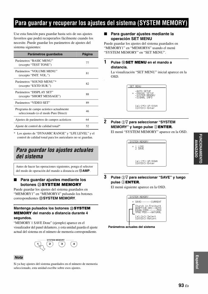
Esp
año
lFU
NC
ION
AM
IENTO
AVA
NZA
DO
Use esta función para guardar hasta seis de sus ajustes favoritos que podrá recuperarlos fácilmente cuando los necesite. Puede guardar los parámetros de ajustes del sistema siguientes:
* Los ajustes de “DYNAMIC RANGE” y “LFE LEVEL” y el control de calidad tonal para los auriculares no se guardan.
Para guardar ajustes mediante los botones MSYSTEM MEMORY
Puede guardar los ajustes del sistema guardados en “MEMORY1” en “MEMORY4” pulsando los botones correspondientes MSYSTEM MEMORY.
Mantenga pulsados los botones MSYSTEM MEMORY del mando a distancia durante 4 segundos.“MEMORY 1 SAVE Done” (ejemplo) aparece en el visualizador del panel delantero, y esta unidad guarda el ajuste actual del sistema en el número de memoria correspondiente.
Si ya hay ajustes del sistema guardados en el número de memoria seleccionado, esta unidad escribe sobre esos ajustes.
Para guardar ajustes mediante la operación SET MENU
Puede guardar los ajustes del sistema guardados en “MEMORY1” en “MEMORY6” usando el menú “SYSTEM MEMORY” en “SET MENU”.
1 Pulse FSET MENU en el mando a distancia.La visualización “SET MENU” inicial aparece en la OSD.
o
2 Pulse 3n para seleccionar “SYSTEM MEMORY” y luego pulse 3ENTER.El menú “SYSTEM MEMORY” aparece en la OSD.
3 Pulse 3n para seleccionar “SAVE” y luego pulse 3ENTER.El menú siguiente aparece en la OSD.
Para guardar y recuperar los ajustes del sistema (SYSTEM MEMORY)
Parámetros guardados Página
Parámetros “BASIC MENU”(excepto “TEST TONE”)
77
Parámetros “VOLUME MENU”(excepto “INIT. VOL.”)
81
Parámetros “SOUND MENU”*(excepto “EXTD SUR.”)
82
Parámetros “DISPLAY SET”(excepto “SHORT MESSAGE”)
88
Parámetros “VIDEO SET” 89
Programa de campo acústico actualmente seleccionado (o el modo Pure Direct)
46
Ajustes de parámetros de campos acústicos 64
Ajuste de control de calidad tonal* 52
Para guardar los ajustes actuales del sistema
Antes de hacer las operaciones siguientes, ponga el selector del modo de operación del mando a distancia en CAMP.
Nota
4321
SYSTEM MEMORY
[]/[]:[ENTER]:
[ p
SET MENU
;AUTO SETUP;MANUAL SETUP;SYSTEM MEMORY;SIGNAL INFO
UP/DOWNEnter
.
[]/[]:[ENTER]:
[ pSYSTEM MEMORY
1 LOAD2 SAVE
UP/DOWNEnter
.
[p]/[[]:[ENTER]:
SYSTEM MEMORY
SAVE;;;;;;;CURRENT
Church in FreiburgADAPTIVE DRC;;AUTOEQUALIZER;;;;;;PEQYPAO PEQ;;;NATURAL
SelectReturn
.
Parámetros actuales del sistema
93 Es

Para guardar y recuperar los ajustes del sistema (SYSTEM MEMORY)
4 Pulse repetidamente 3l / h para selecionar el número de memoria deseado (“MEMORY1” a “MEMORY6”).
y• Si los ajustes del sistema ya están guardados en el número
de memoria seleccionado, los ajustes de los parámetros del sistema guardados aparecen en la pantalla de menú. “EMPTY” aparece en la pantalla de menú si no hay ajustes del sistema guardados en el número de memoria seleccionado.
• Si ya hay ajustes del sistema guardados en el número de memoria seleccionado, esta unidad escribe sobre esos ajustes.
• Si guarda ajustes del sistema en “MEMORY1” a “MEMORY4” podrá cargar los ajustes guardados pulsando los botones correspondientes MSYSTEM MEMORY (vea la página 94).
5 Pulse 3ENTER para guardar los ajustes actuales del sistema en el número de memoria seleccionado.
6 Pulse de nuevo FSET MENU para salir de “SET MENU”.
Carga mediante los botones MSYSTEM MEMORY
Puede recuperar los ajustes del sistema guardados en “MEMORY1” en “MEMORY4” pulsando los botones correspondientes MSYSTEM MEMORY.
1 Pulse uno de los botones MSYSTEM MEMORY del mando a distancia para seleccionar el número de memoria deseado.“MEMORY 1 LOAD” (ejemplo) aparece en el visualizador del panel delantero.
y“EMPTY” aparece en la pantalla de menú si no hay ajustes del sistema guardados en el número de memoria seleccionado.
2 Pulse una vez más el botón MSYSTEM MEMORY seleccionado para confirmar la elección.Esta unidad carga los ajustes guardados en el número de memoria seleccionado.
Para cargar ajustes mediante la operación SET MENU
1 Pulse FSET MENU en el mando a distancia.La visualización “SET MENU” inicial aparece en la OSD.
2 Pulse 3n para seleccionar “SYSTEM MEMORY” y luego pulse 3ENTER.El menú “SYSTEM MEMORY” aparece en la OSD.
3 Pulse 3ENTER para seleccionar “LOAD”.El menú siguiente aparece en la OSD.
4 Pulse repetidamente 3l / h para seleccionar el número de memoria deseado donde están guardados los ajustes del sistema, y luego pulse 3ENTER.Esta unidad carga los ajustes seleccionados del sistema.
5 Pulse FSET MENU para salir de “SET MENU”.
Carga de ajustes del sistema guardados
• Antes de hacer las operaciones siguientes, ponga el selector del modo de operación del mando a distancia en CAMP.
• Esta unidad escribe los ajustes guardados sobre los ajustes actuales de esta unidad. Si no quiere borrar los ajustes actuales, guárdelos de antemano en cualquier número SYSTEM MEMORY.
[p]/[[]:[ENTER]:
SYSTEM MEMORY
SAVE;;;;;;;MEMORY1
DramaADAPTIVE DRC;;AUTOEQUALIZER;;;;;;GEQYPAO PEQ;;;;;;NONE
SelectReturn
.
Parámetros del sistema guardados en el número de memoria seleccionado
4321
SYSTEM MEMORY
[p]/[[]:[ENTER]:
SYSTEM MEMORY
LOAD;;;;;;;CURRENT
Church in FreiburgADAPTIVE DRC;;AUTOEQUALIZER;;;;;;PEQYPAO PEQ;;;NATURAL
SelectReturn
.
[p]/[[]:[ENTER]:
SYSTEM MEMORY
LOAD;;;;;;;MEMORY6
StraightADAPTIVE DRC;;AUTOEQUALIZER;;;;;;PEQYPAO PEQ;;;;;;FLAT
SelectLoad
.
94 Es

Para guardar y recuperar los ajustes del sistema (SYSTEM MEMORY)FU
NC
ION
AM
IENTO
AVA
NZA
DO
Esp
año
l
Ejemplo 1: Comparación de los resultados del ajuste automático y del ajuste manual
Esta unidad está equipada con tres tipos de ajustes de ecualizador paramétrico (vea la página 40), y usted también puede hacer una configuración personalizada de los ajustes de sonido de esta unidad usando los parámetros “MANUAL SETUP” (vea la página 72). Para comparar los resultados del ajuste automático o su configuración manual, use los botones MSYSTEM MEMORY.
Para guardar cada ajuste
Siga el procedimiento siguiente cuando todos los parámetros estén ajustados en los valores predeterminados.
1 Mantenga pulsado MSYSTEM MEMORY 1 durante 4 segundos.Esta unidad guarda sus ajustes actuales en “MEMORY1”.
2 Haga el ajuste automático.Ponga “EQ” en “NATURAL”. Vea la página 40 para conocer detalles.
3 Mantenga pulsado MSYSTEM MEMORY 2 durante 4 segundos.Esta unidad guarda los resultados del ajuste automático hecho en el paso 2 en “MEMORY2”.
4 Haga de nuevo el ajuste automático.Ahora, ponga “EQ” en “FRONT”.
5 Mantenga pulsado MSYSTEM MEMORY 3 durante 4 segundos.Esta unidad guarda los resultados del ajuste automático hecho en el paso 4 en “MEMORY3”.
Ejemplo 2: Cambio de los ajustes para habitaciones diferentes
Las características tonales de la habitación de escucha pueden cambiar según la situación de la misma (por ejemplo, si las cortinas están abiertas o cerradas), y los ajustes de esta unidad deberán cambiarse para cada situación de la habitación. Usando los botones MSYSTEM MEMORY puede cambiar fácilmente los ajustes de esta unidad.
Para guardar cada ajuste
1 Cierre las cortinas de la habitación de escucha y luego haga el ajuste automático.Vea la página 37 para conocer detalles del ajuste automático.
2 Mantenga pulsado MSYSTEM MEMORY 1 durante 4 segundos.Esta unidad guarda los ajustes para la situación actual de la habitación (es decir, las cortinas están cerradas) en “MEMORY1”.
3 Abra las cortinas de la habitación de escucha y luego haga el ajuste automático.
4 Mantenga pulsado MSYSTEM MEMORY 2 durante 4 segundos.Esta unidad guarda la situación actual de la habitación (es decir, las cortinas están abiertas) en “MEMORY2”.
Uso de ejemplos
Nota
4
5 76 8
CLASSICAL LIVE/CLUB ENTERTAIN MOVIE
SYSTEM MEMORY
321
SYSTEM MEMORY 1Ajustes actuales de esta unidad
SYSTEM MEMORY 2Los resultados del ajuste automático (EQ: NATURAL)
SYSTEM MEMORY 3Los resultados del ajuste automático (EQ: FRONT)
4
5 76 8
CLASSICAL LIVE/CLUB ENTERTAIN MOVIE
SYSTEM MEMORY
321
SYSTEM MEMORY 1Los ajustes cuando las cortinas de la habitación de escucha están cerradas
SYSTEM MEMORY 2Los ajustes cuando las cortinas de la habitación de escucha están abiertas
95 Es

Para guardar y recuperar los ajustes del sistema (SYSTEM MEMORY)
Ejemplo 3: Para guardar configuraciones de sonido para fuentes específicas
Las configuraciones de sonido deseadas son diferentes para cada fuente de entrada. Por ejemplo, si utiliza el programa de campos acústicos “Village Vanguard” para una fuente de música de un concierto de jazz en directo, los ajustes de parámetros podrán ser diferentes cuando la fuente de entrada sea un disco de vinilo o un SACD. Puede guardar los ajustes de sonido para cada fuente de entrada.
Para guardar cada ajuste
yVea la página 64 para los ajustes de parámetros de programas de campos acústicos.
1 Inicie la reproducción de la actuación de jazz en directo grabada en el SACD.
2 Ponga el programa de campos acústicos en “Village Vanguard” y luego ajuste los parámetros para las fuentes de reproducción actuales.
3 Mantenga pulsado MSYSTEM MEMORY 1 durante 4 segundos.Esta unidad guarda los ajustes actuales del programa de campos acústicos en “MEMORY1”.
4 Cambie la fuente de entrada a “PHONO” y luego inicie la reproducción de la actuación de jazz en directo deseada grabada en el disco de vinilo.
5 Ajuste los parámetros de programas de campos acústicos para la fuente de reproducción actual.
6 Mantenga pulsado MSYSTEM MEMORY 2 durante 4 segundos.Esta unidad guarda los ajustes actuales del programa de campos acústicos en “MEMORY2”.
Ejemplo 4: Cambio de ajustes múltiples de sincronización de audio y vídeo
Si usa dos tipos diferentes de proyectores o monitores de vídeo, y si éstos no son compatibles con la función de sincronización automática de audio y vídeo, usted deberá ajustar “MANUAL DELAY” para cada componente. Usando los botones MSYSTEM MEMORY puede cambiar entre los ajustes “MANUAL DELAY” diferentes.
Para guardar cada ajuste
En el ejemplo siguiente, el monitor de vídeo LCD y un componente de entrada (por ejemplo, VCR) están conectados al jack de entrada S VIDEO y al jack S VIDEO MONITOR OUT, y el proyector de vídeo y el otro componente de entrada (por ejemplo, reproductor DVD) están conectados a uno de los jacks HDMI IN y al jack HDMI OUT.
1 Inicie la reproducción de la fuente de vídeo deseada en el monitor de vídeo LCD conectado y luego ajuste correctamente “MANUAL DELAY” en “SOUND MENU” (vea la página 84).
2 Mantenga pulsado MSYSTEM MEMORY 1 durante 4 segundos.Esta unidad guarda los ajustes de la sincronización de audio y vídeo para el monitor de vídeo LCD en “MEMORY 1”.
3 Cambie la fuente de entrada al componente conectado a uno de los jacks HDMI IN y luego inicie la reproducción.
4 Ajuste correctamente “MANUAL DELAY” en “SOUND MENU”.
5 Mantenga pulsado MSYSTEM MEMORY 2 durante 4 segundos.Esta unidad guarda los ajustes de la sincronización de audio y vídeo para el proyector de vídeo en “MEMORY 2”.
4
5 76 8
CLASSICAL LIVE/CLUB ENTERTAIN MOVIE
SYSTEM MEMORY
321
SYSTEM MEMORY 1El programa “Village Vanguard” configurado para fuentes SACD
SYSTEM MEMORY 2El programa “Village Vanguard” configurado para fuentes de discos de vinilo
Nota
4
5 76 8
CLASSICAL LIVE/CLUB ENTERTAIN MOVIE
SYSTEM MEMORY
321
SYSTEM MEMORY 1Los ajustes para el monitor de vídeo LCD conectado al jack S VIDEO MONITOR OUT
SYSTEM MEMORY 2Los ajustes para el proyector de vídeo conectado al jack HDMI OUT
96 Es

Esp
año
lFU
NC
ION
AM
IENTO
AVA
NZA
DO
Además de controlar esta unidad, el mando a distancia también puede controlar otros componentes audiovisuales hechos por Yamaha y otros fabricantes. Para controlar su TV u otros componentes deberá preparar el código de mando a distancia apropiado para cada fuente de entrada (vea la página 99).
Control de esta unidadPonga el selector del modo de operación en CAMP para controlar esta unidad.
*1 Estos botones controlan siempre esta unidad independientemente de la posición del selector del modo de operación.
*2 Estos botones controlan esta unidad sólo cuando el selector del modo de operación se pone en CAMP.
Control de un TVPonga el selector del modo de operación en CTV para controlar su TV. Para controlar su TV tendrá que poner de antemano el código de mando a distancia apropiado para DTV/CBL o PHONO (vea la página 99). Cuando ponga los códigos de mando a distancia para DTV y PHONO, tendrá prioridad el puesto para DTV.
*1 Estos botones controlan siempre su TV independientemente de la posición del selector del modo de operación.
*2 Estos botones controlan su TV sólo cuando el selector del modo de operación se pone en CTV. Para conocer detalles, vea la columna “TV” en la página 98.
Funciones del mando a distancia
Control de esta unidad, un TV u otros componentes
Notas
–
+ +
––
+
ENTER
DISPLAY
AUDIO
MENUTITLE
TV MUTE TV INPUT MUTE
432
ENT+1009
5
1
AVTV
76 8
RETURN
ONOFF CLEARLEARN RENAMEMACRO
REC
DISC SKIP
VOLUMECHTV VOL
EFFECT
PARAMETER STRAIGHTA/B/C/D/E
SRCH MODE
PURE DIRECTPRESET/CH
SET MENU
BAND
LEVEL
CLASSICAL LIVE/CLUB ENTERTAIN MOVIE
SYSTEM MEMORY
SUR. DECODE
FREQ/TEXT EON MODE – PTY SEEK – START
ENHANCERSTEREO
TV
SOURCE
AMP
SELECT
DTV/CBL VCRDVR V-AUX/DOCK
TUNER CD CD-R MULTI CH IN
POWER POWER POWERSTANDBY
SLEEPAUDIO SEL
DVD BD/HD DVD PHONOMD/TAPE
Ponga en AMP
*1
*1
*1
*2
Notas
Mando a distancia TV digital/TV por cable
TV POWER Activa o desactiva la alimentación.
TV VOL +/–Aumenta o disminuye el nivel del sonido.
TV MUTE Silencia la salida de audio.
TV INPUT Cambia la fuente de entrada.
–
+ +
––
+
ENTER
DISPLAY
AUDIO
MENUTITLE
TV MUTE TV INPUT MUTE
432
ENT+1009
5
1
AVTV
76 8
RETURN
ONOFF CLEARLEARN RENAMEMACRO
REC
DISC SKIP
VOLUMECHTV VOL
EFFECT
PARAMETER STRAIGHTA/B/C/D/E
SRCH MODE
PURE DIRECTPRESET/CH
SET MENU
BAND
LEVEL
CLASSICAL LIVE/CLUB ENTERTAIN MOVIE
SYSTEM MEMORY
SUR. DECODE
FREQ/TEXT EON MODE – PTY SEEK – START
ENHANCERSTEREO
TV
SOURCE
AMP
SELECT
DTV/CBL VCRDVR V-AUX/DOCK
TUNER CD CD-R MULTI CH IN
POWER POWER POWERSTANDBY
SLEEPAUDIO SEL
DVD BD/HD DVD PHONOMD/TAPE
Ponga en TV
*1
*1
*2
*2
*2
97 Es

Funciones del mando a distancia
Control de otros componentesPonga el selector del modo de operación en CSOURCE para controlar otros componentes seleccionados con los botones selectores de entrada (1) o . Deberá poner de antemano el código de mando a distancia apropiado para cada fuente de entrada (vea la página 99). La tabla siguiente muestra la función de cada botón de control usado para controlar otros componentes asignados a cada botón selector de entrada (1) o . Tenga en cuenta que algunos botones no controlarán correctamente el componente seleccionado.
yEl mando a distancia tiene 14 modos (áreas de entrada) para controlar componentes, por lo que puede controlar hasta 14 componentes diferentes.
*1 Este botón sólo funciona cuando el mando a distancia original suministrado con el componente tiene un botón de alimentación.*2 Estos botones controlan su videograbadora (grabador DVD, etc.) sólo cuando usted pone el código de mando a distancia apropiado
para DVR (vea la página 99).*3 Estos botones controlan su TV sólo cuando el selector del modo de operación se pone en TV. Para conocer detalles, vea la columna “TV”.
–
+ +
––
+
ENTER AUDIO
MENUTITLE
TV MUTE TV INPUT MUTE
AVTV
ENTER
DISPLAY
AUDIO
MENUTITLE
TV MUTE TV INPUT MUTE
432
ENT+1009
5
1
76 8
RETURN
VOLUMECHTV VOL
SRCH MODE
PURE DIRECTPRESET/CH
SET MENU
BAND
LEVEL
TV
SOURCE
AMP
SELECT
DTV/CBL VCRDVR V-AUX/DOCK
TUNER CD CD-R MULTI CH IN
POWER POWER POWERSTANDBY
SLEEPAUDIO SEL
DVD BD/HD DVD PHONOMD/TAPE
ONOFF CLEARLEARN RENAMEMACRO
REC
DISC SKIP
EFFECT
PARAMETER STRAIGHTA/B/C/D/E
SRCH MODE
PURE DIRECTPRESET/CH
SET MENU
BAND
LEVEL
CLASSICAL LIVE/CLUB ENTERTAIN MOVIE
SYSTEM MEMORY
SUR. DECODE
FREQ/TEXT EON MODE – PTY SEEK – START
ENHANCERSTEREO
[1][3][4][5]
[6]
[7][2]
[8][9]
[10]
[11]
Ponga enSOURCE
Reproductor/Grabador de Blu-ray Disc/HD DVD
Reproductor DVD/Grabadora DVD
VCR
TV por cable/Sintonizador de satélite
TV Reproductor LD
Reproductor CD
Grabadora MD/Grabadora CD
Platina de cinta Sintonizador
[1] AV POWERAlimentación *1 Alimentación *1 Alimentación *1 Alimentación *1
Alimentación de DVR *2 Alimentación *1 Alimentación *1 Alimentación *1 Alimentación *1 Alimentación *1
[2] CH + Canal de TV superior*3
Canal de TV superior*3
Canal superior
Canal superior
Canal superior
Canal de TV superior*3
Canal de TV superior*3
Canal de TV superior*3
Canal de TV superior*3
Canal de TV superior*3
CH –Canal de TV inferior*3
Canal de TV inferior*3 Canal inferior Canal inferior Canal inferior
Canal de TV inferior*3
Canal de TV inferior*3
Canal de TV inferior*3
Canal de TV inferior*3
Canal de TV inferior*3
[3] TITLE Título Título Título Título Título Banda
[4] ENTER Introducción de menú
Introducción de menú
Selección de menú
Selección de menú
PRESET/CH k Menú arriba Menú arriba Menú arriba Menú arribaEmisora presintonizada superior (1 a 8)
PRESET/CH n Menú abajo Menú abajo Menú abajo Menú abajoEmisora presintonizada inferior (1 a 8)
A/B/C/D/E lMenú izquierda
Menú izquierda
Menú izquierda
Menú izquierda
Emisora presintonizada inferior (A a E)
A/B/C/D/E h Menú derecha Menú derecha Menú derecha Menú derecha Dirección A/BEmisora presintonizada superior (A a E)
[5] RETURN Retorno Retorno Retorno Retorno Retorno
[6] 1-9, 0, +10 Botones numéricos
Botones numéricos
Botones numéricos
Botones numéricos
Botones numéricos
Botones numéricos
Botones numéricos
Botones numéricos
[7] ll Búsqueda hacia atrás
Búsqueda hacia atrás
Búsqueda hacia atrás
DVR búsqueda hacia atrás *2
DVR búsqueda hacia atrás *2
Búsqueda hacia atrás
Búsqueda hacia atrás
Búsqueda hacia atrás
Búsqueda hacia atrás
hhBúsqueda hacia adelante
Búsqueda hacia adelante
Búsqueda hacia adelante
DVR búsqueda hacia delante *2
DVR búsqueda hacia delante *2
Búsqueda hacia adelante
Búsqueda hacia adelante
Búsqueda hacia adelante
Búsqueda hacia adelante
bSalto hacia atrás
Salto hacia atrás
Capítulo/Salto hacia atrás
Salto hacia atrás
Salto hacia atrás
Dirección de retroceso
aSalto hacia adelante
Salto hacia adelante
Capítulo/Salto hacia adelante
Salto hacia adelante
Salto hacia adelante
Dirección de avance
REC/ DISC SKIP
Grabación (grabadora)
Salto de disco (reproductor)Grabación (grabadora)
GrabaciónDVR grabación *2
DVR grabación *2 Salto de disco Grabación Grabación
s Parada Parada Parada DVR parada *2 DVR parada *2 Parada Parada Parada Parada
e Pausa Pausa Pausa DVR pausa *2 DVR pausa *2 Pausa Pausa Pausa Pausa
p Reproducción Reproducción ReproducciónDVR reproducción *2
DVR reproducción *2 Reproducción Reproducción Reproducción Reproducción
[8] MENU Menú Menú Menú Menú
[9] AUDIO Audio Audio Audio
[10] DISPLAY Visualizador Visualizador Visualizador Visualizador Visualizador Visualizador Visualizador
[11] ENT Entrar Entrar/recuperar Entrar
Notas
98 Es

Funciones del mando a distanciaFU
NC
ION
AM
IENTO
AVA
NZA
DO
Esp
año
l
Selección de un componente para controlar
Puede seleccionar un componente para ser controlado independientemente de la fuente de entrada seleccionada con los botones selectores de entrada (1).
Pulse repetidamente ASELECT k / n para seleccionar el componente deseado.El nombre del componente que va a ser controlado aparece en el visualizador (A) del mando a distancia.
Control de componentes opcionales (Modo opcional)
“OPTN” es un área de control de componentes opcionales que puede programarse con funciones de mando a distancia independientemente de cualquier fuente de entrada. Este área resulta útil para programar comandos que van a ser utilizados solamente como una parte de una función macro o para componentes que no tienen un código de mando a distancia válido.
Para seleccionar el modo opcional, pulse repetidamente ASELECT n hasta que “OPTN” aparezca en el visualizador del mando a distancia.
No puede poner un código de mando a distancia para el área opcional. Vea la página 101 para programar botones utilizados dentro de esta área de control de componentes.
Estableciendo los códigos de mando a distancia apropiados puede controlar otros componentes. Se pueden preparar códigos para cada área de entrada. Para conocer una lista completa de los códigos de mando a distancia disponibles, consulte “Lista de códigos de mando a distancia” al final de este manual.
La tabla siguiente muestra el componente predeterminado (Librería: categoría de componente) y el código de mando a distancia para cada área de entrada.
Ajustes predeterminados de códigos de mando a distancia
Tal vez no pueda controlar su componente Yamaha aunque se preajuste un código de fabricante Yamaha listado arriba. En este caso, intente poner otros códigos de mando a distancia Yamaha.
Nota
SELECT
SELECT
Puesta de los códigos de mando a distancia
Área de entrada
Librería(categoría de componente)
FabricanteCódigo
predeterminado
TAPE — 2700
TUNER Yamaha 2607
TUNER TUNER Yamaha 2602
CD CD Yamaha 2300
CD-R CD-R Yamaha 2400
MULTI CH IN
DVD Yamaha 2100
MD/TAPE MD Yamaha 2500
DVD DVD Yamaha 2100
BD/HD DVD DVD Yamaha 2100
PHONO TV — —
DTV/CBL TV — —
DVR DVR Yamaha 2807
VCR VCR — —
V-AUX/DOCK
TUNER Yamaha 2606
Nota
99 Es
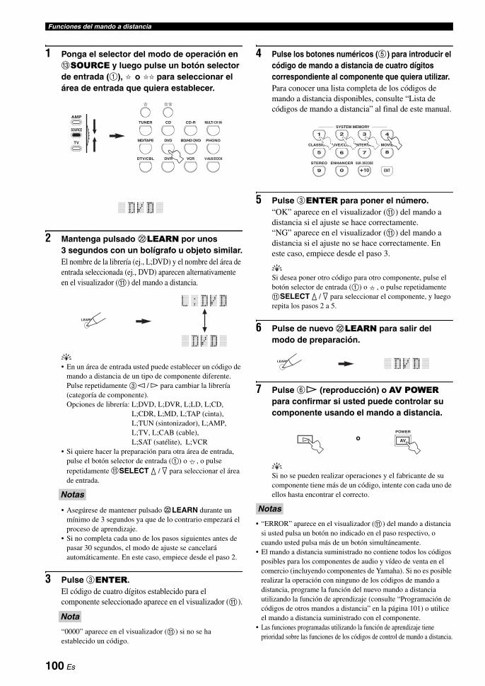
Funciones del mando a distancia
1 Ponga el selector del modo de operación en CSOURCE y luego pulse un botón selector de entrada (1), o para seleccionar el área de entrada que quiera establecer.
2 Mantenga pulsado LLEARN por unos 3 segundos con un bolígrafo u objeto similar.El nombre de la librería (ej., L;DVD) y el nombre del área de entrada seleccionada (ej., DVD) aparecen alternativamente en el visualizador (A) del mando a distancia.
y• En un área de entrada usted puede establecer un código de
mando a distancia de un tipo de componente diferente. Pulse repetidamente 3l / h para cambiar la librería (categoría de componente).Opciones de librería: L;DVD, L;DVR, L;LD, L;CD,
L;CDR, L;MD, L;TAP (cinta), L;TUN (sintonizador), L;AMP, L;TV, L;CAB (cable), L;SAT (satélite), L;VCR
• Si quiere hacer la preparación para otra área de entrada, pulse el botón selector de entrada (1) o , o pulse repetidamente ASELECT k / n para seleccionar el área de entrada.
• Asegúrese de mantener pulsado LLEARN durante un mínimo de 3 segundos ya que de lo contrario empezará el proceso de aprendizaje.
• Si no completa cada uno de los pasos siguientes antes de pasar 30 segundos, el modo de ajuste se cancelará automáticamente. En este caso, empiece desde el paso 2.
3 Pulse 3ENTER.El código de cuatro dígitos establecido para el componente seleccionado aparece en el visualizador (A).
“0000” aparece en el visualizador (A) si no se ha establecido un código.
4 Pulse los botones numéricos (5) para introducir el código de mando a distancia de cuatro dígitos correspondiente al componente que quiera utilizar.Para conocer una lista completa de los códigos de mando a distancia disponibles, consulte “Lista de códigos de mando a distancia” al final de este manual.
5 Pulse 3ENTER para poner el número.“OK” aparece en el visualizador (A) del mando a distancia si el ajuste se hace correctamente.“NG” aparece en el visualizador (A) del mando a distancia si el ajuste no se hace correctamente. En este caso, empiece desde el paso 3.
ySi desea poner otro código para otro componente, pulse el botón selector de entrada (1) o , o pulse repetidamente ASELECT k / n para seleccionar el componente, y luego repita los pasos 2 a 5.
6 Pulse de nuevo LLEARN para salir del modo de preparación.
7 Pulse 6p (reproducción) o AV POWER para confirmar si usted puede controlar su componente usando el mando a distancia.
ySi no se pueden realizar operaciones y el fabricante de su componente tiene más de un código, intente con cada uno de ellos hasta encontrar el correcto.
• “ERROR” aparece en el visualizador (A) del mando a distancia si usted pulsa un botón no indicado en el paso respectivo, o cuando usted pulsa más de un botón simultáneamente.
• El mando a distancia suministrado no contiene todos los códigos posibles para los componentes de audio y vídeo de venta en el comercio (incluyendo componentes de Yamaha). Si no es posible realizar la operación con ninguno de los códigos de mando a distancia, programe la función del nuevo mando a distancia utilizando la función de aprendizaje (consulte “Programación de códigos de otros mandos a distancia” en la página 101) o utilice el mando a distancia suministrado con el componente.
• Las funciones programadas utilizando la función de aprendizaje tiene prioridad sobre las funciones de los códigos de control de mando a distancia.
Notas
Nota
DTV/CBL VCRDVR V-AUX/DOCK
TUNER CD CD-R MULTI CH IN
DVD BD/HD DVD PHONOMD/TAPETV
SOURCE
AMP
LEARN
Notas
432
ENT+1009
5
1
76 8
CLASSICAL LIVE/CLUB ENTERTAIN MOVIE
SYSTEM MEMORY
SUR. DECODEENHANCERSTEREO
LEARN
AV
POWER
o
100 Es

Funciones del mando a distanciaFU
NC
ION
AM
IENTO
AVA
NZA
DO
Esp
año
l
Puede programar códigos de mando a distancia desde otros mandos a distancia. Utilice la función de aprendizaje si quiere programar funciones no incluidas en las operaciones básicas cubiertas por los códigos de mando a distancia, o si no se encuentra disponible un código de mando a distancia apropiado. Puede programar la función de otro mando a distancia en los botones de las áreas resaltadas en la ilustración siguiente. Los botones se pueden programar independientemente para cada área de entrada.
El mando a distancia transmite rayos infrarrojos. Si el otro mando a distancia utiliza también rayos infrarrojos, este mando podrá aprender la mayoría de sus funciones. Sin embargo, tal vez no pueda programar algunas señales especiales o transmisiones demasiado largas. Consulte las instrucciones de funcionamiento del otro mando a distancia.
1 Ponga el selector del modo de operación en CSOURCE y luego pulse un botón selector de entrada (1) o para seleccionar un área de entrada.
Asegúrese de que el selector del modo de operación esté en CSOURCE. Cuando ponga el selector del modo de operación en CAMP y programe códigos de mando a distancia desde otros mandos a distancia, las teclas programadas no podrán controlar la función de amplificador de esta unidad.
2 Ponga este mando a distancia de 5 a 10 cm del otro mando a distancia y sobre una superficie plana para que sus transmisores de infrarrojos queden uno frente al otro.
3 Pulse LLEARN utilizando un bolígrafo u objeto similar.“LEARN” y el nombre del área de entrada seleccionada (ej. “DVD”) aparecen alternativamente en el visualizador (A) del mando a distancia.
• No pulse y mantenga pulsado LLEARN. Si lo mantiene pulsado durante más de 3 segundos, el mando a distancia se pondrá en el modo de ajuste de códigos de mando a distancia.
• Si no completa cada uno de los pasos siguientes antes de pasar 30 segundos, el modo de aprendizaje se cancelará automáticamente. En este caso, empiece desde el paso 3.
4 Pulse el botón para el que quiere programar la función nueva.“LEARN” aparece en el visualizador (A) del mando a distancia.
Programación de códigos de otros mandos a distancia
Nota
Nota
–
+ +
––
+
MENUTITLE
TV MUTE TV INPUT MUTE
AVTV
ENTER
DISPLAY
AUDIO
MENUTITLE
432
ENT+1009
5
1
76 8
RETURN
VOLUMECHTV VOL
SRCH MODE
PURE DIRECTPRESET/CH
SET MENU
BAND
LEVEL
TV
SOURCE
AMP
SELECT
DTV/CBL VCRDVR V-AUX/DOCK
TUNER CD CD-R MULTI CH IN
POWER POWER POWERSTANDBY
SLEEPAUDIO SEL
DVD BD/HD DVD PHONOMD/TAPE
ONOFF CLEARLEARN RENAMEMACRO
REC
DISC SKIP
EFFECT
PARAMETER STRAIGHTA-E/CAT.
SRCH MODE
PURE DIRECTPRESET/CH
SET MENU
BAND
LEVEL
CLASSICAL LIVE/CLUB ENTERTAIN MOVIE
SYSTEM MEMORY
SUR. DECODE
FREQ/TEXT EON MODE – PTY SEEK – START
ENHANCERSTEREO
Ponga en SOURCE
Notas
AV
TV
SELECT
DT
V/C
BL
VC
RD
VR
V-AUX/DOCK
TU
NE
RC
DC
D-R
MULTI CH IN
PO
WE
RP
OW
ER
PO
WE
RSTANDBY
SL
EE
PA
UD
IO S
EL
DV
DB
D/H
D D
VD
PH
ON
OM
D/TA
PE
5 a 10 cm
Otro mando a distancia
LEARN
101 Es
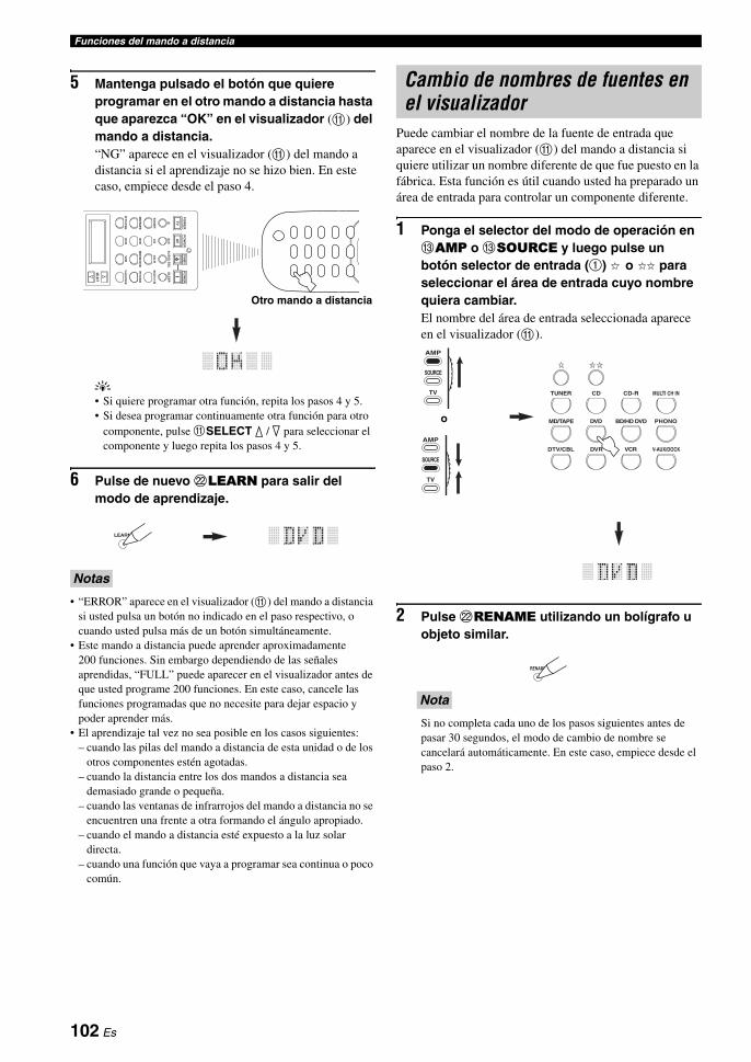
Funciones del mando a distancia
5 Mantenga pulsado el botón que quiere programar en el otro mando a distancia hasta que aparezca “OK” en el visualizador (A) del mando a distancia.“NG” aparece en el visualizador (A) del mando a distancia si el aprendizaje no se hizo bien. En este caso, empiece desde el paso 4.
y• Si quiere programar otra función, repita los pasos 4 y 5.• Si desea programar continuamente otra función para otro
componente, pulse ASELECT k / n para seleccionar el componente y luego repita los pasos 4 y 5.
6 Pulse de nuevo LLEARN para salir del modo de aprendizaje.
• “ERROR” aparece en el visualizador (A) del mando a distancia si usted pulsa un botón no indicado en el paso respectivo, o cuando usted pulsa más de un botón simultáneamente.
• Este mando a distancia puede aprender aproximadamente 200 funciones. Sin embargo dependiendo de las señales aprendidas, “FULL” puede aparecer en el visualizador antes de que usted programe 200 funciones. En este caso, cancele las funciones programadas que no necesite para dejar espacio y poder aprender más.
• El aprendizaje tal vez no sea posible en los casos siguientes:– cuando las pilas del mando a distancia de esta unidad o de los
otros componentes estén agotadas.– cuando la distancia entre los dos mandos a distancia sea
demasiado grande o pequeña.– cuando las ventanas de infrarrojos del mando a distancia no se
encuentren una frente a otra formando el ángulo apropiado.– cuando el mando a distancia esté expuesto a la luz solar
directa.– cuando una función que vaya a programar sea continua o poco
común.
Puede cambiar el nombre de la fuente de entrada que aparece en el visualizador (A) del mando a distancia si quiere utilizar un nombre diferente de que fue puesto en la fábrica. Esta función es útil cuando usted ha preparado un área de entrada para controlar un componente diferente.
1 Ponga el selector del modo de operación en CAMP o CSOURCE y luego pulse un botón selector de entrada (1) o para seleccionar el área de entrada cuyo nombre quiera cambiar.El nombre del área de entrada seleccionada aparece en el visualizador (A).
2 Pulse LRENAME utilizando un bolígrafo u objeto similar.
Si no completa cada uno de los pasos siguientes antes de pasar 30 segundos, el modo de cambio de nombre se cancelará automáticamente. En este caso, empiece desde el paso 2.
NotasA
VT
V
SELECT
DT
V/C
BL
VC
RD
VR
V-AUX/DOCK
TU
NE
RC
DC
D-R
MULTI CH IN
PO
WE
RP
OW
ER
PO
WE
RSTANDBY
SL
EE
PA
UD
IO S
EL
DV
DB
D/H
D D
VD
PH
ON
OM
D/TA
PE
Otro mando a distancia
LEARN
Cambio de nombres de fuentes en el visualizador
Nota
DTV/CBL VCRDVR V-AUX/DOCK
TUNER CD CD-R MULTI CH IN
DVD BD/HD DVD PHONOMD/TAPE
TV
SOURCE
AMP
TV
SOURCE
AMP
o
RENAME
102 Es
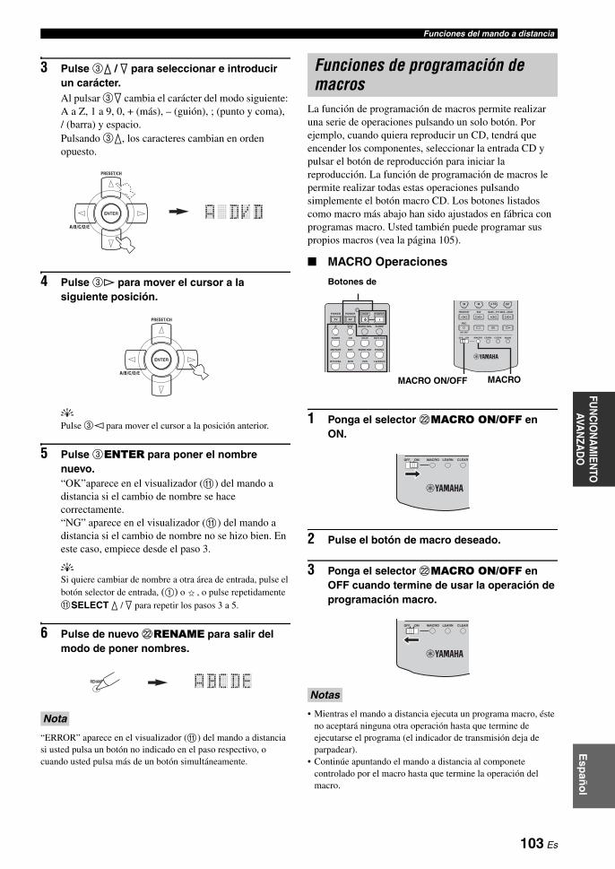
Funciones del mando a distanciaFU
NC
ION
AM
IENTO
AVA
NZA
DO
Esp
año
l
3 Pulse 3k / n para seleccionar e introducir un carácter.Al pulsar 3n cambia el carácter del modo siguiente: A a Z, 1 a 9, 0, + (más), – (guión), ; (punto y coma), / (barra) y espacio. Pulsando 3k, los caracteres cambian en orden opuesto.
4 Pulse 3h para mover el cursor a la siguiente posición.
yPulse 3l para mover el cursor a la posición anterior.
5 Pulse 3ENTER para poner el nombre nuevo.“OK”aparece en el visualizador (A) del mando a distancia si el cambio de nombre se hace correctamente.“NG” aparece en el visualizador (A) del mando a distancia si el cambio de nombre no se hizo bien. En este caso, empiece desde el paso 3.
ySi quiere cambiar de nombre a otra área de entrada, pulse el botón selector de entrada, (1) o , o pulse repetidamente ASELECT k / n para repetir los pasos 3 a 5.
6 Pulse de nuevo LRENAME para salir del modo de poner nombres.
“ERROR” aparece en el visualizador (A) del mando a distancia si usted pulsa un botón no indicado en el paso respectivo, o cuando usted pulsa más de un botón simultáneamente.
La función de programación de macros permite realizar una serie de operaciones pulsando un solo botón. Por ejemplo, cuando quiera reproducir un CD, tendrá que encender los componentes, seleccionar la entrada CD y pulsar el botón de reproducción para iniciar la reproducción. La función de programación de macros le permite realizar todas estas operaciones pulsando simplemente el botón macro CD. Los botones listados como macro más abajo han sido ajustados en fábrica con programas macro. Usted también puede programar sus propios macros (vea la página 105).
MACRO Operaciones
1 Ponga el selector LMACRO ON/OFF en ON.
2 Pulse el botón de macro deseado.
3 Ponga el selector LMACRO ON/OFF en OFF cuando termine de usar la operación de programación macro.
• Mientras el mando a distancia ejecuta un programa macro, éste no aceptará ninguna otra operación hasta que termine de ejecutarse el programa (el indicador de transmisión deja de parpadear).
• Continúe apuntando el mando a distancia al componete controlado por el macro hasta que termine la operación del macro.
Nota
ENTER
A/B/C/D/E
PRESET/CH
ENTER
A/B/C/D/E
PRESET/CH
RENAME
Funciones de programación de macros
Notas
AVTV
ENT+1009
DTV/CBL VCRDVR V-AUX/DOCK
TUNER CD CD-R MULTI CH IN
POWER POWER POWERSTANDBY
SLEEPAUDIO SEL
DVD BD/HD DVD PHONOMD/TAPE
ONOFF CLEARLEARN RENAMEMACRO
REC
DISC SKIP
FREQ/TEXT EON MODE – PTY SEEK – START
MACROMACRO ON/OFF
Botones de
ONOFF CLEARLEARNMACRO
ONOFF CLEARLEARNMACRO
103 Es

Funciones del mando a distancia
Funciones macro predeterminadas
*1 Puede encender algunos componentes (incluyendo componentes Yamaha) conectados a esta unidad conectándolos al AC OUTLET(S) del panel trasero de esta unidad. El control de la alimentación tal vez no se sincronice con esta unidad dependiendo del componente. Para conocer detalles, consulte las instrucciones del componente conectado.
*2 Cuando el código de mando a distancia para su TV se prepare para DTV/CBL o PHONO (vea la página 99), usted podrá encender su TV sin seleccionar una fuente de entrada. El código de mando a distancia preparado para DTV tiene prioridad sobre el preparado para PHONO.
*3 Cuando se selecciona TUNER como fuente de entrada, esta unidad recibe la última emisora sintonizada antes de poner la unidad en el modo de espera.
*4 La reproducción se puede iniciar para cualquier grabadora MD, reproductor CD, grabadora CD, reproductor DVD, reproductor Blu-ray Disc, reproductor HD DVD o grabadora DVD que sea compatible con el mando a distancia de Yamaha. Cuando se utilicen macros para controlar otros componentes, necesitará programar de antemano el botón de reproducción del área de entrada de ese componente (vea la página 101) o poner el código de mando a distancia (vea la página 99).
Pulsación de un botón de macro
Para transmitir automáticamente estas señales en ordenPrimero Segundo Tercero
— —
—
— —
—
(*1)
—
(Área CD) (*4)
(Área CD-R) (*4)
—
(Área MD/TAPE) (*4)
(Área DVD) (*4)
(Área BD/HD DVD) (*4)
—
—
(Área DVR) (*4)
(Área VCR) (*4)
—
STANDBY STANDBY
POWER POWER (*1)TV
POWER (*2)
POWER
POWER
TUNER
POWER
TUNER (*3)
CD CD
CD-R CD-R
MULTI CH IN MULTI CH IN
MD/TAPE MD/TAPE
DVD DVD
BD/HD DVD BD/HD DVD
PHONO PHONO
DTV/CBL DTV/CBL
DVR DVR
VCR VCR
V-AUX/DOCK V-AUX/DOCK
104 Es

Funciones del mando a distanciaFU
NC
ION
AM
IENTO
AVA
NZA
DO
Esp
año
l
Programación de operaciones macroPuede programar su propio macro y utilizar la función de programación macro para transmitir varios comandos de mando a distancia en orden pulsando un solo botón. Asegúrese de preparar los códigos del mando a distancia o realizar operaciones de aprendizaje antes de programar el macro.
• El macro predeterminado no se cancela cuando se programa un macro nuevo para un botón. El macro predeterminado se puede utilizar de nuevo cuando se borra el macro programado.
• No es posible añadir una señal nueva (paso macro) al macro predeterminado. La programación de un macro cambia todo el contenido del macro.
• No le recomendamos programar operaciones continuas como, por ejemplo, el control del volumen en un macro.
1 Ponga el selector del modo de operación en CAMP o CSOURCE y luego pulse LMACRO usando un bolígrafo u objeto similar.“MCR ?” aparece en el visualizador (A) del mando a distancia.
Si no completa cada uno de los pasos siguientes antes de pasar 30 segundos, el modo de programación de macro se cancelará automáticamente. En este caso, empiece desde el paso 1.
2 Pulse el botón LMACRO que quiera utilizar para controlar el macro.El nombre del botón de macro (ej., “M;DVD”) y el nombre del componente seleccionado (ej., “DVD”) aparecen alternativamente en el visualizador (A) del mando a distancia.
“AGAIN” aparece en el visualizador (A) si usted pulsa un botón que no es un botón macro.
3 Pulse en orden los botones para las funciones que usted quiera incluir en la operación macro.Puede preparar hasta 10 pasos (10 funciones). Después de establecer 10 pasos, aparece “FULL” y el mando a distancia sale automáticamente del modo macro.
Ejemplo:Ponga la fuente de entrada en DVD → Active el reproductor DVD → Ajuste el temporizador para dormir
Paso 1 (“MCR 1”): Pulse DVD.Paso 2 (“MCR 2”): Pulse AV POWER.Paso 3 (“MCR 3”): Pulse SLEEP.
Para cambiar el área de entrada seleccionada, pulse ASELECT k / n. Al pulsar los botones selectores de entrada
se programará un paso macro, mientras que ASELECT k / n sólo cambia el área de entrada seleccionada.
4 Mantenga pulsado LMACRO utilizando un bolígrafo u objeto similar cuando el orden de operaciones que quiera programar haya terminado.
“ERROR” aparece en el visualizador (A) si usted pulsa más de un botón simultáneamente.
Notas
Nota
MACRO
TV
SOURCE
AMP
TV
SOURCE
AMP
o
DTV/CBL VCRDVR V-AUX/DOCK
TUNER CD CD-R MULTI CH IN
DVD BD/HD DVD PHONOMD/TAPE
POWERSTANDBY
Nota
Nota
Nota
AVTV
SELECT
DTV/CBL VCRDVR V-AUX/DOCK
TUNER CD CD-R MULTI CH IN
POWER POWER POWERSTANDBY
SLEEPAUDIO SEL
DVD BD/HD DVD PHONOMD/TAPE
1
2
3
Indica el número de pasos macros que usted ha introducido
Parpadea alternativamente para que usted pueda establecer el paso siguiente
105 Es

Funciones del mando a distancia
Puede cancelar todos los cambios hechos en cada juego de funciones, como las funciones aprendidas, los macros, los nombres de las áreas de entrada que han cambiado de nombre y los códigos del mando a distancia ajustados.
Cancelación de juegos de funciones
1 Ponga el selector del modo de operación en CAMP o CSOURCE y luego pulse LCLEAR usando un bolígrafo u objeto similar.“CLEAR” aparece en el visualizador (A).
Si no completa cada uno de los pasos siguientes antes de pasar 30 segundos, el modo de cancelación se cancelará automáticamente. En este caso, empiece desde el paso 1.
2 Pulse 3k / n para seleccionar el modo de borrado.
L;CD (etc.) (L; nombre del área de entrada)Cancela todas las funciones aprendidas en el área de entrada respectiva. El nombre de un componente se muestra después de un punto y coma (;). Pulse un botón selector de entrada para seleccionar el área de entrada.
L;AMP Cancela todas las funciones aprendidas para las funciones de amplificdor de esta unidad.
L;ALL Cancela todas las funciones aprendidas.M;ALL Cancela todos los macros programados.RNAME Cancela todos los nombres de las fuentes cuyos
nombres han sido cambiados.FCTRY Cancela todas las funciones del mando a
distancia y éste recupera los ajustes de fábrica.
3 Mantenga pulsado de nuevo LCLEAR durante más de 3 segundos.“WAIT” aparece en el visualizador (A). Si la cancelación se hace bien, “C;OK” aparece en el visualizador (A) del mando a distancia.
yUna vez cancelada una función aprendida para un botón, el botón vuelve al ajuste de fábrica (o al ajuste del fabricante si usted ha puesto códigos de mando a distancia).
• “L;ALL” y “FCTRY” pueden tardar unos 30 segundos en completarse.
• “C;NG” aparece en el visualizador (A) si la cancelación no se hizo correctamente. En este caso, empiece desde el paso 2.
• “ERROR” aparece en el visualizador (A) si usted pulsa un botón no indicado en el paso respectivo, o si usted pulsa más de un botón simultáneamente.
4 Pulse de nuevo LCLEAR para salir.
Cancelación de una función aprendidaPuede cancelar la función aprendida para cierto botón en cada área de control.
1 Ponga el selector del modo de operación en CAMP o CSOURCE y luego pulse un botón selector de entrada (1), o para seleccionar el área de entrada que contiene la función que usted quiere borrar.El nombre del componente seleccionado aparece en el visualizador.
Borrado de configuraciones
Nota
CLEAR
TV
SOURCE
AMP
TV
SOURCE
AMP
o
Notas
CLEAR
DTV/CBL VCRDVR V-AUX/DOCK
TUNER CD CD-R MULTI CH IN
DVD BD/HD DVD PHONOMD/TAPE
TV
SOURCE
AMP
TV
SOURCE
AMP
o
106 Es

Funciones del mando a distanciaFU
NC
ION
AM
IENTO
AVA
NZA
DO
Esp
año
l
2 Pulse LLEARN utilizando un bolígrafo u objeto similar.“LEARN” y el nombre del componente seleccionado (ej. “DVD”) aparecen alternativamente en el visualizador.
• No lo pulse y lo mantenga pulsado LLEARN. Si lo mantiene pulsado durante más de 3 segundos, el mando a distancia se pondrá en el modo de ajuste de códigos de mando a distancia.
• Si no completa cada uno de los pasos siguientes antes de pasar 30 segundos, el modo de aprendizaje se cancelará automáticamente. En este caso, empiece desde el paso 2.
3 Mantenga pulsado LCLEAR utilizando un bolígrafo u objeto similar, y luego pulse el botón que desee cancelar durante unos 3 segundos.“C;OK” aparece en el visualizador (A) si la cancelación se hizo correctamente. Una vez que “C;OK” aparezca en el visualizador del mando a distancia, suelte el bolígrafo u objeto similar usado para pulsar LCLEAR para salir del modo de cancelación. El mando a distancia vuelve al modo de aprendizaje.
y• Si desea cancelar otra función, repita el paso 3.• Si desea cancelar continuamente otra función para otro
componente, pulse ASELECT k / n para seleccionar el área de entrada y luego repita el paso 3.
• Una vez que cancela una función aprendida, el botón vuelve al ajuste de fábrica (o al ajuste de fabricante si usted ha establecido códigos de mando a distancia).
4 Pulse de nuevo LLEARN para salir.
• “C;NG” aparece en el visualizador (A) del mando a distancia si la cancelación no se hizo bien. En este caso, empiece desde el paso 2.
• “ERROR” aparece en el visualizador (A) si usted pulsa más de un botón simultáneamente.
Cancelación de una función macroPuede cancelar la función programada para cierto botón de macro.
1 Ponga el selector del modo de operación en CAMP o CSOURCE y luego pulse LMACRO usando un bolígrafo u objeto similar.“MCR ?” aparece en el visualizador (A) del mando a distancia.
Si no completa cada uno de los pasos siguientes antes de pasar 30 segundos, el modo de programación de macro se cancelará automáticamente. En este caso, empiece desde el paso 1.
2 Mantenga pulsado LCLEAR utilizando un bolígrafo u objeto similar, y luego pulse el botón de macro que desee cancelar durante unos 3 segundos.“C;OK” aparece en el visualizador (A) del mando a distancia si la cancelación se hizo correctamente.
y• Si desea cancelar otra función, repita el paso 2.• Una vez que cancela una función programada, el botón
vuelve al ajuste de fábrica (o al ajuste de fabricante si usted ha establecido códigos de mando a distancia).
3 Pulse de nuevo LMACRO para salir del modo de programación.
• “C;NG” aparece en el visualizador (A) del mando a distancia si la cancelación no se hizo bien. En este caso, empiece desde el paso 2.
• “ERROR” aparece en el visualizador (A) del mando a distancia si usted pulsa más de un botón simultáneamente.
Notas
Notas
LEARN
CLEARLEARN RENAME
MODE – PTY SEEK – START
Nota
Notas
MACRO
TV
SOURCE
AMP
TV
SOURCE
AMP
o
ONOFF CLEARLEARN RENAMEMACRO
DTV/CBL VCRDVR V-AUX/DOCK
DVD BD/HD DVD PHONOMD/TAPE
107 Es

Esta unidad le permite configurar un sistema de audio para múltiples zonas. La función de configuración de múltiples zonas le permite preparar esta unidad para reproducir fuentes de entrada diferentes en la habitación principal, en una segunda zona (Zone 2) y en una tercera zona (Zone 3). Con el mando a distancia puede controlar esta unidad desde la segunda o la tercera zona.
Para usar las funciones de múltiples zonas de esta unidad necesitará el equipo adicional siguiente:• Un receptor de señales infrarrojas en Zone 2 y/o Zone 3.• Un emisor de señales infrarrojas en la zona principal. Este emisor transmite las señales infrarrojas desde el mando a
distancia de Zone 2 y/o Zone 3 a la zona principal (a un reproductor CD o DVD, por ejemplo).• Un amplificador y altavoces para Zone 2 y/o Zone 3.
y• Si quiere usar los amplificadores internos de esta unidad no necesita un amplificador ni altavoces extra para Zone 2 y/o Zone 3.• Como hay muchas formas de conectar y utilizar esta unidad en una instalación de múltples zonas, le recomendamos consultar con el centro de
servicio o concesionario Yamaha autorizado más cercano para hacer las conexiones Zone 2 y Zone 3 que mejor satisfagan sus requerimientos.
Utilización de amplificadores externosPara usar un amplificador externo en Zone 2 o Zone 3, conecte ese amplificador a los jacks ZONE OUT y seleccione “EXT” en “AMP” o (vea la página 91).
• Para evitar ruidos inesperados, NO use la función Zone 2/Zone 3 con CDs codificados con DTS.• Ajuste el volumen Zone 2/Zone 3 utilizando el amplificador en la Zone 2/Zone 3 cuando “VOLUME” se pone en “FIX”
(vea la página 92).
Uso de la configuración multizona
Conecte el componente fuente a los jacks de entrada de audio analógico de esta unidad para reproducir la fuente en Zone 2 o Zone 3. Esta unidad no envía a los jacks ZONE OUT las señales de audio introducidas por los jacks DIGITAL INPUT y HDMI.
Conexión de los componentes Zone 2 y Zone 3
Notas
OUTOUT IN
REMOTE
IN
REMOTE
OUT IN
REMOTE REMOTE
Esta unidad Componente Yamaha
Componente Yamaha
Receptor de señales infrarrojas
MAIN
ZONE 2
ZONE 3
Receptor de señales infrarrojas
Reproductor DVD , etc.
Amplificador
Mando a distancia
Receptor de señales infrarrojas
Amplificador
Mando a distancia
Receptor de señales infrarrojas
Segunda zona(Zone 2)
Tercera zona (Zone 3)Zona principal
Esta unidad
Desde los jacks ZONE OUT (ZONE 2)
Desde los jacks ZONE OUT (ZONE 3)
Al jack REMOTE INAl jack REMOTE INDesde el jack REMOTE OUT
Señales de audio analógico solamente
108 Es
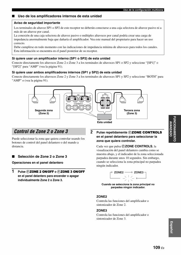
Uso de la configuración multizonaFU
NC
ION
AM
IENTO
AVA
NZA
DO
Esp
año
l
Uso de los amplificadores internos de esta unidad
Si quiere usar un amplificador interno (SP1 o SP2) de esta unidadConecte directamente los altavoces Zone 2 o Zone 3 a los terminales de altavoces SP1 o SP2 y seleccione “[SP1]” o “[SP2]” para “AMP” (vea la página 91).
Si quiere usar ambos amplificadores internos (SP1 y SP2) de esta unidadConecte directamente los altavoces Zone 2 y Zone 3 a los terminales de altavoces SP1 y SP2 y seleccione “BOTH” para “AMP” o (vea la página 91).
Puede seleccionar la zona que quiera controlar usando los botones de control del panel delantero o del mando a distancia.
Selección de Zone 2 o Zone 3
Operaciones en el panel delantero
1 Pulse PZONE 2 ON/OFF o PZONE 3 ON/OFF en el panel delantero para encender o apagar individualmente Zone 2 o Zone 3.
2 Pulse repetidamente PZONE CONTROLS en el panel delantero para seleccionar la zona que quiera controlar.
Cada vez que pulsa PZONE CONTROLS, la visualización del panel delantero cambia como se muestra abajo, y el indicador de la zona seleccionada parpadea durante unos 10 segundos. Sin embargo, cuando se selecciona la zona principal no parpadea ningún indicador.
ZONE2Controla las funciones del amplificador o sintonizador de Zone 2.
ZONE3Controla las funciones del amplificador o sintonizador de Zone 3.
Aviso de seguridad importante
Los terminales de altavoz SP1 o SP2 de este receptor no deberán conectarse a una caja selectora de altavoz pasivo ni a más de un altavoz por canal.La conexión de una caja selectora de altavoz pasivo o múltiples altavoces por canal podría crear una carga de impedancia anormalmente baja que dañaría el amplificador. Vea este manual del propietario para hacer un uso correcto.Debe cumplirse en todo momento con las indicaciones de impedancia mínima de altavoces para todos los canales. Esta información se encuentra en el panel posterior de su receptor.
R L
+
–
SP2
SINGLE
R L+–+ –
BI-AMPSURROUND BACK/
PRESENCE/ZONE 2/ZONE 3ZONE 2/ZONE 3
R L
SP1
+–+ –
Tercera zona (Zone 3)
Esta unidad
Segunda zona (Zone 2)
Control de Zone 2 o Zone 3
ZONE2 ZONE3
Cuando se selecciona la zona principal no parpadea ningún indicador.
109 Es

Uso de la configuración multizona
y• Deberá completar este paso dentro de 10 segundos
mientras la zona seleccionada parpadea en el visualizador del panel delantero. De lo contrario, el modo de zona seleccionado actualmente se cancelará de forma automática. En este caso, pulse de nuevo PZONE CONTROLS.
• El ajuste inicial es ZONE2 cuando Zone 2 y Zone 3 están encendidos.
3 Consulte “Selección de la fuente de entrada de Zone 2 o Zone 3”, “Ajuste del nivel del sonido de Zone 2 o Zone 3”, “Ajuste del balance del nivel de altavoces en Zone 2 o Zone 3” o “Ajuste de la calidad tonal de Zone 2 o Zone 3” en la página 111 para realizar más operaciones.
Operaciones en el mando a distancia
1 Ponga el selector del modo de operación en CAMP y luego pulse repetidamente ASELECT k para seleccionar la zona que quiera controlar.“ZONE 2” o “ZONE 3” se muestra en el visualizador (A) del mando a distancia.
2 Consulte “Selección de la fuente de entrada de Zone 2 o Zone 3”, “Ajuste del nivel del sonido de Zone 2 o Zone 3”, “Ajuste del balance del nivel de altavoces en Zone 2 o Zone 3” o “Ajuste de la calidad tonal de Zone 2 o Zone 3” en la página 111 para realizar más operaciones.
3 Pulse ASELECT k / n para salir del modo Zone 2/Zone 3.
Apagado o encendido de Zone 2 y/o Zone 3 con el mando a distancia
8POWER y 7STANDBY en el mando a distancia funcionan de forma diferente dependiendo de la zona seleccionada que aparece en el visualizador (A) del mando a distancia.• Cuando seleccione el modo de la zona principal, Zone
2 o Zone 3, usted podrá, individualmente, encender la zona principal , Zone 2 o Zone 3 o ponerlas en el modo de espera.
• Cuando se selecciona el modo completo, al pulsar 8POWER se enciende simultáneamente la zona principal , Zone 2 y Zone 3, y al pulsar 7STANDBY éstas se ponen simultáneamente en el modo de espera.
• Cuando el mando a distancia está en el modo de zona principal, “MAIN” aparece durante unos pocos segundos cuando se pulsa 8POWER o 7STANDBY.
• “ALL” aparece en el visualizador (A) del mando a distancia sólo cuando se pulsa ASELECT n.
SELECT
TV
SOURCE
AMP
o
Modo de control Visualizador(A) POWER y
STANDBY
Modo de zona principal
Nombre del área de entrada seleccionada
Enciende solamente la zona principal o la pone en el modo de espera.
Modo Zone 2“ZONE 2” o “2; nombre del área de entrada seleccionada”
Enciende Zone 2 o la pone en el modo de espera.
Modo Zone 3“ZONE 3” o “3; nombre del área de entrada seleccionada”
Enciende Zone 3 o la pone en el modo de espera.
Modo completo
“ALL”
8POWER: enciende la zona principal , Zone 2 y Zone 3.7STANDBY: pone la zona principal, Zone 2 y Zone 3 en el modo de espera.
Notas
110 Es

Uso de la configuración multizonaFU
NC
ION
AM
IENTO
AVA
NZA
DO
Esp
año
l
Selección de la fuente de entrada de Zone 2 o Zone 3
Gire el selector CINPUT del panel delantero (o ponga el selector del modo de operación en CAMP y luego pulse uno de los botones selectores de entrada del mando a distancia) para seleccionar la fuente de entrada de la zona deseada.Si el mando a distancia se usa para seleccionar la fuente de entrada, “2: nombre de la fuente de entrada seleccionada” o “3: nombre de la fuente de entrada seleccionada” se muestra en el visualizador (A) del mando a distancia cuando se selecciona Zone 2 o Zone 3 respectivamente.
• Seleccione “TUNER” como fuente de entrada para usar las funciones de sintonización de FM/AM en la zona seleccionada. Para conocer detalles de las operaciones de sintonización de FM/AM, vea “Sintonización de FM/AM” en la página 54.
• Seleccione “V-AUX” como fuente de entrada para reproducir fuentes en el iPod acoplado a un acoplador universal Yamaha iPod (como el YDS-10 vendido separadamente) en la zona seleccionada. Sólo puede controlar iPod en el modo remoto sencillo (vea la página 61).
Las fuentes de entrada se comparten entre todas las zonas. No puede seleccionar simultáneamente la misma fuente de entrada para múltiples zonas.
yDeberá completar este paso dentro de 10 segundos mientras la zona seleccionada parpadea en el visualizador del panel delantero. De lo contrario, el modo de zona seleccionado actualmente se cancelará de forma automática. En este caso, pulse de nuevo PZONE CONTROLS en el panel delantero.
Ajuste del nivel del sonido de Zone 2 o Zone 3
Gire QVOLUME en el panel delantero (o pulse BVOLUME +/– en el mando a distancia) para ajustar el nivel de sonido de la zona seleccionada.
yPulse DMUTE en el mando a distancia para silenciar la salida de sonido a la zona seleccionada.
Cuando usa amplificadores externos en Zone 2 o Zone 3, BVOLUME +/– sólo se puede usar cuando “VOLUME” está puesto en “VAR” en “ZONE SET” (vea la página 92).
Ajuste del balance del nivel de altavoces en Zone 2 o Zone 3
Pulse repetidamente ETONE CONTROL para seleccionar “BALANCE” y luego gire NPROGRAM en el panel delantero para ajustar el balancde del nivel de los altavoces derecho e izquierdo de la zona seleccionada.
Ajuste de la calidad tonal de Zone 2 o Zone 3
Ponga el selector del modo de operación en CAMP y luego pulse CH +/– en el mando a distancia para ajustar la respuesta de alta frecuencia (TREBLE) o pulse TV VOL +/– para ajustar la respuesta de baja frecuencia (BASS).
yPuede ajustar la calidad tonal Zone 2 o Zone 3 usando ETONE CONTROL en el panel delantero. Para conocer detalles, vea “Ajuste de la calidad tonal” en la página 52.
Compruebe que “ZONE 2” o “ZONE 3” se visualice en el visualizador (A) del mando a distancia antes de ajustar la calidad tonal de la zona correspondiente (vea la página 110).
Haga las operaciones siguientes después de activar el modo de operación Zone 2 o Zone 3.
Nota
Nota
Nota
–
+TV VOL
+
–CH
TV
SOURCE
AMP
TREBLE
BASS
111 Es

Uso de la configuración multizona
Uso del mando a distancia de Zone 2/Zone 3(excepto para el modelo de Europa)
Usando el mando a distancia Zone 2/Zone 3 puede controlar las funciones Zone 2 o Zone 3. Primero, ponga en las posiciones correctas los conmutadores ID1/ID2 y ZONE 2/ZONE 3.
Control de la función del amplificador
1 Botones selectores de entradaSeleccionan la fuente de entrada deseada para la zona de control.
4 Conmutador ID1/ID2Cambia la identificación del mando a distancia entre ID1 y ID2 (vea la página 114).
5 POWEREnciende Zone 2 o Zone 3.
Este botón sólo funciona cuando se pulsa AMASTER ON/OFF del panel delantero hasta la posición ON.
6 STANDBYPone Zone 2 o Zone 3 en el modo de espera.
Este botón sólo funciona cuando se pulsa AMASTER ON/OFF del panel delantero hasta la posición ON.
7 VOLUME +/–Aumenta o disminuye el nivel del sonido de Zone 2 o Zone 3.
8 MUTESilencia el sonido de Zone 2 o Zone 3. Púlselo de nuevo para reponer la salida de audio al nivel de sonido anterior.
9 Conmutador ZONE 2/ZONE 3Cambia entre el modo de operación de Zone 2 y Zone 3.
Control de la función del sintonizador (vea la página 54)
2 PRESET k / nSelecciona uno de los 8 números de emisoras presintonizadas (1 a 8) cuando se visualizan los dos puntos (:) en el visualizador del panel delantero (vea la página 56).
3 A/B/C/D/ESelecciona uno de los grupos de emisoras presintonizadas (A a E) (vea la página 55).
Nota
TUNER CD CD-R
MD/TAPE DVD BD/HD DVD PHONO
DTV/CBL VCR V-AUX/DOCKDVR
POWER
STANDBY
A/B/C/D/E
PRESET VOLUME
ZONE 3ZONE 2ID2ID1
MUTE
4 9
8
7
6
5
1
2
3
Nota
Seleccione “TUNER” como fuente de entrada de la zona de control para usar las funciones siguientes.
112 Es
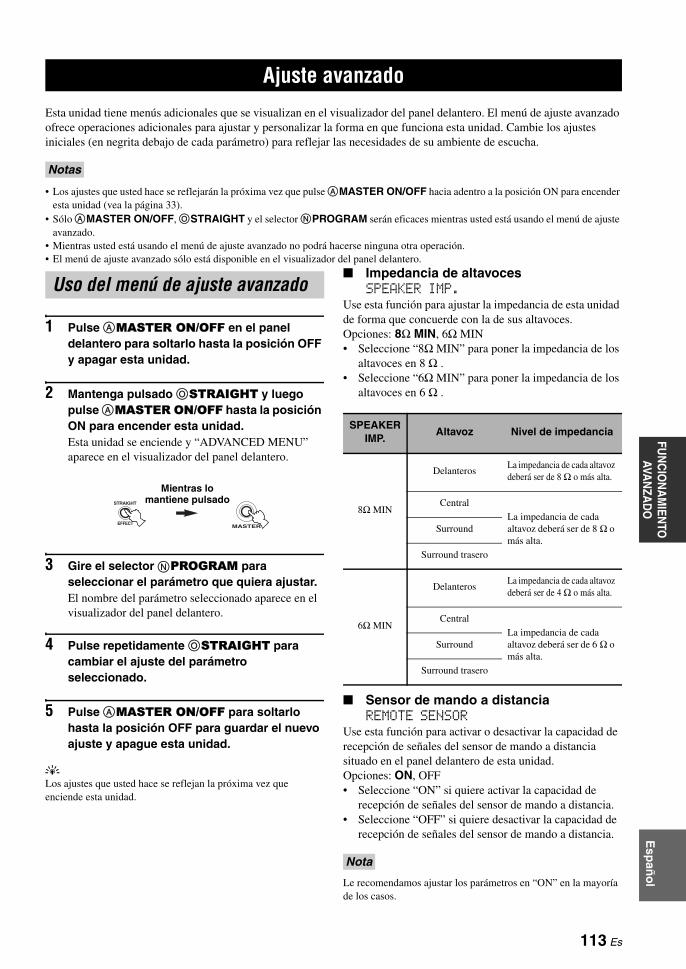
Esp
año
lFU
NC
ION
AM
IENTO
AVA
NZA
DO
Esta unidad tiene menús adicionales que se visualizan en el visualizador del panel delantero. El menú de ajuste avanzado ofrece operaciones adicionales para ajustar y personalizar la forma en que funciona esta unidad. Cambie los ajustes iniciales (en negrita debajo de cada parámetro) para reflejar las necesidades de su ambiente de escucha.
• Los ajustes que usted hace se reflejarán la próxima vez que pulse AMASTER ON/OFF hacia adentro a la posición ON para encender esta unidad (vea la página 33).
• Sólo AMASTER ON/OFF, OSTRAIGHT y el selector NPROGRAM serán eficaces mientras usted está usando el menú de ajuste avanzado.
• Mientras usted está usando el menú de ajuste avanzado no podrá hacerse ninguna otra operación.• El menú de ajuste avanzado sólo está disponible en el visualizador del panel delantero.
1 Pulse AMASTER ON/OFF en el panel delantero para soltarlo hasta la posición OFF y apagar esta unidad.
2 Mantenga pulsado OSTRAIGHT y luego pulse AMASTER ON/OFF hasta la posición ON para encender esta unidad.Esta unidad se enciende y “ADVANCED MENU” aparece en el visualizador del panel delantero.
3 Gire el selector NPROGRAM para seleccionar el parámetro que quiera ajustar.El nombre del parámetro seleccionado aparece en el visualizador del panel delantero.
4 Pulse repetidamente OSTRAIGHT para cambiar el ajuste del parámetro seleccionado.
5 Pulse AMASTER ON/OFF para soltarlo hasta la posición OFF para guardar el nuevo ajuste y apague esta unidad.
yLos ajustes que usted hace se reflejan la próxima vez que enciende esta unidad.
Impedancia de altavocesSPEAKER IMP.
Use esta función para ajustar la impedancia de esta unidad de forma que concuerde con la de sus altavoces.Opciones: 8Ω MIN, 6Ω MIN• Seleccione “8Ω MIN” para poner la impedancia de los
altavoces en 8 Ω .• Seleccione “6Ω MIN” para poner la impedancia de los
altavoces en 6 Ω .
Sensor de mando a distanciaREMOTE SENSOR
Use esta función para activar o desactivar la capacidad de recepción de señales del sensor de mando a distancia situado en el panel delantero de esta unidad.Opciones: ON, OFF• Seleccione “ON” si quiere activar la capacidad de
recepción de señales del sensor de mando a distancia.• Seleccione “OFF” si quiere desactivar la capacidad de
recepción de señales del sensor de mando a distancia.
Le recomendamos ajustar los parámetros en “ON” en la mayoría de los casos.
Ajuste avanzado
Notas
Uso del menú de ajuste avanzado
EFFECT
STRAIGHT
MASTER
Mientras lo mantiene pulsado
SPEAKER IMP.
Altavoz Nivel de impedancia
8Ω MIN
DelanterosLa impedancia de cada altavoz deberá ser de 8 Ω o más alta.
Central
La impedancia de cada altavoz deberá ser de 8 Ω o más alta.
Surround
Surround trasero
6Ω MIN
DelanterosLa impedancia de cada altavoz deberá ser de 4 Ω o más alta.
Central
La impedancia de cada altavoz deberá ser de 6 Ω o más alta.
Surround
Surround trasero
Nota
113 Es

Ajuste avanzado
RS-232C acceso en el modo de esperaRS-232C STANDBY
Use esta función para que esta unidad transmita datos a través de la interfaz RS-232C cuando esta unidad esté en el modo de espera.Opciones: YES, NOAjuste inicial:[Modelos de EE.UU. y Canadá]: YES[Otros modelos]: NO• Seleccione “YES” para ajustar esta unidad para
transmitir datos a través de la interfaz RS-232C.• Seleccione “NO” para ajustar esta unidad para no
transmitir datos a través de la interfaz RS-232C.
ID AMP de mando a distanciaRC AMP ID
Use esta función para poner la AMP ID de esta unidad para que la reconozca el mando a distancia.Opciones: ID1, ID2• Seleccione “ID1” cuando el código de librería AMP ID
del mando a distancia se ponga en “2001”.• Seleccione “ID2” cuando el código de librería AMP ID
del mando a distancia se ponga en “2002”.
Puesta del código AMP ID del mando a distancia
1 Ponga el selector del modo de operación en CAMP o CSOURCE.
2 Mantenga pulsado LLEARN durante unos 3 segundos con un bolígrafo u objeto similar y luego pulse repetidamente 3l / h hasta que “L;AMP” aparezca en el visualizador (A) del mando a distancia.
• Asegúrese de mantener pulsado LLEARN durante un mínimo de 3 segundos ya que de lo contrario empezará el proceso de aprendizaje.
• Si no completa cada uno de los pasos siguientes antes de pasar 30 segundos, el modo de ajuste se cancelará automáticamente. En este caso, empiece desde el paso 2.
3 Pulse 3ENTER.El código de cuatro dígitos establecido para el área de entrada seleccionada aparece en el visualizador (A).
4 Pulse los botones numéricos (5) para introducir el código AMP ID de mando a distancia de cuatro dígitos para el área de entrada que quiera utilizar.
*1 El ajuste de mando a distancia.*2 El ajuste de esta unidad.
5 Pulse 3ENTER para poner el número.“OK” aparece en el visualizador (A) si el ajuste se hizo bien.“NG” aparece en el visualizador (A) si el ajuste se hizo mal. En este caso, empiece desde el paso 2.
6 Pulse de nuevo LLEARN para salir del modo de preparación.
ID TUNER de mando a distanciaRC TUNER ID
Use esta función para poner la TUNER ID de esta unidad para que la reconozca el mando a distancia.Opciones: ID1, ID2• Seleccione “ID1” cuando el código de librería TUNER
ID del mando a distancia se ponga en “2602”.• Seleccione “ID2” cuando el código de librería TUNER
ID del mando a distancia se ponga en “2603”.
Vea la página 113 para la operación del menú de ajuste avanzado.
Notas
LEARN
ENTER
A/B/C/D/E
PRESET/CH
Código AMP ID del mando a distancia *1
Función RC AMP ID*2
2001(ajuste inicial)
Controla esta unidad usando el código predeterminado.
ID1 (ajuste inicial)
2002Controla esta unidad usando un código alternativo.
ID2
ENTER
A/B/C/D/E
PRESET/CH
LEARN
114 Es
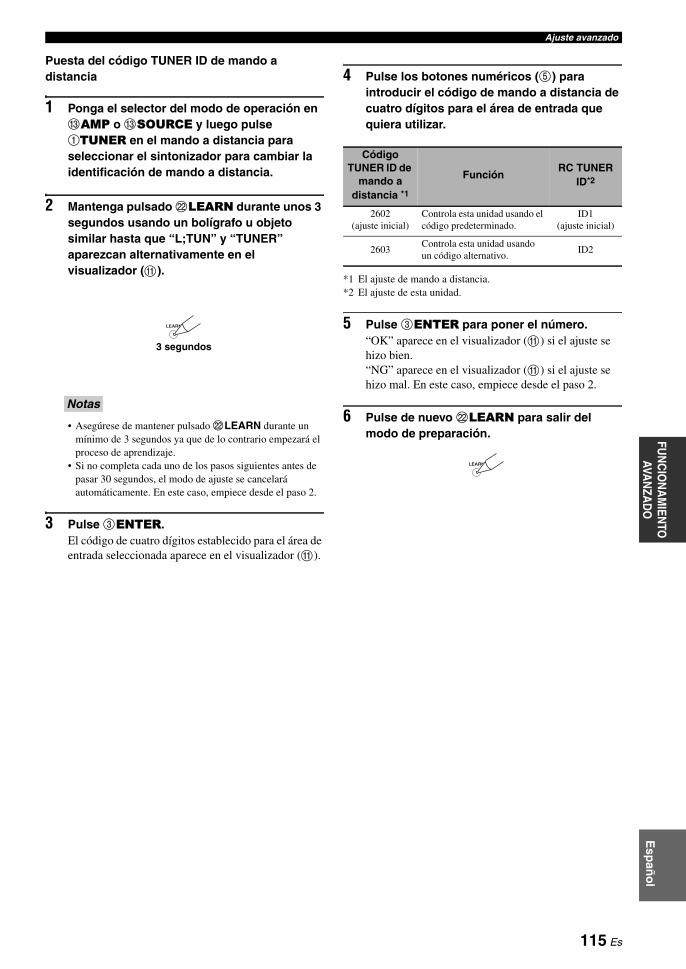
Ajuste avanzadoFU
NC
ION
AM
IENTO
AVA
NZA
DO
Esp
año
l
Puesta del código TUNER ID de mando a distancia
1 Ponga el selector del modo de operación en CAMP o CSOURCE y luego pulse 1TUNER en el mando a distancia para seleccionar el sintonizador para cambiar la identificación de mando a distancia.
2 Mantenga pulsado LLEARN durante unos 3 segundos usando un bolígrafo u objeto similar hasta que “L;TUN” y “TUNER” aparezcan alternativamente en el visualizador (A).
• Asegúrese de mantener pulsado LLEARN durante un mínimo de 3 segundos ya que de lo contrario empezará el proceso de aprendizaje.
• Si no completa cada uno de los pasos siguientes antes de pasar 30 segundos, el modo de ajuste se cancelará automáticamente. En este caso, empiece desde el paso 2.
3 Pulse 3ENTER.El código de cuatro dígitos establecido para el área de entrada seleccionada aparece en el visualizador (A).
4 Pulse los botones numéricos (5) para introducir el código de mando a distancia de cuatro dígitos para el área de entrada que quiera utilizar.
*1 El ajuste de mando a distancia.*2 El ajuste de esta unidad.
5 Pulse 3ENTER para poner el número.“OK” aparece en el visualizador (A) si el ajuste se hizo bien.“NG” aparece en el visualizador (A) si el ajuste se hizo mal. En este caso, empiece desde el paso 2.
6 Pulse de nuevo LLEARN para salir del modo de preparación.
Notas
LEARN
3 segundos
Código TUNER ID de
mando a distancia *1
FunciónRC TUNER
ID*2
2602 (ajuste inicial)
Controla esta unidad usando el código predeterminado.
ID1 (ajuste inicial)
2603Controla esta unidad usando un código alternativo.
ID2
LEARN
115 Es

Ajuste avanzado
Paso de frecuencias del sintonizador TUNER FRQ STEP(Modelos de Asia y General solamente)
Use esta función para establecer el paso de frecuencias del sintonizador según la separación de frecuencias de su zona.Opciones: AM10/FM100, AM9/FM50• Seleccione “AM10/FM100” para América del norte,
Centroamérica y Sudamérica.• Seleccione “AM9/FM50” para todas las demás áreas.
Ajuste de biamplificador BI-AMPUse esta función para activar o desactivar la función de biamplificador (vea la página 19).Opciones: ON, OFF• Seleccione “ON” si quiere activar la función de
biamplificador.• Seleccione “OFF” si quiere desactivar la función de
biamplificador.
Cuando “BI-AMP” se ponga en “ON”, los terminales SURROUND BACK no se podrán utilizar para conectar altavoces surround traseros porque los terminales SURROUND BACK ya estarán sido usados para la conexión de biamplificador (vea la página 19).
Inicialización de los parámetros INITIALIZE
Use esta función para reponer los parámetros de esta unidad a los ajustes iniciales de fábrica. Puede seleccionar la categoría de los parámetros que va a inicializar.Opciones: DSP PARAM, VIDEO, ALL, CANCEL• Seleccione “DSP PARAM” para inicializar todos los
parámetros de campos acústicos (vea la página 64).• Seleccione “VIDEO” para inicializar los parámetros en
“VIDEO SET” (vea la página 89) y “OSD SHIFT” (vea la página 88) y “GRAY BACK” en “DISPLAY SET” (vea la página 88).
• Seleccione “ALL” para inicializar todos los parámetros de esta unidad.
• Seleccione “CANCEL” para cancelar el procedimiento de inicialización.
• Los parámetros del menú de ajuste avanzado no se inicializarán.• Use “INITIALIZE” en el menú de programas de campos
acústicos para inicializar los parámetros del programa deseado (vea la página 64).
Verificación del monitor de vídeo HDMIMONITOR CHECK
Use esta función para activar o desactivar la función de comprobación del monitor de esta unidad. Cuando “MONITOR CHECK” se pone en “YES”, esta unidad recibe la información de las resoluciones de las señales de vídeo disponibles procedente del monitor de vídeo conectado mediante HDMI, y usted sólo puede seleccionar las resoluciones soportadas por el monitor de vídeo en “HDMI SCALING” (vea la página 89). Cuando “MONITOR CHECK” se pone en “SKIP”, usted no puede seleccionar la resolución en “HDMI SCALING”.Opciones: YES, SKIP
Vea la página 113 para la operación del menú de ajuste avanzado.
Nota
Notas
116 Es

SOLUCIÓN DE PROBLEMASIN
FO
RM
AC
IÓN
A
DIC
ION
AL
Esp
año
l
Consulte la tabla de abajo cuando esta unidad no funcione correctamente. Si el problema que usted tiene no está en la lista de abajo o las instrucciones no sirven de ayuda, apague esta unidad, desconecte el cable de alimentación y póngase en contacto con el centro de servicio o concesionario Yamaha autorizado.
Generaliades
Solución de problemas
Problema Causa RemedioVea la página
Esta unidad no se enciende o entra en el modo de espera poco después de conectarse la alimentación.
El cable de alimentación no está conectado o la clavija no están bien insertada.
Conecte firmemente el cable de alimentación. —
El ajuste de impedancia de altavoces está mal hecho.
Ajuste la impedancia de los altavoces para que concuerde con la de sus altavoces.
33
Se ha activado el circuito de protección. Asegúrese de que todas las conexiones de los cables de altavoces en esta unidad y en todos los altavoces estén bien hechas, y que los cables de conexión no toquen nada que no sean sus respectivas conexiones.
16
Esta unidad ha sido expuesta a una descarga eléctrica externa intensa (rayo o electricidad estática intensa).
Apague esta unidad, desconecte el cable de alimentación, vuelva a conectarlo después de 30 segundos y luego utilice normalmente la unidad.
—
No hay sonido. Conexiones de los cables de entrada o salida mal hechas.
Conecte correctamente los cables. Si el problema persiste, los cables podrán estar defectuosos.
24-31
La selección de jack de entrada de audio está en “HDMI”, “COAX/OPT” o “ANALOG”.
Ponga la selección de jack de entrada de audio en “AUTO”.
43
La selección del jack de entrada de audio se pone en “ANALOG” mientras el componente fuente de entrada da salida a señales de audio digital.
Ponga la selección de jack de entrada de audio en “AUTO” o “COAX/OPT”
43
No se ha seleccionado una fuente de entrada apropiada.
Seleccione una fuente de entrada apropiada con el selector CINPUT del panel delantero (o los botones selectores de entrada (1) del mando a distancia).
42, 43
Las conexiones de los altavoces no están seguras. Asegure las conexiones. 16
El volumen está bajo. Suba el volumen. —
El sonido está silenciado. Pulse DMUTE o BVOLUME +/– en el mando a distancia para reanudar la salida de audio y luego ajuste el volumen.
44
Hay señales que esta unidad no puede reproducir y que están introduciéndose desde un componente furnte como puede ser un CD-ROM.
Reproduzca una fuente cuya señales pueda reproducir esta unidad.
—
Los componentes HDMI conectados a esta unidad no soportan las normas de protección contra la copia HDCP.
Conecte componentes HDMI que soporten las normas de protección contra la copia HDCP.
21
“SUPPORT AUDIO” se pone en “OTHER” y las señales de audio “HDMI” no se reproducen en esta unidad.
Ponga “SUPPORT AUDIO” en “RX-V1800” en “SET MENU”.
85
No hay imagen. La salida y entrada para la imagen están conectadas a jacks de vídeo de tipo diferente.
Ponga “VIDEO CONV.” en “ON” o conecte su componente fuente de igual forma que conecta su monitor de vídeo a esta unidad.
89
Esta unidad da salida a señales de vídeo, que no son aceptadas por el monitor de vídeo conectado al jack HDMI OUT.
Ponga “INITIALIZE” en “VIDEO” para reponer los parámetros de vídeo.
116
Ponga “MON.CHK” en “YES”. 116
El modo Pure Direct está activado. Desactive el modo Pure Direct. 52
Se introducen señales de vídeo que no son estándar.
117 Es
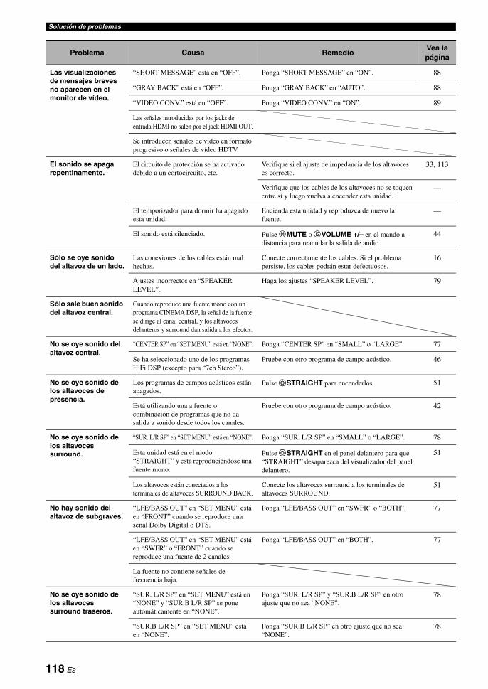
Solución de problemas
Las visualizaciones de mensajes breves no aparecen en el monitor de vídeo.
“SHORT MESSAGE” está en “OFF”. Ponga “SHORT MESSAGE” en “ON”. 88
“GRAY BACK” está en “OFF”. Ponga “GRAY BACK” en “AUTO”. 88
“VIDEO CONV.” está en “OFF”. Ponga “VIDEO CONV.” en “ON”. 89
Las señales introducidas por los jacks de entrada HDMI no salen por el jack HDMI OUT.
Se introducen señales de vídeo en formato progresivo o señales de vídeo HDTV.
El sonido se apaga repentinamente.
El circuito de protección se ha activado debido a un cortocircuito, etc.
Verifique si el ajuste de impedancia de los altavoces es correcto.
33, 113
Verifique que los cables de los altavoces no se toquen entre sí y luego vuelva a encender esta unidad.
—
El temporizador para dormir ha apagado esta unidad.
Encienda esta unidad y reproduzca de nuevo la fuente.
—
El sonido está silenciado. Pulse DMUTE o BVOLUME +/– en el mando a distancia para reanudar la salida de audio.
44
Sólo se oye sonido del altavoz de un lado.
Las conexiones de los cables están mal hechas.
Conecte correctamente los cables. Si el problema persiste, los cables podrán estar defectuosos.
16
Ajustes incorrectos en “SPEAKER LEVEL”.
Haga los ajustes “SPEAKER LEVEL”. 79
Sólo sale buen sonido del altavoz central.
Cuando reproduce una fuente mono con un programa CINEMA DSP, la señal de la fuente se dirige al canal central, y los altavoces delanteros y surround dan salida a los efectos.
No se oye sonido del altavoz central.
“CENTER SP” en “SET MENU” está en “NONE”. Ponga “CENTER SP” en “SMALL” o “LARGE”. 77
Se ha seleccionado uno de los programas HiFi DSP (excepto para “7ch Stereo”).
Pruebe con otro programa de campo acústico. 46
No se oye sonido de los altavoces de presencia.
Los programas de campos acústicos están apagados.
Pulse OSTRAIGHT para encenderlos. 51
Está utilizando una a fuente o combinación de programas que no da salida a sonido desde todos los canales.
Pruebe con otro programa de campo acústico. 42
No se oye sonido de los altavoces surround.
“SUR. L/R SP” en “SET MENU” está en “NONE”. Ponga “SUR. L/R SP” en “SMALL” o “LARGE”. 78
Esta unidad está en el modo “STRAIGHT” y está reproduciéndose una fuente mono.
Pulse OSTRAIGHT en el panel delantero para que “STRAIGHT” desaparezca del visualizador del panel delantero.
51
Los altavoces están conectados a los terminales de altavoces SURROUND BACK.
Conecte los altavoces surround a los terminales de altavoces SURROUND.
51
No hay sonido del altavoz de subgraves.
“LFE/BASS OUT” en “SET MENU” está en “FRONT” cuando se reproduce una señal Dolby Digital o DTS.
Ponga “LFE/BASS OUT” en “SWFR” o “BOTH”. 77
“LFE/BASS OUT” en “SET MENU” está en “SWFR” o “FRONT” cuando se reproduce una fuente de 2 canales.
Ponga “LFE/BASS OUT” en “BOTH”. 77
La fuente no contiene señales de frecuencia baja.
No se oye sonido de los altavoces surround traseros.
“SUR. L/R SP” en “SET MENU” está en “NONE” y “SUR.B L/R SP” se pone automáticamente en “NONE”.
Ponga “SUR. L/R SP” y “SUR.B L/R SP” en otro ajuste que no sea “NONE”.
78
“SUR.B L/R SP” en “SET MENU” está en “NONE”.
Ponga “SUR.B L/R SP” en otro ajuste que no sea “NONE”.
78
Problema Causa RemedioVea la página
118 Es

Solución de problemasIN
FO
RM
AC
IÓN
A
DIC
ION
AL
Esp
año
l
Las fuentes de entrada de audio no se pueden reproducir en el formato de señal de audio digital deseado. (El indicador de la fuente de entrada deseada o el indicador del decodificador en el visualizador del panel delantero no se encienden.)
El componente conectado no está ajustado para dar salida a las señales de audio digital deseadas.
Haga el ajuste apropiado siguiendo las instrucciones de su componente.
—
La selección de jack de entrada de audio está en “ANALOG”.
Ponga la selección de jack de entrada de audio en “AUTO”.
43
Se oye un sonido de zumbido.
Las conexiones de los cables están mal hechas.
Conecte firmemente los cables de audio. Si el problema persiste, los cables podrán estar defectuosos.
—
El giradiscos no está conectado al terminal GND.
Conecte el cable de tierra del giradiscos al terminal GND de esta unidad.
28
El nivel del sonido está bajo mientras se reproduce un disco.
El disco se reproduce en un giradiscos con cápsula MC.
Conecte su giradiscos a esta unidad mediante un amplificador para cabezal MC.
28
El nivel del sonido no se puede aumentar o el sonido está distorsionado.
El componente conectado a los jacks AUDIO OUT (REC) de esta unidad está apagado.
Conecte la alimentación del componente. —
El efecto de sonidos no se puede grabar.
No es posible grabar el efecto de sonidos con un componente de grabación.
No se puede grabar una fuente mediante un componente de grabación digital conectado al jack DIGITAL OUTPUT.
El componente fuente no está conectado a los jacks DIGITAL INPUT de esta unidad.
Conecte el componente fuente a los jacks DIGITAL INPUT.
25, 28
Algunos componentes no pueden grabar las fuentes Dolby Digital o DTS.
No se puede grabar una fuente mediante un componente analógico conectado a los jacks AUDIO OUT (REC).
El componente fuente no está conectado a los jacks AUDIO IN analógicos de esta unidad.
Conecte el componente fuente a los jacks AUDIO IN analógicos.
28
Los parámetros de campos acústicos y algunos otros ajustes de esta unidad no se pueden cambiar.
“MEMORY GUARD” en “SET MENU” está en “ON”.
Ponga “MEMORY GUARD” en “OFF”. 90
Esta unidad no funciona correctamente.
El microprocesador interno ha sido dañado por una descarga eléctrica externa (rayo o electricidad estática excesiva) o por una alimentación de baja tensión.
Desconecte el cable de alimentación de la toma de CA y luego vuelva a conectarlo después de 30 segundos.
—
“CHECK SP WIRES” aparece en el visualizador del panel delantero.
Los cables de los altavoces están cortocircuitados.
Asegúrese de que todos los cables de los altavoces están conectados correctamente.
16
Hay interferencia de ruido procedente de un equipo digital o de radiofrecuencia.
Esta unidad está demasiado cerca de un equipo digital o de alta frecuencia.
Separe más esta unidad de ese equipo. —
La imagen está distorsionada.
La fuente de vídeo utiliza señales cifradas y codificadas para evitar copiarlas.
Esta unidad entra repentinamente en el modo de espera.
La temperatura interna aumenta demasiado y se activa el circuito protector contra recalentamiento.
Espere 1 hora aproximadamente a que se enfríe la unidad y vuelva a encenderla.
—
Problema Causa RemedioVea la página
119 Es

Solución de problemas
Sintonizador
HDMI
Problema Causa RemedioVea la página
FM
La recepción estéreo por FM tiene ruido.
Las características de las emisiones estéreo de FM pueden causar este problema cuando el transmisor está muy lejos o la entrada de la antena es mala.
Verifique las conexiones de la antena. 32
Intente utilizar una antena de FM direccional de alta calidad.
—
Utilice el método de sintonización manual. 54
Hay distorsión y no se puede obtener una buena recepción a pesar de utilizar una buena antena de FM.
Hay interferencia de trayectorias múltiples.
Ajuste la posición de la antena para eliminar la interferencia de trayectorias multiples.
—
La emisora deseada no se puede sintonizar con el método de sintonización automática.
La señal es demasiado débil. Utilice una antena de FM direccional de alta calidad.
—
Utilice el método de sintonización manual. 54
Las emisoras presintonizadas previamente no se pueden volver a sintonizar.
La unidad ha estado desconectada durante mucho tiempo.
Presintonice de nuevo las emisoras. 55
AM
La emisora deseada no se puede sintonizar con el método de sintonización automática.
La señal es débil o las conexiones de la antena están flojas.
Apriete las conexiones de la antena de cuadro de AM y oriéntela para obtener la mejor recepción.
32
Utilice el método de sintonización manual. 54
Se oye ruido continuo de fritura y crepitación.
La antena de cuadro de AM suministrada no está conectada.
Conecte correctamente la antena de cuadro de AM aunque utilice una antena exterior.
32
El ruido se puede producir debido a los rayos, lámparas fluorescentes, motores, termostatos y otros equipos eléctricos.
Utilice una antena exterior y un cable de tierra. Esto ayudará algo, pero será difícil eliminar todo el ruido.
32
Hay ruido de zumbido y aullido.
Se está utilizando cerca un aparato de TV.
Separe esta unidad del TV. —
HDMI ERROR Causa RemedioVea la página
DEVICE OVER El número de componentes HDMI conectados sobrepasa el límite.
Reduzca el número de componentes HDMI conectados.
—
HDCP ERROR Ha fallado la autentificación HDCP. Compruebe que el componente HDMI conectado soporte las normas de protección contra la copia HDCP.
—
HDMI MESSAGE Causa RemedioVea la página
Out of Resolution
El monitor de vídeo conectado no es compatible con la resolución de la señal de vídeo de entrada.
Ajuste correctamente la resolución de la señal de salida de vídeo del componente fuente de entrada.
—
120 Es

Solución de problemasIN
FO
RM
AC
IÓN
A
DIC
ION
AL
Esp
año
l
Mando a distancia
Problema Causa RemedioVea la página
El mando a distancia no funciona o funciona mal.
Distancia o ángulo equivocados. El mando a distancia funcionará dentro de una distancia de 6 m y sin exceder un ángulo de 30 grados a partir del eje central del panel delantero.
36
La luz solar directa o de otras luces (lámpara fluorescente tipo inversor, etc.) cae directamente sobre el sensor de mando a distancia de esta unidad.
Cambie la posición de esta unidad. —
Las pilas están casi agotadas. Cambie todas las pilas. 5
El selector del modo de operación está mal puesto.
Ponga correctamente el selector del modo de operación. Cuando utilice esta unidad, póngalo en la posición CAMP. Cuando utilice el componente seleccionado por el botón selector de entrada, póngalo en la posición CSOURCE. Cuando utilice el TV en el área DTV o PHONO, póngalo en la posición CTV.
—
El código de mando a distancia no está ajustado correctamente.
Ponga correctamente el código del mando a distancia utilizando la “Lista de códigos de mando a distancia” al final de este manual.
99
Intente poner otro código del mismo fabricante usando “Lista de códigos de mando a distancia” al final de este manual.
99
El código de librería del mando a distancia y la identificación de mando a distancia de esta unidad no concuerdan.
Haga concordar la identificación de mando a distancia de esta unidad con el código de librería de mando a distancia correspondiente.
100, 114
Aunque el código del mando a distancia esté bien puesto, hay algunos modelos que no responderán al mando a distancia.
Programe independientemente las funciones necesarias en los botones programables utilizando la función de aprendizaje.
101
El mando a distancia no aprende funciones nuevas.
Las pilas de este mando a distancia y/o las del otro mando a distancia están agotadas.
Cambie las pilas. 5
La distancia entre los dos mandos a distancia es demasiado grande o pequeña.
Coloque los mandos a distancia a la distancia apropiada.
101
La modulación o codificación de señal del otro mando a distancia no es compatible con este mando a distancia.
No es posible aprender. —
La memoria está llena. Borre otras funciones que no necesite para dejar espacio para las funciones nuevas.
106
121 Es

Solución de problemas
iPod
En el caso de producirse un error de transmisión sin que aparezca un mensaje de estado en el panel delantero ni en la OSD, compruebe la conexión de su iPod (vea la página 31).
AUTO SETUP
Antes de AUTO SETUP
Nota
Mensaje de estado Causa RemedioVea la página
Loading... Esta unidad está reconociendo la conexión con su iPod.
Esta unidad está adquiriendo la lista de canciones de su iPod.
Connect error Hay un problema con la trayectoria de señal de su iPod a esta unidad.
Apague esta unidad y vuelva a conectar el acoplador universal Yamaha iPod al terminal DOCK de esta unidad.
31
Intente reponer su iPod. —
Unknown type El iPod que está siendo usado no es compatible con esta unidad.
Sólo son compatibles los iPod (Click and Wheel), iPod nano y iPod mini.
—
iPod connected Su iPod está bien acoplado a un acoplador universal Yamaha iPod (como el YDS-10, vendido separadamente) conectado al terminal DOCK de esta unidad, y la conexión entre su iPod y esta unidad está terminada.
Disconnected Su iPod fue desacoplado de un acoplador universal Yamaha iPod (como el YDS-10, vendido separadamente) conectado al terminal DOCK de esta unidad.
Acople su iPod en un acoplador universal Yamaha iPod (como el YDS-10 opcional) conectado al terminal DOCK de esta unidad.
31
Unable to play Esta unidad puede reproducir las canciones actualmente guardadas en su iPod.
Compruebe que las canciones actualmente guardadas en su iPod puedan reproducirse.
—
Guarde en su iPod algunas otras canciones que puedan reproducirse.
—
Mensaje de error Causa RemedioVea la página
Connect MIC! El micrófono optimizador no está conectado.
Conecte el micrófono optimizador suministrado al jack OPTIMIZER MIC del panel delantero.
37
Unplug HP! Hay auriculares conectados. Desconéctelos. —
122 Es

Solución de problemasIN
FO
RM
AC
IÓN
A
DIC
ION
AL
Esp
año
l
Durante AUTO SETUP
Después de AUTO SETUP
• Si aparece la pantalla “ERROR” o “WARNING”, compruebe la causa del problema, y luego realice de nuevo el procedimiento “AUTO SETUP”.
• Si aparece el mensaje de advertencia “W-2” o “W-3” se hacen los ajustes, sin embargo, puede que éstos no sean óptimos.• Dependiendo de los altavoces, el mensaje de advertencia “W-1” puede aparecer aunque las conexiones de los altavoces estén bien hechas.• Si aparece repetidamente un mensaje de error “E-10”, póngase en contacto con un centro de servicio Yamaha cualificado.
Mensaje de error Causa RemedioVea la página
E-1:NO FRONT SP No se detectan señales de los canales delanteros Izquierdo/Derecho.
Compruebe las conexiones de los altavoces delanteros Izquierdo/Derecho.
16
E-2:NO SUR.SP No se detecta una señal de canal surround. Compruebe las conexiones del altavoz surround.
16
E-3:NO PRNS SP No se detecta una señal de canal de presencia.
Compruebe las conexiones del altavoz de presencia.
16
E-4:SBR.SBL Sólo se detecta la señal del canal surround trasero derecho.
Conecte el altavoz surround trasero al terminal de altavoz SURROUND BACK (SINGLE) si sólo tiene un altavoz surround trasero.
16
E-5:NOISY El ruido de fondo está muy alto. Intente hacer “AUTO SETUP” en un ambiente silencioso.
—
Apague el equipo eléctrico ruidoso, como acondicionadores de aire, o sepárelo del micrófono optimizador.
—
E-6:CHECK SUR. Los altavoces surround traseros están conectados, pero los altavoces surround Izquierdo/Derecho no lo están.
Conecte los altavoces surround cuando utilice altavoces surround traseros.
17
E-7:NO MIC El micrófono optimizador fue desenchufado durante el procedimiento “AUTO SETUP”.
Conecte el micrófono optimizador suministrado al jack OPTIMIZER MIC del panel delantero.
37
E-8:NO SIGNAL El micrófono optimizador no detecta tonos de prueba.
Compruebe el ajuste del micrófono. 37
Compruebe las conexiones y la instalación de los altavoces.
16
E-9:USER CANCEL El procedimiento “AUTO SETUP” fue cancelado debido a actividades del usuario.
Haga de nuevo “AUTO SETUP”. 37
E-10:INTERNAL ERROR Se ha producido un error interno. Haga de nuevo “AUTO SETUP”. 37
Mensaje de advertencia Causa RemedioVea la página
W-1:OUT OF PHASE La polaridad de los altavoces no es la correcta. Este mensaje puede aparecer dependiendo de los altavoces aunque estos estén conectados correctamente.
Compruebe los altavoces para ver si las conexiones de polaridad son correctas (+ o –).
16
W-2:OVER 24m (80ft) La distancia entre el altavoz y la posición de escucha es superior a 24 m.
Acerque el altavoz a la posición de escucha. —
W-3:LEVEL ERROR La diferencia en el nivel del sonido entre los altavoces es excesiva.
Reajuste la instalación de los atavoces para que todos ellos estén en lugares con condiciones similares.
—
Verifique las conexiones de los altavoces. 16
Utilice altavoces de calidad similar. —
Ajustan el volumen de salida del altavoz de subgraves.
37
Notas
123 Es

REPOSICIÓN DEL SISTEMA
Use esta función para reponer todos los parámetros de esta unidad a los ajustes iniciales de fábrica.
• Este procedimiento repone completamente todos los parámetros de esta unidad, incluyendo los parámetros “SET MENU”. Sin embargo, los parámetros del menú de ajuste avanzado no se inicializarán.
• Los ajustes de fábrica iniciales se activan la próxima vez que usted enciende esta unidad.
yPara cancelar el procedimiento de inicialización en cualquier momento sin hacer ningún cambio, pulse AMASTER ON/OFF en el panel delantero para soltarlo hacia afuera hacia la posición OFF.
1 Pulse AMASTER ON/OFF en el panel delantero para soltarlo hasta la posición OFF y apagar esta unidad.
2 Mantenga pulsado OSTRAIGHT y luego pulse AMASTER ON/OFF hasta la posición ON para encender esta unidad.Esta unidad se enciende y “ADVANCED SETUP” aparece en el visualizador del panel delantero.
3 Gire el selector NPROGRAM para seleccionar “INITIALIZE”.
4 Pulse repetidamente OSTRAIGHT para seleccionar “ALL”.
y• Seleccione “CANCEL” para cancelar el procedimiento de
inicialización sin hacer ningún cambio.• Puede inicializar separadamente los parámetros de vídeo y
los parámetros de programas de campos acústicos. Vea la página 116 para conocer detalles.
5 Pulse AMASTER ON/OFF para soltarlo hasta la posición OFF y confirmar su elección y apague esta unidad.
Reposición del sistema
Notas
EFFECT
STRAIGHT
MASTER
Mientras lo mantiene pulsado
I N I T I A L I Z E
C A N C E L
I N I T I A L I Z E
A L L
124 Es

GLOSARIOIN
FO
RM
AC
IÓN
A
DIC
ION
AL
Esp
año
l
Sincronización de audio y vídeo (sincronización de voz)
La sincronización de voz es un término técnico que se refiere al mismo tiempo a un problema y a una capacidad de mantener las señales de audio y vídeo sincronizadas durante la postproducción y la transmisión. Mientras que el estado latente de audio y vídeo requiere que el usuario final realice ajustes complejos, la versión 1.3 de HDMI incorpora una capacidad de sincronización automática de audio y vídeo que permite que los aparatos realicen esta sincronización.
Conexión de biamplificaciónLa conexión biamplificación usa dos amplificadores para un altavoz. Un amplificador se conecta a la sección del altavoz de graves y el otro se conecta a la sección de altavoz de gama central y altavoz de agudos combinados. Con esta disposición, cada amplificador funciona con una gama de frecuencias limitada. Esta gama limitada presenta a cada amplificador un trabajo más sencillo, siendo menos probable que cada amplificador influya en el sonido de alguna forma. El filtro separador interno del altavoz consiste en un LPF (filtro pasabajos) y un HPF (filtro pasaaltos). Como su nombre indica, el LPF da paso a las frecuencias inferiores a la frecuencia de corte y rechaza las frecuencias superiores a la frecuencia de corte. De forma similar, el HPF da paso a las frecuencias superiores a la frecuencia de corte.
Señal de vídeo componenteCon el sistema de señal de vídeo componente, la señal de vídeo se separa en señal Y para la luminancia y señales PB y PR para la crominancia. El color se puede reproducir más fielmente con este sistema porque cada una de estas señales es independiente. La señal componente también se llama “señal de diferencia de color” porque la señal de luminancia se quita de la señal de color. Para dar salida a las señales de vídeo componente se necesita un monitor con jacks de entrada de vídeo componente.
Señal de vídeo compuestoCon el sistema de señal de vídeo compuesto, la señal de vídeo se compone de tres elementos básicos de imagen de vídeo: color, brillo y datos de sincronización. Un jack de vídeo compuesto en un componente de vídeo trasmite estos tres elementos combinados.
Deep ColorDeep Color se refiere al uso de varias profundidades de colores en las pantallas; profundidades de hasta 24 bits en las versiones previas de la especificación HDMI. Esta profundidad de bits extra permite a los HDTV y a otras pantallas pasar de mostrar millones de colores a mostrar miles de millones de colores, y eliminar el franjeado cromático en las pantallas para efectuar transiciones tonales suaves y sutiles gradaciones entre los colores. La relación de contraste aumentada puede representar muchos más matices del gris entre el negro y el blanco. Además, Deep Color aumenta el número de colores disponibles dentro de los límites definidos por el espacio cromático de RGB o YCbCr.
Normalización de diálogoLa normalización del diálogo es una función de Dolby Digital o DTS que se utiliza para mantener los programas con el mismo nivel de escucha medio, para que los usuarios no tengan que cambiar el volumen de los programas Dolby Digital o DTS.
Dolby DigitalDolby Digital es un sistema de sonido surround digital que le proporciona un sonido de múltiples canales completamente independiente. Con 3 canales delanteros (izquierdo, derecho y central) y 2 canales surround estéreo, Dolby Digital proporciona 5 canales de audio de gama completa. Con un canal adicional especial para efectos graves, llamado LFE (efecto de baja frecuencia), el sistema tiene un total de 5.1 canales (LFE se cuenta como canal 0.1). Utilizando estéreo de 2 canales para los altavoces surround, es posible obtener efectos de sonido en movimiento y ambientes de sonido surround más precisos que con Dolby Surround. La amplia gama dinámica (desde el volumen máximo al mínimo) reproducida por los 5 canales de gama completa y la orientación precisa del sonido generada mediante procesamiento de sonido digital proporcionan al oyente una sensación y realismo nunca antes logrados. Con esta unidad, cualquier ambiente de sonido desde mono hasta la configuración de 5.1 canales se puede seleccionar libremente para disfrutar de él.
Dolby Digital EXDolby Digital EX crea 6 canales de salida de banda ancha de fuentes de 5.1 canales. Esto se logra utilizando un decodificador de matriz que saca 3 canales surround de los 2 de la grabación original. Para obtener los mejores resultados, Dolby Digital EX deberá utilizarse con pistas de sonido de películas grabadas con Dolby Digital Surround EX. Con este canal adicional, usted podrá experimentar sonido en movimiento más dinámico y real, especialmente con escenas de efectos de “desfiles aéreos” y “vuelos rasantes”.
Glosario
125 Es
Glosario
Dolby Digital PlusDolby Digital Plus es una tecnología de audio avanzada desarrollada para la programación de alta definición y para los medios entre los que se incluyen las emisiones HD, HD DVD y Blu-ray Disc. Seleccionada como norma de audio obligatoria para HD DVD y como norma de audio opcional para Blu-ray Disc, esta tecnología proporciona un sonido multicanal con salida de canales discretos. Soportando velocidades de bits de hasta 6,0 Mbps, Dolby Digital Plus puede transportar simultáneamente hasta 7.1 canales de audio discretos. Soportado por la versión 1.3 de HDMI y diseñado para los reproductores de discos ópticos y los receptores/amplificadores de AV del futuro, Dolby Digital Plus sigue siendo totalmente compatible con los sistemas de audio multicanal existentes que incorporan Dolby Digital.
Dolby Pro Logic IIDolby Pro Logic II es una técnica mejorada utilizada para decodificador grandes cantidades de fuentes Dolby Surround existentes. Esta nueva tecnología permite realizar una reproducción discreta de 5 canales con 2 canales delanteros derecho e izquierdo, 1 canal central y 2 canales surround derecho e izquierdo en lugar de 1 solo canal surround para la tecnología Pro Logic convencional. Hay tres modos disponibles: “Modo Music” para fuentes de música, “modo Movie” para fuentes de películas y “modo Game” para fuentes de juegos.
Dolby Pro Logic IIxDolby Pro Logic IIx es una tecnología nueva que permite realizar una reproducción discreta de fuentes de 2 canales o de múltiples canales. Hay tres modos disponibles: “Modo Music” para fuentes de música, “Mode Movie” para fuentes de películas (para fuentes de 2 canales solamente) y “Mode Game” para fuentes de juegos.
Dolby SurroundDolby Surround utiliza un sistema de grabación analógica de 4 canales para reproducir efectos de sonido reales y dinámicos: 2 canales delanteros derecho e izquierdo (estéreo), un canal central para el diálogo (mono) y un canal surround para efectos especiales (mono). El canal surround reproduce sonido dentro de una gama de frecuencias estrecha. Dolby Surround se utiliza ampliamente con casi todas las cintas de vídeo y discos láser, y también en muchas emisiones de TV y TV por cable. El decodificador Dolby Pro Logic incorporado en esta unidad emplea un sistema de procesamiento digital de señales que estabiliza automáticamente el volumen de cada canal para realzar los efectos y direccionalidad del sonido.
Dolby TrueHDDolby TrueHD es una tecnología de audio sin pérdida avanzada desarrollada para los medios basados en discos y de alta definición que incluyen HD DVD y Blu-ray Disc. Seleccionada como norma de audio obligatoria para HD DVD y como norma de audio opcional para Blu-ray Disc, esta tecnología proporciona un sonido que es bit a bit idéntico al original, ofreciendo una experiencia de cine en casa de alta definición. Soportando velocidades de bits de hasta 18,0 Mbps, Dolby TrueHD puede transportar simultáneamente hasta 8 canales discretos de audio de 24 bits/96 kHz. Soportado por la versión 1.3 de HDMI y diseñado para los reproductores de discos ópticos y los receptores/amplificadores de AV del futuro, Dolby TrueHD sigue siendo totalmente compatible con los sistemas de audio multicanal existentes y retiene la capacidad de metadatos de Dolby Digital, permitiendo la normalización de los diálogos y el control de la gama dinámica.
DSDLa tecnología Direct Stream Digital (DSD) guarda señales de audio en medios de almacenamiento digital, como los Super Audio CDs. Usando DSD, las señales se guardan como valores de un solo bit a frecuencias de muestreo altas de 2,8224 MHz, mientras que la formación de ruido y el sobremuestreo se utilizan para reducir la distorsión, algo muy común con la cuantificación muy alta de las señales de audio. Gracias a la frecuencia de muestreo alta se puede lograr una sonido de mejor calidad que el ofrecido por el formato PCM de los CDs de audio normales.
DTS 96/24DTS 96/24 ofrece un nivel sin precedentes de calidad de audio para el sonido de múltiples canales en vídeo DVD, y es compatible con todos los decodificadores DTS. “96” se refiere a una frecuencia de muestreo de 96 kHz comparada con la típica frecuencia de muestreo de 48 kHz. “24” se refiere a una longitud de palabra de 24 bits. DTS 96/24 ofrece una calidad de sonido transparente al valor maestro 96/24 original, y un sonido de 5.1 canales de 96/24 con vídeo de pleno movimiento y máxima calidad para los programas de música y las pistas de sonido de películas de vídeo DVD.
126 Es
GlosarioIN
FO
RM
AC
IÓN
A
DIC
ION
AL
Esp
año
l
DTS Digital SurroundDTS digital surround fue desarrollado para reemplazar las pistas de sonido analógico de las peliculas por pistas de sonido digital de 6.1 canales, y actualmente está ganando una gran popularidad en los cines de todo el mundo. DTS, Inc. ha desarrollado una sistema de cine para casa con el que usted puede disfrutar de la profundidad del sonido y la representación espacial natural de surround digital DTS en su propia casa. Este sistema produce un sonido de 6 canales prácticamente sin distorsión (técnicamente los canales delanteros derecho e izquierdo, central, surround izquierdo y derecho, más 0.1 LFE (subgraves), para un total de 5.1 canales). Esta unidad incorpora un decodificador DTS-ES que permite reproducir 6.1 canales agregando el canal surround trasero al formato de 5.1 canales existente.
DTS ExpressDTS Express es una tecnología de audio avanzada para las funciones opcionales de Blu-ray Disc o HD DVD que ofrece alta calidad, audio de baja velocidad de bits optimizado para usar en redes, y aplicaciones de Internet. DTS Express se usa para la función de audio secundario de Blu-ray Disc o para la función de subaudio de HD DVD. Estas funciones proporcionan comentarios de audio (por ejemplo, los comentarios adicionales hechos por el director de una película) al pedirlos los usuarios mediante Internet, etc. Las señales DTS Express se mezclan con el audio principal del componente de reproducción, y el componente envía audio mezclado a los receptores/amplificadores de AV mediante conexiones coaxiales digitales, ópticas digitales o analógicas.
DTS-HD High Resolution AudioDTS-HD High Resolution Audio es una tecnología de audio de alta resolución desarrollada para los medios basados en discos y de alta definición que incluyen HD DVD y Blu-ray Disc. Seleccionada como norma de audio opcional para HD DVD y Blu-ray Disc, esta tecnología proporciona un sonido que es virtualmente idéntico al original, ofreciendo una experiencia de cine en casa de alta definición. Soportando velocidades de bits de hasta 3,0 Mbps para HD DVD y 6,0 Mbps para Blu-ray Disc, DTS-HD High Resolution Audio puede transportar simultáneamente hasta 7.1 canales discretos de audio de 24 bits/96 kHz.. Soportado por la versión 1.3 de HDMI y diseñado para los reproductores de discos ópticos y los receptores/amplificadores de AV del futuro, DTS-HD High Resolution Audio sigue siendo totalmente compatible con los sistemas de audio multicanal existentes que incorporan DTS Digital Surround.
DTS-HD Master AudioDTS-HD Master Audio es una tecnología de audio sin pérdida avanzada desarrollada para los medios basados en discos y de alta definición que incluyen HD DVD y Blu-ray Disc. Seleccionada como norma de audio obligatoria para HD DVD y Blu-ray Disc, esta tecnología proporciona un sonido que es bit a bit idéntico al original, ofreciendo una experiencia de cine en casa de alta definición. Soportando velocidades de bits de hasta 18,0 Mbps para HD DVD y de hasta 24,5 Mbps para Blu-ray Disc, DTS-HD Master Audio puede transportar simultáneamente hasta 7.1 canales discretos de audio de 24 bits/96 kHz. Soportado por la versión 1.3 de HDMI y diseñado para los reproductores de discos ópticos y los receptores de AV del futuro, DTS-HD Master Audio sigue siendo totalmente compatible con los sistemas de audio multicanal existentes que incorporan DTS Digital Surround.
HDMIHDMI (Interfaz multimedia de alta definición) es la primera interfaz de audio/vídeo completamente digital y sin compresión que está soportada por la industria. Proporcionando una interfaz entre cualquier fuente (receptor digital multimedia o receptor A/V) y un monitor de audio/vídeo (televisor digital), HDMI soporta vídeo estándar, realzado o de alta definición, así como también audio digital multicanal usando un solo cable. HDMI transmite todas las normas de ATSC HDTV, y soporta el audio digital de 8 canales, con ancho de banda de sobra para acomodar futuras mejoras y requerimientos.Cuando se usa en combinación con HDCP (protección de contenido digital de ancho de banda alto), HDMI proporciona una interfaz de audio/vídeo segura que cumple con los requisitos de seguridad de los proveedores de contenido y operadores de sistemas. Para tener más información de HDMI, visite el sitio Web de HDMI en “http://www.hdmi.org/”.
Canal 0.1 LFEEste canal reproduce señales de baja frecuencia. La gama de frecuencias de este canal es de 20 Hz a 120 Hz. Este canal se cuenta como 0.1 porque sólo impone una gama de frecuencias bajas en comparación con la gama completa reproducida por los otros 5/6 canales de los sistemas Dolby Digital o DTS de 5.1/6.1 canales.
Neo:6Neo:6 decodifica las fuentes de 2 canales convencionales para reproducir 6 canales empleando un decodificador específico. Permite reproducir los canales de gama completa con una separación mas alta, como en la reproducción de señal discreta digital. Hay tres modos disponibles: “Mode Music” para fuentes de música y “Mode Cinema” para fuentes de películas.
127 Es

Glosario
PCM (Lineal PCM)Lineal PCM es un formato de señal bajo el cual una señal de audio analógico se digitaliza, se graba y se transmite sin utilizar ninguna compresión. Esto se utiliza como un método de grabación de CDs y DVD audio. El sistema PCM utiliza una técnica para muestrear el tamaño de la señal analógica por unidades de tiempo muy pequeñas. Significando “modulación por codificación de impulsos”, la señal analógica se codifica como impulsos y luego se modula para la grabación.
Frecuencia de muestreo y número de bits cuantificados
Cuando se digitaliza una señal de audio analógico, el número de veces que se muestrea la señal por segundo recibe el nombre de frecuencia de muestreo, mientras que el grado de idoneidad cuando el nivel del sonido se convierte en valor numérico se llama bits cuantificados. La gama de frecuencias que se puede reproducir se determina mediante la frecuencia de muestreo, mientras que la gama dinámica que representa la diferencia del nivel del sonido se determina mediante el número de bits cuantificados. En principio, cuanto más alta es la frecuencia de muestreo, más amplia es la gama de frecuencias que puede reproducirse, y cuanto más alto es el número de bits cuantificados, más preciso es el nivel del sonido que puede reproducirse.
Señal S-vídeoCon el sistema de señal S-vídeo, la señal de vídeo transmitida normalmente utilizando un cable con clavija se separa y transmite como señal Y para la luminancia y señal C para la crominancia a través del cable de S-vídeo. Utilizando el jack S VIDEO se elimina la pérdida de transmisión de la señal de vídeo y se pueden grabar y reproducir imágenes aún más hermosas.
128 Es

INFORMACIÓN DE PROGRAMAS DE CAMPOS ACÚSTICOSIN
FO
RM
AC
IÓN
A
DIC
ION
AL
Esp
año
l
Elementos de un campo acústicoLo que realmente crea los tonos ricos y completos de un instrumento son los múltiples reflejos de las paredes de la habitación. Además de dar vida al sonido, estos reflejos nos permiten saber dónde están situados los músicos, y también el tamaño y la forma de la habitación en la que estamos sentados.Además del sonido directo que viene directo a nuestros oídos desde el instrumento del intérprete hay dos tipos distintos de reflejos del sonido que se combinan para formar el campo acústico.
Primeros reflejosLos sonidos reflejados llegan muy rápidamente a nuestros oídos (50 ms a 100 ms después del sonido directo) tras reflejarse en una superficie solamente como, por ejemplo, una pared o el techo. Los primeros reflejos, en realidad, agregan claridad al sonido directo.
ReverberacionesÉstas se deben a los reflejos de más de una superficie (por ejemplo, las paredes y/o el techo), tan numerosos que se juntan para formar una ráfaga sónica continua. No son direccionales y reducen la claridad del sonido directo.
El sonido directo, los primeros reflejos y las reverberaciones posteriores se unen para determinar el tamaño y la forma subjetivos de la habitación, y es esta información la que el procesador del campo acústico digital reproduce para crear campos acústicos.
Si pudiera crear los primeros reflejos y reverberaciones posteriores apropiados en su sala de escucha, sería capaz de crear su propio ambiente de escucha. La acústica de su habitación puede cambiar y pasar a ser la de una sala de conciertos, una sala de baile o una habitación de cualquier tamaño. Esta habilidad para crear campos de sonido a voluntad es exactamente lo que Yamaha ha hecho con el procesador de campo acústico digital.
CINEMA DSPComo los sistemas Dolby Surround y DTS fueron diseñados originalmente para ser utilizados en cines, su efectos se notan mejor en un cine con muchos altavoces diseñados para efectos acústicos. Como las condiciones de una casa, tales como el tamaño de la habitación, el material de las paredes, el número de altavoces, etc., pueden cambiar tanto, es inevitable que se produzcan también diferencias en el sonido. Tomando como base la abundancia de datos medidos realmente, Yamaha CINEMA DSP proporciona la experiencia audiovisual de un cine en la habitación donde usted escucha en su propia casa utilizando la tecnología de campo acústico original de Yamaha combinada con varios sistemas de audio digital.
SILENT CINEMAYamaha ha desarrollado un algoritmo DSP de efectos de sonido reales para los auriculares. Los parámetros para los auriculares han sido establecidos para cada campo acústico de forma que se pueda disfrutar con auriculares de representaciones precisas de todos los programas de campos acústicos.
Virtual CINEMA DSPYamaha ha desarrollado un algoritmo Virtual CINEMA DSP que le permite disfrutar, utilizando altavoces surround virtuales, de los efectos surround de los campos acústicos DSP saunque no disponga de altavoces surround. Hasta se puede disfrutar de Virtual CINEMA DSP utilizando un sistema con un mínimo de dos altavoces sin altavoz central.
Compressed Music EnhancerLa característica Compressed Music Enhancer de esta unidad mejora su experiencia al escuchar regenerando las armónicas que faltan en un artefecto de compresión. Por consiguiente, se compensa la complejidad aplanada debida a la pérdida de fidelidad de las frecuencias altas y la falta de graves debida a la pérdida de graves de bajas frecuencias, proporcionando un rendimiento mejorado de todo el sistema de sonido.
No hay salida de sonido de cada altavozLa salida de sonido de cada altavoz depende del tipo de las señales de audio que están siendo introducidas. Consulte los diagramas de la tabla de abajo para entender la disposición de altavoces para cada programa de campo acústico. Para conocer detalles de la salida de sonido de cada altavoz en los programas de campo acústico, consulte “Salida de sonido en cada programa de campo acústico” en “APPENDIX” al final de este manual.
Tenga en cuenta que tal vez no haya salida de sonido, o ésta no sea suficiente, de los altavoces según el tipo de fuente de entrada que esté siendo reproducida. Además, puede haber algunos canales que sólo puedan usarse parcialmente cuando sean ajustados según aspectos específicos de las películas como, por ejemplo, efectos de sonido especiales, etc.
yExcepto para “2ch Stereo”, “7ch Stereo” y “STRAIGHT”, usted puede seleccionar un decodificador para dar salida al sonido de los altavoces surround traseros (vea la página 46).
Información de programas de campos acústicos
Nota
129 Es

INFORMACIÓN DE ECUALIZADOR PARAMÉTRICO
Esta unidad emplea la tecnología Yamaha Parametric Room Acoustic Optimizer (YPAO) para mejorar las características de frecuencias de su ecualizador paramétrico y adaptarlas a su ambiente de escucha. YPAO utiliza una combinación de los tres parámetros siguientes (frecuencia, ganancia y factor Q) para proporcionar un ajuste muy preciso de las características de frecuencias.
FrecuenciaEste parámetro se puede ajustar en incrementos de un tercio de octava, entre 32 Hz y 16 kHz.
GainEste parámetro se puede ajustar en incremetnos de 0,5 dB entre –20 y +6 dB.
Factor QAl ancho de la banda de frecuencias especificada se le llama factor Q. Este parámetro se puede ajustar entre los valores 0,5 y 10.
YPAO ajusta las características de frecuencias para adaptarlas a su ambiente de escucha, utilizando una combinación de los tres parámetros indicados anteriormente (frecuencia, ganancia y factor Q) para cada banda de ecualizador del ecualizador paramétrico de esta unidad. Esta unidad tiene 7 bandas de ecualizador para cada canal.El uso de múltiples bandas de ecualizador permite hacer ajustes más precisos de las características de frecuencias (como en la Figura 2). Esto no es posible utilizando solamente una sola banda de ecualizador (como en la Figura 1).
Figura 1
Figura 2
Información de ecualizador paramétrico
Gain
Frecuencia
Característica de frecuencia original
Banda 1
Característica de frecuencia tras la corrección
Gain
Frecuencia
Banda 1
Banda 2
Característica de frecuencia tras la corrección
Característica de frecuencia original
130 Es

ESPECIFICACIONESIN
FO
RM
AC
IÓN
A
DIC
ION
AL
Esp
año
l
SECCIÓN DE AUDIO• Potencia de salida RMS mínima para los altavoces delanteros,
central, surround y surround trasero20 Hz a 20 kHz, THD de 0,04%, 8 Ω.................................. 130 W
• Potencia dinámica (IHF)8/6/4/2 Ω ........................................................ 160/195/255/335 W
• Potencia de salida útil máxima (JEITA)[Modelos de Asia, General, China y Corea]
1 kHz, THD de 10%, 8 Ω ................................................... 175 W
• Potencia de salida máxima [Modelos del R.U. y Europa]1 kHz, THD de 0,7%, 4 Ω .................................................. 180 W
• Techo dinámico8 Ω ...................................................................................... 0,9 dB
• Potencia de salida IEC [Modelos del R.U. y Europa]1 kHz, THD de 0,04%, 8 Ω ................................................ 130 W
• Factor de amortiguación (IHF)20 Hz a 20 kHz, 8 Ω ..................................................... 150 o más
• Sensibilidad de entrada/Impedancia de entradaPHONO .................................................................. 3,5 mV/47 kΩCD, etc. ................................................................. 200 mV/47 kΩMULTI CH INPUT ............................................... 200 mV/47 kΩ
• Tensión de entrada máximaPHONO (1 kHz, 0,1% THD) ................................... 60 mV o másCD, etc. (1 kHz, 0,5% THD) ..................................... 2,4 V o más
• Tensión de salida nominal/Impedancia de salidaOUT (REC) ........................................................... 200 mV/900 ΩPRE OUT .................................................................. 1,0 V/1,2 kΩSUBWOOFER .......................................................... 2,0 V/1,2 kΩZONE 2/ZONE 3 OUT ............................................. 1,0 V/1,4 kΩ
• Salida/impedancia nominal del jack de auricularesCD, etc. (1 kHz, 40 mV, 8 Ω) ............................... 150 mV/100 Ω
• Respuesta de frecuenciaCD a delanteros L/R, Pure Direct ...... 10 Hz a 100 kHz, +0/–3 dB
• Desviación de ecualización RIAAPHONO (20 Hz a 20 kHz) ............................................ 0 ± 0,5 dB
• Distorsión armónica totalPHONO a OUT (REC)
(20 Hz a 20 kHz, 1 V) ........................................ 0,02% o menosCD, etc. a delanteros L/R
(20 Hz a 20 kHz, 65 W, 8 Ω) ............................ 0,04% o menos
• Relación señal a ruido (red IHF-A)PHONO (5 mV) a delanteros L/R[Modelos de Australia, R.U. y Europa] ..................... 81 dB o más[Otros modelos] ......................................................... 86 dB o másCD, etc. (250 mV) a delanteros L/R ........................ 100 dB o más
• Ruido residual (red IHF-A)Delanteros L/R .................................................... 150 µV o menos
• Separación de canales (1 kHz/10 kHz)PHONO (cortocircuitado) a delanteros L/R
...................................................................... 60 dB/55 dB o másCD, etc.(5,1 kΩ cortocircuitado)
a delanteros L/R ........................................... 60 dB/45 dB o más
• Control de tono (delanteros L/R, central, subgraves)Refuerzo/corte BASS ................................................ ±6 dB/50 HzFrecuencia de transisión BASS .......................................... 350 HzRefuerzo/corte TREBLE ......................................... ±6 dB/20 kHzFrecuencia de transisión TREBLE .....................................3,5 kHz
• Control de tono Zone 2/Zone 3 (delanteros L/R)Refuerzo/corte BASS ............................................ ±10 dB/100 HzFrecuencia de transisión BASS .......................................... 450 HzRefuerzo/corte TREBLE ....................................... ±10 dB/10 kHzFrecuencia de transisión TREBLE .....................................2,0 kHz
• Características de filtro (fc=40/60/80/90/100/110/120/160/200 Hz)H.P.F. (delanteros, central, surround, surround traseros)
..................................................................................... 12 dB/oct.L.P.F. (subgraves) .......................................................... 24 dB/oct.
SECCIÓN DE VÍDEO• Formato de vídeo (Fondo gris)
[Modelos de EE.UU., Canadá, General y Corea] ............... NTSC[Modelos del R.U., Europa, Australia, Asia y China] ............ PAL
• Formato de vídeo (Conversión de vídeo) ....................... NTSC/PAL
• Nivel de señalCompuesto ..................................................................1 Vp-p/75 ΩS-vídeo ............................ 1 Vp-p/75 Ω (Y), 0,286 Vp-p/75 Ω (C)Componente ................. 1 Vp-p/75 Ω (Y), 0,7 Vp-p/75 Ω (PB/PR)
• Nivel de entrada máximo (Conversión de vídeo desactivada)................................................................................... 1,5 Vp-p o más
• Relación señal a ruido (Conversión de vídeo desactivada)....................................................................................... 60 dB o más
• Respuesta de frecuencia (MONITOR OUT)Componente (Conversión de vídeo desactivada)
............................................................... 5 Hz a 100 MHz, ±3 dB
SECCIÓN DE FM• Gama de sintonización
[Modelos de EE.UU. y Canadá] ....................... 87,5 a 107,9 MHz[Modelos de Asia y General] ...... 87,5/87,50 a 108,0/108,00 MHz[Otros modelos] ............................................ 87,50 a 108,00 MHz
• Umbral de silenciamiento de 50 dB (IHF)Mono/estéreo ....................................... 2,0/25 µV (17,3/39,2 dBf)
• Sensibilidad útil (IHF) .......................................... 1,0 µV (11,2 dBf)
• Selectividad (400 kHz) ............................................................ 70 dB
• Relación señal a ruido (IHF)Mono/estéreo ............................................................. 76 dB/70 dB
• Distorsión armónica (1 kHz)Mono/estéreo ................................................................... 0,2/0,3%
• Separación estéreo (1 kHz)Estéreo .................................................................................. 42 dB
• Respuesta de frecuenciaEstéreo ............................................. 20 Hz a 15 kHz, +0,5, –2 dB
• Entrada de antena (desequilibrada) .......................................... 75 Ω
SECCIÓN DE AM• Gama de sintonización
[Modelos de EE.UU. y Canadá] ........................... 530 a 1710 kHz[Modelos de Asia y General] ............... 530/531 a 1710/1611 kHz[Otros modelos] .................................................... 531 a 1611 kHz
• Sensibilidad útil ................................................................ 300 µV/m
Especificaciones
131 Es
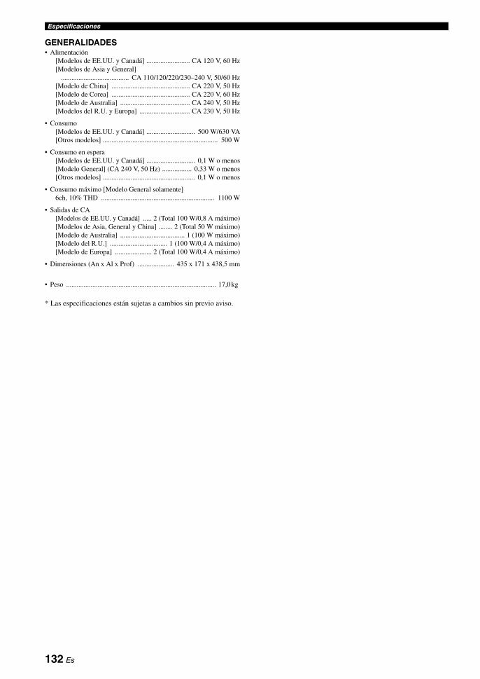
Especificaciones
GENERALIDADES• Alimentación
[Modelos de EE.UU. y Canadá] ......................... CA 120 V, 60 Hz[Modelos de Asia y General]
....................................... CA 110/120/220/230–240 V, 50/60 Hz[Modelo de China] ............................................. CA 220 V, 50 Hz[Modelo de Corea] ............................................. CA 220 V, 60 Hz[Modelo de Australia] ........................................ CA 240 V, 50 Hz[Modelos del R.U. y Europa] ............................. CA 230 V, 50 Hz
• Consumo[Modelos de EE.UU. y Canadá] ............................ 500 W/630 VA[Otros modelos] .................................................................. 500 W
• Consumo en espera[Modelos de EE.UU. y Canadá] ............................ 0,1 W o menos[Modelo General] (CA 240 V, 50 Hz) ................. 0,33 W o menos[Otros modelos] ..................................................... 0,1 W o menos
• Consumo máximo [Modelo General solamente]6ch, 10% THD ................................................................. 1100 W
• Salidas de CA[Modelos de EE.UU. y Canadá] ..... 2 (Total 100 W/0,8 A máximo)[Modelos de Asia, General y China] ........ 2 (Total 50 W máximo)[Modelo de Australia] ..................................... 1 (100 W máximo)[Modelo del R.U.] ................................. 1 (100 W/0,4 A máximo)[Modelo de Europa] ..................... 2 (Total 100 W/0,4 A máximo)
• Dimensiones (An x Al x Prof) ..................... 435 x 171 x 438,5 mm
• Peso ...................................................................................... 17,0 kg
* Las especificaciones están sujetas a cambios sin previo aviso.
132 Es
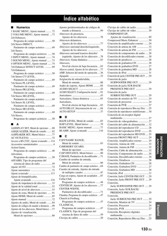
ÍNDICE ALFABÉTICOIN
FO
RM
AC
IÓN
A
DIC
ION
AL
Esp
año
l
Numerics1 BASIC MENU, Ajuste manual ......... 722 VOLUME MENU, Ajuste manual ... 732ch Enhancer,
Programa de campo acústico ........... 502ch Stereo DIRECT,
Parámetro de campo acústico .......... 692ch Stereo,
Programas de campos acústicos ...... 503 INPUT MENU, Ajuste manual ......... 743 SOUND MENU, Ajuste manual ....... 734 OPTION MENU, Ajuste manual ...... 747ch Enhancer EFFECT LEVEL .......... 697ch Enhancer,
Programa de campo acústico ........... 507ch Stereo CT LEVEL,
Parámetro de campo acústico .......... 697ch Stereo PL LEVEL,
Parámetro de campo acústico .......... 697ch Stereo PR LEVEL,
Parámetro de campo acústico .......... 697ch Stereo SB LEVEL,
Parámetro de campo acústico .......... 697ch Stereo SL LEVEL,
Parámetro de campo acústico .......... 697ch Stereo SR LEVEL,
Parámetro de campo acústico .......... 697ch Stereo,
Programas de campos acústicos ...... 50
AA)DISPLAY SET, Menú de opciones .... 88A)EQUALIZER, Menú de sonido ....... 82A)SPEAKER SET, Menú básico ......... 77AC OUTLET(S) .................................. 32Acceso a RS-232C, Ajuste avanzado .... 114Accesorios suministrados ...................... 4Action Game,
Programas de campos acústicos ...... 48Adventure,
Programas de campos acústicos ...... 50AFFAIRS, Tipo de programas del
sistema de datos de radio ................. 59Ajuste AUTO ....................................... 72Ajuste automático ................................ 72Ajuste avanzado ................................. 113Ajuste de biamplificador,
Ajuste avanzado ............................. 116Ajuste de impedancia de altavoces ...... 33Ajuste de la calidad tonal ..................... 52Ajuste de nivel de altavoces ................. 53Ajuste de zona, Menú de opciones ...... 91Ajuste HDMI, Menú de sonido ............ 85Ajuste manual ...................................... 72Ajustes de audio, Menú de sonido ....... 84Ajustes de códigos de mando a distancia ... 99Ajustes de los altavoces, Menú básico ... 77Ajustes de visualización,
Menú de opciones ............................ 88
Ajustes predeterminados de códigos de mando a distancia .............................99
Altavoces de presencia, Ajustes de los altavoces ...................78
Altavoces delanteros, Ajustes de los altavoces ...................77
Altavoces surround derecho/izquierdo, Ajustes de los altavoces ...................78
Altavoces surround traseros derecho/izquierdo, Ajustes de los altavoces ...78
Altavoces, Gama dinámica ...................83Altavoces,
Nivel de efectos de baja frecuencia ...83Altavoz central, Ajustes de los altavoces ...77AMP, Selector del modo de operación ....36Apagado ...............................................33Asignación de entrada/salida,
Menú de entrada ...............................86Audio de soporte, Ajuste HDMI ..........85AUDIO SELECT .................................43AUDIO SELECT, Configuración inicial ....91Auriculares ...........................................43Auriculares, Gama dinámica ................83Auriculares,
Nivel de efectos de baja frecuencia ...83AUTO DELAY, Sincronización de voz .....84AUTO SETUP .....................................37
BB)LFE LEVEL, Menú de sonido .........83B)SP LEVEL, Menú básico .................79BASIC MENU, Ajuste manual ............77BI-AMP, Ajuste avanzado .................116
CC)DYNAMIC RANGE,
Menú de sonido ................................83C)MEMORY GUARD,
Menú de opciones ............................90C)SP DISTANCE, Menú básico ..........80C.IMAGE, Parámetros de decodificador ...71Cambio de nombre de entrada,
Menú de entrada ...............................86Cambio de parámetro de campo acústico ...64Canales de entrada, Ajustes de entrada
de múltiples canales .......................... 87Carga en espera, Ajuste de acoplador ....87Cellar Club,
Programas de campos acústicos .......48CENTER SP, Ajustes de los altavoces ....77CENTER WIDTH,
Parámetros de decodificador ............71Chamber, Programas de campos acústicos ...47Church in Freiburg,
Programas de campos acústicos .......47CLASSICAL,
Programas de campos acústicos .......47CLASSICS, Tipo de programas del
sistema de datos de radio .................59Clavijas de cables .................................20
Clavijas de cables de audio .................. 20Clavijas de cables de vídeo .................. 20COMPONENT I/P,
Ajustes de visualización .................. 89Compressed Music Enhancer .............. 50Conexión de amplificador externo ...... 29Conexión de antena de AM ................. 32Conexión de antena de FM .................. 32Conexión de componentes de audio .... 28Conexión de decodificador externo ..... 30Conexión de giradiscos ........................ 28Conexión de grabadora CD ................. 28Conexión de grabadora DVD .............. 27Conexión de grabadora MD ................ 28Conexión de iPod ................................ 31Conexión de jacks CENTER PRE OUT .... 29Conexión de jacks
SUBWOOFER PRE OUT ............... 29Conexión de jacks SUR.BACK/
PRESENCE PRE OUT ................... 29Conexión de jacks
SURROUND PRE OUT ................. 29Conexión de monitor de TV ................ 24Conexión de proyector ........................ 24Conexión de PVR ................................ 27Conexión de reproductor Blu-ray Disc ... 25Conexión de reproductor multiformato ... 30Conexión de un receptor digital
multimedia ....................................... 27Conexión de videograbadora ............... 27Conexión del cable de alimentación .... 32Conexión del reproductor CD ............. 28Conexión del reproductor DVD .......... 26Conexión del reproductor HD DVD .... 25Conexión FRONT PRE OUT .............. 29Conexión, Amplificador externo ......... 29Conexión, Antena de AM .................... 32Conexión, Antena de FM .................... 32Conexión, Cable de alimentación ........ 32Conexión, Componentes de audio ....... 28Conexión, Decodificador externo ........ 30Conexión, Giradiscos .......................... 28Conexión, Grabadora CD .................... 28Conexión, Grabadora DVD ................. 27Conexión, Grabadora MD ................... 28Conexión, iPod .........................................31Conexión, Jacks CENTER PRE OUT .... 29Conexión, Jacks FRONT PRE OUT .... 29Conexión,
Jacks SUBWOOFER PRE OUT ..... 29Conexión, Jacks SUR.BACK/
PRESENCE PRE OUT ................... 29Conexión,
Jacks SURROUND PRE OUT ........ 29Conexión, Monitor de TV ................... 24Conexión, Proyector ............................ 24Conexión, PVR .................................... 27Conexión, Receptores digitales
multimedia ....................................... 27Conexión, Reproductor Blu-ray Disc ... 25
Índice alfabético
133 Es
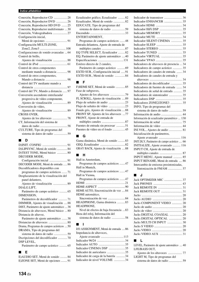
Índice alfabético
Conexión, Reproductor CD ................. 28Conexión, Reproductor DVD .............. 26Conexión, Reproductor HD DVD ....... 25Conexión, Reproductor multiformato ... 30Conexión, Videograbadora .................. 27Configuración inicial,
Menú de opciones ............................ 91Configuración MULTI-ZONE,
Zone2, Zone3 ................................. 108Configuraciones de sonido avanzadas ... 64Control de brillo,
Ajustes de visualización .................. 88Control de iPod .................................... 61Control de otros componentes
mediante mando a distancia ............. 98Control de otros componentes,
Mando a distancia ............................ 98Control del TV mediante mando a
distancia ........................................... 97Control del TV, Mando a distancia ...... 97Conversión ascendente entrelazada/
progresiva de vídeo componente, Ajustes de visualización .................. 89
Conversión de vídeo, Ajustes de visualización .................. 89
CROSS OVER, Ajustes de los altavoces ................... 78
CT, Información del sistema de datos de radio ................................... 58
CULTURE, Tipo de programas del sistema de datos de radio ................. 59
DD)INIT. CONFIG ................................ 91D)LIPSYNC, Menú de sonido ............. 84D)TEST TONE, Menú básico ............. 80DECODER MODE,
Configuración inicial ....................... 91DECODER MODE, Menú de entrada ..... 86Decodificadores disponibles con
programas de campos acústicos ....... 71Desplazamiento de la visualización del
panel delantero, Ajustes de visualización .................. 89
DIALG.LIFT, Parámetro de campo acústico .......... 65
DIMENSION, Parámetros de decodificador ........... 71
DIMMER, Ajustes de visualización .... 88DIST, Parámetro de ajuste automático ... 38Distancia de altavoces, Menú básico ... 80Distancia de altavoz,
Parámetro de ajuste automático ....... 38Distancias de altavoces ........................ 80Drama, Programas de campos acústicos ... 50DRAMA, Tipo de programas del
sistema de datos de radio ................. 59Dscripciones del decodificador ............ 70DSP LEVEL,
Parámetro de campo acústico .......... 65
EE)AUDIO SET, Menú de sonido ......... 84E)ZONE SET, Menú de opciones ........ 91
Ecualizador gráfico, Ecualizador .........82Ecualizador, Menú de sonido ...............82EDUCATE, Tipo de programas del
sistema de datos de radio .................59Encendido .............................................33ENTERTAINMENT,
Programas de campos acústicos .......48Entrada delantera, Ajuste de entrada de
múltiples canales ..............................87EQ TYPE SELECT, Ecualizador .........82EQ, Parámetro de ajuste automático ....40Especificaciones .................................131Estéreo directo de 2 canales,
Parámetro de campo acústico ..........69EXTD SUR., Configuración inicial .....91EXTD SUR., Menú de sonido .............84
FF)HDMI SET, Menú de sonido ............85Fase de subgraves,
Ajustes de los altavoces ...................79FL SCROLL, Ajustes de visualización ....89Flujo de señales de audio .....................23Flujo de señales de vídeo .....................23Fondo gris, Ajustes de visualización ....88FRONT SP, Ajustes de los altavoces ...77FRONT, Ajuste de entrada de
múltiples canales ..............................87Fuentes de entrada sin procesar ...........51Fuentes de vídeo en el fondo ................45
GGama dinámica, Menú de sonido .........83GEQ, Ecualizador ................................82GRAY BACK, Ajustes de visualización ....88
HHall in Amsterdam,
Programas de campos acústicos .......47Hall in Munich,
Programas de campos acústicos .......47Hall in Vienna,
Programas de campos acústicos .......47HDMI ...................................................21HDMI ASPECT ...................................90HDMI AUTO, Sincronización de voz ....84HDMI automático,
Sincronización de voz ......................84HEADPHONE, Gama dinámica ..........83HEADPHONE,
Nivel de efectos de baja frecuencia ...83Hora del reloj, Información del
sistema de datos de radio .................58
II/O ASSIGNMENT, Menú de entrada ....86Impedancia de altavoces,
Ajuste avanzado .............................113Indicador 96/24 ....................................34Indicador AUTO ..................................35Indicador CINEMA DSP .....................35Indicador de auriculares .......................35Indicador de carga de la batería ...........34Indicador de nivel VOLUME ..............34
Indicador de transmisor ....................... 36Indicador ENHANCER ....................... 35Indicador HDMI .................................. 34Indicador HiFi DSP ............................. 35Indicador MEMORY ........................... 35Indicador MUTE ................................. 34Indicador SILENT CINEMA .............. 35Indicador SLEEP ................................. 35Indicador STEREO .............................. 35Indicador TUNED ............................... 35Indicador VIRTUAL ........................... 35Indicador YPAO .................................. 35Indicadores de altavoces de presencia ... 34Indicadores de campo acústico ............ 35Indicadores de canales de entrada ....... 34Indicadores de canales de entrada y
altavoces .......................................... 34Indicadores de decodificador ............... 35Indicadores de fuentes de entrada ....... 34Indicadores de señal de entrada ........... 35Indicadores de sintonizador ................. 35Indicadores DSP .................................. 35Indicadores ZONE2/ZONE3 ............... 35INFO, Tipo de programas del
sistema de datos de radio ................. 59Información de audio ........................... 44Información de ecualizador paramétrico ... 130Información de señal ........................... 75Información de vídeo ........................... 44INI.VOL., Ajustes de audio ................. 81Inicialización de parámetros,
Ajuste avanzado ............................ 116INIT.DLY, Parámetro de campo acústico .... 66INITIALIZE, Ajuste avanzado .......... 116INPUT CH, Ajuste de entrada de
múltiples canales ............................. 87INPUT MENU, Ajuste manual ........... 85INPUT RENAME, Menú de entrada .... 86Intercambio de emisoras presintonizadas,
Sintonización de FM/AM .................. 57
JJack OPTIMIZER MIC ....................... 37Jack PHONES ..................................... 43Jack REMOTE IN ............................... 31Jack REMOTE OUT ........................... 31Jacks .................................................... 20Jacks AUDIO ...................................... 20Jacks COMPONENT VIDEO ............. 20Jacks de audio ...................................... 20Jacks de vídeo ...................................... 20Jacks DIGITAL COAXIAL ................ 20Jacks DIGITAL OPTICAL ................. 20Jacks MULTI CH INPUT ................... 30Jacks S VIDEO .................................... 20Jacks VIDEO ....................................... 20Jacks VIDEO AUX ............................. 31
LLEVEL, Parámetro de ajuste automático ... 40LFE/BASS OUT,
Ajustes de los altavoces .................. 77LIGHT M, Tipo de programas del
sistema de datos de radio ................. 59
134 Es

Índice alfabéticoIN
FO
RM
AC
IÓN
A
DIC
ION
AL
Esp
año
l
LIVE/CLUB, Programas de campos acústicos ...... 47
LIVENESS, Parámetro de campo acústico ... 67LVL, Parámetro de ajuste automático ... 38
MM.O.R. M, Tipo de programas del
sistema de datos de radio ................. 59Mando a distancia AMP ID,
Ajuste avanzado ............................. 114Mando a distancia TUNER ID,
Ajuste avanzado ............................. 114MANUAL DELAY,
Sincronización de voz ...................... 84MANUAL SETUP ............................... 72MASTER ON/OFF .............................. 33MAX VOL., Ajustes de audio ............. 81Memoria del sistema ............................ 75Menú básico, Ajuste manual ................ 72Menú de entrada, Ajuste manual ......... 74Menú de opciones, Ajuste manual ....... 74Menú de sonido, Ajuste manual .......... 73Menú de volumen, Ajuste manual ....... 73Micrófono optimizador ........................ 37Modo de decodificador,
Configuración inicial ....................... 91Modo de decodificador, Menú de entrada ... 86Modo de espera, zona principal ........... 33Modo de espera, Zone2, Zone3 ......... 110Modo PTY SEEK, Sintonización del
sistema de datos de radio ................. 59Modo STRAIGHT ............................... 51MON.CHK, Ajuste avanzado ............ 116Monitor de vídeo HDMI, Ajuste avanzado ... 116Mono Movie,
Programas de campos acústicos ...... 50MOVIE, Programas de campos acústicos .... 49MUSIC ENHANCER,
Categoría de campo acústico ........... 50Music Video,
Programas de campos acústicos ...... 49MUTE .................................................. 44
NNeo:6 Cinema, Tipo de decodificador ... 70, 71Neo:6 Music, Tipo de decodificador ... 70NEWS, Tipo de programas del
sistema de datos de radio ................. 59Nivel de altavoces, Menú básico ......... 79Nivel de altavoz central estéreo de 7 canales,
Parámetro de campo acústico ................ 69Nivel de altavoz de presencia derecho
estéreo de 7 canales, Parámetro de campo acústico .......... 69
Nivel de altavoz de presencia izquierdo estéreo de 7 canales, Parámetro de campo acústico .......... 69
Nivel de altavoz surround derecho estéreo de 7 canales, Parámetro de campo acústico .......... 69
Nivel de altavoz surround izquierdo estéreo de 7 canales, Parámetro de campo acústico .......... 69
Nivel de altavoz surround trasero estéreo de 7 canales, Parámetro de campo acústico ...........69
Nivel de altavoz, Parámetro de ajuste automático .......38
Nivel de efectos Compressed Music Enhancer de 7 canales, Parámetro de campo acústico ...........69
Nivel de efectos de baja frecuencia, Menú de sonido ................................83
Nivel de efectos Straight Compressed Music Enhancer, Parámetro de campo acústico ...........69
Nivel de reverberación, Parámetro de campo acústico ...........68
Nivel de sonido de efectos, Parámetro de campo acústico ...........65
Nivel de sonido, Parámetro de ajuste automático .......40
Número de altavoces, Parámetro de ajuste automático .......38
OOmisión de tono, Ajustes de audio ......84ON SCREEN, Ajustes de visualización ....88OPTION MENU, Ajuste manual .........88OSD cambio, Ajustes de visualización ....88OSD SHIFT, Ajustes de visualización ....88OTHER M, Tipo de programas del
sistema de datos de radio .................59
PP.INIT.DLY,
Parámetro de campo acústico ...........66P.ROOM SIZE,
Parámetros de campos acústicos ......67PANORAMA,
Parámetros de decodificador ............71Paso de frecuencias del sintonizador,
Ajuste avanzado .............................116PL II Game, Tipo de decodificador ......70PL II Movie, Tipo de decodificador .....70PL II Music, Tipo de decodificador .....70PLIIx Game, Tipo de decodificador .....70PLIIx Movie, Tipo de
decodificador ..............................70, 71PLIIx Music, Tipo de decodificador ....70POP M, Tipo de programas del
sistema de datos de radio .................59Posición de diálogo vertical,
Parámetro de campo acústico ...........65PRESENCE SP, Ajustes de los altavoces .....78Presintonización automática,
Sintonización de FM/AM ................55Presintonización manual,
sintonización de FM/AM .................55Prioridad del canal de presencia/surround
trasero, Ajustes de los altavoces .........79PRIORITY, Ajustes de los altavoces ...79PRO LOGIC, Tipo de decodificador ...70Procedimiento básico de reproducción ...42Programación de macros,
Mando a distancia ..........................105Programas de campos acústicos ...........46
Programas de campos acústicos con auriculares ....................................... 51
Programas de campos acústicos sin altavoces surround ........................... 51
Protección de la memoria, Menú de opciones ............................ 90
PS, Información del sistema de datos de radio .................................. 58
PTY, Información del sistema de datos de radio .................................. 58
Puerta del panel delantero ................... 36PURE DIRECT ................................... 52
RRC AMP ID, Ajuste avanzado .......... 114RC TUNER ID, Ajuste avanzado ...... 114Recital/Opera,
Programas de campos acústicos ...... 49Recorte de volumen, Menú de entrad ... 86Relación de aspecto HDMI ................. 90REMOTE SENSOR, Ajuste avanzado ... 113Repetición, Reproducción iPod ........... 62Reposición del sistema ...................... 124Reproducción aleatoria iPod ................ 62Reproducción de fuentes de múltiples
canales con auriculares .................... 51Reproducción de fuentes de múltiples
canales en estéreo de 2 canales ....... 53Retardo automático,
Sincronización de voz ..................... 84Retardo de reverberación,
Parámetro de campo acústico .......... 68Retardo inicial de sonido de presencia,
Parámetro de campo acústico .......... 66Retardo inicial de sonido surround trasero,
Parámetro de campo acústico ............. 66Retardo inicial de sonido surround,
Parámetro de campo acústico .......... 66Retardo inicial,
parámetro de campo acústico .......... 66Retardo manual, Sincronización de voz ... 84REV.DELAY,
Parámetro de campo acústico .......... 68REV.LEVEL,
Parámetro de campo acústico .......... 68REV.TIME, Parámetro de campo acústico ... 68ROCK M, Tipo de programas del
sistema de datos de radio ................. 59Roleplaying Game,
Programas de campos acústicos ...... 48ROOM SIZE,
Parámetros de campos acústicos ..... 67RS-232C STANDBY, Ajuste avanzado .... 114RT, Información del sistema de
datos de radio .................................. 58
SS.INIT.DLY,
Parámetro de campo acústico .......... 66S.LIVENESS,
Parámetro de campo acústico .......... 67S.ROOM SIZE,
Parámetros de campos acústicos ..... 67
135 Es

Índice alfabético
Salida de LFE/graves, Ajustes de los altavoces ................... 77
SB INI.DLY, Parámetro de campo acústico .......... 66
SB L/R SP, Ajustes de los altavoces .... 78SB LIVENESS,
Parámetro de campo acústico .......... 67SB ROOM SIZE,
Parámetros de campos acústicos ..... 67SCIENCE, Tipo de programas del
sistema de datos de radio ................. 59Sci-Fi, Programas de campos acústicos ... 49Selección de audio, Configuración inicial ... 91Selección de componente
MULTI CH INPUT ......................... 43Selección de emisoras presintonizadas ..... 56Selección de jacks de entrada de audio ... 43Selección de programas de campos
acústicos .......................................... 46Selección del tipo de ecualizador,
Ecualizador ...................................... 82Selección, Componente
MULTI CH INPUT ......................... 43Selección, Jacks de entrada de audio ... 43Selección, Tipo de programas del
sistema de datos de radio ................. 59Selector del modo de operación ........... 36Sensor de mando a distancia,
Ajuste avanzado ............................. 113Servicio de datos EON, Sintonización del
sistema de datos de radio .................... 60Servicio de programas, Información del
sistema de datos de radio ................. 58Servicio mejorado de datos de otras redes,
Sintonización del sistema de datos de radio ................................... 60
SHORT MESSAGE, Ajustes de visualización .................. 88
SIGNAL INFO .................................... 44Silenciamiento ..................................... 44SILENT CINEMA ............................... 51Sincronización de audio y vídeo,
Menú de sonido ............................... 84Sincronización de voz, Menú de sonido ... 84Sintonización automática,
sintonización de FM/AM ................. 54Sintonización de AM ........................... 54Sintonización de FM ............................ 54Sintonización del sistema de datos de
radio ................................................. 58Sintonización manual,
Sintonización de FM/AM ................ 54Solución de problemas ....................... 117Sonido hi-fi puro .................................. 52SOUND MENU, Ajuste manual .......... 82SOURCE, Selector del modo de operación ... 36SP, Parámetro de ajuste automático ..... 38SPEAKER IMP., Ajuste avanzado .... 113SPEAKER, Gama dinámica ................ 83SPEAKER,
Nivel de efectos de baja frecuencia ... 83Spectacle, Programas de campos acústicos ... 49SPORT, Tipo de programas del
sistema de datos de radio ................. 59
Sports, Programas de campos acústicos ...48Standard, Programas de campos acústicos ...49STANDBY CHARGE,
Ajuste de acoplador .........................87STEREO, Programas de campos acústicos ...50STRAIGHT ..........................................51Straight Enhancer EFFECT LEVEL ....69SUBWOOFER PHASE,
Ajustes de los altavoces ...................79SUPPORT AUDIO, Ajuste HDMI ......85SUR. L/R SP, Ajustes de los altavoces ...78SURROUND DECODE,
Categoría de decodificador ..............70Surround expandido,
Configuración inicial .......................91Surround expandido, Menú de sonido ...84
TTamaño de habitación para
sonido de presencia, Parámetro de campo acústico ..........67
Tamaño de habitación para sonido surround trasero, Parámetro de campo acústico ..........67
Tamaño de habitación para sonido surround, Parámetro de campo acústico ..........67
Tamaño de habitación, Parámetros de campos acústicos ......67
Temporizador para dormir ...................45TEST, Ecualizador ...............................82Texto de radio, Información del
sistema de datos de radio .................58The Bottom Line,
Programas de campos acústicos .......48The Roxy Theatre,
Programas de campos acústicos .......48Tiempo de reverberación,
Parámetro de campo acústico ..........68Tiempo de visualización en pantalla,
Ajustes de visualización ...................88Tipo de ecualizador paramétrico,
Parámetro de ajuste automático .......40Tipo de programas, Información del
sistema de datos de radio .................58TONE BYPASS, Ajustes de audio ......84Tono de prueba, Ecualizador ...............82Tono de prueba, Menú básico ..............80Transición de graves,
Ajustes de los altavoces ...................78TUNER FRQ STEP, Ajuste avanzado .....116TV, Selector del modo de operación ....36
UUnidad, Distancia de altavoces ............80UNIT, Distancia de altavoces ..............80Usando el mando a distancia ................36Uso de iPod ..........................................61Uso de SET MENU ..............................76Utilización de auriculares .....................43
VVARIED, Tipo de programas del
sistema de datos de radio .................59
Ventana de infrarrojos ......................... 36VIDEO CONV., Ajustes de visualización .... 89Village Vanguard,
Programas de campos acústicos ...... 47Virtual CINEMA DSP ......................... 51Visualización de información de las
fuentes de entrada ............................ 44Visualización de mensajes breves,
Ajustes de visualización .................. 88Visualizador de información múltiple ... 34Vivacidad de sonido surround trasero,
Parámetro de campo acústico .......... 67Vivacidad de sonido surround,
Parámetro de campo acústico .......... 67Vivacidad, Parámetro de campo acústico ... 67VOLTAGE SELECTOR ....................... 5VOLUME TRIM, Menú de entrad ...... 86Volumen inicial, Ajustes de audio ...... 81Volumen máximo ................................ 81Volumen máximo, Ajustes de audio ... 81
WWarehouse Loft,
Programas de campos acústicos ...... 47
“AMASTER ON/OFF” o “1DVD” (ejemplo) indica el nombre de las partes del panel delantero o del mando a distancia. Para conocer información de cada posición de las partes, consulte la hoja adjunta o las páginas al final de este manual.
136 Es
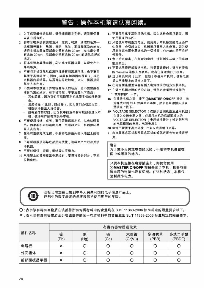
ØŸ÷Ýץݕ½Õ¼¶ƒ‹
Zh
1 为了保证 佳的性能,请仔细阅读本手册。请妥善保管以备日后查阅。
2 将本音响系统安装在通风,凉爽,乾燥,清洁的地方—远离阳光直射,热源,振动,肮脏,潮湿和寒冷的地方。请将本机放置在顶部 少留有余地 30 cm,左右 少留有余地 20 cm,后部 少留有余地 20 cm 的通风良好的地方。
3 将本机远离其他电器,马达或变压器放置,以避免产生蜂鸣噪声。
4 不要将本机突然从低温环境转移到高温环境,也不要将其置于高湿场所 (例如,放置有加湿器的房间),以防止机器内部结露。结露可能导致触电,火灾,机器损坏甚至人员伤害。
5 不要将本机放置于异物容易落入的场所,也不要放置在液体飞溅的地方。在本机顶部,不要放置以下物品:- 其他装置,因为它们可能损害本机或使本机的外表变
色。- 易燃物品 (比如,腊烛等),因为它们会引起火灾,
机器损坏甚至人员伤害。- 盛有液体的容器,因为其中的液体有可能倾倒进入本
机,使得用户触电或损坏本机。6 不要使用报纸,桌布,窗帘等物遮盖本机,以免妨碍散
热。如果本机内部温度升高,会引起火灾,机器损坏甚至人员伤害。
7 在所有连接完成之前,不要将电源插头插入墙壁上的插座。
8 不可将机器顶部与底部反向放置,这样会产生过热并损坏机器。
9 不要对螺钉,旋钮,缆线等过度施力。10 从墙壁上的插座拔出电源线时,要握持插头部分,不能
拉拽电线。
11 不要使用化学溶剂清洗本机。因为这样会损坏表层。请使用乾净的布匹。
12 只能使用本机指定电压。使用高于本机额定的电压会产生危险,会引起火灾,机器损坏甚至人员伤害。因为使用非指定电压电源造成的一切损害,Yamaha 将不负任何责任。
13 为了防止雷击,在打雷闪电时,请将插头从墙上的电源插座拔出。
14 不要试图修理或改造本机。当需要维修时,请与有资格的 Yamaha 维修人员联系。没有任何理由打开机壳。
15 当计划长时间 (比如,假期)不使用本机时,请将电源插头从墙壁上的插座上拔下。
16 在电源插座附近或容易插入电源插头的地方安装本机。17 在做出机器故障的结论之前,请务必参考通常操作的
“ 故障排除” 一节。18 在移动本机之前,按下AMASTER ON/OFF 按钮,向
外释放它到 OFF 位置关闭本机,然后将电源插头从墙壁插座上拔下。
19 VOLTAGE SELECTOR (仅限于亚洲机型及通用机型)在插入交流电源之前,必须将本机的后部面板上的 VOLTAGE SELECTOR (电压选择开关)设定到与当地电源相同的电压。电源电压为:
20 电池不能置于高热环境 , 比如火或直射日光等。21 来自耳塞式耳机和双耳式耳机的额外声压也许会损害听
力。
: 表示该有毒有害物质在该部件所有均质材料中的含量均在 SJ/T 11363-2006 标准规定的限量要求以下。× : 表示该有毒有害物质至少在该部件的某一均质材料中的含量超出 SJ/T 11363-2006 标准规定的限量要求。
警告:操作本机前请认真阅读。
警告为了减小火灾或电击的风险,不要将本机暴露在雨中或潮湿的地方。
只要本机连接在电源插座上,即使您使用AMASTER ON/OFF 按钮关闭了本机,机器与交流电源的连接也没有切断。在这种状态,本机仅消耗微小电力。
部件名称有毒有害物质或元素
铅(Pb)
汞(Hg)
镉(Cd)
六价铬(Cr(VI))
多溴联苯(PBB)
多溴二苯醚(PBDE)
电路板 ×
外壳箱体 ×
前部面板显示器 ×
该标记附加在出售到中华人民共和国的电子信息产品上。环形中的数字表示的是环境保护使用期限的年数。10

1 Zh
准备
前言
基本
操作
高级
操作
补充
信息
中文
APPEND
IX
注意 ................................................................. 2特性 ................................................................. 3
提供的配件 ........................................................4开始 ................................................................. 5快速开始指南 ................................................... 6
连接 ............................................................... 12为您的听音室优化扬声器设置 ........................ 37
使用 AUTO SETUP .........................................37
播放 ............................................................... 42基本过程 ..........................................................42选择视频输入插孔 (AUDIO SELECT) ..............43选择 MULTI CH INPUT 组件机 ........................43使用您的耳机 ...................................................43默音音频输出 ...................................................44显示输入源的信息 (SIGNAL INFO) .................44在音源背景中播放视频源 .................................45使用睡眠定时器 ...............................................45
声场程序 ........................................................ 46选择声场程序 ...................................................46声场程序说明 ...................................................46欣赏未处理的输入源 ........................................51
使用音频功能 ................................................. 52欣赏纯正高保真音响 ........................................52调节音调质量 ...................................................52调节扬声器水平 ...............................................53以 2 声道立体声欣赏多声道音源 ......................53
FM/AM 调谐 ................................................... 54自动调谐 ..........................................................54手动调谐 ..........................................................54自动预设调谐 ...................................................55手动预设调谐 ...................................................55选择预设电台 ...................................................56交换预设电台 ...................................................57
无线电数据系统调谐( 仅限英国和欧洲型号 ) .............................. 58显示无线电数据系统信息 .................................58选择无线电数据系统节目类型
(PTY SEEK 模式) .....................................59使用加强的其他网络 (EON)数据服务 ..........60
使用 iPodTM 插孔 ........................................... 61控制 iPodTM .....................................................61
录制 ............................................................... 63
高级音响配置 ................................................. 64改变声场参数设置 ........................................... 64选择解码器 ..................................................... 69
定制本机 (MANUAL SETUP) ..................... 72使用 SET MENU ............................................. 761 BASIC MENU .............................................. 772 VOLUME MENU .......................................... 813 SOUND MENU ............................................ 824 INPUT MENU .............................................. 855 OPTION MENU ........................................... 88
保存和调出本机的系统设置(SYSTEM MEMORY) ................................. 93保存当前系统设置 ........................................... 93装载保存的系统设置 ....................................... 94用例 ................................................................ 95
遥控器功能 ..................................................... 97操作本机,电视机,或其他组件机 ................. 97设置遥控器代码 .............................................. 99编程其他遥控器的代码 ................................. 101在显示窗上改变源名称 ................................. 102宏指令编程功能 ............................................ 103清除配置 ....................................................... 106
使用多区域配置 ............................................ 108连接 Zone 2 和 Zone 3 视频装置 .................. 108控制 Zone 2 或 Zone 3 .................................. 109
高级设置 ...................................................... 113使用高级设置菜单 ......................................... 113
故障排除 ...................................................... 117系统复位 ...................................................... 124术语 .............................................................. 125声场程序信息 ............................................... 129参数均衡器信息 ............................................ 130规格 .............................................................. 131索引 .............................................................. 133
( 在本说明书的末尾 )
前部面板 ............................................................ i遥控器............................................................... ii各声场程序的声音输出......................................iii遥控器代码列表................................................. v
目录
前言
准备
基本操作
高级操作
补充信息
APPENDIX ( 附录 )
“ AMASTER ON/OFF” 或 “ 1DVD” ( 例 ) 指示的是前面板或遥控器的部件名称。关于各个部件的相关信息,请参考本说明书末尾附带的清单或页面。

注意
经 Dolby Laboratories 授权生产。“ Dolby” ,“ Pro Logic” 和双 D 标志均为 Dolby Laboratories 商标。
本产品的生产得到以下美国专利许可: 5,451,942;5,956,674;5,974,380;5,978,762;6,226,616;6,487,535 以及其他美国和世界范围所颁布的或正在申请的专利。 DTS 是 DTS, Inc. 的注册商标; DTS 标记,符号,DTS-HD 和 DTS-HD Master Audio 是 DTS, Inc. 的商标, ©1996-2007 DTS, Inc. 版权所有。
“ iPod” 是 Apple Inc. 的商标 , 在美国和其他国家注册。
“ HDMI” , “ HDMI” 标记和 “ High-Definition Multimedia Interface” 是 HDMI Licensing LLC 的商标和注册商标。
“ SILENT CINEMA” 是 YAMAHA CORPORATION 的商标。
注意
关于本说明书
• y 指示有关您的操作的提示。
• 有些操作能通过使用前面板上或遥控器上的按钮来执行。如果前面板上和遥控器上的按钮的名称不同,遥控器上的按钮的名称在圆括号内给出。
• 本说明书是在产品生产之前印刷的。由于改进等原因,设计和规格可能会有部分变更。如果说明书和产品存在不同,以产品为准。
• “ AMASTER ON/OFF” 或“ 1DVD” ( 例 ) 指示的是前面板或遥控器的部件名称。关于各个部件的相关信息,请参考本说明书末尾附带的清单或页面。
• 符号 “ ” 并附带数字指示的是相关的参考页码。
• 本说明书中插图 (例如,扬声器端子,输入 / 输出插孔,交流插座等)的形状根据型号也许不同。
iPodTM
2 Zh

特性前
言中
文
内置 7 声道功率放大器 小 RMS 输出功率
(20 Hz 到 20 kHz, 0.04% THD, 8 Ω)前置扬声器:130 W + 130 W中央扬声器:130 W环绕声扬声器:130 W + 130 W后环绕声扬声器:130 W + 130 W
声场程序 用于创建声场的专有 Yamaha 技术 Compressed Music Enhancer 模式可改善音响质量,减
少其中的压缩缺陷 (比如 MP3 格式的),使之达到高质量多声道音源播放的水平
Virtual CINEMA DSP SILENT CINEMA
数码音频解码器 Dolby TrueHD, Dolby Digital Plus 解码器 DTS-HD Master Audio, DTS-HD High Resolution Audio
解码器 Dolby Digital/Dolby Digital EX 解码器 DTS/DTS-ES Matrix 6.1, Discrete 6.1, DTS 96/24 解码器 Dolby Pro Logic/Dolby Pro Logic II/Dolby Pro Logic IIx 解
码器 DTS NEO:6 解码器
尖端的 FM/AM 调谐器 40 个电台的随机访问预设调谐 自动预设调谐 预设电台漂移能力 ( 预设编辑 ) 无线电数据系统能力 ( 仅限英国和欧洲型号 )
HDMITM( 高分辨率多媒体界面 ) 基于 HDMI 版本 1.3a,用于标准,加强或高分辨率视频以
及多声道数码音频的 HDMI 界面 自动音频和视频同步 (对口形)信息功能 Deep Color 视频信号 (30/36 比特)传输能力 高刷新率和高分辨率视频信号能力 高清晰度数码音频格式信号能力 用于监视输出的模拟视频到 HDMI 数码视频的内部转换
( 组合视频 ↔ S 视频 ↔ 分量视频 → HDMI 数码视频 ) 从 480i (NTSC)/576i (PAL) 或 480p/576p 到 720p,1080i
或 1080p 的模拟视频提升
iPodTM 控制能力 DOCK 端子用于连接 Yamaha iPod 多用平台(比如 YDS-
10,另售),可以支持 iPod (Click and Wheel),iPod nano 以及 iPod mini
其它特性 YPAO (Yamaha Parametric Room Acoustic Optimizer)
用于扬声器自动设置 192-kHz/24 比特 D/A 转换器 您可以使用 OSD( 在屏显示 ) 菜单,根据自己的视听系统
对本机进行优化设置 6 或 8 个额外的输入插孔,用于分散多声道输入 从 480i (NTSC)/576i (PAL) 到 480p (NTSC)/576p (PAL)
的模拟视频隔行 / 逐行转换 S 视频信号输入 / 输出能力 包括分量视频信号输入 / 输出能力
(3 个 COMPONENT VIDEO IN 和 1 个 MONITOR OUT) 光纤和同轴数码音频信号插孔 Pure Direct 模式用于纯高保真音响和所有音源 自适应动态范围控制能力 自适应 DSP 效果水平控制能力 带预设遥控器代码,学习和宏指令能力的遥控器 ZONE 2/ZONE 3 常规安装设施 区域切换功能可使用 ZONE CONTROLS 在主区域和
ZONE 2/ZONE 3 之间切换 为了保存和恢复多系统参数设置的 SYSTEM MEMORY
能力 睡眠定时器
特性
3 Zh
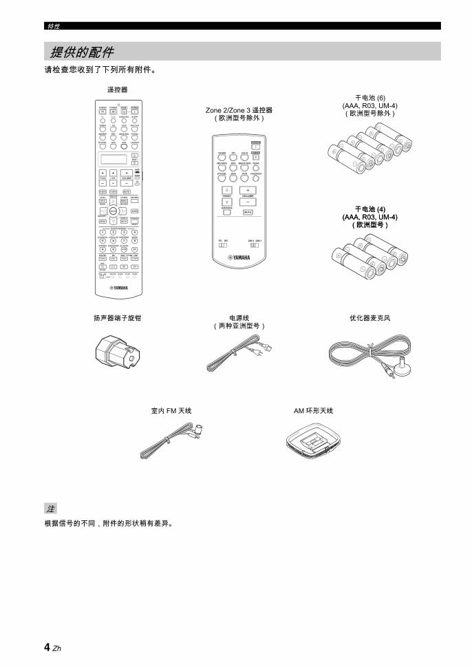
特性
请检查您收到了下列所有附件。
根据信号的不同,附件的形状稍有差异。
提供的配件
注
遥控器干电池 (6)
(AAA, R03, UM-4)( 欧洲型号除外 )
AM 环形天线
优化器麦克风扬声器端子旋钳 电源线(两种亚洲型号)
室内 FM 天线
TUNER CD CD-R
MD/TAPE DVD BD/HD DVD PHONO
DTV/CBL VCR V-AUX/DOCKDVR
POWER
STANDBY
A/B/C/D/E
PRESET VOLUME
ZONE 3ZONE 2ID2ID1
MUTE
Zone 2/Zone 3 遥控器( 欧洲型号除外 )
干电池 (4) (AAA, R03, UM-4)
( 欧洲型号 )
干电池 (4) (AAA, R03, UM-4)
( 欧洲型号 )
–
+ +
––
+
ENTER
DISPLAY
AUDIO
MENUTITLE
TV MUTE TV INPUT MUTE
432
ENT+1009
5
1
AVTV
76 8
RETURN
ONOFF CLEARLEARN RENAMEMACRO
REC
DISC SKIP
VOLUMECHTV VOL
EFFECT
PARAMETER
FREQ/TEXT EON MODE – PTY SEEK – START
STRAIGHTA/B/C/D/E
SRCH MODE
PURE DIRECTPRESET/CH
SET MENU
BAND
LEVEL
CLASSICAL LIVE/CLUB ENTERTAIN MOVIE
SYSTEM MEMORY
SUR. DECODEENHANCERSTEREO
TV
SOURCE
AMP
SELECT
DTV/CBL VCRDVR V-AUX/DOCK
TUNER CD CD-R MULTI CH IN
POWER POWER POWERSTANDBY
SLEEPAUDIO SEL
DVD BD/HD DVD PHONOMD/TAPE
4 Zh

开始前
言中
文
安装遥控器电池
1 请按 部分并将电池舱盖滑开。
2 请按照位于电池舱内侧的极性标记 (+ 和 -),插入四节随机附带的电池 (AAA, R03, UM-4)。
3 将电池舱盖滑回并直到将其卡入位。
在 Zone 2/Zone 3 遥控器里安装电池(欧洲型号除外)
1 打开电池舱盖。
2 请按照位于电池舱内侧的极性标记 (+ 和 -),插入两节随机附带的电池 (AAA, R03, UM-4)。
3 将电池舱盖返回原位。
• 如果有以下情况,请更换所有电池:- 遥控器的操作距离减小。- 传输指示器 (O) 不闪烁或变暗。
• 新旧电池请勿混用。• 请勿将不同型号的电池一起使用 (例如碱性电池和锰电
池)。请仔细阅读包装,因为这些不同类型的电池可能具有相同的外形和颜色。
• 如果电池漏液,请立即将其处理掉。请勿触摸泄漏的物质或让其接触到衣服等。在安装新电池之前,请彻底清洁电池舱。
• 不要将电池与家庭垃圾混同在一起丢弃;请按照所在地的规定丢弃电池。
• 如果遥控器中没有电池超过 2 分钟,或如果将耗尽的电池留在遥控器内,存储器的内容将被清除。当存储器被清除时,请插入新电池,设置遥控代码并对任何已学习到的但可能已经被清除的功能进行编程。
VOLTAGE SELECTOR(仅限亚洲和通用型号)
开始
13
2
1 3
2
注
警告在您将电源插头插入墙壁的交流电源之前,本机后部面板上的 VOLTAGE SELECTOR 必须要根据您当地的主电压设置。不妥当的 VOLTAGE SELECTOR 设置将会损坏本机并可能造成火灾。使用平板螺丝刀顺时针或逆时针旋转 VOLTAGE SELECTOR。电压如下:
AC 110/120/220/230-240 V, 50/60 Hz
230-240V
VOLTAGESELECTOR
电压指示
5 Zh
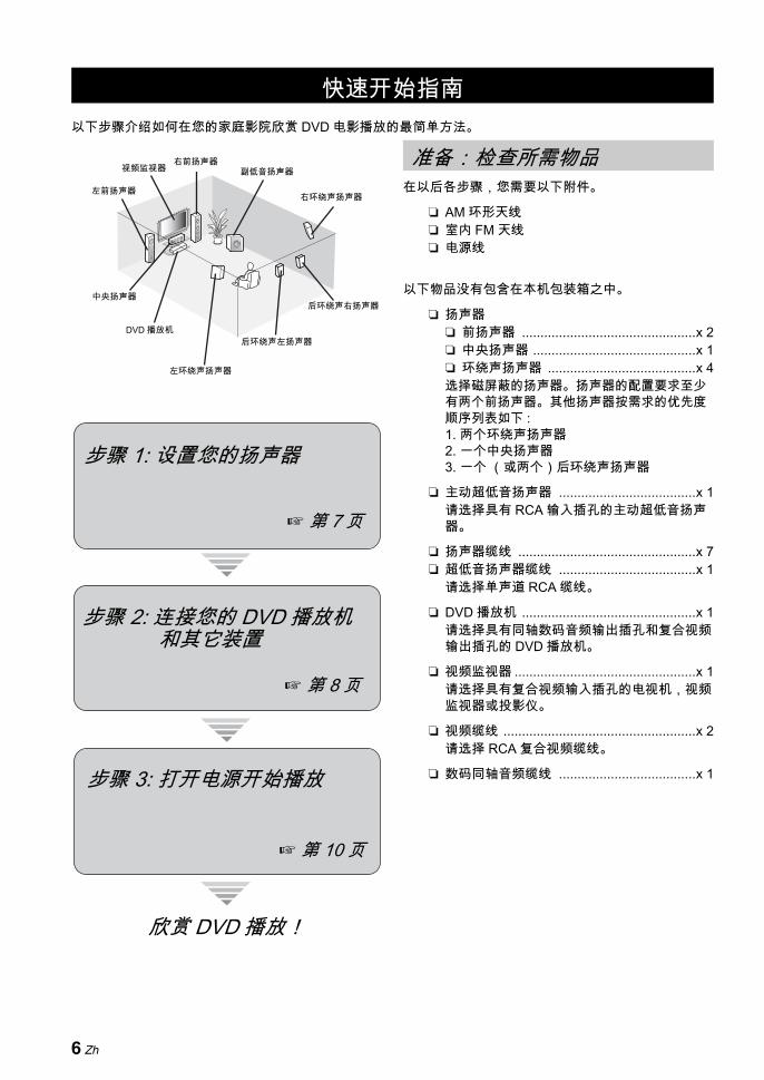
快速开始指南
以下步骤介绍如何在您的家庭影院欣赏 DVD 电影播放的 简单方法。
在以后各步骤,您需要以下附件。
AM 环形天线 室内 FM 天线 电源线
以下物品没有包含在本机包装箱之中。
扬声器 前扬声器 ...............................................x 2 中央扬声器 ............................................x 1 环绕声扬声器 ........................................x 4选择磁屏蔽的扬声器。扬声器的配置要求至少有两个前扬声器。其他扬声器按需求的优先度顺序列表如下 :1. 两个环绕声扬声器2. 一个中央扬声器3. 一个 (或两个)后环绕声扬声器
主动超低音扬声器 .....................................x 1请选择具有 RCA 输入插孔的主动超低音扬声器。
扬声器缆线 ................................................x 7 超低音扬声器缆线 .....................................x 1
请选择单声道 RCA 缆线。
DVD 播放机 ...............................................x 1请选择具有同轴数码音频输出插孔和复合视频输出插孔的 DVD 播放机。
视频监视器 .................................................x 1请选择具有复合视频输入插孔的电视机,视频监视器或投影仪。
视频缆线 ....................................................x 2请选择 RCA 复合视频缆线。
数码同轴音频缆线 .....................................x 1
快速开始指南
右前扬声器副低音扬声器
后环绕声右扬声器
左环绕声扬声器
左前扬声器
后环绕声左扬声器
右环绕声扬声器
中央扬声器
视频监视器
DVD 播放机
欣赏 DVD 播放!
步骤 1: 设置您的扬声器
第 7 页
步骤 2: 连接您的 DVD 播放机和其它装置
步骤 3: 打开电源开始播放
第 8 页
第 10 页
准备: 检查所需物品
6 Zh
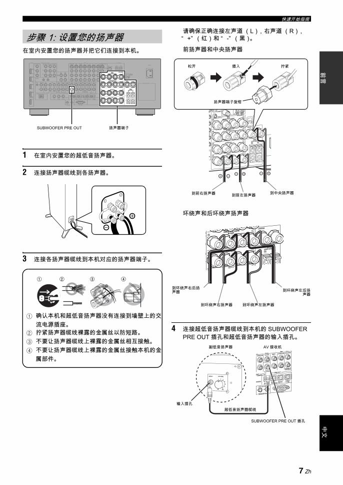
快速开始指南前
言中
文
在室内安置您的扬声器并把它们连接到本机。
1 在室内安置您的超低音扬声器。
2 连接扬声器缆线到各扬声器。
3 连接各扬声器缆线到本机对应的扬声器端子。
1 确认本机和超低音扬声器没有连接到墙壁上的交流电源插座。
2 拧紧扬声器缆线裸露的金属丝以防短路。3 不要让扬声器缆线上裸露的金属丝相互接触。4 不要让扬声器缆线上裸露的金属丝接触本机的金
属部件。
请确保正确连接左声道 (L),右声道 (R),“ +” (红)和 “ -” (黑)。
前扬声器和中央扬声器
环绕声和后环绕声扬声器
4 连接超低音扬声器缆线到本机的 SUBWOOFER PRE OUT 插孔和超低音扬声器的输入插孔。
步骤 1: 设置您的扬声器
AC IN
AC OUTLETS
HOLDERWRENCH
SPEAKERS
CENTERBI-AMP
SURROUND BACK/
PRESENCE/ZONE 2/ZONE 3SP1
FRONT
SURROUNDZONE 2/ZONE 3
SINGLE
SP2
ANTENNA
FM GND AM75Ω UNBAL.
VIDEO
S VIDEO
MONITOR OUTVIDEO
REMOTE
PHONOGND CD
IN(PLAY) OUT(REC)
CD-R
HDMI COMPONENT VIDEO
AUDIODOCK DIGITAL INPUT
MULTI CH INPUT PRE OUT
TRIGGER OUT RS-232C
DIGITAL OUTPUTZONE OUT
SUBWOOFER
SUBWOOFER
CENTER CENTERFRONT(6CH) FRONTSURROUND SURROUND
PRESENCESUR.BACK/
SINGLE(SB) ZONE 2 ZONE 3
CD DVD DVR
COAXIAL
1 2
CD BD/HD DVD
DTV/CBL
MD/ TAPEDVD CD-R
OPTICAL
987654321
SB(8CH)
DVD
TAPEMD/
(REC)(PLAY)IN OUT
BD/HD DVD VCRDVRDTV/CBL OUT OUTININBD/HD DVD DVD DTV/CBLMONITOR OUT
Y
PR
Y
PR
PB PB
IN OUT
DVR
DTV/CBL
DVD
BD/HD DVD
OUT
+
+ +
A B C
R L
R
R
L
R
L
+ + +R L
+ +R L
+ +R L
L
IN2
IN3
IN4
IN1
SUBWOOFER PRE OUT 扬声器端子
1 2 3 4
1 2 3 4
到前左扬声器到前右扬声器
松开 插入 拧紧
到中央扬声器
扬声器端子旋钳
到环绕声右后扬声器 到环绕声左后扬
声器
到环绕声右扬声器 到环绕声左扬声器
SUBWOOFER PRE OUT 插孔
输入插孔
AV 接收机副低音扬声器
超低音扬声器缆线
7 Zh
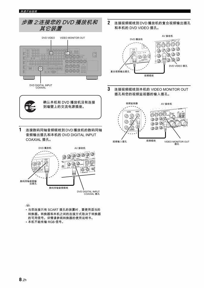
快速开始指南
1 连接数码同轴音频缆线到 DVD 播放机的数码同轴音频输出插孔和本机的 DVD DIGITAL INPUT COAXIAL 插孔。
y• 当您连接只有 SCART 插孔的装置时,要使用适当的
转换器。转换器和本机之间的连接方式取决于转换器的可用信号。详情请参阅转换器的使用说明书。
• 本机不能传输 RGB 信号。
2 连接视频缆线到 DVD 播放机的复合视频输出插孔和本机的 DVD VIDEO 插孔。
3 连接视频缆线到本机的 VIDEO MONITOR OUT 插孔和您的视频监视器的输入插孔。
步骤 2:连接您的 DVD 播放机和其它装置
AC IN
AC OUTLETS
HOLDERWRENCH
SPEAKERS
CENTERBI-AMP
SURROUND BACK/
PRESENCE/ZONE 2/ZONE 3SP1
FRONT
SURROUNDZONE 2/ZONE 3
SINGLE
SP2
ANTENNA
FM GND AM75Ω UNBAL.
VIDEO
S VIDEO
MONITOR OUTVIDEO
REMOTE
PHONOGND CD
IN(PLAY) OUT(REC)
CD-R
HDMI COMPONENT VIDEO
AUDIODOCK DIGITAL INPUT
MULTI CH INPUT PRE OUT
TRIGGER OUT RS-232C
DIGITAL OUTPUTZONE OUT
SUBWOOFER
SUBWOOFER
CENTER CENTERFRONT(6CH) FRONTSURROUND SURROUND
PRESENCESUR.BACK/
SINGLE(SB) ZONE 2 ZONE 3
CD DVD DVR
COAXIAL
1 2
CD BD/HD DVD
DTV/CBL
MD/ TAPEDVD CD-R
OPTICAL
987654321
SB(8CH)
DVD
TAPEMD/
(REC)(PLAY)IN OUT
BD/HD DVD VCRDVRDTV/CBL OUT OUTININBD/HD DVD DVD DTV/CBLMONITOR OUT
Y
PR
Y
PR
PB PB
IN OUT
DVR
DTV/CBL
DVD
BD/HD DVD
OUT
+
+ +
A B C
R L
R
R
L
R
L
+ + +R L
+ +R L
+ +R L
L
IN2
IN3
IN4
IN1
确认本机和 DVD 播放机没有连接到墙壁上的交流电源插座。
VIDEO MONITOR OUTDVD VIDEO
DVD DIGITAL INPUT COAXIAL
数码同轴音频输出插孔
数码同轴音频缆线DVD DIGITAL INPUT
COAXIAL 插孔
DVD 播放机 AV 接收机
复合视频输出插孔视频缆线
DVD VIDEO 插孔
DVD 播放机AV 接收机
视频监视器 AV 接收机
视频缆线 VIDEO MONITOR OUT插孔
视频输入插孔
8 Zh

快速开始指南前
言中
文
4 连接附带的 AM 环形天线和室内 FM 天线到本机。
根据型号的不同,本机附带的室内 FM 天线类型和 FM天线端子有可能不同。
连接 AM 环状天线的导线
yAM 环形天线不具有极性,所以可以连接任何一端到AM 或 GND 端子。
组装附带的 AM 环形天线
5 将本机附带的电源缆线插入本机,然后将电源线和其他装置的电源插头连接到墙壁上的交流电源插座。y• 本机具有为其他装置提供电源的 AC OUTLET(S)(韩国型号除外)。有关详情请参阅第 32 页。
•(仅限于亚洲型号)在将本机连接到墙壁上的交流电源插座之前,请在附带的电源缆线中选择适合于您所在地区的交流电源插座类型的缆线。
注
室内 FM 天线
AM 环形天线
按住舌片 插入 释放舌片
有关其他连接• 使用其他类型的扬声器组合 第 14 页
• 以不同方式连接视频监视器 第 24 页
• 以不同方式连接 DVD 播放机 第 25 页
• 连接 DVD 刻录机或数码视频录像机 第 27 页
• 连接置顶盒 第 27 页
• 连接 CD 播放机,MD 录音机或电唱机 第 28 页
• 连接外部放大器 第 29 页
• 通过模拟多声道音频方式连接 DVD 播放机 第 30 页
• 连接 Yamaha iPod 多用平台 第 31 页
• 使用 REMOTE IN/OUT 插孔 第 31 页
• 使用在前面板的 VIDEO AUX 插孔 第 31 页
• 连接室外 FM/AM 天线 第 32 页
综合连接信息• 插孔和缆线插头的综合信息 第 20 页
• HDMI 的综合信息 第 21-22 页
• 扬声器阻抗设置 第 33 页
9 Zh

快速开始指南
1 打开连接到本机的视频监视器。
2 向内按下前面板上的AMASTER ON/OFF按钮到 ON 位置。
3 旋转CINPUT 选择旋钮,来设置 “ DVD” 作为输入源。y• 对于每一个输入源 (DVD 等),推荐的声场程序被设
置。 您也可以使用不同的声场程序和其他的声音模式来播放。 有关详情请参阅以下几页:- 使用各种声场程序,请参阅第 46-50 页- 打开或关闭声音效果,请参阅第 51 页- 使用 Pure Direct 模式以得到高保真音响,请参阅
第 52 页• 您也可以设置输入源到“ TUNER” ,来使用 FM/AM 调
谐性能。关于 FM/AM 调谐信息,请参阅第 54-57 页。
4 在您的播放机上开始播放期望的 DVD。
5 按下QVOLUME,调节音量。
使用本机之后 ...
按下BMAIN ZONE ON/OFF,设置本机到待机模式。
本机设置为待机模式,此时,本机消耗少量电力,以随时接收来自遥控器的红外线信号。要从待机模式打开本机时,按下前面板的BMAIN ZONE ON/OFF ( 或遥控器上的 8POWER)。有关详情请参阅第 33页。
步骤 3: 打开电源开始播放检查所连接的扬声器类型。如果扬声器是 6 欧姆扬声器,在使用本机之前,设置 “ SPEAKER IMP.” 到 “ 6Ω MIN” ( 请参阅第 33 页 )。4 欧姆扬声器也可以用作前方扬声器(请参阅第 113 页)。
10 Zh

快速开始指南前
言中
文
t您想使用本机做什么?使用各种输入源
• 本机的基本操作 第 42 页
• 欣赏 FM/AM 广播节目 第 54 页
• 欣赏无线电数据系统节目 第 58 页
• 在本机使用 iPod 第 61 页
使用各种音响功能• 使用各种声场程序 第 46 页
• 使用 Pure Direct 模式以得到高保真音响 第 52 页
• 调节扬声器的音调质量 第 52 页
• 定制声场程序 第 64 页
调节本机的参数• 为您的听音室自动优化扬声器参数
(AUTO SETUP) 第 37 页
• 设置遥控器 第 97 页
附加功能• 要在 OSD 上显示当前输入源的信号信息
第 44 页
• 保存和调出本机的系统设置(SYSTEM MEMORY) 第 93 页
• 使用耳机 第 43 页
• 在多个房间同时使用本机(多区域配置) 第 108 页
• 自动关闭本机 第 45 页
手动调节本机的各种参数• 设置基本扬声器配置 第 77 页
• 调节扬声器水平的平衡 第 79 页
• 设置各个扬声器的距离 第 80 页
• 设置有关音量水平的参数 第 81 页
• 使用图形均衡器调节音调质量 第 82 页
• 对于 HDMI 连接调节口形同步功能 第 84 页
• 指定本机的输入 / 输出插孔 第 86 页
• 设置前面板显示器或 OSD 的参数 第 88 页
• 设置有关视频信号的参数 第 89 页
• 保护各种设置 第 90 页
• 设置多区域功能的参数 第 91 页
调节高级参数• 设置所连接扬声器的扬声器阻抗 第 113 页
• 设置本机的参数到缺省值 第 116 页
11 Zh

0 TRIGGER OUT 插孔有几个定制安装使用的控制扩展端子。
A RS-232C 端子这是一个工厂专用的控制扩展端子。 详情请咨询您的经销商。
连接
后部面板
AC IN
AC OUTLETS
HOLDERWRENCH
SPEAKERS
CENTERBI-AMP
SURROUND BACK/
PRESENCE/ZONE 2/ZONE 3SP1
FRONT
SURROUNDZONE 2/ZONE 3
SINGLE
SP2
ANTENNA
FM GND AM75Ω UNBAL.
VIDEO
S VIDEO
MONITOR OUTVIDEO
REMOTE
PHONOGND CD
IN(PLAY) OUT(REC)
CD-R
HDMI COMPONENT VIDEO
AUDIODOCK DIGITAL INPUT
MULTI CH INPUT PRE OUT
TRIGGER OUT RS-232C
DIGITAL OUTPUTZONE OUT
SUBWOOFER
SUBWOOFER
CENTER CENTERFRONT(6CH) FRONTSURROUND SURROUND
PRESENCESUR.BACK/
SINGLE(SB) ZONE 2 ZONE 3
CD DVD DVR
COAXIAL
1 2
CD BD/HD DVD
DTV/CBL
MD/ TAPEDVD CD-R
OPTICAL
987654321
SB(8CH)
DVD
TAPEMD/
(REC)(PLAY)IN OUT
BD/HD DVD VCRDVRDTV/CBL OUT OUTININBD/HD DVD DVD DTV/CBLMONITOR OUT
Y
PR
Y
PR
PB PB
IN OUT
DVR
DTV/CBL
DVD
BD/HD DVD
OUT
+
+ +
A B C
R L
R
R
L
R
L
+ + +R L
+ +R L
+ +R L
L
IN2
IN3
IN4
IN1
2 31 4 5 6 7
0 A98 B
名称 页
1 HDMI 插孔 21
2 COMPONENT VIDEO 插孔 24 - 27
3 音频组件机插孔 28
REMOTE IN/OUT 插孔 31, 108
4 视频组件机插孔 24 - 27
5 ANTENNA 端子 32
6 VOLTAGE SELECTOR (仅限亚洲和通用型号)
32
7 AC IN 32
AC OUTLET(S) 32
8 DOCK 端子 31
9 DIGITAL INPUT/OUTPUT 插孔 25
B MULTI CH INPUT 插孔 30
PRE OUT 插孔 29
ZONE OUT 插孔 108
扬声器端子 16
WRENCH HOLDER 18
12 Zh

连接准
备中
文
下面的扬声器布局显示了我们推荐的扬声器设置。您能用它来欣赏 CINEMA DSP 和多声道音源。
7.1- 声道扬声器布局在播放高清晰度数码音频格式 (Dolby TrueHD, DTS-HD Master Audio 等 ) 以及使用声场程序播放一般音源时,建议使用7.1- 声道扬声器布局。有关连接信息,请参阅第 16 页。
y我们建议,对于 CINEMA DSP 声场程序的效果音响,您也可以添加临场扬声器。有关详情请参阅第 46 页。
前左右扬声器 (FL 和 FR)前扬声器用于主音源的声音加效果声音。将这些扬声器放置在和理想收听位置等距处。每个扬声器到视频监视器的每边的距离应该是相同的。
中央扬声器 (C)中央扬声器用于中央声道的声音 (对话、语音等)。如果因为某些原因不能使用中央扬声器,没有它也能用此系统。但是,要获得 佳效果,还是需要完整的系统。
环绕声左右扬声器 (SL 和 SR)环绕声扬声器用于效果和环绕声。
后环绕声左右扬声器 (SBL 和 SBR)后环绕声扬声器作为环绕声扬声器的补充,提供更具现场感的由前到后的声效转换。
超低音扬声器 (SW)使用有内置放大器的超低音扬声器,例如 Yamaha 主动伺服处理超低音扬声器系统,不仅对加强来自任一或所有声道的低音频率有效,而且对高保真再现包含在比特流和多声道 PCM 音源内的 LFE (低频效果)声道也很有效。超低音扬声器的位置不是很要紧,因为低音并非是高度方向性的。但 好将它放置在靠近前扬声器附近。将它略微朝向房间的中央,以减少墙的反射。
放置扬声器
SW
FR
FLSBR
SBL
SL
SR
C
60˚
30˚
SBRSBL
FL FRC
SL
SR
SR80˚
SL
1.8 m30 cm 或更大
13 Zh

连接
6.1- 声道扬声器布局有关连接信息,请参阅第 17 页。
y我们建议,对于 CINEMA DSP 声场程序的效果音响,您也可以添加临场扬声器。有关详情请参阅第 15 页。
前左右扬声器 (FL 和 FR)中央扬声器 (C)环绕声左右扬声器 (SL 和 SR)超低音扬声器 (SW)各个扬声器的功能和设置与 7.1- 声道扬声器布局时相同( 请参阅第 13 页 )。
后环绕声扬声器 (SB)在 SURROUND BACK (SINGLE) 扬声器端子上连接单个的环绕声扬声器,将此单个的后环绕声扬声器放置到听音位置的背后。当您设置 “ SUR.B L/R SP” 到 “ SMLx1” 或“ LRGx1” (请参阅第 78 页)时,环绕声左后和右后声道的信号被向下混合,从单个的后环绕声扬声器输出。
5.1- 声道扬声器布局有关连接信息,请参阅第 17 页。
y我们建议,对于 CINEMA DSP 声场程序的效果音响,您也可以添加临场扬声器。 有关详情请参阅第 15 页。
前左右扬声器 (FL 和 FR)中央扬声器 (C)超低音扬声器 (SW)各个扬声器的功能和设置与 7.1- 声道扬声器布局时相同( 请参阅第 13 页 )。
环绕声左右扬声器 (SL 和 SR)即使您将环绕声扬声器放置到听音位置的背后,也请在SURROUND 扬声器端子上连接环绕声扬声器。为了在听音位置的背后得到平滑而不是断续的声场,左右环绕声扬声器的位置要比 7.1- 声道扬声器布局时更向后一些。当 “ SUR.B L/R SP” 被设置为 “ NONE” (请参阅第 78页)时,后环绕声声道信号都被指引到环绕声左右扬声器。
SW
FR
FL
SB
SL
SR
C
60˚
30˚
SB
FL FRC
SL
SR
SR80˚
SL
1.8 m
SW
FR
FL
SL
SR
C
60˚
30˚
FL FRC
SL
SR
SR80˚
SL
1.8 m
对于其他的扬声器组合使用 7.1/6.1/5.1- 声道扬声器组合以外的扬声器组合,您也可以使用声场程序欣赏多声道音源。使用自动设置特性 ( 请参阅第 37 页 ) 或在 “ MANUAL SETUP” ( 请参阅第 72 页 ) 设置 “ SPEAKER SET” 参数,以便在所连接的扬声器上输出环绕声音响。
14 Zh
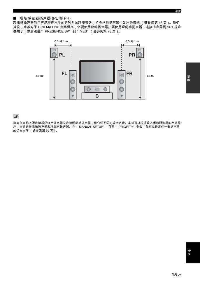
连接准
备中
文
现场感左右扬声器 (PL 和 PR)现场感扬声器利用声场程序产生的各种附加环境音效,扩充从前扬声器中发出的音响 (请参阅第 46 页)。我们建议,尤其对于 CINEMA DSP 声场程序,您要使用临场扬声器。要使用现场感扬声器,连接扬声器到 SP1 扬声器端子,然后设置 “ PRESENCE SP” 到 “ YES” (请参阅第 78 页)。
您能在本机上既连接后环绕声扬声器又连接现场感扬声器,但它们不同时输出声音。本机可以根据输入源和所选择的声场程序,自动切换临场扬声器和环绕声扬声器。在 “ MANUAL SETUP” ,使用 “ PRIORITY” 参数,您可以设定任一套扬声器的优先次序 (请参阅第 79 页)。
注
FR
PRPL
C
FL 1.8 m
0.5 到 1 m 0.5 到 1 m
1.8 m
15 Zh
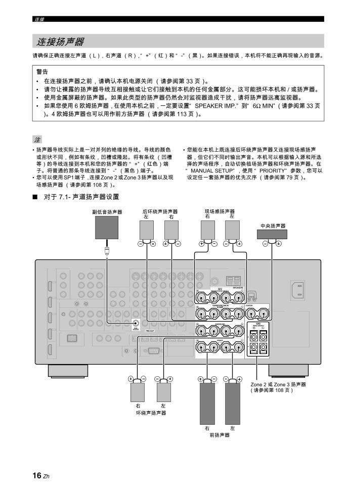
连接
请确保正确连接左声道 (L),右声道 (R),“ +” (红)和 “ -” (黑)。如果连接错误,本机将不能正确再现输入的音源。
• 扬声器导线实际上是一对并列的绝缘的导线。导线的颜色或形状不同,例如有条纹,凹槽或隆起。将有条纹 (凹槽等)的导线连接到本机和您的扬声器的 “ +” (红色)端子。将普通的那条导线连接到 “ -” (黑色)端子。
• 您可以使用SP1端子,连接Zone 2或Zone 3扬声器以及现场感扬声器 (请参阅第 108 页)。
• 您能在本机上既连接后环绕声扬声器又连接现场感扬声器,但它们不同时输出声音。本机可以根据输入源和所选择的声场程序,自动切换临场扬声器和环绕声扬声器。在“ MANUAL SETUP” ,使用 “ PRIORITY” 参数,您可以设定任一套扬声器的优先次序 (请参阅第 79 页)。
对于 7.1- 声道扬声器设置
连接扬声器
警告• 在连接扬声器之前,请确认本机电源关闭 (请参阅第 33 页)。• 请勿让裸露的扬声器导线互相接触或让它们接触到本机的任何金属部分。这可能损坏本机和 / 或扬声器。• 使用金属屏蔽的扬声器。如果此类型的扬声器仍然会对监视器造成干扰,请将扬声器远离监视器。• 如果您使用 6 欧姆扬声器,在使用本机之前,一定要设置“ SPEAKER IMP.” 到“ 6Ω MIN” ( 请参阅第 33 页
)。4 欧姆扬声器也可以用作前方扬声器 (请参阅第 113 页)。
注
SPEAKERS
CENTERBI-AMP
SURROUND BACK/
PRESENCE/ZONE 2/ZONE 3SP1
FRONT
SURROUNDZONE 2/ZONE 3
SINGLE
SP2
PRE OUT
SUBWOOFER
+
+ +
R L
R L
+ + +R L
+ +R L
+ +R L
前扬声器
环绕声扬声器
现场感扬声器副低音扬声器右 左左
中央扬声器
后环绕声扬声器右
左
左右
右
Zone 2 或 Zone 3 扬声器 ( 请参阅第 108 页 )
16 Zh

连接准
备中
文
对于 6.1- 声道扬声器设置
对于 5.1- 声道扬声器设置
后环绕声扬声器
SPEAKERS
CENTERBI-AMP
SURROUND BACK/
PRESENCE/ZONE 2/ZONE 3SP1
FRONT
SURROUNDZONE 2/ZONE 3
SINGLE
SP2
PRE OUT
SUBWOOFER
+
+ +
R L
R L
+ + +R L
+ +R L
+ +R L
前扬声器
环绕声扬声器
现场感扬声器 ( 请参阅第 15 和 16)
左
左右
右
SPEAKERS
CENTERBI-AMP
SURROUND BACK/
PRESENCE/ZONE 2/ZONE 3SP1
FRONT
SURROUNDZONE 2/ZONE 3
SINGLE
SP2
PRE OUT
SUBWOOFER
+
+ +
R L
R L
+ + +R L
+ +R L
+ +R L
副低音扬声器
中央扬声器
Zone 2 或 Zone 3 扬声器( 请参阅第 108 页 )
现场感扬声器 ( 请参阅第 15 和 16 页 )
环绕声扬声器左右
SPEAKERS
CENTERBI-AMP
SURROUND BACK/
PRESENCE/ZONE 2/ZONE 3SP1
FRONT
SURROUNDZONE 2/ZONE 3
SINGLE
SP2
PRE OUT
SUBWOOFER
+
+ +
R L
R L
+ + +R L
+ +R L
+ +R L
前扬声器
环绕声扬声器
副低音扬声器
中央扬声器
左
左右
右
Zone 2 或 Zone 3 扬声器( 请参阅第 108 页 )
用于双重放大连接的前扬声器( 请参阅第 19 页 ) 现场感扬声器
( 请参阅第 15 和 16 页 )
17 Zh

连接
连接扬声器缆线
1 从各个扬声器缆线端部剥去大约 10 mm 的绝缘皮,然后拧紧裸露的导线以防短路。
2 使用附带的扬声器端子旋钳松开旋钮。
3 将一条裸露的电线插入每个端子旁的孔中。
4 使用附带的扬声器端子旋钳旋紧旋钮,以紧固电线。
5 当不使用时,将扬声器端子旋钳吊挂到本机后面板上的 WRENCH HOLDER。
连接到 SP2 扬声器端子连接 Zone 2 或 Zone 3 扬声器到这些端子 (请参阅第 108页)。
1 打开舌片。
2 将裸露的电线插入该端子的孔中。
3 闭合舌片以固定电线。
10 mm
扬声器端子旋钳
红色: 正极 (+)黑色: 负极 (-)
红色: 正极 (+)黑色: 负极 (-)
18 Zh

连接准
备中
文
连接香蕉型插头( 英国,欧洲,亚洲和韩国型号除外 )
1 使用附带的扬声器端子旋钳拧紧旋钮。
2 将香蕉形插头插入相应的端子的端部。
y您也可以在 SP2 扬声器端子上使用香蕉插头。打开舌片,然后将香蕉插头插入该端子的孔中。连接香蕉插头后,不要闭合该舌片。
使用双重放大连接
本机允许您对于一个扬声器系统进行双重放大连接。检查您的扬声器系统是否支持双重放大连接。要进行双重放大连接,如下所示,使用 FRONT 和SURROUND BACK/BI-AMP 扬声器端子。要激活双重放大连接,在 “ ADVANCED SETUP” 将 “ BI-AMP” 设置到“ ON” (请参阅第 116 页)。
当您对扬声器进行常规连接时,请确认短接棒妥当嵌入扬声器端子。有关详情请参阅扬声器的使用说明书。
红色: 正极 (+)黑色: 负极 (-)
扬声器端子旋钳
香蕉形插头
警告去掉扬声器的短接棒或桥,分离 LPF (低音通过过滤器)和 HPF (高音通过过滤器)分频。
注
BI-AMPSURROUND BACK/
FRONT
SINGLE
+ +
++
R L
SURROUND+ +R
R
L
L
本机
左右前扬声器
19 Zh

连接
音频插孔本机有三种类型的音频插孔。连接基于您的其他装置上可用的音频插孔。
AUDIO 插孔用于普通的模拟音频信号的传输,使用左右模拟音频缆线。连接红色插头到右边的插孔,白色插头到左边的插孔。
DIGITAL COAXIAL 插孔用于通过数码同轴缆线传送的数码音频信号。
DIGITAL OPTICAL 插孔用于通过数码光学缆线传送的数码音频信号。
您能使用数码插孔来输入 PCM,Dolby Digital 和 DTS 比特流。当您连接组件机到 COAXIAL 和 OPTICAL 插孔时,从COAXIAL 插孔的输入信号拥有优先权。所有数码输入插孔都兼容 大 96-kHz 取样的数码信号。
视频插孔本机有三种类型的视频插孔。连接本机视频输入插孔到输入源装置的视频输出插孔,以便同时切换音频和视频源。连接基于您的视频监视器上可用的输入插孔。
VIDEO 插孔用于通过复合视频缆线传送普通的复合视频信号。
S VIDEO 插孔用于 S 视频信号,其亮度 (Y) 和色度 (C) 视频信号被分离,通过独立的 S 视频缆线传送。
COMPONENT VIDEO 插孔用于分量视频信号,其亮度 (Y) 和色度 (PB, PR) 视频信号被分离,通过独立的分量视频缆线传送。
y本机装备有视频转换功能。有关详情请参阅第 23 和 89 页。
插孔和缆线插头的有关信息
注
COAXIAL
DIGITALAUDIO
OPTICAL
DIGITALRL
CORL
左右模拟音频缆线插头
光学数码音频缆线插头
同轴数码音频缆线插头
音频插孔和缆线插头
( 红色 )( 白色 ) ( 橘红色 )
VIDEO S VIDEOCOMPONENT VIDEO
Y R PB P
PBY PRSV
复合视频缆线插头
S 视频缆线插头 分量视频缆线插头
视频插孔和缆线插头
( 黄色 ) ( 绿色 ) ( 蓝色 ) ( 红色 )
20 Zh

连接准
备中
文
本机具有 4 个 HDMI 输入插孔和 1 个 HDMI 输出插孔,用于数码音频和视频信号的输入 / 输出。将本机的 HDMI IN 1, HDMI IN 2, HDMI IN 3 或 HDMI IN 4 插孔连接到其他的 HDMI 装置 (例如 DVD 播放机)的 HDMI 输出插孔。连接本机的 HDMI OUT 插孔到其他的 HDMI 装置 (比如电视机和投影仪)的 HDMI 输入插孔。通过选择的输入源的 HDMI IN 插孔输入的视频或音频信号通过本机的 HDMI OUT 插孔输出。
您可以检查有关 HDMI 连接的潜在问题 (请参阅第 44 页)。
HDMI 插孔和缆线插头
y• 我们建议使用具有HDMI标记的,小于5 m的HDMI的缆线。• 使用转换缆线 (HDMI 插孔 ↔ DVI-D 插孔 ) 连接本机到其他
DVI 装置。
• 当数据正在传输时,不要从本机拆掉或连接缆线,或者关闭连接在本机的 HDMI OUT 插孔的 HDMI 装置的电源。这样做可能中断播放或导致噪音。
• 即使当 “ SUPPORT AUDIO” 被设置为 “ OTHER” ( 请参阅第 85 页 ) 时,HDMI OUT 插孔也仅输出来自 HDMI输入插孔的音频信号。
• 如果您关闭了通过 DVI 连接而连接到 HDMI OUT 插孔的视频监视器的电源,本机也许不能建立到该装置的连接。
• 通过组合视频,S 视频和分量视频插孔输入的模拟视频信号可以被数码内部转换,通过 HDMI OUT 插孔输出。在“ MANUAL SETUP” (请参阅第 89 页),设置 “ VIDEO CONV.” 到 “ ON” ,以激活该性能。
HDMI 输入插孔的默认输入分配
HDMITM 的有关信息
本机的 HDMI 接口基于以下设计标准:• HDMI 版本 1.3a( 高分辨率多媒体界面规格版本 1.3a), 获 HDMI Licensing, LLC. 授权。• HDCP ( 高带宽数码内容保护系统 ),获 Digital Content Protection, LLC. 授权。
注
注
HDMI
HDMI 缆线插头
HDMI 输入插孔 分配的输入源
IN1 BD/HD DVD
IN2 DVD
IN3 DTV/CBL
IN4 DVR
21 Zh
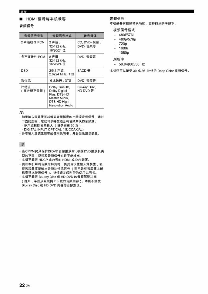
连接
HDMI 信号与本机兼容音频信号
y• 如果输入源装置可以解码音频解说的比特流音频信号,通过
下面的连接,您就可以播放混合有音频解说的音频源 :- 多声道模拟音频输入 (请参阅第 30 页)- DIGITAL INPUT OPTICAL ( 或 COAXIAL)
• 参考输入源装置附带的使用说明书,并妥当设置该装置。
• 当CPPM拷贝保护的DVD音频播放时,根据DVD播放机类型的不同,视频和音频信号也许不能输出。
• 本机不兼容 HDCP 非兼容的 HDMI 或 DVI 装置。• 要在本机解码音频比特流时,要妥当设置输入源装置,使
得该装置直接输出音频比特流信号 (而不是在该装置上解码音频比特流信号)。详情请参阅附带的使用说明书。
• 本机不兼容 Blu-ray Disc 或 HD DVD 的音频解说功能(例如,某些从互联网上下载的音频内容)。本机不播放Blu-ray Disc 或 HD DVD 内容的音频解说。
视频信号本机装备有视频转换功能,支持的分辨率如下:
视频信号格式- 480i/576i- 480p/576p- 720p- 1080i- 1080p
刷新率- 59.94(60)/50 Hz
本机还可以接受 30 或 36- 比特的 Deep Color 视频信号。
音频信号类型 音频信号格式 兼容媒体
2 声道线性 PCM 2 声道 , 32-192 kHz, 16/20/24 位
CD, DVD- 视频 , DVD- 音频等
多声道线性 PCM 8 声道 , 32-192 kHz, 16/20/24 位
DVD- 音频等
DSD 2/5.1 声道 , 2.8224 MHz, 1 位
SACD 等
数位流 杜比数码 , DTS DVD- 音频等
比特流(高分辨率音频)
Dolby TrueHD, Dolby Digital Plus, DTS-HD Master Audio, DTS-HD High Resolution Audio
Blu-ray Disc,HD DVD 等
注
22 Zh

连接准
备中
文
音频信号流向
• 当 “ SUPPORT AUDIO” 设置到 “ OTHER” (请参阅第85 页)时,通过 HDMI 插孔之一输入的 2- 声道以及多声道 PCM, Dolby Digital 和 DTS 信号,只能通过 HDMI OUT插孔输出。
• 以下类型的音频信号只能通过 HDMI 输入插孔输入:- DSD- Dolby TrueHD- Dolby Digital Plus- DTS-HD Master Audio- DTS-HD High Resolution Audio
视频信号流向
y使用 “ VIDEO SET” 参数,您可以进行视频信号的非隔行化或转换其分辨率。有关详情请参阅第 89 页。
• 当模拟视频信号通过 COMPONENT VIDEO, S VIDEO 和 VIDEO 插孔输入时,输入信号的优先顺序如下: 1. COMPONENT VIDEO2. S VIDEO3. VIDEO
• 从 HDMI 输入插孔输入的数码视频信号不能输出到模拟视频插孔。
• 模拟分量视频信号 (仅限于分辨率为 480i (NTSC)/576i(PAL))可以被转换到 S 视频或复合视频信号,并通过 VIDEO 或 S VIDEO MONITOR OUT 插孔输出。
• 具有1080p分辨率的视频信号仅通过本机的COMPONENT VIDEO MONITOR OUT 插孔输出。
• OSD信号不通过DVR OUT和VCR OUT插孔输出及录制。
音频和视频信号流向
注
DIGITAL AUDIO(OPTICAL)
DIGITAL AUDIO(COAXIAL)
HDMI
AUDIO
输出输入
模拟输出
数码输出
注
S VIDEO
VIDEO
COMPONENTVIDEO
HDMI
通过
输出输入
视频转换 ON( 请参阅第 89 页 )
23 Zh

连接
将您的电视机 (或投影仪)连接到本机的 HDMI OUT 插孔,COMPONENT VIDEO MONITOR OUT 插孔,S VIDEO MONITOR OUT 插孔或 VIDEO MONITOR OUT 插孔。
y您可以选择在本机播放 HDMI 音频信号,还是在连接在本机的后面板的 HDMI OUT 插孔上的其他 HDMI 装置上播放。使用 “ SOUND MENU” 的 “ SUPPORT AUDIO” 参数,选择该装置播放 HDMI 音频信号 (请参阅第 85 页)。
• 通过 DVI 连接到本机的某些视频监视器,如果它们在待机模式,就不能辨认正在输入的 HDMI 音频 / 视频信号。在此情形下,HDMI 指示器不规则地闪烁。
• 设置 “ OPTION MENU” 的 “ VIDEO CONV.” 为“ ON” (请参阅第 89 页)以显示短信息和声场参数。
• 根据输入视频信号格式和在 “ DISPLAY SET” 中参数的设置 (请参阅第 88 页),“ SET MENU” 和声场参数显示以灰色背景出现。
• 如果所连接的视频监视器兼容自动音频和视频同步特性(自动口形同步特性),本机可自动进行音频和视频的调速(请参阅第 84 页)。连接视频监视器到本机的 HDMI OUT 插孔以使用此特性。
连接电视机或投影仪
确认本机和其他装置没有连接到墙壁上的交流电源插座。
注
VIDEO
S VIDEO
MONITOR OUTVIDEOHDMI COMPONENT VIDEO
MONITOR OUT
Y
PR
PB
OUT
PRPB V SY
电视机 (或投影仪)
视频输入分量视频输入
S 视频输入HDMI 输入
指示推荐的连接
指示可选的连接
24 Zh
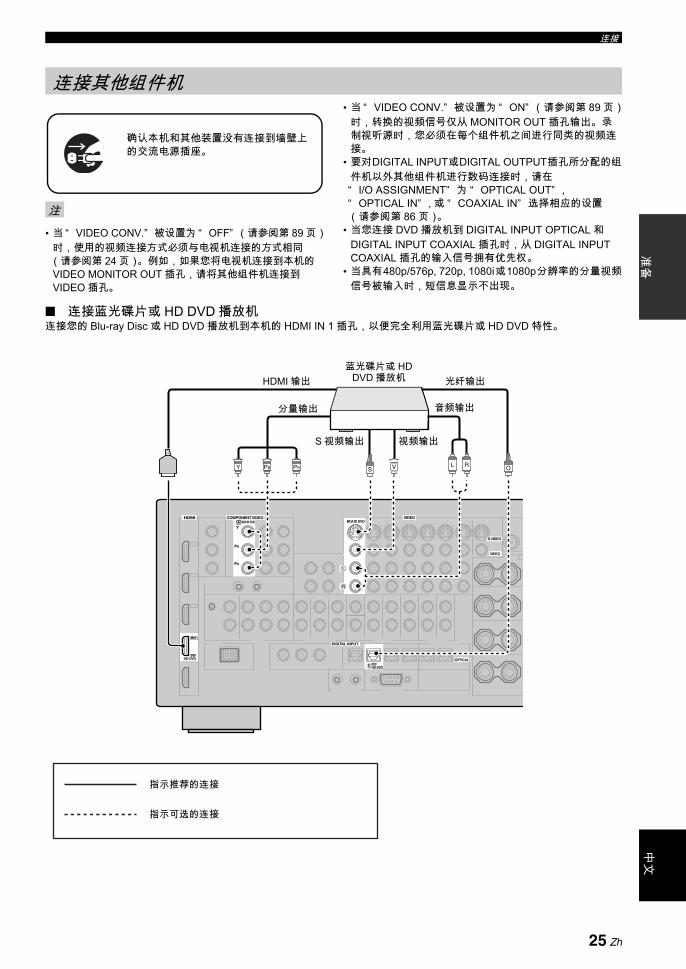
连接准
备中
文
• 当 “ VIDEO CONV.” 被设置为 “ OFF” (请参阅第 89 页)时,使用的视频连接方式必须与电视机连接的方式相同(请参阅第 24 页)。例如,如果您将电视机连接到本机的VIDEO MONITOR OUT 插孔,请将其他组件机连接到VIDEO 插孔。
• 当 “ VIDEO CONV.” 被设置为 “ ON” (请参阅第 89 页)时,转换的视频信号仅从 MONITOR OUT 插孔输出。录制视听源时,您必须在每个组件机之间进行同类的视频连接。
• 要对DIGITAL INPUT或DIGITAL OUTPUT插孔所分配的组件机以外其他组件机进行数码连接时,请在“ I/O ASSIGNMENT” 为 “ OPTICAL OUT” ,“ OPTICAL IN” , 或 “ COAXIAL IN” 选择相应的设置(请参阅第 86 页)。
• 当您连接 DVD 播放机到 DIGITAL INPUT OPTICAL 和DIGITAL INPUT COAXIAL 插孔时,从 DIGITAL INPUT COAXIAL 插孔的输入信号拥有优先权。
• 当具有480p/576p, 720p, 1080i或1080p分辨率的分量视频信号被输入时,短信息显示不出现。
连接蓝光碟片或 HD DVD 播放机连接您的 Blu-ray Disc 或 HD DVD 播放机到本机的 HDMI IN 1 插孔,以便完全利用蓝光碟片或 HD DVD 特性。
连接其他组件机
注
确认本机和其他装置没有连接到墙壁上的交流电源插座。
VIDEO
S VIDEO
VIDEOHDMI COMPONENT VIDEO
DIGITAL INPUT
BD/HD DVD
OPTICAL
5
BD/HD DVDBD/HD DVD
Y
PR
PB
BD/HD DVD
A
R
L
IN1
L R OVSPRPBY
蓝光碟片或 HD DVD 播放机HDMI 输出
分量输出
S 视频输出 视频输出
光纤输出
音频输出
指示推荐的连接
指示可选的连接
25 Zh

连接
连接 DVD 播放机
VIDEO
S VIDEO
VIDEOHDMI COMPONENT VIDEO
DIGITAL INPUT
DVD
COAXIAL
DVD
OPTICAL
62
DVDDVD
Y
PR
PB
DVD
B
R
L
IN2
C OVSL RPRPBY
DVD 播放机HDMI 输出同轴输出
分量输出
S 视频输出 视频输出
光纤输出
音频输出
指示推荐的连接
指示可选的连接
26 Zh

连接准
备中
文
连接 DVD 刻录机,PVR 或 VCR
* 当您连接了另外的 VCR 到本机时,像连接 DVR 端子那样将它连接到 VCR 端子 (S VIDEO IN, VIDEO IN, AUDIO IN, S VIDEO OUT, VIDEO OUT 和 AUDIO OUT 插孔 ) ,仅 DIGITAL INPUT (COAXIAL) 插孔除外。
连接置顶盒
注
VIDEO
S VIDEO
VIDEOHDMI
DIGITAL INPUT
DVR
COAXIAL
3
VCRDVR OUT OUTININ
DVR
R
L
IN4
DVR OUTIN
RL R LV VS SC
DVD 刻录机,PVR 或 VCR
同轴
输出
S视
频输
出
视频
输出
音频
输入
视频
输入
S视
频输
入
音频
输出
HD
MI输
出
*
VIDEO
S VIDEO
VIDEOHDMI COMPONENT VIDEO
DIGITAL INPUT
DTV/CBL
OPTICAL
7
DTV/CBLDTV/CBL
Y
PR
PB
DTV/CBL
C
R
L
IN3
OV L RSPRPBY
卫星接收机,有线电视接收机或 HDTV 解码器HDMI 输出
分量输出
视频
输出
音频
输出
S视
频输
出
光纤输出
27 Zh
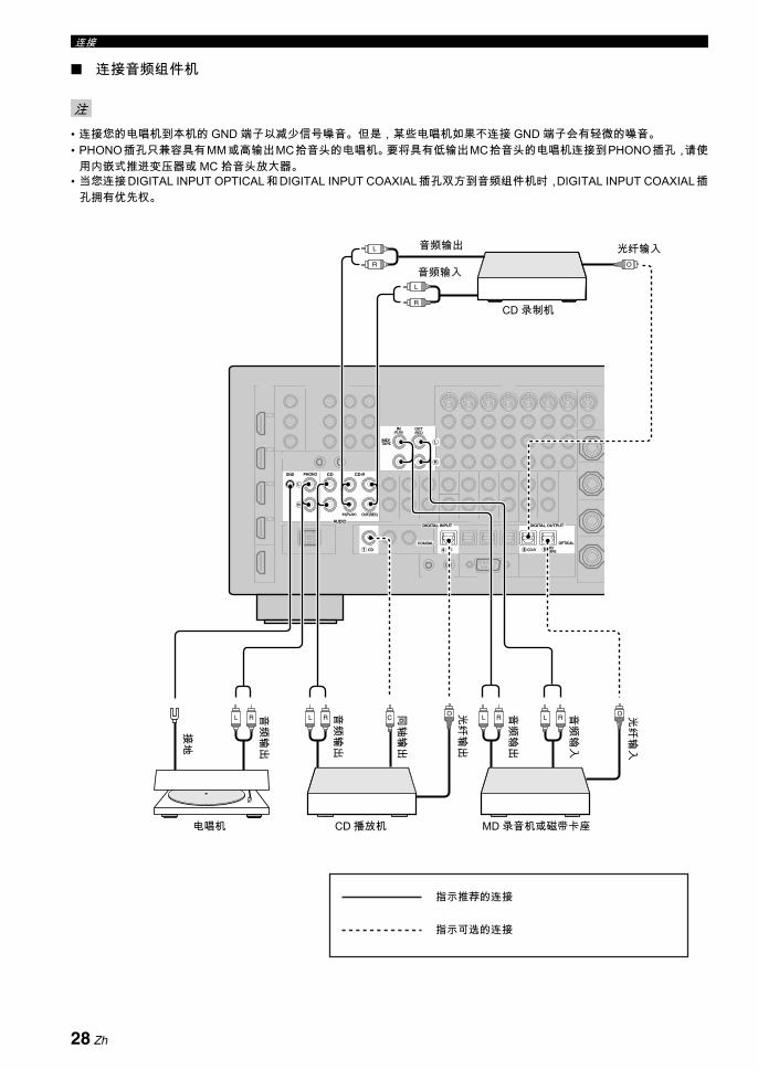
连接
连接音频组件机
• 连接您的电唱机到本机的 GND 端子以减少信号噪音。但是,某些电唱机如果不连接 GND 端子会有轻微的噪音。• PHONO插孔只兼容具有MM或高输出MC拾音头的电唱机。要将具有低输出MC拾音头的电唱机连接到PHONO插孔,请使
用内嵌式推进变压器或 MC 拾音头放大器。• 当您连接DIGITAL INPUT OPTICAL和DIGITAL INPUT COAXIAL插孔双方到音频组件机时,DIGITAL INPUT COAXIAL插
孔拥有优先权。
注
PHONOGND CD
IN(PLAY) OUT(REC)
CD-R
AUDIODIGITAL INPUT DIGITAL OUTPUT
CD
COAXIAL
CD MD/ TAPECD-R
OPTICAL
9841
TAPEMD/
(REC)(PLAY)IN OUT
R
L
R
L
L RL RL RL R
L
R
L
R
COO
O
CD 录制机
电唱机 CD 播放机 MD 录音机或磁带卡座
音频输入
光纤输入音频输出
光纤
输出
音频
输入
音频
输出
光纤
输入
接地
音频
输出
同轴
输出
音频
输出
指示推荐的连接
指示可选的连接
28 Zh
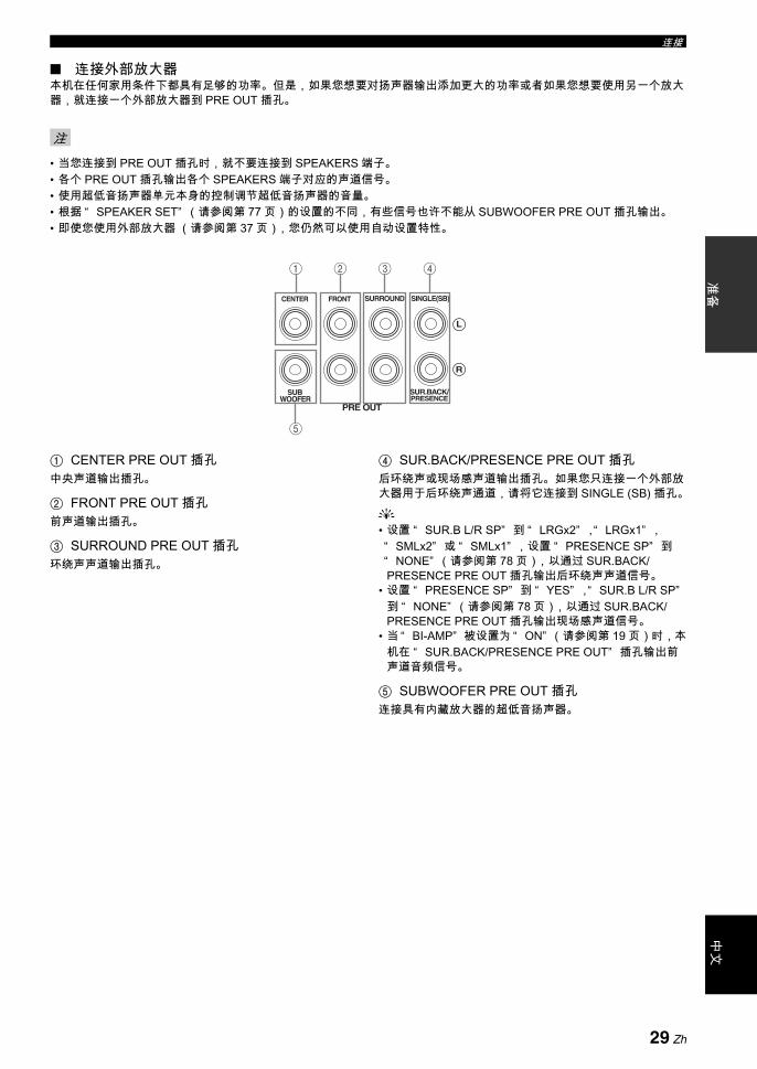
连接准
备中
文
连接外部放大器本机在任何家用条件下都具有足够的功率。但是,如果您想要对扬声器输出添加更大的功率或者如果您想要使用另一个放大器,就连接一个外部放大器到 PRE OUT 插孔。
• 当您连接到 PRE OUT 插孔时,就不要连接到 SPEAKERS 端子。• 各个 PRE OUT 插孔输出各个 SPEAKERS 端子对应的声道信号。• 使用超低音扬声器单元本身的控制调节超低音扬声器的音量。• 根据 “ SPEAKER SET” (请参阅第 77 页)的设置的不同,有些信号也许不能从 SUBWOOFER PRE OUT 插孔输出。• 即使您使用外部放大器 (请参阅第 37 页),您仍然可以使用自动设置特性。
1 CENTER PRE OUT 插孔中央声道输出插孔。
2 FRONT PRE OUT 插孔前声道输出插孔。
3 SURROUND PRE OUT 插孔环绕声声道输出插孔。
4 SUR.BACK/PRESENCE PRE OUT 插孔后环绕声或现场感声道输出插孔。如果您只连接一个外部放大器用于后环绕声通道,请将它连接到 SINGLE (SB) 插孔。
y• 设置 “ SUR.B L/R SP” 到 “ LRGx2” ,“ LRGx1” ,“ SMLx2” 或 “ SMLx1” ,设置 “ PRESENCE SP” 到“ NONE” (请参阅第 78 页),以通过 SUR.BACK/PRESENCE PRE OUT 插孔输出后环绕声声道信号。
• 设置 “ PRESENCE SP” 到 “ YES” ,“ SUR.B L/R SP”到 “ NONE” (请参阅第 78 页),以通过 SUR.BACK/PRESENCE PRE OUT 插孔输出现场感声道信号。
• 当 “ BI-AMP” 被设置为 “ ON” (请参阅第 19 页)时,本机在 “ SUR.BACK/PRESENCE PRE OUT” 插孔输出前声道音频信号。
5 SUBWOOFER PRE OUT 插孔连接具有内藏放大器的超低音扬声器。
注
PRE OUT
SUBWOOFER
CENTER FRONT SURROUND
PRESENCESUR.BACK/
SINGLE(SB)
R
L
5
4321
29 Zh

连接
连接多格式播放机或外部解码器本机配备有 6 个额外的输入插孔(左和右 FRONT,CENTER,左和右 SURROUND 以及 SUBWOOFER),用于来自多格式播放机,外部解码器,声音处理器或前置放大器的分散的多声道输入。在 “ MULTI CH” ,如果您设置 “ INPUT CH” 到 “ 8CH” ( 请参阅第 87 页 ), 为了输入 8 声道信号,您可以一起使用在“ MULTI CH” 当作 “ FRONT” 指定的输入插孔和 MULTI CH INPUT 插孔。连接您的多格式播放机或外部解码器上的输出插孔到 MULTI CH INPUT 插孔。请确保将左输出和右输出匹配前声道和环绕声声道的左和右输入插孔。
• 当您选择连接到 MULTI CH INPUT 的组件机作为输入音源时 ( 请参阅第 43 页 ),本机自动关闭数码声场处理器,您不能选择声场程序。
• 本机不会将信号输入重新指向 MULTI CH INPUT 插孔来适应缺少的扬声器。我们建议您在使用此特性之前,连接至少 5.1 声道的扬声器系统。
• 当连接到本机 MULTI CH INPUT 插孔的组件机被选择为输入源时,仅有通过 MULTI CH INPUT FRONT 插孔输入的信号从连接的耳机输出。
用于 6 声道输入 用于 8 声道输入
* 模拟音频输入插孔在 “ MULTI CH” (请参阅第 85 页)配置为 “ FRONT” 。
注
MULTI CH INPUT
SUBWOOFER
CENTER FRONT(6CH) SURROUND
SB(8CH)
R
L
L R L R
超低
音扬
声器
输出
多格式播放机 / 外部解码器
中央
输出
环绕
声输
出
前输
出
注
MULTI CH INPUT
SUBWOOFER
SUB
CENTER FRONT(6CH) SURROUND
SB(8CH)
TAPEMD/
( C)( )
R
L
R
L
L R L RL R
多格式播放机 / 外部解码器
前输
出
超低
音扬
声器
输出
中央
输出
后环
绕声
扬声
器输
出
环绕
声输
出
*
30 Zh

连接准
备中
文
连接 Yamaha iPod 多用平台本机在后部面板上装备有 DOCK 端子,这可以使得您连接Yamaha iPod 多用平台 (比如 YDS-10,另售),在此平台上您可以驳接 iPod 并使用附带的遥控器操作 iPod。使用专用缆线,连接 Yamaha iPod 多用平台 (比如 YDS-10,另售)到本机后部面板上的 DOCK 端子。
使用 REMOTE IN/OUT 插孔当装置是 Yamaha 产品 , 且具有遥控信号传输功能 , 使用下述的单声道模拟迷你缆线 , 连接 REMOTE IN 和 REMOTE OUT 插孔到遥控输入和输出插孔。有关此特性的详情,请参阅第 108 页。
使用前面板上的 VIDEO AUX 插孔,连接游戏机或摄像机到本机。
从后部面板上的 DOCK 插孔输入的音频信号优先于从VIDEO AUX 插孔输入的信号。
DOCK
Yamaha iPod 多用平台(比如 YDS-10,另售)
REMOTE IN OUT
Yamaha 组件机(CD 或 DVD 播放机
等 )
遥控器输入遥控器输出
红外线信号接收机或 Yamaha 装置
在前面板上使用 VIDEO AUX 插孔
警告在进行连接之前,请务必减低本机和其他组件机的音量。
注
MASTER
PURE DIRECT
VOLUME
MAIN ZONE
INPUT
OFFON
SLEEP
ZONE ON/OFF ZONE CONTROLS
MULTI ZONE
MICOPTIMIZER
EFFECT
PROGRAM
YPAO
ZONE 3
RL OPTICAL
ZONE 2
AUDIO
VIDEO AUX
SILENT CINEMA S VIDEO VIDEO
PHONES
MODETUNING
PRESET/TUNING
EDIT
FM/AMTUNINGPRESET/
MAN'L/AUTO FMMEMORY
STRAIGHT
CONTROLSELECTAUDIO TONE
A/B/C/D/E
ON/OFF
RL OPTICALAUDIOS VIDEO VIDEO
OVS L R
游戏机或视频摄像机
S视
频输
出
视频
输出
音频
输出
光学
输出
31 Zh
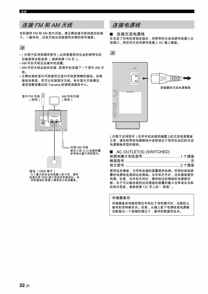
连接
本机提供 FM 和 AM 室内天线。请正确连接天线到指定的端子。一般来说,这些天线应该能提供足够的信号强度。
•(仅限于亚洲和通用型号)必须根据您所在地的频率空间切换频率步距选择 (请参阅第 116 页)。
• AM 环形天线应远离本机放置。• AM 环形天线应始终连接,即使本机连接了一个室外 AM 天
线。• 正确安装的室外天线提供比室内天线更清晰的接收。如果
接收效果差,您可以安装室外天线。有关室外天线情况,请咨询离您 近的 Yamaha 经销商或服务中心。
连接交流电源线在完成了所有的其他连接后,将附带的交流电源导线插入交流插口,然后将交流电源导线插入 AC 墙上插座。
(仅限于亚洲型号)在将本机连接到墙壁上的交流电源插座之前,请在附带的电源缆线中选择适合于您所在地区的交流电源插座类型的缆线。
AC OUTLET(S) (SWITCHED)英国和澳大利亚型号 .....................................1 个插座韩国型号 .................................................................无其它型号 .......................................................2 个插座使用这些插座,为所有连接的装置提供电源。将您的其他装置的电源线连接到这些插座。当本机打开时,这些插座提供电源。但是,当本机关闭时,提供给这些插座的电源被切断。关于可以被连接到这些插座的装置的 大功率或总功耗的有关信息,请参阅第 131 页上的 “ 规格” 。
连接 FM 和 AM 天线
注
ANTENNA
FM GND AM75Ω UNBAL.
室内 FM 天线(附带)
接地 (GND 端子)为了 大的安全性和 小的干扰,请将
连接天线 GND 端子到良好的接地处。良好的接地处是插入潮湿泥土的金属条。
AM 环形天线(附带)
外部 AM 天线使用 5 到 10 m 的塑料覆皮导线从窗户伸到室外。
连接电源线
注
存储器备份存储器备份电路即使在本机处于待机模式时,也能防止储存的资料被丢失。但是,从墙上拔下电源线或电源被切断超过一个星期的情况下,储存的数据将丢失。
AC OUTLETS
AC IN
到墙壁的交流电源插座
32 Zh

连接准
备中
文
1 确认本机被关闭。
2 按下并保持前面板上的OSTRAIGHT 按钮,然后向内按下AMASTER ON/OFF 到 ON 位置,打开本机。本机打开,高级设置菜单出现在前面板显示器上。
3 旋转NPROGRAM 选择器,选择 “ SPEAKER IMP.” 。
4 反复按OSTRAIGHT 选择 “ 6Ω MIN” 。
5 按下AMASTER ON/OFF,向外释放到 OFF 位置,以保存新设置并关闭本机。
您的设置在下次打开本机时生效。
打开本机
向内按下前面板上的AMASTER ON/OFF 按钮到ON 位置,打开本机。当您按下AMASTER ON/OFF 打开本机时,主区域打开。
y当您打开本机时,在本机能够再现声音之前将有几秒钟延迟。
关闭本机
再次按下前面板上的AMASTER ON/OFF 按钮,向外释放到 OFF 位置,关闭本机。
• 只有当向内按下AMASTER ON/OFF 按钮到 ON 位置时,前面板上的BMAIN ZONE ON/OFF 以及遥控器上的8POWER 和 7STANDBY 可以操作。
• 一般地,我们建议关闭本机时,使其处于待机状态。
将主区域设置为待机模式
按下BMAIN ZONE ON/OFF(或 7STANDBY)将主区域设置为待机模式。在待机模式,本机消耗少量电力,以接收来自遥控器的红外线信号。
从待机模式打开主区域
按下BMAIN ZONE ON/OFF ( 或 8POWER),打开主区域。
y• 当您打开本机时,在本机能够再现声音之前将有几秒钟延
迟。• 只有当向内按下AMASTER ON/OFF 按钮到 ON 位置时,
这些按钮才能操作。
设置扬声器阻抗
警告如果您使用 6 欧姆扬声器 , 在使用本机之前,一定要设置 “ SPEAKER IMP.” 到 “ 6Ω MIN” 如下。4 欧姆扬声器也可以用作前方扬声器。
注
EFFECT
STRAIGHT
MASTER
在按住的同时
打开或关闭本机
注
如果出现问题 ...• 首先,关闭本机,然后再开启。• 如果问题依然存在,初始化本机的参数。 有关
详情请参阅第 124 页。
33 Zh

连接
1 HDMI 指示器当选择的输入源信号在 HDMI 输入插孔之一输入时点亮 ( 请参阅第 21 页 )。
2 DOCK 指示器当您在连接到本机的 iPod 端子的 Yamaha iPod 多用平台 (比如 YDS-10,另售 ) 上驳接 DOCK 时点亮 ( 请参阅第 31 页)。
3 电池充电指示器当本机在待机模式为驳接在本机的 iPod 充电时点亮 (请参阅第 61 页)。
4 输入源指示器当前选择的输入源对应的光标点亮。
5 MUTE 指示器和 VOLUME 水平指示器• 指示当前的音量水平。• 当 MUTE 功能开启时,MUTE 指示器闪烁(请参阅
第 44 页)。
6 多信息显示当调节或改变设置时,显示当前声场程序名称和其它信息。
7 96/24 指示器当 DTS 96/24 信号被输入到本机时点亮。
8 输入声道和扬声器指示器
输入声道指示器• 指示当前输入数码信号的声道组件机。• 当本机在自动设置过程中(请参阅第37页)或处
于 “ SPEAKER LEVEL” ( 请参阅第 79 页 ) 的扬声器水平设置过程中 ,根据扬声器的设置点亮或闪烁。
现场感扬声器指示器当本机在自动设置过程中 ( 请参阅第 37 页 ) 或处于“ SPEAKER LEVEL” ( 请参阅第 79 页 ) 的扬声器水平设置过程中,根据 “ SPEAKER SET” 的“ PRESENCE SP” 的设置 (请参阅第 78 页)点亮或闪烁。
y您可以对现场感和后环绕声扬声器用运行 “ AUTO SETUP” (请参阅第 37 页)的方式进行自动设置或对“ SPEAKER SET” 的 “ PRESENCE SP” (请参阅第78 页)和 “ SUR.B L/R SP” (请参阅第 78 页)进行手动调节设置。
前面板显示器
MUTEVOLUMEdB
LL C RSL SB SR
DSDPCM
96/24
TUNED STEREOAUTO MEMORY
PSZONE2ZONE3
SLEEPPTY HOLD
PTYRTCT
EON
CD-R CD PHONO MULTI CH TUNERMD/TAPEBD/HD DVDDVDDOCK
DVR DTV/CBLVCRV-AUX
MASTER AUDIO
MATRIX DISCRETESILENT
CINEMAYPAO ENHANCERVIRTUAL HiFi DSP
HD 9624
q DIGITAL PLUS
q TRUE HDq EXq PL x LFE
SBRSBL
TUNED STEREOAUTO MEMORY
PSZONE2ZONE3
SLEEPPTY HOLD
PTYRTCT
EONBA
0
9876
5431 2
有关详情请参阅第 35 页。
现场感扬声器指示器
输入声道指示器LL C RSL SB SRLFE
SBRSBL
34 Zh

连接准
备中
文
9 调谐器指示器当本机处于 FM 或 AM 调谐模式时点亮。
TUNED 指示器当本机调谐到一个电台时点亮 (请参阅第 54 页)。
STEREO 指示器当 AUTO 指示器点亮时,本机正在接收一个 FM 立体声广播的强信号时,点亮 (请参阅第 54 页)。
AUTO 指示器当本机处于自动调谐模式时点亮 (请参阅第 54 页)。
MEMORY 指示器闪烁以显示能储存一个电台 (请参阅第 55 页)。
0 ZONE2/ZONE3 指示器当 Zone 2 或 Zone 3 开启时点亮 ( 请参阅第 109 页 )。
A SLEEP 指示器当睡眠定时器开启时点亮 (请参阅第 45 页)。
B 无线电数据系统指示器 ( 仅限欧洲型号 )
PTY HOLD在 PTY SEEK 模式搜索无线电数据系统电台时点亮。
PS, PTY, RT 和 CT根据选择的无线电数据系统显示模式点亮。
EON当接收到 EON 数据服务时点亮。
C YPAO 指示器当您运行 “ AUTO SETUP” 时以及当在 “ AUTO SETUP”中设置的扬声器设置被使用且不进行任何更改时点亮 (请参阅第 37 页)。
D 输入信号信息指示器当本机再现 DSD (直接数据流数码)或 PCM (脉冲编码调制)数码音频信号时点亮。
E DSP 指示器当任何一个声场程序被选择时,相应的指示灯点亮。
CINEMA DSP 指示器当您选择了一个 CINEMA DSP 声场程序时点亮 (请参阅第 46 页)。
HiFi DSP 指示器当您选择了一个 HiFi DSP 声场程序时点亮 (请参阅第46 页)。
VIRTUAL 指示器当启用 Virtual CINEMA DSP 时点亮 (请参阅第 51页)。
F 声场指示器点亮以指示工作的声场 ( 请参阅第 46 页 )。
G ENHANCER 指示器当 Compressed Music Enhancer 模式开启时点亮 (请参阅第 50 页)。
H 耳机指示器当连接了耳机时点亮 (请参阅第 43 页)。
I SILENT CINEMA 指示器当连接了耳机和选择了一个声场程序时点亮 (请参阅第 51页)。
J 解码器指示器本机的任一解码器动作时相应的指示器点亮。
DSDPCM
MASTER AUDIO
MATRIX DISCRETE
SILENT CINEMA
YPAO ENHANCER
HD 9624
q DIGITAL PLUS
q TRUE HDq EXq PL x
VIRTUAL HiFi DSPC
D
EFGHI
J
35 Zh

连接
遥控器发射一道有方向性的红外线光束。在操作期间,请确保遥控器直接对准本机上的遥控器传感器。
显示窗口 (A)显示所选择的您可以控制的输入源名称。
红外线窗口 (P)输出红外线控制信号。将此窗口对准您想要操作的组件机。
传送指示器 (O)当遥控器在发送红外信号时闪烁。
操作模式选择器 (C)某些按钮的功能取决于操作模式选择器的位置。
AMP操作本机的放大器功能。
SOURCE操作用输入选择按钮选择的组件机 (请参阅第 98 页)。
TV操作分配到 DTV/CBL 或 PHONO 的电视机 ( 请参阅第97 页 )。
• 请勿水或其它液体洒在遥控器上。• 请勿跌落遥控器。• 请勿使遥控器处于或保存于下列环境中:
- 高湿度的地方,例如浴室附近- 高温度的地方,例如加热器或炉子附近- 温度极低的地方- 肮脏的地方
• 要为其他组件机设定遥控器代码,请参看请参阅第 99 页。
当您想要使用前面板门后的控制按钮时,请轻按面板的下部打开前部板门。在不使用这些控制按钮时,请保持面板门关闭。
使用遥控器
30 30大约 6 m
遥控器传感器
注
打开和关闭前面板门
要打开,请轻按面板的下部。
36 Zh

准备
中文
本机使用 YPAO (Yamaha Parametric Room Acoustic Optimizer) 技术,它可以帮您避免繁琐的听音环境的扬声器设置,并自动获得高准确度的音响调节。随机提供的优化器麦克风可以收集并分析您的实际听音环境中的扬声器产生的音响。
• 请注意,在 “ AUTO SETUP” 步骤中输出很响的测试音调是正常的。
• 要达到 佳效果,在 “ AUTO SETUP” 步骤进行时,请务必保持房间尽量安静。如果有太多环境噪音,结果可能不令人满意。如果有太多环境噪音,结果可能不令人满意。
• 当本机进行自动设置时,建议您离开房间。当你离开房间时要保持肃静。对于本机,要完成自动设置过程大约花费3 分钟。
y• 每个参数的初始设置以粗体表示。• 在进行操作之前,设置遥控器的操作模式选择器到CAMP。
自动设置的基本过程
1 开始 AUTO SETUP 操作之前,请务必检查下列要点。 扬声器被适当地连接。 耳机已经从本机拔下。 本机以及视频监视器打开。 连接的超低音扬声器打开,音量水平被设置为中
间 (或略低)。 连接的超低音扬声器的分频频率被设置为 大。 如果您使用外部放大器 (请参阅第 29 页),该放
大器被打开且设置妥当。 房间十分安静。
2 连接随机提供的优化器麦克风到前面板上的OPTIMIZER MIC 插孔。“ MIC ON” 和 “ View OSD Menu” 出现在前面板显示器中。
以下菜单屏幕出现在视频监视器上。
y您也可以使用前面板显示器上出现的系统菜单来完成“ AUTO SETUP” 。当您连接随机提供的优化器麦克风到前面板上的 OPTIMIZER MIC 插孔时,前面板显示器上出现以下显示。本说明书使用 OSD 插图说明“ AUTO SETUP” 步骤。
3 将优化器麦克风放置在您通常收听位置的平整的水平表面上,全方向麦克风头向上。
y推荐您使用一个三脚架 (等)以固定优化器麦克风,使得当您坐在收听位置时与您的耳朵所处高度相同。 您可以使用三脚架 (等)的固定螺钉将优化器麦克风固定到三脚架 (等)上。
为您的听音室优化扬声器设置
使用 AUTO SETUP
注
SLEEP
ZONE ON/OFF ZONE CONTROLS
MULTI ZONE
MICOPTIMIZER
EFFECT
PROGRAM
YPAO
ZONE 3
RL OPTICAL
ZONE 2
AUDIO
VIDEO AUX
SILENT CINEMA S VIDEO VIDEO
PHONES
MODETUNING
PRESET/TUNING
EDIT
FM/AMTUNINGPRESET/
MAN'L/AUTO FMMEMORY
STRAIGHT
CONTROLSELECTAUDIO TONE
A/B/C/D/E
全方向麦克风
[]/[]:[ENTER]:
[ p
AUTO SETUP
SETUP;;;;;;;;;AUTOWIRING;;;;;;;CHECKDISTANCE;;;;;CHECKSIZE;;;;;;;;;CHECKEQ;;;;;;;;;NATURALLEVEL;;;;;;;;CHECKSTART
UP/DOWNStart
.
A U T O S E T U P
E N T E R T O S T A R T
优化器麦克风
37 Zh
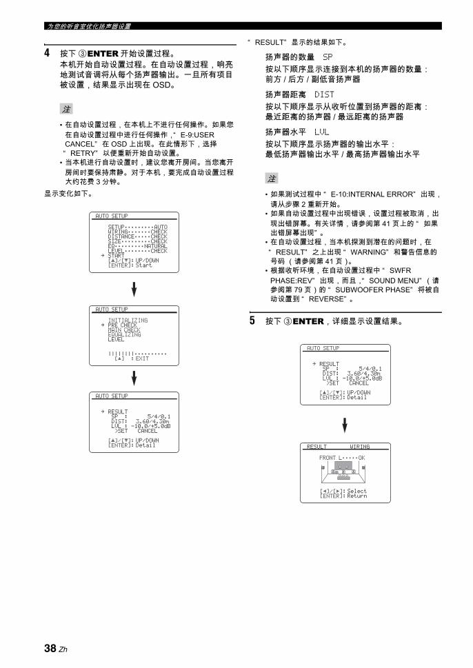
为您的听音室优化扬声器设置
4 按下 3ENTER 开始设置过程。本机开始自动设置过程。在自动设置过程,响亮地测试音调将从每个扬声器输出。一旦所有项目被设置,结果显示出现在 OSD。
• 在自动设置过程,在本机上不进行任何操作。如果您在自动设置过程中进行任何操作,“ E-9:USER CANCEL” 在 OSD 上出现。 在此情形下,选择“ RETRY” 以便重新开始自动设置。
• 当本机进行自动设置时,建议您离开房间。当您离开房间时要保持肃静。 对于本机,要完成自动设置过程大约花费 3 分钟。
显示变化如下。
“ RESULT” 显示的结果如下。
扬声器的数量 SP
按以下顺序显示连接到本机的扬声器的数量:前方 / 后方 / 副低音扬声器
扬声器距离 DIST
按以下顺序显示从收听位置到扬声器的距离:近距离的扬声器 / 远距离的扬声器
扬声器水平 LVL
按以下顺序显示扬声器的输出水平:低扬声器输出水平 / 高扬声器输出水平
• 如果测试过程中 “ E-10:INTERNAL ERROR” 出现,请从步骤 2 重新开始。
• 如果自动设置过程中出现错误,设置过程被取消,出现出错屏幕。有关详情,请参阅第 41 页上的 “ 如果出错屏幕出现” 。
• 在自动设置过程,当本机探测到潜在的问题时,在“ RESULT” 之上出现 “ WARNING” 和警告信息的号码 (请参阅第 41 页)。
• 根据收听环境,在自动设置过程中 “ SWFR PHASE:REV” 出现,而且,“ SOUND MENU” (请参阅第 79 页)的 “ SUBWOOFER PHASE” 将被自动设置到 “ REVERSE” 。
5 按下 3ENTER,详细显示设置结果。
注
[ ] :[
AUTO SETUP
INITIALIZINGPRE CHECKMAIN CHECKEQUALIZINGLEVEL
||||||||;;;;;;;;;;EXIT
.
[]/[]:[ENTER]:
[ p
AUTO SETUP
SETUP;;;;;;;;;AUTOWIRING;;;;;;;CHECKDISTANCE;;;;;CHECKSIZE;;;;;;;;;CHECKEQ;;;;;;;;;NATURALLEVEL;;;;;;;;CHECKSTART
UP/DOWNStart
.
[]/[]:[ENTER]:
[ p
AUTO SETUP
RESULTSP : 5/4/0.1DIST: 3.60/4.30mLVL : -10.0/+5.0dB>SET CANCEL
UP/DOWNDetail
.
注
[]/[]:[ENTER]:
[ p
AUTO SETUP
RESULTSP : 5/4/0.1DIST: 3.60/4.30mLVL : -10.0/+5.0dB>SET CANCEL
UP/DOWNDetail
.
[p]/[[]:[ENTER]:
RESULT WIRING
FRONT L;;;;;OK
SelectReturn
38 Zh
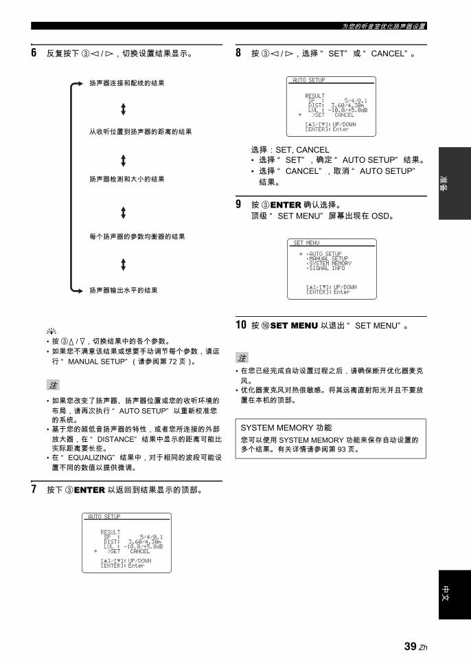
为您的听音室优化扬声器设置准
备中
文
6 反复按下 3l / h,切换设置结果显示。
y• 按 3k / n,切换结果中的各个参数。• 如果您不满意该结果或想要手动调节每个参数,请运
行 “ MANUAL SETUP” (请参阅第 72 页)。
• 如果您改变了扬声器、扬声器位置或您的收听环境的布局,请再次执行 “ AUTO SETUP” 以重新校准您的系统。
• 基于您的超低音扬声器的特性,或者您所连接的外部放大器,在 “ DISTANCE” 结果中显示的距离可能比实际距离要长些。
• 在 “ EQUALIZING” 结果中,对于相同的波段可能设置不同的数值以提供微调。
7 按下 3ENTER 以返回到结果显示的顶部。
8 按 3l / h,选择 “ SET” 或 “ CANCEL” 。
选择:SET, CANCEL• 选择 “ SET” ,确定 “ AUTO SETUP” 结果。• 选择 “ CANCEL” ,取消 “ AUTO SETUP”
结果。
9 按 3ENTER 确认选择。顶级 “ SET MENU” 屏幕出现在 OSD。
10 按 FSET MENU 以退出 “ SET MENU” 。
• 在您已经完成自动设置过程之后,请确保断开优化器麦克风。
• 优化器麦克风对热很敏感。将其远离直射阳光并且不要放置在本机的顶部。
注
扬声器连接和配线的结果
从收听位置到扬声器的距离的结果
扬声器检测和大小的结果
每个扬声器的参数均衡器的结果
扬声器输出水平的结果
[]/[]:[ENTER]:
[ p
AUTO SETUP
RESULTSP : 5/4/0.1DIST: 3.60/4.30mLVL : -10.0/+5.0dB>SET CANCEL
UP/DOWNEnter
.
注
SYSTEM MEMORY 功能您可以使用 SYSTEM MEMORY 功能来保存自动设置的多个结果。 有关详情请参阅第 93 页。
[]/[]:[ENTER]:
[ p
AUTO SETUP
RESULTSP : 5/4/0.1DIST: 3.60/4.30mLVL : -10.0/+5.0dB>SET CANCEL
UP/DOWNEnter
.
[]/[]:[ENTER]:
[ p
SET MENU
;AUTO SETUP;MANUAL SETUP;SYSTEM MEMORY;SIGNAL INFO
UP/DOWNEnter
.
39 Zh

为您的听音室优化扬声器设置
定制度量 您可以选择参数均衡器类型,开启或不开启各检查项目。
1 连接随机提供的优化器麦克风,并妥当放置它。参考第 37 页上的 “ 自动设置的基本过程” 的步骤 1-3。
2 反复按下 3k,选择 “ SETUP” 然后按下3l / h,选择期望的设置。
选择: AUTO, RELOAD• 要自动运行整个 “ AUTO SETUP” 步骤,选
择 “ AUTO” 。• 要再装入 后的 “ AUTO SETUP” 设置并且
不顾及当前设置,请选择 “ RELOAD” 。当您选择 “ RELOAD” ,OSD 上出现先前自动设置结果。参阅步骤 4 第 38 页上的进行操作。
• 只有当您先前已经运行 “ AUTO SETUP” 并且确定了其结果,“ RELOAD” 才可用。
• 如果您在步骤 2 选择 “ RELOAD” ,则无测试音调输出,且以前的自动设置结果出现在 OSD。
3 反复按下 3k / n,选择 “ WIRING” , “ DISTANCE” , “ SIZE” , “ EQ” , 或 “ LEVEL” ,然后再按下 3l / h,选择期望的设置。本机进行下列检查:
扬声器配线 WIRING
检查连接的扬声器和每个扬声器的极性。
扬声器距离 DISTANCE
检查从收听位置到每个扬声器的距离和调节每个声道的同步。
扬声器尺寸 SIZE
检查每个扬声器的频率响应以及为每个声道设置适当的低频转折。
选择:CHECK, SKIP• 要自动检查和调节该项目,选择 “ CHECK” 。• 要跳过该项目且不执行调节,选择 “ SKIP” 。
参数均衡器类型 EQ参数均衡器调节指定频带的水平。本机为听音室自动选择至关重要的频带,并调节所选择的频带,以便在听音室制造凝聚性声场。您可以在以下选项中选择参数均衡器调节的类型。选择:NATURAL, FLAT, FRONT, SKIP• 要平均输出所有较高频率被轻微加重的扬声器
的反应频率,选择 “ NATURAL” 。建议在FLAT 设置听起来有些杂乱时使用。
• 要平均化所有扬声器的频率响应,选择“ FLAT” 。如果您的所有扬声器质量类似,建议如此。
• 要根据您的前扬声器的声音调节每个扬声器的频率响应,选择 “ FRONT” 。如果您的前扬声器比您的其它扬声器质量高得多,建议如此。
• 要跳过该项目且不执行调节,选择 “ SKIP” 。
音量水平 LEVEL
检查并调节每个扬声器的音量水平。选择:CHECK, SKIP• 要自动检查和调节该项目,选择 “ CHECK” 。• 要跳过该项目且不执行调节,选择 “ SKIP” 。
4 度量设置完成后,开始自动设置过程。详情可参考 “ 自动设置的基本过程” 第 38 页上的的步骤 4-6。
注
SYSTEM MEMORY 功能您可以使用 SYSTEM MEMORY 功能来保存自动设置的多个结果。有关详情请参阅第 93 页。
40 Zh
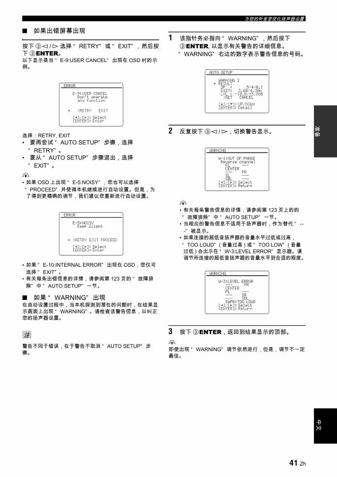
为您的听音室优化扬声器设置准
备中
文
如果出错屏幕出现
按下 3l / h 选择 “ RETRY” 或 “ EXIT” ,然后按下 3ENTER。以下显示是当 “ E-9:USER CANCEL” 出现在 OSD 时的示例。
选择: RETRY, EXIT• 要再尝试 “ AUTO SETUP” 步骤,选择
“ RETRY” 。• 要从 “ AUTO SETUP” 步骤退出,选择
“ EXIT” 。y• 如果 OSD 上出现 “ E-5:NOISY” ,您也可以选择“ PROCEED” 并使得本机继续进行自动设置。 但是,为了得到更精确的调节,我们建议您重新进行自动设置。
• 如果 “ E-10:INTERNAL ERROR” 出现在 OSD,您仅可选择 “ EXIT” 。
• 有关每条出错信息的详情,请参阅第 123 页的 “ 故障排除” 中 “ AUTO SETUP” 一节。
如果 “ WARNING” 出现在自动设置过程中,当本机探测到潜在的问题时,在结果显示画面上出现 “ WARNING” 。请检查该警告信息,以纠正您的扬声器设置。
警告不同于错误,在于警告不取消 “ AUTO SETUP” 步骤。
1 该指针务必指向 “ WARNING” ,然后按下3ENTER, 以显示有关警告的详细信息。“ WARNING” 右边的数字表示警告信息的号码。
2 反复按下 3l / h,切换警告显示。
y• 有关每条警告信息的详情,请参阅第 123 页上的的“ 故障排除” 中 “ AUTO SETUP” 一节。
• 当相应的警告信息不适用于扬声器时,作为替代 “ ---” 被显示。
• 如果连接的超低音扬声器的音量水平过低或过高,“ TOO LOUD” ( 音量过高 ) 或 “ TOO LOW” ( 音量过低 ) 会出示在 “ W-3:LEVEL ERROR” 显示器。请调节所连接的超低音扬声器的音量水平到合适的程度。
3 按下 3ENTER,返回到结果显示的顶部。y即使出现 “ WARNING” 调节依然进行,但是,调节不一定
佳。
注
[p]/[[]:[ENTER]:
ERROR
E-9:USER CANCELDon't operateany function
>RETRY EXIT
SelectEnter
.
[p]/[[]:[ENTER]:
ERROR
E-5:NOISYKeep silent
>RETRY EXIT PROCEED
SelectEnter
.
[]/[]:[ENTER]:
[ p
AUTO SETUP
WARNING 2RESULTSP : 5/4/0.1DIST: 3.60/4.30mLVL : -10.0/+5.0dB>SET CANCEL
UP/DOWNDetail
.
[p]/[[]:[ENTER]:
WARNING
W-1:OUT OF PHASEReverse channel
FL ---CENTER--- PRSL ---SBL ---
SelectReturn
[p]/[[]:[ENTER]:
WARNING
W-3:LEVEL ERROR--- FRCENTERPL ------ SR--- SBLSWFR:TOO LOUD
SelectReturn
41 Zh
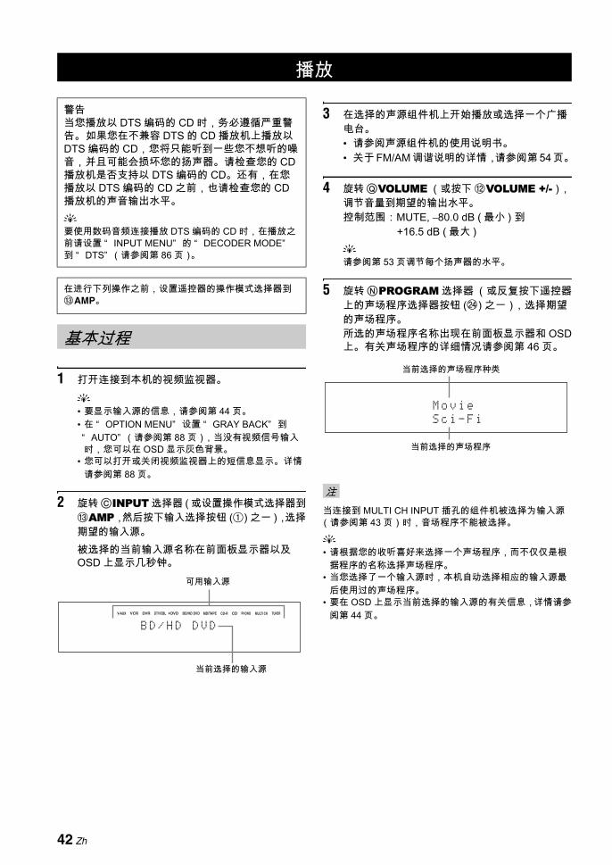
1 打开连接到本机的视频监视器。y• 要显示输入源的信息,请参阅第 44 页。• 在 “ OPTION MENU” 设置 “ GRAY BACK” 到“ AUTO” (请参阅第 88 页),当没有视频信号输入时,您可以在 OSD 显示灰色背景。
• 您可以打开或关闭视频监视器上的短信息显示。详情请参阅第 88 页。
2 旋转 CINPUT 选择器 ( 或设置操作模式选择器到CAMP,然后按下输入选择按钮 (1) 之一 ),选择期望的输入源。被选择的当前输入源名称在前面板显示器以及OSD 上显示几秒钟。
3 在选择的声源组件机上开始播放或选择一个广播电台。• 请参阅声源组件机的使用说明书。• 关于 FM/AM 调谐说明的详情,请参阅第 54 页。
4 旋转QVOLUME (或按下 BVOLUME +/-),调节音量到期望的输出水平。控制范围:MUTE, –80.0 dB ( 小 ) 到
+16.5 dB ( 大 )y请参阅第 53 页调节每个扬声器的水平。
5 旋转NPROGRAM 选择器 (或反复按下遥控器上的声场程序选择器按钮 (N) 之一),选择期望的声场程序。所选的声场程序名称出现在前面板显示器和 OSD上。有关声场程序的详细情况请参阅第 46 页。
当连接到 MULTI CH INPUT 插孔的组件机被选择为输入源(请参阅第 43 页)时,音场程序不能被选择。
y• 请根据您的收听喜好来选择一个声场程序,而不仅仅是根
据程序的名称选择声场程序。• 当您选择了一个输入源时,本机自动选择相应的输入源
后使用过的声场程序。• 要在 OSD 上显示当前选择的输入源的有关信息,详情请参
阅第 44 页。
播放
警告当您播放以 DTS 编码的 CD 时,务必遵循严重警告。 如果您在不兼容 DTS 的 CD 播放机上播放以DTS 编码的 CD,您将只能听到一些您不想听的噪音,并且可能会损坏您的扬声器。请检查您的 CD播放机是否支持以 DTS 编码的 CD。还有,在您播放以 DTS 编码的 CD 之前,也请检查您的 CD播放机的声音输出水平。y要使用数码音频连接播放 DTS 编码的 CD 时,在播放之前请设置 “ INPUT MENU” 的 “ DECODER MODE”到 “ DTS” (请参阅第 86 页)。
在进行下列操作之前,设置遥控器的操作模式选择器到CAMP。
基本过程
CD-R CD PHONO MULTI CH TUNERMD/TAPEBD/HD DVDDVDDVR DTV/CBLVCRV-AUX
B D / H D D V D
当前选择的输入源
可用输入源
注
M o v i e
S c i - F i
当前选择的声场程序
当前选择的声场程序种类
42 Zh
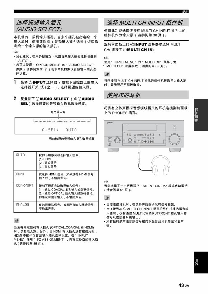
播放中
文基
本操
作
本机带有一系列输入插孔。当多个插孔被指定给一个输入源时,使用该性能 (音频输入插孔选择)切换指定给一个输入源的输入插孔。y• 我们建议,在大多数情况下设置音频输入插孔选择设置到“ AUTO” 。
• 您可以使用 “ OPTION MENU” 的 “ AUDIO SELECT”参数 (请参阅第 91 页)调节本机的默认音频输入插孔选择设置。
1 旋转CINPUT 选择器 (或按下遥控器上的输入选择器开关 (1) 之一),选择期望的输入源。
2 反复按下DAUDIO SELECT (或 9AUDIO SEL)选择想要的音频输入插孔选择设置。
当没有指定数码输入插孔 (OPTICAL,COAXIAL 和 HDMI)时,该功能无效。 另外,当 HDMI 输入插孔没有被使用时,HDMI 不能作为音频输入插孔选择设置。在 “ INPUT MENU” 使用 “ I/O ASSIGNMENT” ,再指定各自的输入插孔 ( 请参阅第 86 页 )。
使用此功能选择连接在 MULTI CH INPUT 插孔上的组件机作为输入源 (请参阅第 30 页)。
旋转前面板上的CINPUT 选择器以选择 MULTI CH( 或按下 1MULTI CH IN)。
y使用 “ INPUT MENU” 的 “ MULTI CH” 菜单,为“ MULTI CH” 设置参数 (请参阅第 85 页)。
当连接到 MULTI CH INPUT 插孔的组件机被选择为输入源时,音场程序不能被选择。
将具有立体声模拟音频缆线插头的耳机连接到前面板上的 PHONES 插孔。
y当您选择了一个声场程序,SILENT CINEMA 模式自动激活(请参阅第 51 页)。
• 当您连接耳机时,在该扬声器端子没有信号输出。• 当连接到本机 MULTI CH INPUT 插孔的组件机被选择为输
入源时,仅有通过 MULTI CH INPUTFRONT 插孔输入的信号从连接的耳机输出。
• 所有数码多声道音频信号被向下混音到耳机的左和右声道。
选择视频输入插孔 (AUDIO SELECT)
AUTO 按如下顺序自动选择输入信号:(1) HDMI(2)数码信号(3)模拟信号
HDMI 仅选择 HDMI 信号。如果没有 HDMI 信号输入时,不输出声音。
COAX/OPT 按如下顺序自动选择输入信号:(1)通过 COAXIAL 插孔输入的数码信号。(2)通过 OPTICAL 插孔输入的数码信号。如果没有信号输入,不输出声音。
ANALOG 仅选择模拟信号。如果没有输入模拟信号,不输出声音。
注
CD-R CD PHONO MULTI CH TUNERMD/TAPEBD/HD DVDDVDDVR DTV/CBLVCRV-AUX
A . S E L : A U T O
当前选择的音频输入插孔选择设置
可用输入源
选择 MULTI CH INPUT 组件机
注
使用您的耳机
注
MASTER
PURE DIRECT
VOLUME
MAIN ZONE
INPUT
OFFON
SLEEP
ZONE ON/OFF ZONE CONTROLS
MULTI ZONE
MICOPTIMIZER
EFFECT
PROGRAM
YPAO
ZONE 3
RL OPTICAL
ZONE 2
AUDIO
VIDEO AUX
SILENT CINEMA S VIDEO VIDEO
PHONES
MODETUNING
PRESET/TUNING
EDIT
FM/AMTUNINGPRESET/
MAN'L/AUTO FMMEMORY
STRAIGHT
CONTROLSELECTAUDIO TONE
A/B/C/D/E
ON/OFF
43 Zh
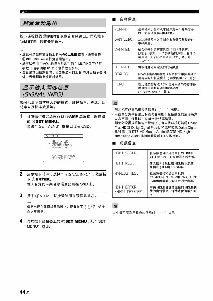
播放
按下遥控器的 DMUTE 以默音音频输出。 再次按下DMUTE,恢复音频输出。
y• 您也可以旋转前面板上的QVOLUME 或按下遥控器的BVOLUME +/- 以恢复音频输出。
• 您可以使用 “ VOLUME MENU” 的 “ MUTING TYPE”参数 (请参阅第 81 页)调节默音水平。
• 当音频输出被默音时,前面板显示器上的 MUTE 指示器闪烁,当音频输出恢复时熄灭。
您可以显示当前输入源的格式、取样频率、声道、比特率以及标志数据等。
1 设置操作模式选择器到 CAMP 然后按下遥控器的 FSET MENU。顶级 “ SET MENU” 屏幕出现在 OSD。
2 反复按下 3n,选择 “ SIGNAL INFO” ,然后按下 3ENTER。输入音源的有关音频信息出现在 OSD 上。
3 按下 3l / h,切换音频和视频信息显示。y信息出现在前面板显示器上。 反复按下 3k / n,切换显示的信息。
4 再次按下遥控器上的 FSET MENU,从“ SET MENU” 退出。
音频信息
• 当本机不能显示相应的信息时,“ ---” 出现。• 有些高分辨率音频比特流内容可能不包括独立的后环绕声
左右声道,但是以 192 kHz 比特率编码。• 即使您设置成直接输出比特流,有些播放机可能将 Dolby
TrueHD 或 Dolby Digital Plus 比特流转换成 Dolby Digital比特流;将 DTS-HD Master Audio 或 DTS-HD High Resolution Audio 比特流转换成 DTS 比特流。
视频信息
当本机不能显示相应的信息时,“ ---” 出现。
默音音频输出
显示输入源的信息 (SIGNAL INFO)
[]/[]:[ENTER]:
[ p
SET MENU
;AUTO SETUP;MANUAL SETUP;SYSTEM MEMORY;SIGNAL INFO
UP/DOWNEnter
.
FORMAT 信号格式。当本机不能探测一个数码信号时,它自动切换到模拟输入。
SAMPLING 从连续信号中为了制作离散信号每秒钟的取样数量。
CHANNEL 输入信号的源声道数目 (前 / 环绕声 /LFE)。例如,一个多声道的声轨,有 3 个前声道,2 个环绕声道和 LFE,显示为“ 3/2/0.1” 。
BITRATE 每秒钟通过给定点的比特数量。
DIALOG HDMI 视频监视器对话标准化水平预设到当前输入的比特流信号 (请参阅第 125 页)。
FLAG 在比特流信号或 PCM 信号中编码的标志数据可提示本机自动切换解码器(“ Surround EX” 等)。
注
HDMI SIGNAL 视频源信号和通过本机的 HDMI OUT 插孔输出的视频信号的类型。
HDMI RES. 输入信号 ( 模拟或 HDMI) 以及输出信号 (HDMI) 的分辨率。
ANALOG RES. 视频源信号和通过本机的COMPONENT MONITOR OUT 插孔输出的模拟视频信号的分辨率。
HDMI ERROR(HDMI MESSAGE)
有关 HDMI 音源或连接的 HDMI 装置的出错信息。详情请参阅第 120页。
注
44 Zh
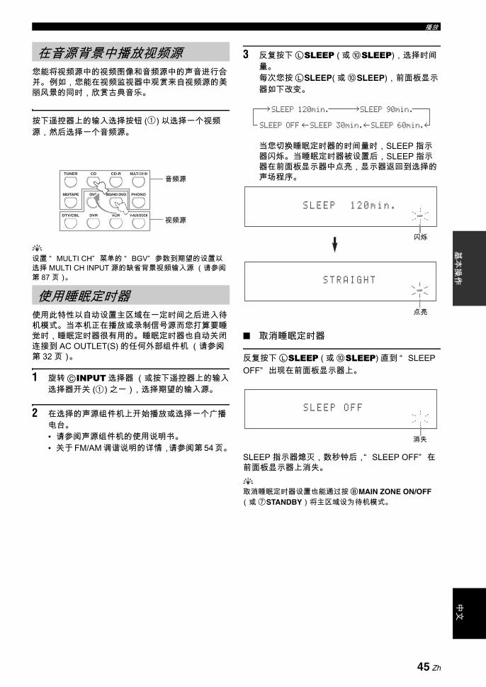
播放中
文基
本操
作
您能将视频源中的视频图像和音频源中的声音进行合并。 例如,您能在视频监视器中观赏来自视频源的美丽风景的同时,欣赏古典音乐。
按下遥控器上的输入选择按钮 (1) 以选择一个视频源,然后选择一个音频源。
y设置 “ MULTI CH” 菜单的 “ BGV” 参数到期望的设置以选择 MULTI CH INPUT 源的缺省背景视频输入源 (请参阅第 87 页)。
使用此特性以自动设置主区域在一定时间之后进入待机模式。当本机正在播放或录制信号源而您打算要睡觉时,睡眠定时器很有用的。睡眠定时器也自动关闭连接到 AC OUTLET(S) 的任何外部组件机 (请参阅第 32 页)。
1 旋转CINPUT 选择器 (或按下遥控器上的输入选择器开关 (1) 之一),选择期望的输入源。
2 在选择的声源组件机上开始播放或选择一个广播电台。• 请参阅声源组件机的使用说明书。• 关于 FM/AM 调谐说明的详情,请参阅第 54 页。
3 反复按下LSLEEP ( 或 0SLEEP),选择时间量。每次您按LSLEEP( 或 0SLEEP),前面板显示器如下改变。
当您切换睡眠定时器的时间量时,SLEEP 指示器闪烁。 当睡眠定时器被设置后,SLEEP 指示器在前面板显示器中点亮,显示器返回到选择的声场程序。
取消睡眠定时器
反复按下LSLEEP ( 或 0SLEEP) 直到 “ SLEEP OFF” 出现在前面板显示器上。
SLEEP 指示器熄灭,数秒钟后,“ SLEEP OFF” 在前面板显示器上消失。y取消睡眠定时器设置也能通过按BMAIN ZONE ON/OFF(或 7STANDBY)将主区域设为待机模式。
在音源背景中播放视频源
使用睡眠定时器
DTV/CBL VCRDVR V-AUX/DOCK
TUNER CD CD-R MULTI CH IN
DVD BD/HD DVD PHONOMD/TAPE
音频源
视频源
SLEEP 120min. SLEEP 90min.
SLEEP 60min.SLEEP 30min.SLEEP OFF
SLEEP
S L E E P 1 2 0 m i n .
闪烁
SLEEP
S T R A I G H T
点亮
S L E E P O F F
消失
45 Zh
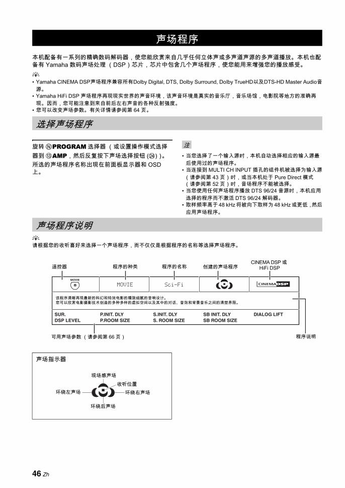
本机配备有一系列的精确数码解码器,使您能欣赏来自几乎任何立体声或多声道声源的多声道播放。本机也配备有 Yamaha 数码声场处理 (DSP)芯片,芯片中包含几个声场程序,使您能用来增强您的播放感受。y• Yamaha CINEMA DSP声场程序兼容所有Dolby Digital, DTS, Dolby Surround, Dolby TrueHD以及DTS-HD Master Audio音
源。• Yamaha HiFi DSP 声场程序再现现实世界的声音环境,该声音环境是真实的音乐厅,音乐场馆,电影院等地方的准确再
现。因而,您可能注意到来自前后左右声音的各种反射强度。• 您可以改变声场参数。有关详情请参阅第 64 页。
旋转NPROGRAM 选择器 (或设置操作模式选择器到 CAMP,然后反复按下声场选择按钮 (N))。所选的声场程序名称出现在前面板显示器和 OSD上。
• 当您选择了一个输入源时,本机自动选择相应的输入源后使用过的声场程序。
• 当连接到 MULTI CH INPUT 插孔的组件机被选择为输入源(请参阅第 43 页)时,或当本机处于 Pure Direct 模式(请参阅第 52 页)时,音场程序不能被选择。
• 当您使用任何声场程序播放 DTS 96/24 音源时,本机应用选择的程序而不激活 DTS 96/24 解码器。
• 取样频率高于 48 kHz 将被向下取样为 48 kHz 或更低,然后应用声场程序。
y请根据您的收听喜好来选择一个声场程序,而不仅仅是根据程序的名称等选择声场程序。
声场程序
选择声场程序
注
声场程序说明
声场指示器
DIALOG LIFTSB ROOM SIZES. ROOM SIZESB INIT. DLYS.INIT. DLY
P.ROOM SIZE
Sci-FiMOVIE
P.INIT. DLYSUR.DSP LEVEL
8
MOVIE
该程序清晰再现 新的科幻和特效电影的精致细腻的音响设计。 您可以欣赏电影摄影技术创造的多种多样的虚拟空间以及其中的对话、音效和背景音乐之间的清楚界限。
可用声场参数 (请参阅第 66 页) 程序说明
遥控器 程序的名称 创建的声场程序 CINEMA DSP 或
HiFi DSP程序的种类
现场感声场收听位置
环绕左声场 环绕右声场
环绕后声场
46 Zh

声场程序中
文基
本操
作
对于音乐音源y对于音乐音源,我们也推荐使用 Pure Direct 模式 (请参阅第 52 页),“ STRAIGHT” 模式 (请参阅第 51 页)或环绕声解码器模式 (请参阅第 69 页)。
CLASSICAL Hall in Munich
该声场程序模拟坐落在慕尼黑的大约有 2500 个座位的音乐大厅,它使用流行的木质内装,这也是欧洲音乐大厅的常规标准。精细华美的回响传播充足,构成一种祥和的气氛。收听者的虚拟座位在舞台的中部偏左。
DSP LEVELINIT. DLY
ROOM SIZELIVENESS
DIALOG LIFT
CLASSICAL Hall in Vienna
这是一个 1700 座的中等大小的音乐厅,具有维也纳传统的鞋盒形状。立柱和装饰雕刻图案产生极为复合的反射,在听众的四周能产生非常完整、饱满的声音。
DSP LEVELINIT. DLY
ROOM SIZELIVENESS
DIALOG LIFT
7
ENTERTAIN
5
CLASSICAL
HiFi DSP
7
ENTERTAIN
5
CLASSICAL
HiFi DSP
CLASSICAL Hall in Amsterdam
该程序再现一个巨大的可容纳大约 2200 个座位的鞋盒型的音乐厅。声音传播自由,反射丰富且愉悦。
DSP LEVELINIT. DLY
ROOM SIZELIVENESS
DIALOG LIFT
CLASSICAL Church in Freiburg
位于南德国,巨大的石材建筑的教堂,尖顶塔有 120 m 高。其长而窄的形状以及高的天花板使得回响时间延长,而初始反射时间有限。所以,丰富的回响而不是声音自身再现了教堂的氛围。
DSP LEVELINIT. DLY
LIVENESSREV.TIME
REV.DELAYREV. LEVEL
DIALOG LIFT
CLASSICAL Chamber
该程序再现像大礼堂那样的具有高天花板的相对宽广的空间。它提供适合于宫廷音乐和室内音乐的悦耳的回响。
DSP LEVELINIT. DLY
LIVENESSREV.TIME
REV.DELAYREV. LEVEL
DIALOG LIFT
LIVE/CLUB Village Vanguard
位于纽约第 7 大街的爵士俱乐部。这个小俱乐部有低矮的天花板,使得强烈的反射会聚到位于屋角的舞台。
DSP LEVELINIT. DLY
ROOM SIZELIVENESS
DIALOG LIFT
LIVE/CLUB Warehouse Loft
货仓模仿位于梭霍的某个阁楼。来自水泥墙壁的声音反射清晰且有力。
DSP LEVELINIT. DLY
ROOM SIZELIVENESS
REV.TIMEREV.DELAY
REV. LEVELDIALOG LIFT
7
ENTERTAIN
5
CLASSICAL
HiFi DSP
7
ENTERTAIN
5
CLASSICAL
HiFi DSP
5
CLASSICAL
HiFi DSP
6
LIVE/CLUB
HiFi DSP
6
LIVE/CLUB
HiFi DSP
47 Zh

声场程序
对于各种声源
根据本机的输入源和设置,可用的声场参数和创建的声场不同。
LIVE/CLUB Cellar Club
该程序模拟具有低天花板和家庭氛围的生动的房间。真实的、生动的声场性能强有力的音响就像是听众处于小舞台的前排。
DSP LEVELINIT. DLY
ROOM SIZELIVENESS
DIALOG LIFT
LIVE/CLUB The Roxy Theatre
这是一个坐落在洛杉矶的摇滚音乐厅的声场,大约有 460 个座位。收听者的虚拟座位在大厅的中部偏左。
DSP LEVELINIT. DLY
ROOM SIZELIVENESS
REV.TIMEREV.DELAY
REV. LEVELDIALOG LIFT
LIVE/CLUB The Bottom Line
这是处于一家纽约著名的爵士俱乐部 The Bottom Line 的舞台前部的声场。场所能容纳 300 个人在声场的左右两边,提供真实和热情的声音。
DSP LEVELINIT. DLY
ROOM SIZELIVENESS
DIALOG LIFT
注
ENTERTAINMENT Sports
该程序可以让收听者欣赏立体声体育广播和浓缩的真实感觉的各种演播节目。在体育广播里,营造一种运动场气氛膨胀到恰如其分的程度,评论员和解说员的声音清晰地位于中央位置。给收听者提供在运动场现场的感觉。
DSP LEVELP. INIT. DLY
P. ROOM SIZES. INIT. DLY
S. ROOM SIZESB INIT. DLY
SB ROOM SIZEDIALOG LIFT
ENTERTAINMENT Action Game
该声场适合于动作片游戏例如赛车和 FPS 游戏等。它使用反射数据,限制各个声道的音效范围以提供强烈的游戏环境,通过增强各种效果音调,保持清晰的方向性,使人有身临其境之感。
DSP LEVELP. INIT. DLY
P. ROOM SIZES. INIT. DLY
S. ROOM SIZESB INIT. DLY
SB ROOM SIZEDIALOG LIFT
ENTERTAINMENT Roleplaying Game
该声场适于角色扮演和冒险游戏。它结合电影的声场效果以及为 “ 打斗游戏” 设计的声场效果,展现了游戏场景的深度和 3D 感觉,配合游戏中的电影场景,提供类似电影环绕声的音效。
DSP LEVELP. INIT. DLY
P. ROOM SIZES. INIT. DLY
S. ROOM SIZESB INIT. DLY
SB ROOM SIZEDIALOG LIFT
6
LIVE/CLUB
HiFi DSP
6
LIVE/CLUB
HiFi DSP
6
LIVE/CLUB
HiFi DSP
7
ENTERTAIN
7
ENTERTAIN
7
ENTERTAIN
48 Zh

声场程序中
文基
本操
作
对于音乐的视觉源
根据本机的输入源和设置,可用的声场参数和创建的声场不同。
对于电影音源y您可以选择期望的,伴随以下声场程序 (“ Mono Movie” 除外)的解码器 (SUR.)。有关详情请参阅第 71 页。
根据本机的输入源和设置,可用的声场参数和创建的声场不同。
注
ENTERTAINMENT Music Video
对于通俗,摇滚和爵士乐的实况表演,该声场提供音乐厅的形象。借助于着重声部、独奏以及韵律乐器的逼真的临场声场,还有产生大型的生动的礼堂空间的环绕声声场,使人宛若置身于热烈的生动空间。
DSP LEVELP. INIT. DLY
P. ROOM SIZES. INIT. DLY
S. ROOM SIZESB INIT. DLY
SB ROOM SIZEDIALOG LIFT
ENTERTAINMENT Recital/Opera
该程序在 佳水平控制反射量,强调人类声音的深度和透明度。“ Opera” 产生管弦乐队的乐池的回响,位于听众的前方,同时产生舞台的音响位置和感觉的现场感。环绕声声场相对适度,但是音乐大厅效果的数据备用来表现音乐的内在美。即使在长时间的歌剧表演中,听众也不会觉得疲倦。
DSP LEVELP. INIT. DLY
P. ROOM SIZES. INIT. DLY
S. ROOM SIZESB INIT. DLY
SB ROOM SIZEDIALOG LIFT
注
6
LIVE/CLUB
7
ENTERTAIN
HiFi DSP
7
ENTERTAIN
MOVIE Standard
该程序再现这样一个声场,该声场强调环绕声感觉而不扰乱多声道音频例如 Dolby Digital 和 DTS 的原始声音位置。设计具有“ 完美电影院” 的观念,观众被来自左,右和后的优美反射环绕其中。
SUR.DSP LEVEL
S. INIT. DLYS. ROOM SIZE
S. LIVENESSSB INIT. DLY
SB ROOM SIZESB LIVENESS
DIALOG LIFT
MOVIE Spectacle
该声场程序再现大场景电影的壮观感觉。 它产生宽广的影院声场,与宽银幕电影相结合,使得从很小到很大的音响都能具备极好的动态范围。
SUR.DSP LEVEL
P. INIT. DLYP. ROOM SIZE
S. INIT. DLYS. ROOM SIZE
SB INIT. DLYSB ROOM SIZE
DIALOG LIFT
8
MOVIE
8
MOVIE
MOVIE Sci-Fi
该程序清晰再现 新的科幻和特效电影的精致细腻的音响设计。 您可以欣赏电影摄影技术创造的多种多样的虚拟空间以及其中的对话、音效和背景音乐之间的清楚界限。
SUR.DSP LEVEL
P. INIT. DLYP. ROOM SIZE
S. INIT. DLYS. ROOM SIZE
SB INIT. DLYSB ROOM SIZE
DIALOG LIFT
8
MOVIE
49 Zh
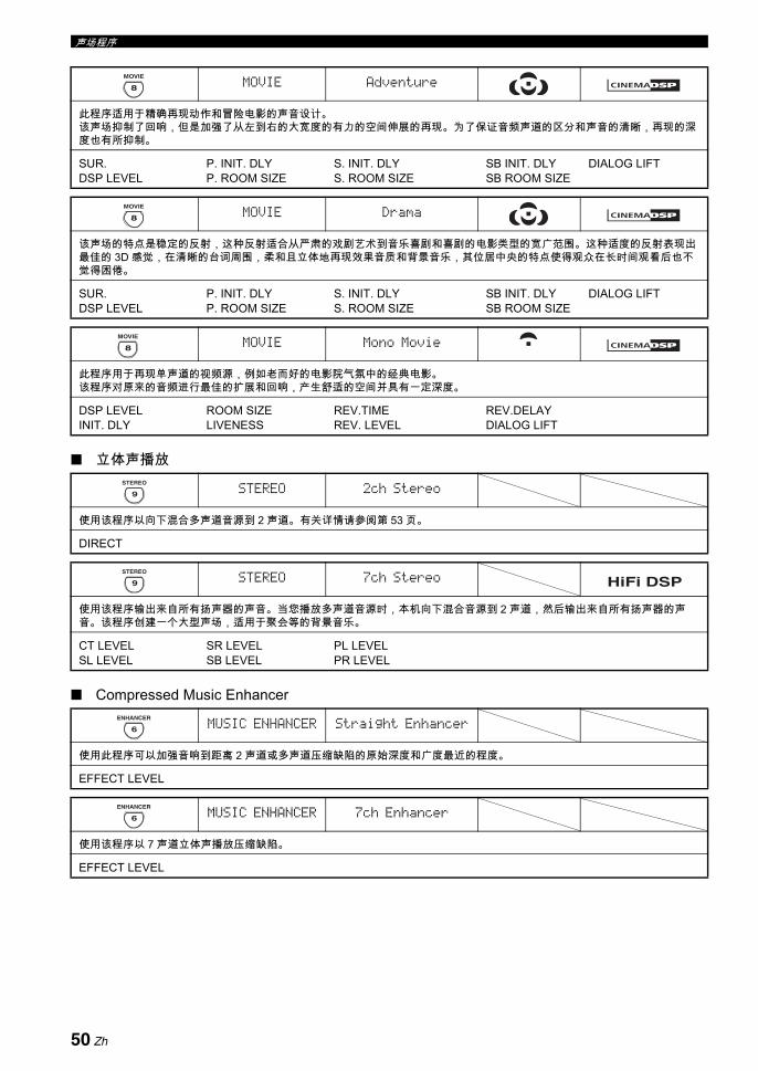
声场程序
立体声播放
Compressed Music Enhancer
MOVIE Adventure
此程序适用于精确再现动作和冒险电影的声音设计。该声场抑制了回响,但是加强了从左到右的大宽度的有力的空间伸展的再现。为了保证音频声道的区分和声音的清晰,再现的深度也有所抑制。
SUR.DSP LEVEL
P. INIT. DLYP. ROOM SIZE
S. INIT. DLYS. ROOM SIZE
SB INIT. DLYSB ROOM SIZE
DIALOG LIFT
8
MOVIE
MOVIE Drama
该声场的特点是稳定的反射,这种反射适合从严肃的戏剧艺术到音乐喜剧和喜剧的电影类型的宽广范围。这种适度的反射表现出佳的 3D 感觉,在清晰的台词周围,柔和且立体地再现效果音质和背景音乐,其位居中央的特点使得观众在长时间观看后也不
觉得困倦。
SUR.DSP LEVEL
P. INIT. DLYP. ROOM SIZE
S. INIT. DLYS. ROOM SIZE
SB INIT. DLYSB ROOM SIZE
DIALOG LIFT
8
MOVIE
MOVIE Mono Movie
此程序用于再现单声道的视频源,例如老而好的电影院气氛中的经典电影。该程序对原来的音频进行 佳的扩展和回响,产生舒适的空间并具有一定深度。
DSP LEVELINIT. DLY
ROOM SIZELIVENESS
REV.TIMEREV. LEVEL
REV.DELAYDIALOG LIFT
STEREO 2ch Stereo
使用该程序以向下混合多声道音源到 2 声道。有关详情请参阅第 53 页。
DIRECT
8
MOVIE
9
STEREO
STEREO 7ch Stereo
使用该程序输出来自所有扬声器的声音。当您播放多声道音源时,本机向下混合音源到 2 声道,然后输出来自所有扬声器的声音。该程序创建一个大型声场,适用于聚会等的背景音乐。
CT LEVELSL LEVEL
SR LEVELSB LEVEL
PL LEVELPR LEVEL
MUSIC ENHANCER Straight Enhancer
使用此程序可以加强音响到距离 2 声道或多声道压缩缺陷的原始深度和广度 近的程度。
EFFECT LEVEL
9
STEREO
HiFi DSP
6
ENHANCER
MUSIC ENHANCER 7ch Enhancer
使用该程序以 7 声道立体声播放压缩缺陷。
EFFECT LEVEL
6
ENHANCER
50 Zh

声场程序中
文基
本操
作
没有环绕声扬声器时使用声场 (Virtual CINEMA DSP)
Virtual CINEMA DSP 使得您能在没有环绕声扬声器的情况下欣赏 CINEMA DSP 或 HiFi DSP 声场程序。它创建了虚拟扬声器以再现自然的声场。当您设置 “ SUR. L/R SP” 为 “ NONE” (请参阅第78 页),当选择一个 CINEMA DSP 或 HiFi DSP 音场程序时,Virtual CINEMA DSP 会自动开启 (请参阅第 46 页)。
在以下情况中,即使 “ SUR. L/R SP” 设为 “ NONE” (请参阅第 78 页),Virtual CINEMA DSP 也不会开启:
- 当连接在 MULTI CH INPUT 插孔上的组件机作为输入源(请参阅第 43 页)时。
- 当耳机连接到 PHONES 插孔时。- 当本机处于 “ 7ch Stereo” 模式时。
用耳机欣赏多声道音源和声场程序(SILENT CINEMA)
SILENT CINEMA 使得您能使用普通耳机欣赏多声道音乐或电影音乐。如果您收听 CINEMA DSP 或 HiFi DSP 声场程序 (请参阅第 46 页),当您在PHONES 插孔上连接耳机时,SILENT CINEMA 会自动开启。被激活时,前面板显示器上的 SILENT CINEMA 指示器点亮。
• 当连接到 MULTI CH INPUT 插孔的组件机被选择为输入源(请参阅第 43 页)时,SILENT CINEMA 声场程序不能启动。
• 当选择“ Pure Direct” ( 请参阅第 52 页 ) 或“ 2ch Stereo”模式 ( 请参阅第 53 页 ),或本机处于 “ STRAIGHT” 模式时,SILENT CINEMA 不起作用。
当本机在 “ STRAIGHT” 模式时,2 声道立体声音源只从前左右扬声器输出。多声道声源被直接解码到适当的声道,而不经过额外的效果处理。
按OSTRAIGHT( 或 HSTRAIGHT),选择“ STRAIGHT” 。
y输入源的音频信号格式的名称以及现行的解码器出现在前面板显示器上。
解除 “ STRAIGHT” 模式
按下OSTRAIGHT (或 HSTRAIGHT),则“ STRAIGHT” 从前面板显示器上消失。音响效果被重新开启。y您也可以反复旋转NPROGRAM 选择器 ( 或按下期望的声场程序按钮 (N))。
注
注
在进行下列操作之前,设置遥控器的操作模式选择器到CAMP。
欣赏未处理的输入源
STRAIGHT
51 Zh

使用 Pure Direct 模式,欣赏选择音源的纯正保真度音响。当 Pure Direct 模式被激活,本机以 短线路播放选择的音源。
按下MPURE DIRECT ( 或 EPURE DIRECT) ,打开或关闭 Pure Direct 模式。前面板上的MPURE DIRECT 按钮点亮,当本机位于 Pure Direct 模式时,前面板显示器自动熄灭。
• 当本机位于 Pure Direct 模式时,本机不会通过 MONITOR OUT 插孔和 HDMI OUT 插孔输出任何视频信号。
• 当您将音频输入插孔选择设置到 “ AUTO” ,“ HDMI” 或“ COAX/OPT” (请参阅第 43 页)时以及播放比特流或多声道 PCM 音源时,本机激活相应的解码器。
• 当本机处于 Pure Direct 模式时,以下操作无法进行:- 切换声场程序- 显示 OSD- 调节 “ SET MENU” 参数 (扬声器水平设置除外)- 操作视频功能 (视频转换等)
• 只要本机关闭,Pure Direct 模式被自动取消。
y当进行操作时,前面板显示即刻点亮。
使用该性能调节前左 / 右和中央扬声器声道和超低音扬声器的低音和高音的平衡。
1 反复按下前面板上的ETONE CONTROL,选择高频响应 (TREBLE) 或低频响应 (BASS)。
2 旋转NPROGRAM 选择器,调节高频响应(TREBLE) 或低频响应 (BASS)。控制范围: -6.0 dB 到 +6.0 dB
• 如果您增加或减少高频或低频声音到一个极端的水平,环绕声扬声器的音调质量可能不匹配前左 / 右扬声器,中央扬声器和超低音扬声器的音调。
• 在以下情形 TONE CONTROL 不起作用:当 Pure Direct 模式被激活时 , 或当 MULTI CH 被选择为输入源时。
使用音频功能
在进行下列操作之前,设置遥控器的操作模式选择器到CAMP。
欣赏纯正高保真音响
注
调节音调质量
注
52 Zh
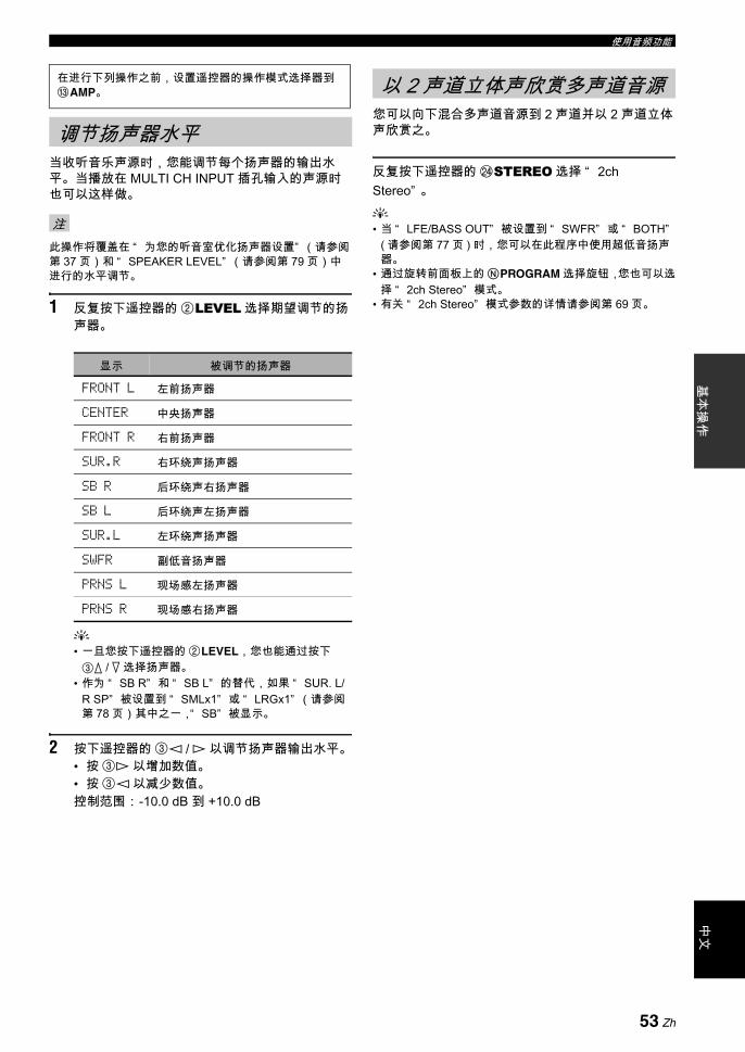
使用音频功能中
文基
本操
作
当收听音乐声源时,您能调节每个扬声器的输出水平。当播放在 MULTI CH INPUT 插孔输入的声源时也可以这样做。
此操作将覆盖在 “ 为您的听音室优化扬声器设置” (请参阅第 37 页)和 “ SPEAKER LEVEL” (请参阅第 79 页)中进行的水平调节。
1 反复按下遥控器的 2LEVEL 选择期望调节的扬声器。
y• 一旦您按下遥控器的 2LEVEL,您也能通过按下3k / n 选择扬声器。
• 作为 “ SB R” 和 “ SB L” 的替代,如果 “ SUR. L/R SP” 被设置到 “ SMLx1” 或 “ LRGx1” (请参阅第 78 页)其中之一,“ SB” 被显示。
2 按下遥控器的 3l / h 以调节扬声器输出水平。• 按 3h 以增加数值。• 按 3l 以减少数值。控制范围: -10.0 dB 到 +10.0 dB
您可以向下混合多声道音源到 2 声道并以 2 声道立体声欣赏之。
反复按下遥控器的 NSTEREO 选择 “ 2ch Stereo” 。
y• 当 “ LFE/BASS OUT” 被设置到 “ SWFR” 或 “ BOTH”
( 请参阅第 77 页 ) 时,您可以在此程序中使用超低音扬声器。
• 通过旋转前面板上的NPROGRAM 选择旋钮,您也可以选择 “ 2ch Stereo” 模式。
• 有关 “ 2ch Stereo” 模式参数的详情请参阅第 69 页。
在进行下列操作之前,设置遥控器的操作模式选择器到CAMP。
调节扬声器水平
注
显示 被调节的扬声器
FRONT L 左前扬声器
CENTER 中央扬声器
FRONT R 右前扬声器
SUR.R 右环绕声扬声器
SB R 后环绕声右扬声器
SB L 后环绕声左扬声器
SUR.L 左环绕声扬声器
SWFR 副低音扬声器
PRNS L 现场感左扬声器
PRNS R 现场感右扬声器
以 2 声道立体声欣赏多声道音源
53 Zh

有 2 种调谐方法:自动和手动。自动调谐在电台信号较强且无干扰时有效。如果您想要选择的电台信号较弱,请手动调谐该电台。您也能自动或手动储存多达 40 个电台 (A1 到 E8:5 个组各有 8 个电台)。此外,您还可以呼出任意的预设电台并且交换两个预设电台的分配。
调节所连接的 FM 和 AM 天线的方向以获得 佳的接收。
自动调谐在电台信号较强且无干扰时有效。
1 旋转前面板上的CINPUT 选择器以选择“ TUNER” 作为输入源。
2 按IFM/AM 以选择接收波段。“ FM” 或 “ AM” 出现在前面板显示器中。
3 按KTUNING MODE 使得前面板显示器上的AUTO 指示器点亮。
如果冒号 (:) 出现在前面板显示器上,无法进行调谐。 按HPRESET/TUNING 关闭冒号 (:)。
4 按GPRESET/TUNING l / h一次以开始自动调谐。当本机被调谐到一个电台时,TUNED 指示器点亮,接收到的电台的频率显示在前面板显示器中。• 按下Gh,调谐到更高频率。• 按下Gl,调谐到更低频率。
如果您想要选择的电台接收的信号较弱,请手动调谐该电台。
手动调谐到一个 FM 电台会将调谐自动切换为单声道以增强信号质量。
1 旋转前面板上的CINPUT 选择器以选择“ TUNER” 作为输入源。
2 按IFM/AM 以选择接收波段。“ FM” 或 “ AM” 出现在前面板显示器中。
3 按KTUNING MODE 使得前面板显示器上的AUTO 指示器消失。
如果冒号 (:) 出现在前面板显示器上,无法进行调谐。按HPRESET/TUNING 关闭冒号 (:)。
4 按GPRESET/TUNING l / h手动调谐到想要的电台。按住该按钮继续搜索。
FM/AM 调谐
注
自动调谐
AUTO
A F M 9 7 . 7 0 M H z
点亮无冒号 (:)
手动调谐
注
A F M 9 7 . 7 0 M H z
无冒号 (:)
54 Zh

FM/AM 调谐中
文基
本操
作
您可以使用自动预设调谐功能按次序储存 多 40 个信号较强的 FM 电台 (A1 到 E8: 5 个预设电台组,每组 8 个预设电台)。您以后只要选择预设电台的号码,就能轻易地唤出任意预设电台。
1 旋转前面板上的CINPUT 选择器以选择“ TUNER” 作为输入源。
2 按IFM/AM 以选择 “ FM” 作为接收波段。“ FM” 出现在前面板显示器中。
3 按住JMEMORY 3 秒钟以上。预设电台号码以及 AUTO 和 MEMORY 指示器闪烁。 在大约 5 秒钟之后,自动调谐预设从当前频率开始,前进到更高的频率。
当自动预设调谐完成后,前面板显示器显示 后一个预设电台的频率。
y• 您可以指定预设号码,本机将从这个号码开始储存 FM 电
台。在您进行了步骤 3 之后,按下FA/B/C/D/E,然后反复按下GPRESET/TUNING l / h,以选择即将保存第一个电台的预设电台号码。
• 您可以开始向低频率调谐以自动储存 FM 电台。按住JMEMORY超过3秒钟以后,按下HPRESET/TUNING使得冒号 (:) 从前面板显示器中消失,然后按下GPRESET/TUNING l。
• 当您在相同预设号码下储存新电台时,在该预设号码下已存在的任何储存电台数据都将被清除。
• 如果接收到的电台的数量没有达到 40(E8),自动预设调谐在搜索了所有存在的电台后自动停止。
• 自动预设调谐仅自动储存那些信号强度足够的 FM 电台。如果您想要储存的电台的信号较弱,请手动调谐它,然后遵照 “ 手动预设调谐” 的描述储存它。
• ( 仅限英国和欧洲型号 ) 自动预设调谐仅自动储存那些无线电数据系统的广播电台。
您也能手动储存多达 40 个电台 (A1 到 E8:5 个组各有 8 个电台)。
1 自动或手动调谐到一个电台。有关调谐说明请参阅第 54 页。
2 按前面板的JMEMORY。MEMORY 指示器在前面板显示器中闪烁大约 10秒钟。
3 当 MEMORY 指示器闪烁时,反复按 FA/B/C/D/E 选择一个预设电台群组 (A 到 E)。选择的预设电台组字母出现。 检查冒号 (:) 是否出现在前面板显示器上。
自动预设调谐
AUTO MEMORY
A 1 : F M 9 7 . 7 0 M H z
闪烁 闪烁
注
手动预设调谐
MEMORY
闪烁
MEMORY
A : F M 9 7 . 7 0 M H z
预设电台群组闪烁冒号 (:)
55 Zh

FM/AM 调谐
4 当 MEMORY 指示器闪烁时,按GPRESET/TUNING l / h 以选择一个预设电台号码(1 到 8)。• 按Gh 以选择一个更高的预设电台号码。• 按Gl 以选择一个更低的预设电台号码。
5 当JMEMORY指示器闪烁时,按下MEMORY。电台波段和频率以及您所选择的预设电台组和号码出现在前面板显示器中。MEMORY 指示器从前面板显示器中消失。
• 当您在相同预设号码下储存新电台时,在该预设号码下已存在的任何储存电台数据都将被清除。
• 接收模式 (立体声或单声道)与电台频率一起储存。
您只需选择储存的预设电台组和号码,就能调谐到任何一个想要的电台。
1 反复按下FA/B/C/D/E (或3A/B/C/D/E l / h),选择期望的预设电台组(A 到 E)。预设电台组字母出现在前面板显示器中,并在每次您按此按钮时发生改变。
2 反复按下GPRESET/TUNING l / h (或3PRESET/CH k / n),选择期望的预设电台号码 (1 到 8)。预设电台组和号码以及电台波段,频率出现在前面板显示器中。
注
MEMORY
A 1 : F M 9 7 . 7 0 M H z
预设电台号码 闪烁
A 1 : F M 9 7 . 7 0 M H z
显示的电台已被储存为 A1。
选择预设电台
当使用遥控器进行此操作时,设置操作模式选择开关到CSOURCE,然后按下 1TUNER 以选择“ TUNER” 作为输入源。
A 1 : F M 9 7 . 7 0 M H z
56 Zh

FM/AM 调谐中
文基
本操
作
您能将两个预设电台的分配位置互相交换。 下面的例子说明了预设电台 “ E1” 和 “ A5” 互相交换的步骤。
1 通过使用前面板的FA/B/C/D/E 和GPRESET/TUNING l / h 选择预设电台 “ E1” 。请参阅第 56 页上的 “ 选择预设电台” 。
2 按住HEDIT 大约 3 秒钟以上。“ E1” 和 MEMORY 在前面板显示器中闪烁。
3 通过使用FA/B/C/D/E 和 GPRESET/TUNING l / h 选择预设电台 “ A5” 。“ A5” 和 MEMORY 在前面板显示器中闪烁。
4 再次按HEDIT。“ EDIT E1-A5” 出现在前面板显示器上,两个预设电台的分配位置被交换。
交换预设电台
MEMORY
E 1 : F M 9 7 . 7 0 M H z
闪烁闪烁
MEMORY
A 5 : F M 9 7 . 7 0 M H z
闪烁闪烁
E D I T E 1 - A 5
57 Zh

无线电数据系统是一种在许多国家使用的 FM 电台的数据传送系统。本机可以在接收无线电数据系统电台广播的同时,接收各种无线电数据系统数据,比如 PS (节目服务),PTY (节目类型),RT (无线文字),CT (时钟时间)以及 EON (加强其他网络)等。
使用此功能显示 4 种类型的无线电数据系统信息: PS ( 节目服务 ), PTY ( 节目类型 ), RT ( 无线文字 ) 和CT ( 时钟时间 )。 前面板显示器上相应的指示器点亮。
• 仅当相应的无线电数据系统指示器在前面板显示器点亮时,您可以选择无线电数据系统显示模式之一。本机从电台接受到无线电数据系统数据需要一些时间。
• 您仅可以选择该电台提供的无线电数据系统显示模式。• 如果接收到的信号不够强,本机也许不能使用无线电数据
系统数据。特别地,即使在别的无线电数据系统显示模式可用的情况下,因为 “ RT” 模式需要大量数据,该模式也许不能使用。
• 在接收不佳的情形下,按下前面板上的KTUNING MODE,使得 AUTO 指示器从前面板显示器消失。
• 当本机接收无线电数据系统数据时,如果信号强度因为外界干扰而减弱,接收会被意外中断,前面板显示器上出现“ ...WAIT” 。
• 当 “ RT” 模式被选择时,本机可以 多显示 64 个字符的节目信息,包括变音符号。不存在的字符以 “ _” ( 下划线) 显示。
• 如果在 “ CT” 模式下接收中断,“ CT WAIT” 出现在前面板显示器上。
1 调谐到期望的无线电数据系统广播电台。• 我们推荐使用自动预设调谐来调谐到无线电数
据系统广播电台 (请参阅第 55 页)。• 您也可以使用 PTY SEEK 模式从预设的电台来
调谐到期望的无线电数据系统广播电台。
2 反复按下遥控器的 6FREQ/TEXT 选择期望的无线电数据系统模式。
• 选择 “ PS” 以显示当前接收到的无线电数据系统节目的名称。
• 选择 “ PTY” 以显示当前接收到的无线电数据系统节目的类型。
• 选择 “ RT” 以显示当前接收到的无线电数据系统节目的有关信息。
• 选择 “ CT” 以显示当前时间。
无线电数据系统调谐 ( 仅限英国和欧洲型号 )
显示无线电数据系统信息
注
CTRTPTYPS
频率显示
58 Zh
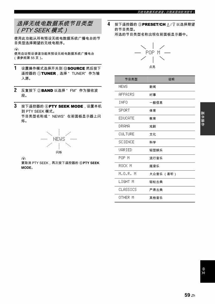
无线电数据系统调谐 ( 仅限英国和欧洲型号 )中
文基
本操
作
使用此功能从所有预设无线电数据系统广播电台的节目类型选择期望的无线电程序。y使用自动预设调谐功能来预设无线电数据系统广播电台(请参阅第 55 页)。
1 设置操作模式选择开关到 CSOURCE 然后按下遥控器的 1TUNER,选择 “ TUNER” 作为输入源。
2 反复按下 2BAND 以选择 “ FM” 作为接收波段。
3 按下遥控器的 6PTY SEEK MODE,设置本机到 PTY SEEK 模式。节目类型名称或 “ NEWS” 在前面板显示器上闪烁。
y要取消 PTY SEEK,再次按下遥控器的 6PTY SEEK MODE。
4 按下遥控器的 3PRESET/CH k / n 以选择期望的节目类型。所选的节目类型名称出现在前面板显示器中。
选择无线电数据系统节目类型(PTY SEEK 模式)
闪烁
NEWS
节目类型 说明
NEWS 新闻
AFFAIRS 时事
INFO 一般信息
SPORT 体育
EDUCATE 教育
DRAMA 戏剧
CULTURE 文化
SCIENCE 科学
VARIED 轻型娱乐
POP M 流行音乐
ROCK M 摇滚乐
M.O.R. M 大众音乐 (易听)
LIGHT M 轻松古典
CLASSICS 严肃古典
OTHER M 其他音乐
点亮
POP M
59 Zh
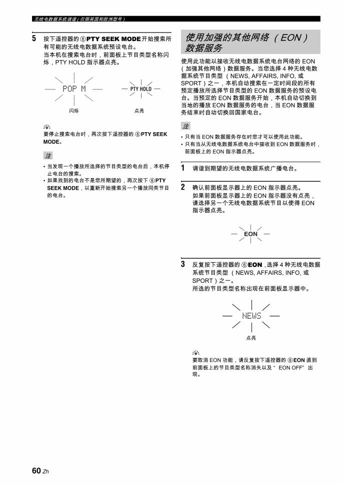
无线电数据系统调谐 ( 仅限英国和欧洲型号 )
5 按下遥控器的6PTY SEEK MODE开始搜索所有可能的无线电数据系统预设电台。当本机在搜索电台时,前面板上节目类型名称闪烁,PTY HOLD 指示器点亮。
y要停止搜索电台时,再次按下遥控器的 6PTY SEEK MODE。
• 当发现一个播放所选择的节目类型的电台后,本机停止电台的搜索。
• 如果找到的电台不是您所期望的,再次按下 6PTY SEEK MODE,以重新开始搜索另一个播放同类节目的电台。
使用此功能以接收无线电数据系统电台网络的 EON(加强其他网络)数据服务。当您选择 4 种无线电数据系统节目类型 (NEWS, AFFAIRS, INFO, 或SPORT)之一,本机自动搜索在一定时间段的所有预定播放所选择节目类型的 EON 数据服务的预设电台。当预定的 EON 数据服务开始,本机自动切换到当地的播放 EON 数据服务的电台,当 EON 数据服务结束时自动切换回国家电台。
• 只有当 EON 数据服务存在时您才可以使用此功能。• 只有当从无线电数据系统电台中接收到 EON 数据服务时,
前面板上的 EON 指示器点亮。
1 调谐到期望的无线电数据系统广播电台。
2 确认前面板显示器上的 EON 指示器点亮。如果前面板显示器上的 EON 指示器没有点亮,请选择另一个无线电数据系统节目以使得 EON指示器点亮。
3 反复按下遥控器的 6EON,选择 4 种无线电数据系统节目类型 (NEWS, AFFAIRS, INFO, 或SPORT)之一。所选的节目类型名称出现在前面板显示器中。
y要取消 EON 功能,请反复按下遥控器的 6EON 直到前面板上的节目类型名称消失以及 “ EON OFF” 出现。
注
POP M PTY HOLD
闪烁 点亮
使用加强的其他网络 (EON)数据服务
注
EON
NEWS
点亮
60 Zh

基本
操作
中文
当驳接您的 iPod 到连接在本机 DOCK 端子的 Yamaha iPod 多用平台 (比如 YDS-10,另售)时 (请参阅第31 页),您可以使用附带的遥控器欣赏 iPod 的播放。您还可以使用本机的 Compressed Music Enhancer 模式来减轻保存在 iPod 的音乐中的压缩缺陷 (比如 MP3 格式),改善音响质量 (请参阅第 50 页)。
• 仅支持具有 iPod (Click and Wheel),iPod nano,iPod mini 的 iPod。• 根据您的 iPod 的型号和软件版本的不同,有些功能也许不兼容。
y• 关于前面板显示器和 OSD 的状态讯息的完整列表,请参阅 “ 故障排除” 第 122 页上的中的 “ iPod” 一节。• 一旦您的iPod驳接到连接在本机的iPod端子的Yamaha iPod多用平台(比如YDS-10,另售),本机就开始与iPod进行信号
传送。• 当您的 iPod 与本机的连接完成后,前面板显示器上出现 “ iPod connected” 且 DOCK 指示器点亮。• 当您的 iPod 驳接到连接在本机的 DOCK 端子的 Yamaha iPod 多用平台(比如 YDS-10,另售), 只要本机电源打开,iPod 的
电池会被自动充电。您也可以选择无论本机驳接的 iPod 的电池是否充电,当本机处于待机模式时选择 “ INPUT MENU”的 “ STANDBY CHARGE” 参数 (第 87 页上的)。
• 在本机的待机模式,当驳接的 iPod 正在充电时,前面板显示器上的电池充电指示器出现(请参阅第 34 页)。一旦充电完成(或从开始充电后 4 小时),该指示器消失。
当 “ V-AUX” 被选择为输入源时,您可以控制您的iPod。iPod 的操作可以借助于本机的 OSD (菜单浏览模式),也可以不使用它 (简单遥控模式)。
遥控器操作
在简单遥控模式控制 iPod您可以使用附带的遥控器而不借助于本机的 OSD,对 iPod 进行基本操作 (播放,停止,跳越等)。y• 您可以观看保存在您的 iPod 中的照片或视频片断。• 也可以使用您的 iPod 上的控制按钮来操作。
在菜单浏览模式控制 iPod您可以使用附带的遥控器,并借助于本机的 OSD,对 iPod 进行高级操作。根据 “ OPTION MENU” 中的 “ FL SCROLL” 参数 ( 请参阅第 89 页 ),播放的歌曲的名称在前面板显示器出现。您可以在 OSD 上浏览保存在 iPod 的歌曲。此外,您还可以为 iPod 改变或调节设置,使其满足你的喜好。
• 不能使用您的 iPod 上的控制按钮来操作。• Yamaha 徽标显示在您的 iPod 的窗口上。• 有些字符也许不能在本机的前面板显示器或 OSD 上显示。
这些字符被下划线 “ _” 取代。• 在 OSD 上您不能浏览存储在 iPod 上的照片或视频文件。使
用简单遥控模式,您可以观看保存在您的 iPod 中的照片或视频片断。
使用 iPodTM 插孔
注
控制 iPodTM
在进行下列操作之前,设置遥控器的操作模式选择器到CSOURCE,然后按下 1V-AUX。
按钮 功能3 ENTER 并发菜单
k 菜单上n 菜单下l 以前菜单h 并发菜单
6 ll 向后搜索 (按住)hh 向前搜索 (按住)a 向前跳跃b 向后跳跃s 停止e 暂停 (菜单浏览模式)
播放 / 暂停 (简易遥控模式)p 播放 (菜单浏览模式)
播放 / 暂停 (简易遥控模式)F MENU 以前菜单I DISPLAY 显示
注
61 Zh
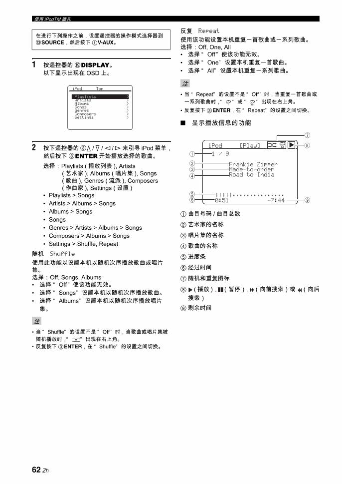
使用 iPodTM 插孔
1 按遥控器的 IDISPLAY。以下显示出现在 OSD 上。
2 按下遥控器的 3k / n / l / h 来引导 iPod 菜单,然后按下 3ENTER 开始播放选择的歌曲。选择: Playlists ( 播放列表 ), Artists
( 艺术家 ), Albums ( 唱片集 ), Songs ( 歌曲 ), Genres ( 流派 ), Composers ( 作曲家 ), Settings ( 设置 )
• Playlists > Songs• Artists > Albums > Songs• Albums > Songs• Songs• Genres > Artists > Albums > Songs• Composers > Albums > Songs• Settings > Shuffle, Repeat
随机 Shuffle
使用此功能以设置本机以随机次序播放歌曲或唱片集。选择: Off, Songs, Albums• 选择 “ Off ” 使该功能无效。• 选择 “ Songs” 设置本机以随机次序播放歌曲。• 选择 “ Albums” 设置本机以随机次序播放唱片
集。
• 当 “ Shuffle” 的设置不是 “ Off ” 时,当歌曲或唱片集被随机播放时,“ ” 出现在右上角。
• 反复按下 3ENTER,在 “ Shuffle” 的设置之间切换。
反复 Repeat
使用该功能设置本机重复一首歌曲或一系列歌曲。选择:Off, One, All• 选择 “ Off ” 使该功能无效。• 选择 “ One” 设置本机重复一首歌曲。• 选择 “ All” 设置本机重复一系列歌曲。
• 当 “ Repeat” 的设置不是 “ Off ” 时,当重复一首歌曲或一系列歌曲时,“ ” 或 “ ” 出现在右上角。
• 反复按下 3ENTER,在 “ Repeat” 的设置之间切换。
显示播放信息的功能
1 曲目号码 / 曲目总数
2 艺术家的名称
3 唱片集的名称
4 歌曲的名称
5 进度条
6 经过时间
7 随机和重复图标
8 ( 播放 ), (暂停), (向前搜索)或 (向后搜索)
9 剩余时间
在进行下列操作之前,设置遥控器的操作模式选择器到CSOURCE,然后按下 1V-AUX。
注
iPod Top
Playlists >Artists >Albums >Songs >Genres >Composers >Settings >
注
1 All
iPod[Play]
1/9FrankieZipperMade-to-orderRoadtoIndia|||||;;;;;;;;;;;;;;;0:51-7:44
All
1
234
56 9
8
7
62 Zh

基本
操作
中文
录制调节和其它操作是由录制组件机进行的。请参阅那些组件机的使用说明书。
• 当本机设为待机模式时,您不能在连接到本机的其它组件机之间进行录制。• TONE CONTROL(请参阅第 52 页)和音量设置,扬声器水平(请参阅第 79 页)和声场程序(请参阅第 46 页)的设置不
影响录制的材料。• 连接到本机的 MULTI CH INPUT 插孔的信号源不能被录制。• 在 DIGITAL INPUT 插孔输入的数码信号不会输出到模拟音频 OUT (REC) 插孔去用于录制。类似地,AUDIO IN 插孔的模拟
信号输入也不会输出到 DIGITAL OUTPUT 插孔。因此,如果您连接的信号源组件机仅提供数码或模拟信号,您仅能录制数码或模拟信号。
• 给出的输入源不是相同的 OUT (REC) 声道上的输出。• S 视频和组合视频信号独立地通过本机的视频电路。因此,当录制或复制来自仅提供 S 视频或复合视频信号的视频源组件机
的视频信号时,您仅能录制 S 视频或复合视频信号到您的 VCR。• 在 DOCK 端子输入的模拟音频和视频信号可以在模拟音频 OUT (REC) 插孔以及 DVR 或 VCR OUT 插孔输出以供录制。• 要从 CD,广播等进行录制时,请查阅您的国家的版权法。录制有版权的材料可能违反版权法。
y在您实际开始录制之前,请进行一次测试录制。
1 打开所有连接的组件机。
2 旋转CINPUT 选择器 (或按下输入选择按钮(1) 之一),选择期望的用于录制的输入源。
3 在选择的声源组件机上开始播放或选择一个广播电台。
4 开始在录制组件机上的录制。
录制
警告DTS 信号是数码比特流。 尝试数码录制 DTS 比特流将导致噪音也被录制。因此,如果您想要使用本机录制以 DTS 编码的信号源,需要进行以下考虑和调节。要在您的 DTS 兼容播放机上播放 DTS 编码的 DVD 和 CD (当使用数码音频连接时)时,请参考其操作手册进行设置已使得播放机可以输出模拟信号。
注
如果您播放一个使用混杂信号或编码信号来防止复制的视频源,图像本身可能由于那些信号而受干扰。
63 Zh
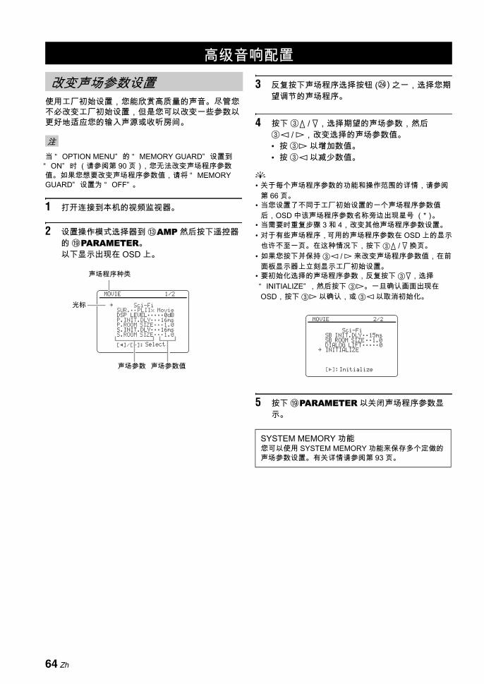
使用工厂初始设置,您能欣赏高质量的声音。尽管您不必改变工厂初始设置,但是您可以改变一些参数以更好地适应您的输入声源或收听房间。
当 “ OPTION MENU” 的 “ MEMORY GUARD” 设置到“ ON” 时 (请参阅第 90 页),您无法改变声场程序参数值。如果您想要改变声场程序参数值,请将 “ MEMORY GUARD” 设置为 “ OFF” 。
1 打开连接到本机的视频监视器。
2 设置操作模式选择器到 CAMP 然后按下遥控器的 IPARAMETER。以下显示出现在 OSD 上。
3 反复按下声场程序选择按钮 (N) 之一,选择您期望调节的声场程序。
4 按下 3k / n,选择期望的声场参数,然后3l / h,改变选择的声场参数值。• 按 3h 以增加数值。• 按 3l 以减少数值。
y• 关于每个声场程序参数的功能和操作范围的详情,请参阅
第 66 页。• 当您设置了不同于工厂初始设置的一个声场程序参数值
后,OSD 中该声场程序参数名称旁边出现星号 (*)。• 当需要时重复步骤 3 和 4,改变其他声场程序参数设置。• 对于有些声场程序,可用的声场程序参数在 OSD 上的显示
也许不至一页。在这种情况下,按下 3k / n 换页。• 如果您按下并保持 3l / h 来改变声场程序参数值,在前
面板显示器上立刻显示工厂初始设置。• 要初始化选择的声场程序参数,反复按下 3n,选择“ INITIALIZE” ,然后按下 3h。一旦确认画面出现在OSD,按下 3h 以确认,或 3l 以取消初始化。
5 按下 IPARAMETER 以关闭声场程序参数显示。
高级音响配置
改变声场参数设置
注
声场程序种类
声场参数 声场参数值
[p]/[[]:
MOVIE 1/2
Sci-FiSUR.;;PLIIx MovieDSP LEVEL;;;;;0dBP.INIT.DLY;;;16msP.ROOM SIZE;;;1.0S.INIT.DLY;;;16msS.ROOM SIZE;;;1.0
Select
.光标
SYSTEM MEMORY 功能您可以使用 SYSTEM MEMORY 功能来保存多个定做的声场参数设置。有关详情请参阅第 93 页。
[[]:
MOVIE 2/2
Sci-FiSB INIT.DLY;;15msSB ROOM SIZE;;1.0DIALOG LIFT;;;;;0INITIALIZE
Initialize
.
64 Zh
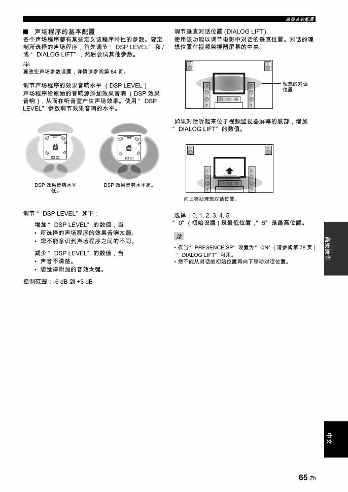
高级音响配置高
级操
作中
文
声场程序的基本配置各个声场程序都有某些定义该程序特性的参数。要定制所选择的声场程序,首先调节 “ DSP LEVEL” 和 /或 “ DIALOG LIFT” ,然后尝试其他参数。y要改变声场参数设置,详情请参阅第 64 页。
调节声场程序的效果音响水平 (DSP LEVEL)声场程序给原始的音响源添加效果音响 (DSP 效果音响),从而在听音室产生声场效果。使用 “ DSP LEVEL” 参数调节效果音响的水平。
调节 “ DSP LEVEL” 如下:
增加 “ DSP LEVEL” 的数值,当• 所选择的声场程序的效果音响太弱。• 您不能意识到声场程序之间的不同。
减少 “ DSP LEVEL” 的数值,当• 声音不清楚。• 您觉得附加的音效太强。
控制范围:-6 dB 到 +3 dB
调节垂直对话位置 (DIALOG LIFT)使用该功能以调节电影中对话的垂直位置。对话的理想位置在视频监视器屏幕的中央。
如果对话听起来位于视频监视器屏幕的底部,增加“ DIALOG LIFT” 的数值。
选择: 0, 1, 2, 3, 4, 5“ 0” ( 初始设置 ) 是 低位置,“ 5” 是 高位置。
• 仅当“ PRESENCE SP” 设置为“ ON” ( 请参阅第 78 页 )“ DIALOG LIFT” 可用。
• 您不能从对话的初始位置再向下移动对话位置。
DSP 效果音响水平低。
DSP 效果音响水平高。
注
理想的对话位置
向上移动理想对话位置。
65 Zh
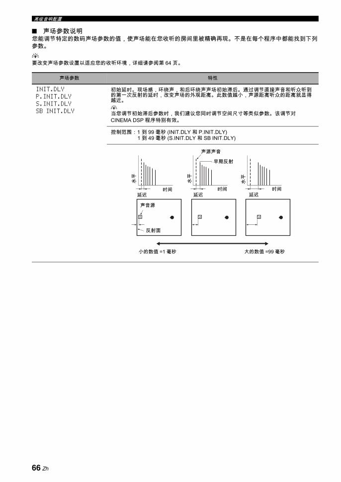
高级音响配置
声场参数说明您能调节特定的数码声场参数的值,使声场能在您收听的房间里被精确再现。不是在每个程序中都能找到下列参数。y要改变声场参数设置以适应您的收听环境,详细请参阅第 64 页。
声场参数 特性
INIT.DLYP.INIT.DLYS.INIT.DLYSB INIT.DLY
初始延时。现场感,环绕声,和后环绕声声场初始滞后。通过调节直接声音和听众听到的第一次反射的延时,改变声场的外观距离。此数值越小,声源距离听众的距离就显得越近。y当您调节初始滞后参数时,我们建议您同时调节空间尺寸等类似参数。该调节对CINEMA DSP 程序特别有效。
控制范围:1 到 99 毫秒 (INIT.DLY 和 P.INIT.DLY)1 到 49 毫秒 (S.INIT.DLY 和 SB INIT.DLY)
声源声音
早期反射
时间 时间 时间延迟 延迟 延迟
声音源
反射面
水平
小的数值 =1 毫秒 大的数值 =99 毫秒
水平
水平
66 Zh
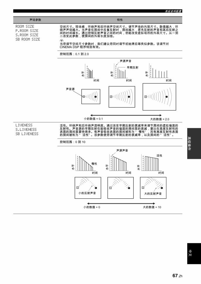
高级音响配置高
级操
作中
文
ROOM SIZEP.ROOM SIZES.ROOM SIZESB ROOM SIZE
空间尺寸。现场感,环绕声和后环绕声空间尺寸。调节声场的外观尺寸。数值越大,环绕声声场越大。当声音在房间中反复反射时,房间越大,原先反射的声音和其后反射之间的时间越长。通过控制反射声音之间的时间,您能改变虚拟场所的外观尺寸。从一到二改变此参数,使房间的外观长度加倍。y当您调节空间尺寸参数时,我们建议您同时调节初始滞后等类似参数。该调节对CINEMA DSP 程序特别有效。
控制范围:0.1 到 2.0
LIVENESSS.LIVENESSSB LIVENESS
活性。环绕声和后环绕声混响度。通过改变早期反射的衰减率来调节房间的虚拟墙面的反射性。声音源的早期反射在能吸收声音的墙面的房间里的衰减,要比在高度反射性的表面的房间里要快得多。有声音吸收表面的房间被称为 “ 惰性” ,而有高度反射性表面的房间被称为 “ 活性” 。该参数使您调节早期反射的衰减率,以及房间的 “ 活性” 。
控制范围:0 到 10
声场参数 特性
水平
水平
水平
时间 时间 时间
声源声音
早期反射
小的数值 = 0.1 大的数值 = 2.0
声音源
声源声音
水平
水平
水平
惰性
活性
时间 时间 时间
小的反射声音 大的反射声音
小的数值 = 0 大的数值 = 10
67 Zh
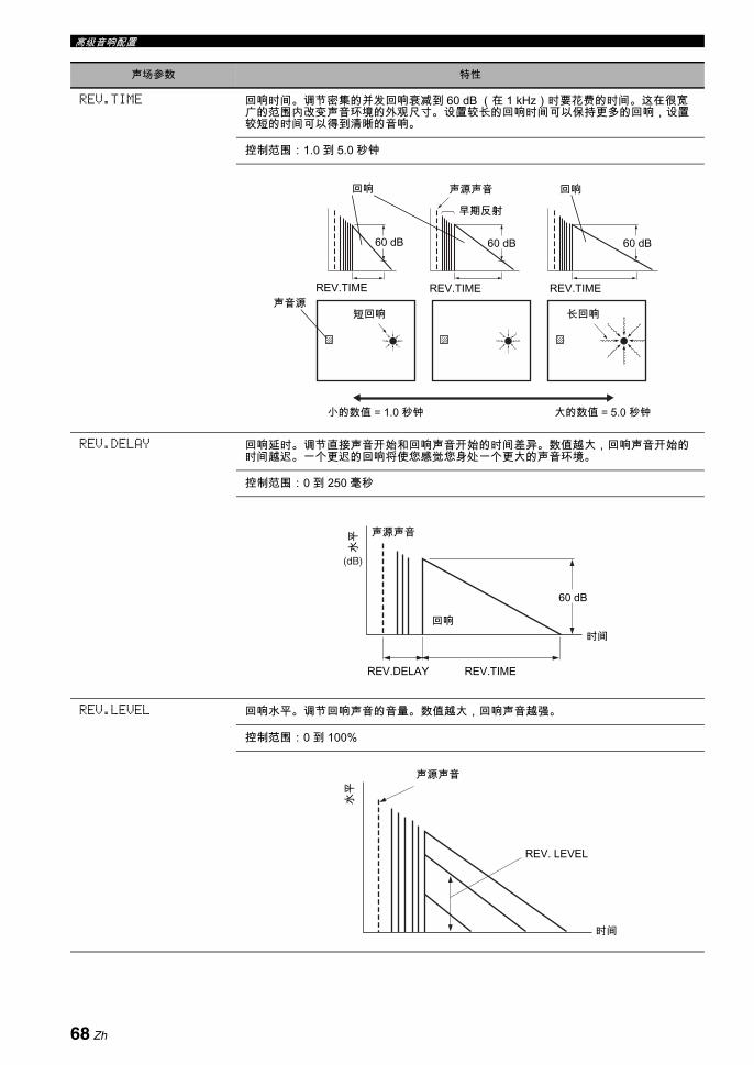
高级音响配置
REV.TIME 回响时间。调节密集的并发回响衰减到 60 dB (在 1 kHz)时要花费的时间。这在很宽广的范围内改变声音环境的外观尺寸。设置较长的回响时间可以保持更多的回响,设置较短的时间可以得到清晰的音响。
控制范围:1.0 到 5.0 秒钟
REV.DELAY 回响延时。调节直接声音开始和回响声音开始的时间差异。数值越大,回响声音开始的时间越迟。一个更迟的回响将使您感觉您身处一个更大的声音环境。
控制范围:0 到 250 毫秒
REV.LEVEL 回响水平。调节回响声音的音量。 数值越大,回响声音越强。
控制范围:0 到 100%
声场参数 特性
回响 回响声源声音
REV.TIME REV.TIME REV.TIME声音源
短回响 长回响
小的数值 = 1.0 秒钟 大的数值 = 5.0 秒钟
早期反射
60 dB 60 dB 60 dB
(dB)
水平 声源声音
回响
REV.TIMEREV.DELAY
时间
60 dB
声源声音
水平
REV. LEVEL
时间
68 Zh

高级音响配置高
级操
作中
文
为 2 声道音源选择解码器( 环绕声解码器模式 )
使用该功能通过选择的解码器播放音源。您可以在多声道播放 2 声道音源。
设置操作模式选择开关到 CAMP,然后反复按下遥控器的 KSUR. DECODE,选择环绕声解码器模式。根据您正在播放的音源的类型和您的个人喜好,您能选择期望的环绕声解码器模式。
y您可以改变解码器参数设置。按下 IPARAMETER,然后反复按下遥控器上的 3k / n 以选择期望的解码器参数。 反复按下遥控器的 3l / h,您可以改变选择的参数的值。
声场参数 特性
DIRECT( 仅限于 “ 2ch Stereo” )
2 声道直接立体声。当播放 2 声道模拟音源时,为得到纯真高保真立体声,旁路本机的解码器和 DSP 处理器。
选择:AUTO, OFF
y• 仅当“ BASS” 和“ TREBLE” 设置到 0 dB 时(请参阅第 52 页),选择“ AUTO” 以旁路解
码器,DSP 处理器和音调控制线路。• 当 “ BASS” 和 “ TREBLE” 设置到 0 dB 时,选择 “ OFF” 则不旁路解码器,DSP 处理器
和音调控制线路。• 当多声道信号被输入时,它们向下混合成 2 声道从前左右扬声器输出。• 在以下情况,前左和右声道的低频信号改向到超低音扬声器:
- “ LFE/BASS OUT” 被设置为 “ BOTH” (请参阅第 77 页)。- “ FRONT SP” 设置为 “ SMALL” (请参阅第 77 页)和 “ LFE/BASS OUT” 设置为“ SWFR” (请参阅第 77 页)。
CT LEVELSL LEVELSR LEVELSB LEVELPL LEVELPR LEVEL( 仅限于 “ 7ch Stereo” )
7 声道立体声中央,环绕声左,环绕声右和后环绕声,现场感左和现场感右水平。在 7声道立体声模式调节每个声道的音量水平。
控制范围:0 到 100%
EFFECT LEVEL( 仅限于 “ Straight Enhancer” 和 “ 7ch Enhancer” )
直接和 7- 声道 Compressed Music Enhancer 效果水平。某些音源的高频信号可能被过分加强。在此情形下,设置效果水平到 “ LOW” 。
选择:HIGH, LOW
• 选择 “ HIGH” 以得到高的效果水平。• 选择 “ LOW” 以得到低的效果水平。
选择解码器
69 Zh

高级音响配置
解码器说明
y当您为多声道数码音源选择环绕声解码器模式时 , 本机自动为各音源选择对应的解码器。
SUR. DECODESur. Decode
PRO LOGIC
任意音源 Dolby Pro Logic 处理。
SUR. DECODESur. Decode
PLIIx MoviePLII Movie
Dolby Pro Logic IIx (或 Dolby Pro Logic II)电影音源的处理。当 “ SUR.B L/R SP” 设置为 “ NONE” 时 (请参阅第78 页),Pro Logic IIx 解码器不可用。
SUR. DECODESur. Decode
PLIIx MusicPLII Music
Dolby Pro Logic IIx (或 Dolby Pro Logic II)音乐音源的处理。当 “ SUR.B L/R SP” 设置为 “ NONE” 时 (请参阅第78 页),Pro Logic IIx 解码器不可用。
PANORAMA DIMENSION CENTER WIDTH
SUR. DECODESur. Decode
PLIIx GamePLII Game
Dolby Pro Logic IIx (或 Dolby Pro Logic II)游戏音源的处理。当 “ SUR.B L/R SP” 设置为 “ NONE” 时 (请参阅第78 页),Pro Logic IIx 解码器不可用。
CENTER WIDTHDIMENSION
PLIIMusic
PLIIxMusicSUR. DECODE
Sur. Decode
PANORAMA
+10
SUR.DECODE
Dolby Pro Logic IIx (或 Dolby Pro Logic II)音乐音源的处理。当 “ SUR.B L/R SP” 设置为“ NONE” 时 (请参阅第 78 页),Pro Logic IIx 解码器不可用。
可用解码器参数 (请参阅第 71 页) 程序说明
遥控器解码器的名称
(SUR.)程序的种类和名称
+10
SUR.DECODE
+10
SUR.DECODE
+10
SUR.DECODE
+10
SUR.DECODE
SUR. DECODESur. Decode
Neo:6 Cinema
电影音源的 DTS 处理。
+10
SUR.DECODE
SUR. DECODESur. Decode
Neo:6 Music
音乐音源的 DTS 处理。
C. IMAGE
+10
SUR.DECODE
70 Zh

高级音响配置高
级操
作中
文
解码器参数说明
选择使用声场程序的解码器 (SUR.)使用此功能选择使用 MOVIE 声场程序所期望的解码器 (“ Mono Movie” 除外)。有关 MOVIE 声场程序的详细情况请参阅第 49 页。
可用解码器
解码器参数 特性
PANORAMA( 仅限于 “ PLIIx Music” 和“ PLII Music” )
Pro Logic IIx Music 和 Pro Logic II Music 全景。将立体声信号输送到环绕声扬声器以及前扬声器以得到环回效果。
选择:OFF, ON
DIMENSION( 仅限于 “ PLIIx Music” 和“ PLII Music” )
Pro Logic IIx Music 和 Pro Logic II Music 方位。调节声场向前或向后。
控制范围:-3 (向后)到 +3 (向前)
初始设置:STD ( 标准 )
CENTER WIDTH( 仅限于 “ PLIIx Music” 和“ PLII Music” )
Pro Logic IIx Music 和 Pro Logic II Music 中央宽度。朝向中央扬声器或朝向前左和右扬声器方向完全移动中央声道输出。值越大,越朝向前左和右扬声器偏移中央声道输出。
控制范围:0 (中央声道声音仅从中央扬声器输出)到7 (中央声道声音仅从前左和前右扬声器输出)
初始设置:3
C.IMAGE( 仅限于 “ Neo:6 Music” )
DTS Neo:6 Music 中央声像。相对于中央声道调节前左和右声道输出,以使得中央声道按照需要占有优势的多少。
控制范围:0.0 (中央声道声音仅从前左右扬声器输出)到1.0 (中央声道声音仅从中央扬声器输出)
初始设置:0.3
解码器 功能
PLIIx MoviePLII Movie
Dolby Pro Logic IIx (或 Dolby Pro Logic II)电影音源的处理。 当 “ SUR.B L/R SP” 设置为“ NONE” 时 (请参阅第 78页),Pro Logic IIx 解码器不可用。
Neo:6 Cinema 电影音源的 DTS 处理
71 Zh

您能使用下列 “ SET MENU” 中的参数以调节一系列系统设置并定制本机的操作方式。改变初始设置 (在每个参数下以粗体指示)以反映您的收听环境的需要。
自动设置 AUTO SETUP
使用此功能可以自动调节扬声器和系统参数 (请参阅第 37 页)。
手动设置 MANUAL SETUP
使用此功能可以手动调节扬声器和系统参数。
基本菜单 1 BASIC MENU
定制本机 (MANUAL SETUP)
菜单 参数 功能 页
A)SPEAKER SET LFE/BASS OUT 选择输出 LFE (低频效果)和低频信号的扬声器。 77
FRONT SP 选择前扬声器的尺寸。 77
CENTER SP 选择中央扬声器的尺寸。 77
SUR. L/R SP 选择环绕声扬声器的尺寸和数目。 78
SUR.B L/R SP 选择后环绕声扬声器的尺寸和数目。 78
PRESENCE SP 选择本机是否使用现场感扬声器。 78
CROSS OVER 选择在 “ SPEAKER SET” 设置为 “ SML” (或“ SMALL” )或者 “ NONE” 的所有扬声器的转折频率 ( 请参阅第 77 页 和 78)。
78
SUBWOOFER PHASE 如果低音缺少或不清晰,调节您的超低音扬声器的相位。 79
PRIORITY 当使用 CINEMA DSP 声场程序播放包含后环绕声信号的信号源时,选择是现场感扬声器优先还是后环绕声扬声器优先。
79
B)SPEAKER LEVEL FR.L/FR.R/CENT./SUR.L/SUR.R/SB L/SB R/SWFR/PR.L/PR.R
调节前左和环绕声左扬声器以及在 “ SPEAKER SET” (请参阅第 77 页)选择的各扬声器间的音量水平平衡。
79
C)SP DISTANCE UNIT 选择调节扬声器距离的单位。 80
FRONT L/FRONT R/CENTER/SUR. L/SUR. R/SB L/SB R/SWFR/PRNS L/PRNS R
调节每个扬声器的距离,以及施加到相应声道的延时。 80
D)TEST TONE 对于 “ SPEAKER SET” ,“ SPEAKER LEVEL” 和 “ SP DISTANCE” 设置,打开或关闭测试音调输出。
80
72 Zh
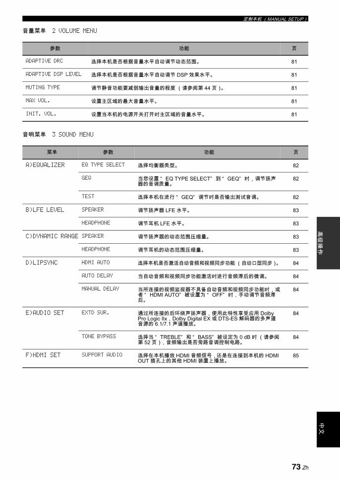
定制本机 (MANUAL SETUP)高
级操
作中
文
音量菜单 2 VOLUME MENU
音响菜单 3 SOUND MENU
参数 功能 页
ADAPTIVE DRC 选择本机是否根据音量水平自动调节动态范围。 81
ADAPTIVE DSP LEVEL 选择本机是否根据音量水平自动调节 DSP 效果水平。 81
MUTING TYPE 调节静音功能要减弱输出音量的程度 (请参阅第 44 页)。 81
MAX VOL. 设置主区域的 大音量水平。 81
INIT. VOL. 设置当本机的电源开关打开时主区域的音量水平。 81
菜单 参数 功能 页
A)EQUALIZER EQ TYPE SELECT 选择均衡器类型。 82
GEQ 当您设置 “ EQ TYPE SELECT” 到 “ GEQ” 时,调节扬声器的音调质量。
82
TEST 选择本机在进行 “ GEQ” 调节时是否输出测试音调。 82
B)LFE LEVEL SPEAKER 调节扬声器 LFE 水平。 83
HEADPHONE 调节耳机 LFE 水平。 83
C)DYNAMIC RANGE SPEAKER 调节扬声器的动态范围压缩量。 83
HEADPHONE 调节耳机的动态范围压缩量。 83
D)LIPSYNC HDMI AUTO 选择本机是否激活自动音频和视频同步功能 (自动口型同步)。 84
AUTO DELAY 当自动音频和视频同步功能激活时进行音频滞后的微调。 84
MANUAL DELAY 当所连接的视频监视器不具备自动音频和视频同步功能时,或者 “ HDMI AUTO” 被设置为 “ OFF” 时,手动调节音频滞后。
84
E)AUDIO SET EXTD SUR. 通过所连接的后环绕声扬声器,使用此特性享受应用 Dolby Pro Logic IIx,Dolby Digital EX 或 DTS-ES 解码器的多声道音源的 6.1/7.1 声道播放。
84
TONE BYPASS 选择当 “ TREBLE” 和 “ BASS” 被设定为 0 dB 时 (请参阅第 52 页),音频输出是否旁路音调控制电路。
84
F)HDMI SET SUPPORT AUDIO 选择在本机播放 HDMI 音频信号,还是在连接到本机的 HDMI OUT 插孔上的其他 HDMI 装置上播放。
85
73 Zh

定制本机 (MANUAL SETUP)
输入菜单 4 INPUT MENU
下面介绍的一些参数未必对所有输入源有用,某些参数只能用于特定的输入源。
任选菜单 5 OPTION MENU
注
参数 功能 页
I/O ASSIGNMENT 如果本机的初始设置不能适应您的需要,根据所使用的组件机分配输入 / 输出插孔。
86
INPUT RENAME 改变 OSD 和前面板显示器上的输入源名称。 86
VOL. TRIM 调节输入到各个插孔的信号的水平。 86
DECODER MODE 切换解码器活动模式。 您可以为 DTS 信号指定再分配的数码输入插孔。 86
STANDBY CHARGE 当本机处于待机模式时,选择本机上驳接的 iPod 的电池充电与否 (请参阅第 61页)。
87
BGV 选择在 MULTI CH INPUT 插孔输入的音源的背景里播放的视频源。 87
INPUT CH 选择从外部解码器输入声道数。 87
FRONT 当您设置 “ INPUT CH” 为 “ 8CH” 时,选择模拟插孔作为来自外部解码器的前方声道信号的输入插孔。
87
菜单 参数 功能 页
A)DISPLAY SET DIMMER 调节前面板显示器的亮度。 88
OSD SHIFT 调节 OSD 的垂直位置。 88
GRAY BACK 选择在没有视频信号输入时,您的视频监视器是否显示灰色背景。
88
SHORT MESSAGE 选择当您进行了某些操作之后,本机是否在视频监视器上显示短讯。
88
ON SCREEN 设置当您进行了某些操作之后 ,iPod 菜单在 OSD 上显示的时间。
88
FL SCROLL 选择在前面板显示器上显示您的 iPod 信息的模式。 89
74 Zh

定制本机 (MANUAL SETUP)高
级操
作中
文
系统记忆 SYSTEM MEMORY
使用此功能可以创建您喜欢的设置,并将各设置分配到各个 MSYSTEM MEMORY 按钮 ( 请参阅第 93 页 )。
信号信息 SIGNAL INFO
使用此功能可以检查音频信号信息 (请参阅第 44 页)。
B)VIDEO SET VIDEO CONV. 选择是否转换通过 VIDEO 和 S VIDEO 和 COMPONENT VIDEO 插孔输入的视频信号。
89
COMPONENT I/P 选择本机是否激活通过 VIDEO,S VIDEO 和 COMPONENT VIDEO 插孔输入的模拟视频信号的模拟隔行扫描 / 逐行扫描转换,这可以使得模拟视频信号从 480i (NTSC)/ 576i (PAL)非隔行化到 480p / 576p ,并通过 COMPONENT MONITOR OUT 插孔输出。
89
HDMI SCALING 选择本机是否激活 HDMI 的模拟视频信号提升转换;提升转换可以将 VIDEO, S VIDEO 和 COMPONENT VIDEO 插孔输入的模拟视频信号转换,提升后的视频信号在 HDMI OUT插孔输出。
89
HDMI ASPECT 调节 HDMI OUT 插孔上输出的模拟视频信号的宽高比。 90
C)MEMORY GUARD 防止意外地改变声场程序参数值以及其它系统设置。 90
D)INIT. CONFIG AUDIO SELECT 指定打开本机电源时,连接在 DIGITAL INPUT 插孔的输入源的缺省音频输入插孔选择的设置。
91
DECODER MODE 指定打开本机电源时,连接在 DIGITAL INPUT 插孔上的输入源的默认解码器模式。
91
EXTD SUR. 指定打开本机电源时,连接在 DIGITAL INPUT 插孔上的输入源的扩展解码器模式。
91
E)ZONE SET AMP 选择 Zone 2 或 Zone 3 扬声器如何放大。 91
VOLUME 选择本机是否控制在 ZONE OUT (ZONE 2 或 ZONE 3)插孔输出的音频信号的音量水平。
92
MAX VOL. 调节 Zone 2 或 Zone 3 的 大音量水平。 92
INIT. VOL. 设置当本机的电源开关打开时 Zone 2 或 Zone 3 的音量水平。
92
菜单 参数 功能 页
75 Zh
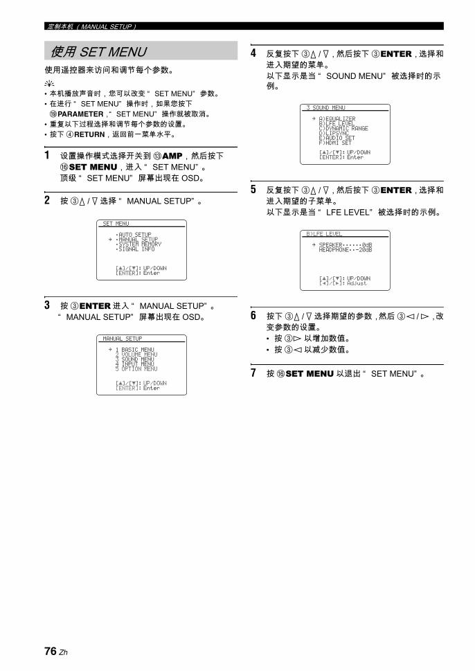
定制本机 (MANUAL SETUP)
使用遥控器来访问和调节每个参数。y• 本机播放声音时,您可以改变 “ SET MENU” 参数。• 在进行 “ SET MENU” 操作时,如果您按下IPARAMETER,“ SET MENU” 操作就被取消。
• 重复以下过程选择和调节每个参数的设置。• 按下 4RETURN,返回前一菜单水平。
1 设置操作模式选择开关到 CAMP,然后按下FSET MENU,进入 “ SET MENU” 。顶级 “ SET MENU” 屏幕出现在 OSD。
2 按 3k / n 选择 “ MANUAL SETUP” 。
3 按 3ENTER 进入 “ MANUAL SETUP” 。“ MANUAL SETUP” 屏幕出现在 OSD。
4 反复按下 3k / n,然后按下 3ENTER,选择和进入期望的菜单。以下显示是当 “ SOUND MENU” 被选择时的示例。
5 反复按下 3k / n,然后按下 3ENTER,选择和进入期望的子菜单。以下显示是当 “ LFE LEVEL” 被选择时的示例。
6 按下 3k / n 选择期望的参数,然后 3l / h,改变参数的设置。• 按 3h 以增加数值。• 按 3l 以减少数值。
7 按 FSET MENU 以退出 “ SET MENU” 。
使用 SET MENU
[]/[]:[ENTER]:
[ p
SET MENU
;AUTO SETUP;MANUAL SETUP;SYSTEM MEMORY;SIGNAL INFO
UP/DOWNEnter
.
[]/[]:[ENTER]:
[ p
MANUAL SETUP
1 BASIC MENU2 VOLUME MENU3 SOUND MENU4 INPUT MENU5 OPTION MENU
UP/DOWNEnter
.
[]/[]:[ENTER]:
[ p
3 SOUND MENU
A)EQUALIZERB)LFE LEVELC)DYNAMIC RANGED)LIPSYNCE)AUDIO SETF)HDMI SET
UP/DOWNEnter
.
[]/[]:[p]/[[]:
[ p
B)LFE LEVEL
SPEAKER;;;;;;0dBHEADPHONE;;-20dB
UP/DOWNAdjust
.
76 Zh
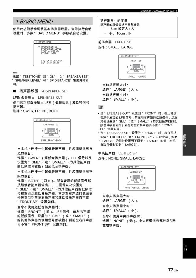
定制本机 (MANUAL SETUP)高
级操
作中
文
使用此功能手动调节基本扬声器设置。当您执行自动设置时,多数 “ BASIC MENU” 参数被自动设置。
y设置 “ TEST TONE” 到 “ ON” ,为 “ SPEAKER SET” , “ SPEAKER LEVEL” 和 “ SP DISTANCE” 输出测试音调。
扬声器设置 A)SPEAKER SET
LFE/ 低音输出 LFE/BASS OUT
使用该功能选择输出 LFE (低频效果)和低频信号扬声器。选择:SWFR, FRONT, BOTH
当本机上连接一个超低音扬声器,且您期望得到自然的低音 :选择 “ SWFR” (超低音扬声器)。LFE 信号以及设置为 “ SML” (或 “ SMALL” )的其他扬声器的低频信号被指引到超低音扬声器。当本机上连接一个超低音扬声器,且您期望得到充实的低音 :选择 “ BOTH” (双方)。所有音源的低频信号都从超低音扬声器输出。 LFE 信号以及设置为“ SML” (或 “ SMALL” )的其他扬声器的低频信号被指引到超低音扬声器。前方左右声道的低频信号被指引到前左右扬声器和超低音扬声器而不管“ FRONT SP” 设置如何。当您不使用超低音扬声器时 :选择 “ FRONT” (前)。LFE 信号,前左右声道的低频信号,设置为 “ SML” (或 “ SMALL” )的其他扬声器的低频信号都被指引到前左右扬声器而不管 “ FRONT SP” 设置如何。
前扬声器 FRONT SP
选择:SMALL, LARGE
当前扬声器大时 :选择 “ LARGE” (大)。当前扬声器小时 :选择 “ SMALL” (小)。
• 当 “ LFE/BASS OUT” 设置到 “ FRONT” 时,在比特流音源中发现的 LFE 信号,前左和右声道的低频信号,以及其他设置到 “ SML” (或 “ SMALL” )的其他扬声器的低频信号被全部指引到前方左右扬声器而不管 “ FRONT SP” 设置如何。
• 当 “ LFE/BASS OUT” 设置为 “ FRONT” 时,您仅可以选择 “ FRONT SP” 为 “ FRONT SP” 。在此之前,如果“ LARGE” 的值被设置到不同于 “ LARGE” 的值,本机自动将值改变到 “ LARGE” 。
中央扬声器 CENTER SP
选择:NONE, SMALL, LARGE
当中央扬声器大时 :选择 “ LARGE” (大)。当中央扬声器小时 :选择 “ SMALL” (小)。当您不使用中央扬声器时 :选择 “ NONE” (无)。中央声道信号都被指引到左右扬声器。
1 BASIC MENU
[]/[]:[ENTER]:
[ p
1 BASIC MENU
A)SPEAKER SETB)SPEAKER LEVELC)SP DISTANCED)TEST TONE
UP/DOWNEnter
.
A)SPEAKER SET
LFE/BASS OUT
SWFR FRONT>BOTH
扬声器尺寸的度量扬声器的超低音扬声器部分是
– 16cm 或更大 : 大– 小于 16cm : 小
注
A)SPEAKER SET
FRONT SP
SMALL >LARGE
A)SPEAKER SET
CENTER SP
NONE >SMALL LARGE
77 Zh
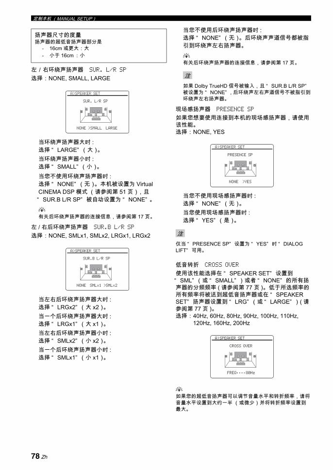
定制本机 (MANUAL SETUP)
左/右环绕声扬声器 SUR. L/R SP
选择:NONE, SMALL, LARGE
当环绕声扬声器大时 :选择 “ LARGE” (大)。当环绕声扬声器小时 :选择 “ SMALL” (小)。当您不使用环绕声扬声器时 :选择 “ NONE” (无)。本机被设置为 Virtual CINEMA DSP 模式 (请参阅第 51 页),且“ SUR.B L/R SP” 被自动设置为 “ NONE” 。y有关后环绕声扬声器的连接信息,请参阅第 17 页。
左 / 右后环绕声扬声器 SUR.B L/R SP
选择:NONE, SMLx1, SMLx2, LRGx1, LRGx2
当左右后环绕声扬声器大时 :选择 “ LRGx2” (大 x2)。当一个后环绕声扬声器大时 :选择 “ LRGx1” (大 x1)。当左右后环绕声扬声器小时 :选择 “ SMLx2” (小 x2)。当一个后环绕声扬声器小时 :选择 “ SMLx1” (小 x1)。
当您不使用后环绕声扬声器时 :选择 “ NONE” (无)。后环绕声声道信号都被指引到环绕声左右扬声器。
y有关后环绕声扬声器的连接信息,请参阅第 17 页。
如果 Dolby TrueHD 信号被输入,且 “ SUR.B L/R SP”被设置为 “ NONE” , 后环绕声左右声道信号不被指引到环绕声左右扬声器。
现场感扬声器 PRESENCE SP
如果您想要使用连接到本机的现场感扬声器,请使用该性能。选择:NONE, YES
当您不使用现场感扬声器时 :选择 “ NONE” (无)。当您使用现场感扬声器时 :选择 “ YES” (是)。
仅当 “ PRESENCE SP” 设置为 “ YES” 时 “ DIALOG LIFT” 可用。
低音转折 CROSS OVER
使用该性能选择在 “ SPEAKER SET” 设置到“ SML” (或 “ SMALL” )或者 “ NONE” 的所有扬声器的分频频率 ( 请参阅第 77 页 )。低于所选频率的所有频率将被送到超低音扬声器或在 “ SPEAKER SET” 扬声器设置到 “ LRG” (或 “ LARGE” )( 请参阅第 77 页 )。选择:40Hz, 60Hz, 80Hz, 90Hz, 100Hz, 110Hz,
120Hz, 160Hz, 200Hz
y如果您的超低音扬声器可以调节音量水平和转折频率,请将音量水平设置到大约一半 (或微少)并将转折频率设置到
大。
扬声器尺寸的度量扬声器的超低音扬声器部分是
- 16cm 或更大:大- 小于 16cm :小
A)SPEAKER SET
SUR. L/R SP
NONE >SMALL LARGE
A)SPEAKER SET
SUR.B L/R SP
NONE SMLx1 >SMLx2
注
注
A)SPEAKER SET
PRESENCE SP
NONE >YES
A)SPEAKER SET
CROSS OVER
FREQ;;;;80Hz
78 Zh

定制本机 (MANUAL SETUP)高
级操
作中
文
超低音扬声器相位 SUBWOOFER PHASE
如果低音缺少或不清晰,请使用此特性调节您的超低音扬声器相位。
现场感 / 后环绕声声道优先权 PRIORITY
当使用声场程序播放 2- 声道音源信号源时,使用该性能可以选择是现场感扬声器优先还是后环绕声扬声器优先。
y有关在声场程序来自各个扬声器的声音输出的详情,请参阅本说明书末尾的 “ 附录” 中的 “ 各声场程序的声音输出” 。
扬声器水平 B)SPEAKER LEVEL
使用该性能置以在前左扬声器或环绕声左扬声器和在“ SPEAKER SET” (请参阅第 77 页)中所选的每个扬声器之间,手动平衡扬声器的水平。控制范围:-10.0 dB 到 +10.0 dB控制步距:0.5 dB初始设置:FR.L/FR.R/SWFR/PR.L/PR.R: 0 dBCENT./SUR.L/SUR.R/SB L/SB R: -1.0 dB
y• 如果您的超低音扬声器可以调节音量水平和转折频率,请
将音量水平设置到大约一半 (或微少)并将转折频率设置到 大。
• 设置 “ TEST TONE” 到 “ ON” ,为 “ SPEAKER LEVEL” 设置 (请参阅第 80 页)输出测试音调。
• 有效的扬声器声道根据扬声器的设置有所不同。• 作为 “ SB L” 和 “ SB R” 的替代,如果 “ SUR. L/R
SP” 被设置到 “ SMLx1” 或 “ LRGx1” (请参阅第 78页)其中之一,“ SB” 被显示。
选择 功能
NORMAL ( 正常 )
不要反转超低音扬声器的相位。
REVERSE( 反转 )
设置超低音扬声器的相位到反转。
选择 功能
PRNS 使用现场感扬声器。
SUR.B 使用后环绕声扬声器。
A)SPEAKER SET
SUBWOOFER PHASE
>NORMAL REVERSE
A)SPEAKER SET
PRIORITY
PRNS >SUR.B
SPEAKER LEVEL 被调节的扬声器
FR.L 左前扬声器
FR.R 右前扬声器
CENT. 中央扬声器
SUR.L 左环绕声扬声器
SUR.R 右环绕声扬声器
SB L 后环绕声左扬声器
SB R 后环绕声右扬声器
SWFR 副低音扬声器
PR.L 现场感左扬声器
PR.R 现场感右扬声器
注
B)SPEAKER LEVEL 1/2
FR.LFR.RCENT.SUR.LSUR.R
.
B)SPEAKER LEVEL 2/2
SB LSB RSWFRPR.LPR.R
.
79 Zh

定制本机 (MANUAL SETUP)
扬声器距离 C)SP DISTANCE
使用此特性以手动调节每个扬声器的距离,以及施加到相应声道的延时。理想的情况是,每个扬声器应该和主要收听位置的距离是相同的。但是,这在大多数的家庭情况下是不可能的。因此,必须给每个扬声器施加一定数量的延时,使得所有声音到达收听位置时的时间相同。
扬声器距离调节的单位 UNIT
初始设置:[ 美国和加拿大型号 ]:feet (ft) [ 其它型号 ]:meters (m)
扬声器距离控制范围:0.30 到 24.00 m (1.0 到 80.0 ft)控制步距:0.10 m (0.5 ft)初始设置:FRONT L/FRONT R/SWFR/PRNS L/PRNS R: 3.00 m (10.0 ft)CENTER: 2.60 m (8.5 ft)SUR. L/SUR. R/SB L/SB R: 2.40 m (8.0 ft)
y如果您的超低音扬声器可以调节音量水平和转折频率,请将音量水平设置到大约一半 (或微少)并将转折频率设置到
大。
• 有效的扬声器声道根据扬声器的设置有所不同。• 作为 “ SB L” 和 “ SB R” 的替代,如果 “ SUR.B L/R
SP” 被设置到 “ SMLx1” 或 “ LRGx1” (请参阅第 78页)其中之一,“ SUR.B” 被显示。
测试音调 D)TEST TONE
对于 “ SPEAKER SET” ,“ SPEAKER LEVEL” 和“ SP DISTANCE” 设置,打开或关闭测试音调输出。
y如果您使用一个手持式声压水平仪表,拿在一臂长的位置,朝上使此仪器位于收听位置。将此仪器设为 70 dB 刻度和 C SLOW,校准每个扬声器到 75 dB。
如果您退出 “ BASIC MENU” ,该功能自动关闭。
选择 功能
meters(m) 以米为单位扬声器距离调节。
feet(ft) 以英尺为单位扬声器距离调节。
SP DISTANCE 被调节的扬声器
FRONT L 左前扬声器
FRONT R 右前扬声器
CENTER 中央扬声器
SUR. L 左环绕声扬声器
SUR. R 右环绕声扬声器
SB L 后环绕声左扬声器
SB R 后环绕声右扬声器
SWFR 副低音扬声器
PRNS L 现场感左扬声器
PRNS R 现场感右扬声器
[]/[]:[p]/[[]:
[ p
C)SP DISTANCE 2/2
SB L;;;;;;;;2.40mSB R;;;;;;;;2.40mSWFR;;;;;;;;3.00mPRNS L;;;;;;3.00mPRNS R;;;;;;3.00m
UP/DOWNAdjust
.
[]/[]:[p]/[[]:
[ p
C)SP DISTANCE 1/2
UNIT;;;;;;metersFRONT L;;;;3.00mFRONT R;;;;3.00mCENTER;;;;;2.60mSUR. L;;;;;2.40mSUR. R;;;;;2.40m
UP/DOWNSelect
.
注
选择 功能
OFF 对于 “ SPEAKER SET” ,“ SPEAKER LEVEL” 和 “ SP DISTANCE” 设置,本机不输出测试音调。
ON 对于 “ SPEAKER SET” ,“ SPEAKER LEVEL” 和 “ SP DISTANCE” 设置,本机输出测试音调。
注
[p]/[[]:[ENTER]:
D)TEST TONE
>OFF ON
SelectReturn
80 Zh
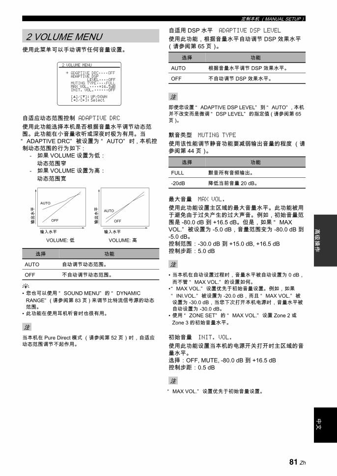
定制本机 (MANUAL SETUP)高
级操
作中
文
使用此菜单可以手动调节任何音量设置。
自适应动态范围控制 ADAPTIVE DRC使用此功能选择本机是否根据音量水平调节动态范围。此功能在小音量收听或深夜时极为有用。当“ ADAPTIVE DRC” 被设置为 “ AUTO” 时 , 本机控制动态范围的行为如下 :
- 如果 VOLUME 设置为低: 动态范围窄
- 如果 VOLUME 设置为高: 动态范围宽
y• 您也可以使用 “ SOUND MENU” 的 “ DYNAMIC
RANGE” ( 请参阅第 83 页 ) 来调节比特流信号源的动态范围。
• 此功能在使用耳机听音时也很有用。
当本机在 Pure Direct 模式 (请参阅第 52 页)时,自适应动态范围调节不起作用。
自适用 DSP 水平 ADAPTIVE DSP LEVEL
使用此功能,根据音量水平自动调节 DSP 效果水平(请参阅第 65 页)。
即使您设置 “ ADAPTIVE DSP LEVEL” 到 “ AUTO” , 本机并不改变而是微调 “ DSP LEVEL” 的指定值 ( 请参阅第 65页 )。
默音类型 MUTING TYPE
使用该性能调节静音功能要减弱输出音量的程度 (请参阅第 44 页)。
大音量 MAX VOL.
使用此功能设置主区域的 大音量水平。此功能被用于避免由于过失产生的过大声音。例如,初始音量范围是 -80.0 dB 到 +16.5 dB。但是,如果 “ MAX VOL.” 被设置为 -5.0 dB,音量范围变为 -80.0 dB 到 -5.0 dB。控制范围:-30.0 dB 到 +15.0 dB, +16.5 dB控制步距:5.0 dB
• 当本机在自动设置过程时,音量水平被自动设置为 0 dB,而不管 “ MAX VOL.” 的设置如何。
• “ MAX VOL.” 设置优先于初始音量设置。例如,如果“ INI.VOL.” 被设置为 -20.0 dB,而且 “ MAX VOL.” 被设置为 -30.0 dB,当您下次打开本机电源时,音量水平被自动设置为 -30.0 dB。
• 使用 “ ZONE SET” 的 “ MAX VOL.” 设置 Zone 2 或Zone 3 的初始音量水平。
初始音量 INIT. VOL.
使用此功能设置当本机的电源开关打开时主区域的音量水平。选择:OFF, MUTE, -80.0 dB 到 +16.5 dB控制步距:0.5 dB
“ MAX VOL.” 设置优先于初始音量设置。
2 VOLUME MENU
选择 功能
AUTO 自动调节动态范围。
OFF 不自动调节动态范围。
注
[]/[]:[p]/[[]:
[ p
2 VOLUME MENU
ADAPTIVE DRC;;;;OFFADAPTIVE DSP
LEVEL;;;;OFFMUTING TYPE;;;;FULLMAX VOL.;;;;+16.5dBINIT. VOL.;;;;;;OFF
UP/DOWNSelect
.
输入水平
输出
水平
输出
水平
输入水平
AUTO
OFF
AUTO
OFF
VOLUME: 低 VOLUME: 高
选择 功能
AUTO 根据音量水平调节 DSP 效果水平。
OFF 不自动调节 DSP 效果水平。
注
选择 功能
FULL 默音所有音频输出。
-20dB 降低当前音量 20 dB。
注
注
81 Zh

定制本机 (MANUAL SETUP)
用此功能调节音频参数。
均衡器 A)EQUALIZER
使用此特性选择参数均衡器或图形均衡器。
均衡器类型选择 EQ TYPE SELECT
使用该性能选择均衡器类型。
y当前使用的参数均衡器类型 (请参阅第 40 页)出现在“ AUTO PEQ” 下。
仅当您在高级配置 (请参阅第 37 页)进行 “ AUTO SETUP” 时,您可以选择 “ AUTO PEQ” 这时,“ AUTO PEQ” 被当作缺省设置自动选择。
可视均衡器 GEQ
用此功能来匹配前方左 / 右扬声器与中央,环绕声左 /右和后环绕声左 / 右,后环绕声和现场感左 / 右扬声器以及超低音扬声器的音调质量。您可以调节 7 频率波段 (63Hz, 160Hz, 400Hz, 1kHz, 2.5kHz, 6.3kHz, 16kHz)。控制范围:-6.0 dB 到 +6.0 dB控制步距:0.5 dB
y按下 3k / n,选择频率波段;按下 3l / h,调节选择的频率波段。
仅当在 “ EQ TYPE SELECT” 选择 “ GEQ” 时,“ GEQ”参数可以被调节。
测试音 TEST
当收听一个测试音调时,使用该性能进行 “ GEQ”的调节。要选择 “ TEST” ,在可视均衡器屏幕反复按下 3k / n。
3 SOUND MENU
选择 功能
AUTO PEQ 使用在 “ AUTO SETUP” 进行调节的参数均衡器 (请参阅第 37 页)
GEQ 调节内藏 7- 频率波段图形均衡器,使得扬声器的音调质量相互匹配。 按下3ENTER 显示可视均衡器屏幕。
OFF 取消均衡器功能。
注
[]/[]:[ENTER]:
[ p
3 SOUND MENU
A)EQUALIZERB)LFE LEVELC)DYNAMIC RANGED)LIPSYNCE)AUDIO SETF)HDMI SET
UP/DOWNEnter
.
[p]/[[]:[ENTER]:
A)EQUALIZER
EQ TYPE SELECT
AUTO PEQ >GEQ OFF[NATURAL]
SelectEnter
注
选择 功能
OFF 不输出测试音调,而输出当前选择的信号源装置。
ON 从选择的扬声器输出测试音调。
[]/[]:[p]/[[]:
[ p
A)EQUALIZER 1/2
TEST >OFF ONCHANNEL;;;;FRONT L
63Hz 0dB160Hz 0dB400Hz 0dB1kHz 0dB
UP/DOWNSelect
.
[]/[]:[p]/[[]:
[ p
A)EQUALIZER 2/2
TEST >OFF ONCHANNEL;;;;FRONT L
2.5kHz 0dB6.3kHz 0dB16kHz 0dB
UP/DOWNAdjust
.
[]/[]:[p]/[[]:
[ pA)EQUALIZER 1/2
TEST >OFF ONCHANNEL;;;;FRONT L
63Hz 0dB160Hz 0dB400Hz 0dB1kHz 0dB
UP/DOWNSelect
.
82 Zh

定制本机 (MANUAL SETUP)高
级操
作中
文
低频效果水平 B)LFE LEVEL使用该性能,根据您的超低音扬声器或耳机的能力,调节 LFE (低频效果)声道的输出水平。LFE 声道带有仅添加到特定场景的低频特殊效果。此设置仅在本机解码比特流信号时有效。控制范围:-20 到 0 dB控制步距:1 dB
扬声器 SPEAKER
调节扬声器 LFE 水平。
耳机 HEADPHONE
调节耳机 LFE 水平。
根据 “ LFE/BASS OUT” 的设置 ( 请参阅第 77 页 ),有些信号可能无法从 SUBWOOFER PRE OUT 插孔输出。
动态范围 C)DYNAMIC RANGE
使用该性能选择要用于您的扬声器或耳机的动态范围压缩量。此设置仅当本机在解码比特流信号时有效。
扬声器 SPEAKER
调节扬声器的动态范围压缩。
耳机 HEADPHONE
调节耳机的动态范围压缩。
注
[]/[]:[p]/[[]:
[ p
B)LFE LEVEL
SPEAKER;;;;;;0dBHEADPHONE;;;;0dB
UP/DOWNAdjust
.
选择 功能
MIN/AUTO • MIN: 在本机解码比特流信号时 (Dolby TrueHD 除外 ),调节动态范围到窄。
• AUTO: 本机解码 Dolby TrueHD 信号时,根据输入源信号的指示调节动态范围。
STD 调节动态范围到中。当本机解码 Dolby TrueHD 信号时,不管输入源信号的指示如何,动态范围控制总是激活状态。
MAX 保持 大的动态范围。
[]/[]:[p]/[[]:
[ p
C)DYNAMIC RANGE
SPEAKER;;;;;;;;;MAXHEADPHONE;;;;;;;MAX
UP/DOWNSelect
.
83 Zh
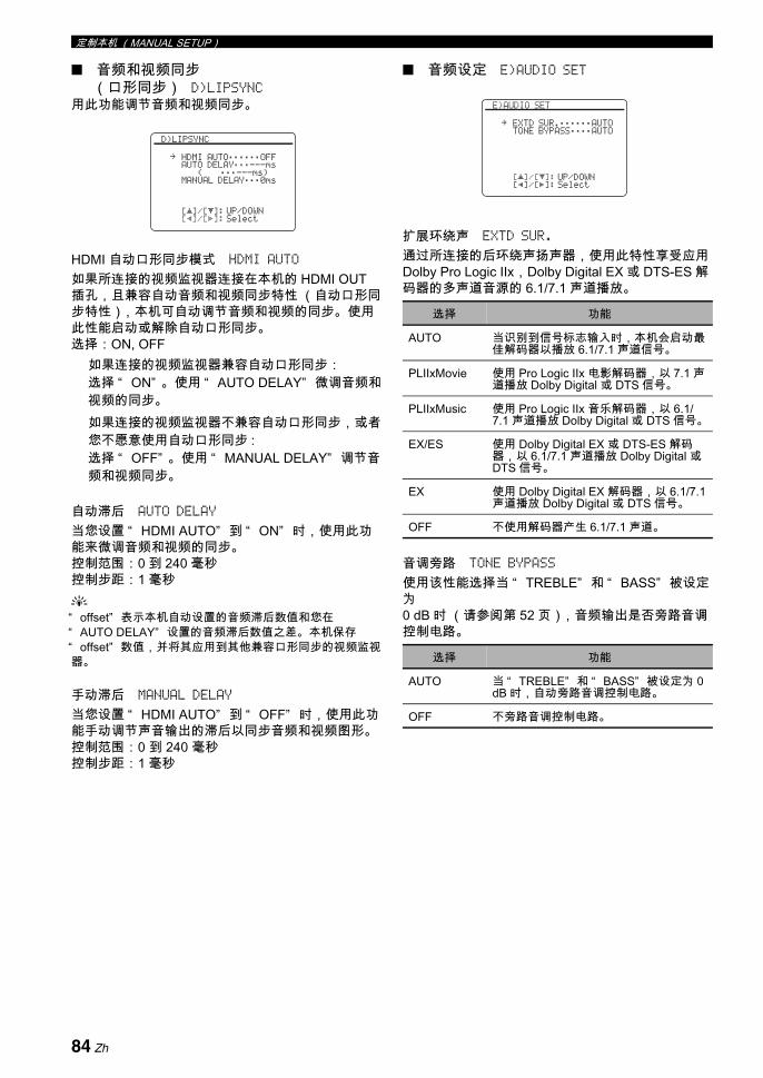
定制本机 (MANUAL SETUP)
音频和视频同步(口形同步) D)LIPSYNC
用此功能调节音频和视频同步。
HDMI 自动口形同步模式 HDMI AUTO
如果所连接的视频监视器连接在本机的 HDMI OUT插孔,且兼容自动音频和视频同步特性 (自动口形同步特性),本机可自动调节音频和视频的同步。使用此性能启动或解除自动口形同步。选择:ON, OFF
如果连接的视频监视器兼容自动口形同步:选择 “ ON” 。使用 “ AUTO DELAY” 微调音频和视频的同步。如果连接的视频监视器不兼容自动口形同步,或者您不愿意使用自动口形同步 :选择 “ OFF” 。使用 “ MANUAL DELAY” 调节音频和视频同步。
自动滞后 AUTO DELAY
当您设置 “ HDMI AUTO” 到 “ ON” 时,使用此功能来微调音频和视频的同步。控制范围:0 到 240 毫秒控制步距:1 毫秒y“ offset” 表示本机自动设置的音频滞后数值和您在“ AUTO DELAY” 设置的音频滞后数值之差。 本机保存“ offset” 数值,并将其应用到其他兼容口形同步的视频监视器。
手动滞后 MANUAL DELAY
当您设置 “ HDMI AUTO” 到 “ OFF” 时,使用此功能手动调节声音输出的滞后以同步音频和视频图形。控制范围:0 到 240 毫秒控制步距:1 毫秒
音频设定 E)AUDIO SET
扩展环绕声 EXTD SUR.
通过所连接的后环绕声扬声器,使用此特性享受应用Dolby Pro Logic IIx,Dolby Digital EX 或 DTS-ES 解码器的多声道音源的 6.1/7.1 声道播放。
音调旁路 TONE BYPASS
使用该性能选择当 “ TREBLE” 和 “ BASS” 被设定为0 dB 时 (请参阅第 52 页),音频输出是否旁路音调控制电路。
[]/[]:[p]/[[]:
[ p
D)LIPSYNC
HDMI AUTO;;;;;;OFFAUTO DELAY;;;---ms
(;;;---ms)MANUAL DELAY;;;0ms
UP/DOWNSelect
.
选择 功能
AUTO 当识别到信号标志输入时,本机会启动佳解码器以播放 6.1/7.1 声道信号。
PLIIxMovie 使用 Pro Logic IIx 电影解码器,以 7.1 声道播放 Dolby Digital 或 DTS 信号。
PLIIxMusic 使用 Pro Logic IIx 音乐解码器,以 6.1/7.1 声道播放 Dolby Digital 或 DTS 信号。
EX/ES 使用 Dolby Digital EX 或 DTS-ES 解码器,以 6.1/7.1 声道播放 Dolby Digital 或 DTS 信号。
EX 使用 Dolby Digital EX 解码器,以 6.1/7.1声道播放 Dolby Digital 或 DTS 信号。
OFF 不使用解码器产生 6.1/7.1 声道。
选择 功能
AUTO 当 “ TREBLE” 和 “ BASS” 被设定为 0 dB 时,自动旁路音调控制电路。
OFF 不旁路音调控制电路。
[]/[]:[p]/[[]:
[ p
E)AUDIO SET
EXTD SUR.;;;;;;AUTOTONE BYPASS;;;;AUTO
UP/DOWNSelect
.
84 Zh

定制本机 (MANUAL SETUP)高
级操
作中
文
HDMI 设置 F)HDMI SET使用该性能选择装置以播放 HDMI 音频信号。
支持音频 SUPPORT AUDIO
使用此功能选择是在本机播放 HDMI 音频信号,还是在连接在本机的后面板的 HDMI OUT 插孔上的其他HDMI 装置上播放。
• 即使当 “ SUPPORT AUDIO” 被设置为 “ OTHER” 时,本机也将来自 HDMI 输入插孔的视频信号传送到 HDMI 输出插孔。
• 可用的音频/视频信号取决于所连接的视频监视器的规格。 请参阅所连接的各装置的使用说明书。
用此菜单调节各个输入源的参数。
上面介绍的一些参数未必对所有输入源有用,某些参数只能用于特定的输入源。
选择 功能
RX-V1800 在本机播放 HDMI 音频信号。通过本机的HDMI 插孔输入的 HDMI 音频信号,不输出到连接在本机的后面板上的 HDMI OUT 插孔的 HDMI 装置。
OTHER 在另外的连接到 HDMI OUT 插孔的HDMI 装置播放 HDMI 音频信号。
注
[p]/[[]:[ENTER]:
F)HDMI SET
SUPPORT AUDIORX-V1800
SelectReturn
4 INPUT MENU
输入源 参数
A)TUNER INPUT RENAMEVOL. TRIM
B)MULTI CH INPUT RENAMEVOL. TRIMBGVINPUT CHFRONT
C)PHONOD)CDE)CD-RF)MD/TAPEG)BD/HD DVDH)DVDI)DTV/CBLJ)DVRK)VCRL)V-AUX
I/O ASSIGNMENTINPUT RENAMEVOL. TRIMDECODER MODE
M)DOCK INPUT RENAMEVOL. TRIMSTANDBY CHARGE
注
[]/[]:[ENTER]:
[ p
4 INPUT MENU 1/2
A) TUNERB) MULTI CHC) PHONOD) CDE) CD-RF) MD/TAPEG) BD/HD DVD
UP/DOWNEnter
.
[]/[]:[ENTER]:
[ p
4 INPUT MENU 2/2
H) DVDI) DTV/CBLJ) DVRK) VCRL) V-AUXM) DOCK
UP/DOWNEnter
.
85 Zh

定制本机 (MANUAL SETUP)
输入 / 输出分配 I/O ASSIGNMENT如果本机的初始设置不能适应您的需要,使用该性能根据所使用的组件机分配输入 / 输出插孔。改变参数以重新分配相应的插孔并有效地连接更多的组件机。一旦重新分配输入 / 输出插孔,您就能通过前面板上的C INPUT 选择器 (或遥控器上的输入选择器按钮)来选择对应的装置。
y• 当任何输入源没有分配到输入 / 输出插孔时,“ NONE” 出
现在 OSD 上。• 对于相同类型的插孔,您不能选择一个特定的项目一次以
上。• 工厂初始设置被改变的输入/输出插孔的名称左侧出现星号(*)。
• 为选择的输入 / 输出插孔所分配的当前输入源出现在 OSD(在以上的显示例子中 “ Current ( DTV/CBL )” )。
输入重命名 INPUT RENAME
使用此特性以改变 OSD 和前面板显示器上的输入源名称。
y您也可以改变出现在显示窗上的输入源的名称 (A)。请参考第 102 页上的 “ 在显示窗上改变源名称” 。
1 按下 3l / h,将“ _” ( 下划线 ) 置于您想要编辑的空格或字符之下。
2 按下 3k / n,选择您想要使用的字符,然后按下3l / h,移动到下一个空格。
• 对于每个输入,您能使用多达 9 个字符。• 按 3n 以按照下列的顺序改变下列的字符,或按3k 按照相反顺序改变 : A 到 Z, 0 到 9, a 到 z, 符号 ( #, *, -, +,等),空格。
3 重复步骤 1 到 2 以重新命名每个输入源。
4 按下 3ENTER,来完成。
音量修整 VOL. TRIM
使用此功能可以调节输入到各个插孔的信号的水平。 该功能有助于平衡各个输入源信号,从而避免在改变输入源时发生的音量突变。控制范围:-6.0 dB 到 +6.0 dB控制步距:0.5 dB初始设置:0.0 dB
y该参数也影响通过音频 ZONE OUT 插孔输出的信号。
解码器模式 DECODER MODE
本功能用于切换解码器模式。您可以为 DTS 信号指定再分配的数码输入插孔。
[p]/[[]:[ENTER]:
J) DVR
COMPONENT IN;;;[C]*COAXIAL IN;;;;;(3)OPTICAL IN;;;;NONEOPTICAL OUT;;;NONEHDMI IN;;;;;;;;[4]
Current ( DTV/CBL )SelectEnter
.
[p]/[[]:[ ]/[ ]:[ENTER]:
[RETURN]:
[ p
A) TUNER
INPUT RENAME
TUNER . TUNER
PositionCharacterEnterReturn
注
选择 功能
AUTO 自动检测数码音频信号类型并选择妥当的解码器。
DTS 当数码音频信号输入时启动 DTS 解码器。
[]/[]:[p]/[[]:
[ p
A) TUNER
INPUT RENAMEVOL. TRIM;;;;+6.0dB
UP/DOWNAdjust
.
[]/[]:[p]/[[]:
[ p
D) CD
I/O ASSIGNMENTINPUT RENAMEVOL. TRIM;;;;;0.0dBDECODER MODE;;;AUTO
UP/DOWNSelect
.
86 Zh

定制本机 (MANUAL SETUP)高
级操
作中
文
在待机时充电 STANDBY CHARGE
当本机处于待机模式时,使用该性能选择本机驳接的iPod 的电池充电与否 (请参阅第 61 页)。
多声道输入 BGV BGV
使用此功能选择在 MULTI CH INPUT 插孔输入的音源的背景里播放的视频源。
输入声道 INPUT CH
该设定用于选择从外部解码器输入声道数 ( 请参阅第30 页 )。选择 : 6CH, 8CH
如果连接的装置输出分离的 6- 声道音频信号:选择 “ 6CH” 。如果连接的装置输出分离的 8- 声道音频信号:选择 “ 8CH” 。也设置 “ FRONT” ( 参阅下文 )到模拟音频插孔,在此插孔上来自外部解码器的前方左右声道信号输入。
如果 “ AMP” 被设置到 “ [SP1]” , “ [SP2]” 或 “ BOTH”(请参阅第 91 页),即使您选择 “ 8CH” ,也没有声音从后环绕声扬声器输出。在这种情况下,选择 “ 6CH” ,将外部装置的输出设置为 6 声道。
前方左右声道输入插孔 FRONT
如果您在 “ INPUT CH” 选择 “ 8CH” , 您可以选择模拟音频插孔作为来自外部解码器的前方左右声道信号的输入插孔。选择:CD, CD-R, MD/TAPE, BD/HD DVD, DVD,
DTV/CBL, VCR, DVR, V-AUX
仅当您设置 “ INPUT CH” 到 “ 8CH” 时,“ FRONT” 参数出现。
选择 功能
AUTO 当本机打开并处于待机模式时,为本机驳接的 iPod 的电池充电。
OFF 仅当本机打开时,为本机驳接的 iPod 的电池充电。
选择 功能
LAST 自动选择 后选择的视频源当作背景视频源。
BD/HD DVD, DTV/CBL, DVD, DVR, VCR, V-AUX
选择对应的输入源当作背景视频源。
OFF 不在背景中播放视频源。
[]/[]:[ENTER]:
[ p
B) MULTI CH
INPUT RENAMEVOL. TRIM;;;;;0.0dBBGV;;;;;;;;;;;;LASTINPUT CH;;;;;;;;6CH
UP/DOWNSelect
.
注
注
[]/[]:[ENTER]:
[ p
B) MULTI CH
INPUT RENAMEVOL. TRIM;;;;;0.0dBBGV;;;;;;;;;;;;LASTINPUT CH;;;;;;;;6CH
UP/DOWNSelect
.
[]/[]:[ENTER]:
[ p
B) MULTI CH
INPUT RENAMEVOL. TRIM;;;;;0.0dBBGV;;;;;;;;;;;;LASTINPUT CH;;;;;;;;8CHFRONT;;;;;BD/HD DVD
UP/DOWNSelect
.
87 Zh
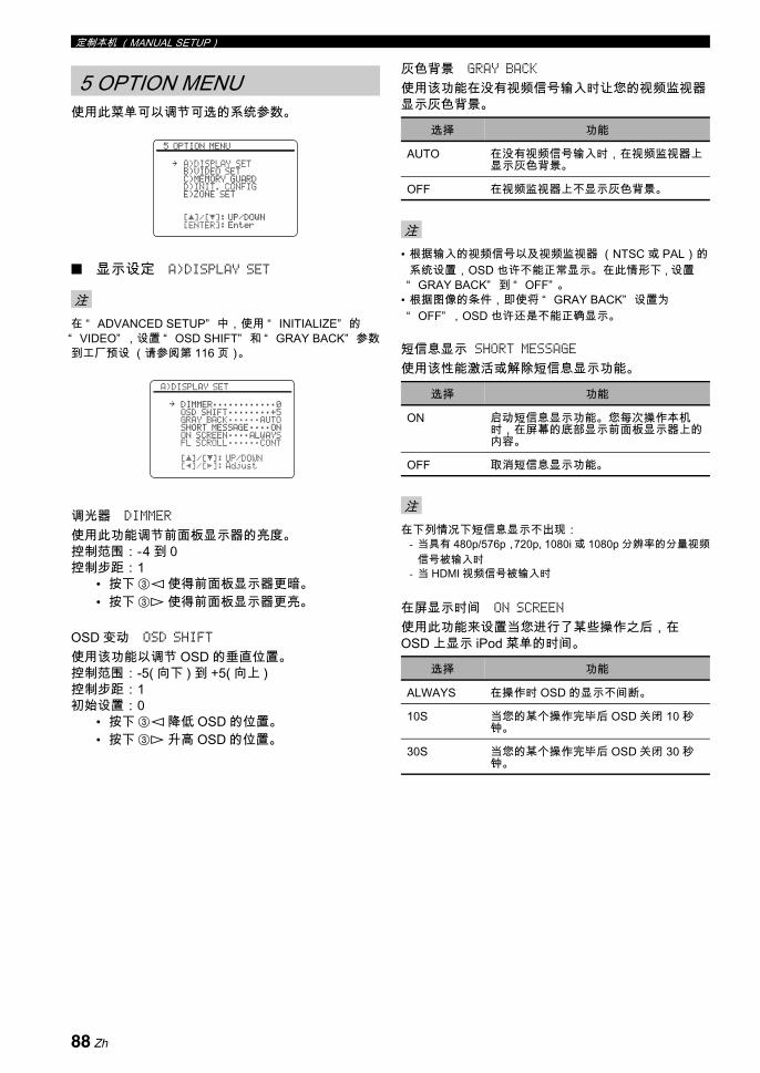
定制本机 (MANUAL SETUP)
使用此菜单可以调节可选的系统参数。
显示设定 A)DISPLAY SET
在 “ ADVANCED SETUP” 中,使用 “ INITIALIZE” 的“ VIDEO” ,设置 “ OSD SHIFT” 和 “ GRAY BACK” 参数到工厂预设 (请参阅第 116 页)。
调光器 DIMMER
使用此功能调节前面板显示器的亮度。控制范围:-4 到 0控制步距:1
• 按下 3l 使得前面板显示器更暗。• 按下 3h 使得前面板显示器更亮。
OSD 变动 OSD SHIFT
使用该功能以调节 OSD 的垂直位置。控制范围:-5( 向下 ) 到 +5( 向上 )控制步距:1初始设置:0
• 按下 3l 降低 OSD 的位置。• 按下 3h 升高 OSD 的位置。
灰色背景 GRAY BACK
使用该功能在没有视频信号输入时让您的视频监视器显示灰色背景。
• 根据输入的视频信号以及视频监视器 (NTSC 或 PAL)的系统设置,OSD 也许不能正常显示。在此情形下 , 设置“ GRAY BACK” 到 “ OFF” 。
• 根据图像的条件,即使将 “ GRAY BACK” 设置为“ OFF” ,OSD 也许还是不能正确显示。
短信息显示 SHORT MESSAGE使用该性能激活或解除短信息显示功能。
在下列情况下短信息显示不出现:- 当具有 480p/576p,720p, 1080i 或 1080p 分辨率的分量视频
信号被输入时- 当 HDMI 视频信号被输入时
在屏显示时间 ON SCREEN
使用此功能来设置当您进行了某些操作之后,在OSD 上显示 iPod 菜单的时间。
5 OPTION MENU
注
[]/[]:[ENTER]:
[ p
5 OPTION MENU
A)DISPLAY SETB)VIDEO SETC)MEMORY GUARDD)INIT. CONFIGE)ZONE SET
UP/DOWNEnter
.
[]/[]:[p]/[[]:
[ p
A)DISPLAY SET
DIMMER;;;;;;;;;;;;0OSD SHIFT;;;;;;;;+5GRAY BACK;;;;;;AUTOSHORT MESSAGE;;;;ONON SCREEN;;;;ALWAYSFL SCROLL;;;;;;CONT
UP/DOWNAdjust
.
选择 功能
AUTO 在没有视频信号输入时,在视频监视器上显示灰色背景。
OFF 在视频监视器上不显示灰色背景。
注
选择 功能
ON 启动短信息显示功能。您每次操作本机时,在屏幕的底部显示前面板显示器上的内容。
OFF 取消短信息显示功能。
注
选择 功能
ALWAYS 在操作时 OSD 的显示不间断。
10S 当您的某个操作完毕后 OSD 关闭 10 秒钟。
30S 当您的某个操作完毕后 OSD 关闭 30 秒钟。
88 Zh

定制本机 (MANUAL SETUP)高
级操
作中
文
前面板显示器滚动 FL SCROLL
使用此功能以设置模式,在前面板显示器上显示 iPod菜单 (比如歌曲名称或声道名称)。
视频设置 B)VIDEO SET
视频转换 VIDEO CONV.
使用该功能设置是否转换通过 VIDEO,S VIDEO 和COMPONENT VIDEO 插孔输入的视频信号。
• 本机不能交替转换 480 线视频信号和 576 线视频信号。• 具有分辨率为480i (NTSC)/576i (PAL)的模拟分量视频信号
可以被转换到 S 视频或复合视频信号,并通过 S VIDEO MONITOR OUT 和 VIDEO MONITOR OUT 插孔输出。
• 具有1080p分辨率的视频信号仅通过本机的COMPONENT VIDEO MONITOR OUT 插孔输出。
• 转换后的视频信号仅输出到 MONITOR OUT 插孔。录制视频源时,您必须在每个组件机之间进行同类的视频连接。
• 当转换来自录像机的复合视频或 S 视频信号到分量视频信号时,根据您的录像机的情况,图像质量可能会受影响。
• 设置 “ VIDEO CONV.” 到 “ ON” 以显示声场参数和短信息显示。
• 从复合视频或 S 视频插孔输入的非常规信号不能转换或者出现输出异常。在此情形下 , 设置 “ VIDEO CONV.” 到“ OFF” 。
分量隔行扫描 / 逐行扫描内部转换 COMPONENT I/P
使用该性能激活或解除通过组合视频,S- 视频和分量视频插孔输入的模拟视频信号的模拟隔行扫描 / 逐行扫描转换,从 480i (NTSC) / 576i (PAL) 到 480p / 576p 得到的非隔行模拟视频信号通过 COMPONENT MONITOR OUT 插孔输出。
• 仅当您设置 “ VIDEO CONV.” 到 “ ON” 时,“ COMPONENT I/P” 参数出现。
• 当 “ COMPONENT I/P” 设置到 “ ON” 时,如果您的视频监视器不支持分辨率为 480p/576p 的模拟视频信号,在您的视频监视器上也许不能显示 SET MENU 项目。在此情形下,设置 “ COMPONENT I/P” 参数为 “ OFF” 。
HDMI 缩放 HDMI SCALING
使用此功能启动或取消 HDMI 的模拟视频信号提升;提升可以将 VIDEO, S VIDEO 和 COMPONENT VIDEO 插孔输入的模拟视频信号转换,提升后的视频信号在 HDMI OUT 插孔输出。本机提升的视频信号如下所示:
• 480i(NTSC)/576i(PAL)→ 480p/576p, 1080i, 720p 或 1080p
• 480p/576p → 1080i, 720p 或 1080p
本机不提升 720p 或 1080i 分辨率的模拟分量视频信号。
选择 功能
CONT 连续模式。选择此项,在前面板显示器上连续显示操作状态。
ONCE 翻卷一次模式。选择此项,在前面板显示器上滚动显示操作状态完毕后,显示 初的 14 个字符。
选择 功能
ON 转换复合视频,S 视频信号和分量视频信号以及向上转换复合视频,S 视频和分量视频信号到 HDMI 视频信号。
OFF 不转换任何信号。
注
[]/[]:[p]/[[]:
[ p
B)VIDEO SET
VIDEO CONV.;;;;;;ONCOMPONENT I/P;;;OFFHDMI SCALING;;;480pHDMI ASPECT;;;THRGH
UP/DOWNSelect
.
选择 功能
ON 启动模拟视频信号的模拟隔行扫描 / 逐行扫描内部转换。
OFF 取消模拟视频信号的模拟隔行扫描 / 逐行扫描内部转换。
注
选择 功能
THROUGH 不对模拟视频信号进行提升。
480p ( 或 576p), 1080i, 720p, 1080p
提升模拟视频信号到 480p 或 576p, 1080i, 720p, 或 1080p 的分辨率。
注
89 Zh
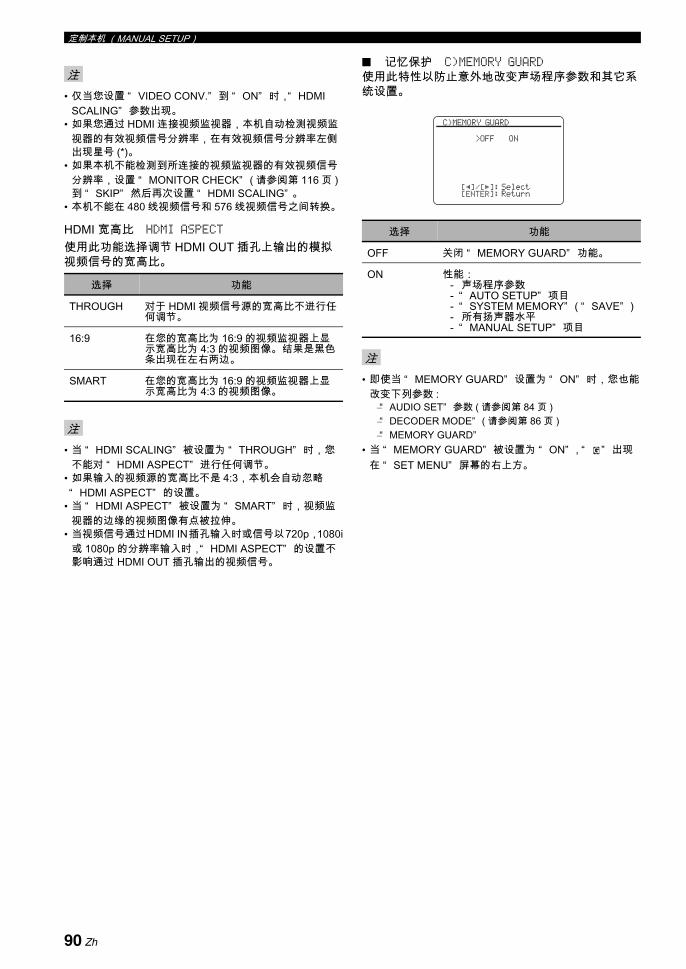
定制本机 (MANUAL SETUP)
• 仅当您设置 “ VIDEO CONV.” 到 “ ON” 时,“ HDMI SCALING” 参数出现。
• 如果您通过 HDMI 连接视频监视器,本机自动检测视频监视器的有效视频信号分辨率,在有效视频信号分辨率左侧出现星号 (*)。
• 如果本机不能检测到所连接的视频监视器的有效视频信号分辨率,设置 “ MONITOR CHECK” ( 请参阅第 116 页 )到 “ SKIP” 然后再次设置 “ HDMI SCALING” 。
• 本机不能在 480 线视频信号和 576 线视频信号之间转换。
HDMI 宽高比 HDMI ASPECT
使用此功能选择调节 HDMI OUT 插孔上输出的模拟视频信号的宽高比。
• 当 “ HDMI SCALING” 被设置为 “ THROUGH” 时,您不能对 “ HDMI ASPECT” 进行任何调节。
• 如果输入的视频源的宽高比不是 4:3,本机会自动忽略“ HDMI ASPECT” 的设置。
• 当 “ HDMI ASPECT” 被设置为 “ SMART” 时,视频监视器的边缘的视频图像有点被拉伸。
• 当视频信号通过HDMI IN插孔输入时或信号以720p,1080i或 1080p 的分辨率输入时,“ HDMI ASPECT” 的设置不影响通过 HDMI OUT 插孔输出的视频信号。
记忆保护 C)MEMORY GUARD使用此特性以防止意外地改变声场程序参数和其它系统设置。
• 即使当 “ MEMORY GUARD” 设置为 “ ON” 时,您也能改变下列参数 :
–“ AUDIO SET” 参数 ( 请参阅第 84 页 )–“ DECODER MODE” ( 请参阅第 86 页 )–“ MEMORY GUARD”
• 当 “ MEMORY GUARD” 被设置为 “ ON” , “ ” 出现在 “ SET MENU” 屏幕的右上方。
注
选择 功能
THROUGH 对于 HDMI 视频信号源的宽高比不进行任何调节。
16:9 在您的宽高比为 16:9 的视频监视器上显示宽高比为 4:3 的视频图像。 结果是黑色条出现在左右两边。
SMART 在您的宽高比为 16:9 的视频监视器上显示宽高比为 4:3 的视频图像。
注
选择 功能
OFF 关闭 “ MEMORY GUARD” 功能。
ON 性能:- 声场程序参数- “ AUTO SETUP” 项目- “ SYSTEM MEMORY” ( “ SAVE” )- 所有扬声器水平- “ MANUAL SETUP” 项目
注
[p]/[[]:[ENTER]:
C)MEMORY GUARD
>OFF ON
SelectReturn
G
90 Zh

定制本机 (MANUAL SETUP)高
级操
作中
文
初始配置 D)INIT. CONFIG使用此功能选择音频输入插孔选择的设置,当您打开本机时启动解码器和扩展环绕声。
音频选择 AUDIO SELECT
使用此功能指定打开本机电源时,连接在 DIGITAL INPUT 插孔上的输入源的缺省音频输入插孔选择的设置 (请参阅第 43 页)。
解码器模式 DECODER MODE
使用该性能指定打开本机电源时连接到 DIGITAL INPUT 插孔的输入源的缺省解码器模式 (请参阅第86 页)。
扩展环绕声 EXTD SUR.
使用该性能指定打开本机电源时连接到 DIGITAL INPUT 插孔的输入源的扩展解码器模式 (请参阅第84 页)。
区域设置 E)ZONE SET
使用此功能设置 Zone 2 或 Zone 3 的有关项目。
设置区域选择区域,设置 “ AMP” , “ VOLUME” , “ MAX VOL.” 和 “ INIT. VOL.” 。
Zone 2/Zone 3 放大器 AMP
用此功能选择 Zone 2 或 Zone 3 扬声器如何放大。 此参数也影响主区域的扬声器设置以及声场程序的音响输出。选择:EXT, [SP1], [SP2], BOTH
当 Zone 2 或 Zone 3 的扬声器被连接到外部放大器,且外部放大器连接到本机的 ZONE OUT (ZONE 2 或 ZONE 3) 插孔 :选择 “ EXT” 。 有关详情请参阅第 108 页上的“ 使用外部放大器” 。
当在 “ ADVANCED SETUP” 中的 “ BI-AMP” 设置为“ ON” (请参阅第 116 页)时,您只能在 “ ZONE 2”或 “ ZONE 3” 中设置 “ AMP” 到 “ EXT” 。
当 Zone 2 或 Zone 3 的扬声器被直接连接到本机的 SP1 扬声器端子时:选择 “ [SP1]” 。 有关详情请参阅第 109 页上的“ 使用本机的内部放大器” 。
当您在 “ ZONE 2” 或 “ ZONE 3” 中设置 “ AMP” 到“ [SP1]” ,并且打开相应的区域,没有声音从后环绕声扬声器输出。
选择 功能
AUTO 自动检测音频输入信号类型并选择妥当的音频输入插孔选择设置。
LAST 自动选择用于连接输入源的 后的音频输入插孔选择设置。
选择 功能
AUTO 自动检测输入信号类型并选择妥当的解码器模式设置。
LAST 自动选择用于所连接输入源的 后解码器模式设置。
选择 功能
AUTO 自动检测数码音频输入信号类型并启动妥当的解码器。
LAST 为 “ SOUND MENU” 的 “ EXTD SUR.” 自动选择 后的解码器模式设置。
[p]/[[]:[ENTER]:
D)INIT. CONFIG
AUDIO SELECT;;AUTODECODER MODE;;AUTOEXTD SUR.;;;;;AUTO
SelectReturn
.
选择 功能
ZONE2 为 Zone 2 设置 “ ZONE SET” 参数。
ZONE3 为 Zone 3 设置 “ ZONE SET” 参数。
注
注
[]/[]:[p]/[[]:
[ p
E)ZONE SET
>ZONE2 ZONE3
AMP;;;;;;;;;;;;EXTVOLUME;;;;;;;;;VARMAX VOL.;;;-30.0dBINIT. VOL.;+16.5dB
UP/DOWNSelect
.
91 Zh
定制本机 (MANUAL SETUP)
当 Zone 2 或 Zone 3 的扬声器被直接连接到本机的 SP2 扬声器端子时:选择 “ [SP2]” 。有关详情请参阅第 109 页上的“ 使用本机的内部放大器” 。
当您在 “ ZONE 2” 或 “ ZONE 3” 中设置 “ AMP” 到“ [SP2]” ,并且打开相应的区域,没有声音从环绕声扬声器输出。
如果 Zone 2 或 Zone 3 的扬声器被同时连接到SP1 和 SP2 扬声器端子 ( 比如,扬声器通过双重放大器连接,或者房间内有 4 个扬声器 ), 或者如果您想在 Zone 2 和 Zone 3 同时播放相同的音源 :选择 “ BOTH” 。有关详情请参阅第 109 页上的“ 使用本机的内部放大器” 。
• 当您在 “ ZONE 2” 或 “ ZONE 3” 中设置 “ AMP”到 “ BOTH” 时,您只能在其他区域设置中设置“ AMP” 到 “ EXT” 。
• 当您在 “ ZONE 2” 或 “ ZONE 3” 中设置 “ AMP”到 “ BOTH” ,并且打开相应的区域,没有声音从环绕声和后环绕声扬声器双方输出。
Zone 2/Zone 3 音量 VOLUME
使用此功能来选择,当您设置 “ AMP” 到 “ EXT” (请参阅第 91 页 ) 时,本机是否控制在 ZONE OUT(ZONE 2 或 ZONE 3)插孔输出的音频信号的音量水平。选择:VAR, FIX
当您期望在本机上控制所选择区域的音量时:选择 “ VAR” 。使用遥控器上的 BVOLUME +/-,您可以同时调节 ZONE OUT (ZONE 2 或 ZONE 3)的音量。
当您期望在外部放大器上控制选择的区域的音量水平时:选择 “ FIX” 。本机固定 ZONE OUT (ZONE 2 或ZONE 3)的音量水平到一个标准线水平。
Zone 2/Zone 3 大音量 MAX VOL.
使用此功能设置 Zone 2 或 Zone 3 的 大音量水平。控制范围:-30.0 dB 到 +15.0 dB, +16.5 dB控制步距:5.0 dB
“ MAX VOL.” 设置优先于 “ INIT. VOL.” 设置。 例如,“ INIT. VOL.” 被设置为 -20.0 dB,而且 “ MAX VOL.” 被设置为 -30.0 dB,当您下次打开本机电源时,音量水平被自动设置为 -30.0 dB。
Zone 2/Zone 3 初始音量 INIT. VOL.
使用此功能设置当 Zone 2 或 Zone 3 的电源开关打开时,Zone 2 或 Zone 3 的音量水平。选择:OFF, MUTE, -80.0 dB 到 +16.5 dB控制步距:0.5 dB
“ MAX VOL.” 设置优先于 “ INIT. VOL.” 设置。
注
注
注
注
92 Zh
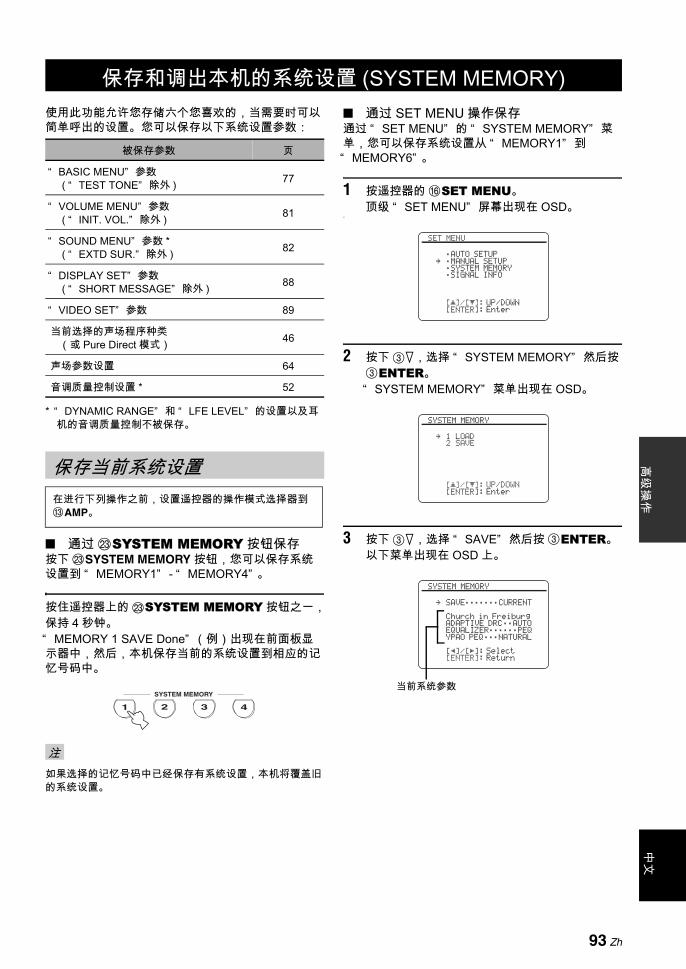
中文
高级
操作
使用此功能允许您存储六个您喜欢的,当需要时可以简单呼出的设置。您可以保存以下系统设置参数:
* “ DYNAMIC RANGE” 和 “ LFE LEVEL” 的设置以及耳机的音调质量控制不被保存。
通过 MSYSTEM MEMORY 按钮保存按下 MSYSTEM MEMORY 按钮,您可以保存系统设置到 “ MEMORY1” - “ MEMORY4” 。
按住遥控器上的 MSYSTEM MEMORY 按钮之一,保持 4 秒钟。“ MEMORY 1 SAVE Done” (例)出现在前面板显示器中,然后,本机保存当前的系统设置到相应的记忆号码中。
如果选择的记忆号码中已经保存有系统设置,本机将覆盖旧的系统设置。
通过 SET MENU 操作保存通过 “ SET MENU” 的 “ SYSTEM MEMORY” 菜单,您可以保存系统设置从 “ MEMORY1” 到“ MEMORY6” 。
1 按遥控器的 FSET MENU。顶级 “ SET MENU” 屏幕出现在 OSD。
o
2 按下 3n,选择 “ SYSTEM MEMORY” 然后按3ENTER。“ SYSTEM MEMORY” 菜单出现在 OSD。
3 按下 3n,选择 “ SAVE” 然后按 3ENTER。以下菜单出现在 OSD 上。
保存和调出本机的系统设置 (SYSTEM MEMORY)
被保存参数 页
“ BASIC MENU” 参数( “ TEST TONE” 除外 ) 77
“ VOLUME MENU” 参数( “ INIT. VOL.” 除外 ) 81
“ SOUND MENU” 参数 *( “ EXTD SUR.” 除外 ) 82
“ DISPLAY SET” 参数( “ SHORT MESSAGE” 除外 ) 88
“ VIDEO SET” 参数 89
当前选择的声场程序种类(或 Pure Direct 模式) 46
声场参数设置 64
音调质量控制设置 * 52
保存当前系统设置在进行下列操作之前,设置遥控器的操作模式选择器到CAMP。
注
4321
SYSTEM MEMORY
[]/[]:[ENTER]:
[ p
SET MENU
;AUTO SETUP;MANUAL SETUP;SYSTEM MEMORY;SIGNAL INFO
UP/DOWNEnter
.
[]/[]:[ENTER]:
[ p
SYSTEM MEMORY
1 LOAD2 SAVE
UP/DOWNEnter
.
[p]/[[]:[ENTER]:
SYSTEM MEMORY
SAVE;;;;;;;CURRENT
Church in FreiburgADAPTIVE DRC;;AUTOEQUALIZER;;;;;;PEQYPAO PEQ;;;NATURAL
SelectReturn
.
当前系统参数
93 Zh

保存和调出本机的系统设置 (SYSTEM MEMORY)
4 反复按下 3l / h 选择期望的记忆号码 (“ MEMORY1” - “ MEMORY6” )。
y• 如果系统设置保存在选择的记忆号码中,则保存的系
统参数设置出现在菜单屏幕。如果没有系统设置保存在选择的记忆号码中,则 “ EMPTY” 出现在菜单屏幕。
• 如果选择的记忆号码中已经保存有系统设置,本机将覆盖旧的系统设置。
• 如果您保存系统设置到 “ MEMORY1” -“ MEMORY4” ,通过按下对应的 MSYSTEM MEMORY 按钮,您可以装载保存的设置 ( 请参阅第 94页 )。
5 按下 3ENTER 保存当前系统设置到选择的记忆号码。
6 再次按下 FSET MENU,退出 “ SET MENU” 。
通过 MSYSTEM MEMORY 按钮装载按下 MSYSTEM MEMORY 按钮,您可以呼出保存在 “ MEMORY1” - “ MEMORY4” 的系统设置。
1 按下遥控器的 MSYSTEM MEMORY 按钮之一,选择期望的记忆号码。“ MEMORY 1 LOAD” (例)出现在前面板显示器中。
y如果没有系统设置保存在选择的记忆号码中,则“ EMPTY” 出现在菜单屏幕。
2 再次按下 MSYSTEM MEMORY 按钮,确认选择。本机装载选择的记忆号码中保存系统参数。
通过 SET MENU 操作装载
1 按遥控器的 FSET MENU。顶级 “ SET MENU” 屏幕出现在 OSD。
2 按下 3n,选择 “ SYSTEM MEMORY” 然后按下 3ENTER。“ SYSTEM MEMORY” 菜单出现在 OSD。
3 按 3ENTER 选择 “ LOAD” 。以下菜单出现在 OSD 上。
4 反复按下 3l / h,选择期望的,保存有系统设置的记忆号码 , 然后按下 3ENTER。本机装载选择的系统设置。
5 按 FSET MENU 以退出 “ SET MENU” 。
装载保存的系统设置• 在进行下列操作之前,设置遥控器的操作模式选择器
到 CAMP。• 本机使用保存的设置覆盖掉本机的当前设置。如果您
不期望删除当前设置,首先将当前设置保存到任一个SYSTEM MEMORY 号码。
[p]/[[]:[ENTER]:
SYSTEM MEMORY
SAVE;;;;;;;MEMORY1
DramaADAPTIVE DRC;;AUTOEQUALIZER;;;;;;GEQYPAO PEQ;;;;;;NONE
SelectReturn
.
在选择的记忆号码中保存系统参数
4321
SYSTEM MEMORY
[p]/[[]:[ENTER]:
SYSTEM MEMORY
LOAD;;;;;;;CURRENT
Church in FreiburgADAPTIVE DRC;;AUTOEQUALIZER;;;;;;PEQYPAO PEQ;;;NATURAL
SelectReturn
.
[p]/[[]:[ENTER]:
SYSTEM MEMORY
LOAD;;;;;;;MEMORY6
StraightADAPTIVE DRC;;AUTOEQUALIZER;;;;;;PEQYPAO PEQ;;;;;;FLAT
SelectLoad
.
94 Zh

保存和调出本机的系统设置 (SYSTEM MEMORY)高
级操
作中
文
例 1:比较自动设置和手动设置的结果本机具备三种类型的参数均衡器设置 ( 请参阅第 40页 ),此外,使用 “ MANUAL SETUP” 参数 ( 请参阅第 72 页 ),您还可以在本机进行音响设置的定做配置。 要比较自动设置和手动设置的结果,使用MSYSTEM MEMORY 按钮。
保存各设置
当所有参数设置为默认值时,进行以下操作。
1 按住 MSYSTEM MEMORY 1 大约 4 秒钟。本机保存当前设置到 “ MEMORY1” 。
2 进行自动设置。设置 “ EQ” 为 “ NATURAL” 。有关详情请参阅第 40 页。
3 按住 MSYSTEM MEMORY 2 大约 4 秒钟。本机保存步骤 2 进行的自动设置的结果到“ MEMORY2” 。
4 再次进行自动设置。此次,设置 “ EQ” 为 “ FRONT” 。
5 按住 MSYSTEM MEMORY 3 大约 4 秒钟。本机保存步骤 4 进行的自动设置的结果到“ MEMORY3” 。
例 2:为不同的室内环境切换设置室内的音调特性会因为室内环境 (例如,窗帘的开闭等)而变,所以,本机的设置也必须根据室内的状况进行。使用 MSYSTEM MEMORY 按钮,您可以方便地在本机的各种设置间切换。
保存各设置
1 关闭听音室窗帘然后进行自动设置。自动设置的详情,请参阅第 37 页。
2 按住 MSYSTEM MEMORY 1 大约 4 秒钟。本机保存为当前室内环境 (即,窗帘关闭时)进行的设置到 “ MEMORY1” 。
3 开启听音室窗帘然后进行自动设置。
4 按住 MSYSTEM MEMORY 2 大约 4 秒钟。本机保存为当前室内环境 (即,窗帘开启时)进行的设置到 “ MEMORY2” 。
用例
注
4
5 76 8
CLASSICAL LIVE/CLUB ENTERTAIN MOVIE
SYSTEM MEMORY
321
SYSTEM MEMORY 1本机的当前设置
SYSTEM MEMORY 2自动设置的结果 (EQ: NATURAL)
SYSTEM MEMORY 3自动设置的结果 (EQ: FRONT)
4
5 76 8
CLASSICAL LIVE/CLUB ENTERTAIN MOVIE
SYSTEM MEMORY
321
SYSTEM MEMORY 1当听音室的窗帘关闭时的设置
SYSTEM MEMORY 2当听音室的窗帘开启时的设置
95 Zh

保存和调出本机的系统设置 (SYSTEM MEMORY)
例 3:保存用于特别输入源的音响配置对于不同的输入源,期望的音响配置也不同。例如,如果您对生动的爵士乐表演使用 “ Village Vanguard” 声场程序,参数的设置当然与输入源来自塑料唱片或 SACD 时不同。您可以为不同的输入源保存各自的音响配置。
保存各设置y有关声场程序参数设置,请参阅第 64 页。
1 开始播放录制在 SACD 上的期望的爵士乐表演。
2 设置声场程序到 “ Village Vanguard” ,然后为当前播放音源调节参数。
3 按住 MSYSTEM MEMORY 1 大约 4 秒钟。本机保存当前的声场程序设置到“ MEMORY1” 。
4 改变输入源到 “ PHONO” ,然后开始播放录制在塑料唱片上的爵士乐表演。
5 为当前播放的音源调节声场程序参数。
6 按住 MSYSTEM MEMORY 2 大约 4 秒钟。本机保存当前的声场程序设置到“ MEMORY2” 。
例 4:切换多个音频和视频同步设置如果您使用两种不同的视频监视器或投影仪,而这些装置不兼容自动音频和视频同步功能,您必须为各装置设置 “ MANUAL DELAY” 。使用 MSYSTEM MEMORY 按钮,您可以在各种 “ MANUAL DELAY”设置间切换。
保存各设置
下例中,LCD 视频监视器和另一个输入装置 ( 比如 VCR) 连接在 S VIDEO 输入插孔和 S VIDEO MONITOR OUT 插孔,而视频投影仪和另一个输入装置 ( 比如 DVD 播放机 ) 分别连接在 HDMI IN 插孔和 HDMI OUT 插孔。
1 在所连接的 LCD 视频监视器上开始播放期望的视频源,然后调节 “ SOUND MENU” 的“ MANUAL DELAY” (请参阅第 84 页)。
2 按住 MSYSTEM MEMORY 1 大约 4 秒钟。本机保存用于 LCD 视频监视器的音频和视频同步设置到 “ MEMORY 1” 。
3 改变输入源到连接在 HDMI IN 插孔之一上的装置并开始播放。
4 妥当调节 “ SOUND MENU” 的 “ MANUAL DELAY” 设置。
5 按住 MSYSTEM MEMORY 2 大约 4 秒钟。本机保存用于视频投影仪的音频和视频同步设置到 “ MEMORY 2” 。
4
5 76 8
CLASSICAL LIVE/CLUB ENTERTAIN MOVIE
SYSTEM MEMORY
321
SYSTEM MEMORY 1用于 SACD 输入源的 “ Village Vanguard” 程序配置
SYSTEM MEMORY 2用于塑料唱片输入源的 “ Village Vanguard”程序配置
注
4
5 76 8
CLASSICAL LIVE/CLUB ENTERTAIN MOVIE
SYSTEM MEMORY
321
SYSTEM MEMORY 1用于连接在 S VIDEO MONITOR OUT 插孔的 LCD 视频监视器的设置
SYSTEM MEMORY 2用于连接在 HDMI OUT 插孔的视频投影仪的设置
96 Zh

中文
高级
操作
除了控制本机之外,此遥控器还能操作其它的由 Yamaha 和其它厂商制造的视听组件机。要操作您的电视机或其他组件机时,您必须为各个输入源设置妥当的遥控器代码 (请参阅第 99 页)。
控制本机设置操作模式选择开关到 CAMP 以操作本机。
*1 不管操作模式选择开关的位置如何,这些按钮总是操作本机。
*2 只有当该装置操作模式选择开关设置为 CAMP 时,这些按钮才能操作本机。
操作电视机设置操作模式选择开关到 CTV 以操作您的电视机。 要操作您的电视机,您必须事先为 DTV/CBL 或PHONO 设置妥当的遥控器代码 (请参阅第 99 页)。当您为 DTV 和 PHONO 双方设置遥控代码时,为DTV 设置的优先。
*1 不管操作模式选择开关的位置如何,这些按钮总是操作您的电视机。
*2 只有当操作模式选择开关设置为 CTV 时,这些按钮才能操作您的电视机。有关详情,请参阅第 98 页上的
TV”
遥控器功能
操作本机,电视机,或其他组件机
注
–
+ +
––
+
ENTER
DISPLAY
AUDIO
MENUTITLE
TV MUTE TV INPUT MUTE
432
ENT+1009
5
1
AVTV
76 8
RETURN
ONOFF CLEARLEARN RENAMEMACRO
REC
DISC SKIP
VOLUMECHTV VOL
EFFECT
PARAMETER STRAIGHTA/B/C/D/E
SRCH MODE
PURE DIRECTPRESET/CH
SET MENU
BAND
LEVEL
CLASSICAL LIVE/CLUB ENTERTAIN MOVIE
SYSTEM MEMORY
SUR. DECODE
FREQ/TEXT EON MODE – PTY SEEK – START
ENHANCERSTEREO
TV
SOURCE
AMP
SELECT
DTV/CBL VCRDVR V-AUX/DOCK
TUNER CD CD-R MULTI CH IN
POWER POWER POWERSTANDBY
SLEEPAUDIO SEL
DVD BD/HD DVD PHONOMD/TAPE
设置到 AMP
*1
*1
*1
*2
注
遥控器 数码电视 / 有线电视TV POWER 打开或关闭电源。
TV VOL +/- 增加或减少音量水平。
TV MUTE 默音音频输出。
TV INPUT 改变输入源。
–
+ +
––
+
ENTER
DISPLAY
AUDIO
MENUTITLE
TV MUTE TV INPUT MUTE
432
ENT+1009
5
1
AVTV
76 8
RETURN
ONOFF CLEARLEARN RENAMEMACRO
REC
DISC SKIP
VOLUMECHTV VOL
EFFECT
PARAMETER STRAIGHTA/B/C/D/E
SRCH MODE
PURE DIRECTPRESET/CH
SET MENU
BAND
LEVEL
CLASSICAL LIVE/CLUB ENTERTAIN MOVIE
SYSTEM MEMORY
SUR. DECODE
FREQ/TEXT EON MODE – PTY SEEK – START
ENHANCERSTEREO
TV
SOURCE
AMP
SELECT
DTV/CBL VCRDVR V-AUX/DOCK
TUNER CD CD-R MULTI CH IN
POWER POWER POWERSTANDBY
SLEEPAUDIO SEL
DVD BD/HD DVD PHONOMD/TAPE
设置到 TV
*1
*1
*2
*2
*2
97 Zh

遥控器功能
控制其它组件机设置操作模式选择开关到 CSOURCE,以操作使用输入选择按钮 (1) 或 选择的其他装置。 在高级配置,您必须为各个输入源设置妥当的遥控器代码 (请参阅第 99 页)。下表显示各个控制按钮的功能,这些控制按钮用来操作分配到各输入选择按钮 (1) 或
的其他装置。请注意有些按钮可能不能正确操作选中的组件机。y遥控器具有 14 个模式 (输入区域)以操作这些装置,所以遥控器可以操作 多 14 个不同的装置。
*1 该按钮仅在组件机原来附带的遥控器上有电源按钮时才可操作。*2 仅当您为 DVR 设置妥当的遥控器代码 (请参阅第 99 页)时,这些按钮才能操作您的录像机 (DVD 刻录机)。*3 只有当操作模式选择开关设置为 TV 时,这些按钮才能操作您的电视机。 有关详情,请参阅 “ TV” 栏。
–
+ +
––
+
ENTER AUDIO
MENUTITLE
TV MUTE TV INPUT MUTE
AVTV
ENTER
DISPLAY
AUDIO
MENUTITLE
TV MUTE TV INPUT MUTE
432
ENT+1009
5
1
76 8
RETURN
VOLUMECHTV VOL
SRCH MODE
PURE DIRECTPRESET/CH
SET MENU
BAND
LEVEL
TV
SOURCE
AMP
SELECT
DTV/CBL VCRDVR V-AUX/DOCK
TUNER CD CD-R MULTI CH IN
POWER POWER POWERSTANDBY
SLEEPAUDIO SEL
DVD BD/HD DVD PHONOMD/TAPE
ONOFF CLEARLEARN RENAMEMACRO
REC
DISC SKIP
EFFECT
PARAMETER STRAIGHTA/B/C/D/E
SRCH MODE
PURE DIRECTPRESET/CH
SET MENU
BAND
LEVEL
CLASSICAL LIVE/CLUB ENTERTAIN MOVIE
SYSTEM MEMORY
SUR. DECODE
FREQ/TEXT EON MODE – PTY SEEK – START
ENHANCERSTEREO
[1][3][4][5]
[6]
[7][2]
[8][9]
[10]
[11]
设置到 SOURCE
蓝光碟片/HD DVD 播放机 /
电唱机DVD 播放机DVD 刻录机 VCR 有线电视 /
卫星调谐器 电视机 LD 播放机 CD 播放机 MD 录制机 /CD 录制机 磁带盒 调谐器
[1] AV POWER 电源 *1 电源 *1 电源 *1 电源 *1 DVR 电源 *2 电源 *1 电源 *1 电源 *1 电源 *1 电源 *1
[2] CH + 电视频道向上 *3
电视频道向上 *3 频道向上 频道向上 频道向上 电视频道向
上 *3电视频道向上 *3
电视频道向上 *3
电视频道向上 *3
电视频道向上 *3
CH - 电视频道向下 *3
电视频道向下 *3 频道向下 频道向下 频道向下 电视频道向
下 *3电视频道向下 *3
电视频道向下 *3
电视频道向下 *3
电视频道向下 *3
[3] TITLE 标题 标题 标题 标题 标题 波段[4] ENTER 菜单输入 菜单输入 菜单选择 菜单选择
PRESET/CH k 菜单上 菜单上 菜单上 菜单上 预设向上(1 到 8)
PRESET/CH n 菜单下 菜单下 菜单下 菜单下 预设向下(1 到 8)
A/B/C/D/E l 菜单左 菜单左 菜单左 菜单左 预设向下(A 到 E)
A/B/C/D/E h 菜单右 菜单右 菜单右 菜单右 方向 A/B 预设向上(A 到 E)
[5] RETURN 返回 返回 返回 返回 返回[6] 1-9, 0, +10 数字按钮 数字按钮 数字按钮 数字按钮 数字按钮 数字按钮 数字按钮 数字按钮[7] ll
向后搜索 向后搜索 向后搜索 DVR 向后搜索 *2
DVR 向后搜索 *2 向后搜索 向后搜索 向后搜索 向后搜索
hh 向前搜索 向前搜索 向前搜索 DVR 向前搜索 *2
DVR 向前搜索 *2 向前搜索 向前搜索 向前搜索 向前搜索
b 向后跳跃 向后跳跃 章节 /向后跳跃 向后跳跃 向后跳跃 后方向
a 向前跳跃 向前跳跃 章节 /向前跳跃 向前跳跃 向前跳跃 前方向
REC/ DISC SKIP
录制(录制机)
光盘跳跃(播放机)录制 (录制机)
录制 DVR 录制 *2 DVR 录制 *2 跳过光盘 录制 录制
s 停止 停止 停止 DVR 停止 *2 DVR 停止 *2 停止 停止 停止 停止e 暂停 暂停 暂停 DVR 暂停 *2 DVR 暂停 *2 暂停 暂停 暂停 暂停p 播放 播放 播放 DVR 播放 *2 DVR 播放 *2 播放 播放 播放 播放
[8] MENU 菜单 菜单 菜单 菜单[9] AUDIO 音频 音频 音频[10] DISPLAY 显示 显示 显示 显示 显示 显示 显示[11] ENT 输入 输入 / 恢复 输入
注
98 Zh
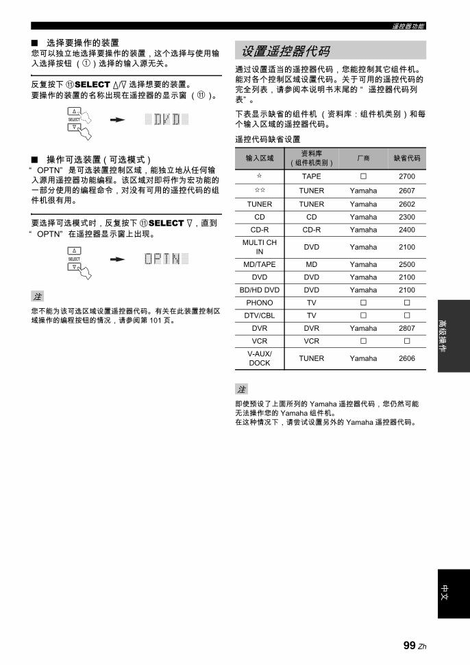
遥控器功能高
级操
作中
文
选择要操作的装置您可以独立地选择要操作的装置,这个选择与使用输入选择按钮 (1)选择的输入源无关。
反复按下 ASELECT k/n 选择想要的装置。要操作的装置的名称出现在遥控器的显示窗 (A)。
操作可选装置 ( 可选模式 )“ OPTN” 是可选装置控制区域,能独立地从任何输入源用遥控器功能编程。该区域对即将作为宏功能的一部分使用的编程命令,对没有可用的遥控代码的组件机很有用。
要选择可选模式时,反复按下 ASELECT n,直到“ OPTN” 在遥控器显示窗上出现。
您不能为该可选区域设置遥控器代码。有关在此装置控制区域操作的编程按钮的情况,请参阅第 101 页。
通过设置适当的遥控器代码,您能控制其它组件机。 能对各个控制区域设置代码。 关于可用的遥控代码的完全列表,请参阅本说明书末尾的 “ 遥控器代码列表” 。
下表显示缺省的组件机 (资料库:组件机类别)和每个输入区域的遥控器代码。
遥控代码缺省设置
即使预设了上面所列的 Yamaha 遥控器代码,您仍然可能无法操作您的 Yamaha 组件机。 在这种情况下,请尝试设置另外的 Yamaha 遥控器代码。
注
SELECT
SELECT
设置遥控器代码
输入区域 资料库(组件机类别) 厂商 缺省代码
TAPE 2700
TUNER Yamaha 2607
TUNER TUNER Yamaha 2602CD CD Yamaha 2300
CD-R CD-R Yamaha 2400MULTI CH
IN DVD Yamaha 2100
MD/TAPE MD Yamaha 2500DVD DVD Yamaha 2100
BD/HD DVD DVD Yamaha 2100PHONO TV
DTV/CBL TVDVR DVR Yamaha 2807VCR VCR
V-AUX/DOCK TUNER Yamaha 2606
注
99 Zh

遥控器功能
1 设置操作模式选择开关到 CSOURCE 然后按下输入选择按钮 (1), 或 ,选择您期望设置的输入区域。
2 使用圆珠笔或类似物体,按住LLEARN大约3秒钟。资料库名称 (例如,L;DVD) 和选择的输入区域名称 (例如,DVD) 在遥控器的显示窗 (A) 上交替出现。
y• 您可以设置装置的不同类型的遥控器代码到输入区
域。反复按下 3l / h 改变该库 (装置种类)。资料库选项: L;DVD, L;DVR, L;LD, L;CD, L;CDR,
L;MD, L;TAP ( 磁带 ), L;TUN ( 调谐器 ), L;AMP, L;TV, L;CAB( 有线 ), L;SAT ( 卫星 ), L;VCR
• 如果您希望设置另外的输入区域,请按下输入选择按钮 (1) 或 ,或反复按下 ASELECT k/n 选择输入区域。
• 一定要按住并保持LLEARN 3 秒以上,否则学习功能会被启动。
• 如果在 30 秒钟内,您没有完成下列各步骤,设定模式将被自动消除。 在此情况下,从步骤 2 重新开始。
3 按 3ENTER。显示窗上 (A) 显示为所选择组件机设定的 4 位数字代码。
如果没有设定代码,显示窗 (A) 上显示 “ 0000” 。
4 按下数字按钮(5),输入要使用组件机的4位数字遥控器代码。关于可用的遥控代码的完全列表,请参阅本说明书末尾的 “ 遥控器代码列表” 。
5 按下 3ENTER,设定该数字。如果设定成功,“ OK” 出现在遥控器的显示窗(A)。如果设定不成功,“ NG” 出现在遥控器的显示窗(A)。在此情况下,从步骤 3 重新开始。y如果您希望连续设置另外的装置的代码,请按下输入选择按钮 (1) 或 ,或反复按下 ASELECT k/n,选择装置,然后重复步骤 2 到 5。
6 再次按下 LLEARN 以退出设置模式。
7 按下6p(播放)或 AV POWER,确认使用遥控器是否能操作您的装置。
y如果操作不起作用而您的装置的厂商有一个以上的代码,请逐一尝试直到您找到了正确的那个。
• 如果您按下了相应步骤中未指示的按钮,或当您同时按下多个按钮时,“ ERROR” 出现在遥控器的显示窗 (A)。
• 随机提供的遥控器不包含针对市售的视频和音频组件机的所有可能的代码 (包括 Yamaha 组件机)。如果对于任何一个遥控器代码不能操作,请使用学习功能编程新的遥控器功能 (请参见第 101 页上的 “ 编程其他遥控器的代码” ),或使用装置附带的遥控器。
• 使用学习功能编程的功能优先于遥控器代码功能。
注
注
DTV/CBL VCRDVR V-AUX/DOCK
TUNER CD CD-R MULTI CH IN
DVD BD/HD DVD PHONOMD/TAPETV
SOURCE
AMP
LEARN
注
432
ENT+1009
5
1
76 8
CLASSICAL LIVE/CLUB ENTERTAIN MOVIE
SYSTEM MEMORY
SUR. DECODEENHANCERSTEREO
LEARN
AV
POWER
或
100 Zh

遥控器功能高
级操
作中
文
您可以从其他遥控器上编程遥控器控制。如果您希望编程遥控器代码所涵盖的基本功能所未包含的功能,或对应的遥控器代码无效时,使用该学习功能。在下图高亮区的那些按钮上,您可以编程其他遥控器的功能。 这些按钮能针对每个输入区域被单独编程。
此遥控器发射红外线。如果其它一个遥控器也使用红外线,此遥控器能学习它的大多数功能。但是,您可能无法对有些特殊信号或过长的传输进行编程。请参阅其他遥控器的使用说明书进行操作。
1 设置操作模式选择开关到 CSOURCE 然后按下输入选择按钮 (1)或 ,选择一个输入区域。
务必将输入模式选择开关设为 CSOURCE。当您将输入模式选择开关设置为 CAMP 和从其他遥控器编程一个遥控器代码时,被编程的键不能操作本机的放大器功能。
2 将此遥控器放在距离另外一个遥控器大约 5 到10 cm 的平整表面上,使得两个遥控器的红外线发射器互相对准。
3 使用圆珠笔或类似物体按 LLEARN。“ LEARN” 和选择的输入区域名称 (例如“ DVD” ) 在遥控器的显示窗 (A)上交替出现。
• 请勿按住 LLEARN 不放。如果您按住它 3 秒钟以上,遥控进入遥控器代码设置模式。
• 如果在 30 秒钟内,您没有完成下列各步骤,学习模式将被自动消除。在此情况下,从步骤 3 重新开始。
4 按下您想要编程新功能的按钮。“ LEARN” 出现在遥控器的显示窗 (A)。
编程其他遥控器的代码
注
注
–
+ +
––
+
MENUTITLE
TV MUTE TV INPUT MUTE
AVTV
ENTER
DISPLAY
AUDIO
MENUTITLE
432
ENT+1009
5
1
76 8
RETURN
VOLUMECHTV VOL
SRCH MODE
PURE DIRECTPRESET/CH
SET MENU
BAND
LEVEL
TV
SOURCE
AMP
SELECT
DTV/CBL VCRDVR V-AUX/DOCK
TUNER CD CD-R MULTI CH IN
POWER POWER POWERSTANDBY
SLEEPAUDIO SEL
DVD BD/HD DVD PHONOMD/TAPE
ONOFF CLEARLEARN RENAMEMACRO
REC
DISC SKIP
EFFECT
PARAMETER STRAIGHTA-E/CAT.
SRCH MODE
PURE DIRECTPRESET/CH
SET MENU
BAND
LEVEL
CLASSICAL LIVE/CLUB ENTERTAIN MOVIE
SYSTEM MEMORY
SUR. DECODE
FREQ/TEXT EON MODE – PTY SEEK – START
ENHANCERSTEREO
设置到SOURCE
注
AV
TV
SELECT
DT
V/C
BL
VC
RD
VR
V-AUX/DOCK
TU
NE
RC
DC
D-R
MULTI CH IN
PO
WE
RP
OW
ER
PO
WE
RSTANDBY
SL
EE
PA
UD
IO S
EL
DV
DB
D/H
D D
VD
PH
ON
OM
D/TA
PE
5 到 10 cm
其他遥控器
LEARN
101 Zh
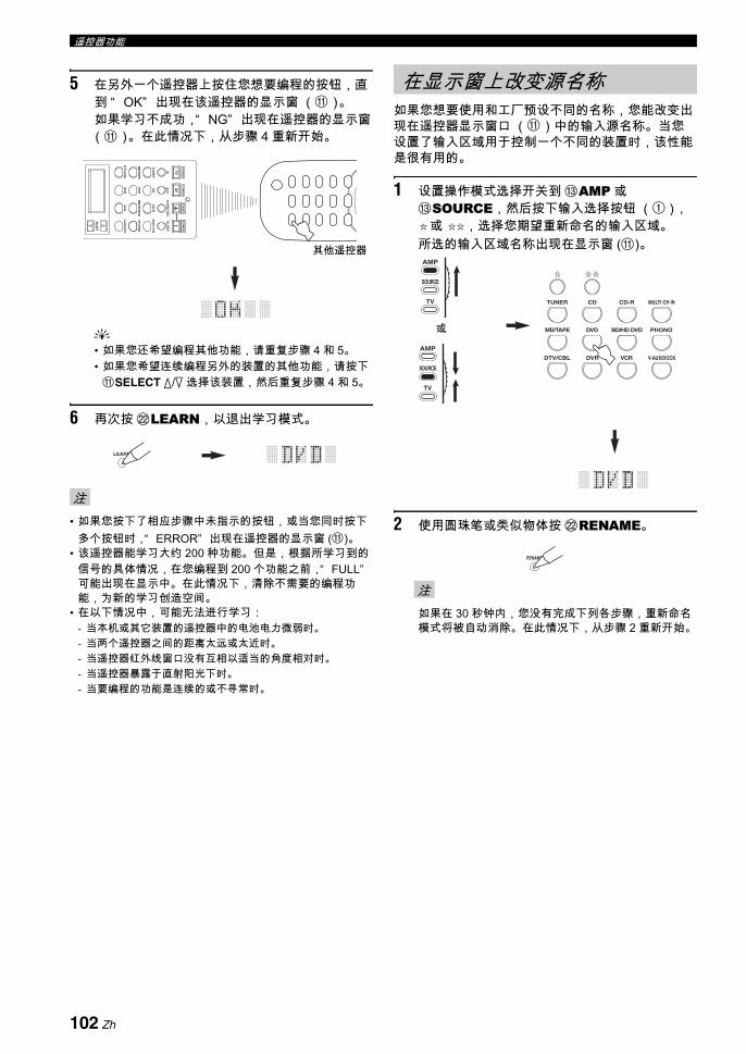
遥控器功能
5 在另外一个遥控器上按住您想要编程的按钮,直到 “ OK” 出现在该遥控器的显示窗 (A)。如果学习不成功,“ NG” 出现在遥控器的显示窗(A)。在此情况下,从步骤 4 重新开始。
y• 如果您还希望编程其他功能,请重复步骤 4 和 5。• 如果您希望连续编程另外的装置的其他功能,请按下ASELECT k/n 选择该装置,然后重复步骤 4 和 5。
6 再次按 LLEARN,以退出学习模式。
• 如果您按下了相应步骤中未指示的按钮,或当您同时按下多个按钮时,“ ERROR” 出现在遥控器的显示窗 (A)。
• 该遥控器能学习大约 200 种功能。但是,根据所学习到的信号的具体情况,在您编程到 200 个功能之前,“ FULL”可能出现在显示中。在此情况下,清除不需要的编程功能,为新的学习创造空间。
• 在以下情况中,可能无法进行学习:- 当本机或其它装置的遥控器中的电池电力微弱时。- 当两个遥控器之间的距离太远或太近时。- 当遥控器红外线窗口没有互相以适当的角度相对时。- 当遥控器暴露于直射阳光下时。- 当要编程的功能是连续的或不寻常时。
如果您想要使用和工厂预设不同的名称,您能改变出现在遥控器显示窗口 (A)中的输入源名称。当您设置了输入区域用于控制一个不同的装置时,该性能是很有用的。
1 设置操作模式选择开关到 CAMP 或CSOURCE,然后按下输入选择按钮 (1),
或 ,选择您期望重新命名的输入区域。所选的输入区域名称出现在显示窗 (A)。
2 使用圆珠笔或类似物体按 LRENAME。
如果在 30 秒钟内,您没有完成下列各步骤,重新命名模式将被自动消除。在此情况下,从步骤 2 重新开始。
注
AV
TV
SELECT
DT
V/C
BL
VC
RD
VR
V-AUX/DOCK
TU
NE
RC
DC
D-R
MULTI CH IN
PO
WE
RP
OW
ER
PO
WE
RSTANDBY
SL
EE
PA
UD
IO S
EL
DV
DB
D/H
D D
VD
PH
ON
OM
D/TA
PE
其他遥控器
LEARN
在显示窗上改变源名称
注
DTV/CBL VCRDVR V-AUX/DOCK
TUNER CD CD-R MULTI CH IN
DVD BD/HD DVD PHONOMD/TAPE
TV
SOURCE
AMP
TV
SOURCE
AMP
或
RENAME
102 Zh
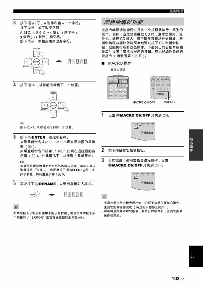
遥控器功能高
级操
作中
文
3 按下 3k / n,以选择和输入一个字符。按下 3n,如下改变字符: A 到 Z, 1 到 9, 0, + ( 加 ), - ( 连字号 ), ;( 分号 ), / ( 斜线 ), 和空格。 按下 3k,以相反顺序改变字符。
4 按下 3h,以移动光标到下一个位置。
y按下 3l,以移动光标到前一个位置。
5 按下 3ENTER,设定新名称。如果重新命名成功,“ OK” 出现在遥控器的显示窗 (A)。如果重新命名不成功,“ NG” 出现在遥控器的显示窗 (A)。 在此情况下,从步骤 3 重新开始。y如果您希望继续重新命名另外的输入区域,请按下输入选择按钮 (1) 或 ,或反复按下 ASELECT k/n,选择该装置,然后重复步骤 3 到 5。
6 再次按下 LRENAME,以退出重新命名模式。
如果您按下了相应步骤中未指示的按钮,或当您同时按下多个按钮时,“ ERROR” 出现在遥控器的显示窗 (A)。
宏指令编程功能能通过只按一个按钮就执行一系列的操作。例如,当您想要播放 CD 时,通常您要打开组件机,选择 CD 输入,按下播放按钮以开始播放。宏指令编程功能让您能简单地通过按下 CD 宏指令按钮,就能执行所有这些操作。下面列出的宏指令按钮是工厂设置了宏指令程序的按钮。您也能编程自己的宏指令 (请参阅第 105 页)。
MACRO 操作
1 设置 LMACRO ON/OFF 开关到 ON。
2 按下期望的宏指令按钮。
3 当您完成了使用宏指令编程操作,设置LMACRO ON/OFF 开关到 OFF。
• 当遥控器执行宏指令程序时,它将不接受任何其它操作,直到宏指令操作完成 (传送指示器停止闪烁)。
• 继续将遥控器对准宏指令正在进行的组件机,直到宏指令操作已完成。
注
ENTER
A/B/C/D/E
PRESET/CH
ENTER
A/B/C/D/E
PRESET/CH
RENAME
宏指令编程功能
注
AVTV
ENT+1009
DTV/CBL VCRDVR V-AUX/DOCK
TUNER CD CD-R MULTI CH IN
POWER POWER POWERSTANDBY
SLEEPAUDIO SEL
DVD BD/HD DVD PHONOMD/TAPE
ONOFF CLEARLEARN RENAMEMACRO
REC
DISC SKIP
FREQ/TEXT EON MODE – PTY SEEK – START
MACROMACRO ON/OFF
宏指令按钮
ONOFF CLEARLEARNMACRO
ONOFF CLEARLEARNMACRO
103 Zh

遥控器功能
缺省宏指令功能
*1 通过将组件机连接到本机后部面板上的 AC OUTLET(S),您能打开某些连接到本机的组件机 (包含 Yamaha 组件机)。根据装置的情况,电源控制可能不与本机同步。有关详情,请参阅连接的装置的使用说明书。
*2 如果为电视机设置遥控器代码为 DTV/CBL 或 PHONO (请参阅第 99 页),您只要打开电视机电源即可,而不必选择输入源。为 DTV 设置的遥控器代码优先于 PHONO。
*3 当 TUNER 被选作输入源时,在本机设为待机模式之前将播放 后一个接收到的电台。*4 任何兼容 Yamaha 遥控器的 MD 录制机,CD 播放机,CD 录制机,DVD 播放机,Blu-ray Disc 播放机 , HD DVD 播放机
或 DVD 刻录机都能开始播放。当使用宏指令以操作其它装置时,您需要事先编程那个装置输入区域上的播放按钮 (请参阅第 101 页)或设置一个遥控器代码 (请参阅第 99 页)。
按下宏指令按钮 要自动按顺序传输这些信号首先 其次 其三
(*1)
(CD 区域)(*4)
(CD-R 区域)(*4)
(MD/TAPE 区域)
(DVD 区域)(*4)
(BD/HD DVD 区域)
(DVR 区域)(*4)
(VCR 区域)(*4)
STANDBY STANDBY
POWER POWER
( )
TV
POWER
( )
POWER
POWER
TUNER
POWER
TUNER
( )
CD CD
CD-R CD-R
MULTI CH IN MULTI CH IN
MD/TAPE MD/TAPE
DVD DVD
BD/HD DVD BD/HD DVD
PHONO PHONO
DTV/CBL DTV/CBL
DVR DVR
VCR VCR
V-AUX/DOCK V-AUX/DOCK
104 Zh
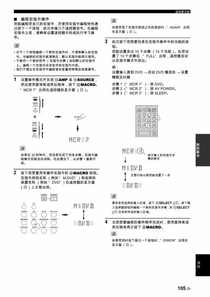
遥控器功能高
级操
作中
文
编程宏指令操作您能编程您自己的宏指令,并使用宏指令编程特性通过按下一个按钮,依次传输几个遥控器命令。在编程宏指令之前,请确保设置遥控器代码或执行学习操作。
• 对于一个按钮编程一个新的宏指令时,不清除默认的宏指令。当编程的宏指令被清除后,默认宏指令能再次使用。
• 不能将一个新的信号 (宏指令步骤)加到默认的宏指令上。 编程一个宏指令会改变所有宏指令内容。
• 我们不建议在宏指令中编程诸如音量控制等的连续操作。
1 设置操作模式开关到 CAMP 或 CSOURCE,然后使用圆珠笔或类似物体,按下 LMACRO。“ MCR ?” 出现在遥控器的显示窗 (A)。
如果在 30 秒钟内,您没有完成下列各步骤,宏指令编程模式将被自动消除。在此情况下,从步骤 1 重新开始。
2 按下您想要用来操作宏指令的 LMACRO 按钮。宏指令按钮名称 (例如 “ M;DVD” )和选择的装置名称 (例如 “ DVD” ) 在遥控器的显示窗(A)上交替出现。
如果您按了宏指令按钮之外的按钮时,“ AGAIN” 出现在显示窗 (A)。
3 依次按下您想要包含在宏指令操作中的功能的按钮。您能设置多达 10 个步骤 (10 个功能)。在您设置了 10 个步骤后,“ FULL” 出现,遥控器自动从宏指令模式中退出。
例:设置输入源到 DVD → 启动 DVD 播放机 → 设置睡眠定时器
步骤 1 (“ MCR 1” ):按 DVD。步骤 2 (“ MCR 2” ):按 AV POWER。步骤 3 (“ MCR 3” ):按 SLEEP。
要改变所选择的输入区域,按下 ASELECT k/n。按下输入选择器按钮将编程一个新的宏指令步骤,而 ASELECT k/n 仅改变所选的输入区域。
4 当您想要编程的操作顺序完成时,使用圆珠笔或类似物体再次按下 LMACRO。
如果您同时按下超过一个按钮时,“ ERROR” 出现在显示窗 (A)。
注
注
MACRO
TV
SOURCE
AMP
TV
SOURCE
AMP
或
DTV/CBL VCRDVR V-AUX/DOCK
TUNER CD CD-R MULTI CH IN
DVD BD/HD DVD PHONOMD/TAPE
POWERSTANDBY
注
注
注
AVTV
SELECT
DTV/CBL VCRDVR V-AUX/DOCK
TUNER CD CD-R MULTI CH IN
POWER POWER POWERSTANDBY
SLEEPAUDIO SEL
DVD BD/HD DVD PHONOMD/TAPE
1
2
3
指示输入的宏指令步骤的数目
交替闪烁以使您能设置下一步
105 Zh

遥控器功能
您能清除每个功能设置中所有的变化,例如学习到的功能,宏指令功能,重新命名的输入区域名称和设置遥控器代码。
清除功能设置
1 使用圆珠笔或类似物体,设置操作模式开关到CAMP 或 CSOURCE,然后按下 LCLEAR。“ CLEAR” 出现在显示窗 (A)。
如果在 30 秒钟内,您没有完成下列各步骤,清除模式将被自动消除。在此情况下,从步骤 1 重新开始。
2 按下 3k / n 以选择清除模式。
L;CD( 等 ) ( 左;输入区域的名称)清除相应输入区域的所有学习到的功能。 组件机名称在分号 (;) 后显示。按一个输入选择器按钮以选择输入区域。
L;AMP 清除本机的控制放大器功能的所有学习到的功能。
L;ALL 清除所有学习到的功能。
M;ALL 清除所有编程的宏指令。
RNAME 清除所有重新命名的信号源名称。
FCTRY 清除所有遥控器功能并将遥控器恢复到工厂设置。
3 再次按住 LCLEAR 大约 3 秒钟。“ WAIT” 出现在显示窗 (A)。如果清除成功,“ C;OK” 出现在遥控器的显示窗 (A)
y一旦您清除了一个按钮的一个学习功能,该按钮恢复到工厂设定 (或厂商设定,如果您已经设定了遥控器代码)。
• “ L;ALL” 和 “ FCTRY” 可能需要大约 30 秒钟才能完成。
• 如果清除不成功,“ C;NG” 出现在显示窗 (A)。在此情况下,从步骤 2 重新开始。
• 如果您按下了各自步骤中未指示的按钮,或在您同时按下了多个按钮时,“ ERROR” 出现在显示窗 (A)。
4 再次按 LCLEAR 退出。
清除一个学习到的功能您能清除各个控制区域内一个特定的按钮学习到的功能。
1 设置操作模式选择开关到 CAMP 或CSOURCE,然后按下输入选择按钮 (1), 或
,选择包含您期望清除功能的输入区域。所选的装置的名称出现在显示窗中。
清除配置
注
CLEAR
TV
SOURCE
AMP
TV
SOURCE
AMP
或
注
CLEAR
DTV/CBL VCRDVR V-AUX/DOCK
TUNER CD CD-R MULTI CH IN
DVD BD/HD DVD PHONOMD/TAPE
TV
SOURCE
AMP
TV
SOURCE
AMP
或
106 Zh

遥控器功能高
级操
作中
文
2 使用圆珠笔或类似物体按 LLEARN。“ LEARN” 和选择的装置名称 (例如 “ DVD” )在遥控器的显示窗上交替出现。
• 请勿按住LLEARN不放。 如果您按住它 3 秒钟以上,遥控器进入遥控器代码设置模式。
• 如果在 30 秒钟内,您没有完成下列各步骤,学习模式将被自动消除。在此情况下,从步骤 2 重新开始。
3 使用圆珠笔或类似物体按住 LCLEAR,然后按您想要清除的按钮 3 秒钟以上。如果清除成功,“ C;OK” 出现在显示窗 (A)。 一旦 “ C;OK” 出现在遥控器的显示窗,释放用来按下 LCLEAR 的圆珠笔或类似物体,退出清除模式。遥控器返回到学习模式。
y• 如果您希望连续清除另外的功能,请重复步骤 4。• 如果您希望连续清除另外的装置的其他功能,请按下ASELECT k/n,选择输入区域,然后重复步骤 3。
• 一旦您清除了一个学习到的功能时,此按钮恢复到工厂设置 (或如果您设置了遥控器代码,则恢复到厂商设置)。
4 再次按 LLEARN 退出。
• 如果清除不成功,“ C;NG” 出现在遥控器的显示窗(A)。在此情况下,从步骤 2 重新开始。
• 如果您同时按下超过一个按钮时,“ ERROR” 出现在显示窗 (A)。
清除一个宏指令功能您可以清除特定的宏指令按钮的已经编程的功能。
1 设置操作模式开关到 CAMP 或 CSOURCE,然后使用圆珠笔或类似物体,按下 LMACRO。“ MCR ?” 出现在遥控器的显示窗 (A)。
如果在 30 秒钟内,您没有完成下列各步骤,宏指令编程模式将被自动消除。在此情况下,从步骤 1 重新开始。
2 使用圆珠笔或类似物体按住 LCLEAR,然后按您想要清除的宏指令按钮大约 3 秒钟。如果清除成功,“ C;OK” 出现在遥控器的显示窗(A)。
y• 如果您希望连续清除另外的功能,请重复步骤 2。• 一旦您清除了一个已经编程的功能时,此按钮恢复到
工厂设置 (或如果您设置了遥控器代码,则恢复到厂商设置)。
3 再次按 LMACRO,以退出宏指令编程模式。
• 如果清除不成功,“ C;NG” 出现在遥控器的显示窗(A)。在此情况下,从步骤 2 重新开始。
• 如果您同时按下多个按钮时,“ ERROR” 出现在遥控器的显示窗 (A)。
注
注
LEARN
CLEARLEARN RENAME
MODE – PTY SEEK – START
注
注
MACRO
TV
SOURCE
AMP
TV
SOURCE
AMP
或
ONOFF CLEARLEARN RENAMEMACRO
DTV/CBL VCRDVR V-AUX/DOCK
DVD BD/HD DVD PHONOMD/TAPE
107 Zh
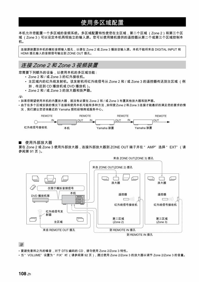
本机允许您配置一个多区域的音频系统。多区域配置特性使您在主区域,第二个区域 (Zone 2)和第三个区域 (Zone 3)可以设定本机再现独立的输入源。您可以使用随机提供的遥控器从第二个或第三个区域控制本机。
您需要下列额外的设备,以使用本机的多区域功能 :• Zone 2 和 / 或 Zone 3 的红外接收机。• 主区域内的红外线发射机。该发射机将红外线信号从 Zone 2 和 / 或 Zone 3 的遥控器传送到主区域 (例
如,传送到 CD 播放机或 DVD 播放机)。• Zone 2 和 / 或 Zone 3 的放大器和扬声器。
y• 如果您期望使用本机的内置放大器,就没有必要在 Zone 2 和 / 或 Zone 3 布置其他放大器和扬声器。• 由于在多个区域安装的情况下连接和使用本机可能有多种方法,如何使 Zone 2 和 Zone 3 连接才能 好的满足您的要求的情
况,我们建议您咨询 近的 Yamaha 授权经销商或服务中心。
使用外部放大器要在 Zone 2 或 Zone 3 使用外部放大器,连接外部放大器到 ZONE OUT 端子并在 “ AMP” 选择 “ EXT” (请参阅第 91 页)。
• 要避免意料之外的噪音,对于 DTS 编码的 CD,请勿使用 Zone 2/Zone 3 特性。• 当 “ VOLUME” 设置为 “ FIX” 时 (请参阅第 92 页),通过使用 Zone 2/Zone 3 的放大器以调节 Zone 2/Zone 3 的音量。
使用多区域配置
连接源装置到本机的模拟音频输入插孔,以便在 Zone 2 或 Zone 3 播放该输入源。本机不能将来自 DIGITAL INPUT 和HDMI 插孔输入的音频信号输出到 ZONE OUT 插孔。
连接 Zone 2 和 Zone 3 视频装置
注
OUTOUT IN
REMOTE
IN
REMOTE
OUT IN
REMOTE REMOTE
本机 Yamaha 装置 Yamaha 装置红外线信号接收机
MAIN
ZONE 2
ZONE 3
红外线信号发射器
DVD 播放机等
放大器
遥控器
红外线信号接收机
放大器
遥控器
红外线信号接收机
第二区域(Zone 2)
第三区域(Zone 3)主区域
本机
来自 ZONE OUT(ZONE 2) 插孔
来自 ZONE OUT(ZONE 3) 插孔
到 REMOTE IN 插孔到 REMOTE IN 插孔来自 REMOTE OUT 插孔
仅限于模拟音频信号
108 Zh

使用多区域配置高
级操
作中
文
使用本机的内部放大器
如果您想使用本机的内部放大器之一 (SP1 或 SP2)直接连接 Zone 2 或 Zone 3 扬声器到 SP1 或 SP2 扬声器端子,然后选择 “ [SP1]” 或 “ [SP2]” 用于“ AMP” ( 请参阅第 91 页 )。
如果您想使用本机的两个内部放大器 (SP1 和 SP2)直接连接 Zone 2 或 Zone 3 扬声器到 SP1 和 SP2 扬声器端子,然后选择 “ BOTH” 用于 “ AMP” ( 请参阅第91 页 )。
您可以使用前面板的控制按钮或遥控器选择期望控制的区域。
选择 Zone 2 或 Zone 3前面板操作
1 按下前面板的 PZONE 2 ON/OFF 或 PZONE 3 ON/OFF,分别打开或关闭 Zone 2或 Zone 3。
2 反复按下前面板上的PZONE CONTROLS 按钮,选择您期望控制的区域。每按下PZONE CONTROLS 一次 , 前面板显示器按以下改变,当前选择的区域对应的指示器闪烁 10 秒钟。但是,当主区域被选择时,没有指示器闪烁。
ZONE2操作 Zone 2 放大器或调谐器功能。
ZONE3操作 Zone 3 放大器或调谐器功能。
重要安全注意事项本接收机的 SP1 或 SP2 扬声器端子不应该连接到被动扬声器选择盒或在每个声道使用多个扬声器。连接到被动扬声器选择盒或每个声道多于一个扬声器可能引起超低阻抗负荷从而导致放大器损坏。有关正确用法请参阅本用户说明书。对于所有声道,必须在任何时候都保持 小扬声器阻抗数值。该数值刻写在您的接收机的后面板上。
R L
+
–
SP2
SINGLE
R L+–+ –
BI-AMPSURROUND BACK/
PRESENCE/ZONE 2/ZONE 3ZONE 2/ZONE 3
R L
SP1
+–+ –
第三区域(Zone 3)
本机
第二区域(Zone 2)
控制 Zone 2 或 Zone 3
ZONE2 ZONE3
当主区域被选择时,没有指示器闪烁。
109 Zh

使用多区域配置
y• 当作选择的区域在前面板显示器上闪烁时,您必须在
10 秒钟内完成此步骤。 否则,当前选择的区域模式被自动解除。 在此情况下,请再次按下PZONE CONTROLS。
• 当 Zone 2 和 Zone 3 两者都打开时,初始设置为ZONE2。
3 请参阅“ 选择 Zone 2 或 Zone 3 的输入源” , “ 调节 Zone 2 或 Zone 3 的音量水平” , “ 在 Zone 2或 Zone 3 调节扬声器水平的平衡” 或 第 111 页上的 “ 调节 Zone 2 或 Zone 3 的音质” 以便进一步操作。
遥控器操作
1 设置操作模式选择开关到 CAMP,然后反复按下 ASELECT k,选择您期望控制的区域。“ ZONE 2” 或 “ ZONE 3” 在遥控器的显示窗(A)显示。
2 请参阅“ 选择 Zone 2 或 Zone 3 的输入源” , “ 调节 Zone 2 或 Zone 3 的音量水平” , “ 在 Zone 2或 Zone 3 调节扬声器水平的平衡” 或 第 111 页上的 “ 调节 Zone 2 或 Zone 3 的音质” 以便进一步操作。
3 按下 ASELECT k/n,退出 Zone 2/Zone 3 模式。
使用遥控器开启或关闭 Zone 2 和 / 或 Zone 3根据出现在显示窗口 (A)上所选的区域的情况,遥控器上的 8POWER 和 7STANDBY 具有不同的作用。
• 当选择主区域,Zone 2 或 Zone 3 模式时,您能打开主区域,Zone 2 或 Zone 3 或使其分别进入待机模式。
• 当选择所有模式时,按下 8POWER 同时打开主区域,Zone 2 和 Zone 3,然后按下7STANDBY 使得它们同时进入待机模式。
• 当遥控器处于主区域模式时,当按下 8POWER 或7STANDBY 时,“ MAIN” 出现几秒钟。
• 仅当按下 ASELECT n 时,“ ALL” 出现在遥控器的显示窗 (A)。
SELECT
TV
SOURCE
AMP
或
控制模式 显示窗口 (A) POWER 和 STANDBY
主区域模式 选择的输入区域名称
仅打开主区域或将其设置为待机模式。
Zone 2 模式“ ZONE 2” 或“ 2 ;所选择的输入区域的名称”
打开 Zone 2 或将其设置为待机模式。
Zone 3 模式“ ZONE 3” 或 “ 3;所选择的输入区域的名称”
打开 Zone 3 或将其设置为待机模式。
所有模式 “ ALL”
8POWER: 打开主区域,Zone 2和 Zone 3。7STANDBY: 设置主区域,Zone 2 和 Zone 3 进入待机模式。
注
110 Zh

使用多区域配置高
级操
作中
文
选择 Zone 2 或 Zone 3 的输入源
旋转前面板上的CINPUT 选择开关 (或设置操作模式选择开关到 CAMP 然后按下遥控器上的输入选择器按钮之一),选择被选择区域的输入源。如果使用遥控器来选择输入源 , 当 Zone 2 或 Zone 3被分别选择时,“ 2 ;选择的输入源名称” 或 “ 3:选择的输入源名称” 被显示在遥控器的显示窗(A)。
• 选择 “ TUNER” 作为输入源,以便在所选择的区域使用 FM/AM 功能。 关于 FM/AM 调谐说明的详情,第 54 页上的 “ FM/AM 调谐” 。
• 选择 “ V-AUX” 作为输入源,在选择的区域,播放驳接在 Yamaha iPod 多用平台(比如 YDS-10,另售)上的 iPod 的输入源。 您只能使用简单遥控模式控制 iPod (请参阅第 61 页)。
输入源在所有区域之间共享。您不能在多个区域同时选择相同的输入源。
y当作选择的区域在前面板显示器上闪烁时,您必须在 10 秒钟内完成此步骤。否则,当前选择的区域模式自动取消。 在此情形下,请再次按下前面板的PZONE CONTROLS。
调节 Zone 2 或 Zone 3 的音量水平
旋转前面板的QVOLUME (或按下遥控器的BVOLUME +/-),调节所选择区域的音量水平。
y按下遥控器上的 DMUTE 以默音来自选择的区域的声音输出。
仅当 “ VOLUME” 在 “ ZONE SET” 被设置到 “ VAR” 时(请参阅第 92 页),当您在 Zone 2 或 Zone 3 使用外部放大器时, BVOLUME +/- 可以使用。
在 Zone 2 或 Zone 3 调节扬声器水平的平衡
反复按下ETONE CONTROL,选择“ BALANCE” ,然后旋转前面板上的NPROGRAM,调节选择的区域的前左和右扬声器水平的平衡。
调节 Zone 2 或 Zone 3 的音质
设置操作模式选择开关到 CAMP,然后按下遥控器的 CH +/-,分别调节高频反应 (TREBLE) 或 TV VOL +/- 调节低频反应 (BASS)。
y您也可以使用前面板的ETONE CONTROL 调节 Zone 2 或Zone 3 的音调质量。有关详情,请参阅第 52 页上的 “ 调节音调质量” 。
在调节相应区域的音调质量之前,请检查遥控器的显示窗(A) 上显示有 “ ZONE 2” 或 “ ZONE 3” (请参阅第 110页)。
启动 Zone 2 或 Zone 3 操作模式之后,进行以下操作。
注
注
注
–
+TV VOL
+
–CH
TV
SOURCE
AMP
TREBLE
BASS
111 Zh

使用多区域配置
使用 Zone 2/Zone 3 遥控器( 欧洲型号除外 )
您可以使用附带的 Zone 2/Zone 3 遥控器,操作 Zone 2 或 Zone 3 功能。首先,妥当设置 ID1/ID2 开关和ZONE 2/ZONE 3 开关。
操作放大器功能
1 输入选择器按钮为控制区域选择期望的输入源。
4 ID1/ID2 开关在 ID1 和 ID2 之间切换遥控器 ID( 请参阅第 114 页 )。
5 POWER打开 Zone 2 或 Zone 3。
只有当向内按下前面板上的AMASTER ON/OFF 按钮到ON 位置时,该按钮才能操作。
6 STANDBY设置 Zone 2 或 Zone 3 到待机模式。
只有当向内按下前面板上的AMASTER ON/OFF 按钮到ON 位置时,该按钮才能操作。
7 VOLUME +/-增加或减少 Zone 2 或 Zone 3 的音量水平。
8 MUTE默音 Zone 2 或 Zone 3 的声音。再次按此以恢复音频输出到以前的音量水平。
9 ZONE 2/ZONE 3 开关在 Zone 2 的操作模式和 Zone 3 的操作模式之间切换。
操作调谐器功能 ( 请参阅第 54 页 )
2 PRESET k / n当前面板显示器上冒号 (:)显示时,选择 8 个预设电台号码 (1 到 8) 之一 (请参阅第 56 页)。
3 A/B/C/D/E选择预先设定的电台组 (A 到 E) 之一 ( 请参阅第 55页 )。
注
TUNER CD CD-R
MD/TAPE DVD BD/HD DVD PHONO
DTV/CBL VCR V-AUX/DOCKDVR
POWER
STANDBY
A/B/C/D/E
PRESET VOLUME
ZONE 3ZONE 2ID2ID1
MUTE
4 9
8
7
6
5
1
2
3
注
选择 “ TUNER” 作为控制区域的输入源 , 以便使用以下功能。
112 Zh

中文
高级
操作
本机具有附加的菜单,可以在前面板显示器上显示。高级设置菜单提供附加的操作以便对本机的操作进行调节和用户定制。改变初始设置 (在每个参数下以粗体指示)以反映您的收听环境的需要。
• 您进行的设置在下一次您向内按下AMASTER ON/OFF 到 ON 位置打开本机时生效 (请参阅第 33 页)。• 当您在使用高级设置菜单时,只有AMASTER ON/OFF, OSTRAIGHT 和NPROGRAM 选择开关有效。• 当您在使用高级设置菜单时,所有其他操作都不可能。• 高级设置菜单仅在前面板显示器上可用。
1 按下前面板上的AMASTER ON/OFF 按钮,向外释放到 OFF 位置,关闭本机。
2 按下并保持OSTRAIGHT,然后向内按下AMASTER ON/OFF 到 ON 位置,打开本机。本机打开,“ ADVANCED MENU” 出现在前面板显示器上。
3 旋转NPROGRAM 选择器,选择您想要调节的参数。所选择的参数名称在前面板显示器上出现。
4 反复按下OSTRAIGHT,改变所选择参数的设置。
5 按下AMASTER ON/OFF,向外释放到 OFF 位置,以保存新设置并关闭本机。
y您进行的设置在下次打开本机时生效。
扬声器阻抗 SPEAKER IMP.使用该功能设定本机的阻抗以使其与扬声器相匹配。选择: 8Ω MIN, 6Ω MIN
• 选择 “ 8Ω MIN” ,以设定扬声器阻抗为 8 Ω。• 选择 “ 6Ω MIN” ,以设定扬声器阻抗为 6 Ω。
遥控传感器 REMOTE SENSOR使用该性能激活或解除本机前面板上的遥控传感器的信号接收性能。选择:ON, OFF
• 如果您想要激活遥控传感器的信号接收性能,请选择 “ ON” 。
• 如果您想要解除遥控传感器的信号接收性能,请选择 “ OFF” 。
大多数情况,我们推荐设置该参数到 “ ON” 。
高级设置
注
使用高级设置菜单
EFFECT
STRAIGHT
MASTER
在按住的同时
SPEAKER IMP. 扬声器 阻抗水平
8Ω MIN
前扬声器 每个扬声器的阻抗必须为 8 Ω 或更高。
中央扬声器
每个扬声器的阻抗必须为 8 Ω 或更高。环绕声扬声器
后环绕声扬声器
6Ω MIN
前扬声器 每个扬声器的阻抗必须为 4 Ω 或更高。
中央扬声器
每个扬声器的阻抗必须为 6 Ω 或更高。环绕声扬声器
后环绕声扬声器
注
113 Zh
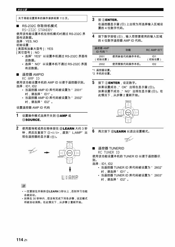
高级设置
RS-232C 存取待机模式 RS-232C STANDBY
使用该性能设置本机在待机模式时通过 RS-232C 界面传送数据。选择:YES, NO初始设置:[ 美国和加拿大型号 ]:YES[ 其它型号 ]:NO
• 选择“ YES” 以设置本机通过 RS-232C 界面传送数据。
• 选择 “ NO” 以设置本机不通过 RS-232C 界面传送数据。
遥控器 AMPID RC AMP ID
使用该功能设置本机的 AMP ID 以便于遥控器识别。选择:ID1, ID2
• 当遥控器 AMP ID 库代码被设置为 “ 2001”时,请选择 “ ID1” 。
• 当遥控器 AMP ID 库代码被设置为 “ 2002”时,请选择 “ ID2” 。
设置遥控器 AMP ID 代码
1 设置操作模式选择开关到 CAMP 或CSOURCE。
2 使用圆珠笔或类似物体按住 LLEARN 大约 3 秒钟,然后反复按下 3l / h,直到 “ L;AMP” 出现在遥控器的显示窗 (A)。
• 一定要按住并保持LLEARN 3 秒以上,否则学习功能会被启动。
• 如果在 30 秒钟内,您没有完成下列各步骤,设定模式将被自动消除。在此情况下,从步骤 2 重新开始。
3 按 3ENTER。在遥控器显示窗 (A) 上出现为所选择输入区域设置的 4 位数字代码。
4 按下数字按钮 (5),输入您想要使用的输入区域的 4 位数字遥控器 AMP ID 代码。
*1 遥控器设置。*2 本机的设置。
5 按下 3ENTER,设定数字。如果设置成功,“ OK” 出现在显示窗 (A)。如果设置不成功,“ NG” 出现在显示窗 (A)。在此情况下,从步骤 2 重新开始。
6 再次按下 LLEARN 以退出设置模式。
遥控器 TUNERID RC TUNER ID
使用该功能设置本机的 TUNER ID 以便于遥控器识别。选择:ID1, ID2
• 当遥控器 TUNER ID 库代码被设置为 “ 2602”时,请选择 “ ID1” 。
• 当遥控器 TUNER ID 库代码被设置为 “ 2603”时,请选择 “ ID2” 。
关于高级设置菜单的操作请参阅第 113 页。
注
LEARN
ENTER
A/B/C/D/E
PRESET/CH
遥控器 AMP ID 代码 *1 功能 RC AMP ID*2
2001(初始设置)
使用缺省代码操作本机。 ID1 (初始设置)
2002 使用替换代码操作本机。 ID2
ENTER
A/B/C/D/E
PRESET/CH
LEARN
114 Zh

高级设置高
级操
作中
文
设置遥控器 TUNERID
1 设置操作模式选择开关到 CAMP 或CSOURCE,然后按下遥控器的 1TUNER,选择调谐器改变遥控器 ID。
2 使用圆珠笔或类似物体按住 LLEARN 大约 3 秒钟,直到 “ L;TUN” 和 “ TUNER” 交替出现在遥控器的显示窗 (A)。
• 一定要按住并保持LLEARN 3 秒以上,否则学习功能会被启动。
• 如果在 30 秒钟内,您没有完成下列各步骤,设定模式将被自动消除。在此情况下,从步骤 2 重新开始。
3 按 3ENTER。在遥控器显示窗 (A) 上出现为所选择输入区域设置的 4 位数字代码。
4 按下数字按钮 (5),输入您想要使用的输入区域的 4 位数字遥控器代码。
*1 遥控器设置。*2 本机的设置。
5 按下 3ENTER,设定数字。如果设置成功,“ OK” 出现在显示窗 (A)。如果设置不成功,“ NG” 出现在显示窗 (A)。在此情况下,从步骤 2 重新开始。
6 再次按下 LLEARN 以退出设置模式。
注
LEARN
3 秒钟
遥控器TUNERID
代码 *1 功能 RC TUNER
ID*2
2602 (初始设置)
使用缺省代码操作本机。 ID1 (初始设置)
2603 使用替换代码操作本机。 ID2
LEARN
115 Zh

高级设置
调谐器频率步长 TUNER FRQ STEP(仅限亚洲和通用型号)
使用该功能,根据你所在地区的频率空间,设置调谐器频率步长。选择:AM10/FM100, AM9/FM50
• 对于北美洲 , 中美洲和南美洲,选择“ AM10/FM100” 。
• 对于其他所有地区,选择 “ AM9/FM50” 。
双重放大器设置 BI-AMP使用该性能启动或解除双重放大器功能 (请参阅第19 页)。选择:ON, OFF
• 如果您想要启动双重放大器功能,选择“ ON” 。
• 如果您想要关闭双重放大器功能,选择“ OFF” 。
当 “ BI-AMP” 设置到 “ ON” 时,SURROUND BACK 端子不能用于连接后环绕声扬声器,因为 SURROUND BACK端子已经被用于双重放大器连接 ( 请参阅第 19 页 )。
参数初始化 INITIALIZE使用该功能复位本机的参数到工厂初始设置。您可以选择要初始化的类别。选择: DSP PARAM, VIDEO, ALL, CANCEL
• 选择“ DSP PARAM” , 初始化所有声场程序参数的设置 ( 请参阅第 64 页 )。
• 选择 “ VIDEO” ,初始化 “ VIDEO SET” ( 请参阅第 89 页 ) 的参数和 “ OSD SHIFT” ( 请参阅第 88 页 ) 和 “ DISPLAY SET” 的“ GRAY BACK” ( 请参阅第 88 页 )。
• 选择 “ ALL” ,对本机的所有参数初始化。• 选择 “ CANCEL” ,取消初始化操作。
• 高级设置菜单参数不被初始化。• 在声场程序菜单中使用 “ INITIALIZE” 可以初始化期望的
程序的参数 (请参阅第 64 页)。
HDMI 视频监视器检查 MONITOR CHECK
使用此功能激活或解除本机的监视器检查功能。当“ MONITOR CHECK” 设置为 “ YES” 时,本机接收通过 HDMI 连接到视频监视器的视频信号分辨率的信息,您只能选择 “ HDMI SCALING” 的视频监视器支持的分辨率 (请参阅第 89 页)。当“ MONITOR CHECK” 设置为 “ SKIP” 时,您仅可以选择 “ HDMI SCALING” 支持的任何分辨率。选择:YES, SKIP
关于高级设置菜单的操作请参阅第 113 页。
注
注
116 Zh

故障排除补
充信
息中
文
当本机工作不正常时,请参阅下面的表。 如果您遇到的问题没有列在下面,或如果下面给出的指导不起作用,请将本关闭,断开电源导线,并联络距离您 近的 Yamaha 经销商或服务中心。
一般
故障排除
问题 原因 措施 参考页码
电源打开后本机不能启动且立即进入待机模式。
电源导线没有连接或插头没有完全插入。 请稳固连接电源导线。
扬声器阻抗设置不正确。 设置匹配您的扬声器的扬声器阻抗。 33
保护电路被启用。 请确保在本机上的以及所有扬声器上的所有扬声器线路连接是稳固的,且每根连接的电线不接触到其相关连接之外的任何物体。
16
本机曾被暴露在强烈的外部电击 (例如闪电或强烈的静电)。
关闭本机,断开电源线,过 30 秒钟后再次插回,然后正常使用。
无声音。 输入或输出电缆连接不正确。 请正确连接导线。 如果问题仍然存在,导线可能有故障。
24-31
音频输入插孔选择设置在 “ HDMI” ,“ COAX/OPT” 或 “ ANALOG” 。
设置音频输入插孔选择到 “ AUTO” 。 43
当输入源装置输出数码音频信号时,音频输入插孔选择设置在“ ANALOG” 。
设置音频输入插孔选择到 “ AUTO” 或 “ COAX/OPT” 。
43
没有选择适当的输入源。 使用前面板上的C INPUT 选择开关 (或遥控器的输入选择按钮 (1)),选择妥当的输入源。
42, 43
扬声器连接不稳固。 稳固连接。 16
音量被调低。 调高音量。
声音被静音。 按下遥控器的 DMUTE 或 BVOLUME +/-,恢复音频输出然后调节音量。
44
从源装置输入的信号在本机无法播放,比如 CD-ROM。
播放本机可以进行播放的音源。
连接在本机的 HDMI 装置不支持HDCP 拷贝保护标准。
请连接支持 HDCP 拷贝保护标准的 HDMI 装置。 21
当 “ SUPPORT AUDIO” 被设置为“ OTHER” 时,在本机 “ HDMI” 音频信号没有被播放。
在 “ SET MENU” 设置 “ SUPPORT AUDIO”为 “ RX-V1800” 。
85
无图像。 图像的输出和输入被连接到不同类型的视频插孔。
设置 “ VIDEO CONV.” 到 “ ON” 或用您连接您的视频监视器到本机一样的方法连接您的源装置。
89
在连接到 HDMI OUT 插孔的视频监视器上,本机输出视频信号不被支持。
设置 “ INITIALIZE” 到 “ VIDEO” ,重新设置视频参数。
116
设置 “ MON.CHK” 为 “ YES” 。 116
Pure Direct 模式被激活。 关闭 Pure Direct 模式。 52
非标准视频信号被输入时。
117 Zh
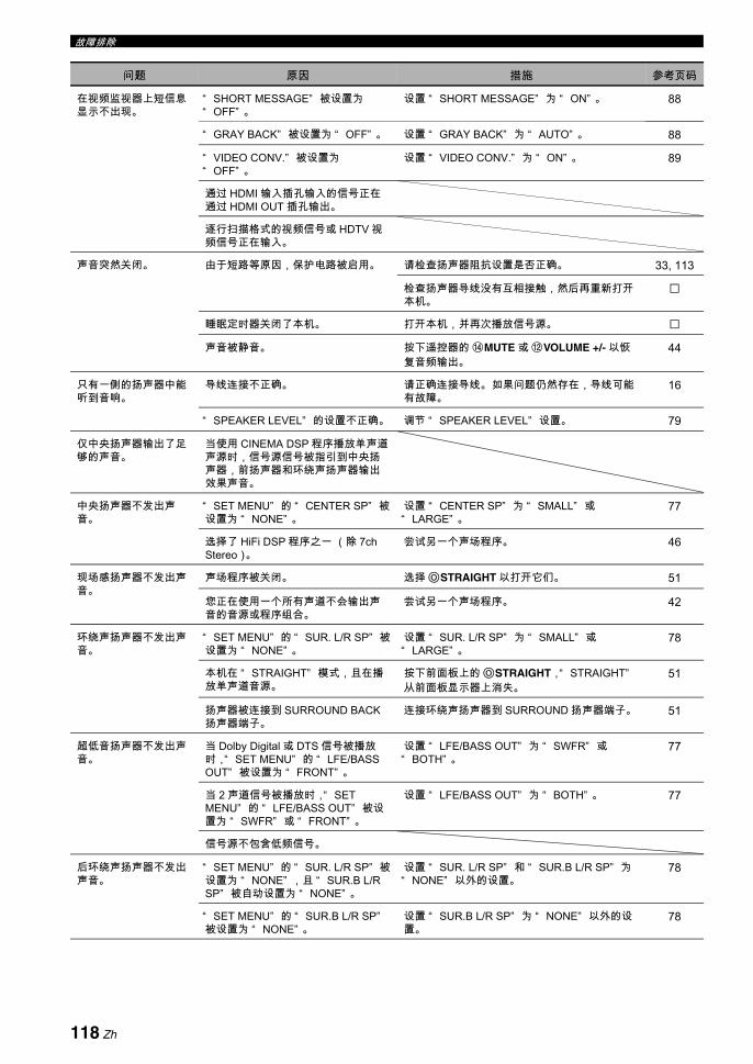
故障排除
在视频监视器上短信息显示不出现。
“ SHORT MESSAGE” 被设置为“ OFF” 。
设置 “ SHORT MESSAGE” 为 “ ON” 。 88
“ GRAY BACK” 被设置为 “ OFF” 。 设置 “ GRAY BACK” 为 “ AUTO” 。 88
“ VIDEO CONV.” 被设置为“ OFF” 。
设置 “ VIDEO CONV.” 为 “ ON” 。 89
通过 HDMI 输入插孔输入的信号正在通过 HDMI OUT 插孔输出。
逐行扫描格式的视频信号或 HDTV 视频信号正在输入。
声音突然关闭。 由于短路等原因,保护电路被启用。 请检查扬声器阻抗设置是否正确。 33, 113
检查扬声器导线没有互相接触,然后再重新打开本机。
睡眠定时器关闭了本机。 打开本机,并再次播放信号源。
声音被静音。 按下遥控器的 DMUTE 或 BVOLUME +/- 以恢复音频输出。
44
只有一侧的扬声器中能听到音响。
导线连接不正确。 请正确连接导线。 如果问题仍然存在,导线可能有故障。
16
“ SPEAKER LEVEL” 的设置不正确。 调节 “ SPEAKER LEVEL” 设置。 79
仅中央扬声器输出了足够的声音。
当使用 CINEMA DSP 程序播放单声道声源时,信号源信号被指引到中央扬声器,前扬声器和环绕声扬声器输出效果声音。
中央扬声器不发出声音。
“ SET MENU” 的 “ CENTER SP” 被设置为 “ NONE” 。
设置 “ CENTER SP” 为 “ SMALL” 或“ LARGE” 。
77
选择了 HiFi DSP 程序之一 (除 7ch Stereo)。
尝试另一个声场程序。 46
现场感扬声器不发出声音。
声场程序被关闭。 选择OSTRAIGHT 以打开它们。 51
您正在使用一个所有声道不会输出声音的音源或程序组合。
尝试另一个声场程序。 42
环绕声扬声器不发出声音。
“ SET MENU” 的 “ SUR. L/R SP” 被设置为 “ NONE” 。
设置 “ SUR. L/R SP” 为 “ SMALL” 或“ LARGE” 。
78
本机在 “ STRAIGHT” 模式,且在播放单声道音源。
按下前面板上的OSTRAIGHT,“ STRAIGHT”从前面板显示器上消失。
51
扬声器被连接到 SURROUND BACK扬声器端子。
连接环绕声扬声器到 SURROUND 扬声器端子。 51
超低音扬声器不发出声音。
当 Dolby Digital 或 DTS 信号被播放时,“ SET MENU” 的 “ LFE/BASS OUT” 被设置为 “ FRONT” 。
设置 “ LFE/BASS OUT” 为 “ SWFR” 或“ BOTH” 。
77
当 2 声道信号被播放时,“ SET MENU” 的 “ LFE/BASS OUT” 被设置为 “ SWFR” 或 “ FRONT” 。
设置 “ LFE/BASS OUT” 为 “ BOTH” 。 77
信号源不包含低频信号。
后环绕声扬声器不发出声音。
“ SET MENU” 的 “ SUR. L/R SP” 被设置为 “ NONE” ,且 “ SUR.B L/R SP” 被自动设置为 “ NONE” 。
设置 “ SUR. L/R SP” 和 “ SUR.B L/R SP” 为“ NONE” 以外的设置。
78
“ SET MENU” 的 “ SUR.B L/R SP”被设置为 “ NONE” 。
设置 “ SUR.B L/R SP” 为 “ NONE” 以外的设置。
78
问题 原因 措施 参考页码
118 Zh

故障排除中
文补
充信
息
无法以期望的数码音频信号格式播放音频输入源。 (在前面板显示器上期望的输入源指示灯或解码器指示灯都不点亮。)
连接的组件机没有设置到输出期望的数码音频信号。
遵照使用说明书,为您的组件机进行适当的设置。
音频输入插孔选择设置在“ ANALOG” 。
设置音频输入插孔选择到 “ AUTO” 。 43
能听到蜂鸣声。 导线连接不正确。 请稳固连接音频导线。 如果问题仍然存在,导线可能有故障。
电唱机没有连接到 GND 端子。 连接电唱机的接地线到本机的 GND 端子。 28
当正在播放录制的节目时音量低。
播放唱片的电唱机具有 MC 拾音头。 通过 MC 拾音头放大器连接电唱机到本机。 28
不能增加音量,或声音失真。
连接到本机的 AUDIO OUT (REC) 插孔的组件机被关闭。
打开组件机的电源。
不能录制声音效果。 不能用一个录制组件机来录制声音效果。
一个信号源不能使用连接到此 DIGITAL OUTPUT 插孔的数码录制组件机来录制。
信号源装置没有连接到本机的DIGITAL INPUT 插孔。
将信号源连接到 DIGITAL INPUT 插孔上。 25, 28
一些装置不能录制 Dolby Digital 或DTS 信号源。
一个信号源不能使用连接到此 AUDIO OUT (REC) 插孔的模拟组件机来录制。
信号源装置没有连接到模拟 AUDIO IN插孔。
将信号源组件机连接到模拟 AUDIO IN 插孔上。 28
本机的声场参数和一些其它设置不能改变。
“ SET MENU” 的 “ MEMORY GUARD” 被设置为 “ ON” 。
设置 “ MEMORY GUARD” 为 “ OFF” 。 90
本机操作不正常。 内部麦克风被外部电击 (例如闪电或过量静电)或低电压的电源供应所冻结。
从 AC 电源插座断开电源导线,在大约 30 秒钟后再次插入。
“ CHECK SP WIRES”出现在前面板显示器中。
扬声器导线短路。 确保所有扬声器导线连接正确。 16
存在来自数码或无线电频率设备的噪音干扰。
本机太靠近数码或高频设备。 将本机移离此类设备。
图像失真。 视频源使用扰频或编码信号防止复制。
本机突然进入待机模式。
内部温度变得过高,过热保护电路被启用。
请等待 1 小时冷却本机,然后重新打开它。
问题 原因 措施 参考页码
119 Zh
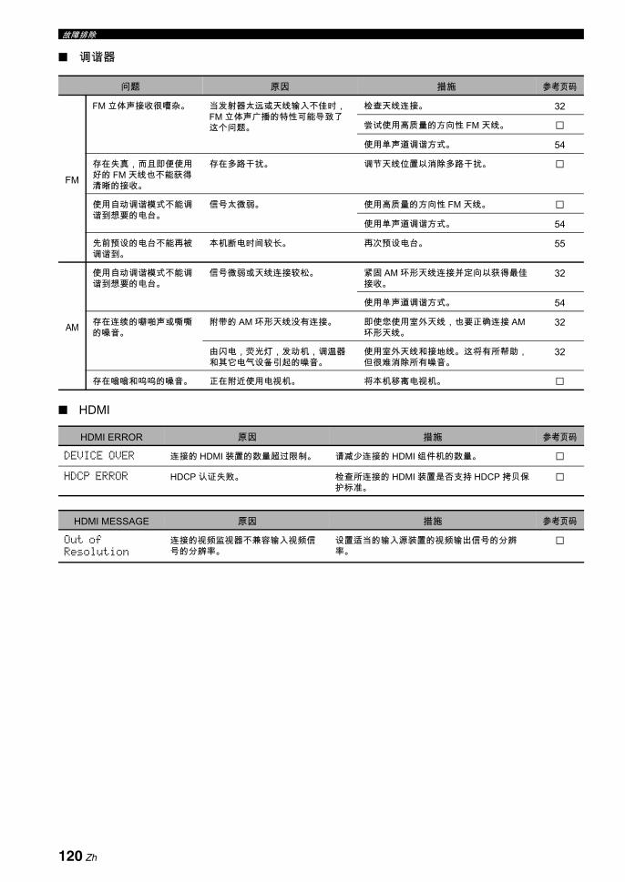
故障排除
调谐器
HDMI
问题 原因 措施 参考页码
FM
FM 立体声接收很嘈杂。 当发射器太远或天线输入不佳时,FM 立体声广播的特性可能导致了这个问题。
检查天线连接。 32
尝试使用高质量的方向性 FM 天线。
使用单声道调谐方式。 54
存在失真,而且即便使用好的 FM 天线也不能获得清晰的接收。
存在多路干扰。 调节天线位置以消除多路干扰。
使用自动调谐模式不能调谐到想要的电台。
信号太微弱。 使用高质量的方向性 FM 天线。
使用单声道调谐方式。 54
先前预设的电台不能再被调谐到。
本机断电时间较长。 再次预设电台。 55
AM
使用自动调谐模式不能调谐到想要的电台。
信号微弱或天线连接较松。 紧固 AM 环形天线连接并定向以获得 佳接收。
32
使用单声道调谐方式。 54
存在连续的噼啪声或嘶嘶的噪音。
附带的 AM 环形天线没有连接。 即使您使用室外天线,也要正确连接 AM环形天线。
32
由闪电,荧光灯,发动机,调温器和其它电气设备引起的噪音。
使用室外天线和接地线。这将有所帮助,但很难消除所有噪音。
32
存在嗡嗡和呜呜的噪音。 正在附近使用电视机。 将本机移离电视机。
HDMI ERROR 原因 措施 参考页码
DEVICE OVER 连接的 HDMI 装置的数量超过限制。 请减少连接的 HDMI 组件机的数量。
HDCP ERROR HDCP 认证失败。 检查所连接的 HDMI 装置是否支持 HDCP 拷贝保护标准。
HDMI MESSAGE 原因 措施 参考页码
Out of Resolution
连接的视频监视器不兼容输入视频信号的分辨率。
设置适当的输入源装置的视频输出信号的分辨率。
120 Zh
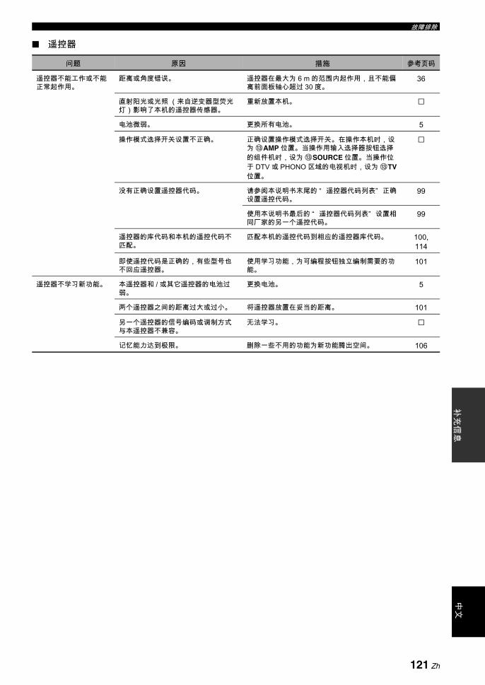
故障排除中
文补
充信
息
遥控器
问题 原因 措施 参考页码
遥控器不能工作或不能正常起作用。
距离或角度错误。 遥控器在 大为 6 m 的范围内起作用,且不能偏离前面板轴心超过 30 度。
36
直射阳光或光照 (来自逆变器型荧光灯)影响了本机的遥控器传感器。
重新放置本机。
电池微弱。 更换所有电池。 5
操作模式选择开关设置不正确。 正确设置操作模式选择开关。在操作本机时,设为 CAMP 位置。当操作用输入选择器按钮选择的组件机时,设为 CSOURCE 位置。当操作位于 DTV 或 PHONO 区域的电视机时,设为 CTV位置。
没有正确设置遥控器代码。 请参阅本说明书末尾的 “ 遥控器代码列表” 正确设置遥控代码。
99
使用本说明书 后的 “ 遥控器代码列表” 设置相同厂家的另一个遥控代码。
99
遥控器的库代码和本机的遥控代码不匹配。
匹配本机的遥控代码到相应的遥控器库代码。 100, 114
即使遥控代码是正确的,有些型号也不回应遥控器。
使用学习功能,为可编程按钮独立编制需要的功能。
101
遥控器不学习新功能。 本遥控器和 / 或其它遥控器的电池过弱。
更换电池。 5
两个遥控器之间的距离过大或过小。 将遥控器放置在妥当的距离。 101
另一个遥控器的信号编码或调制方式与本遥控器不兼容。
无法学习。
记忆能力达到极限。 删除一些不用的功能为新功能腾出空间。 106
121 Zh
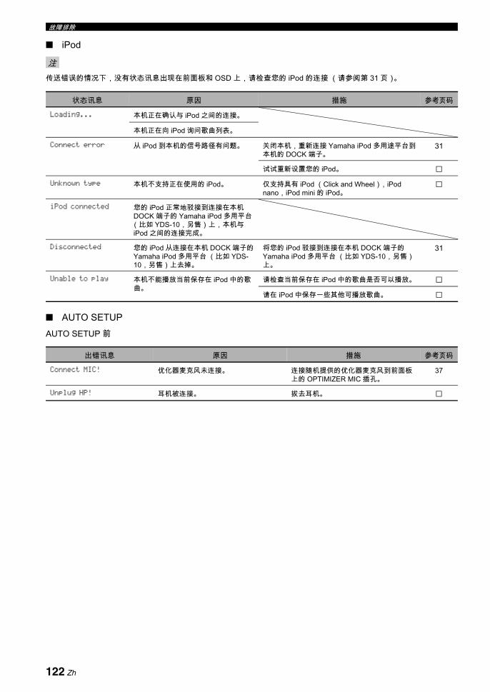
故障排除
iPod
传送错误的情况下,没有状态讯息出现在前面板和 OSD 上,请检查您的 iPod 的连接 (请参阅第 31 页)。
AUTO SETUPAUTO SETUP 前
注
状态讯息 原因 措施 参考页码
Loading... 本机正在确认与 iPod 之间的连接。
本机正在向 iPod 询问歌曲列表。
Connect error 从 iPod 到本机的信号路径有问题。 关闭本机,重新连接 Yamaha iPod 多用途平台到本机的 DOCK 端子。
31
试试重新设置您的 iPod。
Unknown type 本机不支持正在使用的 iPod。 仅支持具有 iPod (Click and Wheel),iPod nano,iPod mini 的 iPod。
iPod connected 您的 iPod 正常地驳接到连接在本机DOCK 端子的 Yamaha iPod 多用平台(比如 YDS-10,另售)上,本机与iPod 之间的连接完成。
Disconnected 您的 iPod 从连接在本机 DOCK 端子的Yamaha iPod 多用平台 (比如 YDS-10,另售)上去掉。
将您的 iPod 驳接到连接在本机 DOCK 端子的Yamaha iPod 多用平台 (比如 YDS-10,另售)上。
31
Unable to play 本机不能播放当前保存在 iPod 中的歌曲。
请检查当前保存在 iPod 中的歌曲是否可以播放。
请在 iPod 中保存一些其他可播放歌曲。
出错讯息 原因 措施 参考页码
Connect MIC! 优化器麦克风未连接。 连接随机提供的优化器麦克风到前面板上的 OPTIMIZER MIC 插孔。
37
Unplug HP! 耳机被连接。 拔去耳机。
122 Zh

故障排除中
文补
充信
息
AUTO SETUP 中
后 AUTO SETUP
• 如果 “ ERROR” 或 “ WARNING” 屏幕出现,请检查问题的原因,然后再次运行 “ AUTO SETUP” 。• 如果出现警告讯息 “ W-2” 或 “ W-3” ,调节虽然进行过,但是,调节不一定 佳。• 根据扬声器的情况,即使扬声器正确连接,警告讯息 “ W-1” 也可能出现。• 如果反复出现 “ E-10” 错误讯息,请联系授权的 Yamaha 服务中心。
出错讯息 原因 措施 参考页码
E-1:NO FRONT SP 前左 / 右声道信号未探测到。 检查前左右扬声器连接。 16
E-2:NO SUR.SP 没有探测到环绕声声道信号。 检查环绕声扬声器连接。 16
E-3:NO PRNS SP 没有探测到现场感声道信号。 检查现场感扬声器连接。 16
E-4:SBR.SBL 仅探测到右后环绕声声道信号。 如果您仅有一个后环绕声扬声器,那么,将这个后环绕声扬声器连接到SURROUND BACK (SINGLE) 扬声器端子。
16
E-5:NOISY 背景噪音太响。 在安静的环境尝试运行 “ AUTO SETUP” 。
关闭噪音电气设备,例如空调或将其从优化器麦克风旁移走。
E-6:CHECK SUR. 后环绕声扬声器被连接,但是环绕声左右扬声器没有连接。
当您使用后环绕声扬声器时,请连接环绕声扬声器。
17
E-7:NO MIC 优化器麦克风在 “ AUTO SETUP” 步骤期间被拔去了。
连接随机提供的优化器麦克风到前面板上的 OPTIMIZER MIC 插孔。
37
E-8:NO SIGNAL 优化器麦克风不探测测试音。 检查麦克风设置。 37
检查扬声器连接和放置。 16
E-9:USER CANCEL 由于用户操作而取消 “ AUTO SETUP”步骤。
再次运行 “ AUTO SETUP” 。 37
E-10:INTERNAL ERROR 内部错误出现。 再次运行 “ AUTO SETUP” 。 37
警告讯息 原因 措施 参考页码
W-1:OUT OF PHASE 扬声器极性不正确。根据扬声器的情况,即使扬声器正确连接,讯息也可能出现。
检查扬声器极性 (+/-)连接是否正确。 16
W-2:OVER 24m (80ft) 扬声器和收听位置之间的距离超过 24 m。
将扬声器放得更靠近收听位置。
W-3:LEVEL ERROR 各个扬声器之间的音量电平差异过大。 重新调节扬声器安装,以便所有扬声器放置的位置情况相似。
检查扬声器连接。 16
使用类似质量的扬声器。
调节该超低音扬声器的输出音量。 37
注
123 Zh

系统复位
使用该功能复位本机的所有参数到工厂初始设置。
• 该过程完全复位本机的所有参数,包括 “ SET MENU” 参数。 但是,高级设置菜单参数不能被初始化。• 工厂初始设置将在下一次打开本机后生效。
y在任何时候,要取消初始化操作而不进行任何改变时,只要按前面板上的AMASTER ON/OFF 到向外的 OFF 位置。
1 按下前面板上的AMASTER ON/OFF 按钮,向外释放到 OFF 位置,关闭本机。
2 按下并保持OSTRAIGHT,然后向内按下AMASTER ON/OFF 到 ON 位置,打开本机。本机打开,“ ADVANCED SETUP” 出现在前面板显示器上。
3 旋转NPROGRAM 选择器,选择“ INITIALIZE” 。
4 反复按OSTRAIGHT 选择 “ ALL” 。
y• 选择 “ CANCEL” 以取消初始化操作,不做任何变
动。• 您可以分别初始化视频参数或声场程序参数。有关详
情请参阅第 116 页。
5 按下AMASTER ON/OFF,向外释放到 OFF 位置,以确认您的选择并关闭本机。
系统复位
注
EFFECT
STRAIGHT
MASTER
在按住的同时
I N I T I A L I Z E
C A N C E L
I N I T I A L I Z E
A L L
124 Zh

术语补
充信
息中
文
音频和视频同步 (口形同步)Lip sync, 口形同步的缩写,是一个涉及到在后期制作和传输过程中,保持音频和视频信号同步的问题和可能性的术语。解决音频和视频的时间差问题需要终端用户进行复杂的调节。HDMI V1.3 引进了自动音频和视频同步的技术,使得机器可以自动且准确地进行同步而不须用户干涉。
双重放大连接双重放大连接对于一个扬声器使用两组放大器。一组放大器连接到扬声器的低音部分,另一组则连接到混合的中音和高音部分。通过这样的排列,每个放大器只操作有限的频率范围。这个有限范围使得每个放大器的工作更简单,每个放大器就可能在某种程度上减少其对声音的影响。扬声器的内部分频包括 LPF(低音通过过滤器)和 HPF (高音通过过滤器)。像它的名称所意味的一样,LPF 使频率低于切断频率的通过,使频率高于切断频率的不通过。同样,HPF 使频率高于其切断频率的通过。
分量视频信号使用分量视频信号时,视频信号被分隔成亮度的 Y 信号以及色度的 PB 信号和 PR 信号。由于每个这些信号都是独立的,使用此系统能更真实地再现色彩。由于从色彩信号中减去了亮度信号,分量信号也被称为“ 色差信号” 。需要一个有分量输入插孔的监视器,以输出分量信号。
复合视频信号使用复合视频信号系统时,视频信号包含三种基本视频图像元素:色彩,亮度和同步数据。视频组件机上的复合视频插孔传输这三个合并的元素。
Deep ColorDeep Color (深度彩色)表示在显示器上使用不同的彩色深度,根据以前的 HDMI 版本的不同,可以比24- 比特更高。这些多余的比特深度使得 HDTV 和其他显示器从数百万种颜色走向数十亿种颜色,这可以消除屏幕上的色带问题,得到更加光滑的色相过渡以及精细的颜色渐变。增加的反差比可以在黑白之间表现出更多倍的灰色阴影。此外,深度彩色也在 RGB或 YCbCr 彩色空间的区间内提供了更多的颜色数目。
对话标准化对话标准化是 Dolby Digital 或 DTS 的特性,被用于将节目保持在相同的平均收听水平,因此,用户就不必在 Dolby Digital 或 DTS 节目之间改变音量控制。
Dolby DigitalDolby Digital 是一种数码环绕声系统,能给您完全独立的多声道音频。Dolby Digital 有 3 个前声道 (前方左 / 右、中)和 2 个环绕声立体声声道,能提供 5 个完全范围的音频声道。它有一个专用于称为 LFE(低频效果)低频效果的额外声道,此系统一共有5.1 声道 (LFE 被算成 0.1 声道)。通过对于环绕声扬声器使用 2 声道立体声,它比 Dolby Surround 能提供更精确的移动声音效果和环绕声环境。由 5 个完全范围的声道再现的宽广动态范围 (从 大到 小音量)以及使用数码声音处理所产生的精确声音定位,能给听者提供前所未有的激动感和现场感。 使用本机能自由选择从单声道到 5.1 声道配置的任何声音环境,以供您欣赏。
Dolby Digital EXDolby Digital EX 创建来自 5.1 声道信号源的 6 个完整波段输出声道。 使用能从原始录音的 2 个环绕声中导出 3 个环绕声声道的一个矩阵解码器,能做到这点。要获得 佳结果,对于用 Dolby Digital Surround EX 录制的电影声轨,应该使用 Dolby Digital EX。有了这个额外的声道,您能感受更动感更身临其境的运动声音,特别是对于那些有 “ 头顶飞过” 和 “ 环绕飞行” 效果的场景。
术语
125 Zh
术语
Dolby Digital PlusDolby Digital Plus 是一种高级音频技术,用于高清晰度节目和媒体,包括 HD 广播, HD DVD 以及蓝光碟片。 作为 HD DVD 的强制性音频标准以及蓝光碟片的可选音频标准,该技术可以独立的声道输出传送多声道音响。Dolby Digital Plus 支持的比特率 高可达6.0 Mbps, 可以同时携带 7.1 个独立的音频声道。 Dolby Digital Plus 支持 HDMI V1.3,是未来的光碟播放机以及 AV 接收机 / 放大机的既定技术,同时又完全兼容现有的包括 Dolby Digital 的多声道音频系统。
Dolby Pro Logic IIDolby Pro Logic II 是用于解码大量现存 Dolby Surround 音源的改进的技术。这一新技术使用 5 个独立的声道播放,包括 2 个前方左右声道,1 个中央声道和 2 个环绕声左右声道,而传统的 Pro Logic 技术只有 1 个环绕声声道。 有 3 种模式: 用于音乐音源的 “ Music 模式” ;用于电影音源的 “ Movie 模式”和用于游戏音源的 “ Game 模式” 。
Dolby Pro Logic IIxDolby Pro Logic IIx 是一项新技术,它能从 2 声道或多声道声源进行分散的多声道播放。有 3 种模式: 用于音乐音源的 “ Music 模式” ;用于电影音源 (仅限于 2 声道)的 “ Movie 模式” 和用于游戏音源的“ Game 模式” 。
Dolby SurroundDolby Surround 使用 4 声道模拟录制系统,以再现富有现场感的动态声音效果 : 2 个前左和右声道 (立体声),一个中央声道用于对话 (单声道),一个环绕声声道用于特殊声音效果 (单声道)。环绕声声道再现一个狭窄频率范围内的声音。Dolby Surround 被几乎所有视频磁带、光盘以及许多电视机和有线广播所广泛使用。本机内置的 Dolby Pro Logic 解码器采用一种数码信号处理系统,能自动稳定每个声道的音量,以增强移动的声音效果和方向性。
Dolby TrueHDDolby TrueHD 是一种高级的无损失音频技术,用于高清晰度碟片为基础的媒体,包括 HD DVD 以及蓝光碟片。作为 HD DVD 的强制性音频标准以及蓝光碟片的可选音频标准,该技术可以将演播室的原版逐字节地真实传送成音响,造成一种高清晰度的家庭影院环境。Dolby TrueHD 支持的比特率 高可达18.0 Mbps, 可以同时携带 8 个独立的 24-bit/96 kHz音频声道。 Dolby TrueHD 支持 HDMI V1.3,是未来的光碟播放机以及 AV 接收机 / 放大机的既定技术,同时又完全兼容现有的多声道音频系统,维持 Dolby Digital 的元数据功能,并支持对话标准化和动态范围控制。
DSD直接数据流数码 (DSD)技术在数码存储媒体上存储音频信号,例如 SACD。使用 DSD,在 2.8224 MHz 的高频取样率以单一的比特值存储信号,使用噪音成形和超取样减少失真,具有音频信号的极高量子化的特点。由于该高取样率,可以获得比用于普通音频 CD 的 PCM 格式更高的音频质量。
DTS 96/24DTS 96/24 提供了史无前例的用于 DVD 视频多声道声音的音频质量,并且向后兼容所有的 DTS 解码器。 “ 96” 指的是 96 kHz 取样比率,相对于 48 kHz 的取样频率而言。“ 24” 是指 24 位单词长度。DTS 96/24提供对初始的 96/24 主机、用于音乐程序具有完整质量和完整动感的视频的 96/24 5.1 声道声音以及 DVD视频上的动感图像声轨透明的声音质量。
126 Zh

术语中
文补
充信
息
DTS Digital SurroundDTS 数码环绕声使用 6.1 声道数码声轨来替换电影的模拟声轨,现在正迅速在全球影院中受到欢迎。DTS, Inc. 开发了一个家庭影院系统,使您能在自己家中就欣赏到 DTS 数码环绕声的声音厚度和自然空间再现。 此系统产生了几乎无失真的 6 声道声音 (从技术上说,前左右声道,中央声道,环绕声左右声道,和一个 LFE 0.1 (超低音扬声器)声道,总共是 5.1 个声道)。本机包含 DTS-ES 解码器,能通过在现有的5.1 声道格式上增加后环绕声声道,再现 6.1 声道。
DTS ExpressDTS Express 是一种高级音频技术,是蓝光碟片或HD DVD 的可选技术,可为网络数据流和互联网应用提供高质量、低比特率的音频优化。DTS Express 可作为蓝光碟片的次级音频特性或 HD DVD 副音频特性。 这些特性可以根据需要,通过互联网等传输音频解说 (例如,电影中解说员的台词等)。DTS Express 信号在播放机上被混合到主音频流,然后通过数字同轴、数字光纤或模拟连接,再将混合的音频流传送到 AV 接收机 / 放大器。
DTS-HD High Resolution AudioDTS-HD High Resolution Audio 是一种高清晰度音频技术,用于高清晰度碟片为基础的媒体,包括 HD DVD 以及蓝光碟片。作为 HD DVD 以及蓝光碟片的可选音频标准,该技术可以传送与音源实质上不可区分的音响,造成一种高清晰度的家庭影院环境。DTS-HD High Resolution Audio 支持的比特率 高可达3.0 Mbps, 用于 HD DVD,或 6.0 Mbps, 用于蓝光碟片;可以同时携带 多 7.1 个独立的 24-bit/96 kHz 音频声道。DTS-HD High Resolution Audio 支持HDMI V1.3,是未来的光碟播放机以及 AV 接收机 /放大机的既定技术,同时又完全兼容现有的包括DTS Digital Surround 的多声道音频系统。
DTS-HD Master AudioDTS-HD Master Audio 是一种高级的无损失音频技术,用于高清晰度碟片为基础的媒体,包括 HD DVD以及蓝光碟片。作为 HD DVD 以及蓝光碟片的强制性音频标准,该技术可以将演播室的原版逐字节地真实传送成音响,造成一种高清晰度的家庭影院环境。 DTS-HD Master Audio 支持的比特率 高可达18.0 Mbps, 用于 HD DVD,或 24.5 Mbps, 用于蓝光碟片;可以同时携带 多 7.1 个独立的 24-bit/96 kHz音频声道。 DTS-HD Master Audio 支持 HDMI V1.3,是未来的光碟播放机以及 AV 接收机的既定技术,同时又完全兼容现有的包括 DTS Digital Surround 的多声道音频系统。
HDMIHDMI (High-Definition Multimedia Interface,高分辨率多媒体界面)是第一个业界支持的,非压缩,全数码音频 / 视频界面。可提供任意源 (比如顶置盒或AV 接收机)和音频 / 视频监视器 (比如数码电视)之间的界面,HDMI 支持标准的,加强的或高分辨率的视频以及多声道数码音频,仅使用一根缆线。当与 HDCP (High-bandwidth Digital Content Protection,高带宽数码内容保护)共用时,HDMI 提供安全的韵音频 / 视频界面,可以满足提供商以及系统操作要求的内容安全保护。关于 HDMI 的进一步信息,请参考 HDMI 的网站,“ http://www.hdmi.org/” 。
LFE 0.1 声道该声道再现低频信号。此声道的频率范围是 20 Hz 到120 Hz。 此声道被算作 0.1 声道,因为在 Dolby Digital 或 DTS 5.1/6.1 声道系统中,相比其它5/6 声道再现的完整范围,它仅增强低频范围。
Neo:6Neo:6 通过特定的解码器将传统的 2 声道声源解码为6 声道播放。它使您以具有更高的分隔度的完整范围的声道进行播放,就好象数码分离信号播放。有两种模式:用于音乐音源的 “ Music 模式” ;用于电影音源的 “ Cinema 模式” 。
127 Zh
术语
PCM (线性 PCM)线性 PCM 是一种信号格式,在此格式下能在不使用任何压缩的情况下,对模拟音频信号进行数码化、录制和传输。这作为录制 CD 和 DVD 音频的一种方式而使用。PCM 系统使用一种技术,用来在很小的时间单位中对模拟信号的尺寸进行取样 代表 “ 脉冲代码调制” ,模拟信号被作为脉冲而编码,然后被调制以供录制。
取样频率和量化比特的数量当数码化一个模拟音频信号时,每秒钟取样信号的次数被称为取样频率,而当将声音水平转化为数字值时的精确度被称为量化比特数量。 能播放的数率的范围基于取样频率而决定,而代表声音水平差异的动态范围由量化比特数量而决定。原则上说,取样频率越高,能被播放的频率范围越宽,而量化比特的数量越高,能再现的声音水平的质量越高。
S 视频信号使用 S 视频信号系统时,使用针口导线,通常将视频信号通过 S 视频导线分隔和传输,Y 信号用于亮度,C 信号用于色度。使用 S VIDEO 插孔消除视频信号传输中的损耗,能录制和播放更美丽的图像。
128 Zh

声场程序信息补
充信
息中
文
声场的要素真正创建生动、丰富而完整音调的是来自房间的墙面的多次反射。除了使声音生动,这些反射也使我们能够辨别播放机所处的位置以及我们坐着的房间的尺寸和形状。除了来自播放机设备直接进入我们耳朵的声音外,还有两类有明显特性的声音反射组成了声场。
早期反射反射的声音在仅经过一次表面反射后 ( 例如从墙面或天花板)就极快地进入我们的耳朵 (直接声音后 50毫秒到 100 毫秒)。早期反射实际上增加了直接声音的清晰度。
回响这是经过一个以上表面的反射 (例如从墙面,和 / 或天花板)而产生的,由于反射次数多,它们被混合在一起,组成连续的声音的余辉。它们是无方向性的,而且减弱了直接声音的清晰度。
直接的声音,早期反射和其后的回响组合在一起,帮助我们决定主观感觉到的房间尺寸和形状,正是由数码声场处理器再现的此信息帮助创建了声场。
如果您能在收听的房间中创建适当的早期反射和其后的回响,您就能创建您自己的收听环境。您的房间的声音特性可以被改变成交响乐厅、舞厅或虚拟中的任何尺寸的房间的声音特性。此随意创建声场的能力正是 Yamaha 采用数码声场处理器所达到的。
CINEMA DSP由于 Dolby Surround 和 DTS 系统原先是设计用于电影院的,在拥有许多扬声器和为声音效果而设计的剧院中能感受到 佳效果。由于家庭的条件,例如房间尺寸,墙面材料,扬声器数量等可能有很大的不同,听到的声音也不可避免地有所不同。根据实际测量到的大量数据,Yamaha CINEMA DSP 使用 Yamaha原始声场技术,结合各种数字音频系统,在您自己家中的收听室中,提供影院般的视觉和听觉享受。
SILENT CINEMAYamaha 开发了一种针对耳机的自然的现场感的声音效果 DSP 算法。为每个声场设置了针对耳机的参数,以在耳机中欣赏所有声场程序的精确再现。
Virtual CINEMA DSPYamaha 开发了 Virtual CINEMA DSP 算法,使您能使用虚拟环绕声扬声器,在没有任何环绕声扬声器的情况下,欣赏 DSP 声场的环绕声效果。也可在不包含中央扬声器而 少只有两个扬声器的系统中,欣赏Virtual CINEMA DSP。
Compressed Music Enhancer本机的 Compressed Music Enhancer 功能可以通过弥补压缩缺陷带来的和声不足,增强您的听觉氛围。结果,因为高频保真丧失以及低频丧失的低频缺乏造成的单调综合症得到补偿,从而改善了整个音响系统的性能。
来自各个扬声器的声音输出依照正在输入的音频信号的类型从各个扬声器输出声音。参考下表中的图表来理解每个声场程序的扬声器布局。有关在声场程序来自各个扬声器的声音输出的详情,请参阅本说明书末尾的 “ 附录” 中的 “ 各声场程序的声音输出” 。
根据正在播放的输入音源的类型,请注意,某些扬声器中也许没有声音或声音不足。而且,也许有些声道被调节到电影的特定方面时,例如专门的声音效果等等,这些声道就只有一部分可以使用。
y除 “ 2ch Stereo” , “ 7ch Stereo” ,和 “ STRAIGHT” 以外,您可以选择一个解码器以便从后环绕声扬声器输出声音( 请参阅第 46 页 )。
声场程序信息
注
129 Zh

参数均衡器信息
本机使用 Yamaha Parametric Room Acoustic Optimizer (YPAO) 技术,可以优化其参数均衡器的频率特性来匹配您的收听环境。YPAO 使用以下三个参数 ( 频率,增益和 Q 因子 ) 的组合以提供高度精确的频率特性调节。
频率该参数能够以 1/3 八度音阶递增,在 32 Hz 和 16 kHz之间调节。
增益该参数能够以 0.5dB 递增,在 -20 到 +6dB 之间调节。
Q 因子指定的频率波段的宽度被称为 Q factor。该参数可以在 0.5 到 10 之间调节。
YPAO 使用以上三个参数 ( 频率,增益和 Q 因子 ) 的组合来调节频率特性以适应您的收听要求,这三个参数适用于本机的参数均衡器内的每一个均衡波段。对于每个声道,本机有 7 个均衡器波段。多均衡器波段的使用可以对频率特性进行更精确的调节 ( 如图 2)。使用单一的均衡器波段是不可能的 ( 如图 1)。
图 1
图 2
参数均衡器信息
增益
频率
初始频率特性
波段 1修正后的频率特性
增益
频率
波段 1
波段 2
修正后的频率特性
初始频率特性
130 Zh
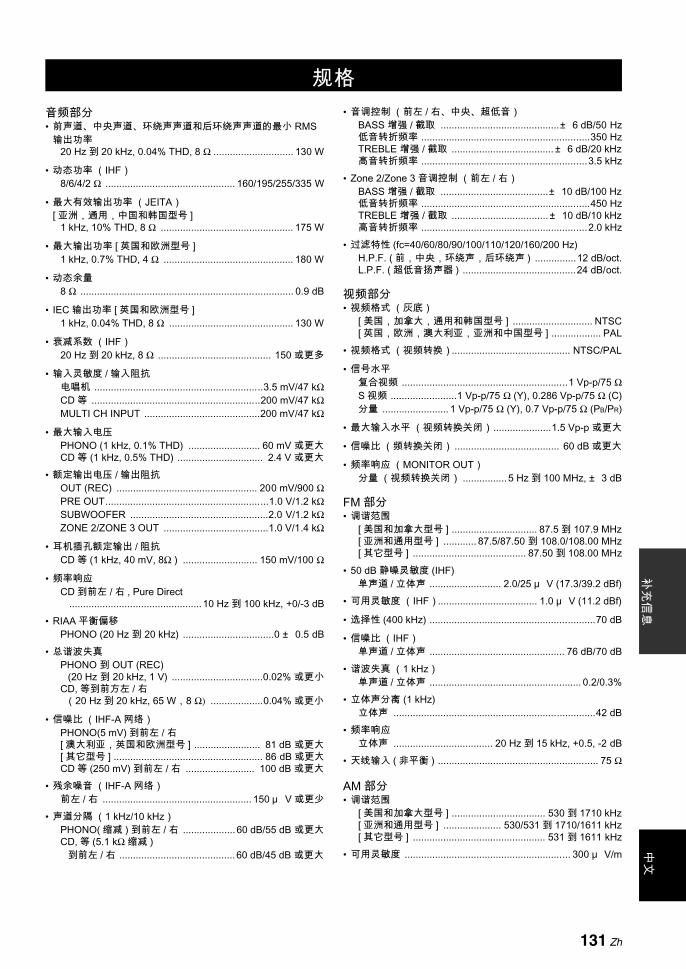
规格补
充信
息中
文
音频部分• 前声道、中央声道、环绕声声道和后环绕声声道的 小 RMS
输出功率20 Hz 到 20 kHz, 0.04% THD, 8 Ω ............................. 130 W
• 动态功率 (IHF)8/6/4/2 Ω ............................................... 160/195/255/335 W
• 大有效输出功率 (JEITA) [ 亚洲,通用,中国和韩国型号 ]
1 kHz, 10% THD, 8 Ω ................................................ 175 W
• 大输出功率 [ 英国和欧洲型号 ]1 kHz, 0.7% THD, 4 Ω ............................................... 180 W
• 动态余量8 Ω ............................................................................. 0.9 dB
• IEC 输出功率 [ 英国和欧洲型号 ]1 kHz, 0.04% THD, 8 Ω ............................................. 130 W
• 衰减系数 (IHF)20 Hz 到 20 kHz, 8 Ω ......................................... 150 或更多
• 输入灵敏度 / 输入阻抗电唱机 .............................................................3.5 mV/47 kΩCD 等 .............................................................200 mV/47 kΩMULTI CH INPUT ..........................................200 mV/47 kΩ
• 大输入电压PHONO (1 kHz, 0.1% THD) .......................... 60 mV 或更大CD 等 (1 kHz, 0.5% THD) ............................... 2.4 V 或更大
• 额定输出电压 / 输出阻抗OUT (REC) ................................................... 200 mV/900 ΩPRE OUT...........................................................1.0 V/1.2 kΩSUBWOOFER ..................................................2.0 V/1.2 kΩZONE 2/ZONE 3 OUT ......................................1.0 V/1.4 kΩ
• 耳机插孔额定输出 / 阻抗CD 等 (1 kHz, 40 mV, 8Ω ) ........................... 150 mV/100 Ω
• 频率响应CD 到前左 / 右 , Pure Direct
................................................10 Hz 到 100 kHz, +0/-3 dB• RIAA 平衡偏移
PHONO (20 Hz 到 20 kHz) .................................0 ± 0.5 dB• 总谐波失真
PHONO 到 OUT (REC) (20 Hz 到 20 kHz, 1 V) .................................0.02% 或更小
CD, 等到前方左 / 右 (20 Hz 到 20 kHz, 65 W,8 Ω) ...................0.04% 或更小
• 信噪比 (IHF-A 网络)PHONO(5 mV) 到前左 / 右[ 澳大利亚,英国和欧洲型号 ] ........................ 81 dB 或更大[ 其它型号 ] ...................................................... 86 dB 或更大CD 等 (250 mV) 到前左 / 右 ......................... 100 dB 或更大
• 残余噪音 (IHF-A 网络)前左 / 右 ...................................................... 150 μ V 或更少
• 声道分隔 (1 kHz/10 kHz)PHONO( 缩减 ) 到前左 / 右 ...................60 dB/55 dB 或更大CD, 等 (5.1 kΩ 缩减 )
到前左 / 右 ..........................................60 dB/45 dB 或更大
• 音调控制 (前左 / 右、中央、超低音)BASS 增强 / 截取 ...........................................± 6 dB/50 Hz低音转折频率 .............................................................350 HzTREBLE 增强 / 截取 ..................................... ± 6 dB/20 kHz高音转折频率 ............................................................3.5 kHz
• Zone 2/Zone 3 音调控制 (前左 / 右)BASS 增强 / 截取 .......................................± 10 dB/100 Hz低音转折频率 .............................................................450 HzTREBLE 增强 / 截取 ...................................± 10 dB/10 kHz高音转折频率 ............................................................2.0 kHz
• 过滤特性 (fc=40/60/80/90/100/110/120/160/200 Hz)H.P.F. ( 前,中央,环绕声,后环绕声 ) ...............12 dB/oct.L.P.F. ( 超低音扬声器 ) .........................................24 dB/oct.
视频部分• 视频格式 (灰底)
[ 美国,加拿大,通用和韩国型号 ] ............................. NTSC[ 英国,欧洲,澳大利亚,亚洲和中国型号 ] .................. PAL
• 视频格式 (视频转换)........................................... NTSC/PAL
• 信号水平复合视频 ............................................................1 Vp-p/75 ΩS 视频 ........................1 Vp-p/75 Ω (Y), 0.286 Vp-p/75 Ω (C)分量 ........................ 1 Vp-p/75 Ω (Y), 0.7 Vp-p/75 Ω (PB/PR)
• 大输入水平 (视频转换关闭) .....................1.5 Vp-p 或更大
• 信噪比 (频转换关闭) ...................................... 60 dB 或更大
• 频率响应 (MONITOR OUT)分量 (视频转换关闭) ................ 5 Hz 到 100 MHz, ± 3 dB
FM 部分• 调谐范围
[ 美国和加拿大型号 ] ............................... 87.5 到 107.9 MHz[ 亚洲和通用型号 ] ............ 87.5/87.50 到 108.0/108.00 MHz[ 其它型号 ] ......................................... 87.50 到 108.00 MHz
• 50 dB 静噪灵敏度 (IHF)单声道 / 立体声 .......................... 2.0/25 μ V (17.3/39.2 dBf)
• 可用灵敏度 (IHF).................................... 1.0 μ V (11.2 dBf)
• 选择性 (400 kHz) ............................................................70 dB
• 信噪比 (IHF)单声道 / 立体声 ................................................. 76 dB/70 dB
• 谐波失真 (1 kHz)单声道 / 立体声 ....................................................... 0.2/0.3%
• 立体声分离 (1 kHz) 立体声 .........................................................................42 dB
• 频率响应 立体声 .................................... 20 Hz 到 15 kHz, +0.5, -2 dB
• 天线输入 ( 非平衡 ) .......................................................... 75 Ω
AM 部分• 调谐范围
[ 美国和加拿大型号 ] .................................. 530 到 1710 kHz[ 亚洲和通用型号 ] ..................... 530/531 到 1710/1611 kHz[ 其它型号 ] ................................................ 531 到 1611 kHz
• 可用灵敏度 ............................................................ 300 μ V/m
规格
131 Zh
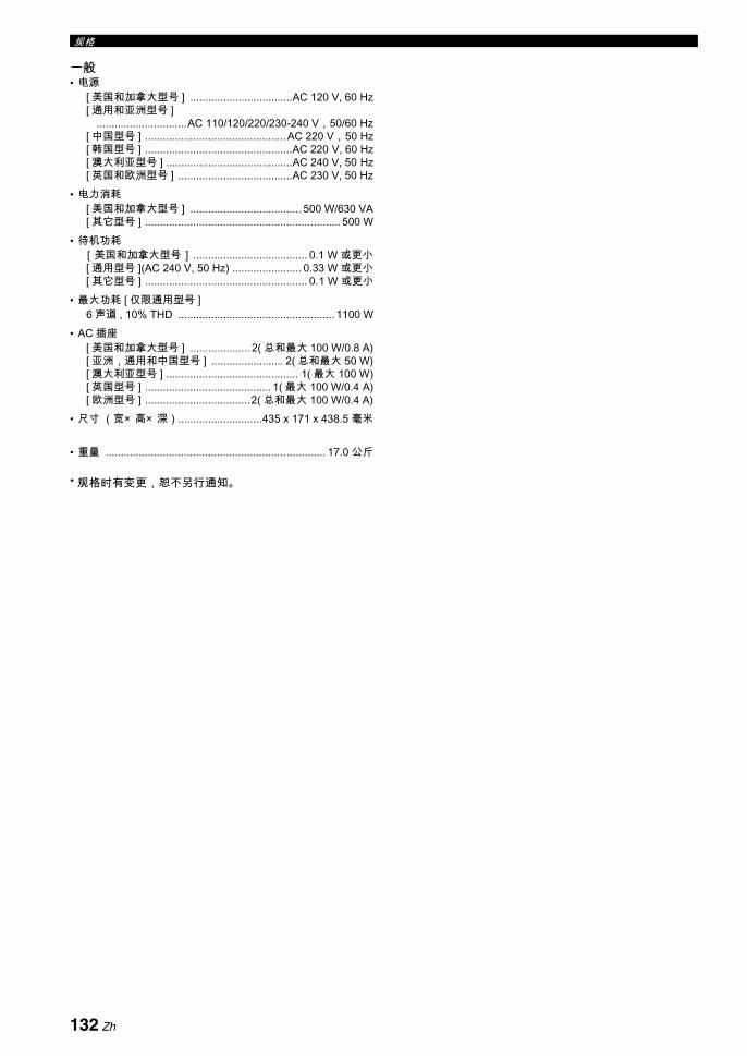
规格
一般• 电源
[ 美国和加拿大型号 ] ..................................AC 120 V, 60 Hz[ 通用和亚洲型号 ]
..............................AC 110/120/220/230-240 V,50/60 Hz[ 中国型号 ] ...............................................AC 220 V,50 Hz[ 韩国型号 ] .................................................AC 220 V, 60 Hz[ 澳大利亚型号 ] ..........................................AC 240 V, 50 Hz[ 英国和欧洲型号 ] ......................................AC 230 V, 50 Hz
• 电力消耗[ 美国和加拿大型号 ] ..................................... 500 W/630 VA[ 其它型号 ] .................................................................500 W
• 待机功耗[美国和加拿大型号] ...................................... 0.1 W 或更小[ 通用型号 ](AC 240 V, 50 Hz) ....................... 0.33 W 或更小[ 其它型号 ] ...................................................... 0.1 W 或更小
• 大功耗 [ 仅限通用型号 ]6 声道 , 10% THD .................................................... 1100 W
• AC 插座[ 美国和加拿大型号 ] .................... 2( 总和 大 100 W/0.8 A)[ 亚洲,通用和中国型号 ] ........................ 2( 总和 大 50 W)[ 澳大利亚型号 ] ............................................ 1( 大 100 W)[ 英国型号 ] .......................................... 1( 大 100 W/0.4 A)[ 欧洲型号 ] ...................................2( 总和 大 100 W/0.4 A)
• 尺寸 (宽× 高× 深)............................435 x 171 x 438.5 毫米
• 重量 ......................................................................... 17.0 公斤
* 规格时有变更,恕不另行通知。
132 Zh
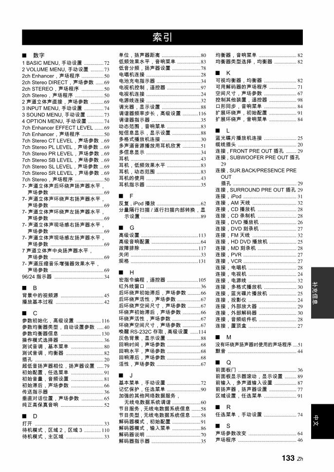
索引中
文补
充信
息
数字1 BASIC MENU, 手动设置 ............... 722 VOLUME MENU, 手动设置 .......... 732ch Enhancer,声场程序 ................. 502ch Stereo DIRECT,声场参数 ...... 692ch STEREO,声场程序 ................. 502ch Stereo,声场程序 ...................... 502 声道立体声直接,声场参数 .......... 693 INPUT MENU, 手动设置 ............... 743 SOUND MENU, 手动设置 ............. 734 OPTION MENU, 手动设置 ............ 747ch Enhancer EFFECT LEVEL ....... 697ch Enhancer,声场程序 ................. 507ch Stereo CT LEVEL,声场参数 .. 697ch Stereo PL LEVEL,声场参数 ... 697ch Stereo PR LEVEL,声场参数 .. 697ch Stereo SB LEVEL,声场参数 .. 697ch Stereo SL LEVEL,声场参数 ... 697ch Stereo SR LEVEL,声场参数 .. 697ch Stereo,声场程序 ...................... 507- 声道立体声后环绕声扬声器水平,
声场参数 ......................................... 697- 声道立体声环绕声右扬声器水平,
声场参数 ......................................... 697- 声道立体声环绕声左扬声器水平,
声场参数 ......................................... 697- 声道立体声现场感右扬声器水平,
声场参数 ......................................... 697- 声道立体声现场感左扬声器水平,
声场参数 ......................................... 697 声道立体声中央扬声器水平,
声场参数 ......................................... 697- 声道压缩音乐增强器效果水平,
声场参数 ......................................... 6996/24 指示器 ...................................... 34
B背景中的视频源 ................................. 45播放基本过程 ..................................... 42
C参数初始化,高级设置 ................... 116参数均衡器类型,自动设置参数 ..... 40参数均衡器信息 ............................... 130操作模式选择器 ................................. 36测试音调,基本菜单 ......................... 80测试音调,均衡器 ............................. 82插孔 ..................................................... 20超低音扬声器相位,扬声器设置 ..... 79初始配置,任选菜单 ......................... 91初始音量,音频设置 ......................... 81初始滞后,声场参数 ......................... 66传送指示器 ......................................... 36垂直对话位置,声场参数 ................. 65纯正高保真音响 ................................. 52
D打开 ..................................................... 33待机模式,区域 2,区域 3 ............. 110待机模式,主区域 ............................. 33
单位,扬声器距离 ..............................80低频效果水平,音响菜单 ..................83低音分频,扬声器设置 ......................78电唱机连接 ..........................................28电池充电指示器 ..................................34电视机控制,遥控器 ..........................97电视机连接 ..........................................24电源线连接 ..........................................32调光器,显示设置 ..............................88调谐器频率步长,高级设置 ............116调谐器指示器 ......................................35动态范围,音响菜单 ..........................83短信息显示,显示设置 ......................88多格式播放机连接 ..............................30多声道音源播放用耳机欣赏 ..............51多信息显示 ..........................................34耳机 ......................................................43耳机,低频效果水平 ..........................83耳机,动态范围 ..................................83耳机的使用 ..........................................43耳机指示器 ..........................................35
F反复 , iPod 播放 ..................................62分量隔行扫描 / 逐行扫描内部转换,显
示设置 ..............................................89
G高级设置 ............................................113高级音响配置 ......................................64故障排除 ............................................117关闭 ......................................................33规格 ....................................................131
H宏指令编程,遥控器 ........................105红外线窗口 ..........................................36后环绕声初始滞后,声场参数 ..........66后环绕声活性,声场参数 ..................67后环绕声空间尺寸,声场参数 ..........67环绕声初始滞后,声场参数 ..............66环绕声活性,声场参数 ......................67环绕声空间尺寸,声场参数 ..............67唤醒 RS-232C 存取 , 高级设置 ......114灰色背景,显示设置 ..........................88回响时间,声场参数 ..........................68回响水平,声场参数 ..........................68回响滞后,声场参数 ..........................68活性,声场参数 ..................................67
J基本菜单,手动设置 ..........................72记忆保护,任选菜单 ..........................90加强的其他网络数据服务,
无线电数据系统调谐 ......................60节目服务 , 无线电数据系统信息 .......58节目类型 , 无线电数据系统信息 .......58解码器模式,初始配置 ......................91解码器模式,输入菜单 ......................86解码器说明 ..........................................70解码器指示器 ......................................35
均衡器,音响菜单 ............................. 82均衡器类型选择,均衡器 ................. 82
K可视均衡器,均衡器 ......................... 82可用解码器的声场程序 ..................... 71空间尺寸,声场参数 ......................... 67控制其他装置,遥控器 ..................... 98口形同步,音响菜单 ......................... 84扩展环绕声,初始配置 ..................... 91扩展环绕声,音响菜单 ..................... 84
L蓝光碟片播放机连接 ......................... 25缆线插头 ............................................. 20连接 , FRONT PRE OUT 插孔 ........ 29连接 , SUBWOOFER PRE OUT 插孔
29连接 , SUR.BACK/PRESENCE PRE
OUT插孔 .................................................. 29
连接 , SURROUND PRE OUT 插孔 29连接, iPod ......................................... 31连接,AM 天线 .................................. 32连接,CD 播放机 .............................. 28连接,CD 录制机 .............................. 28连接,DVD 播放机 ............................ 26连接,DVD 刻录机 ............................ 27连接,FM 天线 .................................. 32连接,HD DVD 播放机 ..................... 25连接,MD 刻录机 .............................. 28连接,PVR ......................................... 27连接,VCR ......................................... 27连接,电唱机 ..................................... 28连接,电视机 ..................................... 24连接,电源线 ..................................... 32连接,多格式播放机 ......................... 30连接,蓝光碟片播放机 ..................... 25连接,投影仪 ..................................... 24连接,外部放大器 ............................. 29连接,外部解码器 ............................. 30连接,音频组件机 ............................. 28连接,置顶盒 ..................................... 27
M没有环绕声扬声器时使用的声场程序 ....51默音 ..................................................... 44
Q前面板门 ............................................. 36前面板显示器滚动,显示设置 ......... 89前输入,多声道输入设置 ................. 87前扬声器,扬声器设置 ..................... 77区域设置,任选菜单 ......................... 91
R任选菜单,手动设置 ......................... 74
S声场参数改变 ..................................... 64声场程序 ............................................. 46
索引
133 Zh

索引
声场程序选择 ..................................... 46声场程序用耳机欣赏 ......................... 51声场指示器 ......................................... 35时钟时间 , 无线电数据系统信息 ...... 58视频插孔 ............................................. 20视频缆线插头 ..................................... 20视频信号流向 ..................................... 23视频信息 ............................................. 44视频转换,显示设置 ......................... 89手动调谐,FM/AM 调谐 ................... 54手动设置 ............................................. 72手动预设调谐,FM/AM 调谐 ........... 55手动滞后 , 口形同步 .......................... 84输入 / 输出分配,输入菜单 .............. 86输入菜单,手动设置 ......................... 74输入换名,输入菜单 ......................... 86输入声道,多声道输入设置 ............. 87输入声道和扬声器指示器 ................. 34输入声道指示器 ................................. 34输入信号信息指示器 ......................... 35输入音源指示器 ................................. 34输入源信息显示 ................................. 44双重放大器设置,高级设置 ........... 116睡眠定时器 ......................................... 45随机,iPod 播放 ................................ 62
T提供的配件 ........................................... 4投影仪连接 ......................................... 24
W外部放大器连接 ................................. 29外部解码器连接 ................................. 30未处理输入源 ..................................... 51无线电数据系统调谐 ......................... 58无线文字 , 无线电数据系统信息 ...... 58
X系统复位 ........................................... 124系统记忆 ............................................. 75显示设置,任选菜单 ......................... 88现场感 / 后环绕声声道优先权,
扬声器设置 ..................................... 79现场感初始滞后,声场参数 ............. 66现场感空间尺寸,声场参数 ............. 67现场感扬声器,扬声器设置 ............. 78现场感扬声器指示器 ......................... 34效果音响水平,声场参数 ................. 65信号信息 ............................................. 75选择 , 无线电数据系统节目类型 ...... 59选择,MULTI CH INPUT 装置 ........ 43选择,音频输入插孔 ......................... 43
Y扬声器,低频效果水平 ..................... 83扬声器,动态范围 ............................. 83扬声器距离 ......................................... 80扬声器距离,基本菜单 ..................... 80扬声器距离,自动设置参数 ............. 38扬声器设置,基本菜单 ..................... 77扬声器数量,自动设置参数 ............. 38扬声器水平,基本菜单 ..................... 79扬声器水平,自动设置参数 ............. 38扬声器水平调节 ................................. 53
扬声器阻抗,高级设置 ....................113扬声器阻抗设置 ..................................33遥控传感器,高级设置 ....................113遥控代码缺省设置 ..............................99遥控器 AMP ID,高级设置 .............114遥控器 TUNER ID,高级设置 ........114遥控器代码设置 ..................................99遥控器的使用 ......................................36以 2 声道立体声播放多声道音源 .....53音调旁路,音频设置 ..........................84音调质量调节 ......................................52音量菜单,手动设置 ..........................73音量水平,自动设置参数 ..................40音量微调,输入菜单 ..........................86音频插孔 ..............................................20音频和视频同步,音响菜单 ..............84音频缆线插头 ......................................20音频设置,音响菜单 ..........................84音频输入插孔选择 ..............................43音频信号流向 ......................................23音频信息 ..............................................44音频选择,初始配置 ..........................91音频组件机连接 ..................................28音响菜单,手动设置 ..........................73用遥控器控制电视机 ..........................97用遥控器控制其他装置 ......................98优化器麦克风 ......................................37预设电台的交换,FM/AM 调谐 ........57预设电台选择 ......................................56
Z在待机时充电,平台设置 ..................87在屏显示时间,显示设置 ..................88支持音频,HDMI 设置 ......................85直接压缩音乐增强器效果水平,
声场参数 .........................................69置顶盒连接 ..........................................27中央扬声器,扬声器设置 ..................77自动调谐,FM/AM 调谐 ....................54自动设置 ..............................................72自动预设调谐,FM/AM 调谐 ............55自动滞后 , 口形同步 ..........................84
大音量 ..............................................81大音量,音频设置 ..........................81
左 / 右环绕声扬声器,扬声器设置 ......78左/右后环绕声扬声器,
扬声器设置 .....................................78
A-ZA)DISPLAY SET,任选菜单 ............88A)EQUALIZER, 音响菜单 .................82A)SPEAKER SET, 基本菜单 ............77AC OUTLET(S) ..................................32Action Game,声场程序 ...................48Adventure,声场程序 .......................50AFFAIRS, 无线电数据系统节目类型 ..59AMP, 操作模式选择器 .......................36AM 调谐 ...............................................54AM 天线连接 .......................................32AUDIO SELECT ................................43AUDIO SELECT, 初始配置 ..............91AUDIO 插孔 ........................................20AUTO DELAY, 口形同步 ..................84AUTO SETUP ....................................37
AUTO 设置 ......................................... 72AUTO 指示器 ..................................... 35B)LFE LEVEL,音响菜单 ................ 83B)SP LEVEL,基本菜单 .................. 79BASIC MENU, 手动设置 .................. 77BI-AMP,高级设置 ......................... 116C)DYNAMIC RANGE,音响菜单 ... 83C)MEMORY GUARD, 任选菜单 ..... 90C)SP DISTANCE, 基本菜单 ............ 80C.IMAGE,解码器参数 .................... 71CD 播放机连接 .................................. 28CD 录制机,连接 .............................. 28Cellar Club,声场程序 ..................... 48CENTER PRE OUT 插孔连接 ......... 29CENTER SP,扬声器设置 .............. 77CENTER WIDTH,解码器参数 ...... 71Chamber,声场程序 ......................... 47Church in Freiburg,声场程序 ........ 47CINEMA DSP 指示器 ....................... 35CLASSICAL,声场程序 ................... 47CLASSICS, 无线电数据系统节目类型 . 59COMPONENT I/P, 显示设置 ........... 89COMPONENT VIDEO 插孔 ............ 20Compressed Music Enhancer ......... 50CROSS OVER,扬声器设置 .......... 78CT, 无线电数据系统信息 ................. 58CULTURE, 无线电数据系统节目类型 59D)INIT. CONFIG ............................... 91D)LIPSYNC, 音响菜单 ..................... 84D)TEST TONE, 基本菜单 ................ 80DECODER MODE, 初始配置 .......... 91DECODER MODE, 输入菜单 .......... 86DIALG.LIFT,声场参数 .................... 65DIGITAL COAXIAL 插孔 .................. 20DIGITAL OPTICAL 插孔 .................. 20DIMENSION,解码器参数 .............. 71DIMMER,显示设置 ......................... 88DIST,自动设置参数 ........................ 38DRAMA, 无线电数据系统节目类型 59Drama,声场程序 ............................. 50DSP LEVEL,声场参数 ................... 65DSP 指示器 ........................................ 35DVD 播放机连接 ................................ 26DVD 刻录机连接 ................................ 27E)AUDIO SET, 音响菜单 ................. 84E)ZONE SET, 任选菜单 ................... 91EDUCATE, 无线电数据系统节目类型 59ENHANCER 指示器 .......................... 35ENTERTAINMENT,声场程序 ....... 48EON 数据服务,无线电数据系统调谐 .60EQ TYPE SELECT,均衡器 ........... 82EQ,自动设置参数 ........................... 40EXTD SUR., 初始配置 ..................... 91EXTD SUR., 音响菜单 ..................... 84F)HDMI SET, 音响菜单 .................... 85FL SCROLL,显示设置 ................... 89FM 调谐 .............................................. 54FM 天线连接 ...................................... 32FRONT PRE OUT 连接 ................... 29FRONT SP,扬声器设置 ................. 77FRONT,多声道输入设置 ............... 87GEQ,均衡器 .................................... 82GRAY BACK,显示设置 .................. 88Hall in Amsterdam,声场程序 ........ 47
134 Zh

索引中
文补
充信
息
Hall in Munich,声场程序 ................ 47Hall in Vienna,声场程序 ................. 47HD DVD 播放机连接 ......................... 25HDMI ................................................... 21HDMI ASPECT .................................. 90HDMI AUTO, 口形同步 ..................... 84HDMI 宽高比 ...................................... 90HDMI 自动 , 口形同步 ....................... 84HDMI 设置,音响菜单 ...................... 85HDMI 视频监视器,高级设置 ........ 116HDMI 指示器 ...................................... 34HEADPHONE, 动态范围 .................. 83HEADPHONE,低频效果水平 ........ 83HiFi DSP 指示器 ................................ 35I/O ASSIGNMENT, 输入菜单 .......... 86INFO, 无线电数据系统节目类型 ...... 59INI.VOL.,音频设置 .......................... 81INIT.DLY,声场参数 ......................... 66INITIALIZE,高级设置 .................... 116INPUT CH,多声道输入设置 ........... 87INPUT MENU, 手动设置 .................. 85INPUT RENAME, 输入菜单 ............. 86iPod 控制 ............................................ 61iPod 连接 ............................................ 31iPod 使用 ............................................ 61LEVEL,自动设置参数 ..................... 40LFE/BASS OUT,扬声器设置 ......... 77LFE/ 低音输出,扬声器设置 ............ 77LIGHT M, 无线电数据系统节目类型 ...59LIVE/CLUB,声场程序 ..................... 47LIVENESS,声场参数 ...................... 67LVL,自动设置参数 .......................... 38M.O.R.M, 无线电数据系统节目类型 .... 59MANUAL DELAY, 口形同步 ............ 84MANUAL SETUP .............................. 72MASTER ON/OFF ............................. 33MAX VOL.,音频设置 ....................... 81MD 刻录机,连接 .............................. 28MEMORY 指示器 .............................. 35MON.CHK,高级设置 ..................... 116Mono Movie,声场程序 .................... 50MOVIE,声场程序 ............................. 49MULTI CH INPUT 插孔 .................... 30MULTI CH INPUT 装置选择 ............ 43MULTI-ZONE 配置 , 区域 2, 区域 3 ... 108MUSIC ENHANCER,声场种类 ..... 50Music Video,声场程序 .................... 49MUTE .................................................. 44MUTE 指示器 ..................................... 34Neo:6 Cinema,解码器类型 ...... 70, 71Neo:6 Music,解码器类型 ............... 70NEWS, 无线电数据系统节目类型 ... 59ON SCREEN, 显示设置 ................... 88OPTIMIZER MIC 插孔 ...................... 37OPTION MENU,手动设置 ............. 88OSD SHIFT,显示设置 .................... 88OSD 变动,显示设置 ........................ 88OTHER M, 无线电数据系统节目类型 .59P.INIT.DLY,声场参数 ..................... 66P.ROOM SIZE,声场参数 ............... 67PANORAMA,解码器参数 ............... 71PHONES 插孔 .................................... 43PL II Game,解码器类型 ................. 70PL II Movie,解码器类型 ................. 70
PL II Music,解码器类型 ..................70PLIIx Game,解码器类型 .................70PLIIx Movie,解码器类型 ...........70, 71PLIIx Music,解码器类型 .................70POP M, 无线电数据系统节目类型 ...59PRESENCE SP, 扬声器设置 ...........78PRIORITY,扬声器设置 ...................79PRO LOGIC,解码器类型 ................70PS, 无线电数据系统信息 ..................58PTY SEEK 模式 ,
无线电数据系统调谐 ......................59PTY, 无线电数据系统信息 ................58PURE DIRECT ...................................52PVR 连接 .............................................27RC AMP ID,高级设置 ...................114RC TUNER ID,高级设置 ..............114Recital/Opera,声场程序 .................49REMOTE IN 插孔 ...............................31REMOTE OUT 插孔 ..........................31REMOTE SENSOR, 高级设置 ......113REV.DELAY,声场参数 ...................68REV.LEVEL,声场参数 ....................68REV.TIME,声场参数 .......................68ROCK M, 无线电数据系统节目类型 ... 59Roleplaying Game,声场程序 .........48ROOM SIZE,声场参数 ...................67RS-232C STANDBY, 高级设置 .....114RT, 无线电数据系统信息 ..................58S VIDEO 插孔 .....................................20S.INIT.DLY,声场参数 ......................66S.LIVENESS,声场参数 ..................67S.ROOM SIZE,声场参数 ................67SB INI.DLY,声场参数 .....................66SB L/R SP,扬声器设置 ...................78SB LIVENESS,声场参数 ................67SB ROOM SIZE,声场参数 .............67SCIENCE, 无线电数据系统节目类型 . 59Sci-Fi,声场程序 ................................49SET MENU 用法 ................................76SHORT MESSAGE,显示设置 .......88SIGNAL INFO ....................................44SILENT CINEMA ...............................51SILENT CINEMA 指示器 ..................35SLEEP 指示器 ....................................35SOUND MENU,手动设置 ..............82SOURCE, 操作模式选择器 ..............36SPEAKER IMP., 高级设置 .............113SPEAKER, 动态范围 .........................83SPEAKER,低频效果水平 ...............83Spectacle,声场程序 ........................49SPORT, 无线电数据系统节目类型 ..59Sports,声场程序 ..............................48SP,自动设置参数 ............................38Standard,声场程序 ..........................49STANDBY CHARGE, 平台设置 ......87STEREO 指示器 ................................35STRAIGHT ..........................................51Straight Enhancer EFFECT LEVEL ... 69STRAIGHT 模式 ................................51SUBWOOFER PHASE,扬声器设置 .
79SUBWOOFER PRE OUT 插孔连接 29SUBWOOFER PRE OUT 插孔连接 29SUPPORT AUDIO, HDMI 设置 .......85
SUR. L/R SP,扬声器设置 .............. 78SUR.BACK/PRESENCE PRE OUT
插孔连接 ......................................... 29SURROUND DECODE,解码器种类
70SURROUND PRE OUT 插孔连接 .. 29TEST,均衡器 ................................... 82The Bottom Line,声场程序 ............ 48The Roxy Theatre,声场程序 ......... 48TONE BYPASS,音频设置 ............. 84TUNED 指示器 .................................. 35TUNER FRQ STEP,高级设置 .... 116TV, 操作模式选择器 .......................... 36UNIT,扬声器距离 ............................ 80VARIED, 无线电数据系统节目类型 .... 59VCR 连接 ............................................ 27VIDEO AUX 插孔 .............................. 31VIDEO CONV.,显示设置 ............... 89VIDEO 插孔 ........................................ 20Village Vanguard,声场程序 ........... 47Virtual (虚拟) CINEMA DSP ........ 51VIRTUAL 指示器 ............................... 35VOLTAGE SELECTOR ...................... 5VOLUME TRIM, 输入菜单 ............... 86VOLUME 水平指示器 ....................... 34Warehouse Loft,声场程序 ............. 47YPAO 指示器 ..................................... 35ZONE2/ZONE3 指示器 .................... 35
135 Zh

索引中
文补
充信
息
“ AMASTER ON/OFF” 或“ 1DVD” (例)指示的是前面板或遥控器的部件名称。关于各个部件的相关信息 , 请参考本说明书末尾附带的清单或页面。
136 Zh
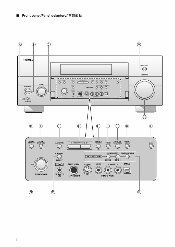
Front panel/Panel delantero/ 前部面板
MASTER
PURE DIRECT
VOLUME
MAIN ZONE
INPUT
OFFON
SLEEP
ZONE ON/OFF ZONE CONTROLS
MULTI ZONE
MICOPTIMIZER
EFFECT
PROGRAM
YPAO
ZONE 3
RL OPTICAL
ZONE 2
AUDIO
VIDEO AUX
SILENT CINEMA S VIDEO VIDEO
PHONES
MODETUNING
EDIT
FM/AMTUNINGPRESET/
MAN'L/AUTO FMMEMORY
STRAIGHT
CONTROLSELECTAUDIO TONE
A/B/C/D/E PRESET/TUNING
ON/OFF
SLEEP
ZONE ON/OFF ZONE CONTROLS
MULTI ZONE
MICOPTIMIZER
EFFECT
PROGRAM
YPAO
ZONE 3
RL OPTICAL
ZONE 2
AUDIO
VIDEO AUX
SILENT CINEMA S VIDEO VIDEO
PHONES
MODETUNING
PRESET/TUNING
EDIT
FM/AMTUNINGPRESET/
MAN'L/AUTO FMMEMORY
STRAIGHT
CONTROLSELECTAUDIO TONE
A/B/C/D/E
CB M
LK
Q
PN
IGF
O
ED
A
H J
i

AP
PE
ND
IX
Remote control/Mando a distancia/ 遥控器
–
+ +
––
+
ENTER
DISPLAY
AUDIO
MENUTITLE
TV MUTE TV INPUT MUTE
432
ENT+1009
5
1
AVTV
76 8
432
09
5
1
76 8
RETURN
ONOFF CLEARLEARN RENAMEMACRO
REC
DISC SKIP
VOLUMECHTV VOL
EFFECT
PARAMETER STRAIGHTA/B/C/D/E
SRCH MODE
PURE DIRECTPRESET/CH
SET MENU
BAND
LEVEL
CLASSICAL LIVE/CLUB ENTERTAIN MOVIE
SYSTEM MEMORY
SUR. DECODE
FREQ/TEXT EON MODE – PTY SEEK – START
ENHANCERSTEREO
TV
SOURCE
AMP
SELECT
DTV/CBL VCRDVR V-AUX/DOCK
TUNER CD CD-R MULTI CH IN
POWER POWER POWERSTANDBY
SLEEPAUDIO SEL
CLASSICAL LIVE/CLUB ENTERTAIN MOVIE
SYSTEM MEMORY
ENHANCERSTEREO
DVD BD/HD DVD PHONOMD/TAPE1
2
3
4
M
PO
5
6
7
8
0
B
A
9
C
FE
D
G
H
L
I
JK
N
ii

Sound output in each sound field programSalida de sonido en cada programa de campo acústic各声场程序的声音输出
Front left speaker Surround left speaker Surround back right speaker
Center speaker Surround right speaker Presence left speaker
Front right speaker Surround back left speaker Presence right speaker
Speaker from which sound is being output Speaker from which no sound is being output
L SL SBR
C SR PL
R SBL PR
Speaker settings
7-channel 5-channel
1
2
3
4
L
PL
C
R
PR
SL
SBRSBL
SR
L
C
R
SL SR
L
PL
C
R
PR
SL
SBRSBL
SR
L
C
R
SL SR
L
PL
C
R
PR
SL
SBRSBL
SR
L
C
R
SL SR
L
PL
C
R
PR
SL
SBRSBL
SR
L
C
R
SL SR
Speaker settings
7-channel 5-channel
5
6
7
8
L
PL
C
R
PR
SL
SBRSBL
SR
L
C
R
SL SR
L
PL
C
R
PR
SL
SBRSBL
SR
L
C
R
SL SR
L
PL
C
R
PR
SL
SBRSBL
SR
L
C
R
SL SR
L
PL
C
R
PR
SL
SBRSBL
SR
L
C
R
SL SR
iii

AP
PE
ND
IX
*1 / / : OFF
*2 / / : ON or discrete 6.1/7.1-channel audio signals are input.
EX PL x
EX PL x
Program PRIORITY
Input audio source
2-channel (monaural)
2-channel (stereo) 5.1-channel*1 6.1/7.1-channel*2
CLASSICALHall in MunichHall in ViennaHall in AmsterdamChurch in FreiburgChamber
LIVE/CLUBVillage VanguardWarehouse LoftCellar ClubThe Roxy TheatreThe Bottom Line
PRNS 1 1 2 4
SB
1 1 2 4
ENTERTAINMENTSportsMusic VideoRecital/OperaAction GameRoleplaying Game
MOVIESTANDARDSpectacleSci-FiAdventureDrama
PRNS 3 2 2 4
SB
7 4 2 4
MOVIEMono Movie
PRNS 3 2 2 4
SB 3 2 2 4
STEREO2ch Stereo
PRNS/SB 5 5 5 5
STEREO7ch Stereo
MUSIC ENHANCER7ch Enhancer
PRNS/SB
4 4 4 4
SUR.DECODESur. Decode
(Pro Logic)(PLII Movie)(PLII Game)
PRNS/SB
6 7 7 4
SUR.DECODESur. Decode
(PLII Music)
PRNS/SB8 7 7 4
SUR.DECODESur. Decode
(PLIIx Movie)(PLIIx Game)(Neo:6 Cinema)
PRNS/SB
6 4 7 4
SUR.DECODESur. Decode
(PLIIx Music)(Neo:6 Music)
PRNS/SB
8 4 7 4
STRAIGHTPure DirectMUSIC ENHANCERStraight Enhancer
PRNS/SB
5 5 7 4
iv
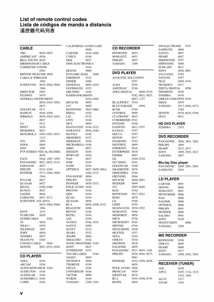
List of remote control codesLista de códigos de mando a distancia遥控器代码列表
CABLEABC 0030, 0035AMERICAST 0926BELL SOUTH 0926BIRMINGHAM CABLE COMMUNICATIONS
0303BRITISH TELECOM 0030CABLE & WIRELESS
1095DAERYUNG 0035, 0504, 0904,
1904DIRECTOR 0503FILMNET 0470GENERAL INSTRUMENT
0030, 0303, 0503, 0837,
GOLDSTAR 0171HAMLIN 0036, 0300JERROLD 0030, 0303, 0503,
0837LG 0171MNET 0470MEMOREX 0027MOTOROLA 0303, 0503, 0837,
1133NTL 1095NOOS 0844ONO 1095PVP STEREO VISUAL MATRIX
0030PACE 0264, 1087, 1095PANASONIC 0027, 0035, 0134PARAGON 0027PHILIPS 0332, 0344PIONEER 0171, 0560, 0904,
1904PULSAR 0027QUASAR 0027REGAL 0300, 0306RUNCO 0027SAGEM 0844SAMSUNG 0027, 0171SCIENTIFIC ATLANTA
0035, 0504, 0904, 1904
SONY 1033STARCOM 0030SUPERCABLE 0303TS 0030TELE+1 0470TELEWEST 1095TORX 0030TOSHIBA 0027TRANS PX 0303UNITED CABLE 0030ZENITH 0027, 0552, 0926
CD PLAYER AIWA 0184ARCAM 0184AUDIO RESEARCH 0184AUDIO TON 0184AUDIOLAB 0184AUDIOMECA 0184CAIRN 0184
CALIFORNIA AUDIO LABS0056
CARVER 0184, 0206CYRUS 0184DKK 0027DMX ELECTRONICS
0184DENON 0900DYNAMIC BASS 0206EMERSON 0332FISHER 0206GENEXXA 0059, 0332GOODMANS 0332GRUNDIG 0184HARMAN/KARDON
0184, 0200HITACHI 0059JVC 0099KENWOOD 0055, 0064KRELL 0184LXI 0332LINN 0184MCS 0056MAGNAVOX 0184, 0332MARANTZ 0056, 0184MATSUI 0184MEMOREX 0332MERIDIAN 0184MICROMEGA 0184MIRO 0027MISSION 0184MYRYAD 0184NAD 0027NSM 0184NAIM 0184OPTIMUS 0027, 0059, 0064,
0206, 0332PANASONIC 0056PHILIPS 0184PIONEER 0059, 0332POLK AUDIO 0184PROTON 0184QED 0184QUAD 0184QUASAR 0056RCA 0059, 0206, 0332REALISTIC 0206REVOX 0184ROTEL 0184SAE 0184SANSUI 0184, 0332SANYO 0206SCOTT 0332SEARS 0332SHARP 0064SIMAUDIO 0184SONIC FRONTIERS 0184SONY 0027SYMPHONIC 0332TAG MCLAREN 0184TANDY 0059TECHNICS 0056THORENS 0184THULE 0184UNIVERSUM 0184VICTOR 0099WARDS 0184YAMAHA 2300, 2301
CD RECORDER KENWOOD 0653MARANTZ 0653PHILIPS 0653YAMAHA 2400
DVD PLAYER ACOUSTIC SOLUTIONS
0757ALBA 0744AMSTRAD 0740APEX DIGITAL 0699, 0744,
0782, 0821, 0823, 0857, 1127
BLAUPINKT 0744BLUE PARADE 0598BUSH 0740CENTREX 0699CLATRONIC 0815CYBERHOME 0741DVD2000 0548DAEWOO 0811, 0797DANSAI 0797DECCA 0797DENON 0517DIAMOND 0795DIGITREX 0699EMERSON 0618ENTERPRISE 0618FISHER 0697GE 0549, 0744GO VIDEO 0742GOLDSTAR 0768GRADIENTE 0678GREENHILL 0744GRUNDIG 0566HITACHI 0600, 0691HITEKER 0699JVC 0585, 0650KLH 0744KENWOOD 0517, 0561KOSS 0678LG 0768LIMIT 0795MAGNAVOX 0530, 0702MARANTZ 0566MEMOREX 0858MICO 0750MICROSOFT 0549MINTEK 0744MITSUBISHI 0548MUSTEK 0757NESA 0744ONKYO 0530ORITRON 0678PALSONIC 0699PANASONIC 0517, 0659, 1389PHILIPS 0530, 0566, 0673,
0881PIONEER 0552, 0598, 0658,
0659POLK AUDIO 0566PROSCAN 0549QWESTAR 0678RCA 0549, 0598, 0744ROTEL 0650
SM ELECTRONIC 0757SAMSUNG 0600SANYO 0697SHARP 0657SHERWOOD 0797SHINSONIC 0560SLIM ART 0811SONY 0560, 0891SYLVANIA 0702TATUNG 0797TEAC 0598, 0744TECHNICS 0517THETA DIGITAL 0598THOMSON 0549TOSHIBA 0530URBAN CONCEPTS 0530XBOX 0549YAMAHA 0517, 0566, 0572,
2100ZENITH 0530, 0618, 0768ZEUS 0811
HD DVD PLAYERTOSHIBA 2103
DVD RECORDERPANASONIC 2800, 2801, 2802PHILIPS 2808SHARP 2812, 2813SONY 2809, 2810, 2811YAMAHA 2807
Blu-lay Disc playerPANASONIC 2800, 2801, 2802SAMSUNG 2816
LD PLAYER CARVER 0091DENON 0086MARANTZ 0091MITSUBISHI 0086NAD 0086NAGSMI 0086OPTIMUS 0086PHILIPS 0091PIONEER 0086SALORA 0091SONY 0228TELEFUNKEN 0086YAMAHA 2200
MD RECORDERKENWOOD 0708ONKYO 0895SHARP 0888SONY 0517YAMAHA 2500, 2501, 2502
RECEIVER (TUNER)ADC 0558AIWA 0185, 1116, 1415,
1432, 1668ALCO 1417ANAM 1636
v

AP
PE
ND
IX
APEX DIGITAL 1284AUDIOLAB 1216AUDIOTRONIC 1216AUDIOVOX 1417BOSE 1256CAMBRIDGE SOUNDWORKS
1397CAPETRONIC 0558CARVER 1116, 1216CENTREX 1284DENON 1387FERGUSON 0558FINE ARTS 1216GRUNDIG 1216HARMAN/KARDON
0137, 1331INTEGRA 0162, 1325JBL 0137, 1333JVC 0101, 0558, 1401,
1522KLH 1417, 1439KENWOOD 1054, 1340MCS 0066MAGNAVOX 0558, 1116, 1216,
1296, MARANTZ 0066, 1116, 1216,
1316MICROMEGA 1216MUSICMAGIC 1116MYRYAD 1216NAD 0347NORCENT 1416ONKYO 0162, 0869, 1325OPTIMUS 0558, 1050PANASONIC 0066, 1315, 1545,
1790PHILIPS 1116, 1216, 1293,
1295, 1296, 1310, 1316
PIONEER 0041, 0558, 1050, 1411
POLK AUDIO 1316PROSCAN 1281QUASAR 0066RCA 0558, 1050, 1281,
1417, 1636, SABA 0558SANSUI 1116SCHNEIDER 0558SONY 0185, 1085, 1185,
1685, 1785STEREOPHONICS 1050SUNFIRE 1340TEAC 1417TECHNICS 0066, 1335, 1336,
1545TELEFUNKEN 0558THOMSON 1281THORENS 1216UHER 0558VENTURER 1417VICTOR 0101WARDS 0041, 0185YAMAHA 0203, 1203, 1358,
2601(TUNER ID1) 2602(TUNER ID2) 2603(iPod) 2606
SATELLITE TUNER@SAT 1327ABSAT 0150ALBA 0482ALPHASTAR 0799
AMSTRAD 0874ASTON 0169, 1156ASTRO 0200ATSAT 1327AVALON 0423BLAUPUNKT 0200BRITISH SKY BROADCASTING
0874, 1202CANAL DIGITAL 0880CANAL SATELLITE 0880CANAL+ 0880CHAPARRAL 0243CITYCOM 1203CONNEXIONS 0423CROSSDIGITAL 1136CYRUS 0227D-BOX 0750, 1154DMT 1102DNT 0227, 0423DAERYUNG 0423DAEWOO 1323DIGENIUS 0326DIRECTV 0274, 0419, 0593,
0666, 0751, 0776, 0846, 1103, 1136, 1169, 1776, 1883
DISH NETWORK SYSTEM0802, 1032
DISHPRO 0802, 1032DISTRATEL 0111DREAM MULTIMEDIA
1264ECHOSTAR 0194, 0423, 0637,
0802, 0880, 0898, 1032, 1113
ENGEL 1044EXPRESSVU 0802FTE 0890FINLUX 0482FRACARRO 0898FUBA 0423GE 0593GOI 0802GALAXIS 0890, 1138GENERAL INSTRUMENT
0896GOLD BOX 0880GRUNDIG 0200, 0874HTS 0802HIRSCHMANN 0200, 0423HITACHI 0482, 0846HUGHES NETWORK SYSTEM
0776, 1169, 1776HUMAX 0890, 1203INVIDEO 0898JVC 0802KATHREIN 0150, 0200, 0227,
0276, 0685, 1248KREISELMEYER 0200LABGEAR 1323LOGIX 1044LORENZEN 0326MAGNAVOX 0749, 0751MANHATTAN 0482, 1044,
1110MARANTZ 0227MEDIASAT 0880MEMOREX 0751METRONIC 0111MITSUBISHI 0776MOTOROLA 0896MYRYAD 0227NEXT LEVEL 0896
NOKIA 0482, 0750, 0778, 1154, 1250, 1750
OCTALTV 1032ORBITECH 1127PACE 0482, 0874, 1202,
1350PANASONIC 0274, 0728, 0874,
1347PANDA 0482PAYSAT 0751PHILIPS 0160, 0227, 0482,
0749, 0751, 0776, 0880, 1103, 1169, 1776
PIONEER 0880PROMAX 0482PROSCAN 0419, 0593RCA 0170, 0419, 0593,
0882RFT 0227RADIOSHACK 0896RADIOLA 0227RADIX 0423SKY 0874, 0883, 1202SM ELECTRONIC 1227SABRE 0482SAGEM 0847, 1141, 1280SAMSUNG 1044, 1136, 1303,
1319SAT CONTROL 1327SATSTATION 1110SCHWAIGER 1138SEEMANN 0423SIEMENS 0200SONY 0666, 0874, 1666STAR CHOICE 0896STRONG 1327TPS 0847, 1280TANTEC 0482TECHNISAT 1126, 1127TELESTAR 1127THOMSON 0482, 0880, 1073,
1318TOPFIELD 1233TOSHIBA 0776, 0817, 1776ULTIMATETV 0419, 0666UNIDEN 0749, 0751UNIVERSUM 0200VENTANA 0227WISI 0200, 0423, 0482XSAT 0150ZEHNDER 1102ZENITH 0883, 1883
TAPE DECK AIWA 0056CARVER 0056GRUNDIG 0056HARMAN/KARDON
0056MAGNAVOX 0056MARANTZ 0056MYRYAD 0056OPTIMUS 0054PHILIPS 0056PIONEER 0054POLK AUDIO 0056RCA 0054REVOX 0056SANSUI 0056SONY 0270THORENS 0056WARDS 0054YAMAHA 2700,2701
TVAGB 0543AOC 0036, 0057, 0087,
0119, 0120, 0135, 0205, 0207, 0478
ASA 0131AWA 0036ACURA 0036ADDISON 0119, 0135, 0680ADMIRAL 0120, 0190, 0490ADVENT 0788AIKO 0119AKAI 0036, 0057, 0235,
0388, 0543, 0729, 0839
AKURA 0291ALBA 0036, 0064, 0398,
0695AMERICA ACTION 0207AMPRO 0778AMSTRAD 0036, 0064, 0198,
0398, 0439, 0460, 0543
ANAM 0036, 0207, 0277ANAM NATIONAL 0277, 0677ANITECH 0036APEX DIGITAL 0775, 0792,
0794AUDIOSONIC 0064, 0136BANG & OLUFSEN 0592BASIC 0036BAUR 0064, 0388, 0539BAYSONIC 0207BEAUMARK 0205BEKO 0397, 0513, 0741,
0742BELL & HOWELL 0181BEON 0064BLAUPUNKT 0222BLUE SKY 0695, 1064BONDSTEC 0274BRADFORD 0207BRANDT 0136, 0362BROKSONIC 0263, 0490BUSH 0036, 0064, 0398,
0401, 0695, 1064CCE 0064CGE 0274CTC 0274CXC 0207CANDLE 0057CARNIVALE 0057CARVER 0081, 0197CASCADE 0036CATHAY 0064CELEBRITY 0027CELERA 0792CENTURION 0064CHANGHONG 0792CHING TAI 0036, 0119CHUN YUN 0027, 0036, 0119,
0207CHUNG HSIN 0080, 0135, 0207CIMLINE 0036CINERAL 0119, 0478CITIZEN 0057, 0087, 0119CLARION 0207CLARIVOX 0064CLATRONIC 0274, 0397CONDOR 0347, 0397CONRAC 0835CONTEC 0036, 0207CRAIG 0207CROSLEY 0081
vi

CROWN 0036, 0064, 0207, 0397, 0445
CURTIS MATHES 0057, 0074, 0081, 0087, 0120, 0172, 0181, 0193, 0478, 0729, 1174, 1374
DAEWOO 0036, 0057, 0064, 0119, 0135, 0181, 0197, 0205, 0207, 0401, 0478, 0650, 0661, 1688
DANSAI 0064DAYTON 0036DE GRAAF 0235, 0575DECCA 0064, 0543DENON 0172DIGATRON 0064DIXI 0036, 0064DUMONT 0044DWIN 0747, 0801ECE 0064ELBE 0286ELECTROBAND 0027ELIN 0064, 0575ELITE 0347ELTA 0036EMERSON 0181, 0205, 0207,
0263, 0388, 0490, 0650
ENVISION 0057,0840EPSON 0860ERRES 0064ETHER 0036, 0057ETRON 0036EUROPHON 0543FERGUSON 0064, 0100, 0136,
0265, 0314, 0362, 0587
FIDELITY 0388FINLANDIA 0235, 0373FINLUX 0064, 0131, 0132,
0373, 0543FIRSTAR 0036, 0263FIRSTLINE 0036, 0274, 0695FISHER 0131, 0181, 0235,
0397FLINT 0482FORMENTI 0064, 0347FORTRESS 0120FRONTECH 0190, 0274, 0291FUJITSU 0710, 0836FUNAI 0207, 0198, 0291FUTURETECH 0207GE 0057, 0074, 0078,
0119, 0205, 0207, 0478, 0587, 1174, 1374, 1481
GEC 0064, 0543GATEWAY 1782, 1783GELOSO 0036GENEXXA 0190GIBRALTER 0044, 0057GOLDSTAR 0057, 0064, 0136,
0181, 0205, 0404GOODMANS 0064, 0398, 0401,
0661GOREMJE 0397GRADIENTE 0080, 0197GRAETZ 0190, 0388GRANADA 0064, 0235, 0366,
0543GRANDIN 0637GRUNDIG 0064, 0222, 0514,
0583, 0614
GRUNPY 0207HCM 0036, 0439HALLMARK 0205HANKOOK 0057, 0205, 0207HANSEATIC 0064, 0347, 0388,
0455, 0583HANTAREX 0543HARMAN/KARDON 0081HARVARD 0207HAVERMY 0120HELLO KITTY 0478HINARI 0036, 0064HISAWA 0482HITACHI 0036, 0057, 0119,
0132, 0136, 0172, 0190, 0205, 0252, 0383, 0508, 0575, 0605, 1172, 1283
HUA TUN 0036HUANYU 0401HYPSON 0064, 0291ICE 0291, 0398ITS 0398ITT 0190, 0388, 0575IMPERIAL 0274, 0397, 0445INDIANA 0064INFINITY 0081INGELEN 0190INNO HIT 0543INNOVA 0064INTEQ 0044INTERFUNK 0064, 0190, 0274,
0388, 0539INTERVISION 0064, 0291,
0404JBL 0081JCB 0027JVC 0080, 0398, 0490,
0680, 0710JEAN 0036, 0078, 0119,
0183, 0263JENSEN 0788KEC 0207KTV 0057, 0207KAISUI 0036KAPSCH 0190KARCHER 0637KATHREIN 0583KENDO 0064KENWOOD 0057KNEISSEL 0286, 0462KOLIN 0080, 0135, 0207KORPEL 0064KOYODA 0036L&S ELECTRONIC 0835LG 0057, 0064, 0087,
0135, 0205, 0741LXI 0074, 0081, 0181,
0183, 0205LEYCO 0064, 0291LIESENK & TTER 0064LOEWE 0539LUXOR 0383, 0388M ELECTRONIC 0036, 0064,
0131, 0132, 0136, 0190, 0314, 0373, 0401, 0507
MGA 0057, 0177, 0205MTC 0057, 0087, 0539MAGNADYNE 0274, 0543MAGNAFON 0543MAGNAVOX 0057, 0081, 1281,
1481MANESTH 0291, 0347
MARANTZ 0057, 0064, 0081, 0583
MARK 0064MATSUI 0036, 0064, 0235,
0398, 0514, 0543MATSUSHITA 0277, 0677MEDIATOR 0064MEDION 0695, 0835, 1064MEGATRON 0172, 0205MEMOREX 0036, 0177, 0181,
0205, 0277, 0490, 1064
METZ 0474MICROMAXX 0835MICROSTAR 0835MIDLAND 0044, 0074, 0078MINERVA 0514MINOKA 0439MITSUBISHI 0057, 0120, 0135,
0177, 0181, 0205, 0207, 0263, 0277, 0539, 0863, 1277
MIVAR 0318,0319, 0543, 0636
MOTOROLA 0120MULTITECH 0036, 0207MYRYAD 0583NAD 0183, 0205, 0388,
0893NEC 0036, 0057, 0078,
0181, 0183, 0197, 0205, 0482, 0524, 1731
NEI 0064NTC 0119NECKERMANN 0064, 0583NETSAT 0064NEWAVE 0036, 0119, 0120,
0205NIKKAI 0064, 0291NIKKO 0057, 0119, 0205NOKIA 0388, 0500, 0507,
0575, 0658NORCENT 0775, 0851NORDMENDE 0136, 0314,
0587OCEANIC 0190, 0388ONWA 0207, 0460OPTIMUS 0181, 0193, 0277,
0677OPTONICA 0120ORION 0064, 0263, 0347,
0490, 0543OSAKI 0291, 0439OTTO VERSAND 0064, 0347,
0539, 0583PALLADIUM 0397, 0445PANAMA 0291PANASONIC 0064, 0078, 0081,
0190, 0277, 0677, 1437
PATHE CINEMA 0265, 0347PAUSA 0036PENNEY 0057, 0074, 0078,
0087, 0183, 0205, 1374
PERDIO 0347PHILCO 0057, 0064, 0081,
0172, 0205, 0207, 0274, 0490, 1688
PHILIPS 0027, 0057, 0064, 0078, 0081, 0119, 0135, 0205, 0401, 0583, 0717, 1481
PHONOLA 0064
PILOT 0057PIONEER 0136, 0190, 0193,
0314, 0706, 0787, 0893
PORTLAND 0119PRANDONI-PRINCE
0543PRIMA 0788PRISM 0078PROFEX 0036, 0388PROSCAN 0074PROTECH 0036, 0064, 0274,
0291, 0445, 0695PROTON 0036, 0057, 0205PULSAR 0044QUASAR 0078, 0277, 0677QUELLE 0064, 0131, 0388,
0539R-LINE 0064RCA 0027, 0057, 0074,
0117, 0119, 0205, 0706, 1074, 1174, 1274, 1374, 1474, 1481, 1574
RFT 0455RADIOSHACK 0057, 0074,
0181, 0205, 0207RADIOLA 0064RADIOMARELLI 0543REALISTIC 0057, 0181, 0205,
0207REDIFFUSION 0388REOC 0741REVOX 0064REX 0190, 0286, 0291ROADSTAR 0036, 0291, 0445RUNCO 0044, 0057, 0524,
0630SBR 0064SEG 0291, 0695SEI 0543SKY 0064SSS 0207SABA 0136, 0190, 0314,
0362SACCS 0265SAGEM 0637SAISHO 0036, 0291, 0543SALORA 0190, 0380, 0388,
0575SAMBERS 0543SAMPO 0036, 0057, 0119,
0120, 0181, 0198, 0205, 0677, 1782
SAMSUNG 0036, 0057, 0064, 0087, 0117, 0119, 0181, 0205, 0291, 0397, 0583, 0614, 0645, 0729, 0793, 0839, 0841
SANSEI 0478SANSUI 0490SANYO 0131, 0181, 0207,
0235, 0366, 0826SCHAUB LORENZ 0388SCHNEIDER 0064, 0274, 0398,
0695SCOTCH 0205SCOTT 0205, 0207, 0263SEARS 0074, 0081, 0181,
0183, 0198, 0205SELECO 0190, 0286SEMIVOX 0207SEMP 0183SHARP 0057, 0120, 0677
vii

AP
PE
ND
IX
SHEN YING 0036, 0119SHENG CHIA 0036, 0120, 0263SIAREM 0543SIEMENS 0064, 0222SINUDYNE 0543SKANTIC 0383SKYGIANT 0207SKYWORTH 0064SOLAVOX 0190SONITRON 0235SONOKO 0036, 0064SONOLOR 0190, 0235SONTEC 0064SONY 0027, 0677, 0861,
1127, 1532, 1678SOUNDESIGN 0205, 0207SOUNDWAVE 0064, 0445SOWA 0078, 0087, 0119,
0183, 0205SQUAREVIEW 0198STANDARD 0036STARLITE 0207STERN 0190, 0286SUPREME 0027SYLVANIA 0057, 0081, 0198SYMPHONIC 0198, 0207SYNCO 0027, 0087, 0119,
0120, 0205, 0478SYSLINE 0064T + A 0474TCM 0835TMK 0205TNCI 0044TVS 0490TACICO 0036, 0119, 0205TAI YI 0036TANDY 0120, 0190TASHIKO 0119, 0677TATUNG 0036, 0064, 0078,
0081, 0087, 0181, 0183, 0543
TEAC 0036, 0064, 0291, 0439, 0445, 0482, 0695, 1064
TEC 0274TECHNEMA 0347TECHNICS 0078, 0277, 0677TECHWOOD 0078TECO 0036, 0078, 0119,
0120, 0205, 0291, 0680
TEKNIKA 0081, 0087, 0119, 0177, 0207
TELEFUNKEN 0136, 0289, 0362, 0652, 0729
TELEMEISTER 0347TELETECH 0036TENSAI 0347TERA 0057THOMSON 0136, 0314, 0587,
0652, 1474THORN 0064, 0131, 0388,
0539TOSHIBA 0087, 0181, 0183,
0535, 0645, 0677, 0859, 1283, 1383, 1683, 1731
TRIUMPH 0543TUNTEX 0036, 0057, 0119UHER 0347UNIVERSUM 0064, 0131, 0132,
0291, 0373, 0397, 0519
VECTOR RESEARCH0057
VESTEL 0064VICTOR 0080, 0277, 0677,
0680VIDEOSAT 0274VIDIKRON 0081VIDTECH 0205VIEWSONIC 1782VISION 0347VOXSON 0190WALTHAM 0383WARDS 0057, 0081, 0205,
0893WATSON 0064, 0347WAYCON 0183WHITE WESTINGHOUSE
0064, 0347, 0490, 0650
YAMAHA 0057, 0172, 0677, 0796, 0860, 2900 (projector), 2901 (projector), 2903, 2904 (projector)
YAPSHE 0277YOKO 0064, 0291ZENITH 0044, 0119, 0205,
0490
VCR ASA 0064, 0108ADMIRAL 0075ADVENTURA 0027AIKO 0305AIWA 0027, 0064, 0334,
0375, 0379AKAI 0068, 0342AKIBA 0099ALBA 0099, 0305, 0342,
0379AMERICA ACTION 0305AMERICAN HIGH 0062AMSTRAD 0027ANAM 0064, 0253, 0267,
0305, 0507ANAM NATIONAL 0253, 1589ANITECH 0099ASHA 0267ASUKA 0064AUDIOVOX 0064, 0305BAIRD 0027, 0068, 0131BASIC LINE 0099, 0305BEAUMARK 0267BELL & HOWELL 0131BLAUPUNKT 0253BRANDT 0347BRANDT ELECTRONIC
0068BROKSONIC 0211, 0375, 1506BUSH 0099, 0305, 0379CCE 0099, 0305CGE 0027CALIX 0064CANON 0062CARVER 0108CIMLINE 0099CINERAL 0305CITIZEN 0064, 0305, 1305COLT 0099COMBITECH 0379CRAIG 0064, 0074, 0099,
0267CROWN 0099, 0305CURTIS MATHES 0062, 0068,
0087, 1062
CYBERNEX 0267CYRUS 0108DAEWOO 0072, 0131, 0305,
0669, 1305DANSAI 0099DE GRAAF 0069DECCA 0027, 0108DENON 0069DUAL 0068DUMONT 0027, 0108, 0131DYNATECH 0027ESC 0267, 0305ELCATECH 0099ELECTROHOME 0064ELECTROPHONIC 0064EMEREX 0059EMERSON 0027, 0062, 0064,
0070, 0072, 0211, 0267, 0305, 1305, 1506
FERGUSON 0068, 0347FIDELITY 0027FINLANDIA 0108, 0131FINLUX 0027, 0069, 0108,
0131FIRSTLINE 0064, 0070, 0072,
0099FISHER 0074, 0131FUJI 0060, 0062FUJITSU 0027, 0072FUNAI 0027GE 0062, 0087, 0267,
0834, 1062, 1087GEC 0108GARRARD 0027GENERAL 0072GO VIDEO 0459GOLDHAND 0099GOLDSTAR 0064, 0252, 0507,
1264GOODMANS 0027, 0064, 0099,
0305GRADIENTE 0027GRAETZ 0068, 0131, 0267GRANADA 0108, 0131GRANDIN 0027, 0064, 0099GRUNDIG 0099, 0108, 0253,
0374HCM 0099HI-Q 0074HANSEATIC 0064HARLEY DAVIDSON
0027HARMAN/KARDON 0108HARWOOD 0099HINARI 0099, 0267, 0379HITACHI 0027, 0064, 0068,
0069, 0267HUGHES NETWORK SYSTEMS
0069HYPSON 0099ITT 0068, 0131, 0267ITV 0064, 0305IMPERIAL 0027INTERFUNK 0108JVC 0068, 0072, 0094JENSEN 0068KEC 0064, 0305KLH 0099KAISUI 0099KENWOOD 0068, 0094KODAK 0062, 0064KOLIN 0068, 0070KORPEL 0099
LG 0064, 0069, 0072, 0507
LXI 0064LENCO 0305LEYCO 0099LLOYD’S 0027LOEWE 0064, 0108, 1589LOGIK 0099, 0267LUXOR 0070, 0075, 0131M ELECTRONIC 0027MEI 0062MGA 0070, 0267MGN TECHNOLOGY
0267MTC 0027, 0267MAGNASONIC 1305MAGNAVOX 0027, 0062, 0066,
0108, 1808MAGNIN 0267MANESTH 0072, 0099MARANTZ 0062, 0108MARTA 0064MATSUI 0375, 0379MATSUSHITA 0062MEDION 0375MEMOREX 0027, 0062, 0064,
0066, 0074, 0075, 0131, 0267, 0334, 0375, 1264
MEMPHIS 0099METZ 0064, 0374, 1589MINOLTA 0069MITSUBISHI 0068, 0070, 0094,
0108, 0834MOTOROLA 0062, 0075MULTITECH 0027, 0099MURPHY 0027MYRYAD 0108NAD 0131NEC 0062, 0064, 0068,
0075, 0094, 0131NATIONAL 0253NECKERMANN 0108NESCO 0099NEWAVE 0064NIKKO 0064NOBLEX 0267NOKIA 0068, 0131, 0267NORDMENDE 0068, 0347OCEANIC 0027, 0068OKANO 0342, 0375OLYMPUS 0062, 0253OPTIMUS 0064, 0075, 0131,
0459ORION 0211, 0375, 0379,
1506OSAKI 0027, 0064, 0099OTTO VERSAND 0108PALLADIUM 0064, 0068, 0099PANASONIC 0062, 0252, 0253,
0643, 1062, 1589PATHE MARCONI 0068PENNEY 0062, 0064, 0069,
0267, 1062, 1264PENTAX 0069PERDIO 0027PHILCO 0062PHILIPS 0062, 0108, 0645,
1108, 1208PHONOLA 0108PILOT 0064PIONEER 0069, 0094, 0108POLK AUDIO 0108PROFITRONIC 0267PROLINE 0027
viii
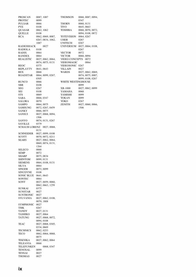
PROSCAN 0087, 1087PROTEC 0099PULSAR 0066PYE 0108QUASAR 0062, 1062QUELLE 0108RCA 0062, 0069, 0087,
0267, 0834, 1062, 1087
RADIOSHACK 0027RADIOLA 0108RADIX 0064RANDEX 0064REALISTIC 0027, 0062, 0064,
0074, 0075, 0131REOC 0375REPLAYTV 0641, 0643REX 0068ROADSTAR 0064, 0099, 0267,
0305RUNCO 0066SBR 0108SEG 0267SEI 0108STS 0069SABA 0068, 0347SALORA 0070SAMPO 0064, 0075SAMSUNG 0072, 0267, 0459SANKY 0066, 0075SANSUI 0027, 0068, 0094,
1506SANYO 0074, 0131, 0267SAVILLE 0379SCHAUB LORENZ 0027, 0068,
0131SCHNEIDER 0027, 0099, 0108SCOTT 0070, 0072, 0211SEARS 0027, 0062, 0064,
0069, 0074, 0131, 1264
SELECO 0068SEMP 0072SHARP 0075, 0834SHINTOM 0099, 0131SIEMENS 0064, 0108, 0131SILVA 0064SINGER 0072, 0099SINUDYNE 0108SONIC BLUE 0641, 0643SONTEC 0064SONY 0027, 0059, 0060,
0062, 0663, 1259SUNKAI 0375SUNSTAR 0027SUNTRONIC 0027SYLVANIA 0027, 0062, 0108,
0070, 1808SYMPHONIC 0027TMK 0267TANDY 0027, 0131TASHIKO 0027, 0064TATUNG 0027, 0068, 0072,
0094, 0108TEAC 0027, 0068, 0305,
0334, 0669TECHNICS 0062, 0253TECO 0062, 0064, 0068,
0075TEKNIKA 0027, 0062, 0064TELEAVIA 0068TELEFUNKEN 0068, 0347TENOSAL 0099TENSAI 0027THOMAS 0027
THOMSON 0068, 0087, 0094, 0347
THORN 0068, 0131TIVO 0645, 0663TOSHIBA 0068, 0070, 0072,
0094, 0108, 0872TOTEVISION 0064, 0267UHER 0267UNITECH 0267UNIVERSUM 0027, 0064, 0108,
0267VECTOR 0072VICTOR 0068, 0094VIDEO CONCEPTS 0072VIDEOMAGIC 0064VIDEOSONIC 0267VILLAIN 0027WARDS 0027, 0062, 0069,
0074, 0075, 0087, 0099, 0108, 0267
WHITE WESTINGHOUSE0099
XR-1000 0027, 0062, 0099YAMAHA 0068YAMISHI 0099YOKAN 0099YOKO 0267ZENITH 0027, 0060, 0066,
1506
ix
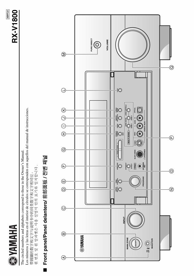
The
cir
cled
num
bers
and
alp
habe
ts c
orre
spon
d to
thos
e in
the
Ow
ner’
s M
anua
l.L
os n
úmer
os y
las
letr
as e
n el
inte
rior
de
círc
ulos
se
corr
espo
nden
con
aqu
ello
s de
l man
ual d
e in
stru
ccio
nes.
带圆圈的数字和文字与说明书中的同类数字和文字相对应。
원 번
호 및
원 알
파벳
은 사
용 설
명서
안의
표기
와 일
치합
니다
.
F
ron
t p
anel
/Pan
el d
elan
tero
/前部面板
/전변
패널
RX
-V18
00AB
RT
LK
MA
ST
ER
PU
RE
DIR
EC
T
VO
LU
ME
MA
IN Z
ON
E
INP
UT
OFFON
SL
EE
P
ZO
NE
ON
/OF
FZO
NE
CO
NTR
OLS
MU
LT
I Z
ON
E
MIC
OP
TIM
IZE
R
EF
FE
CT
PR
OG
RA
M
YPA
O
ZO
NE
3
RL
OP
TIC
AL
ZO
NE
2 AU
DIO
VID
EO
AU
X
SIL
EN
T C
INE
MA
S V
IDE
OV
IDE
O
PH
ON
ES
MO
DE
TU
NIN
G
ED
IT
FM
/AM
TU
NIN
GP
RE
SE
T/
MAN
'L/A
UTO
FM
ME
MO
RY
ST
RA
IGH
T
CO
NT
RO
LS
EL
EC
TA
UD
IOTO
NE
A/B
/C/D
/EP
RE
SE
T/T
UN
ING
ON
/OF
F
CB
M
Q
AL
K
PN
IG
F
O
ED
HJ
00_sheet_RX-V1800_ABRTLK.book Page 1 Friday, June 15, 2007 10:39 PM
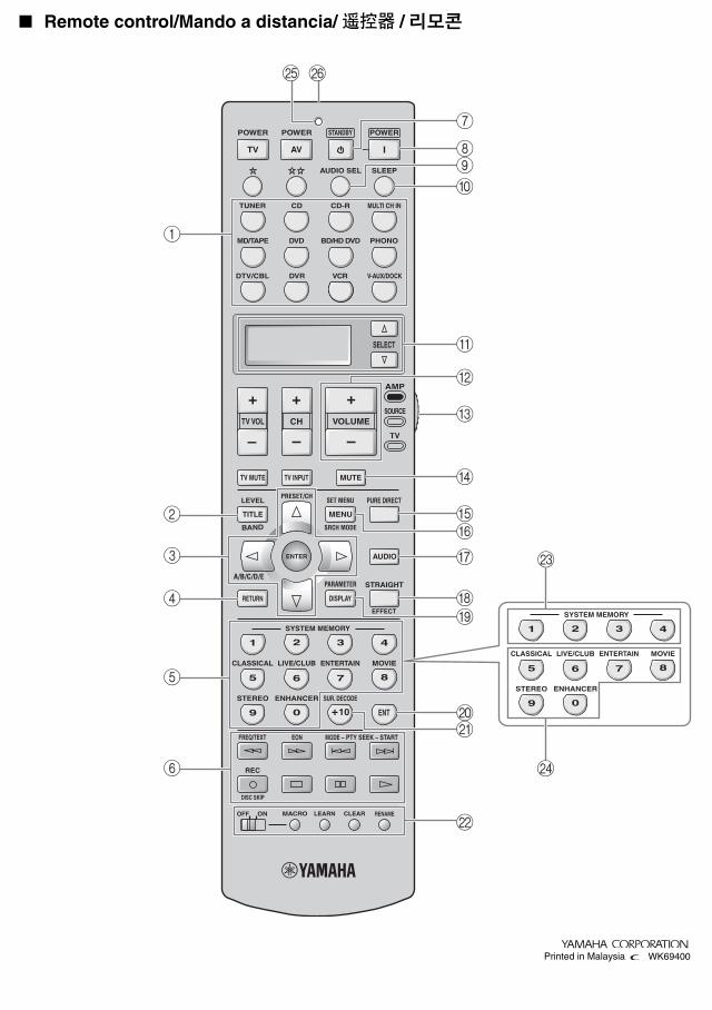
Remote control/Mando a distancia/ 遥控器 / 리모콘
–
+ +
––
+
ENTER
DISPLAY
AUDIO
MENUTITLE
TV MUTE TV INPUT MUTE
432
ENT+1009
5
1
AVTV
76 8
432
09
5
1
76 8
RETURN
ONOFF CLEARLEARN RENAMEMACRO
REC
DISC SKIP
VOLUMECHTV VOL
EFFECT
PARAMETER STRAIGHTA/B/C/D/E
SRCH MODE
PURE DIRECTPRESET/CH
SET MENU
BAND
LEVEL
CLASSICAL LIVE/CLUB ENTERTAIN MOVIE
SYSTEM MEMORY
SUR. DECODE
FREQ/TEXT EON MODE – PTY SEEK – START
ENHANCERSTEREO
TV
SOURCE
AMP
SELECT
DTV/CBL VCRDVR V-AUX/DOCK
TUNER CD CD-R MULTI CH IN
POWER POWER POWERSTANDBY
SLEEPAUDIO SEL
CLASSICAL LIVE/CLUB ENTERTAIN MOVIE
SYSTEM MEMORY
ENHANCERSTEREO
DVD BD/HD DVD PHONOMD/TAPE1
2
3
4
M
PO
5
6
7
8
0
B
A
9
C
FE
D
G
H
L
I
JK
N
WK69400Printed in Malaysia
00_sheet_RX-V1800_ABRTLK.book Page i Friday, June 15, 2007 10:39 PM

YAMAHA ELECTRONICS CORPORATION, USA 6660 ORANGETHORPE AVE., BUENA PARK, CALIF. 90620, U.S.A.YAMAHA CANADA MUSIC LTD. 135 MILNER AVE., SCARBOROUGH, ONTARIO M1S 3R1, CANADAYAMAHA ELECTRONIK EUROPA G.m.b.H. SIEMENSSTR. 22-34, 25462 RELLINGEN BEI HAMBURG, GERMANYYAMAHA ELECTRONIQUE FRANCE S.A. RUE AMBROISE CROIZAT BP70 CROISSY-BEAUBOURG 77312 MARNE-LA-VALLEE CEDEX02, FRANCEYAMAHA ELECTRONICS (UK) LTD. YAMAHA HOUSE, 200 RICKMANSWORTH ROAD WATFORD, HERTS WD18 7GQ, ENGLANDYAMAHA SCANDINAVIA A.B. J A WETTERGRENS GATA 1, BOX 30053, 400 43 VÄSTRA FRÖLUNDA, SWEDENYAMAHA MUSIC AUSTRALIA PTY, LTD. 17-33 MARKET ST., SOUTH MELBOURNE, 3205 VIC., AUSTRALIA
© 2007 All rights reserved.
RX
-V1800
Printed in Malaysia WK69300
RX-V1800AV Receiver
OWNER’S MANUALMANUAL DE INSTRUCCIONES
RTL
RX-V1800_RTL-cv.fm Page 1 Thursday, July 5, 2007 1:26 AM