01en 00 rx-v661 u - yamaha corporation€¦ · yamaha canada music ltd. 135 milner ave.,...
TRANSCRIPT
YAMAHA ELECTRONICS CORPORATION, USA 6660 ORANGETHORPE AVE., BUENA PARK, CALIF. 90620, U.S.A.YAMAHA CANADA MUSIC LTD. 135 MILNER AVE., SCARBOROUGH, ONTARIO M1S 3R1, CANADAYAMAHA ELECTRONIK EUROPA G.m.b.H. SIEMENSSTR. 22-34, 25462 RELLINGEN BEI HAMBURG, GERMANYYAMAHA ELECTRONIQUE FRANCE S.A. RUE AMBROISE CROIZAT BP70 CROISSY-BEAUBOURG 77312 MARNE-LA-VALLEE CEDEX02, FRANCEYAMAHA ELECTRONICS (UK) LTD. YAMAHA HOUSE, 200 RICKMANSWORTH ROAD WATFORD, HERTS WD18 7GQ, ENGLANDYAMAHA SCANDINAVIA A.B. J A WETTERGRENS GATA 1, BOX 30053, 400 43 VÄSTRA FRÖLUNDA, SWEDENYAMAHA MUSIC AUSTRALIA PTY, LTD. 17-33 MARKET ST., SOUTH MELBOURNE, 3205 VIC., AUSTRALIA
© 2007 All rights reserved.
RX-V661
Printed in Malaysia WJ69940
RX-V661AV Receiver
OWNER’S MANUAL
U
RX-V661_U-cv.fm Page 1 Friday, December 8, 2006 7:25 PM
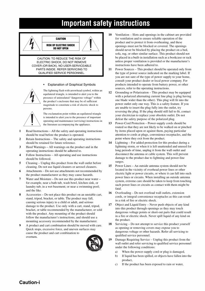
IMPORTANT SAFETY INSTRUCTIONS
• Explanation of Graphical Symbols
The lightning flash with arrowhead symbol, within an equilateral triangle, is intended to alert you to the presence of uninsulated “dangerous voltage” within the product’s enclosure that may be of sufficient magnitude to constitute a risk of electric shock to persons.
The exclamation point within an equilateral triangle is intended to alert you to the presence of important operating and maintenance (servicing) instructions in the literature accompanying the appliance.
1 Read Instructions – All the safety and operating instructions should be read before the product is operated.
2 Retain Instructions – The safety and operating instructions should be retained for future reference.
3 Heed Warnings – All warnings on the product and in the operating instructions should be adhered to.
4 Follow Instructions – All operating and use instructions should be followed.
5 Cleaning – Unplug this product from the wall outlet before cleaning. Do not use liquid cleaners or aerosol cleaners.
6 Attachments – Do not use attachments not recommended by the product manufacturer as they may cause hazards.
7 Water and Moisture – Do not use this product near water – for example, near a bath tub, wash bowl, kitchen sink, or laundry tub; in a wet basement; or near a swimming pool; and the like.
8 Accessories – Do not place this product on an unstable cart, stand, tripod, bracket, or table. The product may fall, causing serious injury to a child or adult, and serious damage to the product. Use only with a cart, stand, tripod, bracket, or table recommended by the manufacturer, or sold with the product. Any mounting of the product should follow the manufacturer’s instructions, and should use a mounting accessory recommended by the manufacturer.
9 A product and cart combination should be moved with care. Quick stops, excessive force, and uneven surfaces may cause the product and cart combination to overturn.
10 Ventilation – Slots and openings in the cabinet are provided for ventilation and to ensure reliable operation of the product and to protect it from overheating, and these openings must not be blocked or covered. The openings should never be blocked by placing the product on a bed, sofa, rug, or other similar surface. This product should not be placed in a built-in installation such as a bookcase or rack unless proper ventilation is provided or the manufacturer’s instructions have been adhered to.
11 Power Sources – This product should be operated only from the type of power source indicated on the marking label. If you are not sure of the type of power supply to your home, consult your product dealer or local power company. For products intended to operate from battery power, or other sources, refer to the operating instructions.
12 Grounding or Polarization – This product may be equipped with a polarized alternating current line plug (a plug having one blade wider than the other). This plug will fit into the power outlet only one way. This is a safety feature. If you are unable to insert the plug fully into the outlet, try reversing the plug. If the plug should still fail to fit, contact your electrician to replace your obsolete outlet. Do not defeat the safety purpose of the polarized plug.
13 Power-Cord Protection – Power-supply cords should be routed so that they are not likely to be walked on or pinched by items placed upon or against them, paying particular attention to cords at plugs, convenience receptacles, and the point where they exit from the product.
14 Lightning – For added protection for this product during a lightning storm, or when it is left unattended and unused for long periods of time, unplug it from the wall outlet and disconnect the antenna or cable system. This will prevent damage to the product due to lightning and power-line surges.
15 Power Lines – An outside antenna system should not be located in the vicinity of overhead power lines or other electric light or power circuits, or where it can fall into such power lines or circuits. When installing an outside antenna system, extreme care should be taken to keep from touching such power lines or circuits as contact with them might be fatal.
16 Overloading – Do not overload wall outlets, extension cords, or integral convenience receptacles as this can result in a risk of fire or electric shock.
17 Object and Liquid Entry – Never push objects of any kind into this product through openings as they may touch dangerous voltage points or short-out parts that could result in a fire or electric shock. Never spill liquid of any kind on the product.
18 Servicing – Do not attempt to service this product yourself as opening or removing covers may expose you to dangerous voltage or other hazards. Refer all servicing to qualified service personnel.
19 Damage Requiring Service – Unplug this product from the wall outlet and refer servicing to qualified service personnel under the following conditions:
a) When the power-supply cord or plug is damaged,b) If liquid has been spilled, or objects have fallen into the
product,c) If the product has been exposed to rain or water,
Important safety instructions
CAUTION
CAUTION: TO REDUCE THE RISK OF ELECTRIC SHOCK, DO NOT REMOVE
COVER (OR BACK). NO USER-SERVICEABLE PARTS INSIDE. REFER SERVICING TO
QUALIFIED SERVICE PERSONNEL.
RISK OF ELECTRIC SHOCK DO NOT OPEN
Caution-i
Important safety instructions
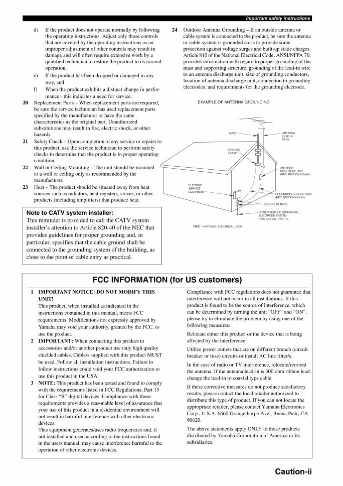
EXAMPLE OF ANTENNA GROUNDING
MAST
GROUNDCLAMP
ANTENNALEAD INWIRE
ANTENNADISCHARGE UNIT(NEC SECTION 810–20)
GROUNDING CONDUCTORS(NEC SECTION 810–21)
GROUND CLAMPS
POWER SERVICE GROUNDINGELECTRODE SYSTEM(NEC ART 250. PART H)
ELECTRICSERVICEEQUIPMENT
NEC – NATIONAL ELECTRICAL CODE
d) If the product does not operate normally by following the operating instructions. Adjust only those controls that are covered by the operating instructions as an improper adjustment of other controls may result in damage and will often require extensive work by a qualified technician to restore the product to its normal operation,
e) If the product has been dropped or damaged in any way, and
f) When the product exhibits a distinct change in perfor-mance - this indicates a need for service.
20 Replacement Parts – When replacement parts are required, be sure the service technician has used replacement parts specified by the manufacturer or have the same characteristics as the original part. Unauthorized substitutions may result in fire, electric shock, or other hazards.
21 Safety Check – Upon completion of any service or repairs to this product, ask the service technician to perform safety checks to determine that the product is in proper operating condition.
22 Wall or Ceiling Mounting – The unit should be mounted to a wall or ceiling only as recommended by the manufacturer.
23 Heat – The product should be situated away from heat sources such as radiators, heat registers, stoves, or other products (including amplifiers) that produce heat.
24 Outdoor Antenna Grounding – If an outside antenna or cable system is connected to the product, be sure the antenna or cable system is grounded so as to provide some protection against voltage surges and built-up static charges. Article 810 of the National Electrical Code, ANSI/NFPA 70, provides information with regard to proper grounding of the mast and supporting structure, grounding of the lead-in wire to an antenna discharge unit, size of grounding conductors, location of antenna discharge unit, connection to grounding electrodes, and requirements for the grounding electrode.
Note to CATV system installer:This reminder is provided to call the CATV system installer’s attention to Article 820-40 of the NEC that provides guidelines for proper grounding and, in particular, specifies that the cable ground shall be connected to the grounding system of the building, as close to the point of cable entry as practical.
FCC INFORMATION (for US customers)1 IMPORTANT NOTICE: DO NOT MODIFY THIS
UNIT!This product, when installed as indicated in the instructions contained in this manual, meets FCC requirements. Modifications not expressly approved by Yamaha may void your authority, granted by the FCC, to use the product.
2 IMPORTANT: When connecting this product to accessories and/or another product use only high quality shielded cables. Cable/s supplied with this product MUST be used. Follow all installation instructions. Failure to follow instructions could void your FCC authorization to use this product in the USA.
3 NOTE: This product has been tested and found to comply with the requirements listed in FCC Regulations, Part 15 for Class “B” digital devices. Compliance with these requirements provides a reasonable level of assurance that your use of this product in a residential environment will not result in harmful interference with other electronic devices.This equipment generates/uses radio frequencies and, if not installed and used according to the instructions found in the users manual, may cause interference harmful to the operation of other electronic devices.
Compliance with FCC regulations does not guarantee that interference will not occur in all installations. If this product is found to be the source of interference, which can be determined by turning the unit “OFF” and “ON”, please try to eliminate the problem by using one of the following measures:
Relocate either this product or the device that is being affected by the interference.
Utilize power outlets that are on different branch (circuit breaker or fuse) circuits or install AC line filter/s.
In the case of radio or TV interference, relocate/reorient the antenna. If the antenna lead-in is 300 ohm ribbon lead, change the lead-in to coaxial type cable.
If these corrective measures do not produce satisfactory results, please contact the local retailer authorized to distribute this type of product. If you can not locate the appropriate retailer, please contact Yamaha Electronics Corp., U.S.A. 6660 Orangethorpe Ave., Buena Park, CA 90620.
The above statements apply ONLY to those products distributed by Yamaha Corporation of America or its subsidiaries.
Caution-ii
CAUTION: READ THIS BEFORE OPERATING YOUR UNIT.
1 To assure the finest performance, please read this manual carefully. Keep it in a safe place for future reference.
2 Install this sound system in a well ventilated, cool, dry, clean place – away from direct sunlight, heat sources, vibration, dust, moisture, and/or cold. Allow ventilation space of at least 30 cm on the top, 20 cm on the left and right, and 20 cm on the back of this unit.
3 Locate this unit away from other electrical appliances, motors, or transformers to avoid humming sounds.
4 Do not expose this unit to sudden temperature changes from cold to hot, and do not locate this unit in an environment with high humidity (i.e. a room with a humidifier) to prevent condensation inside this unit, which may cause an electrical shock, fire, damage to this unit, and/or personal injury.
5 Avoid installing this unit where foreign objects may fall onto this unit and/or this unit may be exposed to liquid dripping or splashing. On the top of this unit, do not place:– Other components, as they may cause damage and/or
discoloration on the surface of this unit.– Burning objects (i.e. candles), as they may cause fire,
damage to this unit, and/or personal injury.– Containers with liquid in them, as they may fall and liquid
may cause electrical shock to the user and/or damage to this unit.
6 Do not cover this unit with a newspaper, tablecloth, curtain, etc. in order not to obstruct heat radiation. If the temperature inside this unit rises, it may cause fire, damage to this unit, and/or personal injury.
7 Do not plug in this unit to a wall outlet until all connections are complete.
8 Do not operate this unit upside-down. It may overheat, possibly causing damage.
9 Do not use force on switches, knobs and/or cords.10 When disconnecting the power cable from the wall outlet,
grasp the plug; do not pull the cable.11 Do not clean this unit with chemical solvents; this might
damage the finish. Use a clean, dry cloth.12 Only voltage specified on this unit must be used. Using this
unit with a higher voltage than specified is dangerous and may cause fire, damage to this unit, and/or personal injury. Yamaha will not be held responsible for any damage resulting from use of this unit with a voltage other than specified.
13 To prevent damage by lightning, keep the power cord and outdoor antennas disconnected from a wall outlet or the unit during a lightning storm.
14 Do not attempt to modify or fix this unit. Contact qualified Yamaha service personnel when any service is needed. The cabinet should never be opened for any reasons.
15 When not planning to use this unit for long periods of time (i.e. vacation), disconnect the AC power plug from the wall outlet.
16 Install this unit near the AC outlet and where the AC power plug can be reached easily.
17 Be sure to read the “TROUBLESHOOTING” section on common operating errors before concluding that this unit is faulty.
18 Before moving this unit, press MASTER ON/OFF to release it outward to the OFF position to turn off this unit, and then disconnect the AC power plug from the AC wall outlet.
19 VOLTAGE SELECTOR (Asia and General models only)The VOLTAGE SELECTOR on the rear panel of this unit must be set for your local main voltage BEFORE plugging into the AC wall outlet. Voltages are:
Asia model ............................ 220/230–240 V AC, 50/60 HzGeneral model ........ 110/120/220/230–240 V AC, 50/60 Hz
20 The batteries shall not be exposed to excessive heat such as sunshine, fire or like.
Caution: Read this before operating your unit.
WARNINGTO REDUCE THE RISK OF FIRE OR ELECTRIC SHOCK, DO NOT EXPOSE THIS UNIT TO RAIN OR MOISTURE.
As long as this unit is connected to the AC wall outlet, it is not disconnected from the AC power source even if you turn off this unit by MASTER ON/OFF. In this state, this unit is designed to consume a very small quantity of power.
FOR CANADIAN CUSTOMERSTo prevent electric shock, match wide blade of plug to wide slot and fully insert.This Class B digital apparatus complies with Canadian ICES-003.
POUR LES CONSOMMATEURS CANADIENSPour éviter les chocs électriques, introduire la lame la plus large de la fiche dans la borne correspondante de la prise et pousser jusqu’au fond.Cet appareil numérique de la classe B est conforme à la norme NMB-003 du Canada.
IMPORTANTPlease record the serial number of this unit in the space below.MODEL: Serial No.: The serial number is located on the rear of the unit. Retain this Owner’s Manual in a safe place for future reference.
Caution-iii
PR
EPA
RA
TIO
NIN
TR
OD
UC
TIO
NB
AS
IC
OP
ER
AT
ION
AD
VAN
CE
D
OP
ER
AT
ION
AD
DIT
ION
AL
IN
FO
RM
AT
ION
AP
PE
ND
IXE
ng
lish
Notice ....................................................................... 2Features ................................................................... 3
Supplied accessories .................................................. 3Getting started ........................................................ 4Quick start guide .................................................... 5
Connections ........................................................... 11Optimizing the speaker setting
for your listening room .................................... 28Using AUTO SETUP .............................................. 28
Selecting the SCENE templates........................... 33Selecting the desired SCENE template.................... 33Creating your original SCENE templates................ 36
Playback ................................................................ 37Basic procedure ....................................................... 37Selecting the MULTI CH INPUT component......... 38Selecting the front speaker set ................................. 38Selecting audio input jacks (AUDIO SELECT)...... 39Displaying the current status of this unit
on a video monitor............................................... 39Using your headphones............................................ 40Muting the audio output........................................... 40Playing video sources
in the background of an audio source.................. 40Displaying the input source information ................. 40Using the sleep timer ............................................... 41
Sound field programs .......................................... 42Selecting sound field programs ............................... 42Sound field program descriptions............................ 42Enjoying unprocessed input sources
(Straight decoding mode) .................................... 47Using audio features ............................................. 48
Enjoying pure hi-fi sound ........................................ 48Adjusting the tonal quality....................................... 48Adjusting the speaker level...................................... 48Enjoying multi-channel sources
in 2-channel stereo............................................... 49Selecting the night listening mode........................... 49
FM/AM tuning ...................................................... 50Automatic tuning ..................................................... 50Manual tuning.......................................................... 50Automatic preset tuning........................................... 51Manual preset tuning ............................................... 51Selecting preset stations........................................... 52Exchanging preset stations ...................................... 52
XM Satellite Radio tuning ................................... 53Connecting the XM Mini-Tuner Dock .................... 53Activating XM Satellite Radio ................................ 54Basic XM Satellite Radio operations....................... 54Setting the XM Satellite Radio preset channels ...... 56Displaying the XM Satellite Radio information...... 57
Using iPod™.......................................................... 58Controlling iPod™................................................... 58
Recording .............................................................. 60
Advanced sound configurations...........................61Changing sound field parameter settings................. 61Selecting decoders ................................................... 66
Customizing this unit (MANUAL SETUP).........69Using SET MENU................................................... 711 SOUND MENU.................................................... 722 INPUT MENU...................................................... 783 OPTION MENU................................................... 81
Remote control features........................................84Using the remote control
for the SCENE feature......................................... 84Controlling this unit, a TV,
or other components ............................................ 85Setting remote control codes ................................... 87Resetting all remote control codes........................... 88
Using multi-zone configuration............................89Connecting Zone 2................................................... 89Controlling Zone 2................................................... 90
Advanced setup......................................................92Using the advanced setup ........................................ 92
Troubleshooting.....................................................96Resetting the system............................................103Glossary................................................................104Sound field program information......................106Parametric equalizer information .....................107Specifications .......................................................108Index .....................................................................110
(at the end of this manual)
Front panel................................................................iRemote control ....................................................... iiList of remote control codes ................................. iii
Contents
INTRODUCTION
PREPARATION
BASIC OPERATION
ADVANCED OPERATION
ADDITIONAL INFORMATION
APPENDIX
“1SPEAKERS” or “ADVD” (example) indicates the name of the parts on the front panel or the remote control. Refer to the attached sheet or the pages at the end of this manual for the information about each position of the parts.
1 En
NOTICE
We Want You Listening For A Lifetime
Yamaha and the Electronic Industries Association’s Consumer Electronics Group want you to get the most out of your equipment by playing it at a safe level. One that lets the sound come through loud and clear without annoying blaring or distortion – and, most importantly, without affecting your sensitive
hearing. Since hearing damage from loud sounds is often undetectable until it is too late, Yamaha and the Electronic Industries Association’s Consumer Electronics Group recommend you to avoid prolonged exposure from excessive volume levels.
Manufactured under license from Dolby Laboratories.“Dolby”, “Pro Logic”, and the double-D symbol are trademarks of Dolby Laboratories.
DTS-ES | NEO:6 | 96/24. Product “DTS” and “DTS-ES | NEO:6” are registered trademarks of DTS, Inc.“96/24” is a trademark of DTS, Inc.
“iPod” is a trademark of Apple Computer, Inc., registered in the U.S. and other countries.
“HDMI”, the “HDMI” logo and “High-Definition Multimedia Interface” are trademarks or registered trademarks of HDMI Licensing LLC.
“SILENT CINEMA” is a trademark of YAMAHA CORPORATION.
The XM name and related logos are registered trademarks of XM Satellite Radio Inc.
Neural Surround™ name and related logos are trademarks owned by Neural Audio Corporation.
Notice
About this manual
• y indicates a tip for your operation.• Some operations can be performed by using either the
buttons on the front panel or the ones on the remote control. In case the button names differ between the front panel and the remote control, the button name on the remote control is given in parentheses.
• This manual is printed prior to production. Design and specifications are subject to change in part as a result of improvements, etc. In case of differences between the manual and product, the product has priority.
• “1SPEAKERS” or “ADVD” (example) indicates the name of the parts on the front panel or the remote control. Refer to the attached sheet or the pages at the end of this manual for the information about each position of the parts.
• The symbol “” with page number(s) indicates the corresponding reference page(s).
iPodTM
2 En
FeaturesIN
TR
OD
UC
TIO
NE
ng
lish
Built-in 7-channel power amplifier Minimum RMS output power
(20 Hz to 20 kHz, 0.06% THD, 8 Ω)Front: 90 W + 90 WCenter: 90 WSurround: 90 W + 90 WSurround back: 90 W + 90 W
SCENE function 18 preset SCENE templates for various situations 4 original SCENE templates for customizing capability Controlling Yamaha SCENE control signal support
component (some models only) working with the SCENE function
Sound field programs Proprietary Yamaha technology for the creation of sound
fields Compressed Music Enhancer mode to improve the sound
quality of compression artifacts (such as the MP3 format) to that of a high-quality stereo
Dolby Digital/Dolby Digital EX decoder DTS/DTS-ES Matrix, Discrete, DTS Neo:6,
DTS 96/24 decoder Dolby Pro Logic/Dolby Pro Logic II/Dolby Pro Logic IIx
decoder Neural Surround decoder Virtual CINEMA DSP SILENT CINEMA
Sophisticated FM/AM tuner 40-station random and direct preset tuning Automatic preset tuning Preset station shifting capability (preset editing)
XM Satellite Radio XM Satellite Radio tuning capability (using the “XM Mini-
Tuner Dock” sold separately) Neural Surround decoder to play back the XM HD content of
XM Satellite Radio broadcasts in multi-channels, resulting in a full surround sound experience
XM Satellite Radio information displaying capability
HDMI (High-Definition Multimedia Interface) HDMI interface for standard, enhanced or high-definition
video (includes 1080p video signal transmission) as well as multi-channel digital audio based on HDMI version 1.2a
iPod controlling capability DOCK terminal to connect a Yamaha iPod universal dock
(such as the YDS-10, sold separately), which supports iPod (Click and Wheel), iPod nano, and iPod mini
Playback information displaying capability Battery charging capability
Other features YPAO (Yamaha Parametric Room Acoustic Optimizer) for
automatic speaker setup 192-kHz/24-bit D/A converter OSD (on-screen display) menus that allow you to optimize
this unit to suit your individual audiovisual system 5.1 or 7.1-channel additional input jacks for discrete multi-
channel input S-video signal input/output capability Component video input/output capability includes
(3 COMPONENT VIDEO INs and 1 MONITOR OUT) Digital video signal conversion (composite video ↔ S-video
→ component video) capability for monitor out Optical and coaxial digital audio signal jacks Pure Direct mode for pure hi-fi sound for all sources Cinema and music night listening modes Remote control with preset remote control codes capability Zone 2 custom installation facility Zone switching capability between the main zone and Zone 2
using ZONE CONTROL Bi-amplification connection capability Sleep timer
Check that you received all of the following parts.
The form of the supplied accessories varies depending on the models.
Features
Supplied accessories
Note
5 6 7 8
9 0 +10 ENT
1 2 3 4
MENUTITLE
SET MENULEVEL
CLASSICAL LIVE/CLUB ENTERTAIN MOVIE
STEREO ENHANCER STRAIGHT PURE DIRECT
SUR. DECODE NIGHT SLEEP
DISPLAYRETURN
BAND SRCH MODE
XM MEMORY
REC
SCENE
A-E/CAT.
ENTER
PRESET/CH
VOLUMETV VOL TV CH
TV MUTE TV INPUT MUTE
AMP
SOURCE
TV
CD CD-R
DVD DTV
MD MULTI CH IN AUDIO SEL
CBL
TUNER
V-AUX
DOCK
DVR VCR
XM
PHONO
STANDBY POWERPOWERPOWER
AVTV
TRANSMITCODE SET
1 2 3 4
Remote control Batteries (2) (AA, R6, UM-3)
AM loop antenna
Optimizer microphone Indoor FM antenna
3 En
GETTING STARTED
Installing batteries in the remote control
1 Take off the battery compartment cover.
2 Insert the two supplied batteries (AA, R6, UM-3) according to the polarity markings (+ and –) on the inside of the battery compartment.
3 Snap the battery compartment cover back into place.
• Change all of the batteries if you notice the following conditions:– the operation range of the remote control decreases.– the VTRANSMIT indicator does not flash or its light
becomes dim.• Do not use an old battery together with a new one.• Do not use different types of batteries (such as alkaline and
manganese batteries) together. Read the packaging carefully as these different types of batteries may have the same shape and color.
• If the batteries have leaked, dispose of them immediately. Avoid touching the leaked material or letting it come into contact with clothing, etc. Clean the battery compartment thoroughly before installing new batteries.
• Do not throw away batteries with general house waste; dispose of them correctly in accordance with your local regulations.
• If the remote control is without batteries for more than 2 minutes, or if exhausted batteries remain in the remote control, the contents of the memory may be cleared. When the memory is cleared, insert new batteries, set up the remote control code and program any acquired functions that may have been cleared.
VOLTAGE SELECTOR(Asia and General models only)
The VOLTAGE SELECTOR on the rear panel of this unit must be set for your local voltage BEFORE plugging the power cable into the AC wall outlet. Improper setting of the VOLTAGE SELECTOR may cause damage to this unit and create a potential fire hazard.
Rotate the VOLTAGE SELECTOR clockwise or counterclockwise to the correct position using a straight slot screwdriver.Voltages are as follows:Asia model .........................220/230–240 V AC, 50/60 HzGeneral model ......110/120/220/230–240 V AC, 50/60 Hz
Getting started
Notes
1 3
2
Caution
230-240V
VOLTAGESELECTOR
Voltage indication
4 En
Quick start guideIN
TR
OD
UC
TIO
NE
ng
lish
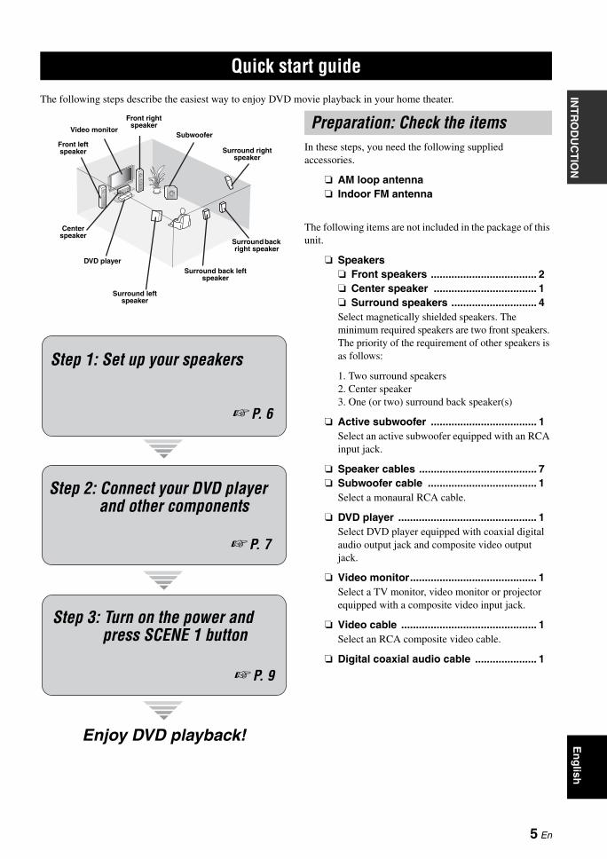
The following steps describe the easiest way to enjoy DVD movie playback in your home theater.
In these steps, you need the following supplied accessories.
AM loop antenna Indoor FM antenna
The following items are not included in the package of this unit.
Speakers Front speakers .................................... 2 Center speaker ................................... 1 Surround speakers ............................. 4Select magnetically shielded speakers. The minimum required speakers are two front speakers. The priority of the requirement of other speakers is as follows:
1. Two surround speakers2. Center speaker3. One (or two) surround back speaker(s)
Active subwoofer .................................... 1Select an active subwoofer equipped with an RCA input jack.
Speaker cables ........................................ 7 Subwoofer cable ..................................... 1
Select a monaural RCA cable.
DVD player ............................................... 1Select DVD player equipped with coaxial digital audio output jack and composite video output jack.
Video monitor........................................... 1Select a TV monitor, video monitor or projector equipped with a composite video input jack.
Video cable .............................................. 1Select an RCA composite video cable.
Digital coaxial audio cable ..................... 1
Quick start guide
Front right speaker
Subwoofer
Surround back right speaker
Surround left speaker
Front left speaker
Surround back left speaker
Surround right speaker
Center speaker
Video monitor
DVD player
Enjoy DVD playback!
Step 1: Set up your speakers
P. 6
Step 2: Connect your DVD player and other components
Step 3: Turn on the power and press SCENE 1 button
P. 7
P. 9
Preparation: Check the items
5 En
Quick start guide
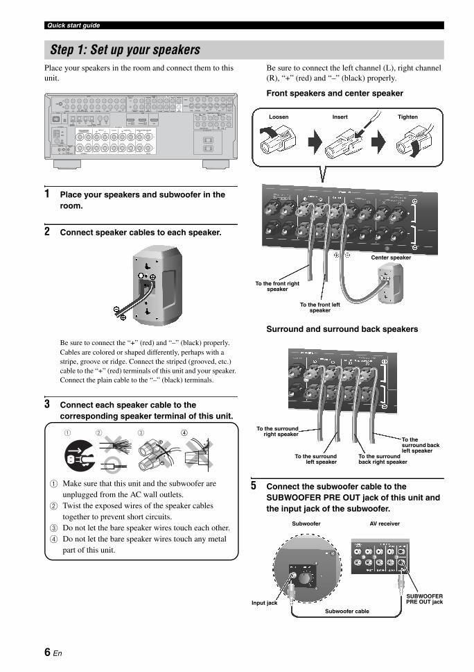
Place your speakers in the room and connect them to this unit.
1 Place your speakers and subwoofer in the room.
2 Connect speaker cables to each speaker.
Be sure to connect the “+” (red) and “–” (black) properly. Cables are colored or shaped differently, perhaps with a stripe, groove or ridge. Connect the striped (grooved, etc.) cable to the “+” (red) terminals of this unit and your speaker. Connect the plain cable to the “–” (black) terminals.
3 Connect each speaker cable to the corresponding speaker terminal of this unit.
1 Make sure that this unit and the subwoofer are unplugged from the AC wall outlets.
2 Twist the exposed wires of the speaker cables together to prevent short circuits.
3 Do not let the bare speaker wires touch each other.4 Do not let the bare speaker wires touch any metal
part of this unit.
Be sure to connect the left channel (L), right channel (R), “+” (red) and “–” (black) properly.
Front speakers and center speaker
Surround and surround back speakers
5 Connect the subwoofer cable to the SUBWOOFER PRE OUT jack of this unit and the input jack of the subwoofer.
Step 1: Set up your speakers
A B
C
PHONO CD (PLAY)IN OUT
(REC) DVD
DVD DTV/CBL CD DVDMD/CD-RMD/CD-R
DTV/CBL
DTV/CBL
DVR
DVD
MONITOR OUT DVR
DVDIN OUT IN OUT
DTV/CBL DVR VCR MONITOROUT
MD/CD-R
OUTINVCR SB(8CH)
FRONT(6CH)
SINGLECENTER CENTER
S VIDEO
VIDEO
OUT
SURROUNDSUB
WOOFERSUB
WOOFERFRONT SURROUND SUR. BACK
MULTI CHINPUT
ZONE 2 PRE OUT VIDEO
OUTIN
GND
FRONT B/ZONE2/ FRONT A CENTER SURROUND
PRESENCE
EXTRA SP
TRIGGER
COMPONENT VIDEO
AC OUTLETS
SPEAKERS
HDMI
AUDIO
ANTENNA
AM
GND
FM
UNBAL
DIGITAL INPUTDIGITALOUTPUT
XMDOCK
OUTREMOTE
+12V15mA MAX.IN OUT
SURROUND BACK/BI-AMP
SINGLE
OPTICAL COAXIALDTV/CBL OUTIN2
75
L
R
L
R
LR
1 2 3 4 5 6
LR L LR R
YPBPR YPBPR
DVD IN1
1 2 3 4
4
To the front left speaker
To the front right speaker
Center speaker
Loosen Insert Tighten
To the surroundright speaker
To the surround back left speaker
To the surround left speaker
To the surround back right speaker
SUBWOOFERPRE OUT jack
Subwoofer cable
Input jack
AV receiverSubwoofer
6 En
Quick start guideIN
TR
OD
UC
TIO
NE
ng
lish
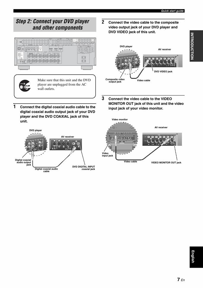
1 Connect the digital coaxial audio cable to the digital coaxial audio output jack of your DVD player and the DVD COAXIAL jack of this unit.
2 Connect the video cable to the composite video output jack of your DVD player and DVD VIDEO jack of this unit.
3 Connect the video cable to the VIDEO MONITOR OUT jack of this unit and the video input jack of your video monitor.
Step 2: Connect your DVD player and other components
A B
C
PHONO CD (PLAY)IN OUT
(REC) DVD
DVD DTV/CBL CD DVDMD/CD-RMD/CD-R
DTV/CBL
DTV/CBL
DVR
DVD
MONITOR OUT DVR
DVDIN OUT IN OUT
DTV/CBL DVR VCR MONITOROUT
MD/CD-R
OUTINVCR SB(8CH)
FRONT(6CH)
SINGLECENTER CENTER
S VIDEO
VIDEO
OUT
SURROUNDSUB
WOOFERSUB
WOOFERFRONT SURROUND SUR. BACK
MULTI CHINPUT
ZONE 2 PRE OUT VIDEO
OUTIN
GND
FRONT B/ZONE2/ FRONT A CENTER SURROUND
PRESENCE
EXTRA SP
TRIGGER
COMPONENT VIDEO
AC OUTLETS
SPEAKERS
HDMI
AUDIO
ANTENNA
AM
GND
FM
UNBAL
DIGITAL INPUTDIGITALOUTPUT
XMDOCK
OUTREMOTE
+12V15mA MAX.IN OUT
SURROUND BACK/BI-AMP
SINGLE
OPTICAL COAXIALDTV/CBL OUTIN2
75
L
R
L
R
LR
1 2 3 4 5 6
LR L LR R
YPBPR YPBPR
DVD IN1
Make sure that this unit and the DVD player are unplugged from the AC wall outlets.
Digital coaxialaudio output
jack
Digital coaxial audio cable
DVD DIGITAL INPUTcoaxial jack
DVD player
AV receiver
Composite video output jack Video cable
DVD VIDEO jack
DVD playerAV receiver
Video monitor
AV receiver
Video cable VIDEO MONITOR OUT jack
Video input jack
7 En
Quick start guide
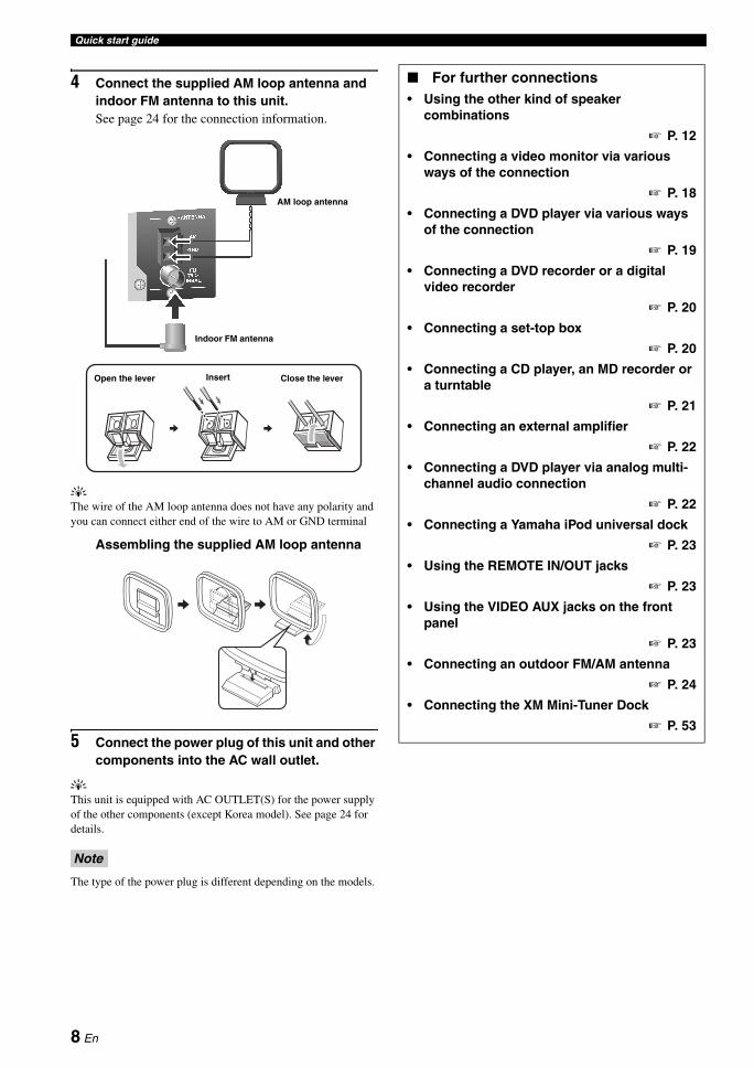
4 Connect the supplied AM loop antenna and indoor FM antenna to this unit.See page 24 for the connection information.
yThe wire of the AM loop antenna does not have any polarity and you can connect either end of the wire to AM or GND terminal
Assembling the supplied AM loop antenna
5 Connect the power plug of this unit and other components into the AC wall outlet.
yThis unit is equipped with AC OUTLET(S) for the power supply of the other components (except Korea model). See page 24 for details.
The type of the power plug is different depending on the models.
Note
Indoor FM antenna
AM loop antenna
Open the lever Insert Close the lever
For further connections• Using the other kind of speaker
combinations
P. 12
• Connecting a video monitor via various ways of the connection
P. 18
• Connecting a DVD player via various ways of the connection
P. 19
• Connecting a DVD recorder or a digital video recorder
P. 20
• Connecting a set-top box
P. 20
• Connecting a CD player, an MD recorder or a turntable
P. 21
• Connecting an external amplifier
P. 22
• Connecting a DVD player via analog multi-channel audio connection
P. 22
• Connecting a Yamaha iPod universal dock
P. 23
• Using the REMOTE IN/OUT jacks
P. 23
• Using the VIDEO AUX jacks on the front panel
P. 23
• Connecting an outdoor FM/AM antenna
P. 24
• Connecting the XM Mini-Tuner Dock
P. 53
8 En
Quick start guideIN
TR
OD
UC
TIO
NE
ng
lish
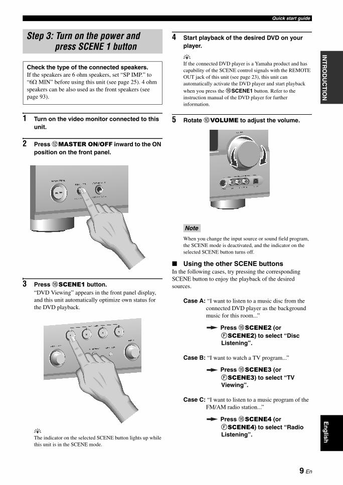
1 Turn on the video monitor connected to this unit.
2 Press BMASTER ON/OFF inward to the ON position on the front panel.
3 Press FSCENE1 button.“DVD Viewing” appears in the front panel display, and this unit automatically optimize own status for the DVD playback.
yThe indicator on the selected SCENE button lights up while this unit is in the SCENE mode.
4 Start playback of the desired DVD on your player.
yIf the connected DVD player is a Yamaha product and has capability of the SCENE control signals with the REMOTE OUT jack of this unit (see page 23), this unit can automatically activate the DVD player and start playback when you press the FSCENE1 button. Refer to the instruction manual of the DVD player for further information.
5 Rotate 0VOLUME to adjust the volume.
When you change the input source or sound field program, the SCENE mode is deactivated, and the indicator on the selected SCENE button turns off.
Using the other SCENE buttonsIn the following cases, try pressing the corresponding SCENE button to enjoy the playback of the desired sources.
Case A: “I want to listen to a music disc from the connected DVD player as the background music for this room...”
Press FSCENE2 (or FSCENE2) to select “Disc Listening”.
Case B: “I want to watch a TV program...”
Press FSCENE3 (or FSCENE3) to select “TV Viewing”.
Case C: “I want to listen to a music program of the FM/AM radio station...”
Press FSCENE4 (or FSCENE4) to select “Radio Listening”.
Step 3: Turn on the power and press SCENE 1 button
Check the type of the connected speakers.If the speakers are 6 ohm speakers, set “SP IMP.” to “6Ω MIN” before using this unit (see page 25). 4 ohm speakers can be also used as the front speakers (see page 93).
Note
9 En
Quick start guide
• To use the “TV Viewing” template (Case B), you must connect a satellite receiver, a cable TV receiver or an HDTV decoder to this unit in advance. See page 20 for details.
• To use the “Radio Listening” template (Case C), you have to tune into the desired radio station. See pages 50 to 52 for the tuning information.
• To achieve the best possible reception, orient the connected AM loop antenna, or adjust the position of the end of the indoor FM antenna.
yIf you cannot find the desired situation, you can select and change the assigned SCENE template for the SCENE buttons. See page 33 for details.
After using this unit...
Press AMAIN ZONE ON/OFF to set this unit to the standby mode.
This unit is set to the standby mode and consumes a small amount of power in order to receive infrared signals from the remote control. To turn on this unit from the standby mode, press the desired FSCENE buttons (or FSCENE) or AMAIN ZONE ON/OFF on the front panel (or HPOWER on the remote control). See page 25 for details.
Notes What do you want to do with this unit?
Customizing the SCENE templates• Using various SCENE templates
P. 33
• Creating your original SCENE templates
P. 36
Using various input sources• Basic controls of this unit
P. 37
• Enjoying FM/AM radio programs
P. 50
• Enjoying XM Satellite Radio programs
P. 53
• Using your iPod with this unit.
P. 58
Using various sound features• Using various sound field programs
P. 42
• Using the pure direct mode for high fidelity sound
P. 48
• Customizing the sound field programs
P. 61
Adjusting the parameters of this unit• Automatically optimizing the speaker
parameters for your listening room (AUTO SETUP)
P. 28
• Manually adjusting various parameters of this unit manually
P. 71
• Setting the remote control
P. 84
• Adjusting the advanced parameters
P. 92
Additional features
Automatically turning off this unit
P. 41
10 En
CONNECTIONSP
RE
PAR
AT
ION
En
glish
Connections
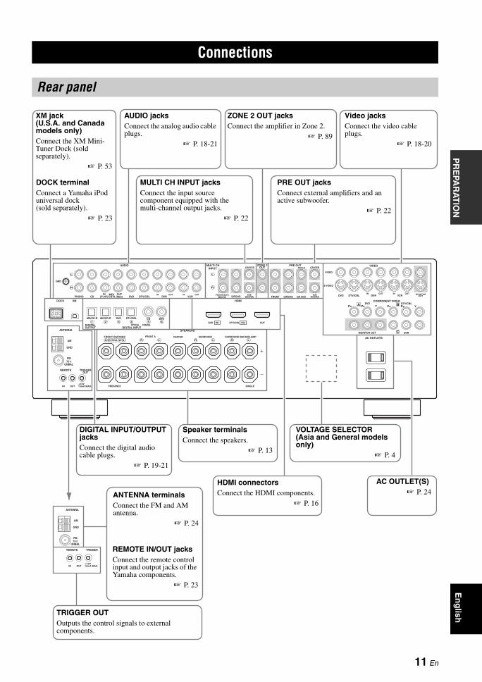
Rear panel
A B
C
PHONO CD (PLAY)IN OUT
(REC) DVD
DVD DTV/CBL CD DVDMD/CD-RMD/CD-R
DTV/CBL
DTV/CBL
DVR
DVD
MONITOR OUT DVR
DVDIN OUT IN OUT
DTV/CBL DVR VCR MONITOROUT
MD/CD-R
OUTINVCR SB(8CH)
FRONT(6CH)
SINGLECENTER CENTER
S VIDEO
VIDEO
OUT
SURROUNDSUB
WOOFERSUB
WOOFERFRONT SURROUND SUR. BACK
MULTI CHINPUT
ZONE 2 PRE OUT VIDEO
OUTIN
GND
FRONT B/ZONE2/ FRONT A CENTER SURROUND
PRESENCE
EXTRA SP
TRIGGER
COMPONENT VIDEO
AC OUTLETS
SPEAKERS
HDMI
AUDIO
ANTENNA
AM
GND
FM
UNBAL
DIGITAL INPUTDIGITALOUTPUT
XMDOCK
OUTREMOTE
+12V15mA MAX.IN OUT
SURROUND BACK/BI-AMP
SINGLE
OPTICAL COAXIALDTV/CBL OUTIN2
75
L
R
L
R
LR
1 2 3 4 5 6
LR L LR R
YPBPR YPBPR
DVD IN1
TRIGGER
ANTENNA
AM
GND
FM
UNBAL
REMOTE
+12V15mA MAX.IN OUT
75
XM jack(U.S.A. and Canada models only)Connect the XM Mini-Tuner Dock (sold separately).
P. 53
DOCK terminalConnect a Yamaha iPod universal dock (sold separately).
P. 23
AUDIO jacksConnect the analog audio cable plugs.
P. 18-21
MULTI CH INPUT jacksConnect the input source component equipped with the multi-channel output jacks.
P. 22
ZONE 2 OUT jacksConnect the amplifier in Zone 2.
P. 89
PRE OUT jacksConnect external amplifiers and an active subwoofer.
P. 22
VOLTAGE SELECTOR (Asia and General models only)
P. 4
HDMI connectorsConnect the HDMI components.
P. 16
TRIGGER OUTOutputs the control signals to external components.
REMOTE IN/OUT jacksConnect the remote control input and output jacks of the Yamaha components.
P. 23
Speaker terminalsConnect the speakers.
P. 13
Video jacksConnect the video cable plugs.
P. 18-20
AC OUTLET(S) P. 24ANTENNA terminals
Connect the FM and AM antenna.
P. 24
DIGITAL INPUT/OUTPUT jacksConnect the digital audio cable plugs.
P. 19-21
11 En
Connections
.
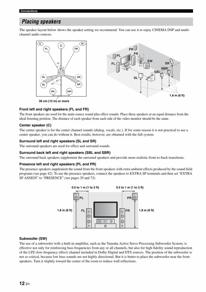
The speaker layout below shows the speaker setting we recommend. You can use it to enjoy CINEMA DSP and multi-channel audio sources.
Front left and right speakers (FL and FR)The front speakers are used for the main source sound plus effect sounds. Place these speakers at an equal distance from the ideal listening position. The distance of each speaker from each side of the video monitor should be the same.
Center speaker (C)The center speaker is for the center channel sounds (dialog, vocals, etc.). If for some reason it is not practical to use a center speaker, you can do without it. Best results, however, are obtained with the full system.
Surround left and right speakers (SL and SR)The surround speakers are used for effect and surround sounds.
Surround back left and right speakers (SBL and SBR)The surround back speakers supplement the surround speakers and provide more realistic front-to-back transitions.
Presence left and right speakers (PL and PR)The presence speakers supplement the sound from the front speakers with extra ambient effects produced by the sound field programs (see page 42). To use the presence speakers, connect the speakers to EXTRA SP terminals and then set “EXTRA SP ASSIGN” to “PRESENCE” (see pages 29 and 72).
Subwoofer (SW)The use of a subwoofer with a built-in amplifier, such as the Yamaha Active Servo Processing Subwoofer System, is effective not only for reinforcing bass frequencies from any or all channels, but also for high fidelity sound reproduction of the LFE (low-frequency effect) channel included in Dolby Digital and DTS sources. The position of the subwoofer is not so critical, because low bass sounds are not highly directional. But it is better to place the subwoofer near the front speakers. Turn it slightly toward the center of the room to reduce wall reflections.
Placing speakers
60˚
30˚
PL PR
SBRSBL
FL FRC
SL
SR
SR80˚
SL
30 cm (12 in) or more
SW
FRPR
PL
FL
SBRSBL
SL
SR
C
1.8 m (6 ft)
FR
PRPL
C
FL 1.8 m (6 ft)
0.5 to 1 m (1 to 3 ft) 0.5 to 1 m (1 to 3 ft)
1.8 m (6 ft)
12 En
ConnectionsP
RE
PAR
AT
ION
En
glish
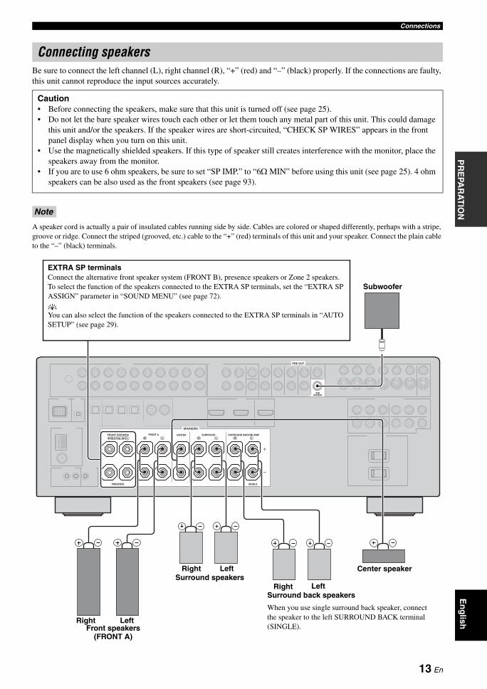
Be sure to connect the left channel (L), right channel (R), “+” (red) and “–” (black) properly. If the connections are faulty, this unit cannot reproduce the input sources accurately.
A speaker cord is actually a pair of insulated cables running side by side. Cables are colored or shaped differently, perhaps with a stripe, groove or ridge. Connect the striped (grooved, etc.) cable to the “+” (red) terminals of this unit and your speaker. Connect the plain cable to the “–” (black) terminals.
Connecting speakers
Caution• Before connecting the speakers, make sure that this unit is turned off (see page 25).• Do not let the bare speaker wires touch each other or let them touch any metal part of this unit. This could damage
this unit and/or the speakers. If the speaker wires are short-circuited, “CHECK SP WIRES” appears in the front panel display when you turn on this unit.
• Use the magnetically shielded speakers. If this type of speaker still creates interference with the monitor, place the speakers away from the monitor.
• If you are to use 6 ohm speakers, be sure to set “SP IMP.” to “6Ω MIN” before using this unit (see page 25). 4 ohm speakers can be also used as the front speakers (see page 93).
Note
SUBWOOFER
PRE OUT
FRONT B/ZONE2/ FRONT A CENTER SURROUND
PRESENCE
EXTRA SP
SPEAKERS
SURROUND BACK/BI-AMP
SINGLE
LR LR L LR R
Front speakers (FRONT A)
Surround speakers
Subwoofer
Right
Center speaker
Surround back speakers
When you use single surround back speaker, connect the speaker to the left SURROUND BACK terminal (SINGLE).
Left
Left
LeftRight
Right
EXTRA SP terminalsConnect the alternative front speaker system (FRONT B), presence speakers or Zone 2 speakers. To select the function of the speakers connected to the EXTRA SP terminals, set the “EXTRA SP ASSIGN” parameter in “SOUND MENU” (see page 72).
yYou can also select the function of the speakers connected to the EXTRA SP terminals in “AUTO SETUP” (see page 29).
13 En
Connections
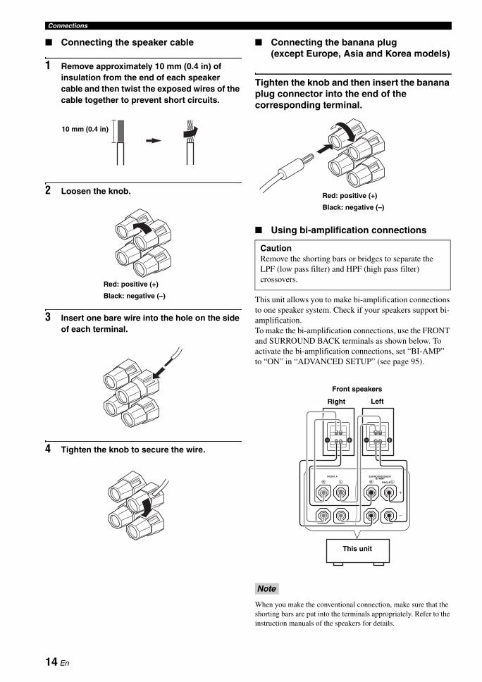
Connecting the speaker cable
1 Remove approximately 10 mm (0.4 in) of insulation from the end of each speaker cable and then twist the exposed wires of the cable together to prevent short circuits.
2 Loosen the knob.
3 Insert one bare wire into the hole on the side of each terminal.
4 Tighten the knob to secure the wire.
Connecting the banana plug (except Europe, Asia and Korea models)
Tighten the knob and then insert the banana plug connector into the end of the corresponding terminal.
Using bi-amplification connections
This unit allows you to make bi-amplification connections to one speaker system. Check if your speakers support bi-amplification. To make the bi-amplification connections, use the FRONT and SURROUND BACK terminals as shown below. To activate the bi-amplification connections, set “BI-AMP” to “ON” in “ADVANCED SETUP” (see page 95).
When you make the conventional connection, make sure that the shorting bars are put into the terminals appropriately. Refer to the instruction manuals of the speakers for details.
10 mm (0.4 in)
Red: positive (+)
Black: negative (–)
CautionRemove the shorting bars or bridges to separate the LPF (low pass filter) and HPF (high pass filter) crossovers.
Note
Red: positive (+)
Black: negative (–)
FRONT A SURROUND BACK/BI-AMP
SINGLELR LR
This unit
LeftRight
Front speakers
14 En
ConnectionsP
RE
PAR
AT
ION
En
glish
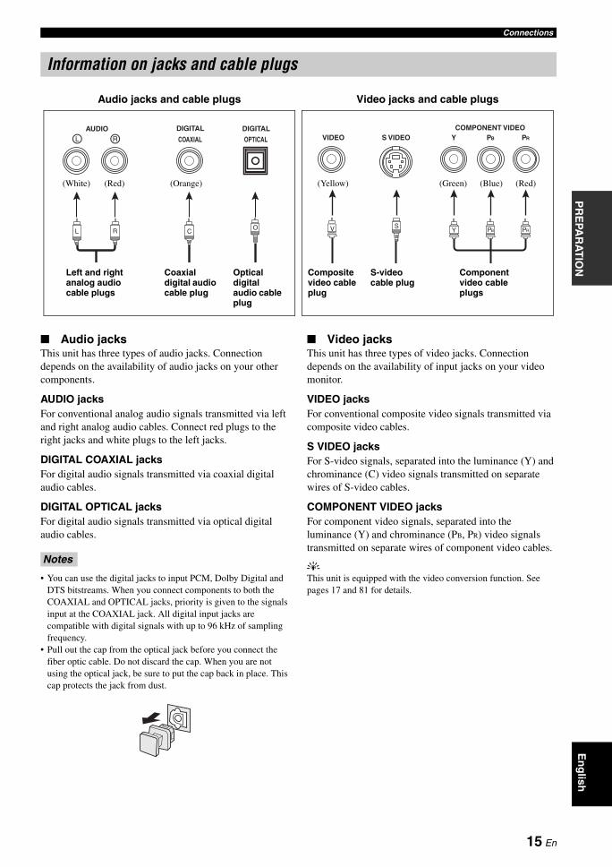
Audio jacksThis unit has three types of audio jacks. Connection depends on the availability of audio jacks on your other components.
AUDIO jacksFor conventional analog audio signals transmitted via left and right analog audio cables. Connect red plugs to the right jacks and white plugs to the left jacks.
DIGITAL COAXIAL jacksFor digital audio signals transmitted via coaxial digital audio cables.
DIGITAL OPTICAL jacksFor digital audio signals transmitted via optical digital audio cables.
• You can use the digital jacks to input PCM, Dolby Digital and DTS bitstreams. When you connect components to both the COAXIAL and OPTICAL jacks, priority is given to the signals input at the COAXIAL jack. All digital input jacks are compatible with digital signals with up to 96 kHz of sampling frequency.
• Pull out the cap from the optical jack before you connect the fiber optic cable. Do not discard the cap. When you are not using the optical jack, be sure to put the cap back in place. This cap protects the jack from dust.
Video jacksThis unit has three types of video jacks. Connection depends on the availability of input jacks on your video monitor.
VIDEO jacksFor conventional composite video signals transmitted via composite video cables.
S VIDEO jacksFor S-video signals, separated into the luminance (Y) and chrominance (C) video signals transmitted on separate wires of S-video cables.
COMPONENT VIDEO jacksFor component video signals, separated into the luminance (Y) and chrominance (PB, PR) video signals transmitted on separate wires of component video cables.
yThis unit is equipped with the video conversion function. See pages 17 and 81 for details.
Information on jacks and cable plugs
VIDEO S VIDEOCOMPONENT VIDEO
Y R PB P
PBY PRSV
COAXIAL
DIGITALAUDIO
OPTICAL
DIGITALRL
CORL
Left and right analog audio cable plugs
Optical digital audio cable plug
Coaxial digital audio cable plug
Composite video cable plug
S-video cable plug
Component video cable plugs
Audio jacks and cable plugs Video jacks and cable plugs
(Red)(White) (Orange) (Yellow) (Green) (Blue) (Red)
Notes
15 En
Connections
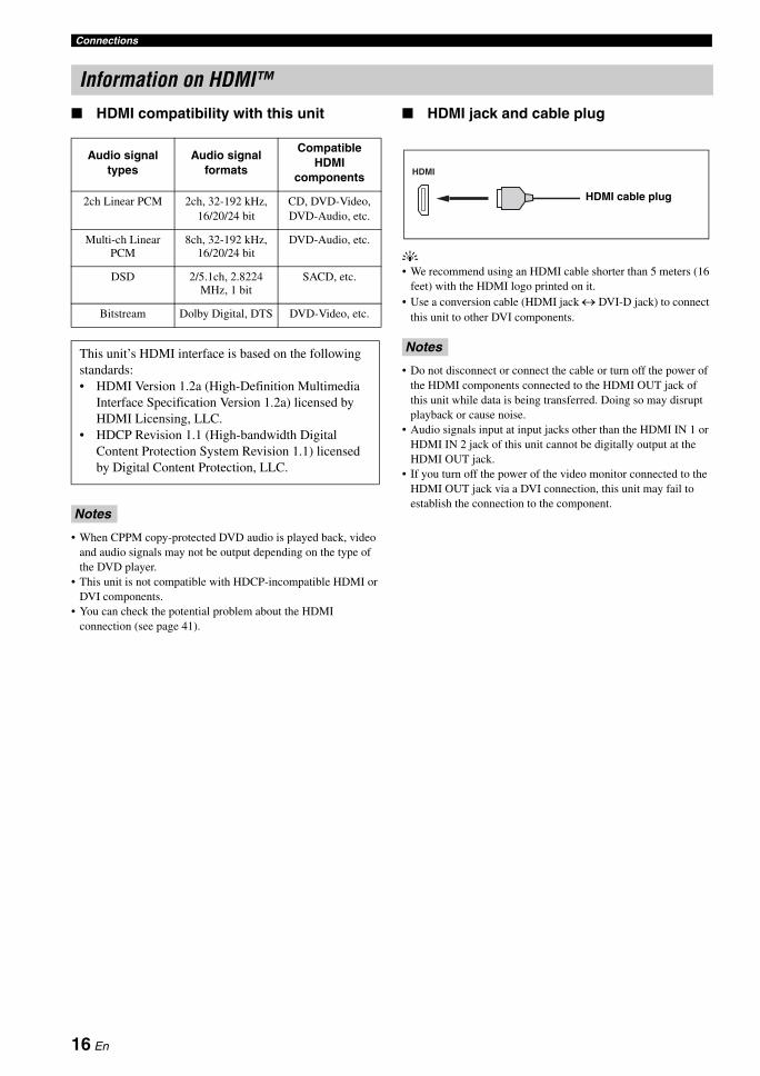
HDMI compatibility with this unit
• When CPPM copy-protected DVD audio is played back, video and audio signals may not be output depending on the type of the DVD player.
• This unit is not compatible with HDCP-incompatible HDMI or DVI components.
• You can check the potential problem about the HDMI connection (see page 41).
HDMI jack and cable plug
y• We recommend using an HDMI cable shorter than 5 meters (16
feet) with the HDMI logo printed on it.• Use a conversion cable (HDMI jack ↔ DVI-D jack) to connect
this unit to other DVI components.
• Do not disconnect or connect the cable or turn off the power of the HDMI components connected to the HDMI OUT jack of this unit while data is being transferred. Doing so may disrupt playback or cause noise.
• Audio signals input at input jacks other than the HDMI IN 1 or HDMI IN 2 jack of this unit cannot be digitally output at the HDMI OUT jack.
• If you turn off the power of the video monitor connected to the HDMI OUT jack via a DVI connection, this unit may fail to establish the connection to the component.
Information on HDMI™
Audio signal types
Audio signal formats
Compatible HDMI
components
2ch Linear PCM 2ch, 32-192 kHz, 16/20/24 bit
CD, DVD-Video, DVD-Audio, etc.
Multi-ch Linear PCM
8ch, 32-192 kHz, 16/20/24 bit
DVD-Audio, etc.
DSD 2/5.1ch, 2.8224 MHz, 1 bit
SACD, etc.
Bitstream Dolby Digital, DTS DVD-Video, etc.
This unit’s HDMI interface is based on the following standards:• HDMI Version 1.2a (High-Definition Multimedia
Interface Specification Version 1.2a) licensed by HDMI Licensing, LLC.
• HDCP Revision 1.1 (High-bandwidth Digital Content Protection System Revision 1.1) licensed by Digital Content Protection, LLC.
Notes
Notes
HDMI
HDMI cable plug
16 En
ConnectionsP
RE
PAR
AT
ION
En
glish
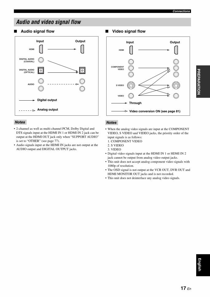
Audio signal flow
• 2-channel as well as multi-channel PCM, Dolby Digital and DTS signals input at the HDMI IN 1 or HDMI IN 2 jack can be output at the HDMI OUT jack only when “SUPPORT AUDIO” is set to “OTHER” (see page 77).
• Audio signals input at the HDMI IN jacks are not output at the AUDIO output and DIGITAL OUTPUT jacks.
Video signal flow
• When the analog video signals are input at the COMPONENT VIDEO, S VIDEO and VIDEO jacks, the priority order of the input signals is as follows: 1. COMPONENT VIDEO2. S VIDEO3. VIDEO
• Digital video signals input at the HDMI IN 1 or HDMI IN 2 jack cannot be output from analog video output jacks.
• This unit does not accept analog component video signals with 1080p of resolution.
• The OSD signal is not output at the VCR OUT, DVR OUT and HDMI MONITOR OUT jacks and is not recorded.
• This unit does not deinterlace any analog video signals.
Audio and video signal flow
Notes
DIGITAL AUDIO(OPTICAL)
DIGITAL AUDIO(COAXIAL)
HDMI
AUDIO
OutputInput
Analog output
Digital output
Notes
S VIDEO
VIDEO
COMPONENTVIDEO
HDMI
Through
OutputInput
Video conversion ON (see page 81)
17 En
Connections
Connect your TV (or projector) to the HDMI OUT jack, the COMPONENT VIDEO MONITOR OUT jacks, the S VIDEO MONITOR OUT jack or the VIDEO MONITOR OUT jack of this unit.
yYou can choose to play back HDMI audio signals on this unit or on another HDMI component connected to the HDMI OUT jack of this unit. Use the “SUPPORT AUDIO” parameter in “SOUND MENU” to select the component to play back HDMI audio signals (see page 77).
• Some video monitors connected to this unit via a DVI connection fail to recognize the HDMI audio/video signals being input if they are in the standby mode. In this case, the HDMI indicator flashes irregularly.
• When you connect your TV monitor or projector via HDMI connection, the OSD does not appear. In such cases, connect the TV monitor or projector via component, S-video or video connection.
• Connect the input source components to the HDMI IN 1 or HDMI IN 2 jack to display the video images on the video monitor connected to the HDMI OUT jack.
Connecting a TV monitor or projector
Make sure that this unit and other components are unplugged from the AC wall outlets.
Notes
MONITOR OUT
MONITOROUT
S VIDEO
VIDEO
VIDEO
COMPONENT VIDEOHDMI
OUT
YPBPR
PR PB
VS
Y
TV (or projector)
Video in
Component video in
S-video in
HDMI in
indicates recommended connections
indicates alternative connections
18 En
ConnectionsP
RE
PAR
AT
ION
En
glish
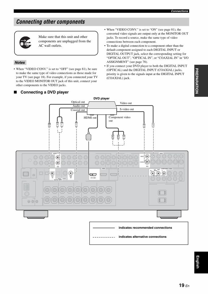
• When “VIDEO CONV.” is set to “OFF” (see page 81), be sure to make the same type of video connections as those made for your TV (see page 18). For example, if you connected your TV to the VIDEO MONITOR OUT jack of this unit, connect your other components to the VIDEO jacks.
• When “VIDEO CONV.” is set to “ON” (see page 81), the converted video signals are output only at the MONITOR OUT jacks. To record a source, make the same type of video connections between each component.
• To make a digital connection to a component other than the default component assigned to each DIGITAL INPUT or DIGITAL OUTPUT jack, select the corresponding setting for “OPTICAL OUT”, “OPTICAL IN”, or “COAXIAL IN” in “I/O ASSIGNMENT” (see page 78).
• If you connect your DVD player to both the DIGITAL INPUT (OPTICAL) and the DIGITAL INPUT (COAXIAL) jacks, priority is given to the signals input at the DIGITAL INPUT (COAXIAL) jack.
Connecting a DVD player
Connecting other components
Notes
Make sure that this unit and other components are unplugged from the AC wall outlets.
A
DVD
DVD DVD
DVD
DVD
S VIDEO
VIDEO
VIDEO
COMPONENT VIDEOHDMI
AUDIO
DIGITAL INPUTOPTICAL COAXIAL
3 6
YPBPR
DVD IN1
LR CO VS
PR PB Y
DVD player
HDMI out Component video out
S-video out
Video outOptical outAudio out
indicates recommended connections
indicates alternative connections
Coaxial out
19 En
Connections
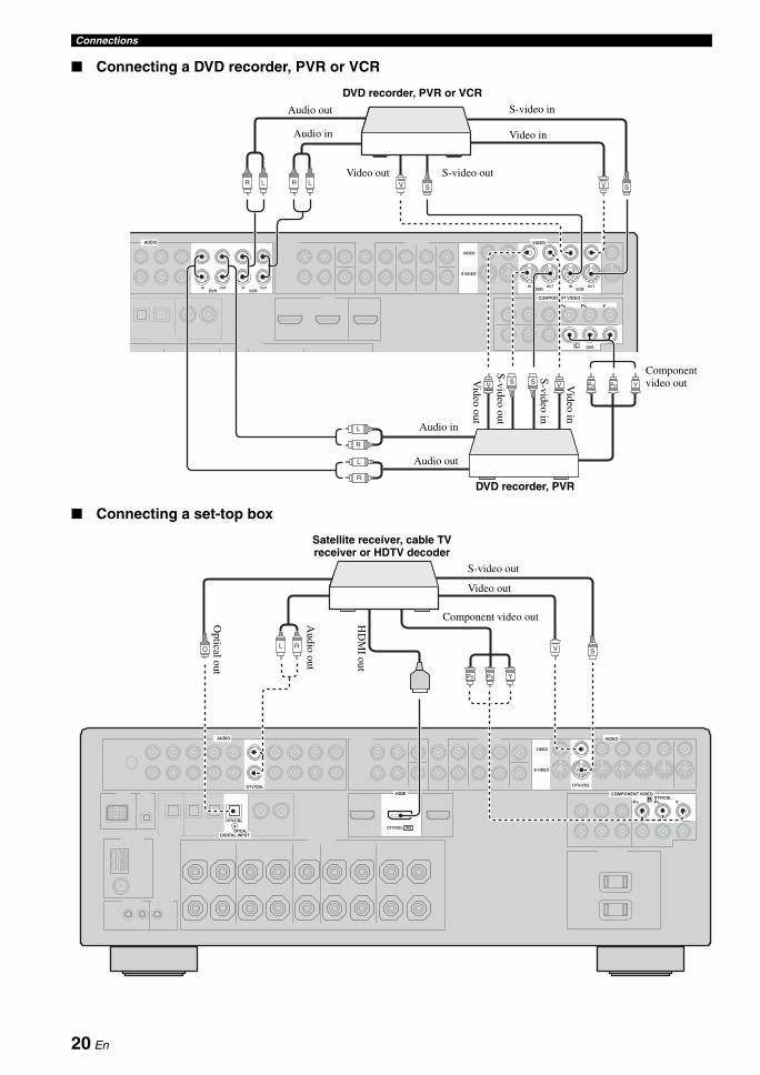
Connecting a DVD recorder, PVR or VCR
Connecting a set-top box
C
DVR
DVR
IN OUT IN OUTDVR VCROUTIN
VCR
S VIDEO
VIDEO
VIDEO
OUTIN
COMPONENT VIDEO
AUDIO
YPBPR
LR V S
V S S V PR PB Y
L
R
L
R
V SLR
S-video in
S-video out
Video out
Audio out
DVD recorder, PVR or VCRS-video in
Video out
Audio out
Audio in
Video in
Component video out
DVD recorder, PVR
Audio in Video in
S-video out
B
DTV/CBL
DTV/CBL
DTV/CBL
DTV/CBL
S VIDEO
VIDEO
VIDEO
COMPONENT VIDEOHDMI
AUDIO
DIGITAL INPUTOPTICAL
DTV/CBL IN24
YPBPR
O VL RS
PR PB Y
Satellite receiver, cable TV receiver or HDTV decoder
HD
MI out
Component video outAudio out
S-video out
Video out
Optical out
20 En
ConnectionsP
RE
PAR
AT
ION
En
glish
Connecting audio components
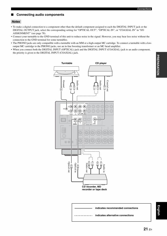
• To make a digital connection to a component other than the default component assigned to each the DIGITAL INPUT jack or the DIGITAL OUTPUT jack, select the corresponding setting for “OPTICAL OUT”, “OPTICAL IN”, or “COAXIAL IN” in “I/O ASSIGNMENT” (see page 78).
• Connect your turntable to the GND terminal of this unit to reduce noise in the signal. However, you may hear less noise without the connection to the GND terminal for some turntables.
• The PHONO jacks are only compatible with a turntable with an MM or a high-output MC cartridge. To connect a turntable with a low-output MC cartridge to the PHONO jacks, use an in-line boosting transformer or an MC-head amplifier.
• When you connect both the DIGITAL INPUT (OPTICAL) jack and the DIGITAL INPUT (COAXIAL) jack to an audio component, the priority is given to the DIGITAL INPUT (COAXIAL) jack.
Notes
PHONO CD (PLAY)IN OUT
(REC)
CDMD/CD-RMD/CD-R
MD/CD-R
GND
AUDIO
DIGITAL INPUTDIGITALOUTPUT
COAXIAL
L
R
1 2 5
RL C
O
R L
O
RL
R L
Turntable
CD recorder, MD recorder or tape deck
Audio in
Optical in
Audio out
Audio out
Ground
indicates recommended connections
indicates alternative connections
CD playerA
udio out
Optical out
Coaxial out
21 En
Connections
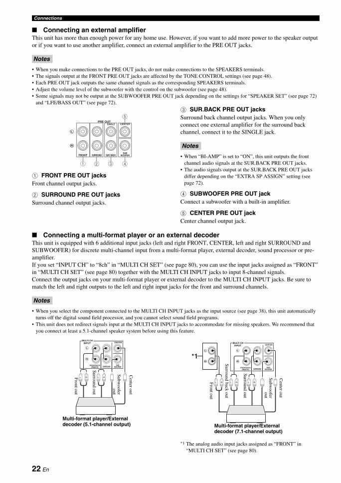
Connecting an external amplifierThis unit has more than enough power for any home use. However, if you want to add more power to the speaker output or if you want to use another amplifier, connect an external amplifier to the PRE OUT jacks.
• When you make connections to the PRE OUT jacks, do not make connections to the SPEAKERS terminals.• The signals output at the FRONT PRE OUT jacks are affected by the TONE CONTROL settings (see page 48).• Each PRE OUT jack outputs the same channel signals as the corresponding SPEAKERS terminals.• Adjust the volume level of the subwoofer with the control on the subwoofer (see page 48).• Some signals may not be output at the SUBWOOFER PRE OUT jack depending on the settings for “SPEAKER SET” (see page 72)
and “LFE/BASS OUT” (see page 72).
1 FRONT PRE OUT jacksFront channel output jacks.
2 SURROUND PRE OUT jacksSurround channel output jacks.
3 SUR.BACK PRE OUT jacksSurround back channel output jacks. When you only connect one external amplifier for the surround back channel, connect it to the SINGLE jack.
• When “BI-AMP” is set to “ON”, this unit outputs the front channel audio signals at the SUR.BACK PRE OUT jacks.
• The audio signals output at the SUR.BACK PRE OUT jacks differ depending on the “EXTRA SP ASSIGN” setting (see page 72).
4 SUBWOOFER PRE OUT jackConnect a subwoofer with a built-in amplifier.
5 CENTER PRE OUT jackCenter channel output jack.
Connecting a multi-format player or an external decoderThis unit is equipped with 6 additional input jacks (left and right FRONT, CENTER, left and right SURROUND and SUBWOOFER) for discrete multi-channel input from a multi-format player, external decoder, sound processor or pre-amplifier.If you set “INPUT CH” to “8ch” in “MULTI CH SET” (see page 80), you can use the input jacks assigned as “FRONT” in “MULTI CH SET” (see page 80) together with the MULTI CH INPUT jacks to input 8-channel signals.Connect the output jacks on your multi-format player or external decoder to the MULTI CH INPUT jacks. Be sure to match the left and right outputs to the left and right input jacks for the front and surround channels.
• When you select the component connected to the MULTI CH INPUT jacks as the input source (see page 38), this unit automatically turns off the digital sound field processor, and you cannot select sound field programs.
• This unit does not redirect signals input at the MULTI CH INPUT jacks to accommodate for missing speakers. We recommend that you connect at least a 5.1-channel speaker system before using this feature.
*1 The analog audio input jacks assigned as “FRONT” in “MULTI CH SET” (see page 80).
Notes
L
R
SINGLE CENTER
SUBWOOFERFRONT SURROUND SUR. BACK
PRE OUT
1 2 3 4
5
Notes
Notes
SB(8CH)FRONT(6CH)
CENTER
SURROUNDSUB
WOOFER
MULTI CHINPUT
L
R
L R L R
Subw
ooferout
Multi-format player/External decoder (5.1-channel output)
Center out
Surround out
Front out
L
R
SB(8CH)FRONT(6CH)
CENTER
SURROUNDSUB
WOOFER
MULTI CHINPUT
L
R
*1
L R L RL R
Multi-format player/External decoder (7.1-channel output)
Front out
Subw
ooferout
Center out
Surround back out
Surround out
22 En
ConnectionsP
RE
PAR
AT
ION
En
glish
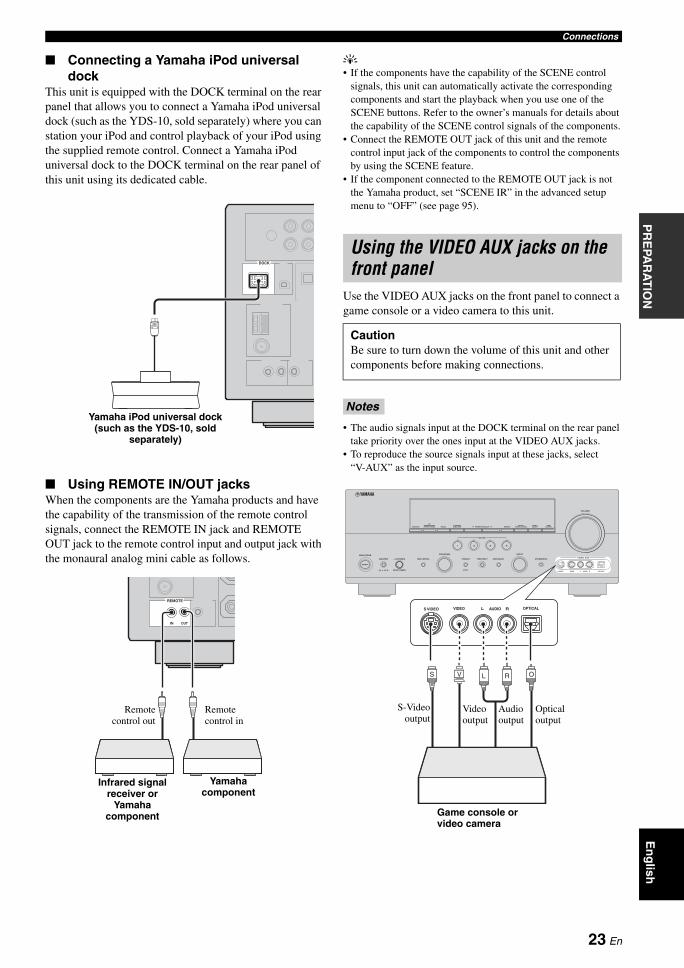
Connecting a Yamaha iPod universal dock
This unit is equipped with the DOCK terminal on the rear panel that allows you to connect a Yamaha iPod universal dock (such as the YDS-10, sold separately) where you can station your iPod and control playback of your iPod using the supplied remote control. Connect a Yamaha iPod universal dock to the DOCK terminal on the rear panel of this unit using its dedicated cable.
Using REMOTE IN/OUT jacksWhen the components are the Yamaha products and have the capability of the transmission of the remote control signals, connect the REMOTE IN jack and REMOTE OUT jack to the remote control input and output jack with the monaural analog mini cable as follows.
y• If the components have the capability of the SCENE control
signals, this unit can automatically activate the corresponding components and start the playback when you use one of the SCENE buttons. Refer to the owner’s manuals for details about the capability of the SCENE control signals of the components.
• Connect the REMOTE OUT jack of this unit and the remote control input jack of the components to control the components by using the SCENE feature.
• If the component connected to the REMOTE OUT jack is not the Yamaha product, set “SCENE IR” in the advanced setup menu to “OFF” (see page 95).
Use the VIDEO AUX jacks on the front panel to connect a game console or a video camera to this unit.
• The audio signals input at the DOCK terminal on the rear panel take priority over the ones input at the VIDEO AUX jacks.
• To reproduce the source signals input at these jacks, select “V-AUX” as the input source.
DOCK
Yamaha iPod universal dock (such as the YDS-10, sold
separately)
REMOTE
IN OUT
Yamaha component
Remotecontrol out
Remote control in
Infrared signal receiver or
Yamaha component
Using the VIDEO AUX jacks on the front panel
CautionBe sure to turn down the volume of this unit and other components before making connections.
Notes
ON/OFF
MAIN ZONE
MASTER PHONES TONE CONTROL
PROGRAM
SPEAKERS PRESET/TUNING FM/AM A/B/C/D/E PRESET/TUNING/CH MEMORY TUNING ON/OFF CONTROLAUTO/MAN'LSEARCH MODE CATEGORY DISPLAY ZONE 2 ZONE
EDIT
STRAIGHT
1 2 3 4
PURE DIRECT
SCENE
AUDIO SELECT
INPUT
VIDEO AUX
VOLUME
OPTIMIZER MIC
S VIDEO VIDEO AUDIO OPTICALL REFFECTSILENT CINEMAON OFF
RL OPTICALAUDIOS VIDEO VIDEO
OVS L R
Game console or video camera
Optical output
Video output
S-Videooutput
Audio output
23 En
Connections
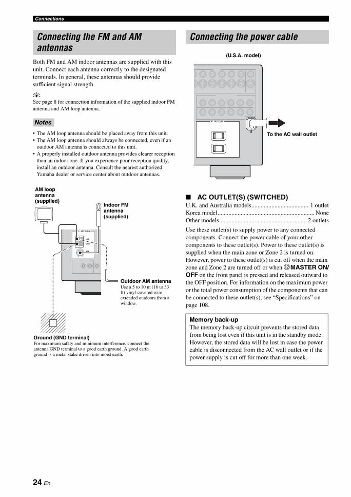
Both FM and AM indoor antennas are supplied with this unit. Connect each antenna correctly to the designated terminals. In general, these antennas should provide sufficient signal strength.
ySee page 8 for connection information of the supplied indoor FM antenna and AM loop antenna.
• The AM loop antenna should be placed away from this unit.• The AM loop antenna should always be connected, even if an
outdoor AM antenna is connected to this unit.• A properly installed outdoor antenna provides clearer reception
than an indoor one. If you experience poor reception quality, install an outdoor antenna. Consult the nearest authorized Yamaha dealer or service center about outdoor antennas.
AC OUTLET(S) (SWITCHED)U.K. and Australia models..................................... 1 outletKorea model............................................................... NoneOther models......................................................... 2 outlets
Use these outlet(s) to supply power to any connected components. Connect the power cable of your other components to these outlet(s). Power to these outlet(s) is supplied when the main zone or Zone 2 is turned on. However, power to these outlet(s) is cut off when the main zone and Zone 2 are turned off or when BMASTER ON/OFF on the front panel is pressed and released outward to the OFF position. For information on the maximum power or the total power consumption of the components that can be connected to these outlet(s), see “Specifications” on page 108.
Connecting the FM and AM antennas
Notes
ANTENNA
AM
GND
FM
Indoor FM antenna (supplied)
Ground (GND terminal)For maximum safety and minimum interference, connect the antenna GND terminal to a good earth ground. A good earth ground is a metal stake driven into moist earth.
AM loop antenna (supplied)
Outdoor AM antennaUse a 5 to 10 m (16 to 33 ft) vinyl-covered wire extended outdoors from a window.
Connecting the power cable
Memory back-upThe memory back-up circuit prevents the stored data from being lost even if this unit is in the standby mode. However, the stored data will be lost in case the power cable is disconnected from the AC wall outlet or if the power supply is cut off for more than one week.
AC OUTLETS
To the AC wall outlet
(U.S.A. model)
24 En
ConnectionsP
RE
PAR
AT
ION
En
glish
1 Make sure this unit is turned off.Refer to the right column for details.
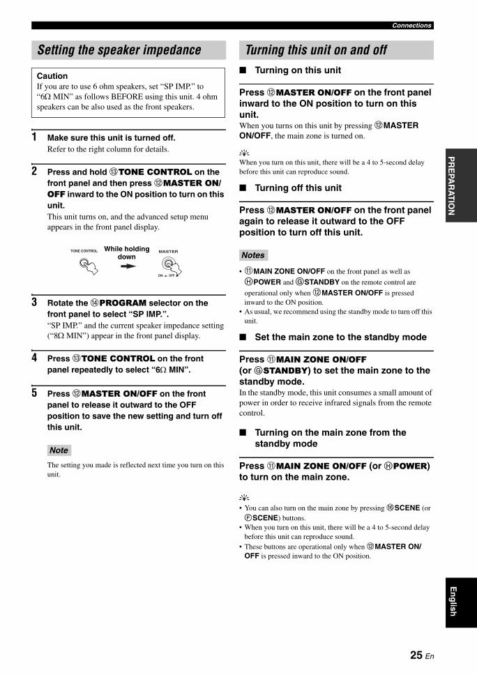
2 Press and hold CTONE CONTROL on the front panel and then press BMASTER ON/OFF inward to the ON position to turn on this unit.This unit turns on, and the advanced setup menu appears in the front panel display.
3 Rotate the DPROGRAM selector on the front panel to select “SP IMP.”.“SP IMP.” and the current speaker impedance setting (“8Ω MIN”) appear in the front panel display.
4 Press CTONE CONTROL on the front panel repeatedly to select “6Ω MIN”.
5 Press BMASTER ON/OFF on the front panel to release it outward to the OFF position to save the new setting and turn off this unit.
The setting you made is reflected next time you turn on this unit.
Turning on this unit
Press BMASTER ON/OFF on the front panel inward to the ON position to turn on this unit.When you turns on this unit by pressing BMASTER ON/OFF, the main zone is turned on.
yWhen you turn on this unit, there will be a 4 to 5-second delay before this unit can reproduce sound.
Turning off this unit
Press BMASTER ON/OFF on the front panel again to release it outward to the OFF position to turn off this unit.
• AMAIN ZONE ON/OFF on the front panel as well as HPOWER and GSTANDBY on the remote control are
operational only when BMASTER ON/OFF is pressed inward to the ON position.
• As usual, we recommend using the standby mode to turn off this unit.
Set the main zone to the standby mode
Press AMAIN ZONE ON/OFF (or GSTANDBY) to set the main zone to the standby mode.In the standby mode, this unit consumes a small amount of power in order to receive infrared signals from the remote control.
Turning on the main zone from the standby mode
Press AMAIN ZONE ON/OFF (or HPOWER) to turn on the main zone.
y• You can also turn on the main zone by pressing FSCENE (or FSCENE) buttons.
• When you turn on this unit, there will be a 4 to 5-second delay before this unit can reproduce sound.
• These buttons are operational only when BMASTER ON/OFF is pressed inward to the ON position.
Setting the speaker impedance
CautionIf you are to use 6 ohm speakers, set “SP IMP.” to “6Ω MIN” as follows BEFORE using this unit. 4 ohm speakers can be also used as the front speakers.
Note
TONE CONTROL MASTER
ON OFF
While holding down
Turning this unit on and off
Notes
25 En
Connections
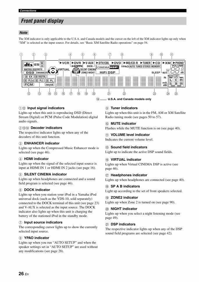
The XM indicator is only applicable to the U.S.A. and Canada models and the cursor on the left of the XM indicator lights up only when “XM” is selected as the input source. For details, see “Basic XM Satellite Radio operations” on page 54.
1B Input signal indicatorsLights up when this unit is reproducing DSD (Direct Stream Digital) or PCM (Pulse Code Modulation) digital audio signals.
2CD Decoder indicatorsThe respective indicator lights up when any of the decoders of this unit function.
3 ENHANCER indicatorLights up when the Compressed Music Enhancer mode is selected (see page 46).
4 HDMI indicatorLights up when the signal of the selected input source is input at HDMI IN 1 or HDMI IN 2 jacks (see page 16).
5 SILENT CINEMA indicatorLights up when headphones are connected and a sound field program is selected (see page 46).
6 DOCK indicatorLights up when you station your iPod in a Yamaha iPod universal dock (such as the YDS-10, sold separately) connected to the DOCK terminal of this unit (see page 23) and V-AUX is selected as the input source. The DOCK indicator also lights up when this unit is charging the battery of the stationed iPod in the standby mode.
7 Input source indicatorsThe corresponding cursor lights up to show the currently selected input source.
8 YPAO indicatorLights up when you run “AUTO SETUP” and when the speaker settings set in “AUTO SETUP” are used without any modifications (see page 28).
9 Tuner indicatorsLights up when this unit is in the FM, AM or XM Satellite Radio tuning mode (see pages 50 to 57).
0 MUTE indicatorFlashes while the MUTE function is on (see page 40).
A VOLUME level indicatorIndicates the current volume level.
E Sound field indicatorsLight up to indicate the active DSP sound fields.
F VIRTUAL indicatorLights up when Virtual CINEMA DSP is active (see page 46).
G Headphones indicatorLights up when headphones are connected (see page 40).
H SP A B indicatorsLight up according to the set of front speakers selected.
I ZONE2 indicatorLights up when Zone 2 is turned on (see page 90).
J NIGHT indicatorLights up when you select a night listening mode (see page 49).
K DSP indicatorsThe respective indicator lights up when any of the DSP sound field programs are selected (see page 42).
Front panel display
Note
VCR DVR DVD CD XMV-AUX DTV/CBL MD/CD-R TUNER PHONO9624
q PL
q EX
q PL
ENHANCERMATRIX DISCRETE SILENT CINEMA
ZONE2 NIGHT
DOCK AUTOYPAO TUNED
MUTE
VOLUMEMEMORY
SLEEPVIRTUAL
PCM
q PL x
DSD
neural
A BSP
mS
ft
dB96/24
HiFi DSPLFE
L C RSL SB SR
q DIGITAL
t
dB
STEREO
GB DC F I J ML ONKE
71 4 65 8 9 A2 3 0
H
D ........ U.S.A. and Canada models only
26 En
ConnectionsP
RE
PAR
AT
ION
En
glish
L Multi-information displayShows the name of the current sound field program and other information when adjusting or changing settings.
M SLEEP indicatorLights up while the sleep timer is on (see page 41).
N 96/24 indicatorLights up when a DTS 96/24 signal is input to this unit.
O Input channel and speaker indicators
LFE indicatorLights up when the input signal contains the LFE signal.
Input channel indicatorsIndicate the channel components of the current digital input signal.
Presence and surround back speaker indicatorsLight up according to the number of presence and surround back speakers set for “EXTRA SP ASSIGN” (see page 72) and “SB L/R SP” (see page 73) in “SOUND MENU” when this unit is in the auto setup (see page 28) or the speaker level setting in “SOUND MENU” (see page 74) procedure.
y• You can make settings for surround back speakers automatically
by running “AUTO SETUP” (see page 28) or manually by adjusting settings for “SB L/R SP” (see page 73) in “SOUND MENU”.
• To use the presence speakers, set “EXTRA SP ASSIGN” to “PRESENCE” (see pages 29 or 72).
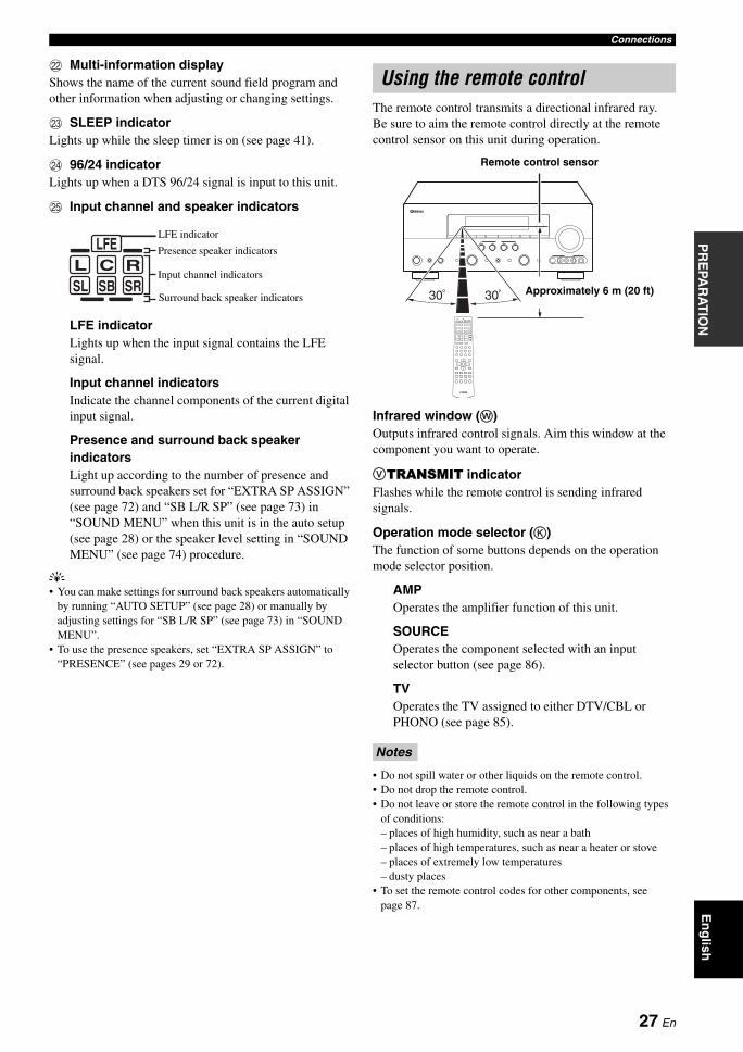
The remote control transmits a directional infrared ray.Be sure to aim the remote control directly at the remote control sensor on this unit during operation.
Infrared window (W)Outputs infrared control signals. Aim this window at the component you want to operate.
VTRANSMIT indicatorFlashes while the remote control is sending infrared signals.
Operation mode selector (K)The function of some buttons depends on the operation mode selector position.
AMPOperates the amplifier function of this unit.
SOURCEOperates the component selected with an input selector button (see page 86).
TVOperates the TV assigned to either DTV/CBL or PHONO (see page 85).
• Do not spill water or other liquids on the remote control.• Do not drop the remote control.• Do not leave or store the remote control in the following types
of conditions:– places of high humidity, such as near a bath– places of high temperatures, such as near a heater or stove– places of extremely low temperatures– dusty places
• To set the remote control codes for other components, see page 87.
Presence speaker indicators
Input channel indicators
Surround back speaker indicators
L C RSL SB SR
LFELFE indicator
Using the remote control
Notes
30 30 Approximately 6 m (20 ft)
Remote control sensor
27 En
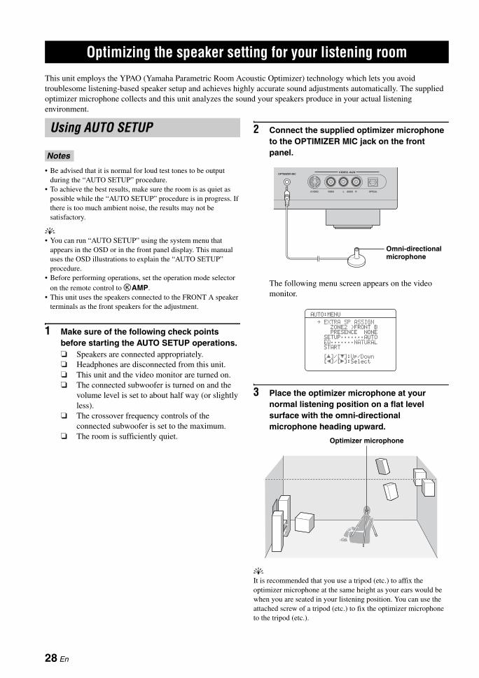
OPTIMIZING THE SPEAKER SETTING FOR YOUR LISTENING ROOM
This unit employs the YPAO (Yamaha Parametric Room Acoustic Optimizer) technology which lets you avoid troublesome listening-based speaker setup and achieves highly accurate sound adjustments automatically. The supplied optimizer microphone collects and this unit analyzes the sound your speakers produce in your actual listening environment.
• Be advised that it is normal for loud test tones to be output during the “AUTO SETUP” procedure.
• To achieve the best results, make sure the room is as quiet as possible while the “AUTO SETUP” procedure is in progress. If there is too much ambient noise, the results may not be satisfactory.
y• You can run “AUTO SETUP” using the system menu that
appears in the OSD or in the front panel display. This manual uses the OSD illustrations to explain the “AUTO SETUP” procedure.
• Before performing operations, set the operation mode selector on the remote control to KAMP.
• This unit uses the speakers connected to the FRONT A speaker terminals as the front speakers for the adjustment.
1 Make sure of the following check points before starting the AUTO SETUP operations. Speakers are connected appropriately. Headphones are disconnected from this unit. This unit and the video monitor are turned on. The connected subwoofer is turned on and the
volume level is set to about half way (or slightly less).
The crossover frequency controls of the connected subwoofer is set to the maximum.
The room is sufficiently quiet.
2 Connect the supplied optimizer microphone to the OPTIMIZER MIC jack on the front panel.
The following menu screen appears on the video monitor.
3 Place the optimizer microphone at your normal listening position on a flat level surface with the omni-directional microphone heading upward.
yIt is recommended that you use a tripod (etc.) to affix the optimizer microphone at the same height as your ears would be when you are seated in your listening position. You can use the attached screw of a tripod (etc.) to fix the optimizer microphone to the tripod (etc.).
Optimizing the speaker setting for your listening room
Using AUTO SETUP
Notes
VIDEO AUXOPTIMIZER MIC
S VIDEO VIDEO AUDIO OPTICALL R
Omni-directional microphone
AUTO:MENU
PRESENCENONE
. EXTRASPASSIGNZONE2 >FRONTB
SETUP;;;;;;;AUTOEQ;;;;;;;NATURALSTART
[ ]/[ ]:Up/Down[]/[]:Select[[
[
[
Optimizer microphone
28 En
Optimizing the speaker setting for your listening roomP
RE
PAR
AT
ION
En
glish
4 Press Dl / h to select the desired setting for “EXTRA SP ASSIGN” and then press Dn.
Extra speaker assignment EXTRA SP ASSIGNSelects the function of the speakers connected to the EXTRA SP terminals.Choices: FRONT B, ZONE2, PRESENCE, NONE
• When you use the alternative front speaker system (see page 38)Select “FRONT B”.
• When you use the Zone 2 speakers (see page 90)Select “ZONE2” to set the function of the speakers to the Zone 2 speakers. This unit drives the Zone 2 speakers by using the internal amplifier.
• When you use the presence speakers (see page 12)Select “PRESENCE” to set the function of the speakers to the presence speakers.
• When you do not use the EXTRA SP terminalsSelect “NONE” to deactivate the EXTRA SP terminals.
If you select “ON” in “BI-AMP” (see page 95), you cannot select “PRESENCE” or “ZONE2” in “EXTRA SP ASSIGN”.
5 Press Dl / h to select “SETUP”.
Choices: AUTO, RELOAD, UNDO, DEFAULT• Select “AUTO” to automatically run the entire
“AUTO SETUP” procedure.• Select “RELOAD” to reload the last “AUTO
SETUP” settings and override the previous settings.
• Select “UNDO” to undo the last “AUTO SETUP” settings and restore the previous settings.
• Select “DEFAULT” to reset the “AUTO SETUP” parameters to the initial factory settings.
• “RELOAD” or “UNDO” is available only when you have previously run “AUTO SETUP” and confirmed the results.
• “RELOAD” or “UNDO” is not available when you change the setting of “BI-AMP” in the advanced setup (see page 95) or “EXTRA SP ASSIGN” in “SOUND MENU” (see page 72).
6 Press Dl / h to select the desired setting of “EQ” and then press Dn.
Parametric equalizer type EQParametric equalizer adjusts the level of the specified frequency bands. This unit automatically selects the crucial frequency bands for the listening room and adjusts the level of the selected frequency bands to create a cohesive sound field in the room. You can select the type of the parametric equalizer adjustment from the following choices.Choices: NATURAL, FLAT, FRONT• Select “NATURAL” to average out the frequency
response of all speakers with higher frequencies being less emphasized. Recommended if the FLAT setting sounds a little harsh.
• Select “FLAT” to average the frequency response of all speakers. Recommended if all of your speakers are of similar quality.
• Select “FRONT” to adjust the frequency response of each speaker in accordance with the sound of your front speakers. Recommended if your front speakers are of much higher quality than your other speakers.
7 Press Dn to select “START” and then press DENTER to start the setup procedure.This unit starts the auto setup procedure. Loud test tones are output from each speaker during the auto setup procedure. Once all items are set, the “AUTO:RESULT” display appears in the OSD.
• During the auto setup procedure, do not perform any operation on this unit.
• We recommend getting out of the room while this unit is in the auto setup procedure. It takes approximately 3 minutes for this unit to complete the auto setup procedure.
Note
Notes
Notes
29 En
Optimizing the speaker setting for your listening room
This unit performs the following checks:
Speaker wiring WIRINGChecks which speakers are connected and the polarity of each speaker.
Speaker size SIZEChecks the frequency response of each speaker and sets the appropriate low-frequency crossover for each channel.
Speaker distance DISTANCEChecks the distance of each speaker from the listening position and adjusts the timing of each channel.
Equalizing EQUALIZINGChecks and adjusts the tonal characteristics of all the speakers by the setting of “EQ”.
Speaker level LEVELChecks and adjusts the volume level of each speaker.
The display changes as follows.
The results displayed under “RESULT” are as follows.
Number of speakers SPDisplays the number of speakers connected to this unit in the following order:Front/Back/Subwoofer
Speaker distance DISTDisplays the speaker distance from the listening position in the following order:Closest speaker distance/Farthest speaker distance
Speaker level LVLDisplays the speaker output level in the following order:Lowest speaker output level/Highest speaker output level
• If “E-10:INTERNAL ERROR” appears during the testing procedure, restart from step 4.
• If you selected “RELOAD” in step 4, no test tones are output.
• If an error occurs during the “AUTO:CHECK” procedure, the setup procedure is canceled and an error screen appears. For details, see “If an error screen appears” on page 32.
• When this unit detects potential problems during the “AUTO SETUP” procedure, “WARNING” and the number of warning messages appears in the above of “RESULT” (see page 32).
• Depending on the listening environment, “SWFR PHASE:REV” appears during the “AUTO:CHECK” procedure and “SUBWOOFER PHASE” in “SOUND MENU” (see page 74) is automatically set to “REVERSE”.
8 Press DENTER to display the setup results in detail.
AUTO:MENU
PRESENCENONE
EXTRASPASSIGNZONE2 >FRONTB
SETUP;;;;;;;AUTOEQ;;;;;;;NATURAL
. START
[ ]/[ ]:Up/Down[]/[]:Select[[
[
[
AUTO:RESULT
. RESULTSP : 3/4/0.1DIST: 14.0/17.0ftLVL : -9.0/+6.5dB
SET CANCEL
[ ]/[ ]:Up/Down[ENTER]:Enter
>
AUTO:CHECK
INITIALIZING. WIRING
SIZE/DISTANCEEQUALIZINGLEVELCHECKCH=CENTER|||||;;;;;;;;
[]:Exit[
Notes
AUTO:RESULT
. RESULTSP : 3/4/0.1DIST: 14.0/17.0ftLVL : -9.0/+6.5dB
SET CANCEL
[ ]/[ ]:Up/Down[ENTER]:Enter
>
RESULT:WIRING
FRONT L;;;;;;;OK
[ ]/[ ]:Select[ENTER]:Return
[[
30 En
Optimizing the speaker setting for your listening roomP
RE
PAR
AT
ION
En
glish
9 Press Dl / h repeatedly to toggle between the setup result displays.
yIf you are not satisfied with the results or want to manually adjust each parameter, run “MANUAL SETUP” (see page 69).
• The distances displayed in the “DISTANCE” results may be longer than the actual distance depending on the characteristics of your subwoofer.
• In the “EQ” results, different values may be set for the same frequency to provide finer adjustments.
10 Press DENTER to return to the top “AUTO:RESULT” display.
11 Make sure the pointer is pointing at “SET” and “CANCEL” and then press Dl / h to select “SET” or “CANCEL”.
Choices: SET, CANCEL• Select “SET” to confirm the “AUTO SETUP”
results.• Select “CANCEL” to cancel the “AUTO SETUP”
results.
12 Press DENTER to confirm your selection.The top “SET MENU” display appears in the OSD.
13 Press NSET MENU to exit from “SET MENU”.
14 Disconnect the optimizer microphone from this unit.The optimizer microphone is sensitive to heat. Keep it away from direct sunlight and do not place it on top of this unit.
yIf you change speakers, speaker positions, or the layout of your listening environment, run “AUTO SETUP” again to recalibrate your system.
Notes
Results of the speaker connection and wiring
Results of the speaker distance from the listening position
Results of the setting of each speaker size
Results of the parametric equalizer of each speaker
Results of the speaker output level
AUTO:RESULT
. RESULTSP : 3/4/0.1DIST: 14.0/17.0ftLVL : -9.0/+6.5dB
SET CANCEL
[ ]/[ ]:Up/Down[ENTER]:Enter
>
AUTO:RESULT
RESULTSP : 3/4/0.1DIST: 14.0/17.0ftLVL : -9.0/+6.5dB
. SET CANCEL
[ ]/[ ]:Up/Down[ENTER]:Enter
>
SET MENU
. ;AUTO SETUP;MANUAL SETUP
.A;SIGNAL INFO
[ ]/[ ]:Up/Down[ENTER]:Enter
p
p
31 En
Optimizing the speaker setting for your listening room
If an error screen appears
Press Dk / n / l / h to select “RETRY” or “EXIT” and then press DENTER.The following display is an example where “E-9:USER CANCEL” appears in the OSD.
Choices: RETRY, EXIT• Select “RETRY” to retry the “AUTO SETUP”
procedure.• Select “EXIT” to exit from the “AUTO SETUP”
procedure.
If “WARNING” appearsWhen this unit detects potential problems during the “AUTO SETUP” procedure, “WARNING” appears in the “AUTO:RESULT” display. Check the warning messages to correct your speaker settings.
Warnings differ from errors in that warnings do not cancel the “AUTO SETUP” procedure.
1 Make sure the pointer is pointing at “WARNING” and then press DENTER to display the detailed information about the warning.The number on the right of “WARNING” indicates the number of warning messages.
2 Press Dl / h repeatedly to toggle between the warning displays.
y• For details about each warning message, see the “AUTO
SETUP” section in “Troubleshooting” on page 101.• When the corresponding warning message is not
applicable to a speaker, “– –” is displayed instead.
3 Press DENTER to return to the top “AUTO:RESULT” display.
Note
AUTO:ERROR
. E-9:USER CANCELDon't operateany function.
>RETRY EXIT
[ ]/[ ]:Select[ENTER]:Enter
[[
AUTO:RESULT
RESULT. WARNING(3)
>SET CANCEL
[ ]/[ ]:Up/Down[ENTER]:Enter
SP : 3/4/0.1DIST: 14.0/17.0ftLVL : -9.0/+6.5dB
WARNING:W-1
<OUT OF PHASE>Reverse ChannelFL --CENTERPL PRSL SRSBL SBR[ ]/[ ]:Select[ENTER]:Return
[[
32 En
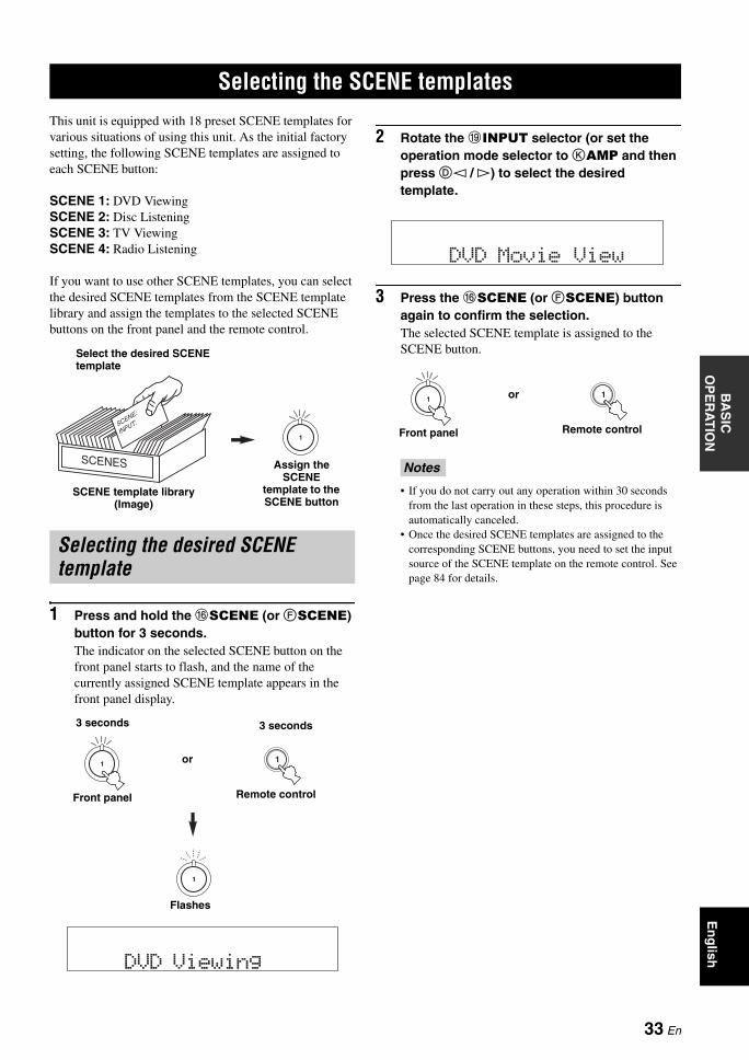
SELECTING THE SCENE TEMPLATESB
AS
IC
OP
ER
AT
ION
En
glish
This unit is equipped with 18 preset SCENE templates for various situations of using this unit. As the initial factory setting, the following SCENE templates are assigned to each SCENE button:
SCENE 1: DVD ViewingSCENE 2: Disc ListeningSCENE 3: TV ViewingSCENE 4: Radio Listening
If you want to use other SCENE templates, you can select the desired SCENE templates from the SCENE template library and assign the templates to the selected SCENE buttons on the front panel and the remote control.
1 Press and hold the FSCENE (or FSCENE) button for 3 seconds.The indicator on the selected SCENE button on the front panel starts to flash, and the name of the currently assigned SCENE template appears in the front panel display.
2 Rotate the IINPUT selector (or set the operation mode selector to KAMP and then press Dl / h) to select the desired template.
3 Press the FSCENE (or FSCENE) button again to confirm the selection.The selected SCENE template is assigned to the SCENE button.
• If you do not carry out any operation within 30 seconds from the last operation in these steps, this procedure is automatically canceled.
• Once the desired SCENE templates are assigned to the corresponding SCENE buttons, you need to set the input source of the SCENE template on the remote control. See page 84 for details.
Selecting the SCENE templates
Selecting the desired SCENE template
1
SCENE template library (Image)
Select the desired SCENE template
Assign the SCENE
template to the SCENE button
1
DVD Viewing
1
1
or
Remote control
Flashes
3 seconds 3 seconds
Front panel
Notes
DVD MovieView
11or
Remote controlFront panel
33 En
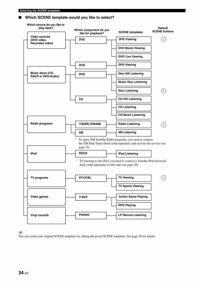
Selecting the SCENE templates
Which SCENE template would you like to select?
yYou can create your original SCENE templates by editing the preset SCENE templates. See page 36 for details.
1
2
3
4Radio Listening
CD Hifi Listening
CD Listening
CD Music Listening
XM Listening
iPod Listening
DVD Live Viewing
DVD Movie Viewing
DVD Viewing
Disc Hifi Listening
Music Disc Listening
Disc Listening
DVR Viewing
TV Viewing
Action Game Playing
RPG Playing
DVD
V-AUX
PHONO
DTV/CBL
TUNER (FM/AM)
DOCK
CD
DVD
DVR
Video sources (DVD video, Recorded video)
TV programs
Video games
iPod
Radio programs
Music discs (CD, SACD or DVD-Audio)
SCENE templatesWhich component do you
like for playback?
Vinyl records
Which source do you like to play back?
LP Record Listening
XM
Default SCENE buttons
* To enjoy XM Satellite Radio programs, you need to connect the XM Mini-Tuner Dock (sold separately) and activate the service (see page 53).
TV Sports Viewing
* To listening to the iPod, you need to connect a Yamaha iPod universal dock (sold separately) to this unit (see page 58).
34 En
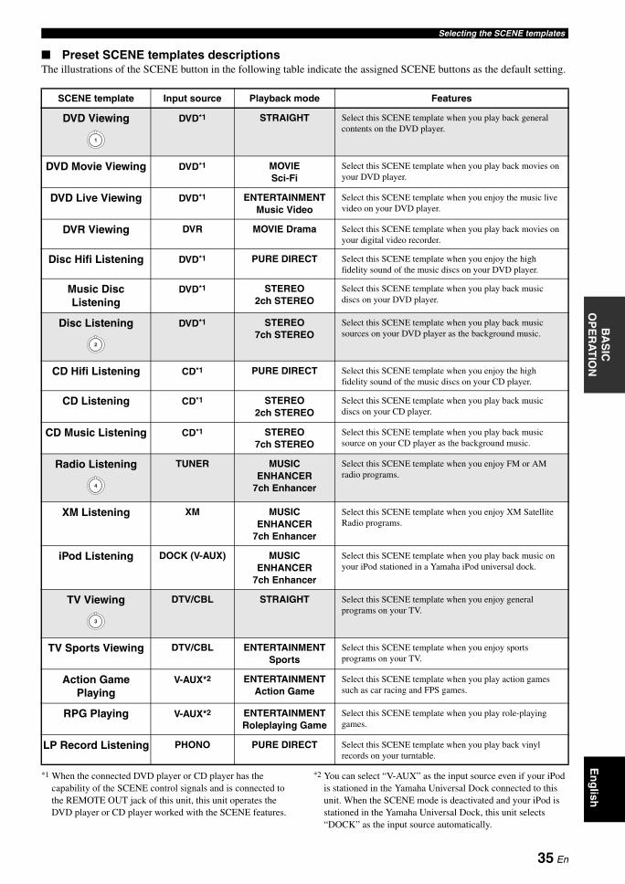
Selecting the SCENE templatesB
AS
IC
OP
ER
AT
ION
En
glish
Preset SCENE templates descriptionsThe illustrations of the SCENE button in the following table indicate the assigned SCENE buttons as the default setting.
*1 When the connected DVD player or CD player has the capability of the SCENE control signals and is connected to the REMOTE OUT jack of this unit, this unit operates the DVD player or CD player worked with the SCENE features.
*2 You can select “V-AUX” as the input source even if your iPod is stationed in the Yamaha Universal Dock connected to this unit. When the SCENE mode is deactivated and your iPod is stationed in the Yamaha Universal Dock, this unit selects “DOCK” as the input source automatically.
SCENE template Input source Playback mode Features
DVD Viewing DVD*1 STRAIGHT Select this SCENE template when you play back general contents on the DVD player.
DVD Movie Viewing DVD*1 MOVIESci-Fi
Select this SCENE template when you play back movies on your DVD player.
DVD Live Viewing DVD*1 ENTERTAINMENTMusic Video
Select this SCENE template when you enjoy the music live video on your DVD player.
DVR Viewing DVR MOVIE Drama Select this SCENE template when you play back movies on your digital video recorder.
Disc Hifi Listening DVD*1 PURE DIRECT Select this SCENE template when you enjoy the high fidelity sound of the music discs on your DVD player.
Music Disc Listening
DVD*1 STEREO2ch STEREO
Select this SCENE template when you play back music discs on your DVD player.
Disc Listening DVD*1 STEREO7ch STEREO
Select this SCENE template when you play back music sources on your DVD player as the background music.
CD Hifi Listening CD*1 PURE DIRECT Select this SCENE template when you enjoy the high fidelity sound of the music discs on your CD player.
CD Listening CD*1 STEREO2ch STEREO
Select this SCENE template when you play back music discs on your CD player.
CD Music Listening CD*1 STEREO7ch STEREO
Select this SCENE template when you play back music source on your CD player as the background music.
Radio Listening TUNER MUSIC ENHANCER
7ch Enhancer
Select this SCENE template when you enjoy FM or AM radio programs.
XM Listening XM MUSIC ENHANCER
7ch Enhancer
Select this SCENE template when you enjoy XM Satellite Radio programs.
iPod Listening DOCK (V-AUX) MUSIC ENHANCER
7ch Enhancer
Select this SCENE template when you play back music on your iPod stationed in a Yamaha iPod universal dock.
TV Viewing DTV/CBL STRAIGHT Select this SCENE template when you enjoy general programs on your TV.
TV Sports Viewing DTV/CBL ENTERTAINMENTSports
Select this SCENE template when you enjoy sports programs on your TV.
Action Game Playing
V-AUX*2 ENTERTAINMENTAction Game
Select this SCENE template when you play action games such as car racing and FPS games.
RPG Playing V-AUX*2 ENTERTAINMENTRoleplaying Game
Select this SCENE template when you play role-playing games.
LP Record Listening PHONO PURE DIRECT Select this SCENE template when you play back vinyl records on your turntable.
1
2
4
3
35 En
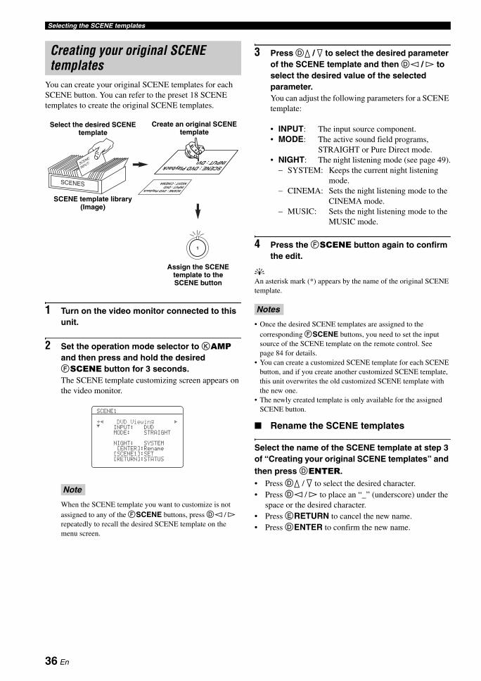
Selecting the SCENE templates
You can create your original SCENE templates for each SCENE button. You can refer to the preset 18 SCENE templates to create the original SCENE templates.
1 Turn on the video monitor connected to this unit.
2 Set the operation mode selector to KAMP and then press and hold the desired FSCENE button for 3 seconds.The SCENE template customizing screen appears on the video monitor.
When the SCENE template you want to customize is not assigned to any of the FSCENE buttons, press Dl / h repeatedly to recall the desired SCENE template on the menu screen.
3 Press Dk / n to select the desired parameter of the SCENE template and then Dl / h to select the desired value of the selected parameter.You can adjust the following parameters for a SCENE template:
• INPUT: The input source component.• MODE: The active sound field programs,
STRAIGHT or Pure Direct mode.• NIGHT: The night listening mode (see page 49).
− SYSTEM: Keeps the current night listening mode.
− CINEMA: Sets the night listening mode to the CINEMA mode.
− MUSIC: Sets the night listening mode to the MUSIC mode.
4 Press the FSCENE button again to confirm the edit.
yAn asterisk mark (*) appears by the name of the original SCENE template.
• Once the desired SCENE templates are assigned to the corresponding FSCENE buttons, you need to set the input source of the SCENE template on the remote control. See page 84 for details.
• You can create a customized SCENE template for each SCENE button, and if you create another customized SCENE template, this unit overwrites the old customized SCENE template with the new one.
• The newly created template is only available for the assigned SCENE button.
Rename the SCENE templates
Select the name of the SCENE template at step 3 of “Creating your original SCENE templates” and then press DENTER.• Press Dk / n to select the desired character.• Press Dl / h to place an “_” (underscore) under the
space or the desired character.• Press ERETURN to cancel the new name.• Press DENTER to confirm the new name.
Creating your original SCENE templates
Note
1
SCENE template library (Image)
Select the desired SCENE template
Assign the SCENE template to the SCENE button
Create an original SCENE template
[RETURN]:STATUS[SCENE1]:SET[ENTER]:RenameNIGHT:SYSTEMMODE:STRAIGHTINPUT: DVD.pDVDViewing[SCENE1
[
Notes
36 En
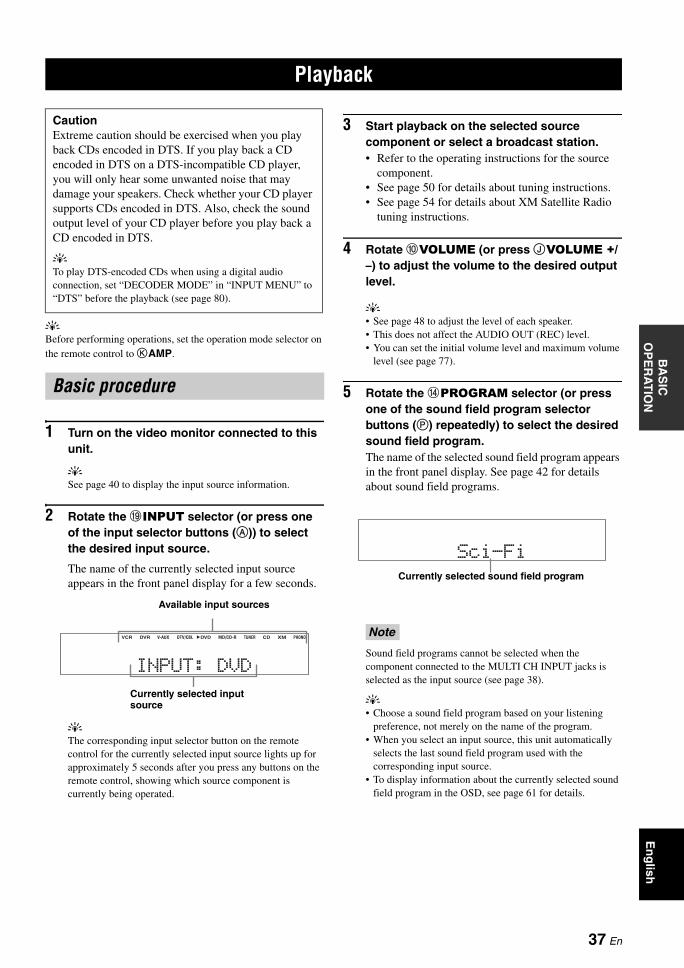
PLAYBACKB
AS
IC
OP
ER
AT
ION
En
glish
yBefore performing operations, set the operation mode selector on the remote control to KAMP.
1 Turn on the video monitor connected to this unit.
ySee page 40 to display the input source information.
2 Rotate the IINPUT selector (or press one of the input selector buttons (A)) to select the desired input source.
The name of the currently selected input source appears in the front panel display for a few seconds.
yThe corresponding input selector button on the remote control for the currently selected input source lights up for approximately 5 seconds after you press any buttons on the remote control, showing which source component is currently being operated.
3 Start playback on the selected source component or select a broadcast station.• Refer to the operating instructions for the source
component.• See page 50 for details about tuning instructions.• See page 54 for details about XM Satellite Radio
tuning instructions.
4 Rotate 0VOLUME (or press JVOLUME +/–) to adjust the volume to the desired output level.
y• See page 48 to adjust the level of each speaker.• This does not affect the AUDIO OUT (REC) level.• You can set the initial volume level and maximum volume
level (see page 77).
5 Rotate the DPROGRAM selector (or press one of the sound field program selector buttons (P) repeatedly) to select the desired sound field program.The name of the selected sound field program appears in the front panel display. See page 42 for details about sound field programs.
Sound field programs cannot be selected when the component connected to the MULTI CH INPUT jacks is selected as the input source (see page 38).
y• Choose a sound field program based on your listening
preference, not merely on the name of the program.• When you select an input source, this unit automatically
selects the last sound field program used with the corresponding input source.
• To display information about the currently selected sound field program in the OSD, see page 61 for details.
Playback
CautionExtreme caution should be exercised when you play back CDs encoded in DTS. If you play back a CD encoded in DTS on a DTS-incompatible CD player, you will only hear some unwanted noise that may damage your speakers. Check whether your CD player supports CDs encoded in DTS. Also, check the sound output level of your CD player before you play back a CD encoded in DTS.
yTo play DTS-encoded CDs when using a digital audio connection, set “DECODER MODE” in “INPUT MENU” to “DTS” before the playback (see page 80).
Basic procedure
INPUT:DVD
VCR DVR DVD CD XMV-AUX DTV/CBL MD/CD-R TUNER PHONO
Currently selected input source
Available input sources
Note
Sci-FiCurrently selected sound field program
37 En
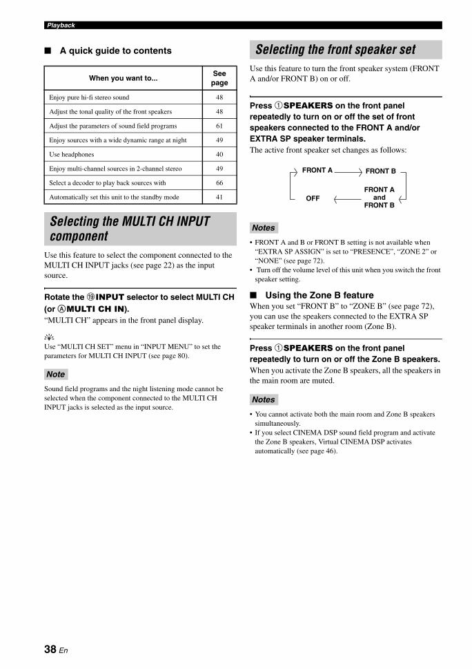
Playback
A quick guide to contents
Use this feature to select the component connected to the MULTI CH INPUT jacks (see page 22) as the input source.
Rotate the IINPUT selector to select MULTI CH (or AMULTI CH IN).“MULTI CH” appears in the front panel display.
yUse “MULTI CH SET” menu in “INPUT MENU” to set the parameters for MULTI CH INPUT (see page 80).
Sound field programs and the night listening mode cannot be selected when the component connected to the MULTI CH INPUT jacks is selected as the input source.
Use this feature to turn the front speaker system (FRONT A and/or FRONT B) on or off.
Press 1SPEAKERS on the front panel repeatedly to turn on or off the set of front speakers connected to the FRONT A and/or EXTRA SP speaker terminals.The active front speaker set changes as follows:
• FRONT A and B or FRONT B setting is not available when “EXTRA SP ASSIGN” is set to “PRESENCE”, “ZONE 2” or “NONE” (see page 72).
• Turn off the volume level of this unit when you switch the front speaker setting.
Using the Zone B featureWhen you set “FRONT B” to “ZONE B” (see page 72), you can use the speakers connected to the EXTRA SP speaker terminals in another room (Zone B).
Press 1SPEAKERS on the front panel repeatedly to turn on or off the Zone B speakers.When you activate the Zone B speakers, all the speakers in the main room are muted.
• You cannot activate both the main room and Zone B speakers simultaneously.
• If you select CINEMA DSP sound field program and activate the Zone B speakers, Virtual CINEMA DSP activates automatically (see page 46).
When you want to...See
page
Enjoy pure hi-fi stereo sound 48
Adjust the tonal quality of the front speakers 48
Adjust the parameters of sound field programs 61
Enjoy sources with a wide dynamic range at night 49
Use headphones 40
Enjoy multi-channel sources in 2-channel stereo 49
Select a decoder to play back sources with 66
Automatically set this unit to the standby mode 41
Selecting the MULTI CH INPUT component
Note
Selecting the front speaker set
Notes
Notes
FRONT A FRONT B
FRONT A and
FRONT BOFF
38 En
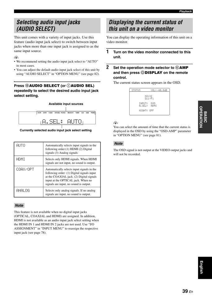
PlaybackB
AS
IC
OP
ER
AT
ION
En
glish
This unit comes with a variety of input jacks. Use this feature (audio input jack select) to switch between input jacks when more than one input jack is assigned to as the same input source.
y• We recommend setting the audio input jack select to “AUTO”
in most cases.• You can adjust the default audio input jack select of this unit by
using “AUDIO SELECT” in “OPTION MENU” (see page 82).
Press HAUDIO SELECT (or IAUDIO SEL) repeatedly to select the desired audio input jack select setting.
This feature is not available when no digital input jacks (OPTICAL, COAXIAL and HDMI) are assigned. In addition, HDMI is not available as an audio input jack select setting when the HDMI IN 1 and HDMI IN 2 jacks are not used. Use “I/O ASSIGNMENT” in “INPUT MENU” to reassign the respective input jack (see page 78).
You can display the operating information of this unit on a video monitor.
1 Turn on the video monitor connected to this unit.
2 Set the operation mode selector to KAMP and then press ODISPLAY on the remote control.The current status screen appears in the OSD.
yYou can select the amount of time that the current status is displayed in the OSD by using the “OSD-AMP” parameter in “OPTION MENU” (see page 81).
The OSD signal is not output at the VIDEO output jacks and will not be recorded.
Selecting audio input jacks (AUDIO SELECT)
AUTO Automatically selects input signals in the following order:(1) HDMI (2) Digital signals (3) Analog signals
HDMI Selects only HDMI signals. When HDMI signals are not input, no sound is output.
COAX/OPT Automatically selects input signals in the following order: (1) Digital signals input at the COAXIAL jack. (2) Digital signals input at the OPTICAL jack. When no signals are input, no sound is output.
ANALOG Selects only analog signals. If no analog signals are input, no sound is output.
Note
A.SEL:AUTO
VCR DVR DVD CD XMV-AUX DTV/CBL MD/CD-R TUNER PHONO
Currently selected audio input jack select setting
Available input sources
Displaying the current status of this unit on a video monitor
Note
NIGHT:OFFA.SEL:HDMIINPUT:DVDSci-FiMOVIE
STATUSVOL:-40.0dB
39 En
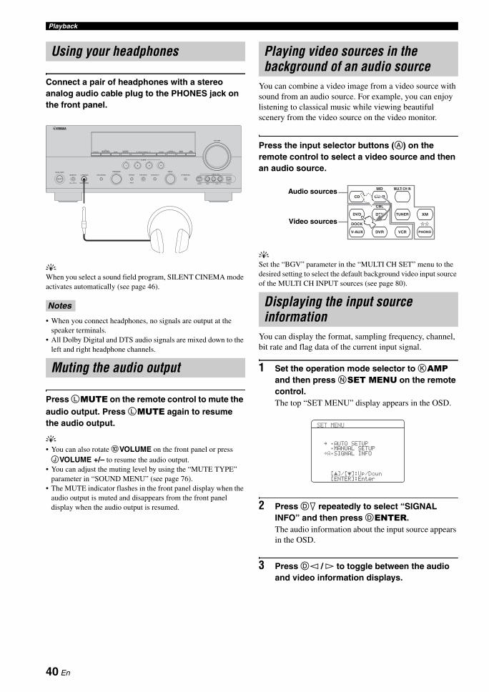
Playback
Connect a pair of headphones with a stereo analog audio cable plug to the PHONES jack on the front panel.
yWhen you select a sound field program, SILENT CINEMA mode activates automatically (see page 46).
• When you connect headphones, no signals are output at the speaker terminals.
• All Dolby Digital and DTS audio signals are mixed down to the left and right headphone channels.
Press LMUTE on the remote control to mute the audio output. Press LMUTE again to resume the audio output.
y• You can also rotate 0VOLUME on the front panel or press JVOLUME +/– to resume the audio output.
• You can adjust the muting level by using the “MUTE TYPE” parameter in “SOUND MENU” (see page 76).
• The MUTE indicator flashes in the front panel display when the audio output is muted and disappears from the front panel display when the audio output is resumed.
You can combine a video image from a video source with sound from an audio source. For example, you can enjoy listening to classical music while viewing beautiful scenery from the video source on the video monitor.
Press the input selector buttons (A) on the remote control to select a video source and then an audio source.
ySet the “BGV” parameter in the “MULTI CH SET” menu to the desired setting to select the default background video input source of the MULTI CH INPUT sources (see page 80).
You can display the format, sampling frequency, channel, bit rate and flag data of the current input signal.
1 Set the operation mode selector to KAMP and then press NSET MENU on the remote control.The top “SET MENU” display appears in the OSD.
2 Press Dn repeatedly to select “SIGNAL INFO” and then press DENTER.The audio information about the input source appears in the OSD.
3 Press Dl / h to toggle between the audio and video information displays.
Using your headphones
Notes
Muting the audio output
ON/OFF
MAIN ZONE
MASTER PHONES TONE CONTROL
PROGRAM
SPEAKERS PRESET/TUNINGSEARCH MODE
FM/AM A/B/C/D/ECATEGORY
PRESET/TUNING/CH MEMORY TUNING ON/OFF CONTROLAUTO/MAN'LDISPLAY ZONE 2 ZONE
EDIT
STRAIGHT
1 2 3 4
PURE DIRECT
SCENE
AUDIO SELECT
INPUT
VIDEO AUX
VOLUME
OPTIMIZER MIC
S VIDEO VIDEO AUDIO OPTICALL REFFECTSILENT CINEMAON OFF
Playing video sources in the background of an audio source
Displaying the input source information
CD CD-R
DVD DTV
MD MULTI CH IN
CBL
TUNER
V-AUX
DOCK
DVR VCR
XM
PHONO
Audio sources
Video sources
SET MENU
. ;AUTO SETUP;MANUAL SETUP
.A;SIGNAL INFO
[ ]/[ ]:Up/Down[ENTER]:Enter
p
p
40 En
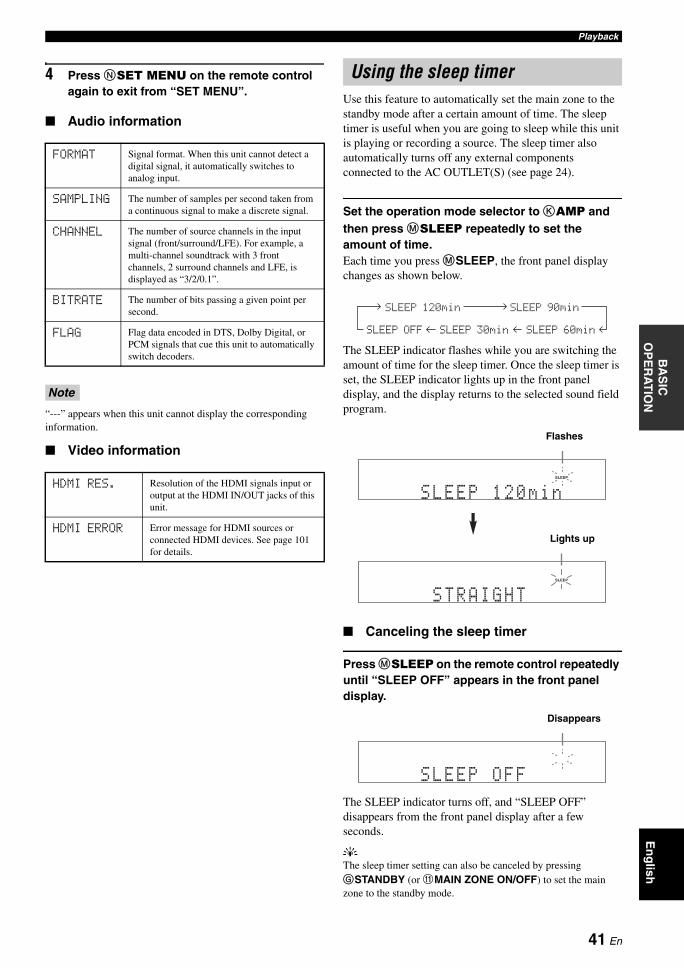
PlaybackB
AS
IC
OP
ER
AT
ION
En
glish
4 Press NSET MENU on the remote control again to exit from “SET MENU”.
Audio information
“---” appears when this unit cannot display the corresponding information.
Video information
Use this feature to automatically set the main zone to the standby mode after a certain amount of time. The sleep timer is useful when you are going to sleep while this unit is playing or recording a source. The sleep timer also automatically turns off any external components connected to the AC OUTLET(S) (see page 24).
Set the operation mode selector to KAMP and then press MSLEEP repeatedly to set the amount of time.Each time you press MSLEEP, the front panel display changes as shown below.
The SLEEP indicator flashes while you are switching the amount of time for the sleep timer. Once the sleep timer is set, the SLEEP indicator lights up in the front panel display, and the display returns to the selected sound field program.
Canceling the sleep timer
Press MSLEEP on the remote control repeatedly until “SLEEP OFF” appears in the front panel display.
The SLEEP indicator turns off, and “SLEEP OFF” disappears from the front panel display after a few seconds.
yThe sleep timer setting can also be canceled by pressing GSTANDBY (or AMAIN ZONE ON/OFF) to set the main zone to the standby mode.
FORMAT Signal format. When this unit cannot detect a digital signal, it automatically switches to analog input.
SAMPLING The number of samples per second taken from a continuous signal to make a discrete signal.
CHANNEL The number of source channels in the input signal (front/surround/LFE). For example, a multi-channel soundtrack with 3 front channels, 2 surround channels and LFE, is displayed as “3/2/0.1”.
BITRATE The number of bits passing a given point per second.
FLAG Flag data encoded in DTS, Dolby Digital, or PCM signals that cue this unit to automatically switch decoders.
Note
HDMI RES. Resolution of the HDMI signals input or output at the HDMI IN/OUT jacks of this unit.
HDMI ERROR Error message for HDMI sources or connected HDMI devices. See page 101 for details.
Using the sleep timer
SLEEP 120min SLEEP 90min
SLEEP 60minSLEEP 30minSLEEP OFF
SLEEP
SLEEP120min
Flashes
SLEEP
STRAIGHT
Lights up
SLEEPOFF
Disappears
41 En
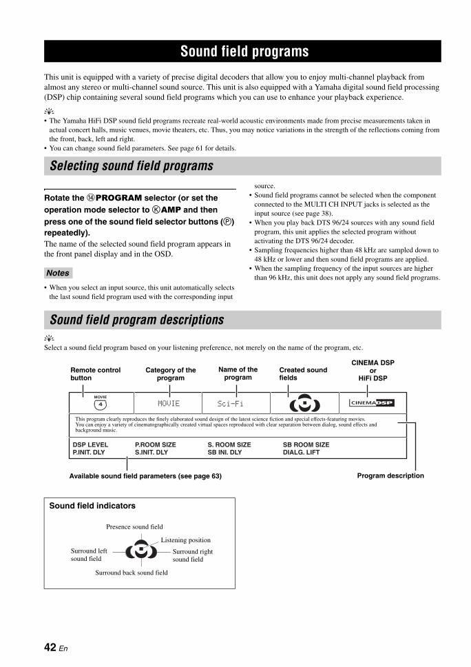
SOUND FIELD PROGRAMS
This unit is equipped with a variety of precise digital decoders that allow you to enjoy multi-channel playback from almost any stereo or multi-channel sound source. This unit is also equipped with a Yamaha digital sound field processing (DSP) chip containing several sound field programs which you can use to enhance your playback experience.
y• The Yamaha HiFi DSP sound field programs recreate real-world acoustic environments made from precise measurements taken in
actual concert halls, music venues, movie theaters, etc. Thus, you may notice variations in the strength of the reflections coming from the front, back, left and right.
• You can change sound field parameters. See page 61 for details.
Rotate the DPROGRAM selector (or set the operation mode selector to KAMP and then press one of the sound field selector buttons (P) repeatedly).The name of the selected sound field program appears in the front panel display and in the OSD.
• When you select an input source, this unit automatically selects the last sound field program used with the corresponding input
source.• Sound field programs cannot be selected when the component
connected to the MULTI CH INPUT jacks is selected as the input source (see page 38).
• When you play back DTS 96/24 sources with any sound field program, this unit applies the selected program without activating the DTS 96/24 decoder.
• Sampling frequencies higher than 48 kHz are sampled down to 48 kHz or lower and then sound field programs are applied.
• When the sampling frequency of the input sources are higher than 96 kHz, this unit does not apply any sound field programs.
ySelect a sound field program based on your listening preference, not merely on the name of the program, etc.
Sound field programs
Selecting sound field programs
Notes
Sound field program descriptions
Sound field indicators
DIALG. LIFTSB ROOM SIZES. ROOM SIZE
SB INI. DLYS.INIT. DLYP.ROOM SIZE
Sci-FiMOVIE
P.INIT. DLYDSP LEVEL
4
MOVIE
This program clearly reproduces the finely elaborated sound design of the latest science fiction and special effects-featuring movies. You can enjoy a variety of cinematographically created virtual spaces reproduced with clear separation between dialog, sound effects and background music.
Available sound field parameters (see page 63) Program description
Remote control button
Name of the program
Created sound fields
Category of the program
CINEMA DSP or
HiFi DSP
Presence sound field
Listening position
Surround left sound field
Surround right sound field
Surround back sound field
42 En
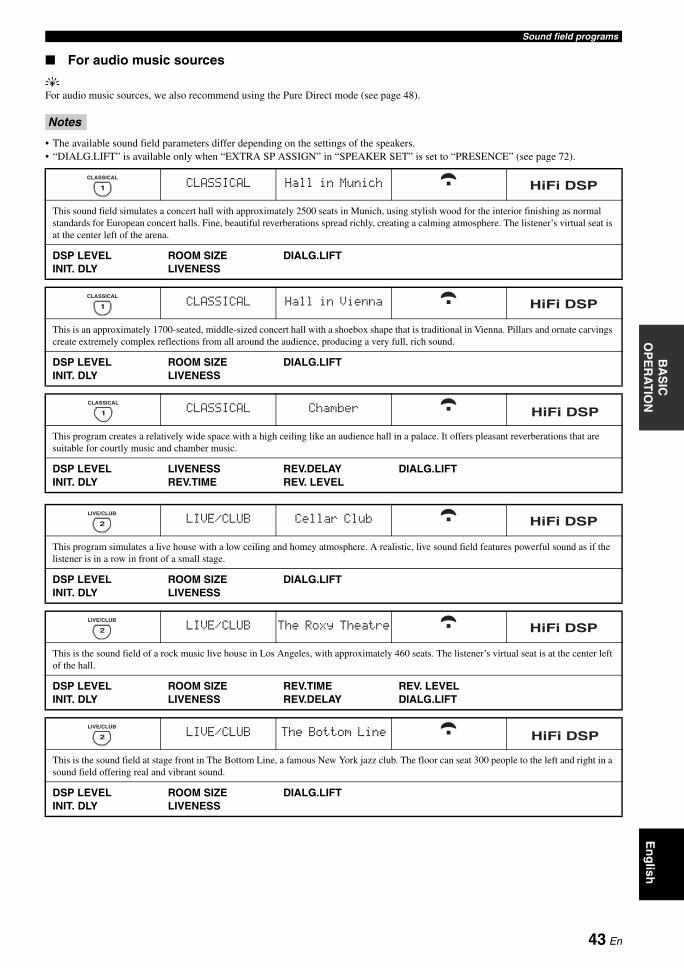
Sound field programsB
AS
IC
OP
ER
AT
ION
En
glish
For audio music sources
yFor audio music sources, we also recommend using the Pure Direct mode (see page 48).
• The available sound field parameters differ depending on the settings of the speakers.• “DIALG.LIFT” is available only when “EXTRA SP ASSIGN” in “SPEAKER SET” is set to “PRESENCE” (see page 72).
Notes
CLASSICAL Hall in Munich
This sound field simulates a concert hall with approximately 2500 seats in Munich, using stylish wood for the interior finishing as normal standards for European concert halls. Fine, beautiful reverberations spread richly, creating a calming atmosphere. The listener’s virtual seat is at the center left of the arena.
DSP LEVELINIT. DLY
ROOM SIZELIVENESS
DIALG.LIFT
CLASSICAL Hall in Vienna
This is an approximately 1700-seated, middle-sized concert hall with a shoebox shape that is traditional in Vienna. Pillars and ornate carvings create extremely complex reflections from all around the audience, producing a very full, rich sound.
DSP LEVELINIT. DLY
ROOM SIZELIVENESS
DIALG.LIFT
CLASSICAL Chamber
This program creates a relatively wide space with a high ceiling like an audience hall in a palace. It offers pleasant reverberations that are suitable for courtly music and chamber music.
DSP LEVELINIT. DLY
LIVENESSREV.TIME
REV.DELAYREV. LEVEL
DIALG.LIFT
LIVE/CLUB Cellar Club
This program simulates a live house with a low ceiling and homey atmosphere. A realistic, live sound field features powerful sound as if the listener is in a row in front of a small stage.
DSP LEVELINIT. DLY
ROOM SIZELIVENESS
DIALG.LIFT
LIVE/CLUB The Roxy Theatre
This is the sound field of a rock music live house in Los Angeles, with approximately 460 seats. The listener’s virtual seat is at the center left of the hall.
DSP LEVELINIT. DLY
ROOM SIZELIVENESS
REV.TIMEREV.DELAY
REV. LEVELDIALG.LIFT
LIVE/CLUB The Bottom Line
This is the sound field at stage front in The Bottom Line, a famous New York jazz club. The floor can seat 300 people to the left and right in a sound field offering real and vibrant sound.
DSP LEVELINIT. DLY
ROOM SIZELIVENESS
DIALG.LIFT
3
ENTERTAIN
1
CLASSICAL
HiFi DSP
3
ENTERTAIN
1
CLASSICAL
HiFi DSP
1
CLASSICAL
HiFi DSP
2
LIVE/CLUB
HiFi DSP
2
LIVE/CLUB
HiFi DSP
2
LIVE/CLUB
HiFi DSP
43 En
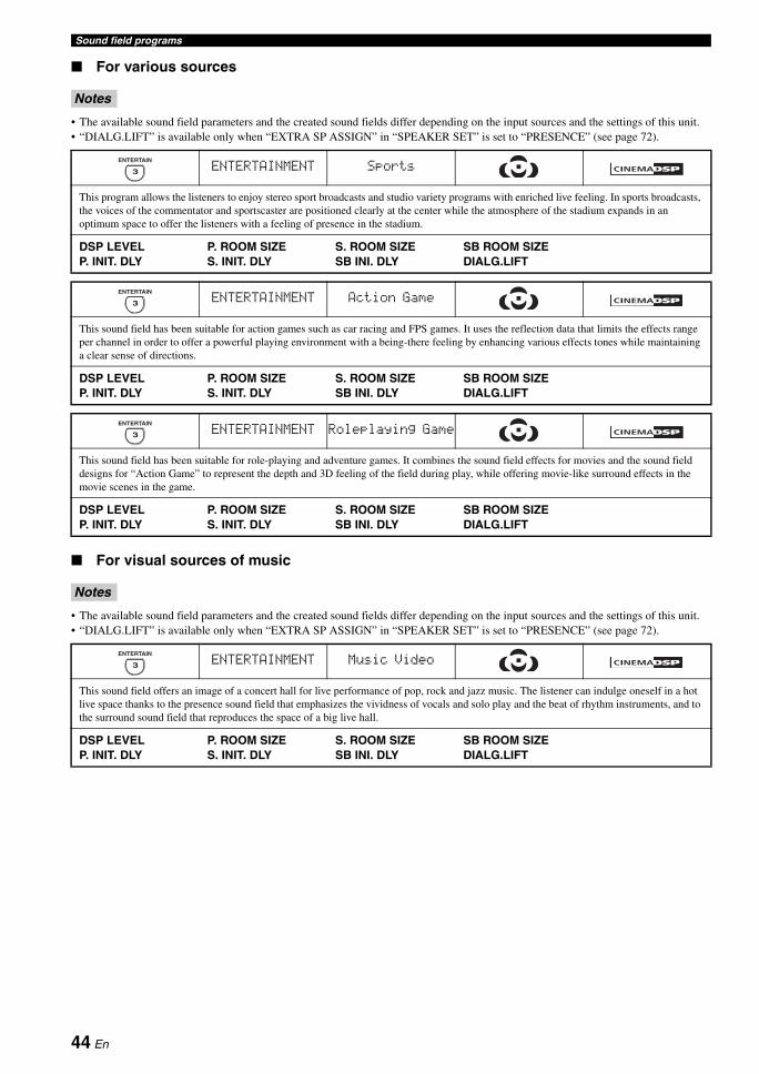
Sound field programs
For various sources
• The available sound field parameters and the created sound fields differ depending on the input sources and the settings of this unit.• “DIALG.LIFT” is available only when “EXTRA SP ASSIGN” in “SPEAKER SET” is set to “PRESENCE” (see page 72).
For visual sources of music
• The available sound field parameters and the created sound fields differ depending on the input sources and the settings of this unit.• “DIALG.LIFT” is available only when “EXTRA SP ASSIGN” in “SPEAKER SET” is set to “PRESENCE” (see page 72).
Notes
ENTERTAINMENT Sports
This program allows the listeners to enjoy stereo sport broadcasts and studio variety programs with enriched live feeling. In sports broadcasts, the voices of the commentator and sportscaster are positioned clearly at the center while the atmosphere of the stadium expands in an optimum space to offer the listeners with a feeling of presence in the stadium.
DSP LEVELP. INIT. DLY
P. ROOM SIZES. INIT. DLY
S. ROOM SIZESB INI. DLY
SB ROOM SIZEDIALG.LIFT
ENTERTAINMENT Action Game
This sound field has been suitable for action games such as car racing and FPS games. It uses the reflection data that limits the effects range per channel in order to offer a powerful playing environment with a being-there feeling by enhancing various effects tones while maintaining a clear sense of directions.
DSP LEVELP. INIT. DLY
P. ROOM SIZES. INIT. DLY
S. ROOM SIZESB INI. DLY
SB ROOM SIZEDIALG.LIFT
ENTERTAINMENT Roleplaying Game
This sound field has been suitable for role-playing and adventure games. It combines the sound field effects for movies and the sound field designs for “Action Game” to represent the depth and 3D feeling of the field during play, while offering movie-like surround effects in the movie scenes in the game.
DSP LEVELP. INIT. DLY
P. ROOM SIZES. INIT. DLY
S. ROOM SIZESB INI. DLY
SB ROOM SIZEDIALG.LIFT
Notes
ENTERTAINMENT Music Video
This sound field offers an image of a concert hall for live performance of pop, rock and jazz music. The listener can indulge oneself in a hot live space thanks to the presence sound field that emphasizes the vividness of vocals and solo play and the beat of rhythm instruments, and to the surround sound field that reproduces the space of a big live hall.
DSP LEVELP. INIT. DLY
P. ROOM SIZES. INIT. DLY
S. ROOM SIZESB INI. DLY
SB ROOM SIZEDIALG.LIFT
3
ENTERTAIN
3
ENTERTAIN
3
ENTERTAIN
2
LIVE/CLUB
3
ENTERTAIN
HiFi DSP
44 En
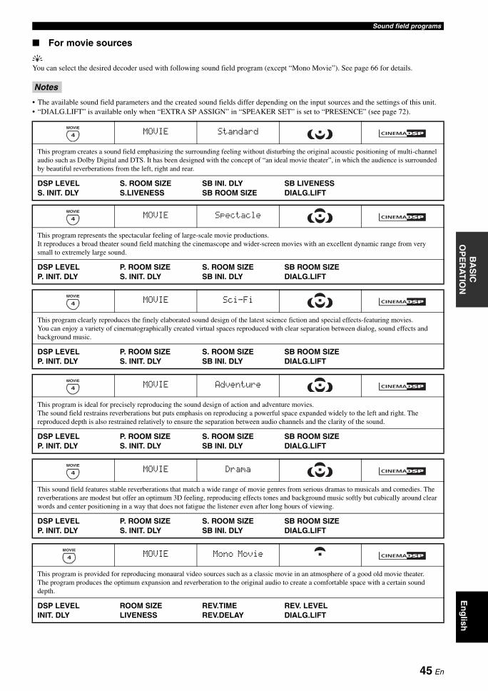
Sound field programsB
AS
IC
OP
ER
AT
ION
En
glish
For movie sources
yYou can select the desired decoder used with following sound field program (except “Mono Movie”). See page 66 for details.
• The available sound field parameters and the created sound fields differ depending on the input sources and the settings of this unit.• “DIALG.LIFT” is available only when “EXTRA SP ASSIGN” in “SPEAKER SET” is set to “PRESENCE” (see page 72).
Notes
MOVIE Standard
This program creates a sound field emphasizing the surrounding feeling without disturbing the original acoustic positioning of multi-channel audio such as Dolby Digital and DTS. It has been designed with the concept of “an ideal movie theater”, in which the audience is surrounded by beautiful reverberations from the left, right and rear.
DSP LEVELS. INIT. DLY
S. ROOM SIZES.LIVENESS
SB INI. DLYSB ROOM SIZE
SB LIVENESSDIALG.LIFT
MOVIE Spectacle
This program represents the spectacular feeling of large-scale movie productions. It reproduces a broad theater sound field matching the cinemascope and wider-screen movies with an excellent dynamic range from very small to extremely large sound.
DSP LEVELP. INIT. DLY
P. ROOM SIZES. INIT. DLY
S. ROOM SIZESB INI. DLY
SB ROOM SIZEDIALG.LIFT
4
MOVIE
4
MOVIE
MOVIE Sci-Fi
This program clearly reproduces the finely elaborated sound design of the latest science fiction and special effects-featuring movies. You can enjoy a variety of cinematographically created virtual spaces reproduced with clear separation between dialog, sound effects and background music.
DSP LEVELP. INIT. DLY
P. ROOM SIZES. INIT. DLY
S. ROOM SIZESB INI. DLY
SB ROOM SIZEDIALG.LIFT
4
MOVIE
MOVIE Adventure
This program is ideal for precisely reproducing the sound design of action and adventure movies.The sound field restrains reverberations but puts emphasis on reproducing a powerful space expanded widely to the left and right. The reproduced depth is also restrained relatively to ensure the separation between audio channels and the clarity of the sound.
DSP LEVELP. INIT. DLY
P. ROOM SIZES. INIT. DLY
S. ROOM SIZESB INI. DLY
SB ROOM SIZEDIALG.LIFT
4
MOVIE
MOVIE Drama
This sound field features stable reverberations that match a wide range of movie genres from serious dramas to musicals and comedies. The reverberations are modest but offer an optimum 3D feeling, reproducing effects tones and background music softly but cubically around clear words and center positioning in a way that does not fatigue the listener even after long hours of viewing.
DSP LEVELP. INIT. DLY
P. ROOM SIZES. INIT. DLY
S. ROOM SIZESB INI. DLY
SB ROOM SIZEDIALG.LIFT
4
MOVIE
MOVIE Mono Movie
This program is provided for reproducing monaural video sources such as a classic movie in an atmosphere of a good old movie theater.The program produces the optimum expansion and reverberation to the original audio to create a comfortable space with a certain sound depth.
DSP LEVELINIT. DLY
ROOM SIZELIVENESS
REV.TIMEREV.DELAY
REV. LEVELDIALG.LIFT
4
MOVIE
45 En
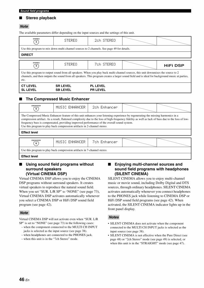
Sound field programs
Stereo playback
The available parameters differ depending on the input sources and the settings of this unit.
The Compressed Music Enhancer
Using sound field programs without surround speakers (Virtual CINEMA DSP)
Virtual CINEMA DSP allows you to enjoy the CINEMA DSP programs without surround speakers. It creates virtual speakers to reproduce the natural sound field.When you set “SUR. L/R SP” to “NONE” (see page 73), Virtual CINEMA DSP activates automatically whenever you select a CINEMA DSP or HiFi DSP sound field program (see page 42).
Virtual CINEMA DSP will not activate even when “SUR. L/R SP” is set to “NONE” (see page 73) in the following cases:
– when the component connected to the MULTI CH INPUT jacks is selected as the input source (see page 38).
– when headphones are connected to the PHONES jack.– when this unit is in the “7ch Stereo” mode.
Enjoying multi-channel sources and sound field programs with headphones (SILENT CINEMA)
SILENT CINEMA allows you to enjoy multi-channel music or movie sound, including Dolby Digital and DTS sources, through ordinary headphones. SILENT CINEMA activates automatically whenever you connect headphones to the PHONES jack while listening to CINEMA DSP or HiFi DSP sound field programs (see page 42). When activated, the SILENT CINEMA indicator lights up in the front panel display.
• SILENT CINEMA does not activate when the component connected to the MULTI CH INPUT jacks is selected as the input source (see page 38).
• SILENT CINEMA is not effective when the Pure Direct (see page 48) or “2ch Stereo” mode (see page 49) is selected, or when this unit is in the “STRAIGHT” mode (see page 47).
Note
STEREO 2ch STEREO
Use this program to mix down multi-channel sources to 2 channels. See page 49 for details.
DIRECT
5
STEREO
STEREO 7ch STEREO
Use this program to output sound from all speakers. When you play back multi-channel sources, this unit downmixes the source to 2 channels, and then outputs the sound from all speakers. This program creates a larger sound field and is ideal for background music at parties, etc.
CT LEVELSL LEVEL
SR LEVELSB LEVEL
PL LEVELPR LEVEL
MUSIC ENHANCER 2ch Enhancer
The Compressed Music Enhancer feature of this unit enhances your listening experience by regenerating the missing harmonics in a compression artifact. As a result, flattened complexity due to the loss of high-frequency fidelity as well as lack of bass due to the loss of low-frequency bass is compensated, providing improved performance of the overall sound system.Use this program to play back compression artifacts in 2-channel stereo.
Effect level
5
STEREO
HiFi DSP
6
ENHANCER
MUSIC ENHANCER 7ch Enhancer
Use this program to play back compression artifacts in 7-channel stereo.
Effect level
6
ENHANCER
NoteNotes
46 En
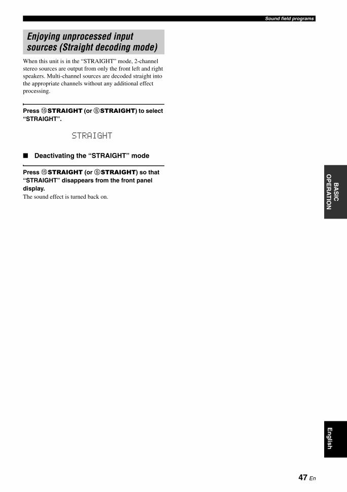
Sound field programsB
AS
IC
OP
ER
AT
ION
En
glish
When this unit is in the “STRAIGHT” mode, 2-channel stereo sources are output from only the front left and right speakers. Multi-channel sources are decoded straight into the appropriate channels without any additional effect processing.
Press ESTRAIGHT (or SSTRAIGHT) to select “STRAIGHT”.
Deactivating the “STRAIGHT” mode
Press ESTRAIGHT (or SSTRAIGHT) so that “STRAIGHT” disappears from the front panel display.The sound effect is turned back on.
Enjoying unprocessed input sources (Straight decoding mode)
STRAIGHT
47 En
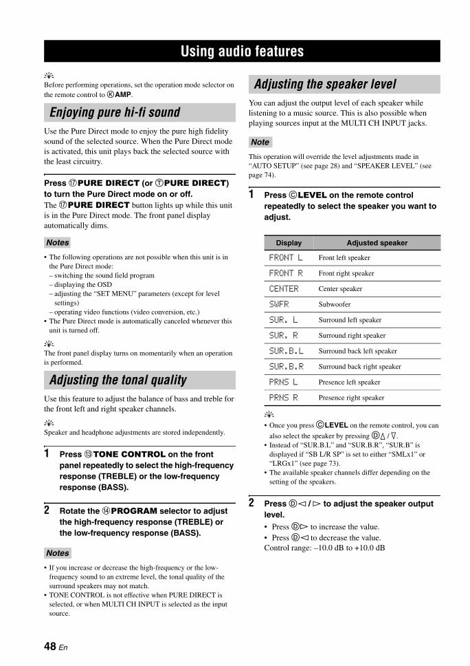
USING AUDIO FEATURES
yBefore performing operations, set the operation mode selector on the remote control to KAMP.
Use the Pure Direct mode to enjoy the pure high fidelity sound of the selected source. When the Pure Direct mode is activated, this unit plays back the selected source with the least circuitry.
Press GPURE DIRECT (or TPURE DIRECT) to turn the Pure Direct mode on or off.The GPURE DIRECT button lights up while this unit is in the Pure Direct mode. The front panel display automatically dims.
• The following operations are not possible when this unit is in the Pure Direct mode:– switching the sound field program– displaying the OSD– adjusting the “SET MENU” parameters (except for level
settings)– operating video functions (video conversion, etc.)
• The Pure Direct mode is automatically canceled whenever this unit is turned off.
yThe front panel display turns on momentarily when an operation is performed.
Use this feature to adjust the balance of bass and treble for the front left and right speaker channels.
ySpeaker and headphone adjustments are stored independently.
1 Press CTONE CONTROL on the front panel repeatedly to select the high-frequency response (TREBLE) or the low-frequency response (BASS).
2 Rotate the DPROGRAM selector to adjust the high-frequency response (TREBLE) or the low-frequency response (BASS).
• If you increase or decrease the high-frequency or the low-frequency sound to an extreme level, the tonal quality of the surround speakers may not match.
• TONE CONTROL is not effective when PURE DIRECT is selected, or when MULTI CH INPUT is selected as the input source.
You can adjust the output level of each speaker while listening to a music source. This is also possible when playing sources input at the MULTI CH INPUT jacks.
This operation will override the level adjustments made in “AUTO SETUP” (see page 28) and “SPEAKER LEVEL” (see page 74).
1 Press CLEVEL on the remote control repeatedly to select the speaker you want to adjust.
y• Once you press CLEVEL on the remote control, you can
also select the speaker by pressing Dk / n.• Instead of “SUR.B.L” and “SUR.B.R”, “SUR.B” is
displayed if “SB L/R SP” is set to either “SMLx1” or “LRGx1” (see page 73).
• The available speaker channels differ depending on the setting of the speakers.
2 Press Dl / h to adjust the speaker output level.• Press Dh to increase the value.• Press Dl to decrease the value.Control range: –10.0 dB to +10.0 dB
Using audio features
Enjoying pure hi-fi sound
Notes
Adjusting the tonal quality
Notes
Adjusting the speaker level
Note
Display Adjusted speaker
FRONT L Front left speaker
FRONT R Front right speaker
CENTER Center speaker
SWFR Subwoofer
SUR. L Surround left speaker
SUR. R Surround right speaker
SUR.B.L Surround back left speaker
SUR.B.R Surround back right speaker
PRNS L Presence left speaker
PRNS R Presence right speaker
48 En
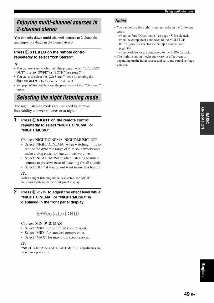
Using audio featuresB
AS
IC
OP
ER
AT
ION
En
glish
You can mix down multi-channel sources to 2 channels and enjoy playback in 2-channel stereo.
Press PSTEREO on the remote control repeatedly to select “2ch Stereo”.
y• You can use a subwoofer with this program when “LFE/BASS
OUT” is set to “SWFR” or “BOTH” (see page 74).• You can also select the “2ch Stereo” mode by rotating the DPROGRAM selector on the front panel.
• See page 66 for details about the parameters of the “2ch Stereo” mode.
The night listening modes are designed to improve listenability at lower volumes or at night.
1 Press RNIGHT on the remote control repeatedly to select “NIGHT:CINEMA” or “NIGHT:MUSIC”.
Choices: NIGHT:CINEMA, NIGHT:MUSIC, OFF• Select “NIGHT:CINEMA” when watching films to
reduce the dynamic range of film soundtracks and make dialog easier to hear at lower volumes.
• Select “NIGHT:MUSIC” when listening to music sources to preserve ease-of-listening for all sounds.
• Select “OFF” if you do not want to use this feature.
yWhen a night listening mode is selected, the NIGHT indicator lights up in the front panel display.
2 Press Dl / h to adjust the effect level while “NIGHT:CINEMA” or “NIGHT:MUSIC” is displayed in the front panel display.
Choices: MIN, MID, MAX• Select “MIN” for minimum compression.• Select “MID” for standard compression.• Select “MAX” for maximum compression.
y“NIGHT:CINEMA” and “NIGHT:MUSIC” adjustments are stored independently.
• You cannot use the night listening modes in the following cases:–when the Pure Direct mode (see page 48) is selected.–when the component connected to the MULTI CH
INPUT jacks is selected as the input source (see page 38).
–when headphones are connected to the PHONES jack.• The night listening modes may vary in effectiveness
depending on the input source and surround sound settings you use.
Enjoying multi-channel sources in 2-channel stereo
Selecting the night listening mode
Effect.Lvl:MID
Notes
49 En
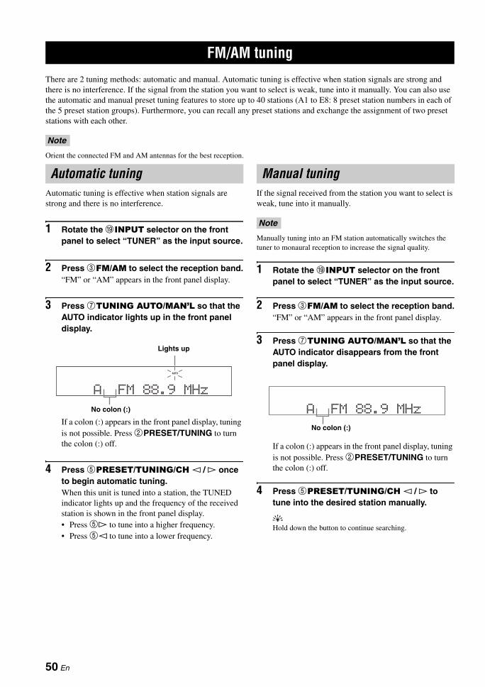
FM/AM TUNING
There are 2 tuning methods: automatic and manual. Automatic tuning is effective when station signals are strong and there is no interference. If the signal from the station you want to select is weak, tune into it manually. You can also use the automatic and manual preset tuning features to store up to 40 stations (A1 to E8: 8 preset station numbers in each of the 5 preset station groups). Furthermore, you can recall any preset stations and exchange the assignment of two preset stations with each other.
Orient the connected FM and AM antennas for the best reception.
Automatic tuning is effective when station signals are strong and there is no interference.
1 Rotate the IINPUT selector on the front panel to select “TUNER” as the input source.
2 Press 3FM/AM to select the reception band.“FM” or “AM” appears in the front panel display.
3 Press 7TUNING AUTO/MAN’L so that the AUTO indicator lights up in the front panel display.
If a colon (:) appears in the front panel display, tuning is not possible. Press 2PRESET/TUNING to turn the colon (:) off.
4 Press 5PRESET/TUNING/CH l / h once to begin automatic tuning.When this unit is tuned into a station, the TUNED indicator lights up and the frequency of the received station is shown in the front panel display.• Press 5h to tune into a higher frequency.• Press 5l to tune into a lower frequency.
If the signal received from the station you want to select is weak, tune into it manually.
Manually tuning into an FM station automatically switches the tuner to monaural reception to increase the signal quality.
1 Rotate the IINPUT selector on the front panel to select “TUNER” as the input source.
2 Press 3FM/AM to select the reception band.“FM” or “AM” appears in the front panel display.
3 Press 7TUNING AUTO/MAN’L so that the AUTO indicator disappears from the front panel display.
If a colon (:) appears in the front panel display, tuning is not possible. Press 2PRESET/TUNING to turn the colon (:) off.
4 Press 5PRESET/TUNING/CH l / h to tune into the desired station manually.
yHold down the button to continue searching.
FM/AM tuning
Note
Automatic tuning
AFM88.9MHz
AUTO
Lights up
No colon (:)
Manual tuning
Note
AFM88.9MHz
No colon (:)
50 En
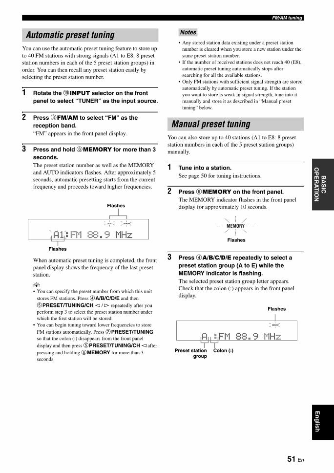
FM/AM tuningB
AS
IC
OP
ER
AT
ION
En
glish
You can use the automatic preset tuning feature to store up to 40 FM stations with strong signals (A1 to E8: 8 preset station numbers in each of the 5 preset station groups) in order. You can then recall any preset station easily by selecting the preset station number.
1 Rotate the IINPUT selector on the front panel to select “TUNER” as the input source.
2 Press 3FM/AM to select “FM” as the reception band.“FM” appears in the front panel display.
3 Press and hold 6MEMORY for more than 3 seconds.The preset station number as well as the MEMORY and AUTO indicators flashes. After approximately 5 seconds, automatic presetting starts from the current frequency and proceeds toward higher frequencies.
When automatic preset tuning is completed, the front panel display shows the frequency of the last preset station.
y• You can specify the preset number from which this unit
stores FM stations. Press 4A/B/C/D/E and then 5PRESET/TUNING/CH l / h repeatedly after you perform step 3 to select the preset station number under which the first station will be stored.
• You can begin tuning toward lower frequencies to store FM stations automatically. Press 2PRESET/TUNING so that the colon (:) disappears from the front panel display and then press 5PRESET/TUNING/CH l after pressing and holding 6MEMORY for more than 3 seconds.
• Any stored station data existing under a preset station number is cleared when you store a new station under the same preset station number.
• If the number of received stations does not reach 40 (E8), automatic preset tuning automatically stops after searching for all the available stations.
• Only FM stations with sufficient signal strength are stored automatically by automatic preset tuning. If the station you want to store is weak in signal strength, tune into it manually and store it as described in “Manual preset tuning” below.
You can also store up to 40 stations (A1 to E8: 8 preset station numbers in each of the 5 preset station groups) manually.
1 Tune into a station.See page 50 for tuning instructions.
2 Press 6MEMORY on the front panel.The MEMORY indicator flashes in the front panel display for approximately 10 seconds.
3 Press 4A/B/C/D/E repeatedly to select a preset station group (A to E) while the MEMORY indicator is flashing.The selected preset station group letter appears. Check that the colon (:) appears in the front panel display.
Automatic preset tuning
A1:FM88.9MHz
AUTO MEMORY
Flashes
Flashes
Notes
Manual preset tuning
MEMORY
Flashes
A:FM88.9MHz
MEMORY
Preset stationgroup
Flashes
Colon (:)
51 En
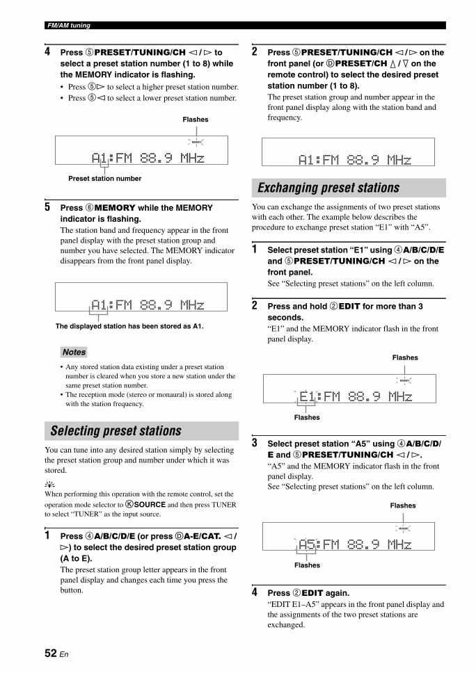
FM/AM tuning
4 Press 5PRESET/TUNING/CH l / h to select a preset station number (1 to 8) while the MEMORY indicator is flashing.• Press 5h to select a higher preset station number.• Press 5l to select a lower preset station number.
5 Press 6MEMORY while the MEMORY indicator is flashing.The station band and frequency appear in the front panel display with the preset station group and number you have selected. The MEMORY indicator disappears from the front panel display.
• Any stored station data existing under a preset station number is cleared when you store a new station under the same preset station number.
• The reception mode (stereo or monaural) is stored along with the station frequency.
You can tune into any desired station simply by selecting the preset station group and number under which it was stored.
yWhen performing this operation with the remote control, set the
operation mode selector to KSOURCE and then press TUNER to select “TUNER” as the input source.
1 Press 4A/B/C/D/E (or press DA-E/CAT. l / h) to select the desired preset station group (A to E).The preset station group letter appears in the front panel display and changes each time you press the button.
2 Press 5PRESET/TUNING/CH l / h on the front panel (or DPRESET/CH k / n on the remote control) to select the desired preset station number (1 to 8).The preset station group and number appear in the front panel display along with the station band and frequency.
You can exchange the assignments of two preset stations with each other. The example below describes the procedure to exchange preset station “E1” with “A5”.
1 Select preset station “E1” using 4A/B/C/D/E and 5PRESET/TUNING/CH l / h on the front panel.See “Selecting preset stations” on the left column.
2 Press and hold 2EDIT for more than 3 seconds.“E1” and the MEMORY indicator flash in the front panel display.
3 Select preset station “A5” using 4A/B/C/D/E and 5PRESET/TUNING/CH l / h.“A5” and the MEMORY indicator flash in the front panel display.See “Selecting preset stations” on the left column.
4 Press 2EDIT again.“EDIT E1–A5” appears in the front panel display and the assignments of the two preset stations are exchanged.
Notes
Selecting preset stations
A1:FM88.9MHz
MEMORY
Preset station number
Flashes
A1:FM88.9MHz
The displayed station has been stored as A1.
Exchanging preset stations
A1:FM88.9MHz
E1:FM88.9MHz
MEMORY
Flashes
Flashes
A5:FM88.9MHz
MEMORY
Flashes
Flashes
52 En
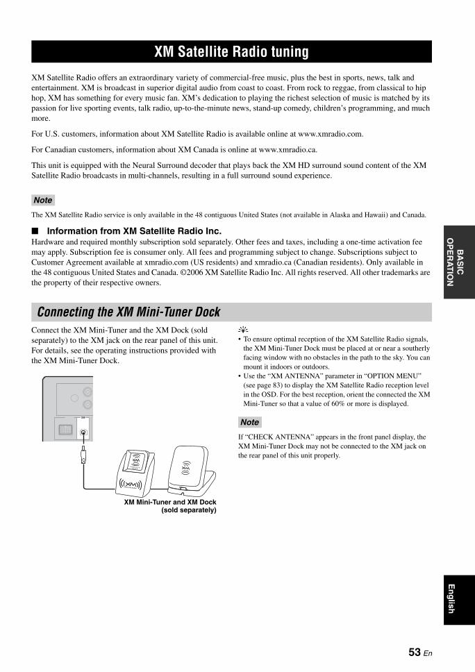
XM SATELLITE RADIO TUNINGB
AS
IC
OP
ER
AT
ION
En
glish
XM Satellite Radio offers an extraordinary variety of commercial-free music, plus the best in sports, news, talk and entertainment. XM is broadcast in superior digital audio from coast to coast. From rock to reggae, from classical to hip hop, XM has something for every music fan. XM’s dedication to playing the richest selection of music is matched by its passion for live sporting events, talk radio, up-to-the-minute news, stand-up comedy, children’s programming, and much more.
For U.S. customers, information about XM Satellite Radio is available online at www.xmradio.com.
For Canadian customers, information about XM Canada is online at www.xmradio.ca.
This unit is equipped with the Neural Surround decoder that plays back the XM HD surround sound content of the XM Satellite Radio broadcasts in multi-channels, resulting in a full surround sound experience.
The XM Satellite Radio service is only available in the 48 contiguous United States (not available in Alaska and Hawaii) and Canada.
Information from XM Satellite Radio Inc.Hardware and required monthly subscription sold separately. Other fees and taxes, including a one-time activation fee may apply. Subscription fee is consumer only. All fees and programming subject to change. Subscriptions subject to Customer Agreement available at xmradio.com (US residents) and xmradio.ca (Canadian residents). Only available in the 48 contiguous United States and Canada. ©2006 XM Satellite Radio Inc. All rights reserved. All other trademarks are the property of their respective owners.
Connect the XM Mini-Tuner and the XM Dock (sold separately) to the XM jack on the rear panel of this unit. For details, see the operating instructions provided with the XM Mini-Tuner Dock.
y• To ensure optimal reception of the XM Satellite Radio signals,
the XM Mini-Tuner Dock must be placed at or near a southerly facing window with no obstacles in the path to the sky. You can mount it indoors or outdoors.
• Use the “XM ANTENNA” parameter in “OPTION MENU” (see page 83) to display the XM Satellite Radio reception level in the OSD. For the best reception, orient the connected the XM Mini-Tuner so that a value of 60% or more is displayed.
If “CHECK ANTENNA” appears in the front panel display, the XM Mini-Tuner Dock may not be connected to the XM jack on the rear panel of this unit properly.
XM Satellite Radio tuning
Note
Connecting the XM Mini-Tuner Dock
XM
XM Mini-Tuner and XM Dock(sold separately)
Note
53 En
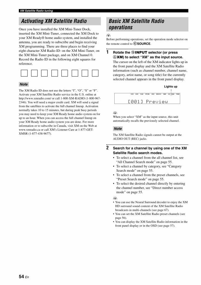
XM Satellite Radio tuning
Once you have installed the XM Mini-Tuner Dock, inserted the XM Mini-Tuner, connected the XM Dock to your XM Ready® home audio system, and installed the antenna, you are ready to subscribe and begin receiving XM programming. There are three places to find your eight character XM Radio ID: on the XM Mini-Tuner, on the XM Mini-Tuner package, and on XM Channel 0. Record the Radio ID in the following eight squares for reference.
The XM Radio ID does not use the letters “I”, “O”, “S” or “F”. Activate your XM Satellite Radio service in the U.S. online at http://www.xmradio.com/ or call 1-800-XM-RADIO (1-800-967-2346). You will need a major credit card. XM will send a signal from the satellites to activate the full channel lineup. Activation normally takes 10 to 15 minutes, but during peak busy periods you may need to keep your XM Ready home audio system on for up to an hour. When you can access the full channel lineup on your XM Ready home audio system you are done. For more information or to subscribe in Canada, visit XM on the Web at www.xmradio.ca or call XM’s Listener Care at 1-877-GET-XMSR (1-877-438-9677).
yBefore performing operations, set the operation mode selector on
the remote control to KSOURCE.
1 Rotate the IINPUT selector (or press AXM) to select “XM” as the input source.The cursor on the left of the XM indicator lights up in the front panel display and the XM Satellite Radio information (such as channel number, channel name, category, artist name, or song title) for the currently selected channel appears in the front panel display.
yWhen you select “XM” as the input source, this unit automatically recalls the previously selected channel.
The XM Satellite Radio signals cannot be output at the AUDIO OUT (REC) jacks.
2 Search for a channel by using one of the XM Satellite Radio search modes.• To select a channel from the all channel list, see
“All Channel Search mode” on page 55.• To select a channel by category, see “Category
Search mode” on page 55.• To select a channel from the preset channels, see
“Preset Search mode” on page 55.• To select the desired channel directly by entering
the channel number, see “Direct number access mode” on page 55.
y• You can use the Neural Surround decoder to enjoy the XM
HD surround sound content of the XM Satellite Radio broadcasts in multi-channels (see page 67).
• You can set the XM Satellite Radio preset channels (see page 56).
• You can display the XM Satellite Radio information in the front panel display or in the OSD (see page 57).
Activating XM Satellite Radio
Note
Basic XM Satellite Radio operations
Note
[001] Preview
VCR DVR DVD CD XMV-AUX DTV/CBL MD/CD-R TUNER PHONO
Lights up
54 En
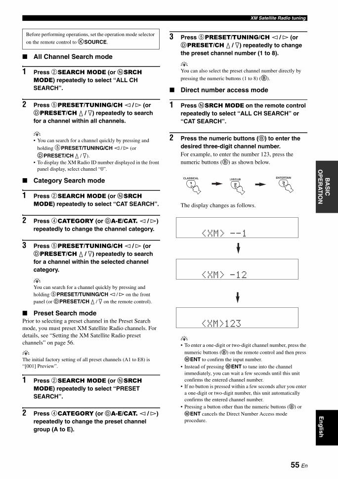
XM Satellite Radio tuningB
AS
IC
OP
ER
AT
ION
En
glish
All Channel Search mode
1 Press 2SEARCH MODE (or NSRCH MODE) repeatedly to select “ALL CH SEARCH”.
2 Press 5PRESET/TUNING/CH l / h (or DPRESET/CH k / n) repeatedly to search for a channel within all channels.
y• You can search for a channel quickly by pressing and
holding 5PRESET/TUNING/CH l / h (or DPRESET/CH k / n).
• To display the XM Radio ID number displayed in the front panel display, select channel “0”.
Category Search mode
1 Press 2SEARCH MODE (or NSRCH MODE) repeatedly to select “CAT SEARCH”.
2 Press 4CATEGORY (or DA-E/CAT. l / h) repeatedly to change the channel category.
3 Press 5PRESET/TUNING/CH l / h (or DPRESET/CH k / n) repeatedly to search for a channel within the selected channel category.
yYou can search for a channel quickly by pressing and holding 5PRESET/TUNING/CH l / h on the front panel (or DPRESET/CH k / n on the remote control).
Preset Search modePrior to selecting a preset channel in the Preset Search mode, you must preset XM Satellite Radio channels. For details, see “Setting the XM Satellite Radio preset channels” on page 56.
yThe initial factory setting of all preset channels (A1 to E8) is “[001] Preview”.
1 Press 2SEARCH MODE (or NSRCH MODE) repeatedly to select “PRESET SEARCH”.
2 Press 4CATEGORY (or DA-E/CAT. l / h) repeatedly to change the preset channel group (A to E).
3 Press 5PRESET/TUNING/CH l / h (or DPRESET/CH k / n) repeatedly to change the preset channel number (1 to 8).
yYou can also select the preset channel number directly by
pressing the numeric buttons (1 to 8) (B).
Direct number access mode
1 Press NSRCH MODE on the remote control repeatedly to select “ALL CH SEARCH” or “CAT SEARCH”.
2 Press the numeric buttons (B) to enter the desired three-digit channel number.For example, to enter the number 123, press the numeric buttons (B) as shown below.
The display changes as follows.
y• To enter a one-digit or two-digit channel number, press the
numeric buttons (B) on the remote control and then press MENT to confirm the input number.
• Instead of pressing MENT to tune into the channel immediately, you can wait a few seconds until this unit confirms the entered channel number.
• If no button is pressed within a few seconds after you enter a one-digit or two-digit number, this unit automatically confirms the entered channel number.
• Pressing a button other than the numeric buttons (B) or MENT cancels the Direct Number Access mode procedure.
Before performing operations, set the operation mode selector
on the remote control to KSOURCE.
1
CLASSICAL
2
LIVE/CLUB3
ENTERTAIN
<XM> --1
<XM> -12
<XM>123
55 En
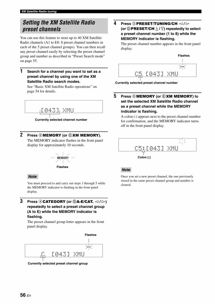
XM Satellite Radio tuning
You can use this feature to store up to 40 XM Satellite Radio channels (A1 to E8: 8 preset channel numbers in each of the 5 preset channel groups). You can then recall any preset channel easily by selecting the preset channel group and number as described in “Preset Search mode” on page 55.
1 Search for a channel you want to set as a preset channel by using one of the XM Satellite Radio search modes.See “Basic XM Satellite Radio operations” on page 54 for details.
2 Press 6MEMORY (or EXM MEMORY).The MEMORY indicator flashes in the front panel display for approximately 10 seconds.
You must proceed to and carry out steps 3 through 5 while the MEMORY indicator is flashing in the front panel display.
3 Press 4CATEGORY (or DA-E/CAT. l / h) repeatedly to select a preset channel group (A to E) while the MEMORY indicator is flashing. The preset channel group letter appears in the front panel display.
4 Press 5PRESET/TUNING/CH l / h (or DPRESET/CH k / n) repeatedly to select a preset channel number (1 to 8) while the MEMORY indicator is flashing.The preset channel number appears in the front panel display.
5 Press 6MEMORY (or EXM MEMORY) to set the selected XM Satellite Radio channel as a preset channel while the MEMORY indicator is flashing.A colon (:) appears next to the preset channel number for confirmation, and the MEMORY indicator turns off in the front panel display.
Once you set a new preset channel, the one previously stored in the same preset channel group and number is cleared.
Setting the XM Satellite Radio preset channels
Note
[043] XMU
Currently selected channel number
MEMORY
Flashes
C [043] XMU
MEMORY
Currently selected preset channel group
Flashes
Note
C5 [043] XMU
MEMORY
Currently selected preset channel number
Flashes
C5:[043] XMU
Colon (:)
56 En
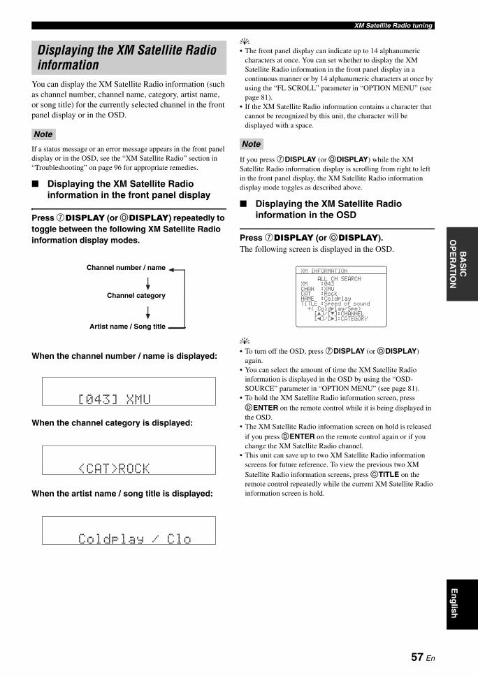
XM Satellite Radio tuningB
AS
IC
OP
ER
AT
ION
En
glish
You can display the XM Satellite Radio information (such as channel number, channel name, category, artist name, or song title) for the currently selected channel in the front panel display or in the OSD.
If a status message or an error message appears in the front panel display or in the OSD, see the “XM Satellite Radio” section in “Troubleshooting” on page 96 for appropriate remedies.
Displaying the XM Satellite Radio information in the front panel display
Press 7DISPLAY (or ODISPLAY) repeatedly to toggle between the following XM Satellite Radio information display modes.
When the channel number / name is displayed:
When the channel category is displayed:
When the artist name / song title is displayed:
y• The front panel display can indicate up to 14 alphanumeric
characters at once. You can set whether to display the XM Satellite Radio information in the front panel display in a continuous manner or by 14 alphanumeric characters at once by using the “FL SCROLL” parameter in “OPTION MENU” (see page 81).
• If the XM Satellite Radio information contains a character that cannot be recognized by this unit, the character will be displayed with a space.
If you press 7DISPLAY (or ODISPLAY) while the XM Satellite Radio information display is scrolling from right to left in the front panel display, the XM Satellite Radio information display mode toggles as described above.
Displaying the XM Satellite Radio information in the OSD
Press 7DISPLAY (or ODISPLAY).The following screen is displayed in the OSD.
y• To turn off the OSD, press 7DISPLAY (or ODISPLAY)
again.• You can select the amount of time the XM Satellite Radio
information is displayed in the OSD by using the “OSD-SOURCE” parameter in “OPTION MENU” (see page 81).
• To hold the XM Satellite Radio information screen, press DENTER on the remote control while it is being displayed in the OSD.
• The XM Satellite Radio information screen on hold is released if you press DENTER on the remote control again or if you change the XM Satellite Radio channel.
• This unit can save up to two XM Satellite Radio information screens for future reference. To view the previous two XM Satellite Radio information screens, press CTITLE on the remote control repeatedly while the current XM Satellite Radio information screen is hold.
Displaying the XM Satellite Radio information
Note
Channel number / name
Channel category
Artist name / Song title
[043] XMU
<CAT>ROCK
Coldplay / Clo
Note
XM INFORMATION
ALL CH SEARCHXM :043CHAN :XMUCAT :RockNAME :ColdplayTITLE:Speed of sound
.( Coldplay/Spe)[ ]/[ ]:CHANNEL[ ]/[ ]:CATEGORY[[
57 En
USING IPOD™
Once you have stationed your iPod in a Yamaha iPod universal dock (such as the YDS-10, sold separately) connected to the DOCK terminal of this unit (see page 23), you can enjoy playback of your iPod using the supplied remote control. You can also use the Compressed Music Enhancer mode of this unit to improve the sound quality of the compression artifacts (such as the MP3 format) stored on your iPod (see page 46).
• Only iPod (Click and Wheel), iPod nano, and iPod mini are supported.• Some features may not be compatible depending on the model or the software version of your iPod.
y• For a complete list of the remote control functions used to control your iPod, see the “iPod” column in “Controlling other
components” on page 86.• For a complete list of status messages that appear in the front panel display and in the OSD, see the “iPod” section in
“Troubleshooting” on page 101.• Once the connection between your iPod and this unit is complete, “iPod connected” appears in the front panel display and the DOCK
indicator lights up in the front panel display.• Only the analog audio and video signals of your iPod are input at the DOCK terminal, and the analog audio signals can be output at the
analog AUDIO OUT (REC) jacks for recording.• Your iPod battery is automatically charged when your iPod is stationed in a Yamaha iPod universal dock connected to the DOCK
terminal of this unit as long as this unit is turned on. You can also select whether this unit charges the battery of the stationed iPod or not when this unit is in the standby mode by selecting the “STANDBY CHARGE” parameter in “OPTION MENU” (see page 83). The DOCK indicator turns on while this unit charges the battery of the connected iPod when this unit is in the standby mode.
You can control your iPod when “V-AUX” is selected as the input source. The operations of your iPod can be done with the aid of the OSD of this unit (menu browse mode) or without it (simple remote mode).
Controlling iPod in the simple remote mode
You can perform the basic operations of your iPod (play, stop, skip, etc.) using the supplied remote control without the aid of the OSD of this unit.
y• You can view the photos or video clips stored on your iPod.• Operations can be also done with the controls on your iPod.
Controlling iPod in the menu browse mode
You can perform the advanced operations of your iPod using the supplied remote control with the aid of the OSD of this unit. You can browse the songs stored on your iPod in the OSD. Further, you can change or adjust settings for your iPod to suit your personal preferences.
y• The name of the song being played also appears in the front
panel display according to the “FL SCROLL” parameter in “OPTION MENU” (see page 81).
• You can select the amount of time the iPod menu and play information is displayed in the OSD by using the “OSD-SOURCE” in “OPTION MENU” (see page 81).
• Operations cannot be done with the controls on your iPod.• The YAMAHA logo appears in the display window of your
iPod.• There are some characters that cannot be displayed in the front
panel display or in the OSD of this unit. Those characters are replaced with underscores “_”.
• The “Settings” parameters can be changed or adjusted only in the OSD. Press ENTER on the remote control to toggle between the “Settings” parameter settings.
• You cannot browse the photos or video clips stored on your iPod in the OSD. Use the simple remote mode to enjoy watching the photos or video clips stored on your iPod.
Using iPod™
Notes
Controlling iPod™
Notes
58 En
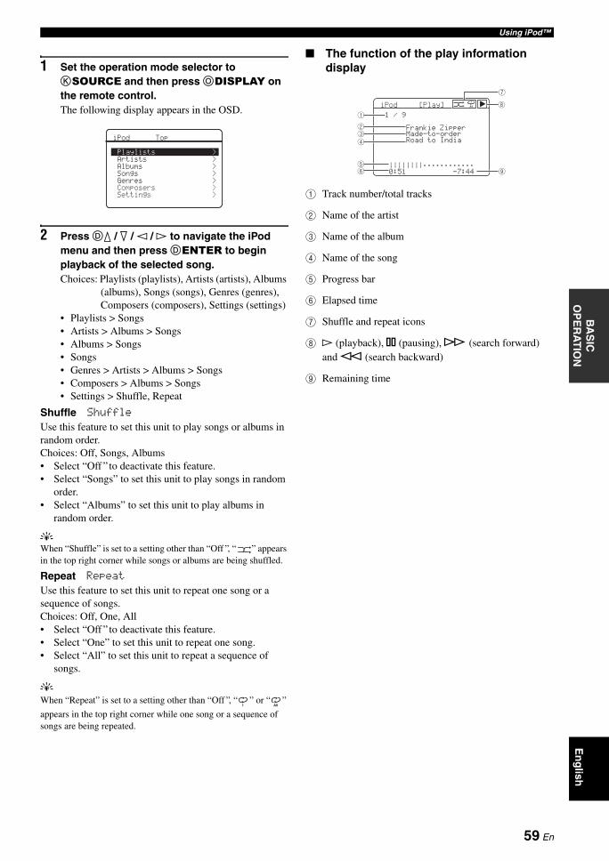
Using iPod™B
AS
IC
OP
ER
AT
ION
En
glish
1 Set the operation mode selector to KSOURCE and then press ODISPLAY on the remote control.The following display appears in the OSD.
2 Press Dk / n / l / h to navigate the iPod menu and then press DENTER to begin playback of the selected song.Choices: Playlists (playlists), Artists (artists), Albums
(albums), Songs (songs), Genres (genres), Composers (composers), Settings (settings)
• Playlists > Songs• Artists > Albums > Songs• Albums > Songs• Songs• Genres > Artists > Albums > Songs• Composers > Albums > Songs• Settings > Shuffle, Repeat
Shuffle ShuffleUse this feature to set this unit to play songs or albums in random order.Choices: Off, Songs, Albums• Select “Off ” to deactivate this feature.• Select “Songs” to set this unit to play songs in random
order.• Select “Albums” to set this unit to play albums in
random order.
yWhen “Shuffle” is set to a setting other than “Off ”, “ ” appears in the top right corner while songs or albums are being shuffled.
Repeat RepeatUse this feature to set this unit to repeat one song or a sequence of songs.Choices: Off, One, All• Select “Off ” to deactivate this feature.• Select “One” to set this unit to repeat one song.• Select “All” to set this unit to repeat a sequence of
songs.
yWhen “Repeat” is set to a setting other than “Off ”, “ ” or “ ”
appears in the top right corner while one song or a sequence of songs are being repeated.
The function of the play information display
1 Track number/total tracks
2 Name of the artist
3 Name of the album
4 Name of the song
5 Progress bar
6 Elapsed time
7 Shuffle and repeat icons
8 h (playback), e (pausing), f (search forward) and w (search backward)
9 Remaining time
>>>>>>>
Playlists ArtistsAlbumsSongsGenresComposersSettings
iPod Top
1 All
iPod[Play]
1/9FrankieZipperMade-to-orderRoadtoIndia||||||||;;;;;;;;;;;;0:51-7:44
All
1
234
56 9
8
7
59 En
RECORDING
Recording adjustments and other operations are performed from the recording components. Refer to the operating instructions for those components.
• When this unit is set to the standby mode, you cannot record between other components connected to this unit.• TONE CONTROL (see page 48) and VOLUME settings, the speaker level (see page 74) and the sound field programs (see page 42)
do not affect recorded material.• The source connected to the MULTI CH INPUT jacks of this unit cannot be recorded.• The XM Satellite Radio signals cannot be output at the AUDIO OUT (REC) jacks.• Digital signals input at the DIGITAL INPUT jacks are not output at the analog AUDIO OUT (REC) jacks for recording. Likewise,
analog signals input at the AUDIO IN jacks are not output at the DIGITAL OUTPUT jack. Therefore, if your source component is connected to provide only digital or analog signals, you can only record digital or analog signals.
• A given input source is not output on the same OUT (REC) channel.• S-video and composite video signals pass independently through the video circuits of this unit. Therefore, when recording or dubbing
video signals input from a video source component that provides only an S-video or a composite video signal, you can only record an S-video or a composite video signal on your VCR.
• The analog audio signals input at the DOCK terminal can be output at the analog AUDIO OUT (REC) jacks for recording.• Check the copyright laws in your country to record from CDs, radio, etc. Recording of copyrighted material may infringe copyright
laws.
yDo a test recording before you start an actual recording.
1 Turn on all the connected components.
2 Rotate the IINPUT selector (or press one of the input selector buttons (A)) to select the source component you want to record from.
3 Start playback on the selected source component or select a broadcast station.
4 Start recording on the recording component.
Recording
Caution
The DTS signal is a digital bitstream. Attempting to digitally record the DTS bitstream will result in noise being recorded. Therefore, if you want to use this unit to record sources encoded in DTS, the following considerations and adjustments need to be made. To play DTS-encoded DVDs and CDs (when using a digital audio connection) on your DTS-compatible player, follow its operating instructions to make a setting so that the analog signal will be output from the player.
Notes
If you play back a video source that uses scrambled or encoded signals to prevent it from being dubbed, the picture itself may be disturbed due to those signals.
60 En
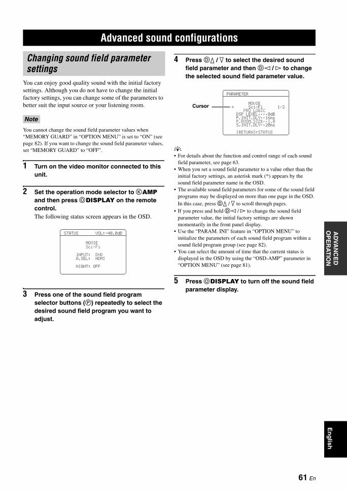
ADVANCED SOUND CONFIGURATIONSA
DVA
NC
ED
O
PE
RA
TIO
NE
ng
lish
You can enjoy good quality sound with the initial factory settings. Although you do not have to change the initial factory settings, you can change some of the parameters to better suit the input source or your listening room.
You cannot change the sound field parameter values when “MEMORY GUARD” in “OPTION MENU” is set to “ON” (see page 82). If you want to change the sound field parameter values, set “MEMORY GUARD” to “OFF”.
1 Turn on the video monitor connected to this unit.
2 Set the operation mode selector to KAMP and then press ODISPLAY on the remote control.The following status screen appears in the OSD.
3 Press one of the sound field program selector buttons (P) repeatedly to select the desired sound field program you want to adjust.
4 Press Dk / n to select the desired sound field parameter and then Dl / h to change the selected sound field parameter value.
y• For details about the function and control range of each sound
field parameter, see page 63.• When you set a sound field parameter to a value other than the
initial factory settings, an asterisk mark (*) appears by the sound field parameter name in the OSD.
• The available sound field parameters for some of the sound field programs may be displayed on more than one page in the OSD. In this case, press Dk / n to scroll through pages.
• If you press and hold Dl / h to change the sound field parameter value, the initial factory settings are shown momentarily in the front panel display.
• Use the “PARAM. INI” feature in “OPTION MENU” to initialize the parameters of each sound field program within a sound field program group (see page 82).
• You can select the amount of time that the current status is displayed in the OSD by using the “OSD-AMP” parameter in “OPTION MENU” (see page 81).
5 Press ODISPLAY to turn off the sound field parameter display.
Advanced sound configurations
Changing sound field parameter settings
Note
NIGHT:OFFA.SEL:HDMIINPUT:DVDSci-FiMOVIE
STATUSVOL:-40.0dB
PARAMETER
MOVIE. Sci-Fi 1/2
PROLOGICDSP LEVEL;;;;0dBP.INIT.DLY;;16msP.ROOM.SIZE;;1.0S.INIT.DLY;;20ms
[RETURN]:STATUS
Cursor
61 En
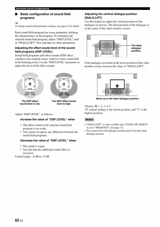
Advanced sound configurations
Basic configuration of sound field programs
yTo change sound field parameter settings, see page 61 for details.
Each sound field program has some parameters defining the characteristics of the program. To customize the selected sound field program, adjust “DSP LEVEL” and/or “DIALG.LIFT” first, and then try other parameters.
Adjusting the effect sound level of the sound field programs (DSP LEVEL)Sound field programs add effect sounds (DSP effect sounds) to the original source sound to create sound field in the listening room. Use the “DSP LEVEL” parameter to adjust the level of the effect sounds.
Adjust “DSP LEVEL” as follows:
Increase the value of “DSP LEVEL” when
• The effect sound of the selected sound field program is too weak.
• You cannot recognize any difference between the sound field programs.
Decrease the value of “DSP LEVEL” when
• The sound is vague.• You feel that the additional sound effect is
excessive.Control range: –6 dB to +3 dB
Adjusting the vertical dialogue position (DIALG.LIFT)Use this feature to adjust the vertical position of the dialogues in movies. The ideal position of the dialogues is at the center of the video monitor screen.
If the dialogues are heard at the lower position of the video monitor screen, increase the value of “DIALG.LIFT”.
Choices: 0, 1, 2, 3, 4, 5“0” (initial setting) is the lowest position, and “5” is the highest position.
• “DIALG.LIFT” is only available only “EXTRA SP ASSIGN” is set to “PRESENCE” (see page 72).
• You cannot move the dialogue position down from the initial dialogue position.
The DSP effect sound level is low.
The DSP effect sound level is high.
Notes
The ideal dialogue position.
Move up to the ideal dialogue position.
62 En
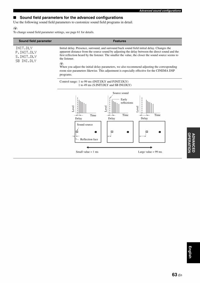
Advanced sound configurationsA
DVA
NC
ED
O
PE
RA
TIO
NE
ng
lish
Sound field parameters for the advanced configurationsUse the following sound field parameters to customize sound field programs in detail.
yTo change sound field parameter settings, see page 61 for details.
Sound field parameter Features
INIT.DLYP.INIT.DLYS.INIT.DLYSB INI.DLY
Initial delay. Presence, surround, and surround back sound field initial delay. Changes the apparent distance from the source sound by adjusting the delay between the direct sound and the first reflection heard by the listener. The smaller the value, the closer the sound source seems to the listener.
yWhen you adjust the initial delay parameters, we also recommend adjusting the corresponding room size parameters likewise. This adjustment is especially effective for the CINEMA DSP programs.
Control range: 1 to 99 ms (INIT.DLY and P.INIT.DLY)1 to 49 ms (S.INIT.DLY and SB INI.DLY)
Source sound
Early reflections
Time Time TimeDelay Delay Delay
Sound source
Reflection face
Lev
el
Small value = 1 ms Large value = 99 ms
Lev
el
Lev
el
63 En
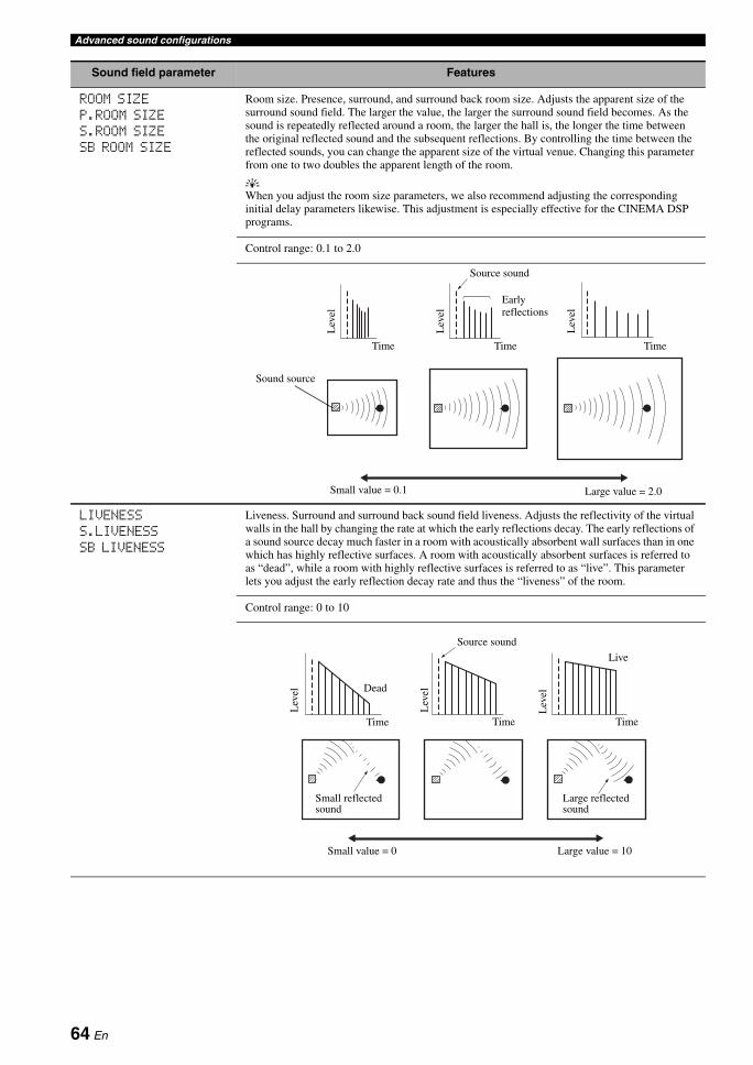
Advanced sound configurations
ROOM SIZEP.ROOM SIZES.ROOM SIZESB ROOM SIZE
Room size. Presence, surround, and surround back room size. Adjusts the apparent size of the surround sound field. The larger the value, the larger the surround sound field becomes. As the sound is repeatedly reflected around a room, the larger the hall is, the longer the time between the original reflected sound and the subsequent reflections. By controlling the time between the reflected sounds, you can change the apparent size of the virtual venue. Changing this parameter from one to two doubles the apparent length of the room.
yWhen you adjust the room size parameters, we also recommend adjusting the corresponding initial delay parameters likewise. This adjustment is especially effective for the CINEMA DSP programs.
Control range: 0.1 to 2.0
LIVENESSS.LIVENESSSB LIVENESS
Liveness. Surround and surround back sound field liveness. Adjusts the reflectivity of the virtual walls in the hall by changing the rate at which the early reflections decay. The early reflections of a sound source decay much faster in a room with acoustically absorbent wall surfaces than in one which has highly reflective surfaces. A room with acoustically absorbent surfaces is referred to as “dead”, while a room with highly reflective surfaces is referred to as “live”. This parameter lets you adjust the early reflection decay rate and thus the “liveness” of the room.
Control range: 0 to 10
Sound field parameter Features
Lev
el
Lev
el
Lev
el
Time Time Time
Source sound
Early reflections
Small value = 0.1 Large value = 2.0
Sound source
Source sound
Lev
el
Lev
el
Lev
elDead
Live
Time Time Time
Small reflected sound
Large reflected sound
Small value = 0 Large value = 10
64 En

Advanced sound configurationsA
DVA
NC
ED
O
PE
RA
TIO
NE
ng
lish
REV.TIME Reverberation time. Adjusts the amount of time taken for the dense, subsequent reverberation sound to decay by 60 dB at 1 kHz. This changes the apparent size of the acoustic environment over an extremely wide range. Set a longer reverberation time for “dead” sources and listening room environments, and a shorter time for “live” sources and listening room environments.
Control range: 1.0 to 5.0 s
REV.DELAY Reverberation delay. Adjusts the time difference between the beginning of the direct sound and the beginning of the reverberation sound. The larger the value, the later the reverberation sound begins. A later reverberation sound makes you feel as if you are in a larger acoustic environment.
Control range: 0 to 250 ms
REV.LEVEL Reverberation level. Adjusts the volume of the reverberation sound. The larger the value, the stronger the reverberation becomes.
Control range: 0 to 100%
Sound field parameter Features
Reverberation ReverberationSource sound
REV.TIME REV.TIME REV.TIMESound source Short
reverberationLong reverberation
Small value = 1.0 s Large value = 5.0 s
Early reflections
60 dB 60 dB 60 dB
(dB)
Lev
el Source sound
Reverberation
REV.TIMEREV.DELAY
Time
60 dB
Source sound
Lev
el
REV. LEVEL
Time
65 En
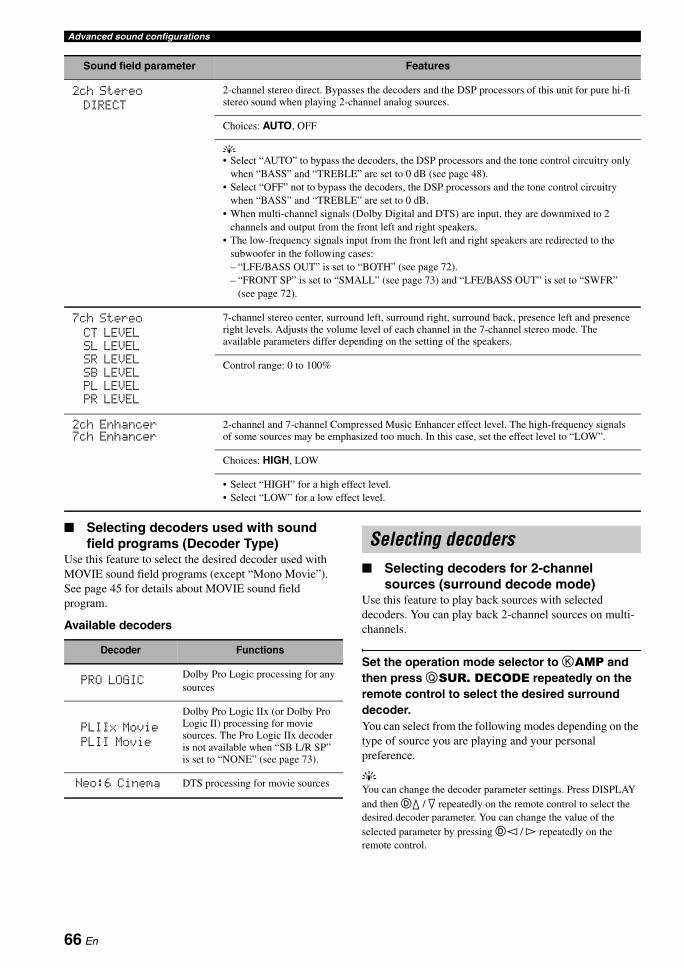
Advanced sound configurations
Selecting decoders used with sound field programs (Decoder Type)
Use this feature to select the desired decoder used with MOVIE sound field programs (except “Mono Movie”). See page 45 for details about MOVIE sound field program.
Available decoders
Selecting decoders for 2-channel sources (surround decode mode)
Use this feature to play back sources with selected decoders. You can play back 2-channel sources on multi-channels.
Set the operation mode selector to KAMP and then press QSUR. DECODE repeatedly on the remote control to select the desired surround decoder.You can select from the following modes depending on the type of source you are playing and your personal preference.
yYou can change the decoder parameter settings. Press DISPLAY and then Dk / n repeatedly on the remote control to select the desired decoder parameter. You can change the value of the selected parameter by pressing Dl / h repeatedly on the remote control.
2ch StereoDIRECT
2-channel stereo direct. Bypasses the decoders and the DSP processors of this unit for pure hi-fi stereo sound when playing 2-channel analog sources.
Choices: AUTO, OFF
y• Select “AUTO” to bypass the decoders, the DSP processors and the tone control circuitry only
when “BASS” and “TREBLE” are set to 0 dB (see page 48).• Select “OFF” not to bypass the decoders, the DSP processors and the tone control circuitry
when “BASS” and “TREBLE” are set to 0 dB.• When multi-channel signals (Dolby Digital and DTS) are input, they are downmixed to 2
channels and output from the front left and right speakers.• The low-frequency signals input from the front left and right speakers are redirected to the
subwoofer in the following cases:– “LFE/BASS OUT” is set to “BOTH” (see page 72).– “FRONT SP” is set to “SMALL” (see page 73) and “LFE/BASS OUT” is set to “SWFR”
(see page 72).
7ch StereoCT LEVELSL LEVELSR LEVELSB LEVELPL LEVELPR LEVEL
7-channel stereo center, surround left, surround right, surround back, presence left and presence right levels. Adjusts the volume level of each channel in the 7-channel stereo mode. The available parameters differ depending on the setting of the speakers.
Control range: 0 to 100%
2ch Enhancer7ch Enhancer
2-channel and 7-channel Compressed Music Enhancer effect level. The high-frequency signals of some sources may be emphasized too much. In this case, set the effect level to “LOW”.
Choices: HIGH, LOW
• Select “HIGH” for a high effect level.• Select “LOW” for a low effect level.
Sound field parameter Features
Decoder Functions
PRO LOGICDolby Pro Logic processing for any sources
PLIIx MoviePLII Movie
Dolby Pro Logic IIx (or Dolby Pro Logic II) processing for movie sources. The Pro Logic IIx decoder is not available when “SB L/R SP” is set to “NONE” (see page 73).
Neo:6 Cinema DTS processing for movie sources
Selecting decoders
66 En
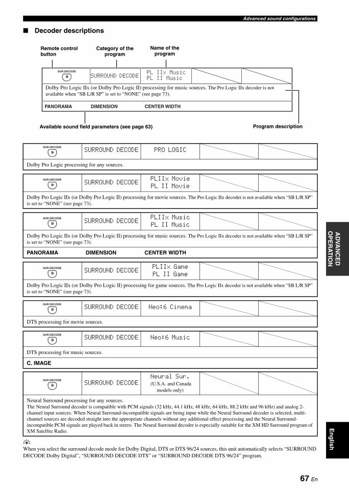
Advanced sound configurationsA
DVA
NC
ED
O
PE
RA
TIO
NE
ng
lish
Decoder descriptions
yWhen you select the surround decode mode for Dolby Digital, DTS or DTS 96/24 sources, this unit automatically selects “SURROUND DECODE Dolby Digital”, “SURROUND DECODE DTS” or “SURROUND DECODE DTS 96/24” program.
SURROUND DECODE PRO LOGIC
Dolby Pro Logic processing for any sources.
SURROUND DECODEPLIIx MoviePL II Movie
Dolby Pro Logic IIx (or Dolby Pro Logic II) processing for movie sources. The Pro Logic IIx decoder is not available when “SB L/R SP” is set to “NONE” (see page 73).
SURROUND DECODEPLIIx MusicPL II Music
Dolby Pro Logic IIx (or Dolby Pro Logic II) processing for music sources. The Pro Logic IIx decoder is not available when “SB L/R SP” is set to “NONE” (see page 73).
PANORAMA DIMENSION CENTER WIDTH
SURROUND DECODEPLIIx GamePL II Game
Dolby Pro Logic IIx (or Dolby Pro Logic II) processing for game sources. The Pro Logic IIx decoder is not available when “SB L/R SP” is set to “NONE” (see page 73).
CENTER WIDTHDIMENSION
PLIIMusicPLIIxMusic
SURROUND DECODE
PANORAMA
9
SUR.DECODE
Dolby Pro Logic IIx (or Dolby Pro Logic II) processing for music sources. The Pro Logic IIx decoder is not available when “SB L/R SP” is set to “NONE” (see page 73).
Available sound field parameters (see page 63) Program description
Remote control button
Name of the program
Category of the program
9
SUR.DECODE
9
SUR.DECODE
9
SUR.DECODE
9
SUR.DECODE
SURROUND DECODE Neo:6 Cinema
DTS processing for movie sources.
9
SUR.DECODE
SURROUND DECODE Neo:6 Music
DTS processing for music sources.
C. IMAGE
SURROUND DECODENeural Sur. (U.S.A. and Canada
models only)
Neural Surround processing for any sources. The Neural Surround decoder is compatible with PCM signals (32 kHz, 44.1 kHz, 48 kHz, 64 kHz, 88.2 kHz and 96 kHz) and analog 2-channel input sources. When Neural Surround-incompatible signals are being input while the Neural Surround decoder is selected, multi-channel sources are decoded straight into the appropriate channels without any additional effect processing and the Neural Surround-incompatible PCM signals are played back in stereo. The Neural Surround decoder is especially suitable for the XM HD Surround program of XM Satellite Radio.
9
SUR.DECODE
9
SUR.DECODE
67 En
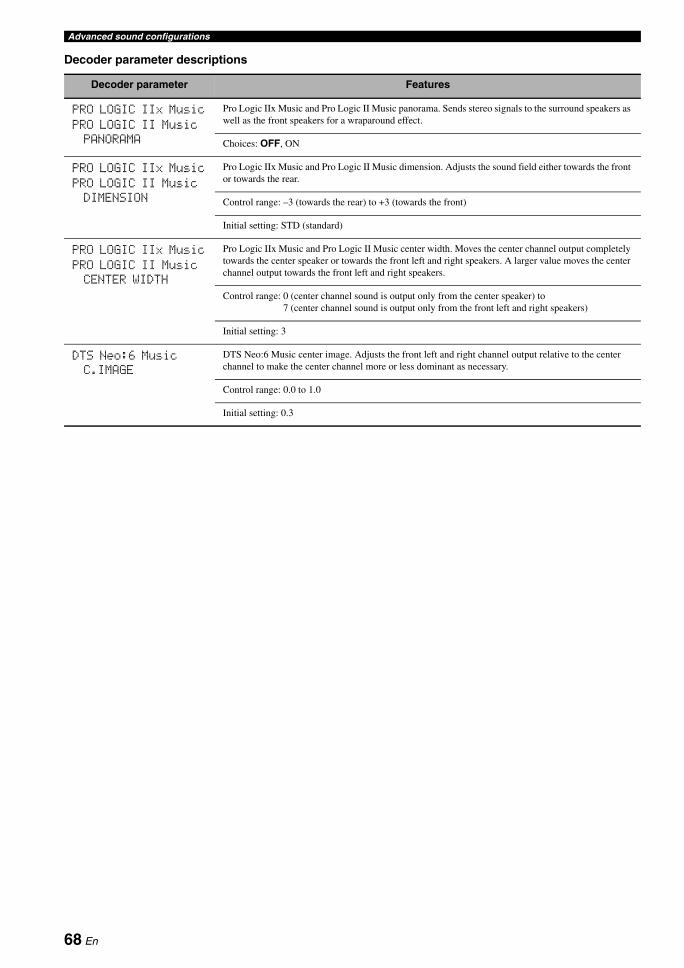
Advanced sound configurations
Decoder parameter descriptions
Decoder parameter Features
PRO LOGIC IIx Music
PRO LOGIC II MusicPANORAMA
Pro Logic IIx Music and Pro Logic II Music panorama. Sends stereo signals to the surround speakers as well as the front speakers for a wraparound effect.
Choices: OFF, ON
PRO LOGIC IIx Music
PRO LOGIC II MusicDIMENSION
Pro Logic IIx Music and Pro Logic II Music dimension. Adjusts the sound field either towards the front or towards the rear.
Control range: –3 (towards the rear) to +3 (towards the front)
Initial setting: STD (standard)
PRO LOGIC IIx Music
PRO LOGIC II MusicCENTER WIDTH
Pro Logic IIx Music and Pro Logic II Music center width. Moves the center channel output completely towards the center speaker or towards the front left and right speakers. A larger value moves the center channel output towards the front left and right speakers.
Control range: 0 (center channel sound is output only from the center speaker) to 7 (center channel sound is output only from the front left and right speakers)
Initial setting: 3
DTS Neo:6 MusicC.IMAGE
DTS Neo:6 Music center image. Adjusts the front left and right channel output relative to the center channel to make the center channel more or less dominant as necessary.
Control range: 0.0 to 1.0
Initial setting: 0.3
68 En
CUSTOMIZING THIS UNIT (MANUAL SETUP)A
DVA
NC
ED
O
PE
RA
TIO
NE
ng
lish
You can use the following parameters in “SET MENU” to adjust a variety of system settings and customize the way this unit operates. Change the initial settings (indicated in bold under each parameter) to reflect the needs of your listening environment.
Auto setup AUTO SETUP
Use this feature to automatically adjust speaker and system parameters (see page 28).
Manual setup MANUAL SETUPUse this feature to manually adjust speaker and system parameters.
Sound menu 1 SOUND MENUUse this menu to manually adjust any speaker settings, alter the quality and tone of the sound output by the system or compensate for video signal processing delays when using LCD monitors or projectors.
Input menu 2 INPUT MENUUse this menu to manually reassign the input/output jacks, select the input mode or rename the input source.
Customizing this unit (MANUAL SETUP)
Parameter Features Page
A)SPEAKER SETSelects the size of each speaker, the speakers for low-frequency signal output, the crossover frequency, and the assignment of the EXTRA SP terminal.
72
B)SPEAKER LEVEL Adjusts the output level of each speaker. 74
C)SP DISTANCE Adjusts the distance of each speaker. 75
D)EQUALIZER Adjusts the tonal quality of the center speaker. 75
E)LFE LEVEL Adjusts the output level of the LFE channel for Dolby Digital or DTS signals. 76
F)DYNAMIC RANGE Adjusts the dynamic range of Dolby Digital or DTS signals. 76
G)AUDIO SET Adjusts the muting level, audio delay, maximum volume level and initial volume level. 76
H)HDMI SET Selects the component to play back HDMI audio signals. 77
I)EXTD SUR. Selects the mode of the decoders for the 6.1/7.1-channel playback. 77
Parameter Features Page
A)I/O ASSIGNMENT Assigns the input/output jacks of this unit according to the component to be used. 78
B)INPUT RENAME Changes the name of the input source. 79
C)VOLUME TRIM Adjusts the output volume of each input source. 80
D)DECODER MODESelects the input mode for the sources connected to the DIGITAL INPUT jacks on the rear panel of this unit.
80
E)MULTI CH SET Sets the input channel numbers and other parameters of the multi channel input. 80
69 En
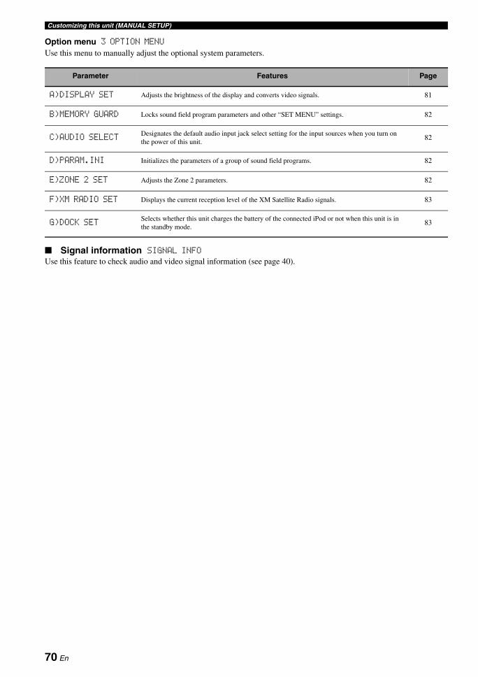
Customizing this unit (MANUAL SETUP)
Option menu 3 OPTION MENUUse this menu to manually adjust the optional system parameters.
Signal information SIGNAL INFOUse this feature to check audio and video signal information (see page 40).
Parameter Features Page
A)DISPLAY SET Adjusts the brightness of the display and converts video signals. 81
B)MEMORY GUARD Locks sound field program parameters and other “SET MENU” settings. 82
C)AUDIO SELECTDesignates the default audio input jack select setting for the input sources when you turn on the power of this unit.
82
D)PARAM.INI Initializes the parameters of a group of sound field programs. 82
E)ZONE 2 SET Adjusts the Zone 2 parameters. 82
F)XM RADIO SET Displays the current reception level of the XM Satellite Radio signals. 83
G)DOCK SETSelects whether this unit charges the battery of the connected iPod or not when this unit is in the standby mode.
83
70 En
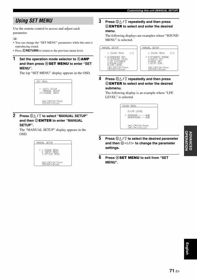
Customizing this unit (MANUAL SETUP)A
DVA
NC
ED
O
PE
RA
TIO
NE
ng
lish
Use the remote control to access and adjust each parameter.
y• You can change the “SET MENU” parameters while this unit is
reproducing sound.• Press ERETURN to return to the previous menu level.
1 Set the operation mode selector to KAMP and then press NSET MENU to enter “SET MENU”.The top “SET MENU” display appears in the OSD.
2 Press Dk / n to select “MANUAL SETUP” and then DENTER to enter “MANUAL SETUP”.The “MANUAL SETUP” display appears in the OSD.
3 Press Dk / n repeatedly and then press DENTER to select and enter the desired menu.The following displays are examples where “SOUND MENU” is selected.
4 Press Dk / n repeatedly and then press DENTER to select and enter the desired submenu.The following display is an example where “LFE LEVEL” is selected.
5 Press Dk / n to select the desired parameter and then Dl / h to change the parameter settings.
6 Press NSET MENU to exit from “SET MENU”.
Using SET MENU
SET MENU
. ;AUTO SETUP;MANUAL SETUP
.A;SIGNAL INFO
[ ]/[ ]:Up/Down[ENTER]:Enter
p
p
MANUAL SETUP
. 1 SOUND MENU2 INPUT MENU3 OPTION MENU
[ ]/[ ]:Up/Down
p
p[ENTER]:Enter
MANUAL SETUP
1 SOUND MENU 1/2
. A)SPEAKER SETB)SPEAKER LEVELC)SP DISTANCED)EQUALIZERE)LFE LEVEL[ ]/[ ]:Up/Down
p
p[ENTER]:Enter
MANUAL SETUP
1 SOUND MENU 2/2
. F)DYNAMIC RANGEG)AUDIO SETH)HDMI SETI)EXTD SUR.
[ ]/[ ]:Up/Down
p
p[ENTER]:Enter
SOUND MENU
E)LFE LEVEL
. SPEAKER;;;;;;0dBHEADPHONE;;;;0dB
[ ]/[ ]:Up/Down
p
pp [[ ]/[ ]:Adjust
71 En
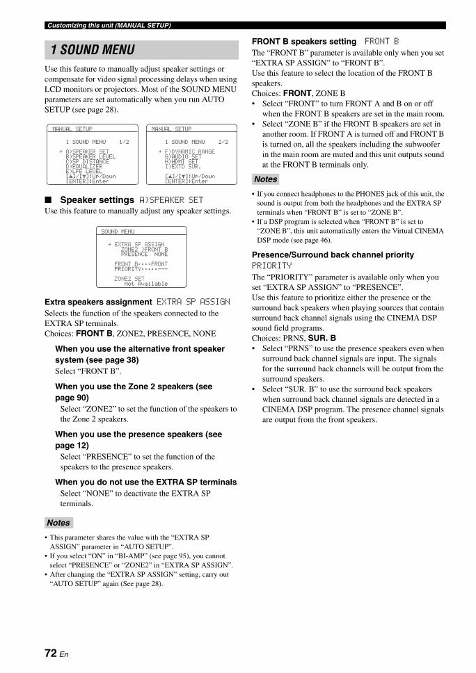
Customizing this unit (MANUAL SETUP)
Use this feature to manually adjust speaker settings or compensate for video signal processing delays when using LCD monitors or projectors. Most of the SOUND MENU parameters are set automatically when you run AUTO SETUP (see page 28).
Speaker settings A)SPEAKER SETUse this feature to manually adjust any speaker settings.
Extra speakers assignment EXTRA SP ASSIGNSelects the function of the speakers connected to the EXTRA SP terminals.Choices: FRONT B, ZONE2, PRESENCE, NONE
When you use the alternative front speaker system (see page 38)Select “FRONT B”.
When you use the Zone 2 speakers (see page 90)
Select “ZONE2” to set the function of the speakers to the Zone 2 speakers.
When you use the presence speakers (see page 12)
Select “PRESENCE” to set the function of the speakers to the presence speakers.
When you do not use the EXTRA SP terminalsSelect “NONE” to deactivate the EXTRA SP terminals.
• This parameter shares the value with the “EXTRA SP ASSIGN” parameter in “AUTO SETUP”.
• If you select “ON” in “BI-AMP” (see page 95), you cannot select “PRESENCE” or “ZONE2” in “EXTRA SP ASSIGN”.
• After changing the “EXTRA SP ASSIGN” setting, carry out “AUTO SETUP” again (See page 28).
FRONT B speakers setting FRONT BThe “FRONT B” parameter is available only when you set “EXTRA SP ASSIGN” to “FRONT B”.Use this feature to select the location of the FRONT B speakers.Choices: FRONT, ZONE B• Select “FRONT” to turn FRONT A and B on or off
when the FRONT B speakers are set in the main room.• Select “ZONE B” if the FRONT B speakers are set in
another room. If FRONT A is turned off and FRONT B is turned on, all the speakers including the subwoofer in the main room are muted and this unit outputs sound at the FRONT B terminals only.
• If you connect headphones to the PHONES jack of this unit, the sound is output from both the headphones and the EXTRA SP terminals when “FRONT B” is set to “ZONE B”.
• If a DSP program is selected when “FRONT B” is set to “ZONE B”, this unit automatically enters the Virtual CINEMA DSP mode (see page 46).
Presence/Surround back channel priority PRIORITY
The “PRIORITY” parameter is available only when you set “EXTRA SP ASSIGN” to “PRESENCE”.Use this feature to prioritize either the presence or the surround back speakers when playing sources that contain surround back channel signals using the CINEMA DSP sound field programs.Choices: PRNS, SUR. B• Select “PRNS” to use the presence speakers even when
surround back channel signals are input. The signals for the surround back channels will be output from the surround speakers.
• Select “SUR. B” to use the surround back speakers when surround back channel signals are detected in a CINEMA DSP program. The presence channel signals are output from the front speakers.
1 SOUND MENU
Notes
MANUAL SETUP
1 SOUND MENU 1/2
. A)SPEAKER SETB)SPEAKER LEVELC)SP DISTANCED)EQUALIZERE)LFE LEVEL[ ]/[ ]:Up/Down
p
p[ENTER]:Enter
MANUAL SETUP
1 SOUND MENU 2/2
. F)DYNAMIC RANGEG)AUDIO SETH)HDMI SETI)EXTD SUR.
[ ]/[ ]:Up/Down
p
p[ENTER]:Enter
SOUND MENU
. EXTRA SP ASSIGNZONE2 >FRONT BPRESENCE NONE
FRONT B;;;;FRONTPRIORITY;;;;;---
ZONE2 SETNot Available
Notes
72 En
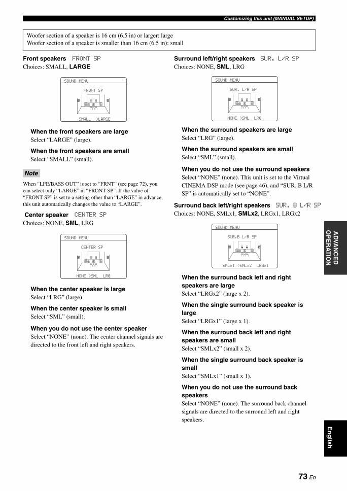
Customizing this unit (MANUAL SETUP)A
DVA
NC
ED
O
PE
RA
TIO
NE
ng
lish
Front speakers FRONT SPChoices: SMALL, LARGE
When the front speakers are largeSelect “LARGE” (large).
When the front speakers are smallSelect “SMALL” (small).
When “LFE/BASS OUT” is set to “FRNT” (see page 72), you can select only “LARGE” in “FRONT SP”. If the value of “FRONT SP” is set to a setting other than “LARGE” in advance, this unit automatically changes the value to “LARGE”.
Center speaker CENTER SPChoices: NONE, SML, LRG
When the center speaker is largeSelect “LRG” (large).
When the center speaker is smallSelect “SML” (small).
When you do not use the center speakerSelect “NONE” (none). The center channel signals are directed to the front left and right speakers.
Surround left/right speakers SUR. L/R SP
Choices: NONE, SML, LRG
When the surround speakers are largeSelect “LRG” (large).
When the surround speakers are smallSelect “SML” (small).
When you do not use the surround speakersSelect “NONE” (none). This unit is set to the Virtual CINEMA DSP mode (see page 46), and “SUR. B L/R SP” is automatically set to “NONE”.
Surround back left/right speakers SUR. B L/R SP
Choices: NONE, SMLx1, SMLx2, LRGx1, LRGx2
When the surround back left and right speakers are largeSelect “LRGx2” (large x 2).
When the single surround back speaker is largeSelect “LRGx1” (large x 1).
When the surround back left and right speakers are smallSelect “SMLx2” (small x 2).
When the single surround back speaker is smallSelect “SMLx1” (small x 1).
When you do not use the surround back speakersSelect “NONE” (none). The surround back channel signals are directed to the surround left and right speakers.
Woofer section of a speaker is 16 cm (6.5 in) or larger: largeWoofer section of a speaker is smaller than 16 cm (6.5 in): small
Note
SOUND MENU
FRONT SP
SMALL >LARGE
SOUND MENU
CENTER SP
NONE >SML LRG
SOUND MENU
SUR. L/R SP
NONE >SML LRG
SOUND MENU
SUR.B L/R SP
SMLx1 >SMLx2 LRGx1
73 En
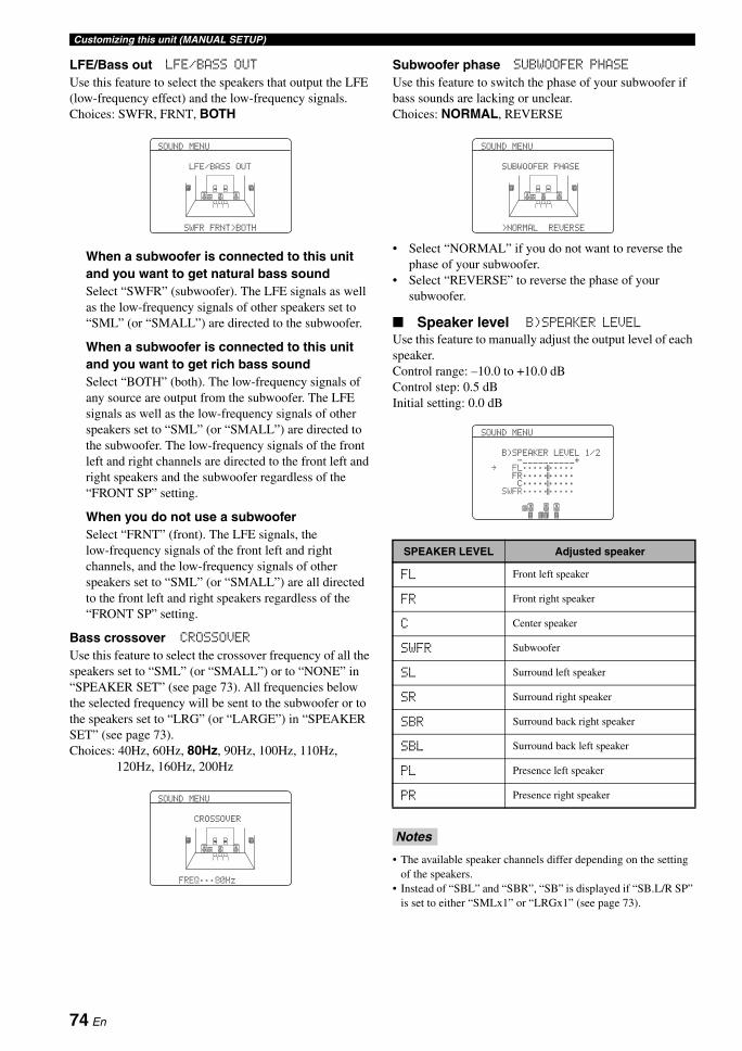
Customizing this unit (MANUAL SETUP)
LFE/Bass out LFE/BASS OUTUse this feature to select the speakers that output the LFE (low-frequency effect) and the low-frequency signals.Choices: SWFR, FRNT, BOTH
When a subwoofer is connected to this unit and you want to get natural bass soundSelect “SWFR” (subwoofer). The LFE signals as well as the low-frequency signals of other speakers set to “SML” (or “SMALL”) are directed to the subwoofer.
When a subwoofer is connected to this unit and you want to get rich bass soundSelect “BOTH” (both). The low-frequency signals of any source are output from the subwoofer. The LFE signals as well as the low-frequency signals of other speakers set to “SML” (or “SMALL”) are directed to the subwoofer. The low-frequency signals of the front left and right channels are directed to the front left and right speakers and the subwoofer regardless of the “FRONT SP” setting.
When you do not use a subwooferSelect “FRNT” (front). The LFE signals, the low-frequency signals of the front left and right channels, and the low-frequency signals of other speakers set to “SML” (or “SMALL”) are all directed to the front left and right speakers regardless of the “FRONT SP” setting.
Bass crossover CROSSOVER
Use this feature to select the crossover frequency of all the speakers set to “SML” (or “SMALL”) or to “NONE” in “SPEAKER SET” (see page 73). All frequencies below the selected frequency will be sent to the subwoofer or to the speakers set to “LRG” (or “LARGE”) in “SPEAKER SET” (see page 73).Choices: 40Hz, 60Hz, 80Hz, 90Hz, 100Hz, 110Hz,
120Hz, 160Hz, 200Hz
Subwoofer phase SUBWOOFER PHASEUse this feature to switch the phase of your subwoofer if bass sounds are lacking or unclear.Choices: NORMAL, REVERSE
• Select “NORMAL” if you do not want to reverse the phase of your subwoofer.
• Select “REVERSE” to reverse the phase of your subwoofer.
Speaker level B)SPEAKER LEVEL
Use this feature to manually adjust the output level of each speaker.Control range: –10.0 to +10.0 dBControl step: 0.5 dBInitial setting: 0.0 dB
• The available speaker channels differ depending on the setting of the speakers.
• Instead of “SBL” and “SBR”, “SB” is displayed if “SB.L/R SP” is set to either “SMLx1” or “LRGx1” (see page 73).
SOUND MENU
LFE/BASS OUT
SWFR FRNT>BOTH
SOUND MENU
CROSSOVER
FREQ;;;80Hz
SPEAKER LEVEL Adjusted speaker
FL Front left speaker
FR Front right speaker
C Center speaker
SWFR Subwoofer
SL Surround left speaker
SR Surround right speaker
SBR Surround back right speaker
SBL Surround back left speaker
PL Presence left speaker
PR Presence right speaker
Notes
SOUND MENU
SUBWOOFER PHASE
>NORMAL REVERSE
SOUND MENU
B)SPEAKER LEVEL 1/2-__________+
. FL;;;;;;;;;;FR;;;;;;;;;;C;;;;;;;;;;
SWFR;;;;;;;;;;
74 En
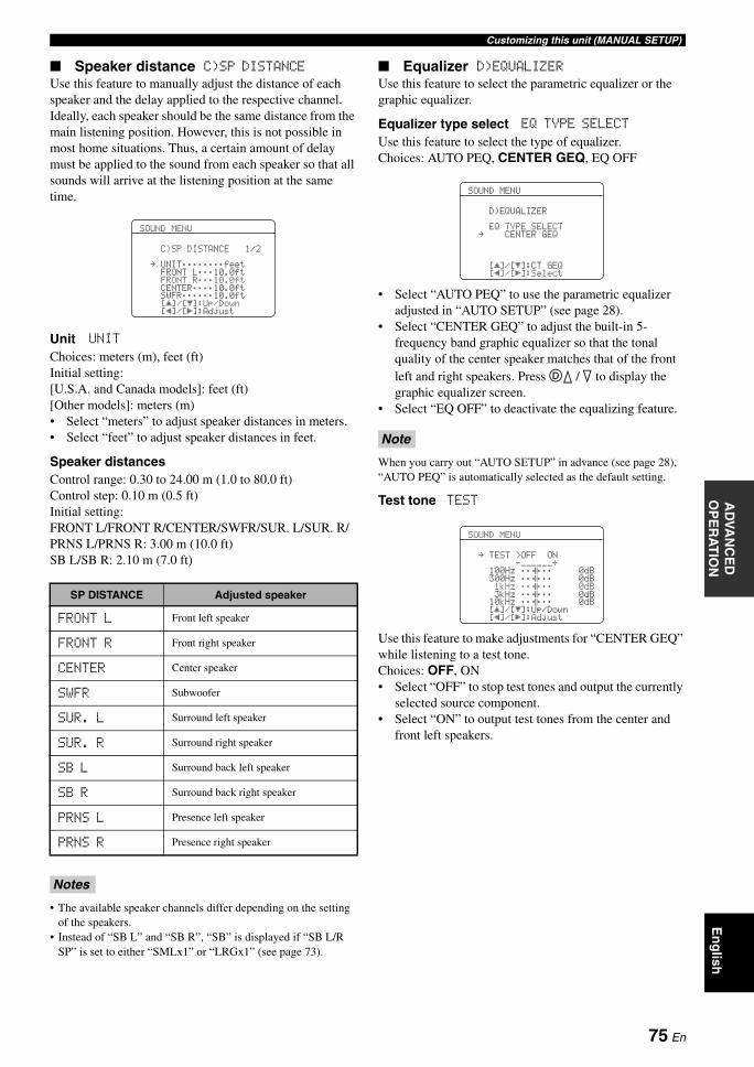
Customizing this unit (MANUAL SETUP)A
DVA
NC
ED
O
PE
RA
TIO
NE
ng
lish
Speaker distance C)SP DISTANCEUse this feature to manually adjust the distance of each speaker and the delay applied to the respective channel. Ideally, each speaker should be the same distance from the main listening position. However, this is not possible in most home situations. Thus, a certain amount of delay must be applied to the sound from each speaker so that all sounds will arrive at the listening position at the same time.
Unit UNITChoices: meters (m), feet (ft)Initial setting:[U.S.A. and Canada models]: feet (ft) [Other models]: meters (m)• Select “meters” to adjust speaker distances in meters.• Select “feet” to adjust speaker distances in feet.
Speaker distancesControl range: 0.30 to 24.00 m (1.0 to 80.0 ft)Control step: 0.10 m (0.5 ft)Initial setting:FRONT L/FRONT R/CENTER/SWFR/SUR. L/SUR. R/PRNS L/PRNS R: 3.00 m (10.0 ft)SB L/SB R: 2.10 m (7.0 ft)
• The available speaker channels differ depending on the setting of the speakers.
• Instead of “SB L” and “SB R”, “SB” is displayed if “SB L/R SP” is set to either “SMLx1” or “LRGx1” (see page 73).
Equalizer D)EQUALIZERUse this feature to select the parametric equalizer or the graphic equalizer.
Equalizer type select EQ TYPE SELECT
Use this feature to select the type of equalizer.Choices: AUTO PEQ, CENTER GEQ, EQ OFF
• Select “AUTO PEQ” to use the parametric equalizer adjusted in “AUTO SETUP” (see page 28).
• Select “CENTER GEQ” to adjust the built-in 5-frequency band graphic equalizer so that the tonal quality of the center speaker matches that of the front left and right speakers. Press Dk / n to display the graphic equalizer screen.
• Select “EQ OFF” to deactivate the equalizing feature.
When you carry out “AUTO SETUP” in advance (see page 28), “AUTO PEQ” is automatically selected as the default setting.
Test tone TEST
Use this feature to make adjustments for “CENTER GEQ” while listening to a test tone.Choices: OFF, ON• Select “OFF” to stop test tones and output the currently
selected source component.• Select “ON” to output test tones from the center and
front left speakers.
SP DISTANCE Adjusted speaker
FRONT L Front left speaker
FRONT R Front right speaker
CENTER Center speaker
SWFR Subwoofer
SUR. L Surround left speaker
SUR. R Surround right speaker
SB L Surround back left speaker
SB R Surround back right speaker
PRNS L Presence left speaker
PRNS R Presence right speaker
Notes
SOUND MENU
C)SP DISTANCE 1/2
. UNIT;;;;;;;;feetFRONT L;;;10.0ftFRONT R;;;10.0ftCENTER;;;;10.0ftSWFR;;;;;;10.0ft[ ]/[ ]:Up/Down[ ]/[ ]:Adjust
p
pp [
Note
SOUND MENU
D)EQUALIZER
EQ TYPE SELECT. CENTER GEQ
[ ]/[]:CT GEQ[ ]/[ ]:Select
pp
p [
SOUND MENU
. TEST >OFF ON-______+
100Hz ;;;;;; 0dB300Hz ;;;;;; 0dB1kHz ;;;;;; 0dB3kHz ;;;;;; 0dB
10kHz ;;;;;; 0dB[ ]/[ ]:Up/Down
p
pp [[ ]/[ ]:Adjust
75 En
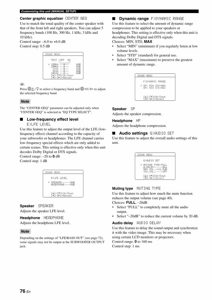
Customizing this unit (MANUAL SETUP)
Center graphic equalizer CENTER GEQUse to match the tonal quality of the center speaker with that of the front left and right speakers. You can adjust 5 frequency bands (100 Hz, 300 Hz, 1 kHz, 3 kHz and 10 kHz).Control range: –6.0 to +6.0 dBControl step: 0.5 dB
yPress Dk / n to select a frequency band and Dl / h to adjust the selected frequency band.
The “CENTER GEQ” parameter can be adjusted only when “CENTER GEQ” is selected in “EQ TYPE SELECT”.
Low-frequency effect level E)LFE LEVEL
Use this feature to adjust the output level of the LFE (low-frequency effect) channel according to the capacity of your subwoofer or headphones. The LFE channel carries low-frequency special effects which are only added to certain scenes. This setting is effective only when this unit decodes Dolby Digital or DTS signals.Control range: –20 to 0 dBControl step: 1 dB
Speaker SPEAKERAdjusts the speaker LFE level.
Headphone HEADPHONEAdjusts the headphone LFE level.
Depending on the settings of “LFE/BASS OUT” (see page 72), some signals may not be output at the SUBWOOFER OUTPUT jack.
Dynamic range F)DYNAMIC RANGEUse this feature to select the amount of dynamic range compression to be applied to your speakers or headphones. This setting is effective only when this unit is decoding Dolby Digital and DTS signals.Choices: MIN, STD, MAX• Select “MIN” (minimum) if you regularly listen at low
volume levels.• Select “STD” (standard) for general use.• Select “MAX” (maximum) to preserve the greatest
amount of dynamic range.
Speaker SPAdjusts the speaker compression.
Headphone HPAdjusts the headphone compression.
Audio settings G)AUDIO SETUse this feature to adjust the overall audio settings of this unit.
Muting type MUTING TYPEUse this feature to adjust how much the mute function reduces the output volume (see page 40).Choices: FULL, –20dB• Select “FULL” to completely mute all the audio
output.• Select “–20dB” to reduce the current volume by 20 dB.
Audio delay AUDIO DELAYUse this feature to delay the sound output and synchronize it with the video image. This may be necessary when using certain LCD monitors or projectors.Control range: 0 to 160 msControl step: 1 ms
Note
Note
SOUND MENU
TEST >OFF ON-______+
. 100Hz ;;;;;; 0dB300Hz ;;;;;; 0dB1kHz ;;;;;; 0dB3kHz ;;;;;; 0dB
10kHz ;;;;;; 0dB[ ]/[ ]:Up/Down
p
pp [[ ]/[ ]:Adjust
SOUND MENU
E)LFE LEVEL
. SPEAKER;;;;;;0dBHEADPHONE;;;;0dB
[ ]/[ ]:Up/Down
p
pp [[ ]/[ ]:Adjust
SOUND MENU
F)DYNAMIC RANGE
. SP: MIN STD>MAXHP: MIN STD>MAX
[ ]/[ ]:Up/Down
p
pp [[ ]/[ ]:Select
SOUND MENU
G)AUDIO SET
. MUTING TYPE;FULLA.DELAY;;;;;;0msMAX VOL.;+16.5dBINI.VOL.;;;;;OFF
[ ]/[ ]:Up/Down
p
pp [[ ]/[ ]:Select
76 En
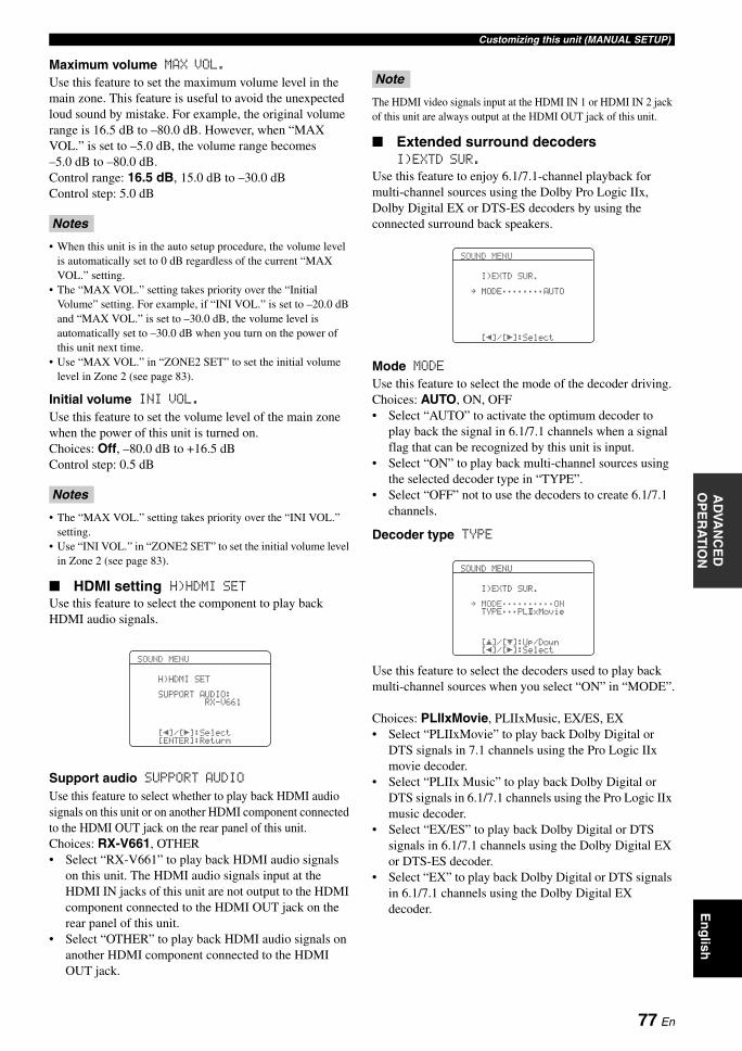
Customizing this unit (MANUAL SETUP)A
DVA
NC
ED
O
PE
RA
TIO
NE
ng
lish
Maximum volume MAX VOL.Use this feature to set the maximum volume level in the main zone. This feature is useful to avoid the unexpected loud sound by mistake. For example, the original volume range is 16.5 dB to –80.0 dB. However, when “MAX VOL.” is set to –5.0 dB, the volume range becomes –5.0 dB to –80.0 dB.Control range: 16.5 dB, 15.0 dB to –30.0 dBControl step: 5.0 dB
• When this unit is in the auto setup procedure, the volume level is automatically set to 0 dB regardless of the current “MAX VOL.” setting.
• The “MAX VOL.” setting takes priority over the “Initial Volume” setting. For example, if “INI VOL.” is set to –20.0 dB and “MAX VOL.” is set to –30.0 dB, the volume level is automatically set to –30.0 dB when you turn on the power of this unit next time.
• Use “MAX VOL.” in “ZONE2 SET” to set the initial volume level in Zone 2 (see page 83).
Initial volume INI VOL.Use this feature to set the volume level of the main zone when the power of this unit is turned on.Choices: Off, –80.0 dB to +16.5 dBControl step: 0.5 dB
• The “MAX VOL.” setting takes priority over the “INI VOL.” setting.
• Use “INI VOL.” in “ZONE2 SET” to set the initial volume level in Zone 2 (see page 83).
HDMI setting H)HDMI SETUse this feature to select the component to play back HDMI audio signals.
Support audio SUPPORT AUDIOUse this feature to select whether to play back HDMI audio signals on this unit or on another HDMI component connected to the HDMI OUT jack on the rear panel of this unit.Choices: RX-V661, OTHER• Select “RX-V661” to play back HDMI audio signals
on this unit. The HDMI audio signals input at the HDMI IN jacks of this unit are not output to the HDMI component connected to the HDMI OUT jack on the rear panel of this unit.
• Select “OTHER” to play back HDMI audio signals on another HDMI component connected to the HDMI OUT jack.
The HDMI video signals input at the HDMI IN 1 or HDMI IN 2 jack of this unit are always output at the HDMI OUT jack of this unit.
Extended surround decoders I)EXTD SUR.
Use this feature to enjoy 6.1/7.1-channel playback for multi-channel sources using the Dolby Pro Logic IIx, Dolby Digital EX or DTS-ES decoders by using the connected surround back speakers.
Mode MODEUse this feature to select the mode of the decoder driving.Choices: AUTO, ON, OFF• Select “AUTO” to activate the optimum decoder to
play back the signal in 6.1/7.1 channels when a signal flag that can be recognized by this unit is input.
• Select “ON” to play back multi-channel sources using the selected decoder type in “TYPE”.
• Select “OFF” not to use the decoders to create 6.1/7.1 channels.
Decoder type TYPE
Use this feature to select the decoders used to play back multi-channel sources when you select “ON” in “MODE”.
Choices: PLIIxMovie, PLIIxMusic, EX/ES, EX• Select “PLIIxMovie” to play back Dolby Digital or
DTS signals in 7.1 channels using the Pro Logic IIx movie decoder.
• Select “PLIIx Music” to play back Dolby Digital or DTS signals in 6.1/7.1 channels using the Pro Logic IIx music decoder.
• Select “EX/ES” to play back Dolby Digital or DTS signals in 6.1/7.1 channels using the Dolby Digital EX or DTS-ES decoder.
• Select “EX” to play back Dolby Digital or DTS signals in 6.1/7.1 channels using the Dolby Digital EX decoder.
Notes
Notes
SOUND MENU
H)HDMI SET
SUPPORT AUDIO:RX-V661
[ ]/[ ]:Selectp [[ENTER]:Return
Note
SOUND MENU
I)EXTD SUR.
. MODE;;;;;;;;AUTO
p [[ ]/[ ]:Select
SOUND MENU
I)EXTD SUR.
. MODE;;;;;;;;;;ONTYPE;;;PL xMovieII
[ ]/[ ]:Up/Down
p
pp [[ ]/[ ]:Select
77 En
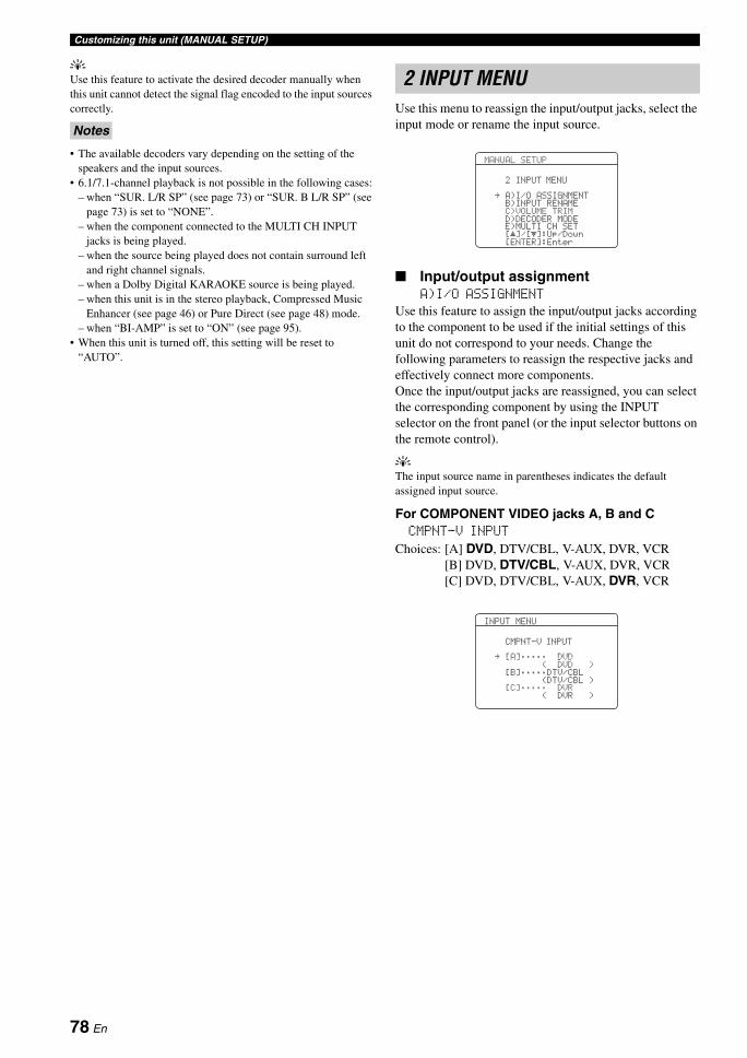
Customizing this unit (MANUAL SETUP)
yUse this feature to activate the desired decoder manually when this unit cannot detect the signal flag encoded to the input sources correctly.
• The available decoders vary depending on the setting of the speakers and the input sources.
• 6.1/7.1-channel playback is not possible in the following cases:– when “SUR. L/R SP” (see page 73) or “SUR. B L/R SP” (see
page 73) is set to “NONE”.– when the component connected to the MULTI CH INPUT
jacks is being played.– when the source being played does not contain surround left
and right channel signals.– when a Dolby Digital KARAOKE source is being played.– when this unit is in the stereo playback, Compressed Music
Enhancer (see page 46) or Pure Direct (see page 48) mode.– when “BI-AMP” is set to “ON” (see page 95).
• When this unit is turned off, this setting will be reset to “AUTO”.
Use this menu to reassign the input/output jacks, select the input mode or rename the input source.
Input/output assignment A)I/O ASSIGNMENT
Use this feature to assign the input/output jacks according to the component to be used if the initial settings of this unit do not correspond to your needs. Change the following parameters to reassign the respective jacks and effectively connect more components.Once the input/output jacks are reassigned, you can select the corresponding component by using the INPUT selector on the front panel (or the input selector buttons on the remote control).
yThe input source name in parentheses indicates the default assigned input source.
For COMPONENT VIDEO jacks A, B and C CMPNT-V INPUT
Choices: [A] DVD, DTV/CBL, V-AUX, DVR, VCR[B] DVD, DTV/CBL, V-AUX, DVR, VCR[C] DVD, DTV/CBL, V-AUX, DVR, VCR
Notes
2 INPUT MENU
MANUAL SETUP
2 INPUT MENU
. A)I/O ASSIGNMENTB)INPUT RENAMEC)VOLUME TRIMD)DECODER MODEE)MULTI CH SET[ ]/[ ]:Up/Down[ENTER]:Enter
pp
INPUT MENU
CMPNT-V INPUT
. [A];;;;; DVD( DVD )
[B];;;;;DTV/CBL(DTV/CBL))
[C];;;;; DVR( DVR )
78 En
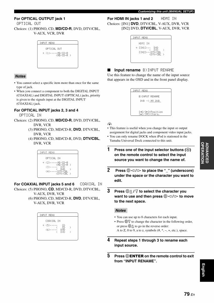
Customizing this unit (MANUAL SETUP)A
DVA
NC
ED
O
PE
RA
TIO
NE
ng
lish
For OPTICAL OUTPUT jack 1 OPTICAL OUT
Choices: (1) PHONO, CD, MD/CD-R, DVD, DTV/CBL, V-AUX, VCR, DVR
• You cannot select a specific item more than once for the same type of jack.
• When you connect a component to both the DIGITAL INPUT (COAXIAL) and DIGITAL INPUT (OPTICAL) jacks, priority is given to the signals input at the DIGITAL INPUT (COAXIAL) jack.
For OPTICAL INPUT jacks 2, 3 and 4 OPTICAL IN
Choices: (2) PHONO, CD, MD/CD-R, DVD, DTV/CBL, DVR, VCR
(3) PHONO, CD, MD/CD-R, DVD, DTV/CBL, DVR, VCR
(4) PHONO, CD, MD/CD-R, DVD, DTV/CBL, DVR, VCR
For COAXIAL INPUT jacks 5 and 6 COAXIAL IN
Choices: (5) PHONO, CD, MD/CD-R, DVD, DTV/CBL, V-AUX, DVR, VCR
(6) PHONO, CD, MD/CD-R, DVD, DTV/CBL, V-AUX, DVR, VCR
For HDMI IN jacks 1 and 2 HDMI IN
Choices: [IN1] DVD, DTV/CBL, V-AUX, DVR, VCR[IN2] DVD, DTV/CBL, V-AUX, DVR, VCR
Input rename B)INPUT RENAMEUse this feature to change the name of the input source that appears in the OSD and in the front panel display.
y• This feature is useful when you change the input or output
assignment for digital jacks and component video input jacks.• You can only rename DOCK when iPod is stationed in the
Yamaha Universal Dock connected to this unit.
1 Press one of the input selector buttons (A) on the remote control to select the input source you want to change the name of.
2 Press Dl / h to place the “_” (underscore) under the space or the character you want to edit.
3 Press Dk / n to select the character you want to use and then press Dl / h to move to the next space.
• You can use up to 8 characters for each input.• Press Dn to change the character in the following order,
or press Dk to go in the reverse order: A to Z, 0 to 9, a to z, symbols (#, *, –, +, etc.), space.
4 Repeat steps 1 through 3 to rename each input source.
5 Press DENTER on the remote control to exit from “INPUT RENAME”.
Notes
INPUT MENU
OPTICAL OUT
. (1);;;;;MD/CD-R(MD/CD-R )
INPUT MENU
OPTICAL IN
. (2);;;;;MD/CD-R(MD/CD-R )
(3);;;;; DVD( DVD )
(4);;;;;DTV/CBL(DTV/CBL )
INPUT MENU
COAXIAL IN
. (5);;;;; CD( CD )
(6);;;;; DVD( DVD )
(4);;;;;DTV/CBLTA
Notes
INPUT MENU
HDMI IN
. [IN1];;; DVD( DVD )
[IN2];;;DTV/CBL(DTV/CBL))
INPUT MENU
B)INPUT RENAME
DVD -> MY DVD
[ ]/[ ]:Position[ ]/[ ]:Chara.
p
p[[
79 En
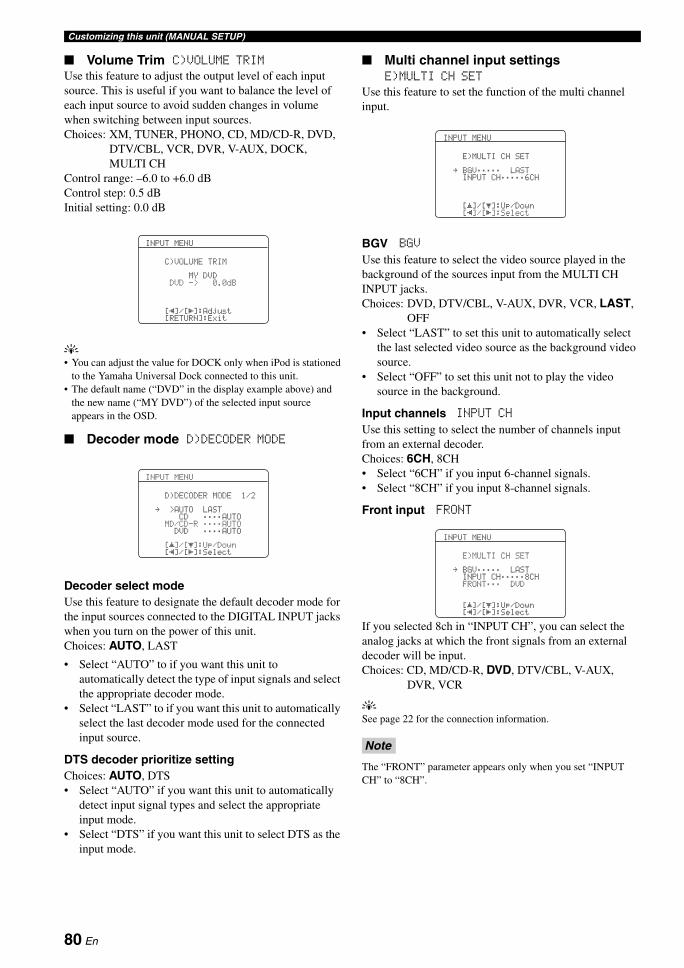
Customizing this unit (MANUAL SETUP)
Volume Trim C)VOLUME TRIMUse this feature to adjust the output level of each input source. This is useful if you want to balance the level of each input source to avoid sudden changes in volume when switching between input sources.Choices: XM, TUNER, PHONO, CD, MD/CD-R, DVD,
DTV/CBL, VCR, DVR, V-AUX, DOCK, MULTI CH
Control range: –6.0 to +6.0 dBControl step: 0.5 dBInitial setting: 0.0 dB
y• You can adjust the value for DOCK only when iPod is stationed
to the Yamaha Universal Dock connected to this unit.• The default name (“DVD” in the display example above) and
the new name (“MY DVD”) of the selected input source appears in the OSD.
Decoder mode D)DECODER MODE
Decoder select modeUse this feature to designate the default decoder mode for the input sources connected to the DIGITAL INPUT jacks when you turn on the power of this unit.Choices: AUTO, LAST
• Select “AUTO” to if you want this unit to automatically detect the type of input signals and select the appropriate decoder mode.
• Select “LAST” to if you want this unit to automatically select the last decoder mode used for the connected input source.
DTS decoder prioritize settingChoices: AUTO, DTS• Select “AUTO” if you want this unit to automatically
detect input signal types and select the appropriate input mode.
• Select “DTS” if you want this unit to select DTS as the input mode.
Multi channel input settings E)MULTI CH SET
Use this feature to set the function of the multi channel input.
BGV BGV
Use this feature to select the video source played in the background of the sources input from the MULTI CH INPUT jacks.Choices: DVD, DTV/CBL, V-AUX, DVR, VCR, LAST,
OFF• Select “LAST” to set this unit to automatically select
the last selected video source as the background video source.
• Select “OFF” to set this unit not to play the video source in the background.
Input channels INPUT CH
Use this setting to select the number of channels input from an external decoder.Choices: 6CH, 8CH• Select “6CH” if you input 6-channel signals.• Select “8CH” if you input 8-channel signals.
Front input FRONT
If you selected 8ch in “INPUT CH”, you can select the analog jacks at which the front signals from an external decoder will be input.Choices: CD, MD/CD-R, DVD, DTV/CBL, V-AUX,
DVR, VCR
ySee page 22 for the connection information.
The “FRONT” parameter appears only when you set “INPUT CH” to “8CH”.
INPUT MENU
C)VOLUME TRIM
MY DVDDVD -> 0.0dB
[ ]/[ ]:Adjust[RETURN]:Exit
[[
INPUT MENU
D)DECODER MODE 1/2
. >AUTO LASTCD ;;;;AUTO
MD/CD-R ;;;;AUTODVD ;;;;AUTO
[ ]/[ ]:Up/Down[ ]/[ ]:Select
p
p[[
Note
INPUT MENU
E)MULTI CH SET
. BGV;;;;; LASTINPUT CH;;;;;6CH
[ ]/[ ]:Up/Down[ ]/[ ]:Select
p
p[[
INPUT MENU
E)MULTI CH SET
. BGV;;;;; LASTINPUT CH;;;;;8CHFRONT;;; DVD
[ ]/[ ]:Up/Down[ ]/[ ]:Select
p
p[[
80 En
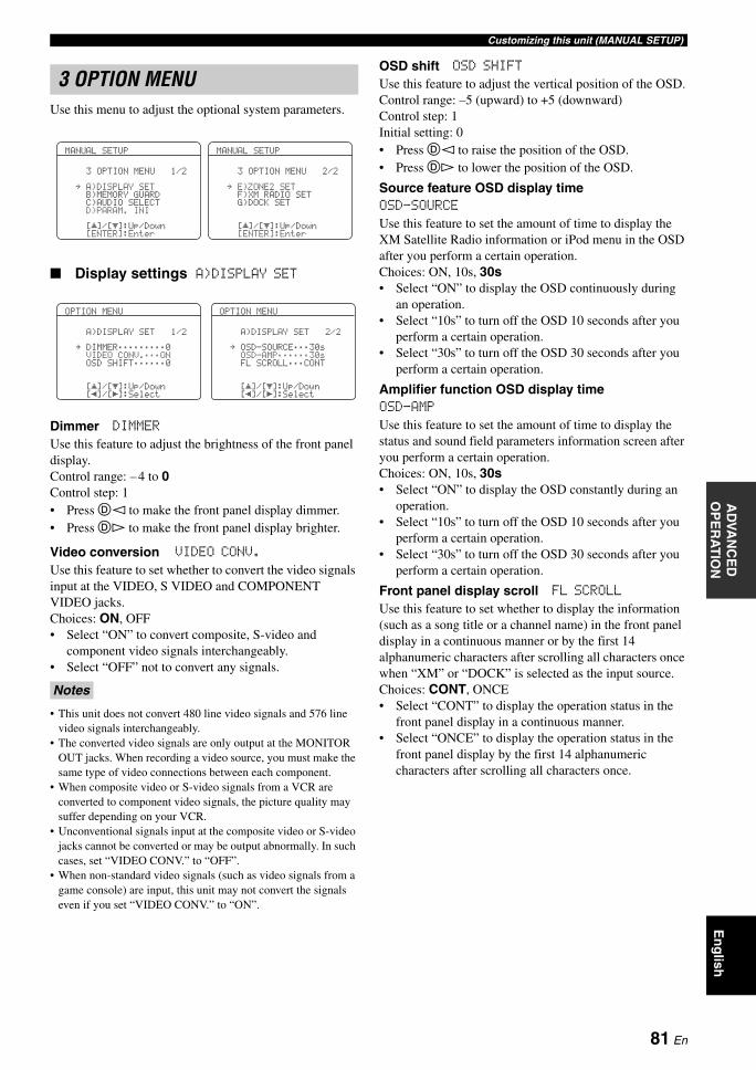
Customizing this unit (MANUAL SETUP)A
DVA
NC
ED
O
PE
RA
TIO
NE
ng
lish
Use this menu to adjust the optional system parameters.
Display settings A)DISPLAY SET
Dimmer DIMMERUse this feature to adjust the brightness of the front panel display.Control range: – 4 to 0Control step: 1• Press Dl to make the front panel display dimmer.• Press Dh to make the front panel display brighter.
Video conversion VIDEO CONV.
Use this feature to set whether to convert the video signals input at the VIDEO, S VIDEO and COMPONENT VIDEO jacks.Choices: ON, OFF• Select “ON” to convert composite, S-video and
component video signals interchangeably.• Select “OFF” not to convert any signals.
• This unit does not convert 480 line video signals and 576 line video signals interchangeably.
• The converted video signals are only output at the MONITOR OUT jacks. When recording a video source, you must make the same type of video connections between each component.
• When composite video or S-video signals from a VCR are converted to component video signals, the picture quality may suffer depending on your VCR.
• Unconventional signals input at the composite video or S-video jacks cannot be converted or may be output abnormally. In such cases, set “VIDEO CONV.” to “OFF”.
• When non-standard video signals (such as video signals from a game console) are input, this unit may not convert the signals even if you set “VIDEO CONV.” to “ON”.
OSD shift OSD SHIFTUse this feature to adjust the vertical position of the OSD.Control range: –5 (upward) to +5 (downward)Control step: 1Initial setting: 0• Press Dl to raise the position of the OSD.• Press Dh to lower the position of the OSD.
Source feature OSD display time OSD-SOURCE
Use this feature to set the amount of time to display the XM Satellite Radio information or iPod menu in the OSD after you perform a certain operation.Choices: ON, 10s, 30s• Select “ON” to display the OSD continuously during
an operation.• Select “10s” to turn off the OSD 10 seconds after you
perform a certain operation.• Select “30s” to turn off the OSD 30 seconds after you
perform a certain operation.
Amplifier function OSD display time OSD-AMP
Use this feature to set the amount of time to display the status and sound field parameters information screen after you perform a certain operation.Choices: ON, 10s, 30s• Select “ON” to display the OSD constantly during an
operation.• Select “10s” to turn off the OSD 10 seconds after you
perform a certain operation.• Select “30s” to turn off the OSD 30 seconds after you
perform a certain operation.
Front panel display scroll FL SCROLLUse this feature to set whether to display the information (such as a song title or a channel name) in the front panel display in a continuous manner or by the first 14 alphanumeric characters after scrolling all characters once when “XM” or “DOCK” is selected as the input source.Choices: CONT, ONCE• Select “CONT” to display the operation status in the
front panel display in a continuous manner.• Select “ONCE” to display the operation status in the
front panel display by the first 14 alphanumeric characters after scrolling all characters once.
3 OPTION MENU
Notes
MANUAL SETUP
3 OPTION MENU 1/2
p
p
. A)DISPLAY SETB)MEMORY GUARDC)AUDIO SELECTD)PARAM. INI
[ ]/[ ]:Up/Down[ENTER]:Enter
MANUAL SETUP
3 OPTION MENU 2/2
p
p
. E)ZONE2 SETF)XM RADIO SETG)DOCK SET
[ ]/[ ]:Up/Down[ENTER]:Enter
OPTION MENU
A)DISPLAY SET 1/2
. DIMMER;;;;;;;;;0VIDEO CONV.;;;ONOSD SHIFT;;;;;;0
[ ]/[ ]:Up/Down[ ]/[ ]:Select
p
p[[
OPTION MENU
A)DISPLAY SET 2/2
. OSD-SOURCE;;;30sOSD-AMP;;;;;;30sFL SCROLL;;;CONT
[ ]/[ ]:Up/Down[ ]/[ ]:Select
p
p[[
81 En
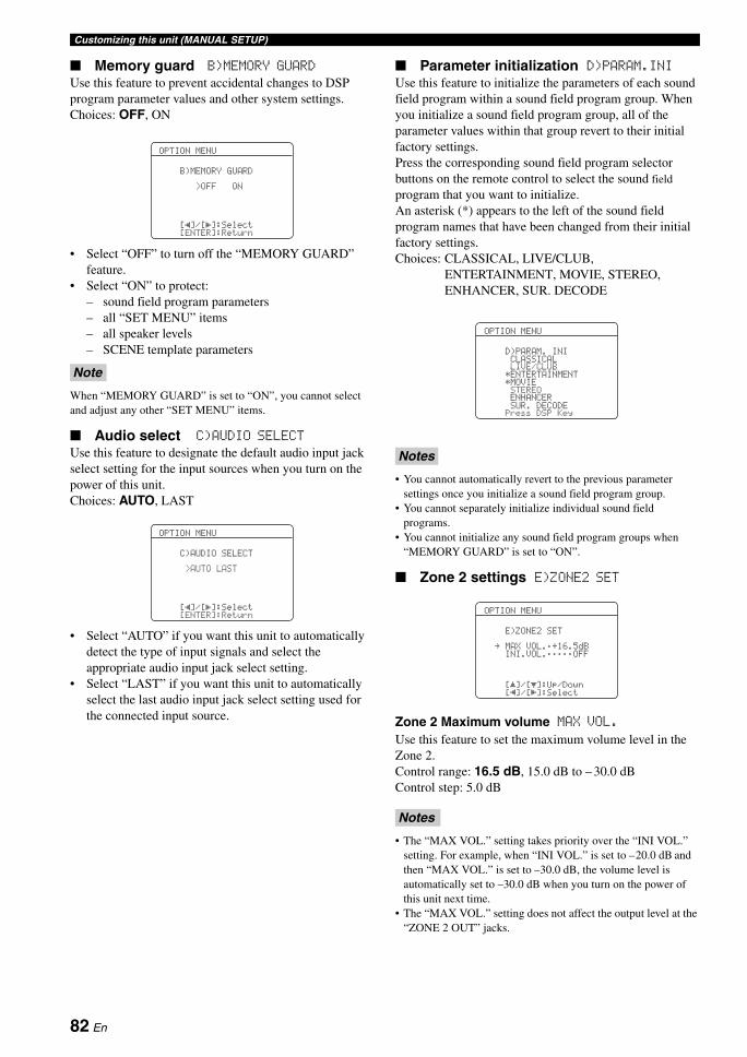
Customizing this unit (MANUAL SETUP)
Memory guard B)MEMORY GUARD
Use this feature to prevent accidental changes to DSP program parameter values and other system settings.Choices: OFF, ON
• Select “OFF” to turn off the “MEMORY GUARD” feature.
• Select “ON” to protect:– sound field program parameters– all “SET MENU” items– all speaker levels– SCENE template parameters
When “MEMORY GUARD” is set to “ON”, you cannot select and adjust any other “SET MENU” items.
Audio select C)AUDIO SELECT
Use this feature to designate the default audio input jack select setting for the input sources when you turn on the power of this unit.Choices: AUTO, LAST
• Select “AUTO” if you want this unit to automatically detect the type of input signals and select the appropriate audio input jack select setting.
• Select “LAST” if you want this unit to automatically select the last audio input jack select setting used for the connected input source.
Parameter initialization D)PARAM.INIUse this feature to initialize the parameters of each sound field program within a sound field program group. When you initialize a sound field program group, all of the parameter values within that group revert to their initial factory settings.Press the corresponding sound field program selector buttons on the remote control to select the sound field program that you want to initialize.An asterisk (*) appears to the left of the sound field program names that have been changed from their initial factory settings.Choices: CLASSICAL, LIVE/CLUB,
ENTERTAINMENT, MOVIE, STEREO, ENHANCER, SUR. DECODE
• You cannot automatically revert to the previous parameter settings once you initialize a sound field program group.
• You cannot separately initialize individual sound field programs.
• You cannot initialize any sound field program groups when “MEMORY GUARD” is set to “ON”.
Zone 2 settings E)ZONE2 SET
Zone 2 Maximum volume MAX VOL.Use this feature to set the maximum volume level in the Zone 2. Control range: 16.5 dB, 15.0 dB to – 30.0 dBControl step: 5.0 dB
• The “MAX VOL.” setting takes priority over the “INI VOL.” setting. For example, when “INI VOL.” is set to –20.0 dB and then “MAX VOL.” is set to –30.0 dB, the volume level is automatically set to –30.0 dB when you turn on the power of this unit next time.
• The “MAX VOL.” setting does not affect the output level at the “ZONE 2 OUT” jacks.
Note
OPTION MENU
B)MEMORY GUARD
>OFF ON
[ ]/[ ]:Select[ENTER]:Return
[[
OPTION MENU
C)AUDIO SELECT
>AUTO LAST
[ ]/[ ]:Select[ENTER]:Return
[[
Notes
Notes
OPTION MENU
D)PARAM. INICLASSICALLIVE/CLUB
*ENTERTAINMENT*MOVIESTEREO
SUR. DECODEENHANCER
Press DSP Key
OPTION MENU
E)ZONE2 SET
. MAX VOL.;+16.5dBINI.VOL.;;;;;OFF
[ ]/[ ]:Up/Down[ ]/[ ]:Select
p
p[[
82 En
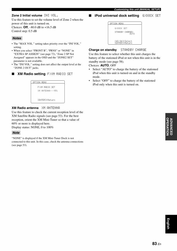
Customizing this unit (MANUAL SETUP)A
DVA
NC
ED
O
PE
RA
TIO
NE
ng
lish
Zone 2 Initial volume INI VOL.Use this feature to set the volume level of Zone 2 when the power of this unit is turned on.Choices: Off, –80.0 dB to +16.5 dBControl step: 0.5 dB
• The “MAX VOL.” setting takes priority over the “INI VOL.” setting.
• When you select “FRONT B”, “PRNS” or “NONE” in “EXTRA SP ASSIGN” (see page 72), “Zone 2 SP Not Assigned” appears in the OSD and the “ZONE2 SET” parameter is not available.
• The “INI VOL.” setting does not affect the output level at the “ZONE 2 OUT” jacks.
XM Radio setting F)XM RADIO SET
XM Radio antenna XM ANTENNAUse this feature to check the current reception level of the XM Satellite Radio signals (see page 53). For the best reception, orient the XM Mini-Tuner so that a value of 60% or more is displayed here.Display status: NONE, 0 to 100%
“NONE” is displayed if the XM Mini-Tuner Dock is not connected to this unit. In this case, check the antenna connections (see page 53).
iPod universal dock setting G)DOCK SET
Charge on standby STANDBY CHARGE
Use this feature to select whether this unit charges the battery of the stationed iPod or not when this unit is in the standby mode (see page 58).Choices: AUTO, OFF• Select “AUTO” to charge the battery of the stationed
iPod when this unit is turned on and in the standby mode.
• Select “OFF” to charge the battery of the stationed iPod only when this unit is turned on.
Notes
Note
OPTION MENU
F)XM RADIO SET
XM ANTENNA;;;95%
[ENTER]:Return
OPTION MENU
G)DOCK SET
STANDBY CHARGE:AUTO
[ ]/[ ]:Select[ENTER]:Return
[[
83 En
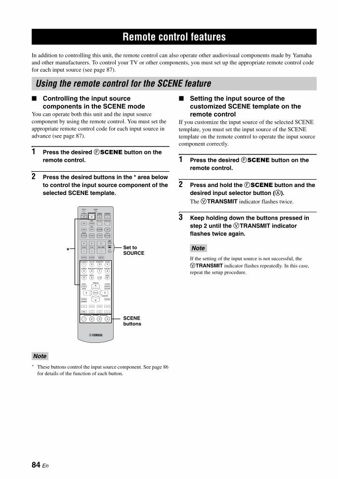
REMOTE CONTROL FEATURES
In addition to controlling this unit, the remote control can also operate other audiovisual components made by Yamaha and other manufacturers. To control your TV or other components, you must set up the appropriate remote control code for each input source (see page 87).
Controlling the input source components in the SCENE mode
You can operate both this unit and the input source component by using the remote control. You must set the appropriate remote control code for each input source in advance (see page 87).
1 Press the desired FSCENE button on the remote control.
2 Press the desired buttons in the * area below to control the input source component of the selected SCENE template.
* These buttons control the input source component. See page 86 for details of the function of each button.
Setting the input source of the customized SCENE template on the remote control
If you customize the input source of the selected SCENE template, you must set the input source of the SCENE template on the remote control to operate the input source component correctly.
1 Press the desired FSCENE button on the remote control.
2 Press and hold the FSCENE button and the desired input selector button (A).The VTRANSMIT indicator flashes twice.
3 Keep holding down the buttons pressed in step 2 until the VTRANSMIT indicator flashes twice again.
If the setting of the input source is not successful, the VTRANSMIT indicator flashes repeatedly. In this case, repeat the setup procedure.
Remote control features
Using the remote control for the SCENE feature
Note
5 6 7 8
9 0 +10 ENT
1 2 3 4
MENUTITLE
SET MENULEVEL
CLASSICAL LIVE/CLUB ENTERTAIN MOVIE
STEREO ENHANCER STRAIGHT PURE DIRECT
SUR. DECODE NIGHT SLEEP
DISPLAYRETURN
BAND SRCH MODE
XM MEMORY
REC
SCENE
A-E/CAT.
ENTER
PRESET/CH
VOLUMETV VOL TV CH
TV MUTE TV INPUT MUTE
AMP
SOURCE
TV
CD CD-R
DVD DTV
MD MULTI CH IN AUDIO SEL
CBL
TUNER
V-AUX
DOCK
DVR VCR
XM
PHONO
STANDBY POWERPOWERPOWER
AVTV
TRANSMITCODE SET
1 2 3 4
* Set to SOURCE
SCENE buttons
Note
84 En
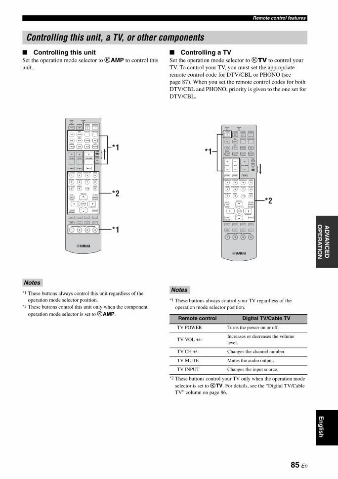
Remote control featuresA
DVA
NC
ED
O
PE
RA
TIO
NE
ng
lish
Controlling this unitSet the operation mode selector to KAMP to control this unit.
*1 These buttons always control this unit regardless of the operation mode selector position.
*2 These buttons control this unit only when the component operation mode selector is set to KAMP.
Controlling a TVSet the operation mode selector to KTV to control your TV. To control your TV, you must set the appropriate remote control code for DTV/CBL or PHONO (see page 87). When you set the remote control codes for both DTV/CBL and PHONO, priority is given to the one set for DTV/CBL.
*1 These buttons always control your TV regardless of the operation mode selector position.
*2 These buttons control your TV only when the operation mode selector is set to KTV. For details, see the “Digital TV/Cable TV” column on page 86.
Controlling this unit, a TV, or other components
Notes
5 6 7 8
9 0 +10 ENT
1 2 3 4
MENUTITLE
SET MENULEVEL
CLASSICAL LIVE/CLUB ENTERTAIN MOVIE
STEREO ENHANCER STRAIGHT PURE DIRECT
SUR. DECODE NIGHT SLEEP
DISPLAYRETURN
BAND SRCH MODE
XM MEMORY
REC
SCENE
A-E/CAT.
ENTER
PRESET/CH
VOLUMETV VOL TV CH
TV MUTE TV INPUT MUTE
AMP
SOURCE
TV
CD CD-R
DVD DTV
MD MULTI CH IN AUDIO SEL
CBL
TUNER
V-AUX
DOCK
DVR VCR
XM
PHONO
STANDBY POWERPOWERPOWER
AVTV
TRANSMITCODE SET
1 2 3 4
*1
*2
*1
Notes
Remote control Digital TV/Cable TV
TV POWER Turns the power on or off.
TV VOL +/–Increases or decreases the volume level.
TV CH +/– Changes the channel number.
TV MUTE Mutes the audio output.
TV INPUT Changes the input source.
5 6 7 8
9 0 +10 ENT
1 2 3 4
MENUTITLE
SET MENULEVEL
CLASSICAL LIVE/CLUB ENTERTAIN MOVIE
STEREO ENHANCER STRAIGHT PURE DIRECT
SUR. DECODE NIGHT SLEEP
DISPLAYRETURN
BAND SRCH MODE
XM MEMORY
REC
SCENE
A-E/CAT.
ENTER
PRESET/CH
VOLUMETV VOL TV CH
TV MUTE TV INPUT MUTE
AMP
SOURCE
TV
CD CD-R
DVD DTV
MD MULTI CH IN AUDIO SEL
CBL
TUNER
V-AUX
DOCK
DVR VCR
XM
PHONO
STANDBY POWERPOWERPOWER
AVTV
TRANSMITCODE SET
1 2 3 4
*1
*2
85 En
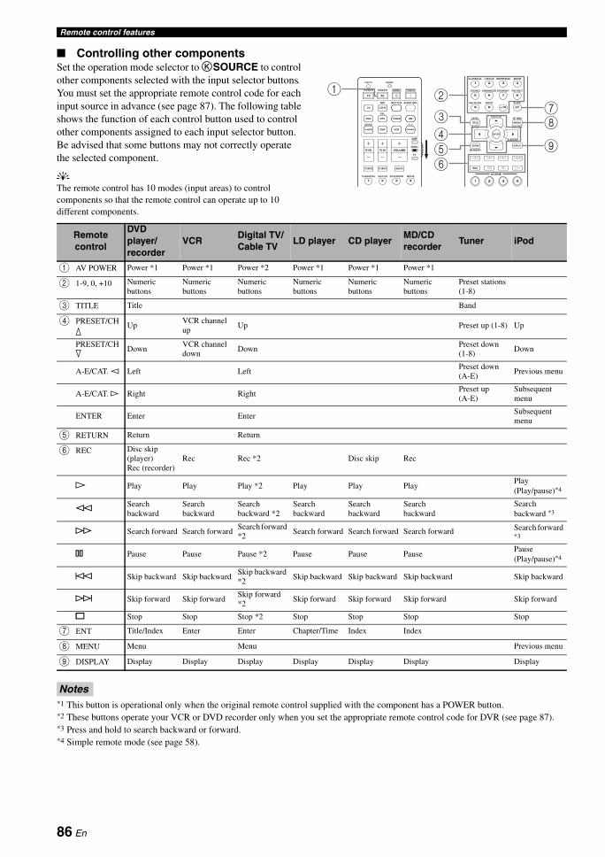
Remote control features
Controlling other componentsSet the operation mode selector to KSOURCE to control other components selected with the input selector buttons. You must set the appropriate remote control code for each input source in advance (see page 87). The following table shows the function of each control button used to control other components assigned to each input selector button. Be advised that some buttons may not correctly operate the selected component.
yThe remote control has 10 modes (input areas) to control components so that the remote control can operate up to 10 different components.
*1 This button is operational only when the original remote control supplied with the component has a POWER button.*2 These buttons operate your VCR or DVD recorder only when you set the appropriate remote control code for DVR (see page 87).*3 Press and hold to search backward or forward.*4 Simple remote mode (see page 58).
1 2 3 4
CLASSICAL LIVE/CLUB ENTERTAIN MOVIE
VOLUMETV VOL TV CH
TV MUTE TV INPUT MUTE
AMP
SOURCE
TV
CD CD-R
DVD DTV
MD MULTI CH IN AUDIO SEL
CBL
TUNER
V-AUX
DOCK
DVR VCR
XM
PHONO
STANDBY POWERPOWERPOWER
AVTV
TRANSMITCODE SET
5 6 7 8
9 0 +10 ENT
1 2 3 4
MENUTITLE
SET MENULEVEL
CLASSICAL LIVE/CLUB ENTERTAIN MOVIE
STEREO ENHANCER STRAIGHT PURE DIRECT
SUR. DECODE NIGHT SLEEP
DISPLAYRETURN
BAND SRCH MODE
XM MEMORY
REC
SCENE
A-E/CAT.
ENTER
PRESET/CH
1 2 3 4
2
8
9
73
4
65
1
Remote control
DVD player/recorder
VCRDigital TV/Cable TV
LD player CD playerMD/CD recorder
Tuner iPod
1 AV POWER Power *1 Power *1 Power *2 Power *1 Power *1 Power *1
2 1-9, 0, +10 Numeric buttons
Numeric buttons
Numeric buttons
Numeric buttons
Numeric buttons
Numeric buttons
Preset stations (1-8)
3 TITLE Title Band
4 PRESET/CH k
UpVCR channel up
Up Preset up (1-8) Up
PRESET/CH n
DownVCR channel down
DownPreset down (1-8)
Down
A-E/CAT. l Left LeftPreset down (A-E)
Previous menu
A-E/CAT. h Right RightPreset up (A-E)
Subsequent menu
ENTER Enter EnterSubsequent menu
5 RETURN Return Return
6 REC Disc skip (player)Rec (recorder)
Rec Rec *2 Disc skip Rec
p Play Play Play *2 Play Play PlayPlay (Play/pause)*4
wSearch backward
Search backward
Search backward *2
Search backward
Search backward
Search backward
Search backward *3
f Search forward Search forwardSearch forward *2
Search forward Search forward Search forward Search forward *3
e Pause Pause Pause *2 Pause Pause PausePause (Play/pause)*4
b Skip backward Skip backwardSkip backward *2
Skip backward Skip backward Skip backward Skip backward
a Skip forward Skip forwardSkip forward *2
Skip forward Skip forward Skip forward Skip forward
s Stop Stop Stop *2 Stop Stop Stop Stop
7 ENT Title/Index Enter Enter Chapter/Time Index Index
8 MENU Menu Menu Previous menu
9 DISPLAY Display Display Display Display Display Display Display
Notes
86 En
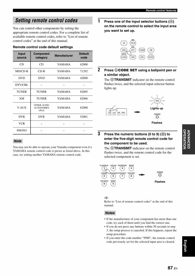
Remote control featuresA
DVA
NC
ED
O
PE
RA
TIO
NE
ng
lish
You can control other components by setting the appropriate remote control codes. For a complete list of available remote control codes, refer to “List of remote control codes” at the end of this manual.
Remote control code default settings
You may not be able to operate your Yamaha component even if a YAMAHA remote control code is preset as listed above. In this case, try setting another YAMAHA remote control code.
1 Press one of the input selector buttons (A) on the remote control to select the input area you want to set up.
2 Press UCODE SET using a ballpoint pen or a similar object.The VTRANSMIT indicator on the remote control flashes twice, and the selected input selector button lights up.
3 Press the numeric buttons (0 to 9) (B) to enter the five-digit remote control code for the component to be used.The VTRANSMIT indicator on the remote control flashes twice, and the remote control code for the selected component is set.
yRefer to “List of remote control codes” at the end of this manual.
• If the manufacturer of your component has more than one code, try each of them until you find the correct one.
• If you do not press any buttons within 30 seconds in step 3, the setup process is canceled. If this happens, repeat the setup procedure.
• If you enter the code number “9980”, the remote control code previously set for the selected input area is cleared.
Setting remote control codes
Input source
Component category
ManufacturerDefault code
CD CD YAMAHA 62000
MD/CD-R CD-R YAMAHA 71292
DVD DVD YAMAHA 42000
DTV/CBL – – –
TUNER TUNER YAMAHA 82005
XM TUNER YAMAHA 82006
V-AUXOTHER AUDIO ACCESSORIES
(iPod)YAMAHA 82000
DVR DVR YAMAHA 52001
VCR – – –
PHONO – – –
Note
Notes
CD CD-R
DVD DTV
MD
CBL
TUNER
V-AUX
DOCK
DVR VCR
XM
PHONO
TRANSMITSTANDBY POWERPOWERPOWER
AVTV
TRANSMITCODE SET
DVD
Flashes
Lights up
TRANSMIT
5 6 7 8
9 0
1 2 3 4
CLASSICAL LIVE/CLUB ENTERTAIN MOVIE
STEREO ENHANCER STRAIGHT PURE DIRECT
SUR. DECODE NIGHT Flashes
87 En
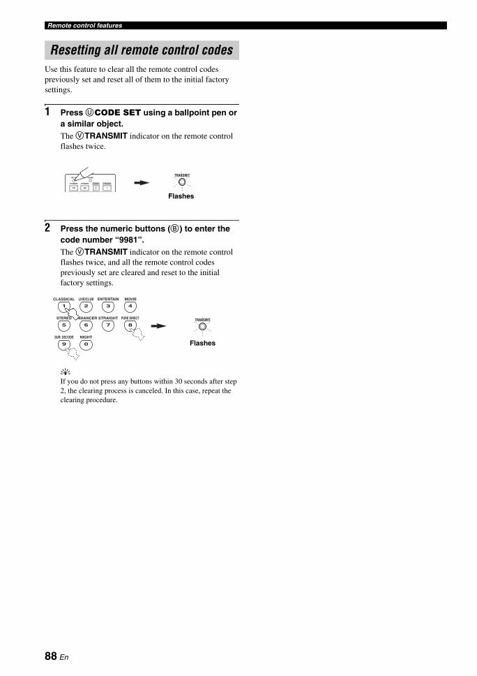
Remote control features
Use this feature to clear all the remote control codes previously set and reset all of them to the initial factory settings.
1 Press UCODE SET using a ballpoint pen or a similar object.The VTRANSMIT indicator on the remote control flashes twice.
2 Press the numeric buttons (B) to enter the code number “9981”.The VTRANSMIT indicator on the remote control flashes twice, and all the remote control codes previously set are cleared and reset to the initial factory settings.
yIf you do not press any buttons within 30 seconds after step 2, the clearing process is canceled. In this case, repeat the clearing procedure.
Resetting all remote control codes
TRANSMIT
STANDBY POWERPOWERPOWER
AVTV
TRANSMITCODE SET
Flashes
TRANSMIT5 6 7 8
9 0
1 2 3 4
CLASSICAL LIVE/CLUB ENTERTAIN MOVIE
STEREO ENHANCER STRAIGHT PURE DIRECT
SUR. DECODE NIGHT
Flashes
88 En
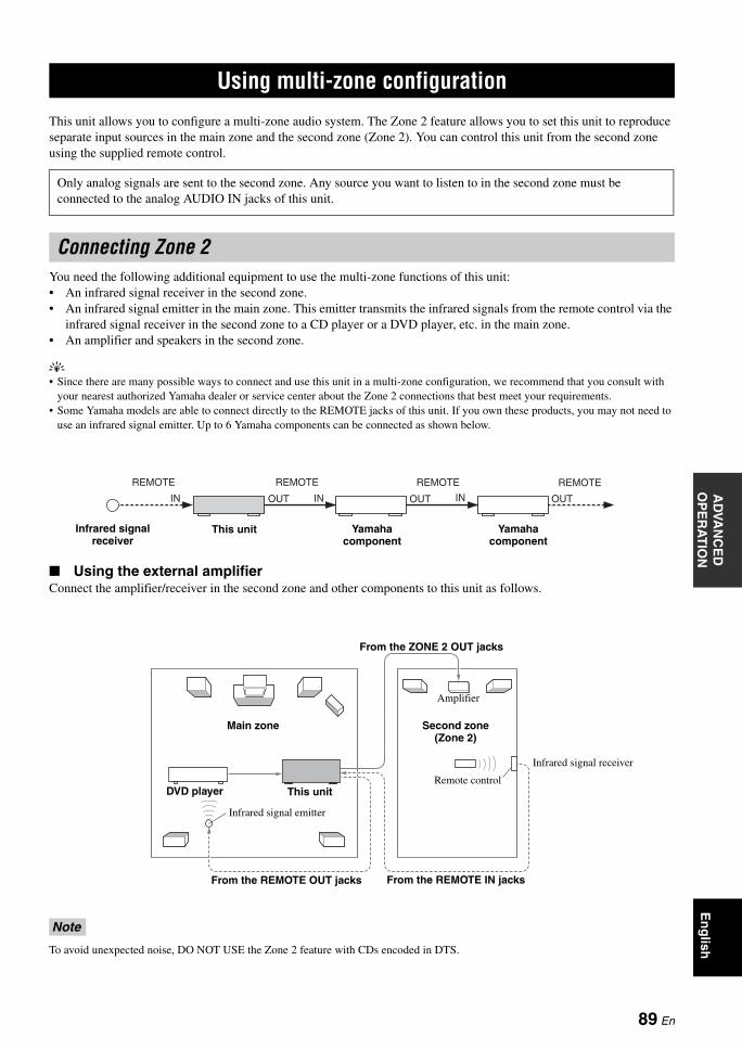
USING MULTI-ZONE CONFIGURATIONA
DVA
NC
ED
O
PE
RA
TIO
NE
ng
lish
This unit allows you to configure a multi-zone audio system. The Zone 2 feature allows you to set this unit to reproduce separate input sources in the main zone and the second zone (Zone 2). You can control this unit from the second zone using the supplied remote control.
You need the following additional equipment to use the multi-zone functions of this unit:• An infrared signal receiver in the second zone.• An infrared signal emitter in the main zone. This emitter transmits the infrared signals from the remote control via the
infrared signal receiver in the second zone to a CD player or a DVD player, etc. in the main zone.• An amplifier and speakers in the second zone.
y• Since there are many possible ways to connect and use this unit in a multi-zone configuration, we recommend that you consult with
your nearest authorized Yamaha dealer or service center about the Zone 2 connections that best meet your requirements.• Some Yamaha models are able to connect directly to the REMOTE jacks of this unit. If you own these products, you may not need to
use an infrared signal emitter. Up to 6 Yamaha components can be connected as shown below.
Using the external amplifierConnect the amplifier/receiver in the second zone and other components to this unit as follows.
To avoid unexpected noise, DO NOT USE the Zone 2 feature with CDs encoded in DTS.
Using multi-zone configuration
Only analog signals are sent to the second zone. Any source you want to listen to in the second zone must be connected to the analog AUDIO IN jacks of this unit.
Connecting Zone 2
Note
OUTOUT IN
REMOTE
IN
REMOTE
OUT IN
REMOTE REMOTE
This unit Yamaha component
Yamaha component
Infrared signal receiver
Infrared signal emitter
DVD player
Amplifier
Remote control
Infrared signal receiver
Second zone(Zone 2)
Main zone
This unit
From the ZONE 2 OUT jacks
From the REMOTE OUT jacks From the REMOTE IN jacks
89 En
Using multi-zone configuration
Using the internal amplifier of this unit
Connect the speakers in the second zone to the EXTRA SP speaker terminals and then set the “EXTRA SP ASSIGN” to “ZONE2” (see page 72).
y• You can use the FRONT B speakers as the front speaker system of another zone. Set “EXTRA SP ASSIGN” to “FRONT B” and then
“FRONT B” to “ZONE B” (see page 72).• When you use the internal amplifiers for the Zone 2 speakers, you can adjust the volume level and set the initial volume level and
maximum volume level of the Zone 2 speakers (see page 82).
You can select and control Zone 2 by using the control buttons on the front panel or on the remote control. The available operations are as follows:• Selecting the input source of Zone 2• Tuning into FM or AM when “TUNER” is selected as
the input source of Zone 2 (see page 50)• Tuning into XM Satellite Radio when “XM” is selected
as the input source of Zone 2 (see page 53) (U.S.A. and Canada models only)
• Enjoying music stored on your iPod stationed in a Yamaha iPod universal dock (such as YDS-10 sold separately) connected to the DOCK terminal of this unit when “V-AUX” is selected as the input source (see page 58)
You must complete each step while the ZONE2 indicator is flashing in the front panel display. Otherwise, the Zone 2 mode is automatically canceled and this unit returns to the normal operation mode. In this case, repeat the Zone 2 selection procedure.
Controlling Zone 2 with the front panel
Turning on Zone 2
Press 8ZONE 2 ON/OFF to turn on Zone 2.
y8ZONE 2 ON/OFF is operational only when BMASTER ON/OFF on the front panel is pressed inward to the ON position. Once BMASTER ON/OFF on the front panel is pressed inward to the ON position, you can also press HPOWER or GSTANDBY on the remote control to turn on the main zone and Zone 2 or set them to the standby mode.
Activating the Zone 2 operation mode
Press 9ZONE CONTROL to control Zone 2.The ZONE2 indicator flashes in the front panel display for approximately 10 seconds.
Important safety notice
The EXTRA SP speaker terminals of this Receiver should not be connected to a Passive Loudspeaker Selector Box or more than one loudspeaker per channel.Connection to a Passive Loudspeaker Selector Box or multiple speakers per channel could create an abnormally low impedance load resulting in amplifier damage. See this owner’s manual for correct usage.Compliance with minimum speaker impedance information for all channels must be maintained at all times. This information is found on the back panel of your Receiver.
Controlling Zone 2
FRONT B/ZONE2/PRESENCEEXTRA SP LR
Second zone(Zone 2) This unit
Main zone
Note
ZONE2
Flashes
90 En
Using multi-zone configurationA
DVA
NC
ED
O
PE
RA
TIO
NE
ng
lish
Operating Zone 2
Rotate the IINPUT selector to select the desired input source while the ZONE2 indicator is flashing in the front panel display.
• Select “TUNER” as the input source to use the TUNER features in Zone 2. For details about the TUNER operations, see “FM/AM tuning” on page 50.
• Select “XM” as the input source to use the XM Satellite Radio features in Zone 2. For details about the XM Satellite Radio operations, see “XM Satellite Radio tuning” on page 53.
• Select “V-AUX” as the input source to use iPod features in Zone 2. For details about the iPod operations, see “Using iPod™” on page 58.
Set Zone 2 to the standby mode
Press 8ZONE 2 ON/OFF to set Zone 2 to the standby mode.
Setting the remote control to the Zone 2 mode
The remote control is originally set to the main mode to control the main zone. To control Zone 2 with the remote control, you must first set the remote control to the Zone 2 mode.
1 Press UCODE SET using a ballpoint pen or a similar object.The VTRANSMIT indicator on the remote control flashes twice.
2 Press the numeric buttons (B) to enter the code number “9992”.
Controlling Zone 2 with the remote control
Turning on Zone 2
Press and hold HPOWER or GSTANDBY and then press A to set the remote control to the Zone 2 mode.• Press HPOWER when the main zone is turned on.
• Press GSTANDBY when the main zone is turned off.
The VTRANSMIT indicator on the remote control lights up while the remote control is set to the Zone 2 mode.
• When the remote control is set to the Zone 2 mode, HPOWER, GSTANDBY, JVOLUME +/–, LMUTE, and the input selector buttons are set to control Zone 2. However, the rest of the remote control buttons remain in the main mode.
• The remote control automatically exits from the Zone 2 mode in the following cases:– when you do not make any operations within 10 seconds after
the remote control is set to the Zone 2 mode.– when you press a remote control button other than HPOWER, GSTANDBY, JVOLUME +/–, LMUTE, and the input selector buttons.
Activating the Zone 2 operation mode
Press HPOWER to turn on Zone 2.
Operating Zone 2
Press one of the input selector buttons (A) to select the desired input source of Zone 2.
Setting Zone 2 to the standby mode
Press GSTANDBY to set Zone 2 to the standby mode.
Operate the following operations after activating the Zone 2 operation mode.
TRANSMIT
STANDBY POWERPOWERPOWER
AVTV
TRANSMITCODE SET
Flashes
TRANSMIT5 6 7 8
9 0
1 2 3 4
CLASSICAL LIVE/CLUB ENTERTAIN MOVIE
STEREO ENHANCER STRAIGHT PURE DIRECT
SUR. DECODE NIGHT
Flashes
Notes
POWER
STANDBY
PHONO
TRANSMIT
Lights up
While holding down
or
91 En
ADVANCED SETUP
This unit has additional menus that are displayed in the front panel display. The advanced setup menu offers additional operations to adjust and customize the way this unit operates. Change the initial settings (indicated in bold under each parameter) to reflect the needs of your listening environment.
• The settings you make are reflected next time you press BMASTER ON/OFF inward to the ON position to turn on this unit (see page 25).
• Only BMASTER ON/OFF, CTONE CONTROL and the DPROGRAM selector are effective while you are using the advanced setup menu.
• No other operations can be made while you are using the advanced setup menu.• The advanced setup menu is only available in the front panel display.
1 Press BMASTER ON/OFF on the front panel to release it outward to the OFF position to turn off this unit.
2 Press and hold CTONE CONTROL and then press BMASTER ON/OFF inward to the ON position to turn on this unit.This unit turns on, and the advanced setup menu appears in the front panel display.
3 Rotate the DPROGRAM selector to select the parameter you want to adjust.The name of the selected parameter appears in the front panel display.See page 93 for a complete list of available parameters.
4 Press CTONE CONTROL repeatedly to change the selected parameter setting.
5 Press BMASTER ON/OFF to release it outward to the OFF position to save the new setting and turn off this unit.
yThe settings you made are reflected next time you turn on this unit.
Advanced setup
Notes
Using the advanced setup
TONE CONTROL MASTER
ON OFF
While holding down
SPIMP.-8MIN
Currently selectedparameter setting
Currently selectedparameter
92 En
Advanced setupA
DVA
NC
ED
O
PE
RA
TIO
NE
ng
lish
Speaker impedance SP IMP.
Use this feature to set the speaker impedance of this unit so that it matches that of your speakers.Choices: 8Ω MIN, 6Ω MIN• Select “8Ω MIN” to set the speaker impedance to 8 Ω .• Select “6Ω MIN” to set the speaker impedance to 6 Ω .
* The Canada model cannot use two separate speaker systems (A and B) simultaneously when “SP IMP.” is set to “8Ω MIN”.
User presets PRESET
Use this feature to reset all the parameters of this unit to the initial factory settings (see page 103).Choices: CANCEL, RESET• Select “CANCEL” not to reset any parameters of this
unit.• Select “RESET” to reset the parameters of this unit.
• This setting completely resets all the parameters of this unit including the “SET MENU” parameters.
• The initial factory settings are activated next time you turn on this unit.
Remote control AMP ID REMOTE AMPUse this feature to set the AMP ID of this unit for remote control recognition. This feature is useful when you operate this unit and the other Yamaha receivers/amplifiers in the same room separately.Choices: ID1, ID2• Select “ID1” when the remote control AMP ID code is
set to “00001”.• Select “ID2” when the remote control AMP ID code is
set to “00002”.
Setting remote control AMP ID codesYou need to set the remote control AMP ID code for the remote control.
1 Press UCODE SET using a ballpoint pen or a similar object.The VTRANSMIT indicator on the remote control flashes twice.
2 Press the numeric buttons (B) to enter the code number “00001” or “00002”.The VTRANSMIT indicator on the remote control flashes twice, and the AMP ID code is changed.
*1 The remote control setting*2 The setting of this unit
See page 92 for the operation of the advanced setup.
SP IMP. Speaker Impedance level
8Ω MIN
Front
If you use one set (A or B), the impedance of each speaker must be 8 Ω or higher.
If you use two sets (A and B), the impedance of each speaker must be 16 Ω or higher.*
Center
The impedance of each speaker must be 8 Ω or higher.
Surround
Surround back
6Ω MIN
Front
If you use one set (A or B), the impedance of each speaker must be 4 Ω or higher.
If you use two sets (A and B), the impedance of each speaker must be 8 Ω or higher.
Center
The impedance of each speaker must be 6 Ω or higher.
Surround
Surround back
Notes
AMP ID code *1
FunctionRemote
control AMP ID *2
00001(initial setting)
To operate this unit using the default code.
ID1 (initial setting)
00002To operate this unit using an alternative code.
ID2
TRANSMIT
STANDBY POWERPOWERPOWER
AVTV
TRANSMITCODE SET
Flashes
TRANSMIT5 6 7 8
9 0
1 2 3 4
CLASSICAL LIVE/CLUB ENTERTAIN MOVIE
STEREO ENHANCER STRAIGHT PURE DIRECT
SUR. DECODE NIGHT
Flashes
93 En
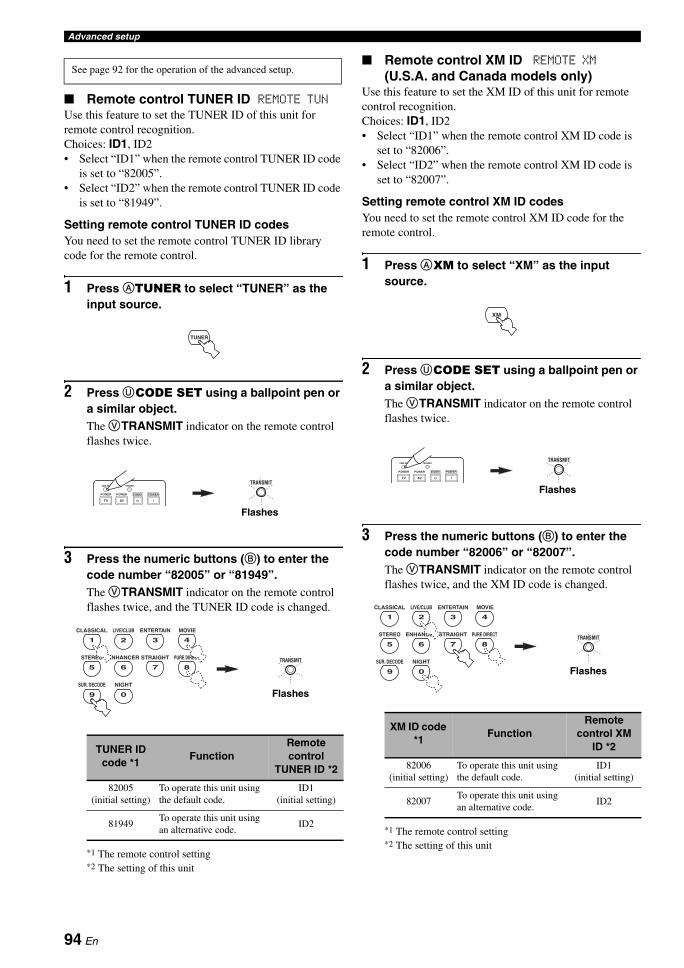
Advanced setup
Remote control TUNER ID REMOTE TUNUse this feature to set the TUNER ID of this unit for remote control recognition.Choices: ID1, ID2• Select “ID1” when the remote control TUNER ID code
is set to “82005”.• Select “ID2” when the remote control TUNER ID code
is set to “81949”.
Setting remote control TUNER ID codesYou need to set the remote control TUNER ID library code for the remote control.
1 Press ATUNER to select “TUNER” as the input source.
2 Press UCODE SET using a ballpoint pen or a similar object.The VTRANSMIT indicator on the remote control flashes twice.
3 Press the numeric buttons (B) to enter the code number “82005” or “81949”.The VTRANSMIT indicator on the remote control flashes twice, and the TUNER ID code is changed.
*1 The remote control setting*2 The setting of this unit
Remote control XM ID REMOTE XM
(U.S.A. and Canada models only)Use this feature to set the XM ID of this unit for remote control recognition.Choices: ID1, ID2• Select “ID1” when the remote control XM ID code is
set to “82006”.• Select “ID2” when the remote control XM ID code is
set to “82007”.
Setting remote control XM ID codesYou need to set the remote control XM ID code for the remote control.
1 Press AXM to select “XM” as the input source.
2 Press UCODE SET using a ballpoint pen or a similar object.The VTRANSMIT indicator on the remote control flashes twice.
3 Press the numeric buttons (B) to enter the code number “82006” or “82007”.The VTRANSMIT indicator on the remote control flashes twice, and the XM ID code is changed.
*1 The remote control setting*2 The setting of this unit
See page 92 for the operation of the advanced setup.
TUNER ID code *1
FunctionRemote control
TUNER ID *2
82005(initial setting)
To operate this unit using the default code.
ID1 (initial setting)
81949To operate this unit using an alternative code.
ID2
TUNER
TRANSMIT
STANDBY POWERPOWERPOWER
AVTV
TRANSMITCODE SET
Flashes
TRANSMIT5 6 7 8
9 0
1 2 3 4
CLASSICAL LIVE/CLUB ENTERTAIN MOVIE
STEREO ENHANCER STRAIGHT PURE DIRECT
SUR. DECODE NIGHT
Flashes
XM ID code *1
FunctionRemote
control XM ID *2
82006(initial setting)
To operate this unit using the default code.
ID1 (initial setting)
82007To operate this unit using an alternative code.
ID2
XM
TRANSMIT
STANDBY POWERPOWERPOWER
AVTV
TRANSMITCODE SET
Flashes
TRANSMIT5 6 7 8
9 0
1 2 3 4
CLASSICAL LIVE/CLUB ENTERTAIN MOVIE
STEREO ENHANCER STRAIGHT PURE DIRECT
SUR. DECODE NIGHT
Flashes
94 En
Advanced setupA
DVA
NC
ED
O
PE
RA
TIO
NE
ng
lish
SCENE IR code setting SCENE IRUse this feature to output the remote control signals at the REMOTE OUT jack automatically when this unit is in the SCENE mode.Choices: ON, OFF• Select “ON” when the component connected to the
REMOTE OUT jack is the Yamaha component and has the capability of the SCENE control signals. This unit automatically sends the remote control signals to the component.
• Select “OFF” when the component connected to the REMOTE OUT jack is not the Yamaha component and does not have the capability of the SCENE control signals.
If noises are output when you operate the SCENE function, set “SCENE IR” to “OFF”.
Bi-amplifier setting BI-AMPUse this feature to activate or deactivate the bi-amplifier function (see page 14).Choices: ON, OFF• Select “ON” if you want to activate the bi-amplifier
function. “SUR. B L/R SP” is set to NONE” automatically, and this unit outputs the front channel audio signals at the SURROUND BACK speaker terminals.
• Select “OFF” if you want to deactivate the bi-amplifier function.
When “BI-AMP” is set to “ON”, you can only select “FRONT B” or “NONE” in “EXTRA SP ASSIGN” (see page 72).
Tuner frequency step TU
(Asia and General models only)Use this feature to set the tuner frequency step according to the frequency spacing in your area.Choices: AM10/FM100, AM9/FM50• Select “AM10/FM100” for North, Central and South
America.• Select “AM9/FM50” for all other areas.
See page 92 for the operation of the advanced setup.
Note
Note
95 En
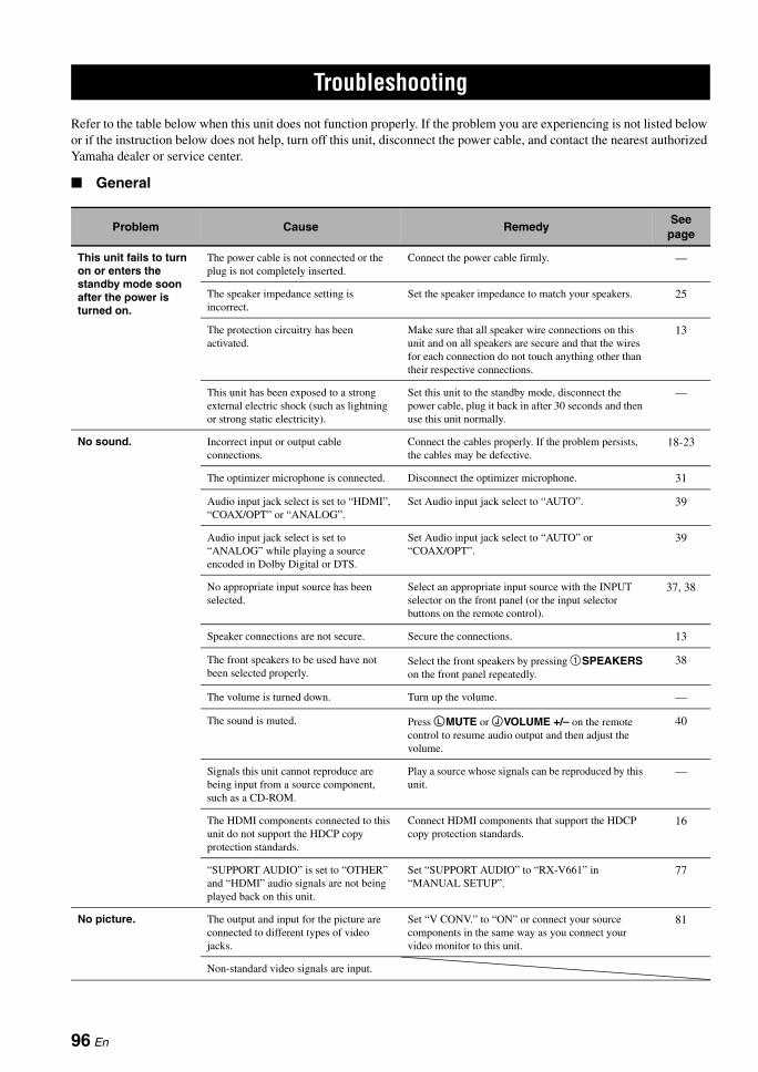
TROUBLESHOOTING
Refer to the table below when this unit does not function properly. If the problem you are experiencing is not listed below or if the instruction below does not help, turn off this unit, disconnect the power cable, and contact the nearest authorized Yamaha dealer or service center.
General
Troubleshooting
Problem Cause RemedySee
page
This unit fails to turn on or enters the standby mode soon after the power is turned on.
The power cable is not connected or the plug is not completely inserted.
Connect the power cable firmly. —
The speaker impedance setting is incorrect.
Set the speaker impedance to match your speakers. 25
The protection circuitry has been activated.
Make sure that all speaker wire connections on this unit and on all speakers are secure and that the wires for each connection do not touch anything other than their respective connections.
13
This unit has been exposed to a strong external electric shock (such as lightning or strong static electricity).
Set this unit to the standby mode, disconnect the power cable, plug it back in after 30 seconds and then use this unit normally.
—
No sound. Incorrect input or output cable connections.
Connect the cables properly. If the problem persists, the cables may be defective.
18-23
The optimizer microphone is connected. Disconnect the optimizer microphone. 31
Audio input jack select is set to “HDMI”, “COAX/OPT” or “ANALOG”.
Set Audio input jack select to “AUTO”. 39
Audio input jack select is set to “ANALOG” while playing a source encoded in Dolby Digital or DTS.
Set Audio input jack select to “AUTO” or “COAX/OPT”.
39
No appropriate input source has been selected.
Select an appropriate input source with the INPUT selector on the front panel (or the input selector buttons on the remote control).
37, 38
Speaker connections are not secure. Secure the connections. 13
The front speakers to be used have not been selected properly.
Select the front speakers by pressing 1SPEAKERS on the front panel repeatedly.
38
The volume is turned down. Turn up the volume. —
The sound is muted. Press LMUTE or JVOLUME +/– on the remote control to resume audio output and then adjust the volume.
40
Signals this unit cannot reproduce are being input from a source component, such as a CD-ROM.
Play a source whose signals can be reproduced by this unit.
—
The HDMI components connected to this unit do not support the HDCP copy protection standards.
Connect HDMI components that support the HDCP copy protection standards.
16
“SUPPORT AUDIO” is set to “OTHER” and “HDMI” audio signals are not being played back on this unit.
Set “SUPPORT AUDIO” to “RX-V661” in “MANUAL SETUP”.
77
No picture. The output and input for the picture are connected to different types of video jacks.
Set “V CONV.” to “ON” or connect your source components in the same way as you connect your video monitor to this unit.
81
Non-standard video signals are input.
96 En
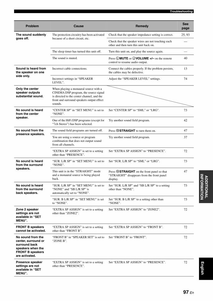
TroubleshootingA
DD
ITIO
NA
L
INF
OR
MA
TIO
NE
ng
lish
Problem Cause RemedySee
page
The sound suddenly goes off.
The protection circuitry has been activated because of a short circuit, etc.
Check that the speaker impedance setting is correct. 25, 93
Check that the speaker wires are not touching each other and then turn this unit back on.
—
The sleep timer has turned this unit off. Turn this unit on, and play the source again. —
The sound is muted. Press LMUTE or JVOLUME +/– on the remote control to resume audio output.
40
Sound is heard from the speaker on one side only.
Incorrect cable connections. Connect the cables properly. If the problem persists, the cables may be defective.
13
Incorrect settings in “SPEAKER LEVEL”.
Adjust the “SPEAKER LEVEL” settings. 74
Only the center speaker outputs substantial sound.
When playing a monaural source with a CINEMA DSP program, the source signal is directed to the center channel, and the front and surround speakers output effect sounds.
No sound is heard from the center speaker.
“CENTER SP” in “SET MENU” is set to “NONE”.
Set “CENTER SP” to “SML” or “LRG”. 73
One of the HiFi DSP programs (except for “7ch Stereo”) has been selected.
Try another sound field program. 42
No sound from the presence speakers.
The sound field programs are turned off. Press ESTRAIGHT to turn them on. 47
You are using a source or program combination that does not output sound from all channels.
Try another sound field program. 37
“EXTRA SP ASSIGN” is set to a setting other than “PRESENCE”.
Set “EXTRA SP ASSIGN” to “PRESENCE”. 72
No sound is heard from the surround speakers.
“SUR. L/R SP” in “SET MENU” is set to “NONE”.
Set “SUR. L/R SP” to “SML” or “LRG”. 73
This unit is in the “STRAIGHT” mode and a monaural source is being played back.
Press ESTRAIGHT on the front panel so that “STRAIGHT” disappears from the front panel display.
47
No sound is heard from the surround back speakers.
“SUR. L/R SP” in “SET MENU” is set to “NONE” and “SB L/R SP” is automatically set to “NONE”.
Set “SUR. L/R SP” and “SB L/R SP” to a setting other than “NONE”.
73
“SUR. B L/R SP” in “SET MENU” is set to “NONE”.
Set “SUR. B L/R SP” to a setting other than “NONE”.
73
Zone 2 speaker settings are not available in “SET MENU”.
“EXTRA SP ASSIGN” is set to a setting other than “ZONE2”.
Set “EXTRA SP ASSIGN” to “ZONE2”. 72
FRONT B speakers cannot be activated.
“EXTRA SP ASSIGN” is set to a setting other than “FRONT B”.
Set “EXTRA SP ASSIGN” to “FRONT B”. 72
No sound from the center, surround or surround back speakers when the FRONT B speakers are activated.
“FRONT B” in “SPEAKER SET” is set to “ZONE B”.
Set “FRONT B” to “FRONT”. 72
Presence speaker settings are not available in “SET MENU”.
“EXTRA SP ASSIGN” is set to a setting other than “PRESENCE”.
Set “EXTRA SP ASSIGN” to “PRESENCE”. 72
97 En
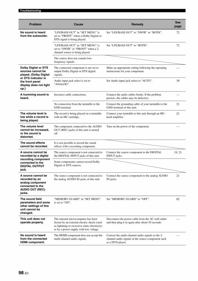
Troubleshooting
Problem Cause RemedySee
page
No sound is heard from the subwoofer.
“LFE/BASS OUT” in “SET MENU” is set to “FRONT” when a Dolby Digital or DTS signal is being played.
Set “LFE/BASS OUT” to “SWFR” or “BOTH”. 72
“LFE/BASS OUT” in “SET MENU” is set to “SWFR” or “FRONT” when a 2-channel source is being played.
Set “LFE/BASS OUT” to “BOTH”. 72
The source does not contain low-frequency signals.
Dolby Digital or DTS sources cannot be played. (Dolby Digital or DTS indicator in the front panel display does not light up.)
The connected component is not set to output Dolby Digital or DTS digital signals.
Make an appropriate setting following the operating instructions for your component.
—
Audio input jack select is set to “ANALOG”.
Set Audio input jack select to “AUTO”. 39
A humming sound is heard.
Incorrect cable connections. Connect the audio cables firmly. If the problem persists, the cables may be defective.
—
No connection from the turntable to the GND terminal.
Connect the grounding cable of your turntable to the GND terminal of this unit.
21
The volume level is low while a record is being played.
The record is being played on a turntable with an MC cartridge.
Connect your turntable to this unit through an MC-head amplifier.
21
The volume level cannot be increased, or the sound is distorted.
The component connected to the AUDIO OUT (REC) jacks of this unit is turned off.
Turn on the power of the component. —
The sound effects cannot be recorded.
It is not possible to record the sound effects with a recording component.
A source cannot be recorded by a digital recording component connected to the DIGITAL OUTPUT jack.
The source component is not connected to the DIGITAL INPUT jacks of this unit.
Connect the source component to the DIGITAL INPUT jacks.
19, 21
Some components cannot record Dolby Digital or DTS sources.
A source cannot be recorded by an analog component connected to the AUDIO OUT (REC) jacks.
The source component is not connected to the analog AUDIO IN jacks of this unit.
Connect the source component to the analog AUDIO IN jacks.
21
The sound field parameters and some other settings of this unit cannot be changed.
“MEMORY GUARD” in “SET MENU” is set to “ON”.
Set “MEMORY GUARD” to “OFF”. 82
This unit does not operate properly.
The internal microcomputer has been frozen by an external electric shock (such as lightning or excessive static electricity) or by a power supply with low voltage.
Disconnect the power cable from the AC wall outlet and then plug it in again after about 30 seconds.
—
No sound is heard from the connected HDMI component.
The HDMI component does not accept the multi-channel audio signals.
Convert the multi-channel audio signals to the 2-channel audio signals at the source component such as a DVD player.
—
98 En
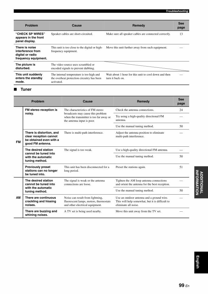
TroubleshootingA
DD
ITIO
NA
L
INF
OR
MA
TIO
NE
ng
lish
Tuner
Problem Cause RemedySee
page
“CHECK SP WIRES” appears in the front panel display.
Speaker cables are short-circuited. Make sure all speaker cables are connected correctly. 13
There is noise interference from digital or radio frequency equipment.
This unit is too close to the digital or high-frequency equipment.
Move this unit further away from such equipment. —
The picture is disturbed.
The video source uses scrambled or encoded signals to prevent dubbing.
This unit suddenly enters the standby mode.
The internal temperature is too high and the overheat protection circuitry has been activated.
Wait about 1 hour for this unit to cool down and then turn it back on.
—
Problem Cause RemedySee
page
FM
FM stereo reception is noisy.
The characteristics of FM stereo broadcasts may cause this problem when the transmitter is too far away or the antenna input is poor.
Check the antenna connections. 24
Try using a high-quality directional FM antenna.
—
Use the manual tuning method. 50
There is distortion, and clear reception cannot be obtained even with a good FM antenna.
There is multi-path interference. Adjust the antenna position to eliminate multi-path interference.
—
The desired station cannot be tuned into with the automatic tuning method.
The signal is too weak. Use a high-quality directional FM antenna. —
Use the manual tuning method. 50
Previously preset stations can no longer be tuned into.
This unit has been disconnected for a long period.
Preset the stations again. 51
AM
The desired station cannot be tuned into with the automatic tuning method.
The signal is weak or the antenna connections are loose.
Tighten the AM loop antenna connections and orient the antenna for the best reception.
—
Use the manual tuning method. 50
There are continuous crackling and hissing noises.
Noise can result from lightning, fluorescent lamps, motors, thermostats and other electrical equipment.
Use an outdoor antenna and a ground wire. This will help somewhat, but it is difficult to eliminate all noise.
—
There are buzzing and whining noises.
A TV set is being used nearby. Move this unit away from the TV set. —
99 En
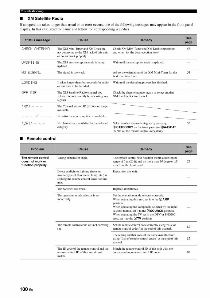
Troubleshooting
XM Satellite RadioIf an operation takes longer than usual or an error occurs, one of the following messages may appear in the front panel display. In this case, read the cause and follow the corresponding remedies.
Remote control
Status message Cause RemedySee
page
CHECK ANTENNA The XM Mini-Tuner and XM Dock are not connected to the XM jack of this unit or do not work properly.
Check XM Mini-Tuner and XM Dock connections and orient for the best reception level.
53
UPDATING The XM user encryption code is being updated.
Wait until the encryption code is updated. —
NO SIGNAL The signal is too weak. Adjust the orientation of the XM Mini-Tuner for the best reception level.
53
LOADING It takes longer than four seconds for audio or text data to be decoded.
Wait until the decoding process has finished. —
OFF AIR The XM Satellite Radio channel you selected is not currently broadcasting any signals.
Check the channel number again or select another XM Satellite Radio channel.
—
<XM> - - - The Channel Station ID (SID) is no longer available.
- - - / - - - No artist name or song title is available.
<CAT> - - - No channels are available for the selected category.
Select another channel category by pressing 4CATEGORY on the front panel (or DA-E/CAT. l / h on the remote control) repeatedly.
55
Problem Cause RemedySee
page
The remote control does not work or function properly.
Wrong distance or angle. The remote control will function within a maximum range of 6 m (20 ft) and no more than 30 degrees off-axis from the front panel.
27
Direct sunlight or lighting (from an inverter type of fluorescent lamp, etc.) is striking the remote control sensor of this unit.
Reposition this unit.
—
The batteries are weak. Replace all batteries. —
The operation mode selector is set incorrectly.
Set the operation mode selector correctly.When operating this unit, set it to the KAMP position.When operating the component selected by the input selector button, set it to the KSOURCE position.When operating the TV set in the DTV or PHONO area, set it to the KTV position.
—
The remote control code was not correctly set.
Set the remote control code correctly using “List of remote control codes” at the end of this manual.
87
Try setting another code of the same manufacturer using “List of remote control codes” at the end of this manual.
87
The ID code of the remote control and the remote control ID of this unit do not match.
Match the remote control ID of this unit with the corresponding remote control ID code. 93
100 En
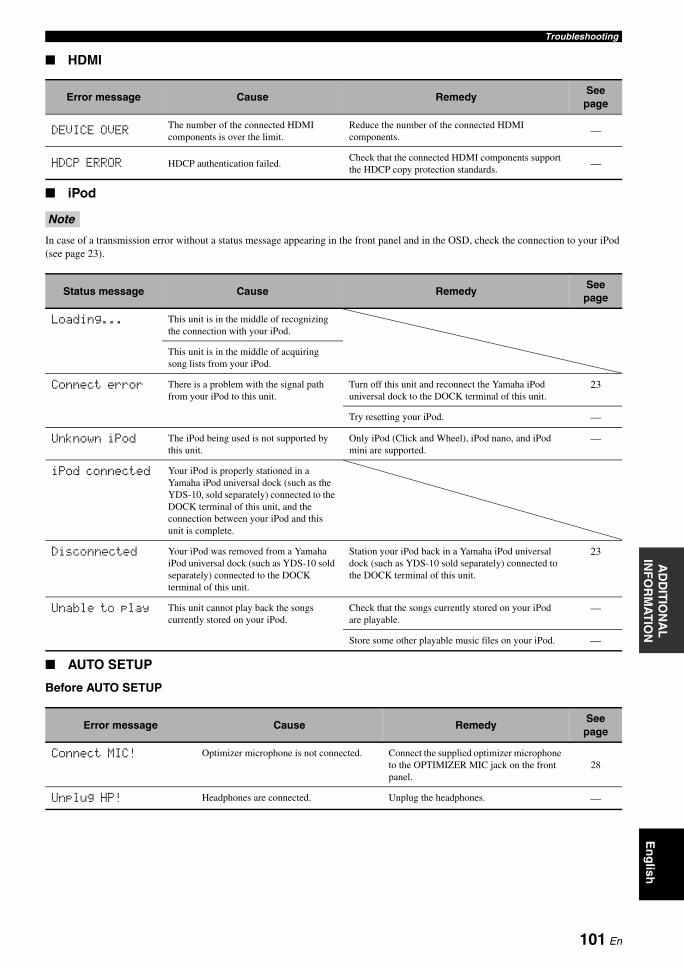
TroubleshootingA
DD
ITIO
NA
L
INF
OR
MA
TIO
NE
ng
lish
HDMI
iPod
In case of a transmission error without a status message appearing in the front panel and in the OSD, check the connection to your iPod (see page 23).
AUTO SETUP
Before AUTO SETUP
Error message Cause RemedySee
page
DEVICE OVERThe number of the connected HDMI components is over the limit.
Reduce the number of the connected HDMI components.
—
HDCP ERROR HDCP authentication failed.Check that the connected HDMI components support the HDCP copy protection standards.
—
Note
Status message Cause RemedySee
page
Loading... This unit is in the middle of recognizing the connection with your iPod.
This unit is in the middle of acquiring song lists from your iPod.
Connect error There is a problem with the signal path from your iPod to this unit.
Turn off this unit and reconnect the Yamaha iPod universal dock to the DOCK terminal of this unit.
23
Try resetting your iPod. —
Unknown iPod The iPod being used is not supported by this unit.
Only iPod (Click and Wheel), iPod nano, and iPod mini are supported.
—
iPod connected Your iPod is properly stationed in a Yamaha iPod universal dock (such as the YDS-10, sold separately) connected to the DOCK terminal of this unit, and the connection between your iPod and this unit is complete.
Disconnected Your iPod was removed from a Yamaha iPod universal dock (such as YDS-10 sold separately) connected to the DOCK terminal of this unit.
Station your iPod back in a Yamaha iPod universal dock (such as YDS-10 sold separately) connected to the DOCK terminal of this unit.
23
Unable to play This unit cannot play back the songs currently stored on your iPod.
Check that the songs currently stored on your iPod are playable.
—
Store some other playable music files on your iPod. —
Error message Cause RemedySee
page
Connect MIC! Optimizer microphone is not connected. Connect the supplied optimizer microphone to the OPTIMIZER MIC jack on the front panel.
28
Unplug HP! Headphones are connected. Unplug the headphones. —
101 En
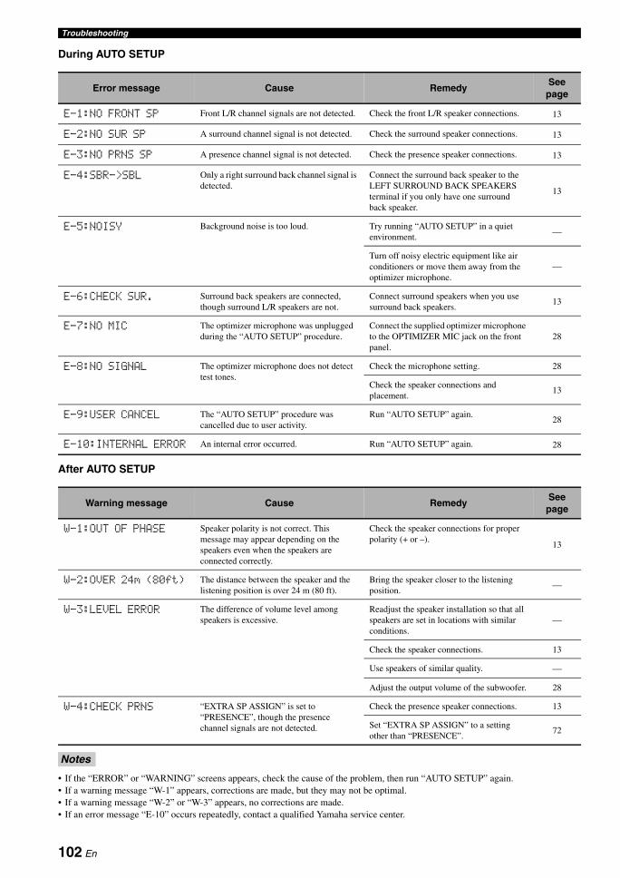
Troubleshooting
During AUTO SETUP
After AUTO SETUP
• If the “ERROR” or “WARNING” screens appears, check the cause of the problem, then run “AUTO SETUP” again.• If a warning message “W-1” appears, corrections are made, but they may not be optimal.• If a warning message “W-2” or “W-3” appears, no corrections are made.• If an error message “E-10” occurs repeatedly, contact a qualified Yamaha service center.
Error message Cause RemedySee
page
E-1:NO FRONT SP Front L/R channel signals are not detected. Check the front L/R speaker connections. 13
E-2:NO SUR SP A surround channel signal is not detected. Check the surround speaker connections. 13
E-3:NO PRNS SP A presence channel signal is not detected. Check the presence speaker connections. 13
E-4:SBR->SBL Only a right surround back channel signal is detected.
Connect the surround back speaker to the LEFT SURROUND BACK SPEAKERS terminal if you only have one surround back speaker.
13
E-5:NOISY Background noise is too loud. Try running “AUTO SETUP” in a quiet environment.
—
Turn off noisy electric equipment like air conditioners or move them away from the optimizer microphone.
—
E-6:CHECK SUR. Surround back speakers are connected, though surround L/R speakers are not.
Connect surround speakers when you use surround back speakers.
13
E-7:NO MIC The optimizer microphone was unplugged during the “AUTO SETUP” procedure.
Connect the supplied optimizer microphone to the OPTIMIZER MIC jack on the front panel.
28
E-8:NO SIGNAL The optimizer microphone does not detect test tones.
Check the microphone setting. 28
Check the speaker connections and placement.
13
E-9:USER CANCEL The “AUTO SETUP” procedure was cancelled due to user activity.
Run “AUTO SETUP” again. 28
E-10:INTERNAL ERROR An internal error occurred. Run “AUTO SETUP” again. 28
Warning message Cause RemedySee
page
W-1:OUT OF PHASE Speaker polarity is not correct. This message may appear depending on the speakers even when the speakers are connected correctly.
Check the speaker connections for proper polarity (+ or –).
13
W-2:OVER 24m (80ft) The distance between the speaker and the listening position is over 24 m (80 ft).
Bring the speaker closer to the listening position.
—
W-3:LEVEL ERROR The difference of volume level among speakers is excessive.
Readjust the speaker installation so that all speakers are set in locations with similar conditions.
—
Check the speaker connections. 13
Use speakers of similar quality. —
Adjust the output volume of the subwoofer. 28
W-4:CHECK PRNS “EXTRA SP ASSIGN” is set to “PRESENCE”, though the presence channel signals are not detected.
Check the presence speaker connections. 13
Set “EXTRA SP ASSIGN” to a setting other than “PRESENCE”.
72
Notes
102 En
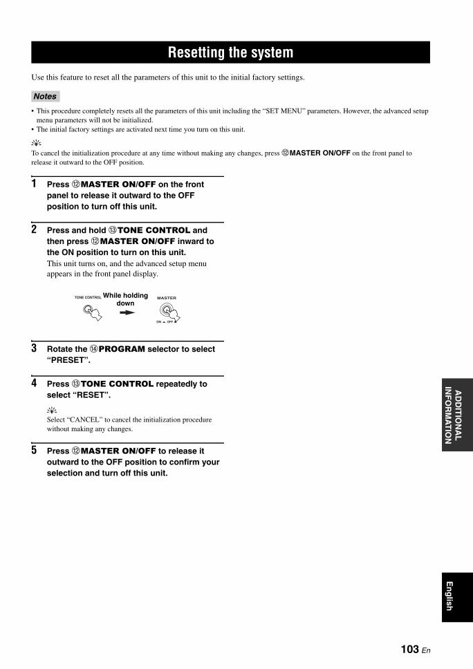
RESETTING THE SYSTEMA
DD
ITIO
NA
L
INF
OR
MA
TIO
NE
ng
lish
Use this feature to reset all the parameters of this unit to the initial factory settings.
• This procedure completely resets all the parameters of this unit including the “SET MENU” parameters. However, the advanced setup menu parameters will not be initialized.
• The initial factory settings are activated next time you turn on this unit.
yTo cancel the initialization procedure at any time without making any changes, press BMASTER ON/OFF on the front panel to release it outward to the OFF position.
1 Press BMASTER ON/OFF on the front panel to release it outward to the OFF position to turn off this unit.
2 Press and hold CTONE CONTROL and then press BMASTER ON/OFF inward to the ON position to turn on this unit.This unit turns on, and the advanced setup menu appears in the front panel display.
3 Rotate the DPROGRAM selector to select “PRESET”.
4 Press CTONE CONTROL repeatedly to select “RESET”.
ySelect “CANCEL” to cancel the initialization procedure without making any changes.
5 Press BMASTER ON/OFF to release it outward to the OFF position to confirm your selection and turn off this unit.
Resetting the system
Notes
TONE CONTROL MASTER
ON OFF
While holding down
103 En
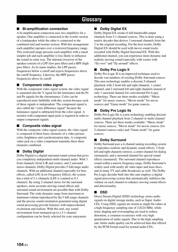
GLOSSARY
Bi-amplification connectionA bi-amplification connection uses two amplifiers for a speaker. One amplifier is connected to the woofer section of a loudspeaker while the other is connected to the combined mid and tweeter section. With this arrangement each amplifier operates over a restricted frequency range. This restricted range presents each amplifier with a much simpler job and each amplifier is less likely to influence the sound in some way. The internal crossover of the speaker consists of a LPF (low pass filter) and a HPF (high pass filter). As its name implies, the LPF passes frequencies below a cutoff and rejects frequencies above the cutoff frequency. Likewise, the HPF passes frequencies above its cutoff.
Component video signalWith the component video signal system, the video signal is separated into the Y signal for the luminance and the PB and PR signals for the chrominance. Color can be reproduced more faithfully with this system because each of these signals is independent. The component signal is also called the “color difference signal” because the luminance signal is subtracted from the color signal. A monitor with component input jacks is required in order to output component signals.
Composite video signalWith the composite video signal system, the video signal is composed of three basic elements of a video picture: color, brightness and synchronization data. A composite video jack on a video component transmits these three elements combined.
Dolby DigitalDolby Digital is a digital surround sound system that gives you completely independent multi-channel audio. With 3 front channels (front L/R and center), and 2 surround stereo channels, Dolby Digital provides 5 full-range audio channels. With an additional channel especially for bass effects, called LFE (Low Frequency Effect), the system has a total of 5.1-channels (LFE is counted as 0.1 channel). By using 2-channel stereo for the surround speakers, more accurate moving sound effects and surround sound environment are possible than with Dolby Surround. The wide dynamic range from maximum to minimum volume reproduced by the 5 full-range channels and the precise sound orientation generated using digital sound processing provide listeners with unprecedented excitement and realism. With this unit, any sound environment from monaural up to a 5.1-channel configuration can be freely selected for your enjoyment.
Dolby Digital EXDolby Digital EX creates 6 full-bandwidth output channels from 5.1-channel sources. This is done using a matrix decoder that derives 3 surround channels from the 2 in the original recording. For the best results, Dolby Digital EX should be used with movie sound tracks recorded with Dolby Digital Surround EX. With this additional channel, you can experience more dynamic and realistic moving sound especially with scenes with “fly-over” and “fly-around” effects.
Dolby Pro Logic IIDolby Pro Logic II is an improved technique used to decode vast numbers of existing Dolby Surround sources. This new technology enables a discrete 5-channel playback with 2 front left and right channels, 1 center channel, and 2 surround left and right channels instead of only 1 surround channel for conventional Pro Logic technology. There are three modes available: “Music mode” for music sources, “Movie mode” for movie sources and “Game mode” for game sources.
Dolby Pro Logic IIxDolby Pro Logic IIx is a new technology enabling discrete multi-channel playback from 2-channel or multi-channel sources. There are three modes available: “Music mode” for music sources, “Movie mode” for movie sources (for 2-channel sources only) and “Game mode” for game sources.
Dolby SurroundDolby Surround uses a 4-channel analog recording system to reproduce realistic and dynamic sound effects: 2 front left and right channels (stereo), a center channel for dialog (monaural), and a surround channel for special sound effects (monaural). The surround channel reproduces sound within a narrow frequency range. Dolby Surround is widely used with nearly all video tapes and laser discs, and in many TV and cable broadcasts as well. The Dolby Pro Logic decoder built into this unit employs a digital signal processing system that automatically stabilizes the volume on each channel to enhance moving sound effects and directionality.
DSDDirect Stream Digital (DSD) technology stores audio signals on digital storage media, such as Super Audio CDs. Using DSD, signals are stored as single bit values at a high-frequency sampling rate of 2.8224 MHz, while noise shaping and oversampling are used to reduce distortion, a common occurrence with very high quantization of audio signals. Due to the high sampling rate, better audio quality can be achieved than that offered by the PCM format used for normal audio CDs.
Glossary
104 En
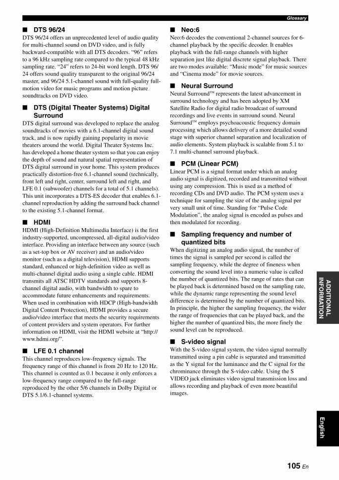
GlossaryA
DD
ITIO
NA
L
INF
OR
MA
TIO
NE
ng
lish
DTS 96/24DTS 96/24 offers an unprecedented level of audio quality for multi-channel sound on DVD video, and is fully backward-compatible with all DTS decoders. “96” refers to a 96 kHz sampling rate compared to the typical 48 kHz sampling rate. “24” refers to 24-bit word length. DTS 96/24 offers sound quality transparent to the original 96/24 master, and 96/24 5.1-channel sound with full-quality full-motion video for music programs and motion picture soundtracks on DVD video.
DTS (Digital Theater Systems) Digital Surround
DTS digital surround was developed to replace the analog soundtracks of movies with a 6.1-channel digital sound track, and is now rapidly gaining popularity in movie theaters around the world. Digital Theater Systems Inc. has developed a home theater system so that you can enjoy the depth of sound and natural spatial representation of DTS digital surround in your home. This system produces practically distortion-free 6.1-channel sound (technically, front left and right, center, surround left and right, and LFE 0.1 (subwoofer) channels for a total of 5.1 channels). This unit incorporates a DTS-ES decoder that enables 6.1-channel reproduction by adding the surround back channel to the existing 5.1-channel format.
HDMIHDMI (High-Definition Multimedia Interface) is the first industry-supported, uncompressed, all-digital audio/video interface. Providing an interface between any source (such as a set-top box or AV receiver) and an audio/video monitor (such as a digital television), HDMI supports standard, enhanced or high-definition video as well as multi-channel digital audio using a single cable. HDMI transmits all ATSC HDTV standards and supports 8-channel digital audio, with bandwidth to spare to accommodate future enhancements and requirements.When used in combination with HDCP (High-bandwidth Digital Content Protection), HDMI provides a secure audio/video interface that meets the security requirements of content providers and system operators. For further information on HDMI, visit the HDMI website at “http://www.hdmi.org/”.
LFE 0.1 channelThis channel reproduces low-frequency signals. The frequency range of this channel is from 20 Hz to 120 Hz. This channel is counted as 0.1 because it only enforces a low-frequency range compared to the full-range reproduced by the other 5/6 channels in Dolby Digital or DTS 5.1/6.1-channel systems.
Neo:6Neo:6 decodes the conventional 2-channel sources for 6- channel playback by the specific decoder. It enables playback with the full-range channels with higher separation just like digital discrete signal playback. There are two modes available: “Music mode” for music sources and “Cinema mode” for movie sources.
Neural SurroundNeural Surround™ represents the latest advancement in surround technology and has been adopted by XM Satellite Radio for digital radio broadcast of surround recordings and live events in surround sound. Neural Surround™ employs psychoacoustic frequency domain processing which allows delivery of a more detailed sound stage with superior channel separation and localization of audio elements. System playback is scalable from 5.1 to 7.1 multi-channel surround playback.
PCM (Linear PCM)Linear PCM is a signal format under which an analog audio signal is digitized, recorded and transmitted without using any compression. This is used as a method of recording CDs and DVD audio. The PCM system uses a technique for sampling the size of the analog signal per very small unit of time. Standing for “Pulse Code Modulation”, the analog signal is encoded as pulses and then modulated for recording.
Sampling frequency and number of quantized bits
When digitizing an analog audio signal, the number of times the signal is sampled per second is called the sampling frequency, while the degree of fineness when converting the sound level into a numeric value is called the number of quantized bits. The range of rates that can be played back is determined based on the sampling rate, while the dynamic range representing the sound level difference is determined by the number of quantized bits. In principle, the higher the sampling frequency, the wider the range of frequencies that can be played back, and the higher the number of quantized bits, the more finely the sound level can be reproduced.
S-video signalWith the S-video signal system, the video signal normally transmitted using a pin cable is separated and transmitted as the Y signal for the luminance and the C signal for the chrominance through the S-video cable. Using the S VIDEO jack eliminates video signal transmission loss and allows recording and playback of even more beautiful images.
105 En
SOUND FIELD PROGRAM INFORMATION
Elements of a sound fieldWhat really creates the rich, full tones of a live instrument are the multiple reflections from the walls of the room. In addition to making the sound live, these reflections enable us to tell where the player is situated as well as the size and shape of the room in which we are sitting.There are two distinct types of sound reflections that combine to make up the sound field in addition to the direct sound coming straight to our ears from the player’s instrument.
Early reflectionsReflected sounds reach our ears extremely rapidly (50 ms to 100 ms after the direct sound), after reflecting from one surface only (for example, from a wall or the ceiling). Early reflections actually add clarity to the direct sound.
ReverberationsThese are caused by reflections from more than one surface (for example, from the walls, and the ceiling) so numerous that they merge together to form a continuous sonic afterglow. They are non-directional and lessen the clarity of the direct sound.
Direct sound, early reflections and subsequent reverberations taken together help us to determine the subjective size and shape of the room, and it is this information that the digital sound field processor reproduces in order to create sound fields.
If you could create the appropriate early reflections and subsequent reverberations in your listening room, you would be able to create your own listening environment. The acoustics in your room could be changed to those of a concert hall, a dance floor, or a room with virtually any size at all. This ability to create sound fields at will is exactly what Yamaha has done with the digital sound field processor.
CINEMA DSPSince the Dolby Surround and DTS systems were originally designed for use in movie theaters, their effect is best felt in a theater having many speakers designed for acoustic effects. Since home conditions, such as room size, wall material, number of speakers, and so on, can differ so widely, it is inevitable that there are differences in the sound heard. Based on a wealth of actually measured data, Yamaha CINEMA DSP uses Yamaha original sound field technology to combine Dolby Pro Logic, Dolby Digital and DTS systems to provide the audiovisual experience of a movie theater in the listening room of your own home.
SILENT CINEMAYamaha has developed a natural, realistic sound effect DSP algorithm for headphones. Parameters for headphones have been set for each sound field so that accurate representations of all the sound field programs can be enjoyed on headphones.
Virtual CINEMA DSPYamaha has developed a Virtual CINEMA DSP algorithm that allows you to enjoy DSP sound field surround effects even without any surround speakers by using virtual surround speakers. It is even possible to enjoy Virtual CINEMA DSP using a minimal two-speaker system that does not include a center speaker.
Sound field program information
106 En
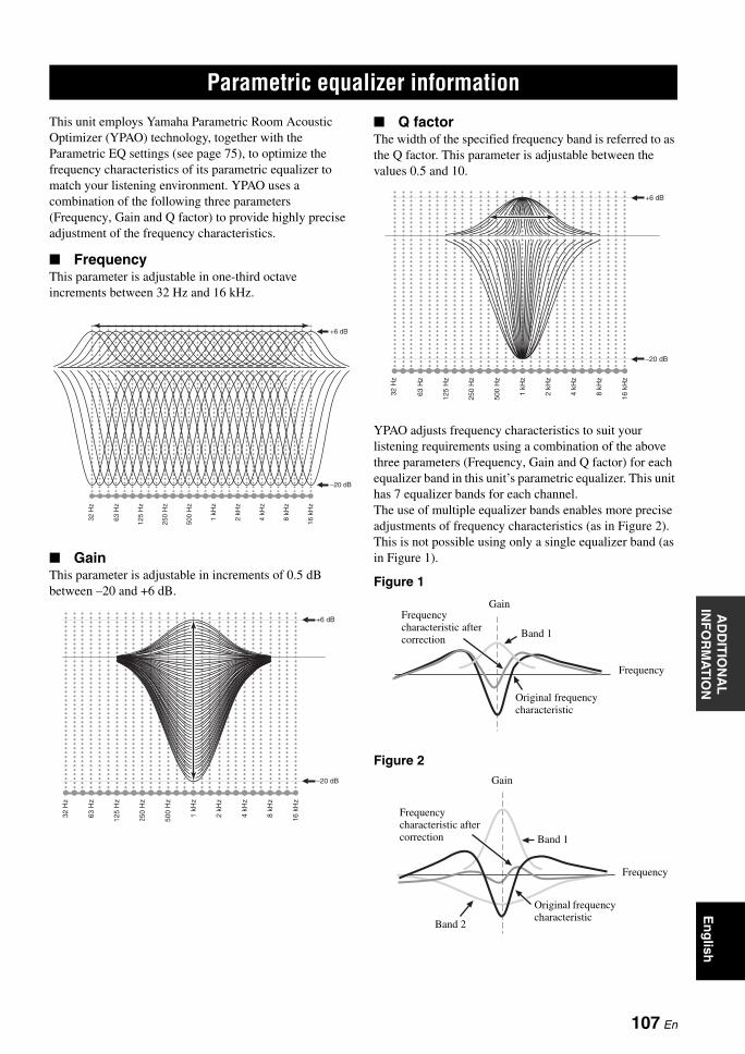
PARAMETRIC EQUALIZER INFORMATIONA
DD
ITIO
NA
L
INF
OR
MA
TIO
NE
ng
lish
This unit employs Yamaha Parametric Room Acoustic Optimizer (YPAO) technology, together with the Parametric EQ settings (see page 75), to optimize the frequency characteristics of its parametric equalizer to match your listening environment. YPAO uses a combination of the following three parameters (Frequency, Gain and Q factor) to provide highly precise adjustment of the frequency characteristics.
FrequencyThis parameter is adjustable in one-third octave increments between 32 Hz and 16 kHz.
GainThis parameter is adjustable in increments of 0.5 dB between –20 and +6 dB.
Q factorThe width of the specified frequency band is referred to as the Q factor. This parameter is adjustable between the values 0.5 and 10.
YPAO adjusts frequency characteristics to suit your listening requirements using a combination of the above three parameters (Frequency, Gain and Q factor) for each equalizer band in this unit’s parametric equalizer. This unit has 7 equalizer bands for each channel.The use of multiple equalizer bands enables more precise adjustments of frequency characteristics (as in Figure 2). This is not possible using only a single equalizer band (as in Figure 1).
Figure 1
Figure 2
Parametric equalizer information
Gain
Frequency
Original frequency characteristic
Band 1
Frequency characteristic after correction
Gain
Frequency
Band 1
Band 2
Frequency characteristic after correction
Original frequency characteristic
107 En
SPECIFICATIONS
AUDIO SECTION• Minimum RMS Output Power for Front, Center, Surround,
Surround back20 Hz to 20 kHz, 0.06% THD, 8 Ω ...................................... 90 W
• Dynamic Power (IHF)Front L/R, 8/6/4/2 Ω ..................................... 120/155/190/235 W
• Maximum Useful Output Power (JEITA) [Asia, General, China and Korea models]
1 kHz, 10% THD, 6 Ω ....................................................... 130 W
• Maximum Output Power [U.K., Europe and Asia models]1 kHz, 0.7% THD, 4 Ω ...................................................... 140 W
• Dynamic Headroom8 Ω ....................................................................................... 1.4 dB
• IEC Output Power [U.K., Europe and Asia models]Front L/R, 1 kHz, 0.06% THD, 8 Ω ................................... 100 W
• Damping Factor (IHF)Front L/R, SPEAKERS A, 20 Hz to 20 kHz, 8 Ω
.................................................................................. 120 or more
• Input Sensitivity/Input ImpedancePHONO (MM) ........................................................ 3.5 mV/47 kΩCD, etc. ................................................................. 200 mV/47 kΩMULTI CH INPUT ............................................... 200 mV/47 kΩ
• Maximum Input VoltagePHONO (MM)
1 kHz, 0.1% THD .............................................. 60 mV or moreCD, etc.
Effect On, 1 kHz, 0.5% THD ............................... 2.3 V or more
• Rated Output Voltage/Output ImpedanceOUT (REC) .......................................................... 200 mV/1.2 kΩPRE OUT ................................................................. 1.0 V/1.2 kΩSUBWOOFER (2ch Stereo, FRONT SP: SMALL)
................................................................................ 1.0 V/1.2 kΩZONE 2 OUT ....................................................... 200 mV/1.2 kΩ
• Headphone Jack Rated Output/ImpedanceCD, etc. (1 kHz, 50 mV, 8 Ω) ................................ 150 mV/100 Ω
• Frequency ResponseCD to Front L/R, 10 Hz to 100 kHz
...................................................................................... +0/–3 dB
• RIAA Equalization DeviationPHONO (MM) ............................................................. 0 ± 0.5 dB
• Total Harmonic DistortionPHONO (MM) to OUT (REC)
20 Hz to 20 kHz, 1 V ............................................ 0.02% or lessCD, etc. to Front L/R
2ch Stereo, 20 Hz to 20 kHz, 50 W, 8 Ω ............... 0.06% or less
• Signal to Noise Ratio (IHF-A Network)PHONO (MM, 5 mV) to Front L/R[Australia, U.K., Europe, Korea and Asia models]
.............................................................................. 81 dB or more[Other models] ....................................................... 86 dB or moreCD, etc. (Effect Off, 250 mV) to Front L/R
............................................................................ 100 dB or more
• Residual Noise (IHF-A Network)Front L/R ................................................................ 150 µV or less
• Channel Separation (1 kHz/10 kHz)PHONO (shortened) to Front L/R ............... 60 dB/55 dB or moreCD, etc.
(5.1 kΩ shortened) to Front L/R .............. 60 dB/45 dB or more
• Volume Control ....................................... MUTE/–80 dB to 16.5 dB
• Tone Control (Front L/R)BASS Boost/Cut ..................................................... ±10 dB/50 HzBASS Turnover Frequency ................................................. 350 HzTREBLE Boost/Cut .............................................. ±10 dB/20 kHzTREBLE Turnover Frequency ........................................... 3.5 kHz
• Filter Characteristics (fc=40/60/80/90/100/110/120/160/200 Hz)H.P.F.
(FRONT SP, CENTER SP, SUR. L/R SP, SUR. B L/R SP: SMALL/SML) ............................................................ 12 dB/oct.
L.P.F. (Subwoofer) ......................................................... 24 dB/oct.
VIDEO SECTION• Video Format (Gray Back)
[U.S.A., Canada, General and Korea models] ..................... NTSC[U.K., Europe, Australia, Asia and China models] ................ PAL
• Video Format (Video Conversion) ................................. NTSC/PAL
• Signal LevelComposite ................................................................. 1 Vp-p/75 ΩS-video ............................ 1 Vp-p/75 Ω (Y), 0.286 Vp-p/75 Ω (C)Component ................... 1 Vp-p/75 Ω (Y), 0.7 Vp-p/75 Ω (PB/PR)
• Maximum Input Level (Video Conversion Off) ............................................................................... 1.5 Vp-p or more
• Signal to Noise Ratio .................................................................................... 50 dB or more
• Frequency Response (MONITOR OUT)Component (Video Conversion Off)
............................................................... 5 Hz to 60 MHz, –3 dB
FM SECTION• Tuning Range
[U.S.A. and Canada models] .......................... 87.5 to 107.9 MHz[Asia and General models] ....... 87.5/87.50 to 108.0/108.00 MHz[Other models] ............................................ 87.50 to 108.00 MHz
• 50 dB Quieting Sensitivity (IHF)Mono ................................................................. 2.8 µV (20.2 dBf)
• Signal to Noise Ratio (IHF)Mono/Stereo ............................................................. 73 dB/70 dB
• Harmonic Distortion (1 kHz)Mono/Stereo ......................................................................... 0.5%
• Antenna Input (unbalanced) ..................................................... 75 Ω
AM SECTION• Tuning Range
[U.S.A. and Canada models] .............................. 530 to 1710 kHz[Asia and General models] ................. 530/531 to 1710/1611 kHz[Other models] .................................................... 531 to 1611 kHz
Specifications
108 En
SpecificationsA
DD
ITIO
NA
L
INF
OR
MA
TIO
NE
ng
lish
GENERAL• Power Supply
[U.S.A. and Canada models] ............................. AC 120 V, 60 Hz[General model]
....................................... AC 110/120/220/230–240 V, 50/60 Hz[Asia model]
..................................................... AC 220/230–240 V, 50/60 Hz[China model] .................................................... AC 220 V, 50 Hz[Korea model] .................................................... AC 220 V, 60 Hz[Australia model] ............................................... AC 240 V, 50 Hz[U.K. and Europe models] ................................. AC 230 V, 50 Hz
• Power Consumption[U.S.A. and Canada models] ................................. 380 W/480 VA[Other models] .................................................................... 390 W
• Standby Power Consumption ....................................... 0.1 W or less
• Maximum Power Consumption [General model only]6ch, 10% THD .................................................................... 800 W
• AC Outlets[U.S.A., Canada, and China models]
.......................................................... 2 (Total 100 W maximum)[Asia, General and Europe models] ...... 2 (Total 50 W maximum)[Australia and U.K. models] ............... 1 (Total 100 W maximum)
• Dimensions (W x H x D) ................................ 435 x 171 x 393 mm(17-1/8 x 6-3/4 x 15-1/2 in)
• Weight .............................................................. 11.6 kg (25 lbs 9 oz)
* Specifications are subject to change without notice.
109 En
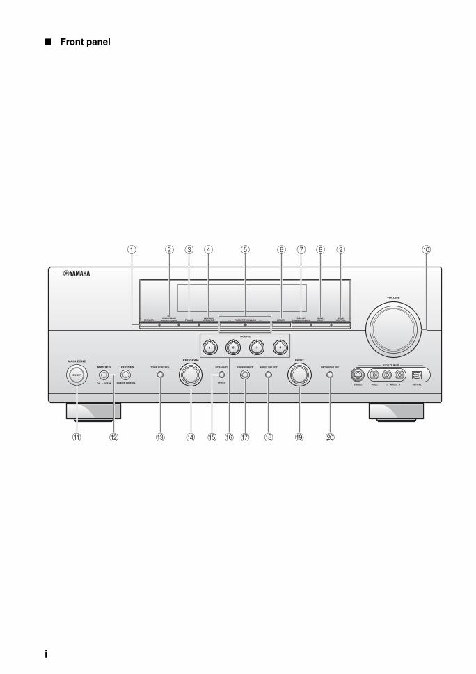
Front panel
VOLUME
INPUTPROGRAM
SCENE
S VIDEO VIDEO OPTICALL AUDIO R
VIDEO AUX
SEARCH MODE
EFFECT
PURE DIRECTSTRAIGHTPHONES
SILENT CINEMA
ON/OFF
AUDIO SELECTTONE CONTROL OPTIMIZER MIC
1 2 3 4
SPEAKERS PRESET/TUNING
EDIT
FM/AM A/B/C/D/ECATEGORY
MEMORY TUNING AUTO/MAN'LDISPLAY
ON/OFFZONE 2
CONTROLZONE
l PRESET/TUNING/CH h
MAIN ZONE
MASTER
ON OFF
G
1 2 3 4 5 6 7 8 9 0
A C D E HB I JF
i
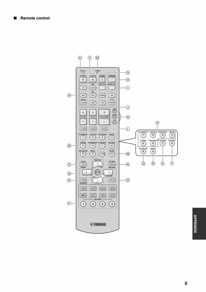
AP
PE
ND
IX
Remote control
REC
SCENE
1 2 3 4
VOLUMETV VOL TV CH
AMP
SOURCE
TV
TRANSMITCODE SET
STANDBY POWERPOWERPOWER
AVTV
MULTI CH IN AUDIO SEL
DOCK
MD
CBL
PHONO
MUTETV MUTE TV INPUT
4321
8
10
7
09
65
SLEEP
MOVIEENTERTAINLIVE/CLUBCLASSICAL
ENT
PURE DIRECTSTRAIGHTSTEREO ENHANCER
NIGHTSUR. DECODE
MENUTITLE
SET MENU
SRCH MODE
XM MEMORY
LEVEL
DISPLAYRETURN
BAND
A-E/CAT.
ENTER
PRESET/CH
CD CD-R
TUNER XM
V-AUX
DVD
DVR VCR
DTV
4321
87
09
65
MOVIEENTERTAINLIVE/CLUBCLASSICAL
PURE DIRECTSTRAIGHTSTEREO ENHANCER
NIGHTSUR. DECODE
G
K
L
M
J
I
H
N
E
F
D
A
U V W
B
C
O
P
Q R S T
ii
INDEX
Numerics1 SOUND MENU, Manual setup ........ 692 INPUT MENU, Manual setup .......... 692ch Enhancer, Sound field program .... 462ch STEREO, Sound field program .... 463 OPTION MENU, Manual setup ....... 707ch Enhancer, Sound field program .... 467ch STEREO, Sound field program .... 4696/24 indicator ..................................... 27
AA)DISPLAY SET, Option menu ......... 81A)I/O ASSIGNMENT, Input menu ..... 78A)SPEAKER SET, Sound menu ......... 72AC OUTLET(S) (SWITCHED) .......... 24Action Game, Sound field program ..... 44Advanced setup .................................... 92Advanced sound configurations ........... 61Adventure, Sound field program ......... 45ALL CH SEARCH, XM tuning ........... 55All Channel Search mode,
XM tuning ....................................... 55All remote control codes resetting ....... 88AM antenna connection ....................... 24AM tuning ............................................ 50Amplifier function OSD display time,
Display settings ............................... 81Audio cable plugs ................................ 15Audio components connection ............. 21AUDIO DELAY, Audio settings ......... 76Audio delay, Audio settings ................. 76Audio information ................................ 41Audio input jacks selection .................. 39AUDIO jacks ....................................... 15Audio jacks .......................................... 15AUDIO SELECT ................................. 39Audio select, Option menu .................. 82Audio settings, Sound menu ................ 76Audio signal flow ................................. 17AUTO SETUP ............................... 28, 69Auto setup ............................................ 69AUTO: RESULT ................................. 31Automatic preset tuning,
FM/AM tuning ................................. 51Automatic tuning, FM/AM tuning ....... 50Available decoders
with Sound field programs .............. 66
BB)INPUT RENAME, Input menu ....... 79B)MEMORY GUARD,
Option menu .................................... 82B)SPEAKER LEVEL, Sound menu .... 74Bass cross over, Speaker settings ........ 74BGV, Multi channel input settings ...... 80BI-AMP, Advanced setup .................... 95Bi-Amplifier, Advanced setup ............. 95
CC)AUDIO SELECT, Option menu ......82C)SP DISTANCE, Sound menu ..........75C)VOLUME TRIM, Input menu .........80C.IMAGE, Decoder parameter ............68Cable plugs ...........................................15CAT SEARCH, XM tuning .................55CD player connection ...........................21Cellar Club, Sound field program ........43CENTER GEQ, Equalizer ....................76Center graphic equalizer, Equalizer .....76CENTER PRE OUT jack
connection ........................................22CENTER SP, Speaker settings .............73Center speaker level,
Sound field parameter ......................66Center speaker, Speaker settings ..........73CENTER WIDTH,
Decoder parameter ...........................68Chamber, Sound field program ............43Charge on standby,
iPod universal dock setting ..............83CLASSICAL, Sound field category .....43CMPNT-V INPUT,
Input/output assignment ...................78COAXIAL IN,
Input/output assignment ...................79COAXIAL INPUT jack assignment,
Input/output assignment ...................79COMPONENT VIDEO jack assignment,
Input/output assignment ...................78COMPONENT VIDEO jacks ..............15Compressed Music Enhancer ...............46Compressed Music Enhancer effect level,
Sound field parameter ......................66Connection, AM antenna connection ...24Connection, audio components ............21Connection, CD player .........................21Connection,
CENTER PRE OUT jack .................22Connection, DVD player ......................19Connection, DVD recorder ..................20Connection, External amplifier ............22Connection, external decoder ...............22Connection, FM antenna ......................24Connection,
FRONT PRE OUT jacks ..................22Connection, iPod universal dock .........23Connection, Multi-format player .........22Connection, Power cable ......................24Connection, projector ...........................18Connection, PVR .................................20Connection, set-top boxes ....................20Connection, speaker cable ....................14Connection,
SUBWOOFER PRE OUT jack ........22Connection,
SUR.BACK PRE OUT jacks ...........22
Connection, SURROUND PRE OUT jacks ........ 22
Connection, Turntable ......................... 21Connection, TV monitor ...................... 18Connection, VCR ................................ 20CROSSOVER, Speaker settings ......... 74CT LEVEL, Sound field parameter ..... 66Current status display .......................... 39
DD)DECODER MODE, Input menu ..... 80D)EQUALIZER, Sound menu ............ 75D)PARAM.INI, Option menu ............. 82Decoder descriptions ........................... 67Decoder indicators ............................... 26Decoder mode ...................................... 80Decoder mode, Input menu ................. 80Decoder select mode, Decoder mode .. 80Decoder selection ................................ 66Decoder type,
Extended surround decoders ........... 77DIALG.LIFT,
Sound field parameter ..................... 62Dialogue left,
Sound field parameter ..................... 62DIGITAL COAXIAL jacks ................. 15DIGITAL OPTICAL jacks .................. 15DIMENSION, Decoder parameter ...... 68DIMMER, Display settings ................. 81Dimmer, Display settings .................... 81Direct number access mode,
XM tuning ....................................... 55DIRECT, Sound field parameter ......... 66DISPLAY SET .................................... 81Display settings, Option menu ............ 81DIST, Auto setup result ....................... 30DISTANCE, Auto setup parameter ..... 30DOCK indicator .................................. 26Drama, Sound field program ............... 45DSP effect level,
Sound field parameter ..................... 62DSP indicators ..................................... 26DSP LEVEL,
Sound field parameter ..................... 62DTS decoder prioritize setting,
Decoder mode ................................. 80DTS Neo:6 Music ................................ 68DVD player connection ....................... 19DVD recorder connection ................... 20Dynamic range, Sound menu .............. 76
EE)LFE LEVEL, Sound menu .............. 76E)MULTI CH SET, Input menu .......... 80E)ZONE2 SET, Option menu ............. 82ENHANCER indicator ........................ 26ENTERTAINMENT,
Sound field category ....................... 44EQ TYPE SELECT, Equalizer ............ 75
Index
110 En
IndexA
DD
ITIO
NA
L
INF
OR
MA
TIO
NE
ng
lish
EQ TYPE, Auto setup parameter ......... 29Equalizer type select, Equalizer ........... 75Equalizer, Sound menu ........................ 75EQUALIZING,
Auto setup parameter ....................... 30Extended surround decoders,
Sound menu ..................................... 77External amplifier connection .............. 22External decoder connection ................ 22EXTRA SP ASSIGN,
Auto setup parameter ....................... 29EXTRA SP ASSIGN,
Speaker settings ............................... 72Extra speaker assignment,
Auto setup parameter ....................... 29Extra speaker assignment,
Speaker settings ............................... 72
FF)DYNAMIC RANGE,
Sound menu ..................................... 76F)XM RADIO SET, Option menu ....... 83FL SCROLL, Display settings ............. 81FM antenna .......................................... 24FM antenna connection ........................ 24FM tuning ............................................ 50FRONT B speaker setting,
Speaker settings ............................... 72FRONT B speakers setting .................. 72FRONT B, Speaker settings ................. 72Front input,
Multi channel input settings ............ 80Front panel display ............................... 26Front panel display scroll,
Display settings ................................ 81FRONT PRE OUT jack connection ..... 22FRONT SP, Speaker settings ............... 73Front speaker set selection ................... 38Front speakers, Speaker settings .......... 73FRONT,
Multi channel input settings ............ 80
GG)AUDIO SET, Sound menu .............. 76G)DOCK SET, Option menu ............... 83
HH)HDMI SET, Sound menu ................ 77Hall in Munich,
Sound field program ........................ 43Hall in Vienna,
Sound field program ........................ 43HDMI ................................................... 16HDMI IN jack assignment,
Input/output assignment .................. 79HDMI IN, Input/output assignment ..... 79HDMI indicator .................................... 26HDMI setting, Sound menu ................. 77HEADPHONE ..................................... 76Headphone, Dynamic range ................. 76HEADPHONE,
Low-frequency effect level .............. 76Headphone,
Low-frequency effect level .............. 76
Headphones ..........................................40Headphones indicator ...........................26HP, Dynamic range ..............................76
II)EXTD SUR., Sound menu .................77Infrared window ...................................27INI VOL., Audio settings .....................77INI VOL., Zone 2 settings ....................83INIT.DLY, Sound field parameter .......63Initial delay, Sound field parameter .....63Initial volume, Audio settings ..............77INPUT CH,
Multi channel input settings .............80Input channel and speaker indicators ...27Input channel indicators .......................27Input channels,
Multi channel input settings .............80Input menu, Manual setup ....................69Input rename, Input menu ....................79Input signal indicators ..........................26Input source indicators .........................26Input source information display .........40Input/output assignment, Input menu ...78iPod universal dock connection ...........23iPod universal dock setting ..................83iPod universal dock setting,
Option menu .....................................83iPod use ................................................58
JJacks .....................................................15
LLEVEL, Auto setup parameter .............30LFE indicator .......................................27LFE/BASS OUT, Speaker settings ......74LFE/Bass out, Speaker settings ............74LIVE/CLUB, Sound field category ......43LIVENESS, Sound field parameter .....64Liveness, Sound field parameter ..........64Low-frequency effect level,
Sound menu .....................................76LVL, Auto setup result .........................30
MManual preset tuning,
FM/AM tuning .................................51MANUAL SETUP ...............................69Manual setup ........................................69Manual tuning, FM/AM tuning ............50MASTER ON/OFF ..............................25MAX VOL., Audio settings .................77MAX VOL., Zone 2 settings ................82Maximum volume ................................77Maximum volume, Audio settings .......77Memory guard, Option menu ...............82MODE,
Extended surround decoders ............77Mode, Extended surround decoders .....77Mono Movie, Sound field program ......45MOVIE, Sound field category .............45MULTI CH INPUT
component selection .........................38
MULTI CH INPUT jacks .................... 22Multi channel input settings,
Input menu ....................................... 80Multi-channel source playback
in 2-channel stereo .......................... 49Multi-channel source playback
with headphones .............................. 46Multi-format player connection ........... 22Multi-information display ................... 27MULTI-ZONE Configuration ............. 89MUSIC ENHANCER,
Sound field category ........................ 46Music Video, Sound field program ..... 44MUTE .................................................. 40MUTE indicator ................................... 26Muting ................................................. 40MUTING TYPE, Audio settings ......... 76Muting type, Audio settings ................ 76
NNeo:6 Cinema, Decoder type ........ 66, 67Neo:6 Music, Decoder type ................. 67Neural Sur., Decoder type ................... 67NIGHT indicator ................................. 26Night listening mode ........................... 49Number of speakers,
Auto setup result .............................. 30
OOperation mode selector ...................... 27OPTICAL IN,
Input/output assignment .................. 79OPTICAL INPUT jack assignment,
Input/output assignment .................. 79OPTICAL OUT,
Input/output assignment .................. 79OPTICAL OUTPUT jack assignment,
Input/output assignment .................. 79OPTIMIZER MIC jack ........................ 28Option menu, Manual setup ................ 70OSD SHIFT, Display settings ............. 81OSD shift, Display settings ................. 81OSD-AMP, Display settings ............... 81OSD-SOURCE, Display settings ........ 81Other components controlling
by remote control ............................ 86Other components controlling,
Remote control ................................ 86
PP.INIT.DLY,
Sound field parameter ..................... 63P.ROOM SIZE,
Sound field parameter ..................... 64PANORAMA, Decoder parameter ...... 68Parameter initialization,
Option menu .................................... 82Parametric equalizer information ...... 107Parametric equalizer type,
Auto setup parameter ...................... 29Parametric equalizer,
Auto setup parameter ...................... 30PHONES jack ...................................... 40PL II Game, Decoder type ................... 67
111 En
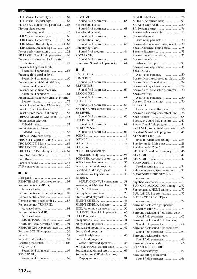
Index
PL II Movie, Decoder type .................. 67PL II Music, Decoder type ................... 67PL LEVEL, Sound field parameter ...... 66Playing video sources
in the background ............................ 40PLII Movie, Decoder type ................... 66PLIIx Game, Decoder type .................. 67PLIIx Movie, Decoder type ........... 66, 67PLIIx Music, Decoder type .................. 67Power cable connection ....................... 24PR LEVEL, Sound field parameter ..... 66Presence and surround back speaker
indicators ......................................... 27Presence left speaker level,
Sound field parameter ...................... 66Presence right speaker level,
Sound field parameter ...................... 66Presence sound field initial delay,
Sound field parameter ...................... 63Presence sound field room size,
Sound field parameter ...................... 64Presence/Surround back channel priority,
Speaker settings ............................... 72Preset channel setting, XM tuning ....... 56Preset SCENE templates ...................... 35Preset Search mode, XM tuning .......... 55PRESET SEARCH, XM tuning .......... 55Preset station selection,
FM/AM tuning ................................. 52Preset stations exchange,
FM/AM tuning ................................. 52PRESET, Advanced setup ................... 93PRIORITY, Speaker settings ............... 72PRO LOGIC II Music .......................... 68PRO LOGIC IIx Music ........................ 68PRO LOGIC, Decoder type ........... 66, 67Projector connection ............................ 18Pure Direct ........................................... 48Pure hi-fi sound .................................... 48PVR connection ................................... 20
RRear panel ............................................ 11REMOTE AMP, Advanced setup ........ 93Remote control AMP ID,
Advanced setup ............................... 93Remote control code default settings ... 87Remote control codes .............................. iRemote control codes setting ............... 87Remote control TUNER ID,
Advanced setup ............................... 94Remote control XM ID,
Advanced setup ............................... 94REMOTE IN/OUT jacks ..................... 23REMOTE TUN, Advanced setup ........ 94REMOTE XM, Advanced setup .......... 94Rename, SCENE template ................... 36Repeat .................................................. 59Repeat, iPod playback .......................... 59Resetting the system .......................... 103REV.DELAY,
Sound field parameter ...................... 65REV.LEVEL,
Sound field parameter ...................... 65
REV.TIME, Sound field parameter ......................65
Reverberation delay, Sound field parameter ......................65
Reverberation level, Sound field parameter ......................65
Reverberation time, Sound field parameter ......................65
Roleplaying Game, Sound field program ........................44
ROOM SIZE, Sound field parameter ......................64
Room size, Sound field parameter .......64
SS VIDEO jacks .....................................15S.INIT.DLY,
Sound field parameter ......................63S.LIVENESS,
Sound field parameter ......................64S.ROOM SIZE,
Sound field parameter ......................64SB INI.DLY,
Sound field parameter ......................63SB L/R SP, Speaker settings ................73SB LEVEL,
Sound field parameter ......................66SB LIVENESS,
Sound field parameter ......................64SB ROOM SIZE,
Sound field parameter ......................64SCENE 1 ................................................9SCENE 2 ................................................9SCENE 3 ................................................9SCENE 4 ................................................9SCENE IR code setting,
Advanced setup ................................95SCENE IR, Advanced setup ................95SCENE template rename .....................36Sci-Fi, Sound field program .................45Selection, Audio input jacks ................39Selection, Front speaker set .................38Selection,
MULTI CH INPUT component .......38Selection, SCENE template .................33SET MENU usage ................................71Set-top box connection .........................20Shuffle, iPod playback .........................59SILENT CINEMA ...............................46SILENT CINEMA indicator ................26SIZE, Auto setup parameter .................30SL LEVEL, Sound field parameter ......66SLEEP indicator ...................................27Sleep timer ...........................................41Sound field indicators ..........................26Sound field programs ...........................42Sound field programs
with headphones ..............................46Sound field programs
without surround speakers ...............46SOUND MENU, Manual setup ...........72Sound menu, Manual setup ..................69Source feature OSD display time,
Display settings ................................81
SP A B indicators ................................ 26SP IMP., Advanced setup .................... 93SP, Auto setup result ........................... 30SP, Dynamic range .............................. 76Speaker cable connection .................... 14Speaker distance,
Auto setup parameter ...................... 30Speaker distance, Auto setup result ..... 30Speaker distance, Sound menu ............ 75Speaker distances ................................ 75Speaker impedance setting .................. 25Speaker impedance,
Advanced setup ............................... 93Speaker level adjustment ..................... 48Speaker level,
Auto setup parameter ...................... 30Speaker level, Auto setup result .......... 30Speaker level, Sound menu ................. 74Speaker settings, Sound menu ............. 72Speaker size, Auto setup parameter .... 30Speaker wiring,
Auto setup parameter ...................... 30Speaker, Dynamic range ...................... 76SPEAKER,
Low-frequency effect level ............. 76Speaker, Low-frequency effect level ... 76Specifications .................................... 108Spectacle, Sound field program ........... 45Sports, Sound field program ................ 44SR LEVEL, Sound field parameter ..... 66Standard, Sound field program ............ 45STANDBY CHARGE,
iPod universal dock setting ............. 83Standby mode, Main zone ................... 25Standby mode, Zone 2 ......................... 91STEREO, Sound field category ........... 46STRAIGHT ......................................... 47STRAIGHT mode ............................... 47SUBWOOFER PHASE,
Speaker settings ............................... 74Subwoofer phase, Speaker settings ..... 74SUBWOOFER PRE OUT jack
connection ....................................... 22Supplied accessories .............................. 3SUPPORT AUDIO, HDMI setting ..... 77Support audio, HDMI setting .............. 77SUR. L/R SP, Speaker settings ........... 73SUR.BACK PRE OUT jack
connection ....................................... 22Surround back left/right speakers,
Speaker settings ............................... 73Surround back sound field initial delay,
Sound field parameter ..................... 63Surround back sound field liveness,
Sound field parameter ..................... 64Surround back sound field room size,
Sound field parameter ..................... 64Surround back speaker level,
Sound field parameter ..................... 66Surround decode mode ........................ 66SURROUND DECODE,
Decoder category ............................ 67Surround left speaker level,
Sound field parameter ..................... 66
112 En
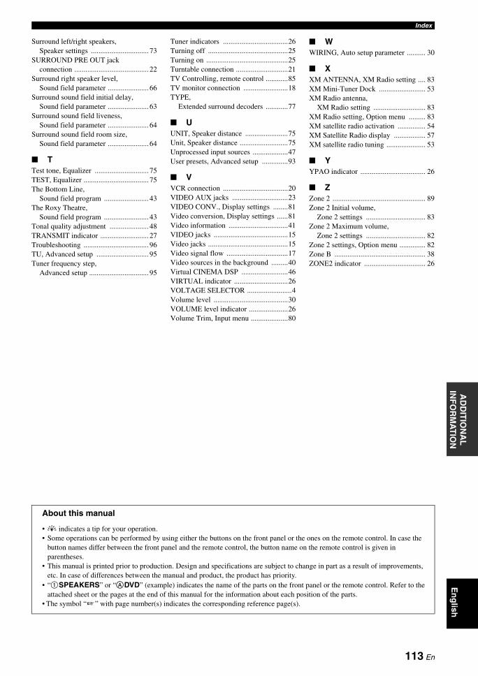
IndexA
DD
ITIO
NA
L
INF
OR
MA
TIO
NE
ng
lish
Surround left/right speakers, Speaker settings ............................... 73
SURROUND PRE OUT jack connection ........................................ 22
Surround right speaker level, Sound field parameter ...................... 66
Surround sound field initial delay, Sound field parameter ...................... 63
Surround sound field liveness, Sound field parameter ...................... 64
Surround sound field room size, Sound field parameter ...................... 64
TTest tone, Equalizer ............................. 75TEST, Equalizer ................................... 75The Bottom Line,
Sound field program ........................ 43The Roxy Theatre,
Sound field program ........................ 43Tonal quality adjustment ..................... 48TRANSMIT indicator .......................... 27Troubleshooting ................................... 96TU, Advanced setup ............................ 95Tuner frequency step,
Advanced setup ................................ 95
Tuner indicators ...................................26Turning off ...........................................25Turning on ............................................25Turntable connection ............................21TV Controlling, remote control ............85TV monitor connection ........................18TYPE,
Extended surround decoders ............77
UUNIT, Speaker distance .......................75Unit, Speaker distance ..........................75Unprocessed input sources ...................47User presets, Advanced setup ..............93
VVCR connection ...................................20VIDEO AUX jacks ..............................23VIDEO CONV., Display settings ........81Video conversion, Display settings ......81Video information ................................41VIDEO jacks ........................................15Video jacks ...........................................15Video signal flow .................................17Video sources in the background .........40Virtual CINEMA DSP .........................46VIRTUAL indicator .............................26VOLTAGE SELECTOR ........................4Volume level ........................................30VOLUME level indicator .....................26Volume Trim, Input menu ....................80
WWIRING, Auto setup parameter .......... 30
XXM ANTENNA, XM Radio setting .... 83XM Mini-Tuner Dock ......................... 53XM Radio antenna,
XM Radio setting ............................ 83XM Radio setting, Option menu ......... 83XM satellite radio activation ............... 54XM Satellite Radio display ................. 57XM satellite radio tuning ..................... 53
YYPAO indicator ................................... 26
ZZone 2 .................................................. 89Zone 2 Initial volume,
Zone 2 settings ................................ 83Zone 2 Maximum volume,
Zone 2 settings ................................ 82Zone 2 settings, Option menu .............. 82Zone B ................................................. 38ZONE2 indicator ................................. 26
About this manual
• y indicates a tip for your operation.• Some operations can be performed by using either the buttons on the front panel or the ones on the remote control. In case the
button names differ between the front panel and the remote control, the button name on the remote control is given in parentheses.
• This manual is printed prior to production. Design and specifications are subject to change in part as a result of improvements, etc. In case of differences between the manual and product, the product has priority.
• “1SPEAKERS” or “ADVD” (example) indicates the name of the parts on the front panel or the remote control. Refer to the attached sheet or the pages at the end of this manual for the information about each position of the parts.
• The symbol “” with page number(s) indicates the corresponding reference page(s).
113 En
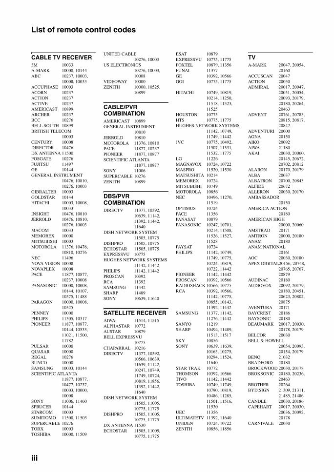
List of remote control codes
CABLE TV RECEIVER3M 10033A-MARK 10008, 10144ABC 10237, 10003,
10008, 10033ACCUPHASE 10003ACORN 10237ACTION 10237ACTIVE 10237AMERICAST 10899ARCHER 10237BCC 10276BELL SOUTH 10899BRITISH TELECOM
10003CENTURY 10008DIRECTOR 10476DX ANTENNA 11500FOSGATE 10276FUJITSU 11497GE 10144GENERAL INSTRUMENT
10476, 10810, 10276, 10003
GIBRALTER 10003GOLDSTAR 10144HITACHI 10003, 10008,
10033INSIGHT 10476, 10810JERROLD 10476, 10810,
10276, 10003MACOM 10033MEMOREX 10000MITSUBISHI 10003MOTOROLA 11376, 10476,
10810, 10276NEC 11496NOVA VISION 10008NOVAPLEX 10008PACE 11877, 10877,
10237, 10008PANASONIC 10000, 10008,
10144, 10107, 10375, 11488
PARAGON 10000, 10008, 10525
PENNEY 10000PHILIPS 11305, 10317PIONEER 11877, 10877,
10144, 10533, 11021, 11500, 11782
PULSAR 10000QUASAR 10000REGAL 10276RUNCO 10000SAMSUNG 10003, 10144SCIENTIFIC ATLANTA
11877, 10877, 10477, 10237, 10003, 10000, 10008
SONY 11006, 11460SPRUCER 10144STARCOM 10003SUMITOMO 11500, 11503SUPERCABLE 10276TORX 10003TOSHIBA 10000, 11509
UNITED CABLE10276, 10003
US ELECTRONICS10276, 10003, 10008
VIDEOWAY 10000ZENITH 10000, 10525,
10899
CABLE/PVR COMBINATIONAMERICAST 10899GENERAL INSTRUMENT
10810JERROLD 10810MOTOROLA 11376, 10810PACE 11877, 10237PIONEER 11877, 10877SCIENTIFIC ATLANTA
11877, 10877SONY 11006SUPERCABLE 10276ZENITH 10899
DBS/PVR COMBINATIONDIRECTV 11377, 10392,
10639, 11142, 11392, 11442, 11640
DISH NETWORK SYSTEM11505, 10775
DISHPRO 11505, 10775ECHOSTAR 11505, 10775EXPRESSVU 10775HUGHES NETWORK SYSTEMS
11142, 11442PHILIPS 11142, 11442PROSCAN 10392RCA 11392SAMSUNG 11442SHARP 11489SONY 10639, 11640
SATELLITE RECEIVERAIWA 11514, 11515ALPHASTAR 10772AUSTAR 10879BELL EXPRESSVU
10775CHAPARRAL 10216DIRECTV 11377, 10392,
10566, 10639, 11639, 11142, 10247, 10749,11749, 10724, 10819, 11856, 11392, 11442, 11640
DISH NETWORK SYSTEM11505, 11005, 10775, 11775
DISHPRO 11505, 11005, 10775, 11775
DX ANTENNA 11530ECHOSTAR 11505, 11005,
10775, 11775
ESAT 10879EXPRESSVU 10775, 11775FOXTEL 10879, 11356FUNAI 11377GE 10392, 10566GOI 10775, 11775
HITACHI 10749, 10819, 10214, 11250, 11518, 11523, 11525
HOUSTON 10775HTS 10775, 11775HUGHES NETWORK SYSTEMS
11142, 10749, 11749, 11442
JVC 10775, 10492, 11507, 11531, 11532, 11775
LG 11226MAGNAVOX 10724, 10722MASPRO 11520, 11530MATSUSHITA 10214MEMOREX 10724MITSUBISHI 10749MOTOROLA 10856NEC 10496, 11270,
11519OPTIMUS 10724PACE 11356PANASAT 10879PANASONIC 10247, 10701,
10214, 11508, 11526, 11527, 11528
PAYSAT 10724PHILIPS 11142, 10749,
11749, 10775, 10724, 10819, 10722, 11442
PIONEER 11142, 11442PROSCAN 10392, 10566RADIOSHACK 10566, 10775RCA 10392, 10566,
11142, 10775, 10855, 10143, 11392, 11442
SAMSUNG 11377, 11142, 11276, 11442
SANYO 11219SHARP 10494, 11489,
11513, 11517SKY 10856SONY 10639, 11639,
10163, 10275, 10294, 11524, 11640
STAR TRAK 10772THOMSON 10392, 10566TIVO 11142, 11442TOSHIBA 10749, 11749,
10790, 10819, 10486, 11285, 11501, 11516,11530
UEC 11356ULTIMATETV 11392, 11640UNIDEN 10724, 10722ZENITH 10856, 11856
TVA-MARK 20047, 20054,
20160ACCUSCAN 20047ACTION 20030ADMIRAL 20017, 20047,
20051, 20054, 20093, 20179, 20180, 20264,20463
ADVENT 20761, 20783, 20815, 20817, 20842
ADVENTURI 20000AGNA 20150AIKO 20092AIWA 21180AKAI 20030, 20060,
20145, 20672, 20702, 20812
ALARON 20170, 20179ALBA 20037ALBATRON 20700, 20843ALFIDE 20672ALLERON 20030, 20170AMBASSADOR
20150AMERICA ACTION
20180AMERICAN HIGH
20000, 20060AMSTRAD 20171AMTRON 20000, 20180ANAM 20180ANAM NATIONAL
20161AOC 20030, 20180APEX DIGITAL20156, 20748,
20765, 20767, 20879
AUDINAC 20180AUDIOVOX 20092, 20179,
20180, 20451, 20623, 20802, 20875
AVENTURA 20171BAYCREST 20186BAYSONIC 20180BEAUMARK 20017, 20030,
20178, 20179BELCOR 20030BELL & HOWELL
20054, 20093, 20154, 20179
BENQ 21032BRADFORD 20180BROCKWOOD 20030, 20178BROKSONIC 20180, 20236,
20463BROTHER 20264BYD:SIGN 21309, 21311,
21485, 21486CANDLE 20030, 20186CAPEHART 20017, 20030,
20036, 20092, 20178
CARNIVALE 20030
iii
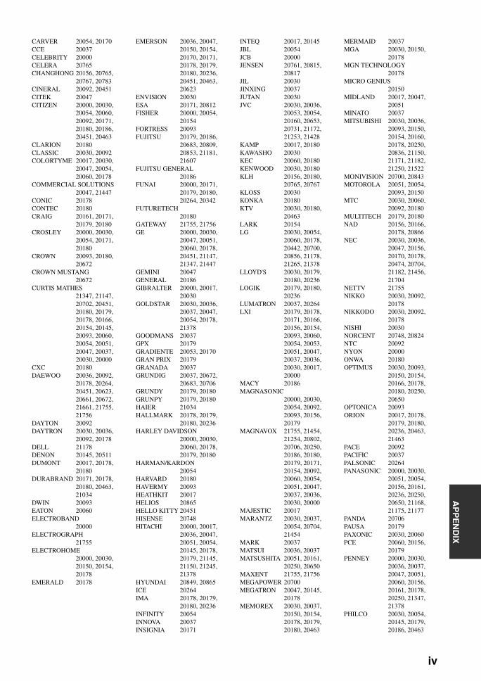
AP
PE
ND
IX
CARVER 20054, 20170CCE 20037CELEBRITY 20000CELERA 20765CHANGHONG 20156, 20765,
20767, 20783CINERAL 20092, 20451CITEK 20047CITIZEN 20000, 20030,
20054, 20060, 20092, 20171, 20180, 20186,20451, 20463
CLARION 20180CLASSIC 20030, 20092COLORTYME 20017, 20030,
20047, 20054, 20060, 20178
COMMERCIAL SOLUTIONS20047, 21447
CONIC 20178CONTEC 20180CRAIG 20161, 20171,
20179, 20180CROSLEY 20000, 20030,
20054, 20171, 20180
CROWN 20093, 20180, 20672
CROWN MUSTANG20672
CURTIS MATHES21347, 21147, 20702, 20451, 20180, 20179, 20178, 20166,20154, 20145, 20093, 20060, 20054, 20051, 20047, 20037,20030, 20000
CXC 20180DAEWOO 20036, 20092,
20178, 20264, 20451, 20623, 20661, 20672,21661, 21755, 21756
DAYTON 20092DAYTRON 20030, 20036,
20092, 20178DELL 21178DENON 20145, 20511DUMONT 20017, 20178,
20180DURABRAND 20171, 20178,
20180, 20463, 21034
DWIN 20093EATON 20060ELECTROBAND
20000ELECTROGRAPH
21755ELECTROHOME
20000, 20030, 20150, 20154, 20178
EMERALD 20178
EMERSON 20036, 20047, 20150, 20154, 20170, 20171, 20178, 20179,20180, 20236, 20451, 20463, 20623
ENVISION 20030ESA 20171, 20812FISHER 20000, 20054,
20154FORTRESS 20093FUJITSU 20179, 20186,
20683, 20809, 20853, 21181, 21607
FUJITSU GENERAL20186
FUNAI 20000, 20171, 20179, 20180, 20264, 20342
FUTURETECH20180
GATEWAY 21755, 21756GE 20000, 20030,
20047, 20051, 20060, 20178, 20451, 21147,21347, 21447
GEMINI 20047GENERAL 20186GIBRALTER 20000, 20017,
20030GOLDSTAR 20030, 20036,
20037, 20047, 20054, 20178, 21378
GOODMANS 20037GPX 20179GRADIENTE 20053, 20170GRAN PRIX 20179GRANADA 20037GRUNDIG 20037, 20672,
20683, 20706GRUNDY 20179, 20180GRUNPY 20179, 20180HAIER 21034HALLMARK 20178, 20179,
20180, 20236HARLEY DAVIDSON
20000, 20030, 20060, 20178, 20179, 20180
HARMAN/KARDON20054
HARVARD 20180HAVERMY 20093HEATHKIT 20017HELIOS 20865HELLO KITTY 20451HISENSE 20748HITACHI 20000, 20017,
20036, 20047, 20051, 20054, 20145, 20178,20179, 21145, 21150, 21245, 21378
HYUNDAI 20849, 20865ICE 20264IMA 20178, 20179,
20180, 20236INFINITY 20054INNOVA 20037INSIGNIA 20171
INTEQ 20017, 20145JBL 20054JCB 20000JENSEN 20761, 20815,
20817JIL 20030JINXING 20037JUTAN 20030JVC 20030, 20036,
20053, 20054, 20160, 20653, 20731, 21172,21253, 21428
KAMP 20017, 20180KAWASHO 20030KEC 20060, 20180KENWOOD 20030, 20180KLH 20156, 20180,
20765, 20767KLOSS 20030KONKA 20180KTV 20030, 20180,
20463LARK 20154LG 20030, 20054,
20060, 20178, 20442, 20700, 20856, 21178,21265, 21378
LLOYD'S 20030, 20179, 20180, 20236
LOGIK 20179, 20180, 20236
LUMATRON 20037, 20264LXI 20179, 20178,
20171, 20166, 20156, 20154, 20093, 20060,20054, 20053, 20051, 20047, 20037, 20036, 20030, 20017,20000
MACY 20186MAGNASONIC
20000, 20030, 20054, 20092, 20093, 20156, 20179
MAGNAVOX 21755, 21454, 21254, 20802, 20706, 20250, 20186, 20180,20179, 20171, 20154, 20092, 20060, 20054, 20051, 20047,20037, 20036, 20030, 20000
MAJESTIC 20017MARANTZ 20030, 20037,
20054, 20704, 21454
MARK 20037MATSUI 20036, 20037MATSUSHITA 20051, 20161,
20250, 20650MAXENT 21755, 21756MEGAPOWER 20700MEGATRON 20047, 20145,
20178MEMOREX 20030, 20037,
20150, 20154, 20178, 20179, 20180, 20463
MERMAID 20037MGA 20030, 20150,
20178MGN TECHNOLOGY
20178MICRO GENIUS
20150MIDLAND 20017, 20047,
20051MINATO 20037MITSUBISHI 20030, 20036,
20093, 20150, 20154, 20160, 20178, 20250,20836, 21150, 21171, 21182, 21250, 21522
MONIVISION 20700, 20843MOTOROLA 20051, 20054,
20093, 20150MTC 20030, 20060,
20092, 20180MULTITECH 20179, 20180NAD 20156, 20166,
20178, 20866NEC 20030, 20036,
20047, 20156, 20170, 20178, 20474, 20704,21182, 21456, 21704
NETTV 21755NIKKO 20030, 20092,
20178NIKKODO 20030, 20092,
20178NISHI 20030NORCENT 20748, 20824NTC 20092NYON 20000ONWA 20180OPTIMUS 20030, 20093,
20150, 20154, 20166, 20178, 20180, 20250,20650
OPTONICA 20093ORION 20017, 20178,
20179, 20180, 20236, 20463, 21463
PACE 20092PACIFIC 20037PALSONIC 20264PANASONIC 20000, 20030,
20051, 20054, 20156, 20161, 20236, 20250,20650, 21168, 21175, 21177
PANDA 20706PAUSA 20179PAXONIC 20030, 20060PCE 20060, 20156,
20179PENNEY 20000, 20030,
20036, 20037, 20047, 20051, 20060, 20156,20161, 20178, 20250, 21347, 21378
PHILCO 20030, 20054, 20145, 20179, 20186, 20463
iv
PHILIPS 20030, 20037, 20054, 20171, 20186, 20690, 21254, 21454,21455
PILOT 20030, 20051, 20060, 20178
PIONEER 20166, 20679, 20866, 21260
POLAROID 20765, 20865PORTLAND 20092, 20451PRECISION 20180, 20236PRIMA 20761, 20783,
20815, 20817PRINCETON 20700PRISM 20051, 20250PROSCAN 20047, 21347,
21447PROTEC 20037, 20264PROTON 20178PROVISION 20037PULSAR 20017, 20092PULSER 20092, 20178QUARTZ 20150, 20178QUASAR 20051, 20250,
20650R-LINE 20037RABBIT 20047RADIOSHACK 20030, 20047,
20150, 20154, 20178, 20180
RCA 20000, 20047, 20051, 20054, 20090, 20093, 20178, 20679,21047, 21147, 21247, 21347, 21447, 21547
REALISTIC 20030, 20047, 20150, 20154, 20178, 20180
REVOX 20037RUNCO 20017, 20030,
20060SAMPO 20030, 20047,
21755, 21756SAMSUNG 20017, 20030,
20036, 20037, 20047, 20054, 20060, 20154,20178, 20264, 20587, 20702, 20766, 20812, 20814, 21060
SANKY 20030, 20060SANSUI 20030, 20060,
20463SANYO 20000, 20036,
20037, 20047, 20054, 20088, 20154, 20171,20376, 20424, 20463, 21179, 21755
SAVILLE 20060SCOTCH 20178SCOTT 20030, 20178,
20179, 20180, 20236
SEARS 20179, 20178, 20171, 20166, 20156, 20154, 20093, 20060,20054, 20053, 20051, 20047, 20037, 20036, 20030, 20017,20000
SHARP 20036, 20054, 20093, 20179, 20180, 20256, 20787, 21165
SHENG CHIA 20093SHIVAKI 20037, 20178SIEMENS 20145SIGNATURE 20030, 20047,
20093, 20179SIMPSON 20030, 20178,
20186SINGER 20060, 20092SKY-NORTH 20037SOLAR DRAPE
20000SONY 20000, 20017,
20036, 20053, 20150, 20154, 21100, 21167,21300, 21651
SOUNDESIGN20178, 20179, 20180, 20186
SPECTRAVISION20156, 20178, 20179, 20186
SQUAREVIEW20171
SR2000 20154, 20171SSS 20180STARLITE 20180, 20236STUDIO EXPERIENCE
20843SUPERSCAN 20093, 20864SUPRE-MACY 20186SUPREME 20000SV2000 20054SVA 20587, 20748,
20865, 20870, 20871
SYLVANIA 20000, 20030, 20036, 20037, 20047, 20051, 20054, 20092,20154, 20171, 20178, 20179, 20186
SYMPHONIC 20000, 20171, 20178, 20179, 20180
TANDY 20093TATUNG 20000, 20037,
20051, 21756TEAC 20037, 20154,
20264, 20706TECHNICS 20051, 20054,
20250TECHNOL ACE
20179TECHNOVOX 20030TECHWOOD 20051, 20060,
20250
TEKNIKA 20054, 20060, 20092, 20150, 20178, 20179, 20180, 20186,20463
TELECOLOR 20017TELEFUNKEN
20702TELETON 20186TEVION 20037THOMAS 20047, 20178THOMSON 20047, 21447TMK 20178, 20180,
20236TNCI 20017TOCOM 20156TOSHIBA 21704, 21656,
21456, 21356, 21265, 21256, 21173, 21169,21156, 21145, 20845, 20650, 20509, 20264, 20166, 20156,20154, 20150, 20145, 20060, 20036
TOTEVISION 20051TOYOMENKA 20178TRUETONE 20051, 20250TVS 20463ULTRA 20092UNIVERSAL 20047UNIVERSUM 20036, 20037,
20170, 20264, 20474
V 20864, 20885, 21755, 21756
VECTOR RESEARCH20030
VICTOR 20036, 20053, 20160, 20653
VIDIKRON 20054VIDTECH 20036, 20178VIEWSONIC 20857, 20864,
20885, 21755VIKING 20060VISIO 20864, 20885,
21755, 21756VIZIO 20864, 20885,
21756WARDS 20000, 20017,
20030, 20037, 20047, 20051, 20054, 20093,20154, 20166, 20178, 20179, 20186, 20236, 20866, 21156
WAYCON 20156WELTON 20178WESTINGHOUSE
20000, 20451, 20885, 20889
WHITE WESTINGHOUSE20179, 20236, 20451, 20463, 20623, 20889
WORLD 20180, 20236, 20451, 20463
XR-1000 20154, 20171, 20179, 20180
YAMAHA 20030, 20650, 20769, 21405, 21406, 21407, 21522
YORX 20030ZENITH 20000, 20017,
20030, 20037, 20047, 20092, 20093, 20145,20160, 20171, 20178, 20463, 20812, 21145, 21265
PVRABS 31972ALIENWARE 31972CYBERPOWER
31972DELL 31972DIRECTV 30739GATEWAY 31972HEWLETT PACKARD
31972HITACHI 31718HOWARD COMPUTERS
31972HP 31972HUGHES NETWORK SYSTEMS
30739HUMAX 30739HUSH 31972IBUYPOWER 31972JVC 31279LINKSYS 31972MEDIA CENTER PC
31972MICROSOFT 31972MIND 31972MITSUBISHI 31714NIVEUS MEDIA
31972NORTHGATE 31972PANASONIC 30616, 31244,
31732, 31807, 31808, 31809
PHILIPS 30618, 30739PIONEER 31803RCA 30880REPLAYTV 30614, 30616SAMSUNG 30739SHARP 31742, 31810SONIC BLUE 30614, 30616SONY 30636, 31447,
31448, 31636, 31972
STACK 9 31972SYSTEMAX 31972TAGAR SYSTEMS
31972TIVO 30618, 30636,
30739TOSHIBA 30828, 31008,
31739, 31972, 31996
TOUCH 31972VICTOR 31706VIEWSONIC 31972VOODOO 31972ZT GROUP 31972
v
AP
PE
ND
IX
VCR A-MARK 30037, 30240,
30000ABS 31972ADMIRAL 30060, 30048,
30039, 30047, 30104, 30209
ADVENTURA 30037, 30240, 30000
AIWA 30037, 30000, 30307, 30348, 31284, 31291, 31332, 31336
AKAI 30041ALBA 30209ALIENWARE 31972ALLEGRO 30039AMERICAN HIGH
30035, 30081AMSTRAD 30000ANAM NATIONAL
30226ASHA 30240ASTRA 30035, 30240AUDIOVOX 30037, 30038AVIS 30000BEAUMARK 30240BELL & HOWELL
30035, 30048, 30039, 30000, 30104
BROKSONIC 30184, 30121, 30209, 30348, 31479
CALIX 30037CANDLE 30037, 30038CANON 30035, 30034CARRERA 30240CARVER 30035, 30081CITIZEN 30035, 30037,
30240, 30000, 30209, 31278
CLASSIC 30037COLORTYME 30060, 30035,
30045COLT 30000CRAIG 30037, 30047,
30240CRITERION 30000CROSLEY 30035, 30081,
30000CURTIS MATHES
30060, 30035, 30162, 30240, 30000, 30041, 31035
CYBERNEX 30240CYBERPOWER
31972DAEWOO 30037, 30045,
31278DAYTRON 30037DELL 31972DENON 30081, 30042DERWENT 30041DIRECTV 30739DUAL 30000DURABRAND 30039, 30038DYNATECH 30240, 30000ELECTROHOME
30060, 30037, 30240, 30000, 30043, 30209
ELECTROPHONIC30037
EMERALD 30184, 30121EMEREX 30032EMERSON 30037, 30184,
30240, 30000, 30121, 30043, 30209, 30348,31278, 31479
FISHER 30039, 30047, 30000, 30104
FUJI 30035, 30033FUJITSU 30045, 30000FUNAI 30037, 30000,
31333GARRARD 30000GATEWAY 31972GE 30060, 30035,
30048, 30240, 30000, 30807, 31035, 31060
GEMINI 30060GENERAL 30045GENEXXA 30037, 30000GO VIDEO 30240, 30614GOLDSTAR 30035, 30037,
30039, 30000, 30038, 31237
GOODMANS 30037, 30081, 30000
GRADIENTE 30000GRANADA 30081, 30042GRUNDIG 30081, 30034,
30226HARLEY DAVIDSON
30000HARMAN/KARDON
30081, 30038HEWLETT PACKARD
31972HI-Q 30035, 30047,
30000HITACHI 30035, 30037,
30045, 30000, 30042, 30041, 30166, 31286,31326, 31718
HOWARD COMPUTERS31972
HP 31972HUGHES NETWORK SYSTEMS
30042, 30739HUMAX 30739HUSH 31972HYTEK 30047, 30000IBUYPOWER 31972ITT NOKIA 30240, 30041JANEIL 30240JENSEN 30067, 30041JVC 30067, 30041,
31279, 31299, 31329
KEC 30037KENWOOD 30067, 30041,
30038KODAK 30035, 30037KTV 30000LG 30037, 30240,
30038LIFETEC 30348LINKSYS 31972LLOYD'S 30240, 30000,
30038LOEWE 30081LOGIK 30240, 30000
LXI 30037, 30000, 30042, 30067
M ELECTRONIC30240
MAGNASONIC30037, 30240, 30000, 31278
MAGNAVOX 30035, 30037, 30048, 30039, 30081, 30240, 30000, 30226,30618, 31781
MAGNIN 30240MARANTZ 30035, 30081,
30038, 31381MARTA 30037MATSUI 30037, 30209,
30348MATSUSHITA 30035, 30162,
30081, 30226MEDIA CENTER PC
31972MEDION 30348MEI 30035MEMOREX 30035, 30162,
30037, 30048, 30039, 30047, 30240, 30000,30104, 30209, 30307, 30348, 31237
METZ 30037MGA 30060, 30240,
30043MGN TECHNOLOGY
30240MICROSOFT 31972MIDLAND 30240MIND 31972MINOLTA 30042MITSUBISHI 30060, 30048,
30047, 30000, 30042, 30067, 30043, 30041,30807, 31343, 31714
MOTOROLA 30035, 30048MTC 30240, 30000MTX 30000MULTITECH 30039, 30000NAD 30240, 30104NEC 30104, 30067,
30041, 30038NIKKO 30037NIKKODO 30037NIKON 30034NISHI 30240NIVEUS MEDIA
31972NOBLEX 30240NORTHGATE 31972OLYMPUS 30035, 30162,
30104, 30226OPTIMUS 31062, 30035,
30162, 30037, 30048, 30047, 30240, 30000,30104
ORION 30184, 30240, 30000, 30104, 30121, 30209, 31479
PANAMA 30035
PANASONIC 31062, 30035, 30162, 30000, 30225, 30226, 30614, 30616,31035, 31244, 31292, 31308, 31732, 31807, 31808, 31809
PENNEY 30035, 30162, 30037, 30047, 30081, 30240, 30000, 30042,30067, 30038, 31035, 31237
PENTAX 30042PHILCO 30035, 30081,
30000, 30209PHILIPS 30035, 30162,
30048, 30081, 30045, 30000, 30209, 30034,30616, 30618, 30739, 31381
PILOT 30037PIONEER 30162, 30081,
30042, 30067, 31803
POLK AUDIO 30081PROFITRONIC
30240PROSCAN 30060, 31060PROTEC 30000PULSAR 30039, 30240PULSER 30240QUARTZ 30035, 30047QUASAR 30035, 30162,
30226, 31035RADIOSHACK
30035, 30162, 30037, 30048, 30047, 30240, 30000, 30104
RADIX 30037RANDEX 30037RCA 30060, 30035,
30048, 30240, 30045, 30000, 30042, 30166,30807, 30880, 31035, 31060
REALISTIC 30035, 30162, 30037, 30048, 30047, 30240, 30000, 30104,30121
REPLAYTV 30614, 30616RICAVISION 31972RICOH 30034RUNCO 30039SAMSUNG 30060, 30240,
30045, 30000, 30038, 30739, 31014
SAMTRON 30240SANKY 30048, 30039SANSUI 30240, 30000,
30067, 30209, 30041, 31479
SANYO 30047, 30240, 30000, 30104, 31330, 31331
SCOTT 30184, 30045, 30121, 30043
vi
SEARS 30060, 30035, 30162, 30037, 30048, 30039, 30047, 30033,30045, 30000, 30042, 30104, 30067, 30043, 30209, 30041,30034, 31237
SHARP 30048, 30047, 30032, 30000, 30807, 31285, 31742, 31810
SHINTOM 30039, 30240, 30000
SHOGUN 30240SIEMENS 30037, 30104SIGNATURE 30060, 30035,
30037, 30048, 30000
SINGER 30037, 30240SONIC BLUE 30614, 30616SONY 30035, 30047,
30032, 30033, 30000, 30067, 30034, 30226,30636, 31232, 31295, 31296, 31447, 31448, 31636, 31972
SOUNDMASTER30000
STACK 9 31972STS 30042SV2000 30000SVA 30000SYLVANIA 30035, 30081,
30000, 30043, 31781
SYMPHONIC 30240, 30000SYSTEMAX 31972TAGAR SYSTEMS
31972TANDY 30000, 30104TATUNG 30048, 30081,
30000, 30067, 30041
TEAC 30000, 30067, 30041
TECHNICS 30035, 30162, 30037, 30000
TEKNIKA 30035, 30037, 30000
TELECORDER 30240TELEFUNKEN 30041THOMAS 30000THOMSON 30060, 30041TIVO 30618, 30636,
30739, 31996TMK 30240, 30000TNIX 30037TOCOM 30240TOSHIBA 30240, 30045,
30000, 30042, 30043, 30209, 30041, 30828,30845, 31008, 31145, 31323, 31739, 31972, 31996
TOTEVISION 30037, 30240TOUCH 31972TRIX 30037ULTRA 30045UNITECH 30240
VECTOR 30045VECTOR RESEARCH
30184, 30038VICTOR 30067, 30041,
31299, 31706VIDEO CONCEPTS
30045VIDEOMAGIC 30037VIDEOSONIC 30240, 30000VIEWSONIC 31972VILLAIN 30000VOODOO 31972WARDS 30060, 30035,
30037, 30048, 30047, 30081, 30033, 30240,30045, 30000, 30042, 30043, 30041, 30038
WHITE WESTINGHOUSE30000, 30209
WORLD 30209XR-1000 30035, 30240,
30000YAMAHA 30041, 30038ZENITH 30037, 30039,
30033, 30000, 30209, 30041, 30034, 31479
ZT GROUP 31972
DVD PLAYER3D LAB 40503, 40539ACCURIAN 41416ADVENT 41016AIWA 40641AKAI 40695, 40705,
40770, 40899ALBA 40672, 40717ALCO 40790ALLEGRO 40869AMPHION MEDIA WORKS
40872AMW 40872APEX DIGITAL
40533, 40672, 40717, 40755, 40794, 40796, 40797, 40830,41004, 41020, 41056, 41061, 41100
ARRGO 41023ASPIRE DIGITAL
41168AUDIOVOX 40717, 40790BEL CANTO DESIGN
41571BLAUPUNKT 40717BLUE PARADE40571BLUE SKY 40695BRANDT 40651BROKSONIC 40695BYD:SIGN 40872CALIFORNIA AUDIO LABS
40490CELESTIAL 41020CENTREX 40672, 41004CINEA 40831CINEVISION 40876, 40869CITIZEN 41003, 41277CLAIRTONE 40571COBY 40778, 41086,
41107
CRAIG 40831CREATIVE 40503, 40539CURTIS MATHES
41087CYBERHOME 40816, 40874,
41023, 41024, 41117, 41129
CYTRON 40705DAEWOO 40784, 40705,
40770, 40869, 41169, 41172
DANSAI 40770DAYTEK 40872DECCA 40770DENON 40490, 40634,
41282, 41634DENVER 40778DIGITREX 40672DISNEY 40675, 41270DIVIDO 40705DUAL 40675DURABRAND 41127DVD2000 40521ELECTROHOME
41003EMERSON 40591, 40675,
40821, 41268ENTERPRISE 40591ENTIVO 40503, 40539ENZER 40770ESA 40821, 41268FIRSTLINE 40651FISHER 40670FUNAI 40675, 41268GATEWAY 41158GE 40522, 40815,
40717GO VIDEO 40573, 40744,
40717, 40741, 40783, 40869, 41044, 41075,41099, 41158, 41304, 41730
GOLDSTAR 40741, 40801, 40869
GOODMANS 40790GRADIENTE 40490, 40651GREENHILL 40717GRUNDIG 40539, 40705HARMAN/KARDON
40582, 40702HITACHI 40573, 40664,
41247, 41664, 41764
HITEKER 40672I-O DATA 41405ILO 41348INITIAL 40717INSIGNIA 41268INTEGRA 40571, 40627,
41634IRT 40783JBL 40702JENSEN 41016JMB 40695JVC 40558, 40623,
40867, 41164, 41241, 41275, 41590, 41592,41594
KAWASAKI 40790KENWOOD 40490, 40534KLH 40717, 40790,
41020, 41149KLOSS 40533
KOSS 40651, 41061LASONIC 40627, 40798LECSON 41533LENOXX 41127LG 40591, 40741,
40801, 40869, 41600
LITEON 41058, 41158, 41416, 41440
LOEWE 40741LOGIX 40783MAGNASONIC
40651, 40675MAGNAVOX 40503, 40539,
40646, 40675, 40821, 41268
MARANTZ 40503, 40539, 40675, 41627
MCINTOSH 41533MEDION 40651MEMOREX 40695, 40831,
41270MICROSOFT 40522, 41708MINATO 40752MINTEK 40839, 40717MITSUBISHI 41521, 40521,
41403, 41629NAD 40591, 40741NAIKO 40770NEC 40785, 40869,
41404NESA 40717NEXXTECH 41402NORCENT 41003, 40872,
41107ONKYO 40503, 40627,
40792, 41612, 41627
OPTIMUS 40571ORION 41695ORITRON 40651PALSONIC 40672PANASONIC 40503, 40490,
40571, 40703, 41010, 41011, 41282, 41362,41462, 41490, 41632, 41641, 41762
PHILIPS 40503, 40539, 40646, 40675, 40854, 41260, 41267, 41354
PIANODISC 41024PIONEER 40525, 40571,
40631, 40638, 41475, 41476, 41571
POLAROID 41020, 41061, 41086
POLK AUDIO 40539PORTLAND 40770PRESIDIAN 40675PRIMA 41016PROCEED 40672PROSCAN 40522PROVISION 40778QWESTAR 40651RADIONETTE 40741RADIOSHACK
40571RCA 40522, 40571,
40717, 40790, 40822, 41022, 41132
vii
AP
PE
ND
IX
REALISTIC 40571REOC 40752RIO 40869ROTEL 40623ROWA 41004SABA 40651SAMPO 40752SAMSUNG 40490, 40573,
40744, 40820, 40899, 41044, 41075, 41599
SANSUI 40695, 41695SANYO 40670, 40675,
40695, 41583SCHNEIDER 40783SCHWAIGER 40752SENSORY SCIENCE
41158SHARP 40630, 40675,
40752, 41256, 41556, 41642, 42002
SHARPER IMAGE41117
SHERWOOD 40770SHINSONIC 40533, 40839SLIM ART 40784SONIC BLUE 40573, 40783,
40869, 41099SONY 40533, 41533,
40864, 40772, 41033, 41069, 41070, 41431,41633
SUPERSCAN 40821SVA 40717SYLVANIA 40675, 40821,
41268SYMPHONIC 40675, 40821,
41268TATUNG 40770TEAC 40571, 40717,
40790TECHNICS 40490, 40703TECHNIKA 40770TEVION 40651THETA DIGITAL
40571THOMSON 40522TOSHIBA 40503, 40573,
40539, 40695, 41045, 41154, 41510, 41595,41639
UNIMAX 40770UNIVERSUM 40591URBAN CONCEPTS
40503, 40539US LOGIC 40839VENTURER 40790VICTOR 41241, 41597WYSE 41652XBOX 40522, 41708YAMAHA 40490, 40539,
40545, 41282, 42000, 42001
YAMAKAWA 40872ZENITH 40503, 40591,
40741, 40869ZEUS 40784
LD PLAYERAIWA 40203CARVER 40064DENON 40059, 40172,
40241DISCO VISION
40023FUNAI 40203HITACHI 40023KENWOOD 40236, 40258MAGNAVOX 40064, 40217,
40241MARANTZ 40064MITSUBISHI 40059, 40241NAD 40059OPTIMUS 40059PANASONIC 40204PHILIPS 40064PIONEER 40059, 40023,
40241QUASAR 40204REALISTIC 40203SEGA 40023SHARP 40001SONY 40193, 40201TECHNICS 40204TOSHIBA 40059VICTOR 40245WARDS 40059YAMAHA 40217
DVD RECORDERACCURIAN 51416APEX DIGITAL
51056ASPIRE DIGITAL
51168COBY 51086CYBERHOME 51129DENON 50490EMERSON 50675FUNAI 50675GATEWAY 51158GO VIDEO 50741, 51158,
51304, 51730HITACHI 51664, 51764JVC 51164, 51275LG 50741LITEON 51158, 51416,
51440MAGNAVOX 50646, 50675MITSUBISHI 51629PANASONIC 50490, 51010,
51011PHILIPS 50646PIONEER 50631, 51475,
51476POLAROID 51086RCA 50522SAMSUNG 50490SENSORY SCIENCE
51158SHARP 50630, 50675,
51556, 51642, 52002
SONY 51033, 51069, 51070, 51431
SYLVANIA 50675TOSHIBA 51510, 51639VICTOR 51275YAMAHA 52001ZENITH 50741
CD PLAYER ADC 60018ADCOM 60234AIWA 60157AKAI 60083, 60643,
61688ALBA 60625ANAM NATIONAL
60362ARCAM 60157AUDIO RESEARCH
60157CAIRN 60157CALIFORNIA AUDIO LABS
60029, 60303CAMBRIDGE SOUNDWORKS
60157CARVER 60157CCE 60643CLASSIC 61297CURTIS MATHES
60032DENON 60873, 60626,
60003, 60034, 60766
DKK 60000DMX ELECTRONICS
60157FISHER 60000, 61325GEMINI 60625GENEXXA 60032GOLDSTAR 61208GPX 61296GRUNDIG 60157HARMAN/KARDON
60100, 60157, 60083, 61202
HITACHI 60032INKEL 60157, 60180INTEGRA 60101JERROLD 60003JVC 60032, 60072,
61294KENWOOD 60681, 60826,
60626, 60000, 60029, 60028, 60190, 61683
KOSS 61317KRELL 60157KYOCERA 60018LG 61208LINN 60157LUXMAN 60328, 60489MAGNAVOX 60157, 60038,
60274MARANTZ 60626, 60029,
60157, 60038, 60180, 60373, 60435
MATSUI 60157MCS 60029, 60043MEMOREX 60000, 60032,
60468MGA 60083MICROMEGA 60157MIRO 60000MISSION 60157MITSUBISHI 60083, 60808MODULAIRE 60000, 60032,
60087, 60180, 60468
MTC 60625NAKAMICHI 60147, 60373NEC 60043, 60234NIKKO 60362, 60625NSM 60157ONKYO 60868, 61327,
60101, 61685OPTIMUS 61063, 60000,
60032, 60087, 60468
PANASONIC 60029, 60303, 60388, 60752, 61682
PENNEY 60029PHILIPS 60626, 60157,
60274PIONEER 61063, 61062,
60032, 61087, 60468
POLK AUDIO 60157PROTON 60157QED 60157QUAD 60157QUASAR 60029RADIOSHACK 60000, 60032,
60180, 60468RCA 61062, 60032,
60053, 60468REALISTIC 60000, 60032,
60087, 60180, 60468
REVOX 60157ROKSAN 60435ROTEL 60157SAE 60157SAMSUNG 60524SANSUI 60000, 60157SANYO 60000, 60087SHARP 60861, 60034,
60180, 61684SHERWOOD 61067, 60180SHURE 60043SONIC FRONTIERS
60157SONY 60490, 60000,
60100, 61364, 60185, 61790
STS 60018SUGDEN 60157SYLVANIA 60157SYMPHONIC 60180TAG MCLAREN
60157TANDY 60032TDK 61208TEAC 60490, 60180,
60362TECHNICS 60029, 60303TECHWOOD 60303, 60362THULE AUDIO
60157TOSHIBA 61693, 61694VICTOR 60072WARDS 60032, 60157,
60053, 60087YAMAHA 60490, 60868,
60888, 60036, 61292, 62000, 62001
YBA 60625YORX 60000
viii
CD RECORDERCLASSIC 71297DENON 70626FISHER 71325GPX 71296HARMAN/KARDON
71202JVC 71294KENWOOD 70626LG 71208MARANTZ 70626PHILIPS 70626PIONEER 71062, 71087RCA 70053SONY 70000, 70100,
71364TDK 71208YAMAHA 70888, 71292
MD RECORDERDENON 70873KENWOOD 70681, 70826,
71683ONKYO 70868, 71685OPTIMUS 71063PANASONIC 71682PIONEER 71063SHARP 70861, 71684SHERWOOD 71067SONY 70490, 71790YAMAHA 70490, 70888,
72001
TAPE DECKAIWA 70197DENON 70076, 70371,
70412GARRARD 70308, 70309JVC 70244, 70273KENWOOD 70070, 70205,
70365NIKKO 70365ONKYO 70135, 70282OPTIMUS 70027PANASONIC 70229PIONEER 70027, 70099RCA 70027SHARP 70205, 70371,
70412SONY 70243, 70170,
70291TEAC 70308, 70309,
70365TECHNICS 70229TECHNOVOX 70229TECHWOOD 70365VICTOR 70273WARDS 70027YAMAHA 70097, 70205,
70524
TUNERADC 80531AIWA 81405, 80158,
80121, 81388, 81641
ALCO 81390ANAM 81609, 81074ARCAM 81189AUDIO PRO 80148
AUDIOTRONIC81189
AUDIOVOX 81390BOSE 81229, 81933CAPETRONIC 80531CARVER 81189, 80121CURTIS MATHES
80014, 80080DELPHI 81414, 81846DENON 81360, 80121,
80386, 81142EMERSON 80531FISHER 80219GARRARD 80281GOLDSTAR 80281GRUNDIG 80281HARMAN/KARDON
80110HITACHI 80386INTEGRA 80135, 80842,
81298, 81320JBL 80110JVC 81058, 80074,
80262, 80464, 81374, 81495, 81665
KAWASAKI 81390KENWOOD 80027, 80186,
80262KLH 81390LG 80281MAGNAVOX 81189, 81269,
80531, 81266MARANTZ 81189, 81269,
80039, 81671MCS 80039MICROMEGA
81189MYRYAD 81189ONKYO 80135, 80380,
80842, 81298, 81320, 81677
OPTIMUS 81023, 80158, 80074, 80014, 80080, 80121, 80186, 80219,80531, 81074
PANASONIC 81308, 81518, 80039, 80367, 81275, 81288, 81316, 81548,81633, 81675, 81763, 81764
PENNEY 80039PHILIPS 81189, 81269,
81266PIONEER 81023, 80014,
80080, 80150, 80281, 80531, 80630, 81284,81384, 81678
POLK AUDIO 81414PROSCAN 81254QUASAR 80039RADIOSHACK
81609RCA 81023, 81609,
81254, 80080, 80531, 81074, 81390, 81511
REALISTIC 81609, 80158, 80121, 80186
SANSUI 81189, 80148, 81764
SANYO 80219
SHARP 80186, 80262SONIC 80281SONY 81058, 81441,
81258, 81759, 81622, 80158, 81406, 81558,81658, 81758, 81858
STEREOPHONICS81023
TEAC 81074, 81390TECHNICS 81308, 81518,
80039, 81384, 81633, 81675
TECHWOOD 80281THORENS 81189TOSHIBA 80080, 80135,
80842VENTURER 81390VICTOR 80074WARDS 80158, 80014,
80080XM 81406, 81414,
81846YAMAHA 81023, 80176,
80186, 80376, 81176, 81276, 81331, 81375,82004
(TUNER ID1) 82005(TUNER ID2) 81949(XM ID1) 82006(XM ID2) 82007ZENITH 80281
OTHER AUDIO ACCESSORIESYAMAHA 82001, 82002(iPod) 82000
ix

YAMAHA ELECTRONICS CORPORATION, USA 6660 ORANGETHORPE AVE., BUENA PARK, CALIF. 90620, U.S.A.YAMAHA CANADA MUSIC LTD. 135 MILNER AVE., SCARBOROUGH, ONTARIO M1S 3R1, CANADAYAMAHA ELECTRONIK EUROPA G.m.b.H. SIEMENSSTR. 22-34, 25462 RELLINGEN BEI HAMBURG, GERMANYYAMAHA ELECTRONIQUE FRANCE S.A. RUE AMBROISE CROIZAT BP70 CROISSY-BEAUBOURG 77312 MARNE-LA-VALLEE CEDEX02, FRANCEYAMAHA ELECTRONICS (UK) LTD. YAMAHA HOUSE, 200 RICKMANSWORTH ROAD WATFORD, HERTS WD18 7GQ, ENGLANDYAMAHA SCANDINAVIA A.B. J A WETTERGRENS GATA 1, BOX 30053, 400 43 VÄSTRA FRÖLUNDA, SWEDENYAMAHA MUSIC AUSTRALIA PTY, LTD. 17-33 MARKET ST., SOUTH MELBOURNE, 3205 VIC., AUSTRALIA
© 2007 All rights reserved.
RX-V661
Printed in Malaysia WJ69940
RX-V661AV Receiver
OWNER’S MANUAL
U
RX-V661_U-cv.fm Page 1 Friday, December 8, 2006 7:25 PM
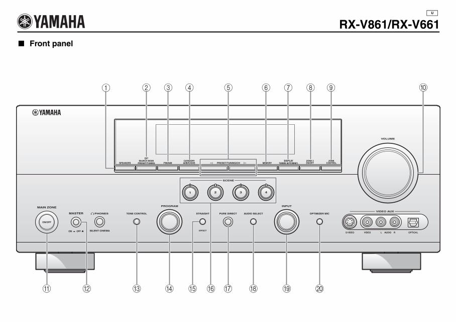
Front panel
RX-V861/RX-V661U
VOLUME
INPUTPROGRAM
SCENE
S VIDEO VIDEO OPTICALL AUDIO R
VIDEO AUX
SEARCH MODE
EFFECT
PURE DIRECTSTRAIGHTPHONES
SILENT CINEMA
ON/OFF
AUDIO SELECTTONE CONTROL OPTIMIZER MIC
1 2 3 4
SPEAKERS PRESET/TUNING
EDIT
FM/AM A/B/C/D/ECATEGORY
MEMORY TUNING AUTO/MAN'LDISPLAY
ON/OFFZONE 2
CONTROLZONE
l PRESET/TUNING/CH h
MAIN ZONE
MASTER
ON OFF
G
1 2 3 4 5 6 7 8 9 0
A C D E HB I JF
00_Sheet_RX-V861_661_U.book Page 1 Friday, December 8, 2006 5:49 PM
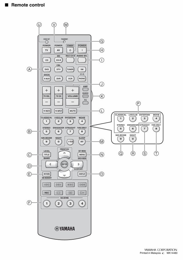
Remote control
REC
SCENE
1 2 3 4
VOLUMETV VOL TV CH
AMP
SOURCE
TV
TRANSMITCODE SET
STANDBY POWERPOWERPOWER
AVTV
MULTI CH IN AUDIO SEL
DOCK
MD
CBL
PHONO
MUTETV MUTE TV INPUT
4321
8
10
7
09
65
SLEEP
MOVIEENTERTAINLIVE/CLUBCLASSICAL
ENT
PURE DIRECTSTRAIGHTSTEREO ENHANCER
NIGHTSUR. DECODE
MENUTITLE
SET MENU
SRCH MODE
XM MEMORY
LEVEL
DISPLAYRETURN
BAND
A-E/CAT.
ENTER
PRESET/CH
CD CD-R
TUNER XM
V-AUX
DVD
DVR VCR
DTV
4321
87
09
65
MOVIEENTERTAINLIVE/CLUBCLASSICAL
PURE DIRECTSTRAIGHTSTEREO ENHANCER
NIGHTSUR. DECODE
G
K
L
M
J
I
H
N
E
F
D
A
B
C
O
P
Q R S T
U V W
WK14480Printed in Malaysiaa
00_Sheet_RX-V861_661_U.book Page i Friday, December 8, 2006 5:49 PM
RX-V661
Page 35 (footnote *2)
Incorrect*2 You can select “V-AUX” as the input source even if your iPod is stationed in the Yamaha Universal Dock connected to this
unit. When the SCENE mode is deactivated and your iPod is stationed in the Yamaha Universal Dock, this unit selects “DOCK” as the input source automatically.
Correct*2 You can select “V-AUX” as the input source even if your iPod is stationed in the Yamaha Universal Dock connected to this
unit.
WK52460Printed in Malaysia
U