02 vetco - marine raiser systems
DESCRIPTION
Marine Riser SystemsChevronTexaco – BP Training AllianceFloating DrillingTRANSCRIPT

Marine Riser SystemsChevronTexaco – BP Training Alliance
Floating Drilling
Marine Riser SystemsChevronTexaco – BP Training Alliance
Floating Drilling

Vetc
o G
ray
-2
CT-D
TC-F
loat
ing-
CD
E.pp
t1
Feb
2004
The design of casing and wellhead systems should be performed with the complete wellhead system – including the riser.
Integrating …Wellhead, BOP and Riser Design
Vetc
o G
ray
-3
CT-D
TC-F
loat
ing-
CD
E.pp
t1
Feb
2004
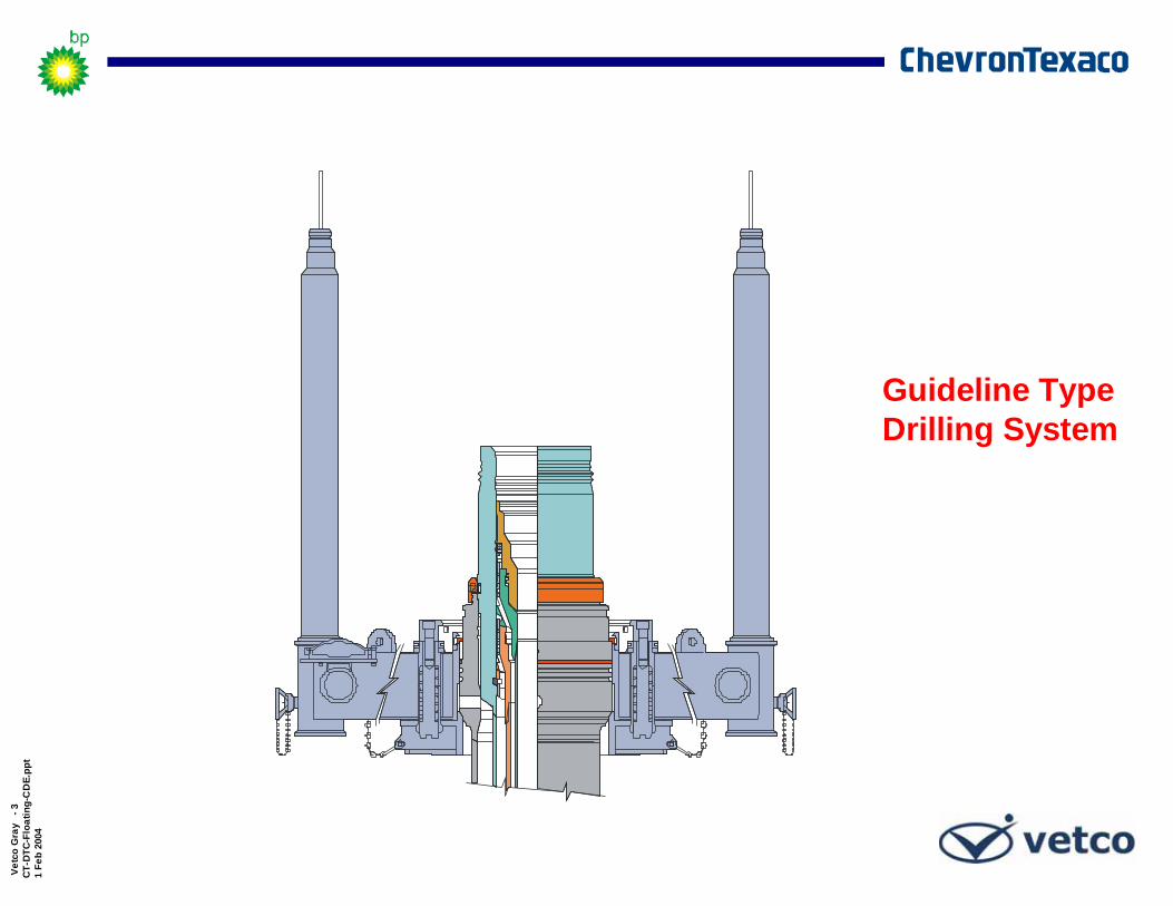
Guideline Type Drilling System

Vetc
o G
ray
-4
CT-D
TC-F
loat
ing-
CD
E.pp
t1
Feb
2004
Connector to Housing Interface
Guidebase/GRA Interface
Housing Interface
Mudmat Interface
Guidelineless Drilling Systems

Vetc
o G
ray
-5
CT-D
TC-F
loat
ing-
CD
E.pp
t1
Feb
2004
MS-700 Family of Wellhead Systems

Vetc
o G
ray
-6
CT-D
TC-F
loat
ing-
CD
E.pp
t1
Feb
2004
H-4 Family of Wellhead Connectors

Vetc
o G
ray
-7
CT-D
TC-F
loat
ing-
CD
E.pp
t1
Feb
2004
BOP and Lower Marine Package
Courtesy of Hydril Company

Vetc
o G
ray
-8
CT-D
TC-F
loat
ing-
CD
E.pp
t1
Feb
2004
Lower BOPw/ Frame
Courtesy of Hydril Company

Vetc
o G
ray
-9
CT-D
TC-F
loat
ing-
CD
E.pp
t1
Feb
2004
Blind -Shear Rams
Upper Pipe Rams
Middle Pipe Rams (Varible)
Lower Pipe Rams
Super Shear Rams
(Varible Bore)
LMRP Mandrel
Annular
Lower BOPw/o Frame
Kill Line
Choke Line
Accumulators (x4)
Courtesy of Hydril Company
Wellhead Connector

Vetc
o G
ray
-10
CT-D
TC-F
loat
ing-
CD
E.pp
t1
Feb
2004
Lower Marine Riser Package
(LMRP)
Courtesy of Hydril Company

Vetc
o G
ray
-11
CT-D
TC-F
loat
ing-
CD
E.pp
t1
Feb
2004
Lower Marine Riser Package
(LMRP)Riser Adapter
Single Flexjoint
Annular
Control Pod(1 of 2)
Mud Boost Line
LMRP Connector (H-4)
Courtesy of Hydril Company
Choke Line Stab

Vetc
o G
ray
-12
CT-D
TC-F
loat
ing-
CD
E.pp
t1
Feb
2004
Funnel Down (Optional)

Vetc
o G
ray
-13
CT-D
TC-F
loat
ing-
CD
E.pp
t1
Feb
2004
Hydrate Protection
GrooveGroove
PN H12025-2 (16-3/4" Wellhead)PN H12025-3 (Super Wellhead)
Fiber Reinforcement
Rubber
Hydrates must be prevented from entering the bottom of the connector. Ice formed from hydrates will prevent the connector from releasing

Vetc
o G
ray
-14
CT-D
TC-F
loat
ing-
CD
E.pp
t1
Feb
2004
Hydrate Protection(Methane Gas)

Vetc
o G
ray
-15
CT-D
TC-F
loat
ing-
CD
E.pp
t1
Feb
2004
ROV Hot StabInlet Thru
Wash Ports
Outlet Thru Wash Ports
Hydrate ProtectionPlum H4 To Inject Freezing Inhibitor
Glycol Inhibitor
Cavity Capacity32 Gallon
SHD H-4 Wellhead Connector

Vetc
o G
ray
-16
CT-D
TC-F
loat
ing-
CD
E.pp
t1
Feb
2004
Type of Well
Exploratory Wells
Disposal
Non-Disposal
Developmental

Vetc
o G
ray
-17
CT-D
TC-F
loat
ing-
CD
E.pp
t1
Feb
2004
DP
Moored
Wellhead Re–Entry Systems

Vetc
o G
ray
-18
CT-D
TC-F
loat
ing-
CD
E.pp
t1
Feb
2004 Subsea Wellhead Angle

Vetc
o G
ray
-19
CT-D
TC-F
loat
ing-
CD
E.pp
t1
Feb
2004
Riser Deployment and Retrieval
Environmental conditions
Location
Season
Vessel
Deployment / Retrieval
Riser fatigue life
Currents

Vetc
o G
ray
-20
CT-D
TC-F
loat
ing-
CD
E.pp
t1
Feb
2004
Riser Handling and Lifting Gear Capacity
Substructure
Derrick
Drawworks
Hook block
Handling gear
Riser Running Tool
Riser Gimble Shock Absorber

Vetc
o G
ray
-21
CT-D
TC-F
loat
ing-
CD
E.pp
t1
Feb
2004
API Riser Coupling ClassAPI RP 2R establishes riser coupling classes based on the tensile capacity of the coupling. These are;
2.5F
4.0J (Proposed)
3.5H
3.0G
2.0E
1.5D
1.25C
1.0B
.5A
Tensile Capacity in millions of pounds
API Riser Coupling Class

Vetc
o G
ray
-22
CT-D
TC-F
loat
ing-
CD
E.pp
t1
Feb
2004
MR-6E Riser CouplingEasy stabbing, fast makeup, and positive alignmentSuitable for operating in water depths up to 7,500 ft depending on environmental and well control conditions; MR-10 designs can operate in depths to 10,000 ft.Preloaded connection significantly reduces the range of alternating stresses induced by cyclic loading to improve fatigue lifePrimary load path for tensile and bending loads through the dogs and into the body, does not impact actuating screws

Vetc
o G
ray
-23
CT-D
TC-F
loat
ing-
CD
E.pp
t1
Feb
2004
MR Riser Running Tool
18o Tapered Drill pipe Connection
4-1/2” IF API Connection
MR Box Connection Profile
Lift / Handling Eye
Choke, Kill & Auxillary Test Caps

Vetc
o G
ray
-24
CT-D
TC-F
loat
ing-
CD
E.pp
t1
Feb
2004
HMF Riser Coupling
Ideal for deep water applications where high load operating conditions existStepped diameter design of pin and box simplifies engagement, even with severe vessel movementNo loose parts preventing bolt loss and potential thread damageField removable and replaceable nose pieceLocking bolts preloaded in excess of rated coupling loads to extend fatigue load of riser system

Vetc
o G
ray
-25
CT-D
TC-F
loat
ing-
CD
E.pp
t1
Feb
2004
HMF Riser Running Tools
Handling Lift Eye
HMF Male Connection Profile
Mechanical Running Tool
Hydraulic Running Tool
Casing Elevator Lift Shoulder

Vetc
o G
ray
-26
CT-D
TC-F
loat
ing-
CD
E.pp
t1
Feb
2004
Riser Handling Tool

Vetc
o G
ray
-27
CT-D
TC-F
loat
ing-
CD
E.pp
t1
Feb
2004
Hydraulic-gate riser spider is used when running or retrieving HMF riser joints through the rotary table.
MR-style riser handling spider supports the riser string on manual or hydraulically operated sliding dogs.
Spider

Vetc
o G
ray
-28
CT-D
TC-F
loat
ing-
CD
E.pp
t1
Feb
2004
Gimbal
Gimbal shock absorber supports up to 2,000,000 lb and gimbals when the riser is positioned in the spider.
Reduces impact loads when running and landing marine riser joints.

Vetc
o G
ray
-29
CT-D
TC-F
loat
ing-
CD
E.pp
t1
Feb
2004
Single Flex Jointwith Mud Boost Line

Vetc
o G
ray
-30
CT-D
TC-F
loat
ing-
CD
E.pp
t1
Feb
2004
Flex JointsSingle Flex Joint & Intermediate Flex Joint

Vetc
o G
ray
-31
CT-D
TC-F
loat
ing-
CD
E.pp
t1
Feb
2004
Riser Extension

Vetc
o G
ray
-32
CT-D
TC-F
loat
ing-
CD
E.pp
t1
Feb
2004
Key Riser Components and Inspection
Prepped for Buoyancy
Drilling Riser

Vetc
o G
ray
-33
CT-D
TC-F
loat
ing-
CD
E.pp
t1
Feb
2004
Installation of Syntactic Foam Buoyancy Moduleson a Riser Joint

Vetc
o G
ray
-34
CT-D
TC-F
loat
ing-
CD
E.pp
t1
Feb
2004
90’ (27.4m) Riser Joint(w/ Spreader Bar)

Vetc
o G
ray
-35
CT-D
TC-F
loat
ing-
CD
E.pp
t1
Feb
2004
Telescopic Joint

Vetc
o G
ray
-36
CT-D
TC-F
loat
ing-
CD
E.pp
t1
Feb
2004
Telescopic Joint
Available for both multiple riser systemsCompensates for heave and offset of the vesselMaximum rated riser tensile load capacity in locked positionHydraulic latch release for inner and outer barrels availableDual split/solid packer elementsFixed or rotating integral/non-integral tensioner ringsSDL, SLS, KT and SDC tensioning rings

Vetc
o G
ray
-37
CT-D
TC-F
loat
ing-
CD
E.pp
t1
Feb
2004
Primary Components of Telescopic Joint
The outer barrel sub assembly has several functions:Providing a means to apply tension to the Marine Riser / BOPFluid assist bearing to allow rig rotationTension ring to eliminate the tensioner wire removalDual packer assemblyKill, choke and Auxiliary line supply assembly
The inner barrel sub assembly functions:Providing communication between the vessel and the BOP during drillingContains an Auto latch system to lock inner/outer barrelSplit lock nut for easy servicingCross-over flange to riser connection and diverter Fully extended can support 1.5m lbs

Vetc
o G
ray
-38
CT-D
TC-F
loat
ing-
CD
E.pp
t1
Feb
2004
Hydraulic Latch
Slipjoint / Telescopic Joint
Split Lock Nut
Inner Barrel
Crossover to Riser Connector
Dual Packer Inner Barrel Latch

Vetc
o G
ray
-39
CT-D
TC-F
loat
ing-
CD
E.pp
t1
Feb
2004
Fluid Assist Bearing
SLS Tension RingKill & Choke & Hydraulic Supply Terminations
Slipjoint / Telescopic Joint
SDL Tension Ring
KT Tension Ring
Options
Options
Options

Vetc
o G
ray
-40
CT-D
TC-F
loat
ing-
CD
E.pp
t1
Feb
2004
Type SDL Riser Support Ring
Saves rig time by eliminating tensionerwire removal
Stored below diverter and allows the rest of the riser to be pulled through
Contains two sets of hydraulic dogs One to latch to diverter for storageThe other to latch to outer barrel while drilling

Vetc
o G
ray
-41
CT-D
TC-F
loat
ing-
CD
E.pp
t1
Feb
2004
The primary function of a diverter is to divert shallow gas through overboard piping before the installation of the BOP stack. This vents the well and protects the formation before it is capable of handling closed-in pressure from the installed BOP. After the BOP is installed it is used to vent gas in the riser, above the BOP.
Diverter System
There are two primary models of Vetco Gray diverters used on floaters:
KFDS – using an expandable rubber packerKFDS- CSO – using a collapsible rubber element
There is one primary model of diverter used on Jack-ups and Platform rigs :
KFDJ – using an expandable rubber packer
Diverters are available in 39-1/2”, 49-1/2” and 60” nominal sizes
Pressure ratings range from 500 to 1000 psi
Hang-off capacities range 500 kips – 2000 kips
In Floater Operations

Vetc
o G
ray
-42
CT-D
TC-F
loat
ing-
CD
E.pp
t1
Feb
2004
KFDS Diverter System
Rotary Table
Control Lines/Block
Insert Packer
Crossover to Riser Connector
Flex Joint
Diverter Assembly
Flowline Seals (x2)
Flowline
DiverterLockingDogs
Diverter Housing
Pressure Rating (Wellbore): 500 PSIDiverter Operating Pressure:
Normal 750 psi ( 52 bar)Maximum 1500 psi (103 bar)

Vetc
o G
ray
-43
CT-D
TC-F
loat
ing-
CD
E.pp
t1
Feb
2004
KFDS Diverter System
Control Lines/Block
Insert Packer
Diverter Assembly
Flowline Seals (x2)
Flowline
DiverterLockingDogs
Diverter Housing
Pressure Rating (Well bore): 500 PSIDiverter Operating Pressure:
Normal 750 psi ( 52 bar)Maximum 1500 psi (103 bar)

Vetc
o G
ray
-44
CT-D
TC-F
loat
ing-
CD
E.pp
t1
Feb
2004
Diverter Assembly
Packer Element
Divert Line
Diverter Flex Joint
Flow Line
CSO Diverter
Vetc
o G
ray
-45
CT-D
TC-F
loat
ing-
CD
E.pp
t1
Feb
2004
W.L.
C
A
B
A
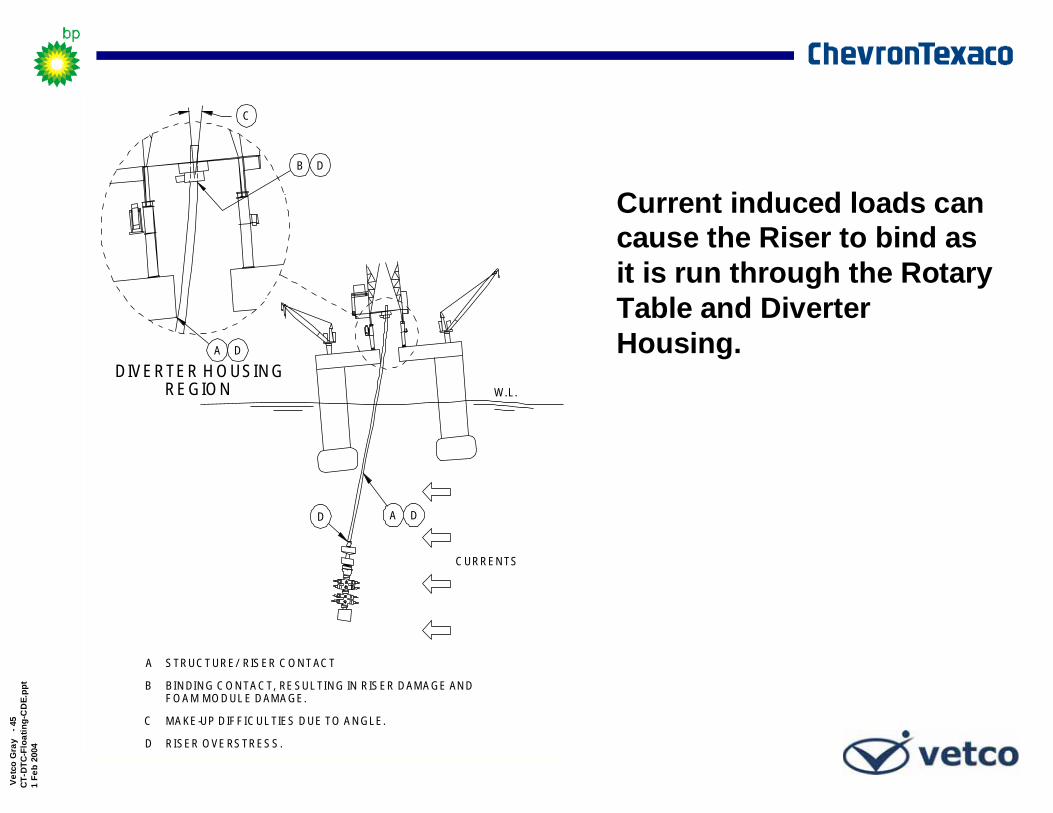
STRUCTURE/RISER CONTACT
BINDING CONTACT, RESULTING IN RISER DAMAGE AND
MAKE-UP DIFFICULTIES DUE TO ANGLE.
RISER OVERSTRESS.
A
B
C
D
FOAM MODULE DAMAGE.
DIVERTER HOUSINGREGION
D
D
D
CURRENTS
D
Current induced loads can cause the Riser to bind as it is run through the Rotary Table and Diverter Housing.

Vetc
o G
ray
-46
CT-D
TC-F
loat
ing-
CD
E.pp
t1
Feb
2004
MUDLINE
WAVE HEAVE
AMPLIFIEDRISER RESPONSE
W.L.
LOADHOOK
DYNAMIC LOAD ON LIFTING GEAR
RATED LIFTING GEAR CAPACITY
NET WEIGHT OF RISER ON
TIME
LIFTING GEAR
HOOK LOAD INDICATOR
Rig lifting equipment must be able to deploy the Riser with the LMRP/BOP Package without exceeding design capacity.
Lifting Equipment

Vetc
o G
ray
-47
CT-D
TC-F
loat
ing-
CD
E.pp
t1
Feb
2004
TENSIONER STROKE
RISER HEAVE ISSOFT HANGOFF,
MINIMIZED BYRISER HEAVES WITH
LMRP
VESSEL
HARD HANGOFF,
W.L.
Stay attached duringstorm conditions
Disconnect the riser and pull out of the hole
Hang-off – Hard or Soft
Storm Hang-off of Riser

Vetc
o G
ray
-48
CT-D
TC-F
loat
ing-
CD
E.pp
t1
Feb
2004
VIV Excitation Due to Currents Vortex shedding due to steady current acting on a pipe results in pipe dynamic motions and fatigue.
⇒ Steady ⇒ Current ⇒ ⇒
Riser Pipe Current-induced Vortices
Wave LoadsEnvironmental Conditions
Riser Fatigue Considerations

Vetc
o G
ray
-49
CT-D
TC-F
loat
ing-
CD
E.pp
t1
Feb
2004
G R E E N
Y E L L O W A L E R T
R E D A L E R T
D IS C O N N E C T C I R C L E
D E G R A D IN G S T A T U S
P R E P F O R E D S
E D S T IM E (A P P R O X .6 0 S E C O N D S )
G R E E N - N O R M A L O P E R A T IO N S
D IS C O N N E C T C IR C L E - E D S C O M P L E T E D , R IS E R
R E D A L E R T - E D S IN IT IA T E D
Y E L L O W A L E R T - P R E P A R E F O R E D S
D IS C O N N E C T E D
V E S S E L O F F S E TF R O M W E L L C E N T E R
Drift-Off/Drive-Off
• Disconnect Speed• Control System
• Riser Tension Recoil• Control of Disconnect

Vetc
o G
ray
-50
CT-D
TC-F
loat
ing-
CD
E.pp
t1
Feb
2004
WAVE ACTION
CURRENTS
MUDLINE
ANGLE
ANGLEMOTIONSVESSEL
W.L.
Limits for Connected Riser Operations

Vetc
o G
ray
-51
CT-D
TC-F
loat
ing-
CD
E.pp
t1
Feb
2004
MUDLINE
ANGLE
ANGLE
OFFSETVESSEL
W.L.
B
D
C
A
RISER
TENSIONERS/TELESCOPIC JOINT
FLEX JOINT
LMRP/BOP
WELLHEAD & CONNECTORSE
CONDUCTOR PIPEF
AC
C
B
D
E
F
POSSIBLE WEAKPOINTS
To prevent failure of Riser/Well System Components, Emergency Disconnect must be completed before vessel offset causes the Riser/Well System to exceed allowable limits.
Riser, Wellheadand Conductor
Strength

Vetc
o G
ray
-52
CT-D
TC-F
loat
ing-
CD
E.pp
t1
Feb
2004
System ObjectiveProvide a system level solution for drilling in ultra deepwater drilling:
BOP FlangeWellhead ConnectorSubsea Wellhead SystemConductor Sizing(Analysis)Conductor/Casing
Connectors
15,000 psi to 20,000 psirated pressure7,000,000 ft.-lbs. Bending @ 15,000 psi
F
~6.6 MM ft-lbs
~7 MM ft-lbs
~7.7 MM ft-lbs
~14 MM ft-lbs(40' Below Mudline)
~8.4 MM ft-lbs
θ
BOP Flange
WellheadConnector
WellheadSystem
Conductor/CasingConnectors
System Considerations

Vetc
o G
ray
-53
CT-D
TC-F
loat
ing-
CD
E.pp
t1
Feb
2004
MUDLINE
LMRP
BOP
W.L.
LMRP MUST MAINTAINCLEARANCE ABOVE BOPSTACK
MUST MAINTAIN CLEARANCEIN TELESCOPIC JOINT
NO SLACK INWIRE ROPES
BOP
LMRP
After riser disconnect, the LMRP must be lifted to prevent contact with the BOP stack during vessel down heave.
Riser RecoilResponse

Vetc
o G
ray
-54
CT-D
TC-F
loat
ing-
CD
E.pp
t1
Feb
2004 MUDLINE
BOP
SEAWATERPRESSURE
PRESSUREMUD
W.L.
Minimal pressure device
Contingency plan for bubble in riser
Riser Burst Pressure

Vetc
o G
ray
-55
CT-D
TC-F
loat
ing-
CD
E.pp
t1
Feb
2004
Gas in Riser vs Choke/Kill Line

Vetc
o G
ray
-56
CT-D
TC-F
loat
ing-
CD
E.pp
t1
Feb
2004
MUDLINE
FROM RISERMUD RELEASE
LMRP
BOP
PRESSURESEAWATER
EMPTYRISER
W.L.
During an emergency disconnect, external pressure from seawater can collapse the Riser if the mud column drops too fast.
Riser Collapse/Riser Fill-Up Valve Placement

Vetc
o G
ray
-57
CT-D
TC-F
loat
ing-
CD
E.pp
t1
Feb
2004
As vessel heading is changed, excessive torque can be applied to the connected drilling riser.
Torque Loads due toHeading Change

Vetc
o G
ray
-58
CT-D
TC-F
loat
ing-
CD
E.pp
t1
Feb
2004
Wellhead with a rigid lockdown mechanism to
enhance fatigue life.
Control Panel
Release Piston Indicator
Power Piston Indicator
Latch to 36”

Vetc
o G
ray
-59
CT-D
TC-F
loat
ing-
CD
E.pp
t1
Feb
2004
Riser Monitoring Systems and Inspection Methods
Daily:Mud weightEnvironmental conditions changeRiser tension and rig location
Long Term:CorrosionCracksWear and DamageChoke and Kill lines

Vetc
o G
ray
-60
CT-D
TC-F
loat
ing-
CD
E.pp
t1
Feb
2004
Benefits from CompositesGeneral
Increased fatigue lifeElimination of corrosion problems
Composite Choke and Kill LinesProvides a 60% weight savings over equivalent steel linesCan save about 25-30% of the total riser string weight, thus extending an existing rig’s drilling depth accordingly
Composite Drilling Riser SystemProvides a 65% weight savings over steel riser systemsCan increase the drilling depth of an existing rig or platformSignificantly reduces the variable deck weight
Composite Production RiserProvides a 60-80% weight savings over equivalent steel risersCan eliminate the need for tensioners on TLPs and SPARsCan increase the number of wells for a given vessel
smaller space requirementsless deck weight
Can increase the water depth for a given production system.

Vetc
o G
ray
-61
CT-D
TC-F
loat
ing-
CD
E.pp
t1
Feb
2004
VGI Composite Products
Harnessing incredibly strong carbon fiber and durable epoxy matrix to produce light-weight oilfield products
Composite products are providing solutions to today’s challenges
Composites enable use of existing rig fleets and production platform designs to go deeper --safer and less expensively.
Choke & Kill LinesDrilling RisersProduction Risers

Vetc
o G
ray
-62
CT-D
TC-F
loat
ing-
CD
E.pp
t1
Feb
2004
$8.4 Million Savings
5,000’ Rig Upgrade to 10,000’
Baseline 5,000’ Water Depth Capable RigAll Steel Riser System (C&K, booster, hydraulic)Nominal 2,000 Kip Tension with 15 ppg Mud46” Diameter BuoyancyDeck Weight of 2.3 M lbsDay Rate of $30k
10,000’ Composite Riser UpgradeSystem Deck Weight 3.55 M lbs5,000’ of Steel Riser Body $2.0 M10,000’ of ALL Aux. Lines $11.7 MAdded 3,000’ of Buoyancy $1.5 M Total $15.2 M
10,000’ Steel Riser UpgradeSystem Deck Weight 5.8 M lbs5,000’ of Full Riser $5.3 M7,200’ of 56” Buoyancy $6.1 M Total $11.4 M
Savings in Upgrades on Rig12 Months of Docked (50%) $5.5 M60” Rotary Table Upgrade $1.5 MRig Buoyancy Upgrade ($2.36/lb) $5.2 M Total $12.2 M
OR
+
Composite System Steel System