02641 - water valves tac · 2021. 2. 8. · astm a126 standard specifications for gray-iron...
TRANSCRIPT

02641 – 1 of 20 Kansas City, Missouri Revised 1/28/21 Water Services Department Standard Specification
SECTION 02641 – WATER VALVES
PART 1 - GENERAL
1.01 SUMMARY A. This section provides valve specifications and installation requirements for all valves
and the associated appurtenances required for the project. B. This section includes: Gate Valves, Butterfly Valves, Air Release Valves, Tapping
Valves, Valve Boxes, Bases, Lids and Covers, Torque Limiting Devices, Valve Seals, Coatings and Check Valves.
1.02 SPECIFICATION MODIFICATIONS A. It is understood that throughout this section these Specifications may be modified by
appropriate items in Section 01015 – Specific Project Requirements or as otherwise indicated on the Contract Drawings.
1.03 RELATED SECTIONS A. Section 01000 – General Project Requirements. B. Section 01015 – Specific Project Requirements. C. Section 01300 – Submittals. D. Section 02250 – Trenching, Pipe Embedment and Backfill. E. Section 03608 – Concrete Vaults. F. Section 05012 – Water Castings.
1.04 CODES AND STANDARDS A. The publications listed below form a part of this specification to the extent
referenced. The publications are referred to within the text by the basic designation only.
B. American Society for Testing and Materials (ASTM): ASTM A48 Standard Specifications for Gray-Iron Castings. ASTM A126 Standard Specifications for Gray-Iron Castings for Valves,
Flanges, and Pipe Fittings. ASTM A276 Standard Specification for Stainless Steel Bars and Shapes. ASTM A536 Standard Specification for Ductile Iron Castings. ASTM A564 Standard Specification for Hot-Rolled and Cold-Finished
Stainless Steel Bars and Shapes. ASTM D47 Standard Test Method for Rubber Property-Effect of
Liquids. ASTM D1149 Standard Test Method for Rubber Deterioration-Surface
Ozone Cracking in a Chamber. C. American Water Works Association (AWWA):
ANSI A21.11/ AWWA C111 Rubber-Gasket Joints for Ductile-Iron Pressure Pipe and Fittings. AWWA C504 Rubber-Seated Butterfly Valves. AWWA C508 Swing-Check Valves for Waterworks Service, 2in. – 24 in. AWWA C509-94 Standard Specification for Resilient Seated Gate Valves for
Water Supply Service.

02641 – 2 of 20 Kansas City, Missouri Revised 1/28/21 Water Services Department Standard Specification
AWWA C512-99 Performance Standards for Air Release, Air/Vacuum, and Combination Air Valves for Water Works Service.
AWWA C515-09 Standard Specification for Reduced Wall Resilient Seated Gate Valves for Water Supply Service.
AWWA C153 Standard Specification for Ductile Iron Watermain Fittings.
1.05 MATERIALS PROVIDED BY THE CITY A. Valves and appurtenances to be provided by the City shall be as indicated in Section
01015 – Specific Project Requirements.
1.06 SUBMITTALS A. Submit as specified in Section 01300 – Submittals. B. Shop Drawings:
1. Detailed drawings, data and descriptive literature on all valves and appurtenances; including, but not limited to, the following: (a) Manufacturer. (b) Dimensions . (c) Size. (d) Specification for materials of construction. (e) Weight. (f) Protective coating. (g) Actuator weight and turns to operate where applicable. (h) Calculations for actuator torque where applicable. (i) Proof of design tests in accordance with AWWA C504, Section 5 –
Verification. Tests shall include the following: (i) Hydrostatic test. (ii) Actuator proof of design testing. (iii) Test valve rehabilitation. (iv) Certification for proof of design.
(j) Cross section drawings detailing all components. (k) Exploded assembly drawings. (l) Parts list.
2. The Contractor shall submit descriptive literature describing the proposed valves and accessories. Contractor shall also furnish a copy of the manufacturer’s warranty that applies to the valves and actuators. See part E. and Part 1.11 of this Section.
C. Product Data: 1. Gate Valves:
(a) Provide catalog data, including illustration and a parts list that identify the materials used for various parts. The information shall be in sufficient detail to serve as a guide in the assembly and disassembly of the valve and for ordering repair parts.
(b) Provide manufacturer’s drawings showing the principal dimensions, construction detail, and materials used for valve parts.
D. Other Submittals: 1. Furnish the Butterfly Valve manufacturer’s warranty that applies to the valves
and actuators being proposed. The warranty period shall be for a minimum of three years after substantial completion of the contract under which the valve is installed or twenty years from the date of shipment, whichever comes first.

02641 – 3 of 20 Kansas City, Missouri Revised 1/28/21 Water Services Department Standard Specification
2. Furnish the Gate Valve manufacturer’s warranty. See Paragraph 1.10 of this Section.
3. Furnish Affidavits of Compliance from the Butterfly Valve manufacturer and Gate Valve manufacturer.
4. Additional Affidavit of Compliance for Coatings: Submit affidavit(s) of compliance associated with the painting of the interior and exterior of the valves.
1.07 QUALITY ASSURANCE A. The Contractor is responsible for the quality assurance and quality control of the
Work. B. Manufacturer:
1. Valves shall be manufactured by a company specializing in the regular production of the Products specified herein and proven reliable in similar service for at least five (5) years.
2. All valves of the same type shall be the product of one (1) manufacturer.
1.08 PRODUCT DELIVERY, STORAGE AND HANDLING A. Follow the provisions for the delivery, storage, protection and handling of products to
the site and on-site provided in Section 01000 – General Project Requirements. B. Butterfly Valves:
1. All other requirements of AWWA C504 Section 6.2 "Shipping" shall apply. Requirements include, but are not limited to, the following: (a) Cavities: The manufacturer shall prepare valves for shipment by draining all
valve cavities. (b) Fastening requirements: Valves larger than 36 in. (900 mm) shall be bolted
or otherwise fastened to skids. Each valve shall be fastened to and delivered on an individual pallet on 4” x 4”, or heavier, wood skids, high enough to protect the valve and actuator
(c) Surfaces: Uncoated steel and iron-machined surfaces shall be coated with a corrosion inhibitor.
(d) Flange protection: Full-face flange protectors of metal, waterproof plywood, or weather-resistant pressboard, of at least the outside diameter of the flange, shall be fastened to each flange to protect both the flange and the valve interior.
(e) Small valves: Small valves may be fully packaged at the manufacturer’s option.
(f) Valve components: Components shipped unattached shall be adequately protected and identified for correct field assembly.
1.09 INFORMATION TO BE SUBMITTED WITH BID A. Butterfly Valves:
1. Descriptive Literature: The Bidder shall include literature describing the valves and actuators to be furnished.
2. Warranty: The Bidder shall furnish three copies of the manufacturer’s warranty that applies to the valves and actuators proposed for the Work. The warranty shall meet the requirements of paragraph WARRANTIES below.

02641 – 4 of 20 Kansas City, Missouri Revised 1/28/21 Water Services Department Standard Specification
3. The Contractor’s selection of butterfly valve manufacturer will be approved as part of the Bid process. Changes to information submitted with the Bid will not be allowed unless otherwise approved.
4. Butterfly valves and actuators that do not meet the minimum requirements of this specification may constitute a non-responsive bid.
5. Failure to provide the requested information with the Bid may constitute a non-responsive bid.
1.10 WARRANTIES A. Gate valves:
1. The manufacturer shall warranty that all gate valves provided for the Project will be free from defects in material and workmanship.
2. The warranty period shall be for a minimum of three years after substantial completion of the Contract under which the valve is installed, or twenty (20) years from the date of shipment, whichever comes first.
3. Submit in accordance with paragraph SUBMITTALS manufacturer’s warranty for all butterfly valves provided. Warranty documentation shall include the date of shipment and unique serial number for each valve.
B. Butterfly valves: 1. The manufacturer shall warranty that all butterfly valves and actuators provided
for the Project are free from defects in material and workmanship. 2. The warranty period shall be for a minimum of three years after substantial
completion of the Contract under which the valve is installed, or twenty (20) years from the date of shipment, whichever comes first.
3. Submit in accordance with paragraph SUBMITTALS manufacturer’s warranty for all butterfly valves provided. Warranty documentation shall include the date of shipment and serial number for each valve.
PART 2 - PRODUCTS
2.01 GENERAL A. Marking and identification of valves shall conform to AWWA C504 or AWWA
C509/C515.
2.02 GATE VALVES A. Approved gate valve manufacturers:
1. Clow. 2. Mueller. 3. M&H. 4. AVK. 5. EJ
B. Gate valves shall be used on all water mains 12-inches and smaller. C. Except as modified or provided herein, all gate valves shall be 200 psi, ductile iron
body, resilient-seated, tight closure gate valves with non-rising stems conforming to the requirements of AWWA C509/C515. AWWA C515 Reduced-wall valves shall have a body and flange thickness/depth equal to or greater than AWWA C153.

02641 – 5 of 20 Kansas City, Missouri Revised 1/28/21 Water Services Department Standard Specification
D. Valve Ends: 1. Mechanical Joint or Push-on Joint: Conforming to ANSI A21.11/AWWA C111
except where flange ends are required. Flanges shall be uniform in thickness/depth, thinning of flange face between bolt locations is prohibited. All glands shall be ductile iron.
2. Flanged: Conforming to the dimensions and drilling of ANSI B16.42 for ductile iron flanges and flange fittings, Class 150. The laying lengths of the flange valves shall conform to the dimensions of ANSI B16.42.
E. Valve Gate: 1. Wedge type gate with a minimum 3/8-inch thick resilient rubber, urethane
rubber, Buna “N” or SBR rubber bonded to or mechanically attached to one side or both sides of the gate.
2. No sliding or shear is permitted on the resilient seat, when compressed to a drop-tight shut-off.
F. Fasteners: All exterior bolts and nuts shall be ASTM A276 Type 304 or Type 316 stainless steel.
G. Operating Nut: The valve shall be equipped with a two-inch square operating nut produced from a material that is corrosion resistant (stainless steel, bronze, etc.) and has a minimum yield strength of 40 KSI. Operating nut shall have a flanged base upon which shall be cast the word OPEN and an arrow indicating the direction to open. The operating nut shall be securely pinned to the actuator shaft using a corrosion resistant (stainless steel, bronze, etc.) fastener.
H. Valve Stems: The gate valve stems shall be produced from a material that is corrosion resistant to potable water and has a minimum yield strength of 40 KSI.
I. Seals: Gate Valves shall be provided with stem seals of the “O” ring type. Two “O” rings shall be used with at least one “O” ring inserted above the thrust collar. The packing plate shall be attached to the valve bonnet by not less than two (2) bolts if bolts are required and one “O” ring below the thrust collar.
J. Coatings: All exterior surfaces of each valve shall be cleaned and painted in the shop with two (2) coats of asphalt varnish conforming to Federal Specifications TT-V-51-E. The interior surface shall have a protective coating of fusion-bonded, non-toxic epoxy that is safe for potable water. Non-toxic epoxy may also be used for exterior coating.
K. Tapping Valves: The valves shall be 200 psi, ductile iron body, resilient-seated, tight closure gate valves with non-rising stems in conformance with AWWA C509/C515, except that the outlet end shall be a standard mechanical joint end conforming to ANSI A21.11/ AWWA C111 and the inlet end shall have an inlet flange conforming to ANSI B16.42 for ductile iron flanges, Class 150. Gland shall be ductile iron.
2.03 BUTTERFLY VALVES A. Approved butterfly valve manufacturers:
1. M&H. 2. Dezurik. 3. VSI.
B. Butterfly valves shall be used on all mains 16-inches and larger. C. Affidavit of Compliance:
1. For each butterfly valve or appurtenance provided as part of the Contract, the Contractor shall submit the manufacturer’s affidavit of compliance.

02641 – 6 of 20 Kansas City, Missouri Revised 1/28/21 Water Services Department Standard Specification
2. The affidavit shall certify that each butterfly valve or appurtenance meets the minimum requirements of the specifications.
3. Affidavits shall be printed on the manufacturer's letterhead and signed by responsible officials of the manufacturer attesting that the product meets specification requirements.
4. The affidavit must be dated after the award of the contract. D. Butterfly valves shall comply with AWWA C504 and as specified herein:
1. Butterfly valves shall be rubber-seated. 2. Size: 16-inches through 72-inches in diameter. 3. Operating pH Range: 6 to 12. 4. Operating temperature range: 33º to 125ºF. 5. Maximum steady-state fluid working pressure: 250 psig. 6. Maximum steady-state differential pressure: 250 psi. 7. Maximum full open fluid velocity: 16 ft./sec (based on nominal valve size).
E. Body Type: 1. Vault Installation:
(a) Short Body, Flanged Valves. (b) Material: Ductile Iron cast to full gray cast iron thickness. (c) Class 150B for sizes 16-inches through 72-inches. (d) Class 250B in sizes 16-inches through 48-inches.
2. Direct Bury Installation: (a) Short Body, Mechanical-Joint-End Valves. (b) Material: Ductile Iron cast to full gray cast iron thickness. (c) Class 150B and Class 250B for sizes 16-inches through 24-inches. (d) Class 150B and 250B for sizes 30-inches through 48-inches.
F. Actuators for Butterfly Valves: 1. Limitorque Model HBC series. 2. Auma Model GS series.
G. Torque Limiting Devices: 1. Model D86 Overtorque Protector Model D86 as manufactured by Aunspach
Controls Company, Inc. H. Interior Coatings for Valves 54-inches and greater:
1. Tnemec N141. I. Exterior Coatings for Valves 54-inches and greater:
1. Tnemec N141. J. The valves and actuators shall be of the latest model with all standard accessories
ordinarily furnished to the industry except as otherwise specified herein. K. All valves of one size shall be built by one manufacturer with actuators built by one
manufacturer. L. Serial Number: Each valve shall have a unique serial number, which shall be part of
the information on the tag specified in paragraph MARKING REQUIREMENTS. M. Marking Requirements:
1. Markings shall be cast on the body with raised letters or provided on a plate. 2. Plates shall be corrosion-resistant and shall conform to ASTM A276 Type 304 or
Type 316 stainless steel. 3. At a minimum, the markings shall show the following information:
(a) Valve size. (b) Manufacturer. (c) Class.

02641 – 7 of 20 Kansas City, Missouri Revised 1/28/21 Water Services Department Standard Specification
(d) Year of manufacture. (e) Unique serial number. (f) The position of the valve seat in the valve body shall be marked on the
outside of the valve body, within 12 inches of the actuator nut of upper valve trunnion, tagged or cast, in ¼-inch high print, “SEAT THIS SIDE.”
(g) Number of turns to fully open or close the valve. 4. If the design is such that there is a preferred seating direction, the seating
direction shall be marked. 5. Lettering Dimensions:
(a) Cast letters: ½-inch minimum. (b) Plate letters: ⅛-inch minimum. Letters shall be etched or engraved.
N. The quantity, pressure rating, valve material type, and size of each valve shall be as indicated on the Drawings.
O. Design: All valve parts shall be designed for a minimum safety factor of 3 based on yield strength, or a safety factor of 5 if based on tensile strength.
P. Flow Coefficient: 1. The flow coefficient in terms of velocity head (K), in the full open position, shall
not be greater than indicated in Table 1:
Table 1 - Maximum Allowable Flow Coefficients (K)
Valve Size
Valve Pressure Rating
75 psi 150 psi 250 psi
16-inch through 24-inch 0.40 0.45 0.55
30-inch through 48-inch 0.40 0.40 0.50
54-inch through 72-inch 0.40 0.40 --- 2. Pressure measurements shall be made at two pipe diameters upstream of the
valve and eight pipe diameters downstream of the valve in accordance with recommended procedures of ASME Report on Fluid Meters, Latest Edition.
Q. Minimum Port Diameter: The minimum port diameter through the valve shall not be less than indicated in Table 2:
Table 2 – Minimum Allowable Port Diameter
Nominal Valve Size (inches)
Allowable Difference in
Diameter (inches)
16 through 42 1
48 through 54 1 ¼
60 through 72 1 ½

02641 – 8 of 20 Kansas City, Missouri Revised 1/28/21 Water Services Department Standard Specification
R. Fasteners: All bolts and nuts inside and outside the valve, except Mechanical Joint bolts and nuts, shall be ASTM A276 Type 304 or Type 316 stainless steel or ASTM A564 Grade 630 stainless steel.
S. Valve Body: The valve body shall be ductile iron poured to full gray iron thickness. T. End Plate: No bolt or end thrust adjusting screw shall extend through the End Plate. U. End Connections:
1. The dimensions and drillings of end flanges shall conform to ANSI B16.42 for 75 psi valves, ANSI B16.42 Table 5 for 150 psi valve and 250 psi valves, both with 150 psi drillings.
2. If specified or shown on the Drawings, 250 psi dimensions and drillings of end flanges shall conform to ANSI B16.42 Table 8, to include but not be limited to, flange outside diameter, flange thickness, bolt circle diameter, bolt diameter, and bolt quantity.
3. The mechanical joint valves are to include the following accessories: gaskets, ductile iron gland rings, mechanical joint bolts, and nuts.
V. Shafts: 1. All valve shafts shall be in accordance with AWWA C504 Table 3 unless
otherwise amended herein. 2. All valve shafts, dowels, and taper pins shall be ASTM A276 Type 304 or Type
316 stainless steel or ASTM A564 Grade 630 condition H1100 stainless steel. 3. The valve shaft shall have a means of clearly indicating the position of the disc
on the actuator end of the shaft. This mark shall be machine grooved and shall be visible when the cover and lubrication are removed and shall be offset to the same side as the disc.
4. The valve shaft shall be completely enclosed between the valve body and the actuator body.
W. Valve Disc: The valve disc shall be ductile iron and shall seat perpendicular to the centerline axis of the valve body.
X. Valve Seats: 1. The resilient seat shall be EPDM synthetic rubber applied to the valve disc. 2. The resilient seat shall be mechanically secured to either the valve disc or valve
body with ASTM A276 Type 304 or Type 316 stainless steel fasteners or non-bonding epoxy.
3. Resilient seats shall be field adjustable and replaceable without special tools or instruction.
4. Mating surfaces for the valve seats shall be ASTM A276 Type 304 or Type 316 stainless steel.
5. All seats shall be designed to provide tight shut-off with flow in both directions. Y. Shaft Seals:
1. Seal shall be provided by the use of standard V-type packing or standard “O” ring seals; pull-down packing is not acceptable.
2. The valve shall be designed so that the actuator may be removed and replaced while the valve is in service without losing water.
Z. Actuator: 1. The actuator shall be a link lever traveling nut type, worm gear type, or yoke and
nut type and shall be capable of withstanding submersion in water to a pressure of 10 psi.
2. All exposed bolts, nuts, and shafts shall be of ASTM A276 Type 304 or Type 316 stainless steel or ASTM A564 Grade 630 condition 1100 stainless steel.

02641 – 9 of 20 Kansas City, Missouri Revised 1/28/21 Water Services Department Standard Specification
3. All actuators shall have outside mechanical adjustments capable of adjusting valve travel without removing the valve from the pipeline or removing the actuator cover.
4. Direction of Operation: (a) Buried service valves shall open right (clockwise). (b) Vault service valves shall open left (counterclockwise).
5. Operating Nut: The actuator shall be equipped with a two-inch square operating nut produced from a material that is corrosion resistant (stainless steel, bronze, etc.) and has a minimum yield strength of 40 KSI. The operating nut shall have a flanged base upon which shall be cast the word OPEN and an arrow indicating the direction to open. The operating nut shall be securely pinned to the actuator shaft using a stainless steel fastener.
6. Handwheels: For vault service valves, the actuator shall be supplied with a handwheel. The handwheel shall be no smaller in diameter than 30 inches and no larger in diameter than 36 inches. Manual actuators shall be suitable for future adaptation to motor operation. Vault service actuators shall have an indicator on the exterior of the actuator indicating the valve disc position. This indicator shall be stainless steel.
7. All gearing and actuator stops shall be enclosed in a suitable housing with a removable cover to permit inspection, repair, and adjustment of the mechanism.
8. Adjustable stop limiting devices shall be provided inside the actuator housing to stop the input shaft at full open and full closed positions. The use of stop nuts or shaft collars which rely on clamping forces or set screws to prevent rotation of the nut or collar on the screw shaft will not be acceptable.
9. The actuator shall rotate the disc from full open to full closed and vice-versa using not less than, nor more than, the number of turns indicated in Table 3:
Table 3 – Minimum and Maximum Turns for Butterfly Valves
Valve Size (inches)
Minimum Turns
Maximum Turns
16 30 60
20 40 80
24 40 80
30 40 200
36 80 200
42 80 220
48 90 300
54 90 700
60 200 700
72 200 700
90 200 700

02641 – 10 of 20 Kansas City, Missouri Revised 1/28/21 Water Services Department Standard Specification
AA. Painting Interior of Valves: 1. The interior of valves sizes 16-inch through 72-inch shall be coated with a white,
NSF 61 certified, fusion-bonded or powder coated epoxy. 2. Surface preparation and application shall be in accordance with SSPC PA-1. 3. The dry film thickness of the coating shall be a minimum of 10 mils.
BB. Painting Exterior of Valves: 1. The exterior of valve sizes 16-inch through 48-inch shall be coated with an NSF
61 certified, fusion-bonded or powder coated epoxy. 2. The exterior of valve sizes 54-inch through 70-inch shall be coated with an epoxy
paint. 3. Surface preparation and application shall be in accordance with SSPC PA-1. The
dry film thickness of the coating shall be a minimum of 10 mils. CC. Factory Inspections:
1. The City’s representative shall witness the performance, leakage and hydrostatic tests as prescribed in AWWA C504, Section 5 – Verification. Factory tests shall be conducted at the Manufacturer's facility.
2. The City’s representative will inspect all valves provided as part of the Contract for conformance to the Contract Documents.
3. No valve shall be shipped from the manufacturer’s facility until it passes the factory inspection to the satisfaction of the City.
4. All costs associated with the factory inspection shall be included in the Bid. The Contractor (or valve manufacturer) shall pay all expenses for transportation, lodging, and meals required by the City’s representative to complete the inspection. Absolutely no expenses are to be paid by the City’s representative at any time. All transportation and lodging shall be subject to approval by the City.
5. The Contractor shall coordinate with the City’s representative regarding the schedule for the factory inspection. The inspection date and time shall be approved by the City.
6. The need for multiple factory inspections is at the discretion of the Contractor (or valve manufacturer.) The costs to conduct multiple inspections, or to reschedule a factory inspection, shall be included in the Bid and shall be conducted at no additional cost to the City.
DD. Post-Delivery Inspections: 1. After the valves are delivered, the City may again test the valves and actuators
for compliance with the Contract Documents. 2. Any valve that does not meet specifications or fails testing will be considered
defective work, and shall be addressed in accordance with Section 00700 – General Conditions, Article 13 – Tests and Inspection; Correction, Removal or Acceptance of Defective Work.
3. The Contractor shall also be responsible for all testing expenses incurred by the City for all valves that fail to perform as specified herein.
EE. Torque Limiting Devices: 1. Contractor shall provide a Torque Limiting Device for each direct-bury butterfly
valve as specified herein. 2. The torque limiting device shall make over-torque, in either direction,
impossible. The unit shall be preset and designed to release when the torque level exceeds 210 foot pounds on the operating nut, in either direction, OPENING or CLOSING the valve. The torque unit shall reset automatically when the torque level drops below 200 foot pounds on the operating nut in either direction.

02641 – 11 of 20 Kansas City, Missouri Revised 1/28/21 Water Services Department Standard Specification
3. The torque level of the unit shall be adjustable so it may be field set to release at a desired torque limit.
4. The unit shall be less than 5-1/4 inches in diameter and made to mount on the valve inside of the 6-inch diameter stem riser tube of the valve box or in the valve box.
5. The unit shall be provided with a two-inch AWWA operating nut, securely attached to the device. The nut shall have an arrow on the base indicating the valve opens to the “RIGHT” (clockwise) and the word “OPEN”. The unit shall be provided with a two-inch square tapered AWWA socket securely attached to the device. The socket shall fit a 2-inch AWWA nut.
6. The unit shall be designed to withstand submersion in water to a pressure of 10 psi; to endure long periods (years) of active or inactive use buried underground and submerged in water. The unit shall be sealed to prevent water and direct from entering the mechanism. The unit shall be packed with a suitable grease.
7. All housing parts, including nut and socket, shall be coated inside and outside with catalyzed (2-part) epoxy. A top coat of catalyzed (2-part) polyurethane enamel shall be applied over the epoxy for additional hardness and extra corrosion protection.
8. Contractor shall mount the torque limiting device’s integral socket on each butterfly valve’s 2-inch AWWA operating nut inside of the stem riser tube before backfilling around the valve. No fasteners or screws shall be used to secure the torque limiting device to the operating nut.
2.04 AIR RELEASE VALVES AND COMBINATION VALVES A. Approved manufacturer:
1. ARI Flow Control Accessories. B. Air Release Valves:
1. Air release assemblies shall be manufactured in accordance with AWWA C512 performance standards.
2. All piping shall be brass pipe except the air outlet from the air release valve that shall be brass or copper tubing. Brass piping shall be ASTM B43, Extra Strong with ASME 816.1 Class 250 fittings.
C. Air Release Valves for mains 12-inches in diameter or smaller shall be 3/4-inch in Diameter unless otherwise specified. 1. Isolation valves shall be ¾-inch stainless steel ball valves, 150 psi working
pressure. 2. Air release valves shall be installed in accordance with Drawing No. 02641-1. 3. Provide vault cover with minimum one 1-inch diameter hole for air flow.
D. Combination Air Release Valves for mains larger than 12-inches in diameter: 1. The contractor shall submit to ARI Flow Control Accessories the bid documents
so ARI may perform a sizing and placement analysis to verify the placement and sizing of the valves specified during the design of the waterline.
2. Isolation valves shall be 2 inch stainless steel ball valves with screwed, non-rising stems, 175 psi working pressure or wafer style BFV with handwheel or lever operator.
3. Air release valves shall be installed in accordance with Drawing Nos. 02641-2 and 02641-2B.
4. Provide vault cover with a minimum of four 1-inch diameter holes for air flow.

02641 – 12 of 20 Kansas City, Missouri Revised 1/28/21 Water Services Department Standard Specification
E. Air Release Valves for mains 12-inches in diameter or smaller shall be 3/4-inch in diameter unless otherwise specified: 1. Model S-050 as manufactured by ARI Flow Control Accessories.
F. Combination Air Release Valves shall be used for mains larger than 12-inches in diameter: 1. Model D-040 Combination Air Release Valve 2-inch as manufactured by ARI
Flow Control Accessories. 2. Model D-060 Combination Air Release Valve 3-inch and larger as manufactured
by ARI Flow Control Accessories.
2.05 VALVE BOXES AND BASES A. Approved manufacturers:
1. Ametek. 2. MacLean Highline. 3. Pentek Access Boxes.
B. All valve boxes and bases shall be one-piece only. C. One-piece valve boxes and bases shall be injection molded plastic conforming to
ANSI/ASTM 2853, Class 1212.
2.06 VALVE BOX LIDS AND COVERS A. Approved manufacturers and models shall be in accordance with this section and
section 05012 – Water Castings. B. Approved manufacturers:
1. Clay & Bailey. 2. Sigma Municipal Castings. 3. Star Pipe Products. 4. EJ. 5. MacLean Highline. 6. Pentek Access Boxes.
C. The approved manufacturers shall submit their model in accordance with this Section and Section 01300 – Submittals for review and approval.
2.07 CHECK VALVES A. Approved manufacturers:
1. Kennedy Valve. 2. ValMatic.
B. Check valves shall be ductile iron body with reinforced Buna-N rubber flapper. C. Check Valves shall be rated for 250 psi working pressure, 500 psi hydrostatic test for
structural soundness. D. Check Valves shall have ANSI 16.42 – Class 150 flanged end connections. E. The check valve body shall have full flow equal to nominal pipe diameter at all
points in the valve. The valve body shall be of ductile iron construction to ASTM-A-536-65-45-12. Castings shall be clean, sound and without defects. No plugging or welding of such defects will be allowed. The seating surface will be at a 45 degree angle to minimize water hammer.
F. Rubber Clapper & Hinge shall be constructed of ductile iron to ASTM-A 536-65-45-12. Both Clapper and hinge shall have permanently bonded Buna-N rubber with a metal reinforcement connecting the hinge to the clapper.

02641 – 13 of 20 Kansas City, Missouri Revised 1/28/21 Water Services Department Standard Specification
G. The top cover plate will be of ductile iron to ASTM-A536-65-45-12 and must be of full size to allow removal of the disc without removing the valve from line. All exterior nuts and bolts shall be 304 or 316 stainless steel.
H. All iron parts inside and out will be fusion bonded epoxy coated. All coatings must be NFS-61 approved for use in drinking water systems.
I. Vault service check valves shall have an external mechanical position indicator.
2.08 VAULTS A. Concrete vaults shall conform to Section 03608 – Concrete Vaults.
PART 3 - EXECUTION
3.01 INSPECTION A. Each valve shall be inspected before installation to ensure that all foreign substances
have been removed from within the valve body. B. Valves shall be opened and closed to see that all parts are in required working
condition.
3.02 SETTING VALVES A. All valves and fittings shall be set and jointed in the manner specified herein. The
valves shall be set vertical in the horizontal pipeline. All valves shall be anchored directly to adjacent tees or crosses.
B. One-piece valve box and base or a two-piece valve box and valve base shall be installed on all valves. An approved valve box alignment device shall also be installed in all valve boxes. Install in accordance with Standard Detail No. 02641-4 – Actuator Nut Extension.
C. Valve covers, bases, and lids shall be supported and maintained, centered and plumb over the actuator nut. Cover shall be flush with the roadway or ground surface or at such other as directed by the City.
3.03 AIR RELEASE VALVES A. Air release valves shall be installed in accordance with the following Standard
Details: 1. Mains 12-inches and smaller:
(a) Standard Detail No. 02641-1 – Typical Air Release, 12” Mains and Smaller. 2. Mains 16-inches and larger:
(a) Standard Detail No. 02641-2 – Typical Air Release, 16” Mains and Larger. (b) Standard Detail No. 02641-2a – Typical Air Release, 3” ARVs & CAVs,
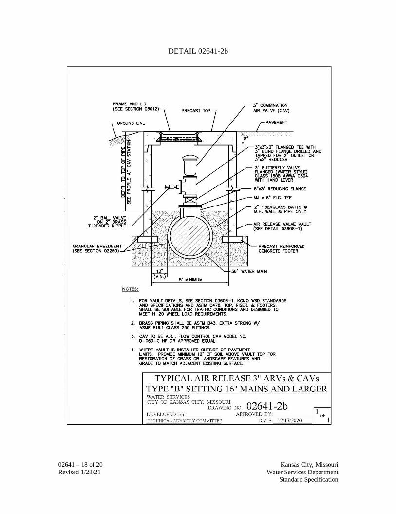
Type “A” Setting, 16” Mains and Larger. (c) Standard Detail No. 02641-2b – Typical Air Release, 3” ARVs & CAVs,
Type “B” Setting, 16” Mains and Larger.
3.04 BUTTERFLY VALVES A. Install in accordance with Standard Detail No. 02641-3 –Typical Butterfly Valve
Installation.

02641 – 14 of 20 Kansas City, Missouri Revised 1/28/21 Water Services Department Standard Specification
3.05 QUALITY CONTROL A. Leak Tests for Butterfly Valves:
1. Each valve shall be shop tested in both directions for leaks in the closed position. The test shall be conducted with the body in a horizontal plane.
2. Air pressure shall be applied to the lower face of the disc for 5 minutes. 3. Both 150-psi and 250-psi rated valves shall be leak tested to 250-psi pressure. 4. The upper surface of the valve disc shall be visible and covered with a pool of
water at "O" psi pressure. There shall be no leakage past the valve disc. Bubbles will appear in the water on the disc if it is leaking.
5. The valve body shall be tested with an internal hydrostatic pressure equivalent to two times the specified shutoff pressure. There shall be zero leakage during the test through the casting, the end joints or the shaft seals. Any part damaged by the Manufacturer’s factory testing shall be replaced or a new valve provided.
6. The hydrostatic test period for 4-inch valve bodies through 20-inch bodies shall be at least 3 minutes. Valve body’s 24-inch and larger shall be tested for at least 10 minutes.
B. Operational Test for all valves: 1. Prior to installation, each valve shall be operated three times from the fully
closed to the fully open position and vice versa. 2. Each valve shall also be tested in the same manner following installation.
THE FOLLOWING SIX PAGES CONTAIN TYPICAL INSTALLATION DETAILS

02641 – 15 of 20 Kansas City, Missouri Revised 1/28/21 Water Services Department Standard Specification
DETAIL 02641-1

02641 – 16 of 20 Kansas City, Missouri Revised 1/28/21 Water Services Department Standard Specification
DETAIL 02641-2

02641 – 17 of 20 Kansas City, Missouri Revised 1/28/21 Water Services Department Standard Specification
DETAIL 02641-2a
02641 – 18 of 20 Kansas City, Missouri Revised 1/28/21 Water Services Department Standard Specification
DETAIL 02641-2b

02641 – 19 of 20 Kansas City, Missouri Revised 1/28/21 Water Services Department Standard Specification
DETAIL 02641-3

02641 – 20 of 20 Kansas City, Missouri Revised 1/28/21 Water Services Department Standard Specification
Detail 02641-4
END OF SECTION