03 technical guide emc compliant installation
TRANSCRIPT

8/6/2019 03 Technical Guide EMC Compliant Installation
http://slidepdf.com/reader/full/03-technical-guide-emc-compliant-installation 1/44
ABB drivesEMC compliant installation and
configuration for a power drive system
T e ch ni c
al g ui d e
N o. 3

8/6/2019 03 Technical Guide EMC Compliant Installation
http://slidepdf.com/reader/full/03-technical-guide-emc-compliant-installation 2/44 2 Technical guide No. 3 - EMC compliant installation and configuration for a PDS

8/6/2019 03 Technical Guide EMC Compliant Installation
http://slidepdf.com/reader/full/03-technical-guide-emc-compliant-installation 3/44
© Copyright 2008 ABB. All rights reserved.
ABB drivesEMC compliant installation and
configuration for a power drive system
Technical guide No. 3
3AFE61348280 REV D
EFFECTIVE: 11.4.2008

8/6/2019 03 Technical Guide EMC Compliant Installation
http://slidepdf.com/reader/full/03-technical-guide-emc-compliant-installation 4/444 Technical guide No. 3 - EMC compliant installation and configuration for a PDS

8/6/2019 03 Technical Guide EMC Compliant Installation
http://slidepdf.com/reader/full/03-technical-guide-emc-compliant-installation 5/445Technical guide No. 3 - EMC compliant installation and configuration for a PDS
Contents
Chapter 1 - Introduction .......................................................................... 7
General .......................................................................................................... 7
Purpose of this guide ..................................................................................... 7
Directives concerning the drive ....................................................................... 7
Who is the manufacturer? .............................................................................. 7
Manufacturer’s responsibility ........................................................................... 7
OEM customer as a manufacturer .................................................................. 8
Panel builder or system integrator as a manufacturer...................................... 8
Defi nitions ...................................................................................................... 8
Practical installations and systems .................................................................. 8
Earthing principles .......................................................................................... 9Product-specifi c manuals ............................................................................... 9
Chapter 2 - Definitions .......................................................................... 10
Electromagnetic Compatibility (EMC) of PDS ................................................ 10
Immunity ...................................................................................................... 10
Emission ...................................................................................................... 10
Power drive system ...................................................................................... 11
Types of equipment ...................................................................................... 12
Components or sub-assemblies intended for incorporation 12
into an apparatus by the end users .............................................................. 12Components or sub-assemblies intended for incorporation 12
into an apparatus by other manufacturers or assemblers 12
Finished appliance ........................................................................................ 13
Finished appliance intended for end users .................................................... 13
Finished appliance intended for other manufacturer or assembler 13
Systems (combination of fi nished appliances) ............................................... 14
Apparatus .................................................................................................... 14
Fixed installation ........................................................................................... 14
Equipment .................................................................................................... 14
CE marking for EMC..................................................................................... 14Installation environments .............................................................................. 15
First environment .......................................................................................... 15
Second environment .................................................................................... 16
EMC emission limits ..................................................................................... 16
PDS of category C1 ................................................................................ 16
PDS of category C2 ................................................................................ 16
PDS of category C3 ................................................................................ 16
PDS of category C4 ................................................................................ 17
Chapter 3 - EMC solutions..................................................................... 19
General ........................................................................................................ 19
Solutions for EMC compatibility .................................................................... 19

8/6/2019 03 Technical Guide EMC Compliant Installation
http://slidepdf.com/reader/full/03-technical-guide-emc-compliant-installation 6/446 Technical guide No. 3 - EMC compliant installation and configuration for a PDS
Emissions ..................................................................................................... 19
Conducted emission .................................................................................... 19
Radiated emission ........................................................................................ 20
Enclosure ................................................................................................ 20Cabling & wiring ...................................................................................... 20
Installation ............................................................................................... 21
Clean and dirty side ...................................................................................... 21
RFI fi ltering ................................................................................................... 22
Selecting the RFI fi lter ................................................................................... 23
Installation of the RFI fi lter ............................................................................. 23
Selection of a secondary enclosure .............................................................. 23
Holes in enclosures ...................................................................................... 24
360° HF earthing .......................................................................................... 25
HF earthing with cable glands ...................................................................... 25
HF earthing with conductive sleeve............................................................... 26360° earthing at motor end .......................................................................... 27
Conductive gaskets with control cables ........................................................ 28
The shielding should be covered with conductive tape. ................................ 28
Installation of accessories ............................................................................. 29
Internal wiring ............................................................................................... 29
Control cables and cabling ........................................................................... 31
Power cables ............................................................................................... 32
Transfer impedance ...................................................................................... 33
Use of ferrite rings ........................................................................................ 33
Simple installation ......................................................................................... 35 Typical installation ......................................................................................... 35
Chapter 4 - Practical examples ............................................................. 35
Example of by-pass system <100 kVA ......................................................... 36
Typical example of 12-pulse drive ................................................................. 37
Example of EMC plan ................................................................................... 39
Chapter 5 - Bibliography ........................................................................ 41
Chapter 6 - Index ................................................................................... 42

8/6/2019 03 Technical Guide EMC Compliant Installation
http://slidepdf.com/reader/full/03-technical-guide-emc-compliant-installation 7/447 Technical guide No. 3 - EMC compliant installation and configuration for a PDS
Chapter 1 - Introduction
General
This guide assists design and installation personnel when tryingto ensure compliance with the requirements of the EMC Directivein the user’s systems and installations when using AC drives.
Purpose of this guide
The purpose of this guide is to guide Original Equipment Manu-facturers (OEM), system integrators and panel builders (as-
semblers) in designing or installing AC drive products and theirauxiliary components into their own installations and systems.The auxiliaries include contactors, switches, fuses, etc. By fol-lowing these instructions it is possible to fulfill EMC requirementsand give CE marking when necessary.
Directives concerning the drive
There are three directives that concern variable speed drives.They are the Machinery Directive, Low Voltage Directive andEMC Directive. The requirements and principles of the directives
and use of CE marking are described in Technical guide No. 2“EU Council Directives and adjustable electrical power drivesystems”. This document deals only with the EMC Directive.
Who is the manufacturer?
According to the EMC Directive (2004/108/EC), the definitionof a manufacturer is following: “This is the person responsiblefor the design and construction of an apparatus covered by theDirective with a view to placing it on the EEA market on his own
behalf. Whoever modifies substantially an apparatus resultingin an “as-new” apparatus, with a view to placing it on the EEAmarket, also becomes the manufacturer.”
Manufacturer’s responsibility
According to the EMC Directive the manufacturer is responsiblefor attaching the CE mark to each unit. Equally the manufactureris responsible for writing and maintaining technical documenta-tion (TD).
8/6/2019 03 Technical Guide EMC Compliant Installation
http://slidepdf.com/reader/full/03-technical-guide-emc-compliant-installation 8/448 Technical guide No. 3 - EMC compliant installation and configuration for a PDS
OEM customer as a manufacturer
It is well known that OEM customers sell equipment using their
own trademarks or brand labels. Changing the trademark, brandlabel or the type marking is an example of modification resultingin “as new” equipment.
Frequency converters sold as OEM products shall be consid-ered components (Complete Drive Module CDM or Basic DriveModule BDM). Apparatus is an entity and includes any docu-mentation (manuals) intended for the final customer. Thus, theOEM-customer has sole and ultimate responsibility concerningthe EMC of equipment, and he shall issue a Declaration of Con-formity and technical documentation for the equipment.
Panel builder or system integrator as a manufacturer
According to the EMC Directive, a system is defined as acombination of several types of equipment, finished products,and/or components combined, designed and/or put together bythe same person (system manufacturer) intended to be placedon the market for distribution as a single functional unit for anend-user and intended to be installed and operated together toperform a specific task.
A panel builder or system integrator typically undertakes thiskind of work. Thus, the panel builder or system integrator hassole and ultimate responsibility concerning the EMC of the sys-tem. He cannot pass this responsibility to a supplier.
In order to help the panel builder/system integrator, ABB Oyoffers installation guidelines related to each product as well asgeneral EMC guidelines (this document).
Definitions
The EMC Product Standard for Power Drive Systems, EN 61800-3(or IEC 61800-3) is used as the main standard for variable speeddrives. The terms and definitions defined in the standard arealso used in this guide.
Practical installations and systems
This guide gives practical EMC examples and solutions that arenot described in product specific manuals. The solutions can bedirectly used or applied by the OEM or panel builder.
Introduction
8/6/2019 03 Technical Guide EMC Compliant Installation
http://slidepdf.com/reader/full/03-technical-guide-emc-compliant-installation 9/449Technical guide No. 3 - EMC compliant installation and configuration for a PDS
Earthing principles
The earthing and cabling principles of variable speed drives are
described in the manual “Grounding and cabling of the drivesystem”, code 3AFY 61201998. It also includes a short descrip-tion of interference phenomena.
Product-specific manuals
Detailed information on the installation and use of products,cable sizes etc. can be found in the product specific manuals.This guide is intended to be used together with product specificmanuals.
Introduction
8/6/2019 03 Technical Guide EMC Compliant Installation
http://slidepdf.com/reader/full/03-technical-guide-emc-compliant-installation 10/4410 Technical guide No. 3 - EMC compliant installation and configuration for a PDS
Disturbancelevel
Independent variable e.g.frequency
Immunity level
Immunity limit
Emission limit
Emission level
Compatibilitymargin
Chapter 2 - Definitions
Electromagnetic Compatibility (EMC) of PDS
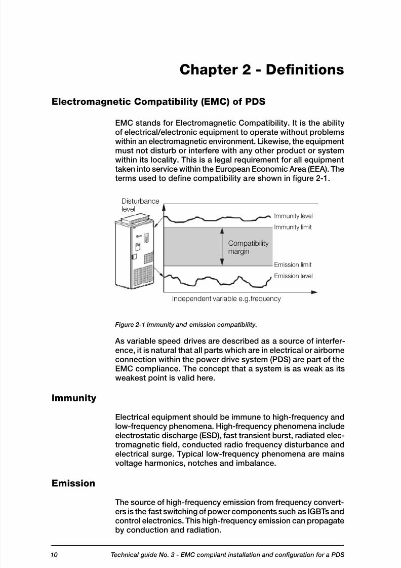
EMC stands for Electromagnetic Compatibility. It is the abilityof electrical/electronic equipment to operate without problemswithin an electromagnetic environment. Likewise, the equipmentmust not disturb or interfere with any other product or systemwithin its locality. This is a legal requirement for all equipmenttaken into service within the European Economic Area (EEA). Theterms used to define compatibility are shown in figure 2-1.
Figure 2-1 Immunity and emission compatibility.
As variable speed drives are described as a source of interfer-ence, it is natural that all parts which are in electrical or airborneconnection within the power drive system (PDS) are part of theEMC compliance. The concept that a system is as weak as itsweakest point is valid here.
Immunity
Electrical equipment should be immune to high-frequency andlow-frequency phenomena. High-frequency phenomena includeelectrostatic discharge (ESD), fast transient burst, radiated elec-tromagnetic field, conducted radio frequency disturbance andelectrical surge. Typical low-frequency phenomena are mainsvoltage harmonics, notches and imbalance.
Emission
The source of high-frequency emission from frequency convert-ers is the fast switching of power components such as IGBTs andcontrol electronics. This high-frequency emission can propagateby conduction and radiation.

8/6/2019 03 Technical Guide EMC Compliant Installation
http://slidepdf.com/reader/full/03-technical-guide-emc-compliant-installation 11/4411Technical guide No. 3 - EMC compliant installation and configuration for a PDS
Installation or part of installation
Power drive system PDS
Basic drive moduleBDM control, converterand protection
Feeding sectionauxiliaries and others
Motorand
sensors Drivenequipment
Complete drive module CDM
System control and
sequencing
Power drive system
The parts of a variable speed drive controlling driven equip-
ment as a part of an installation are described in EMC ProductStandard EN 61800-3. A drive can be considered as a BasicDrive Module (BDM) or Complete Drive Module (CDM) accord-ing to the standard.
It is recommended that personnel responsible for design andinstallation have this standard available and be familiar with thisstandard. All standards are available from the national stand-ardization bodies.
Systems made by an OEM or panel builder can consist more
or less of the PDS parts alone, or there can be many PDSs ina configuration.
The solutions described in this guide are used within the defini-tion of power drive system, but the same solutions can, or insome cases, should, be extended to all installations. This guidegives principles and practical EMC examples, which can be ap-plied to a user’s system.
Figure 2-2 Abbreviations used in drives.
Definitions

8/6/2019 03 Technical Guide EMC Compliant Installation
http://slidepdf.com/reader/full/03-technical-guide-emc-compliant-installation 12/4412 Technical guide No. 3 - EMC compliant installation and configuration for a PDS
Types of equipment
The EMC Directive (2004/108/EC) defines equipment as any
apparatus or fixed installation. As there are separate provi-sions for apparatus and fixed installations, it is important thatthe correct category of the equipment (PDM, CDM or BDM) isdetermined.
In technical-commercial classifications the following terminol-ogy is frequently used: components, sub-assemblies, finishedappliances (i.e. finished products), a combination of finishedappliances (i.e. a system), apparatus, fixed installations andequipment.
The key issue here is whether the item is meant for end usersor not:if it is meant for end users, the EMC directive applies;if it is meant for manufacturers or assemblers, the EMCdirective does not apply.
Components or sub-assemblies intended for incorporation
into an apparatus by the end users
A manufacturer may place components or sub-assemblies onthe market, which are:
for incorporation into an apparatus by the end-user,available to end-users and likely to be used by them.
These components or sub-assemblies are to be considered asapparatus with regard to the application of the EMC. The instruc-tions for use accompanying the component or sub-assemblyshould include all relevant information, and should assume thatadjustments or connections can be performed by an end usernot aware of the EMC implications.
In such case the component is considered equivalent to appa-ratus. Some variable speed power drive products fall into thiscategory, e.g. a drive with enclosure and sold as a complete unit(CDM) to the end user who installs it into his own system. Allprovisions of the EMC Directive will apply (CE mark, EC declara-tion of conformity and technical documentation).
Components or sub-assemblies intended for incorporation
into an apparatus by other manufacturers or assemblers
Components or sub-assemblies intended for incorporation into
an apparatus or another sub-assembly by other manufacturersor assemblers are not considered to be “apparatus” and aretherefore not covered by the EMC Directive. These componentsinclude resistors, cables, terminal blocks, etc.
••
••
Definitions

8/6/2019 03 Technical Guide EMC Compliant Installation
http://slidepdf.com/reader/full/03-technical-guide-emc-compliant-installation 13/4413Technical guide No. 3 - EMC compliant installation and configuration for a PDS
Some variable speed power drive products fall into this categoryas well, e.g. basic drive modules (BDM). These are meant to beassembled by a professional assembler (e.g. panel builder orsystem manufacturer) into a cabinet not in the scope of deliveryof the manufacturer of the BDM. According to the EMC Directive,the requirement for the BDM supplier is to provide instructionsfor installation and use.
Note:The manufacturer or assembler of the panel or system is re-sponsible for the CE mark, the EC Declaration of Conformity,and the technical documentation.
Finished appliance
A finished appliance is any device or unit containing electricaland/or electronic components or sub-assemblies that deliversa function and has its own enclosure. Similarly to components,the interpretation “finished appliance” can be divided into twocategories: it can be intended for end users, or for other manu-facturers or assemblers.
Finished appliance intended for end users
A finished appliance is considered as apparatus in the sense of
the EMC Directive if it is intended for the end-user and thus hasto fulfill all the applicable provisions of the Directive.
Variable speed power drive products that fall into this categoryare whole power drive systems (PDS) or complete drive mod-ules (CDM). In this case all provisions of the EMC Directive willapply (CE mark, EC Declaration of Conformity, and technicaldocumentation). The drive product manufacturer is responsiblefor the CE mark, EC Declaration of Conformity, and technicaldocumentation.
Finished appliance intended for other manufacturer or
assembler
When the finished appliance is intended exclusively for anindustrial assembly operation for incorporation into other ap-paratus, it is not an apparatus in the sense of the EMC Directiveand consequently the EMC Directive does not apply for suchfinished appliances.
The variable speed power drive products that fall into this
category are basic drive modules (BDM). The approach is thesame as for components or sub-assemblies when they are
Definitions

8/6/2019 03 Technical Guide EMC Compliant Installation
http://slidepdf.com/reader/full/03-technical-guide-emc-compliant-installation 14/4414 Technical guide No. 3 - EMC compliant installation and configuration for a PDS
intended for incorporation into an apparatus by another manu-facturer or assembler. Thus the manufacturer or assembler ofthe panel or system is responsible for all actions relating tothe EMC Directive.
Systems (combination of finished appliances)
A combination of several finished appliances which is combined,and/or designed and/or put together by the same party (i.e.the system manufacturer) and is intended to be placed on themarket for distribution as a single functional unit for an end-userand intended to be installed and operated together to performa specific task.
All provisions of the EMC Directive, as defined for apparatus,apply to the combination as a whole. The variable speed powerdrive products that fall into this category are power drive sys-tems (PDS). Thus the manufacturer of the PDS is responsiblefor all actions relating to the EMC Directive.
Apparatus
Apparatus means any finished appliance or combination thereofmade commercially available (i.e. placed on the market) as asingle functional unit, intended for the end-user, and liable to
generate electromagnetic disturbance, or the performance ofwhich is liable to be affected by such disturbance.
Fixed installation
A particular combination of several types of apparatus, equip-ment and/or components, which are assembled, installed andintended to be used permanently at a predefined location.
Equipment
Any apparatus or fixed installation
CE marking for EMC
Components or sub-assemblies intended for incorporation intoan apparatus by the end users need to carry the CE markingfor EMC.
Components or sub-assemblies intended for incorporation intoan apparatus by another manufacturer or assembler do not needto carry the CE marking for EMC.Note: The products may carry the CE marking for other direc-tives than EMC.
Definitions
8/6/2019 03 Technical Guide EMC Compliant Installation
http://slidepdf.com/reader/full/03-technical-guide-emc-compliant-installation 15/4415Technical guide No. 3 - EMC compliant installation and configuration for a PDS
Medium voltage network
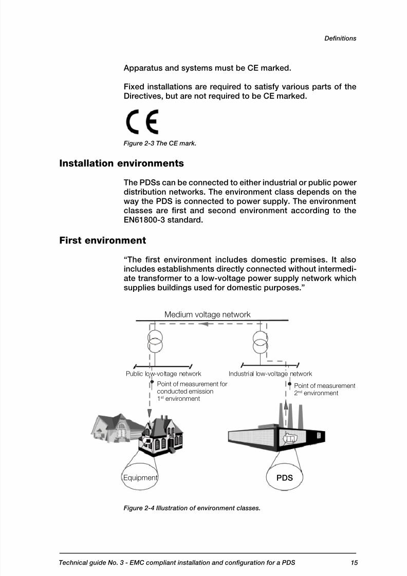
Point of measurement forconducted emission1st environment
Equipment PDS
Public low-voltage network Industrial low-voltage network
Point of measurement2nd environment
Apparatus and systems must be CE marked.
Fixed installations are required to satisfy various parts of theDirectives, but are not required to be CE marked.
Figure 2-3 The CE mark.
Installation environments
The PDSs can be connected to either industrial or public powerdistribution networks. The environment class depends on the
way the PDS is connected to power supply. The environmentclasses are first and second environment according to theEN61800-3 standard.
First environment
“The first environment includes domestic premises. It alsoincludes establishments directly connected without intermedi-ate transformer to a low-voltage power supply network whichsupplies buildings used for domestic purposes.”
Figure 2-4 Illustration of environment classes.
Definitions

8/6/2019 03 Technical Guide EMC Compliant Installation
http://slidepdf.com/reader/full/03-technical-guide-emc-compliant-installation 16/4416 Technical guide No. 3 - EMC compliant installation and configuration for a PDS
Second environment
“The second environment includes all establishments other than
those directly connected to a low-voltage power supply networkwhich supplies buildings used for domestic purposes”.
EMC emission limits
The product standard EN 61800-3 divides PDSs into four cat-egories according to the intended use. In Europe, the standardtakes precedence over all generic or product family EMC stand-ards previously applicable. Limits for certain conditions can beselected by using the flow chart shown in figure 2-5.
PDS of category C1
A PDS (or CDM) with rated voltage less than 1000 V and intended
for use in the first environment. A PDS (or CDM) sold “as built” to
the end user.
The PDS manufacturer is responsible for the EMC behavior ofthe PDS under specified conditions. Additional EMC measuresare described in an easy-to-understand way and can be imple-mented by a layman.
When PDS/CDM is to be incorporated with another product, theresulting EMC behavior of that product is the responsibility of theassembler of the final product, by following the manufacturer’srecommendations and guidelines.
PDS of category C2
A PDS (or CDM/BDM) with rated voltage less than 1,000 V, which is
neither a plug in device nor a movable device and is intended to be
installed and commissioned only by a professional. A PDS (or CDM/
BDM) sold to be incorporated into an apparatus, system or installation.
When a PDS/CDM/BDM is to be incorporated with anotherproduct, the resulting EMC behavior of that product is the re-sponsibility of the assembler of the final product.
PDS of category C3
A PDS (or CDM/BDM) with rated voltage less than 1,000 V, intended
for use in the second environment. A PDS (or CDM/BDM) sold
“as built” to the end user or in order to be incorporated into an
apparatus, system or installation.
Definitions

8/6/2019 03 Technical Guide EMC Compliant Installation
http://slidepdf.com/reader/full/03-technical-guide-emc-compliant-installation 17/4417 Technical guide No. 3 - EMC compliant installation and configuration for a PDS
The PDS manufacturer is responsible for the EMC behavior ofthe PDS under specified conditions. Additional EMC measuresare described in an easy-to-understand way and can be imple-mented by a layman.
When a PDS/CDM is to be incorporated with another product,the resulting EMC behavior of that product is the responsibilityof the assembler of the final product, by following the manufac-turer’s recommendations and guidelines.
PDS of category C4
A PDS (or CDM/BDM) with rated voltage equal to or above 1,000 V, or
rated current equal to or above 400 A, or intended for use in complex
systems in the second environment. A PDS (or CDM/BDM) sold to be
incorporated into an apparatus, system or installation.
Category C4 requirements include all other EMC requirementsexcept for radio frequency emission. They are assessed onlywhen it is installed in its intended location. Therefore a categoryC4 PDS is treated as a fixed installation, and thus has no require-ment for an EC Declaration of Conformity or CE Marking.
The EMC directive requires the accompanying documentation to
identify the fixed installation, its electromagnetic compatibilitycharacteristics and the person responsible, and to indicate theprecautions to be taken in order not to compromise the con-formity of that installation.
In order to comply with the above requirements in the case of acategory C4 PDS (or CDM/BDM), the user and the manufacturershall agree on an EMC plan to meet the EMC requirements forthe intended application. In this situation, the user defines theEMC characteristics of the environment including the wholeinstallation and the neighborhood. The PDS manufacturer shall
provide information on typical emission levels and installationguidelines for the PDS to be installed. The resulting EMC be-havior is the responsibility of the installer (e.g. by following theEMC plan).
Where there are indications of non-compliance of the categoryC4 PDS after commissioning, the standard includes a procedurefor measuring the emission limits outside the boundary of aninstallation.
Definitions

8/6/2019 03 Technical Guide EMC Compliant Installation
http://slidepdf.com/reader/full/03-technical-guide-emc-compliant-installation 18/4418 Technical guide No. 3 - EMC compliant installation and configuration for a PDS
EN 61800-3EMC product standard for PDS
1st environment(public low-voltage network)
2nd environment(industrial network)
EMC plan
CONDUCTED
R ADI
ATED
Disturbance
Figure 2-5 Emission limits for PDS.
Definitions

8/6/2019 03 Technical Guide EMC Compliant Installation
http://slidepdf.com/reader/full/03-technical-guide-emc-compliant-installation 19/4419Technical guide No. 3 - EMC compliant installation and configuration for a PDS
Radiated emission
Supply
network
Conducted
emission
Earth
Control
Process
Motor
connectionMotor
Chapter 3 - EMC solutions
General
The solutions used to fulfill immunity and both radiated and con-ducted emission requirements are described in this chapter.
Solutions for EMC compatibility
There are some basic principles which must be followed whendesigning and using drive systems incorporating AC drive prod-ucts. These same principles were used when these products
were initially designed and constructed, where such issues asprinted circuit board layout, mechanical design, wire routing,cable entries and other special points were all considered ingreat detail.
Emissions
The emissions can be classified into two types; conducted emis-sion and radiated emission. The disturbances can be emitted invarious ways as shown in the following figure:
Figure 3-1 Emissions.
Conducted emission
Conducted disturbances can propagate to other equipment viaall conductive parts including cabling, earthing and the metal
frame of an enclosure.

8/6/2019 03 Technical Guide EMC Compliant Installation
http://slidepdf.com/reader/full/03-technical-guide-emc-compliant-installation 20/44 20 Technical guide No. 3 - EMC compliant installation and configuration for a PDS
Conductive emissions can be reduced in the following way:
By RFI filtering for HF disturbancesUsing ferrite rings in power connection pointsUsing an AC or DC choke (even meant against harmonics,it reduce HF disturbances as well.Using an LCL filter in the case of regenerative drivesUsing a du/dt filter
Radiated emission
To be able to effectively prevent disturbance through the air, allparts of the power drive system should form a Faraday cageagainst radiated emissions. The installation of a PDS includes
cabinets, auxiliary boxes, cabling, motors, etc.
Some methods for ensuring the continuity of the Faraday cageare listed as follows:
Enclosure
The enclosure must have an unpainted non-corrodingsurface finish at every point where other plates, doors,etc. make contact.Unpainted metal-to-metal contacts shall be used through-
out, with conductive gaskets, where appropriate.Use unpainted installation plates, bonded to a commonearth point, ensuring all separate metal items are firmlybonded to achieve a single path to earth.Use conductive gaskets in doors and covers. Separatethe radiative i.e. “dirty” side from the “clean side” bymetal covers and design.Holes in enclosure should be minimized.
Cabling & wiring
Use special HF cable entries for high frequency earthingof power cable shields.Use conductive gaskets for HF earthing of control cableshield.Use shielded power and control cables. See productspecific manuals. Allow no breaks in the cable shields.Select low impedance shield connections on the MHzrange.Route power and control cables separately.
Use twisted pairs to avoid disturbances.Use ferrite rings for disturbances, if necessary.Select and route internal wires correctly.See product specific manuals
•••
••
•
•
•
•
•
•
•
•
••
•
••••
EMC solutions

8/6/2019 03 Technical Guide EMC Compliant Installation
http://slidepdf.com/reader/full/03-technical-guide-emc-compliant-installation 21/44 21Technical guide No. 3 - EMC compliant installation and configuration for a PDS
Rectifier
RFI
filter
Dirty side
Clean side
Installation
Auxiliaries used with complete drive modules (CDMs) shouldbe CE marked products conforming to both the EMC & Low Voltage Directives, NOT ONLY to the LV directive, unless theyare intended for incorporation into an apparatus by anothermanufacturer or assembler.Selection and installation of accessories in accordance withmanufacturers’ instructions.For wall-mounted units, strip the sheathing of a motor cableback far enough to expose the copper wire screen so thatthe screen can be twisted into a pigtail. Keep the short pigtailshort and connect it to the ground.For cabinet –models, lead the cables into the inside of the
enclosure. Apply 360° grounding of the cable shield at theentry into the cabinet. See product specific manuals.360° earthing at motor end. See motor manuals.
Clean and dirty side
The circuit before the point where the supply power is connectedto the CDM and where the filtering starts is referred to as theclean side. The parts of the BDM that can cause disturbancesare described as the dirty side.
Enclosed wall-mounted drives are designed so that the circuitfollowed by the output connection is the only dirty part. That isthe case if the installation instructions of the drive are followed.
To be able to keep the clean side “clean”, the dirty parts areseparated into a Faraday cage. This can be done either withseparation plates or with cabling.
Figure 3-2 “Clean” and “dirty” sides of the BDM
•
•
•
•
•
EMC solutions

8/6/2019 03 Technical Guide EMC Compliant Installation
http://slidepdf.com/reader/full/03-technical-guide-emc-compliant-installation 22/44 22 Technical guide No. 3 - EMC compliant installation and configuration for a PDS
Line Line
When using separation plates, the rules for enclosure holes areapplicable (see Holes in enclosures section later in this chapter).
When the Faraday cage is formed by cabling, the rules forcabling must be applied (see sections on cabling and wiringin this chapter and follow the product specific instructions forthe drive).
The use of additional components, e.g. contactors, isolators,fuses, etc. in some cases makes it difficult to keep the cleanand the dirty side separate.
This can happen when contactors or switches are used in cir-cuits to change over from clean to dirty side (e.g. by-pass).
Some examples of solutions are described in chapter 4, Practi-cal examples.
RFI filtering
RFI filters are used to attenuate conducted disturbances in aline connecting point where the filter leads the disturbances toearth.
Output filters attenuate disturbances at the output of a PDS.
E.g. du/dt and common mode filters help somewhat, even ifthey have not been designed for RFI.
Filters cannot be used in a floating network (IT-network) wherethere is high impedance or no physical connection between thephases and the earth.
Figure 3-3 Example of filtering integrated in drive module.
Figure 3-3 shows an example of integral, distributed filtering.
Some drive products need a separate filter (see product specificinstructions).
EMC solutions

8/6/2019 03 Technical Guide EMC Compliant Installation
http://slidepdf.com/reader/full/03-technical-guide-emc-compliant-installation 23/44 23Technical guide No. 3 - EMC compliant installation and configuration for a PDS
EMC solutions
Selecting the RFI filter
An RFI filter is selected to attenuate the conducted disturbances.
It is not possible to compare the disturbances measured froma source, and the insertion loss for a filter, as the measurementbase for the two items of information will not correspond.
It is always necessary to test a filter in conjunction with thesource of disturbance to ensure adequate attenuation and tomeet applicable emission limits.
Installation of the RFI filter
Reliable HF/low impedance connections are essential to ensure
proper functioning of the filter, therefore the following instruc-tions are to be followed.
The filter shall be assembled on a metal plate with un-painted connection points all in accordance with the filtermanufacturer’s instructions.The orientation of the filter must be such that it providesenough distance between the input and output wiring ofthe filter in order to prevent cross-coupling between theclean and dirty side.The length of the cable between the filter and the drivemust be minimized.
The input cable of the filter shall be separated from thecable which connects the filter to the driveThe input cable of the filter shall be separated from themotor cable
Selection of a secondary enclosure
Where the BDM is to be installed, (e.g. an IP00 open chassisconverter), or if additional components are to be connected tothe dirty side of an otherwise compliant unit, it is always neces-
sary to provide an EMC enclosure.
For enclosed chassis modules where the motor connectionsare made directly to the converter output terminals and all theinternal shielding parts are fitted, there are no requirements forspecial enclosures.
If drives are fitted with output switching devices, for example,then an EMC enclosure will be needed, as the integral Faradaycage will no longer apply.
As a reminder, EMC is only one part of enclosure selection. Theenclosure is sized according to several criteria:
SafetyDegree of protection (IP rating)
•
•
•
•
•
••
8/6/2019 03 Technical Guide EMC Compliant Installation
http://slidepdf.com/reader/full/03-technical-guide-emc-compliant-installation 24/44 24 Technical guide No. 3 - EMC compliant installation and configuration for a PDS
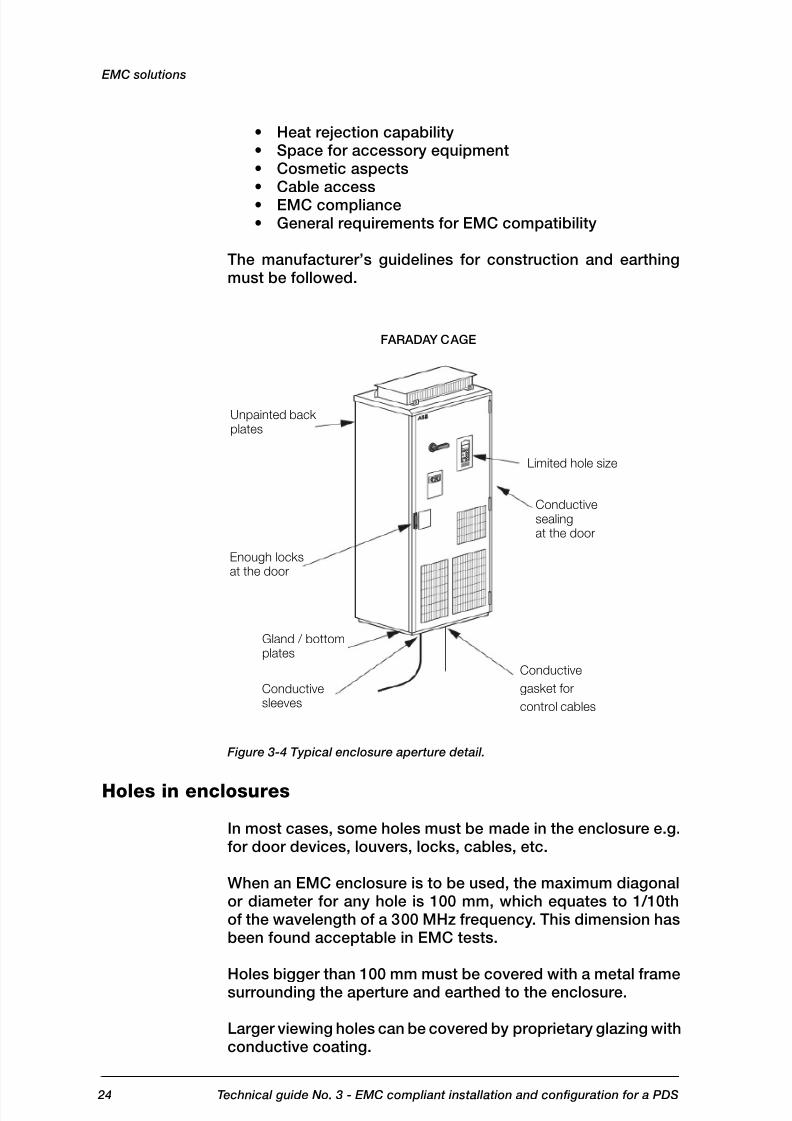
FARADAY CAGE
Unpainted backplates
Enough locksat the door
Gland / bottomplates
Conductivesleeves
Limited hole size
Conductivesealingat the door
Conductive
gasket for
control cables
Heat rejection capabilitySpace for accessory equipmentCosmetic aspectsCable accessEMC complianceGeneral requirements for EMC compatibility
The manufacturer’s guidelines for construction and earthingmust be followed.
Figure 3-4 Typical enclosure aperture detail.
Holes in enclosures
In most cases, some holes must be made in the enclosure e.g.for door devices, louvers, locks, cables, etc.
When an EMC enclosure is to be used, the maximum diagonalor diameter for any hole is 100 mm, which equates to 1/10thof the wavelength of a 300 MHz frequency. This dimension hasbeen found acceptable in EMC tests.
Holes bigger than 100 mm must be covered with a metal framesurrounding the aperture and earthed to the enclosure.
Larger viewing holes can be covered by proprietary glazing withconductive coating.
••••••
EMC solutions

8/6/2019 03 Technical Guide EMC Compliant Installation
http://slidepdf.com/reader/full/03-technical-guide-emc-compliant-installation 25/44 25Technical guide No. 3 - EMC compliant installation and configuration for a PDS
Maximum size 72x72 mminstrument
Twisted pair
<100 mm
Install locks to
unpainted door
Check that there is no holes >100 mm
Metal cover for
holes >100 mm
Glazing must be connected to non-painted metal surrounds withconductive double-sided tape or conductive gasket.
Figure 3-5 Essential points of power connections.
360° HF earthing
360° HF earthing should be done everywhere where cables enterthe drive enclosure, auxiliary connection box or motor. Thereare different ways to implement the HF earthing. The solutionsused in ABB’s CDM/BDM products are described here.
HF earthing with cable glands
The cable glands, which are specially designed for 360° HF
earthing, are suitable for power cables with a diameter lessthan 50 mm.
Cable glands are not normally used for control cables due tothe fact that the distance from the control connections to thecable glands is often too long for reliable HF earthing. If theglands are used with control cables, the cable shielding mustcontinue as near to the control connections as possible. Onlythe outer insulation of cable should be removed to expose thecable screen for the length of the cable gland.
To get the best possible result from HF earthing, the cable shield-ing should be covered with a conductive tape. The tape mustcover the whole surface of the shielding, including pigtail, andshould be tightly pressed with fingers after every single turn.
EMC solutions

8/6/2019 03 Technical Guide EMC Compliant Installation
http://slidepdf.com/reader/full/03-technical-guide-emc-compliant-installation 26/44 26 Technical guide No. 3 - EMC compliant installation and configuration for a PDS
SUPPLY CABLE MOTOR CABLE
As short unshielded
wires as possible
Cable shielding
covered with
conductive tape
EMC cable
gland
Clamping nut
CableContinuity of
faraday cage
Short pigtail
Unpainted gland plate
Conductive shielding &
compression seal
Short pigtail
Note conductive tape on the cable shielding
Conductivesleeve
Cable
Continuity of
faraday cage
Unpainted gland
plate with collars
Unpainted bottom plate
Figure 3-6 Essential points of power connections.
HF earthing with conductive sleeve
360° HF earthing in power cable entries can be done by usinga conductive sleeve around the cable shielding. The sleeve is
connected to the Faraday cage by tightening it to the speciallydesigned collar in the gland plate.
Figure 3-7 360° earthing with conductive sleeve.
EMC solutions

8/6/2019 03 Technical Guide EMC Compliant Installation
http://slidepdf.com/reader/full/03-technical-guide-emc-compliant-installation 27/44 27 Technical guide No. 3 - EMC compliant installation and configuration for a PDS
Above cable clamp,cover bare shield withinsulating tape
Cable clamp on bare shield
Motor cable Braking resistor cable
0.5...0.6 Nm (4.4...5.3 lbf in)
1.5 Nm (13 lbf in)
1.5 Nm (13 lbf in)
Figure 3-8 360° earthing with clamping of cable shield
The advantage of this solution is that the same sleeve can beused for cables with different diameters.
The cable can be mechanically supported by clamps, and aspecific cable gland is not required.
Note that the sleeve does not act as a strain relief clamp.
360° earthing at motor end
The continuity of the Faraday cage at the motor end must beensured by the same methods as in cabinet entry, namely:
Faraday cage and IP55 degree of protection. This includes:Cable gland providing galvanic contact must be used forclamping the cable.Cable shielding should be sealed with conductive tape.Conductive gaskets should be used for sealing both thecable gland plate and the terminal box cover
Note: Please check availability from motor manufacturer. Itis common that this is one option for the motorPigtails of earthing conductors must be as short as pos-sible.
••
••
•
•
EMC solutions
8/6/2019 03 Technical Guide EMC Compliant Installation
http://slidepdf.com/reader/full/03-technical-guide-emc-compliant-installation 28/44 28 Technical guide No. 3 - EMC compliant installation and configuration for a PDS
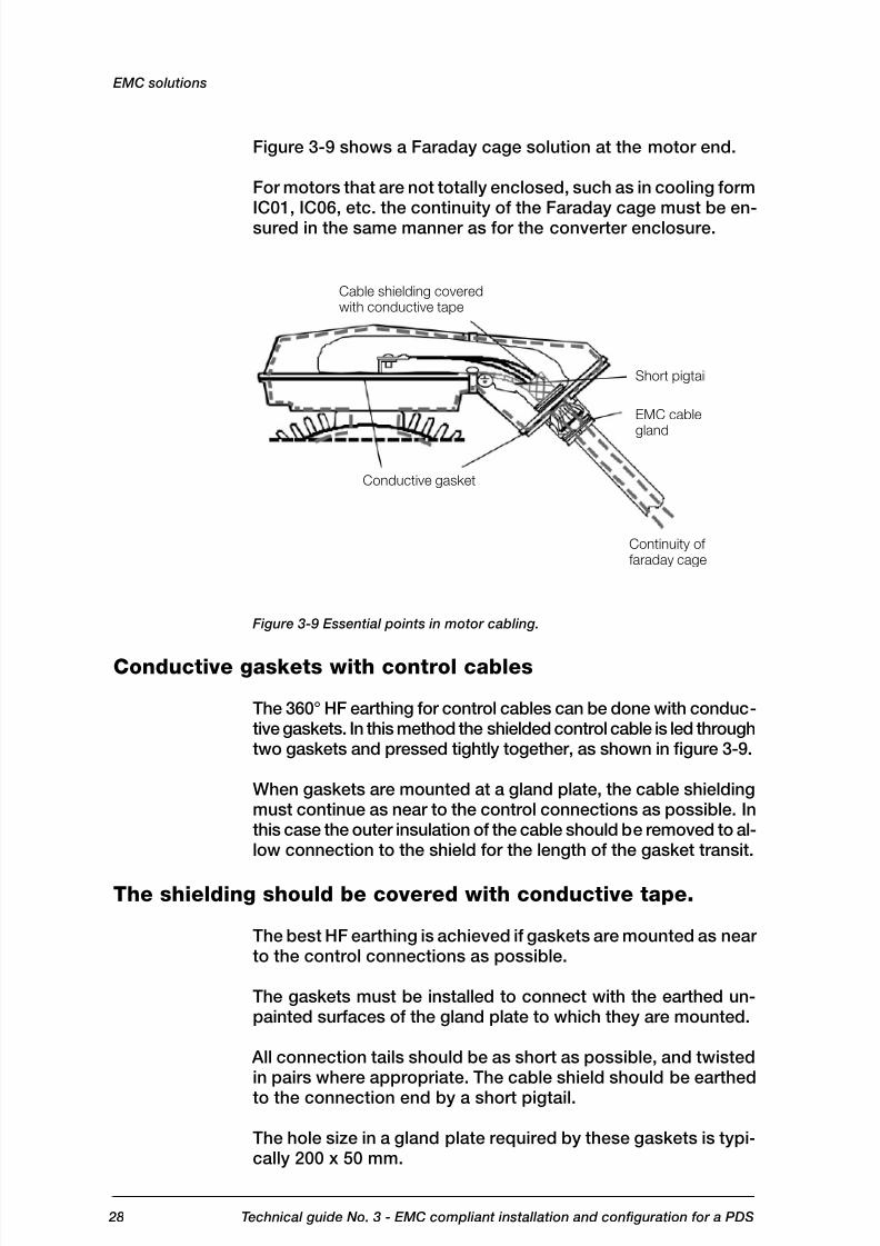
Cable shielding coveredwith conductive tape
Short pigtail
EMC cable
gland
Continuity of faraday cage
Conductive gasket
Figure 3-9 shows a Faraday cage solution at the motor end.
For motors that are not totally enclosed, such as in cooling formIC01, IC06, etc. the continuity of the Faraday cage must be en-sured in the same manner as for the converter enclosure.
Figure 3-9 Essential points in motor cabling.
Conductive gaskets with control cables
The 360° HF earthing for control cables can be done with conduc-tive gaskets. In this method the shielded control cable is led throughtwo gaskets and pressed tightly together, as shown in figure 3-9.
When gaskets are mounted at a gland plate, the cable shieldingmust continue as near to the control connections as possible. Inthis case the outer insulation of the cable should be removed to al-low connection to the shield for the length of the gasket transit.
The shielding should be covered with conductive tape.
The best HF earthing is achieved if gaskets are mounted as nearto the control connections as possible.
The gaskets must be installed to connect with the earthed un-painted surfaces of the gland plate to which they are mounted.
All connection tails should be as short as possible, and twistedin pairs where appropriate. The cable shield should be earthed
to the connection end by a short pigtail.
The hole size in a gland plate required by these gaskets is typi-cally 200 x 50 mm.
EMC solutions

8/6/2019 03 Technical Guide EMC Compliant Installation
http://slidepdf.com/reader/full/03-technical-guide-emc-compliant-installation 29/44 29Technical guide No. 3 - EMC compliant installation and configuration for a PDS
As short as possible
S h i e l d Control
connections
Wrap copper tabe around the stripped partof the cable under the clamp. Be careful.Do not cut the grounding wire. Clamp asclose to the terminals as possible.
Figure 3-10 Essential points for control cabling transit.
Installation of accessories
The variety of accessories that can be installed is so large thatonly basic principles for selection and installation can be givenfor them.
Accessories can, however, be divided into two categoriesdepending on how immune/sensitive they are. The protecteddevice in this context means its ability to keep the Faraday cageclosed. It is therefore recommended to use metal enclosed/ shielded devices wherever such devices are available.
The rules for holes in the enclosure must be applied if there aredevices forming a bridge between the clean side and the dirtyside, which can be disturbed.
Typical open devices are fuses, switch fuses, contactors etc.,which do not have a metal covering around them.
In general, such devices cannot be installed into the clean sidewithout protective metallic shielding plates. The rules for holesin the enclosure must then be applied.
Some examples of protected and open devices are given in thechapter Practical examples.
Internal wiring
There are some basic rules for internal wiring: Always keep clean and dirty side cables separate and
shielded from one another.Internal clean power connections with integrally filtereddrive units, e.g. from contactor to converter input, do notrequire shielded cables but may require de-coupling fer-rite rings where they enter the converter input.
•
•
EMC solutions

8/6/2019 03 Technical Guide EMC Compliant Installation
http://slidepdf.com/reader/full/03-technical-guide-emc-compliant-installation 30/44 30 Technical guide No. 3 - EMC compliant installation and configuration for a PDS
CABINETDEVICE
Analogue
Signal (V)
AnalogueSignal (mA)
POTENTIAL FREEDIG. OUTPUT
DO
DO
DOOR DEVICE Twist these
pairs of pairs
Use shielded cables for Analogue mA signals
For earthing rules see part Control Cabing
Don’t mix differentsignal levels
Diode for DC relay
Don’t mix different signal levels
RC filter orvaristor for AC relay
CLEAN SIDE
DIRTY SIDE
Avoid parallel running with control wires
Cross in 90°
Keep these separate (see figure 3-11)
Avoid parallel running with control wiresCross in 90° angle
SUPPLYCONNECTION
MOTOROUTPUT
Twist the pairsup to terminals
GNDNC
Common
NO
NC
Common
NO
NC
Common
NO
RELAY OUTPUTS(pot. free)
ANALOGUE SIGNALS
DIGITAL INPUTS
GND
Use twisted pair wires wherever possible.Use shielded twisted pairs for signal level outward andreturn wires exiting from the overall enclosure. Avoid mixing pairs with different signal types e.g.110 VAC, 230 VAC, 24 VDC, analogue, digital.Run wires along the metal surface and avoid wires hang-ing in free air, which can become an antenna.If plastic trunking is used, secure it directly to installationplates or the framework. Do not allow spans over free air,which could form an antenna.Keep power and control wiring separate.Use galvanically isolated (potential free) signals.Keep wires twisted as near the terminal as possible.Keep pigtails as short as possible.
Earthing connections should be as short as possible inflat strip, multi-stranded or braided flexible conductorsfor low RFI impedance.
Figure 3-11 Principles of wiring inside CDM.
••
•••
•
••••
•
EMC solutions

8/6/2019 03 Technical Guide EMC Compliant Installation
http://slidepdf.com/reader/full/03-technical-guide-emc-compliant-installation 31/44 31Technical guide No. 3 - EMC compliant installation and configuration for a PDS
Product specific manual
Motor cable
Mains cable
Signal / control cables
Control cables and cabling
The control cabling is a part of the Faraday cage as described
in the section Conductive gaskets with control cables.
In addition to correct HF earthing there are some basic rulesfor control cabling:
Always use shielded twisted pair cables:double-shielded cable for analogue signalssingle-shielded for other signals is acceptable, butdouble-shielded cable is recommended.
Don’t run 110/230 V signals in the same cable as lower signallevel cables.
Keep twisted pairs individual for each signal.Earth directly on the frequency converter side.
If instructions for the device at the other end of the cable specifyearthing at that end, earth the inner shields at the end of the moresensitive device and the outer shield at the other end.
Route signal cables according to figure 3-12 whenever possible, andfollow instructions given by the product specific manuals.
Figure 3-12 Routing principles of control cables.
There is more about control cabling in the “Grounding and cabling
of the drive system” documents” and in product specific manuals.
•••
•
••
EMC solutions
8/6/2019 03 Technical Guide EMC Compliant Installation
http://slidepdf.com/reader/full/03-technical-guide-emc-compliant-installation 32/44 32 Technical guide No. 3 - EMC compliant installation and configuration for a PDS
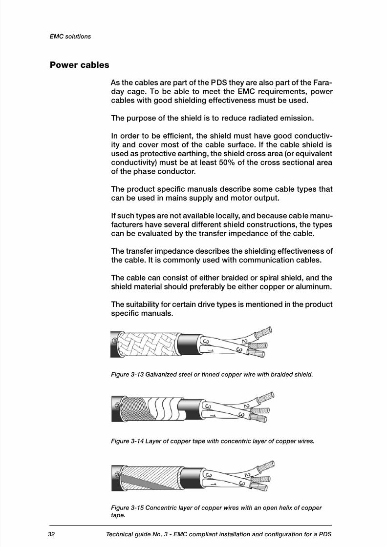
Power cables
As the cables are part of the PDS they are also part of the Fara-day cage. To be able to meet the EMC requirements, powercables with good shielding effectiveness must be used.
The purpose of the shield is to reduce radiated emission.
In order to be efficient, the shield must have good conductiv-ity and cover most of the cable surface. If the cable shield isused as protective earthing, the shield cross area (or equivalentconductivity) must be at least 50% of the cross sectional areaof the phase conductor.
The product specific manuals describe some cable types thatcan be used in mains supply and motor output.
If such types are not available locally, and because cable manu-facturers have several different shield constructions, the typescan be evaluated by the transfer impedance of the cable.
The transfer impedance describes the shielding effectiveness ofthe cable. It is commonly used with communication cables.
The cable can consist of either braided or spiral shield, and the
shield material should preferably be either copper or aluminum.
The suitability for certain drive types is mentioned in the productspecific manuals.
Figure 3-13 Galvanized steel or tinned copper wire with braided shield.
Figure 3-14 Layer of copper tape with concentric layer of copper wires.
Figure 3-15 Concentric layer of copper wires with an open helix of copper
tape.
EMC solutions

8/6/2019 03 Technical Guide EMC Compliant Installation
http://slidepdf.com/reader/full/03-technical-guide-emc-compliant-installation 33/44 33Technical guide No. 3 - EMC compliant installation and configuration for a PDS
Transferimpedance(mOhm/m)
Non-recommended cable
Galvanised steel or tinnedcopper wire with braided shield(fig. 3-12)
Layer of copper tabe withconcentric layer of copper wires(fig. 3.13)
Corrugated shield
Frequency (MHz)
EMC solutions
Transfer impedance
To meet the requirements for radiated emission, the transfer
impedance must be less than 100 mΩ
/m in the frequency rangeup to 100 MHz. The highest shielding effectiveness is achievedwith a metal conduit or corrugated aluminum shield. Figure3-16 shows typical transfer impedance values of different cableconstructions. The longer the cable run, the lower the transferimpedance required.
Figure 3-16 Transfer impedance for power cables.
Use of ferrite rings
In particular cases, due to high emission levels, common modeinductors can be used in signal cables to avoid interfacingproblems between different systems.
Common mode disturbances can be suppressed by wiringconductors through the common mode inductor ferrite core(figure 3-17).
The ferrite core increases inductance of conductors and mutualinductance, so common mode disturbance signals above a cer-tain frequency are suppressed. An ideal common mode inductordoes not suppress a differential mode signal.

8/6/2019 03 Technical Guide EMC Compliant Installation
http://slidepdf.com/reader/full/03-technical-guide-emc-compliant-installation 34/44 34 Technical guide No. 3 - EMC compliant installation and configuration for a PDS
EMC solutions
Figure 3-17 Ferrite ring in signal wire.
The inductance (i.e. the ability to suppress HF disturbances) canbe increased by multiple turns of the signal wire.
When using a ferrite ring with power cable, all phase conductors
should be led through the ring. The shielding and possible earthwire must be wired outside the ring to keep the common modeinductor effect. With power cables it is not normally possibleto make multiple turns through the ring. The inductance can beincreased by using several successive rings.
If for any reasons the installation instructions cannot be followedand therefore additional ferrites or filters are added afterwards,it is recommended that measurements be made to show con-formance.
8/6/2019 03 Technical Guide EMC Compliant Installation
http://slidepdf.com/reader/full/03-technical-guide-emc-compliant-installation 35/44 35Technical guide No. 3 - EMC compliant installation and configuration for a PDS
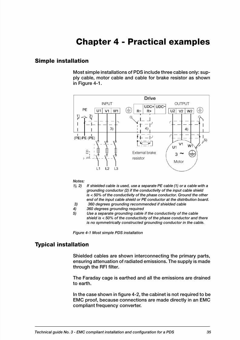
DriveINPUT OUTPUT
External brake
resistorMotor
Chapter 4 - Practical examples
Simple installation
Most simple installations of PDS include three cables only: sup-ply cable, motor cable and cable for brake resistor as shownin Figure 4-1.
Notes:
1), 2) If shielded cable is used, use a separate PE cable (1) or a cable with a
grounding conductor (2) if the conductivity of the input cable shield
is < 50% of the conductivity of the phase conductor. Ground the other
end of the input cable shield or PE conductor at the distribution board.
3) 360 degrees grounding recommended if shielded cable
4) 360 degrees grounding required
5) Use a separate grounding cable if the conductivity of the cable
shield is < 50% of the conductivity of the phase conductor and there
is no symmetrically constructed grounding conductor in the cable.
Figure 4-1 Most simple PDS installation
Typical installation
Shielded cables are shown interconnecting the primary parts,ensuring attenuation of radiated emissions. The supply is madethrough the RFI filter.
The Faraday cage is earthed and all the emissions are drainedto earth.
In the case shown in figure 4-2, the cabinet is not required to be
EMC proof, because connections are made directly in an EMCcompliant frequency converter.

8/6/2019 03 Technical Guide EMC Compliant Installation
http://slidepdf.com/reader/full/03-technical-guide-emc-compliant-installation 36/44 36 Technical guide No. 3 - EMC compliant installation and configuration for a PDS
Transformer
360° HF earthing
Shielded cable
Metalframecabinet
CabinetUnpainted
mounting
plate
Drive
RFI
FILTER
Metal box
Metal box
Rectifier
BRAKERESISTOR
BRAKECHOPPER
For connection details, seeProduct Specific Manualfor chopper and resistor.
For more details, see sectionon 360° EARTHING ATMOTOR END
CONTROL
1) Short pigtail
to PE, both common
and pair screen
2) 360° HF grounding
3) For rules, see part
CONTROL
CABLING
Motoroutput
Figure 4-2 Typical PDS configuration.
Example of by-pass system <100 kVA
In this case it is difficult to ensure that no cross coupling oc-curs between the dirty side of the converter and the clean sideabove the Direct On Line (DOL) contactor. Contactors are notRFI barriers, and the coil circuits are also vulnerable.
A suitable RFI filter at the supply input connections would re-quire to be able to pass the DOL starting current, which can besix to seven times the normal full load current, and would begreatly oversized for normal running, which makes it difficult todesign. Ferrite cores used in the feeds to the contactor will help
attenuate the coupled noise as shown in figure 4-3.
Practical examples

8/6/2019 03 Technical Guide EMC Compliant Installation
http://slidepdf.com/reader/full/03-technical-guide-emc-compliant-installation 37/44 37 Technical guide No. 3 - EMC compliant installation and configuration for a PDS
Transformer 360° HF earthing
Shielded cable
RADIATIVE i.e. DIRTY side
Cabinet 1
supply
connection
The ferrite in the DOL circuit isfor cross coupling of clean anddirty side Motor Output of PDS
Ferrite
Metal box
BY-PASS
CONTROL
CONTROL
RELAYS
OR PLC
Contactor
Motor
output
Metal box
Safety sw.
For more details, see360° MOTOR EARTHING
1) Short pigtail
tp PE, both common
and pair shield
3) For rules, see part
CONTROL
CABLING
Isolator
Isolator
RFI
FILTER
Contactor
Control
Metal boxDRIVE
MODULE
Metalframecabinet
Practical examples
Figure 4-3 Basic scheme with by-pass.
Typical example of 12-pulse drive
In this case a 12-pulse rectifier is an IT system, unearthed dueto the delta winding; therefore any filter in the line must be atthe primary side of the phase shift transformer.
Experience has shown that, in this case, with short connec-tions to the busbars, the earth shield between the transformerwindings is not quite adequate for conducted emissions at-
tenuation for use in the first environment. Therefore an RFI filtermay be needed at the primary side of the transformer for EMCcompliance. An RFI filter is not normally needed for the secondenvironment.

8/6/2019 03 Technical Guide EMC Compliant Installation
http://slidepdf.com/reader/full/03-technical-guide-emc-compliant-installation 38/44 38 Technical guide No. 3 - EMC compliant installation and configuration for a PDS
360° HF grounding
Shielded cable
Shielded control cables
Control & display
Enclosure, with segregation
Low voltage supply
Point of
measurement
Shielded motorcables
RFIFILTER
Commonearth
DRAIN FOR EMISSIONS
Incoming switch
fuse contactor
Phase shift
transformer(if integrated)
Rectifiers Inverter Output choke
(Ferrite)
Commonearth
DRAIN FOR EMISSIONS
Incoming switchfuse contactor
Phase shifttransformer(if integrated)
Rectifiers Inverter Output choke(Ferrite)
360° HF grounding
Shielded cable
Shielded control cables
Control & display Shielded motorcables
Enclosure,with segregation
Point of measurement
Medium or high voltage supply
For equipment fed from an IT system, a similar procedure canbe used. An isolating transformer allows the PDS to be earthedand to use a suitable filter, for use in the first environment. Thepoint of coupling is at a medium voltage and emissions maybe considered at the next low voltage point of coupling in thesystem. The level of emissions should correspond to those forthe appropriate environment. For definitions, see the Installationenvironments section in chapter 2.
Note: All equipment inside must be enclosed
Figure 4-4 12-pulse converter system fed at LV.
Figure 4-5 12-pulse converter system fed at LV (CDM, transformer and switch
fuse have separate housing).
Practical examples

8/6/2019 03 Technical Guide EMC Compliant Installation
http://slidepdf.com/reader/full/03-technical-guide-emc-compliant-installation 39/44 39Technical guide No. 3 - EMC compliant installation and configuration for a PDS
Practical examples
Example of EMC plan
This is a form for making an EMC plan where the user and the
manufacturer analyze the installation and define the measuresto be taken to achieve electromagnetic compatibility. The plandefines the responsibilities of the manufacturer, the installer andthe user of the drive. All these parties establish the plan jointly.Fill in and answer the questions below.
Step 1: Name the parties
Manufacturer/supplier ABB Oy, Drives
End user ABC Paper company
Order no. 123456789
Type of facility(e.g. chemical factory,paper machine)
Paper machine PM3
Application(e.g. pump. fan, conveyor)
Sectional drive system
Step 2: Collect power distribution and earthing data
PowerDistribution
Point of coupling: identification code fordistribution panel, switchgear or trans-former
Transformerc T11
Type of distribution system TN-C,TN-S TT,IT
Earth Bus How and where bonded? At supply transformer T11

8/6/2019 03 Technical Guide EMC Compliant Installation
http://slidepdf.com/reader/full/03-technical-guide-emc-compliant-installation 40/4440 Technical guide No. 3 - EMC compliant installation and configuration for a PDS
Step 3: Collect EMC data (High frequency range, only)
RFI Sensi-tive Equip-
ment in theFacility
Any equipment in the building ornear installation location sensitive
to RF disturbances (e.g. processcontrol and measurement, databuses, computers, remote control,etc.)? Describe.
Yes No
Data handling unit forprocess control
Approximate distance from PDSand cabling of PDS
5 metres
Most likely coupling path for distur-bance
Conducted Radiated
RFI Sen-
sitiveEquipmentOutsidethe Facility
Any broadcast or communications
receiver antennas visible or nearthe facility (e.g. radar, radio/TVbroadcast, amateur, microwave orother)? Describe.
Yes No
Frequency Hz
Distances from the antenna metres
Step 4: Define the installation rules
Follow the installation rules given in the hardware manual of the drive.
Assess the following items and describe the solutions.
EMCEffectiveness
Items to Be Considered
Cabling - cabling according to ABB cabling standards andguidelines (cable types, installation, separate trays etc.)
- earthing according to ABB instructions(earthing of trays etc.)
DedicatedTransformer
- dedicated supply transformer T11 with static EMC-shield
Signature(s) by person(s) responsible for EMC
Date 26/09/2007Signature(s)Joe Smith
Practical examples
8/6/2019 03 Technical Guide EMC Compliant Installation
http://slidepdf.com/reader/full/03-technical-guide-emc-compliant-installation 41/4441Technical guide No. 3 - EMC compliant installation and configuration for a PDS
Chapter 5 - Bibliography
Various texts are referred to in this guide. They are recommendedfurther reading to assist in achieving compliant installations:
EN 61800-3, Adjustable Speed Electrical Power Drive Systems- part 3, EMC product standard including specific test (pub-lished by CENELEC, Brussels, Belgium and National Standardsorganizations in EU member countries).
EN 61800-3:2004
Interference Free Electronics by Dr. Sten Benda (published by ABB Industry Ab, Västerås, Sweden)
Technical Guide No. 2 - EU Council Directives and AdjustableSpeed Electrical Power Drive Systems, code 3AFE61253980(published by ABB Oy Drives, Helsinki, Finland)
Grounding and cabling of the drive system, code 3AFY61201998(published by ABB Oy Drives, Helsinki, Finland)
8/6/2019 03 Technical Guide EMC Compliant Installation
http://slidepdf.com/reader/full/03-technical-guide-emc-compliant-installation 42/4442 Technical guide No. 3 - EMC compliant installation and configuration for a PDS
Chapter 6 - Index
Symbols12-pulse rectifier 36
A
antenna 28
apparatus 7, 12, 13
appliance 12, 13, 14
assembler 7, 12, 13, 14, 16, 17, 21
B
basic drive module 8, 11
C
cabinet 12, 13, 26, 34
cable gland 24, 26CE mark 8, 14
CENELEC 11, 39
complete drive module 8, 11
component 12
conducting radio frequency distur-
bance 10
conduction 10
control electronics 10
converter 21, 22, 26, 28, 29, 34, 35,
36, 37
cross coupling 35
customer 8, 15
D
delta winding 36
direct function 12, 13, 19
DOL 35
double shielded cable 29
drive 7, 9, 11, 12, 13, 15, 17, 19, 20,
21, 24, 28, 30, 31, 36, 38, 39
E
EEA 7, 10
electrical surge 10
electromagnetic compatibility 10
electromagnetic disturbance 12
electromagnetic environment 10electrostatic discharge 10
enclosure 12, 17, 18, 19, 21, 22, 23,
24, 26, 28, 38
end user 12, 13, 14, 16, 39
environment 5, 10, 14, 15, 36
equipment 7, 8, 10, 11, 12, 14, 19,
24, 38, 40
FFaraday cage 18, 19, 22, 25, 26,
28, 29, 30, 34
fast transient burst 10
ferrite core 32
ferrite ring 32
finished appliance 12, 13, 14
first environment 14, 15, 36
fixed installation 12, 14, 15, 17
frequency converter 21, 29, 34
fuse 37
Ggasket 22, 23, 26
gland plate 25, 26, 27
H
harmonics 10
high-frequency emission 10
High-frequency phenomena 10
I
imbalance 10
isolating transformer 36
IT system 36
L
low-frequency phenomena 10
low-voltage network 15
low voltage directive 7
M
machinery directive 7
manufacturer 7, 8, 12, 13, 14, 16,
17, 21, 23, 24, 27, 32, 39
medium voltage network 15
motor 19, 22, 24, 26, 31
N
notches 10
O
Original Equipment Manufacturers 7
P
phase shift transformer 36
pigtail 24, 26, 27
plastic trunking 28

8/6/2019 03 Technical Guide EMC Compliant Installation
http://slidepdf.com/reader/full/03-technical-guide-emc-compliant-installation 43/4443Technical guide No. 3 - EMC compliant installation and configuration for a PDS
point of coupling 36power components 10
power distribution networks 14
power drive system 1, 3, 11, 18
power supply network 14, 15
R
radiating electromagnetic field 10
radiation 10, 18
RFI filter 20, 34, 35, 36, 38
S
second environment 14, 15
single commercial unit 13
single functional unit 8, 13strain relief clamp 26
sub-assembly 12
suppliers 15
system 7, 8, 9, 10, 11, 12, 13, 14,
16, 17, 19, 20, 31, 33, 36, 37, 38,
39, 41
T
technical documentation 7, 8, 12, 13
transformer 14, 36, 37
twisted pair 24, 28, 29
U
unrestricted 15
user 7, 8, 11, 12, 15, 16

8/6/2019 03 Technical Guide EMC Compliant Installation
http://slidepdf.com/reader/full/03-technical-guide-emc-compliant-installation 44/44
ABB OyDrives
A d
a g e n c y P I I R T E K # 1 3 2 7 4
© C
o p y r i g h t 2 0 0 8 A B B .
A l l r i g h
t s r e s e r v e d .
3 A F E 6 1 3 4 8 2 8 0 R E V D E N 1
1 . 4 . 2
0 0 8
S p e c i fi c a t i o n s s u b j e c t t o c h a n g e w i t h o u t n o t i c e .