03nors023 pocahontas tt-1 division eastern region timetable number 4 in effect at 12:01 am sunday,...
TRANSCRIPT
POCAHONTAS DIVISIONEastern Region
Timetable Number
4In Effect
At 12:01 AM
Sunday, January 25, 2004
Eastern Standard Time
For The Government of Employees Only

DO YOUR PART TO ACHIEVE
DOUBLE ZEROS
ZERO INJURIES
ZERO INCIDENTS
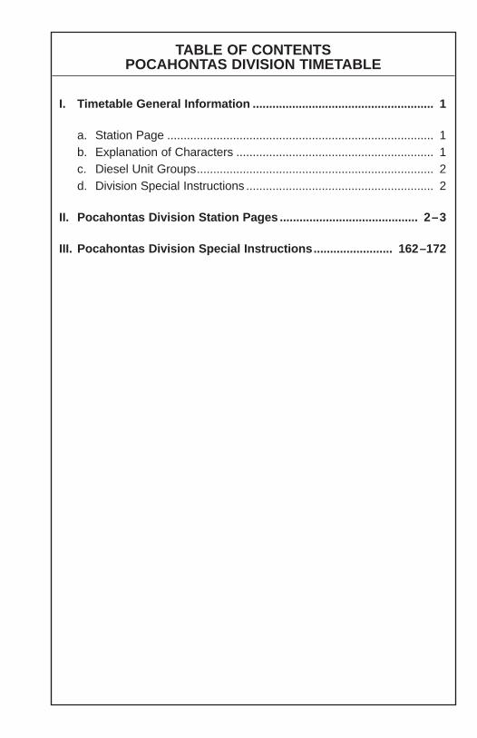
TABLE OF CONTENTSPOCAHONTAS DIVISION TIMETABLE
I. Timetable General Information ....................................................... 1
a. Station Page ................................................................................. 1b. Explanation of Characters ............................................................ 1c. Diesel Unit Groups........................................................................ 2d. Division Special Instructions ......................................................... 2
II. Pocahontas Division Station Pages .......................................... 2–3
III. Pocahontas Division Special Instructions........................ 162–172

This page is intentionally left blank
1
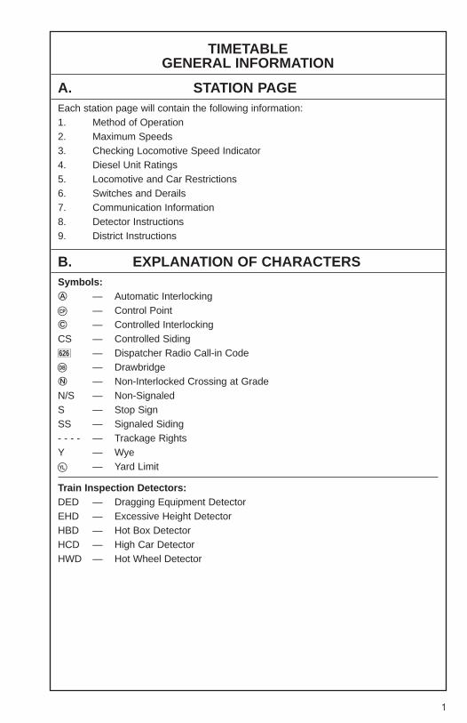
TIMETABLE GENERAL INFORMATION
A. STATION PAGEEach station page will contain the following information:1. Method of Operation2. Maximum Speeds3. Checking Locomotive Speed Indicator4. Diesel Unit Ratings5. Locomotive and Car Restrictions6. Switches and Derails7. Communication Information8. Detector Instructions9. District Instructions
B. EXPLANATION OF CHARACTERSSymbols:� — Automatic Interlocking
— Control Point� — Controlled InterlockingCS — Controlled Siding
— Dispatcher Radio Call-in Code— Drawbridge
� — Non-Interlocked Crossing at GradeN/S — Non-SignaledS — Stop SignSS — Signaled Siding- - - - — Trackage RightsY — Wye
— Yard Limit
Train Inspection Detectors:DED — Dragging Equipment DetectorEHD — Excessive Height DetectorHBD — Hot Box DetectorHCD — High Car DetectorHWD — Hot Wheel Detector
CP�
DB�
YL�
626
2
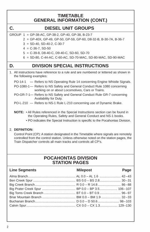
TIMETABLE GENERAL INFORMATION (CONT.)
C. DIESEL UNIT GROUPSGROUP 1 = GP-38-AC, GP-38-2, GP-40, GP-38, B-23-7
2 = GP-40X, GP-49, GP-50, GP-59, GP-60, D8-32-B, B-30-7A, B-36-7 3 = SD-40, SD-40-2, C-30-74 = C-36-7, SD-505 = C-39-8, D8-40-C, D9-40-C, SD-60, SD-706 = SD-80, C-44-AC, C-60-AC, SD-70-MAC, SD-80-MAC, SD-90-MAC
D. DIVISION SPECIAL INSTRUCTIONS1. All instructions have reference to a rule and are numbered or lettered as shown in
the following examples:
PO-14-1 — Refers to NS Operating Rule 14 concerning Engine Whistle Signals.PO-1080-1— Refers to NS Safety and General Conduct Rule 1080 concerning
working on or about Locomotives, Cars or Trains.PO-GR-7-1— Refers to NS Safety and General Conduct Rule GR-7 concerning
Availability for Duty.PO-L-210 — Refers to NS-1 Rule L-210 concerning use of Dynamic Brake.
NOTE: • All Rules referenced in the Special Instructions section can be found inthe Operating Rules, Safety and General Conduct and NS-1 books.
• PO indicates the Special Instruction is specific to the Pocahontas Division.
2. DEFINITION:Control Point (CP): A station designated in the Timetable where signals are remotelycontrolled from the control station. Unless otherwise noted on the station pages, theTrain Dispatcher controls all main tracks and controls all CP’s.
POCAHONTAS DIVISIONSTATION PAGES
Line Segments Milepost Page
Alma Branch...................................................... AL 0.0 – AL 1.6 ........................ 42–43Ben Creek Spur ................................................ BS 0.0 – BS 2.8........................ 30–31Big Creek Branch.............................................. R 0.0 – R 14.8 .......................... 86–88Big Prater Creek Spur ...................................... BP 0.0 – BP 3.5.................... 106–107Big Toms Creek Branch .................................... BT 0.0 – BT 0.9 ........................ 96–97Briar Mountain Branch ...................................... BM 0.0 – BM 1.9 ...................... 32–33Buchanan Branch.............................................. D 0.0 – D 50.6 ........................ 98–103Calvin Spur........................................................ CX 0.0 – CX 1.3.................... 129–130
3
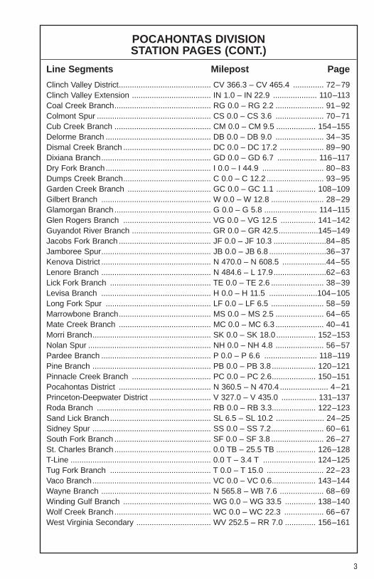
POCAHONTAS DIVISIONSTATION PAGES (CONT.)
Line Segments Milepost Page
Clinch Valley District.......................................... CV 366.3 – CV 465.4 .............. 72–79Clinch Valley Extension .................................... IN 1.0 – IN 22.9 .................... 110–113Coal Creek Branch............................................ RG 0.0 – RG 2.2 ...................... 91–92Colmont Spur .................................................... CS 0.0 – CS 3.6 ...................... 70–71Cub Creek Branch ............................................ CM 0.0 – CM 9.5 .................. 154–155Delorme Branch ................................................ DB 0.0 – DB 9.0 ...................... 34–35Dismal Creek Branch ........................................ DC 0.0 – DC 17.2 .................... 89–90Dixiana Branch.................................................. GD 0.0 – GD 6.7 .................. 116–117Dry Fork Branch................................................ I 0.0 – I 44.9 ............................ 80–83Dumps Creek Branch........................................ C 0.0 – C 12.2 .......................... 93–95Garden Creek Branch ...................................... GC 0.0 – GC 1.1 .................. 108–109Gilbert Branch .................................................. W 0.0 – W 12.8 ........................ 28–29Glamorgan Branch ............................................ G 0.0 – G 5.8 ........................ 114–115Glen Rogers Branch ........................................ VG 0.0 – VG 12.5 ................ 141–142Guyandot River Branch .................................... GR 0.0 – GR 42.5..................145–149Jacobs Fork Branch .......................................... JF 0.0 – JF 10.3 ........................84–85Jamboree Spur.................................................. JB 0.0 – JB 6.8 ..........................36–37Kenova District .................................................. N 470.0 – N 608.5 ....................44–55Lenore Branch .................................................. N 484.6 – L 17.9........................62–63Lick Fork Branch .............................................. TE 0.0 – TE 2.6 ........................ 38–39Levisa Branch .................................................. H 0.0 – H 11.5 ......................104–105Long Fork Spur ................................................ LF 0.0 – LF 6.5 ........................ 58–59Marrowbone Branch.......................................... MS 0.0 – MS 2.5 ...................... 64–65Mate Creek Branch .......................................... MC 0.0 – MC 6.3 ...................... 40–41Morri Branch...................................................... SK 0.0 – SK 18.0 .................. 152–153Nolan Spur ........................................................ NH 0.0 – NH 4.8 ...................... 56–57Pardee Branch .................................................. P 0.0 – P 6.6 ........................ 118–119Pine Branch ...................................................... PB 0.0 – PB 3.8 .................... 120–121Pinnacle Creek Branch .................................... PC 0.0 – PC 2.6.................... 150–151Pocahontas District .......................................... N 360.5 – N 470.4 ...................... 4–21Princeton-Deepwater District ............................ V 327.0 – V 435.0 ................ 131–137Roda Branch .................................................... RB 0.0 – RB 3.3.................... 122–123Sand Lick Branch.............................................. SL 6.5 – SL 10.2 ...................... 24–25Sidney Spur ...................................................... SS 0.0 – SS 7.2........................ 60–61South Fork Branch ............................................ SF 0.0 – SF 3.8 ........................ 26–27St. Charles Branch ............................................ 0.0 TB – 25.5 TB .................. 126–128T-Line ................................................................ 0.0 T – 3.4 T ........................ 124–125Tug Fork Branch .............................................. T 0.0 – T 15.0 .......................... 22–23Vaco Branch...................................................... VC 0.0 – VC 0.6.................... 143–144Wayne Branch .................................................. N 565.8 – WB 7.6 .................... 68–69Winding Gulf Branch ........................................ WG 0.0 – WG 33.5 .............. 138–140Wolf Creek Branch............................................ WC 0.0 – WC 22.3 .................. 66–67West Virginia Secondary .................................. WV 252.5 – RR 7.0 .............. 156–161
4
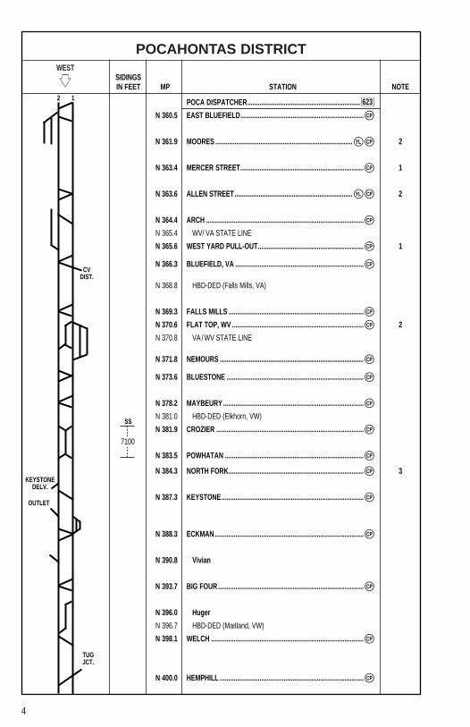
POCAHONTAS DISTRICTWEST
�� SIDINGSIN FEET MP STATION NOTE
POCA DISPATCHER.................................................................
N 360.5 EAST BLUEFIELD.......................................................................
N 361.9 MOORES ............................................................................... 2
N 363.4 MERCER STREET....................................................................... 1
N 363.6 ALLEN STREET.................................................................... 2
N 364.4 ARCH ...........................................................................................
N 365.4 WV/ VA STATE LINE
N 365.6 WEST YARD PULL-OUT............................................................. 1
N 366.3 BLUEFIELD, VA ..........................................................................
N 368.8 HBD-DED (Falls Mills, VA)
N 369.3 FALLS MILLS ..............................................................................
N 370.6 FLAT TOP, WV ............................................................................ 2
N 370.8 VA / WV STATE LINE
N 371.8 NEMOURS ...................................................................................
N 373.6 BLUESTONE ...............................................................................
N 378.2 MAYBEURY .................................................................................
N 381.0 HBD-DED (Elkhorn, VW)
N 381.9 CROZIER .....................................................................................
N 383.5 POWHATAN ................................................................................
N 384.3 NORTH FORK.............................................................................. 3
N 387.3 KEYSTONE..................................................................................
N 388.3 ECKMAN......................................................................................
N 390.8 Vivian
N 393.7 BIG FOUR....................................................................................
N 396.0 Huger
N 396.7 HBD-DED (Maitland, VW)
N 398.1 WELCH ........................................................................................
N 400.0 HEMPHILL ...................................................................................
2 1
CP�
CP�
CP�
CP�
CP�
CP�
CP�
CP�
CP�
CP�
CP�
YL�
YL�
CP�
CP�
CP�
CP�
CP�
CP�
CP�
CP�
CP�
7100
SS
623
CVDIST.
KEYSTONEDELV.
TUGJCT.
OUTLET

5
POCAHONTAS DISTRICTWEST
�� SIDINGSIN FEET MP STATION NOTE
POCA DISPATCHER.................................................................
N 401.1 FARM ...........................................................................................
N 401.4 WHARF ........................................................................................ 2
N 402.8 CAPLES .......................................................................................
N 403.1 MOHEGAN...................................................................................
N 406.7 DAVY............................................................................................
N 410.3 Claren
N 412.6 RODERFIELD ..............................................................................
N 413.0 HBD-DED (Roderfield, WV)
N 417.0 WILMORE ....................................................................................
N 419.3 SANDY HUFF ..............................................................................
N 421.9 HBD-DED (Panther, WV)
N 422.3 IAEGER .....................................................................................Y
N 424.7 HULL ............................................................................................
N 426.4 KROLITZ ......................................................................................
N 429.7 PANTHER ....................................................................................
N 432.5 Alnwick
N 434.6 WAR EAGLE................................................................................
N 437.5 OLD JOE......................................................................................
N 437.8 MINGO .......................................................................................Y 3
N 438.2 WHARNCLIFFE ........................................................................... 3
N 438.4 Ben
N 440.7 GLEN ALUM ................................................................................
CP�
CP�
CP�
CP�
CP�
CP�
CP�
CP�
CP�
CP�
CP�
CP�
CP�
CP�
CP�
CP�
CP�
2 1
7000
SS
11120
SS
DRYFORK
20300
CS
623
GILBERTBR.
LITWARDELV.
SPICE CR.BR.
6
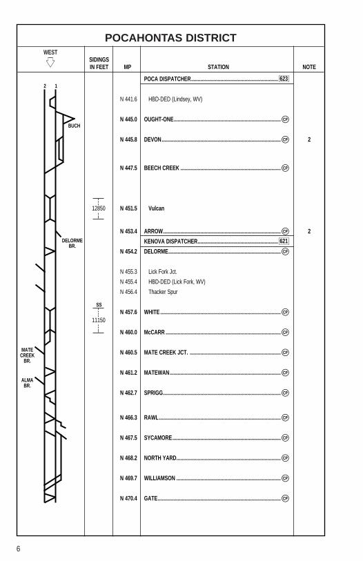
POCAHONTAS DISTRICTWEST
�� SIDINGSIN FEET MP STATION NOTE
POCA DISPATCHER.................................................................
N 441.6 HBD-DED (Lindsey, WV)
N 445.0 OUGHT-ONE................................................................................
N 445.8 DEVON......................................................................................... 2
N 447.5 BEECH CREEK ...........................................................................
N 451.5 Vulcan
N 453.4 ARROW........................................................................................ 2
KENOVA DISPATCHER............................................................
N 454.2 DELORME....................................................................................
N 455.3 Lick Fork Jct.
N 455.4 HBD-DED (Lick Fork, WV)
N 456.4 Thacker Spur
N 457.6 WHITE ..........................................................................................
N 460.0 McCARR ......................................................................................
N 460.5 MATE CREEK JCT. ....................................................................
N 461.2 MATEWAN...................................................................................
N 462.7 SPRIGG........................................................................................
N 466.3 RAWL...........................................................................................
N 467.5 SYCAMORE.................................................................................
N 468.2 NORTH YARD..............................................................................
N 469.7 WILLIAMSON ..............................................................................
N 470.4 GATE............................................................................................
2 1
12850
11150
SS
CP�
CP�
CP�
CP�
CP�
CP�
CP�
CP�
CP�
CP�
CP�
CP�
CP�
CP�
CP�
BUCH
623
621DELORMEBR.
MATECREEK
BR.
ALMABR.
7
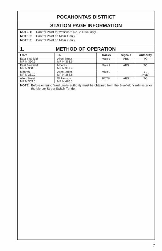
POCAHONTAS DISTRICT
STATION PAGE INFORMATIONNOTE 1: Control Point for westward No. 2 Track only.NOTE 2: Control Point on Main 1 only.NOTE 3: Control Point on Main 2 only.
1. METHOD OF OPERATIONFrom To Tracks Signals AuthorityEast Bluefield Allen Street Main 1 ABS TCMP N 360.5 MP N 363.6East Bluefield Moores Main 2 ABS TCMP N 360.5 MP N 361.9Moores Allen Street Main 2 YLMP N 361.9 MP N 363.6 (Note)Allen Street Williamson BOTH ABS TCMP N 363.6 MP N 470.0NOTE: Before entering Yard Limits authority must be obtained from the Bluefield Yardmaster or
the Mercer Street Switch Tender.

8
POCAHONTAS DISTRICT
2. MAXIMUM SPEEDSMainTrack
Between MPHMP N 360.3, Bluefield Yard and MP N 364.0 25
Except:Virginia Division Pull-In Track 20
MP N 364.0 and MP N 366.2 35MP N 366.2 and MP N 374.8 30
Except:MP N 365.9, Through East Crossover 25MP N 366.2, Through West Crossover 30MP N 369.3, Falls Mills, Through Crossovers 30MP N 372.3 to MP N 372.7, Curves 25MP N 373.6, Bluestone, Through Crossovers 25MP N 373.8, Curve 25
MP N 374.8 and MP N 386.3 40Except:MP N 378.1, Maybeury, Through Crossovers 35MP N 381.9 to MP N 383.4, Powhatan, Through Turnouts and Middle Track 25MP N 383.9, Curve 35MP N 384.7, Curve 35
MP N 386.3 and MP N 394.2 30Except:MP N 386.4 to MP N 387.1, Curves 25MP N 388.2, Eckman, Through Crossovers 25MP N 389.6 to MP N 390.4, Curves 25MP N 393.7, Big Four, Through Crossovers 25
MP N 394.2 and MP N 467.8 35Except:MP N 396.8, Curve 30MP N 398.1, Welch, Through Crossovers 25MP N 400.0, Hemphill, Through Crossover 15MP N 401.1, Farm to MP N 402.9, Through Middle Track 10MP N 403.3, Mohegan, Through Crossover 15MP N 406.7, Davy, Through Crossovers 25MP N 412.8, Roderfield, Through Crossovers 25MP N 417.0, Wilmore to MP N 419.2, Through Turnouts and Middle Track 25MP N 422.3, Iaeger to MP N 426.2, Krolitz, Through Middle Track 20MP N 422.5, Curve 25
MP N 422.7 and MP N 425.0 30

9
POCAHONTAS DISTRICT
2. MAXIMUM SPEEDS (CONT.)MainTrack
Between MPHMP N 425.0 and MP N 467.8 35
Except:MP N 426.4, Krolitz, Through Turnout to Middle Track 20MP N 429.8, Panther, Through Crossovers 35MP N 431.9, Curve 30MP N 434.7, War Eagle, Through Crossover 25MP N 435.1 to MP N 437.4, Curves 30MP N 437.6, Old Joe, Through Crossover 35MP N 440.7, Glen Alum, Through Crossovers 35MP N 445.0, Ought-One, Through Crossover 25MP N 445.1, Curve 25MP N 445.6, Devon and Buch Main Track, Through Turnout 15Buch Main between Ought-One to Beech Creek 15MP N 446.4, Curve 30MP N 447.5, Beech Creek, Through Crossover 15MP N 449.6 to MP N 450.6, Curves 25MP N 453.6, Curve 25MP N 454.2, Delorme, Through Crossovers 35MP N 461.1, Matewan, Through Crossovers 25MP N 462.7, Sprigg, Through Crossover 35MP N 466.2, Rawl, Through East Crossover 25MP N 466.2, Rawl, Through West Crossover 35
MP N 467.8 to MP N 469.5 30Except:MP N 469.7, #2 Station Track Turnout 10
MP N 469.5 to MP N 470.0 25Except:MP N 469.6, Through City Hall Crossover 25MP N 469.7, Through Beckett Crossover 25
10
POCAHONTAS DISTRICT
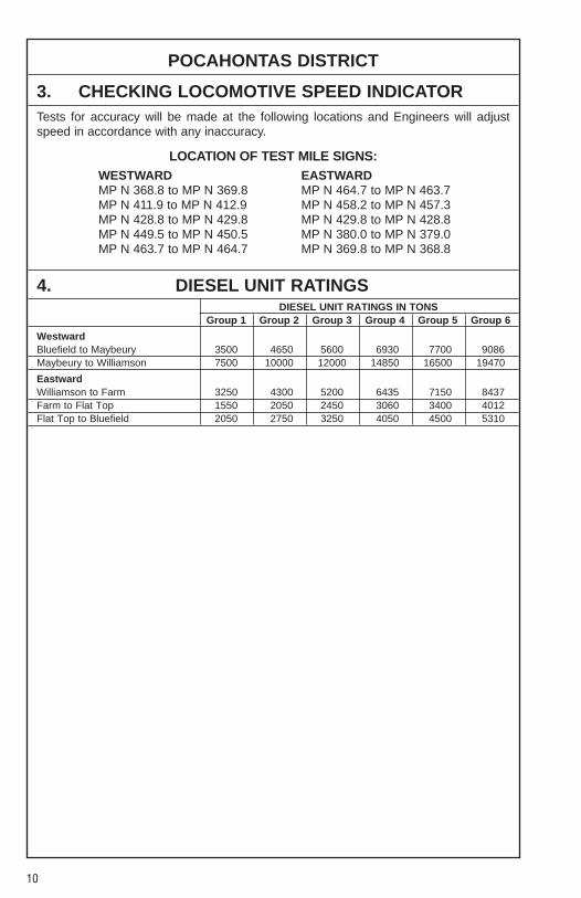
3. CHECKING LOCOMOTIVE SPEED INDICATORTests for accuracy will be made at the following locations and Engineers will adjustspeed in accordance with any inaccuracy.
LOCATION OF TEST MILE SIGNS:WESTWARD EASTWARDMP N 368.8 to MP N 369.8 MP N 464.7 to MP N 463.7MP N 411.9 to MP N 412.9 MP N 458.2 to MP N 457.3MP N 428.8 to MP N 429.8 MP N 429.8 to MP N 428.8MP N 449.5 to MP N 450.5 MP N 380.0 to MP N 379.0MP N 463.7 to MP N 464.7 MP N 369.8 to MP N 368.8
4. DIESEL UNIT RATINGSDIESEL UNIT RATINGS IN TONS
Group 1 Group 2 Group 3 Group 4 Group 5 Group 6
WestwardBluefield to Maybeury 3500 4650 5600 6930 7700 9086Maybeury to Williamson 7500 10000 12000 14850 16500 19470
EastwardWilliamson to Farm 3250 4300 5200 6435 7150 8437Farm to Flat Top 1550 2050 2450 3060 3400 4012Flat Top to Bluefield 2050 2750 3250 4050 4500 5310
11
POCAHONTAS DISTRICT
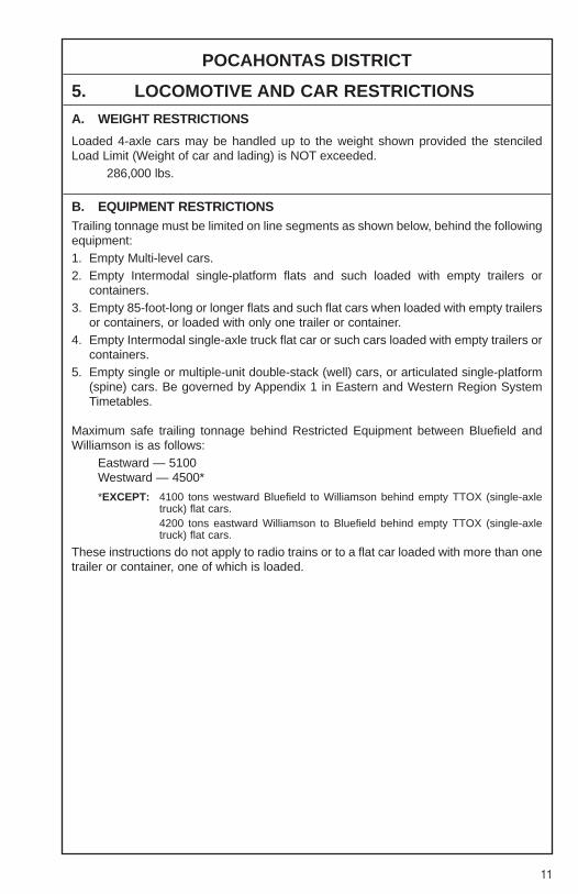
5. LOCOMOTIVE AND CAR RESTRICTIONS
A. WEIGHT RESTRICTIONS
Loaded 4-axle cars may be handled up to the weight shown provided the stenciledLoad Limit (Weight of car and lading) is NOT exceeded.
286,000 lbs.
B. EQUIPMENT RESTRICTIONSTrailing tonnage must be limited on line segments as shown below, behind the followingequipment:1. Empty Multi-level cars.2. Empty Intermodal single-platform flats and such loaded with empty trailers or
containers.3. Empty 85-foot-long or longer flats and such flat cars when loaded with empty trailers
or containers, or loaded with only one trailer or container.4. Empty Intermodal single-axle truck flat car or such cars loaded with empty trailers or
containers.5. Empty single or multiple-unit double-stack (well) cars, or articulated single-platform
(spine) cars. Be governed by Appendix 1 in Eastern and Western Region SystemTimetables.
Maximum safe trailing tonnage behind Restricted Equipment between Bluefield andWilliamson is as follows:
Eastward — 5100Westward — 4500*
*EXCEPT: 4100 tons westward Bluefield to Williamson behind empty TTOX (single-axletruck) flat cars.4200 tons eastward Williamson to Bluefield behind empty TTOX (single-axletruck) flat cars.
These instructions do not apply to radio trains or to a flat car loaded with more than onetrailer or container, one of which is loaded.
12
POCAHONTAS DISTRICT
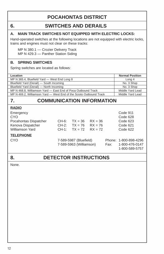
6. SWITCHES AND DERAILS
A. MAIN TRACK SWITCHES NOT EQUIPPED WITH ELECTRIC LOCKS:Hand-operated switches at the following locations are not equipped with electric locks,trains and engines must not clear on these tracks:
MP N 380.1 — Crozier Delivery TrackMP N 429.3 — Panther Station Siding
B. SPRING SWITCHESSpring switches are located as follows:
Location Normal PositionMP N 365.4, Bluefield Yard — West End Long 8 Long 4Bluefield Yard (Derail) — South Incoming No. 3 ShopBluefield Yard (Derail) — North Incoming No. 3 ShopMP N 468.8, Williamson Yard — East End of Poca Outbound Track Middle Yard LeadMP N 469.2, Williamson Yard — West End of the Scioto Outbound Track Middle Yard Lead
7. COMMUNICATION INFORMATIONRADIOEmergency Code 911CYO Code 628Pocahontas Dispatcher CH-6: TX = 36 RX = 36 Code 623Kenova Dispatcher CH-2: TX = 76 RX = 76 Code 621Williamson Yard CH-1: TX = 72 RX = 72 Code 622
TELEPHONECYO 7-589-5987 (Bluefield) Phone: 1-800-898-4296
7-589-5963 (Williamson) Fax: 1-800-476-01471-800-589-5757
8. DETECTOR INSTRUCTIONSNone.
13
POCAHONTAS DISTRICT
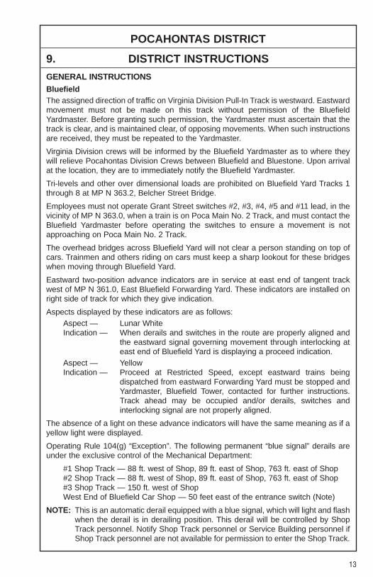
9. DISTRICT INSTRUCTIONS
GENERAL INSTRUCTIONSBluefieldThe assigned direction of traffic on Virginia Division Pull-In Track is westward. Eastwardmovement must not be made on this track without permission of the BluefieldYardmaster. Before granting such permission, the Yardmaster must ascertain that thetrack is clear, and is maintained clear, of opposing movements. When such instructionsare received, they must be repeated to the Yardmaster.
Virginia Division crews will be informed by the Bluefield Yardmaster as to where theywill relieve Pocahontas Division Crews between Bluefield and Bluestone. Upon arrivalat the location, they are to immediately notify the Bluefield Yardmaster.
Tri-levels and other over dimensional loads are prohibited on Bluefield Yard Tracks 1through 8 at MP N 363.2, Belcher Street Bridge.
Employees must not operate Grant Street switches #2, #3, #4, #5 and #11 lead, in thevicinity of MP N 363.0, when a train is on Poca Main No. 2 Track, and must contact theBluefield Yardmaster before operating the switches to ensure a movement is notapproaching on Poca Main No. 2 Track.
The overhead bridges across Bluefield Yard will not clear a person standing on top ofcars. Trainmen and others riding on cars must keep a sharp lookout for these bridgeswhen moving through Bluefield Yard.
Eastward two-position advance indicators are in service at east end of tangent trackwest of MP N 361.0, East Bluefield Forwarding Yard. These indicators are installed onright side of track for which they give indication.
Aspects displayed by these indicators are as follows:Aspect — Lunar WhiteIndication — When derails and switches in the route are properly aligned and
the eastward signal governing movement through interlocking ateast end of Bluefield Yard is displaying a proceed indication.
Aspect — YellowIndication — Proceed at Restricted Speed, except eastward trains being
dispatched from eastward Forwarding Yard must be stopped andYardmaster, Bluefield Tower, contacted for further instructions.Track ahead may be occupied and/or derails, switches andinterlocking signal are not properly aligned.
The absence of a light on these advance indicators will have the same meaning as if ayellow light were displayed.
Operating Rule 104(g) “Exception”. The following permanent “blue signal” derails areunder the exclusive control of the Mechanical Department:
#1 Shop Track — 88 ft. west of Shop, 89 ft. east of Shop, 763 ft. east of Shop#2 Shop Track — 88 ft. west of Shop, 89 ft. east of Shop, 763 ft. east of Shop#3 Shop Track — 150 ft. west of ShopWest End of Bluefield Car Shop — 50 feet east of the entrance switch (Note)
NOTE: This is an automatic derail equipped with a blue signal, which will light and flashwhen the derail is in derailing position. This derail will be controlled by ShopTrack personnel. Notify Shop Track personnel or Service Building personnel ifShop Track personnel are not available for permission to enter the Shop Track.
14
POCAHONTAS DISTRICT
9. DISTRICT INSTRUCTIONS (CONT.)
GENERAL INSTRUCTIONS (CONT.)Engine Service Tracks
South Incoming — 568 ft. west of Service Bldg.North Incoming — 568 ft. west of Service Bldg.Sand Track — At east end of Sand Track switchGate Track — 682 ft. east of Gate Track switchNOTE: Split point derail (spring loaded) west end of Poca Outgoing and yard
Engine tracks.
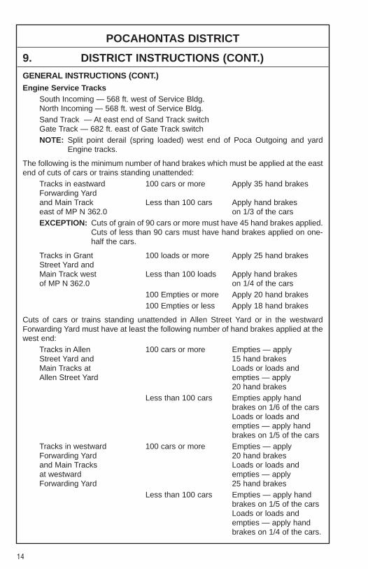
The following is the minimum number of hand brakes which must be applied at the eastend of cuts of cars or trains standing unattended:
Tracks in eastward 100 cars or more Apply 35 hand brakesForwarding Yard and Main Track Less than 100 cars Apply hand brakeseast of MP N 362.0 on 1/3 of the carsEXCEPTION: Cuts of grain of 90 cars or more must have 45 hand brakes applied.
Cuts of less than 90 cars must have hand brakes applied on one-half the cars.
Tracks in Grant 100 loads or more Apply 25 hand brakesStreet Yard and Main Track west Less than 100 loads Apply hand brakesof MP N 362.0 on 1/4 of the cars
100 Empties or more Apply 20 hand brakes100 Empties or less Apply 18 hand brakes
Cuts of cars or trains standing unattended in Allen Street Yard or in the westwardForwarding Yard must have at least the following number of hand brakes applied at thewest end:
Tracks in Allen 100 cars or more Empties — apply Street Yard and 15 hand brakesMain Tracks at Loads or loads and Allen Street Yard empties — apply
20 hand brakesLess than 100 cars Empties apply hand
brakes on 1/6 of the carsLoads or loads andempties — apply handbrakes on 1/5 of the cars
Tracks in westward 100 cars or more Empties — apply Forwarding Yard 20 hand brakesand Main Tracks Loads or loads and at westward empties — apply Forwarding Yard 25 hand brakes
Less than 100 cars Empties — apply handbrakes on 1/5 of the carsLoads or loads andempties — apply handbrakes on 1/4 of the cars.
15
POCAHONTAS DISTRICT
9. DISTRICT INSTRUCTIONS (CONT.)
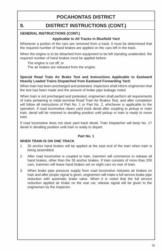
GENERAL INSTRUCTIONS (CONT.)Applicable to All Tracks in Bluefield Yard
Whenever a portion of the cars are removed from a track, it must be determined thatthe required number of hand brakes are applied on the cars left in the track.
When the engine is to be detached from equipment to be left standing unattended, therequired number of hand brakes must be applied before:
The engine is cut off; orThe air brakes are released from the engine.
Special Road Train Air Brake Test and Instructions Applicable to EastwardHeavily Loaded Trains Dispatched from Eastward Forwarding Yard:When train has been precharged and pretested, inspectors shall inform enginemen thatthe test has been made and the amount of brake pipe leakage noted.
When train is not precharged and pretested, enginemen shall perform all requirementsof rules pertaining to initial terminal Road Train Air Brakes Test, and after completionwill follow all instructions of Part No. 1 or Part No. 2, whichever is applicable to theoperation. If road locomotive clears yard track derail after coupling to pickup or maintrain, derail will be restored to derailing position until pickup or train is ready to moveeast.
If road locomotive does not clear yard track derail, Train Dispatcher will keep No. 17derail in derailing position until train is ready to depart.
Part No. 1WHEN TRAIN IS ON ONE TRACK1. 35 anchor hand brakes will be applied at the east end of the train when train is
being assembled.
2. After road locomotive is coupled to train, trainmen will commence to release allhand brakes, other than the 35 anchor brakes. If train consists of more than 200cars, trainmen will leave hand brakes set on eight cars on rear of train.
3. When brake pipe pressure supply from road locomotive releases air brakes ontrain and after proper signal is given, enginemen will make a full service brake pipereduction with automatic brake valve. When it is noted that the full servicereduction applied air brake on the rear car, release signal will be given to theenginemen by the inspector.
16
POCAHONTAS DISTRICT
9. DISTRICT INSTRUCTIONS (CONT.)
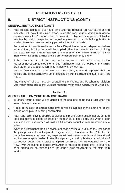
GENERAL INSTRUCTIONS (CONT.)4. After release signal is given and air brake has released on rear car, rear end
inspector will note brake pipe pressure on the rear gauge. When rear gaugepressure rises to 65 pounds and remains 65 or higher for a period of twelveminutes by watch, inspector will signal engineman to apply holding brake. Aholding brake is a service brake pipe reduction of 12 pounds.Permission will be obtained from the Train Dispatcher for train to depart, and whenroute is lined, holding brake will be applied. After the route is lined and holdingbrake applied, trainman will release hand brakes on the head end and on rear oftrain. When all of the anchor brakes are released, train may depart.
5. If the train starts to roll out prematurely, engineman will make a brake pipereduction necessary to stop the roll-out. Yardmaster must be notified of the train’spremature roll-out, and he will, in turn, notify all concerned.After sufficient anchor hand brakes are reapplied, rear end inspector shall benotified and all concerned will commence again with instructions of Item Four, PartNo. 1.
Any cases of roll-out must be reported to the Virginia and Pocahontas DivisionSuperintendents and to the Division Manager Mechanical Operators at Bluefield.
Part No. 2WHEN TRAIN IS ON MORE THAN ONE TRACK1. 35 anchor hand brakes will be applied at the east end of the main train when the
train is being assembled.
2. Required number of anchor hand brakes will be applied at the east end of thepickup when pickup is being assembled.
3. After road locomotive is coupled to pickup and brake pipe pressure supply air fromroad locomotive releases air brake on the rear car of the pickup, and when propersignal is given, engineman will make a full service reduction with automatic brakevalve.When it is known that the full service reduction applied air brake on the rear car ofthe pickup, inspector will signal the engineman to release air brakes. After the airbrake has released on rear car, inspector will wait seven minutes and then signalengineman to apply holding brake. For a pickup, a holding brake is a reduction ofsix pounds. After holding brake is applied, permission will be obtained from theNew River Dispatcher to double over. After permission to double over is obtained,hand brakes will be released and the double over movement to the main trainmade.
17
POCAHONTAS DISTRICT
9. DISTRICT INSTRUCTIONS (CONT.)
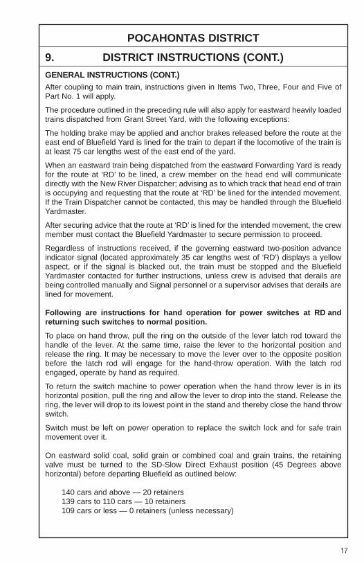
GENERAL INSTRUCTIONS (CONT.)After coupling to main train, instructions given in Items Two, Three, Four and Five ofPart No. 1 will apply.
The procedure outlined in the preceding rule will also apply for eastward heavily loadedtrains dispatched from Grant Street Yard, with the following exceptions:
The holding brake may be applied and anchor brakes released before the route at theeast end of Bluefield Yard is lined for the train to depart if the locomotive of the train isat least 75 car lengths west of the east end of the yard.
When an eastward train being dispatched from the eastward Forwarding Yard is readyfor the route at ‘RD’ to be lined, a crew member on the head end will communicatedirectly with the New River Dispatcher; advising as to which track that head end of trainis occupying and requesting that the route at ‘RD’ be lined for the intended movement.If the Train Dispatcher cannot be contacted, this may be handled through the BluefieldYardmaster.
After securing advice that the route at ‘RD’ is lined for the intended movement, the crewmember must contact the Bluefield Yardmaster to secure permission to proceed.
Regardless of instructions received, if the governing eastward two-position advanceindicator signal (located approximately 35 car lengths west of ‘RD’) displays a yellowaspect, or if the signal is blacked out, the train must be stopped and the BluefieldYardmaster contacted for further instructions, unless crew is advised that derails arebeing controlled manually and Signal personnel or a supervisor advises that derails arelined for movement.
Following are instructions for hand operation for power switches at RD andreturning such switches to normal position.
To place on hand throw, pull the ring on the outside of the lever latch rod toward thehandle of the lever. At the same time, raise the lever to the horizontal position andrelease the ring. It may be necessary to move the lever over to the opposite positionbefore the latch rod will engage for the hand-throw operation. With the latch rodengaged, operate by hand as required.
To return the switch machine to power operation when the hand throw lever is in itshorizontal position, pull the ring and allow the lever to drop into the stand. Release thering, the lever will drop to its lowest point in the stand and thereby close the hand throwswitch.
Switch must be left on power operation to replace the switch lock and for safe trainmovement over it.
On eastward solid coal, solid grain or combined coal and grain trains, the retainingvalve must be turned to the SD-Slow Direct Exhaust position (45 Degrees abovehorizontal) before departing Bluefield as outlined below:
140 cars and above — 20 retainers139 cars to 110 cars — 10 retainers109 cars or less — 0 retainers (unless necessary)

18
POCAHONTAS DISTRICT
9. DISTRICT INSTRUCTIONS (CONT.)
GENERAL INSTRUCTIONS (CONT.)Due to the construction of permanent freight car work platforms (scaffolds), closeclearance conditions exist on No. 2 and No. 3 Shop Tracks, Bluefield Car Shop,Bluefield, WV, immediately east of the Car Shop Building, and employees are prohibitedfrom riding sides or end of equipment on these tracks. Only NW Open Top systemhoppers should be spotted on No. 3 Track. Close clearance signs have been erected.
Close clearance exists between the following tracks in Bluefield Yard when cars orequipment are on adjacent tracks:
Tracks 5 through 10 Grant Street YardTracks 1, 2, 3 Pocket located just east of East Yard signal
Employees should not ride on sides or ends of equipment in these tracks.
In Bluefield Yard, between Arch Crossover, MP N 364.6, and Mercer Street,MP N 363.4, normal position for switches on Motor Car Track is lined for movement onthe Motor Car Track. Between these points on Track No. 1, normal position for switchesis lined for movement on Track No. 1. All switches on the Motor Car Track and TrackNo. 1 between Arch Crossover and Mercer Street, after being used, must be left linedin normal position.
No-Whistling Ordinance in effect through city limits of Bluefield, VA, all hours exceptas may be necessary for transmission of signals and in case of emergency to preventaccident.
When approaching grade crossings, engine bell must be rung and ditch lights flashingstarting not less than 300 yards nor more than 600 yards in advance of crossing, andmust be rung continuously until the engine occupies the crossing.
While passing Shop Tracks on the Radford Pull-In, Engine Running Track and #8 GrantSt. Yard, engine bell must be rung continuously to warn shop employees of movement.
Pocahontas DistrictAll eastward trains and engines stopping to change crews, or held by signal indicationor Train Dispatcher at Falls Mills Road Crossing, must stop west of the Begin Test MileSign, MP N 369.8, and remain there until instructed by Train Dispatcher to proceed.Orange painted rubber “stops”, approximately 6 inches by 8 inches, are attached to thecrosstie on Main 1 immediately adjacent to the Begin Test Mile Sign. Trains and enginesshould not stop between the orange “stops” and Falls Mills Road Crossing.
When snow or ice is present, trains and engines stopping to change crews maydisregard rubber “stops” and are permitted to stop within short walking distance of FallsMills Road Crossing to swap crews. A distance approximately 100 feet west of thecrossing when snow and ice is present will allow crossing gates to time out and raise.
Engineers of westward trains stopped at Stop signal on Main 2 at North Fork, will stoptheir trains to clear crossing at MP N 384.3. Westward crews setting off empties in thevicinity of North Fork will leave detached portion of train east of highway crossing toavoid blocking same.

19
POCAHONTAS DISTRICT
9. DISTRICT INSTRUCTIONS (CONT.)
GENERAL INSTRUCTIONS (CONT.)Pocahontas District (Cont.)
All Pocahontas District Conductors will contact Yardmaster at Auville Yard Office,laeger, WV, prior to setting off any and all non-coal traffic cars destined within theWilcoe-Auville Territories. Examples of such non-coal traffic cars are:1. Empty gondolas of any type2. Company material3. Covered hoppers, either loaded or empty, and4. Any other non-coal traffic cars not herein listed.
Engines must not be operated under overhead tipple at:Dans Branch Tipple, MP ED 0.4, Dans Branch.
Flag protection must be provided when trains or engines are operated over Rt. 52/Sec. 9 crossing, MP ED 0.0 + 390 feet, Dans Branch.
When delivering empties to Lake Superior, MP N 396.5, observe the followinginstructions:1. Do not take units more than 1 car length above the drop-in switch2. Empty steel coal hoppers are limited to 50 car cuts3. Empty aluminum coal hoppers are limited to 40 car cuts4. Do not handle any cars other than empty coal hoppers across the main line
delivery switch when delivering empties5. Do not make abrupt throttle changes when moving through the main line delivery
switch.
When delivering Keystone Mine, MP N 387.0, do not take units west of orange paintedtie, just west of the derail in the delivery track, when spotting empties. It is permissibleto leave cars less than one car length from the clearance point.
Eastward trains stopping at Davy, MP N 406.7, should arrange to stop approximately250 feet west of School St. Road Crossing, MP N 407.0. If signal cannot be viewed afterstopping, request Train Dispatcher to notify crew when ready for train to proceed east,being governed at Davy.
Crews picking up empty boxcars for Gilco Lumber will make certain that they aredouble-doored cars. Gilco Lumber cannot load single-doored boxcars account theycannot get their forklift inside car. Notify Yardmaster on duty if you are instructed to pickup cars at a specific location that are single-doored for disposition of such cars.
All eastward trains approaching Alnwick having a mixed consist of (3) Hi-Ad units GE-EMD combination, will reduce the throttle setting to 7th notch between MP N 434.0and MP N 432.5.
Cars or engines left standing in Vulcan Middle Track must not be left less than 250 feetfrom the crossing at MP N 451.3. Yellow markings have been painted to indicate thisclearance limit.

20
POCAHONTAS DISTRICT
9. DISTRICT INSTRUCTIONS (CONT.)
GENERAL INSTRUCTIONS (CONT.)Pocahontas District (Cont.)
Eastward train or engine movements on Main 2 receiving Approach Diverging atMP N 462.8 and Diverging Approach at signal located at MP N 461.2 will proceedpreparing to take the diverging route onto Mate Creek Branch at a speed not exceeding15 MPH, unless diverging route is taken onto Main 1 at the Matewan Crossover at aspeed not to exceed 25 MPH.
Reference NS-1 Rule A-31 concerning requirements for Two-Way End-Of-Train-Devices. The following sections of track have an average grade of 2 percent or greaterover a distance of two continuous miles, or an average grade of 1 percent or greaterover a distance of three continuous miles.
Pocahontas District Milepost Length (Miles) Grade-Avg%N 360.3 to N 363.3 3.0 1.40N 363.2 to N 366.2 3.0 1.11N 375.1 to N 385.0 9.9 1.27
Williamson YardAn electric control derail is in service at MP N 469.3. Derail is located between theMiddle Yard Lead and Inbound Service Tracks 1, 2 & 3.
Three electric control derails are in service, one at east end of Scioto Inbound Track,located 150 feet west of No. 1 Shop Track switch, one at east end of East Middle Track,located 180 feet west of Middle Track switch and one at the Poca Outbound SparkTrack, located 150 feet west of the Poca Outbound Switch. Control of these derails willbe made by contacting Williamson Service Building by radio.
Operating Rule 104(g) “Exception”. The following permanent “blue signal” derails areunder the exclusive control of the Mechanical Department.
When leaving cars on the west end of, 2 in the north, you are instructed to leave thecars east of, 3 & 4 in the north, switches.
Close clearances exist between Tracks 8 & 9 in the east yard located between 9 & 10switch on the east end. Exercise due caution when working in this area.
ATTENTION — Remote Control Locomotives operate in this area. Locomotive cabsmay be unoccupied. When working in Williamson Yard, handling switches other thanthose on approved route must be cleared with Yardmaster.
21
POCAHONTAS DISTRICT
9. DISTRICT INSTRUCTIONS (CONT.)
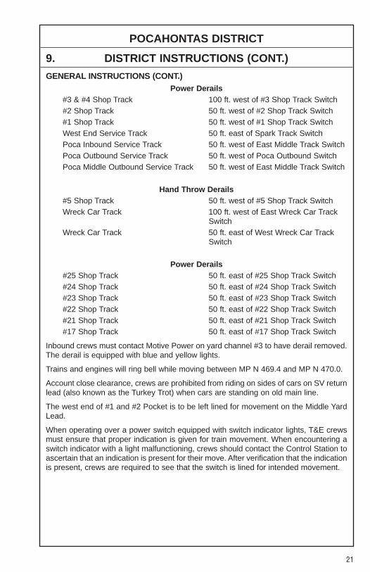
GENERAL INSTRUCTIONS (CONT.)Power Derails
#3 & #4 Shop Track 100 ft. west of #3 Shop Track Switch#2 Shop Track 50 ft. west of #2 Shop Track Switch#1 Shop Track 50 ft. west of #1 Shop Track SwitchWest End Service Track 50 ft. east of Spark Track SwitchPoca Inbound Service Track 50 ft. west of East Middle Track SwitchPoca Outbound Service Track 50 ft. west of Poca Outbound SwitchPoca Middle Outbound Service Track 50 ft. west of East Middle Track Switch
Hand Throw Derails#5 Shop Track 50 ft. west of #5 Shop Track SwitchWreck Car Track 100 ft. west of East Wreck Car Track
SwitchWreck Car Track 50 ft. east of West Wreck Car Track
Switch
Power Derails#25 Shop Track 50 ft. east of #25 Shop Track Switch#24 Shop Track 50 ft. east of #24 Shop Track Switch#23 Shop Track 50 ft. east of #23 Shop Track Switch#22 Shop Track 50 ft. east of #22 Shop Track Switch#21 Shop Track 50 ft. east of #21 Shop Track Switch#17 Shop Track 50 ft. east of #17 Shop Track Switch
Inbound crews must contact Motive Power on yard channel #3 to have derail removed.The derail is equipped with blue and yellow lights.
Trains and engines will ring bell while moving between MP N 469.4 and MP N 470.0.
Account close clearance, crews are prohibited from riding on sides of cars on SV returnlead (also known as the Turkey Trot) when cars are standing on old main line.
The west end of #1 and #2 Pocket is to be left lined for movement on the Middle YardLead.
When operating over a power switch equipped with switch indicator lights, T&E crewsmust ensure that proper indication is given for train movement. When encountering aswitch indicator with a light malfunctioning, crews should contact the Control Station toascertain that an indication is present for their move. After verification that the indicationis present, crews are required to see that the switch is lined for intended movement.

22
TUG FORK BRANCHWEST
�� SIDINGSIN FEET MP STATION NOTE
POCA DISPATCHER.................................................................
N 400.0/T 0.0 HEMPHILL 1
T 3.5 WILCOE ....................................................................................... 2
T 6.8 GARY.........................................................................................Y 2
T 12.4 SOUTH FORK
T 15.0 PAGETON
STATION PAGE INFORMATIONNOTE 1: At Hemphill use the single tone for the Pocahontas Dispatcher. Use the double tone
for the Auville Yardmaster.NOTE 2: Authority to occupy the Main Track within Yard Limits at Wilcoe must be obtained from
the Auville Yardmaster.Trains clearing Wilcoe Yard Limits will report clear to the Auville Yardmaster.
1. METHOD OF OPERATIONFrom To Tracks Signals AuthorityHemphill Wilcoe Main N/S TWCMP T 0.0 MP T 3.5Wilcoe Gary Main N/S YLMP T 3.5 MP T 6.8Gary South Fork Main N/S TWCMP T 6.8 MP T 12.4South Fork Pageton 105MP T 12.4 MP T 15.0
2. MAXIMUM SPEEDSMainTrack
Between MPHMP T 0.0 and MP T 4.0 15MP T 4.0 and MP T 15.0 10
3. CHECKING LOCOMOTIVE SPEED INDICATORTests for accuracy will be made at the following locations and Engineers will adjustspeed in accordance with any inaccuracy.
LOCATION OF TEST MILE SIGNS:None.
YL�
YL�
623
SAND
LICK BR.
POCA MAIN

23
TUG FORK BRANCH
4. DIESEL UNIT RATINGSDIESEL UNIT RATINGS IN TONS
Group 1 Group 2 Group 3 Group 4 Group 5 Group 6
WestwardWilcoe to Hemphill 5000 6650 8000 9900 11000 12980
5. LOCOMOTIVE AND CAR RESTRICTIONS
EQUIPMENT RESTRICTIONSPlate “C” and cars exceeding Plate “C” must not be handled on Tug Fork Branch.
6. SWITCHES AND DERAILSNone.
7. COMMUNICATION INFORMATIONAuville Yardmaster CH-6: TX = 36 RX = 36 Code 631Pocahontas Dispatcher CH-6: TX = 36 RX = 36 Code 623
8. DETECTOR INSTRUCTIONSNone.
9. DISTRICT INSTRUCTIONSDivision Wide Instruction PO-L-245[1]-(1) for trains operating on heavy descendinggrades applies.

24
SAND LICK BRANCHWEST
�� SIDINGSIN FEET MP STATION NOTE
POCA DISPATCHER.................................................................
T 6.5/SL 6.7 SAND LICK .............................................................................. Y 1
SL 10.2 FILBERT
STATION PAGE INFORMATIONNOTE 1: Yard Limits begin at Sand Lick, MP SL 6.7 to Wilcoe, MP T 3.5.
1. METHOD OF OPERATIONFrom To Tracks Signals AuthoritySand Lick Filbert Main N/S TWCMP SL 6.7 MP SL 10.2
2. MAXIMUM SPEEDSMainTrack
Between MPHMP SL 6.7 and MP SL 10.2 10
3. CHECKING LOCOMOTIVE SPEED INDICATORTests for accuracy will be made at the following locations and Engineers will adjustspeed in accordance with any inaccuracy.
LOCATION OF TEST MILE SIGNS:None.
4. DIESEL UNIT RATINGSNone.
623
YL�
TUG FORK
25
SAND LICK BRANCH
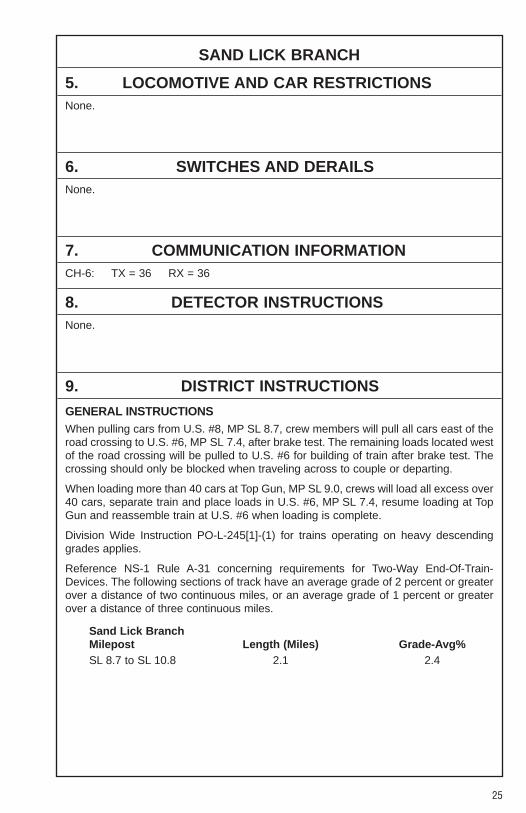
5. LOCOMOTIVE AND CAR RESTRICTIONSNone.
6. SWITCHES AND DERAILSNone.
7. COMMUNICATION INFORMATIONCH-6: TX = 36 RX = 36
8. DETECTOR INSTRUCTIONSNone.
9. DISTRICT INSTRUCTIONS
GENERAL INSTRUCTIONSWhen pulling cars from U.S. #8, MP SL 8.7, crew members will pull all cars east of theroad crossing to U.S. #6, MP SL 7.4, after brake test. The remaining loads located westof the road crossing will be pulled to U.S. #6 for building of train after brake test. Thecrossing should only be blocked when traveling across to couple or departing.
When loading more than 40 cars at Top Gun, MP SL 9.0, crews will load all excess over40 cars, separate train and place loads in U.S. #6, MP SL 7.4, resume loading at TopGun and reassemble train at U.S. #6 when loading is complete.
Division Wide Instruction PO-L-245[1]-(1) for trains operating on heavy descendinggrades applies.
Reference NS-1 Rule A-31 concerning requirements for Two-Way End-Of-Train-Devices. The following sections of track have an average grade of 2 percent or greaterover a distance of two continuous miles, or an average grade of 1 percent or greaterover a distance of three continuous miles.
Sand Lick BranchMilepost Length (Miles) Grade-Avg%SL 8.7 to SL 10.8 2.1 2.4

26
SOUTH FORK BRANCHWEST
�� SIDINGSIN FEET MP STATION NOTE
POCA DISPATCHER.................................................................
T 12.3/SF 0.0 SOUTH FORK
SF 3.8 MUNSON
SF 5.3 END OF LINE
1. METHOD OF OPERATIONFrom To Tracks Signals AuthoritySouth Fork Munson Main N/S TWCMP SF 0.0 MP SF 3.8Munson End of Line 105MP SF 3.8 MP SF 5.3
2. MAXIMUM SPEEDSMainTrack
Between MPHMP SF 0.0 and MP SF 5.3 10
3. CHECKING LOCOMOTIVE SPEED INDICATORTests for accuracy will be made at the following locations and Engineers will adjustspeed in accordance with any inaccuracy.
LOCATION OF TEST MILE SIGNS:None.
4. DIESEL UNIT RATINGSNone.
5. LOCOMOTIVE AND CAR RESTRICTIONSNone.
623TUG FORK
27
SOUTH FORK BRANCH
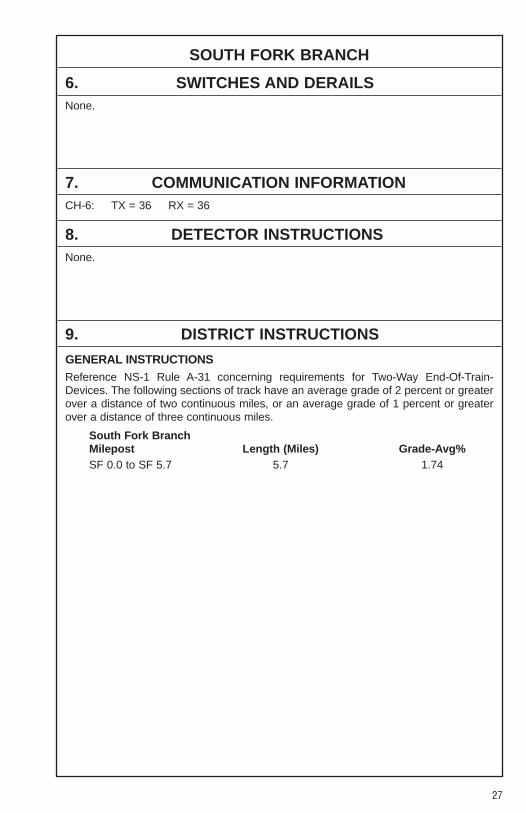
6. SWITCHES AND DERAILSNone.
7. COMMUNICATION INFORMATIONCH-6: TX = 36 RX = 36
8. DETECTOR INSTRUCTIONSNone.
9. DISTRICT INSTRUCTIONS
GENERAL INSTRUCTIONSReference NS-1 Rule A-31 concerning requirements for Two-Way End-Of-Train-Devices. The following sections of track have an average grade of 2 percent or greaterover a distance of two continuous miles, or an average grade of 1 percent or greaterover a distance of three continuous miles.
South Fork BranchMilepost Length (Miles) Grade-Avg%SF 0.0 to SF 5.7 5.7 1.74

28
GILBERT BRANCHWEST
�� SIDINGSIN FEET MP STATION NOTE
POCA DISPATCHER.................................................................
GR 42.5/W 11.4 NEDS............................................................................................
W 7.7 Scaggs
W 4.2 BEN CREEK ................................................................................
W 3.2 PEKIN...........................................................................................
W 0.6 JERRY..........................................................................................
W 0.0/ WHARNCLIFFE ...........................................................................N 438.2
1. METHOD OF OPERATIONFrom To Tracks Signals AuthorityNeds Wharncliffe Single ABS TCMP W 11.4 MP W 0.0
2. MAXIMUM SPEEDSMainTrack
Between MPHMP W 0.0 and MP W 3.0 25MP W 3.0 and MP W 11.4 20
3. CHECKING LOCOMOTIVE SPEED INDICATORTests for accuracy will be made at the following locations and Engineers will adjustspeed in accordance with any inaccuracy.
LOCATION OF TEST MILE SIGNS:None.
4. DIESEL UNIT RATINGSDIESEL UNIT RATINGS IN TONS
Group 1 Group 2 Group 3 Group 4 Group 5 Group 6
WestwardGilbert to Staggerweed 2500 3350 4000 4950 5500 6490
EastwardWharncliffe to Staggerweed 1600 2150 2550 3150 3500 4130
5000
CSX
CP�
CP�
CP�
CP�
CP�
SS
623
BENCREEK
POCA MAIN

29
GILBERT BRANCH
5. LOCOMOTIVE AND CAR RESTRICTIONS
WEIGHT RESTRICTIONS
Loaded 4-axle cars may be handled up to the weight shown provided the stenciledLoad Limit (Weight of car and lading) is NOT exceeded.
286,000 lbs.
6. SWITCHES AND DERAILS
MAIN TRACK SWITCHES NOT EQUIPPED WITH ELECTRIC LOCKS:Hand-operated switches at the following locations are not equipped with electric locks,trains and engines must not clear on these tracks:
MP W 0.3 — Wharncliffe Sta. Sdg. MP W 6.0 and MP W 7.8 — Scaggs
7. COMMUNICATION INFORMATIONCH-6: TX = 36 RX = 36NEDS Station — EB under control of PD Dispatcher and
WB under control of Poca Dispatcher
8. DETECTOR INSTRUCTIONSNone.
9. DISTRICT INSTRUCTIONS
GENERAL INSTRUCTIONSReference NS-1 Rule A-31 concerning requirements for Two-Way End-Of-Train-Devices. The following sections of track have an average grade of 2 percent or greaterover a distance of two continuous miles, or an average grade of 1 percent or greaterover a distance of three continuous miles.
Gilbert BranchMilepost Length (Miles) Grade-Avg%W 0.8 to W 4.4 3.6 1.00

30
BEN CREEK SPURWEST
�� SIDINGSIN FEET MP STATION NOTE
POCA DISPATCHER.................................................................
W 4.2/BS 0.0 BEN CREEK ................................................................................
BS 1.5 TIMBAR
1. METHOD OF OPERATIONFrom To Tracks Signals AuthorityBen Creek Jct. Timbar Main N/S TWCMP BS 0.0 MP BS 1.5
2. MAXIMUM SPEEDSMainTrack
Between MPHMP BS 0.0 and MP BS 1.5 15
3. CHECKING LOCOMOTIVE SPEED INDICATORTests for accuracy will be made at the following locations and Engineers will adjustspeed in accordance with any inaccuracy.
LOCATION OF TEST MILE SIGNS:None.
4. DIESEL UNIT RATINGSNone.
5. LOCOMOTIVE AND CAR RESTRICTIONSNone.
CP�
623
31
BEN CREEK SPUR
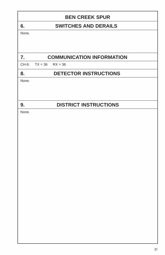
6. SWITCHES AND DERAILSNone.
7. COMMUNICATION INFORMATIONCH-6: TX = 36 RX = 36
8. DETECTOR INSTRUCTIONSNone.
9. DISTRICT INSTRUCTIONSNone.
32
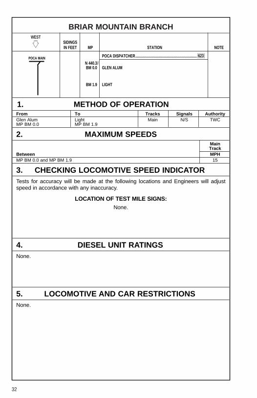
BRIAR MOUNTAIN BRANCHWEST
�� SIDINGSIN FEET MP STATION NOTE
POCA DISPATCHER.................................................................
N 440.3/BM 0.0 GLEN ALUM
BM 1.9 LIGHT
1. METHOD OF OPERATIONFrom To Tracks Signals AuthorityGlen Alum Light Main N/S TWCMP BM 0.0 MP BM 1.9
2. MAXIMUM SPEEDSMainTrack
Between MPHMP BM 0.0 and MP BM 1.9 15
3. CHECKING LOCOMOTIVE SPEED INDICATORTests for accuracy will be made at the following locations and Engineers will adjustspeed in accordance with any inaccuracy.
LOCATION OF TEST MILE SIGNS:None.
4. DIESEL UNIT RATINGSNone.
5. LOCOMOTIVE AND CAR RESTRICTIONSNone.
623POCA MAIN

33
BRIAR MOUNTAIN BRANCH
6. SWITCHES AND DERAILSNone.
7. COMMUNICATION INFORMATIONCH-6: TX = 36 RX = 36
8. DETECTOR INSTRUCTIONSNone.
9. DISTRICT INSTRUCTIONS
GENERAL INSTRUCTIONSDivision Wide Instruction PO-L-245[1]-(1) for trains operating on heavy descendinggrades applies.
Switch Point Derail at MP BM 2.3 may be left locked in non-derailing position when notprotecting unattended equipment. Crews must approach this location expecting to findthe derail in derailing position.
Reference NS-1 Rule A-31 concerning requirements for Two-Way End-Of-Train-Devices. The following sections of track have an average grade of 2 percent or greaterover a distance of two continuous miles, or an average grade of 1 percent or greaterover a distance of three continuous miles.
Briar Mtn. BranchMilepost Length (Miles) Grade-Avg%BM 0.0 to BM 3.9 3.9 2.21

34
DELORME BRANCHWEST
�� SIDINGSIN FEET MP STATION NOTE
POCA DISPATCHER.................................................................
N 453.4/DB 0.0 ARROW
DB 5.5 PHELPS
DB 9.0 THOMAS
1. METHOD OF OPERATIONFrom To Tracks Signals AuthorityArrow Thomas Main N/S TWCMP DB 0.0 MP DB 9.0
2. MAXIMUM SPEEDSMainTrack
Between MPHMP DB 0.0 and MP DB 2.0 15MP DB 2.0 and MP DB 6.4 20MP DB 6.4 and MP DB 9.0 15
3. CHECKING LOCOMOTIVE SPEED INDICATORTests for accuracy will be made at the following locations and Engineers will adjustspeed in accordance with any inaccuracy.
LOCATION OF TEST MILE SIGNS:None.
4. DIESEL UNIT RATINGSNone.
623
JAMBOREESPUR
35
DELORME BRANCH
5. LOCOMOTIVE AND CAR RESTRICTIONSNone.
6. SWITCHES AND DERAILSNone.
7. COMMUNICATION INFORMATIONCH-6: TX = 36 RX = 36
8. DETECTOR INSTRUCTIONSNone.
9. DISTRICT INSTRUCTIONS
GENERAL INSTRUCTIONSDivision Wide Instruction PO-L-245[1]-(1) for trains operating on heavy descendinggrades applies.
36
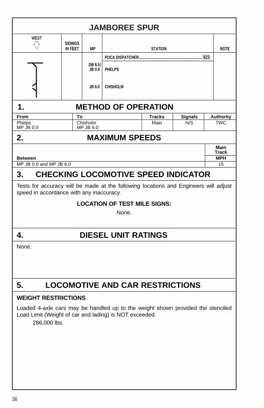
JAMBOREE SPURWEST
�� SIDINGSIN FEET MP STATION NOTE
POCA DISPATCHER.................................................................
DB 5.5/JB 0.0 PHELPS
JB 6.0 CHISHOLM
1. METHOD OF OPERATIONFrom To Tracks Signals AuthorityPhelps Chisholm Main N/S TWCMP JB 0.0 MP JB 6.0
2. MAXIMUM SPEEDSMainTrack
Between MPHMP JB 0.0 and MP JB 6.0 15
3. CHECKING LOCOMOTIVE SPEED INDICATORTests for accuracy will be made at the following locations and Engineers will adjustspeed in accordance with any inaccuracy.
LOCATION OF TEST MILE SIGNS:None.
4. DIESEL UNIT RATINGSNone.
5. LOCOMOTIVE AND CAR RESTRICTIONS
WEIGHT RESTRICTIONS
Loaded 4-axle cars may be handled up to the weight shown provided the stenciledLoad Limit (Weight of car and lading) is NOT exceeded.
286,000 lbs.
623
37
JAMBOREE SPUR
6. SWITCHES AND DERAILSNone.
7. COMMUNICATION INFORMATIONCH-6: TX = 36 RX = 36
8. DETECTOR INSTRUCTIONSNone.
9. DISTRICT INSTRUCTIONS
GENERAL INSTRUCTIONSAll train and engine employees should be on lookout for privately owned locomotiveoperating at the Chisholm Mine Operations. Crews are to contact Chisholm Mineoperators to ensure understanding of moves to be made by both crews.
Division Wide Instruction PO-L-245[1]-(1) for trains operating on heavy descendinggrades applies.
Reference NS-1 Rule A-31 concerning requirements for Two-Way End-Of-Train-Devices. The following sections of track have an average grade of 2 percent or greaterover a distance of two continuous miles, or an average grade of 1 percent or greaterover a distance of three continuous miles.
Jamboree SpurMilepost Length (Miles) Grade-Avg%JB 2.0 to JB 6.8 4.8 1.38

38
LICK FORK BRANCHWEST
�� SIDINGSIN FEET MP STATION NOTE
KENOVA DISPATCHER............................................................
N 455.3/TE 0.0 LICK FORK JCT.
TE 2.6 OLD BEN
1. METHOD OF OPERATIONFrom To Tracks Signals AuthorityLick Fork Jct. Old Ben 105MP TE 0.0 MP TE 2.6
2. MAXIMUM SPEEDSBetween MPHMP TE 0.0 and MP TE 2.6 10
3. CHECKING LOCOMOTIVE SPEED INDICATORTests for accuracy will be made at the following locations and Engineers will adjustspeed in accordance with any inaccuracy.
LOCATION OF TEST MILE SIGNS:None.
4. DIESEL UNIT RATINGSNone.
5. LOCOMOTIVE AND CAR RESTRICTIONSNone.
621
39
LICK FORK BRANCH
6. SWITCHES AND DERAILSNone.
7. COMMUNICATION INFORMATIONPocahontas Dispatcher CH-6: TX = 36 RX = 36 Code 623Kenova Dispatcher CH-2: TX = 76 RX = 76 Code 621
8. DETECTOR INSTRUCTIONSNone.
9. DISTRICT INSTRUCTIONS
GENERAL INSTRUCTIONSDivision Wide Instruction PO-L-245[1]-(1) for trains operating on heavy descendinggrades applies.
A blue derail has been installed 150 feet west of the split point derail on Lick ForkBranch Main Line at MP TE 0.2. This derail will be operated by mine personnel only.When derail is in the derailing position, train crews are not permitted to work loads.When derail is in the non-derailing position, mine personnel will not be permitted todrop cars.
Flag protection must be provided when trains or engines are operated over State Route49 Crossing, MP TE 0.1.
Reference NS-1 Rule A-31 concerning requirements for Two-Way End-Of-Train-Devices. The following sections of track have an average grade of 2 percent or greaterover a distance of two continuous miles, or an average grade of 1 percent or greaterover a distance of three continuous miles.
Lick Fork Branch is out of service from MP TE 1.52 to end of line.
Lick Fork BranchMilepost Length (Miles) Grade-Avg%TE 0.0 to TE 3.0 3.0 1.38
When delivering empties to Little Boyd, in addition to existing securement rules, threehand brakes will be placed on the east and west ends and sufficient additional brakesthroughout cars to ensure safe securement.

40
MATE CREEK BRANCHWEST
�� SIDINGSIN FEET MP STATION NOTE
KENOVA DISPATCHER............................................................
N 460.5/MC 0.0 MATE CREEK JCT.
MC 6.3 MABLEY
1. METHOD OF OPERATIONFrom To Tracks Signals AuthorityMate Creek Jct. Mabley Main N/S TWCMP MC 0.0 MP MC 6.3
2. MAXIMUM SPEEDSMainTrack
Between MPHMP MC 0.0 and MP MC 6.3 15
3. CHECKING LOCOMOTIVE SPEED INDICATORTests for accuracy will be made at the following locations and Engineers will adjustspeed in accordance with any inaccuracy.
LOCATION OF TEST MILE SIGNS:None.
4. DIESEL UNIT RATINGSNone.
5. LOCOMOTIVE AND CAR RESTRICTIONSNone.
621

41
MATE CREEK BRANCH
6. SWITCHES AND DERAILSNone.
7. COMMUNICATION INFORMATIONKenova Dispatcher CH-2: TX = 76 RX = 76 Code 621
8. DETECTOR INSTRUCTIONSNone.
9. DISTRICT INSTRUCTIONS
GENERAL INSTRUCTIONSDivision Wide Instruction PO-L-245[1]-(1) for trains operating on heavy descendinggrades applies on Track “C”.
42
ALMA BRANCHWEST
�� SIDINGSIN FEET MP STATION NOTE
KENOVA DISPATCHER............................................................
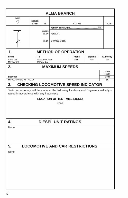
N 462.5/AL 0.0 ALMA JCT.
AL 1.6 SPROUSE CREEK
1. METHOD OF OPERATIONFrom To Tracks Signals AuthorityAlma Jct. Sprouse Creek Main N/S TWCMP AL 0.0 MP AL 1.6
2. MAXIMUM SPEEDSMainTrack
Between MPHMP AL 0.0 and MP AL 1.6 15
3. CHECKING LOCOMOTIVE SPEED INDICATORTests for accuracy will be made at the following locations and Engineers will adjustspeed in accordance with any inaccuracy.
LOCATION OF TEST MILE SIGNS:None.
4. DIESEL UNIT RATINGSNone.
5. LOCOMOTIVE AND CAR RESTRICTIONSNone.
621

43
ALMA BRANCH
6. SWITCHES AND DERAILSNone.
7. COMMUNICATION INFORMATIONKenova Dispatcher CH-2: TX = 76 RX = 76 Code 621
8. DETECTOR INSTRUCTIONSNone.
9. DISTRICT INSTRUCTIONSNS locomotives must not operate over or through the rotary dumper at Sprouse Creek,MP AL 1.8.

44
KENOVA DISTRICTWEST
�� SIDINGSIN FEET MP STATION NOTE
KENOVA DISPATCHER............................................................
N 470.3 GATE............................................................................................
N 471.3 COLLEGE ....................................................................................
N 475.6 BORDERLAND ............................................................................
N 477.6 NOLAN.........................................................................................
N 482.9 HBD-DED (Maher, WV)
N 484.3/ NAUGATUCK ............................................................................YNA 0.0
NA 3.0 PANCO......................................................................................... 1
NA 4.2 WOLF CREEK...........................................................................Y 2
NA 6.4 GREY EAGLE.............................................................................. 1
NA 6.8 HBD-DED (Grey Eagle, WV)
NA 7.4 STEPTOWN ................................................................................. 2
NA 12.4 TUNNEL 4 .................................................................................... 1
NA 16.0 TUNNEL 7 .................................................................................... 2
NA 18.2 Webb
NA 24.7 Glen Hayes
NA 27.9 HBD-DED (Columbia Coal)
NA 31.0 SEE ..............................................................................................
NA 31.7 HCD (See, WV)
NA 33.8 Fort Gay
NA 39.2 Hewlett
NA 40.1 HBD-DED (Hewlett, WV)
NA 43.5 DEAN ...........................................................................................
SCALESNA 46.5 PRICHARD...................................................................................
NA 49.1 CYRUS .........................................................................................
NA 51.1 HBD-DED (Cyrus, WV)
NA 54.1 NEAL............................................................................................
2 1
CP�
CP�
CP�
CP�
CP�
CP�
CP�
CP�
CP�
CP�
CP�
CP�
CP�
CP�
CP�
CP�
4000
LENORE
BR.
621
WOLF
CREEK
BR.
NOLAN BR.
45
KENOVA DISTRICTWEST
�� SIDINGSIN FEET MP STATION NOTE
KENOVA DISPATCHER............................................................
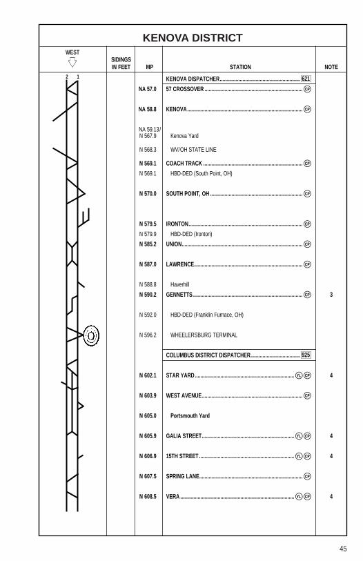
NA 57.0 57 CROSSOVER .........................................................................
NA 58.8 KENOVA......................................................................................
NA 59.13/N 567.9 Kenova Yard
N 568.3 WV/OH STATE LINE
N 569.1 COACH TRACK ..........................................................................
N 569.1 HBD-DED (South Point, OH)
N 570.0 SOUTH POINT, OH .....................................................................
N 579.5 IRONTON.....................................................................................
N 579.9 HBD-DED (Ironton)
N 585.2 UNION..........................................................................................
N 587.0 LAWRENCE.................................................................................
N 588.8 Haverhill
N 590.2 GENNETTS.................................................................................. 3
N 592.0 HBD-DED (Franklin Furnace, OH)
N 596.2 WHEELERSBURG TERMINAL
COLUMBUS DISTRICT DISPATCHER.....................................
N 602.1 STAR YARD .......................................................................... 4
N 603.9 WEST AVENUE...........................................................................
N 605.0 Portsmouth Yard
N 605.9 GALIA STREET..................................................................... 4
N 606.9 15TH STREET ....................................................................... 4
N 607.5 SPRING LANE.............................................................................
N 608.5 VERA ..................................................................................... 4
2 1
CP�
CP�
CP�
CP�
CP�
CP�
CP�
CP�
CP�
CP�
CP�
CP�
CP�
CP�
YL�
YL�
YL�
YL�
621
925

46
KENOVA DISTRICT
STATION PAGE INFORMATIONNOTE 1: Control Point eastward on Main 1 only. Control Point westward on Main 1 & 2.NOTE 2: Control Point eastward on Main 1 & 2. Control Point westward on Main 1 only.NOTE 3: Control Point eastward and westward on Main 1 only.NOTE 4: Yard Limit on Main 2 only.
1. METHOD OF OPERATIONFrom To Tracks Signals AuthorityWilliamson Signal W-4 Pull-In ABS 105MP N 470.0 Williamson YardWilliamson Vera Main 1 ABS TCMP N 470.0 MP N 608.5Williamson Star Yard Main 2 ABS TCMP N 476.0 MP N 602.1Star Yard Galia Street Main 2 ABS YLMP N 602.1 MP N 605.9Galia Street 15th Street Main 2 ABS TCMP N 605.9 MP N 606.915th Street Vera Main 2 ABS YLMP N 606.9 MP N 608.5
NOTE: All movements East of Star Yard, MP N 602.1 are controlled by the PocahontasDivision Kenova District Dispatcher.All movements West of Star Yard, MP N 602.1 are controlled by the LakeDivision Columbus District Dispatcher.Within Traffic Control limits on Main 1 between Star Yard, MP N 602.1 and GaliaStreet, and on Main 1 and Main 2 between Galia Street and 15th Street,permission must be secured from the Columbus District Dispatcher beforereversing any hand-operated switch or removing padlock from an electric lock.
2. MAXIMUM SPEEDSMainTrack
Between MPHMP N 470.0 and MP N 471.7 25MP N 471.7 and MP NA 9.5 35
Except:Scioto Pull-In Williamson 10MP N 470.4, Williamson, Through Crossover 25MP N 475.6, Borderland, Through Double Crossovers 35MP N 484.1, Naugatuck, Through Crossover at West End Middle Track 35MP NA 0.6, Through Crossover West of Naugatuck Wye 35MP NA 3.0 to MP NA 4.2, Through Turnout East End and West End Tunnel No. 1 35Wolf Creek Branch Jct., Eastward and Westward Connection Track 25MP NA 5.9, No. 1 Main Track, Curve 30MP NA 7.4, Curve 30MP NA 6.5 to MP NA 7.5, Turnouts East End and West End Tunnel No. 3 35
MP NA 9.5 and MP NA 14.8 40Except:MP NA 12.5, Turnout East End Tunnel No. 4 35
MP NA 14.8 and MP NA 22.5 35MP NA 22.5 and MP NA 40.1 40
Except:MP NA 31.0, See, Through Double Crossovers 40

47
KENOVA DISTRICT
2. MAXIMUM SPEEDS (CONT.)MainTrack
Between MPHMP NA 40.1 and MP NA 47.0 45
Except:MP NA 43.1, East Crossover 40MP NA 43.8, West Crossover 25MP NA 43.5 to MP NA 45.0, Prichard Middle Track, East Switch 25MP NA 45.0 to MP NA 46.5, Prichard Middle Track, Including West Turnout 20MP NA 44.3, No. 2 Main Track, Curve 40MP NA 46.0, Prichard, Over Weigh-in-Motion Scales (when weighing) 8MP NA 46.0, Prichard, Over Weigh-in-Motion Scales (when not weighing) 10
MP NA 47.0 and MP NA 52.0 50MP NA 52.0 and MP NA 57.7 40
Except:MP NA 57.0, East of Kenova, Through Double Crossover 40
MP NA 57.7 and MP N 569.0 30Except:All Yard Tracks Kenova Yard and Kenova Belt 15
MP N 569.0 and MP N 581.0 50Except:Trains Consisting Entirety of Piggyback (TOFC/COFC) Cars, multi-levels,
Triple Crown Trains or Stack Equipment 55MP N 570.0, South Point, Through Double Crossover 40MP N 573.8 to MP N 577.7, Curves 45MP N 577.7 to MP N 578.1, Curves 40MP N 578.1 to MP N 581.0, Curves 45
MP N 581.0 and MP N 602.1, East End Star Yard 50Except:Trains Consisting Entirety of Piggyback (TOFC/COFC) Cars, multi-levels,
Triple Crown Trains or Stack Equipment 60MP N 600.7 to MP N 602.1, Curves 45
PORTSMOUTH TERMINALMP N 602.1, East End Star Yard and MP N 605.9, Galia Street 30
Except:MP N 602.2, East End Star Yard, Through Crossover 25MP N 603.7, Through No. 1 and No. 2 Storage Tracks, Star Yard to the Dwarf Signals 25
MP N 605.7 and MP N 607.1 20MP N 607.1 and MP N 608.5, Vera 30
3. CHECKING LOCOMOTIVE SPEED INDICATORTests for accuracy will be made at the following locations and Engineers will adjustspeed in accordance with any inaccuracy.
LOCATION OF TEST MILE SIGNS:WESTWARD EASTWARDMP N 478.0 to MP N 479.0 MP N 595.0 to MP N 594.0
MP NA 56.0 to MP NA 55.0

48
KENOVA DISTRICT
4. DIESEL UNIT RATINGSDIESEL UNIT RATINGS IN TONS
Group 1 Group 2 Group 3 Group 4 Group 5 Group 6
WestwardWilliamson to Portsmouth 7500 10000 12000 14850 16500 19470
EastwardPortsmouth to Williamson 3600 4800 5750 7110 7900 9322
5. LOCOMOTIVE AND CAR RESTRICTIONS
A. WEIGHT RESTRICTIONS
Loaded 4-axle cars may be handled up to the weight shown provided the stenciledLoad Limit (Weight of car and lading) is NOT exceeded.
286,000 lbs.
B. EQUIPMENT RESTRICTIONSNS Locomotives are restricted from operating on Loop Track at Ohio River Terminal,Kenova, WV.
Six-axle units must not be operated:Aristech Plant, HaverhillMP N 567.0 — Allied Warehouse (Creasley), Kenova, WV
6. SWITCHES AND DERAILS
MAIN TRACK SWITCHES NOT EQUIPPED WITH ELECTRIC LOCKS:Hand-operated switches at the following locations are not equipped with electric locks,trains and engines must not clear on these tracks:
MP N 473.7 — Chattaroy House Track (Goodman) MP N 477.4 — Nolan HouseMP NA 14.6 — Sloan SpurMP NA 24.5 — Webb Stg. TrackMP NA 24.5 — Glenhayes House TrackMP NA 31.8 — Model DredgingMP NA 33.5 — Mill Creek SpurMP NA 33.9 — Ft. Gay House Track

49
KENOVA DISTRICT
7. COMMUNICATION INFORMATIONRADIOEmergency Code 911CYO Code 628Kenova Dispatcher CH-2: TX = 76 RX = 76 Code 621
TELEPHONECYO 7-589-5963 (Williamson) Phone: 1-800-898-4296
7-589-5994 (Kenova) Fax: 1-800-476-01477-589-5766 (Portsmouth) 1-800-589-5757
8. DETECTOR INSTRUCTIONSA restricted High Car Detector for over height cars has been installed on the KenovaDistrict at MP NA 31.7, See, WV. This detector will check eastward trains on both tracksfor over height cars only.
The detector will announce “Norfolk Southern, MP 31.7, Track #, high car from axle ###to axle ###”, when high cars are detected. ### is the first axle with a height restrictedcar and ### is the last axle with a height restricted car. The cars between axle countsmay or may not have height restricted cars. The train crew is not required to stop thetrain for inspection if their intended route does not include movement through KenovaDistrict tunnels east of See, the restricted height obstruction. If the intended route of thetrain is through the restricted obstruction, they must stop their train short of theobstruction and take whatever necessary action is required to proceed. The TrainDispatcher must be notified immediately when the crew knows they are routed throughthe obstruction and their height is restricted.
If the height detector malfunctions while a train is passing, the message, “NorfolkSouthern, MP 31.7, Track #, Detector Malfunction, call Maintainer,” will be broadcast.The train is not required to stop for inspection if their intended route does not includemovement through the restricted height obstruction. However, they must contact theTrain Dispatcher immediately to contact the Signal Department. If train is routedthrough the restriction, they must stop their train short of the obstruction and takewhatever necessary action is required to proceed.
For a train with no over height cars, the detector message will announce, “NorfolkSouthern, MP 31.7, Track #, no defects”.
This detector is for over height car detection only, and does not replace Hot BoxDetectors or their intended function. All other radio messages from Hot Box Detectorswill remain the same.

50
KENOVA DISTRICT
9. DISTRICT INSTRUCTIONS
GENERAL INSTRUCTIONSKenova District
Operation of trains, engines, and On-Track equipment EAST of the eastward homesignals at MP N 454.2 will be under the jurisdiction of the Poca Dispatcher.
Operation of trains, engines, and On-Track equipment WEST of MP N 454.2 will beunder the jurisdiction of the Kenova District Dispatcher at Bluefield, and allcommunications will be handled direct with the Kenova District Dispatcher.
A LUNAR LIGHT on the signal on Main One Track at MP N 470.5 will be used inconnection with eastward movements on Main One Track eastward onto Main TwoTrack at new crossovers.
When a diverging approach aspect is displayed on this signal and the route is lined formovement through the crossover to Main Two Track, the LUNAR LIGHT will be lighted.
When a diverging approach aspect is displayed on this signal and the route is lined formovement through the crossover to number two station track, MP N 469.8, or theMiddle Track, MP N 469.85, the LUNAR LIGHT will not be lighted.
A LUNAR LIGHT is located on the center of the bracket between existing signal mastson the westward controlled signals located at east end of Tunnel 1, approximately 4,900feet west of MP NA 2.0 will indicate as follows:
When an Approach Diverging aspect is displayed on either signal, and route islined for movement onto Eastward Main Track west of Tunnel 1, LUNAR LIGHTwill be lighted.When an Approach Diverging aspect is displayed on either signal, and LUNARLIGHT is not lighted, route will be considered to be lined for movement onto WolfCreek Branch.
A LUNAR LIGHT is located on the bracket with Signal S 401 located at MP NA 40.2,which governs westward movements on the Main Two Track. It will indicate as follows:
When an Approach diverging aspect is displayed on this signal and the route islined for movement through the crossover onto the Main One Track at Dean,MP NA 43.1, the LUNAR LIGHT will be lighted.When an Approach Diverging aspect is displayed on this signal and the route islined for movement to the Middle Track at Dean, MP NA 43.1, the LUNAR LIGHTwill not be lighted.
A LUNAR LIGHT is located on the bracket with Signal S 403 located at MP NA 40.1,which governs westward movements on the Main One Track. It will indicate as follows:
When an Approach diverging aspect is displayed on this signal and the route islined for movement through the crossover onto the Main One Track at Dean,MP NA 43.1, the LUNAR LIGHT will be lighted.When an Approach Diverging aspect is displayed on this signal and the route islined for movement to the Middle Track at Dean, MP NA 43.1, the LUNAR LIGHTwill not be lighted.
51
KENOVA DISTRICT
9. DISTRICT INSTRUCTIONS (CONT.)
GENERAL INSTRUCTIONS (CONT.)Kenova District (Cont.)
A LUNAR LIGHT is located on the bracket with Signal S 413, located at MP NA 41.3,which governs westward movement on the eastward Main Track at Hubbardstown, WVwill indicate as follows:
When an Approach Diverging aspect is displayed on this signal and the route islined for movement through the crossover onto the westward Main Track at aSignal 86L, MP NA 43.1, the LUNAR LIGHT will be lighted.When an approach diverging aspect is displayed on the same signal and theLUNAR LIGHT is not lighted, the route will be considered to be lined for movementthrough the crossover and onto Prichard Scale Track.
All employees within Kenova Yard Limits will operate on Channel #3.
When switching in Kenova Yard, no more than two car cuts can be cut off in motion atany time. Cuts of three or more cars are to be shoved to a coupling with locomotive.
Prichard Weigh-In-Motion Scales1. Trains routed through Prichard Middle Track are restricted to eight (8) MPH over
the scales while weighing; 10 MPH over the scales if not weighing.
2. Speed over Prichard Scales will be monitored and speed will be transmitted everyfive axles on Channel #1. All crews entertaining Scale Track are to monitorChannel #1 until scales are cleared.
The private grade crossing at MP NA 55.05, Neal, WV, in the vicinity of the east end ofthe Aristech Chemical facility will be cut in accordance with Operating Rule 103(d) inorder to provide emergency access routing for the industries located south of the MainTracks in this area.
In Ohio, rolling stock set off on line for storage must clear public crossings at grade byat least 500 feet.
Crews placing cars into South Point Ethanol (SPE), will physically check gate to ensurethat is properly secured prior to starting movement into plant.
Conductor of crew picking up west coal at Gennetts will furnish Portsmouth Yardmasterthe east and west car numbers of his pick up.
Do not block Upper Hayport Road Crossing at MP N 595.8, or Moore’s Road Crossing,MP N 595.2.
Do not block crossings at Cyrus while setting off or picking up. Make cuts at east end.

52
KENOVA DISTRICT
9. DISTRICT INSTRUCTIONS (CONT.)
GENERAL INSTRUCTIONS (CONT.)Dow Chemical Plant
NS Employees are “NOT” to operate any derails. If you find a derail on, you are tocontact Dow guard on duty and notify him so he can remove.
NS Employees are not to kick and/or hump any cars inside Dow Chemical Plant.
Crews are to switch lower Dow (Styron) first. After switching Styron, the Conductor willnotify guard, so he can replace derails.
Crews are not to “Build” their outbound train at Styron. After guard has replaced derailsin lower Dow (Styron), their employees will be able to return to work. Previously, theywaited until crews had completed switching in both lower and upper Dow. Crews will notbe able to go back into Styron after derails are restored.
While switching at Dow, if cars cannot be placed or pulled, the track location, time, andreason should be noted on the switch list.
If you have any questions about spotting or pulling Dow, call 4143, on inner plant phonelocated at gate.
Kenova YardPermission must be obtained from the Kenova Yardmaster before entering KenovaYard.
Normal position of switch east end Kenova Yard is lined for No. 3 and loop Track towardCSXT.
Do not pull empties from Transfer Terminal Dumping Tracks, unless first checking toascertain that the car left under shaker is uncoupled.
All doors on hopper cars must be shut and latched before pulling empties out ofTransfer Terminal. Please advise Yardmaster on duty if any cars are not shut andproperly latched.
After placing or pulling cars in Transfer Terminal, Tracks 2, 3, or 4 always line switcheson east end of Transfer for their empty Track No. 1.
Due to close clearance, do not allow units to go past the steps of loading facility at TRI-STATE REFINING (TSR), bay windows on unit will not clear walkway on TRI-STATESloading dock.
The switch off the Coach Track, which allows movement over the Diesel Track, ShopTracks, etc., must always be left lined for the Coach Track.
The Turntable and Log Track switches are to be left lined for the movement into theRound House Lead.
When switching in Kenova Yard, no more than 2 car cuts can be cut off in motion at any time.

53
KENOVA DISTRICT
9. DISTRICT INSTRUCTIONS (CONT.)
GENERAL INSTRUCTIONS (CONT.)Wheelersburg Terminal
Locomotives are not permitted to operate through the dumper.
Rotary Dumper — Wheelersburg
Dumper will no longer require the button on the exit end to be pushed before it willrotate. All concerned should expect the dumper to rotate at any time. All employees will be governed by Operating Rules and Safety and General Conduct Rules, M andGR-14, when working in the vicinity of the Rotary Dumper.
Before going on the dumper, all personnel must communicate with the dump operatorto ensure that he is aware that you are entering the dumper. The emergency stopswitch must be activated before you enter onto the dumper and reset only after allpersonnel have exited the dumper. This procedure is also necessary to shove or pullcars through the dumper, resetting the emergency switch only after movement hascleared the dumper.
NOTE: A blue light will flash on the exit end of the dumper to alert all concerned thatthe positioner is moving toward the dumper and while either the entry end or exit andelectric eyes are fouled by moving equipment or personnel.
When dumping operations are completed and the dumper is left unattended, safetychains at each end of dump must be placed across the end of the dumper andpersonnel and/or equipment will not enter onto the dumper until the emergency stopswitch is activated and the safety chains are taken down. At the completion of work,and/or train movement, safety chains will be replaced and emergency stop switch willbe reset.
Transportation employees are required to use lockout safety tags when working on therotary dumper facility at Wheelersburg Coal Terminal. The tags will be provided by theon-duty field supervisor. Upon receipt of the lockout tags, each employee working onthe dumper must print your name and sign the tag. Tags must be retained for future usein this area.
Whenever your duties require you to go on the rotary dumper (i.e., close knuckles,uncouple cars, re-spot cars for dumping, pull cars through the rotary dumper, couplecars, etc.), the following procedure will be followed:
1. If dumper operator is on duty, notify him/her of the need to tag dumper.2. Pull dumper stop button.3. Apply safety lockout tag to safety switch.4. If dumper operator is on duty, verify with him/her that dumper and positioner will
not operate.5. Once your job has been completed and you are clear of the rotary dumper, remove
tags and return safety switches to the normal (operating) position.6. If dumper operator is on duty, notify operator that you are clear of the rotary
dumper area and that equipment is setup.
All rail movements through the rotary dumper must be made at slow walking speed(2 MPH). Rail movements through the rotary dumper should only be made under thedirection of a Terminal Supervisor.

54
KENOVA DISTRICT
9. DISTRICT INSTRUCTIONS (CONT.)
GENERAL INSTRUCTIONS (CONT.)Wheelersburg Terminal (CONT.)
Employees must not go between cars on No. 1 Track Wheelersburg Terminal betweenthe Dumper and the Truck (No. 2) Crossing while Dumper is in operation.
Crews picking up or setting off cars at Wheelersburg Terminal must get permission fromeither the train crew on duty in the terminal or a terminal supervisor before lining anyswitches in the terminal. In the event that there is no one on duty at Wheelersburg, theYardmaster at Kenova will give the permission to line switches in the terminal asneeded.
ATTENTION — Remote Control Locomotives operate in this area. Locomotive cabsmay be unoccupied.
All road crews must notify switching crew, Supervisor or Train Dispatcher beforeentering Wheelersburg Terminal for information on Remote Control Unit working limits.
Portsmouth YardAll Pocahontas Division westward trains using:
Main 2 — unless otherwise instructed will stop clear of Mill Crossover Signal,MP N 603.7.
Storage Tracks No. 1 and 2 — will stop clear of dwarf signals located at the westend of these tracks, near West Avenue.
Main 1 — will stop short of East Yard Pull Out Switch, MP 603.8 near WestAvenue.
All trains will be yarded beyond these points only on instructions from the Yardmasterat East Yard or other proper authority.
The assigned direction of traffic on Storage Tracks No. 1 and 2 is westward.
Movements in the opposite directions on these tracks east of the dwarf signals locatedat MP N 603.7 must not be made without permission of the Train Dispatcher, who mustarrange for protection against opposing movements before granting such permission.
Trains arriving East Yard, West Yard, or Flat Yard should when practicable, spot thehead end of train at ground air plug.
Unless governed by signal indication, all trains and engines must approach No. 19 PullOut Switch, located on Main 1 at MP N 603.8, near West Avenue prepared to stop. Theswitch will be lined and locked as last used unless otherwise instructed and movementsapproaching it will expect to find it lined against their movement. No. 19 Pull Out Switchis a crossover switch and Rule 104(e) applies.
Westward trains approaching Portsmouth must stop short of Center Street,MP N 598.3, Wheelersburg, until authorization has been obtained from the Yardmasteron duty to proceed into Portsmouth yard.
Operating Rule 104(g) “Exception”. The following permanent “blue signal” derails areunder the exclusive control of the Mechanical Department.
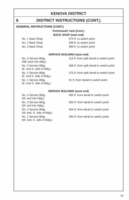
55
KENOVA DISTRICT
9. DISTRICT INSTRUCTIONS (CONT.)
GENERAL INSTRUCTIONS (CONT.)Portsmouth Yard (Cont.)BACK SHOP (east end)
No. 1 Back Shop 574 ft. to switch pointNo. 2 Back Shop 698 ft. to switch pointNo. 3 Back Shop 989 ft. to switch point
SERVICE BUILDING (east end)No. 4 Service Bldg. 114 ft. from split derail to switch point(NE track into bldg.)No. 3 Service Bldg. 368 ft. from split derail to switch point(E. end S. side of bldg.)No. 2 Service Bldg. 275 ft. from split derail to switch point(E. end S. side of bldg.)No. 1 Service Bldg. 61 ft. from derail to switch point(E. end S. side of bldg.)
SERVICE BUILDING (west end)No. 4 Service Bldg. 565 ft. from derail to switch point(W. end into bldg.)No. 3 Service Bldg. 565 ft. from derail to switch point(W. end into bldg.)No. 2 Service Bldg. 564 ft. from derail to switch point(W. end, S. side of bldg.)No. 1 Service Bldg. 295 ft. from derail to switch point(W. end, S. side of bldg.)

56
NOLAN SPURWEST
�� SIDINGSIN FEET MP STATION NOTE
KENOVA DISPATCHER............................................................
N 477.6/NH 0.0 NOLAN.........................................................................................
NH 2.5 LONG FORK JCT. ......................................................................
1. METHOD OF OPERATIONFrom To Tracks Signals AuthorityNolan Long Fork Jct. Main ABS TCMP NH 0.0 MP NH 2.5
2. MAXIMUM SPEEDSMainTrack
Between MPHMP NH 0.0 and MP NH 2.5 15MP NH 2.5 and End of Line 10
3. CHECKING LOCOMOTIVE SPEED INDICATORTests for accuracy will be made at the following locations and Engineers will adjustspeed in accordance with any inaccuracy.
LOCATION OF TEST MILE SIGNS:None.
4. DIESEL UNIT RATINGSNone.
5. LOCOMOTIVE AND CAR RESTRICTIONS
WEIGHT RESTRICTIONS
Loaded 4-axle cars may be handled up to the weight shown provided the stenciledLoad Limit (Weight of car and lading) is NOT exceeded.
286,000 lbs.
CP�
CP�
621
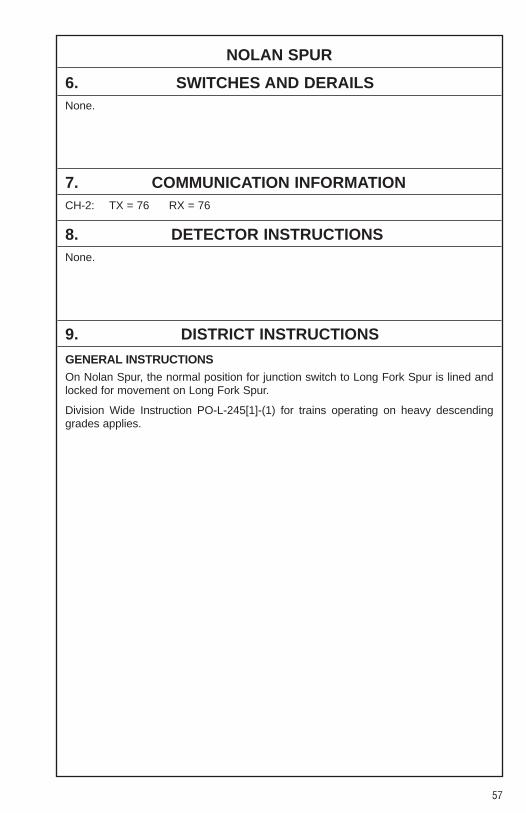
57
NOLAN SPUR
6. SWITCHES AND DERAILSNone.
7. COMMUNICATION INFORMATIONCH-2: TX = 76 RX = 76
8. DETECTOR INSTRUCTIONSNone.
9. DISTRICT INSTRUCTIONS
GENERAL INSTRUCTIONSOn Nolan Spur, the normal position for junction switch to Long Fork Spur is lined andlocked for movement on Long Fork Spur.
Division Wide Instruction PO-L-245[1]-(1) for trains operating on heavy descendinggrades applies.

58
LONG FORK SPURWEST
�� SIDINGSIN FEET MP STATION NOTE
KENOVA DISPATCHER............................................................
NH 2.5/LF 0.0 LONG FORK JCT. ......................................................................
LF 2.1 CJC ..............................................................................................
LF 3.5 DRT ..............................................................................................
LF 3.9 SIDNEY GUND JCT. ...................................................................
LF 5.8 GUND
1. METHOD OF OPERATIONFrom To Tracks Signals AuthorityLong Fork Jct. Sidney Gund Jct. Main ABS TCMP LF 0.0 MP LF 3.9Sidney Gund Jct. Gund Main N/S TWCMP LF 3.9 MP LF 5.8
2. MAXIMUM SPEEDSMainTrack
Between MPHMP LF 0.0 and MP LF 5.8 15
3. CHECKING LOCOMOTIVE SPEED INDICATORTests for accuracy will be made at the following locations and Engineers will adjustspeed in accordance with any inaccuracy.
LOCATION OF TEST MILE SIGNS:None.
4. DIESEL UNIT RATINGSNone.
5. LOCOMOTIVE AND CAR RESTRICTIONSNone.
6250
621
CP�
CP�
CP�
CP�SG SP
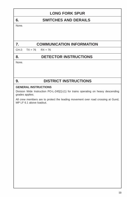
59
LONG FORK SPUR
6. SWITCHES AND DERAILSNone.
7. COMMUNICATION INFORMATIONCH-2: TX = 76 RX = 76
8. DETECTOR INSTRUCTIONSNone.
9. DISTRICT INSTRUCTIONS
GENERAL INSTRUCTIONSDivision Wide Instruction PO-L-245[1]-(1) for trains operating on heavy descendinggrades applies.
All crew members are to protect the leading movement over road crossing at Gund,MP LF 6.1 above loadout.
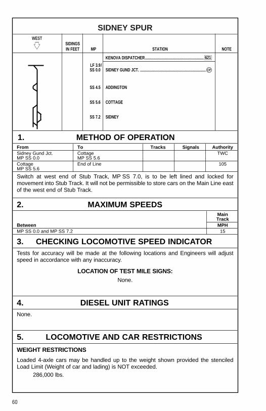
60
SIDNEY SPURWEST
�� SIDINGSIN FEET MP STATION NOTE
KENOVA DISPATCHER............................................................
LF 3.9/SS 0.0 SIDNEY GUND JCT. ...................................................................
SS 4.5 ADDINGTON
SS 5.6 COTTAGE
SS 7.2 SIDNEY
1. METHOD OF OPERATIONFrom To Tracks Signals AuthoritySidney Gund Jct. Cottage TWCMP SS 0.0 MP SS 5.6Cottage End of Line 105MP SS 5.6
Switch at west end of Stub Track, MP SS 7.0, is to be left lined and locked formovement into Stub Track. It will not be permissible to store cars on the Main Line eastof the west end of Stub Track.
2. MAXIMUM SPEEDSMainTrack
Between MPHMP SS 0.0 and MP SS 7.2 15
3. CHECKING LOCOMOTIVE SPEED INDICATORTests for accuracy will be made at the following locations and Engineers will adjustspeed in accordance with any inaccuracy.
LOCATION OF TEST MILE SIGNS:None.
4. DIESEL UNIT RATINGSNone.
5. LOCOMOTIVE AND CAR RESTRICTIONS
WEIGHT RESTRICTIONS
Loaded 4-axle cars may be handled up to the weight shown provided the stenciledLoad Limit (Weight of car and lading) is NOT exceeded.
286,000 lbs.
621
CP�
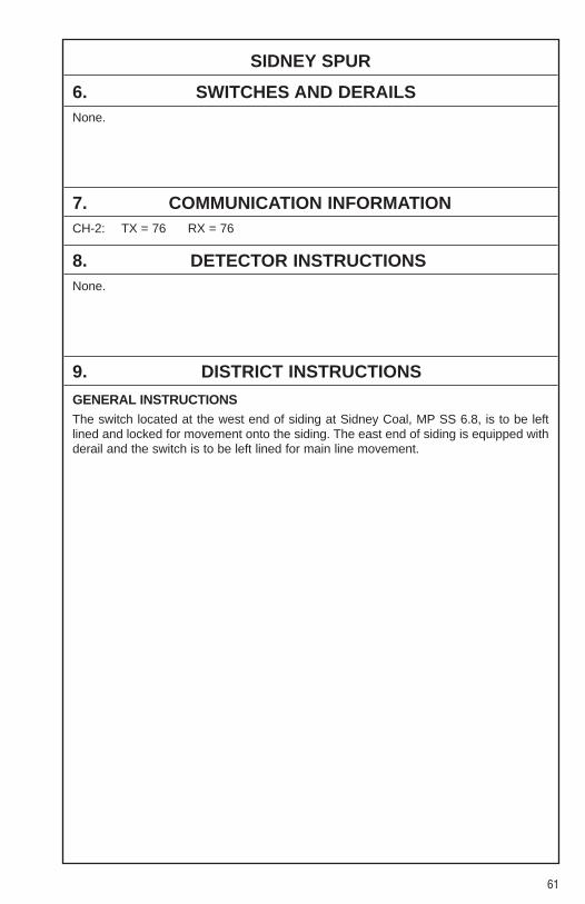
61
SIDNEY SPUR
6. SWITCHES AND DERAILSNone.
7. COMMUNICATION INFORMATIONCH-2: TX = 76 RX = 76
8. DETECTOR INSTRUCTIONSNone.
9. DISTRICT INSTRUCTIONS
GENERAL INSTRUCTIONSThe switch located at the west end of siding at Sidney Coal, MP SS 6.8, is to be leftlined and locked for movement onto the siding. The east end of siding is equipped withderail and the switch is to be left lined for main line movement.

62
LENORE BRANCHWEST
�� SIDINGSIN FEET MP STATION NOTE
KENOVA DISPATCHER............................................................
N 484.6 NAUGATUCK ............................................................................Y
N 485.6 MARROWBONE JCT. ................................................................
N 488.6/ LENOREL 0.0
L 9.8 MILLSTONE
L 15.9 SCARLETT GLEN
1. METHOD OF OPERATIONFrom To Tracks Signals AuthorityNaugatuck Marrowbone Jct. Main ABS TCMP N 484.6 MP N 485.6Marrowbone Jct. Scarlett Glen Main N/S TWCMP N 485.6 MP L 15.9
2. MAXIMUM SPEEDSMainTrack
Between MPHMP N 484.6 and MP L 15.9 15
3. CHECKING LOCOMOTIVE SPEED INDICATORTests for accuracy will be made at the following locations and Engineers will adjustspeed in accordance with any inaccuracy.
LOCATION OF TEST MILE SIGNS:None.
4. DIESEL UNIT RATINGSNone.
5. LOCOMOTIVE AND CAR RESTRICTIONSNone.
CP�
CP�
621
MBBR

63
LENORE BRANCH
6. SWITCHES AND DERAILSNone.
7. COMMUNICATION INFORMATIONCH-2: TX = 76 RX = 76
8. DETECTOR INSTRUCTIONSNone.
9. DISTRICT INSTRUCTIONS
GENERAL INSTRUCTIONSDivision Wide Instruction PO-L-245[1]-(1) for trains operating on heavy descendinggrades applies.
Reference NS-1 Rule A-31 concerning requirements for Two-Way End-Of-Train-Devices. The following sections of track have an average grade of 2 percent or greaterover a distance of two continuous miles, or an average grade of 1 percent or greaterover a distance of three continuous miles.
Lenore BranchMilepost Length (Miles) Grade-Avg%L 14.0 to L 17.8 3.8 1.22
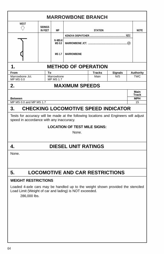
64
MARROWBONE BRANCHWEST
�� SIDINGSIN FEET MP STATION NOTE
KENOVA DISPATCHER............................................................
N 485.6/MS 0.0 MARROWBONE JCT. ................................................................
MS 1.7 MARROWBONE
1. METHOD OF OPERATIONFrom To Tracks Signals AuthorityMarrowbone Jct. Marrowbone Main N/S TWCMP MS 0.0 MP MS 1.7
2. MAXIMUM SPEEDSMainTrack
Between MPHMP MS 0.0 and MP MS 1.7 15
3. CHECKING LOCOMOTIVE SPEED INDICATORTests for accuracy will be made at the following locations and Engineers will adjustspeed in accordance with any inaccuracy.
LOCATION OF TEST MILE SIGNS:None.
4. DIESEL UNIT RATINGSNone.
5. LOCOMOTIVE AND CAR RESTRICTIONS
WEIGHT RESTRICTIONS
Loaded 4-axle cars may be handled up to the weight shown provided the stenciledLoad Limit (Weight of car and lading) is NOT exceeded.
286,000 lbs.
CP�
621

65
MARROWBONE BRANCH
6. SWITCHES AND DERAILSNone.
7. COMMUNICATION INFORMATIONCH-2: TX = 76 RX = 76
8. DETECTOR INSTRUCTIONSNone.
9. DISTRICT INSTRUCTIONS
GENERAL INSTRUCTIONSDivision Wide Instruction PO-L-245[1]-(1) for trains operating on heavy descendinggrades applies.
While working at Marrowbone, employees on the ground must not place themselvesunderneath the loadout or chute at MP MS 1.8.
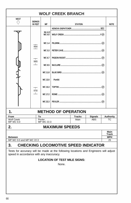
66
WOLF CREEK BRANCHWEST
�� SIDINGSIN FEET MP STATION NOTE
KENOVA DISPATCHER............................................................
NA 4.2/WC 0.0 WOLF CREEK...........................................................................Y
WC 1.4 PILGRIM.......................................................................................
WC 3.3 PETER CAVE...............................................................................
WC 6.7 PIGEON ROOST..........................................................................
WC 8.5 McCLURE ....................................................................................
WC 11.8 BLUE BIRD..................................................................................
WC 13.0 Pontiki
WC 15.3 TOPTIKI .......................................................................................
WC 17.2 ROWE ..........................................................................................
WC 22.3 PEVLER .......................................................................................
1. METHOD OF OPERATIONFrom To Tracks Signals AuthorityWolf Creek Pevler Main ABS TCMP WC 0.0 MP WC 22.3
2. MAXIMUM SPEEDSMainTrack
Between MPHMP WC 0.0 and MP WC 22.3 25
3. CHECKING LOCOMOTIVE SPEED INDICATORTests for accuracy will be made at the following locations and Engineers will adjustspeed in accordance with any inaccuracy.
LOCATION OF TEST MILE SIGNS:None.
9560
9905
9700
CP�
CP�
CP�
CP�
CP�
CP�
CP�
CP�
CP�
621
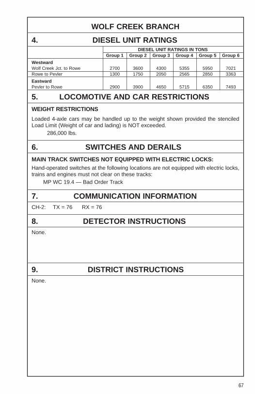
67
WOLF CREEK BRANCH
4. DIESEL UNIT RATINGSDIESEL UNIT RATINGS IN TONS
Group 1 Group 2 Group 3 Group 4 Group 5 Group 6
WestwardWolf Creek Jct. to Rowe 2700 3600 4300 5355 5950 7021Rowe to Pevler 1300 1750 2050 2565 2850 3363
EastwardPevler to Rowe 2900 3900 4650 5715 6350 7493
5. LOCOMOTIVE AND CAR RESTRICTIONS
WEIGHT RESTRICTIONS
Loaded 4-axle cars may be handled up to the weight shown provided the stenciledLoad Limit (Weight of car and lading) is NOT exceeded.
286,000 lbs.
6. SWITCHES AND DERAILS
MAIN TRACK SWITCHES NOT EQUIPPED WITH ELECTRIC LOCKS:Hand-operated switches at the following locations are not equipped with electric locks,trains and engines must not clear on these tracks:
MP WC 19.4 — Bad Order Track
7. COMMUNICATION INFORMATIONCH-2: TX = 76 RX = 76
8. DETECTOR INSTRUCTIONSNone.
9. DISTRICT INSTRUCTIONSNone.
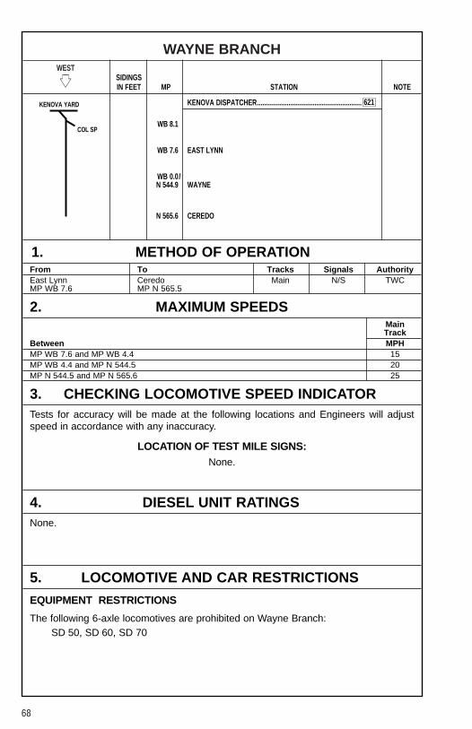
68
WAYNE BRANCHWEST
�� SIDINGSIN FEET MP STATION NOTE
KENOVA DISPATCHER............................................................
WB 8.1
WB 7.6 EAST LYNN
WB 0.0/N 544.9 WAYNE
N 565.6 CEREDO
1. METHOD OF OPERATIONFrom To Tracks Signals AuthorityEast Lynn Ceredo Main N/S TWCMP WB 7.6 MP N 565.5
2. MAXIMUM SPEEDSMainTrack
Between MPHMP WB 7.6 and MP WB 4.4 15MP WB 4.4 and MP N 544.5 20MP N 544.5 and MP N 565.6 25
3. CHECKING LOCOMOTIVE SPEED INDICATORTests for accuracy will be made at the following locations and Engineers will adjustspeed in accordance with any inaccuracy.
LOCATION OF TEST MILE SIGNS:None.
4. DIESEL UNIT RATINGSNone.
5. LOCOMOTIVE AND CAR RESTRICTIONS
EQUIPMENT RESTRICTIONS
The following 6-axle locomotives are prohibited on Wayne Branch:SD 50, SD 60, SD 70
621KENOVA YARD
COL SP
69
WAYNE BRANCH
6. SWITCHES AND DERAILSNone.
7. COMMUNICATION INFORMATIONCH-2: TX = 76 RX = 76
8. DETECTOR INSTRUCTIONSNone.
9. DISTRICT INSTRUCTIONSNone.

70
COLMONT SPURWEST
�� SIDINGSIN FEET MP STATION NOTE
KENOVA DISPATCHER............................................................
CS 3.6 COLMONT ...................................................................................
CS 1.0 ......................................................................................................
CS 0.0/ EAST LYNNWB 8.1
1. METHOD OF OPERATIONFrom To Tracks Signals AuthorityColmont Main N/S YLMP CS 3.6 MP CS 1.0
East Lynn Main N/S TWCMP CS 1.0 MP CS 0.0
2. MAXIMUM SPEEDSMainTrack
Between MPHMP CS 3.6 and MP CS 0.0 15
3. CHECKING LOCOMOTIVE SPEED INDICATORTests for accuracy will be made at the following locations and Engineers will adjustspeed in accordance with any inaccuracy.
LOCATION OF TEST MILE SIGNS:None.
4. DIESEL UNIT RATINGSNone.
5. LOCOMOTIVE AND CAR RESTRICTIONS
WEIGHT RESTRICTIONS
Loaded 4-axle cars may be handled up to the weight shown provided the stenciledLoad Limit (Weight of car and lading) is NOT exceeded.
286,000 lbs.
YL�
YL�
621
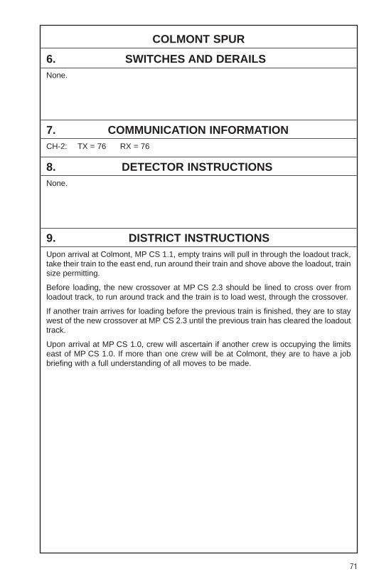
71
COLMONT SPUR
6. SWITCHES AND DERAILSNone.
7. COMMUNICATION INFORMATIONCH-2: TX = 76 RX = 76
8. DETECTOR INSTRUCTIONSNone.
9. DISTRICT INSTRUCTIONSUpon arrival at Colmont, MP CS 1.1, empty trains will pull in through the loadout track,take their train to the east end, run around their train and shove above the loadout, trainsize permitting.
Before loading, the new crossover at MP CS 2.3 should be lined to cross over fromloadout track, to run around track and the train is to load west, through the crossover.
If another train arrives for loading before the previous train is finished, they are to staywest of the new crossover at MP CS 2.3 until the previous train has cleared the loadouttrack.
Upon arrival at MP CS 1.0, crew will ascertain if another crew is occupying the limitseast of MP CS 1.0. If more than one crew will be at Colmont, they are to have a jobbriefing with a full understanding of all moves to be made.

72
CLINCH VALLEY DISTRICTWEST
�� SIDINGSIN FEET MP STATION NOTE
CLINCH VALLEY DISPATCHER ..............................................
N 366.3/CV 366.3 BLUEFIELD, VA ..........................................................................
CV 366.6 GRAHAM .....................................................................................
CV 367.6 FURNACE ....................................................................................
CV 369.2 HBD-DED (St. Clair, VA)
CV 369.8 ST. CLAIR....................................................................................
CV 371.6 SAM..............................................................................................
CV 373.1 BAILEY ........................................................................................
CV 376.0 Tip Top
CV 380.6 HBD-DED (Wittens Mill, VA)
CV 383.4 BURKS.........................................................................................
CV 385.2 TAZEWELL ..................................................................................
CV 390.0 Youngs
CV 393.3 CLIFFIELD ...................................................................................
CV 395.1 GILLESPIE...................................................................................
CV 397.0 Pounding Mill
CV 397.0 HBD-DED (Pounding Mill, VA)
CV 400.7 CEDAR BLUFF............................................................................
CV 401.2 MAIDEN .......................................................................................
CV 402.5 KENT............................................................................................
CV 404.2 RICHLANDS ..............................................................................Y
CV 404.8 Alley
CV 407.1 RAVEN .........................................................................................
CP�
CP�
CP�
CP�
CP�
CP�
CP�
CP�
CP�
CP�
CP�
CP�
CP�
CP�
CP�
4850
SS
8340
SS
8525
SS
7170
SS
9031
6500
SS
COAL CREEK
DRY FORK
BIGCREEK
625
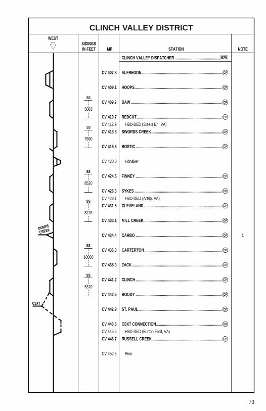
73
CLINCH VALLEY DISTRICTWEST
�� SIDINGSIN FEET MP STATION NOTE
CLINCH VALLEY DISPATCHER ..............................................
CV 407.8 ALFREDON..................................................................................
CV 409.1 HOOPS.........................................................................................
CV 409.7 DAW .............................................................................................
CV 410.7 REDCUT.......................................................................................
CV 412.9 HBD-DED (Steels Br., VA)
CV 413.8 SWORDS CREEK........................................................................
CV 415.5 BOSTIC ........................................................................................
CV 420.0 Honaker
CV 424.5 FINNEY ........................................................................................
CV 426.3 SYKES .........................................................................................
CV 428.1 HBD-DED (Artrip, VA)
CV 431.5 CLEVELAND................................................................................
CV 433.1 MILL CREEK................................................................................
CV 434.4 CARBO ........................................................................................ 1
CV 436.3 CARTERTON ...............................................................................
CV 438.0 ZACK............................................................................................
CV 441.2 CLINCH ........................................................................................
CV 442.5 BOODY ........................................................................................
CV 442.9 ST. PAUL .....................................................................................
CV 443.5 CSXT CONNECTION...................................................................
CV 445.6 HBD-DED (Burton Ford, VA)
CV 446.7 RUSSELL CREEK .......................................................................
CV 452.3 Pine
CP�
CP�
CP�
CP�
CP�
CP�
CP�
CP�
CP�
CP�
CP�
CP�
CP�
CP�
CP�
CP�
CP�
CP�
5083
SS
7690
SS
8520
SS
8276
SS
10000
SS
5310
SS
DUMPS
CREEK
CSXT
625
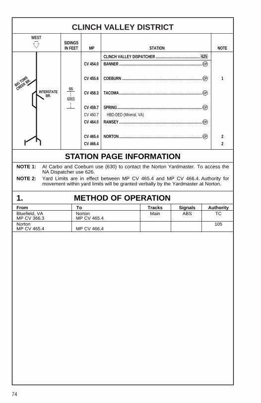
74
CLINCH VALLEY DISTRICTWEST
�� SIDINGSIN FEET MP STATION NOTE
CLINCH VALLEY DISPATCHER ..............................................
CV 454.0 BANNER ......................................................................................
CV 455.6 COEBURN ................................................................................... 1
CV 458.3 TACOMA......................................................................................
CV 459.7 SPRING........................................................................................
CV 460.7 HBD-DED (Mineral, VA)
CV 464.0 RAMSEY ......................................................................................
CV 465.4 NORTON ...................................................................................... 2
CV 466.4 2
STATION PAGE INFORMATIONNOTE 1: At Carbo and Coeburn use (630) to contact the Norton Yardmaster. To access the
NA Dispatcher use 626.NOTE 2: Yard Limits are in effect between MP CV 465.4 and MP CV 466.4. Authority for
movement within yard limits will be granted verbally by the Yardmaster at Norton.
1. METHOD OF OPERATIONFrom To Tracks Signals AuthorityBluefield, VA Norton Main ABS TCMP CV 366.3 MP CV 465.4Norton 105MP CV 465.4 MP CV 466.4
CP�
CP�
CP�
CP�
CP�
CP�
6865
SSBIG TOMS
CREEK BR.
INTERSTATEBR.
625
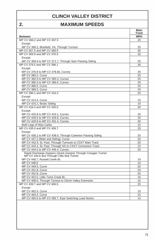
75
CLINCH VALLEY DISTRICT
2. MAXIMUM SPEEDSMainTrack
Between MPHMP CV 366.2 and MP CV 367.5 25
Except:MP CV 366.2, Bluefield, VA, Through Turnout 25
MP CV 367.5 and MP CV 369.9 30MP CV 369.9 and MP CV 376.5 35
Except:MP CV 369.9 to MP CV 371.7, Through Sam Passing Siding 25
MP CV 376.5 and MP CV 396.1 30Except:MP CV 376.8 to MP CV 378.65, Curves 25MP CV 380.2, Curve 25MP CV 382.9 to MP CV 383.3, Curves 25MP CV 386.3 to MP CV 386.6, Curves 25MP CV 389.0, Curve 25MP CV 389.3, Curve 25
MP CV 396.1 and MP CV 416.3 20Except:MP CV 414.4, Curve 15MP CV 415.1, Bostic Siding 10
MP CV 416.3 and MP CV 435.0 30Except:MP CV 420.8 to MP CV 424.1, Curves 25MP CV 428.5 to MP CV 429.9, Curves 25MP CV 429.9 to MP CV 431.4, Curves 20Both Legs of Wye Carbo 15
MP CV 435.0 and MP CV 459.7 25Except:MP CV 436.2 to MP CV 438.0, Through Carterton Passing Siding 25MP CV 437.2 (Main and Siding), Curve 20MP CV 442.9, St. Paul, Through Turnouts to CSXT Main Track 25MP CV 443.4, St. Paul, Through NS to CSXT Connection Track 15MP CV 444.5 to MP CV 446.4, Curves 20
Rapid Discharge Hoppers (Quick Dumps) Through Creagan TunnelMP CV 444.6 and Through Little Bull Tunnel
MP CV 446.7, Russell Creek Br. 10MP CV 448.6 10MP CV 449.5, Curve 20MP CV 451.8, Curve 20MP CV 452.8, Curve 20MP CV 453.5, Little Toms Creek Br. 10MP CV 458.6, Through Turnout to Clinch Valley Extension 15
MP CV 459.7 and MP CV 466.5 20Except:MP CV 462.5, Curve 15MP CV 464.4, Curve 15MP CV 465.5 to MP CV 465.7, East Switching Lead Norton 10

76
CLINCH VALLEY DISTRICT
3. CHECKING LOCOMOTIVE SPEED INDICATORTests for accuracy will be made at the following locations and Engineers will adjustspeed in accordance with any inaccuracy.
LOCATION OF TEST MILE SIGNS:WESTWARD EASTWARDMP CV 368.3 to MP CV 369.3 MP CV 457.9 to MP CV 456.9MP CV 377.0 to MP CV 378.0 MP CV 434.0 to MP CV 435.0MP CV 398.0 to MP CV 399.0 MP CV 439.0 to MP CV 438.0MP CV 411.0 to MP CV 412.0 MP CV 423.0 to MP CV 422.0MP CV 418.0 to MP CV 419.0 MP CV 378.0 to MP CV 377.0MP CV 427.5 to MP CV 426.5
4. DIESEL UNIT RATINGSDIESEL UNIT RATINGS IN TONS
Group 1 Group 2 Group 3 Group 4 Group 5 Group 6
WestwardBluefield to St. Paul 2000 2650 3200 3960 4400 5192St. Paul to Banner 1200 1600 1900 2385 2650 3127Banner to Norton 2000 2650 3200 3960 4400 5192
EastwardNorton to Finney 3300 400 5250 6525 7250 8555Finney to Richlands 1250 1700 2000 2475 2750 3245Richlands to Bluefield 1850 2500 2950 3645 4050 4783
5. LOCOMOTIVE AND CAR RESTRICTIONS
A. WEIGHT RESTRICTIONS
Loaded 4-axle cars may be handled up to the weight shown provided the stenciledLoad Limit (Weight of car and lading) is NOT exceeded.
286,000 lbs.
B. EQUIPMENT RESTRICTIONSTrailing tonnage must be limited on line segments as shown below, behind the followingequipment:1. Empty Multi-level cars.2. Empty Intermodal single-platform flats and such loaded with empty trailers or
containers.3. Empty 85-foot-long or longer flats and such flat cars when loaded with empty trailers
or containers, or loaded with only one trailer or container.4. Empty Intermodal single-axle truck flat car or such cars loaded with empty trailers or
containers.5. Empty single or multiple-unit double-stack (well) cars, or articulated single-platform
(spine) cars. Be governed by Appendix 1 in Eastern and Western Region SystemTimetables.
Maximum safe trailing tonnage behind restricted equipment between Richlands andNorton is as follows:
Eastward — 3300Westward — 2800

77
CLINCH VALLEY DISTRICT
5. LOCOMOTIVE AND CAR RESTRICTIONS (CONT.)
C. HEIGHT RESTRICTIONSBefore handling cars exceeding Plate “B” on tracks other than the Main Track orSidings, it must be determined that adequate clearance exists. Plate “C” cars and carsexceeding plate “C” dimension must not be handled between MP CV 444.0 west ofSt. Paul and MP CV 453.0 west of Little Tom Tunnel.Plate “F” cars and fully enclosed auto rack cars (exceeding plate “F” but not exceeding19'00" above top of rail) must not be handled west of Richlands.
Wreck cars of 200 tons or more capacity must not exceed a speed of 10 MPH overbridges between MP CV 449.5 and MP CV 451.0 between Russell Creek and Banner.
6. SWITCHES AND DERAILS
A. MAIN TRACK SWITCHES NOT EQUIPPED WITH ELECTRIC LOCKS:Hand-operated switches at the following locations are not equipped with electric locks,trains and engines must not clear on these tracks:
MP CV 391.1 — Maxwell SpurMP CV 417.0 — Gardner Side TrackMP CV 417.6 — Big Fork Coal Co. TrackMP CV 431.5 — Cleveland Station SidingMP CV 447.5 — Virginia City House TrackMP CV 457.6 — No. 2 Storage Track, Tacoma
B. CONTROLLED ELECTRIC LOCK SWITCHESThe unlock must be obtained from the Train Dispatcher before the following switchescan be operated:
MP CV 442.4 — Boody, West End Boody Yard
7. COMMUNICATION INFORMATIONRADIOEmergency Code 911CYO Code 628Auville Yard CH-6: TX = 36 RX = 36 Code 623CV Dispatcher CH-5: TX = 92 RX = 92 Code 625Norton Yardmaster CH-4: TX = 56 RX = 56 Code 630
TELEPHONECYO 7-589-5987 (Bluefield) Phone: 1-800-898-4296
Fax: 1-800-476-01471-800-589-5757
Enter digits 911 and your audio will be heard by the Train Dispatcher as soon as youget an answer-back tone. You may proceed with your emergency message or wait untilthe Train Dispatcher/Chief Dispatcher acknowledges your emergency call-in.
78
CLINCH VALLEY DISTRICT
8. DETECTOR INSTRUCTIONSNone.
9. DISTRICT INSTRUCTIONS
GENERAL INSTRUCTIONSDue to rusty rail conditions, all crews will flag the Brickyard crossing when working AlleyStorage.
Westward trains operating without a pusher, which have 18 or more powered Hi-Adhesion axles on line must not exceed the 7th throttle Notch between MP CV 417.0and MP CV 417.5.
When trains or equipment are to be left in Carterton Siding, the private road crossing atMP CV 437.0 will be left open. If units with or without cars are left in Carterton Siding,they will be not less than 500 feet from the Public road crossing at MP CV 436.2.
If units are to be left attached to the train, in addition to the above, the followinginstructions will apply: A ground air hose has been installed through the private crossingat MP CV 437.0. This ground air hose is equipped with self-bleeding angle cocks on bothends. The glad hands on both ends of hose are secured with a switch lock to the cross-ties. After positioning cars on either side of crossing, the cars may remain charged usingthe air hose and aligning the angle cocks correctly after air hose couplings. A note mustbe placed on the controlling unit specifying that the crossing was cut, that the crossing airhose is in use and the quantity of hand brakes tied on cars. When removing the chargedair hose, the air hose pressure must be reduced to “zero” by closing off the head endangle cock and opening the self-bleeding angle cock at the cross-ties. When removedfrom train air line, the ground air hose glad hands must be secured to the cross-ties.
When spotting loaded hopper cars at southern states, MP CV 385.4, the west hopperdoor of the loaded car to be placed must be spotted at the west end of the southernstates building (not the old depot). The cars are dropped from east to west.
When working E. Dillon, MP CV 415.7, all empty cars labeled with a “green diamond”,located near the car number, will be placed in Track #1 (closest to the loading chute)spotted east of the loading chute.
Any empties without the “green diamond” will be placed in Tracks #2, #4, or #5. Do notleave any empties fouling the east end of the Industry Tracks, reference OperatingRule 103.
Any excess empties will be placed in Swords Creek Spur.
If you have any questions, contact CV Dispatcher or Richlands Trainmaster.
Conductors on coal trains relieved between Alfredon and Bluefield are to bring tags withthem to Bluefield.
All Engineers or other crew member who either pick up and/or set off units at Richlandswill be required to call the clerk at Bluefield (4214) with the following information:
Train SymbolUnit Numbers
Track name and station where units were picked up or set off.

79
CLINCH VALLEY DISTRICT
9. DISTRICT INSTRUCTIONS (CONT.)
GENERAL INSTRUCTIONS (CONT.)Loaded cars exceeding 100 tons gross weight in blocks of 10 or more cars will behandled on the head end of trains.
Account close clearance conditions located at Wedron Silica Storage Tank, St. Paul,VA, MP CV 443.1, employees must not ride, walk, or stand on north side of East HouseTrack while equipment is moving on this track.
CSXT trains will use NS Tracks between Castlewood, MP CV 440.3 and CreaganTunnel, MP CV 444.4, under the direction of the Train Dispatcher in Bluefield. CSXTtrains will be governed by NS Operating Rules, Pocahontas Division Timetable, andTrain Dispatcher bulletin addressed to their train.
NS trains and engines may use CSXT Main Track between the North switch to CSXTBoody Siding and Waycross by authority and under the direction of the CSXT TrainDispatcher at Jacksonville. CSXT rules will govern NS trains on CSXT Track.
The provisions of Operating Rule 466 do not apply in approach to the interlockedRailroad Crossing at St. Paul.
Locomotives and cabooses must not be operated under the tipple at the followinglocations:
Tacoma Fuel.
Norton YardWhen necessary to control speed of eastward shoving movements of empty equipmentmoving through turnouts and crossovers, west end of Norton Yard, automatic brakereduction must not exceed 6 PSI unless additional air brake reduction is required tomake final stop. In addition, tractive effort must be limited to not more than 10 poweredHi-Adhesion axles or 12 conventional powered axles.
Above does not apply when movement consists entirely of loaded equipment coupledto locomotive with or without caboose on leading end.
Reference NS-1 Rule A-31 concerning requirements for Two-Way End-Of-Train-Devices. The following sections of track have an average grade of 2 percent or greaterover a distance of two continuous miles, or an average grade of 1 percent or greaterover a distance of three continuous miles.
Clinch Valley DistrictMilepost Length (Miles) Grade-Avg%CV 376.4 to CV 383.2 6.8 1.00CV 420.3 to CV 423.7 3.4 1.60CV 446.0 to CV 449.0 3.0 1.12CV 450.0 to CV 453.0 3.0 1.36
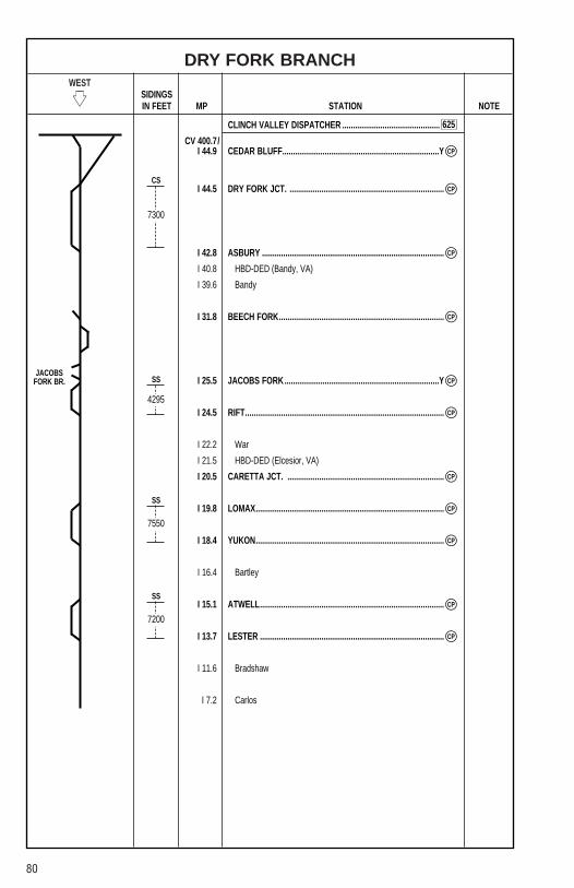
80
DRY FORK BRANCHWEST
�� SIDINGSIN FEET MP STATION NOTE
CLINCH VALLEY DISPATCHER ..............................................
CV 400.7/I 44.9 CEDAR BLUFF..........................................................................Y
I 44.5 DRY FORK JCT. .........................................................................
I 42.8 ASBURY ......................................................................................
I 40.8 HBD-DED (Bandy, VA)
I 39.6 Bandy
I 31.8 BEECH FORK..............................................................................
I 25.5 JACOBS FORK.........................................................................Y
I 24.5 RIFT..............................................................................................
I 22.2 War
I 21.5 HBD-DED (Elcesior, VA)
I 20.5 CARETTA JCT. ..........................................................................
I 19.8 LOMAX.........................................................................................
I 18.4 YUKON.........................................................................................
I 16.4 Bartley
I 15.1 ATWELL.......................................................................................
I 13.7 LESTER .......................................................................................
I 11.6 Bradshaw
I 7.2 Carlos
CP�
CP�
CP�
CP�
CP�
CP�
CP�
CP�
CP�
CP�
CP�
7300
4295
7550
7200
CS
SS
SS
SS
625
JACOBSFORK BR.
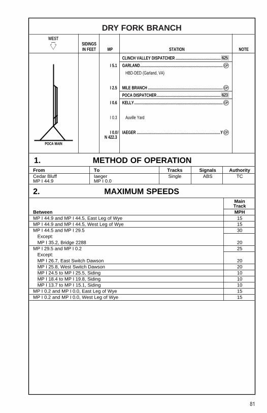
81
DRY FORK BRANCHWEST
�� SIDINGSIN FEET MP STATION NOTE
CLINCH VALLEY DISPATCHER ..............................................
I 5.1 GARLAND....................................................................................
HBD-DED (Garland, VA)
I 2.5 MILE BRANCH ............................................................................
POCA DISPATCHER.................................................................
I 0.6 KELLY..........................................................................................
I 0.3 Auville Yard
I 0.0/ IAEGER .....................................................................................YN 422.3
1. METHOD OF OPERATIONFrom To Tracks Signals AuthorityCedar Bluff Iaeger Single ABS TCMP I 44.9 MP I 0.0
2. MAXIMUM SPEEDSMainTrack
Between MPHMP I 44.9 and MP I 44.5, East Leg of Wye 15MP I 44.9 and MP I 44.5, West Leg of Wye 15MP I 44.5 and MP I 29.5 30
Except:MP I 35.2, Bridge 2288 20
MP I 29.5 and MP I 0.2 25Except:MP I 26.7, East Switch Dawson 20MP I 25.8, West Switch Dawson 20MP I 24.5 to MP I 25.5, Siding 10MP I 18.4 to MP I 19.8, Siding 10MP I 13.7 to MP I 15.1, Siding 10
MP I 0.2 and MP I 0.0, East Leg of Wye 15MP I 0.2 and MP I 0.0, West Leg of Wye 15
CP�
CP�
CP�
CP�
625
623
POCA MAIN

82
DRY FORK BRANCH
3. CHECKING LOCOMOTIVE SPEED INDICATORTests for accuracy will be made at the following locations and Engineers will adjustspeed in accordance with any inaccuracy.
LOCATION OF TEST MILE SIGNS:None.
4. DIESEL UNIT RATINGSDIESEL UNIT RATINGS IN TONS
Group 1 Group 2 Group 3 Group 4 Group 5 Group 6
WestwardCedar Bluff to Summit Tunnel 3300 4400 5250 6525 7250 8555
EastwardIaeger to Berwind, MP I 28.1 2500 3350 4000 4950 5500 6490Berwind to Summit Tunnel 1550 2100 2450 3060 3400 4012
5. LOCOMOTIVE AND CAR RESTRICTIONS
A. WEIGHT RESTRICTIONS
Loaded 4-axle cars may be handled up to the weight shown provided the stenciledLoad Limit (Weight of car and lading) is NOT exceeded.
286,000 lbs.
B. EQUIPMENT RESTRICTIONSTrailing tonnage must be limited on line segments as shown below, behind the followingequipment:1. Empty Multi-level cars.2. Empty Intermodal single-platform flats and such loaded with empty trailers or
containers.3. Empty 85-foot-long or longer flats and such flat cars when loaded with empty trailers
or containers, or loaded with only one trailer or container.4. Empty Intermodal single-axle truck flat car or such cars loaded with empty trailers or
containers.5. Empty single or multiple-unit double-stack (well) cars, or articulated single-platform
(spine) cars. Be governed by Appendix 1 in Eastern and Western Region SystemTimetables.
Maximum safe trailing tonnage behind Restricted equipment between Cedar Bluff andAuville is as follows:
Eastward — 4100Westward — 5800
C. HEIGHT RESTRICTIONSCars exceeding Plate “E” must not be handled unless specifically authorized.

83
DRY FORK BRANCH
6. SWITCHES AND DERAILS
MAIN TRACK SWITCHES NOT EQUIPPED WITH ELECTRIC LOCKS:Hand-operated switches at the following locations are not equipped with electric locks,trains and engines must not clear on these tracks:
MP I 25.0 — Rift Coal Wharf Trk., East EndMP I 25.5 — Jacobs Fork, both switches on East LegMP I 26.0 — Dawson Siding, West and East EndsMP I 38.9 — Bandy Station Sdg.
7. COMMUNICATION INFORMATIONCH-5: TX = 92 RX = 92 Cedar Bluff to Mile BranchCH-6: TX = 36 RX = 36 Mile Branch to Iaegar Yard
8. DETECTOR INSTRUCTIONSNone.
9. DISTRICT INSTRUCTIONS
GENERAL INSTRUCTIONSDiesel units must not be operated on shake-out track at Blueboy Coal Mining Corp.,Beartown, MP I 7.9.
Reference NS-1 Rule A-31 concerning requirements for Two-Way End-Of-Train-Devices. The following sections of track have an average grade of 2 percent or greaterover a distance of two continuous miles, or an average grade of 1 percent or greaterover a distance of three continuous miles.
Dry Fork BranchMilepost Length (Miles) Grade-Avg%I 30.0 to I 38.0 8.0 1.35
Beech Fork SpurDivision Wide Instruction PO-L-245[1]-(1) for trains operating on heavy descendinggrades applies.
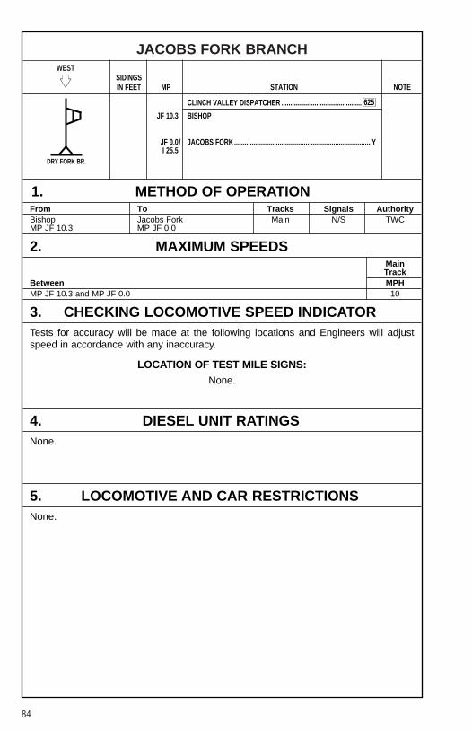
84
JACOBS FORK BRANCHWEST
�� SIDINGSIN FEET MP STATION NOTE
CLINCH VALLEY DISPATCHER ..............................................
JF 10.3 BISHOP
JF 0.0/ JACOBS FORK ...............................................................................YI 25.5
1. METHOD OF OPERATIONFrom To Tracks Signals AuthorityBishop Jacobs Fork Main N/S TWCMP JF 10.3 MP JF 0.0
2. MAXIMUM SPEEDSMainTrack
Between MPHMP JF 10.3 and MP JF 0.0 10
3. CHECKING LOCOMOTIVE SPEED INDICATORTests for accuracy will be made at the following locations and Engineers will adjustspeed in accordance with any inaccuracy.
LOCATION OF TEST MILE SIGNS:None.
4. DIESEL UNIT RATINGSNone.
5. LOCOMOTIVE AND CAR RESTRICTIONSNone.
625
DRY FORK BR.

85
JACOBS FORK BRANCH
6. SWITCHES AND DERAILSNone.
7. COMMUNICATION INFORMATIONCH-5: TX = 92 RX = 92
8. DETECTOR INSTRUCTIONSNone.
9. DISTRICT INSTRUCTIONS
GENERAL INSTRUCTIONSHighway crossings requiring flag protection when trains or engines are operated oversuch crossings:
Mile Post State RouteBranch Line Location NumberJacobs Fork Branch JF 6.0 + 1639 ft. St. Rt. 16Jacobs Fork Branch JF 3.0 + 5272 ft. St. Rt. 16Jacobs Fork Branch JF 10.0 + 237.5 ft. St. Rt. 16

86
BIG CREEK BRANCHWEST
�� SIDINGSIN FEET MP STATION NOTE
CLINCH VALLEY DISPATCHER ..............................................
CV 404.2/R 0.0 RICHLANDS............................................................................. Y 1
R 1.3 CITY LIMITS.................................................................................
R 3.4 SEABOARD .................................................................................
R 5.5 LARK............................................................................................
R 7.2 JEWELL .......................................................................................
R 8.2 BLAIR...........................................................................................
R 14.8/ WYATT......................................................................................... 2
DC 16.1
STATION PAGE INFORMATIONNOTE 1: CP eastward only.NOTE 2: Richlands to Wyatt communication controlled by Clinch Valley Dispatcher, and move-
ments west of Wyatt controlled by PD Dispatcher.
1. METHOD OF OPERATIONFrom To Tracks Signals AuthorityRichlands Wyatt Main ABS TCMP R 0.0 MP R 14.8
2. MAXIMUM SPEEDSMainTrack
Between MPHMP R 0.0 and MP R 0.1, East Leg Wye 15MP R 0.0 and MP R 0.1, West Leg Wye 10MP R 0.1 and MP R 14.8 20
3. CHECKING LOCOMOTIVE SPEED INDICATORTests for accuracy will be made at the following locations and Engineers will adjustspeed in accordance with any inaccuracy.
LOCATION OF TEST MILE SIGNS:None.
8966
625
CP�
CP�
CP�
CP�
CP�
CP�
CP�
CLINCH VAL.
CS
DISMAL CREEK
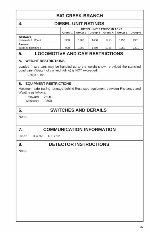
87
BIG CREEK BRANCH
4. DIESEL UNIT RATINGSDIESEL UNIT RATINGS IN TONS
Group 1 Group 2 Group 3 Group 4 Group 5 Group 6
WestwardRichlands to Wyatt 900 1200 1450 1755 1950 2301
EastwardWyatt to Richlands 900 1200 1450 1755 1950 2301
5. LOCOMOTIVE AND CAR RESTRICTIONS
A. WEIGHT RESTRICTIONS
Loaded 4-axle cars may be handled up to the weight shown provided the stenciledLoad Limit (Weight of car and lading) is NOT exceeded.
286,000 lbs.
B. EQUIPMENT RESTRICTIONSMaximum safe trailing tonnage behind Restricted equipment between Richlands andWyatt is as follows:
Eastward — 2500Westward — 2500
6. SWITCHES AND DERAILSNone.
7. COMMUNICATION INFORMATIONCH-5: TX = 92 RX = 92
8. DETECTOR INSTRUCTIONSNone.

88
BIG CREEK BRANCH
9. DISTRICT INSTRUCTIONS
GENERAL INSTRUCTIONSDivision Wide Instruction PO-L-245[1]-(1) for trains operating on heavy descendinggrades applies.
When empties are set off at Big Creek Tiller Mine, MP R 6.8, Big Creek Branch, carsleft standing will be secured with at least a hand brake applied on every other car.
Westward empty trains on Big Creek Branch, Wyatt Cut Off, being assisted by a pushernot equipped with a cut-on-the-fly device, will stop head end of train at Blair Signal whilepusher uncouples.
Employees must not ride on the outside of equipment through Blair Tunnel, MP R 7.2to MP R 7.8, account the possibility of falling rocks.
Reference NS-1 Rule A-31 concerning requirements for Two-Way End-Of-Train-Devices. The following sections of track have an average grade of 2 percent or greaterover a distance of two continuous miles, or an average grade of 1 percent or greaterover a distance of three continuous miles.
Big Creek BranchMilepost Length (Miles) Grade-Avg%R 1.2 to R 7.1 5.9 1.50R 7.1 to R 15.1 8.0 1.87
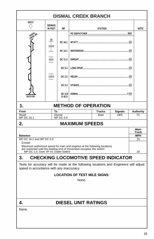
89
DISMAL CREEK BRANCHWEST
�� SIDINGSIN FEET MP STATION NOTE
PD DISPATCHER ......................................................................
DC 16.1 WYATT.........................................................................................
DC 14.1 WHITEWOOD ..............................................................................
DC 11.3 DWIGHT .......................................................................................
DC 5.4 LONG SPUR ................................................................................
DC 2.5 HELEN .........................................................................................
DC 0.3 STOKES.......................................................................................
DC 0.0/ DISMAL .....................................................................................YD 42.5
1. METHOD OF OPERATIONFrom To Tracks Signals AuthorityWyatt Dismal Main ABS TCMP DC 16.1 MP DC 0.0
2. MAXIMUM SPEEDSMainTrack
Between MPHMP DC 16.2 and MP DC 0.0 25
Except:Maximum authorized speed for train and engines at the following locationsare restricted until the leading end of movement occupies the switch:
MP DC 1.0, Over VP #1 Outlet Switch 20
3. CHECKING LOCOMOTIVE SPEED INDICATORTests for accuracy will be made at the following locations and Engineers will adjustspeed in accordance with any inaccuracy.
LOCATION OF TEST MILE SIGNS:None.
4. DIESEL UNIT RATINGSNone.
10600
8600
10600
624
CP�
CP�
CP�
CP�
CP�
CP�
CP�
DISMAL
CREEK BR.
BUCH BR.
CS

90
DISMAL CREEK BRANCH
5. LOCOMOTIVE AND CAR RESTRICTIONS
A. WEIGHT RESTRICTIONS
Loaded 4-axle cars may be handled up to the weight shown provided the stenciledLoad Limit (Weight of car and lading) is NOT exceeded.
286,000 lbs.
B. EQUIPMENT RESTRICTIONSMaximum safe trailing tonnage behind Restricted equipment between Wyatt andDismal is as follows:
Eastward — 2500Westward — 2500
6. SWITCHES AND DERAILSNone.
7. COMMUNICATION INFORMATIONCH-3: TX = 22 RX = 22
8. DETECTOR INSTRUCTIONSNone.
9. DISTRICT INSTRUCTIONS
GENERAL INSTRUCTIONSThe westward signal at MP DC 16.3 in approach to Wyatt is an inoperative approachsignal and does not afford automatic block protection.
The eastward and westward signals at Dwight, VA, MP DC 11.3, governing movementto and from Spruce Pine Branch are out of service account Rusty Rail. Operating Rule249 is in effect.
Division Wide Instruction PO-L-245[1]-(1) for trains operating on heavy descendinggrades applies.
Close clearance exist at the following locations:MP DC 0.3 — Jewell Smokeless No. 2 Outlet Track

91
COAL CREEK BRANCHWEST
�� SIDINGSIN FEET MP STATION NOTE
CLINCH VALLEY DISPATCHER ..............................................
CV 407.1/RG 0.0 RAVEN
RG 2.8 NEW GARDEN
1. METHOD OF OPERATIONFrom To Tracks Signals AuthorityRaven New Garden Main N/S TWCMP RG 0.0 MP RG 2.8
2. MAXIMUM SPEEDSMainTrack
Between MPHMP RG 0.0 and MP RG 2.8 15
3. CHECKING LOCOMOTIVE SPEED INDICATORTests for accuracy will be made at the following locations and Engineers will adjustspeed in accordance with any inaccuracy.
LOCATION OF TEST MILE SIGNS:None.
4. DIESEL UNIT RATINGSNone.
5. LOCOMOTIVE AND CAR RESTRICTIONSNone.
625CV MAIN

92
COAL CREEK BRANCH
6. SWITCHES AND DERAILSNone.
7. COMMUNICATION INFORMATIONCH-5: TX = 92 RX = 92
8. DETECTOR INSTRUCTIONSNone.
9. DISTRICT INSTRUCTIONS
GENERAL INSTRUCTIONSWhen not protecting unattended equipment, the switch point derail on the main line,MP RG 2.2, may be left in the non-derailing position and the switch at the west end ofNew Garden Storage, MP RG 2.8, may be left lined for the main line.
When protecting unattended equipment, the Main Line switch at the west end of NewGarden Storage, MP RG 2.8, will be lined for the storage track and the switch pointderail on the east end of New Garden Storage Track, MP RG 2.25, will be left in thederailing position. The switch point derail on the Main Line, MP RG 2.2, may be left linedin the non-derailing position. Trains and engines approaching these locations mustexpect to find a switch or derail lined against the movement.
No more than 60 cars may be shoved on Coal Creek Branch without approval from theTrainmaster at Richlands.
Division Wide Instruction PO-L-245[1]-(1) for trains operating on heavy descendinggrades applies.
Reference NS-1 Rule A-31 concerning requirements for Two-Way End-Of-Train-Devices. The following sections of track have an average grade of 2 percent or greaterover a distance of two continuous miles, or an average grade of 1 percent or greaterover a distance of three continuous miles.
Coal Creek BranchMilepost Length (Miles) Grade-Avg%RG 0.0 to RG 2.8 2.8 1.69
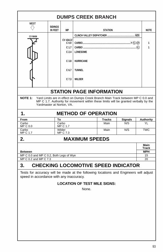
93
DUMPS CREEK BRANCHWEST
�� SIDINGSIN FEET MP STATION NOTE
CLINCH VALLEY DISPATCHER ..............................................
CV 434.3/C 0.0 CARBO................................................................................Y 1
C 1.7 CARBO ........................................................................................ 1
C 2.4 LONESOME
C 3.8 HURRICANE
C 6.7 TUNNEL
C 7.3 WILDER
STATION PAGE INFORMATIONNOTE 1: Yard Limits are in effect on Dumps Creek Branch Main Track between MP C 0.0 and
MP C 1.7. Authority for movement within these limits will be granted verbally by theYardmaster at Norton, VA.
1. METHOD OF OPERATIONFrom To Tracks Signals AuthorityCarbo Carbo Main N/S YLMP C 0.0 MP C 1.7Carbo Wilder Main N/S TWCMP C 1.7 MP C 7.3
2. MAXIMUM SPEEDSMainTrack
Between MPHMP C 0.0 and MP C 0.2, Both Legs of Wye 15MP C 0.2 and MP C 7.3 20
3. CHECKING LOCOMOTIVE SPEED INDICATORTests for accuracy will be made at the following locations and Engineers will adjustspeed in accordance with any inaccuracy.
LOCATION OF TEST MILE SIGNS:None.
YL�
YL�
625
CP�
CV MAIN

94
DUMPS CREEK BRANCH
4. DIESEL UNIT RATINGSDIESEL UNIT RATINGS IN TONS
Group 1 Group 2 Group 3 Group 4 Group 5 Group 6
WestwardCarbo to Lonesome 3600 4800 5400 6480 7200 8496Lonesome to Hurricane 1330 1775 2000 2400 2660 3138Hurricane to Wilder 740 990 1100 1330 1480 1746
5. LOCOMOTIVE AND CAR RESTRICTIONSNone.
6. SWITCHES AND DERAILSNone.
7. COMMUNICATION INFORMATIONCV Dispatcher CH-5: TX = 92 RX = 92 Code 625Norton Yardmaster CH-4: TX = 56 RX = 56 Code 630
8. DETECTOR INSTRUCTIONSNone.
9. DISTRICT INSTRUCTIONS
GENERAL INSTRUCTIONSDivision Wide Instruction PO-L-245[1]-(1) for trains operating on heavy descendinggrades applies.
Loaded cars exceeding 100 tons gross weight in blocks of 10 or more cars will behandled on the head end of trains.
The following procedure will govern crews using Clinchfield Coal Co. Tracks at theMoss No. 3 Cleaning Plant at Carbo, VA.
LOWER YARD — Crews switching in the Lower Yard will use the Lower Yard SwitchProtection Control Panel and be governed by the instructions thereon.

95
DUMPS CREEK BRANCH
9. DISTRICT INSTRUCTIONS (CONT.)
GENERAL INSTRUCTIONS (CONT.)1. R.R. Crew — Notify CCC Lower Car Dropper to position switches to tracks to leave
“In Service”. Green lights indicate switch alignment. (See Note).
2. R.R. Crew — Turn appropriate selector switch to “Out Service”. Red lights will flashon selector switch.
3. R.R. Crew — Service Yard. Only enter those tracks which have been blocked “Outof Service”.
4. R.R. Crew — Notify CCC Lower Car Dropper when service is complete. (SeeNote).
5. R.R. Crew — Turn ALL Selector Switches to “In Service”.
NOTE: CCC Lower Car Dropper may be contacted using talk-back telephone located above TagBox adjacent to Lower Yard Track No. 1. If unable to contact CCC Lower Car Dropper bytalk-back telephone, a member of the crew must proceed to the loadout area located justwest of the west end of Lower Yard and (1) talk personally with CCC Lower Car Dropper,or (2) determine that Moss #3 employees are not loading coal before entering any trackin Lower Yard.
Whenever cars are tailed out over the power switches at the West End of the LowerYard, Conductors will check the Control Board to assure proper switch alignment andwill take all switches in the route “Out Service” before the move is made. An employeewill be stationed to observe the movement over the switches.
RAW COAL YARD — When the plant is working, Conductors will contact the Engineerof the Moss No. 3 Switch Crew and will arrange for protection before placing cars intothe “Raw Coal Yard”.
Due to close clearance, employees must not ride sides of cars between Tracks 4 and5, or 5 and 6, east end, first curve, MP C 3.2, Moss No. 3 Raw Coal Yard.
Empty car(s) must not be mixed within a train consist containing ten (10) or moreloaded cars, or handled between locomotives and ten (10) or more loaded cars whenshoving into American Electric Power Plant at Carbo, VA, MP C 0.2.
Close clearance exists at gates entering American Electric Power Plant at Carbo,MP C 0.2.
Close clearance exists between Dumps Creek Main Line and Lonesome Storagebetween MP C 1.8 and MP C 3.0.
Locomotive and cabooses must not be operated under the tipple at the followinglocations:
Banner DockMoss #3 Cleaning PlantWilder Dock
Reference NS-1 Rule A-31 concerning requirements for Two-Way End-Of-Train-Devices. The following sections of track have an average grade of 2 percent or greaterover a distance of two continuous miles, or an average grade of 1 percent or greaterover a distance of three continuous miles.
Dumps Creek BranchMilepost Length (Miles) Grade-Avg%C 3.0 to C 7.3 4.5 1.63

96
BIG TOMS CREEK BRANCHWEST
�� SIDINGSIN FEET MP STATION NOTE
CLINCH VALLEY DISPATCHER ..............................................
CV 455.6/BT 0.0 COEBURN
BT 0.5 FEED MILL
BT 0.9 BALL PARK
1. METHOD OF OPERATIONFrom To Tracks Signals AuthorityCoeburn Ball Park Main N/S TWCMP BT 0.0 MP BT 0.9
2. MAXIMUM SPEEDSMainTrack
Between MPHMP BT 0.0 and MP BT 0.9 15
3. CHECKING LOCOMOTIVE SPEED INDICATORTests for accuracy will be made at the following locations and Engineers will adjustspeed in accordance with any inaccuracy.
LOCATION OF TEST MILE SIGNS:None.
4. DIESEL UNIT RATINGSNone.
625CV MAIN

97
BIG TOMS CREEK BRANCH
5. LOCOMOTIVE AND CAR RESTRICTIONSNone.
6. SWITCHES AND DERAILSNone.
7. COMMUNICATION INFORMATIONCV Dispatcher CH-5: TX = 92 RX = 92 Code 625Norton Yardmaster CH-4: TX = 56 RX = 56 Code 630
8. DETECTOR INSTRUCTIONSNone.
9. DISTRICT INSTRUCTIONS
GENERAL INSTRUCTIONSLoaded cars exceeding 100 tons gross weight in blocks of 10 or more cars will behandled on the head end of trains.
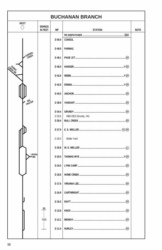
98
BUCHANAN BRANCHWEST
�� SIDINGSIN FEET MP STATION NOTE
PD DISPATCHER ......................................................................
D 50.6 CONSOL
D 49.5 PARMAC
D 48.1 PAGE JCT....................................................................................
D 46.5 HANGER....................................................................................Y
D 42.6 WEBB ........................................................................................Y
D 42.5 DISMAL .....................................................................................Y
D 40.5 ANCHOR......................................................................................
D 38.9 VANSANT ....................................................................................
D 34.4 GRUNDY ......................................................................................
D 33.6 HBD-DED (Grundy, VA)
D 28.4 BULL CREEK ..............................................................................
D 27.9 E. E. WELLER.......................................................................
D 26.0 Weller Yard
D 25.8 W. E. WELLER ............................................................................
D 25.0 THOMAS WYE ..........................................................................Y
D 24.0 LYNN CAMP ................................................................................
D 18.5 HOME CREEK .............................................................................
D 17.6 VIRGINIA LEE..............................................................................
D 16.9 CARTWRIGHT .............................................................................
D 16.3 RAITT ...........................................................................................
D 12.8 KNOX ...........................................................................................
D 12.1 MIDWAY.......................................................................................
D 11.4 HURLEY.......................................................................................
YL�
7620
CP�
CP�
CP�
CP�
CP�
CP�
CP�
CP�
CP�
CP�
CP�
CP�
CP�
CP�
CP�
CP�
YL�
CP�
CP�
GARDEN
CREEK
BIG
PRATER
LEVISABR.
SS
624
DISMALCREEK BR.
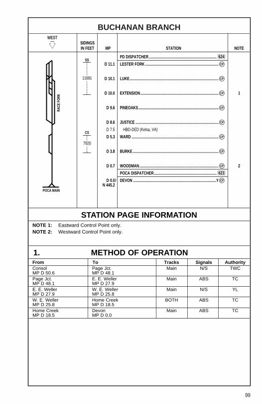
99
BUCHANAN BRANCHWEST
�� SIDINGSIN FEET MP STATION NOTE
PD DISPATCHER ......................................................................
D 11.1 LESTER FORK ............................................................................
D 10.1 LUKE............................................................................................
D 10.0 EXTENSION................................................................................. 1
D 9.6 PINEOAKS...................................................................................
D 8.6 JUSTICE ......................................................................................
D 7.5 HBD-DED (Kelsa, VA)
D 5.3 WARD ..........................................................................................
D 3.8 BURKE.........................................................................................
D 0.7 WOODMAN.................................................................................. 2
POCA DISPATCHER.................................................................
D 0.0/ DEVON ......................................................................................YN 445.2
STATION PAGE INFORMATIONNOTE 1: Eastward Control Point only.NOTE 2: Westward Control Point only.
1. METHOD OF OPERATIONFrom To Tracks Signals AuthorityConsol Page Jct. Main N/S TWCMP D 50.6 MP D 48.1Page Jct. E. E. Weller Main ABS TCMP D 48.1 MP D 27.9E. E. Weller W. E. Weller Main N/S YLMP D 27.9 MP D 25.8W. E. Weller Home Creek BOTH ABS TCMP D 25.8 MP D 18.5Home Creek Devon Main ABS TCMP D 18.5 MP D 0.0
11691
7920
CP�
CP�
CP�
CP�
CP�
CP�
CP�
CP�
CP�
624
623
RACE
FORK
POCA MAIN
CS
SS

100
BUCHANAN BRANCH
2. MAXIMUM SPEEDSMainTrack
Between MPHMP D 50.6 and MP D 27.9 25
Except:MP D 46.5, Both Legs of Wye 15MP D 46.5, Hanger Spur 15MP D 42.5, Both Legs of Wye 15MP D 28.4, Bull Creek Spur 15
MP D 27.9 and MP D 25.0 20MP D 25.0 and MP D 0.0 25
Except:MP D 18.5, Through Turnout 25MP D 3.8, Upper Elk Creek Br. 10MP D 0.0, Both Legs of Wye 15
Maximum authorized speed for trains and engines at the following locations are restricted until the leading end of movement occupies the switch:
MP D 40.8, Dismal and MP D 41.3, Over Engine Track Switches 20MP D 41.4, Over Coke Plant Outlet Switch 20
3. CHECKING LOCOMOTIVE SPEED INDICATORTests for accuracy will be made at the following locations and Engineers will adjustspeed in accordance with any inaccuracy.
LOCATION OF TEST MILE SIGNS:WESTWARD EASTWARDMP D 31.0 to MP D 30.0 MP D 22.7 to MP D 23.7MP D 23.7 to MP D 22.7 MP D 30.0 to MP D 31.0
4. DIESEL UNIT RATINGSDIESEL UNIT RATINGS IN TONS
Group 1 Group 2 Group 3 Group 4 Group 5 Group 6
WestwardThomas to Raitt 1300 1750 2050 2565 2850 3363
EastwardHurley to Raitt 1100 1500 1750 2160 2400 2832
5. LOCOMOTIVE AND CAR RESTRICTIONS
A. WEIGHT RESTRICTIONS
Loaded 4-axle cars may be handled up to the weight shown provided the stenciledLoad Limit (Weight of car and lading) is NOT exceeded.
286,000 lbs.

101
BUCHANAN BRANCH
5. LOCOMOTIVE AND CAR RESTRICTIONS (CONT.)
B. EQUIPMENT RESTRICTIONSTrailing tonnage must be limited on line segments as shown below, behind the followingequipment:1. Empty Multi-level cars.2. Empty Intermodal single-platform flats and such loaded with empty trailers or
containers.3. Empty 85-foot-long or longer flats and such flat cars when loaded with empty trailers
or containers, or loaded with only one trailer or container.4. Empty Intermodal single-axle truck flat car or such cars loaded with empty trailers or
containers.5. Empty single or multiple-unit double-stack (well) cars, or articulated single-platform
(spine) cars. Be governed by Appendix 1 in Eastern and Western Region SystemTimetables.
Maximum safe trailing tonnage behind Restricted equipment between Weller andRichlands is as follows:
Eastward — 2500Westward — 2500
6. SWITCHES AND DERAILS
MAIN TRACK SWITCHES NOT EQUIPPED WITH ELECTRIC LOCKS:Hand-operated switches at the following locations are not equipped with electric locks,trains and engines must not clear on these tracks:
MP D 0.9 — WoodmanMP D 10.1 — Lester Coal (Kelsa No. 2)MP D 23.0 — BelibeMP N 24.8 — Bear No. 1, DeliveryMP N 29.4 — Wellmore No. 4 (Primrose)MP D 30.2 — Blue Watch No. 2 (Tiny)MP D 33.9 — Wellmore No. 1 (Grundy Fuel)MP D 37.1 — Edith FayMP D 37.4, MP D 37.8 — Tookland
7. COMMUNICATION INFORMATIONRADIO
Emergency Code 911CYO Code 628PD Dispatcher CH-3: TX = 22 RX = 22 Code 624
TELEPHONECYO 7-589-5949 Phone: 1-800-898-4296
Fax: 1-800-476-01471-800-589-5757
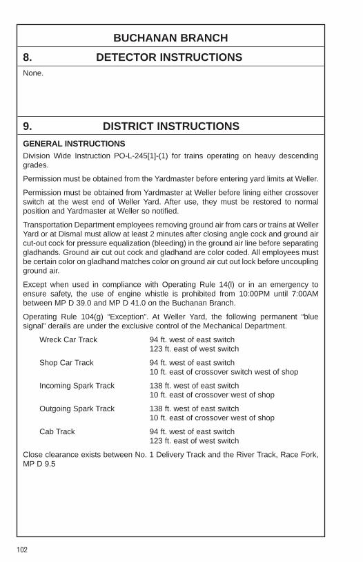
102
BUCHANAN BRANCH
8. DETECTOR INSTRUCTIONSNone.
9. DISTRICT INSTRUCTIONS
GENERAL INSTRUCTIONSDivision Wide Instruction PO-L-245[1]-(1) for trains operating on heavy descendinggrades.
Permission must be obtained from the Yardmaster before entering yard limits at Weller.
Permission must be obtained from Yardmaster at Weller before lining either crossoverswitch at the west end of Weller Yard. After use, they must be restored to normalposition and Yardmaster at Weller so notified.
Transportation Department employees removing ground air from cars or trains at WellerYard or at Dismal must allow at least 2 minutes after closing angle cock and ground aircut-out cock for pressure equalization (bleeding) in the ground air line before separatinggladhands. Ground air cut out cock and gladhand are color coded. All employees mustbe certain color on gladhand matches color on ground air cut out lock before uncouplingground air.
Except when used in compliance with Operating Rule 14(l) or in an emergency toensure safety, the use of engine whistle is prohibited from 10:00PM until 7:00AMbetween MP D 39.0 and MP D 41.0 on the Buchanan Branch.
Operating Rule 104(g) “Exception”. At Weller Yard, the following permanent “bluesignal” derails are under the exclusive control of the Mechanical Department.
Wreck Car Track 94 ft. west of east switch123 ft. east of west switch
Shop Car Track 94 ft. west of east switch10 ft. east of crossover switch west of shop
Incoming Spark Track 138 ft. west of east switch10 ft. east of crossover west of shop
Outgoing Spark Track 138 ft. west of east switch10 ft. east of crossover west of shop
Cab Track 94 ft. west of east switch123 ft. east of west switch
Close clearance exists between No. 1 Delivery Track and the River Track, Race Fork,MP D 9.5
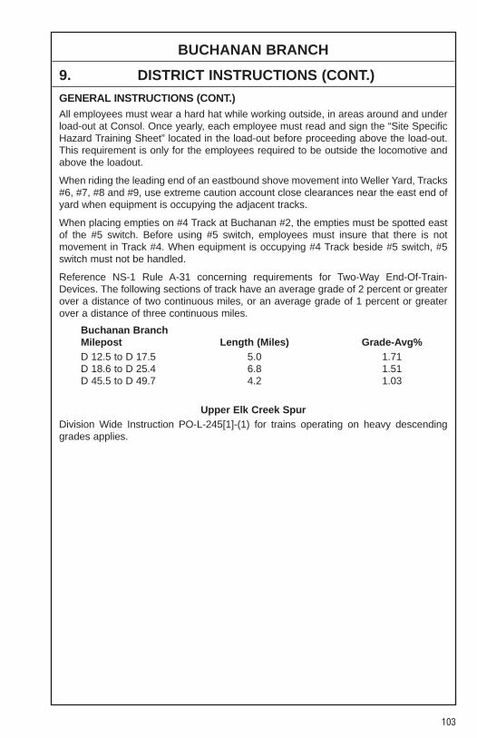
103
BUCHANAN BRANCH
9. DISTRICT INSTRUCTIONS (CONT.)
GENERAL INSTRUCTIONS (CONT.)All employees must wear a hard hat while working outside, in areas around and underload-out at Consol. Once yearly, each employee must read and sign the “Site SpecificHazard Training Sheet” located in the load-out before proceeding above the load-out.This requirement is only for the employees required to be outside the locomotive andabove the loadout.
When riding the leading end of an eastbound shove movement into Weller Yard, Tracks#6, #7, #8 and #9, use extreme caution account close clearances near the east end ofyard when equipment is occupying the adjacent tracks.
When placing empties on #4 Track at Buchanan #2, the empties must be spotted eastof the #5 switch. Before using #5 switch, employees must insure that there is notmovement in Track #4. When equipment is occupying #4 Track beside #5 switch, #5switch must not be handled.
Reference NS-1 Rule A-31 concerning requirements for Two-Way End-Of-Train-Devices. The following sections of track have an average grade of 2 percent or greaterover a distance of two continuous miles, or an average grade of 1 percent or greaterover a distance of three continuous miles.
Buchanan BranchMilepost Length (Miles) Grade-Avg%D 12.5 to D 17.5 5.0 1.71D 18.6 to D 25.4 6.8 1.51D 45.5 to D 49.7 4.2 1.03
Upper Elk Creek SpurDivision Wide Instruction PO-L-245[1]-(1) for trains operating on heavy descendinggrades applies.
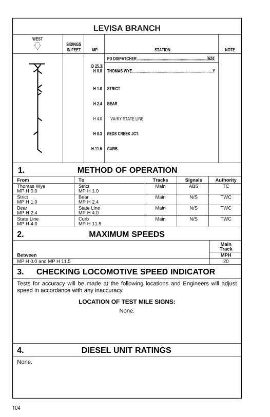
104
LEVISA BRANCHWEST
�� SIDINGSIN FEET MP STATION NOTE
PD DISPATCHER ......................................................................
D 25.3/H 0.0 THOMAS WYE.................................................................................Y
H 1.0 STRICT
H 2.4 BEAR
H 4.0 VA/KY STATE LINE
H 8.3 FEDS CREEK JCT.
H 11.5 CURB
1. METHOD OF OPERATIONFrom To Tracks Signals AuthorityThomas Wye Strict Main ABS TCMP H 0.0 MP H 1.0Strict Bear Main N/S TWCMP H 1.0 MP H 2.4Bear State Line Main N/S TWCMP H 2.4 MP H 4.0State Line Curb Main N/S TWCMP H 4.0 MP H 11.5
2. MAXIMUM SPEEDSMainTrack
Between MPHMP H 0.0 and MP H 11.5 20
3. CHECKING LOCOMOTIVE SPEED INDICATORTests for accuracy will be made at the following locations and Engineers will adjustspeed in accordance with any inaccuracy.
LOCATION OF TEST MILE SIGNS:None.
4. DIESEL UNIT RATINGSNone.
624
105
LEVISA BRANCH
5. LOCOMOTIVE AND CAR RESTRICTIONSNone.
6. SWITCHES AND DERAILSNone.
7. COMMUNICATION INFORMATIONCH-3: TX = 22 RX = 22
8. DETECTOR INSTRUCTIONSNone.
9. DISTRICT INSTRUCTIONSNone.

106
BIG PRATER CREEK SPURWEST
�� SIDINGSIN FEET MP STATION NOTE
PD DISPATCHER ......................................................................
BP 3.5 KOENIG
BP 0.0/ VANSANTD 38.9
1. METHOD OF OPERATIONFrom To Tracks Signals AuthorityKoenig Vansant Main N/S TWCMP BP 3.5 MP BP 0.0
2. MAXIMUM SPEEDSMainTrack
Between MPHMP BP 3.5 and MP BP 0.0 15
3. CHECKING LOCOMOTIVE SPEED INDICATORTests for accuracy will be made at the following locations and Engineers will adjustspeed in accordance with any inaccuracy.
LOCATION OF TEST MILE SIGNS:None.
4. DIESEL UNIT RATINGSNone.
5. LOCOMOTIVE AND CAR RESTRICTIONS
WEIGHT RESTRICTIONS
Loaded 4-axle cars may be handled up to the weight shown provided the stenciledLoad Limit (Weight of car and lading) is NOT exceeded.
286,000 lbs.
6. SWITCHES AND DERAILSNone.
624
BUCH MAIN
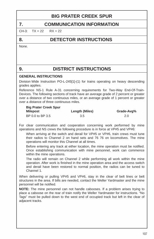
107
BIG PRATER CREEK SPUR
7. COMMUNICATION INFORMATIONCH-3: TX = 22 RX = 22
8. DETECTOR INSTRUCTIONSNone.
9. DISTRICT INSTRUCTIONS
GENERAL INSTRUCTIONSDivision Wide Instruction PO-L-245[1]-(1) for trains operating on heavy descendinggrades applies.Reference NS-1 Rule A-31 concerning requirements for Two-Way End-Of-Train-Devices. The following sections of track have an average grade of 2 percent or greaterover a distance of two continuous miles, or an average grade of 1 percent or greaterover a distance of three continuous miles.
Big Prater Creek SpurMilepost Length (Miles) Grade-Avg%BP 0.0 to BP 3.5 3.5 2.0
For clear communication and cooperation concerning work performed by mineoperations and NS crews the following procedure is in force at VP#5 and VP#6:
When arriving at the switch and derail for VP#5 or VP#6, train crews must tunetheir radios to Channel 2 on hand sets and 76 76 on locomotives. The mineoperations will monitor this Channel at all times.Before entering any track at either location, the mine operation must be notified.Once establishing communication with mine personnel, work can commencewithin the mine operations.The radio will remain on Channel 2 while performing all work within the mineoperation. After work is finished in the mine operation area and the access switchand derail have been restored to normal position, the radios can be tuned toChannel 1.
When delivering or pulling VP#5 and VP#6, stay in the clear of belt lines or beltstructures in the area. If bills are needed, contact the Weller Yardmaster and the minepersonnel will be notified.NOTE: The mine personnel can not handle cabooses. If a problem arises trying toplace a caboose on the rear of train notify the Weller Yardmaster for instructions. “NoTags” must be pulled down to the west end of occupied track but left in the clear ofadjacent tracks.

108
GARDEN CREEK BRANCHWEST
�� SIDINGSIN FEET MP STATION NOTE
PD DISPATCHER ......................................................................
GC 1.1 CORNELIU
GC 0.0/ PAGE JCT. D 48.2
1. METHOD OF OPERATIONFrom To Tracks Signals AuthorityCorneliu Page Jct. Main N/S TWCMP GC 1.1 MP GC 0.0
2. MAXIMUM SPEEDSMainTrack
Between MPHMP GC 1.1 and MP GC 0.0 15
3. CHECKING LOCOMOTIVE SPEED INDICATORTests for accuracy will be made at the following locations and Engineers will adjustspeed in accordance with any inaccuracy.
LOCATION OF TEST MILE SIGNS:None.
4. DIESEL UNIT RATINGSNone.
5. LOCOMOTIVE AND CAR RESTRICTIONS
WEIGHT RESTRICTIONS
Loaded 4-axle cars may be handled up to the weight shown provided the stenciledLoad Limit (Weight of car and lading) is NOT exceeded.
286,000 lbs.
6. SWITCHES AND DERAILSNone.
624

109
GARDEN CREEK BRANCH
7. COMMUNICATION INFORMATIONCH-3: TX = 22 RX = 22
8. DETECTOR INSTRUCTIONSNone.
9. DISTRICT INSTRUCTIONS
GENERAL INSTRUCTIONSDivision Wide Instruction PO-L-245[1]-(1) for trains operating on heavy descendinggrades applies.
Close clearance exists at the following locations:MP GC 2.0 — Island Creek, VP No. 6 Outlet Track
In an effort to increase communication between railroad employees and minepersonnel, the following procedure must be performed when working VP #5 and VP #6.
1. When arriving at the switch and derail for VP #5 or VP #6, train crews must selectChannel 2 on their hand set and Channel 7676 on the Engine radio. VP #5 andVP #6 will monitor this Channel at all times.
2. Before entering any track at either location, the mine operation must be notified.Once establishing communication with the operation, you can continue with yourwork accordingly.
3. While you are working at either operation, you will remain on Channel 2 in order tokeep communication available with the mine. If you need to talk with theYardmaster, you can switch back over to Channel 1 to communicate.
4. Once the work has been completed and you have restored the switch and derail,you will go back to Channel 1 (7272) and be governed accordingly.
Please Note: The mine operations will no longer handle railroad cabooses. If youcannot shove back, nor drop your caboose on, notify the Weller Yardmaster for furtherinstructions.
If there are any “no-tags” on hand, pull them down to the west end of the track in whichthey are located, to the clearance point and prevent from fouling adjacent tracks.
If you are working either industry with insufficient power, it may be at the Engineer’sdiscretion for the handling of “no-tags”.

110
CLINCH VALLEY EXTENSIONWEST
�� SIDINGSIN FEET MP STATION NOTE
NA DISPATCHER......................................................................
CV 458.6/IN 22.9 TACOMA
IN 20.7 DEEP
IN 19.7 RAMSEY
IN 18.5 GRAVE
IN 17.6 HAWTHORNE
IN 17.1 BOPAR
IN 16.7 TANK ...............................................................................................Y
IN 16.4 MILLER
IN 16.2 TEXACO
IN 15.7 FORD
IN 15.4 TOP
IN 15.1 YARD
IN 14.3 DNOR
IN 13.0 JANE
IN 11.7 BLACKWOOD
IN 9.3 KENT................................................................................................Y
IN 8.4 SAWMILL
IN 5.8 ...................................................................................................... 1
IN 4.5 ANDOVER .......................................................................................Y
IN 3.1 ...................................................................................................... 1
IN 2.4 MUDLICK
IN 0.8 OSAKA
IN 0.0 WENTZ
626
YL�
YL�
GLAMORGAN
PARDEE
CV MAIN
T-LINE

111
CLINCH VALLEY EXTENSION
STATION PAGE INFORMATIONNOTE 1: Yard Limits are in effect at Andover, VA on main track between MP IN 3.1 and
MP IN 5.8. Authority for movement within these limits will be granted verbally by theYardmaster at Norton.
1. METHOD OF OPERATIONFrom To Tracks Signals AuthorityTacoma Andover Main N/S TWCMP IN 22.9 MP IN 5.8Andover Andover Main N/S YLMP IN 5.8 MP IN 3.1Andover Wentz Main N/S TWCMP IN 3.1 MP IN 1.0
2. MAXIMUM SPEEDSMainTrack
Between MPHMP IN 22.9 and MP IN 16.0 25
Except:MP IN 17.9 to MP IN 17.5, Curves 15
MP IN 16.0 and MP IN 2.4 20Except:MP IN 6.0, Over Bridge 15MP IN 5.9, Curve 15MP IN 4.8, Scale Track 5
MP IN 2.4 and MP IN 1.0 15
3. CHECKING LOCOMOTIVE SPEED INDICATORTests for accuracy will be made at the following locations and Engineers will adjustspeed in accordance with any inaccuracy.
LOCATION OF TEST MILE SIGNS:WESTWARD EASTWARDMP IN 15.0 to MP IN 14.0 MP IN 7.0 to MP IN 8.0
4. DIESEL UNIT RATINGSDIESEL UNIT RATINGS IN TONS
Group 1 Group 2 Group 3 Group 4 Group 5 Group 6
WestwardNorton to Andover 5000 6650 8000 9900 11000 12980Andover to Mudlick 2400 3200 3850 4725 5250 6195Mudlick to Stonega 1200 1600 1900 2385 2650 3127
EastwardAndover to Kent Jct. 2000 2700 3200 3960 4400 5192Kent Jct. to Norton 1300 1750 2050 2565 2850 3363

112
CLINCH VALLEY EXTENSION
5. LOCOMOTIVE AND CAR RESTRICTIONS
A. WEIGHT RESTRICTIONS
Loaded 4-axle cars may be handled up to the weight shown provided the stenciledLoad Limit (Weight of car and lading) is NOT exceeded.
286,000 lbs.
B. EQUIPMENT RESTRICTIONSTrailing tonnage must be limited on line segments as shown below, behind the followingequipment:1. Empty Multi-level cars.2. Empty Intermodal single-platform flats and such loaded with empty trailers or
containers.3. Empty 85-foot-long or longer flats and such flat cars when loaded with empty trailers
or containers, or loaded with only one trailer or container.4. Empty Intermodal single-axle truck flat car or such cars loaded with empty trailers or
containers.5. Empty single or multiple-unit double-stack (well) cars, or articulated single-platform
(spine) cars. Be governed by Appendix 1 in Eastern and Western Region SystemTimetables.
Maximum safe trailing tonnage behind Restricted equipment between Tacoma Jct. andAndover is as follows:
Eastward — 2800Westward — 2800
6. SWITCHES AND DERAILSNone.
7. COMMUNICATION INFORMATION
NA Dispatcher CH-4: TX = 56 RX = 56 Code 626Norton Yardmaster CH-4: TX = 56 RX = 56 Code 630
CYO 7-589-5979 (Andover) Phone: 1-800-898-4296Fax: 1-800-476-0147
1-800-589-5757
8. DETECTOR INSTRUCTIONSNone.
9. DISTRICT INSTRUCTIONS
GENERAL INSTRUCTIONSLoaded cars exceeding 100 tons gross weight in blocks of 10 more cars will be handledon the head end of trains.

113
CLINCH VALLEY EXTENSION
9. DISTRICT INSTRUCTIONS (CONT.)
GENERAL INSTRUCTIONS (CONT.)Clinch Valley Extension Main Track switch, east leg of Norton Wye, MP IN 16.8, will beleft lined and locked for movement to/from east leg Norton Wye. All movements onClinch Valley Extension Main Track, MP IN 16.8, will proceed expecting to find maintrack switch lined for movement to/from east leg of Norton Wye.
Switch located at the east end of the New Connection Track, Appalachia, MP IN 5.4,will be left lined and locked for movement on the New Connection Track. Junctionswitch located in the vicinity of the Old Ice Plant Crossing, MP IN 5.1, will be left linedand locked for movement on the T-Line.
The main track switch for the yard lead at the west end of Andover Yard, MP IN 3.95,may be left lined as last used. All trains, engines and track equipment must approachthis switch expecting to find it lined against their movement.
The normal position for the junction switch at Mudlick Junction is lined and locked formovement on the Clinch Valley Extension.
Locomotives and Cabooses must not be operated under the tipple at the followinglocation:
Blackwood #2 (Track #2).
Reference NS-1 Rule A-31 concerning requirements for Two-Way End-Of-Train-Devices. The following sections of track have an average grade of 2 percent or greaterover a distance of two continuous miles, or an average grade of 1 percent or greaterover a distance of three continuous miles.
Clinch Valley ExtensionMilepost Length (Miles) Grade-Avg%IN 9.0 to IN 15.3 6.3 1.37
Operating Rule 104(g) “Exception”. The following permanent “blue signal” derails areunder the exclusive control of the Mechanical Department at Andover.
Hand Operated Derails Power Operated DerailsNo. 3 Engine Track No. 3 Engine Track
200 ft. west of the Pit 200 ft. east of west main track switch200 ft. east of the Pit 150 ft. west of east main track switch
Fuel Track Shop Track140 ft. east of the west switch 500 ft. east of west main track switch140 ft. west of the east switch 150 ft. west of east main track switch
Sand Track580 ft. west of main line switch
No. 2 Lead1015 ft. east of the west switch
When setting off loads at Andover Yard, a minimum of 20 percent of train will havehand brakes secured.
When setting off empties at Andover Yard, a minimum of 10 percent of train will havehand brakes secured.
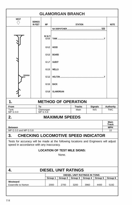
114
GLAMORGAN BRANCHWEST
�� SIDINGSIN FEET MP STATION NOTE
NA DISPATCHER......................................................................
IN 16.7/G 0.0 TANK ...............................................................................................Y
G 0.2 HOOD
G 0.3 BOARD
G 1.7 GUEST
G 2.5 WELLS
G 3.2 HOLTON ..........................................................................................Y
G 3.5 BACK
G 5.8 GLAMORGAN
1. METHOD OF OPERATIONFrom To Tracks Signals AuthorityTank Glamorgan Main N/S TWCMP G 0.0 MP G 5.8
2. MAXIMUM SPEEDSMainTrack
Between MPHMP G 0.0 and MP G 5.8 10
3. CHECKING LOCOMOTIVE SPEED INDICATORTests for accuracy will be made at the following locations and Engineers will adjustspeed in accordance with any inaccuracy.
LOCATION OF TEST MILE SIGNS:None.
4. DIESEL UNIT RATINGSDIESEL UNIT RATINGS IN TONS
Group 1 Group 2 Group 3 Group 4 Group 5 Group 6
WestwardEsserville to Norton 2000 2700 3200 3960 4400 5192
626
DIXIANA

115
GLAMORGAN BRANCH
5. LOCOMOTIVE AND CAR RESTRICTIONSNone.
6. SWITCHES AND DERAILSNone.
7. COMMUNICATION INFORMATIONCH-4: TX = 56 RX = 56
8. DETECTOR INSTRUCTIONSNone.
9. DISTRICT INSTRUCTIONS
GENERAL INSTRUCTIONSThe junction switch at Holton, MP G 3.2 will be left lined and locked for movementto/from Dixiana Branch. All movements on Glamorgan Branch Main Track, MP G 3.2,will proceed expecting to find main track switch lined for movement to/from DixianaBranch.
Loaded cars exceeding 100 tons gross weight in blocks of 10 or more cars will behandled on the head end of trains.
Locomotives and cabooses must not be operated under the tipple at the followinglocations:
Hood (No. 2 Track)BrutonEsserville
Crews holding a valid Track Warrant from Tank, MP G 0.0 to Board, MP G 0.3, for theGlamorgan Branch, will have permission to use both legs of the Wye. Crews cannotrelease these limits while occupying the Wye.

116
DIXIANA BRANCHWEST
�� SIDINGSIN FEET MP STATION NOTE
NA DISPATCHER......................................................................
G 3.2/GD 0.0 HOLTON ..........................................................................................Y
GD 1.5 HOLLOW
GD 4.1 BELL
GD 5.3 RIVER
GD 5.6 DOUG
GD 6.0 DUST............................................................................................
GD 6.7 DIXIANA.......................................................................................
1. METHOD OF OPERATIONFrom To Tracks Signals AuthorityHolton Dust Main N/S TWCMP GD 0.0 MP GD 6.0Dust Dixiana 105MP GD 6.0 MP GD 6.7
2. MAXIMUM SPEEDSMainTrack
Between MPHMP GD 0.0 and MP GD 6.7 10
3. CHECKING LOCOMOTIVE SPEED INDICATORTests for accuracy will be made at the following locations and Engineers will adjustspeed in accordance with any inaccuracy.
LOCATION OF TEST MILE SIGNS:None.
4. DIESEL UNIT RATINGSNone.
626
YL�
YL�
GLA BR.
117
DIXIANA BRANCH
5. LOCOMOTIVE AND CAR RESTRICTIONS
WEIGHT RESTRICTIONS
Loaded 4-axle cars may be handled up to the weight shown provided the stenciledLoad Limit (Weight of car and lading) is NOT exceeded.
286,000 lbs.
6. SWITCHES AND DERAILSNone.
7. COMMUNICATION INFORMATIONCH-4: TX = 56 RX = 56
8. DETECTOR INSTRUCTIONSNone.
9. DISTRICT INSTRUCTIONS
GENERAL INSTRUCTIONSWhen equipment is left unattended, standing on Dixiana Branch Main Track west ofSteer Branch Tipple, MP GD 6.7, the Dixiana Branch Main Track switch west end ofRunaround Track, MP GD 6.7, will be left lined and locked for movement to/fromRunaround Track.
The junction switch at Holton, MP GD 0.0, will be left lined and locked for movementto/from Dixiana Branch.
Loaded cars exceeding 100 tons gross weight, in blocks of 10 or more cars will behandled on the head end of trains.
Crews holding a valid Track Warrant from Holton, MP GD 0.0 to Hollow, MP GD 1.5, forthe Dixiana Branch, will have permission to use both legs of the Wye. Crews cannotrelease these limits while occupying the Wye.
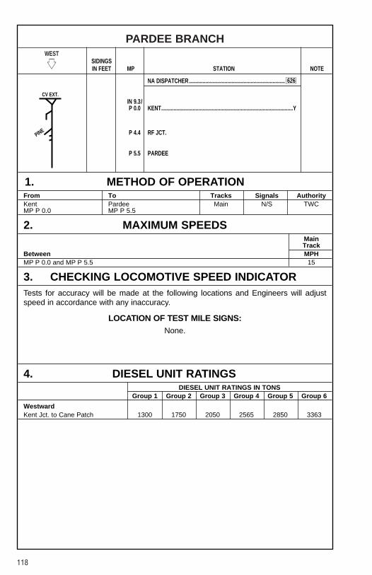
118
PARDEE BRANCHWEST
�� SIDINGSIN FEET MP STATION NOTE
NA DISPATCHER......................................................................
IN 9.3/P 0.0 KENT................................................................................................Y
P 4.4 RF JCT.
P 5.5 PARDEE
1. METHOD OF OPERATIONFrom To Tracks Signals AuthorityKent Pardee Main N/S TWCMP P 0.0 MP P 5.5
2. MAXIMUM SPEEDSMainTrack
Between MPHMP P 0.0 and MP P 5.5 15
3. CHECKING LOCOMOTIVE SPEED INDICATORTests for accuracy will be made at the following locations and Engineers will adjustspeed in accordance with any inaccuracy.
LOCATION OF TEST MILE SIGNS:None.
4. DIESEL UNIT RATINGSDIESEL UNIT RATINGS IN TONS
Group 1 Group 2 Group 3 Group 4 Group 5 Group 6
WestwardKent Jct. to Cane Patch 1300 1750 2050 2565 2850 3363
626
PINE
CV EXT.
119
PARDEE BRANCH
5. LOCOMOTIVE AND CAR RESTRICTIONSNone.
6. SWITCHES AND DERAILSNone.
7. COMMUNICATION INFORMATIONCH-4: TX = 56 RX = 56
8. DETECTOR INSTRUCTIONSNone.
9. DISTRICT INSTRUCTIONS
GENERAL INSTRUCTIONSDivision Wide Instruction PO-L-245[1]-(1) for trains operating on heavy descendinggrades applies.
Loaded cars exceeding 100 tons gross weight in blocks of 10 or more cars will behandled on the head end of trains.
Account curvature on Pardee Branch westward shoving movements with more than 75empty cars must not be made between MP P 0.7 and MP P 7.7 unless Helper Engineis coupled to west end of movement and being operated within one notch of the samethrottle position as head end power. The combination of head end and Helper Unitsmust not exceed the equivalent of 24 powered conventional axles. The number ofequivalent powered axles on the Helper Engine must be adjusted as nearly as possibleto that of the head end power.
Reference NS-1 Rule A-31 concerning requirements for Two-Way End-Of-Train-Devices. The following sections of track have an average grade of 2 percent of greaterover a distance of two continuous miles, or an average grade of 1 percent or greaterover a distance of three continuous miles.
Pardee BranchMilepost Length (Miles) Grade-Avg%P 4.8 to P 7.7 3.2 1.84
Crews holding a valid Track Warrant from Kent, MP P 0.0 to RF Junction, MP P 4.4, forthe Pardee Branch, will have permission to use both legs of the Wye. Crews cannotrelease these limits while occupying the Wye.

120
PINE BRANCHWEST
�� SIDINGSIN FEET MP STATION NOTE
NA DISPATCHER......................................................................
P 4.4/PB 0.0 RF JCT.
PB 3.8 PINE
1. METHOD OF OPERATIONFrom To Tracks Signals AuthorityRF Jct. Pine Main N/S TWCMP PB 0.0 MP PB 3.8
2. MAXIMUM SPEEDSMainTrack
Between MPHMP PB 0.0 and MP PB 3.8 15
3. CHECKING LOCOMOTIVE SPEED INDICATORTests for accuracy will be made at the following locations and Engineers will adjustspeed in accordance with any inaccuracy.
LOCATION OF TEST MILE SIGNS:None.
4. DIESEL UNIT RATINGSNone.
626
PARD BR.

121
PINE BRANCH
5. LOCOMOTIVE AND CAR RESTRICTIONSNone.
6. SWITCHES AND DERAILSNone.
7. COMMUNICATION INFORMATIONCH-4: TX = 56 RX = 56
8. DETECTOR INSTRUCTIONSNone.
9. DISTRICT INSTRUCTIONS
GENERAL INSTRUCTIONSDivision Wide Instruction PO-L-245[1]-(1) for trains operating on heavy descendinggrades applies.
Loaded cars exceeding 100 tons gross weight in blocks of 10 or more cars will behandled on the head end of trains.
Locomotives and Cabooses must not be operated under tipple at the followinglocations:
Roaring Fork Tipple
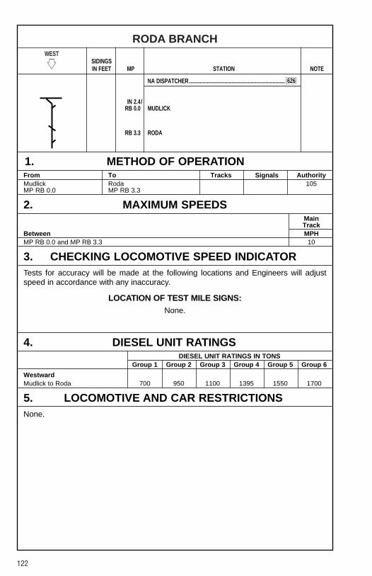
122
RODA BRANCHWEST
�� SIDINGSIN FEET MP STATION NOTE
NA DISPATCHER......................................................................
IN 2.4/RB 0.0 MUDLICK
RB 3.3 RODA
1. METHOD OF OPERATIONFrom To Tracks Signals AuthorityMudlick Roda 105MP RB 0.0 MP RB 3.3
2. MAXIMUM SPEEDSMainTrack
Between MPHMP RB 0.0 and MP RB 3.3 10
3. CHECKING LOCOMOTIVE SPEED INDICATORTests for accuracy will be made at the following locations and Engineers will adjustspeed in accordance with any inaccuracy.
LOCATION OF TEST MILE SIGNS:None.
4. DIESEL UNIT RATINGSDIESEL UNIT RATINGS IN TONS
Group 1 Group 2 Group 3 Group 4 Group 5 Group 6
WestwardMudlick to Roda 700 950 1100 1395 1550 1700
5. LOCOMOTIVE AND CAR RESTRICTIONSNone.
626

123
RODA BRANCH
6. SWITCHES AND DERAILSNone.
7. COMMUNICATION INFORMATIONCH-4: TX = 56 RX = 56
8. DETECTOR INSTRUCTIONSNone.
9. DISTRICT INSTRUCTIONS
GENERAL INSTRUCTIONSDivision Wide Instruction PO-L-245[1]-(1) for trains operating on heavy descendinggrades applies.
Loaded cars exceeding 100 tons gross weight, in blocks of 10 or more cars will behandled on the head end of trains.
Employees servicing Roda Tipple, MP RB 0.6, will use extreme caution and complywith the above instructions. Employees are to make sure that the tipple chute isfully retracted and clear of the tracks before passing under it. Also, employees will notallow engines or cabooses to pass under the tipple.
Reference NS-1 Rule A-31 concerning requirements for Two-Way End-Of-Train-Devices. The following sections of track have an average grade of 2 percent or greaterover a distance of two continuous miles, or an average grade of 1 percent or greaterover a distance of three continuous miles.
Roda BranchMilepost Length (Miles) Grade-Avg%RB 0.0 to RB 3.3 3.3 1.76
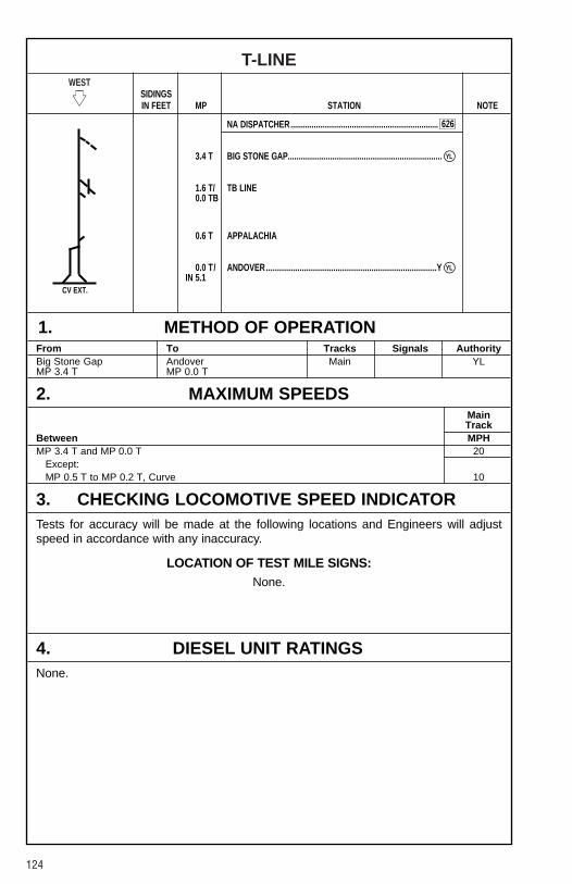
124
T-LINEWEST
�� SIDINGSIN FEET MP STATION NOTE
NA DISPATCHER......................................................................
3.4 T BIG STONE GAP.........................................................................
1.6 T/ TB LINE0.0 TB
0.6 T APPALACHIA
0.0 T/ ANDOVER.................................................................................Y IN 5.1
1. METHOD OF OPERATIONFrom To Tracks Signals AuthorityBig Stone Gap Andover Main YLMP 3.4 T MP 0.0 T
2. MAXIMUM SPEEDSMainTrack
Between MPHMP 3.4 T and MP 0.0 T 20
Except:MP 0.5 T to MP 0.2 T, Curve 10
3. CHECKING LOCOMOTIVE SPEED INDICATORTests for accuracy will be made at the following locations and Engineers will adjustspeed in accordance with any inaccuracy.
LOCATION OF TEST MILE SIGNS:None.
4. DIESEL UNIT RATINGSNone.
626
YL�
YL�
CV EXT.
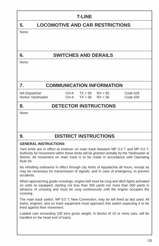
125
T-LINE
5. LOCOMOTIVE AND CAR RESTRICTIONSNone.
6. SWITCHES AND DERAILSNone.
7. COMMUNICATION INFORMATION
NA Dispatcher CH-4: TX = 56 RX = 56 Code 626Norton Yardmaster CH-4: TX = 56 RX = 56 Code 630
8. DETECTOR INSTRUCTIONSNone.
9. DISTRICT INSTRUCTIONS
GENERAL INSTRUCTIONSYard limits are in effect at Andover on main track between MP 3.4 T and MP 0.0 T.Authority for movement within these limits will be granted verbally by the Yardmaster atNorton. All movement on main track is to be made in accordance with OperatingRule 93.
No whistling ordinance in effect through city limits of Appalachia all hours, except asmay be necessary for transmission of signals, and in case of emergency, to preventaccidents.
When approaching grade crossings, engine bell must be rung and ditch lights activatedon units so equipped, starting not less than 300 yards nor more than 600 yards inadvance of crossing and must be rung continuously until the engine occupies thecrossing.
The main track switch, MP 0.5 T, New Connection, may be left lined as last used. Alltrains, engines, and on track equipment must approach this switch expecting it to belined against their movement.
Loaded cars exceeding 100 tons gross weight, in blocks of 10 or more cars, will behandled on the head end of trains.

126
ST. CHARLES BRANCHWEST
�� SIDINGSIN FEET MP STATION NOTE
NA DISPATCHER......................................................................
1.6 T/0.0 TB ANDOVER....................................................................................
1.0 TB ......................................................................................................
2.6 TB IMBODEN
4.4 TB CREST
6.5 TB KEOKEE
10.5 TB BUNDY
19.5 TB POCKETT
21.4 TB ......................................................................................................
22.5 TB ST. CHARLES .................................................................................Y
25.5 TB ......................................................................................................
1. METHOD OF OPERATIONFrom To Tracks Signals AuthorityAndover Andover Main YLMP 0.0 TB MP 1.0 TB Andover St. Charles Main N/S TWCMP 1.0 TB MP 21.4 TB St. Charles St. Charles Main YLMP 21.4 TB MP 25.5 TB
2. MAXIMUM SPEEDSMainTrack
Between MPHMP 0.0 TB and MP 0.2 TB 15MP 0.2 TB and MP 9.0 TB 20
Except:MP 0.0 TB to MP 5.0 TB, Loaded Trains 10
MP 9.0 TB and MP 18.0 TB 15MP 18.0 TB and MP 20.3 TB 20MP 20.3 TB and MP 23.8 TB 15MP 23.8 TB and MP 25.5 TB 10
626
YL�
YL�
YL�
YL�
CALVIN
SP
CSXT
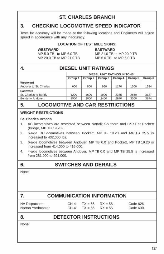
127
ST. CHARLES BRANCH
3. CHECKING LOCOMOTIVE SPEED INDICATORTests for accuracy will be made at the following locations and Engineers will adjustspeed in accordance with any inaccuracy.
LOCATION OF TEST MILE SIGNS:WESTWARD EASTWARDMP 5.0 TB to MP 6.0 TB MP 21.0 TB to MP 20.0 TBMP 20.0 TB to MP 21.0 TB MP 6.0 TB to MP 5.0 TB
4. DIESEL UNIT RATINGSDIESEL UNIT RATINGS IN TONS
Group 1 Group 2 Group 3 Group 4 Group 5 Group 6
WestwardAndover to St. Charles 600 800 950 1170 1300 1534
EastwardSt. Charles to Bundy 1200 1600 1900 2385 2650 3127Bundy to Andover 1500 2000 2400 2970 3300 3894
5. LOCOMOTIVE AND CAR RESTRICTIONS
WEIGHT RESTRICTIONS
St. Charles Branch1. AC locomotives are restricted between Norfolk Southern and CSXT at Pockett
(Bridge, MP TB 19.20).2. 6-axle DC locomotives between Pockett, MP TB 19.20 and MP TB 25.5 is
increased to 432,000 lbs.3. 6-axle locomotives between Andover, MP TB 0.0 and Pockett, MP TB 19.20 is
increased from 414,000 to 416,000.4. 4-axle locomotives between Andover, MP TB 0.0 and MP TB 25.5 is increased
from 281,000 to 291,000.
6. SWITCHES AND DERAILSNone.
7. COMMUNICATION INFORMATION
NA Dispatcher CH-4: TX = 56 RX = 56 Code 626Norton Yardmaster CH-4: TX = 56 RX = 56 Code 630
8. DETECTOR INSTRUCTIONSNone.
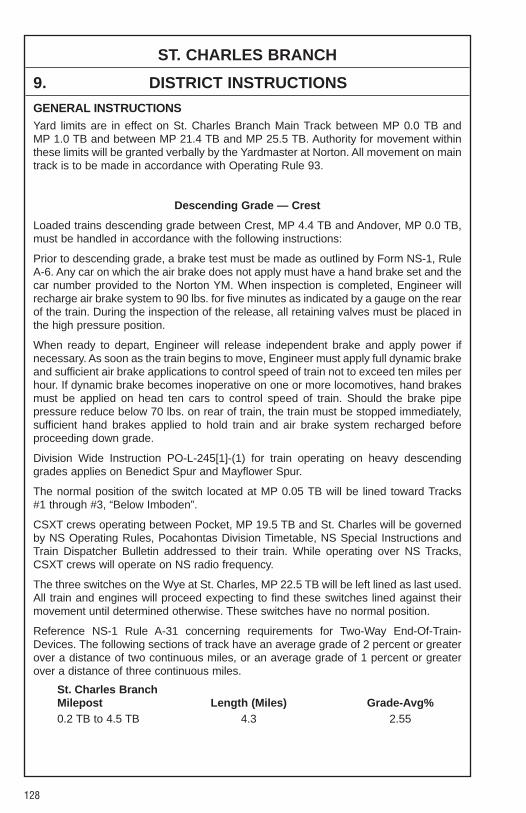
128
ST. CHARLES BRANCH
9. DISTRICT INSTRUCTIONS
GENERAL INSTRUCTIONSYard limits are in effect on St. Charles Branch Main Track between MP 0.0 TB andMP 1.0 TB and between MP 21.4 TB and MP 25.5 TB. Authority for movement withinthese limits will be granted verbally by the Yardmaster at Norton. All movement on maintrack is to be made in accordance with Operating Rule 93.
Descending Grade — Crest
Loaded trains descending grade between Crest, MP 4.4 TB and Andover, MP 0.0 TB,must be handled in accordance with the following instructions:
Prior to descending grade, a brake test must be made as outlined by Form NS-1, RuleA-6. Any car on which the air brake does not apply must have a hand brake set and thecar number provided to the Norton YM. When inspection is completed, Engineer willrecharge air brake system to 90 lbs. for five minutes as indicated by a gauge on the rearof the train. During the inspection of the release, all retaining valves must be placed inthe high pressure position.
When ready to depart, Engineer will release independent brake and apply power ifnecessary. As soon as the train begins to move, Engineer must apply full dynamic brakeand sufficient air brake applications to control speed of train not to exceed ten miles perhour. If dynamic brake becomes inoperative on one or more locomotives, hand brakesmust be applied on head ten cars to control speed of train. Should the brake pipepressure reduce below 70 lbs. on rear of train, the train must be stopped immediately,sufficient hand brakes applied to hold train and air brake system recharged beforeproceeding down grade.
Division Wide Instruction PO-L-245[1]-(1) for train operating on heavy descendinggrades applies on Benedict Spur and Mayflower Spur.
The normal position of the switch located at MP 0.05 TB will be lined toward Tracks #1 through #3, “Below Imboden”.
CSXT crews operating between Pocket, MP 19.5 TB and St. Charles will be governedby NS Operating Rules, Pocahontas Division Timetable, NS Special Instructions andTrain Dispatcher Bulletin addressed to their train. While operating over NS Tracks,CSXT crews will operate on NS radio frequency.
The three switches on the Wye at St. Charles, MP 22.5 TB will be left lined as last used.All train and engines will proceed expecting to find these switches lined against theirmovement until determined otherwise. These switches have no normal position.
Reference NS-1 Rule A-31 concerning requirements for Two-Way End-Of-Train-Devices. The following sections of track have an average grade of 2 percent or greaterover a distance of two continuous miles, or an average grade of 1 percent or greaterover a distance of three continuous miles.
St. Charles BranchMilepost Length (Miles) Grade-Avg%0.2 TB to 4.5 TB 4.3 2.55
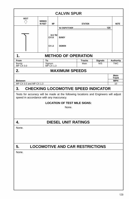
129
CALVIN SPURWEST
�� SIDINGSIN FEET MP STATION NOTE
NA DISPATCHER......................................................................
10.5 TB/CX 0.0 BUNDY
CX 1.3 SIGMON
1. METHOD OF OPERATIONFrom To Tracks Signals AuthorityBundy Sigmon Main N/S TWCMP CX 0.0 MP CX 1.3
2. MAXIMUM SPEEDSMainTrack
Between MPHMP CX 0.0 and MP CX 1.3 10
3. CHECKING LOCOMOTIVE SPEED INDICATORTests for accuracy will be made at the following locations and Engineers will adjustspeed in accordance with any inaccuracy.
LOCATION OF TEST MILE SIGNS:None.
4. DIESEL UNIT RATINGSNone.
5. LOCOMOTIVE AND CAR RESTRICTIONSNone.
626
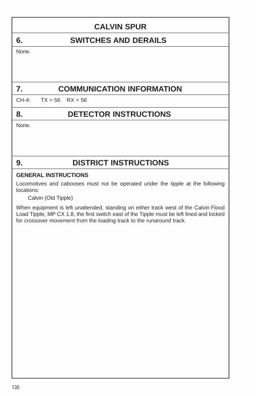
130
CALVIN SPUR
6. SWITCHES AND DERAILSNone.
7. COMMUNICATION INFORMATIONCH-4: TX = 56 RX = 56
8. DETECTOR INSTRUCTIONSNone.
9. DISTRICT INSTRUCTIONS
GENERAL INSTRUCTIONSLocomotives and cabooses must not be operated under the tipple at the followinglocations:
Calvin (Old Tipple)
When equipment is left unattended, standing on either track west of the Calvin FloodLoad Tipple, MP CX 1.8, the first switch east of the Tipple must be left lined and lockedfor crossover movement from the loading track to the runaround track.
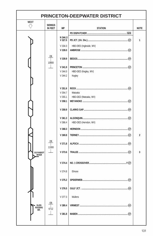
131
PRINCETON-DEEPWATER DISTRICTWEST
�� SIDINGSIN FEET MP STATION NOTE
PD DISPATCHER ......................................................................
N 344.1/V 327.0 PD JCT. (Vir. Div.) ....................................................................... 1
V 334.3 HBD-DED (Ingleside, WV)
V 339.0 AMBROSE ...................................................................................
V 339.9 BEGGS.........................................................................................
V 341.9 PRINCETON ................................................................................
V 344.0 HBD-DED (Kegley, WV)
V 344.2 Kegley
V 351.6 ROCK ...........................................................................................
V 354.7 Matoaka
V 355.1 HBD-DED (Matoaka, WV)
V 358.1 WEYANOKE ................................................................................
V 359.9 CLARKS GAP..............................................................................
V 361.3 ALGONQUIN................................................................................
V 366.4 HBD-DED (Herndon, WV)
V 368.3 HERNDON ...................................................................................
V 369.8 TIERNEY ...................................................................................... 2
V 371.8 ALPOCA ......................................................................................
V 373.6 TRALEE ....................................................................................... 3
V 374.4 NO. 1 CROSSOVER..................................................................Y
V 374.8 Elmore
V 375.2 SPIDERWEB................................................................................
V 376.5 GULF JCT. ..................................................................................
V 377.3 Mullens
V 380.4 VIRWEST .....................................................................................
V 381.8 MABEN ........................................................................................
CP�
CP�
CP�
CP�
CP�
CP�
CP�
CP�
CP�
CP�
CP�
CP�
CP�
CP�
CP�
CP�
CP�
10800
11000
6712
GUYANDOTRIVER
GLENROGERS
BR.
CS
CS
CS
624
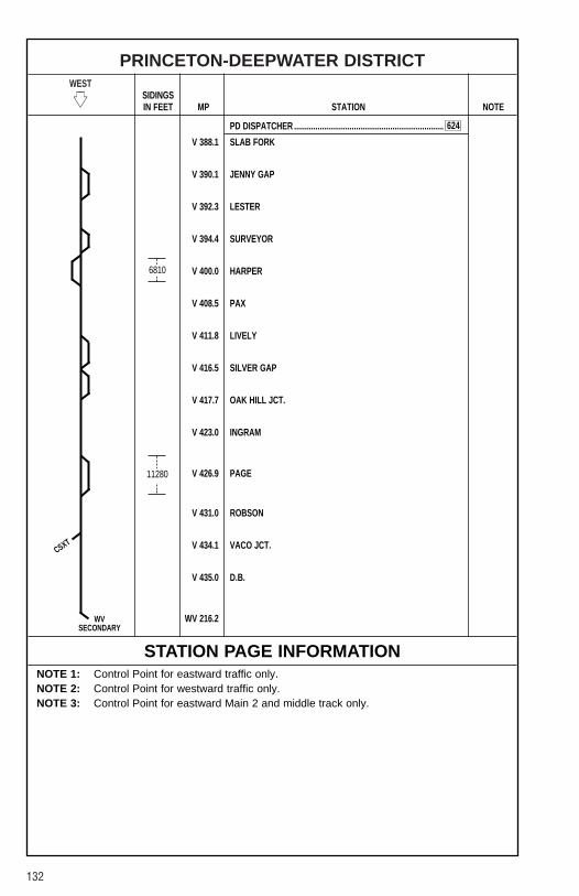
132
PRINCETON-DEEPWATER DISTRICTWEST
�� SIDINGSIN FEET MP STATION NOTE
PD DISPATCHER ......................................................................
V 388.1 SLAB FORK
V 390.1 JENNY GAP
V 392.3 LESTER
V 394.4 SURVEYOR
V 400.0 HARPER
V 408.5 PAX
V 411.8 LIVELY
V 416.5 SILVER GAP
V 417.7 OAK HILL JCT.
V 423.0 INGRAM
V 426.9 PAGE
V 431.0 ROBSON
V 434.1 VACO JCT.
V 435.0 D.B.
WV 216.2
STATION PAGE INFORMATIONNOTE 1: Control Point for eastward traffic only.NOTE 2: Control Point for westward traffic only.NOTE 3: Control Point for eastward Main 2 and middle track only.
6810
11280
CSXT
624
WVSECONDARY
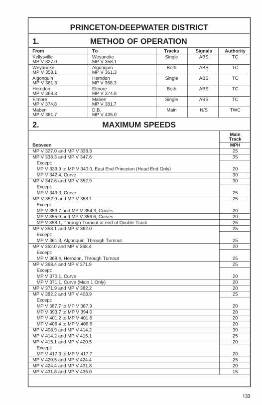
133
PRINCETON-DEEPWATER DISTRICT
1. METHOD OF OPERATIONFrom To Tracks Signals AuthorityKellysville Weyanoke Single ABS TCMP V 327.0 MP V 358.1Weyanoke Algonquin Both ABS TCMP V 358.1 MP V 361.3Algonquin Herndon Single ABS TCMP V 361.3 MP V 368.3Herndon Elmore Both ABS TCMP V 368.3 MP V 374.8Elmore Maben Single ABS TCMP V 374.8 MP V 381.7Maben D.B. Main N/S TWCMP V 381.7 MP V 435.0
2. MAXIMUM SPEEDSMainTrack
Between MPHMP V 327.0 and MP V 338.3 25MP V 338.3 and MP V 347.6 35
Except:MP V 339.9 to MP V 340.0, East End Princeton (Head End Only) 20MP V 342.4, Curve 30
MP V 347.6 and MP V 352.9 30Except:MP V 349.3, Curve 25
MP V 352.9 and MP V 358.1 25Except:MP V 353.7 and MP V 354.3, Curves 20MP V 355.9 and MP V 356.6, Curves 20MP V 358.1, Through Turnout at end of Double Track 25
MP V 358.1 and MP V 362.0 25Except:MP V 361.3, Algonquin, Through Turnout 25
MP V 362.0 and MP V 368.4 20Except:MP V 368.4, Herndon, Through Turnout 25
MP V 368.4 and MP V 371.9 25Except:MP V 370.1, Curve 20MP V 371.1, Curve (Main 1 Only) 20
MP V 371.9 and MP V 382.2 20MP V 382.2 and MP V 408.9 25
Except:MP V 387.7 to MP V 387.9 20MP V 393.7 to MP V 394.0 20MP V 401.2 to MP V 401.6 20MP V 406.4 to MP V 406.6 20
MP V 408.9 and MP V 414.2 30MP V 414.2 and MP V 415.1 25MP V 415.1 and MP V 420.5 20
Except:MP V 417.3 to MP V 417.7 20
MP V 420.5 and MP V 424.4 25MP V 424.4 and MP V 431.8 20MP V 431.8 and MP V 435.0 15
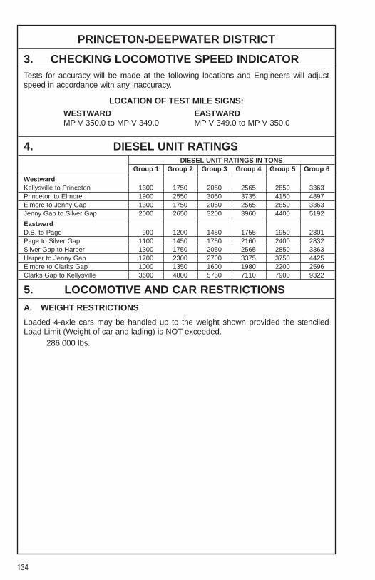
134
PRINCETON-DEEPWATER DISTRICT
3. CHECKING LOCOMOTIVE SPEED INDICATORTests for accuracy will be made at the following locations and Engineers will adjustspeed in accordance with any inaccuracy.
LOCATION OF TEST MILE SIGNS:WESTWARD EASTWARDMP V 350.0 to MP V 349.0 MP V 349.0 to MP V 350.0
4. DIESEL UNIT RATINGSDIESEL UNIT RATINGS IN TONS
Group 1 Group 2 Group 3 Group 4 Group 5 Group 6
WestwardKellysville to Princeton 1300 1750 2050 2565 2850 3363Princeton to Elmore 1900 2550 3050 3735 4150 4897Elmore to Jenny Gap 1300 1750 2050 2565 2850 3363Jenny Gap to Silver Gap 2000 2650 3200 3960 4400 5192
EastwardD.B. to Page 900 1200 1450 1755 1950 2301Page to Silver Gap 1100 1450 1750 2160 2400 2832Silver Gap to Harper 1300 1750 2050 2565 2850 3363Harper to Jenny Gap 1700 2300 2700 3375 3750 4425Elmore to Clarks Gap 1000 1350 1600 1980 2200 2596Clarks Gap to Kellysville 3600 4800 5750 7110 7900 9322
5. LOCOMOTIVE AND CAR RESTRICTIONS
A. WEIGHT RESTRICTIONS
Loaded 4-axle cars may be handled up to the weight shown provided the stenciledLoad Limit (Weight of car and lading) is NOT exceeded.
286,000 lbs.

135
PRINCETON-DEEPWATER DISTRICT
5. LOCOMOTIVE AND CAR RESTRICTIONS (CONT.)
B. EQUIPMENT RESTRICTIONSTrailing tonnage must be limited on line segments as shown below, behind the followingequipment:1. Empty Multi-level cars.2. Empty Intermodal single-platform flats and such loaded with empty trailers or
containers.3. Empty 85-foot-long or longer flats and such flat cars when loaded with empty trailers
or containers, or loaded with only one trailer or container.4. Empty Intermodal single-axle truck flat car or such cars loaded with empty trailers or
containers.5. Empty single or multiple-unit double-stack (well) cars, or articulated single-platform
(spine) cars. Be governed by Appendix 1 in Eastern and Western Region SystemTimetables.
Maximum safe trailing tonnage behind Restricted equipment between Elmore andDeepwater is as follows:
Eastward — 1500Westward — 2200
Maximum safe trailing tonnage behind Restricted equipment between Kellysville andElmore is as follows:
Eastward — 2100Westward — 2500
C. HEIGHT RESTRICTIONSMulti-levels and Hy-Cube cars can not be handled between Kellysville and Deepwater.Cars exceeding Plate “C” must not be handled between Kellysville and Elmore unlessspecially authorized.
Cars exceeding Plate “E” must not be handled between Elmore and Deepwater unlessspecially authorized.
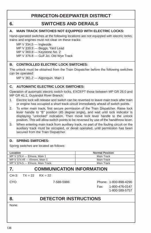
136
PRINCETON-DEEPWATER DISTRICT
6. SWITCHES AND DERAILS
A. MAIN TRACK SWITCHES NOT EQUIPPED WITH ELECTRIC LOCKS:Hand-operated switches at the following locations are not equipped with electric locks,trains and engines must not clear on these tracks:
MP V 334.5 — InglesideMP V 339.9 — Beggs, Yard Lead MP V 369.8 — Keystone No. 2MP V 376.8 — Gulf Jct. Old Wye Track
B. CONTROLLED ELECTRIC LOCK SWITCHES:The unlock must be obtained from the Train Dispatcher before the following switchescan be operated:
MP V 361.2 — Algonquin, Main 1
C. AUTOMATIC ELECTRIC LOCK SWITCHES:Operation of automatic electric switch locks, EXCEPT those between MP GR 26.0 andMP GR 41.1, Guyandot River Branch:1. Electric lock will release and switch can be reversed to leave main track after train
or engine has occupied a short track circuit immediately ahead of switch points.2. To enter main track, first secure permission of the Train Dispatcher. Raise lock
lever handle to “B” position (45 degree angle), and wait until lock indicator isdisplaying “unlocked” indication. Then move lock lever handle to the unlockposition. This will allow switch points to be reversed by use of the handthrow lever.
3. When entering main track from auxiliary track, no part of the fouling circuit on theauxiliary track must be occupied, or derail operated, until permission has beensecured from the Train Dispatcher.
D. SPRING SWITCHES:Spring switches are located as follows:
Location Normal PositionMP V 374.4 — Elmore, Main 1 Main TrackMP V 374.45 — Elmore, Main 1 Main TrackMP V 374.5 — Elmore, Main Track Main Track
7. COMMUNICATION INFORMATIONCH-3: TX = 22 RX = 22
CYO 7-589-5986 Phone: 1-800-898-4296Fax: 1-800-476-0147
1-800-589-5757
8. DETECTOR INSTRUCTIONSNone.

137
PRINCETON-DEEPWATER DISTRICT
9. DISTRICT INSTRUCTIONS
GENERAL INSTRUCTIONSPrinceton-Deepwater District
Division Wide Instruction PO-L-245[1]-(1) for trains operating on heavy descendinggrades applies on Beard’s Fork Branch.
The Radio, “Ivy Knob” in service for Emergency Only. The Access code must be senttwice to help avoid accidental use.
Operating Rule 104(g) “EXCEPTION”. The following permanent “Blue Signal” derailsare under the exclusive control of the Mechanical Department.
Princeton Coal Track 260 feet to switch pointPrinceton — West end No. 2 268 feet to switch pointand No. 7 Tracks on Lead
The proper alignment for the connection switch for the Glen Rogers Branch at Virwestis for the Glen Rogers Branch.
CSXT trains may use NS trackage between MP V 433.5 and D.B. and between Oak HillJunction and Carlisle under the direction of the NS Dispatcher in Bluefield.
NS Rules govern CSXT trains on NS Track.
Reference NS-1 Rule A-31 concerning requirements for Two-Way End-Of-Train-Devices. The following sections of track have an average grade of 2 percent or greaterover a distance of two continuous miles, or an average grade of 1 percent or greaterover a distance of three continuous miles.
Princeton-Deepwater DistrictMilepost Length (Miles) Grade-Avg%V 327.8 to V 338.4 10.6 1.34V 361.5 to V 374.0 12.5 1.44V 385.5 to V 390.4 4.9 1.61V 400.8 to V 406.3 5.5 1.52V 417.0 to V 426.0 9.0 1.56V 428.8 to V 435.0 6.2 1.3
White Oak BranchDivision Wide Instruction PO-L-245[1]-(1) for trains operating on heavy descendinggrades applies.
Highway crossings requiring flag protection when trains or engines are operated oversuch crossings:
Mile Post State RouteBranch Line Location NumberWhite Oak Branch WL 1.0 + 528 ft. Route 61
Old Station Siding Switch, MP WL 1.4, is used as a switch point derail. Any cars orequipment left standing must be left west of this derail.

138
WINDING GULF BRANCHWEST
�� SIDINGSIN FEET MP STATION NOTE
PD DISPATCHER ......................................................................
V 376.5/ GULF JCT. ..................................................................................WG 0.0
WG 1.4 BLACK EAGLE
WG 6.5 HORSEPEN .................................................................................
WG 7.5 AMIGO .........................................................................................
WG 9.9 HELEN
WG 12.1 TAMS ...........................................................................................
WG 14.2 STOTESBURY
WG 21.1 SOPHIA
WG 23.6 PEMBERTON
WG 29.3 BOWYER
1. METHOD OF OPERATIONFrom To Tracks Signals AuthorityGulf Jct. Tams Single ABS TCMP V 376.5 MP WG 12.3Amigo East Gulf Main N/S TWCMP WG 7.5/MP ST 0.0 MP ST 2.9Tams Pemberton Main N/S TWCMP WG 12.3 MP WG 22.5Pemberton Pemberton Main N/S YLMP WG 22.5 MP WG 23.7Pemberton Bowyer Main N/S TWCMP WG 23.5 MP WG 29.3
2. MAXIMUM SPEEDSMainTrack
Between MPHMP WG 0.0 and MP WG 7.5 20MP WG 7.5 and MP WG 29.3 10Auxiliary Tracks:
MP WG 7.5, Stone Coal Br. 15
4381
7500
CS
624
CP�
CP�
CP�
CP�
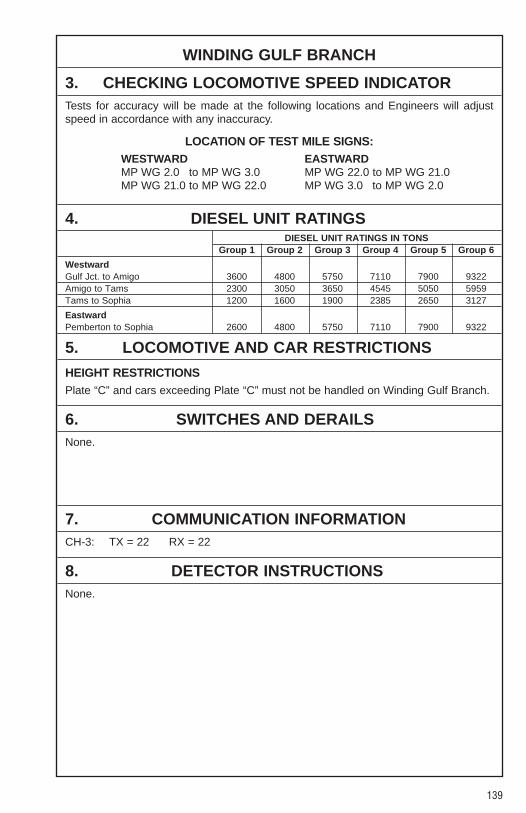
139
WINDING GULF BRANCH
3. CHECKING LOCOMOTIVE SPEED INDICATORTests for accuracy will be made at the following locations and Engineers will adjustspeed in accordance with any inaccuracy.
LOCATION OF TEST MILE SIGNS:WESTWARD EASTWARDMP WG 2.0 to MP WG 3.0 MP WG 22.0 to MP WG 21.0MP WG 21.0 to MP WG 22.0 MP WG 3.0 to MP WG 2.0
4. DIESEL UNIT RATINGSDIESEL UNIT RATINGS IN TONS
Group 1 Group 2 Group 3 Group 4 Group 5 Group 6
WestwardGulf Jct. to Amigo 3600 4800 5750 7110 7900 9322Amigo to Tams 2300 3050 3650 4545 5050 5959Tams to Sophia 1200 1600 1900 2385 2650 3127
EastwardPemberton to Sophia 2600 4800 5750 7110 7900 9322
5. LOCOMOTIVE AND CAR RESTRICTIONS
HEIGHT RESTRICTIONSPlate “C” and cars exceeding Plate “C” must not be handled on Winding Gulf Branch.
6. SWITCHES AND DERAILSNone.
7. COMMUNICATION INFORMATIONCH-3: TX = 22 RX = 22
8. DETECTOR INSTRUCTIONSNone.

140
WINDING GULF BRANCH
9. DISTRICT INSTRUCTIONS
GENERAL INSTRUCTIONSDivision Wide Instruction PO-L-245[1]-(1) for trains operating on heavy descendinggrades applies on Winding Gulf Branch, and Laurel Fork Spur.
Reference NS-1 Rule A-31 concerning requirements for Two-Way End-Of-Train-Devices. The following sections of track have an average grade of 2 percent or greaterover a distance of two continuous miles, or an average grade of 1 percent or greaterover a distance of three continuous miles.
Winding Gulf BranchMilepost Length (Miles) Grade-Avg%WG 12.7 to WG 20.9 8.2 1.70
Stone Coal BranchCSXT trains may use NS trackage between Stone Coal Junction and Lillybrook underthe direction of the NS Dispatcher at Bluefield.
NS Rules will govern CSXT trains on NS Track.
Crews must avoid walking in area between No. 1 and No. 2 Tracks from East GulfTipple to a point 5 car lengths east of Tipple at East Gulf Mine due to unstable footing.
Method of Operation on Stone Coal Branch between Amigo, MP ST 0.0 and East Gulf,MP ST 2.9 will be Track Warrant Authority.

141
GLEN ROGERS BRANCHWEST
�� SIDINGSIN FEET MP STATION NOTE
PD DISPATCHER ......................................................................
V 380.4/VG 0.0 VIRWEST
VG 4.5 POLK GAP
VG 9.3 MILAM JCT.
VG 12.5 BOLT
1. METHOD OF OPERATIONFrom To Tracks Signals AuthorityVirwest Bolt Main N/S TWCMP VG 0.0 MP VG 12.5
2. MAXIMUM SPEEDSMainTrack
Between MPHMP VG 0.0 and MP VG 12.5 10
3. CHECKING LOCOMOTIVE SPEED INDICATORTests for accuracy will be made at the following locations and Engineers will adjustspeed in accordance with any inaccuracy.
LOCATION OF TEST MILE SIGNS:None.
4. DIESEL UNIT RATINGSDIESEL UNIT RATINGS IN TONS
Group 1 Group 2 Group 3 Group 4 Group 5 Group 6
WestwardVirwest to Polk Gap 1200 1600 1900 2385 2650 3127
EastwardMilam Jct. to Polk Gap 2100 2800 3350 4140 4600 5429
624
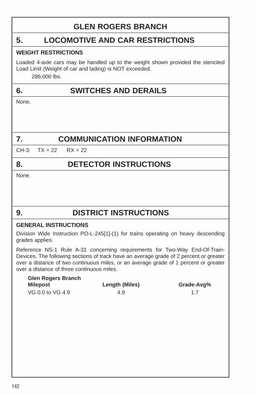
142
GLEN ROGERS BRANCH
5. LOCOMOTIVE AND CAR RESTRICTIONS
WEIGHT RESTRICTIONS
Loaded 4-axle cars may be handled up to the weight shown provided the stenciledLoad Limit (Weight of car and lading) is NOT exceeded.
286,000 lbs.
6. SWITCHES AND DERAILSNone.
7. COMMUNICATION INFORMATIONCH-3: TX = 22 RX = 22
8. DETECTOR INSTRUCTIONSNone.
9. DISTRICT INSTRUCTIONS
GENERAL INSTRUCTIONSDivision Wide Instruction PO-L-245[1]-(1) for trains operating on heavy descendinggrades applies.
Reference NS-1 Rule A-31 concerning requirements for Two-Way End-Of-Train-Devices. The following sections of track have an average grade of 2 percent or greaterover a distance of two continuous miles, or an average grade of 1 percent or greaterover a distance of three continuous miles.
Glen Rogers BranchMilepost Length (Miles) Grade-Avg%VG 0.0 to VG 4.9 4.9 1.7

143
VACO BRANCHWEST
�� SIDINGSIN FEET MP STATION NOTE
PD DISPATCHER ......................................................................
V 434.1/VC 0.0 VACO JCT.
VC 0.6 DEEPWATER
1. METHOD OF OPERATIONFrom To Tracks Signals AuthorityVaco Jct. Deepwater Main N/S TWCMP VC 0.0 MP VC 0.6
2. MAXIMUM SPEEDSMainTrack
Between MPHMP VC 0.0 and MP VC 0.6 10
3. CHECKING LOCOMOTIVE SPEED INDICATORTests for accuracy will be made at the following locations and Engineers will adjustspeed in accordance with any inaccuracy.
LOCATION OF TEST MILE SIGNS:None.
4. DIESEL UNIT RATINGSNone.
5. LOCOMOTIVE AND CAR RESTRICTIONS
WEIGHT RESTRICTIONS
Loaded 4-axle cars may be handled up to the weight shown provided the stenciledLoad Limit (Weight of car and lading) is NOT exceeded.
286,000 lbs.
CSXT
624
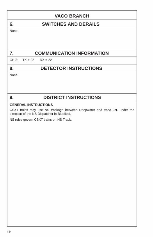
144
VACO BRANCH
6. SWITCHES AND DERAILSNone.
7. COMMUNICATION INFORMATIONCH-3: TX = 22 RX = 22
8. DETECTOR INSTRUCTIONSNone.
9. DISTRICT INSTRUCTIONS
GENERAL INSTRUCTIONSCSXT trains may use NS trackage between Deepwater and Vaco Jct. under thedirection of the NS Dispatcher in Bluefield.
NS rules govern CSXT trains on NS Track.
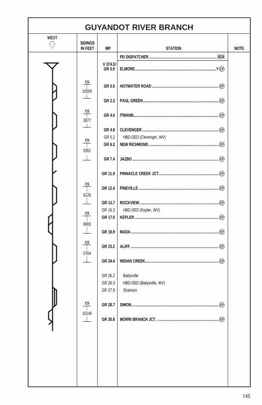
145
GUYANDOT RIVER BRANCHWEST
�� SIDINGSIN FEET MP STATION NOTE
PD DISPATCHER ......................................................................
V 374.5/GR 0.0 ELMORE....................................................................................Y
GR 0.5 HOTWATER ROAD .....................................................................
GR 2.3 PAUL GREEN ..............................................................................
GR 4.0 ITMANN........................................................................................
GR 4.8 CLEVENGER ...............................................................................
GR 5.2 HBD-DED (Clevenger, WV)
GR 6.2 NEW RICHMOND ........................................................................
GR 7.4 JAZBO .........................................................................................
GR 11.9 PINNACLE CREEK JCT..............................................................
GR 12.4 PINEVILLE ...................................................................................
GR 13.7 ROCKVIEW..................................................................................
GR 16.3 HBD-DED (Kepler, WV)
GR 17.0 KEPLER .......................................................................................
GR 18.9 MADA...........................................................................................
GR 23.2 ALIFF ...........................................................................................
GR 24.4 INDIAN CREEK............................................................................
GR 26.2 Bailysville
GR 26.3 HBD-DED (Bailysville, WV)
GR 27.9 Shannon
GR 28.7 SIMON..........................................................................................
GR 30.8 MORRI BRANCH JCT. . ..............................................................
10500
3877
5351
6126
9000
5764
10145
CP�
CP�
CP�
CP�
CP�
CP�
CP�
CP�
CP�
CP�
CP�
CP�
CP�
CP�
CP�
CP�
CS
CS
CS
CS
CS
CS
CS
624
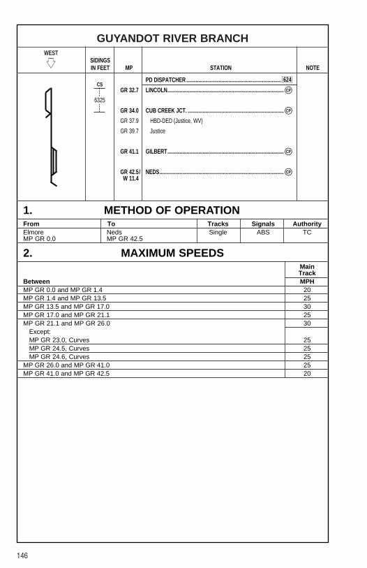
146
GUYANDOT RIVER BRANCHWEST
�� SIDINGSIN FEET MP STATION NOTE
PD DISPATCHER ......................................................................
GR 32.7 LINCOLN......................................................................................
GR 34.0 CUB CREEK JCT. .......................................................................
GR 37.9 HBD-DED (Justice, WV)
GR 39.7 Justice
GR 41.1 GILBERT......................................................................................
GR 42.5/ NEDS............................................................................................W 11.4
1. METHOD OF OPERATIONFrom To Tracks Signals AuthorityElmore Neds Single ABS TCMP GR 0.0 MP GR 42.5
2. MAXIMUM SPEEDSMainTrack
Between MPHMP GR 0.0 and MP GR 1.4 20MP GR 1.4 and MP GR 13.5 25MP GR 13.5 and MP GR 17.0 30MP GR 17.0 and MP GR 21.1 25MP GR 21.1 and MP GR 26.0 30
Except:MP GR 23.0, Curves 25MP GR 24.5, Curves 25MP GR 24.6, Curves 25
MP GR 26.0 and MP GR 41.0 25MP GR 41.0 and MP GR 42.5 20
CP�
CP�
CP�
CP�
6325
CS624
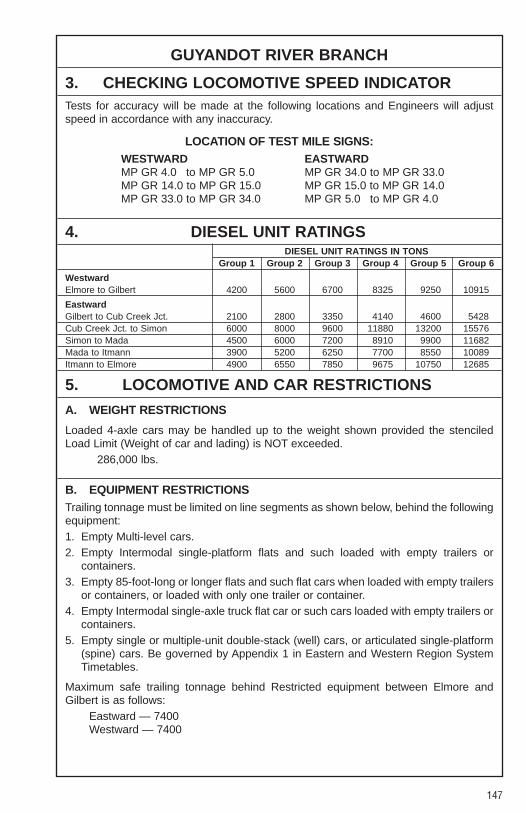
147
GUYANDOT RIVER BRANCH
3. CHECKING LOCOMOTIVE SPEED INDICATORTests for accuracy will be made at the following locations and Engineers will adjustspeed in accordance with any inaccuracy.
LOCATION OF TEST MILE SIGNS:WESTWARD EASTWARDMP GR 4.0 to MP GR 5.0 MP GR 34.0 to MP GR 33.0MP GR 14.0 to MP GR 15.0 MP GR 15.0 to MP GR 14.0MP GR 33.0 to MP GR 34.0 MP GR 5.0 to MP GR 4.0
4. DIESEL UNIT RATINGSDIESEL UNIT RATINGS IN TONS
Group 1 Group 2 Group 3 Group 4 Group 5 Group 6
WestwardElmore to Gilbert 4200 5600 6700 8325 9250 10915
EastwardGilbert to Cub Creek Jct. 2100 2800 3350 4140 4600 5428Cub Creek Jct. to Simon 6000 8000 9600 11880 13200 15576Simon to Mada 4500 6000 7200 8910 9900 11682Mada to Itmann 3900 5200 6250 7700 8550 10089Itmann to Elmore 4900 6550 7850 9675 10750 12685
5. LOCOMOTIVE AND CAR RESTRICTIONS
A. WEIGHT RESTRICTIONS
Loaded 4-axle cars may be handled up to the weight shown provided the stenciledLoad Limit (Weight of car and lading) is NOT exceeded.
286,000 lbs.
B. EQUIPMENT RESTRICTIONSTrailing tonnage must be limited on line segments as shown below, behind the followingequipment:1. Empty Multi-level cars.2. Empty Intermodal single-platform flats and such loaded with empty trailers or
containers.3. Empty 85-foot-long or longer flats and such flat cars when loaded with empty trailers
or containers, or loaded with only one trailer or container.4. Empty Intermodal single-axle truck flat car or such cars loaded with empty trailers or
containers.5. Empty single or multiple-unit double-stack (well) cars, or articulated single-platform
(spine) cars. Be governed by Appendix 1 in Eastern and Western Region SystemTimetables.
Maximum safe trailing tonnage behind Restricted equipment between Elmore andGilbert is as follows:
Eastward — 7400Westward — 7400
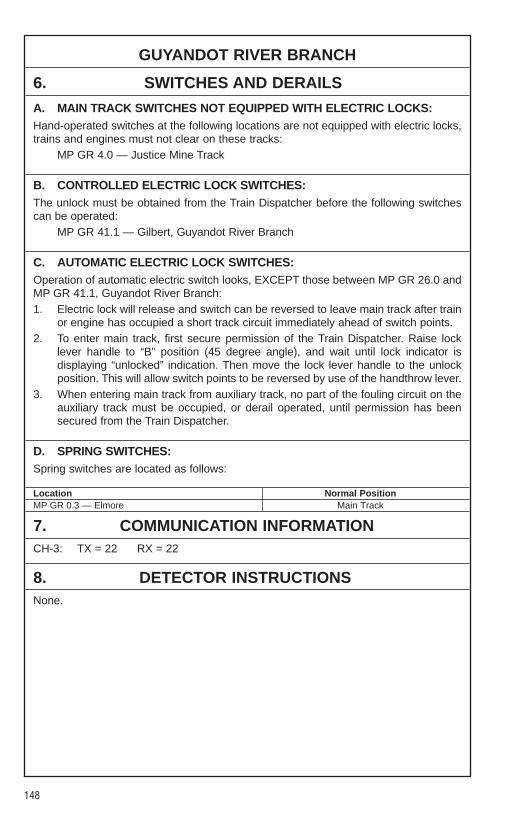
148
GUYANDOT RIVER BRANCH
6. SWITCHES AND DERAILS
A. MAIN TRACK SWITCHES NOT EQUIPPED WITH ELECTRIC LOCKS:Hand-operated switches at the following locations are not equipped with electric locks,trains and engines must not clear on these tracks:
MP GR 4.0 — Justice Mine Track
B. CONTROLLED ELECTRIC LOCK SWITCHES:The unlock must be obtained from the Train Dispatcher before the following switchescan be operated:
MP GR 41.1 — Gilbert, Guyandot River Branch
C. AUTOMATIC ELECTRIC LOCK SWITCHES:Operation of automatic electric switch looks, EXCEPT those between MP GR 26.0 andMP GR 41.1, Guyandot River Branch:1. Electric lock will release and switch can be reversed to leave main track after train
or engine has occupied a short track circuit immediately ahead of switch points.2. To enter main track, first secure permission of the Train Dispatcher. Raise lock
lever handle to “B” position (45 degree angle), and wait until lock indicator isdisplaying “unlocked” indication. Then move the lock lever handle to the unlockposition. This will allow switch points to be reversed by use of the handthrow lever.
3. When entering main track from auxiliary track, no part of the fouling circuit on theauxiliary track must be occupied, or derail operated, until permission has beensecured from the Train Dispatcher.
D. SPRING SWITCHES:Spring switches are located as follows:
Location Normal PositionMP GR 0.3 — Elmore Main Track
7. COMMUNICATION INFORMATIONCH-3: TX = 22 RX = 22
8. DETECTOR INSTRUCTIONSNone.
149
GUYANDOT RIVER BRANCH
9. DISTRICT INSTRUCTIONS
GENERAL INSTRUCTIONSCSXT trains may use NS trackage between Gilbert and Pemberton under the directionof the NS Dispatcher in Bluefield. NS rules will govern CSXT trains on NS Track.
Flag protection must be provided when trains or engines are operated over Route 52Crossing, MP GR 44.0 + 2600 feet.
When approaching Kepler, crews are to stop short of Dwarf Signal and receivepermission from Train Dispatcher to enter line switch and derail for movement beforeproceeding. When leaving Kepler, crews must clear Dwarf Signal before restoringswitch and derail to normal position.

150
PINNACLE CREEK BRANCHWEST
�� SIDINGSIN FEET MP STATION NOTE
PD DISPATCHER ......................................................................
PC 2.6 GARY 50
PC 0.0/ PINNACLE CREEK JCT.GR 11.9
1. METHOD OF OPERATIONFrom To Tracks Signals AuthorityGary 50 Pinnacle Creek Jct. Main N/S TWCMP PC 2.6 MP PC 0.0
2. MAXIMUM SPEEDSMainTrack
Between MPHMP PC 2.6 and MP PC 0.0 15
3. CHECKING LOCOMOTIVE SPEED INDICATORTests for accuracy will be made at the following locations and Engineers will adjustspeed in accordance with any inaccuracy.
LOCATION OF TEST MILE SIGNS:None.
4. DIESEL UNIT RATINGSNone.
5. LOCOMOTIVE AND CAR RESTRICTIONS
WEIGHT RESTRICTIONS
Loaded 4-axle cars may be handled up to the weight shown provided the stenciledLoad Limit (Weight of car and lading) is NOT exceeded.
286,000 lbs.
624
GR BR.
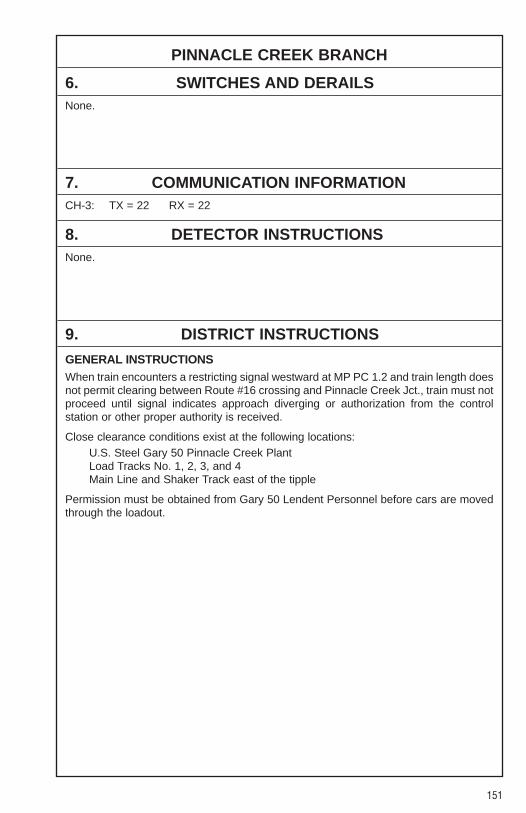
151
PINNACLE CREEK BRANCH
6. SWITCHES AND DERAILSNone.
7. COMMUNICATION INFORMATIONCH-3: TX = 22 RX = 22
8. DETECTOR INSTRUCTIONSNone.
9. DISTRICT INSTRUCTIONS
GENERAL INSTRUCTIONSWhen train encounters a restricting signal westward at MP PC 1.2 and train length doesnot permit clearing between Route #16 crossing and Pinnacle Creek Jct., train must notproceed until signal indicates approach diverging or authorization from the controlstation or other proper authority is received.
Close clearance conditions exist at the following locations:U.S. Steel Gary 50 Pinnacle Creek PlantLoad Tracks No. 1, 2, 3, and 4Main Line and Shaker Track east of the tipple
Permission must be obtained from Gary 50 Lendent Personnel before cars are movedthrough the loadout.
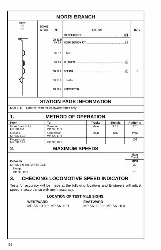
152
MORRI BRANCHWEST
�� SIDINGSIN FEET MP STATION NOTE
PD DISPATCHER ......................................................................
GR 30.8/SK 0.0 MORRI BRANCH JCT. ...............................................................
SK 5.2 Toler
SK 7.6 PLUNKETT ..................................................................................
SK 11.9 OCEANA ...................................................................................... 1
SK 16.0 Hatcher
SK 17.5 KOPPERSTON
STATION PAGE INFORMATIONNOTE 1: Control Point for eastward traffic only.
1. METHOD OF OPERATIONFrom To Tracks Signals AuthorityMorri Branch Jct. Oceana Main ABS TCMP SK 0.0 MP SK 11.9Oceana Kopperston Main N/S TWCMP SK 11.9 MP SK 17.5Kopperston 105MP SK 17.5 MP SK 19.5
2. MAXIMUM SPEEDSMainTrack
Between MPHMP SK 0.0 and MP SK 17.5 20
Except:MP SK 12.3 10
3. CHECKING LOCOMOTIVE SPEED INDICATORTests for accuracy will be made at the following locations and Engineers will adjustspeed in accordance with any inaccuracy.
LOCATION OF TEST MILE SIGNS:WESTWARD EASTWARDMP SK 10.0 to MP SK 11.0 MP SK 11.0 to MP SK 10.0
CP�
CP�
CP�
624
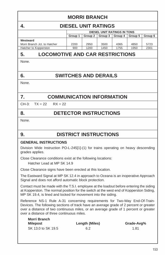
153
MORRI BRANCH
4. DIESEL UNIT RATINGSDIESEL UNIT RATINGS IN TONS
Group 1 Group 2 Group 3 Group 4 Group 5 Group 6
WestwardMorri Branch Jct. to Hatcher 2200 2950 3500 4365 4850 5723Hatcher to Kopperston 900 1200 1450 1755 1950 2301
5. LOCOMOTIVE AND CAR RESTRICTIONSNone.
6. SWITCHES AND DERAILSNone.
7. COMMUNICATION INFORMATIONCH-3: TX = 22 RX = 22
8. DETECTOR INSTRUCTIONSNone.
9. DISTRICT INSTRUCTIONS
GENERAL INSTRUCTIONSDivision Wide Instruction PO-L-245[1]-(1) for trains operating on heavy descendinggrades applies.
Close Clearance conditions exist at the following locations:Hatcher Lead at MP SK 14.9
Close Clearance signs have been erected at this location.
The Eastward Signal at MP SK 12.4 in approach to Oceana is an inoperative ApproachSignal and does not afford automatic block protection.
Contact must be made with the T.S.I. employee at the loadout before entering the sidingat Kopperston. The normal position for the switch at the west end of Kopperston Siding,MP SK 19.4, is lined and locked for movement into the siding.
Reference NS-1 Rule A-31 concerning requirements for Two-Way End-Of-Train-Devices. The following sections of track have an average grade of 2 percent or greaterover a distance of two continuous miles, or an average grade of 1 percent or greaterover a distance of three continuous miles.
Morri BranchMilepost Length (Miles) Grade-Avg%SK 13.0 to SK 19.5 6.2 1.81
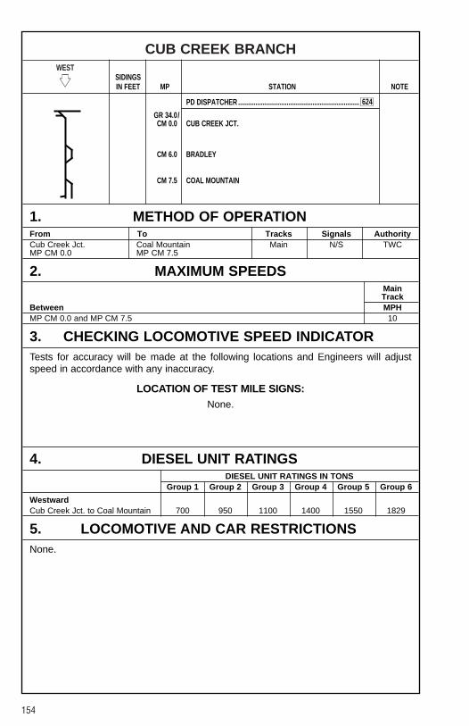
154
CUB CREEK BRANCHWEST
�� SIDINGSIN FEET MP STATION NOTE
PD DISPATCHER ......................................................................
GR 34.0/CM 0.0 CUB CREEK JCT.
CM 6.0 BRADLEY
CM 7.5 COAL MOUNTAIN
1. METHOD OF OPERATIONFrom To Tracks Signals AuthorityCub Creek Jct. Coal Mountain Main N/S TWCMP CM 0.0 MP CM 7.5
2. MAXIMUM SPEEDSMainTrack
Between MPHMP CM 0.0 and MP CM 7.5 10
3. CHECKING LOCOMOTIVE SPEED INDICATORTests for accuracy will be made at the following locations and Engineers will adjustspeed in accordance with any inaccuracy.
LOCATION OF TEST MILE SIGNS:None.
4. DIESEL UNIT RATINGSDIESEL UNIT RATINGS IN TONS
Group 1 Group 2 Group 3 Group 4 Group 5 Group 6
WestwardCub Creek Jct. to Coal Mountain 700 950 1100 1400 1550 1829
5. LOCOMOTIVE AND CAR RESTRICTIONSNone.
624
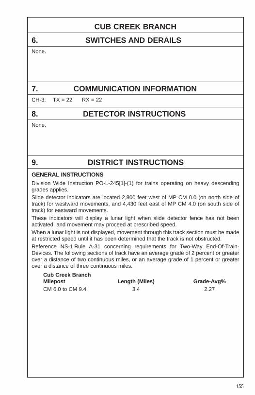
155
CUB CREEK BRANCH
6. SWITCHES AND DERAILSNone.
7. COMMUNICATION INFORMATIONCH-3: TX = 22 RX = 22
8. DETECTOR INSTRUCTIONSNone.
9. DISTRICT INSTRUCTIONS
GENERAL INSTRUCTIONSDivision Wide Instruction PO-L-245[1]-(1) for trains operating on heavy descendinggrades applies.Slide detector indicators are located 2,800 feet west of MP CM 0.0 (on north side oftrack) for westward movements, and 4,430 feet east of MP CM 4.0 (on south side oftrack) for eastward movements.These indicators will display a lunar light when slide detector fence has not beenactivated, and movement may proceed at prescribed speed.When a lunar light is not displayed, movement through this track section must be madeat restricted speed until it has been determined that the track is not obstructed.Reference NS-1 Rule A-31 concerning requirements for Two-Way End-Of-Train-Devices. The following sections of track have an average grade of 2 percent or greaterover a distance of two continuous miles, or an average grade of 1 percent or greaterover a distance of three continuous miles.
Cub Creek BranchMilepost Length (Miles) Grade-Avg%CM 6.0 to CM 9.4 3.4 2.27
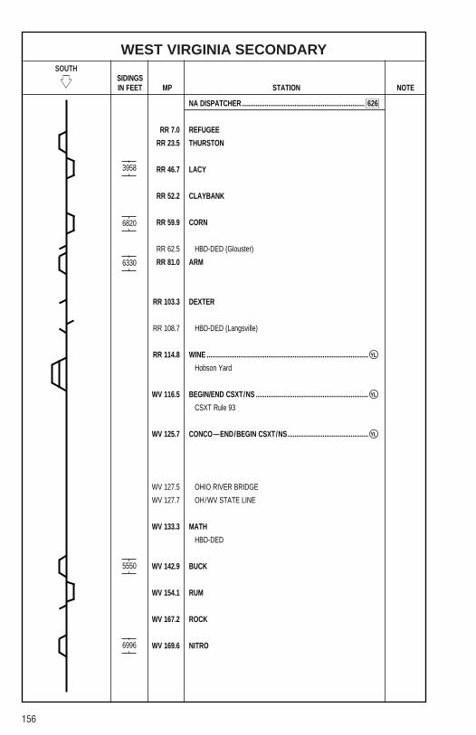
156
WEST VIRGINIA SECONDARYSOUTH
�� SIDINGSIN FEET MP STATION NOTE
NA DISPATCHER......................................................................
RR 7.0 REFUGEE
RR 23.5 THURSTON
RR 46.7 LACY
RR 52.2 CLAYBANK
RR 59.9 CORN
RR 62.5 HBD-DED (Glouster)
RR 81.0 ARM
RR 103.3 DEXTER
RR 108.7 HBD-DED (Langsville)
RR 114.8 WINE ............................................................................................
Hobson Yard
WV 116.5 BEGIN/END CSXT/NS ................................................................
CSXT Rule 93
WV 125.7 CONCO—END/BEGIN CSXT/NS..............................................
WV 127.5 OHIO RIVER BRIDGE
WV 127.7 OH/WV STATE LINE
WV 133.3 MATH
HBD-DED
WV 142.9 BUCK
WV 154.1 RUM
WV 167.2 ROCK
WV 169.6 NITRO
3958
6820
6330
5550
6996
YL�
YL�
YL�
626

157
WEST VIRGINIA SECONDARYSOUTH
�� SIDINGSIN FEET MP STATION NOTE
NA DISPATCHER......................................................................
WV 171.8 KAPOK
HBD-DED
WV 175.5 INSTITUTE
WV 182.2 STATE
WV 189.9 HBD-DED (Port Amherst)
WV 192.0 LEVI
WV 197.1 MAX.............................................................................................. 2
WV 198.8 Dickinson Yard
WV 200.1 DICK............................................................................................. 2
WV 203.5 Cedar Grove 1
WV 212.2 SMIT
WV 214.6 CHURCH ......................................................................................
Alloy Yard
WV 216.4 ALLOY ......................................................................................... 3
WV 220.0 FERRIS
WV 222.7 GAUL
WV 227.6 Vaughan Railroad
WV 228.2 CHAM
WV 242.2 LOCKWOOD
WV 246.9 JONES
WV 252.5 ENON
STATION PAGE INFORMATIONNOTE 1: All train and engines must approach Hughes Road Crossing, MP WV 207.4, not
exceeding 10 MPH until the leading end of the movement occupies the crossing.NOTE 2: The Yard Limits between Max and Dick are controlled by the Yardmaster at Dickinson.NOTE 3: The NA Dispatcher is in charge of the Yard Limits at Hobson and Alloy.
11088
YL�
YL�
YL�
YL�
7392
2700
JCT.
JCT.
626

158
WEST VIRGINIA SECONDARY
1. METHOD OF OPERATIONFrom To Tracks Signals AuthorityBannon Wine Main N/S TWCMP RR 0.0 MP RR 114.8Wine End NS Main N/S YLMP RR 114.8 MP RR 116.5Begin CSXT Conco Main N/S CSXTMP RR 116.5 MP WV 125.7 Rule 93Conco Max Main N/S TWCMP WV 125.7 MP WV 197.1Max Dick Main N/S YLMP WV 197.1 MP WV 200.1Dick Church Main N/S TWCMP WV 200.1 MP WV 214.6Church Alloy Main N/S YLMP WV 214.6 MP WV 216.4Alloy Enon Main N/S TWCMP WV 216.4 MP WV 252.5
2. MAXIMUM SPEEDSMainTrack
Between MPHMP RR 0.0 and MP RR 47.0 40
Except:MP RR 31.1 to MP RR 32.7 35MP RR 35.3 to MP RR 35.8 30MP RR 47.0, Through Turnout 25
MP RR 47.0 and MP RR 114.8 35Except:MP RR 53.3 to MP RR 55.5 30MP RR 59.5 to MP RR 73.0 30MP RR 79.6 to MP RR 88.2 30MP RR 88.2 to MP RR 88.4 25MP RR 88.4 to MP RR 103.6 30
Yard Limits:MP RR 114.8 to MP RR 116.4 — Restricted Speed 15
CSXT Yard Limits Rule 93:MP RR 116.4 to MP WV 125.7 — Controlled Speed 20
MP WV 125.7 and MP WV 216.4 40Except:MP WV 125.7 to MP WV 127.8 30MP WV 139.0 to MP WV 142.3 25MP WV 159.6 to MP WV 159.8 30MP WV 166.1 to MP WV 166.3 30MP WV 184.3 to MP WV 185.0 15MP WV 190.9 to MP WV 191.1 30MP WV 197.8, Through Turnout 25
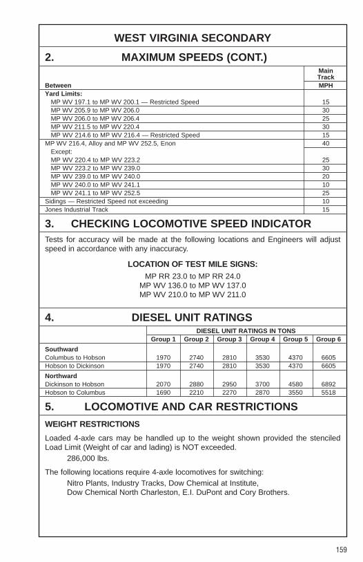
159
WEST VIRGINIA SECONDARY
2. MAXIMUM SPEEDS (CONT.)MainTrack
Between MPHYard Limits:
MP WV 197.1 to MP WV 200.1 — Restricted Speed 15MP WV 205.9 to MP WV 206.0 30MP WV 206.0 to MP WV 206.4 25MP WV 211.5 to MP WV 220.4 30MP WV 214.6 to MP WV 216.4 — Restricted Speed 15
MP WV 216.4, Alloy and MP WV 252.5, Enon 40Except:MP WV 220.4 to MP WV 223.2 25MP WV 223.2 to MP WV 239.0 30MP WV 239.0 to MP WV 240.0 20MP WV 240.0 to MP WV 241.1 10MP WV 241.1 to MP WV 252.5 25
Sidings — Restricted Speed not exceeding 10Jones Industrial Track 15
3. CHECKING LOCOMOTIVE SPEED INDICATORTests for accuracy will be made at the following locations and Engineers will adjustspeed in accordance with any inaccuracy.
LOCATION OF TEST MILE SIGNS:MP RR 23.0 to MP RR 24.0
MP WV 136.0 to MP WV 137.0MP WV 210.0 to MP WV 211.0
4. DIESEL UNIT RATINGSDIESEL UNIT RATINGS IN TONS
Group 1 Group 2 Group 3 Group 4 Group 5 Group 6
SouthwardColumbus to Hobson 1970 2740 2810 3530 4370 6605Hobson to Dickinson 1970 2740 2810 3530 4370 6605
NorthwardDickinson to Hobson 2070 2880 2950 3700 4580 6892Hobson to Columbus 1690 2210 2270 2870 3550 5518
5. LOCOMOTIVE AND CAR RESTRICTIONS
WEIGHT RESTRICTIONS
Loaded 4-axle cars may be handled up to the weight shown provided the stenciledLoad Limit (Weight of car and lading) is NOT exceeded.
286,000 lbs.
The following locations require 4-axle locomotives for switching:Nitro Plants, Industry Tracks, Dow Chemical at Institute, Dow Chemical North Charleston, E.I. DuPont and Cory Brothers.

160
WEST VIRGINIA SECONDARY
6. SWITCHES AND DERAILSSwitch Indicator: Arrow indicates the route for which the switch is lined:
MP WV 226.2 for switch at MP WV 227.6Green Arrow Proceed: Switch lined for Vaughan RailroadGreen Arrow Proceed: Switch lined for West Virginia Secondary Track
MP WV 245.8 for switch at MP WV 246.8
Green Arrow Proceed: Switch lined for Jones Industrial TrackGreen Arrow Proceed: Switch lined for West Virginia Secondary
7. COMMUNICATION INFORMATIONCH-2: TX = 64 RX = 64 CSXT BJ Dispatcher:
TX = 14 RX = 14 Tone 7
CYO 7-589-5622 Phone: 1-800-854-5694Phone: 1-800-898-4296 When on CSXT Dispatched TracksFax: 1-800-476-0147 Radio will monitor Ch. 8. If not equipped:
1-800-589-5757 TX = 64 RX = 64
8. DETECTOR INSTRUCTIONSNone.
9. DISTRICT INSTRUCTIONS
FREIGHT TRAIN HANDLING INSTRUCTIONSAll crews on duty at Hobson or Dickinson that will work between those two points musthave a CSXT Bulletin addressed to their train before leaving the terminal.
All mine job crews working at Power Mountain will contact the Dickinson Yardmaster byphone to determine the status of Terry Eagle coal operation before leaving.
All mine runs operating at Power Mountain or Fola will notify the Yardmaster the timewhen they arrive, when half of train has been loaded and completion of loading.
The switching crews are reminded that before tying up their job that they are to contactthe Yardmaster to insure that all paperwork has been processed and furtherinstructions. Also, the switchers will not block the passing siding at Institute withoutpermission from the NA Dispatcher.
NS trains may use the track between RQ 38.5 (New Lex ) and RQ 36 (Roseville) on theOCRR under the instructions and authority from the OCRR Dispatcher. NS OperatingRule 105 will govern movements on this track section.
Division Wide Instruction PO-L-245[1]-(1) for trains operating on heavy descendinggrades applies.
Reference NS-1 Rule A-31 concerning requirements for Two-Way End-Of-Train-Devices.
��
��
��
��
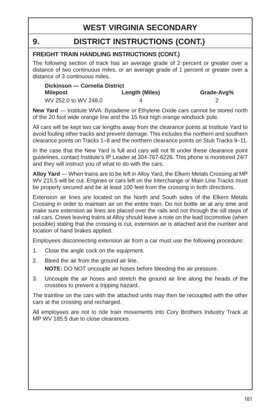
161
WEST VIRGINIA SECONDARY
9. DISTRICT INSTRUCTIONS (CONT.)
FREIGHT TRAIN HANDLING INSTRUCTIONS (CONT.)The following section of track has an average grade of 2 percent or greater over adistance of two continuous miles, or an average grade of 1 percent or greater over adistance of 3 continuous miles.
Dickinson — Cornelia DistrictMilepost Length (Miles) Grade-Avg%WV 252.0 to WV 248.0 4 2
New Yard — Institute WVA: Bytadiene or Ethylene Oxide cars cannot be stored northof the 20 foot wide orange line and the 15 foot high orange windsock pole.
All cars will be kept two car lengths away from the clearance points at Institute Yard toavoid fouling other tracks and prevent damage. This includes the northern and southernclearance points on Tracks 1–8 and the northern clearance points on Stub Tracks 9–11.
In the case that the New Yard is full and cars will not fit under these clearance pointguidelines, contact Institute’s IP Leader at 304-767-6226. This phone is monitored 24/7and they will instruct you of what to do with the cars.
Alloy Yard — When trains are to be left in Alloy Yard, the Elkem Metals Crossing at MPWV 215.5 will be cut. Engines or cars left on the Interchange or Main Line Tracks mustbe properly secured and be at least 100 feet from the crossing in both directions.
Extension air lines are located on the North and South sides of the Elkem MetalsCrossing in order to maintain air on the entire train. Do not bottle air at any time andmake sure extension air lines are placed over the rails and not through the sill steps ofrail cars. Crews leaving trains at Alloy should leave a note on the lead locomotive (whenpossible) stating that the crossing is cut, extension air is attached and the number andlocation of hand brakes applied.
Employees disconnecting extension air from a car must use the following procedure:
1. Close the angle cock on the equipment.
2. Bleed the air from the ground air line.NOTE: DO NOT uncouple air hoses before bleeding the air pressure.
3. Uncouple the air hoses and stretch the ground air line along the heads of thecrossties to prevent a tripping hazard.
The trainline on the cars with the attached units may then be recoupled with the othercars at the crossing and recharged.
All employees are not to ride train movements into Cory Brothers Industry Track atMP WV 185.5 due to close clearances.
162
POCAHONTAS DIVISION SPECIAL INSTRUCTIONS
TABLE OF CONTENTS
Page
PO-GR-10-1. Bulletins..........................................................................................163PO-GR-16-1. Ground Air ......................................................................................163PO-GR-16-2. Air Hoses........................................................................................163PO-GR-21-1. Locomotive Seating ......................................................................163PO-GR-32-1. Excessive Dimension Equipment ..................................................164PO-GR-32-2. Train Consist ..................................................................................164PO-L-1. Unusual Or Suspicious Activity ......................................................165PO-L-238-1. Fuel Conservation..........................................................................165PO-L-242-1. Shoving Movements ......................................................................165PO-L-245[1]-(1). Train Handling................................................................................166PO-L-248-1. Pusher Service ..............................................................................167PO-M-1. Close Clearances ..........................................................................167PO-S1040-1. Personal Protective Equipment ....................................................167PO-S1043-1. Eye Protection................................................................................167PO-SR1070-1. 3 Point Contact ..............................................................................168PO-34-1. Track Designation ..........................................................................168PO-103(b)-1. Riding Cars ....................................................................................168PO-103(c)-1. Running Switch ..............................................................................168PO-103(d)-1. Car Securement ............................................................................168PO-103(e)-1. Double Check Switch ....................................................................168PO-103(e)-2. Safety Stop ....................................................................................168PO-245-1. Non-Signaled Tracks......................................................................169PO-581-1. Caboose Instructions ....................................................................169PO-581-2. Train Responsibility........................................................................169PO-585-1. CYO — Centralized Yard Operations....................................169–170PO-585-2. Car Movement Documentation ......................................................171PO-601-1. Engine Occupancy ........................................................................171PO-601-3. Engine Movements ........................................................................171PO-630-1. Accelerated Conductor Trainees ..................................................172

163
POCAHONTAS DIVISION
SPECIAL INSTRUCTIONSPO-GR-10-1. BULLETINS
All Pocahontas Division Operations Bulletins and Superintendent Notices areelectrically posted in a bulletin board in the MEMO System. A Pocahontas Divisionmaster bulletin board “POBULLS” can be accessed which will contain separate bulletinboards for Operations Bulletins “POOPB” and Superintendent Notices “POGIB”.
All bulletins may be printed for your retention and future reference, but once a bulletinhas expired or has been cancelled or superceded, all copies must be destroyed.
Each employee, before commencing a trip or tour of duty, must read all Operationsbulletins applicable to his/her run that were posted since he/she last worked.In the event that the MEMO System is down, the Chief Dispatcher’s Office (7-926-4239or 304 325-4239) must be promptly contacted to secure bulletin information.
Whenever a Dispatcher’s Bulletin is received and the “time issued” on the Bulletin isgreater than 3 hours prior to the reporting time of the train, the Dispatcher’s Bulletinmust be verified with the Train Dispatcher on duty to ensure that their Bulletin is themost current.
PO-GR-16-1. GROUND AIR
Ground air systems at Norton, Andover, Carbo, Auville and Flat Top are equipped withself-venting cut off valves, which will allow air to vent from the hose after valve is closed.Air hoses may be separated after pressure has vented. If valve does not vent, allow 2minutes for pressure equalization before separating hose.
At Alfredon, the ground air hoses at the end of the yard are equipped with self-ventingcut off valves. The ground air hoses at the MIddle Road Crossing are equipped with amanual bleed valve on the hose gladhand which must be used to relieve air pressurefrom the hose after turning angle cocks and before uncoupling ground air from the trainline.
Transportation Department employees removing ground air from cars and trains atWeller, VA, will allow 2 minutes after closing both the angle cock and ground air cut-outcock for pressure equalization (bleeding) in the ground air line before separatinggladhands. The Weller ground air system (is not) equipped with self venting cut offvalves.
PO-GR-16-2. AIR HOSES
The practice of placing yard air hoses through the sill step of cars connected to yard airis prohibited. Yard air hoses once connected to the car will be draped over the rail 5–10feet in front of the car wheel in such a manner that the hose will be severed if the carsbegin to roll.
PO-GR-21-1. LOCOMOTIVE SEATING
When occupying locomotive cab, there must be sufficient seating for all employees.Locomotive cab seats shall be securely mounted and braced. No improvised ortemporary seating will be permitted.
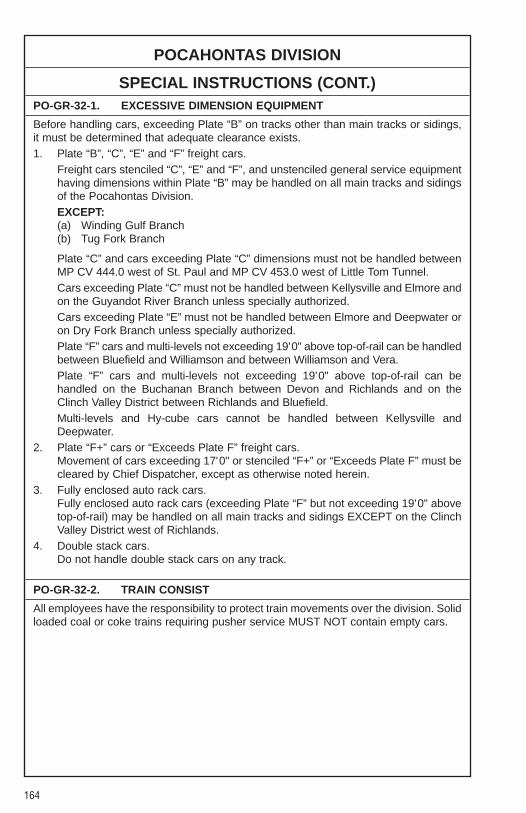
164
POCAHONTAS DIVISION
SPECIAL INSTRUCTIONS (CONT.)PO-GR-32-1. EXCESSIVE DIMENSION EQUIPMENT
Before handling cars, exceeding Plate “B” on tracks other than main tracks or sidings,it must be determined that adequate clearance exists.1. Plate “B”, “C”, “E” and “F” freight cars.
Freight cars stenciled “C”, “E” and “F”, and unstenciled general service equipmenthaving dimensions within Plate “B” may be handled on all main tracks and sidingsof the Pocahontas Division.EXCEPT:(a) Winding Gulf Branch(b) Tug Fork Branch
Plate “C” and cars exceeding Plate “C” dimensions must not be handled betweenMP CV 444.0 west of St. Paul and MP CV 453.0 west of Little Tom Tunnel.Cars exceeding Plate “C” must not be handled between Kellysville and Elmore andon the Guyandot River Branch unless specially authorized.Cars exceeding Plate “E” must not be handled between Elmore and Deepwater oron Dry Fork Branch unless specially authorized.Plate “F” cars and multi-levels not exceeding 19'0" above top-of-rail can be handledbetween Bluefield and Williamson and between Williamson and Vera.Plate “F” cars and multi-levels not exceeding 19'0" above top-of-rail can behandled on the Buchanan Branch between Devon and Richlands and on theClinch Valley District between Richlands and Bluefield.Multi-levels and Hy-cube cars cannot be handled between Kellysville andDeepwater.
2. Plate “F+” cars or “Exceeds Plate F” freight cars.Movement of cars exceeding 17'0" or stenciled “F+” or “Exceeds Plate F” must becleared by Chief Dispatcher, except as otherwise noted herein.
3. Fully enclosed auto rack cars.Fully enclosed auto rack cars (exceeding Plate “F” but not exceeding 19'0" abovetop-of-rail) may be handled on all main tracks and sidings EXCEPT on the ClinchValley District west of Richlands.
4. Double stack cars.Do not handle double stack cars on any track.
PO-GR-32-2. TRAIN CONSIST
All employees have the responsibility to protect train movements over the division. Solidloaded coal or coke trains requiring pusher service MUST NOT contain empty cars.
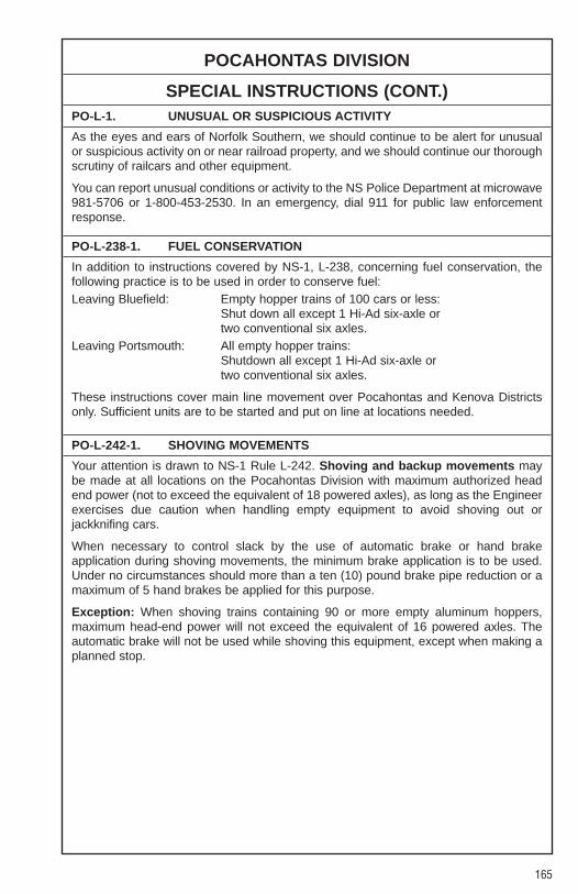
165
POCAHONTAS DIVISION
SPECIAL INSTRUCTIONS (CONT.)PO-L-1. UNUSUAL OR SUSPICIOUS ACTIVITY
As the eyes and ears of Norfolk Southern, we should continue to be alert for unusualor suspicious activity on or near railroad property, and we should continue our thoroughscrutiny of railcars and other equipment.
You can report unusual conditions or activity to the NS Police Department at microwave981-5706 or 1-800-453-2530. In an emergency, dial 911 for public law enforcementresponse.
PO-L-238-1. FUEL CONSERVATION
In addition to instructions covered by NS-1, L-238, concerning fuel conservation, thefollowing practice is to be used in order to conserve fuel:Leaving Bluefield: Empty hopper trains of 100 cars or less:
Shut down all except 1 Hi-Ad six-axle or two conventional six axles.
Leaving Portsmouth: All empty hopper trains:Shutdown all except 1 Hi-Ad six-axle or two conventional six axles.
These instructions cover main line movement over Pocahontas and Kenova Districtsonly. Sufficient units are to be started and put on line at locations needed.
PO-L-242-1. SHOVING MOVEMENTS
Your attention is drawn to NS-1 Rule L-242. Shoving and backup movements maybe made at all locations on the Pocahontas Division with maximum authorized headend power (not to exceed the equivalent of 18 powered axles), as long as the Engineerexercises due caution when handling empty equipment to avoid shoving out orjackknifing cars.
When necessary to control slack by the use of automatic brake or hand brakeapplication during shoving movements, the minimum brake application is to be used.Under no circumstances should more than a ten (10) pound brake pipe reduction or amaximum of 5 hand brakes be applied for this purpose.
Exception: When shoving trains containing 90 or more empty aluminum hoppers,maximum head-end power will not exceed the equivalent of 16 powered axles. Theautomatic brake will not be used while shoving this equipment, except when making aplanned stop.

166
POCAHONTAS DIVISION
SPECIAL INSTRUCTIONS (CONT.)PO-L-245[1]-(1). TRAIN HANDLING
Train Operating instructions on Heavy Descending GradesThese instructions apply to the following Branch Line segments on the PocahontasDivision where trains are initially assembled:
Prior to descending grade at any of the above locations, a brake test must be made inaccordance with NS-1 Rules A-6 or A-14. When inspection is completed and prior todeparting, Engineer will recharge air brake system to within 15 PSI of Feed ValveSetting for five minutes as indicated on the rear of the train.
At locations where independent brakes will not hold a train, a sufficient number of handbrakes must be applied to secure train while air brake system is being charged.
When air brakes have released, a signal will be given to the Engineer to apply a holdingbrake (a holding brake is a brake service reduction sufficient to hold train while handbrakes are being released).
When ready to depart, Engineer will release independent brake and apply power, ifnecessary. As soon as the train begins to move, Engineer must apply full dynamic brakeand make a sufficient air brake application to control speed of train.
Any time a freight train is descending a heavy grade and automatic brake application isrequired to control speed of train, should the equalizing reservoir pressure be reducedto 65 PSI (70 PSI when carrying 100 PSI feed valve setting) on lead locomotive, thetrain must be stopped immediately, sufficient hand brakes applied to hold train on gradeand air brakes system recharged before proceeding downgrade.
When air brakes have released, a signal will be given to the Engineer to apply a holdingbrake (a holding brake is a brake service reduction sufficient to hold train while handbrakes are being released).
Beard’s Fork BranchBeech Fork SpurBenedict SpurBig Creek BranchBig Prater Creek SpurBolt BranchBriar Mountain BranchBuchanan BranchBuzzard’s Creek BranchCaretta BranchCedar BranchCoal Creek BranchCub Creek BranchDelorme BranchDumps Creek BranchFolaFour Pole SpurGlen Rogers BranchHurricane BranchJamboree SpurLaurel Fork SpurLenore BranchLick Fork Branch
Long Fork SpurMarrowbone BranchMayflower SpurMorri BranchNolan SpurNorth Fork BranchPardee BranchPine BranchPower MountainRight Fork of Garden Creek SpurRoda BranchSand Lick BranchSouth Fork BranchSpice Creek BranchStone Coal BranchSycamore BranchTrack “C” Mate Creek BranchTug Fork BranchUpper Elk Creek SpurWentzWhite Oak BranchWinding Gulf Branch
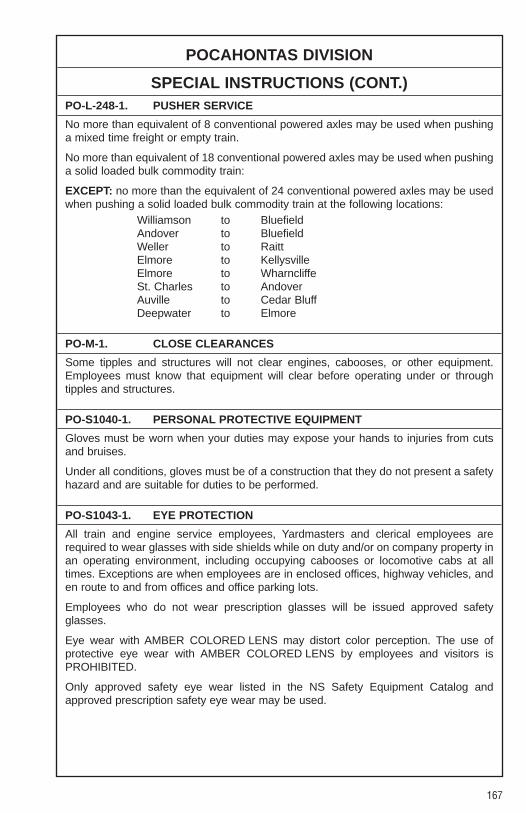
167
POCAHONTAS DIVISION
SPECIAL INSTRUCTIONS (CONT.)PO-L-248-1. PUSHER SERVICE
No more than equivalent of 8 conventional powered axles may be used when pushinga mixed time freight or empty train.
No more than equivalent of 18 conventional powered axles may be used when pushinga solid loaded bulk commodity train:
EXCEPT: no more than the equivalent of 24 conventional powered axles may be usedwhen pushing a solid loaded bulk commodity train at the following locations:
Williamson to BluefieldAndover to BluefieldWeller to RaittElmore to KellysvilleElmore to WharncliffeSt. Charles to AndoverAuville to Cedar BluffDeepwater to Elmore
PO-M-1. CLOSE CLEARANCES
Some tipples and structures will not clear engines, cabooses, or other equipment.Employees must know that equipment will clear before operating under or throughtipples and structures.
PO-S1040-1. PERSONAL PROTECTIVE EQUIPMENT
Gloves must be worn when your duties may expose your hands to injuries from cutsand bruises.
Under all conditions, gloves must be of a construction that they do not present a safetyhazard and are suitable for duties to be performed.
PO-S1043-1. EYE PROTECTION
All train and engine service employees, Yardmasters and clerical employees arerequired to wear glasses with side shields while on duty and/or on company property inan operating environment, including occupying cabooses or locomotive cabs at alltimes. Exceptions are when employees are in enclosed offices, highway vehicles, anden route to and from offices and office parking lots.
Employees who do not wear prescription glasses will be issued approved safetyglasses.
Eye wear with AMBER COLORED LENS may distort color perception. The use ofprotective eye wear with AMBER COLORED LENS by employees and visitors isPROHIBITED.
Only approved safety eye wear listed in the NS Safety Equipment Catalog andapproved prescription safety eye wear may be used.

168
POCAHONTAS DIVISION
SPECIAL INSTRUCTIONS (CONT.)PO-SR1070-1. 3 POINT CONTACT
Your attention is directed to SR1070 and SR1071 getting on or off equipment.Employees must maintain 3 point contact when mounting, dismounting or moving aboutequipment. Employees must incorporate “buddy system” when possible when handlingmaterial or personal items on or off equipment.
PO-34-1. TRACK DESIGNATION
In Traffic Control territory, where two main tracks are in service, the track to the rightas viewed by a westward train is Main 2, and the track to the left is Main 1.
PO-103(b)-1. RIDING CARS
Employees will not ride the leading end of a car, when it places the employees betweenthe gauge of the track except when it is necessary to operate the hand brake on amoving car not coupled to a locomotive. This does not prohibit an employee from ridingunder the slope sheets of a hopper or covered hopper on an extended shovemovement.
PO-103(c)-1. RUNNING SWITCH
Locations where running switches are authorized: none.
PO-103(d)-1. CAR SECUREMENT
Unless specifically authorized by Trainmaster’s Bulletin, cars or engines left on anytrack must be left as follows:1. Single-end tracks — no less than one (1) car length from end of track (dirt mound,
bumping post, wheel stops).2. Tracks open on either end — no less than one (1) car length from derail, if so
equipped, or clearance point on either end.
PO-103(e)-1. DOUBLE CHECK SWITCH
When engaged in switching operations, clear communication between groundmen andEngineers about the position of switches and/or derail must be ascertained.When the switch and/or derail has been aligned properly, the groundman willcommunicate the position of switch and/or derail to the Engineer. It is the Engineer’sresponsibility to repeat the positions and ask for the groundman to double check theswitch and/or derail, even if groundman originally stated “double checked”.The groundman will inspect the switch and/or derail position and inform the Engineerthat they have been double checked. After confirming double check with thegroundman, then the Engineer may proceed with moves in accordance with OperatingRule 508.
PO-103(e)-2. SAFETY STOP
When practical for safe handling of equipment, plan a safety stop one car prior tocoupling to cars positioned within 50 feet of derails, wheel stops or cars that have apotential of roll out.

169
POCAHONTAS DIVISION
SPECIAL INSTRUCTIONS (CONT.)PO-245-1. NON-SIGNALED TRACKS
The display of a proceed aspect governing movement on to non-signaled branches,spurs or other tracks does not convey authority beyond the opposing home signal ofthe interlocking. Trains or engines must have the necessary prescribed authority beforeproceeding onto non-signaled territory (Track Warrant, Rule 105 or Rule 93).
PO-581-1. CABOOSE INSTRUCTIONS
All employees are prohibited from lighting caboose heaters/stoves equipped withpropane gas. Propane heaters/stoves must be lit by mechanical personnel.
Cabooses equipped with diesel/kerosene may be lit by employees followinginstructions posted on caboose wall. NOTE: If caboose is to be left for an extendedtime, turn the control valve to pilot “P” position.
PO-581-2. TRAIN RESPONSIBILITY
Industry personnel (including mine personnel) cannot perform work related to trains NScrews are operating. This includes, but is not limited to, setting or releasing handbrakes, making cuts, protecting shoves, dropping cars and handling switches andderails. Crews are to insure that industry personnel do not perform this work. Crewmembers may be transported by industry personnel in passenger type vehicles inaccordance with HV-1.
PO-585-1. CYO — CENTRALIZED YARD OPERATIONS
Road Freight & Road Locals1. Beginning of Road Trip
(a) Paperwork — At locations where a YM issues the paperwork, Conductor willattain paperwork from the YM and any instructions. At locations where CYOissues paperwork, Conductor will call CYO and attain paperwork from CYOand any instructions.
(b) Advance Paperwork — When known “line of road” pick ups are required,Conductor should attain the “Wheel Report” for the pick up from the YM orCYO clerk, whichever is applicable.
(c) Industry Work — All trains performing industry work, should receive the “WorkOrder” for the industry work to be performed. Either YM or CYO shouldprovide such documentation, whichever is applicable.
2. Picking Up on the Line of Road(a) CYO Notification — Conductor will “tone” CYO utilizing the radio. On portions
of the Division where the “tone” is not available, Conductor will notify CYOutilizing the ARN (7-589-5980) as soon as possible of the pick up.
(b) Information — Conductor will inform CYO of the cars picked up, detailing the“Head Car” and “Rear Car” of the pick up and the total number of cars pickedup, and where in the train the cars were picked up.
3. Setting Out on the Line of Road(a) CYO Notification — Conductor will “tone” CYO utilizing the radio. On portions
of the Division where the “tone” is not available, Conductor will notify CYOutilizing the ARN (7-589-5980) as soon as possible of the pick up.
(b) Information — Conductor will inform CYO of the cars set out detailing the“Head Car” and “Rear Car” of the set out and the total number of cars set out,and what track the cars were put in.
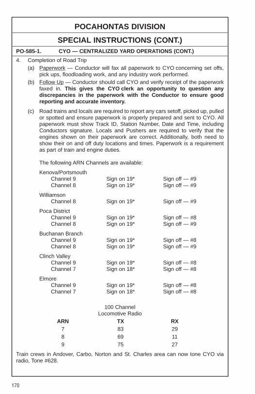
170
POCAHONTAS DIVISION
SPECIAL INSTRUCTIONS (CONT.)PO-585-1. CYO — CENTRALIZED YARD OPERATIONS (CONT.)
4. Completion of Road Trip(a) Paperwork — Conductor will fax all paperwork to CYO concerning set offs,
pick ups, floodloading work, and any industry work performed.(b) Follow Up — Conductor should call CYO and verify receipt of the paperwork
faxed in. This gives the CYO clerk an opportunity to question anydiscrepancies in the paperwork with the Conductor to ensure goodreporting and accurate inventory.
(c) Road trains and locals are required to report any cars setoff, picked up, pulledor spotted and ensure paperwork is properly prepared and sent to CYO. Allpaperwork must show Track ID, Station Number, Date and Time, includingConductors signature. Locals and Pushers are required to verify that theengines shown on their paperwork are correct. Additionally, both need toshow their on and off duty locations and times. Paperwork is a requirementas part of train and engine duties.
The following ARN Channels are available:
Kenova/PortsmouthChannel 9 Sign on 19* Sign off — #9Channel 8 Sign on 19* Sign off — #9
WilliamsonChannel 8 Sign on 19* Sign off — #9
Poca DistrictChannel 9 Sign on 19* Sign off — #8Channel 8 Sign on 19* Sign off — #9
Buchanan BranchChannel 9 Sign on 19* Sign off — #8Channel 8 Sign on 19* Sign off — #9
Clinch ValleyChannel 9 Sign on 19* Sign off — #8Channel 7 Sign on 18* Sign off — #8
ElmoreChannel 9 Sign on 19* Sign off — #8Channel 7 Sign on 18* Sign off — #8
100 ChannelLocomotive Radio
ARN TX RX7 83 298 69 119 75 27
Train crews in Andover, Carbo, Norton and St. Charles area can now tone CYO viaradio, Tone #628.
171
POCAHONTAS DIVISION
SPECIAL INSTRUCTIONS (CONT.)PO-585-2. CAR MOVEMENT DOCUMENTATION
Be governed by the following instructions regarding Car movement Documentation:1. Conductors are required to have “Proper Documentation” prior to moving a car,
loaded or empty. This documentation may be in the form of:(a) Waybill or Mine Tag.(b) Computer generated “Car Handle Report”.(c) Hand-written “Car Handle Report” (except Hazardous Material), then
Conductor must have waybill or forwarding instructions prepared by shipper,if hand-written “Car Handle Report” is used.
2. Conductors will be furnished a computer generated “Car Handle Report” instanding order from waybills/mine tags, when computer generated report is notavailable or feasible to furnish.
3. Shippers will furnish a separate mine tag or waybill (at mine) for each car exceptfor full “unit coal trains” i.e. 96 Scherer, 90 Wateree, which moves as a single unitfrom origin to destination.(a) These mine tags/waybills will be maintained in standing order of cars and
transferred from Conductor to Conductor, thus allowing each Conductor toprepare a hand-written “Car Handle Report” until:1. A computer generated car handling report can be furnished.2. Conductor is advised that cars he/she is handling are currently shown
located in the track/train he/she is handling, which case Conductor willfurnish head and rear car initial/number, track from which picked up, headand rear car number of each block set off, track and time each block isset off.
(b) Mine tags will be required for all Tidewater coal trains departing thePocahontas Division.
PO-601-1. ENGINE OCCUPANCY
When operating multiple unit locomotive consists without cars and/or cabooses coupledon any extended moves on line of road or within the terminal limits, the Engineer MUSToperate when practicable from the lead locomotive in the direction of movement. Anextended movement for these purposes is considered to be any movement, other thanswitching moves, which pass signals, pass over switches or public road crossings orinvolves any other movements in excess of 1/4 of mile on line of road.
PO-601-3. ENGINE MOVEMENTS
All pusher engineers must report their engine movements to CYO using the faxableforms available.
172
POCAHONTAS DIVISION
SPECIAL INSTRUCTIONS (CONT.)PO-630-1. ACCELERATED CONDUCTOR TRAINEES
Accelerated Conductor Trainees (ACT) working on the Pocahontas Division will bedistinguished by their “HUNTER ORANGE” caps which they are required to wear whileon duty in training.All employees are urged to assist these new employees and to properly train them inthe “safe” manner that all Norfolk Southern Employees should follow.These new employees are not to be used as a second or third switchman/trainman ona crew, and are not to perform any work, unless under direct supervision of anothercrew member.

NOTES
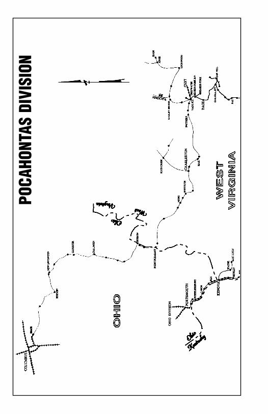
POCA
HONT
AS D
IVIS
ION
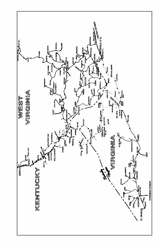

Our NS Goal-No Damage
N
ORFOLK SOUTHERN
Q
UALITY TRANSPORTATIO
N
GO FORFOUR