03.solutions to concepts0303.solutions to concepts.solutions to concepts
DESCRIPTION
03.Solutions to Co03.Solutions to Concepts03.Solutions to Concepts03.Solutions to Concepts03.S03.Solutions to Concepts03.Solutions to Concepts03.Solutions to Concepts03.Solutions to Conceptsolutions to ConceptsnceptsTRANSCRIPT

SMS-Controlled Door Lock
With Image Capture using Android Phone
A Design Project
Presented to the
Faculty of
The Electrical/Electronics and Communications
Engineering Department of the
University of San Carlos
Cebu City, Philippines
In Partial Fulfillment
Of the Requirements for the Degree
Bachelor of Science in Electronics
Engineering
By
Filomeno, Gil Maica Marie V.
Ledon, Michelle P.
Lenares, Prima Socorro L.
Baltazar Raffiñan, M. Eng
Adviser
Adrian Villarin, ECE
Co-Adviser
March 2014
i

v

Abstract
In this study, a door lock prototype system was designed which can be remotely accessed
by mobile devices through SMS. The aim of this study is to help homeowners monitor
their houses if there is a person at the doorstep and will alert the owner if there is a forced
entry. The prototype system was composed of the Arduino Mega ADK as the
microcontroller, Android phone as the transceiver which sends and receives the SMS
commands, Solenoid lock as the lock and Opto interrupter as the sensor for the intruder.
An Android application was built in which if all the components are integrated, the
system will function according to the commands requested by the homeowner where it
capture images of force entry person then sends it through MMS and notifies the
homeowner of the state of the lock after sending the lock command. The system’s
performance is analyzed by accessing the system, first sending commands and triggering
the doorbell and the alarm on the system at different places with different signal strength
in order to test how fast the system will respond. Data will be collected from the success
and failure of attempts by sending commands and receiving SMS and MMS.
ii

Approval Sheet
This Design Project entitled “SMS Controlled Door Lock With Image Capture Using Android Phone”, prepared and submitted by Filomeno, Gil Maica Marie V., Ledon, Michelle P. and Lenares, Prima Socorro L., in partial fulfillment of the requirements for the degree of Bachelor of Science in Electronics Engineering has been examined and is recommended for acceptance for Final Defense.
THESIS PROJECT COMMITTEE
Albert Bañacia, M’Eng. Chairman
Sheila Mae E. Jungco, ECE Jerome M. Puza, ECE Member Member
Balatzar Raffiñan, M’Eng. Adrian D. Villarin, ECE Adviser Adviser
PANEL OF ORAL EXAMINERSApproved by Thesis Project Committee with a grade of PASSED.
Albert Bañacia, M’Eng. Chairman
Sheila Mae E. Jungco, ECE Jerome M. Puza, ECE Member Member
Baltazar Raffiñan,M’Eng. Adrian D. Villarin, ECE Adviser Adviser
Accepted in partial fulfillment of the requirements for the degree of Bachelor of Science in Electronics Engineering.
March 5, 2014 Isabelo A. Rabuya, MSEEDate of Project Oral Defense Chairman, EE/ECE Department
ii

ACKNOWLEDGEMENT
Thesis Project is one of the most challenging courses of a college student. It needs team work, faith, trust and dedication in committing this task. This wouldn’t have been made possible without these people who have extended their help in making this project into a reality. We, therefore, would like to extend our profound gratitude to the following:
OUR BELOVED GOD THE FATHER, who is there guiding us in all the trials, for the good health, for enlightening our minds and giving us faith to accomplish this project.
ENGR. BALTAZAR RAFFIÑAN and ENGR. ADRIAN VILLARIN, our supportive advisers, who sincerely share to us the knowledge they knew and guiding and supervise in making this project.
ENGR. ALBERT BAÑACIA, ENGR. SHEILA MAE JUNGCO, AND ENGR. JEROME PUZA, our beloved panelists, who is there to critic our design and also share to us the ideas that may be helpful in obtaining this project.
EE/ECE FACULTY MEMBERS, who teach us the knowledge that is applicable in this project; they also inspire, encourage and instilled to us a positive attitude.
ANALOG DEVICES LABORATORY, SPECIAL APPLICATION LABORATORY AND CBELS, for the accommodation in making this project and allowing us to borrow and use the materials that is needed in making this project.
MINIONS and FRIENDS, who extend their help in finishing this project and for the joy and struggles we share.
OUR BELOVED PARENTS, for the financial support, inspiration to accomplish
this project and always there cheering.
Table of Contents
iii

Title Page i
Abstract ii
Approval Sheet iii
Acknowledgement iv
Tables of Contents v
List of Figures and Tables vi
Chapter 1 The Problem and Its Settings 1
1.1 Introduction1.2 Statement of the Problem1.3 Significance of the Study1.4 Scope and Limitations1.5 Definition of Terms
Chapter 2 Review of Related Literature 5
2.1 Remote Door Lock Project
2.2 Automatic Door Lock System
2.3 Security Intrusion Alert Method and Device
to Communicate via SMS
2.4 Design and Implementation of Home Security System Based
on Laser Trip Alarm with Webcam and GPRS Module Interface
2.5 SMS based Remote Control System
2.6 Wireless Sensor Network-Based Appliance Monitoring Using
STM32 Microcontroller and XBee Module via Android App (MAP)
Chapter 3 Methodology 9
iv
1.1 Project Flow1.2 Software Implementation1.3 Hardware Tools1.4 Hardware Implementation1.5 Testing1.6 Halfway Deliverables
Chapter 4 Results and Discussions
4.1 4.2 4.3 4.4 4.5
Chapter 5 Conclusions, and Recommendations
5.1 Conclusions 5.2 Recommendations
Bibliography
Appendices
Appendix A – Gantt Chart
Appendix B – Bill of Materials
Appendix C – Schematic Diagram and Layouts
Appendix D – Module Schematics
Appendix E – Datasheets
Appendix F – Microcontroller Unit Code
Appendix G – ‘Default.php’ Page Code
Appendix H – ‘Acceleration.php’ Page Code
Curriculum Vitae
List of Tables and Figures
v

Figures
Figure No. Name of Figure Page 3.1 Project Flow Chart
3.3.1 System Flow3.3.2 Intruder Alarm Flow Chart3.3.3 Command Received Flow Chart3.3.4 Doorbell Flow Chart
3.5 System Block Diagram
Tables
Table No. Name of the Table Page
vi
Chapter 1
The Problem and Its Settings
1.1 Introduction
The security of every home is a matter of great concern to everybody. Everyone
have a lot of things going on their everyday life. Each of them is busy with their own
life, problem, responsibilities, work, school and so on. Some are even busy that they tend
to forget the security threats that come to their premises. On average, in Manila, the
indices of people worrying about house break-ins and problems with property crimes are
about 69 percent from the year 2012 [1].
Security threats may come at a time when everyone least expect it, especially if
they forget the safety measures done when they leave their homes unattended.
There are solutions to decrease the worries and occurrences of the said crimes.
One method is to remotely monitor the property with the use of 2G technologies. 2G
technologies enable the various mobile phone networks to provide the services such as
text messages and MMS (multimedia messages) [2]. With the use of this technology, it
will help provide real-time communication with the system and the user, where the user
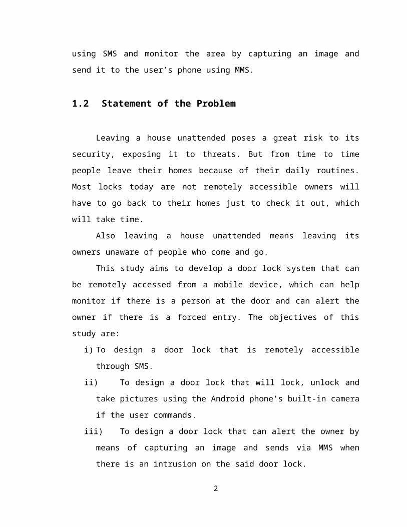
can remotely control the system using SMS and monitor the area by capturing an image
and send it to the user’s phone using MMS.
1.2 Statement of the Problem
Leaving a house unattended poses a great risk to its security, exposing it to
threats. But from time to time people leave their homes because of their daily routines.
Most locks today are not remotely accessible owners will have to go back to their homes
just to check it out, which will take time.
Also leaving a house unattended means leaving its owners unaware of people who
come and go.
1
This study aims to develop a door lock system that can be remotely accessed from
a mobile device, which can help monitor if there is a person at the door and can alert the
owner if there is a forced entry. The objectives of this study are:
i) To design a door lock that is remotely accessible through SMS.
ii) To design a door lock that will lock, unlock and take pictures using the Android
phone’s built-in camera if the user commands.
iii) To design a door lock that can alert the owner by means of capturing an image
and sends via MMS when there is an intrusion on the said door lock.
iv) To make use of the Android operated Smartphone as the GSM Module that will
interface with the microcontroller.
1.3 Significance of the Study
The project is designed to improve monitoring and security of households. This
project allows homeowners to be more vigilant of the events that may occur. The project
will provide homeowners peace of mind, safety and ease through the use of technology.
They also have easy access and less time consumed on following up with their home
security. They can access and monitor their front door locks remotely through the use of a
mobile device via SMS and can take pictures of the person who is currently at their
doorstep.
This project will also be useful for a private owned home/house that cannot afford
to hire security personnel, people who are always in a hurry and in the midst of an
emergency. In general, the people who are concerned about the security of their property
will benefit from this project because of the remote accessibility of the door lock and
image capturing feature.
The outcome of this project study may also be used as reference by the ECE/EE
students in their future studies concerning home automation and security using wireless
technology.
2

1.4 Scope and Limitations
The study will focus on designing a door lock system that can be accessed
remotely through a cellular phone.
The door lock system will consist of the following: microcontroller, an Android
operated Smartphone, door lock circuit, doorbell and the users’ mobile phone. An
Arduino Mega ADK board will be used as the microcontroller which is only compatible
for Android phone versions 2.3 and above. This board will be programmed using C or C+
+ programming language and a Java programming language for the Android phone.
The Android Phone, which is connected with the microcontroller, will receive the
commands from the users through a mobile phone, which are to LOCK, UNLOCK and
TAKE A PICTURE. The Android phone will be used to capture an image and send it
using MMS to the users’ phone. Only one image will be captured in every command
“TAKE A PICTURE” and when an intrusion occurs. The captured image will be limited
to the viewing angle or position of the Android operated phone’s camera. The captured
image will be stored in the Android operated phone’s SD card where the size will depend
upon the users’ choice.
The Android Phone should have a regular load balance in order to perform
transactions like sending SMS and MMS to the user’s phone. This study will use any
network as the Subscriber Identity Module (SIM) for the Android Phone.
The door lock circuit will consist of the following: electromagnetic lock, relay
circuit and intruder alarm circuit. The system will alert the registered numbers if there is
an intrusion on the said door lock by immediately sending an SMS and MMS to the
designated numbers when the intruder alarm is triggered. The default state of the door
lock will be LOCKED unless triggered and will remain on that state until another
command is receive. In emergency situations with no supply of electricity, a key will still
be used to manually open the door.
The system will be programmed to only accept the commands from the registered
numbers of the system. The system will authorize at most of 2 registered numbers. The
user can monitor the door if ever there is someone in front of it by taking a picture. It can
3
monitor the door lock if ever the user wants to know its current state (locked or
unlocked).
This study is limited to one door lock only and to areas that have network
coverage.
1.5 Definition of Terms
Short Messaging Service (SMS) - it is a system that enables cellular phone to send and
receive text messages.
Multimedia Messaging Service (MMS) - is a standard way to send messages that
include multimedia content to and from mobile phones.
Arduino ADK- a type of microcontroller that has already a (universal serial bus) USB
interface and can be connected to Android phones.
Android (Operating System) – is a Linux-based operating system for mobile phones.
4

Chapter 2
Review of Related Literature
In this chapter, different studies that are related to the proposed study will be
presented. The following are the summary of each different study. It has its advantages,
disadvantages and differences between the different study and the proposed study.
2.1 Remote Door Lock Project
The study [3], designed and implemented a remote door lock that helps users in
two ways; first is to check the status of the lock to make sure the user locked the door
when in a remote area and allow user to remotely lock or unlock the door with a text
message sent to the system from the user’s phone. Second is when someone rings the
user’s doorbell and a camera will take the picture of the person at the door and sends an
MMS to the user’s phone. The user will then reply to the MMS sent with a text message
to allow or deny them an access. The system has several components, the server, an
Ionics Plug Stratus Computer, which interacts wirelessly with the microcontroller,
wireless camera and the client’s phone. The microcontroller used is an Arduino PRO that
is connected to the door lock mechanism.
This study is similar to the proposed study since it uses the GSM Technology to
control the lock, however, the way of communication between the system and the user’s
phone is through the server or the plug computer, which uses the internet in sending text
messages and picture messages to the user’s phone, which also receives the messages
from the user’s phone. This actually limits their study for homes that have internet
connection.
5
2.2 Automatic Door Lock System
From the study [4], the proponents designed an Automatic Door Lock System for
teachers or lecturers. The purpose of the study is to secure the lecture rooms from thieves.
The study uses MC68HC11A1 as the microcontroller and Sony Ericsson K700i as
the system receiver which supports AT-Commands. There are many ways of AT-
Commands that suites to the user’s needs, user can check the phone number, read and
send text message, delete message, check the service center number, select phone
memory and many more. The door was designed based on the electromagnetic principle
which will open when the right code is received by triggering the relay to normally open.
The proposed study is similar to the study that uses electromagnetic principle for
the door. However, the controller that will be used in the proposed study is Arduino
Mega ADK. The disadvantage is that it can only unlock the door and there is no charging
point for the phone.
2.3 Security Intrusion Alert Method and Device to Communicate via
SMS
From the study [5], the purpose of the invention is to provide a security device
which gives immediate notification to multiple persons at the moment the intrusion
occurs.
The study uses remote sensors in a remote array depending on the application
(Alarm Signal Sensor, Vibration Sensor, Electromagnetic Sensor, Infrared Sensor,
Optical Sensor), which activates a Global Service Module (GSM) to send one or more
SMS (Short Message Service) messages to the recipients at the time of intrusion, a PIC
Micro-Controller that can handle 'C' Language application of approximately 50,000 C
statements or 1MB, and a GSM module.
The PIC Micro controller is then connected to an actuator. In order to activate the
GSM Module a relay is activated from the PIC Micro controller.
6

The study is similar to the proposed study since it also deals with security. It
notifies multiple people when there is someone at the property but to those numbers who
are registered in the system only.
2.4 Design and Implementation of Home Security System Based on
Laser Trip Alarm with Webcam and GPRS Module Interface
From the study [6], the proponents design and implement a home security using
laser trip alarm. The purpose of the study is to send intruder’s image to the homeowners
whenever there is intrusion.
The study uses GPRS technology in sending MMS to the homeowners if there is
an intrusion. MMS is used to send image captured to the users, its feature has a
multimedia message size limited to 300 kilobytes and data packet capability of 38.4kbps.
Arduino controller named Gizduino v3.0 is used as a controller of the system. The laser
alarm system is used to notify owners that there is an intrusion, the main component are
LDR and laser pointer. Sending MMS to the user’s mobile phone is done by integrating
MMS AT command to Arduino.
The proposed study is similar to the study that uses MMS in sending image
capture to the user’s mobile phone. Instead of using an external web camera, an android
phone with a built-in camera will be used to capture image.
2.5 SMS based Remote Control System
The study from [7] designed a control system that is implemented through a
microcontroller-based control module that receives commands and instructions from a
cellular phone over the GSM module. The system can control up to 16 electrical devices
that can switch on or off the devices at home remotely. The mobile phone is integrated
with the microcontroller PIC16F873A which receives an SMS message from the user’s
mobile phone and sends a command to the controller to control whether to turn ON or
OFF the output. The mobile phone also sends status reporting to the user regarding the
electrical appliance.
7

The study is similar to the proposed study that can control a device through SMS.
It is a home automation that can control up to 16 electrical devices unlike the proposed
study which will only control the front door. They also differ in the microcontroller used
and can monitor the status of the devices compared to the proposed study wherein
monitoring the status of the lock will not be included.
2.6 Wireless Sensor Network-Based Appliance Monitoring Using
STM32 Microcontroller and XBee Module via Android App Mobile
Access Panel (MAP)
The study [8], designed a wireless sensor-network based appliance monitoring.
The purpose of the study is to control and monitor the status of the home appliances.
The study uses, GSM module as an interface between the controller and the user’s
mobile phone. Android App (MAP) is used in monitoring and controlling the status of
home appliances. STM32VLDISCOVERY is used as the controller of the system and
will be used to convert signal to ASCII codes. In making the Android App, Java language
is used.
The difference between this study and the proposed study is that the proposed
study uses Android App to register the phone numbers of the people that will have access
to the house.
8

Chapter 3
Methodology
This study is a design demonstration research of a remotely accessible door lock
system. Project construction consisted of: (1) Hardware design and implementation of a
microcontroller connected to intruder alarm system, doorbell and door lock driver. (2)
Coding of the program the microcontroller unit for triggering the doorbell and the
intruder alarm; and for controlling the state of the solenoid lock. (3) Making an
application on android phone for the command of the user. This chapter will present the
materials and methods that were used in the construction, testing and evaluation of the
system in the study.
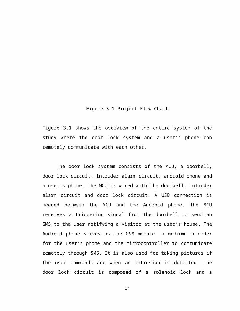
3.1 Project Flow
The implementation of the lock system proceeds as follows:
Figure 3.1 Project Flow Chart
9
Figure 3.1 shows the overview of the entire system of the study where the door lock
system and a user’s phone can remotely communicate with each other.
The door lock system consists of the MCU, a doorbell, door lock circuit, intruder
alarm circuit, android phone and a user’s phone. The MCU is wired with the doorbell,
intruder alarm circuit and door lock circuit. A USB connection is needed between the
MCU and the Android phone. The MCU receives a triggering signal from the doorbell to
send an SMS to the user notifying a visitor at the user’s house. The Android phone serves
as the GSM module, a medium in order for the user’s phone and the microcontroller to
communicate remotely through SMS. It is also used for taking pictures if the user
commands and when an intrusion is detected. The door lock circuit is composed of a
solenoid lock and a driver circuit for automatic locking and unlocking of the lock and an
opto- interrupter sensor for the intruder alarm circuit.
3.2 Software Tools
3.2.1 Eclipse and Android SDK
Eclipse is a multi-language Integrated development environment (IDE)
comprising a base workspace and an extensible plug-in system for customizing the
environment. It is written mostly in Java and it is the official integrated development
environment (IDE) supported by Android SDK using the Android Development Tools
(ADT) Plug-in. The Android software development kit (SDK) which is developed by
Google includes a comprehensive set of development tools. This includes a debugger,
libraries, a handset emulator based on QEMU, documentation, sample code, and tutorials.
The two go hand in hand in configuring and making applications for Android phones
with the help of Java Development Kit (JDK) for proper functionality. Through
downloading the adt-bundle-windows-x86_64-20130917 which is compatible for 64-bit
system, the necessary API’s needed by the system were downloaded through the SDK
10

Manager. The API used was based on the version of the Android Phone we were using,
which is API level 16 since the phone has an OS version of 4.1.2 where it belongs to.
3.2.2 Arduino IDE 1.0.4
Arduino IDE 1.0.4 will be the integrated development environment (IDE) that
will be used in this study. The Arduino IDE is intended for the Arduino Boards. It is a
cross-platform application written in Java which is capable of compiling and uploading
programs to the board with a single click. It will enable the proponents to develop and
compile the necessary codes written in C or C++ programming language. In order for the
Android Phone to communicate with the microcontroller, the ADK Reference Package
was downloaded and extracted to install the two necessary libraries which are the
AndroidAccessory and USB_HOST_Shield and put it in the
<arduino_folder_root>/library directory. It has two important methods for coding, first is
the setup method which only runs once at the beginning of the code execution, this is
where initializing routines are placed and second is the loop method, which runs in an
endless loop until the board is reset, this is where the program logic are implemented.
11
3.3 Software Implementation
3.3.1 System Flow
Figure 3.3.1 System FlowIn Figure 3.3.1, it shows the system flow of the proposed project. After starting
the system, it will check if one of the actions is present: Alarm was tripped, Door bell
was pressed or Command was received, then the system will respond according to the
action present at the moment. If, however, two or more actions are present, it will first
check and take action first when Alarm was tripped, second, when Doorbell is pressed
and third when a command was received. After the system has properly completed its
responses, it will loop back to checking the system again if one of the actions is present.
12

3.3.2 Intruder Alarm, Command Received & Doorbell Flow Chart
Figure 3.3.2 Intruder Alarm Flow Chart
Figure 3.3.3 Command Received Flow Chart
13

Figure 3.3.4 Doorbell Flow Chart
Figures 3.3.2, 3.3.3, & 3.3.4 above, show the corresponding process taken when a
certain action is detected or checked.
For the Intruder Alarm Flow Chart, the system will be initialized first, thus every
component and circuits are set to its default state. It will then check if the Door lock
alarm was activated. If it was triggered, the microcontroller sends a CAPTURE IMAGE
command to the Android Phone. The phone will take one picture as triggered by the
microcontroller. The microcontroller will then send INTRUDER command to the
Android phone, which will send the captured image to the users’ registered numbers
along with an intruder alert message.
For the Command Received Flow Chart, it will ask if there is a received
command from the user. When there is no received command, the system will still be on
its default state. If there is a received message, it will check what mode or command is it
in. For LOCK mode, the microcontroller will output a “0” or a low voltage to the door
lock circuit which will make the electromagnetic lock locked. For UNLOCK mode, the
microcontroller will output “1” or high voltage to the door lock circuit which will make
14

the electromagnetic lock unlocked. For the TAKE PICTURE mode, the microcontroller
will send a CAPTURE IMAGE command to the android phone. It will then send
VISITOR command, which will send the captured image to the user’s phone with a
visitor alert message.
In Figure 3.3.4, the system starts with the initialization of all the components that
composes the system. If the doorbell is activated, the microcontroller will process the
command from the doorbell to the Android phone and then sends an SMS to the user that
there is someone at the door. If the user receives the SMS then he/she will then decide to
take a picture of the person who is at the doorstep or not. If the user decides to take a
picture then the microcontroller will send a command to the Android phone to capture the
image and process the image captured from the Android phone and sends it to the user.
3.4 Hardware Integration
The door lock system consists of the microcontroller, the doorbell, the android
phone, the door lock circuit, the intruder alarm circuit and the power supply. Only this
part of the system has the hardware input and output function in order to be sent to the
user phone.
3.4.1 Arduino Mega ADK
The Arduino Mega ADK microcontroller board is based on the ATmega2560. It
has a Universal Serial Bus (USB) host interface to connect with Android based phones,
based on the MAX3421e IC. It has 54 digital input/output pins (of which 15 can be used
as PWM outputs), 16 analog inputs, 4 UARTs (hardware serial ports), a 16 MHz crystal
oscillator, a USB connection, a power jack, an ICSP header, and a reset button. It can be
powered through a USB cable, an AC-to-DC adapter or a battery [9].
The Arduino Mega ADK was used as the main microcontroller of the door lock
system since it is compatible and specifically used for smart phone with Android OS
version from 3.1 and later with the use of the USB library which is also back ported on
OS version 2.3.4 and 2.3.3. It communicates to USB devices through the USB Host Chip
15
included in the board with the use of the three libraries MAX3421e, Usb and Android
Accessory. The MAX3421e handles the USB Host Chip, the Usb handles the USB
communication and the Android Accessory handles the checking if the device connecting
is one of the available accessory-enabled phones. In order for the microcontroller and the
Android phone to communicate with each other it should be assured that the two passed
back and forth product and Vendor ID’s that supports accessory mode which you can see
when you connect the two devices, for the two to communicate the Vendor ID must be
from Google which is 0x18D1 and the Product ID must either be 0x2D00 or 0x2D01 to
established connection to communicate. This microcontroller acts as the USB Host which
controls all the commands of the system.
3.4.2 Android Phone
An Android phone was used as the system transceiver and GSM module
interfaced with the microcontroller. It has an open source Linux-based operating system
in which applications are developed through Java language using the Eclipse IDE and the
Android SDK which provides the API libraries and developer tools necessary to build,
test and debug apps for Android. It is the one responsible for the sending and receiving of
the SMS and MMS to the user’s phone if ever the commands are executed.
LG Optimus V (E612) with an OS version of 4.1.2 and an API level 16 was used
as the android phone in the system which is connected to the microcontroller through a
USB cable. The phone was used since it is compatible to the microcontroller because of
its Vendor and Product ID that corresponds to the supported ID’s which are 0x18D1 and
0x2D01 respectively. The phone gets its power from the microcontroller. This phone acts
as an Accessory to the microcontroller since it is not capable of functioning as a Host.
3.4.3 Lock Driver Circuit
The Lock driver circuit was used as the driving circuit for the solenoid lock. It is
composed of a 2N2222 NPN transistor, MTP3925 P-MOSFET and diodes. The diode
16

was used to protect the transistor from back emf generated by the relay coil at transient
points. The 2n2222 is a NPN bipolar junction transistor, it suits for small relays. When
the input is 1 the state of the solenoid lock is lock, and when 0 the state of the solenoid is
unlock. The input supply is taken from pin5 (analog input) of the MCU.
3.4.4 Intruder Alarm Circuit
Opto-interrupter was used as the sensor to detect when there is intrusion, whenever there is an object blocking the sensor, the voltage of collector-emitter is high and low when there is no object block. An inverter is used to light the led when there is intrusion and off when it is not trip. Pin6 is connected to the circuit as an input pin from the MCU and pin5 as the output pin to the MCU. The circuit schematic and layout can be found at the Appendix C.
3.4.4 Electromagnetic Lock
A lock-style solenoid lock 12VDC was used as the door lock of the system. It
consist an electromagnet and an armature plate. It uses the concept of electromagnetism,
when the lock is applied 12V it instantly opens and locks when power is cut. It has a
driver circuit to control its state. The study belongs to a fail secure type of electric
locking devices. Fail secure locking device remains locked when power is lost.
3.4.5 Power Supply
The power supply that was used is an external power source of 12VDC output of an AC-DC converter from the 220V AC supply. It was used to drive the solenoid lock and to power the arduino Mega ADK. The 5V supply is used in triggering the doorbell and for the intruder circuit will be taken from the output voltage of the Arduino Mega ADK. The output voltage (5V) of the arduino was used as the input voltage of the driver circuit.
17

3.5 Hardware Implementation
The overview of the system is presented below:
Figure 3.5 System Block Diagram
Figure 3.5 shows the overview of the entire system of the proposed study where
the door lock system and a user’s phone can remotely communicate with each other.
The door lock system consists of the MCU, a doorbell, door lock circuit, android
phone and a user’s phone. The MCU is wired with the doorbell and the door lock circuit.
A USB connection is needed between the MCU and the Android phone. The MCU
receives a triggering signal from the doorbell to send an SMS to the user notifying a
visitor at the user’s house. The Android phone serves as the GSM module, a medium in
order for the user’s phone and the microcontroller to communicate remotely. The
Android phone is also used for taking pictures if the user commands and when an
intrusion is detected. The door lock circuit which is composed of an electromagnetic lock
and a relay circuit for automatic locking and unlocking and for the intruder alarm.
18

3.6 Coding of the Arduino Mega ADK and the Android App
The Arduino Mega ADK was programmed for controlling the lock, the intruder
alarm circuit, the doorbell and the Android Phone. It was programmed using Arduino
1.0.4 IDE for the configuration of the commands. First thing to do is to make the
microcontroller and Android Phone recognized each other by connecting them together
through USB connection. For the Arduino coding, some descriptive strings are added that
contains the initialization of an AndroidAccessory object, the important parameters are
Manufacturer, Model and Version these parameters should coincide with the parameters
declared in eclipse for building the app. In the setup routine, an active state of the object
with the powerOn method should be set always since it is in this part that the Arduino
checks if there is an Accessory connected to it. When connection is established, the serial
monitor will print the lines below:
Figure 3.7 Serial Monitor output of the Arduino application
recognizing the Android Phone.
Once the lines below are achieved, the two devices now recognized each other.
For the two devices to communicate there is a self-defined protocol to be defined since
messages are sent and received via byte-streams in Android App this is done by reading
the input-and output stream of a special file. The message to be sent and received is
composed of 3 bytes which are the command byte which defines what kind of message to
be transmitted, the target byte which will define the actual target for that command and
the value byte which defines the actual value to be transmitted to or from the target.
These bytes should be declared in both the Arduino and Eclipse.
19
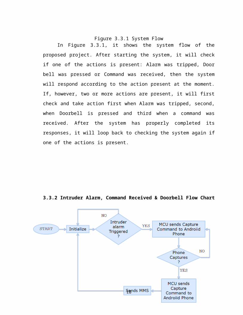
Figure 3.8 Microcontroller Unit Program Flow
For the Android part, there are steps to follow for the Android Phone to
communicate to the microcontroller. First is to specify the intent filter for the USB
Accessory. Second is to declare the corresponding resource file that specifies the USB
accessories, the declaration should be the same as that of the microcontroller. Third is to
obtain permission to communicate with the accessory connected. Fourth is to register
broadcast receiver in the onCreate() method. Fifth is to use the UsbManager to obtain a
file descriptor to set up the input and output streams to read and write data to descriptor
and last is to terminate communication to the accessory when it is done communicating
or if t is detached by closing the file descriptor by calling close().
20
Baud Rate Communication Configuration
Define the Different Variable Declarations and
the Pin Constants to be controlled
Read the Received Data into the Byte Array and Sends Data to Android
depending on the Command
Executes the commands received
and sent
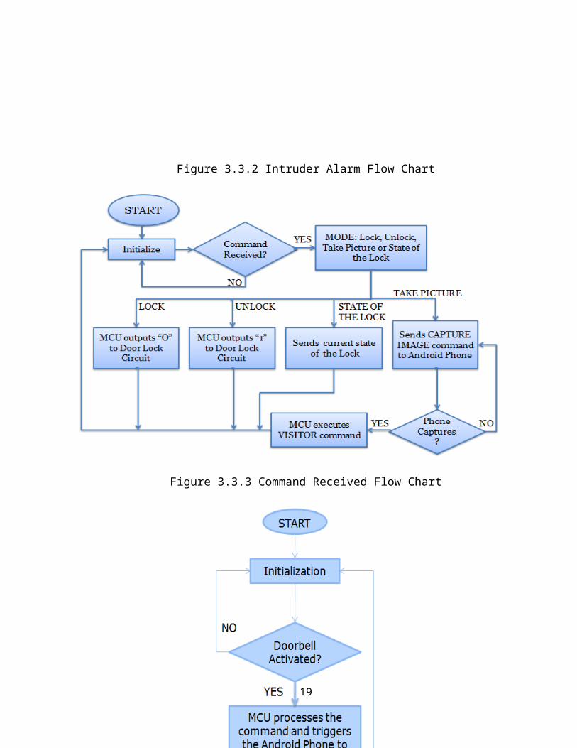
Figure 3.9 Android Activity Lifecycle
The development of the Android App is composed of three classes which are the
MainActivity.java, IncomingSms.java and the CameraPreview.java. The Main
Activity.java is the class where the code for communicating the Android Phone, the App
and microcontroller were established. The IncomingSms.java is the class responsible for
receiving the incoming and sending the outgoing SMS and the CameraPreview.java is the
21

class responsible for the previewing of the Camera to be displayed on the screen of the
Android phone.
3.7 Testing
Preliminary test on the individual components or parts will be conducted first on
the project. Individual testing on the door lock circuit, the microcontroller with the
Android phone when the user sends commands, if the system will respond after being
triggered by the doorbell and if the Android phone captures an image after receiving a
command from the controller. Preliminary tests will be done before integrating the
system.
After system integration, the prototype of the project will be tested. During the
prototype testing, the proponents will try and access the system by first sending
commands and triggering the doorbell and the alarm on the system at different places,
different places with different signal strength in order to test how fast the system will
respond. Data will be collected from the success and failure of attempts by sending
commands and receiving SMS and MMS.
22

Chapter 4
Results and Discussions
This study aimed to developed a remotely door lock system where users can
remotely access the door and monitor the state of the door. The system was tested
according to its performance, reliability and based on different factors. This chapter
presents the different findings and our analysis based on the outcome of different trials.
Table of the results are shown and observed trends are discussed.
23

Chapter 5
Conclusions and Recommendations
5.1 Conclusions
An SMS controlled Door Lock with image capture using Android Phone was
designed to monitor the front door of the house when homeowners are not around. The
researchers were able to build a prototype system which is composed of an Arduino
Mega ADK microcontroller, Solenoid Lock and its driver circuit, an intruder alarm
circuit with an Opto Interrupter as the sensor and the Android Application from an
Android Phone which acts as the transceiver of the system that receives the commands
from the homeowner.
The researchers were able to design and build the circuits used in the system and
the Android Application. The intruder alarm circuit operates when the Opto- interrupter
is triggered through the homeowner’s command of the system to activate the intruder
circuit that allows it to take picture instantly and stores it in the memory card of the
phone.
All in all, the researchers were able to monitor and control wirelessly the front
doorlock of the house through SMS. Out from the tests that were made, the delay, failure
and success of the sending and receiving of SMS vary according to the signal strength of
the Android Phone. The Door Lock Prototype was implemented and able to accomplish
the objectives stated in this project except for sending the captured image through MMS
because of the fact that Google did not include MMS API support for android 4.0 and
above.
5.2 Recommendations
After a thorough analysis of the data, the following recommendations have been made:
The system should have a back-up power supply to prevent outrage of power when sudden power failure occurs.
24

The Solenoid Lock should be replaced with an electromagnetic lock that can be accessed by a key so that the homeowner can use the key when there is outage of power.
The App made must be developed more so that it can be accessed through registered numbers only specified in the App and can reply to the registered numbers when commands are executed not just to the number who sent the commands.
25

Bibliography
[1] [ONLINE] http://www.numbeo.com/crime/city_result.jsp?country=Philippines&city=Manila
[2] [ONLINE] https://en.wikipedia.org/wiki/2G
[3] Scott Velivis, Rob Lee-Own, Max Sobell, Vincent Lin “Remote Door Lock Project,” Stevens Institute of Technology, May 2010.
[4] Mohd Helmi Alysyukran Bin Abd Malik “Automatic Door Lock System,” Universiti Teknologi Malaysia, April 2008.
[5] Sikarwar, Shailendra S.,”Security Intrusion Alert Method and Device to Communicate via SMS,” International Journal of Wireless Communication (Bioinfo), 2011.
[6] Johndon-Edd Magallanes, Sean MichaelRuiz, Cris Encallado, Kristian Niño Capoy “Design and Implementation of Home Security System Based on Laser Trip Alarm with Webcam and GPRS Module Interface,” University of San Carlos, March 2013.
[7] Chauhan, Singh, Agrawal, Kapoor, Sharma, “SMS based Remote Control System,” IJCSMS International Journal of Computer Science and Management Studies, vol. 11, Issue 02, Aug 2011.
[8] Raymart Aurora, Joseph Eulen Caballo, Dexter Paalisbo, Wuven Sabala “Wireless Sensor Network-Based Appliance Monitoring Using STM32 Microcontroller and XBee Module via Android App Mobile Access Panel (MAP),” University of San Carlos, March 2013.
[9] [ONLINE] http://arduino.cc/en/Main/ArduinoBoardADK
26

APPENDICES
27

Appendix A
Gantt Chart
28

Appendix B
Bill of Materials
Items Price (Php) Quantity Total Cost Arduino Mega ADK 3500 1 3500
Android Phone 1Solenoid Lock 1
Pre-synthesized PCB 100 1 100Power Splitter Adapter Cable 80 1 80
PrintingLoad ----- ----- 104
Skid Protector 59.75 1 59.75Screw 1.5 10 15
1N4001 1 4 42N2222 8 1 8
RESISTOR .50 10OPTO-INTERRUPTER 45 1 45
MTP2955 95 1 95Shipping & Delivery Miscellaneous 50
Total Amount:
29

Appendix C
Schematic Diagram and Layouts
Door Lock driver circuit and Push button
30

Intruder Alarm Circuit
31

32
Curriculum VitaeName Gil Maica Marie V.
Filomeno
Nickname gil, maica
Address Lapu-Lapu City, Cebu, Philippines
Contact Number
09339681059
Email Address [email protected]
Pick-up Lines My love for you is like a concave up function because it is always increasing.
Personal Background
Date of Birth December 18, 1992
Gender Female
Nationality Filipino
Educational Background
College Education
University of San Carlos – Talamban Campus, Batch 2014
Bachelor of Science in Electronics Engineer
Secondary Education
Saint Alphonsus Catholic School, Batch 2009
Primary Education
Lapu-Lapu City Central Elementary School, Batch 2005

Curriculum Vitae
33
Curriculum VitaeName Michelle P. Ledon
Nickname mich, michelle
Address Mahayahay, Lapu-Lapu City, Philippines
Contact Number
09327812230
Email Address [email protected]
Pick-up Lines Let's convert our potential energy to kinetic energy.
Personal Background
Date of Birth July 29, 1992
Gender Female
Nationality Filipino
Educational Background
College Education
University of San Carlos – Talamban Campus, Batch 2014
Bachelor of Science in Electronics Engineer
Secondary Education
Asian Learning Center, Batch 2009 Primary Education
Asian learning Center, Batch 2005

Name Prima Socorro L. Lenares
Nickname prima, primz, prim2x
Address Poblacion, Dalaguete, Cebu, Philippines
Contact Number
09336923705
Email Address [email protected]
Pick-up Lines You're hotter than a Bunsen burner set to full power!
Personal Background
Date of Birth April 14, 1993
Gender Female
Nationality Filipino
Educational Background
College Education
University of San Carlos – Talamban Campus, Batch 2014
Bachelor of Science in Electronics Engineer
Secondary Education
St. Mary’s Academy of Dalaguete, Batch 2009
Primary Education
Dalaguete Central Elementary School, Batch 2005
34