04 gb - efes otomasyon - endüstriyel otomasyon ac drive acp 3000 user... · 04_gb acp 3000 —...
TRANSCRIPT

Operating manual0.37–15 kW


21.12.98 Operating manual
04_GB ACP 3000 — 0.37–15.0
Berges electronic • D–51709 Marienheide-Rodt • Tel. 02264/17-0 • Fax 02264/17126
Parameter Code Summary
PARA-METER
DESCRIPTION FACTORYSETTING
RANGE PAGE CUSTOMERSETTING
02-RVLVL Software Revision 35
03-IRAT Inverter Rated Current A 35
07-FLT3 Last Fault 36
08-FLT2 Second Fault 36
09-FLT1 First Fault 36
12-FOUT Motor Output Frequency 0.00–400.0 Hz 36
13-VOUT Motor Output Voltage 0–100%of line voltage
36
14-IOUT Motor Output Current 0.00–60.00 A 36
15-LOAD Inverter Load 0–200%of 03-IRAT
36
17-TEMP Inverter Temperature 0.00–110.0 °C 36
1A-FSTAT Stator-Frequency (1) Hz 55 Read-only
21-MODE Input Mode 3 (2) 0–11 36/55
24-FSEL Speed Setpoint Selector 0 (2) 0–19 38/55
31-FMIN Minimum Frequency 0.00 Hz 0.00–400.0 Hz 38
32-FMAX Maximum Frequency 50.00 Hz 20.00–400.0 Hz 38
33-F2 Preset Frequency 2 5.00 Hz 0.00–400.0 Hz 38
34-F3 Preset Frequency 3 20.00 Hz 0.00–400.0 Hz 38
35-F4 Preset Frequency 4 40.00 Hz 0.00–400.0 Hz 38
36-F5 Preset Frequency 5 50.00 Hz 0.00–400.0 Hz 38
37-F6 Preset Frequency 6 0.00 Hz 0.00–400.0 Hz 38
38-F7 Preset Frequency 7 0.00 Hz 0.00–400.0 Hz 38
39-FTL Minimum Frequency in Torque Limit 10.00 Hz 0.00–400.0 Hz 39
41-RSEL Ramp Selector 0 (2) 0–7 39/56
42-ACC1 Acceleration Time 1 3.00 s 0.10–600.0 s 39
43-DEC1 Deceleration Time 1 3.00 s 0.10–600.0 s 39
44-ACC2 Acceleration Time 2 1.00 s 0.10–600.0 s 40
45-DEC2 Deceleration Time 2 1.00 s 0.10–600.0 s 40
46-DECTL Deceleration Time in Torque Limit 1.00 s 0.10–30.00 s 40
47-DCBRK DC Brake Time 0.20 s 0.00–5.00 s 40
48-DCVLT DC Brake Voltage 2/3 of 52-BOOST 0–15% 40
51-VSEL V/Hz Characteristic Selector 0 0–5 40
52-BOOST Voltage Boost 8.00% 0.00–25.00% 41
53-FKNEE V/Hz Knee Frequency 50.00 Hz 26.00–400.0 Hz 42
54-SKBND Skip Frequency Hysteresis Band 1.00 Hz 0.20–20.00 Hz 42
55-SK1 Skip Frequency 1 0.00 Hz 0.00–400.0 Hz 42
56-SK2 Skip Frequency 2 0.00 Hz 0.00–400.0 Hz 42
57-SK3 Skip Frequency 3 0.00 Hz 0.00–400.0 Hz 42
59-MVOLT Rated Motor Voltage 230/400 V 185–240 V;370–480 V
42
5B-MSAT Motor Saturation Level 47% 15–80% 42
61-LTLF Load Torque Limit Forward 150% 10–150% 42

Berges electronic • D–51709 Marienheide-Rodt • Tel. 02264/17-0 • Fax 02264/17126
Operating manual 21.12.98
ACP 3000 — 0.37–15.0 04_GB
NOTES:
Level 1 Parameters shown shaded.
(1) Additional parameters that are only available when using the PI controller and whenthe 81-PRGNO parameter is set to a value between 80 and 95 (see page 56). Seechapter 6, from page 51 on, for further information about the PI controller.
(2) Extended parameters when using the PI controller. For further information about thePI controller, see chapter 6, as from page 51.
62-LTLR Load Torque Limit Reverse 150% 10–150% 42
63-RTLF Regenerative Torque Limit Forward 80% 10–110% 42
64-RTLR Regenerative Torque Limit Reverse 80% 10–110% 42
65-SLIP Slip Compensation 0.00% (2) 0.00–12.00% 43/56
66-STAB Current Stability Adjustment 3 0–4 43
67-TOL Timed Overload Trip Point 0% 0–100% 43
68-NRST Trip Restart Number 0 0–8 44
69-DRST Restart Delay Time 0.00 s 0.00–60.00 s 44
6A-TOLC Timed Overload Characteristic 0 0–7 45
70-MCAL Analog Meter Output Calibration MET1 Set for10 VDC 0–255 45
71-METER Analog Meter Output Selector MET1 1 (2) 0–5 45/56
72-ST1 Open Collector Output 1 7 0–10 46
75-STR Auxiliary Relay Output 1 0–10 46
77-MOL Motor Overload Input 2 0–3 47
78-MCAL2 Analog Meter Output Calibration MET2 0–20 mA or 4–20 mA;set for 20 mA
0–255 47
79-MET2 Analog Meter Output Selector MET2 3 (2) 0–15 47/56
81-PRGNO Special Program/PI Control Characteristics 0 0–9999 48/56
82-START Start Options 1 0–11 48
83-PWM PWM Carrier Frequency Selector 1 0–5 49
84-DISP Display Option Setting 0 0–3000 49
87-ACODE Security Access Code 0 0–999 50
97-RVLVL2 Software Revision Level 2 0.00–12.75 50 Read-only
A1-FCORR Frequency Correction (1) 0.00–400.0 Hz 55
A6-ERROR2 Final Error (1) – 55 Read-only
A7-ERROR1 Initial Error (1) – 55 Read-only
A8-SIPART Integral Sum (1) – 55 Read-only
B3-KP Proportional Gain (1) 0–255 55
B4-KI Integral Gain (1) 0–255 55
B5-KIN VIN1 Scaling (1) 0–255 55
PARA-METER
DESCRIPTION FACTORYSETTING
RANGE PAGE CUSTOMERSETTING

21.12.98 Operating manual
04_GB ACP 3000 — 0.37–15.0 1
Berges electronic • D–51709 Marienheide-Rodt • Tel. 02264/17-0 • Fax 02264/17126
Table of Contents
Page
1 General Information . . . . . . . . . . . . . . . . . . . . . . . . . . . . . . . . . . . . . . . . . . . . . . . . . . . . . . 3
1.1 Explanation of Symbols and Notes . . . . . . . . . . . . . . . . . . . . . . . . . . . . . . . . . . . . . 3
1.2 Safety and Operating Instructions for Drive Converters. . . . . . . . . . . . . . . . . . . . . . 3
1.3 Preface. . . . . . . . . . . . . . . . . . . . . . . . . . . . . . . . . . . . . . . . . . . . . . . . . . . . . . . . . . . 5
2 Technical Data . . . . . . . . . . . . . . . . . . . . . . . . . . . . . . . . . . . . . . . . . . . . . . . . . . . . . . . . . . 6
2.1 Model Identification Number . . . . . . . . . . . . . . . . . . . . . . . . . . . . . . . . . . . . . . . . . . 6
2.2 Power Specifications . . . . . . . . . . . . . . . . . . . . . . . . . . . . . . . . . . . . . . . . . . . . . . . . 6
2.3 General Drive Specifications . . . . . . . . . . . . . . . . . . . . . . . . . . . . . . . . . . . . . . . . . . 7
2.4 Dimensional Data (Size I) . . . . . . . . . . . . . . . . . . . . . . . . . . . . . . . . . . . . . . . . . . . . 8
2.4.1 Dimensional Data (Size II) . . . . . . . . . . . . . . . . . . . . . . . . . . . . . . . . . . . . . . . . . . . . 9
2.4.2 Dimensional Data (Size III) . . . . . . . . . . . . . . . . . . . . . . . . . . . . . . . . . . . . . . . . . . . 9
2.4.3 Dimensional Data (Size IV) . . . . . . . . . . . . . . . . . . . . . . . . . . . . . . . . . . . . . . . . . . 10
3 Installation . . . . . . . . . . . . . . . . . . . . . . . . . . . . . . . . . . . . . . . . . . . . . . . . . . . . . . . . . . . . . 11
3.1 Inspection. . . . . . . . . . . . . . . . . . . . . . . . . . . . . . . . . . . . . . . . . . . . . . . . . . . . . . . . 11
3.2 General Rules for Installation. . . . . . . . . . . . . . . . . . . . . . . . . . . . . . . . . . . . . . . . . 11
3.3 EMC (Electromagnetic Compatibility) . . . . . . . . . . . . . . . . . . . . . . . . . . . . . . . . . . 12
3.3.1 Suggestion on how to solve the Problem of Radio Frequency InterferenceSuppression of Frequency Converters to VDE 0875/EN 55011 . . . . . . . . . . . . . . 12
3.3.2 Mains Filters/Output Chokes . . . . . . . . . . . . . . . . . . . . . . . . . . . . . . . . . . . . . . . . . 13
3.3.3 Filter Specifications . . . . . . . . . . . . . . . . . . . . . . . . . . . . . . . . . . . . . . . . . . . . . . . . 14
3.3.4 Interference Suppression Measures . . . . . . . . . . . . . . . . . . . . . . . . . . . . . . . . . . . 15
3.4 EMC Ordinance (EMC Directive, 89/336 EEC) . . . . . . . . . . . . . . . . . . . . . . . . . . . 17
3.5 Wiring Practices . . . . . . . . . . . . . . . . . . . . . . . . . . . . . . . . . . . . . . . . . . . . . . . . . . . 18
3.5.1 Applicable Codes . . . . . . . . . . . . . . . . . . . . . . . . . . . . . . . . . . . . . . . . . . . . . . . . . . 18
3.5.2 Power Wiring . . . . . . . . . . . . . . . . . . . . . . . . . . . . . . . . . . . . . . . . . . . . . . . . . . . . . 18
3.5.3 Control Wiring/Interface . . . . . . . . . . . . . . . . . . . . . . . . . . . . . . . . . . . . . . . . . . . . . 18
3.6 Mains Power Connection . . . . . . . . . . . . . . . . . . . . . . . . . . . . . . . . . . . . . . . . . . . . 19
3.6.1 Mains Conditions . . . . . . . . . . . . . . . . . . . . . . . . . . . . . . . . . . . . . . . . . . . . . . . . . . 20
3.6.2 Line Protection . . . . . . . . . . . . . . . . . . . . . . . . . . . . . . . . . . . . . . . . . . . . . . . . . . . . 21
3.6.3 Using Mains Filters. . . . . . . . . . . . . . . . . . . . . . . . . . . . . . . . . . . . . . . . . . . . . . . . . 22
3.6.4 Line Starting. . . . . . . . . . . . . . . . . . . . . . . . . . . . . . . . . . . . . . . . . . . . . . . . . . . . . . 23
3.7 Motor Connection. . . . . . . . . . . . . . . . . . . . . . . . . . . . . . . . . . . . . . . . . . . . . . . . . . 23
3.8 Reducing Current Surges and Voltage Transients. . . . . . . . . . . . . . . . . . . . . . . . . 23
3.9 Function and Use of Terminals . . . . . . . . . . . . . . . . . . . . . . . . . . . . . . . . . . . . . . . 24
3.10 Terminal Access Cover Removal. . . . . . . . . . . . . . . . . . . . . . . . . . . . . . . . . . . . . . 25
3.11 Terminal Assignment (Mains supply 1 × 230 VAC, 0.37–4.0 kW) . . . . . . . . . . . . . 26
3.12 Terminal Assignment (Mains supply 3 × 400 VAC, 0.37–4.0 kW) . . . . . . . . . . . . . 26
3.13 Terminal Assignment (Mains supply 3 × 400 VAC, 5.5–15.0 kW) . . . . . . . . . . . . . 27
3.14 Remote Keypad/Program Memory Unit Connector (J22) . . . . . . . . . . . . . . . . . . . 27
3.15 Control Terminal Description . . . . . . . . . . . . . . . . . . . . . . . . . . . . . . . . . . . . . . . . . 27
3.16 J20 Configuration. . . . . . . . . . . . . . . . . . . . . . . . . . . . . . . . . . . . . . . . . . . . . . . . . . 29

Berges electronic • D–51709 Marienheide-Rodt • Tel. 02264/17-0 • Fax 02264/17126
Operating manual 21.12.98
ACP 3000 — 0.37–15.0 04_GB2
Page
4 Getting Started . . . . . . . . . . . . . . . . . . . . . . . . . . . . . . . . . . . . . . . . . . . . . . . . . . . . . . . . . 30
4.1 General Information . . . . . . . . . . . . . . . . . . . . . . . . . . . . . . . . . . . . . . . . . . . . . . . . 30
4.2 Digital Keypad . . . . . . . . . . . . . . . . . . . . . . . . . . . . . . . . . . . . . . . . . . . . . . . . . . . . 30
4.3 Keypad Operation . . . . . . . . . . . . . . . . . . . . . . . . . . . . . . . . . . . . . . . . . . . . . . . . . 30
4.4 Operation Mode (RUN and STOP Modes). . . . . . . . . . . . . . . . . . . . . . . . . . . . . . . 31
4.5 Program Mode . . . . . . . . . . . . . . . . . . . . . . . . . . . . . . . . . . . . . . . . . . . . . . . . . . . . 31
4.6 Status Indicator . . . . . . . . . . . . . . . . . . . . . . . . . . . . . . . . . . . . . . . . . . . . . . . . . . . 32
4.7 Description of Displays. . . . . . . . . . . . . . . . . . . . . . . . . . . . . . . . . . . . . . . . . . . . . . 32
4.8 Programming Tips . . . . . . . . . . . . . . . . . . . . . . . . . . . . . . . . . . . . . . . . . . . . . . . . . 33
4.9 Quick Start . . . . . . . . . . . . . . . . . . . . . . . . . . . . . . . . . . . . . . . . . . . . . . . . . . . . . . . 34
5 Parameter Configuration and Description . . . . . . . . . . . . . . . . . . . . . . . . . . . . . . . . . . . 35
5.1 Programming . . . . . . . . . . . . . . . . . . . . . . . . . . . . . . . . . . . . . . . . . . . . . . . . . . . . . 35
5.2 Parameter Descriptions . . . . . . . . . . . . . . . . . . . . . . . . . . . . . . . . . . . . . . . . . . . . . 35
6 PI Controller . . . . . . . . . . . . . . . . . . . . . . . . . . . . . . . . . . . . . . . . . . . . . . . . . . . . . . . . . . . 51
6.1 Introduction . . . . . . . . . . . . . . . . . . . . . . . . . . . . . . . . . . . . . . . . . . . . . . . . . . . . . . 51
6.2 Overview of PI Control . . . . . . . . . . . . . . . . . . . . . . . . . . . . . . . . . . . . . . . . . . . . . . 51
6.3 Reference and Feedback Inputs . . . . . . . . . . . . . . . . . . . . . . . . . . . . . . . . . . . . . . 53
6.4 Calculating PI Controller Values. . . . . . . . . . . . . . . . . . . . . . . . . . . . . . . . . . . . . . . 54
6.5 Parameters for PI Control. . . . . . . . . . . . . . . . . . . . . . . . . . . . . . . . . . . . . . . . . . . . 54
7 Connection Diagrams . . . . . . . . . . . . . . . . . . . . . . . . . . . . . . . . . . . . . . . . . . . . . . . . . . . . 58
7.1 AC Line and Motor Connections (Mains supply 1 × 230 VAC and 3 × 400 VAC) . 58
7.2 2-Wire Run/Stop Connections . . . . . . . . . . . . . . . . . . . . . . . . . . . . . . . . . . . . . . . . 59
7.3 3-Wire Run/Stop Connections . . . . . . . . . . . . . . . . . . . . . . . . . . . . . . . . . . . . . . . . 59
7.4 Auxiliary Relay Output and Digital Output ST1 . . . . . . . . . . . . . . . . . . . . . . . . . . . 59
7.5 MOL Terminal Connections . . . . . . . . . . . . . . . . . . . . . . . . . . . . . . . . . . . . . . . . . . 60
7.6 Analog Speed Input Connections (VIN1/VIN2) . . . . . . . . . . . . . . . . . . . . . . . . . . . 60
7.7 Optional Connections. . . . . . . . . . . . . . . . . . . . . . . . . . . . . . . . . . . . . . . . . . . . . . . 61
8 Troubleshooting . . . . . . . . . . . . . . . . . . . . . . . . . . . . . . . . . . . . . . . . . . . . . . . . . . . . . . . . 62
8.1 Special Indications . . . . . . . . . . . . . . . . . . . . . . . . . . . . . . . . . . . . . . . . . . . . . . . . . 62
8.2 Fault Trip Indications . . . . . . . . . . . . . . . . . . . . . . . . . . . . . . . . . . . . . . . . . . . . . . . 62
8.3 Resetting a Fault . . . . . . . . . . . . . . . . . . . . . . . . . . . . . . . . . . . . . . . . . . . . . . . . . . 63
8.4 Fault Codes . . . . . . . . . . . . . . . . . . . . . . . . . . . . . . . . . . . . . . . . . . . . . . . . . . . . . . 63
9 Appendix . . . . . . . . . . . . . . . . . . . . . . . . . . . . . . . . . . . . . . . . . . . . . . . . . . . . . . . . . . . . . . 65
9.1 Parameter Code Summary. . . . . . . . . . . . . . . . . . . . . . . . . . . . . . . . . . . . . . . . . . . 65
9.2 Parameters Added or Amended when PI Control is Utilized . . . . . . . . . . . . . . . . . 67
9.3 Options. . . . . . . . . . . . . . . . . . . . . . . . . . . . . . . . . . . . . . . . . . . . . . . . . . . . . . . . . . 67

21.12.98 Operating manual
04_GB ACP 3000 — 0.37–15.0 3
Berges electronic • D–51709 Marienheide-Rodt • Tel. 02264/17-0 • Fax 02264/17126
1 General Information
1.1 Explanation of Symbols and Notes
Work Safety Symbol
You will find this symbol next to all work safety notes in this operating manual if there is arisk of injury or death for persons involved. Pay attention to these notes and observe par-ticular caution in such cases. Also pass on all work safety instructions to other users.
Voltage Warning
This symbol is shown wherever particular caution is necessary owing to occurring or ap-plied voltages (e.g. DC voltages up to 650 V) and where special precautionary measureshave to be taken. The inverter must always be isolated from the mains when working on it.
Caution Note
This note is shown in all parts of this operating manual to which particular attention must bepaid to ensure that the guidelines, specifications, notes and the correct sequence of workwill be obeyed and to prevent damage or destruction of the inverter and/or systems.
1.2 Safety and Operating Instructions for Drive Converters
1. General
In operation, drive converters, depending on their degree of protection, may have live,unisolated, and possibly also moving or rotating parts, as well as hot surfaces.
In case of inadmissible removal of the required covers, of improper use, wrong installationor maloperation, there is the danger of serious personal injury and damage to property.
For further information, see documentation.
All operations serving transport, installation and commissioning as well as maintenance areto be carried out by skilled technical personnel (Observe IEC 364 or CENELEC HD 384or DIN VDE 0100 and IEC 664 or DIN/VDE 0110 and national accident prevention rules!).
For the purposes of these basic safety instructions, “skilled technical personnel” means per-sons who are familiar with the installation, mounting, commissioning and operation of theproduct and have the qualifications needed for the performance of their functions.
We draw attention to the fact that no liability can be assumed for damage and malfunctionsresulting from failure to observe the operating manual.
Technical amendments of illustrations and data given in this operating manual are reservedin the interest of improving the unit and its functions.
2. Intended Use
The application of the drive converter described in this operating manual exclusively servesthe purpose of continuously variable speed control of three-phase motors.
Drive converters are components designed for inclusion in electrical installations or machin-ery.
The drive converters are designed for installation in a switchgear cabinet and for permanentconnection.
The operator of the system is solely liable for damage resulting from improper use of thedrive converter.
ATTENTION!

Berges electronic • D–51709 Marienheide-Rodt • Tel. 02264/17-0 • Fax 02264/17126
Operating manual 21.12.98
ACP 3000 — 0.37–15.0 04_GB4
Only items expressly approved by BERGES (e.g. mains filter, choke, external braking chop-pers and braking resistors etc.) may be used as accessories.
The installer of the system is liable for any damage resulting from the use of accessoriesthat have not been approved expressly by BERGES. Please consult us in case of doubt.
In case of installation in machinery, commissioning of the drive converters (i.e. the startingof normal operation) is prohibited until the machinery has been proved to conform to theprovisions of the directive 89/392/EEC (Machinery Safety Directive – MSD). Account is tobe taken of EN 60204.
Commissioning (i.e. the starting of normal operation) is admissible only where conformitywith the EMC directive (89/336/EEC) has been established.
The drive converters meet the requirements of the low-voltage directive 73/23/EEC. Theyare subject to the harmonized standards of the series prEN 50178/DIN VDE 0160 in con-junction with EN 60439-1/DIN VDE 0660, part 500, and EN 60146/DIN VDE 0558.
The technical data as well as information concerning the supply conditions shall be takenfrom the rating plate and from the documentation and shall be strictly observed.
3. Transport, Storage
The instructions for transport, storage and proper use shall be complied with.
Damage established after delivery must be notified to the transport company immediately.Where necessary, the supplier must also be notified before the damaged drive converter isput into operation.
The climatic conditions shall be in conformity with prEN 50178.
4. Installation
The installation and cooling of the appliances shall be in accordance with the specificationsin the pertinent documentation.
The drive converters shall be protected against excessive strains. In particular, no compo-nents must be bent or isolating distances altered in the course of transportation or handling.No contact shall be made with electronic components and contacts.
Drive converters contain electrostatic sensitive components which are liable to damagethrough improper use. Electric components must not be mechanically damaged or de-stroyed (potential health risks).
5. Electrical Connection
When working on live drive converters, the applicable national accident prevention rules(e.g. VBG 4) must be complied with.
The electrical installation shall be carried out in accordance with the relevant requirements(e.g. cross-sectional areas of conductors, fusing, PE connection). For further information,see documentation.
Instructions for the installation in accordance with EMC requirements, like screening, earth-ing, location of filters and wiring, are contained in the drive converter documentation. Theymust always be complied with, also for drive converters bearing a CE marking. Observanceof the limit values required by EMC law is the responsibility of the manufacturer of the in-stallation or machine.
6. Operation
The components of the power section and certain elements of the control section are con-nected to the voltage mains when the drive converter is connected to the mains voltage.Touching these components involves mortal danger!
Always isolate the drive converter from the mains supply before performing any work on theelectrical or mechanical part of the system.

21.12.98 Operating manual
04_GB ACP 3000 — 0.37–15.0 5
Berges electronic • D–51709 Marienheide-Rodt • Tel. 02264/17-0 • Fax 02264/17126
Isolate the drive converter from the mains before removing the terminal cover or the hous-ing (e.g. by removing or deactivating on-site fuses or by deactivating a master switch iso-lating all poles etc.).
After disconnection of the drive converters from the voltage supply, live appliance parts andpower terminals must not be touched immediately because of possibly energized capaci-tors. In this respect, the corresponding signs and markings on the drive converter must berespected. After switching off the mains voltage, wait for at least 5 minutes before begin-ning work on or in the drive converter. Dangerous voltages are still present as long as the“STATUS” lamp is still lit. In the event of malfunctions, the discharge time of 5 minutes maybe exceeded substantially.
The drive converter contains protective facilities that deactivate it in the event of malfunc-tions, whereby the motor is de-energized and comes to a standstill (so-called “coasting” ofthe motor is possible depending on the rotating mass of the type of drive involved). Stand-still of the motor can, however, also be produced by mechanical blockage. Voltage fluctua-tions, and particularly mains power failures, may also lead to deactivation. In certaincircumstances, the drive may start up automatically once the cause of the fault has beenremedied. As a result of this, certain systems may be damaged or destroyed and there maybe a risk for operators working on the system. Installations which include drive convertersshall be equipped with additional control and protective devices in accordance with the rel-evant applicable safety requirements, e.g. Act respecting technical equipment, accidentprevention rules etc. Changes to the drive converters by means of the operating softwareare admissible.
The motor may be stopped during operation by disabling it or by deactivating the setpoint,whereby the drive converter and motor may remain live. If inadvertent start-up of the mo-tor must be excluded to protect operating personnel, electronic interlocking by dis-abling the motor or by deactivating the setpoint is inadequate. This is why the driveconverter must be isolated from the mains voltage.
During operation, all covers and doors shall be kept closed.
Measuring instruments must be connected and disconnected only in de-energized condi-tion.
Unauthorized conversions or modifications on or in the drive converter and its componentsand accessories will render all warranty claims void.
Please contact BERGES if conversions or modifications are necessary, particularly if elec-trical components are involved.
7. Maintenance and Servicing
The manufacturer's documentation shall be followed.
KEEP SAFETY INSTRUCTIONS IN A SAFE PLACE!
1.3 Preface
The present manual contains the specifications, installation instructions, description of op-eration and troubleshooting procedures for ACP 3000 inverters. The information in thismanual must be known before installation of the inverter in order to guarantee fault-free in-stallation and thus maximum performance.
Before you read on, please check whether technical changes are at-tached in the annex to this operating manual!

Berges electronic • D–51709 Marienheide-Rodt • Tel. 02264/17-0 • Fax 02264/17126
Operating manual 21.12.98
ACP 3000 — 0.37–15.0 04_GB6
2 Technical Data
2.1 Model Identification Number
All ACP 3000 models bear a systematic identification number designating the rated inputvoltage, the rated power and the housing type. This model number appears both on theshipping carton label and the technical data label on the drive.
2.2 Power Specifications
Models with Supply Voltage 1 × 230 VAC
Models with Supply Voltage 3 × 400 VAC
* = Maximum inverter capacity. Value = 1.1 × 03-IRAT (see page 35).
Example type marking
Model ACP 3300-3 3300-5 3300-7 3301-1 3301-5 3302-2
Kilowatt (kW) 0.37 kW 0.55 kW 0.75 kW 1.1 kW 1.5 kW 2.2 kW
Output Voltage Three Phase 3.5–230 VAC
Rated current 1.94 A 2.6 A 3.4 A 4.8 A 6.4 A 9.0 A
Maximum Output Current * 2.1 A 2.9 A 3.7 A 5.3 A 7.0 A 9.9 A
Input Volts (±10%) 208–230 V~
Maximum Input Current 3.1 A 4.7 A 6.4 A 9.4 A 12.7 A 18.6 A
Table 2.1
Model ACP 3600-7 3601-5 3602-2 3603-0 3604-0 3605-5 3607-5 3611-0 3615-0
Kilowatt (kW) 0.75 kW 1.5 kW 2.2 kW 3.0 kW 4.0 kW 5.5 kW 7.5 kW 11.0 kW 15.0 kW
Output Voltage Three Phase 7.0–460 VAC
Rated current 1.95 A 3.7 A 5.2 A 6.8 A 9.2 A 13.0 A 18.0 A 24.0 A 30.0 A
Maximum Output Current * 2.1 A 4.1 A 5.7 A 7.5 A 10.1 A 14.3 A 19.8 A 26.4 A 33.0 A
Input Volts (±10%) 400–460 V~
Maximum Input Current 2.11 A 4.2 A 6.2 A 8.4 A 11.2 A 16.0 A 22.2 A 31.0 A 37.9 A
Table 2.2
21.12.98 Operating manual
04_GB ACP 3000 — 0.37–15.0 7
Berges electronic • D–51709 Marienheide-Rodt • Tel. 02264/17-0 • Fax 02264/17126
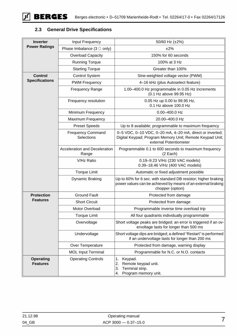
2.3 General Drive Specifications
InverterPower Ratings
Input Frequency 50/60 Hz (±2%)
Phase Imbalance (3 ∅ only) ±2%
Overload Capacity 150% for 60 seconds
Running Torque 100% at 3 Hz
Starting Torque Greater than 100%
ControlSpecifications
Control System Sine-weighted voltage vector (PWM)
PWM Frequency 4–16 kHz (plus Autoselect feature)
Frequency Range 1.00–400.0 Hz programmable in 0.05 Hz increments(0.1 Hz above 99.95 Hz)
Frequency resolution 0.05 Hz up 0.00 to 99.95 Hz,0.1 Hz above 100.0 Hz
Minimum Frequency 0.00–400.0 Hz
Maximum Frequency 20.00–400.0 Hz
Preset Speeds Up to 8 available; programmable to maximum frequency
Frequency CommandSelections
0–5 VDC, 0–10 VDC, 0–20 mA, 4–20 mA, direct or inverted;Digital Keypad; Program Memory Unit; Remote Keypad Unit;
external Potentiometer
Acceleration and Deceleration Range
Programmable 0.1 to 600 seconds to maximum frequency(2 Each)
V/Hz Ratio 0.19–9.23 V/Hz (230 VAC models)0.39–18.46 V/Hz (400 VAC models)
Torque Limit Automatic or fixed adjustment possible
Dynamic Braking Up to 60% for 6 sec. with standard DB resistor; higher braking power values can be achieved by means of an external braking
chopper (option)
ProtectionFeatures
Ground Fault Protected from damage
Short Circuit Protected from damage
Motor Overload Programmable inverse time overload trip
Torque Limit All four quadrants individually programmable
Overvoltage Short voltage peaks are bridged; an error is triggered if an ov-ervoltage lasts for longer than 500 ms
Undervoltage Short voltage dips are bridged; a defined “Restart” is performed if an undervoltage lasts for longer than 200 ms
Over Temperature Protected from damage, warning display
MOL Input Terminal Programmable for N.C. or N.O. contacts
OperatingFeatures
Operating Controls 1. Keypad.2. Remote keypad unit.3. Terminal strip.4. Program memory unit.
Berges electronic • D–51709 Marienheide-Rodt • Tel. 02264/17-0 • Fax 02264/17126
Operating manual 21.12.98
ACP 3000 — 0.37–15.0 04_GB8
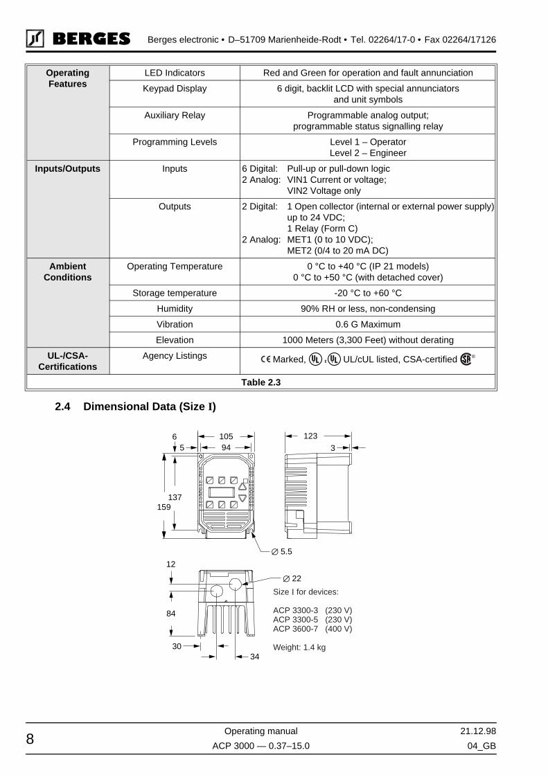
2.4 Dimensional Data (Size I)
OperatingFeatures
LED Indicators Red and Green for operation and fault annunciation
Keypad Display 6 digit, backlit LCD with special annunciatorsand unit symbols
Auxiliary Relay Programmable analog output;programmable status signalling relay
Programming Levels Level 1 – OperatorLevel 2 – Engineer
Inputs/Outputs Inputs 6 Digital: Pull-up or pull-down logic2 Analog: VIN1 Current or voltage;
VIN2 Voltage only
Outputs 2 Digital: 1 Open collector (internal or external power supply)up to 24 VDC;1 Relay (Form C)
2 Analog: MET1 (0 to 10 VDC);MET2 (0/4 to 20 mA DC)
AmbientConditions
Operating Temperature 0 °C to +40 °C (IP 21 models)0 °C to +50 °C (with detached cover)
Storage temperature -20 °C to +60 °C
Humidity 90% RH or less, non-condensing
Vibration 0.6 G Maximum
Elevation 1000 Meters (3,300 Feet) without derating
UL-/CSA-Certifications
Agency Listings Marked, UL/cUL listed, CSA-certified
Table 2.3
UL®ULC ®
®
∅ 22
∅ 5.5
3430
84
12
159137
56 105
94123
3
Size for devices:
ACP 3300-3 (230 V)ACP 3300-5 (230 V)ACP 3600-7 (400 V)
Weight: 1.4 kg
I

21.12.98 Operating manual
04_GB ACP 3000 — 0.37–15.0 9
Berges electronic • D–51709 Marienheide-Rodt • Tel. 02264/17-0 • Fax 02264/17126
2.4.1 Dimensional Data (Size II)
2.4.2 Dimensional Data (Size III)
65
140129
1253
137159
∅ 5.5
∅ 22
5438
84
12
Size for devices:
ACP 3300-7 (230 V)ACP 3301-1 (230 V)ACP 3601-5 (400 V)
Weight: 1.9 kg
II
140129
1535
220
188
5
119
4147
∅ 29
∅ 22
∅ 5.5
Size for devices:
ACP 3301-5 (230 V)ACP 3302-2 (230 V)ACP 3602-2 (400 V)ACP 3603-0 (400 V)ACP 3604-0 (400 V)
Weight: 3.45 kg
III

Berges electronic • D–51709 Marienheide-Rodt • Tel. 02264/17-0 • Fax 02264/17126
Operating manual 21.12.98
ACP 3000 — 0.37–15.0 04_GB10
2.4.3 Dimensional Data (Size IV)
221200
1806
280
327
133
4647
53
∅ 35
∅ 29
∅ 5.5
Size for devices:
ACP 3605-5 (400 V)ACP 3607-5 (400 V)ACP 3611-0 (400 V)ACP 3615-0 (400 V)
Weight: 8.6 kg
IV

21.12.98 Operating manual
04_GB ACP 3000 — 0.37–15.0 11
Berges electronic • D–51709 Marienheide-Rodt • Tel. 02264/17-0 • Fax 02264/17126
3 Installation
3.1 Inspection
A. Upon receipt, unpack and carefully inspect for any damage sustained in transit (depres-sion in the enclosure, damage to parts, missing parts).
B. Remove the cover (see page 25) and inspect the inverter for any apparent damage orforeign objects. Ensure that all mounting hardware and terminal connection hardware isproperly seated, securely fastened, and undamaged.
C. Read the technical data label and ensure that the correct rated output and input voltagefor the application has been purchased.
D. If the inverter is to be stored for a long period of time, repack and store in a clean, dryplace, free from direct sunlight or corrosive fumes, and in a location where the ambienttemperature will not be less then -20 °C nor more than +60 °C.
3.2 General Rules for Installation
Improper installation of the inverter will greatly effect its life. Be sure to observe the followingpoints when selecting a mounting location. VIOLATING THE CONDITIONS LISTED BE-LOW MAY VOID THE WARRANTY!
A. Mount the unit vertically and do not restrict the airflow to the heat sink fins on the backof the controller. The fan and fins allow cooling of internal components. Any air restric-tion could greatly reduce the life of the inverter, as well as resulting in nuisance overtem-perature trips.
B. The ACP inverter generates heat, and therefore there must be a sufficient amount offree space around the unit (see Figure 3.1). If the unit is accommodated in a housingtogether with a different unit, the prescribed minimum distances must be observed sothat adequate ventilation can be ensured.
C. If the inverter has to be installed in a different position, external cooling is required forfull capacity utilization. In certain circumstances, the internal air circulation does not suf-fice when installing the unit in a control cabinet with a small volume. Therefore, wheninstalling the unit, you must ensure that a heat buildup is prevented.
D. Do not mount the ACP near heat generating equipment, or in direct sunlight. BERGESinverters are generally designed so that they can be operated at ambient temperaturesof 0 °C to +50 °C (IP 00) or 0 °C to 40 °C (IP 21) and at a relative humidity of up to 90%.
The occurrence of condensate must be avoided!
Figure 3.1

Berges electronic • D–51709 Marienheide-Rodt • Tel. 02264/17-0 • Fax 02264/17126
Operating manual 21.12.98
ACP 3000 — 0.37–15.0 04_GB12
E. Do not install the inverter in a place subjected to high temperature, high humidity, or ex-cessive vibration (see Table 2.3, “Ambient Conditions”)
F. The units should never be installed in the proximity of corrosive or flammable gases,conductive dust or large magnetic and electric fields.
G. Pay close attention during installation to ensuring that no objects (such as drilling swarf,wire or anything else) fall into the unit. Otherwise, a device fault cannot be excluded,even after longer periods of operation.
H. Do not use wire end ferrules for the control terminals. The terminals are designedso that the wires can be inserted in the terminals after twisting the individualwires.
I. Table 3.1 shows the watts generated by the inverter when at full current. The heat gen-erated is dependent on the carrier frequency used. For carrier frequencies other thanthose shown in Table 3.1, consult BERGES or use the worst-case scenario (16 kHz car-rier).
3.3 EMC (Electromagnetic Compatibility)
3.3.1 Suggestion on how to solve the Problem of Radio Frequency Interference Suppression of Frequency Converters to VDE 0875/EN 55011
It is necessary to connect a mains filter type “BE/(xxx) xxxx” before every frequency con-verter. The size (xxx) depends on the rated current of the unit. A motor choke can be dis-pensed with.
The motor choke type BV... may be necessary as from a cable length in excess of 20 m andwhen operating several motors in parallel on one frequency converter output. This chokeattenuates the capacitive earth leakage currents and considerably reduces wire-borne in-terference voltages.
HEAT GENERATED BY INVERTER (IN WATTS)
Inverter Model Number @ 4 kHz Carrier @ 16 kHz Carrier
3300-3 19 27
3300-5 37 42
3300-7 66 75
3301-1 66 75
3301-5 70 79
3302-2 129 154
3600-7 40 62
3601-5 67 99
3602-2 118 186
3603-0 184 281
3604-0 184 281
3605-5 280 640
3607-5 360 790
3611-0 470 1120
3615-0 610 1400
Table 3.1
ATTENTION!
HINT!

21.12.98 Operating manual
04_GB ACP 3000 — 0.37–15.0 13
Berges electronic • D–51709 Marienheide-Rodt • Tel. 02264/17-0 • Fax 02264/17126
The converter and accessories must be wired in accordance with the following schematic.To render the remaining interference voltage at the PE conductor potential ineffective for“external measurement systems”, the following proposed circuit will achieve successful re-sults if applied consistently.
3.3.2 Mains Filters/Output Chokes
ACP 3000
DEVICE TYPE MAINS FILTER ARTICLE NO. INPUT PHASES VOLTAGE (V) CURRENT (A) WEIGHT (kg) FOOTPRINT
ACP 3300-3 BE I 1005 32501739 1~ 250 5 0.60 (1)
(1) FOOTPRINT means that these filters have been prepared for the installation of an ACP converter on the filter (securing).
ACP 3300-5 BE I 1005 32501739 1~ 250 5 0.60 (1)
ACP 3300-7 BE II 1010 32501740 1~ 250 10 0.70 (1)
ACP 3301-1 BE II 1010 32501740 1~ 250 10 0.70 (1)
ACP 3301-5 BE III 1020 32501741 1~ 250 20 1.05 (1)
ACP 3302-2 BE III 1020 32501741 1~ 250 20 1.05 (1)
ACP 3600-7 BE I 3003 32501742 3~ 380/480 3 0.75 (1)
ACP 3601-5 BE II 3005 32501743 3~ 380/480 5 0.80 (1)
ACP 3602-2 BE III 3012 32501744 3~ 380/480 12 1.15 (1)
ACP 3603-0 BE III 3012 32501744 3~ 380/480 12 1.15 (1)
ACP 3604-0 BE III 3012 32501744 3~ 380/480 12 1.15 (1)
ACP 3605-5 BE IV 3038 32501745 3~ 380/480 38 1.90 (1)
ACP 3607-5 BE IV 3038 32501745 3~ 380/480 38 1.90 (1)
ACP 3611-0 BE IV 3038 32501745 3~ 380/480 38 1.90 (1)
ACP 3615-0 BE IV 3038 32501745 3~ 380/480 38 1.90 (1)

Berges electronic • D–51709 Marienheide-Rodt • Tel. 02264/17-0 • Fax 02264/17126
Operating manual 21.12.98
ACP 3000 — 0.37–15.0 04_GB14
3.3.3 Filter Specifications
All BERGES line filters are provided in IP20 enclosures. They can operate over a temper-ature range of -10 to +50 °C (-23 to +122 °F). The filters can be mounted parallel or per-pendicular to the control panel. The filter is supplied with the correct mounting hardware formounting the inverter on top of the filter enclosure (Footprint).
The mains filters and chokes must be installed and connected in conformity with the rec-ommendations given in chapters 3.3.1 (page 12), 3.3.4 (page 15) and 3.6.3 (page 22).
ACP 3000
DEVICE TYPE CHOKE ARTICLE NO. INPUT PHASES VOLTAGE (V) CURRENT (A) WEIGHT (kg) FOOTPRINT
ACP 3300-3 BV 20394/307 32501345 – 440 7 0.25 –
ACP 3300-5 BV 20394/307 32501345 – 440 7 0.25 –
ACP 3300-7 BV 20394/307 32501345 – 440 7 0.25 –
ACP 3301-1 BV 20394/307 32501345 – 440 7 0.25 –
ACP 3301-5 BV 20394/307 32501345 – 440 7 0.25 –
ACP 3302-2 BV 20394/313 32501346 – 440 13 0.70 –
ACP 3600-7 BV 20394/307 32501345 – 440 7 0.25 –
ACP 3601-5 BV 20394/307 32501345 – 440 7 0.25 –
ACP 3602-2 BV 20394/307 32501345 – 440 7 0.25 –
ACP 3603-0 BV 20394/307 32501345 – 440 7 0.25 –
ACP 3604-0 BV 20394/313 32501346 – 440 13 0.70 –
ACP 3605-5 BV 20394/313 32501346 – 440 13 0.70 –
ACP 3607-5 BV 20394/325 32501347 – 440 25 1.10 –
ACP 3611-0 BV 20394/325 32501347 – 440 25 1.10 –
ACP 3615-0 BV 20394/330 32501348 – 440 30 1.15 –
ATTENTION!

21.12.98 Operating manual
04_GB ACP 3000 — 0.37–15.0 15
Berges electronic • D–51709 Marienheide-Rodt • Tel. 02264/17-0 • Fax 02264/17126
NOTE: Dimensions in mm.(1)
3.3.4 Interference Suppression Measures
Electrical/electronic devices are capable of influencing or disturbing each other throughconnecting cables or other metallic connections. “Electromagnetic compatibility” consists ofthe factors “interference resistance” and “interference emission”. Correct installation ofthe inverter in conjunction with any possible local interference suppression meas-ures has a crucial effect on minimizing or suppressing mutual interference.
TYPE OUTER DIMENSIONS SECURING SECURING ON THE INVERTER
CONNECTIONS FOOT-PRINT
A B C D E F G H I J (PE) K
BE I 1005 200 108 40 183 80 M5 137 94 M5 M4 2,5 mm2 (1)
BE II 1010 200 145 40 183 110 M5 137 129 M5 M4 2,5 mm2 (1)
BE III 1020 250 145 45 235 110 M5 188 129 M5 M4 2,5 mm2 (1)
BE I 3003 200 108 40 183 80 M5 137 94 M5 M4 2,5 mm2 (1)
BE II 3005 200 145 40 183 110 M5 137 129 M5 M4 2,5 mm2 (1)
BE III 3012 250 145 45 235 110 M5 188 129 M5 M5 2,5 mm2 (1)
BE IV 3038 360 222 50 342 160 M6 280 200 M6 M5 16 mm2 (1)
BE V 3012 360 222 50 342 160 M6 280 200 M6 M5 16 mm2 (1)
BE VI 3040 496 232 50 478 180 M6 419 200 M6 M5 16 mm2 (1)
Table 3.2
(1) FOOTPRINT means that these filters have been prepared for the installation of an ACP converter on the filter (securing).

Berges electronic • D–51709 Marienheide-Rodt • Tel. 02264/17-0 • Fax 02264/17126
Operating manual 21.12.98
ACP 3000 — 0.37–15.0 04_GB16
The scope of noise suppression measures depends on the limit value class, the local situ-ation and the application.
The following notes refer to a mains power supply that is not “contaminated” by high fre-quency interference. Other measures may be necessary to reduce or suppress interferenceif the mains voltage is “contaminated”. No generally valid recommendations can be givenin such cases. Please consult BERGES if all recommended interference suppressionmeasures should not produce the desired result.
Basically, it is not the cross section of the conductor that is important for radio-frequencyinterference suppression but the surface area. Since the high-frequency interference doesnot flow through the entire cross section but mainly on the outer surface of the conductor(skin effect), braided copper tapes of corresponding cross section should be used.
All conductive housing parts must be interconnected using corresponding lines. Minimumcross sections are prescribed for a fault case at 50 Hz (referred to the range of the safetyregulations) which must be observed under all circumstances.
The inverter and all other components used for interference suppression (especially alsothe shield of the motor cable) should be contacted over as large an area as possible whenconnected to metal (control panels, switchgear cabinets and similar) (skin effect). Removethe paint at the respective areas to ensure good contacting over a large area!
A central earthing point should be used for interference suppression (e.g. equipotentialbonding strip or centrally at an interference suppression filter). The earthing lines are routedto the respective terminals radially from this point. Conductor loops of the earthing linesare impermissible and can lead to unnecessary interference.
The shield cross section must not be reduced when the shield is connected to continuinglines. This would give rise to RF resistance at a cross section reduction, and the resultingRF energy would consequently not be discharged but radiated. Shields – particularlyshields of control lines – must not be contacted via pin contacts of plug connectors. In thesecases, the metallic hand guard of the plug connector should be used for large-area connec-tion of the shield.
Use a shielded motor cable (earthed over a large area at both sides). The shield should berouted uninterrupted from the PE terminal of the inverter to the PE terminal of the motor.If a shielded motor line cannot be used, the unshielded motor line should be laid in a metalduct. The metal duct must be uninterrupted and adequately earthed. The following pointsare prescribed if radio interference suppression is to be realized in accordance with EN55011, EN 55014 and EN 50081-1:
• Preceding the unit by a mains filter or a mains filter and a output choke (mains filter andoutput choke not included in the scope of delivery).
• Laying the motor cable in a shielded configuration.• Laying the control cable in a shielded configuration.• Observe general RFI suppression measures (refer to the chapters 3.3.1 and 3.3.4).
Lay motor, mains power and signal cables as far away from each other as possible and sep-arately.
If a mains filter is used, the smallest possible spatial distance from the frequency invertermust be selected so that both units can be connected by short connection leads.
If an output choke is used (option), it must be fitted in the direct vicinity of the inverter andconnected to the inverter via screened cables earthed at both ends.
Shielded signal cables should be laid at a minimum distance of 10 cm from power cablesrunning parallel. A separate earthed metal cable duct is advisable for such signal cables. Ifsignal cables intercept with a power cable, they should do so at an angle of 90°.

21.12.98 Operating manual
04_GB ACP 3000 — 0.37–15.0 17
Berges electronic • D–51709 Marienheide-Rodt • Tel. 02264/17-0 • Fax 02264/17126
Control lines longer than 1 m must be laid with a shield and earthed at one side on the fre-quency inverter. The screen is earthed via terminal “CM” in the case of pull-up logic andpull-down logic (see “Connection Diagrams”, chapters 7.1 to 7.7). If cables have lengths inexcess of 10 m, use a 0–20 mA control signal because of the possibility of parasitics. Theinverter can be switched over to this mode of operation. See parameter 24-FSEL (chapter5.2, page 38).
Other loads connected to the mains may produce voltage spikes that may interfere withfunctioning of the inverter or may even damage it. Chokes or mains filters can be used onthe mains side to protect the inverter against voltage spikes (resulting from switching largeloads to the mains). Such chokes and filters are available as accessories.
If inverters are operated in switchgear devices or in their close proximity (e.g. in one com-mon control cabinet) in connection with the same power mains, we recommend the follow-ing precautionary measures to suppress interference in the switchgear:
• Wire the coils of contactors, switchgear devices and relay combinations with “RC ele-ments” or with free-wheel diodes.
• Use shielded cables for external control and measuring cables.• Lay disturbing cables (e.g. power and contactor control circuits) separately and at a dis-
tance from the control cables.
3.4 EMC Ordinance (EMC Directive, 89/336 EEC)
The frequency inverters were tested in the form of a practical test set-up in a switchgearcabinet (in accordance with our interference suppression measures in these operating in-structions: “EMC (electromagnetic compatibility)”. The limit values of the standards belowwere fulfilled under these conditions:
EMA (Electromagnetic Emission)
EN 50081-1 Basic specification “Emitted interference” (Limit value class A)orEN 50081-2 Basic specification “Emitted interference” (Limit value class B)EN 55011 Emitted interference
EMB (Electromagnetic Interference)
EN 50082-2 Basic specification “Interference immunity”EN 50140 Electromagnetic fieldsEN 60801 Static discharge (ESD)IEC 801-4 Burst on mains lead/data line
At least the following conditions must be fulfilled for compliance withthe limit values of the aforementioned standards:
• Installation of a mains filter or a mains filter and a motor choke (mains filter and motorchoke are not included in the scope of delivery).
• Laying the motor cable in a shielded configuration.• Laying the control cable in a shielded configuration.• Observe general RFI suppression measures (refer to the chapters 3.3.1 and 3.3.4).
As the aforementioned interference resistance tests are based on standardised mains con-ditions, in extreme cases it may happen that the function of the inverter will be lost (mini-mum operating quality). This malfunction can generally be remedied by a RESET of theinverter. Refer to the chapter entitled “Resetting a Fault” and “Fault Codes” on page 63.
Detailed information and technical data relating to adapted mains filters and chokes can befound in the chapters 3.3.2, “Mains Filters/Output Chokes” and 3.3.3, “Filter Specifications”.
HINT!

Berges electronic • D–51709 Marienheide-Rodt • Tel. 02264/17-0 • Fax 02264/17126
Operating manual 21.12.98
ACP 3000 — 0.37–15.0 04_GB18
3.5 Wiring Practices
3.5.1 Applicable Codes
Pay conscientious attention to ensuring that the installation wiring is installed at least in con-formity with the NEC standards. Where local codes exceed these requirements, they mustbe followed.
All models are listed by the Underwriters Laboratories, Inc. (UL) and are certified by the Ca-nadian Underwriters Laboratories (cUL) and therefore conform to the requirements of NECand CEC. Installations that are to meet the requirements of UL and cUL must be realisedin conformity with the UL and cUL specifications. Refer to the corresponding electrical dataon the rating plates of the ACP 3000 unit and the motor.
3.5.2 Power Wiring
Power wiring are those wires which are connected during installation to the power circuitterminals, L1, N, L2, L3, M1, M2, and M3. Power wiring must be selected as follows:
1. Use only VDE, UL or cUL recognized wire.
2. Wire voltage rating must be a minimum of 300 V for 230 VAC systems, and 600 V for400 VAC systems.
3. The core cross section and the associated fuse are given in the tables in chapter 3.6.2,page 22. The wires must consist of copper and be designed for insulation temperaturesof 60 °C or 75 °C.
4. Grounding must be in accordance with VDE, NEC and CEC.
NOTES:
Never connect input AC power to the motor output terminals M1, M2 and M3 or dam-age to the drive will result.
The output voltage of variable-frequency controllers contains high-frequency componentsthat might cause disturbances in other installations. Therefore, avoid laying control cablesand mains input cables in the same cable duct or conduit together with the output cablesfrom the converter to the motor (see also chapter 3.3.4, “Interference Suppression Meas-ures”).
3.5.3 Control Wiring/Interface
All interfaces or control inputs and outputs possess only basic insulation by themains and must be incorporated in a further protective measure.
Use a dummy plug as additional protection if interface J22 is not allocated.
This is wiring connected to the control terminal strip (20 terminals). It must be selected asfollows:
1. Shielded wire is recommended to prevent electrical noise interference from causing im-proper operation or nuisance tripping. Only connect the screen on one end to the “CM”terminal on the converter’s control terminal strip (see also chapter 3.3.4, “InterferenceSuppression Measures”).
2. Use only VDE, UL or cUL recognized wire.
3. Wire voltage rating must be a minimum of 300 V for 230 VAC systems, and 600 V for400 VAC systems. This is Class 1 wire.
4. Never run the control wiring in the same conduit or raceway with power wiring.
ATTENTION!
ATTENTION!
21.12.98 Operating manual
04_GB ACP 3000 — 0.37–15.0 19
Berges electronic • D–51709 Marienheide-Rodt • Tel. 02264/17-0 • Fax 02264/17126
5. Do not use wire end ferrules for the control terminals. The terminals are designedso that the wires can be inserted in the terminals after twisting the individualwires.
3.6 Mains Power Connection
The frequency inverters are designed for installation in a switchgear cabinet and forpermanent connection.
To guarantee lasting operating safety and reliability, the inverter must be connected expert-ly in accordance with the valid electrical standards. Attention must be paid to good insula-tion from earth potential on the power terminals.
An AC system with a nominal voltage of 230 V (50/60 Hz) must be connected to mains ter-minals L1, N and PE or a three-phase system with a nominal voltage of 400 V (50/60 Hz)to terminals L1, L2, L3 and PE (pay attention to rating plate). The neutral point must beearthed (TN-C system).
Ensure a voltage balanced to earth or phase to phase when feeding in the mains powerthrough an isolating transformer (star point must be earthed).
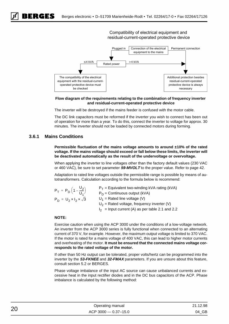
The single exception below permits connection of a frequency inverter via a residual-cur-rent-operated circuit-breaker as the sole protective measure:
• Installation of a residual-current-operated circuit-breaker of the newest design for fre-quency inverters up to 4 kVA (input voltage 1 × 230 V) with MOBILE connection.This residual current-operated circuit breaker must be suitable for alternating and pul-sating DC leakage current. Residual-current-operated circuit-breakers of this type bearthe symbol .
Reliable tripping of the residual-current-operated circuit-breaker is not ensured inthe case of frequency inverters up to 4 kVA (input voltage 3 × 400 V) with MOBILEconnection; an additional protective measure must be used for this reason. Also seethe diagram below.
In the case of frequency inverters with PERMANENT connection (input voltage 1 ×230 V and 3 × 400 V), another protective measure must always be used in addition tothe residual-current-operated protective device. Also see the diagram below.
The protective function of the residual-current-operated circuit-breaker is no longer ensureddue to leakage currents from interference suppression capacitors in the inverter and DCcomponents in the fault current. All devices connected to this residual-current-operated cir-cuit-breaker (and persons touching them) are no longer protected in the event of a fault.
Frequency inverters must not be connected via a residual-current-operated circuit-breaker as the sole protective measure!
Berges electronic • D–51709 Marienheide-Rodt • Tel. 02264/17-0 • Fax 02264/17126
Operating manual 21.12.98
ACP 3000 — 0.37–15.0 04_GB20
The inverter will be destroyed if the mains feeder is confused with the motor cable.
The DC link capacitors must be reformed if the inverter you wish to connect has been outof operation for more than a year. To do this, connect the inverter to voltage for approx. 30minutes. The inverter should not be loaded by connected motors during forming.
3.6.1 Mains Conditions
Permissible fluctuation of the mains voltage amounts to around ±10% of the ratedvoltage. If the mains voltage should exceed or fall below these limits, the inverter willbe deactivated automatically as the result of the undervoltage or overvoltage.
When applying the inverter to line voltages other than the factory default values (230 VACor 460 VAC), be sure to set parameter 59-MVOLT to the proper value. Refer to page 42.
Adaptation to rated line voltages outside the permissible range is possible by means of au-totransformers. Calculation according to the formula below is recommend:
NOTE:
Exercise caution when using the ACP 3000 under the conditions of a low-voltage network.An inverter from the ACP 3000 series is fully functional when connected to an alternatingcurrent of 370 V, for example. However, the maximum output voltage is limited to 370 VAC.If the motor is rated for a mains voltage of 400 VAC, this can lead to higher motor currentsand overheating of the motor. It must be ensured that the connected mains voltage cor-responds to the rated voltage of the motor.
If other than 50 Hz output can be tolerated, proper volts/hertz can be programmed into theinverter by the 53-FKNEE and 32-FMAX parameters. If you are unsure about this feature,consult section 5.2 or BERGES.
Phase voltage imbalance of the input AC source can cause unbalanced currents and ex-cessive heat in the input rectifier diodes and in the DC bus capacitors of the ACP. Phaseimbalance is calculated by the following method:
Flow diagram of the requirements relating to the combination of frequency inverter and residual-current-operated protective device
PT = Equivalent two-winding kVA rating (kVA)PD = Continuous output (kVA)U1 = Rated line voltage (V)U2 = Rated voltage, frequency inverter (V)I2 = Input current (A) as per table 2.1 and 2.2
PT PD 1U2
U1-------–
=
PD U2 I2× 3×=

21.12.98 Operating manual
04_GB ACP 3000 — 0.37–15.0 21
Berges electronic • D–51709 Marienheide-Rodt • Tel. 02264/17-0 • Fax 02264/17126
Assume:The voltage from L1 to L2 = LaThe voltage from L2 to L3 = LbThe voltage from L3 to L1 = LcThe average line voltage = Lavg
Determine the absolute value of the difference between each of the line voltages (La, Lband Lc) and Lavg. (Subtract the two values and disregard the sign of the result.) Considerthe results of this calculation to be Laa, Lba, and Lca.
Example: Measured phase voltages of 395, 400, and 405 would result in a calculatedphase imbalance of 1.25%.
If the resulting phase imbalance exceeds 2%, consult your local power company or plantmaintenance personnel and ask them to investigate this problem and recommend methodsof correcting this condition.
Phase imbalance can also cause damage to motors running direct on line. A 2% imbalancerequires a 5% derating factor on the motor, 3% imbalance requires a 10% derating. 4% re-quires an 18% derating.
NEVER USE POWER-FACTOR IMPROVEMENT CAPACITORS ON THE ACP MOTORTERMINALS, M1, M2, AND M3, OR DAMAGE TO THE INVERTER'S SEMICONDUC-TORS WILL RESULT!
3.6.2 Line Protection
It is necessary to provide either a circuit breaker or a fused disconnect switch on the inputAC line in accordance with all applicable electrical codes. The following rules should beused to select the correct size of the input line fuses or circuit breaker.
A. Sizing
The ACP inverter is able to withstand a 150% overload for 60 seconds. Minimum voltagerating for the protection device should be 250 VAC for models 3300-3 to 3302-2, and 600VAC for models 3600-7 to 3615-0.
B. Fuse Type
To guarantee a maximum protection of the inverter fuses should be used for current Limi-tation. These fuses should have a breaking capacity of 200,000 Aeff. The following tablesshows the recommended values in amps for all ACP-inverters.
For 230/400 V mains supplies we recommend time-lag type NEOZED-fuses.
LavgLa Lb Lc+ +
3------------------------------- 395 400 405+ +
3------------------------------------------ 400= = =
Phase ImbalanceLaa Lba Lca+ +
2 Lavg( )---------------------------------------- 100%× 5 0 5+ +
2 400×---------------------- 100%× 1.25%= = =
ATTENTION!
ATTENTION!
Berges electronic • D–51709 Marienheide-Rodt • Tel. 02264/17-0 • Fax 02264/17126
Operating manual 21.12.98
ACP 3000 — 0.37–15.0 04_GB22
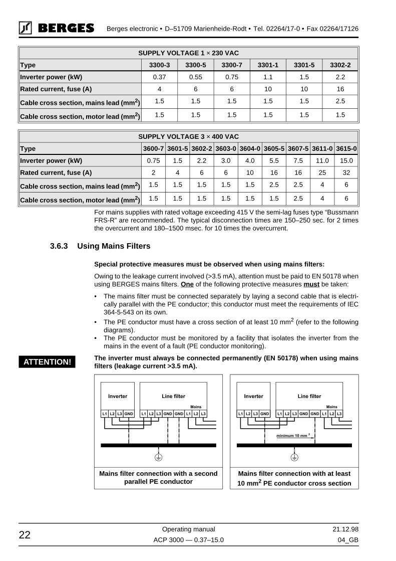
For mains supplies with rated voltage exceeding 415 V the semi-lag fuses type “BussmannFRS-R” are recommended. The typical disconnection times are 150–250 sec. for 2 timesthe overcurrent and 180–1500 msec. for 10 times the overcurrent.
3.6.3 Using Mains Filters
Special protective measures must be observed when using mains filters:
Owing to the leakage current involved (>3.5 mA), attention must be paid to EN 50178 whenusing BERGES mains filters. One of the following protective measures must be taken:
• The mains filter must be connected separately by laying a second cable that is electri-cally parallel with the PE conductor; this conductor must meet the requirements of IEC364-5-543 on its own.
• The PE conductor must have a cross section of at least 10 mm2 (refer to the followingdiagrams).
• The PE conductor must be monitored by a facility that isolates the inverter from themains in the event of a fault (PE conductor monitoring).
The inverter must always be connected permanently (EN 50178) when using mainsfilters (leakage current >3.5 mA).
SUPPLY VOLTAGE 1 × 230 VAC
Type 3300-3 3300-5 3300-7 3301-1 3301-5 3302-2
Inverter power (kW) 0.37 0.55 0.75 1.1 1.5 2.2
Rated current, fuse (A) 4 6 6 10 10 16
Cable cross section, mains lead (mm2) 1.5 1.5 1.5 1.5 1.5 2.5
Cable cross section, motor lead (mm2) 1.5 1.5 1.5 1.5 1.5 1.5
SUPPLY VOLTAGE 3 × 400 VAC
Type 3600-7 3601-5 3602-2 3603-0 3604-0 3605-5 3607-5 3611-0 3615-0
Inverter power (kW) 0.75 1.5 2.2 3.0 4.0 5.5 7.5 11.0 15.0
Rated current, fuse (A) 2 4 6 6 10 16 16 25 32
Cable cross section, mains lead (mm2) 1.5 1.5 1.5 1.5 1.5 2.5 2.5 4 6
Cable cross section, motor lead (mm2) 1.5 1.5 1.5 1.5 1.5 1.5 2.5 4 6
Mains filter connection with a secondparallel PE conductor
Mains filter connection with at least10 mm2 PE conductor cross section
ATTENTION!

21.12.98 Operating manual
04_GB ACP 3000 — 0.37–15.0 23
Berges electronic • D–51709 Marienheide-Rodt • Tel. 02264/17-0 • Fax 02264/17126
3.6.4 Line Starting
ACP 3000 is designed to provide controlled starting and stopping of AC motors by use ofthe keypad or external contacts connected to the control terminal strip. The drive may alsobe started by using a maintained contact (2-wire operation). To prevent accidental startingof the motor, the inverter has linestart-lockout as a standard feature. This provision can bedefeated by programming 82-START (see page 48).
The inverter may be started once every two (2) minutes in this mode.
3.7 Motor Connection
Connect the motor cable to the “M1, M2, M3” and “PE” terminals.
The inverter will be deactivated if shorted to the motor terminals.
The output of the drive will always be three phase. Do not connect single-phase mo-tors to the inverter output terminals M1, M2 or M3.
Never use power factor correction capacitors on the motor terminals M1, M2 and M3,or damage to the semi-conductors will result.
We recommend PTC evaluation using commercially available devices to achieve effectiveprotection of the motor.
If interrupting contacts (e.g. contactors or motor protection switches etc.) have to be in-stalled between the motor and inverter, the circuit must be configured so as to ensure thatthe “Enable” signal (terminals V+ and FWD/REV by pull-up logic, terminals CM and FWD/REV by pull-down logic) is deactivated before separation of the inverter/motor connection.A relay switching time of approx. 30 ms suffices.
In the case of special motors, the corresponding Volt/Hz values can be programmed on theinverter by means of the parameters 53-FKNEE and 32-FMAX. In cases of doubt, pleasecontact BERGES or refer to chapters 5.2 and 9.1.
3.8 Reducing Current Surges and Voltage Transients
Voltage spikes caused by coils (inductors operated on the same mains as the inverter) canlead to malfunctions of the inverter. In cases of this kind, the affected windings of contactorsand relays operated on the 230 VAC mains must be damped by fuses in the form of an RCseries circuit:
• Main Circuit Contactors and Solenoids: C = 0.2 MFD, 500 VDC; R = 500 W, 5 Watts.• Auxiliary Control Circuit Relays: C = 0.1 MFD, 500 VDC; R = 200 W, 2 Watts.
Connection Diagram for AC and DC Relay Coils and Solenoids:
Figure 3.2
ATTENTION!

Berges electronic • D–51709 Marienheide-Rodt • Tel. 02264/17-0 • Fax 02264/17126
Operating manual 21.12.98
ACP 3000 — 0.37–15.0 04_GB24
Free-wheeling diodes must be used on contactors, relays and solenoid coils operated withdirect current. The diodes in question should be fast types with short recovery time. Thediode must be connected in blocking direction in parallel with the winding (see Figure 3.2).The rated current and voltage of the diode can be calculated using the formulae below:
3.9 Function and Use of Terminals
Refer to section 7.1 to 7.7 – Connection Diagrams for power and control wiring examples.
A. Power Circuit Terminals
Power terminals are located on the power module of the ACP 3000 inverter. They are la-belled L1, L2, and L3 for incoming three phase AC line power (L1 and N for incoming single-phase AC line power), and M1, M2, and M3 for the motor connections.
Two ground connections (GND) are provided on the end plate of 0.37 to 4.0 kW IP 21 mod-els (see Figures 3.4 and 3.5), and along the power terminal strip of 5.5 to 15.0 kW IP 21models (Figure 3.6). Ground connections can be made to the heat sink on chassis models.The ground screws must be connected to earth ground in accordance with the NEC.
5.5 to 15.0 kW inverters also have two terminals, B+ and B-, that provide access to the DCbus rails for the addition of external dynamic braking kits, or extra bus capacitors for customapplications.
B. Control Terminals
The control terminals are located on the bottom edge of the inverter's control board. SeeFigures 3.4 to 3.6, page 26/27 and chapter 3.15. These terminals are available for use withexternal devices.
The 20-pole control terminal strip of the units, 0.37–4.0 kW, is plugged in and can be re-moved in the upward direction to connect the control cables. To do this, place a flat screw-driver on the metal tabs of the cover securing element and carefully lever off the terminalstrip in the upward direction.
NOTE:
Control input signals must not exceed 24 VDC ±20% potential to ground.
Logic Input Levels:
The input logic is compatible with either 12 or 24 VDC logic. J20 selects active High or Lowcontrol inputs.
LOGIC TYPE PULL-UP PULL-DOWN
Active 10–24 VDC 0–3 VDC
Inactive 0–3 VDC 10–24 VDC
Diode Current Rating (A) Coil Capacity (VA)Rated Voltage of Coil (V)------------------------------------------------------------------≥
Diode Voltage Rating (V) Rated Voltage of Coil (V) 2×≥
21.12.98 Operating manual
04_GB ACP 3000 — 0.37–15.0 25
Berges electronic • D–51709 Marienheide-Rodt • Tel. 02264/17-0 • Fax 02264/17126
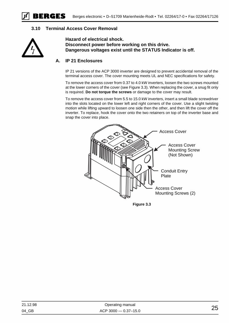
3.10 Terminal Access Cover Removal
Hazard of electrical shock.Disconnect power before working on this drive.Dangerous voltages exist until the STATUS Indicator is off.
A. IP 21 Enclosures
IP 21 versions of the ACP 3000 inverter are designed to prevent accidental removal of theterminal access cover. The cover mounting meets UL and NEC specifications for safety.
To remove the access cover from 0.37 to 4.0 kW inverters, loosen the two screws mountedat the lower corners of the cover (see Figure 3.3). When replacing the cover, a snug fit onlyis required. Do not torque the screws or damage to the cover may result.
To remove the access cover from 5.5 to 15.0 kW inverters, insert a small blade screwdriverinto the slots located on the lower left and right corners of the cover. Use a slight twistingmotion while lifting upward to loosen one side then the other, and then lift the cover off theinverter. To replace, hook the cover onto the two retainers on top of the inverter base andsnap the cover into place.
Figure 3.3
Access CoverMounting Screws (2)
Conduit EntryPlate
Access Cover
Access CoverMounting Screw(Not Shown)
Berges electronic • D–51709 Marienheide-Rodt • Tel. 02264/17-0 • Fax 02264/17126
Operating manual 21.12.98
ACP 3000 — 0.37–15.0 04_GB26
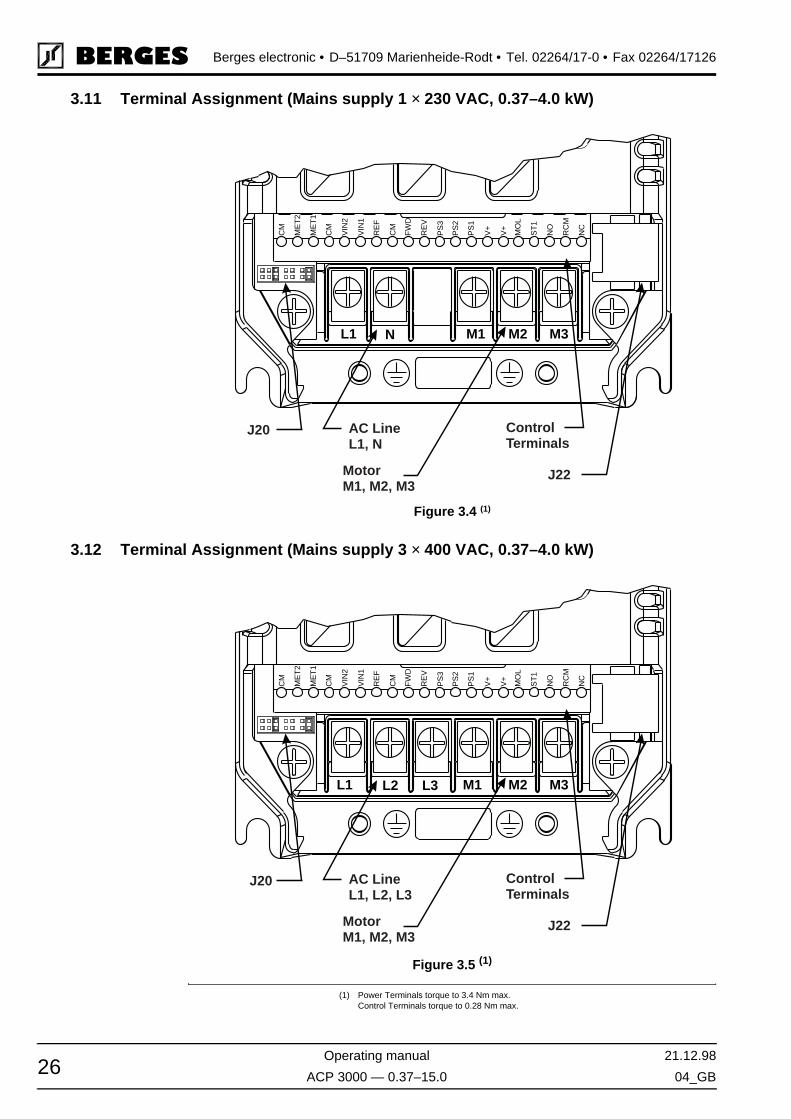
3.11 Terminal Assignment (Mains supply 1 × 230 VAC, 0.37–4.0 kW)
3.12 Terminal Assignment (Mains supply 3 × 400 VAC, 0.37–4.0 kW)
Figure 3.4 (1)
Figure 3.5 (1)
(1) Power Terminals torque to 3.4 Nm max.Control Terminals torque to 0.28 Nm max.
L1 N M1 M2 M3
PS
1
V+
V+
PS
2
PS
3
NC
NO
RC
M
ST
1
MO
L
RE
V
FW
D
CM
RE
F
VIN
1
VIN
2
ME
T1
CM
ME
T2
CM
J20 AC LineL1, N
MotorM1, M2, M3
ControlTerminals
J22
L1 L2 L3 M1 M2 M3
PS
1
V+
V+
PS
2
PS
3
NC
NO
RC
M
ST
1
MO
L
RE
V
FW
D
CM
RE
F
VIN
1
VIN
2
ME
T1
CM
ME
T2
CM
J20 AC LineL1, L2, L3
MotorM1, M2, M3
ControlTerminals
J22

21.12.98 Operating manual
04_GB ACP 3000 — 0.37–15.0 27
Berges electronic • D–51709 Marienheide-Rodt • Tel. 02264/17-0 • Fax 02264/17126
3.13 Terminal Assignment (Mains supply 3 × 400 VAC, 5.5–15.0 kW)
3.14 Remote Keypad/Program Memory Unit Connector (J22)
Connector J22, located on the right side of the ACP 3000 micro-inverter, is used with eitherthe Remote Keypad Unit (XRK01) or Program Memory Unit (XPM01), both sold separately.Both options are battery or AC line adapter powered and can be used with any ACP 3000model to allow remote programming and control of the inverter. The Remote Keypad Unitcan be mounted on another enclosure up to 100 m from the inverter. Programmer optionsallow storage of up to ten separate parameter sets.
3.15 Control Terminal Description
The ACP 3000 series micro-inverter has a 20 position control terminal block. Some func-tions are defined by the setting of jumper J20, while others are defined by programming.Refer to section 7.1 to 7.7 and Figures 3.4 to 3.6.
Figure 3.6 (1)
(1) Power Terminals torque to 3.4 Nm max.Control Terminals torque to 0.28 Nm max.
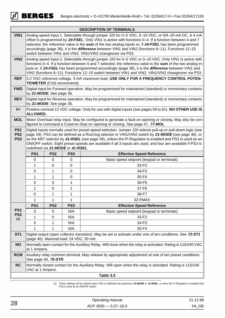
DESCRIPTION OF TERMINALS
CM Circuit Common, isolated from ground.
MET1 Analog meter output 1. Provides a 0 to 10 VDC (1 mA maximum) signal proportional to output frequency, load, or current through setting of 71-METER. May be calibrated while inverter is running by programming 70-MCAL (page 45). Output impedance is 475 Ω.
MET2 Analog meter output 2. Provides a 0 to 20 mA or 4–20 mA signal proportional to output frequency, load, or current through setting of 79-MET2. May be calibrated while inverter is running by programming 78-MCAL2 (page 47). Output impedance is 10 Ω.
CM
ME
T2M
ET1
CM
VIN
2V
IN1
RE
FC
MFW
DR
EV
PS
3P
S2
PS
1V
+V
+M
OL
ST1
NO
RC
MN
C
Control TerminalsJ20 J22
MotorM1, M2, M3
AC LineL1, L2, L3
B- B+ GND GND L3 M1 M2 M3L1 L2
Berges electronic • D–51709 Marienheide-Rodt • Tel. 02264/17-0 • Fax 02264/17126
Operating manual 21.12.98
ACP 3000 — 0.37–15.0 04_GB28
VIN1 Analog speed input 1. Selectable through jumper J20 for 0–5 VDC, 0–10 VDC, or 0/4–20 mA DC. A 4 mA offset is programmed by 24-FSEL. Only VIN1 is active with functions 0–4. If a function between 4 and 7 selected, the reference value is the sum of the two analog inputs or, if 24-FSEL has been programmed accordingly (page 38), it is the difference between VIN1 and VIN2 (functions 8–11). Functions 12–15 switch between VIN1 and VIN2. VIN1/VIN2 changeover via PS3.
VIN2 Analog speed input 2. Selectable through jumper J20 for 0–5 VDC or 0–10 VDC. Only VIN1 is active with functions 0–4. If a function between 4 and 7 selected, the reference value is the sum of the two analog in-puts or, if 24-FSEL has been programmed accordingly (page 38), it is the difference between VIN1 and VIN2 (functions 8–11). Functions 12–15 switch between VIN1 and VIN2. VIN1/VIN2 changeover via PS3.
REF 5.2 VDC reference voltage, 3 mA maximum load. USE ONLY FOR A FREQUENCY CONTROL POTEN-TIOMETER (5 kΩ recommend).
FWD Digital input for Forward operation. May be programmed for maintained (standard) or momentary contacts by 21-MODE. See page 36.
REV Digital input for Reverse operation. May be programmed for maintained (standard) or momentary contacts by 21-MODE. See page 36.
V+ Positive nominal 12 VDC voltage. Only for use with digital inputs (see pages 59 to 61). NO OTHER USE IS ALLOWED.
MOL Motor Overload relay input. May be configured to generate a fault on opening or closing. May also be con-figured to command a Coast-to-Stop on opening or closing. See page 47, 77-MOL.
PS1PS2PS3
Digital inputs normally used for preset speed selection. Jumper J20 selects pull-up or pull-down logic (see page 29). PS3 can be defined as a Run/Jog selector or VIN1/VIN2 switch by 21-MODE (see page 36), or as the ART selector by 41-RSEL (see page 39), unless the PI Regulator is enabled and PS3 is used as an ON/OFF switch. Eight preset speeds are available if all 3 inputs are used, and four are available if PS3 is redefined via 21-MODE or 41-RSEL.
PS1 PS2 PS3 Effective Speed Reference
0 0 0 Basic speed setpoint (keypad or terminals)
1 0 0 33-F2
0 1 0 34-F3
1 1 0 35-F4
0 0 1 36-F5
1 0 1 37-F6
0 1 1 38-F7
1 1 1 32-FMAX
PS1PS2
(1)
PS1 PS2 PS3 Effective Speed Reference
0 0 N/A Basic speed setpoint (keypad or terminals)
1 0 N/A 33-F2
0 1 N/A 34-F3
1 1 N/A 35-F4
ST1 Digital output (open collector transistor). May be set to activate under one of ten conditions. See 72-ST1 (page 46). Maximal load: 24 VDC, 50 mA.
NO Normally open contact for the Auxiliary Relay. Will close when the relay is activated. Rating is 115/240 VAC at 1 Ampere.
RCM Auxiliary relay common terminal. May release by appropriate adjustment at one of ten preset conditions. See page 46, 75-STR.
NC Normally closed contact for the Auxiliary Relay. Will open when the relay is activated. Rating is 115/240 VAC at 1 Ampere.
Table 3.3
(1) These settings will be utilized when PS3 is redefined via parameter 21-MODE or 41-RSEL, or when the PI Regulator is enabled andPS3 is used as an ON/OFF switch.
DESCRIPTION OF TERMINALS

21.12.98 Operating manual
04_GB ACP 3000 — 0.37–15.0 29
Berges electronic • D–51709 Marienheide-Rodt • Tel. 02264/17-0 • Fax 02264/17126
3.16 J20 Configuration
Jumpers J20, on the bottom left edge of the control module (see Figures 3.4–3.6), enablechangeover of analog value specification and the switching logic of the digital control inputs.It has seven (7) positions and two movable shorting jumpers. One jumper selects the ana-log speed reference used and the second jumper selects the active state (High or Low) ofthe digital inputs. A pair of small needle nose pliers will prove useful for moving these jump-ers. REMOVE AC POWER AND WAIT FOR ALL INDICATORS TO GO OUT BEFORECHANGING THIS JUMPERS.
JUMPERSETTINGS
FUNCTION DESCRIPTION
VIN1: 0–10 VDC Terminal input VIN1:This configures the drive to accept an external 0–10 VDC speed reference sig-nal. 24-FSEL selects direct or inverse operation. Input impedance is 95 kΩ.
VIN1: 0–20 mAor 4–20 mA
Terminal input VIN1:This configures the drive for either a 0–20 mA or a 4–20 mA input from an exter-nal source. 0–20 mA or 4–20 mA is selected by 24-FSEL. Input impedance is 250 kΩ.
VIN1: 0–5 VDC Terminal input VIN1:(DEFAULT SETTING) This configures the drive for an external 0–5 VDC signal, or a speed potentiometer powered from the REF terminal on the control terminal strip. 24-FSEL selects direct or inverse operation. Input impedance is 48 kΩ.
VIN2: 0–10 VDC Terminal input VIN2:This configures the drive to accept an external 0–10 VDC speed reference sig-nal. 24-FSEL selects direct or inverse operation. Input impedance is 95 kΩ.
VIN2: 0–5 VDC Terminal input VIN2:This configures the drive for an external 0–5 VDC signal, or a speed potentiom-eter powered from the REF terminal on the control terminal strip. 24-FSEL se-lects direct or inverse operation. Input impedance is 48 kΩ.
Pull-Down Logic This configures the digital inputs for pull-down logic. That is, active when con-nected to terminal CM. Inputs are high, and are pulled low to activate.
Pull-Up Logic (DEFAULT SETTING)This configures the digital inputs for pull-up logic. That is, active when connected to terminal V+, or to an external power supply with it's common connected to CM. Inputs are low and require a positive voltage to activate them. 0 to 3 VDC is IN-ACTIVE, 10 to 24 VDC is ACTIVE.

Berges electronic • D–51709 Marienheide-Rodt • Tel. 02264/17-0 • Fax 02264/17126
Operating manual 21.12.98
ACP 3000 — 0.37–15.0 04_GB30
4 Getting Started
4.1 General Information
Some ACP 3000 Series micro-inverters do not have a digital keypad as standard equip-ment. These models are programmed to operate via the control terminal strip. Use eitheroption XRK01 (Remote Keypad Unit) or XPM01 (Program Memory Unit) to re-program theinverter.
Your ACP 3000 micro-inverter is pre-programmed to run a standard 4-pole AC inductionmotor; in many cases no additional programming is required.
The advanced digital keypad controls all operations of the inverter. The eight input keys al-low “Press and Run” operation of the motor and straight forward programming of the pa-rameters. To simplify the programming further, the parameters are separated into twoProgram Levels:
LEVEL 1 Easily entered by pressing the PROG key at any time. Limits access to themost commonly used parameters for operator convenience.
LEVEL 2 Accesses all parameters including those in Level 1. Used when the more ad-vanced features are needed. It is entered by pressing and holding the SHIFTkey then pressing the PROG key.
Parameters may be only be programmed when the drive is stopped, with the exception of70-MCAL and 78-MCAL2 which may be programmed at any time (see section 5.2).
4.2 Digital Keypad
4.3 Keypad Operation
When 21-MODE is set to 0 or 10, start/stop and speed commands are accepted from thekeypad. The keys are used to operate the inverter as described in section 4.4.
Figure 4.1

21.12.98 Operating manual
04_GB ACP 3000 — 0.37–15.0 31
Berges electronic • D–51709 Marienheide-Rodt • Tel. 02264/17-0 • Fax 02264/17126
4.4 Operation Mode (RUN and STOP Modes)
4.5 Program Mode
KEY FUNCTION
Initiates forward run when pressed momentarily. If the drive is running in reverse when FWD is pressed, it will decelerate to zero speed, change direction, and accelerate to the set speed.
Initiates reverse run when pressed momentarily. If the drive is running in forward when REV is pressed, it will decelerate to zero speed, change direction, and accelerate to the set speed.
Causes Ramp-To-Stop. Programmable to Coast-To-Stop by 41-RSEL.
In the Stop mode, pressing this key increases the desired running speed of the drive. In the Run mode, pressing this key increases the actual running speed of the drive. Setting resolution is 0.05 Hz up to 99.95 Hz and 0.1 Hz above this frequency. The display will scroll at an increased rate after holding the key for five seconds. Pressing SHIFT while holding the UP Arrow bypasses the delay.
In the Stop mode, pressing this key decreases the desired running speed of the drive. In the Run mode, pressing this key decreases the actual running speed of the drive. Setting resolution is 0.05 Hz up to 99.95 Hz and 0.1 Hz above this frequency. The display will scroll at an increased rate after holding the key for five seconds. Pressing SHIFT while holding the DOWN Arrow bypasses the delay.
In the Stop or Run modes, pressing this key will store the selected frequency as the initial operating fre-quency when the inverter is powered up. The frequency is maintained until another frequency is entered.
When the inverter is running, pressing this key accesses the Level 1 parameters for viewing only. Holding SHIFT and then pressing PROG accesses the Level 2 parameters for viewing. Any attempt to program (other than 70-MCAL and 78-MCAL2) results in a display that shows “– – – –”. In Stop mode, programming is allowed in both Level 1 and Level 2. See section 4.5, page 31.
Table 4.1
KEY FUNCTION
When in Stop mode, pressing this key will enter the Program mode at Level 1. Pressing the key at any time while in the Program mode will return the unit to the Operation mode. Pressing and holding SHIFT while pressing PROG will access Level 2. If an Access Code has been invoked, it must be entered to change Data Code. See page 50, 87-ACODE.
In the Program mode, pressing this key will move forward through the successive parameters. If the PRG indicator is flashing it increases the Data Code. The ENTER key must be pressed to store the Data Code.
In the Program mode, pressing this key will move backward through the successive parameter addresses. If the PRG indicator is flashing it decreases the Data Code. The ENTER key must be pressed to store the Data Code.
NOTE:If the PRG indicator is flashing, momentarily pressing and releasing both the UP and DOWN arrows simul-taneously will return the Data Code to factory defaults. Press ENTER to store the new code.
Pressing this key while a parameter is displayed will allow that parameter to have its Data Code changed by use of the UP and DOWN arrow keys. The PRG indicator flashes to show that the parameter can be programmed.
This key must be pressed after the Data Code has been changed to store the new code. The display will show STOred for one second indicating that the Data Code has been entered into memory.
Table 4.2

Berges electronic • D–51709 Marienheide-Rodt • Tel. 02264/17-0 • Fax 02264/17126
Operating manual 21.12.98
ACP 3000 — 0.37–15.0 04_GB32
4.6 Status Indicator
The STATUS indicator consists of two LEDs, one green and one red located in the upperright corner of the control board. They are visible through a lens in the upper right corner ofthe keypad on IP 21 models. The following table defines the STATUS indicator state for thevarious operating conditions of the inverter:
4.7 Description of Displays
The back-lit, LCD display provides information on drive operation and programming. Thefour large 7-segment displays show drive output and programming data. The two smallerdigits are used to indicate parameter numbers in the Program mode. Special symbols anddisplays provide further clarification of drive operation. Figure 4.2 shows all segments dis-played. In normal operation only those segments that are active are displayed.
Table 4.4 lists the special annunciators and their meaning:
STATUS INDICATION OPERATING CONDITION
COLOUR DURATION
Green and Red Continuous Power on, restart (2 Seconds)
Red Continuous Stop, running in torque limit
Green Continuous Run
Green and Red Flashing Running in and out of torque limit
Red Flashing Fault condition, Emergency Stop, line start lock-out, or low-voltage
Green Flashing Running in and out of an overvoltage or undervoltage con-dition
Table 4.3
Figure 4.2
SYMBOL DESCRIPTION
FWD Forward direction commanded
REV Reverse direction commanded
PRG Continuous: Program mode selected.Flashing: Data Code may be changed
SET Inverter is stopped, or is having the running frequency set
OV Inverter is in an overvoltage condition
UV Inverter is in an undervoltage condition
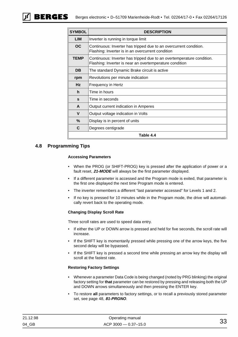
21.12.98 Operating manual
04_GB ACP 3000 — 0.37–15.0 33
Berges electronic • D–51709 Marienheide-Rodt • Tel. 02264/17-0 • Fax 02264/17126
4.8 Programming Tips
Accessing Parameters
• When the PROG (or SHIFT-PROG) key is pressed after the application of power or afault reset, 21-MODE will always be the first parameter displayed.
• If a different parameter is accessed and the Program mode is exited, that parameter isthe first one displayed the next time Program mode is entered.
• The inverter remembers a different “last parameter accessed” for Levels 1 and 2.
• If no key is pressed for 10 minutes while in the Program mode, the drive will automati-cally revert back to the operating mode.
Changing Display Scroll Rate
Three scroll rates are used to speed data entry.
• If either the UP or DOWN arrow is pressed and held for five seconds, the scroll rate willincrease.
• If the SHIFT key is momentarily pressed while pressing one of the arrow keys, the fivesecond delay will be bypassed.
• If the SHIFT key is pressed a second time while pressing an arrow key the display willscroll at the fastest rate.
Restoring Factory Settings
• Whenever a parameter Data Code is being changed (noted by PRG blinking) the originalfactory setting for that parameter can be restored by pressing and releasing both the UPand DOWN arrows simultaneously and then pressing the ENTER key.
• To restore all parameters to factory settings, or to recall a previously stored parameterset, see page 48, 81-PRGNO.
LIM Inverter is running in torque limit
OC Continuous: Inverter has tripped due to an overcurrent condition.Flashing: Inverter is in an overcurrent condition
TEMP Continuous: Inverter has tripped due to an overtemperature condition.Flashing: Inverter is near an overtemperature condition
DB The standard Dynamic Brake circuit is active
rpm Revolutions per minute indication
Hz Frequency in Hertz
h Time in hours
s Time in seconds
A Output current indication in Amperes
V Output voltage indication in Volts
% Display is in percent of units
C Degrees centigrade
Table 4.4
SYMBOL DESCRIPTION

Berges electronic • D–51709 Marienheide-Rodt • Tel. 02264/17-0 • Fax 02264/17126
Operating manual 21.12.98
ACP 3000 — 0.37–15.0 04_GB34
Help
• For Application Assistance, call BERGES electronic at 02264/17-160, 02264/17-102and 02264/17-109.
4.9 Quick Start
This section is for operators with simple applications who would like to get up and runningquickly and with a minimum amount of reading of the manual. Be sure to read sections 4.1through 4.8 before proceeding. In many cases your ACP 3000 will perform perfectly withoutmaking any changes to the factory settings.
A. Perform all procedures for installation as specified in section 3 – Installation.RE-VERIFY THAT THE PROPER VOLTAGE IS CONNECTED TO THE INVERTERBEFORE APPLYING POWER. FAILURE TO DO THIS CAN RESULT IN PERSONALINJURY AND EQUIPMENT FAILURE!
B. Apply AC power to the input terminals. For about two seconds the display will show allsegments active (see Figure 4.2). The STATUS indicator will then turn red (indicating aStop condition) and the display will change to:
C. The factory settings correspond to control via the analog input VIN1. Activate terminalFWD or REV. The FWD and REV keys are thus ineffective. The display will e.g. changeto:
D. Control the VIN1 terminal with 0–5/10 V or 0/4–20 mA. When the display gets to 0.1 Hz,the inverter will start to produce an output. The motor will already begin to run with a cor-respondingly low load. When the motor starts to turn, check the rotation. If the motor isturning in the wrong direction, PRESS STOP, REMOVE AC POWER AND WAIT FORALL INDICATORS TO GO OUT. After the STATUS indicator has gone out, reverse anytwo of the motor leads at M1, M2 or M3.
E. The inverter is preset to run a standard 4-pole AC induction motor to a maximum speedof 50.00 Hz with both Acceleration and Deceleration times set to 3.0 seconds. See sec-tion 9.1, “Parameter Code Summary” for a complete list of all factory settings.
Figure 4.3
Figure 4.4

21.12.98 Operating manual
04_GB ACP 3000 — 0.37–15.0 35
Berges electronic • D–51709 Marienheide-Rodt • Tel. 02264/17-0 • Fax 02264/17126
5 Parameter Configuration and Description
Level 1 – Accesses only basic operator parameters.
Level 2 – Accesses all parameters including those in Level 1.
5.1 Programming
Refer to Figures 4.1 and 5.1. To change the default Data Code in a given parameter:
A. Press the STOP key to stop the inverter if running.
B. Press the PROGram key to enter Level 1 Program mode. To enter Level 2 press andhold the SHIFT key and then the PROGram key. The PRG indicator will turn on.
C. Press the UP/DOWN arrow keys to access the desired parameter. The parameternumber will be displayed in the upper left corner of the digital display.
D. Press the SHIFT key to allow the Data Code to be changed. PRG will starts to blink.
E. Press the UP/DOWN arrows to select the new Data Code.
F. Press the ENTER key to store the new Data Code. The display shows STOred for onesecond.
G. Press the PROGram key to exit the Program mode or the UP/DOWN arrows to select anew parameter.
5.2 Parameter Descriptions
The following section contains functional descriptions of all parameters. The number in the“LEVEL” column indicates the programming level in which access to the parameter in ques-tion is possible. Access to all parameters is possible in level 2 (also to parameter in level1). A “V” means that this parameter only has a view function, while “P” stands for program-mable.
This parameter holds the identification code of the Read Only Memory.
This defines the nominal output current of the inverter and serves as the 100% referencefor all current measurements. Continuous drive capacity is 1.1 times 03-IRAT. Your ACP3000 inverter can provide 110% of this rating continuously without damage or tripping.
Figure 5.1
PARAMETER DESCRIPTION UNIT LEVEL
02-RVLVL – Software Revision 2V
03-IRAT – Inverter Rated Current [A] 2V

Berges electronic • D–51709 Marienheide-Rodt • Tel. 02264/17-0 • Fax 02264/17126
Operating manual 21.12.98
ACP 3000 — 0.37–15.0 04_GB36
This defines the most recent faults. The two left most digits are the fault code, and the rightmost is elapsed time in 0.1 hr increments since the last restart of the drive, 0.9 hours max.See chapter 8.2, page 62.
Inverter output frequency (Hz) applied to the motor.
◊ Value range: 0.00–400.0 Hz
Motor output voltage calculated as a percent of applied line input voltage.
◊ Value range: 0–100% of the mains voltage
Motor phase current computed to an accuracy of ±20%.
◊ Value range: 0.00–60.00 A
True part of motor current. Output current measurement with motor power factor applied.Accuracy is ±20%. Load reading is positive in motoring mode, and negative in regenerativemode.
◊ Value range: 0–200% of 03-IRAT
Inverter heatsink temperature. The inverter will turn off when this temperature exceeds itsmaximum allowed temperature. Accuracy is ±3 °C.
◊ Value range: 0.00–110.0 °C
The 21-MODE parameter defines the source for speed reference and Run/Stop control in-put.
MODELNUMBER
VALUE OF 03-IRAT MODELNUMBER
VALUE OF 03-IRAT
3300-3 2.0 A 3602-2 5.5 A
3300-5 3.6 A 3603-0 9.0 A
3300-7 6.8 A 3604-0 9.0 A
3301-1 6.8 A 3605-5 13.0 A
3301-5 9.6 A 3607-5 18.0 A
3302-2 15.2 A 3611-0 24.0 A
3600-7 2.0 A 3615-0 30.0 A
3601-5 3.7 A
Table 5.1
07-FLT3 – Last Fault 1V
08-FLT2 – Second Fault 2V
09-FLT1 – First Fault 2V
12-FOUT – Motor Output Frequency [Hz] 1V
13-VOUT – Motor Output Voltage [%] 1V
14-IOUT – Motor Output Current [A] 1V
15-LOAD – Inverter Load [%] 1V
17-TEMP – Inverter Temperature [°C] 1V
21-MODE – Input Mode 1P

21.12.98 Operating manual
04_GB ACP 3000 — 0.37–15.0 37
Berges electronic • D–51709 Marienheide-Rodt • Tel. 02264/17-0 • Fax 02264/17126
NOTES:
1) VIN1/VIN2 changeover via PS3.
2) Data codes 6 up to 9 select the ACP EMOP control programs. With codes 6 or 7 (EMOP)selected, commanded output frequency returns to 31-FMIN when the drive is stopped.With codes 8 or 9 (EMOP1) selected, commanded output frequency remains at the pre-vious setpoint. See table above for proper usage.
◊ Value range: 0–11 Default: 3
EMOP/EMOP1 Control Terminal Logic Table(Electronic Motor Potentiometer)
DATACODE
SPEED CONTROL START/STOP CONTROL
0 Keypad Keypad (FWD only)
1 VIN Terminals 1) Keypad (FWD only)
2 Keypad Terminals (2-Wire Maintained Contact)
3 VIN Terminals 1) Terminals (2-Wire Maintained Contact)
4 Keypad Terminals(3-Wire Momentary, RUN/JOG via PS3)
5 VIN Terminals Terminals(3-Wire Momentary, RUN/JOG via PS3)
6 EMOP 2)
(Electronic motor potentiometer)
Terminals
(2-Wire, see section 7.7, page 61 and table below)
7 EMOP 2)
(Electronic motor potentiometer)
Terminals
(3-Wire, see section 7.7, page 61 and table below)
8 EMOP1 2)
(Electronic motor potentiometer)
Terminals
(2-Wire, see section 7.7, page 61 and table below)
9 EMOP1 2)
(Electronic motor potentiometer)
Terminals
(3-Wire, see section 7.7, page 61 and table below)
10 Keypad Keypad (FWD and REV)
11 VIN Terminals 1) Keypad (FWD and REV)
DESCRIPTION FWD REV PS1 PS2
STOP 0 0 X X
Speed = 0 1 1 X X
FWD Decrease 1 0 1 X
FWD Hold 1 0 0 0
FWD Increase 1 0 0 1
REV Decrease 0 1 1 X
REV Hold 0 1 0 0
REV Increase 0 1 0 1
0 = inactive 1 = active X = ignored

Berges electronic • D–51709 Marienheide-Rodt • Tel. 02264/17-0 • Fax 02264/17126
Operating manual 21.12.98
ACP 3000 — 0.37–15.0 04_GB38
NOTE:
DIRECT = Maximum output (32-FMAX) at maximum input.INVERSE = Minimum output (31-FMIN) at maximum input.
◊ Value range: 0–19 Default: 0
Sets the minimum frequency to the motor. Programmable from 0.00 to 99.95 Hz in 0.05 Hzincrements and 0.1 Hz above this frequency. Minimum programmable output frequency is0.00 Hz.
◊ Value range: 0.00–400.0 Hz Default: 0.00 Hz
Sets the maximum frequency to the motor. Programmable from 20.00 to 99.95 Hz in 0.05Hz increments and 0.1 Hz above this frequency. Consult motor manufacturer if frequencyis in excess of motor nameplate rating.
◊ Value range: 20.00–400.0 Hz Default: 50.00 Hz
Programmable from 0.00 to 99.95 Hz in 0.05 Hz increments and 0.1 Hz above this frequen-cy. Selected with input terminals PS1, PS2 and PS3 (see section 3.15 and 7.7, page 27 and61). May be set to a frequency greater than 32-FMAX, but the output will not exceed 32-FMAX when running. Consult motor manufacturer if frequency is in excess of motor name-plate rating.
◊ 33-F2 Value range: 0.00–400.0 Hz Default: 5.00 Hz34-F3 Value range: 0.00–400.0 Hz Default: 20.00 Hz35-F4 Value range: 0.00–400.0 Hz Default: 40.00 Hz36-F5 Value range: 0.00–400.0 Hz Default: 50.00 Hz37-F6 Value range: 0.00–400.0 Hz Default: 0.00 Hz38-F7 Value range: 0.00–400.0 Hz Default: 0.00 Hz
24-FSEL – Speed Setpoint Selector 2P
DATARANGE
DESCRIPTION
0–3 With these settings, only VIN1 is active. Selects the speed setpoint charac-teristics and the offset if required (see following table). See chapter 3.16, “J20 Configuration”, page 29.
4–7 Defines reference as VIN1 plus VIN2. VIN1 can be adapted to suit customer requirements (see following table).
8–11 Defines reference as VIN1 minus VIN2. VIN1 can be adapted to suit custom-er requirements (see following table).
12–15 Changeover for VIN1/VIN2:PS3 = 0 ⇒ VIN1 active.PS3 = 1 ⇒ VIN2 active.VIN1 can be adapted to suit customer requirements (see following table).
VIN1 ADJUSTMENT
DATA CODES OPERATION OFFSET INPUT SIGNAL VIN1
0, 4, 8, 12 DIRECT None 0–10 VDC, 0–5 VDC, 0–20 mA
1, 5, 9, 13 INVERSE None 0–10 VDC, 0–5 VDC, 0–20 mA
2, 6, 10, 14 DIRECT 20% 4–20 mA
3, 7, 11, 15 INVERSE 20% 4–20 mA
31-FMIN – Minimum Frequency [Hz] 1P
32-FMAX – Maximum Frequency [Hz] 1P
33-F2 to 38-F7 – Preset Frequencies [Hz] 2P

21.12.98 Operating manual
04_GB ACP 3000 — 0.37–15.0 39
Berges electronic • D–51709 Marienheide-Rodt • Tel. 02264/17-0 • Fax 02264/17126
This parameter sets the lowest frequency that the drive will decelerate to when in torquelimit. If the load is large enough to drive the inverter below this threshold, the drive will tripon overcurrent. The rate of deceleration is set by 46-DECTL. Programmable from 0.00 to400.00 Hz. Factory set for 10.00 Hz. To disable Torque Limit, set this to a Data Code great-er than 32-FMAX.
◊ Value range: 0.00–400.0 Hz Default: 10.00 Hz
Selects the Acceleration and Deceleration ramps that control the motor and also enablesthe coast-to-stop function.
◊ Value range: 0–7 Default: 0
Sets the length of time to accelerate from 0 Hz to 32-FMAX. To be programmed in stepsfrom 0.05 seconds to 99,95 seconds and, in excess of this amount, in steps of 0.1 second.Extremely short acceleration times may result in nuisance fault trips (see 41-RSEL, page39).
◊ Value range: 0.10–600.0 s Default: 3.00 s
Sets the length of time to decelerate from 32-FMAX to 0 Hz. To be programmed in stepsfrom 0.05 seconds to 99,95 seconds and, in excess of this amount, in steps of 0.1 second.Extremely short deceleration times may result in nuisance fault trips (see 41-RSEL, page39). Higher braking performance can be achieved with an additional external braking chop-per (option BC6000).
◊ Value range: 0.10–600.0 s Default: 3.00 s
39-FTL – Minimum Frequency in Torque Limit [Hz] 2P
41-RSEL – Ramp Selector 2P
DATACODE
DEFINITION
0 Ramp-to-stop with 42-ACC1 and 43-DEC1 active.
1 42-ACC1/43-DEC1 active in Forward, 44-ACC2/45-DEC2 active in Reverse.
2 42-ACC1/43-DEC1 active when the output frequency is less than preset fre-quency 37-F6, 44-ACC2/45-DEC2 active when output frequency is equal to or greater than 37-F6.
3 When 21-MODE is set to 2, 3, or 6, PS3 is re-defined as the Alternate Ramp Time (ART) selector, unless the PI Controller is utilized. When this terminal is ac-tive, 44-ACC2 and 45-DEC2 are active. Note that PS3 cannot be used as a pre-set speed selector when 41-RSEL is set to 3 or when the PI Controller is enabled and PS3 is used as an ON/OFF switch. (See Table 3.3 on page 28; also see 21-MODE on page 36.)
4 Same as 0, except coast-to-stop is selected when stopping.
5 Same as 1, except coast-to-stop is selected when stopping.
6 Same as 2, except coast-to-stop is selected when stopping.
7 Same as 3, except coast-to-stop is selected when stopping.
42-ACC1 – Acceleration Time 1 [s] 1P
43-DEC1 – Deceleration Time 1 [s] 1P

Berges electronic • D–51709 Marienheide-Rodt • Tel. 02264/17-0 • Fax 02264/17126
Operating manual 21.12.98
ACP 3000 — 0.37–15.0 04_GB40
Alternate Acceleration Ramp. Same adjustment range as of 42-ACC1 (see 41-RSEL, page39).
◊ Value range: 0.10–600.0 s Default: 1.00 s
Alternate Deceleration Ramp. Same adjustment range as of 43-DEC1 (see 41-RSEL, page39).
◊ Value range: 0.10–600.0 s Default: 1.00 s
This parameter sets the deceleration rate when the drive is operating in torque limit mode.Programmable from 0.10 to 30.00 seconds. It also serves as the acceleration rate when thedrive is in torque limit due to a regenerative condition (see also 39-FTL, page 39.
◊ Value range: 0.10–30.00 s Default: 1.00 s
This is the time in seconds that DC current will be applied to the motor windings with thefollowing conditions:
Data Code = 0.00 s:
DC braking disabled in all modes.
Data Code = 0.05–4.95 s (Timed DC braking):
1. In terminal strip Stop/Start, when both FWD and REV terminals are active.
2. In FWD or REV run mode and the speed reference is reduced to less than 0.1 Hz.
3. A Stop command is given and the output frequency decelerates to less than 0.1 Hz.
Data Code = 5.00 s (Continuous DC braking):
1. In terminal strip Start/Stop, as long as both FWD and REV terminals are held active.
2. In FWD or REV run mode and the speed reference is reduced to less than 0.1 Hz.
3. There is no DC braking after a normal decelerate to stop.
◊ Value range: 0.00–5.00 s Default: 0.20 s
This controls the amount of DC voltage applied to the motor windings by 47-DCBRK. Pro-grammable from 0.00 to 15.00% of the setting of 52-BOOST.
If DC Braking is used as a holding brake, excessive motor heating may result.
◊ Value range: 0.00–15.00% Default: 2/3 of 52-BOOST (%)
Three V/Hz characteristics (constant torque, pump and fan curves) and two starting torqueboost features may be selected.
44-ACC2 – Acceleration Time 2 [s] 2P
45-DEC2 – Deceleration Time 2 [s] 2P
46-DECTL – Deceleration Time in Torque Limit [s] 2P
47-DCBRK – DC Brake Time [s] 2P
48-DCVLT – DC Brake Voltage [%] 2P
51-VSEL – V/Hz Characteristic Selector 2P
DATACODE
DESCRIPTION
0 Linear V/Hz, with Auto-Boost, used with constant torque applications. With Auto-Boost, the optimum boost will be selected depending on load and motor condi-tions, parameter 52-BOOST sets the maximum boost applied.
ATTENTION!

21.12.98 Operating manual
04_GB ACP 3000 — 0.37–15.0 41
Berges electronic • D–51709 Marienheide-Rodt • Tel. 02264/17-0 • Fax 02264/17126
◊ Value range: 0–5 Default: 0
This parameter increases motor voltage at low speed as a percent of nominal voltage toincrease the starting torque of the motor. Voltage boost will linearly decrease with increas-ing speed. Default Boost settings vary between models.
Care must be exercised with this adjustment. Too much boost may cause excessivemotor currents and motor heating. Use only as much boost as is necessary to startthe motor. AUTO-BOOST may be selected at parameter 51-VSEL to provide the opti-mum value of boost to suit the load automatically. Some 2-pole (3000 RPM synchro-nous speed) have proven to require less than the default value of 52-BOOST.
◊ Value range: 0.00–25.00% Default: 8.00%
1 Linear V/Hz, with constant boost fixed by 52-BOOST.
2 Mixed (linear/quadratic) V/Hz, with Auto-Boost, typical of pumping applications.
3 Mixed V/Hz, with constant boost fixed by 52-BOOST.
4 Quadratic V/Hz, with Auto-Boost, for fan-law applications.
5 Quadratic V/Hz, with constant boost fixed by 52-BOOST.
Figure 5.2
52-BOOST – Voltage Boost [%] 1P
DATACODE
DESCRIPTION
ATTENTION!

Berges electronic • D–51709 Marienheide-Rodt • Tel. 02264/17-0 • Fax 02264/17126
Operating manual 21.12.98
ACP 3000 — 0.37–15.0 04_GB42
This parameter is used to set the frequency at which full voltage is delivered to the motor.Thereby, the output volts/hertz ratio of the inverter is adjusted. Programmable from 26.00to 400.0 Hz. It is factory set to the base frequency of the motor, which is 50 Hz for mostEuropean made induction motors. Setting FKNEE to a higher value can reduce motor loss-es at low frequencies.
◊ Value range: 26.00–400.0 Hz Default: 50.00 Hz
This parameter sets the range of frequencies (above and below) associated with each ofthe skip frequencies. Skip bands are used to avoid mechanical resonances in a drive sys-tem. The deviation is adjustable in 0.05 Hz increments from 0.20 Hz to 20.00 Hz. The fac-tory setting is 1.00 Hz equating to an overall 2 Hz band.
◊ Value range: 0.20–20.00 Hz Default: 1.00 Hz
These three (3) parameters set the center frequency of the skip bands over which normaloperation will not be allowed. The inverter will ramp through these frequencies, but not set-tle on them. Programmable from 0.00 to 99.95 Hz in 0.05 Hz increments and 0.1 Hz abovethis frequency.
◊ Value range: 0.00–400.0 Hz Default: 0.00 Hz
This sets the voltage the inverter delivers to the motor terminals at the setting of 53-FKNEE.
230 V models are programmable from 185 to 240 volts, and 400 V models from 370 to 480volts. The inverter attempts to regulate the output voltage with a changing input voltage tobetter than 5%.
◊ Value ranges: 185–240 V; 370–480 V Default: 230 or 400 V
-If the inverter is used to control a motor that is significantly smaller than the drive rating,the motor may draw excessive current in an unloaded condition. This will be evident by a15-LOAD reading that is high when the motor is unloaded and reduces when a load is ap-plied. If this condition occurs, adjust parameter 5B-MSAT, in small increments, to a lowerpercentage until parameter 15-LOAD reads 30–45% in an unloaded condition. ConsultBERGES for more information.
◊ Value range: 15–80% Default: 47%
53-FKNEE – V/Hz Knee Frequency [Hz] 2P
54-SKBND – Skip Frequency Hysteresis Band [Hz] 2P
55-SK1 – Skip Frequency 1 [Hz] 2P
56-SK2 – Skip Frequency 2 [Hz] 2P
57-SK3 – Skip Frequency 3 [Hz] 2P
59-MVOLT – Rated Motor Voltage [V] 2P
5B-MSAT – Motor Saturation Level [%] 2P
61-LTLF – Load Torque Limit Forward [%] 2P
62-LTLR – Load Torque Limit Reverse [%] 2P
63-RTLF – Regenerative Torque Limit Forward [%] 2P
64-RTLR – Regenerative Torque Limit Reverse [%] 2P
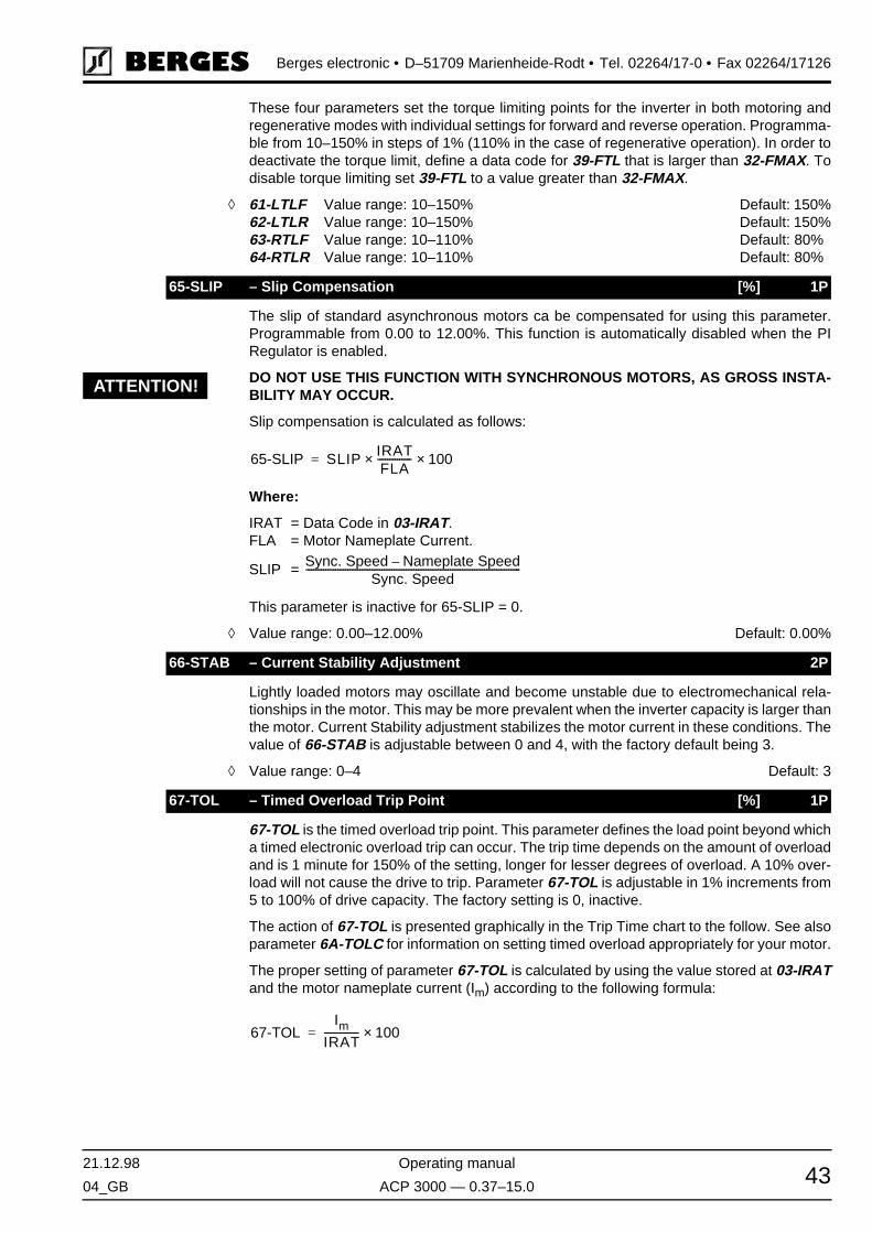
21.12.98 Operating manual
04_GB ACP 3000 — 0.37–15.0 43
Berges electronic • D–51709 Marienheide-Rodt • Tel. 02264/17-0 • Fax 02264/17126
These four parameters set the torque limiting points for the inverter in both motoring andregenerative modes with individual settings for forward and reverse operation. Programma-ble from 10–150% in steps of 1% (110% in the case of regenerative operation). In order todeactivate the torque limit, define a data code for 39-FTL that is larger than 32-FMAX. Todisable torque limiting set 39-FTL to a value greater than 32-FMAX.
◊ 61-LTLF Value range: 10–150% Default: 150%62-LTLR Value range: 10–150% Default: 150%63-RTLF Value range: 10–110% Default: 80%64-RTLR Value range: 10–110% Default: 80%
The slip of standard asynchronous motors ca be compensated for using this parameter.Programmable from 0.00 to 12.00%. This function is automatically disabled when the PIRegulator is enabled.
DO NOT USE THIS FUNCTION WITH SYNCHRONOUS MOTORS, AS GROSS INSTA-BILITY MAY OCCUR.
Slip compensation is calculated as follows:
Where:
IRAT = Data Code in 03-IRAT.FLA = Motor Nameplate Current.
SLIP =
This parameter is inactive for 65-SLIP = 0.
◊ Value range: 0.00–12.00% Default: 0.00%
Lightly loaded motors may oscillate and become unstable due to electromechanical rela-tionships in the motor. This may be more prevalent when the inverter capacity is larger thanthe motor. Current Stability adjustment stabilizes the motor current in these conditions. Thevalue of 66-STAB is adjustable between 0 and 4, with the factory default being 3.
◊ Value range: 0–4 Default: 3
67-TOL is the timed overload trip point. This parameter defines the load point beyond whicha timed electronic overload trip can occur. The trip time depends on the amount of overloadand is 1 minute for 150% of the setting, longer for lesser degrees of overload. A 10% over-load will not cause the drive to trip. Parameter 67-TOL is adjustable in 1% increments from5 to 100% of drive capacity. The factory setting is 0, inactive.
The action of 67-TOL is presented graphically in the Trip Time chart to the follow. See alsoparameter 6A-TOLC for information on setting timed overload appropriately for your motor.
The proper setting of parameter 67-TOL is calculated by using the value stored at 03-IRATand the motor nameplate current (Im) according to the following formula:
65-SLIP – Slip Compensation [%] 1P
66-STAB – Current Stability Adjustment 2P
67-TOL – Timed Overload Trip Point [%] 1P
ATTENTION!
65-SLIP SLIP IRATFLA
--------------× 100×=
Sync. Speed Nameplate Speed–Sync. Speed
----------------------------------------------------------------------------------------
67-TOLIm
IRAT-------------- 100×=
Berges electronic • D–51709 Marienheide-Rodt • Tel. 02264/17-0 • Fax 02264/17126
Operating manual 21.12.98
ACP 3000 — 0.37–15.0 04_GB44
Motor protection by means of the parameter 67-TOL is recommended for single motordrives.
When operating multiple motors from a single inverter, use a separate external motorprotection device on each motor and set parameter 67-TOL to it's factory setting of0 (disabled).
◊ Value range: 0–100% Default: 0%
THIS FUNCTION REQUIRES MAINTAINED CONTACT RUN/STOP CONTROL TOFUNCTION.IF THE SETTING OF 68-NRST HAS BEEN EXCEEDED AND FAULT F10 IS DIS-PLAYED, RESETTING THE FAULT WILL RESULT IN AN IMMEDIATE START. ENSURETHAT AUTOMATIC RESTARTING WILL NOT CAUSE INJURY TO PERSONNEL ORDAMAGE TO EQUIPMENT.
The inverter will automatically perform a reset, after delay set by 69-DRST, from 1 to 8 timeswhen any fault trip with a code of F11 and greater has occurred. If the FWD or REV terminalis still active (2-wire operation) the inverter will attempt a restart (see 21-MODE and section7.2). The count will reset if a another fault is not incurred within 10 minutes. If the pro-grammed count is exceeded within 10 minutes, the inverter will not restart, but will displaya fault trip message F10. RESETTING THE FAULT CAN RESULT IN INSTANT START-ING. SEE WARNING ABOVE.
This function is inactive for 68-NRST = 0.
◊ Value range: 0–8 Default: 0
After a fault trip of F11 or greater has occurred, and 68-NRST is greater than zero, the in-verter will wait for the specified number of seconds before attempting a restart. Program-mable from 0.00 to 60.00 seconds in 0.05 second increments. Restart will be controlled bythe setting of 82-START.
◊ Value range: 0.00–60.00 s Default: 0.00 s
Figure 5.3Percent Load
68-NRST – Trip Restart Number 2P
69-DRST – Restart Delay Time [s] 2P
ATTENTION!
21.12.98 Operating manual
04_GB ACP 3000 — 0.37–15.0 45
Berges electronic • D–51709 Marienheide-Rodt • Tel. 02264/17-0 • Fax 02264/17126
6A-TOLC works in conjunction with 67-TOL to customize the overload characteristics of theinverter to the driven motor. Refer to the graphic presented with parameter 67 for a morein-depth understanding of this parameter.
Data codes “0” through “3” provide for the use of a “standard” motor that typically has a lim-ited continuous constant torque operating speed range. With these data codes, the degreeof overload permitted by the drive depends on the output frequency. Lesser degrees ofoverload are permitted at lower speeds.
Data codes “4” through “7” provide for the use of an “inverter duty” motor that has a moreextensive continuous constant torque operating speed range. With these data codes, theoverload performance follows the curve designated “>40 Hz” regardless of operating fre-quency.
As you adjust between “0” & “3” and “4” & “7”, you get various inverse time characteristics.Data codes “0” and “4” give you the characteristic depicted by the scale designated “C”.Data codes “1” and “5” work on scale “B” and codes “2” and “6” on scale “A”. With datacodes “3” and “7”, the parameter 67-TOL works as an adjustable electronic “shear pin” withno inverse time characteristic.
* Trip time is at 150% of 67-TOL setting.** Trip time is at 110% of 67-TOL setting.
◊ Value range: 0–7 Default: 0
This parameter adjusts the meter output value at terminal MET1. The setting range is 0–255. 70-MCAL can be programmed while the inverter is running.
Factory default is for 10 VDC at terminal MET1, at nominal full scale output.
◊ Value range: 0–255 Default: 210
This parameter selects the analog output signal to be indicated at terminal MET1. The fac-tory full scale setting is 10 VDC but can be changed using parameter 70-MCAL.
6A-TOLC – Timed Overload Characteristic 2P
DATACODE
TRIPPING CHARACTERISTIC TRIP TIME (s) SCALE(Fig. 5.3)
MOTOR TYPE
0 Normal – Reduced threshold below 40 Hz * 60 C Standard Induction
1 Medium – Reduced threshold below 40 Hz * 30 B Standard Induction
2 Fast – Reduced threshold below 40 Hz * 6 A Standard Induction
3 “Shear Pin” – Reduced threshold below 40 Hz ** 0 – Standard Induction
4 Normal – Constant torque * 60 C Inverter Duty
5 Medium – Constant torque * 30 B Inverter Duty
6 Fast – Constant torque * 6 A Inverter Duty
7 “Shear Pin” – Constant torque ** 0 – Inverter Duty
70-MCAL – Analog Meter Output Calibration MET1 1P
71-METER – Analog Meter Output Selector MET1 1P
DATACODE
DESCRIPTION
0 Output off.
1 Output proportional to output frequency (12-FOUT), with full scale at 32-FMAX.
2 Output proportional to output current (14-IOUT), with full scale at 200% of rated current.
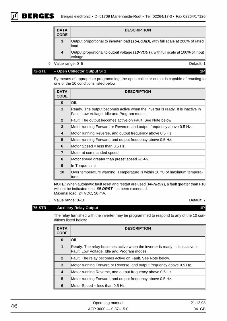
Berges electronic • D–51709 Marienheide-Rodt • Tel. 02264/17-0 • Fax 02264/17126
Operating manual 21.12.98
ACP 3000 — 0.37–15.0 04_GB46
◊ Value range: 0–5 Default: 1
By means of appropriate programming, the open collector output is capable of reacting toone of the 10 conditions listed below.
NOTE: When automatic fault reset and restart are used (68-NRST), a fault greater than F10will not be indicated until 69-DRST has been exceeded.Maximal load: 24 VDC, 50 mA.
◊ Value range: 0–10 Default: 7
The relay furnished with the inverter may be programmed to respond to any of the 10 con-ditions listed below:
3 Output proportional to inverter load (15-LOAD), with full scale at 200% of rated load.
4 Output proportional to output voltage (13-VOUT), with full scale at 100% of input voltage.
72-ST1 – Open Collector Output ST1 1P
DATACODE
DESCRIPTION
0 Off.
1 Ready. The output becomes active when the inverter is ready. It is inactive in Fault, Low Voltage, Idle and Program modes.
2 Fault. The output becomes active on Fault. See Note below.
3 Motor running Forward or Reverse, and output frequency above 0.5 Hz.
4 Motor running Reverse, and output frequency above 0.5 Hz.
5 Motor running Forward, and output frequency above 0.5 Hz.
6 Motor Speed = less than 0.5 Hz.
7 Motor at commanded speed.
8 Motor speed greater than preset speed 36-F5.
9 In Torque Limit.
10 Over temperature warning. Temperature is within 10 °C of maximum tempera-ture.
75-STR – Auxiliary Relay Output 1P
DATACODE
DESCRIPTION
0 Off.
1 Ready. The relay becomes active when the inverter is ready. It is inactive in Fault, Low Voltage, Idle and Program modes.
2 Fault. The relay becomes active on Fault. See Note below.
3 Motor running Forward or Reverse, and output frequency above 0.5 Hz.
4 Motor running Reverse, and output frequency above 0.5 Hz.
5 Motor running Forward, and output frequency above 0.5 Hz.
6 Motor Speed = less than 0.5 Hz.
DATACODE
DESCRIPTION
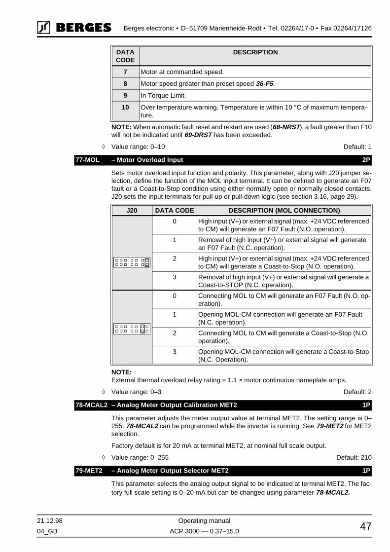
21.12.98 Operating manual
04_GB ACP 3000 — 0.37–15.0 47
Berges electronic • D–51709 Marienheide-Rodt • Tel. 02264/17-0 • Fax 02264/17126
NOTE: When automatic fault reset and restart are used (68-NRST), a fault greater than F10will not be indicated until 69-DRST has been exceeded.
◊ Value range: 0–10 Default: 1
Sets motor overload input function and polarity. This parameter, along with J20 jumper se-lection, define the function of the MOL input terminal. It can be defined to generate an F07fault or a Coast-to-Stop condition using either normally open or normally closed contacts.J20 sets the input terminals for pull-up or pull-down logic (see section 3.16, page 29).
NOTE:External thermal overload relay rating = 1.1 × motor continuous nameplate amps.
◊ Value range: 0–3 Default: 2
This parameter adjusts the meter output value at terminal MET2. The setting range is 0–255. 78-MCAL2 can be programmed while the inverter is running. See 79-MET2 for MET2selection.
Factory default is for 20 mA at terminal MET2, at nominal full scale output.
◊ Value range: 0–255 Default: 210
This parameter selects the analog output signal to be indicated at terminal MET2. The fac-tory full scale setting is 0–20 mA but can be changed using parameter 78-MCAL2.
7 Motor at commanded speed.
8 Motor speed greater than preset speed 36-F5.
9 In Torque Limit.
10 Over temperature warning. Temperature is within 10 °C of maximum tempera-ture.
77-MOL – Motor Overload Input 2P
J20 DATA CODE DESCRIPTION (MOL CONNECTION)
0 High input (V+) or external signal (max. +24 VDC referenced to CM) will generate an F07 Fault (N.O. operation).
1 Removal of high input (V+) or external signal will generate an F07 Fault (N.C. operation).
2 High input (V+) or external signal (max. +24 VDC referenced to CM) will generate a Coast-to-Stop (N.O. operation).
3 Removal of high input (V+) or external signal will generate a Coast-to-STOP (N.C. operation).
0 Connecting MOL to CM will generate an F07 Fault (N.O. op-eration).
1 Opening MOL-CM connection will generate an F07 Fault (N.C. operation).
2 Connecting MOL to CM will generate a Coast-to-Stop (N.O. operation).
3 Opening MOL-CM connection will generate a Coast-to-Stop (N.C. Operation).
78-MCAL2 – Analog Meter Output Calibration MET2 1P
79-MET2 – Analog Meter Output Selector MET2 1P
DATACODE
DESCRIPTION

Berges electronic • D–51709 Marienheide-Rodt • Tel. 02264/17-0 • Fax 02264/17126
Operating manual 21.12.98
ACP 3000 — 0.37–15.0 04_GB48
◊ Value range: 0–15 Default: 3
This parameter allows for storing and resetting parameters and activating special functions.The function will be executed upon exiting the Program mode:
◊ Value range: 0–9999 Default: 0
Controls the operation of line start lock-out and/or Auto-Start into a rotating motor. Addition-ally enables or disables both the STOP key as an E-Stop when operating from the terminalstrip and the Stop function due to a disconnection of a remote device connected to the drivethrough connector J22. See section 8.1 for special display indications used with this param-eter.
NOTE: STARTING INTO A ROTATING MOTOR.When this function is selected, the inverter will attempt to run the motor at 50 Hz output andreduced voltage. It then lowers that frequency until output current is minimized and the mo-tor and frequency are synchronized.
ENSURE THAT THIS OPERATION WILL NOT CAUSE INJURY TO PERSONNEL ORDAMAGE TO EQUIPMENT.
◊ Value range: 0–11 Default: 1
DATACODE
OUTPUTRANGE
DESCRIPTION
0 – Output off.
1 0–20 mA DC Output proportional to output frequency (12-FOUT), with full scale at 32-FMAX.
2 0–20 mA DC Output proportional to output current (14-IOUT), with full scale at 200% of rated current.
3 0–20 mA DC Output proportional to inverter load (15-LOAD), with full scale at 200% of rated load.
4 – Output proportional to output voltage; full scale = input line volt-age. Meter calibration must be set to 189 for this option.
11 4–20 mA DC Output proportional to output frequency (12-FOUT), with full scale at 32-FMAX.
12 4–20 mA DC Output proportional to output current (14-IOUT), with full scale at 200% of rated current.
13 4–20 mA DC Output proportional to inverter load (15-LOAD), with full scale at 200% of rated load.
14 – Output proportional to output voltage; full scale input line voltage.
81-PRGNO – Special Program 2P
DATACODE
DESCRIPTION
0 Standard Program
1 Reset parameters to factory settings (Display = SETP)
2 Store customer parameter settings (Display = STOC)
3 Recall customer parameter settings (Display = SETC)
80–95 Enables the PI Controller; see chapter 6 on page 51 for further information.
82-START – Start Options 2P
ATTENTION!
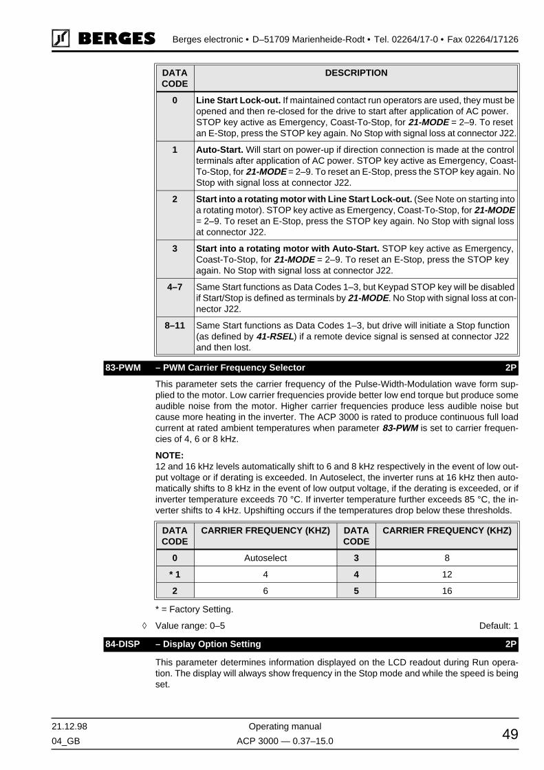
21.12.98 Operating manual
04_GB ACP 3000 — 0.37–15.0 49
Berges electronic • D–51709 Marienheide-Rodt • Tel. 02264/17-0 • Fax 02264/17126
This parameter sets the carrier frequency of the Pulse-Width-Modulation wave form sup-plied to the motor. Low carrier frequencies provide better low end torque but produce someaudible noise from the motor. Higher carrier frequencies produce less audible noise butcause more heating in the inverter. The ACP 3000 is rated to produce continuous full loadcurrent at rated ambient temperatures when parameter 83-PWM is set to carrier frequen-cies of 4, 6 or 8 kHz.
NOTE:12 and 16 kHz levels automatically shift to 6 and 8 kHz respectively in the event of low out-put voltage or if derating is exceeded. In Autoselect, the inverter runs at 16 kHz then auto-matically shifts to 8 kHz in the event of low output voltage, if the derating is exceeded, or ifinverter temperature exceeds 70 °C. If inverter temperature further exceeds 85 °C, the in-verter shifts to 4 kHz. Upshifting occurs if the temperatures drop below these thresholds.
* = Factory Setting.
◊ Value range: 0–5 Default: 1
This parameter determines information displayed on the LCD readout during Run opera-tion. The display will always show frequency in the Stop mode and while the speed is beingset.
DATACODE
DESCRIPTION
0 Line Start Lock-out. If maintained contact run operators are used, they must be opened and then re-closed for the drive to start after application of AC power. STOP key active as Emergency, Coast-To-Stop, for 21-MODE = 2–9. To reset an E-Stop, press the STOP key again. No Stop with signal loss at connector J22.
1 Auto-Start. Will start on power-up if direction connection is made at the control terminals after application of AC power. STOP key active as Emergency, Coast-To-Stop, for 21-MODE = 2–9. To reset an E-Stop, press the STOP key again. No Stop with signal loss at connector J22.
2 Start into a rotating motor with Line Start Lock-out. (See Note on starting into a rotating motor). STOP key active as Emergency, Coast-To-Stop, for 21-MODE = 2–9. To reset an E-Stop, press the STOP key again. No Stop with signal loss at connector J22.
3 Start into a rotating motor with Auto-Start. STOP key active as Emergency, Coast-To-Stop, for 21-MODE = 2–9. To reset an E-Stop, press the STOP key again. No Stop with signal loss at connector J22.
4–7 Same Start functions as Data Codes 1–3, but Keypad STOP key will be disabled if Start/Stop is defined as terminals by 21-MODE. No Stop with signal loss at con-nector J22.
8–11 Same Start functions as Data Codes 1–3, but drive will initiate a Stop function (as defined by 41-RSEL) if a remote device signal is sensed at connector J22 and then lost.
83-PWM – PWM Carrier Frequency Selector 2P
DATACODE
CARRIER FREQUENCY (KHZ) DATACODE
CARRIER FREQUENCY (KHZ)
0 Autoselect 3 8
* 1 4 4 12
2 6 5 16
84-DISP – Display Option Setting 2P
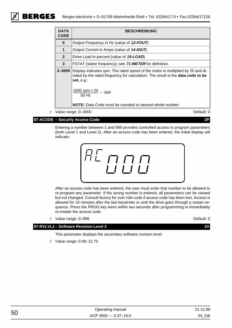
Berges electronic • D–51709 Marienheide-Rodt • Tel. 02264/17-0 • Fax 02264/17126
Operating manual 21.12.98
ACP 3000 — 0.37–15.0 04_GB50
◊ Value range: 0–3000 Default: 0
Entering a number between 1 and 999 provides controlled access to program parameters(both Level 1 and Level 2). After an access code has been entered, the initial display willindicate:
After an access code has been entered, the user must enter that number to be allowed tore-program any parameter. If the wrong number is entered, all parameters can be viewedbut not changed. Consult factory for over-ride code if access code has been lost. Access isallowed for 10 minutes after the last keystroke or until the drive goes through a restart se-quence. Press the PROG key twice within two seconds after programming to immediatelyre-instate the access code.
◊ Value range: 0–999 Default: 0
This parameter displays the secondary software revision level.
◊ Value range: 0.00–12.75
DATACODE
BESCHREIBUNG
0 Output Frequency in Hz (value of 12-FOUT).
1 Output Current in Amps (value of 14-IOUT).
2 Drive Load in percent (value of 15-LOAD).
3 FSTAT (stator frequency); see 71-METER for definition.
3–3000 Display indicates rpm. The rated speed of the motor is multiplied by 20 and di-vided by the rated frequency for calculation. The result is the data code to be set, e.g.:
NOTE: Data Code must be rounded to nearest whole number.
87-ACODE – Security Access Code 2P
97-RVLVL2 – Software Revision Level 2 2V
1500 rpm 20×50 Hz
-------------------------------------- 600=

21.12.98 Operating manual
04_GB ACP 3000 — 0.37–15.0 51
Berges electronic • D–51709 Marienheide-Rodt • Tel. 02264/17-0 • Fax 02264/17126
6 PI Controller
6.1 Introduction
ACP 3000 inverters have a built-in PI (Proportional-Integral) Controller that makes it possi-ble to control a process by adjusting motor speed using a reference input and a feedbackinput. When PI control is enabled, several new parameters (as well as new data codes forsome existing parameters) become available to support PI control.
This section first provides an overview of how PI control operates. Following this discus-sion, the new parameters and data codes are described.
6.2 Overview of PI Control
Figure 6.1 on the next page provides a flowchart of PI control. The characteristics of PI con-trol are set with the 81-PRGNO parameter (see page 56). The data codes for parameter81-PRGNO allow you to select:
Direct- or Reverse-Acting Loop
• In a direct-acting loop, a positive error will cause an increase in output frequency. Con-versely, in a reverse-acting loop, a positive error will cause a decrease in output frequen-cy.
Slow or Fast Rate of Integration
• A slow rate of integration is usually selected for processes with long time constraints (forexample, thermal and fluid level controls). On the other hand, a fast integration rate isutilized for processes with short time constraints (such as mechanical systems and pres-sure loops).
Whether Feed-Forward is Active
• Feed-forward is useful in situations where the reference value has a direct relation to thefeedback signal, such as controlling motor speed in a closed loop. Note that feed-for-ward should be enabled when attempting to close a speed loop.
Whether the PI Controller is turned on and off via the PS3 input.
Separate parameters are also available for adjusting proportional gain (parameter B3-KP),integral gain (parameter B4-KI), and scaling for the feedback terminal VIN1 (parameter B5-KIN). These parameters may be adjusted while the inverter is operating.

Berges electronic • D–51709 Marienheide-Rodt • Tel. 02264/17-0 • Fax 02264/17126
Operating manual 21.12.98
ACP 3000 — 0.37–15.0 04_GB52
Figure 6.1PI Controller Functional Diagram

21.12.98 Operating manual
04_GB ACP 3000 — 0.37–15.0 53
Berges electronic • D–51709 Marienheide-Rodt • Tel. 02264/17-0 • Fax 02264/17126
The PI Controller operates within the limits set by parameter A1-FCORR, the value of whichestablishes the frequency band across which the value of the integrator and the output ofthe PI Controller may vary. If Feed-Forward is active, the output of the PI Controller is thereference frequency 12-FOUT ± A1-FCORR, and the integrator's value is ± A1-FCORR.Note that the final output of the PI Controller cannot be less than 0.00 Hz nor greater than400.00 Hz.
The output of the PI Controller is sent to the ASIC after the proper frequency conversion.The controller works in one direction of rotation which must be set by FWD and REV com-mands. A change in direction while the controller is active yields unpredictable results.
The PI controller is limited in its application by the minimum resolution available through thefeedback terminal. Since the feedback terminal voltage is scaled through an 8-bit analog-to-digital converter, the reaction of the PI loop is reduced.
For example, if the inverter is set to run from 0.00 to 60.00 Hz and the feedback is comingfrom a tachometer rated at 50 V/1000 rpm and conditioned to be between 0–10 V with 2000RPM being full scale, then the minimum change that the 8-bit A/D converter can register is8 rpm. This means that, worst case, the speed can drop by 8 rpm when a load is applied,but typical accuracy is ±2%.
Input CTS or a STOP command (or inputs FWD and REV active at the same time) stopsthe inverter and resets the integrator part (sIPart) of the PI Controller when the value of 12-FOUT falls below 0.10 Hz.
6.3 Reference and Feedback Inputs
A. Configuration of Inputs
The PI reference value is input from either the keypad or the VIN2 terminal. The PI feedbackvalue is input from the VIN1 terminal. An error signal is calculated by the microprocessorwhich adjusts the speed of the inverter within a range limited by the A1-FCORR parameter.
The PI feedback input (VIN1) is selectable through J20 as 0 to5 VDC, 0-10 VDC, 0 to 20mA, or 4 to 20 mA. The PI reference input (VIN2) is selectable through J20 as 0 to 5 VDCor 0 to 10 VDC.
Parameter 24-FSEL is used to set the feedback input to be direct, inverted, or a 20% offsetfrom the minimum. This parameter must also be set to 16, 17, 18, or 19 to use VIN2 as thereference input. Enabling the PI Controller without properly setting 24-FSEL could result inthe use of a combination of VIN1 and VIN2 as the reference signal which will give unpre-dictable results.
B. Scaling the Feedback Input
The feedback input (VIN1) is scaled between 0.00 Hz and 1.125 times FMAX. For example,if VIN1 is set to “direct” and FMAX is 60.00 Hz, then a full scale feedback signal will corre-spond to 67.50 Hz.
This feedback input can also be scaled, via B5-KIN, from 0 to 255 which corresponds to arange of 0 to 1.99. For example, if B5-KIN = 64, then a full scale feedback signal would cor-respond to 33.75 Hz.
The function of scaling is to compensate the input for conditioning difficulties of the feed-back signal. For instance, if the feedback is from an analog tachometer that gives a 50 V /1000 rpm signal and the inverter is set up to have an FMAX of 60.0 Hz (which means thatVIN1 needs to read a signal of 67.5 Hz), then the maximum voltage from the tachometerwill be 101.25 V.

Berges electronic • D–51709 Marienheide-Rodt • Tel. 02264/17-0 • Fax 02264/17126
Operating manual 21.12.98
ACP 3000 — 0.37–15.0 04_GB54
This means that a voltage divider scaled to 0.0987 must be used if a maximum input voltageof 10 V is desired. Since voltage dividers are rarely exact, parameter B5-KIN can be usedto compensate. In this case, the divider gain was actually 0.100. This means that the inputwill be off scale by a factor of 1.01 which can be compensated by scaling to 0.987 or B5-KIN set to 126. See page 54 for an equation for calculating B5-KIN.
NOTE: Setting B5-KIN less than 128 or a scale less than 1 will limit the maximum speedthat the feedback terminal can read and therefore could cause unpredictable results. Seepage 54 for an equation for calculating the maximum feedback terminal.
6.4 Calculating PI Controller Values
The integral part of the PI controller output is calculated as follows:
N = 1 for fast integrator, 64 for slow integrator.e = Fout-Feedback (error signal calculated by PI Controller).kP, kI, kIN = 0–255.
Actual output speed of PI controller is calculated as follows:
To calculate maximum feedback:
To calculate actual feedback:
FIN is % of full scale voltage or current.
To calculate B5-KIN (calculated voltage scaling ratio of feedback signal):
PV = Process Parameter in Volts/RPM.VMAX = Maximum input Voltage (5 V or 10 V).ADIVA = Actual Voltage Divider Ratio.
6.5 Parameters for PI Control
A. Additional Parameters for PI Control
The following parameters become available when PI control is enabled; they are not avail-able when PI control is not utilized.
sIPart: sIPart kI e×8192 N×-----------------------+=
Actual Output Speed sIPart kP e×128
-----------------+=
Maximum Feedback kIN128---------- 9 FMAX×
8---------------------------×=
Actual Feedback Fin kIN128----------× 9 FMAX×
8---------------------------×=
ADIVVMAX
33.75 FMAX× PV×[ ]---------------------------------------------------------=
KIN 128ADIV
VDIVA----------------×=
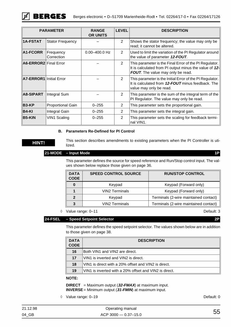
21.12.98 Operating manual
04_GB ACP 3000 — 0.37–15.0 55
Berges electronic • D–51709 Marienheide-Rodt • Tel. 02264/17-0 • Fax 02264/17126
B. Parameters Re-Defined for PI Control
This section describes amendments to existing parameters when the PI Controller is uti-lized.
This parameter defines the source for speed reference and Run/Stop control input. The val-ues shown below replace those given on page 36.
◊ Value range: 0–11 Default: 3
This parameter defines the speed setpoint selector. The values shown below are in additionto those given on page 38.
NOTE:
DIRECT = Maximum output (32-FMAX) at maximum input.INVERSE = Minimum output (31-FMIN) at maximum input.
◊ Value range: 0–19 Default: 0
PARAMETER RANGEOR UNITS
LEVEL DESCRIPTION
1A-FSTAT Stator Frequency – 2 Shows the stator frequency; the value may only be read; it cannot be altered.
A1-FCORR FrequencyCorrection
0.00–400.0 Hz 2 Used to limit the variation of the PI Regulator around the value of parameter 12-FOUT.
A6-ERROR2 Final Error – 2 This parameter is the Final Error of the PI Regulator. It is calculated from PI output minus the value of 12-FOUT. The value may only be read.
A7-ERROR1 Initial Error – 2 This parameter is the Initial Error of the PI Regulator. It is calculated from 12-FOUT minus feedback. The value may only be read.
A8-SIPART Integral Sum – 2 This parameter is the sum of the integral term of the PI Regulator. The value may only be read.
B3-KP Proportional Gain 0–255 2 This parameter sets the proportional gain.
B4-KI Integral Gain 0–255 2 This parameter sets the integral gain.
B5-KIN VIN1 Scaling 0–255 2 This parameter sets the scaling for feedback termi-nal VIN1.
21-MODE – Input Mode 1P
DATACODE
SPEED CONTROL SOURCE RUN/STOP CONTROL
0 Keypad Keypad (Forward only)
1 VIN2 Terminals Keypad (Forward only)
2 Keypad Terminals (2-wire maintained contact)
3 VIN2 Terminals Terminals (2-wire maintained contact)
24-FSEL – Speed Setpoint Selector 2P
DATACODE
DESCRIPTION
16 Both VIN1 and VIN2 are direct.
17 VIN1 is inverted and VIN2 is direct.
18 VIN1 is direct with a 20% offset and VIN2 is direct.
19 VIN1 is inverted with a 20% offset and VIN2 is direct.
HINT!
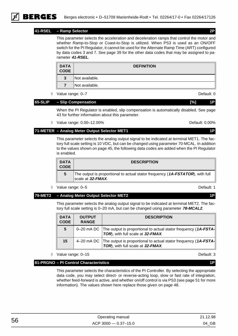
Berges electronic • D–51709 Marienheide-Rodt • Tel. 02264/17-0 • Fax 02264/17126
Operating manual 21.12.98
ACP 3000 — 0.37–15.0 04_GB56
This parameter selects the acceleration and deceleration ramps that control the motor andwhether Ramp-to-Stop or Coast-to-Stop is utilized. When PS3 is used as an ON/OFFswitch for the PI Regulator, it cannot be used for the Alternate Ramp Time (ART) configuredby data codes 3 and 7. See page 39 for the other data codes that may be assigned to pa-rameter 41-RSEL.
◊ Value range: 0–7 Default: 0
When the PI Regulator is enabled, slip compensation is automatically disabled. See page43 for further information about this parameter.
◊ Value range: 0.00–12.00% Default: 0.00%
This parameter selects the analog output signal to be indicated at terminal MET1. The fac-tory full scale setting is 10 VDC, but can be changed using parameter 70-MCAL. In additionto the values shown on page 45, the following data codes are added when the PI Regulatoris enabled.
◊ Value range: 0–5 Default: 1
This parameter selects the analog output signal to be indicated at terminal MET2. The fac-tory full scale setting is 0–20 mA, but can be changed using parameter 78-MCAL2.
◊ Value range: 0–15 Default: 3
This parameter selects the characteristics of the PI Controller. By selecting the appropriatedata code, you may select direct- or reverse-acting loop, slow or fast rate of integration,whether feed-forward is active, and whether on/off control is via PS3 (see page 51 for moreinformation). The values shown here replace those given on page 48.
41-RSEL – Ramp Selector 2P
DATACODE
DEFINITION
3 Not available.
7 Not available.
65-SLIP – Slip Compensation [%] 1P
71-METER – Analog Meter Output Selector MET1 1P
DATACODE
DESCRIPTION
5 The output is proportional to actual stator frequency (1A-FSTATOR), with full scale at 32-FMAX.
79-MET2 – Analog Meter Output Selector MET2 1P
DATACODE
OUTPUTRANGE
DESCRIPTION
5 0–20 mA DC The output is proportional to actual stator frequency (1A-FSTA-TOR), with full scale at 32-FMAX.
15 4–20 mA DC The output is proportional to actual stator frequency (1A-FSTA-TOR), with full scale at 32-FMAX.
81-PRGNO – PI Control Characteristics 1P

21.12.98 Operating manual
04_GB ACP 3000 — 0.37–15.0 57
Berges electronic • D–51709 Marienheide-Rodt • Tel. 02264/17-0 • Fax 02264/17126
◊ Value range: 0–9999 Default: 0
DATENCODE TYPE OF LOOP
INTEGRATION RATE
FEED-FORWARD
PI ENABLEDBY PS3?
80 Direct Slow Active No
81 Direct Fast Active No
82 Reverse Slow Active No
83 Reverse Fast Active No
84 Direct Slow Active Yes
85 Direct Fast Active Yes
86 Reverse Slow Active Yes
87 Reverse Fast Active Yes
88 Direct Slow Inactive No
89 Direct Fast Inactive No
90 Reverse Slow Inactive No
91 Reverse Fast Inactive No
92 Direct Slow Inactive Yes
93 Direct Fast Inactive Yes
94 Reverse Slow Inactive Yes
95 Reverse Fast Inactive Yes
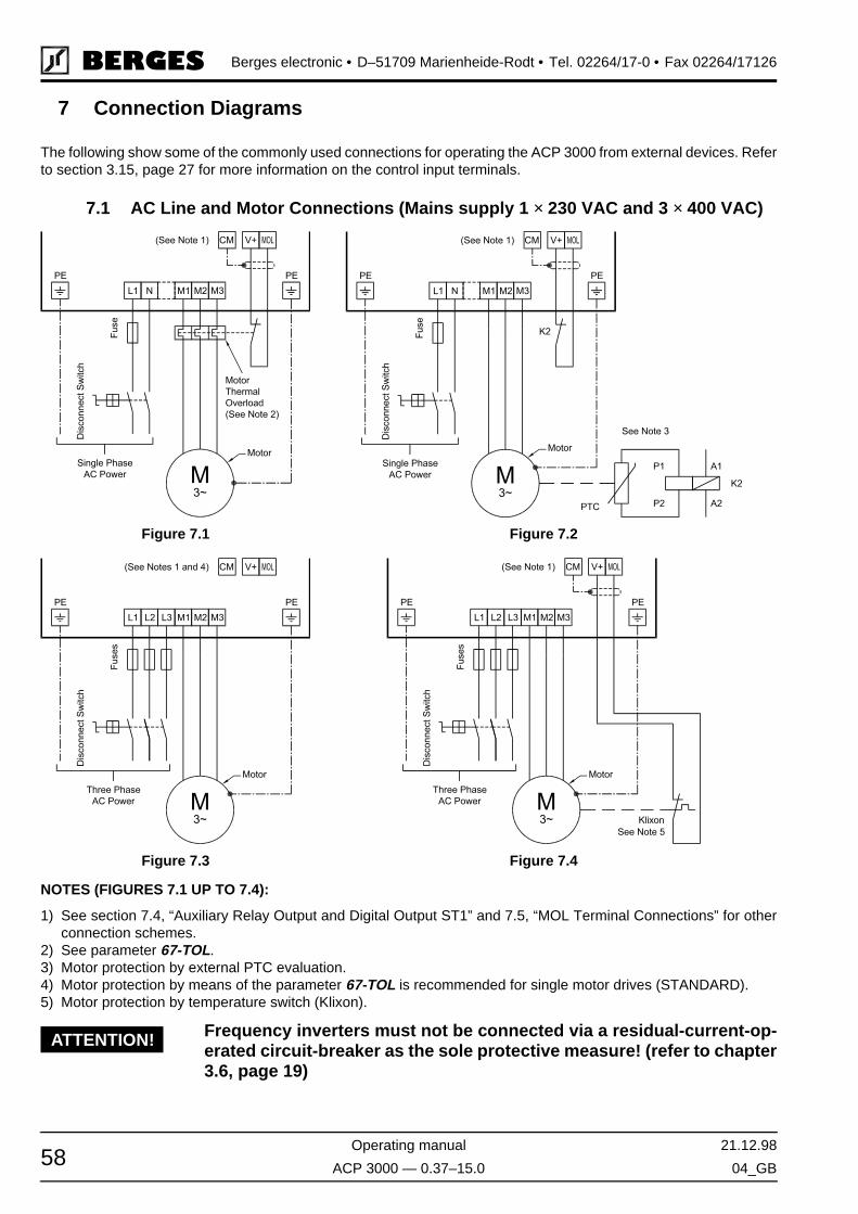
Berges electronic • D–51709 Marienheide-Rodt • Tel. 02264/17-0 • Fax 02264/17126
Operating manual 21.12.98
ACP 3000 — 0.37–15.0 04_GB58
7 Connection Diagrams
The following show some of the commonly used connections for operating the ACP 3000 from external devices. Referto section 3.15, page 27 for more information on the control input terminals.
7.1 AC Line and Motor Connections (Mains supply 1 × 230 VAC and 3 × 400 VAC)
NOTES (FIGURES 7.1 UP TO 7.4):
1) See section 7.4, “Auxiliary Relay Output and Digital Output ST1” and 7.5, “MOL Terminal Connections” for otherconnection schemes.
2) See parameter 67-TOL.3) Motor protection by external PTC evaluation.4) Motor protection by means of the parameter 67-TOL is recommended for single motor drives (STANDARD).5) Motor protection by temperature switch (Klixon).
Frequency inverters must not be connected via a residual-current-op-erated circuit-breaker as the sole protective measure! (refer to chapter3.6, page 19)
Figure 7.1 Figure 7.2
Figure 7.3 Figure 7.4
ATTENTION!

21.12.98 Operating manual
04_GB ACP 3000 — 0.37–15.0 59
Berges electronic • D–51709 Marienheide-Rodt • Tel. 02264/17-0 • Fax 02264/17126
7.2 2-Wire Run/Stop Connections
7.3 3-Wire Run/Stop Connections
7.4 Auxiliary Relay Output and Digital Output ST1
Figure 7.5
Figure 7.6
Figure 7.7 Figure 7.8
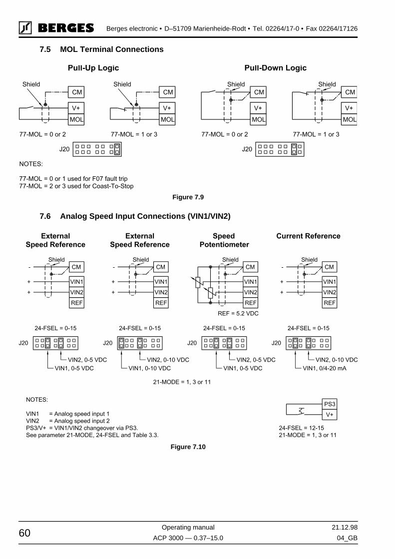
Berges electronic • D–51709 Marienheide-Rodt • Tel. 02264/17-0 • Fax 02264/17126
Operating manual 21.12.98
ACP 3000 — 0.37–15.0 04_GB60
7.5 MOL Terminal Connections
7.6 Analog Speed Input Connections (VIN1/VIN2)
Figure 7.9
Figure 7.10
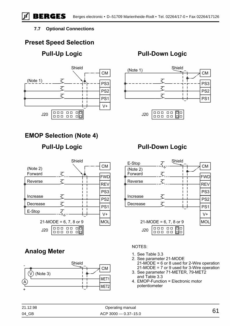
21.12.98 Operating manual
04_GB ACP 3000 — 0.37–15.0 61
Berges electronic • D–51709 Marienheide-Rodt • Tel. 02264/17-0 • Fax 02264/17126
7.7 Optional Connections
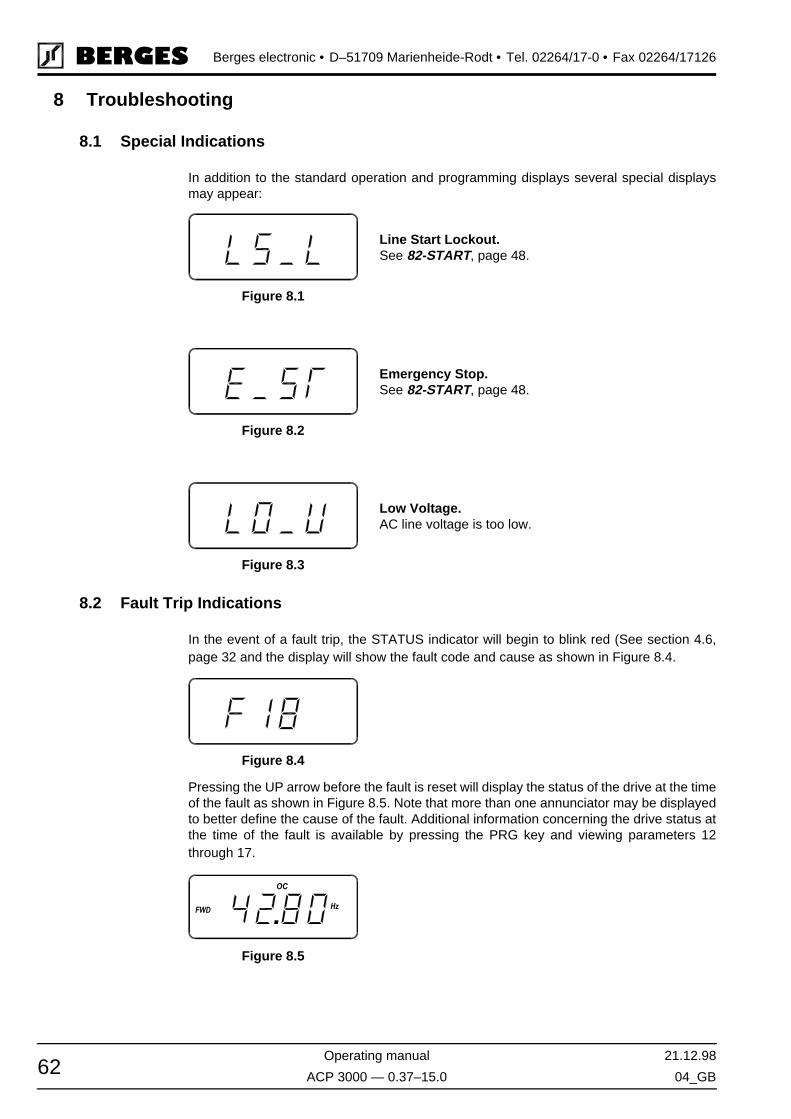
Berges electronic • D–51709 Marienheide-Rodt • Tel. 02264/17-0 • Fax 02264/17126
Operating manual 21.12.98
ACP 3000 — 0.37–15.0 04_GB62
8 Troubleshooting
8.1 Special Indications
In addition to the standard operation and programming displays several special displaysmay appear:
8.2 Fault Trip Indications
In the event of a fault trip, the STATUS indicator will begin to blink red (See section 4.6,page 32 and the display will show the fault code and cause as shown in Figure 8.4.
Pressing the UP arrow before the fault is reset will display the status of the drive at the timeof the fault as shown in Figure 8.5. Note that more than one annunciator may be displayedto better define the cause of the fault. Additional information concerning the drive status atthe time of the fault is available by pressing the PRG key and viewing parameters 12through 17.
Line Start Lockout.See 82-START, page 48.
Figure 8.1
Emergency Stop.See 82-START, page 48.
Figure 8.2
Low Voltage.AC line voltage is too low.
Figure 8.3
Figure 8.4
Figure 8.5
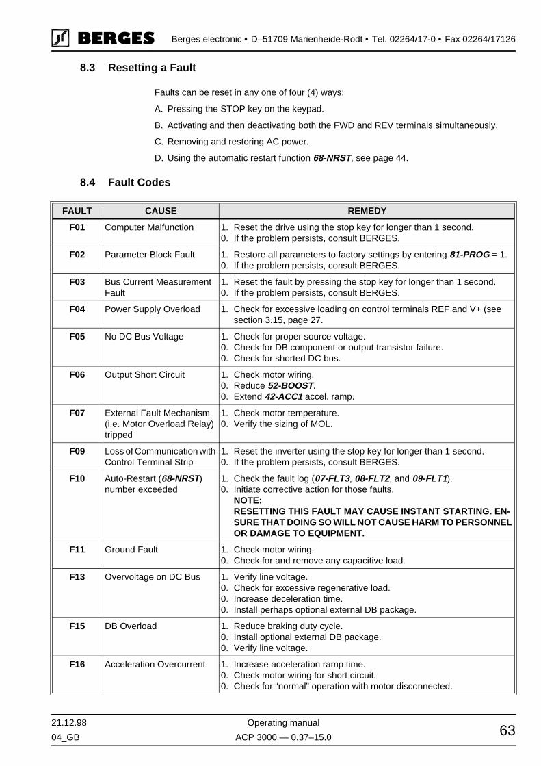
21.12.98 Operating manual
04_GB ACP 3000 — 0.37–15.0 63
Berges electronic • D–51709 Marienheide-Rodt • Tel. 02264/17-0 • Fax 02264/17126
8.3 Resetting a Fault
Faults can be reset in any one of four (4) ways:
A. Pressing the STOP key on the keypad.
B. Activating and then deactivating both the FWD and REV terminals simultaneously.
C. Removing and restoring AC power.
D. Using the automatic restart function 68-NRST, see page 44.
8.4 Fault Codes
FAULT CAUSE REMEDY
F01 Computer Malfunction 1. Reset the drive using the stop key for longer than 1 second.0. If the problem persists, consult BERGES.
F02 Parameter Block Fault 1. Restore all parameters to factory settings by entering 81-PROG = 1.0. If the problem persists, consult BERGES.
F03 Bus Current Measurement Fault
1. Reset the fault by pressing the stop key for longer than 1 second.0. If the problem persists, consult BERGES.
F04 Power Supply Overload 1. Check for excessive loading on control terminals REF and V+ (see section 3.15, page 27.
F05 No DC Bus Voltage 1. Check for proper source voltage.0. Check for DB component or output transistor failure.0. Check for shorted DC bus.
F06 Output Short Circuit 1. Check motor wiring.0. Reduce 52-BOOST.0. Extend 42-ACC1 accel. ramp.
F07 External Fault Mechanism (i.e. Motor Overload Relay) tripped
1. Check motor temperature.0. Verify the sizing of MOL.
F09 Loss of Communication with Control Terminal Strip
1. Reset the inverter using the stop key for longer than 1 second.0. If the problem persists, consult BERGES.
F10 Auto-Restart (68-NRST) number exceeded
1. Check the fault log (07-FLT3, 08-FLT2, and 09-FLT1).0. Initiate corrective action for those faults.
NOTE:RESETTING THIS FAULT MAY CAUSE INSTANT STARTING. EN-SURE THAT DOING SO WILL NOT CAUSE HARM TO PERSONNEL OR DAMAGE TO EQUIPMENT.
F11 Ground Fault 1. Check motor wiring.0. Check for and remove any capacitive load.
F13 Overvoltage on DC Bus 1. Verify line voltage.0. Check for excessive regenerative load.0. Increase deceleration time.0. Install perhaps optional external DB package.
F15 DB Overload 1. Reduce braking duty cycle.0. Install optional external DB package.0. Verify line voltage.
F16 Acceleration Overcurrent 1. Increase acceleration ramp time.0. Check motor wiring for short circuit.0. Check for “normal” operation with motor disconnected.

Berges electronic • D–51709 Marienheide-Rodt • Tel. 02264/17-0 • Fax 02264/17126
Operating manual 21.12.98
ACP 3000 — 0.37–15.0 04_GB64
NOTES:
1. Faults F01–F11 are checked during the power-up sequence.F02 is also checked during programming.
2. Faults F11-F20 will be reset and the inverter restarted if the Auto-Restart function is se-lected (see 68-NRST).
F17 Deceleration Overcurrent 1. Increase deceleration ramp time.0. Install perhaps optional external DB package.
F18 Running Overcurrent 1. Locate cause of mechanical overload on the motor.
F19 Heat sink Over Tempera-ture
1. Check for excessive overload.0. Verify the proper sizing of the drive for the application.0. Locate the drive in a cooler location, out of direct sunlight.
F20 Timed Overload 1. Check programming of 67-TOL.0. Check for overload on the motor.
PROBLEM CHECK POINT CORRECTIVE ACTION
Motor is not run-ning
Incorrect wiring 1. Check all power and control wiring.
External frequency command (if used)
1. Verify that the external frequency control signal is properly connected.0. Verify the integrity of the frequency control potentiometer (if used).
Programming selec-tions
1. Verify that the proper programming selections have been made for the application.
Fault 1. Verify that the inverter has not shutdown due to a fault condition.0. Consult section 8.4, page 63.
Motor stall 1. Release any overload on the motor.0. Verify that adequate torque boost is available.
Motor speed fluctuation
Loose terminal con-nection
1. Stop the inverter, turn off power, and tighten all terminal screws.0. Check for tightness of all connections within the drive.
Frequency control potentiometer erratic
1. Replace frequency control potentiometer.
Motor speed too high or too low
Frequency profile 1. Verify that the setting of 31-FMIN, 32-FMAX, and 53-FKNEE are cor-rect for the motor specification and application.
Frequency control signal
1. Verify the input signal level.
Motor nameplate specifications
1. Verify that the motor selection is proper for the application.
FAULT CAUSE REMEDY
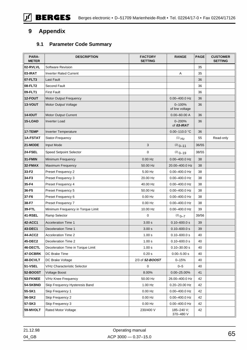
21.12.98 Operating manual
04_GB ACP 3000 — 0.37–15.0 65
Berges electronic • D–51709 Marienheide-Rodt • Tel. 02264/17-0 • Fax 02264/17126
9 Appendix
9.1 Parameter Code Summary
PARA-METER
DESCRIPTION FACTORYSETTING
RANGE PAGE CUSTOMERSETTING
02-RVLVL Software Revision 35
03-IRAT Inverter Rated Current A 35
07-FLT3 Last Fault 36
08-FLT2 Second Fault 36
09-FLT1 First Fault 36
12-FOUT Motor Output Frequency 0.00–400.0 Hz 36
13-VOUT Motor Output Voltage 0–100%of line voltage
36
14-IOUT Motor Output Current 0.00–60.00 A 36
15-LOAD Inverter Load 0–200%of 03-IRAT
36
17-TEMP Inverter Temperature 0.00–110.0 °C 36
1A-FSTAT Stator-Frequency (1) Hz 55 Read-only
21-MODE Input Mode 3 (2) 0–11 36/55
24-FSEL Speed Setpoint Selector 0 (2) 0–19 38/55
31-FMIN Minimum Frequency 0.00 Hz 0.00–400.0 Hz 38
32-FMAX Maximum Frequency 50.00 Hz 20.00–400.0 Hz 38
33-F2 Preset Frequency 2 5.00 Hz 0.00–400.0 Hz 38
34-F3 Preset Frequency 3 20.00 Hz 0.00–400.0 Hz 38
35-F4 Preset Frequency 4 40.00 Hz 0.00–400.0 Hz 38
36-F5 Preset Frequency 5 50.00 Hz 0.00–400.0 Hz 38
37-F6 Preset Frequency 6 0.00 Hz 0.00–400.0 Hz 38
38-F7 Preset Frequency 7 0.00 Hz 0.00–400.0 Hz 38
39-FTL Minimum Frequency in Torque Limit 10.00 Hz 0.00–400.0 Hz 39
41-RSEL Ramp Selector 0 (2) 0–7 39/56
42-ACC1 Acceleration Time 1 3.00 s 0.10–600.0 s 39
43-DEC1 Deceleration Time 1 3.00 s 0.10–600.0 s 39
44-ACC2 Acceleration Time 2 1.00 s 0.10–600.0 s 40
45-DEC2 Deceleration Time 2 1.00 s 0.10–600.0 s 40
46-DECTL Deceleration Time in Torque Limit 1.00 s 0.10–30.00 s 40
47-DCBRK DC Brake Time 0.20 s 0.00–5.00 s 40
48-DCVLT DC Brake Voltage 2/3 of 52-BOOST 0–15% 40
51-VSEL V/Hz Characteristic Selector 0 0–5 40
52-BOOST Voltage Boost 8.00% 0.00–25.00% 41
53-FKNEE V/Hz Knee Frequency 50.00 Hz 26.00–400.0 Hz 42
54-SKBND Skip Frequency Hysteresis Band 1.00 Hz 0.20–20.00 Hz 42
55-SK1 Skip Frequency 1 0.00 Hz 0.00–400.0 Hz 42
56-SK2 Skip Frequency 2 0.00 Hz 0.00–400.0 Hz 42
57-SK3 Skip Frequency 3 0.00 Hz 0.00–400.0 Hz 42
59-MVOLT Rated Motor Voltage 230/400 V 185–240 V;370–480 V
42
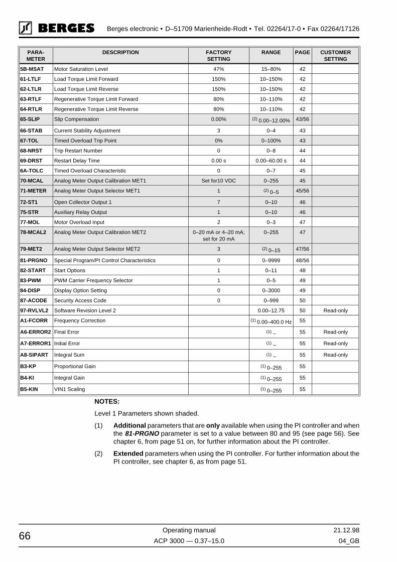
Berges electronic • D–51709 Marienheide-Rodt • Tel. 02264/17-0 • Fax 02264/17126
Operating manual 21.12.98
ACP 3000 — 0.37–15.0 04_GB66
NOTES:
Level 1 Parameters shown shaded.
(1) Additional parameters that are only available when using the PI controller and whenthe 81-PRGNO parameter is set to a value between 80 and 95 (see page 56). Seechapter 6, from page 51 on, for further information about the PI controller.
(2) Extended parameters when using the PI controller. For further information about thePI controller, see chapter 6, as from page 51.
5B-MSAT Motor Saturation Level 47% 15–80% 42
61-LTLF Load Torque Limit Forward 150% 10–150% 42
62-LTLR Load Torque Limit Reverse 150% 10–150% 42
63-RTLF Regenerative Torque Limit Forward 80% 10–110% 42
64-RTLR Regenerative Torque Limit Reverse 80% 10–110% 42
65-SLIP Slip Compensation 0.00% (2) 0.00–12.00% 43/56
66-STAB Current Stability Adjustment 3 0–4 43
67-TOL Timed Overload Trip Point 0% 0–100% 43
68-NRST Trip Restart Number 0 0–8 44
69-DRST Restart Delay Time 0.00 s 0.00–60.00 s 44
6A-TOLC Timed Overload Characteristic 0 0–7 45
70-MCAL Analog Meter Output Calibration MET1 Set for10 VDC 0–255 45
71-METER Analog Meter Output Selector MET1 1 (2) 0–5 45/56
72-ST1 Open Collector Output 1 7 0–10 46
75-STR Auxiliary Relay Output 1 0–10 46
77-MOL Motor Overload Input 2 0–3 47
78-MCAL2 Analog Meter Output Calibration MET2 0–20 mA or 4–20 mA;set for 20 mA
0–255 47
79-MET2 Analog Meter Output Selector MET2 3 (2) 0–15 47/56
81-PRGNO Special Program/PI Control Characteristics 0 0–9999 48/56
82-START Start Options 1 0–11 48
83-PWM PWM Carrier Frequency Selector 1 0–5 49
84-DISP Display Option Setting 0 0–3000 49
87-ACODE Security Access Code 0 0–999 50
97-RVLVL2 Software Revision Level 2 0.00–12.75 50 Read-only
A1-FCORR Frequency Correction (1) 0.00–400.0 Hz 55
A6-ERROR2 Final Error (1) – 55 Read-only
A7-ERROR1 Initial Error (1) – 55 Read-only
A8-SIPART Integral Sum (1) – 55 Read-only
B3-KP Proportional Gain (1) 0–255 55
B4-KI Integral Gain (1) 0–255 55
B5-KIN VIN1 Scaling (1) 0–255 55
PARA-METER
DESCRIPTION FACTORYSETTING
RANGE PAGE CUSTOMERSETTING

21.12.98 Operating manual
04_GB ACP 3000 — 0.37–15.0 67
Berges electronic • D–51709 Marienheide-Rodt • Tel. 02264/17-0 • Fax 02264/17126
9.2 Parameters Added or Amended when PI Control is Utilized
The following table lists the parameters that become available when PI control is enabledby setting parameter 81-PRGNO to a value between 80 and 95 (see page 56). It also liststhose parameters where data codes change due to the enabling of P1 control. For furtherinformation on PI control, see section 6 starting on page 51.
9.3 Options
A. XRK01 – Remote Keypad Unit
The XRK01 – Remote Keypad Unit (RKU) is a portable, hand held accessory. When con-nected to an ACP 3000-inverter, it will function in parallel with an existing keypad or allowa chassis model to be controlled and programmed. The RKU is powered by a 9 V alkalinebattery (supplied) or an optional AC adapter (PA24DC). Auto Power Down and backlightcontrol features conserve battery life by automatically turning the RKU off after a specifiedtime period and allowing selected use of the display backlight.
PARAMETER LEVEL RANGE (DEFAULT) USER SETTING SEE PAGE
Parameters That Are Added When PI Control Is Enabled:
1A-FSTAT Stator Frequency 2 – Read-only 55
A1-FCORR Frequency Correction 2 0.00–400.0 Hz 55
A6-ERROR2 Final Error 2 – Read-only 55
A7-ERROR1 Initial Error 2 – Read-only 55
A8-SIPART Integral Sum 2 – Read-only 55
B3-KP Proportional Gain 2 0–255 55
B4-KI Integral Gain 2 0–255 55
B5-KIN VIN1 Scaling 2 0–255 55
Parameters That Are Amended When PI Control Is Enabled:
21-MODE Input Mode 1 If PS3 is used for on/off control, preset speed switch and jog/run are not available.
55
24-FSEL Speed Setpoint Selector 2 Four data codes area added; range is now 0–3 and 16–19.
55
41-RSEL Ramp Selector 2 If PS3 is used for on/off control, Alternate Ramp Time (ART) is not available. Range is now 0–2 and 4–6 (data codes 3 & 7 are disabled).
56
65-SLIP Slip Compensation 1 This parameter is disabled. 56
71-METER Analog Meter Output Selector MET1
1 Data codes 5 is added; the range is now 0–5. 56
79-MET2 Analog Meter Output Selector MET2
1 Two data codes are added; the range is now 0–5 and 11–15.
56
81-PRGNO Special Program 2 Data codes 80–95 added to select type of PI con-trol desired.
56

Berges electronic • D–51709 Marienheide-Rodt • Tel. 02264/17-0 • Fax 02264/17126
Operating manual 21.12.98
ACP 3000 — 0.37–15.0 04_GB68
B. XPM01 – Program Memory Unit
The XPM01 – Program Memory Unit (PMU) is another portable, handheld accessory. Whenconnected to an ACP 3000-inverter with software revision 13.1 or greater, it allows opera-tion and programming like the RKU. In addition, it allows up to ten different parameter setsto be stored internally. Any one can be downloaded to the inverter's active memory or cus-tomer parameter set. Uploading parameter sets from an inverter to a PMU memory locationis also possible. The PMU is powered by a 9 V alkaline battery or the AC adapter (both sup-plied). Auto Power Down and backlight control features conserve battery life by automati-cally turning the PMU off after a specified time period and allowing selected use of thedisplay backlight.
C. XRP01 – Remote Panel Keypad
The XRP01 Remote Panel Keypad is a IP 54 rated, panel mountable accessory. Whenproperly installed, the XRP01 seals into the host enclosure, assuring that the IP 54 integrityis preserved. When connected to an ACP 3000 Series inverter, it will function in parallel withthe existing keypad to allow the inverter to be controlled and programmed. The XRP01 isself powered and can be powered by an optional external AC adapter (PA24DC) or a cus-tomer supplied +24 VDC source.
D. XRP02 – Remote Panel Programmer
The XRP02 Remote Panel Programmer is a IP 54 rated, panel-mountable accessory.When properly installed, the XRP02 seals into the host enclosure, assuring that the IP 54integrity is preserved. When connected to an ACP 3000 Series inverter with software revi-sion 13.1 or greater, it allows operation and programming like the XRP01. In addition, it al-lows up to ten different parameter sets to be stored internally. Any one can be downloadedto the inverter's active memory or customer parameter set. Uploading parameter sets froman inverter to an on board memory location is also possible. The XRP02 is self poweredand can be powered by an optional external AC adapter (PA24DC) or a customer supplied+24 VDC source.

21.12.98 Operating manual
04_GB ACP 3000 — 0.37–15.0
Berges electronic • D–51709 Marienheide-Rodt • Tel. 02264/17-0 • Fax 02264/17126

Berges electronic • D–51709 Marienheide-Rodt • Tel. 02264/17-0 • Fax 02264/17126
Operating manual 21.12.98
ACP 3000 — 0.37–15.0 04_GB


BERGES electronic GmbHIndustriestraße 13 • D–51709 Marienheide-RodtPostfach 1140 • D–51703 MarienheideTel. (0 22 64) 17-0 • Fax (0 22 64) 1 71 26http://www.berges.de • e-mail: [email protected]