04 rliu quantitative measurement molten steel surface...
TRANSCRIPT
CCC Annual Report 2010UIUC, August 12, 2010
Quantitative Measurement of Molten Steel
Surface Velocity with Nail Boards and SVC
Sensor in CC Molds
R. Liu *, J. Sengupta **, D. Crosbie **, S. Chung ***, M. Trinh *** and B. Thomas *
*Department of Mechanical Science & Engineering
University of Illinois at Urbana-Champaign
Sensor in CC Molds
**Global Research and Development***Steelmaking Technology
ArcelorMittal Dofasco Inc.
Objectives
• To examine the accuracy of measuring molten steel meniscus velocity using nail boards
• To evaluate and compare the following two methods i n measuring liquid steel surface velocity, – using Sub -meniscus Velocity Control (SVC) device
University of Illinois at Urbana-Champaign • Metals Processing Simulation Lab • Rui Liu 2
– using Sub -meniscus Velocity Control (SVC) device– using nail boards
• To validate the numerical models for the turbulent multiphase flow in the mold using nail board/SVC measurements

Background
• Meniscus velocity is critical to the quality of fin al products in continuous casting process
• Difficulty with measuring surface velocity is from:– liquid metal flow with very high temperature (1550 C or above)– direct visualization of the liquid steel flow patte rn is not
University of Illinois at Urbana-Champaign • Metals Processing Simulation Lab • Rui Liu 3
– direct visualization of the liquid steel flow patte rn is not available
• Methods to quantify surface velocities include:– Plant measurements using nail boards or other senso r devices– Mathematical and numerical modeling– Physical modeling and scaling
Introduction to Nail Board Measurement
Procedures:
1. Insert the nail into the surface of liquid steel flow through the slag layer
2. Liquid steel runs up on the nail frontal area, an d decreases on the other wake region of the nail, as it solidifies into a lump
University of Illinois at Urbana-Champaign • Metals Processing Simulation Lab • Rui Liu 4
Nail Board with 6 mm φφφφ Nail
3. The height difference between either side of the lump is measured and converted into surface velocity of liquid steel using the calibration curves [1]
nailsteel flowslag layer
dip the nail for 3~5 sec,then remove it from steel
solidifiedlump
nail
lump height difference
Ref:[1] B. Rietow and B. Thomas, Master’s Thesis

0.4
0.5
0.6
0.7
0.8
Vel
ocity
(m
/s)
Simulations by RietowCurve FitExtended Curve Fit
5 mm Lump φ 10 mm Lump φ
15 mm Lump φ
Lump Height Difference and Calibration Curves
hlump
University of Illinois at Urbana-Champaign • Metals Processing Simulation Lab • Rui Liu 5
-2 0 2 4 6 8 10 12 14 16 18 20
0.0
0.1
0.2
0.3
Vel
ocity
(m
/s)
Lump Height Difference (mm)
15 mm Lump φ
y = 0.1978*x0.59915 (R2 = 0.93)
y = 0.1256*x0.55759 (R2 = 0.97)
y = 0.0986*x0.55569 (R2 = 0.97)
dlump
6 mm φφφφ Nail and Lump
• The meniscus velocity vs. lump height difference cu rve is extended to predict high surface velocities.• The lump diameter is usually ranging from 10~15 mm for a 6-mm diameter nail.
: arc length from point H’ to point P’ on the nail circumference
H
PL
nail
lump
Flow Direction and Meniscus Velocity towards SEN/NF
H = High Point on LumpL = Low Point on LumpP = Reference Point(P always faces the operator)
1dParameters to measure:
: arc length from point L’ to point P’ on the nail circumference
2d
lumpd : lump diameter
H’ = High Point on NailL’ = Low Point on NailP’ = Reference Point on Nail
d
P’
H’L’
University of Illinois at Urbana-Champaign • Metals Processing Simulation Lab • Rui Liu 6
αβ
sV Nail
H
PL
122
lump nail
dPH
d dα = =
222
lump nail
dPL
d dβ = =
( ) 1 21 1
2 2 2 2avgnail
d d
d
π πγ α β α β − = − + − = − =
SEN naild : nail diameter
H’
P’L’
mVγ
1 2cosm snail
d dV
d
−=
V
VS : steel surface velocity
Vm : meniscus velocity towards SEN/NF

Error Estimation for Nail Board Measurements
( ) ( )1 2 1 21 2
15 10cos
5 5lump lumpb b
m lump lumpnail
d d d dV a h a h
d
− − −= +
Final form of meniscus velocity:
magnitude of surface velocity vector from linear interpolation of the calibration curves: sV
projection from flow direction to meniscus horizontal direction
In current measurement, lump diameter is between 10 mm and 15 mm, close to 10 mm. Parameters a1, b1, a2 and b2are constants from the curve fit:
Differentiating the equation above gives the error estimation:
University of Illinois at Urbana-Champaign • Metals Processing Simulation Lab • Rui Liu 7
( ) ( ) ( ) ( )1 21 2
m m mm lump lump
lump lump
V V VdV d d d h d d d
d h d d
∂ ∂ ∂= + + −∂ ∂ ∂ −
( )
( )
( ) ( )
2 1
1 2
1 2
2 1 1 2
1 1 1 21 1 2 2
1 21 2 1
cos5
15 10cos
5 5
15 10sin
5 5
b blump lump
m lumpnail
lump lumpb blump lump lump
nail
lump lumpb blump lump
nail
a h a h d ddV d d
d
d d d da b h a b h d h
d
d d d da h a h d d
d
− −
− −=
− − −+ +
− − −+ +
( )2d−
fit:
Model Geometry
Parameters
Value
a1 0.1256
b1 0.55759
a2 0.0986
b2 0.55569
0.5mm±
Casting Conditions for Trial #1
Description:1. Casting speed changes,2. SEN submergence
depth keeps constant3. Mold width keeps
constant4. Different SEN for strand
#1 and strand #2
University of Illinois at Urbana-Champaign • Metals Processing Simulation Lab • Rui Liu 8
SEN Submergence Depth: 177 mm
#1 and strand #2
Objective:To study the meniscus velocity change corresponding to the casting speed change.
Devices:1. SVC probe2. Nail board
Submergence depth for the SVC probe: 100 mm

SVC VS. Nail Board Measurement-- Trial #1, Strand #1
SVC VS. Nail Board
• Data Type—SVC: continuous dataNail Board:discrete data
University of Illinois at Urbana-Champaign • Metals Processing Simulation Lab • Rui Liu 9
1. Meniscus velocity magnitude increases as casting speed increases;2. Double-roll flow pattern increases as casting spe ed increases; 3. At low casting speed (1.0 m/min, between 40~60 mi n), complex flow pattern exists
Nail board data is nicely matching with the SVC data, both showing the same trend of meniscus velocity change with casting speed.
SVC VS. Nail Board Measurement-- Trial #1, Strand #2
SVC VS. Nail Board
• Data Type—SVC: continuous dataNail Board:discrete data
University of Illinois at Urbana-Champaign • Metals Processing Simulation Lab • Rui Liu 10
1. Complex flow pattern is observed through the whol e process;2. High casting speed tends to increase double-roll flow pattern, while low casting
speed tends to cause single-roll flow pattern.
Nail board data is nicely matching with the SVC data, capturing both the trend for velocity change and the turbulent transients
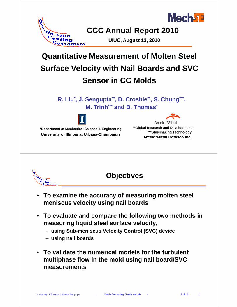
Casting Conditions for Trial #2-- Strand #2 with new SEN design
Description:1. Casting speed changes,2. SEN submergence also
changes3. Mold width keeps
constant
Objective:
University of Illinois at Urbana-Champaign • Metals Processing Simulation Lab • Rui Liu 11
Objective:To study the meniscus velocity change corresponding to the casting speed change for strand #2 with new SEN design.
Devices:1. SVC probe2. Nail board
Submergence depth for the SVC probe: 100 mm
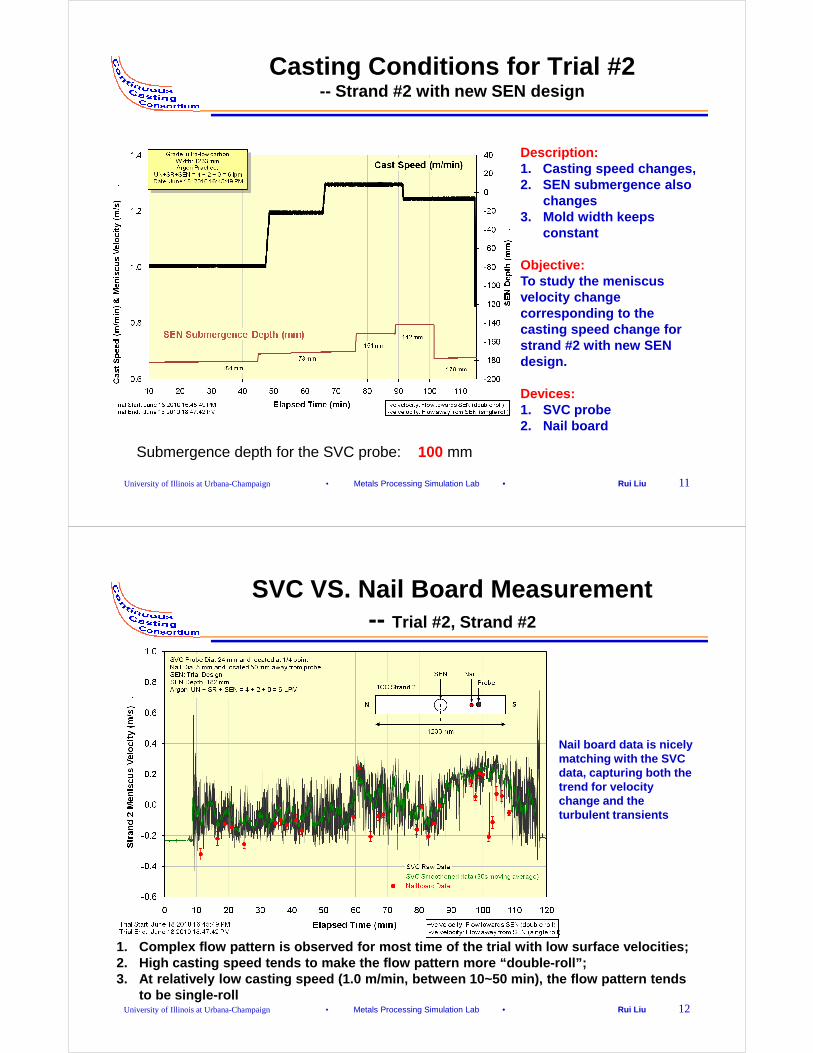
SVC VS. Nail Board Measurement-- Trial #2, Strand #2
Nail board data is nicely matching with the SVC data, capturing both the trend for velocity
University of Illinois at Urbana-Champaign • Metals Processing Simulation Lab • Rui Liu 12
1. Complex flow pattern is observed for most time of the trial with low surface velocities;2. High casting speed tends to make the flow pattern more “double-roll”; 3. At relatively low casting speed (1.0 m/min, betwe en 10~50 min), the flow pattern tends
to be single-roll
trend for velocity change and the turbulent transients
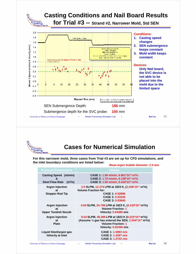
Casting Conditions and Nail Board Results for Trial #3 -- Strand #2, Narrower Mold, Std SEN
Conditions:1. Casting speed
changes2. SEN submergence
keeps constant3. Mold width keeps
constant
Devices:
University of Illinois at Urbana-Champaign • Metals Processing Simulation Lab • Rui Liu 13
SEN Submergence Depth: 186 mm
Devices:Only Nail board, the SVC device is not able to be placed into the mold due to the limited space
Submergence depth for the SVC probe: 100 mm
Cases for Numerical Simulation
Process Parameters Values
Casting Speed (m/min)&
Steel Flow Rate (m 3/s)
CASE 1: 1.90 m/min, 6.861*10 -3 m3/sCASE 2: 1.70 m/min, 6.138*10 -3 m3/sCASE 3: 1.50 m/min, 5.416*10 -3 m3/s
Argon Injection at
2.0 SLPM, 12.276 LPM at 1823 K, ( 2.046*10-4 m3/s) Volume Fraction for:
For this narrower mold, three cases from Trial #3 a re set up for CFD simulations, and the inlet boundary conditions are listed below:
Mean argon bubble diameter: 2.5 mm
University of Illinois at Urbana-Champaign • Metals Processing Simulation Lab • Rui Liu 14
at Stopper-Rod Tip
Volume Fraction for:CASE 1: 0.02896CASE 2: 0.03226CASE 3: 0.03640
Argon Injectionat
Upper Tundish Nozzle
4.04 SLPM, 24.798 LPM at 1823 K, ( 4.133*10-4 m3/s)Volume Fraction: 1
Velocity: 0.04385 m/s
Argon Injectionat
Plate
8.03 SLPM, 49.289 LPM at 1823 K ( 8.215*10-4 m3/s)(Assume ¼ gas has entered the SEN, 2.054*10-4 m3/s)
Volume Fraction: 1Velocity: 0.02456 m/s
Liquid Steel/argon gas Velocity at Inlet
CASE 1: 1.5993 m/sCASE 2: 1.4357 m/sCASE 3: 1.2722 m/s
X
Y
Z
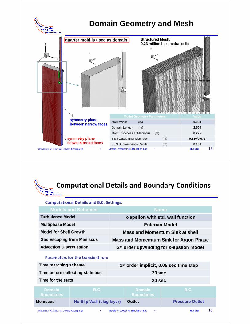
Domain Geometry and Mesh
X
Y
Z
Structured Mesh:0.23 million hexahedral cells
X
Y
Z
quarter mold is used as domain
University of Illinois at Urbana-Champaign • Metals Processing Simulation Lab • Rui Liu 15
Model Geometry Parameters Value
Mold Width (m) 0.983
Domain Length (m) 2.500
Mold Thickness at Meniscus (m) 0.225
SEN Outer/Inner Diameter (m) 0.130/0.075
SEN Submergence Depth (m) 0.186
symmetry plane between broad faces
symmetry plane between narrow faces
Computational Details and Boundary Conditions
Computational Details and B.C. Settings:
Models and Schemes Name
Turbulence Model k-epsilon with std. wall function
Multiphase Model Eulerian Model
Model for Shell Growth Mass and Momentum Sink at shell
Gas Escaping from Meniscus Mass and Momemtum Sink for Argon Phase
University of Illinois at Urbana-Champaign • Metals Processing Simulation Lab • Rui Liu 16
Advection Discretization 2st order upwinding for k-epsilon model
Domain Boundaries
B.C. Domain Boundaries
B.C.
Meniscus No-Slip Wall (slag layer) Outlet Pressure Outlet
Time marching scheme 1st order implicit, 0.05 sec time step
Time before collecting statistics 20 sec
Time for the stats 20 sec
Parameters for the transient run:

-0.8
-0.7
-0.6
-0.5
1.71.51.31.1
0.5m/s
Velocity Magnitude(m/s)
-0.8
-0.7
-0.6
-0.5
0.5 m/s
SEN SEN
Steel Velocity Distribution in the Mold
Casting speed:
1.5 m/min 1.7 m/min 1.9 m/min
Steel velocity distribution at center plane between broad faces
Recirculation zones below meniscus near SEN
SEN
old
Hei
ght
(m)
-0.8
-0.7
-0.6
-0.5
0.5 m/s
SEN
1.5 m/min
University of Illinois at Urbana-Champaign • Metals Processing Simulation Lab • Rui Liu 17
-0.5 -0.4 -0.3 -0.2 -0.1 0 0.1-1.1
-1
-0.9
1.10.90.70.50.30.1
-0.5 -0.4 -0.3 -0.2 -0.1 0-1.1
-1
-0.9
Increasing casting speed will:
1. reduce gas momentum along outer SEN
2. bend the liquid steel jet towards meniscus
3. increase liquid steel surface velocity (more doub le roll)
Vector plots show liquid steel mean velocity over
20 sec
double roll flow patterndouble roll flow patterncomplex flow patternMold WIdth (m)
Mo
-0.5 -0.4 -0.3 -0.2 -0.1 0-1.1
-1
-0.9
0.2
0.3
0.4
0.5
0.6
Men
iscu
s V
eloc
ity (
m/s
)
Comparison with Nail Board Data
SEN
• Reasons for not matching measurement at lower casting speeds:
-- RANS model tends to over-predict gas volume fraction at upper port exit region, thus generates higher drag force near outer SEN, which increases “single-roll” flow
University of Illinois at Urbana-Champaign • Metals Processing Simulation Lab • Rui Liu 18
-0.5 -0.4 -0.3 -0.2 -0.1 0.0
-0.6
-0.5
-0.4
-0.3
-0.2
-0.1
0.0
0.1
Men
iscu
s V
eloc
ity (
m/s
)
Mold Width (m)
vc = 1.5 m/min, simulation
vc = 1.7 m/min, simulation
vc = 1.9 m/min, simulation
vc = 1.5 m/min, NB
vc = 1.7 m/min, NB
vc = 1.9 m/min, NB
-- No-slip B.C. at top surface in CFD models is not quite appropriate
-- Thicker boundary layers at lower casting speeds
Velocity profiles are taken at 2 mm below top surface
Lines: Mean Horizontal V
Error Bars: RMS Mean V

Conclusions –1
• By matching the data with SVC results, nail board measurement is able to capture both the mean veloci ty trend and the turbulent transients for the surface flow of the liquid steel, thus it can be used to quantify t he meniscus steel velocity in CC molds, with the error estimated;
University of Illinois at Urbana-Champaign • Metals Processing Simulation Lab • Rui Liu 19
estimated;
• Observation from the measured data shows– meniscus velocity increases with casting speed;– complex flow pattern exists for cases with medium c asting
speeds (~1 m/min for 1200 mm mold width)– low casting speeds tend to generate single-roll flo w patterns,
while high casting speeds tend to generate double-r oll flow patterns in the mold (due to argon injection)
• Compare the two methods to measure surface steel velocity:– SVC:
– generates continuous meniscus velocity data, showin g the details of the flow
– expensive device to use– measures the steel velocities at some distance bene ath
Conclusions –2
University of Illinois at Urbana-Champaign • Metals Processing Simulation Lab • Rui Liu 20
– measures the steel velocities at some distance bene ath meniscus
– usually velocity at only one point on the surface c an be obtained
– Nail board:– gives limited discrete data points, recording insta ntaneous
meniscus velocities– cheap measurement, convenient to use– measures exactly the meniscus steel velocity– easy to obtain the velocity profile from several po ints

Acknowledgement
• Continuous Casting Consortium Members(ABB, ArcelorMittal, Baosteel, Corus, LWB Refractories, Nucor Steel, Nippon Steel, Postech, Posco, ANSYS-Fluent)
University of Illinois at Urbana-Champaign • Metals Processing Simulation Lab • Rui Liu 21
• D. Currey in Global R&D at Hamilton, ArcelorMittalDofasco Inc.
• Graduate students and visiting scholars at Metals Processing Simulation Lab, UIUC