04073335
DESCRIPTION
electricalTRANSCRIPT

IEEE TRANSACTIONS ON POWER APPARATUS AND SYSTEMS VOL. PAS-86, NO. 6 JUNE 1967
case of a fault current of a few amperes. It was also foundthat a noise voltage amounted to a few tens of volts inthe case of a fault of a few tens of amperes. There is no ap-preciable noise caused by the arc, if the fault current ismore than 200 amperes.
4) The noise voltage in a flashover of a tree or a sus-pension insulator string was not much different from thatof an arc in the air gap with the same gap length.
5) Data presented will be useful in the design of tele-transmission equipment and fault locators, also in under-standing the operation of the equipment receiving a signalfrom a faulty transmission line.
ACKNOWLEDGMENTThe results of measurements described in this paper
were obtained at field investigations conducted by Tohoku,Tokyo, Chubu, Hokuriku, Kansai, and Kyushu ElectricPower Companies in which the authors and their as-sociates participated. The helpful cooperation given by theengineers in those companies is gratefully acknowledgedas are the valuable suggestions made by S. Fujitaka, J.Tomiyama, and Y. Hirose. Thanks are also due E. Ashi-hara and AM. Takanashi for their assistance in carryingout the investigations and to Y. Wada for his help withthe English language.
The Design and Testing of EHV Shunt ReactorsMARTIN CHRISTOFFEL, SENIOR MEMBER, IEEE
Abstract-The design and testing of high-voltage shunt reactorsis discussed. The advantages of a gapped-core construction em-ploying radial laminated limb sections with a relatively small numberof air gaps, resulting in a simple mechanical construction, are de-scribed. A comparison is made between testing methods for trans-formers and reactors, special attention being paid to test power,loss measurement, measuring accuracy, and special tests. A bridgemethod for loss measurements is described. Among the variousdielectric tests discussed, particular mention is made of the inducedvoltage test and its unrealistic representation of actual serviceconditions. It is suggested that this test be replaced by one utilizinga lightly damped oscillation produced by an impulse generator.The need for vibration measurements as a check on mechanicalbehavior is stressed.
INTRODUCTIONIN EHV transmission systems operating at approxi-
mately 400 kV and higher, increasing use is being madeof shunt reactors connected directly to the high-voltageline. [1'] - There are two main types of construction usedfor such reactors. The first type has no iron core inside thewinding (coreless type); the second type has an iron corewith air gaps (gapped-core type). The former differs some-what in physical construction from a transformer andthis means that the designer can only use the experiencegained in transformer construction to a limited extent.On the other hand, if a reactor is built using a core con-sistingf of parallel laminated limb sections, windings similarto those used in transformer construction are possible.With this type of construction, however, many small air
Paper 31 TP 66-425, recommended and approved by the Trans-formers Committee of the IEEE Power Group for presentation atthe IEEE Summer Power Meeting, New Orleans, La., July 10-15,1966. Manuscript submitted April 11, 1966; made available forprinting February 2, 1967.The author is with Brown Boveri and Company, Ltd., Baden,
Switzerland.
gaps are necessary, which makes it difficult to construct amechanically strong structure possessing a sufficiently highmechanical resonant frequency.A construction which avoids these difficulties is one in
which the limb sections are radially laminated. This allowsa relatively small number of large air gaps to be provided,without the danger of causing large eddy-current losses inthe laminations.The international standards for testing transformers
cannot readily be applied to the testing of high-voltageshunt reactors. Considerable difficulties arise such as,power required from the test plant, measuring accuracynecessary, and the need for special tests. This paper dealswith the individual tests, and suggestions will be madeconcerning changes which could be made in various tests,commonly used for testing transformers, in order that theymay be more suitable for testing reactors.
REACTOR DESIGNS
A reactor is an energy storage device which receivesenergy Wm from and returns it to, the supply at a rate,double that of the frequency supplied.
Wm = B2*V
The power rating is given by the relationship
Pr = Wm CO
From the preceding equation for Win, it is evident that,for energy storage purposes, only nonmagnetic materialwhere Ar = 1 is considered. For a specified rating, therefore,the product B2- V is fixed. There are basically two possiblesolutions to this design problem.
684
CHRISTOFFEL: EHV SHUNT REACTORS
Large Volume and Reduced Flux Density
The air-cored reactor, which, of course, is normally fittedwith magnetic yokes for the external return flux, corre-sponds to this solution. In this case the flux density andampere-turns density are directly dependent upon eachother, in accordance with the approximate equation
7-1F
In large transformer designs the higher limit for the air-gap induction is approximtely 0.2.. .0.25 V. s/m-2.Higher values are difficult to obtain because of eddy-cur-rent losses. For an economic air-cored reactor design,however, flux densities in the range 0.6 V - s/M-2 are neces-sary. This leads to coils of large radial, and relatively smallaxial, dimensions, as well as to a winding arrangement thatdiffers greatly from that used in transformers.
Small Volume and High Flux DensityThis solution leads to the gapped-core reactor. A core-
limb of magnetic material is subdivided by means of arelatively large number of air gaps in which the magneticenergy is concentrated. The advantage of this type of con-struction lies in the fact that the flux and ampere-turnsdensity vary more or less independently of each other.The following equation is approximately applicable
B =F
By a suitable choice of t/A it is possible to reach high fluxdensities-the upper limit is fixed solely by the specifiedlinearity requirements of the reactance under overvoltageconditions-simultaneously providing ampere-turns densi-ties and axial winding lengths that are usual in transformerconstruction. Particularly in the case of high-voltageshunt reactors, this advantage should not be under-estimated, because the solution to insulation problems canbe obtained from transformer experience.
In the usual type of construction, the gapped core con-sists of a large number of parallel-laminated limb sections.In using parallel laminated core sheets, the individual airgaps must not be made too large, otherwise the stray mag-netic flux, which would force its way sideways into theparallel laminations, would give rise to local heating andeddy-current losses.[6] The requirement of many small airgaps, however, is not very easy to fulfil. Spacers placedbetween the individual sections should possess a highmodulus of elasticity in order that the lowest mechanicalresonant frequency of the complete reactor lies as high aspossible, in any case higher than double the system fre-quency. A solution which avoids these difficulties isdescribed in the following paragraph.
Reactor with Subdivided Limbs Consisting of Radial-Laminated SectionsBrown Boveri and Company started building single-phase
shell-type transformers having a concentric winding ar-
CLAMPING BOLT
(a)
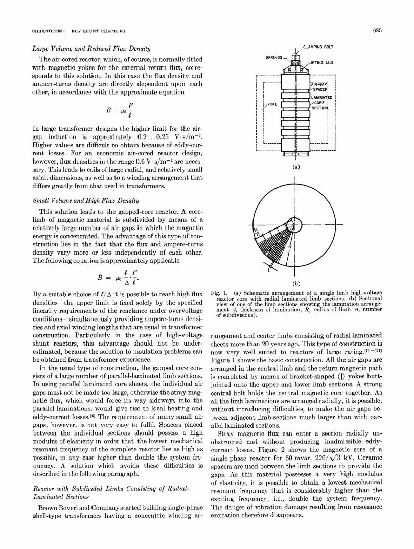
(b)Fig. 1. (a) Schematic arrangement of a single limb high-voltage
reactor core with radial laminated limb sections. (b) Sectionalview of one of the limb sections showing the lamination arrange-ment (t, thickness of lamination; R, radius of limb; n, numberof subdivisions).
rangement and center limbs consisting of radial-laminatedsheets more than 20 years ago. This type of construction isnow very well suited to reactors of large rating.][71-[1Figure 1 shows the basic construction. All the air gaps arearranged in the central limb and the return magnetic pathis completed by means of bracket-shaped ([) yokes butt-jointed onto the upper and lower limb sections. A strongcentral bolt holds the central magnetic core together. Asall the limb laminations are arranged radially, it is possible,without introducing difficulties, to make the air gaps be-tween adjacent limb-sections much larger than with par-allel laminated sections.
Stray magnetic flux can enter a section radially un-obstructed and without producing inadmissible eddy-current losses. Figure 2 shows the magnetic core of asingle-phase reactor for 50 mvar, 220/-\'2- kV. Ceramicspacers are used between the limb sections to provide thegaps. As this material possesses a very high modulusof elasticity, it is possible to obtain a lowest mechanicalresonant frequency that is considerablv higher than theexciting frequency, i.e., double the system frequency.The danger of vibration damage resulting from resonanceexcitation therefore disappears.
685

IEEE TRANSACTIONS ON POWER APPARATUS AND SYSTEMS JUNE 1967
Fig. 2. Single limb core: radial-laminated limb sections for high-voltage shunt reactor, 50 MVA, rated voltage 225/AV3 kV.
Fig. 3. Two-limb core: radial-laminated limb sections for high-voltage shunt reactor, 110 MVA, rated voltage 735/A/3 kV.
Fig. 4. A 165-MVA shunt reactor group in service. Rated voltage735 kV.
For very large ratings and high voltages it may benecessary to change to a 2-limb arrangement. Here too, theradial-laminated core-limb type of construction is possible.as Fig. 3 shows. The yokes are arranged horizontally in thiscase. Because of the precautions that must necessarily betaken to collect stray fluxes, the configuration of theseyokes must be studied particularly closely.As a result of the predominating influence of the air
gap, the impedance characteristic of the reactors describedis linear to a voltage much higher than the rated value. Intransmission networks using series condensers it is alsooccasionally necessary to ask for an impedance character-istic which is substantially linear even at high dynamicovervoltages. These stipulations can be met by an adequatedesign.[10] The radial-laminated construction can also beused for a 3-phase unit having a magnetic circuit similarto that of Fig. 3. An advantage gained is that the zerosequence reactance is only approximately half that of thepositive sequence reactance. In many cases this can havea favorable influence on the power frequency overvoltagesoccurring during a single-phase ground fault.['2] Figure 4shows a 165-MVA group of single-phase units for 735 kV.
TESTS
The various testing specifications[3] are actually ap-plicable to both transformers and shunt reactors. Neverthe-less it has become apparent that these specifications cannotreadily be used for large shunt reactors.[] Compared withthe testing requirements for power transformers, there arethree main differences to be mentioned, namely
1) the difficulty of measuring the losses with satis-factory accuracy
2) the need for special measurements, which on trans-formers are unusual and also unnecessary
3) the demands made upon available power and volt-age sources during heat and induced voltage tests.These difficulties are dealt with in detail in the following
three sections.
Impedance and Loss Measurements
The total losses of a power transformer are determinedin two separate tests, open-circuit and short-circuit. Formodern power transformers, the test power requirementsare less than one percent of rated power for the open-circuit test and approximately 20 percent, as an upperlimit, for the short-circuit test. The situation is quitedifferent in the case of reactors; here there is only oneoperating condition, the open-circuit test, in which theopen-circuit current is simultaneously the full rated cur-rent. It follows automatically that, if the reactor is to beexcited to full rated voltage, full rated power must besupplied by the manufacturer's test plant. In testing high-voltage reactors there is the additional difficulty, because ofthe absence of a secondary low-voltage winding, of alsohaving to supply this high power at high voltage. The prob-lem can only be solved by means of high capital invest-ment on the part of the manufacturer. [141-[16] In addition tothe need for a larger generator, it is necessary to have a
686
CHRISTOFFEL: EHV SHUNT REACTORS
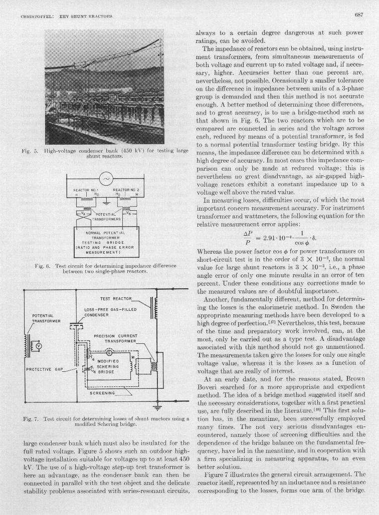
Fig. 5. High-voltage condenser bank (450 kV) for testing largeshunt reactors.
Fig. 6. Test circuit for determining impedance differencebetween two single-phase reactors.
POTENTIALTRANSFORMER
L,
P1R
PROTECTIVE GAP -
TEST REACTOR
LOSS-FREE GAS-FILLEDCONDENSER
PRECISION CURRENTL___ TRANSFORMER
MODIFIED
c SCHERING4 BRiDGE
SCREENING
Fig. 7. Test circuit for determining losses of shunt reactors using amodified Schering bridge.
large condenser bank which must also be insulated for thefull rated voltage. Figure 5 shows such an outdoor high-voltage installation suitable for voltages up to at least 450kV. The use of a high-voltage step-up test transformer ishere an advantage, as the condenser bank can then beconnected in parallel with the test object and the delicatestability problems associated with series-resonant circuits,
always to a certain degree dangerous at such powerratings, can be avoided.The impedance of reactors can be obtained, using instru-
ment transformers, from simultaneous measurements ofboth voltage and current up to rated voltage and, if neces-sary, higher. Accuracies better than one percent are,nevertheless, not possible. Occasionally a smaller toleranceon the difference in impedance between units of a 3-phasegroup is demanded and then this method is not accurateenough. A better method of determining these differences,and to great accuracy, is to use a bridge-method such asthat shown in Fig. 6. The two reactors which are to becompared are connected in series and the voltage acrosseach, reduced by means of a potential transformer, is fedto a normal potential transformer testing bridge. By thismeans, the impedance difference can be determined with ahigh degree of accuracy. In most cases this impedance com-parison can only be made at reduced voltage; this isnevertheless no great disadvantage, as air-gapped high-voltage reactors exhibit a constant impedance up to avoltage well above the rated value.
In measuring losses, difficulties occur, of which the mostimportant concern measurement accuracy. For instrumenttransformer and wattmeters, the following equation for therelative measurement error applies:
AP 1= 2.91 10-4 *8.
P cos4Whereas the power factor cos 0 for power transformers onshort-circuit test is in the order of 3 X 10⁻², the normalvalue for large shunt reactors is 3 X 10⁻³, i.e., a phaseangle error of only one minute results in an error of tenpercent. Under these conditions any corrections made tothe measured values are of doubtful importance.
Another, fundamentally different, method for determin-ing the losses is the calorimetric method. In Sweden theappropriate measuring methods have been developed to ahigh degree of perfection. [171 Nevertheless, this test, becauseof the tine and preparatory work involved, can, at themost, only be carried out as a type test. A disadvantageassociated with this method should not go unmentioned.The measurements taken give the losses for only one singlevoltage value, whereas it is the losses as a function ofvoltage that are really of interest.At an early date, and for the reasons stated, Brown
Boveri searched for a more appropriate and expedientmethod. The idea of a bridge method suggested itself andthe necessary considerations, together with a first practicaluse, are fully described in the literature.[18] This first solu-tion has, in the meantime, been successfully employedmany times. The not verv serious disadvantages en-countered, namely those of screening difficulties and thedependence of the bridge balance on the fundamental fre-quency, have led in the meantime, and in cooperation witha firm specializing in measuring apparatus, to an evenbetter solution.
Figure 7 illustrates the general circuit arrangement. Thereactor itself, represented by an inductance and a resistancecorresponding to the losses, forms one arm of the bridge.
s
687
IEEE TRANSACTIONS ON POWER APPARATUS AND SYSTEMS JUNE 1967
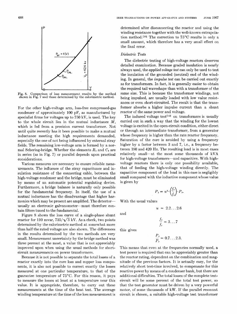
Fig. 8. Comparison of loss measurement results by the methodshown in Fig. 7 and those determined by the calorimetric method.
For the other high-voltage arm, loss-free compressed-gascondenser of approximately 100 pF, as manufactured byspecialist firms for voltages up to 750 kV, is used. The keyto the whole circuit lies in the mutual inductance M,
which is fed from a precision current transformer. Notuntil quite recently has it been possible to make a mutualinductance meeting the high requirements demanded,especially the one of not being influenced by external strayfields. The remaining low-voltage arm is formed by a nor-
mal Schering-bridge. Whether the elements R4 and C4 are
in series (as in Fig. 7) or parallel depends upon practicalconsiderations.
Various measures are necessary to ensure reliable meas-
urements. The influence of the stray capacitance and in-sulation resistance of the connecting cable, between thehigh-voltage condenser and the bridge, must be eliminatedby means of an automatic potential regulating device.Furthermore, a bridge balance is naturally only possiblefor the fundamental frequency. In itself, the use of a
mutual inductance has the disadvantage that higher har-monics which may be present are amplified. The detector-usually an electronic galvanometer must therefore con-
tain filters tuned to the fundamental.Figure 8 shows the loss curve of a single-phase shunt
reactor for 110 mvar, 735/-V- kV. As a check, two pointsdetermined by the calorimetric method at somewhat more
than half the rated voltage are also shown. The differencesin the results determined by the two methods are very
small. Measurement uncertaintv by the bridge method wasthree percent at the most, a value that is not appreciablyimproved upon when using the usual methods for short-circuit measurements on power transformers.
Because it is not possible to separate the total losses of a
reactor exactly into the core loss and copper loss compo-
nents, it is also not possible to correct exactly the lossesmeasured at one particular temperature, to that of theguarantee temperature of 75°C. For this reason, it pays
to measure the losses at least at a temperature near thisvalue. It is appropriate, therefore, to carry out thesemeasurements at the time of the heat test. The average
winding temperature at the time of the loss measurement is
determined after disconnecting the reactor and using thewinding resistance together with the well-known extrapola-tion method.['3] The correction to 75°C results in only asmall amount, which therefore has a very small effect onthe final error.
Dielectric TestsThe dielectric testing of high-voltage reactors deserves
detailed examination. Because graded insulation is nearlyalways used, the applied voltage test can only be used to testthe insulation of the grounded (neutral) end of the wind-ing. In general, the impulse test can be carried out exactlyas for transformers. In fact, it is generally easier to obtainthe required tail waveshape than with a transformer of thesame size. This is because the transformer windings, notbeing impulsed, are usuallv loaded with low value resist-ances or even short-circuited. The result is that the trans-former absorbs a higher impulse current than a shuntreactor of the same power and voltage.The induced voltage test(13] on transformers is usually
carried out in such a way that the winding for the lowestvoltage is excited in the open-circuit condition, either director through an intermediate transformer, from a generatorwhose frequency is higher than the rate reactor frequency.Saturation of the core is avoided by using a frequencyhigher by a factor between 3 and 7, i.e., a frequenev be-tween 180 and 420 Hz. The resulting load is in most casesrelatively small-at the most some thousands of kVAfor high-voltage transformers-and capacitive. With high-voltage reactors there is only one possibility available,that of feeding the high-voltage winding directly. Thecapacitive component of the load in this case is negligiblysmall compared with the inductive component whose valueis given by
=, u2~j. Pr.(fl
With the usual values
u = 2.2 ... .2.6and
ft 3 7.fr
this gives
- 0.7.. .2.3.Pr
This means that even at the frequencies normally used, atest power is required that can be appreciably greater thanthe reactor rating, dependent on the combination and mag-nitude of the previous factors. It is actually easy, for therelatively short test-time involved, to compensate for thisreactive power by means of a condenser bank, but there areadditional difficuilties. The total losses of the complete test-circuit will be some percent of the total test power, sothat the test generator must be driven by a very powerfulmotor, of some thousands of kW. If the parallel resonantcircuit is chosen, a suitable high-voltage test transformer
688s

CHRISTOFFEL: EHV SHUNT REACTORS
is necessary. On the other hand, if the series resonant cir-cuit is favored, there are stability problems which, asalready mentioned, present a certain amount of dangerfor the test object and equipment at these power exchangesIn order that the test-circuit may be regulated with safety,the rating of the test generator should not be less than tenpercent of the total test power required.
Obviously, all these difficulties can be overcome bysufficient capital investment. But now is perhaps the righttime to consider whether the usual transformer inducedvoltage test is a realistic replica of reactor operatingconditions or not. The dynamic overvoltages possible intransmission systems at the highest voltages rarely reachthe factor 1.5 and their duration is at the most someseconds. A decisive influence on the possible shape of theswitching overvoltage is also exerted by the reactor itself.Almost always, lightly damped oscillations of a fewhundreds of cycles, superimposed on the dynamic over-voltage, are involved. These considerations led to thefollowing suggestions. Oscillating overvoltages are com-paratively easy to produce using an impulse generator, asis shown in the simplified circuit of Fig. 9. The chargingand discharging resistances, which must have high values,are not shown. The series resistance Rd controls the wavefront time and also the damping of the oscillations, the fre-quency of which can be adjusted, within certain limits, bythe loading condenser CL. It must also be mentioned thatswitching surge tests of the type being discussed for trans-formerstl9]'[20] are not possible, because in every case therelatively low inductance value of the reactor forces adamped oscillatory discharge of the impulse generator.With impulse generators of normal size, oscillations in therange 250-500 Hz are possible. It would perhaps be appro-priate to carry out two tests, an induced voltage test anda switching surge test, more or less at the same time. Forthe first test the oscillations would be only lightly damped,the damping resistance Rd (Fig. 9) being small and thefront time 10 Ms or less. In Fig. 10(a) the waveshape ob-tained during such a test is shown in which the amplitudeof the first negative overshoot is -80 percent that of thepeak applied voltage. The test level chosen would be thatfor switching surges. In the second test, by suitably in-creasing the value of Rd a front time of 100 ,us, as used forswitching surge tests, would be obtained. In this way thewell-known critical rate of voltage rise, necessary for test-ing the external insulation, would be met and the negativeovershoot would also be very much smaller, as Fig. 10(b)shows. Here, too, the test level would be the same as forswitching surges.What should finally be sufficient proof of a satisfactory
design with respect to dynamic overvoltages is the factthat, in most specifications anyway, a record of the react-ance values at voltages well above the rated value at nor-mal service frequency is required. As the time necessaryfor these measurements is certainly greater than the dura-tion of the dynamic overvoltages, it would also seem ap-priate to make the ionization measurements at the sametime and under the same conditions.
Fig. 9. Circuit for producing damped oscillation by means of animpulse generator. Cg, impulse generator capacitance; Rd, seriesdamping resistance; CL, total effective load capacitance; L, testreactor.
(a)
(b)Fig. 10. Waveshapes obtained with circuit of Fig. 9. (a) Light damp-
ing, relative steep wavefront (1-10 ,us). (b) Heavier damping, lesssteep wavefront (O,100us).
Noise and Vibration MeasurementsCompared with transformers of the same rating, shunt
reactors are distinguished by the many times larger ex-change of magnetic energy. For this reason the designer isforced to devote much more attention to mechanical prob-lems. As pointed out earlier, it is necessary to place themechanical resonances in safe regions. A rigid core and coilassembly having a high resonant frequency is thereforedesirable.A direct measurement of the mechanical resonant fre-
quency is hardly realizable, which means that it is veryimportant to check the mechanical behavior under servicefrequency conditions. Checks on the core and coils duringthe further development of a new design, however, belong
689

IEEE TRANSACTIONS ON POWER APPARATUS AND SYSTEMS JUNE 1967
IIIII,
IIII,IIIIII
--
11i2 46 2242 24~. 97 68
134 1197
Fig. 11. Representation of the results of vibration measurementson a 55-MVA reactor for 735/V/3 kV. The numbers representvibration amplitudes (displacement) in jAm.
to development tests. Nevertheless for the final test, vibra-tion measurements on the tank walls must definitely bemade. A noise test serves in no way at all as a check onsatisfactory mechanical behavior. There are, withoutdoubt, certain relationships between noise level andvibration behavior, but a lower noise level is by no meansa safe guarantee of sufficiently low vibration amplitudes.During the tests at full voltage it is practical to scan thetank with crystal accelerometers for places where thelargest vibration amplitudes occur. Figure 11 shows theresults of such measurements presented in the form usedfor a test report. There are, of course, no generally applica-ble limits to be laid down. It is suggested that the me-chanical stresses at various points oni the tank wall be cal-culated on the basis of the vibration amplitudes measuredat these points. Experience has shown that a stress of 6kp cm-2 represents a safe upper limit.
CONCLUSIONS1) Gapped-core reactors are particularly suited for the
highest voltages; the reactor with radial laminated limbsis marked by a simple construction possessing a high res-onant frequency.
2) Compared with transformers of the same rating, thetesting of large high-voltage shunt reactors places specificdemands with respect to accuracy, high test power, andthe need for special measurements.
3) Wattmeter methods fail for the measurement oflosses at rated voltage and frequency. By observing suit-able precautions it is possible, using a bridge method, toobtain results whose accuracy is of the same magnitude asthat obtained during the measurement of short-circuitlosses on power transformers.
4) Induced voltage tests carried out on transformersbasically can also be performed on reactors. Test plantrequirements for such tests are, however, high. In addi-tion, the test itself has no relation to service conditions.It is therefore suggested that the induced voltage test bereplaced by a test in which a lightly damped oscillatorydischarge occurs from an impulse generator into the reac-
tor. The frequency of this discharge would be between 250and 500 Hz. Satisfactory proof of the ability to withstanddynamic overvoltages would be provided during the im-pedance measurements under overvoltage conditions.
5) As a check on the mechanical behavior of a high-voltage shunt reactor, it is necessary to carry out measure-ments of vibration in addition to those of noise level.
APPENDIXNOMENCLATURE
WmBVV s
AoAruo
F
APCos 4
PtPrftfru
0,
kp
magnetic energyflux densityvolume of the magnetic energy storage devicevolt secondsabsolute permeabilitypermeability of free space (1.25 X 10⁻¹ H.m-')MMF in ampere turnsaxial length of the windingsum of the air gaps in the core limbdifference between actual and measured lossespower factorphase angle error of instrument transformers andwattmeterstest powerrated powertest frequencyrated frequencyovervoltage factor (ratio of the peak values of testand rated voltage)2 7rfkilopond (9.80665 Newton).
REFERENCES[1] G. Jancke, R. Jenkins, B. Nordstrom, and L. Norlin, "The
choice of shunt-reactors for the Swedish 400 kV system," Proc.CIGRE, Rept. 412, 1962.
[2] A. A. Akopjan, U. S. Diskov, S. S. Rokojian, and V. P. Fotin,"Switching over-voltages on long distance 500 kv transmissionlines and measures for limiting them," Proc. CIGRE, Rept. 405,1962.
[3] A. Edlinger, H. Glavitsch, and A. Ritter, "The use of highvoltage reactors for the compensation of extra high voltagetransmission lines," Proc. CIGRE, Rept. 402, 1964.
[4] G. Jancke, "Grundsiitzliche Gesichtspunkte bei der Projekti-rung von Hochspannungs-iubertragungen," Bull SEV, vol. 55,pp. 420-424, May 1964.
[51 A. Goldstein, "Quelques problemes de la transmission de 1'-energie electrique a tre's haute tension (750 kV)," Bull. Soc.Roy. Belge Elect., vol. 81, no. 2, pp. 125-191, 1965.
[6] G. Von Geijer, R. S. Jenkins, B. Sollergren, and R. Myklebust,"Some application, design and testing problems in conjunctionwith large shunt reactors," Proc. CIGRE, Rept. 118, 1964.
[7] A. Meyerhans, "New designs of transformer and chokecoils," Brown Boveri Rev., vol. 32, no. 3, pp. 91-100, 1945.
[8] ,"Radial laminated transformers and reactors," BrownBoveri Rev., vol. 43, no. 6, pp. 187-205, 1956.
[9] ,"A new design for shunt reactors of high rating," BrownBoveri Rev., vol. 45, no. 9, pp. 407-410, 1958.
[10] A. Edlinger, "Transformers and shunt reactors for 750 kV,"Brown Boveri Rev., vol. 51, no. 1/2, pp. 56-67, 1964.
[11] A. Goldstein, "735 kv shunt reactors developed," Elect. World,p. 132, August 23, 1965.
[12] M. Christoffel, "Zero sequence reactance of transformers andreactors," Brown Boveri Rev., vol. 52, no. 11/12, pp. 837-842,1965.
[13] "Test code for distribution, power and regulating transformers,and reactors other than current limitinz reactors," ASA Stand-ard C57.12.90, 1958.
690

CHRISTOFFEL: EHV SHUNT REACTORS
[14]G . W. Alexander, R. H. Hopkinson, and A. U. Welch, "Designand application of EHVshunt reactors," IEEE Trans, on PowerApparatus and Systems, vol. PAS-85, pp. 1247-1258, December1966.
[15] A. Goldstein, "735 kv reactors given extensive testing,"Elect. World, pp. 137-138, October 4, 1965.
[16] W. Erb and D. J. Kraaij, "Design and testing of reactors for735 kv," Brown Boveri Rev., vol. 52, no. 11/12, pp. 864-875,1965.
[171 H. de Bourg, R. S. Jenkins, I. Slettenmarle, C. A. Tengstand,and C. E. Webster, "Calorimetric loss measurements on al-ternators and reactors," Proc.CIGRE, Rept. 119, 1964.
[18] F. Deutsch, "Measuring the active power losses of largereactors," Brown Boveri Rev., vol. 47, no. 4, pp. 268-278,1960.
[19] A. Xlgbrant, A.E. Brierley, N. Hylten-Cavallius, and D. H.Ryder, "Switching surge testing of transformers," IEEETrans. on Power Apparatus and Systems, vol. PAS-85, pp. 54-61, January 1966.
[20] M. Christoffel, "Testing of transformers and reactors withswitching surges," Brown Boveri Rev., vol. 52, no. 4/5, 1966.
Discussion
Frank W. Smith (Tennessee Valley Authority, Chattanooga, Tenn.):This paper is timely and is of particular interest to those of uswho have been involved in preparing specifications for EHV shuntreactors. I would like to comment with regard to the induced test.As the author of this paper states, the induced voltage test does
not truly represent any reasonable system operating condition.Nevertheless, it is our feeling that this is a valuable test which, overthe years, has served a good purpose to the industry. The inducedtest not only subjects the transformer or reactor windings to athorough dielectric stressing, but holds this stress over a significant)eriod of time. Thus, incipient trouble which might not showiiporl impulse or switching surge tests is very apt to be smoked outduring this test. It is my personal opinion that theinduced test is themost significant single dielectric test performed on transformers.While we fully appreciate the problems of the manufacturer inmakiing this test on shunt reactors, we hope that it will riot be toolightly dismissed in favor of a less severe substitute.Shunt reactors are often continuously connected to the system,
and the loss factor is high. It is, therefore, important that the userknow the losses associated with this equipment and evaluate themproperly. It is encouraging to see the efforts of the author in thedirection of accurate measurement of reactor losses.
Manuscript received Jtuly 25, 1966.
A. U. Welch (General Electric Company, Pittsfield, Mass.): Asmight be inferred from Alexander et al.,['41 (referred to in the paper),we agree that the gapped-core reactor is best suited to the manyrequirements of EHV shuLnt service; our experience includes thedesign and manufacture of all the major types.An important virtue of the gapped-core reactor inot mentioned by
the author is the opportunity it provides the designer to matchaccurately the core reluctance distribution with the coil ampere-turndistribution. This is demanded by the same reasons that demandaccurate match of ampere-turn distribution in windings of trans-formers; poor distribution results in large orthogonal magneticfields, stray losses, and local hot spots. The EHV insulation require-ments preclude uniformity of ampere-turn distribution in any typeof winding. Steel shell enclosed, coreless reactor coils have uniformreluctance; the consequent mismatch can produce severe local
heating in the coils, and increased coil vibration, unless specialprecautions are taken.The same argument proves the undesirability of using a small
number of large gaps, as the resulting large wave-like pattern oftransverse flux in the winding has the same unfortunate effects.It is true that flux fringing losses in the steel core blocks are less whenall flux enters the sheets edgewise, but there is still considerableexcess loss at gaps and this is greatly exaggerated by the use oflarge gaps. It will be seen that fringing at the sharp corner wouldresult in infinite flux densit.y if there were no saturation, actually thecorner saturates early in the cycle, and a wave of saturation movesup and down the edges of the steel sheets. The use of short blocks andgaps more than balance the effect of all-edge-oni punchings and,further, it reduces coil stray losses.Some undue concern with the subject of reactor tank vibration
has been generated by the mention in the literature[7 of someearly reactors, in which an elementary preliminary design calculationof magnetic force vs. magnetic shell stiffness would have predictedunacceptable vibration. Few modern reactors are likely to have thisproblem. The important question is whether internal vibration islow enough to permit long life of insulation.
Years of experience with large power transformers indicate thatsound level is generally the best criterion of safe internal vibration,and that equipment that meetsindustry sound level specifications isdependable. Sound measurements in effect integrate most of thevibrational energy as it drives the air surrounding the tank. Soundlevel turns out to be essentially independent of the stiffness of thetank wall. It is true that stiffening may reduce the amplitude of wallvibration, but it does not change sound level or interinal vibration.Stiffening merely alters the vibrational patterns of an otherwiseflexible wall; it may or may not reduce tank stress; to the degreethat it reduces external vibration measurements, it may be mis-leading to the purchaser.As to insulation testing, experience on several EHV reactors has
proven the stability and ease of control of the series resonancemethod of induced potential test. It is only necessary to precomputeaccurately the number of capacitors required to match the reactorand generator reactance. This kind of homework is desirable for anyinisulation testing. This is the only test which provides assurance ofmeaningful measurements of ionization or radio noise. A reactorwould have to be in sad condition indeed to show corona at themaximum power frequency voltage.
M. Christoffel: The author is grateful for the valuable contributionsto the discussions made by Mr. Smith anid Mr. Welch. It is en-couraging to hear that the efforts made to measure the losses ofshunt reactors with much greater accuracy are appreciated. Withregard to the induced voltage test, I am quite in agreement withMr. Welch that, at some expense, this test is technically possible.I also agree completely with MVIr. Smith that the test is a strenuousone. On the other hand I am, as before, of the opinion that it isInot arealistic test and believe that in the fourth conclusion a good al-ternative has been suggested.With reference to the optimum size of the air gaps in core-type
reactors, I am not in agreement with Mr. Welch. In the usual form,the limb of a core-type reactor consists of series core sections, eachof which is parallel laminated as in normal transformer cores. Withthis construction, however, the total air gap must be subdivided intoa large number of individual air gaps. As a result of the parallelarrangement of the core sheets, the flulx at the edges of the air gapscuts across the surface of the sheets instead of entering the edges.The local eddy currents thus caused can only be kept within ac-ceptable limits by a sufficient number of small air gaps. Saturationeffects in the limb sections and additional stray losses in the windingsplay, on the contrary, absolutely no part. Our investigations have
eManuscript received September 30, 1966.
691
Manuscript received Jtily 28, 191,56.

IEEE TRANSACTIONS ON POWER APPARATUS AND SYSTEMS VOL. PAS-86, NO. 6 JUNE 1967
shown, and tests carried out have confirmied, that the last mentionedeffect alone allows a much greater air gap. With the radial-laminiatedtype of construction of the central limb, the first type of eddy-current effect disappears completely, which allows the optimumvalue for the length of the individual air-gaps to be chosenl withregard to the electrical and magnetic considerations.
Concerning the vibrational effects, I am completely in agreementwith Mr. Welch that the all-arounid noise level represents a good
yardstick for assessing the vibration of the core and coils. Thesame result can, however, be obtained more accurately with one ormore built-in accelerometers, as is required from time to time incustomers' specifications. On the other hand, I believe, even if thevibration of the core and coils is satisfactory, that it is essential tosupplement the noise measurement with vibration measurements atvarious points on the tank wall, because it is not certain that in-admissable vibrations do not occur there.
Performance of Line Insulators Under Rime IceM. M. KHALIFA, MEMBER, IEEE, AND R. M. MORRIS, SENIOR MEMBER, IEEE
Abstract-Single suspension insulator units of several typesas well as multi-unit strings were studied in a large refrigeratedchamber. Rime ice of various densities was deposited on theseinsulators. The increase of leakage currents, the reduction of flash-over voltages, and the alteration of voltage distributions along insula-tor strings caused by the presence of the ice were measured. Theeffects of various protective coatings on the insulator performancewere examined. The process of insulator flashover under rime ice iscompared with that under the usual types of industrial and marinepollution at temperatures above freezing point.
INTRODUCTION
S OME TRANSMISSION line outages which have beenexperienced in winter seasons in the west coast areas of
Canada and the U.S.A. have been caused by rime icecovering line insulators.1] In one instance, a reduction inthe operating voltage from 315 to 280 kV was necessaryto keep the lines in service under such conditions.Two possible reasons for the reduction of insulation
strength under rime ice are examined here. One of these isthe increase of the insulator leakage currents and the otheris the disturbance of the patterns of voltage distributionalong insulator strings. This paper describes a laboratorystudy of leakage currents, flashover voltages, and otherperformance characteristics of insulators as influenced bythe density and the electrical conductivity of the rimeice. Although the field conditions were not exactly re-produced in the laboratory-because the rating of thetransformer and the size of the sprayiing set were limited-essentially the same reduction of insulation strength as thatexperieinced in the field could be reproduced.
Paper 31 TP 66-98, recommended and approved by the Transmis-sion and Distribution Committee of the IEEE Power Group for pre-sentation at the IEEE Winter Power Meeting, New York, N.Y.,January 30-February 4, 1966. Manuscript submitted August 16,1965; made available for printing November 24, 1965.The authors are with the Division of Radio and Electrical Engi-
neering, National Research Council of Canada, Ottawa, Canada.
INSULATORS TESTED
The tests were carried out on porcelaiin and glass in-sulators of the standard cap-and-pin type, on porcelainantifog anid on long-rod insulators, Fig. 1. The lengths ofthe leakage paths per insulator unit were 113/4, 17, and 96inches for the standard, antifog, and long-rod insulators,respectively. The long-rod insulator was compared with astring of seven standard porcelain units, both having thesame rated voltage of 63.5 kV (110/x/3). Some tests werealso made on standard porcelain insulators with annularbands of semi-conducting glaze around the pins.
FORMATION AND PROPERTIES OF RIME ICE
Rime ice is known to be formed in nature by the freezingof supercooled cloud or fog-water droplets on objects ex-posed to the cloudy or foggy atmosphere. It covers the ob-jects by an amorphous coating containing air voids andhaving a density ranging between 20 and 50 lb/ft3.
In the present tests, rime ice could be reproduced in arefrigerated chamber 15 by 25 by 12 feet high, where thetemperature could be closely controlled. After ensuringthat the chamber contents were at about 0°F, distilled ortap water was sprayed with heated compressed air onitothe insulators from a special set of nozzles about 15 feetaway. The water drops cooled on their way from the nozzlesto the insulator surface where they collected as rime ice.The ice coating was made as uniform as possible by rotatingthe insulators periodically while sprayinig. The density ofthe ice formed could be controlled between 25 and 48 lb/ft3by adjustiilg the temperature of the compressed air. Theelectrical conductivity of samples of the ice was measuredand was found to increase with the ice density and tem-perature, Fig. 2. It was lower for ice made of distilledthan of tap water although the difference diminished asthawing was approached. This may be attributed to thetraces of foreign materials carried by the distilled water
692