07.12.2004iwbs04 / j. wenninger1 orbit stabilization at the large hadron collider (lhc) introduction...
Post on 18-Dec-2015
214 views
TRANSCRIPT

07.12.2004 IWBS04 / J. Wenninger 1
Orbit Stabilization at Orbit Stabilization at the Large Hadron Collider (LHC)the Large Hadron Collider (LHC)
• Introduction to the LHC• Stabilization issues and requirements• Expected sources of perturbations• Overview of the BPM-corrector system• Conclusions
J. Wenninger CERN
Accelerators and Beams DepartmentBeam Operation Group
There will be a ‘follow-up’ talk by R. Steinhagen :‘Large scale orbit correction for the LHC’

07.12.2004 IWBS04 / J. Wenninger 2
Orbit feedback at a hadron machine ?Orbit feedback at a hadron machine ?
Hadron machines are usually not ‘famous’ for their orbit stabilization systems.
This is explained by the fact that the main aim of orbit correction in hadron machines is….
… to keep the beam in the pipe !
The LHC is not really different in that respect, but the LHC ‘pipe’ and what is circulating inside are special :
• The LHC is a complex superconducting machine.• The LHC magnets are very sensitive to beam loss.• The LHC will explore new territory in terms of stored beam energy.

07.12.2004 IWBS04 / J. Wenninger 3
LHC overviewLHC overview BEAM 1clockwise
BEAM 2counter-clockwise
The LHC is a superconducting proton and ion collider with design luminosity of 1034 cm-2 s-1
The LHC will be installed in the former 26.7 km long LEP tunnel.
The LHC consists of 2 rings that cross in 4 interaction reagions :
• 2 high lumi exp. (CMS / ATLAS) • 2 low lumi exp. (ALICE / LHC-B)
Each ring has 8 arcs and 8 long straight sections.
Energy range :• Injection at 450 GeV/c• Collisions at 7 TeV/c

07.12.2004 IWBS04 / J. Wenninger 4
LHC overview / 2LHC overview / 2CMS
ATLAS
The tunnel extends fromGeneva airport to the Jura mountain.
Tunnel depth is 70-140 m.
The ‘natural’ noise spectrum in the tunnel is very low (it is adequate for a linear collider).
CERN site

07.12.2004 IWBS04 / J. Wenninger 5
Superconducting magnetsSuperconducting magnets
Special 2-in-1 design : One magnet for the 2 beams.
To reach the nominal field of 8.33 T, the Nb-Ti dipoles magnets are operated at 1.9 K (super-fluid He) with a current of 12 kA.
The magnet aperture is 56 mm.
A consequence of the ‘extreme’ design:• At 7 TeV the magnets are operated
very close to the quench limit.• A fast beam loss of less than one part
per 107 of the beam may quench a magnet.
The recovery time from a quench at 7 TeV is ~ 6 hours.

07.12.2004 IWBS04 / J. Wenninger 6
LHC beam parametersLHC beam parameters
Beam structure (protons) :Beam structure (protons) :
• Bunch separationBunch separation 25 ns (or multiples)25 ns (or multiples)
• Bunch intensityBunch intensity 55××101099 to 1.1 to 1.1××101011 protons protons
• Number of bunchesNumber of bunches 1 – 28081 – 2808
function :function :
• Arcs (max)Arcs (max) 180 m180 m
• Insertions (max)Insertions (max) ~ 5000 m~ 5000 m
• Interaction region Interaction region * * 18 m (injection) 18 m (injection) 0.5 m 0.5 m (collisions)(collisions)
Emittance (round beam) :Emittance (round beam) :
• 450 GeV450 GeV 7.7 nm7.7 nm
• 7 TeV7 TeV 0.5 nm0.5 nm
Beam size at 7 TeV (rms) :Beam size at 7 TeV (rms) :
• Arcs Arcs 300 µm300 µm
• Interaction regionInteraction region 15 µm15 µm
Bunch length at 7 TeV (rms) : 8 cm

07.12.2004 IWBS04 / J. Wenninger 7
Energy stored in the LHC beamsEnergy stored in the LHC beams• The energy stored in each LHC beam exceeds by more than 2 orders of magnitude
that of any existing machine : 350 MJ stored / each beam.• The transverse energy density / brightness is even a factor 1000 higher.
0.01
0.10
1.00
10.00
100.00
1000.00
1 10 100 1000 10000Momentum [GeV/c]
En
erg
y s
tore
d i
n t
he
be
am
[M
J]
LHC topenergy
LHC injection
ISR
SNSLEP2
SPS fixed target
HERA
TEVATRON
SPSppbar
LHC injection from SPS
Factor~200
RHIC proton
Sufficient to melt500 kg of Cu
-
Equivalent of :
• 90 kg of TNT
• 25 kg of sugar

07.12.2004 IWBS04 / J. Wenninger 8
What you can do with 1% of the energy What you can do with 1% of the energy stored in the LHC beam…stored in the LHC beam…
Chamber is cut over ~ 20 cm
Signs of heating over ~ 1 m
Impact of a 450 GeV/c protonbeam corresponding to ~ 2 MJ
into a quadrupole chamber
Simulated T increase ~ 1400˚ C

07.12.2004 9
Operation cycleOperation cycle
0
2000
4000
6000
8000
10000
12000
-4000 -2000 0 2000 4000
time from start of injection (s)
dip
ole
cu
rre
nt (
A)
energy ramp
beam dump
coastcoast
450 GeV
7 TeV
12 injectionsper ring
ramp start
squeeze = 18 m 0.5 m

07.12.2004 IWBS04 / J. Wenninger 10
Beam collimationBeam collimation
Due to head-on and long range beam-beam as well as non-linearities, particles will drift to large amplitudes.
To prevent quenches of the SC magnets, the collimation system has to catch 99.99% of all particles that drift out of the machine. This is orders of magnitude better than what is required at existing proton machines.
Due to limited apertures near the interaction regions, the primary collimators must be closed to 5-7 constraints on orbit stability.
The primary collimator aperture at injection
and top energy.
There will be ~ 120 collimators jaws at the LHC

07.12.2004 IWBS04 / J. Wenninger 11
Collimation & protection requirementsCollimation & protection requirements
The very high demands on collimation and the need for protection of the machine against uncontrolled beam loss sets the hardest constraints on stabilization.
In particular we must maintain the alignement of the beam wrt collimator jaws and absorbers / protection devices that are separated by many kms.
Collimation inefficiency versus position error
• In the 2 collimation sections (over a distance of few 100 meters) :
< 0.3 70 m
• At protection devices installed in 6 long straight sections :
< 0.5 100-400 m
Stabilization requirements

07.12.2004 IWBS04 / J. Wenninger 12
Vacuum chamberVacuum chamber
Beam 3 envel. ~ 1.8 mm @ 7 TeV
50.0 mm
Beam screen
36 mm
450 GeV ~ 10 7 TeV ~ 40
Vac. Ch. aperture
Machine aperturefor collisions
~ 10-12
The vacuum chamber is protected by a beam screen operated at T = 4-20 K :• intercepts synchrotron radiation (total power 3.6 kW, enery loss per turn 7 keV)• carries image currents.
Cooling channel (He)

07.12.2004 IWBS04 / J. Wenninger 13
Electron cloudsElectron cloudsAffect beams with positive charge, high intensity and short bunch spacing :Affect beams with positive charge, high intensity and short bunch spacing :
• Vacuum pressure increase.
• Energy deposition : at the LHC the deposited power may exceed the 1 W/m (at 4 K) cooling capacity of the vacuum chamber.
• Beam stability : head-tail and coupled bunch.
‘‘Electron clouds’ are due to multipacting inside the vacuum chamber and depend on Electron clouds’ are due to multipacting inside the vacuum chamber and depend on the surface properties (secondary emission yield).the surface properties (secondary emission yield).
Multipacting can be cured by ‘cleaning’ of the chamber with the beamMultipacting can be cured by ‘cleaning’ of the chamber with the beam – run with high – run with high multipacting for a sufficient amount of time.multipacting for a sufficient amount of time.
But the chamber cleaning is ‘local’ (around the orbit) But the chamber cleaning is ‘local’ (around the orbit) stabilization to ~ 0.5 mm rms stabilization to ~ 0.5 mm rms to operate within the ‘cleaned’ areas.to operate within the ‘cleaned’ areas.

07.12.2004 IWBS04 / J. Wenninger 14
Requirement overviewRequirement overview
Stabilization requirements : Excellent (for the proton world) global control during all operational phases :
• RMS change < 0.5 mm.
Tight constraints around collimators and absorbers :
• RMS change < 50-70 m for nominal performance.
The only demanding requirement from 2 special experiments :
• Stability of ~ 5-10 m over 12 hours around their IR – feasability must be demonstrated (BPM performance).
Dominant sources of orbit perturbations : Ground motion.
Dynamic effects from superconducting magnets.
Beta squeeze.

07.12.2004 IWBS04 / J. Wenninger 15
Ground motionGround motion
Long term orbit drifts (LEP) : ~ 200-500 m rms over a few hours~ 20-50 m rms over ~ minute(s)
a priori we expect similar figures for the LHC !
orbit rms ground movement
Uncorrelated motion : 35 Ground waves :
f < 5 Hz 1f > 5 Hz 1 < < 100
CO movements at f > 0.1 Hz are expected to be 20 m !
1 m
1 nm
OPAL cavern
IP4
LEP/LHC tunnel noise spectrum
Assuming that :
The LEP/LHC tunnel is a fortunately a quiet place…

07.12.2004 IWBS04 / J. Wenninger 16
‘‘Snapback and decay’Snapback and decay’in superconducting magnetsin superconducting magnets
The orbit is affected by random dipole (b1, a1) and quadrupole (b2) errors :
1-4 mm rms change in the both planes
Start of ramp
~ 50 secSnapback~ 900 sec decay
@ injection
Example of the b3 / sextupole error • Long lasting inter-strand eddy currents due to
field ramps (persistent currents) have a strong effect on the field quality of the magnets – issue at injection.
• Affect orbit, tune, chromaticity (~ 90 units)….
• Time dependence :
Decay on the injection plateau.
‘Snapback’ at ramp start.
• At injection the magnetic machine is not stable for the first ~ 30 minutes.
07.12.2004 IWBS04 / J. Wenninger 17
Other perturbationsOther perturbations
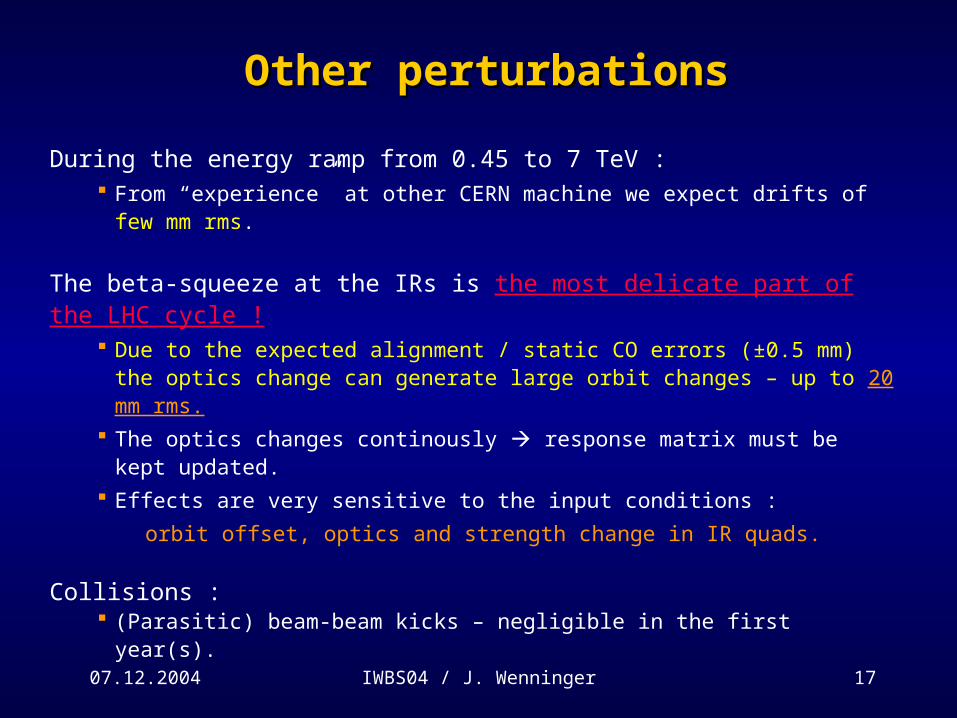
During the energy ramp from 0.45 to 7 TeV : From “experience” at other CERN machine we expect drifts of few mm rms.
The beta-squeeze at the IRs is the most delicate part of the LHC cycle ! Due to the expected alignment / static CO errors (±0.5 mm) the optics change can
generate large orbit changes – up to 20 mm rms.
The optics changes continously response matrix must be kept updated.
Effects are very sensitive to the input conditions :
orbit offset, optics and strength change in IR quads.
Collisions : (Parasitic) beam-beam kicks – negligible in the first year(s).
07.12.2004 IWBS04 / J. Wenninger 18
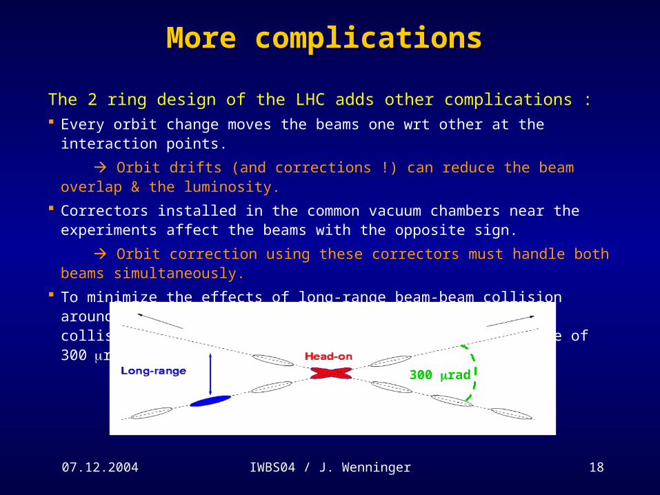
More complicationsMore complications
The 2 ring design of the LHC adds other complications : Every orbit change moves the beams one wrt other at the interaction points.
Orbit drifts (and corrections !) can reduce the beam overlap & the luminosity.
Correctors installed in the common vacuum chambers near the experiments affect the beams with the opposite sign.
Orbit correction using these correctors must handle both beams simultaneously.
To minimize the effects of long-range beam-beam collision around the collision points (~30 encounters around each collision point), the beams collide with a crossing angle of 300rad.
300 rad

07.12.2004 IWBS04 / J. Wenninger 19
Beam position measurementsBeam position measurements
• 528 BPMs (Horizontal + Vertical) per ring.• There is one BPM at each quadupole, except in the collimation sections where there is one
BPM on both sides of each quadrupole.• In the arcs the phase advance between BPMs is 45˚ - sampling is OK.
• Acquisition based on ‘Wideband Time Normalizer’ principle (CERN design) : Full bunch-by-bunch acquisition (40 MHz system). RT orbit sampling at up to 50 Hz – averaged over one 50 Hz period (225 turns). Orbit resolution < 1 m for nominal intensity. Multiturn acquisitions of up to 100k turns / BPM.
• BPM system issues : Residual intensity / bunch length dependence of measurements may reach ~ 100 m. Influence of hadronic showers on the signal of BPMs near collimators. Interference RT / multiturn acquitions. Reliability ?
07.12.2004 IWBS04 / J. Wenninger 20
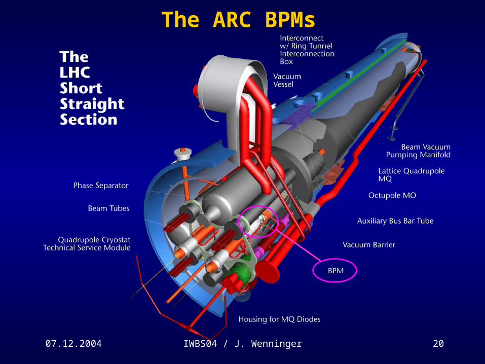
The ARC BPMsThe ARC BPMs

07.12.2004 IWBS04 / J. Wenninger 21
The ARC BPMs / 2The ARC BPMs / 2

07.12.2004 IWBS04 / J. Wenninger 22
Steering magnetsSteering magnets
There are 280 orbit corrector magnets per ring and per plane.
Most (> 90%) of the orbit correctors are superconducting magnets : Circuit time constants = L/R 10 to 200 s slow !!! EVEN for SMALL signals, the PC bandwidth is ~1 Hz. At 7 TeV : ~ 20 m oscillation / corrector @ 1 Hz.
The PCs are connected over a real-time fieldbus (WoldFip) to the gateways that control them – the bus operation is limited to 50 Hz.
Consequence :
The LHC orbit FB will operate at up to 50 Hz - more likely at 25 Hz.
But this sampling rate is adequate given the expected perturbations !

07.12.2004 IWBS04 / J. Wenninger 23
Feedback layout Feedback layout
FB
The monitors, correctors and their electronics are installed at the 8 LHC access points – spread over 27 km data transport is an issue.
To achieve the best flexibility, we have opted for a centralized FB design :
• Corrections will be performed in one central location – global & local corrections.
• The data is transported over Gigabit Ethernet.
• Note : for a combined (2 ring) global correction the matrix size is up to ~ 1050 x 560.
Details will be described in R. Steinhagen’s presentation :
‘Large scale orbit correction for the LHC’

07.12.2004 IWBS04 / J. Wenninger 24
SummarySummary
• The LHC is the first hadron collider that requires a real-time orbit feedback.
• The main reasons for a feedback are the collimation requirements of the high intensity
beams inside a superconducting machine.
• The difficulty at the LHC arises from the large geographical distribution of equipment and
the complexity of the 2 rings.
• The FB system will be operated at up to 25-50 Hz – for initial operation with low intensity a
frequency of 0.1-1 Hz will be sufficient.
• The reliability of the orbit FB must be high – a quench of a magnet at 7 TeV ‘costs’ around 6
hours of recovery time.
• More details on the design will be given by R. Steinhagen.

07.12.2004 IWBS04 / J. Wenninger 25
ArchitectureArchitecture
Central entire information available. all options possible. can be easily configured and adapted.…network more critical – DELAYS ! large amount of network connections. …
FB
FB
FB
FB
FB
FB
FB
FB
FB
Local reduced # of network connections. numerical processing simpler. … less flexibility. not ideal for global corrections. coupling between loops is an issue. problem with boundary areas to ensure closure. ..

07.12.2004 IWBS04 / J. Wenninger 26
LEP slow orbit driftsLEP slow orbit drifts
The measured slow LEP orbit drifts give a good indication of what to expected at the LHC no problem for a FB running at 0.5 Hz or more.
1 band
Average LEP orbit drift
100 mat the LHC
RMS drift (m, = 1 m) versus time

07.12.2004 IWBS04 / J. Wenninger 27
3-stage collimation3-stage collimation
Primarycollimators
Secondary collimators
Protection devices
Cold aperture Strategy:
Primary collimators are closest.
Secondary collima-tors are next.
Absorbers for protec-tion just outside se-condary halo before cold aperture.
Relies on good knowledge and control of the orbit around the ring!

07.12.2004 IWBS04 / J. Wenninger 28
LHC beam dumping systemLHC beam dumping system
Q5R
Q4R
Q4L
Q5L
Beam 2
Beam 1
Beam Dump Block
Septum magnets(V deflection)
H-V kickers to paint the
beam
~ 700 m
~ 500m
15 kicker magnets
(H deflection)
IR6
The beam dumping system has a high-reliability interlock system since any malfunction can have very severe
consequences for the LHC machine.

07.12.2004 IWBS04 / J. Wenninger 29
Beam dump blockBeam dump block
concrete shielding
beam absorber (graphite)
7 m
The dump block is the only element of the LHC able to
absorb the full 7 TeV beam !

07.12.2004 IWBS04 / J. Wenninger 30
LHC Amplitude to Time Normaliser SchematicsLHC Amplitude to Time Normaliser Schematics
INPUT OUTPUT
A A
BB
T1 = 1.5 ns
T1 = 1.5 ns

07.12.2004 IWBS04 / J. Wenninger 31
Wide Band Time NormalizerWide Band Time Normalizer
-2.5
-2.0
-1.5
-1.0
-0.5
0.0
0.5
1.0
1.5
Time [ns]
Am
plitu
de A
-1.0
-0.5
0.0
0.5
1.0
1.5
2.0
2.5
3.0
Am
plitu
de B
A B
A+(B+1.5ns)
B+(A+1.5ns)+10ns
System outputInterval = 10 1.5ns