0762p kingspan insulated panels in cool rooms · web viewits wide range of products include...
TRANSCRIPT
07 MECHANICAL 0762p KINGSPAN INSULATED PANELS in cool rooms
0762P KINGSPAN INSULATED PANELS IN COOL ROOMS
1 GENERAL
1.1 RESPONSIBILITIES
GeneralRequirement: Provide refrigerated cool rooms using KINGSPAN Insulated Panels, as documented.
1.2 COMPANY CONTACTS
KINGSPAN technical contactsWebsite: https://www.kingspan.com/au/en-au/products-brands/insulated-panel-systems/contact-en.
1.3 CROSS REFERENCES
GeneralRequirement: Conform to the following:
- 0171 General requirements.
- 0701 Mechanical systems.
- 0771 Automatic controls.
- 0781 Mechanical electrical.
1.4 STANDARDS
GeneralRefrigeration systems: To AS/NZS 5149.1, AS/NZS 5149.2, AS/NZS 5149.3 and AS/NZS 5149.4.
Cool rooms for food storage: To AS 4674.
1.5 MANUFACTURER'S DOCUMENTS
Technical manualsBrochures and technical information:
- Downloads: https://www.kingspan.com/au/en-au/products-brands/controlled-environments/coldstore-systems.
- Technical support: https://www.kingspan.com/au/en-au/products-brands/insulated-panel-systems/contact-en.
1.6 INTERPRETATION
AbbreviationsGeneral: For the purposes of this worksection the following abbreviations apply:
- CS: KINGSPAN Controlled Environments Panel.
- KIP: KINGSPAN Insulated Panels.
- PIR: Polyisocyanurate.
DefinitionsGeneral: For the purposes of this worksection the following definitions apply:
- BMS: Building management system.
- Cool room: A refrigerated space which is designed to maintain a temperature below 5°C and is used primarily for the storage of product.
© NATSPEC (Apr 19) 1 "[Insert date]"
07 MECHANICAL 0762p KINGSPAN INSULATED PANELS in cool rooms
1.7 SUBMISSIONS
CertificationStructural and trafficable ceilings: Submit certification of the ceiling from a structural engineer.
Fire performanceCombustibility: Submit evidence of conformance to PRODUCTS, FIRE PERFORMANCE, Combustibility.
Fire hazard properties: Submit evidence of conformance to PRODUCTS, FIRE PERFORMANCE, Fire hazard properties.
Fire-resistance level: Submit evidence of conformance to PRODUCTS, FIRE PERFORMANCE, Fire-resistance of building elements.
Products and materialsThermal insulation properties: Submit evidence of conformance to AS/NZS 4859.1 and AS/NZS 4859.2.
Type tests: Submit results, as follows:
- Cyclone performance: KS1100 CS wall panel.
- Refrigeration equipment.
SamplesGeneral: Submit a sample of each of the following:
- Wall to wall to ceiling corner joint.
- Panel to panel joint.
Cutaway sections: For each sample, provide cutaway sections to permit inspection of application details including insulation materials, adhesives, mastics and fixings.
SubcontractorsApproved installers: Submit the name and contact details of the proposed KINGSPAN approved installer.
TestsPre-completion tests: Submit test results for the following:
- Pressure testing of refrigeration equipment.
WarrantiesMaterials: Submit KINGSPAN product warranty with corresponding inspection and maintenance document.
Workmanship: Submit a warranty on the installation of the wall and/or ceiling system.
1.8 INSPECTION
NoticeGeneral: Give notice so that inspection may be made of the following:
- Floor slab: Ready for installation of subbase.
- Heated subbase: Complete and before commencing floor laying.
- Vapour barrier: Installed with locating angle in position ready for wall panel installation.
- Membrane: Installed ready for placing wearing surface.
© NATSPEC (Apr 19) 2 "[Insert date]"
07 MECHANICAL 0762p KINGSPAN INSULATED PANELS in cool rooms
2 PRODUCTS
2.1 GENERAL
Product substitutionOther products: Conform to PRODUCTS, GENERAL, Substitutions in 0171 General requirements.
Product identificationGeneral: Marked to show the following:
- Manufacturer’s identification.
- Product brand name.
- Product type.
- Quantity.
- Product reference code and batch number.
- Date of manufacture.
Storage and handlingRequirement: Store and handle materials to the KINGSPAN recommendations and the following:
- Provide a safe and trade free area for the storage of KINGSPAN materials.
- Remove KINGSPAN protective film within the time stipulated on the face of each insulated panel.
- Protect materials including edges and surfaces from damage.
- Keep dry and unexposed to weather including protection from direct sunlight.
- Do not drag metal sheets or panels across each other or over other materials.
- Composite panels: Store unpacked panels by size in racks on a slight slope to prevent ponding on panel surfaces. Protect from scratching, warping or bending.
Operating conditionsGeneral: Provide equipment that operates within an ambient temperature range of 0°C to 45°C, without excessive head pressure or unstable operation.
SealantsMaterials: One-component compounds with a neutral curing mechanism, vulcanising at room temperature. Provide sealants that:
- Do not foster microbial growth.
- Maintain their sealing performance for the life of the cool room.
- Bond to the surface of application without primers.
- Are resistant to oils, food acids and water after curing.
- Are non-toxic.
- After curing retain their elastomeric properties over the range of room operating temperatures.
- Are suitable for application by gun or hand tools.
Corrosion protectionFerrous metals: Either stainless steel or protected from corrosion by hot-dip galvanizing or metallic coating.
Fasteners: Stainless steel or non-ferrous only.
FastenersPrimary fasteners: Provide high threaded self-drilling, self-tapping screws with bonded washers, as follows:
© NATSPEC (Apr 19) 3 "[Insert date]"
07 MECHANICAL 0762p KINGSPAN INSULATED PANELS in cool rooms
- Types, sizes and drilling capacity: As recommended by fastener manufacturer to suit type and thickness of supports, and thickness of cladding panels.
- Screw material: Type 316 austenitic stainless steel.
- Washer material: Non-ferrous.
- Washer size: 16 mm diameter.
- Heads: Plastic moulded or lacquered.
Secondary fasteners: Provide fasteners for internal flashing installation at 300 mm centres, as follows:
- Screw/washer material: As primary fasteners.
- Heads: Low profile, painted to match colour of the flashing.
Mushroom bolts: Provide mushroom bolts with threaded rod, lock nut and plastic cover.
Rivets: Expanding solid end type 4.8 mm diameter.
Screws: Self-tapping, self-drilling.
Number, type and location of fasteners: To suit project to KIP Technical Services recommendations.
RefrigerantsRequirement: Provide refrigerants as follows:
- Listed as Safety Group A1 or A2L in AS/NZS ISO 817.
- Ozone Depletion Potential: 0.
- Global Warming Potential: ≤ 700.
Factory Mutual (FM) panel system approvalKINGSPAN controlled environment panel systems: Approved to FM 4880 and FM 4881.
2.2 FIRE PERFORMANCE
CombustibilityFiremaster panels: Not deemed combustible when tested to AS 1530.1.
Fire hazard propertiesGroup number: To AS 5637.1.
Wall and ceiling panels: Tested to AS/NZS 1530.3. Fire hazard properties as follows:
- Ignitability Index: 0.
- Heat evolved Index: 0.
- Spread-of-Flame Index: 0.
- Smoke-Developed Index: 2.
Materials with reflective facing: Test to AS/NZS 1530.3 and the recommendations of Appendix A6.
Fire-resistance of building elementsFire-resistance level: Tested to AS 1530.4.
2.3 PRE-COMPLETION TESTS
StandardsGeneral: Provide refrigeration equipment that has been subjected to a physical test in conformance to the following:
- Pressure tests: To AS/NZS 5149.2.
- Type tests: Factory type test packaged refrigerating plant for capacity and operating performance.
2.4 KINGSPAN KS1100 CS CONTROLLED ENVIRONMENTS PANEL CONSTRUCTION
© NATSPEC (Apr 19) 4 "[Insert date]"
07 MECHANICAL 0762p KINGSPAN INSULATED PANELS in cool rooms
PanelsRequirement: Provide KINGSPAN KS1100 CS insulated wall and ceiling panels.
Construction: Prefinished metal skins continuously laminated over a polyisocyanurate (PIR) core.
Panel to panel joints: KINGSPAN proprietary jointing system except for cut panels. Make sure the visible facing joint engages with a gap of less than 3 mm so the foam faces form a butt joint and maintain an effective seal.
Insulation: Polyisocyanurate (PIR) in continuous form without voids and free of line faults through or across the sheet.
Thermal conductivity: ≤ 0.020 W/(m.K).
Blowing agents: Do not provide materials:
- Which use CFC or HCFC as blowing agents in the manufacturing process.
- Which use a blowing agent with a global warming potential ≥ 140.
Internals and external skinsMaterial: 0.5 mm zinc-coated steel sheet to AS 1397, coating class Z275 Zincform G300S, factory pre-coated on the exposed surface.
Factory pre-coating: Antibacterial, 25 micron thick
Colour: White.
Panel profile: Flat or ribbed as documented.
FlashingsPrefabricated flashings: Minimum 0.5 mm metallic-coated steel to AS 1397 manufactured to suit the selected coating.
DimensionsPanel thickness: To suit the temperature difference across the panel and to KIP Technical Services recommendations.
Panel width:
- Standard module cover width: 1100 mm.
- Non-standard module cover width: 1200 mm.
Ceiling panelsThickness: To Dimensions except where the ceiling is trafficable or serves a structural function.
Structural and trafficable ceilings: If the ceiling is trafficable or serves a structural function, provide certification from a professional engineer that the thickness and construction is adequate for the imposed loads and meets statutory requirements.
TestsCyclone performance of KS1100 CS wall panels: Tested to 15 kPa wind loading to AS 4040.3.
2.5 EUROBOND FIREMASTER PANEL CONSTRUCTION
GeneralRequirement: Provide Eurobond Firemaster insulated wall and ceiling panels, as documented.
FM panel system approval: Certified for installation without a height restriction to FM 4880 Class 1 Fire Rating of Building Panels.
Construction: Prefinished metal skins continuously laminated over a mineral wool core.
Panel to panel joints: Firemaster proprietary jointing system except for cut panels.
Insulation: Non-combustible mineral wool in continuous form without voids and free of line faults through or across the sheet.
© NATSPEC (Apr 19) 5 "[Insert date]"
07 MECHANICAL 0762p KINGSPAN INSULATED PANELS in cool rooms
Blowing agents: Do not provide materials:
- Which use CFC or HCFC as blowing agents in the manufacturing process.
- Which use a blowing agent with a global warming potential ≥140.
Panel thickness: To suit the temperature difference across the panel and to KIP Technical Services recommendations.
Panel width:
- Standard module cover width: 1100 mm.
Accessories: Flashings, trims, drips, cappings to match/contrast as required (available via Eurobond Doors).
Firemaster Wall Lite systemExternal facing material:
- Flat (non-ribbed) 0.5 mm white foodsafe laminate or white polyester.
- Substrate: ZA275 hot-dip zinc coated steel.
- Metal thickness: 0.5 mm total coated thickness.
- Finish: PE25 white polyester.
- Colour RAL9010.
Internal facing material:
- 0.5 mm steel pre-coated galvanised steel finish.
- Finish: PE25 white polyester.
- Colour: RAL9010.
Panel thickness available: 100 to 240 mm as documented.
Thermal conductivity: ≤ 0.042 W/(m.K).
Sound transmittance of cladding/covering system: Minimum weighted sound reduction index (Rw) within 100 to 3150 Hz frequency range.
- 100 mm: 31 Rw dB.
- 125 mm: 32 Rw dB.
- 150 mm: 32 Rw dB.
- 175 mm: 33 Rw dB.
- 200 mm: 34 Rw dB.
- 240 mm: 34 Rw dB.
Accessories: Provide the following:
- Primary fasteners: Self-drilling and tapping stainless steel screws.
- Number and location of fasteners: Minimum of three fasteners at each end of panel.
Fixing guns: Use fixing guns with depth gauges provide correct compression of the fixings and no distortion of the panel face.
Firemaster Wall ExtraExternal facing material:
- Flat (non-ribbed) 0.5 mm white foodsafe laminate or white polyester.
- Substrate: ZA275 hot-dip zinc coated steel.
- Metal thickness: 0.5 mm total coated thickness.
- Finish: PE25 white polyester.
- Colour RAL9010.
© NATSPEC (Apr 19) 6 "[Insert date]"
07 MECHANICAL 0762p KINGSPAN INSULATED PANELS in cool rooms
Internal facing material:
- 0.5 mm steel pre-coated galvanised steel finish.
- Finish: PE25 white polyester.
- Colour: RAL9010.
Panel thickness available: 75 to 240 mm as documented.
Thermal conductivity: ≤ 0.044 W/(m.K).
Sound transmittance of cladding/covering system: Minimum weighted sound reduction index (Rw) within 100 to 3150 Hz frequency range.
- 75 mm: 31 Rw dB.
- 100 mm: 31 Rw dB.
- 125 mm: 33 Rw dB.
- 150 mm: 34 Rw dB.
- 175 mm: 35 Rw dB.
- 200 mm: 36 Rw dB.
- 240 mm: 36 Rw dB.
Accessories: Provide the following:
- Primary fasteners: Self-drilling and tapping stainless steel screws.
- Number and location of fasteners: Minimum of three fasteners at each end of panel.
Fixing guns: Use fixing guns with depth gauges provide correct compression of the fixings and no distortion of the panel face.
Firemaster Wall UltimaExternal facing material:
- Flat (non-ribbed) 0.7 mm white foodsafe laminate or white polyester.
- Substrate: ZA275 hot-dip zinc coated steel.
- Finish: PE25 white polyester.
- Colour RAL9010.
Internal facing material:
- 0.7 mm steel pre-coated galvanised steel finish.
- Finish: PE25 white polyester.
- Colour: RAL9010.
Panel thickness available: 150 to 240 mm as documented.
Thermal conductivity: ≤ 0.044 W/(m.K).
Sound transmittance of cladding/covering system: Minimum weighted sound reduction index (Rw) within 100 to 3150 Hz frequency range.
- 150 mm: 34 Rw dB.
- 175 mm: 35 Rw dB.
- 200 mm: 36 Rw dB.
- 240 mm: 36 Rw dB.
Accessories: Provide the following:
- Primary fasteners: Self-drilling and tapping stainless steel screws.
- Number and location of fasteners: Minimum of three fasteners at each end of panel.
© NATSPEC (Apr 19) 7 "[Insert date]"
07 MECHANICAL 0762p KINGSPAN INSULATED PANELS in cool rooms
Fixing guns: Use fixing guns with depth gauges provide correct compression of the fixings and no distortion of the panel face.
Eurobond Ceiling Panel SystemCeiling profiles: Minibead (top), architecturally flat or minibead (bottom), as documented.
External facing material:
- Flat (non-ribbed) 0.5 mm white foodsafe laminate or white polyester.
- Substrate: ZA275 hot-dip zinc coated steel.
- Metal thickness: 0.5 mm total coated thickness.
- Finish: PE25 white polyester.
- Colour RAL9010.
Internal facing material:
- 0.5 mm steel pre-coated galvanised steel finish.
- Finish: PE25 white polyester.
- Colour: RAL9010.
Sound transmittance of cladding/covering system: Minimum weighted sound reduction index (Rw) within 100 to 3150 Hz frequency range.
- 75 mm: 31 Rw dB.
- 100 mm: 33 Rw dB.
- 125 mm: 33 Rw dB.
- 150 mm: 34 Rw dB.
- 175 mm: 35 Rw dB.
- 200 mm: 36 Rw dB
- 240 mm: 36 Rw dB
Thickness: To suit the required FRL and span.
Joints: Provide panels with interlocking steel joint detail.
Structural and trafficable ceilings: If the ceiling is trafficable or serves a structural function, provide certification from a professional engineer that the thickness and construction is adequate for the imposed loads and meets statutory requirements.
Accessories: Provide the following:
- Ceiling Suspension System: Eurobond Proprietary System
- Support location: To be advised based on spanning capabilities and FRL requirements. Please contact KIP Technical Services for project specific advice.
2.6 DOORS
Door assemblyType: Sliding or hinged panels as documented that close against a door frame. Provide all necessary door hardware, gaskets and the like.
Escape provisions: Provide the following:
- Access doors openable from both the inside and outside.
- If the door is electrically or pneumatically operated provide a means for opening the door manually.
- One of the following:
. A telephone in every room.
. Unlocked insulated safety exit door which can only be opened from the inside.
© NATSPEC (Apr 19) 8 "[Insert date]"
07 MECHANICAL 0762p KINGSPAN INSULATED PANELS in cool rooms
. A panel removable from the door or adjacent wall from the inside of the room making an opening large enough for a person to pass through easily.
Thermal performance: Provide doors and door sets which, when closed, have thermal insulation properties equal to those of the wall in which they are located.
Seal: Provide face sealing doors.
Sill-less doors: If the door has no sill, provide a mechanism to elevate the door clear of the floor surface during opening and closing.
Door panelConstruction: Provide doors of panel type construction, free of studding with skins bonded to both sides of an insulation core.
Insulation: Conform to PANEL CONSTRUCTION.
Insulation thickness: Same thickness as the wall in which the door is located.
Edging: Form door edging from a heavy gauge aluminium extrusion with double web seal to both skins. Mitre corner and firmly secure to panel stainless steel with countersunk head screws.
Viewing panelType: Triple glazed, vacuum insulated with thermally broken aluminium frame.
Size: As documented.
Finish: Powder coated frame to match the door finish.
Anti-condensation heater cablesHeater cables: Incorporate a thermal break and dual heater cables (1 spare) to prevent condensation on outside face of door. Locate heater cables at door seals.
Type: 230 V self temperature regulating heating cable terminating in coiled tails. Provide earth leakage protection.
Installation: Install heating cables, accessible for replacement, in the door frame and threshold.
Heater cable section below doors: Locate heater cables as follows:
- Cool room door threshold flush with external floor: Locate heater cable in a channel formed in the external floor between two 25 mm x 25 mm x 3 mm aluminium angles recessed into the floor. Provide polyurethane packing below the heater cable and removable silicone seal above it.
- Cool room door threshold higher than the external floor: Locate heater cable in a removable angle or Z section on the external face of the cool room, below the door threshold. Fix section with countersunk stainless steel screws.
Door frameConstruction: Form frame stiles and head from 3 mm aluminium or 10 mm PVC-U extrusions incorporating rebates if required for door seating. Mitre corners and fix frame firmly to the inner and outer wall skins. Maintain the vapour seal of the wall panel. Make suitable provision for fixing the specified hardware.
Heater cables: Incorporate a thermal break and dual heater cables (1 spare) to prevent condensation on outside face of door.
ThresholdConstruction: Aluminium checker plate 200 mm wide x 2.5 mm thick. Fix to the floor across the full width of the door opening.
GasketsConstruction: Provide naturally resilient, non-hygroscopic neoprene or silicone rubber gaskets with not less than 2 prongs. Fix to the door using a method that allows easy removal and replacement.
© NATSPEC (Apr 19) 9 "[Insert date]"
07 MECHANICAL 0762p KINGSPAN INSULATED PANELS in cool rooms
Door protectionRequirement: If door protection is documented, provide 2.5 mm thick embossed aluminium checker plate, the width of the door, to both sides of the door and to a height of 1200 mm.
2.7 EMERGENCY ACCESS DOORS
GeneralRequirement: Conform to DOORS with the following exception:
- Locks: Openable from inside the cool room only.
2.8 DOOR HARDWARE
CatchesConstruction: Provide externally lockable door catches with overriding internal safety release mechanism and internal handles for closing of door.
HingesHinged doors: Hang hinged doors on edge mounted, rising butt type, self closing hinges capable of holding the door fully open.
Materials: Heavy duty brass or gunmetal, chromium plated to AS 1192, service condition number 2, satin finish, for catches, hinges, handles and similar items.
Sliding trackSliding doors: Hang sliding doors on an overhead sliding track mechanism of capacity suitable to the door, comprising an extruded aluminium track section, top carriages and bottom roller guides with turned nylon ballbearing rollers and a door height adjustment mechanism. Provide heavy duty rubber stops at both ends of the door travel.
InstallationFixing: Securely bolt hardware to the door and frame. Minimise cold bridging and formation of condensation on the outside of the cool room.
Alarm bellBell: Provide a manually operated bell on the door with the operating mechanism on the inside and the bell on the outside. Recess the operating mechanism so that it is flush with the inside face of the door.
2.9 REFRIGERATION PLANT GENERALLY
ConstructionRequirement: Provide one or more complete packaged systems per room consisting of condensing and evaporator units, designed and rated by the manufacturer to operate together.
Refrigeration system typesType: Provide refrigeration systems as documented of the following types:
- Split system: Two piece package system with separate evaporator and air cooled condensing unit.
Selection: Select system components to match the documented capacities and to operate without excessive saturated suction temperature.
- Single drop in unit: Drop in or slide in unit, self contained one piece factory sealed unit, fully wired and complete with all controls.
ComponentsRequirement: Provide the following for each system:
- Air cooled condensing unit.
- One or more evaporators with fans.
- Automatic controls.
© NATSPEC (Apr 19) 10 "[Insert date]"
07 MECHANICAL 0762p KINGSPAN INSULATED PANELS in cool rooms
- Capacity control on systems over 30 kW(R).
- Manual reset high pressure and auto reset low pressure cutouts.
- High and low side test points.
- Associated refrigerant and drain piping.
- Refrigeration plant power circuits.
- Vibration isolating mountings.
- Pressure relief to AS/NZS 5149.2.
- Phase failure protection on motors ≥ 5.5 kW.
- Permanent, weatherproof, wiring diagram fixed on or next to the control panel.
Split systems: Provide in addition:
- Liquid line solenoid valve.
- Liquid-suction heat exchanger.
- Thermostatic or electronic expansion valve.
- Compressor service valves.
- Integral positive temperature coefficient type crankcase heaters if required for safe compressor operation. Energise when the compressor is off.
- Schrader type connections for evacuation and refrigerant charging.
- Evaporator isolating valves.
- Test valves.
- Liquid receiver with service valves. Size to hold the full refrigerant charge.
- Suction line vibration eliminator.
- Replicable filter-dryer.
- Low oil pressure cutout.
- Liquid line sight glass and moisture indicator.
- Room temperature ≤ 0°C: Provide also:
. Crankcase pressure regulator.
. Liquid line accumulator with liquid heat exchanger.
. Insulated oil separator.
2.10 EVAPORATORS
DescriptionGeneral: Provide low-silhouette evaporators which include an extended surface aluminium finned copper cooling coil with externally mounted externally equalised expansion valve, refrigerant distributors, one or more fan and motors, air outlet baffles, insulated stainless steel or aluminium condensate drain pan and accessories. Locate the expansion valve bulb or sensor to the valve manufacturer's recommendations.
Type: Low profile induced draft (IDC) or forced draft (FDC).
Casing: Stainless steel or heavy gauge aluminium.
CoilsFins: ≤ 236 fins per m.
Room air to coil temperature difference: ≤ 5 K.
Face velocity: ≤ 2.5 m/s.
© NATSPEC (Apr 19) 11 "[Insert date]"
07 MECHANICAL 0762p KINGSPAN INSULATED PANELS in cool rooms
FansType: Axial flow, aluminium blade, propeller with an IP54 motor, class E insulation and inbuilt auto-resetting overload protection.
Noise level in room with all fans operating: ≤ 65 dB(A).
Installation: Provide a corrosion resistant fan guard and aerodynamic contoured tube housing. Provide easy access to each fan and motor for inspection and maintenance.
Air delivery: Direct to the room with a throw of not less than three quarters of the room length.
Motors: ≥ 0.37 Kw: Three phase only.
HeatersRoom operating temperature ≤ 2°C: Provide coil defrost heaters and drain pan heaters consisting of totally enclosed sheathed heater elements, in banks designed for separate and easy removal in the case of failure. Provide dual heater circuits.
Heater size: ≤ 15% of evaporator cooling capacity.
2.11 CONDENSING UNITS
DescriptionType: Provide packaged condensing units comprising liquid receiver, compressor, hot gas line, condenser and accessories. Mount the components on a common grid corrosion protected steel base.
Room operating temperature ≤ 0°C: In addition, provide the following:
- Open surge tank suction accumulator.
- Back pressure regulator.
- Oil separator.
Compressor typesType: Provide open type compressors as follows and as documented:
- Belt drive.
- Direct drive.
- Semi-hermetic.
- Hermetic.
Hermetic and semi-hermetic compressorsEnclosure: Welded or accessible hermetic steel enclosure with minimum 3 mounting feet. Provide the following:
- Mounting: Vibration isolating mountings.
- Service valves: Packed and capped, backseating refrigerant suction valve.
- Charging connections: Schrader type connections for evacuation and refrigerant charging.
Crankcase heaters: Provide integral positive temperature coefficient type crankcase heaters if required for safe compressor operation.
Scroll compressors: Provide reverse rotation protection.
GaugesRequirement: If documented, provide suction and discharge pressure gauges to nominated condensing units.
Air cooled condensersCondenser coils:
- Tubes: Copper to AS/NZS 1571 or AS 1572 designation C12200.
- Fins: Aluminium alloy plate fins ≥ 0.12 mm thick to AS 2848.1, designation 3003 or 8011.
© NATSPEC (Apr 19) 12 "[Insert date]"
07 MECHANICAL 0762p KINGSPAN INSULATED PANELS in cool rooms
- Fin pitch: ≤ 550 fins/m.
- Subcooling: > 5K.
Propeller fan: Direct drive with single thickness fixed pitch aluminium or ultraviolet light protected polypropylene blades.
Aerofoil axial flow fan: Direct drive with adjustable pitch aerofoil section blades of ultraviolet light protected glass reinforced plastic or polypropylene, or aluminium.
Fan motors:
- Over 0.37 kW: Three phase.
- Speed: < 25 rev/s.
- Bearings: Sealed for life ball bearings.
- Minimum degree of protection: IP55.
Head pressure control: Provide head pressure control by fan cycling .
Water cooled condensersType: Mechanically cleanable shell and tube condensers with steel end plates and shells and copper or copper alloy extended surface tubes.
Performance rating: Rate to AHRI 450.
Design pressures:
- Water side: ≤ 1000 kPa.
- Refrigerant side: To AS/NZS 5149.2.
Drain and vent: Provide valved water side drain and vent connections to each condenser.
Compressor cooling: If the compressor is not refrigerant cooled, provide a compressor cooling fan.
Sacrificial anodes: Provide sacrificial anodes conforming to AS 2129 and AS 2239 in the condenser water boxes to protect all ferrous metals.
Head pressure control: Provide a water flow control valve to maintain head pressure.
Condensing unit enclosureRequirement: If documented, provide an enclosed powder coated casing enclosure rated at IP54 to nominated condensing units. Arrange to be easily removable for service.
2.12 SHELVING
GeneralShelving: Provide proprietary adjustable modular shelving as follows:
- Posts: 25 x 25 x 1.2 mm cold rolled angle section with 25 mm diameter foot with 65 mm height adjustment. Provide slotted holes at regular centres in the posts for shelf height adjustment.
- Shelf frames: 32 x 2.5 mm cold rolled angle section at front and rear.
- Wire grid shelves: Welded frame with 4 mm wires at 25 mm centres supported on 8 mm centre and edge bars.
- Dunnage shelves: Welded frame with 25 x 25 x 1.6 mm square hollow section (SHS) tubes at 65 mm centres.
Material: Metallic-coated steel, hot-dip galvanized steel or stainless steel as documented.
© NATSPEC (Apr 19) 13 "[Insert date]"
07 MECHANICAL 0762p KINGSPAN INSULATED PANELS in cool rooms
3 EXECUTION
3.1 INSTALLATION
Substrates or framingPreparation: Before fixing cladding, check the alignment of substrates or framing and adjust if required.
Execution detailsConstruction details: Conform to KIP Technical Services recommended construction details.
KIP Technical Services recommendations: Conform to KINGSPAN recommendations and use KINGSPAN approved installers for installation. Conform to the following:
- Fasteners, seals and fillers: Install as documented.
- Site cut panels:
. Provide accurate, true lines with no distortion.
. Cut with a suitable metal cutting circular type saw and treat exposed edges with a suitable edge protection lacquer.
- Openings: Cut to the minimum size necessary.
- Penetrations: Cut to the minimum size necessary.
- Edge reinforcement: Provide trimming plates.
- General: Install neatly and accurately, and to suit sizes and edge details of fittings.
- Services: Position services accurately, support adequately. Align and level in relation to the ceiling and suspension system and correctly seal maintaining the vapour barrier and continuity of insulation. Do not diminish performance of ceiling system.
- Penetrations up to 300 mm: Supported by ceiling panel.
- Penetrations for ducting, access hatches, etc: Support independently and provide flanges to support ceiling system.
- Swarf: Remove swarf and any foreign matter immediately from the external surface of panels.
- Protection: Protect surfaces and finishes, including the retention of protective coatings during installation.
JointsGeneral: Provide aluminium extrusions or steel flashings of the same material as the panel skin internally and externally:
- At panel junctions except where KINGSPAN proprietary panel to panel joint is used.
- Make sure the visible facing joint engages with a gap of less than 3 mm so the foam faces form a butt joint and maintain an effective seal.
- Between panels and building structures, if documented.
Sealant: Apply a continuous bead of sealant along extrusions to form an airtight seal.
Floor joint: Provide a steel angle or F extrusion base mould with mitred corners at the base of walls. Fix at 400 mm centres to Professional engineer's recommendations.
Panel butt jointingGeneral: Join using KINGSPAN proprietary panel to panel joint with sealant applied to inside and outside to KIP Technical Services recommendations.
Cut panelsPosition: Locate cut panels at the corners of the room.
© NATSPEC (Apr 19) 14 "[Insert date]"
07 MECHANICAL 0762p KINGSPAN INSULATED PANELS in cool rooms
Joint typesVertical corner joints: Create a rebate for one panel to receive the other to KINGSPAN standard details to provide continuous insulation contact.
Wall to ceiling joints: Form a rebate in the wall panel to receive the ceiling panel. If panels join at the corner without a rebate, cut back the internal skin of the panel that is receiving the other panel for the width of the panel thickness.
Floor insulation to wall joint: Remove the inside skin of the cool room floor wall panels for the height of the floor insulation to form insulation continuity without gaps.
Joint coversExternal wall and ceiling joint cover: Provide 50 x 50 mm extruded aluminium angle or 0.55 mm steel angle of the same material and finish as the panel skin.
Internal wall and ceiling joint cover: Coved aluminium extrusion or 0.55 mm steel angle of the same material and finish as the panel skin.
Internal floor joint cover: Coved aluminium extrusion.
Joint cover fixing: Fix the joint covers to panels with sealed blind rivets.
Panel penetrationsConstruction: Provide flanged PVC-U sleeves for service penetrations through wall and ceiling panels. Fill the void between the service and the sleeve with a one component polyurethane sealant. Vapour seal to the panel. Provide a plastic flange to the sleeve on the outside of the panel and vapour seal to the panel.
External flashingConstruction: Provide extruded aluminium cove moulding not less than 25 mm radius, as a flashing moulding between the external wall skin and the external floor.
Internal wall protectionRequirement: If documented, provide wall protection to internal walls of the cool room.
Cool rooms with no shelving:
- Concrete wearing surface floor: Provide a 50 mm x 50 mm x 3 mm hot-dip galvanized RHS rail 100 mm from the wall. Support rail 100 mm above the finished floor on 44 mm x 6 mm hot-dip galvanized brackets at ≤ 1500 mm centres.
- Aluminium checker plate or plywood wearing surface: Provide 4 heavy duty 100 mm x 25 mm extruded aluminium bump rail sections fixed horizontally to the full width of each wall. Locate at 250 centres vertically with the lowest bump rail 100 mm above the floor.
Cool rooms with shelving: Provide heavy duty 100 mm x 25 mm extruded aluminium bump rail sections fixed horizontally to the full width of the wall. Provide one per shelf at a height to suit the shelving.
High ambient humidity environmentsRequirement: If KS1100 CS Controlled Environments panels are installed in situations where ambient humidity could cause condensation, provide the following:
- Intermediate supports in high humidity applications: Seal along purlins using two unbroken runs of sealant tape or neoprene foam tape: 4.8 mm x 60 mm wide.
- Coating for High humidity internal environments other than swimming pools): AQUAsafe.
- Coating for swimming pools environments: AQUAsafe55.
Firemaster Lite/Extra/ Ultima:
- Contact Kingspan Insulated Panels for project specific recommendation for high humidity environments.
© NATSPEC (Apr 19) 15 "[Insert date]"
07 MECHANICAL 0762p KINGSPAN INSULATED PANELS in cool rooms
3.2 SEALING
SealantsType: Use a mastic sealant for internal mating surfaces and a sealant as a secondary vapour barrier on external joints.
Vapour sealingConstruction: Form a continuous external vapour barrier around the cool room by vapour sealing the external wall and ceiling joints and penetrations, and by sealing the locating section to the base of the wall panels and to the vapour barrier membrane.
Water sealingConstruction: Form a waterproof joint between walls and floor wearing surfaces by sealing the internal cove and external flashing mouldings to the respective wall and floor surfaces. Seal internal butt and corner joints up to 1 m above the floor to facilitate cleaning.
3.3 PRESSURE RELIEF
Relief portRequirement: For all rooms with an operating temperature not more than 0°C provide two relief ports in one wall.
Construction: Square aluminium body in a PVC-U sleeve with internal vertical hinged PVC-U vanes.
Size: ≥ 150 x 125 mm.
Heater: Provide an electric heater in each relief port to prevent malfunction resulting from freezing.
3.4 CEILING SUPPORT
Execution detailsRequirement: Conform to KIP Technical Services recommendations.
Ceiling joints over internal wallsOverlap: If ceiling panels butt join over internal wall panels, locate the ceiling joint not less than 25 mm from the face of the wall panels.
3.5 HEATED FLOOR SUBBASE
Heated subbaseRequirement: Provide a heated subbase incorporating a heating mat over the floor slab under cool rooms as follows:
- Under all cool rooms constructed on suspended floors.
- Under all room with an operating temperature not more than 0°C.
Heating matConstruction: Provide a heating mat with twin overlapping circuits, each of 100% of the required heating capacity.
Cables: 230 V self-temperature regulating heating cable, factory-assembled into mats each with not more than 500 mm between adjacent coils and terminating in cold tails.
Output of heating mat: 15 W/m2.
Mat installationLocation: Lay the mats on insulated spacers to cover the whole floor area to within 200 mm of the walls.
Termination: Terminate the tails in a junction box located on the inside wall of the room.
© NATSPEC (Apr 19) 16 "[Insert date]"
07 MECHANICAL 0762p KINGSPAN INSULATED PANELS in cool rooms
Screed: Embed the heating mats in a 1:3 cement: sand screed to provide not less than 25 mm minimum cover. Provide a smooth level surface finish, free of loose material and projections, suitable for receiving the vapour barrier membrane.
TestingContinuity: Test the heating mat cables for electrical continuity:
- Before laying the screed.
- Continuously during the laying process and for the following 24 hours.
Method: Use a continuity warning device temporarily connected to the circuits during this period.
Tanking optionTanking: If documented, provide bituminous sheeting over the sub base or sub-floor and sides of a rebated floor. Lap all joints 150 mm. Install to the manufacturer's recommendations
3.6 FLOOR VAPOUR BARRIER MEMBRANE
GeneralMaterial: Polyethylene film branded continuously:
- AS 2870 CONCRETE UNDERLAY 0.2 mm HIGH IMPACT RESISTANCE.
InstallationGeneral: Install as follows:
- Lay over the base, lap joints at least 200 mm and seal the laps and penetrations with non-hardening mastic spread in a continuous strip 75 mm wide.
- Tape over joints with polyethylene pressure-sensitive adhesive tape, applied without wrinkles. Face the laps away from the direction of concrete pour.
- Patch or seal punctures or tears before pouring concrete. Cut back as required after concrete has gained strength and forms have been removed.
Base preparation: Remove projections above the plane surface, and loose material.
Locating section: Fix over the vapour barrier membrane, extruded aluminium angles mitred at the corners to form a locating frame for positioning the walls of the cool room. Fix the locating frame by securing to the sub-floor using masonry anchors. Vapour seal the fastener penetration with sealant before inserting the fastener.
Vapour seal: Apply continuous mastic sealant between locating section and vapour barrier membrane and between the locating section and the wall panels.
3.7 FLOORS
Concrete wearing surfaceConstruction: Lay rigid cellular polyurethane sheet insulation to AS 1366.1 over the whole of the internal floor area tightly fitted without gaps immediately above the vapour barrier membrane. Lay the insulation boards in two layers using ship-lapped joints.
Insulation thickness:
- Room operating temperature > 0°C: ≥ 100 mm (2 layers each 50 mm).
- Room operating temperature ≤ 0°C: ≥ 150 mm (2 layers each 75 mm).
Aluminium checker plate or plywood wearing surfaceFloors with an aluminium checker plate or plywood wearing surface: Provide floor insulation in the form of prefabricated panels to PANEL CONSTRUCTION, bonded to the wearing surface. Lay panels immediately above the vapour barrier membrane and tightly fitted without gaps.
Insulation thickness:
© NATSPEC (Apr 19) 17 "[Insert date]"
07 MECHANICAL 0762p KINGSPAN INSULATED PANELS in cool rooms
- Room operating temperature > 0°C: ≥ 100 mm.
- Room operating temperature ≤ 0°C: ≥ 150 mm.
3.8 RECESSED COOL ROOM FLOORS
GeneralGrout: If the cool room floor is recessed into a slab such that a space exists between the cool room wall panels and slab, grout the space.
3.9 WATERPROOF MEMBRANE
GeneralMembrane and sealing: Conform to FLOOR VAPOUR BARRIER MEMBRANE.
Installation: Lay the membrane over the floor insulation with 150 mm overlaps at the joints. Turn the edges up against the wall inner skin, to the lesser of a height of 50 mm or the top of the cove moulding.
3.10 FLOOR WEARING SURFACE
GeneralRequirement: Provide a wearing surface to:
- Accept the floor in service loads without damage to the floor insulation.
- With a hard wearing surface finish.
Grading: Grade the surface to doorway.
Cool rooms for food storage: To AS 4674 Section 3.
Concrete wearing surfaceConstruction: Provide a concrete slab reinforced with steel fabric to AS/NZS 4671 SL72 mesh. Locate the fabric to provide a top cover of 25 mm, by means of reinforcement supports, chairs, blocks or supports resting on metal or plastic chairs, blocks or supports.
Coving: Provide a 75 mm radius cove in the concrete at the junction between the wearing surface and the wall inner skin. Finish the cove under an aluminium coving angle. Seal gaps to SEALING.
Concrete strength: 40 MPa.
Entrained air: If the room operating temperature is not more than 0°C, conform to AS 3600 clause 4.7.
Maximum aggregate size: 10 mm.
Slab thickness: ≥ 75 mm.
Finish: Provide a finish to the concrete conforming to the following:
- As laid concrete: Finish the concrete surface in a slip-resistant finish by trowelling silicone carbide or aluminium oxide grains into the surface.
- Epoxy coating: Apply a 3 mm thick slip-resistant epoxy coating to the floated concrete surface.
- Steel tiles: Bed and grout steel tiles to the concrete surface.
- Ceramic tiles: Requirement: Bed and grout selected slip-resistant ceramic tiles to the concrete surface.
Plywood wearing surfaceConstruction: Provide 20 mm thick marine plywood to AS/NZS 2272, formaldehyde emission class E1 or lower, bonded to the floor insulation metal skin. Apply a 3 mm thick slip-resistant epoxy coating to the marine plywood.
Coving: Provide an extruded aluminium cove moulding, not less than 25 mm radius at the junction between the wearing surface and the wall inner skin. Seal gaps to SEALING.
© NATSPEC (Apr 19) 18 "[Insert date]"
07 MECHANICAL 0762p KINGSPAN INSULATED PANELS in cool rooms
3.11 REFRIGERANT PLANT
GeneralAccess for maintenance: To ACCESS FOR MAINTENANCE in 0171 General requirements.
Vibration suppression: To VIBRATION SUPPRESSION in 0171 General requirements.
EvaporatorsLocation: Mount the evaporator below the ceiling, with 450 mm between the wall and the rear of the evaporator and at least 2100 mm clearance under.
Support: Suspend the unit from cold rolled metallic coated steel bearers mounted above the room. Extend the bearers to the cool room walls and size. Size bearers to suit the load and span.
Hardware: Nylon or stainless steel to suit the load.
Condensing unitsVibration isolation: Mount each condensing unit on 4 vibration isolators.
Support: Support condensing units on either a concrete plinth or hot-dip galvanized steel frame securely fixed to the wall, floor or slab above using anchor bolts.
Arrangement: Provide clearance around units for condenser air flow and maintenance access. Make sure discharge air does not short-circuit to condenser intake.
Plinths: If located on grassed or similar permeable surfaces, provide concrete plinths under outdoor equipment.
Refrigerant leak detectionRequirement: Provide refrigerant leak detection to AS/NZS 5149.3.
Sensors: To GAS SENSORS, Refrigerant Sensor in 0771 Automatic controls.
3.12 REFRIGERATION PIPING
GeneralRequirement: Conform to equipment manufacturer's recommendations for the refrigerant used. Provide refrigeration piping designed and installed so that the complete system meets the documented performance and operating conditions.
DesignSuction lines: Size for pressure drop less than 1.0 K saturated suction temperature.
Oil return: Size for oil return to compressor. Where velocity for oil return would result in the suction line pressure drop exceeding pressure drop limit, provide double suction risers. Prevent oil draining back during the off cycle.
Liquid lines: Size for pressure drop of less than 1.0 K saturated liquid temperature when handling the manufacturer's unit capacity under the operating temperatures stated in the schedules.
LayoutGeneral: Install pipework in straight lines and uniform grades without sags. Grade horizontal hot gas lines and suction lines at not less than 1 in 200 in the direction of gas flow.
Location: When possible, run suction and liquid lines inside common insulation.
Connections to vibrating equipment. Provide flexibility to resist vibration by way of coiled pipe connections or braided hose.
Pipe supportGeneral: Conform to the following:
- Provide hangers, brackets, saddles, clips, and support system components, incorporating provisions for adjustment of spacing, alignment, grading and load distribution.
- Support pipework from associated equipment or building structure.
© NATSPEC (Apr 19) 19 "[Insert date]"
07 MECHANICAL 0762p KINGSPAN INSULATED PANELS in cool rooms
- Support valves, strainers and major line fittings so that no load is placed on adjacent tubes or transmitted to them during operation and maintenance.
Support type: Proprietary metallic-coated steel channel section with clamps and hangers sized match external diameter of pipe being supported.
Stand-off brackets: If pipes are exposed within the cool room or in food preparation areas, support on brackets to provide the clearances from adjacent surfaces to AS 4674, clause 3.2.9.
Vertical pipes: Provide anchors and guides to maintain long pipes in position, and supports to balance the mass of the pipe and its contents.
Saddles: Do not provide saddle type supports for pipes more than DN 25.
Uninsulated pipes: Clamp piping supports directly to pipes.
Insulated pipe support:
- Spacers: Provide spacers at least as thick as the insulation between piping supports and pipes. Extend either side of the support by at least 20 mm.
- Spacer material: Rigid insulation material of sufficient strength to support the piping and suitable for the temperature application.
- Vapour barriers: For cold pipes apply aluminium foil tape over the circumference of the spacer to form a vapour barrier.
- Metal sheathing: Provide a 0.55 mm thick metallic-coated steel band between the aluminium foil tape and the support, for the full width of the spacer.
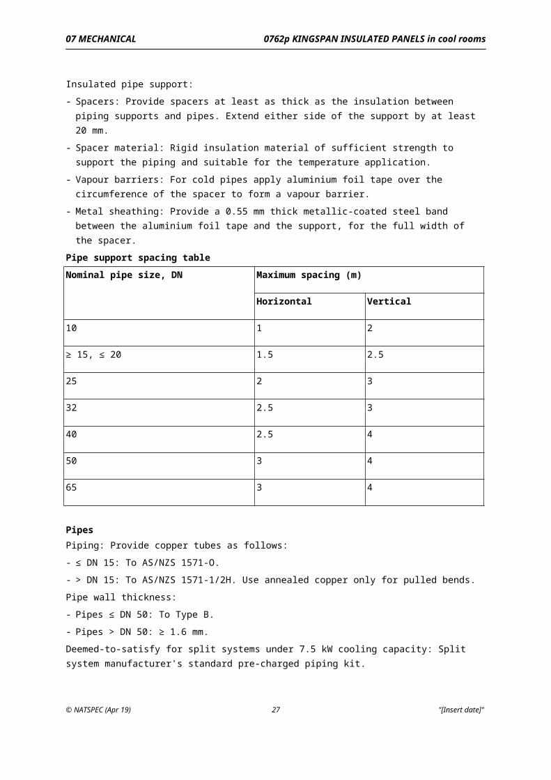
Pipe support spacing tableNominal pipe size, DN Maximum spacing (m)
Horizontal Vertical
10 1 2
≥ 15, ≤ 20 1.5 2.5
25 2 3
32 2.5 3
40 2.5 4
50 3 4
65 3 4
PipesPiping: Provide copper tubes as follows:
- ≤ DN 15: To AS/NZS 1571-O.
- > DN 15: To AS/NZS 1571-1/2H. Use annealed copper only for pulled bends.
Pipe wall thickness:
- Pipes ≤ DN 50: To Type B.
- Pipes > DN 50: ≥ 1.6 mm.
© NATSPEC (Apr 19) 20 "[Insert date]"
07 MECHANICAL 0762p KINGSPAN INSULATED PANELS in cool rooms
Deemed-to-satisfy for split systems under 7.5 kW cooling capacity: Split system manufacturer's standard pre-charged piping kit.
BendsPulled bends: Form bends without flattening or wrinkling with an inside radius not less than 3 pipe diameters using the correct tool size for the pipe diameter.
Pipe fittingsCopper alloy fittings: To AS 3688, dezincification resistant, welded, brazed or compression type only.
Preformed fittings: Preformed refrigerant capillary line tees, bushes, couplings and elbows. Wherever possible make reductions at elbows, tees, line devices or equipment connections with reducing fittings, otherwise provide reducing bushes or reducing couplings.
Compression fittings: Flareless twin ferrule, torque free, mechanical grip fittings which can be gauged using a precision ground and hardened metal gap inspection gauge. Provide frost proof flare nuts.
Screwed joints: Use only if equipment items are not available with flare, flanged or brazed capillary connections.
Brazed jointsGeneral: Provide preformed capillary fittings or form capillary unions by expanding one pipe end. Prevent flux and brazing alloy from entering pipes. Use dry nitrogen to purge air from pipes before brazing. During brazing, maintain a flow of dry nitrogen through pipes to prevent oxidation.
Brazing alloy: To AS/NZS 1167.1 Table 2 alloy B4 not less than 15% silver content.
Brazing alloy for jointing dissimilar metals: To AS/NZS 1167.1 Table 1 alloy A18 or an alloy with an equivalent silver content (≥ 34%) and impurity levels.
SleevesGeneral: Provide copper pipe sleeves where pipes pass through building elements to BUILDING PENETRATIONS, Sleeves in 0171 General requirements. Insulate the space between the pipe and sleeves.
ValvesGeneral: Provide valves to AS/NZS 5149.2. Make provision for charging and withdrawal of refrigerant. If a gauge is not permanently connected (for example commissioning connections), seal the outlet of the isolating valve with a flared seal cap nut.
Valve typesExpansion valves: To maintain correct superheat over the operating range.
Line valves: Packed and capped line globe valves: Back seating valves with renewable nylon or PTFE seats, packed spindle and removable gland cap. Incorporate mounting feet integral with valve body with adequate fixing holes.
Service valves: Backseating type with gasketed cap.
Solenoid line valves: Solenoid coil and valve parts replaceable without disturbing valve body or refrigerant piping.
Piping protectionExtent: Protect refrigeration piping exposed to view, weather or potential damage with piping covers fabricated from 0.6 mm thick prefinished metallic coated steel.
Section: Folded hat sections to suit piping.
Weatherproofing: Weatherproof external joints and fixings with non-setting mastic.
3.13 CONDENSATE DRAINS
© NATSPEC (Apr 19) 21 "[Insert date]"
07 MECHANICAL 0762p KINGSPAN INSULATED PANELS in cool rooms
GeneralCondensate drains: Provide trapped drain lines with uniform and continuous fall to connect condensate trays to the nearest building drain point.
Material:
- Room operating temperature > 0°C: PVC-U
- Room operating temperature ≤ 0°C:
. Inside room: Copper.
. Outside room: PVC-U.
- All cool rooms in kitchens: Chrome plated copper.
Size: The greater of unit drain connection size and DN 20.
Pipe support spacing: To AS/NZS 3500.1 Table 5.6.4.
Sealing: Seal drain pipes where they penetrate casing.
Termination: Terminate drains to allow visual inspection of condensate flow.
Traps: To withstand more than 2 times fan static pressure. Construct from either:
- Transparent, kink resistant hose.
- PVC-U trap with removable caps and a visible air break.
Falls and drains: Check that the condensate tray falls conform to AS/NZS 3666.1 and in particular that trays and sumps are graded to the outlet to prevent moisture retention. Test drains by pouring a measured quantity of water into upstream end.
Trace heatingRoom operating temperature ≤ 2°C: Provide trace heating to condensate drain piping to prevent their contents from freezing.
Control: Integrate heater operation with defrost termination and fan delay thermostat.
3.14 REFRIGERATION PIPE INSULATION
MaterialGeneral: Insulate all refrigerant piping that may sweat. Apply insulation un-slit where possible. If slit, refix slit faces with adhesive applied to full area.
Thickness:
- Room operating temperature > 2°C:
. Suction line: 19 mm.
. Condensate line: Not required.
- Room operating temperature ≤ 2°C:
. Suction line: 38 mm (2 to 19 mm layers).
. Condensate line: 13 mm.
Type: Chemically blown closed cell nitrile rubber or polyethylene in tubular form.
Physical properties:
- Maximum thermal conductivity: 0.04 W/(m.K) at 0°C.
- Moisture absorption: Non-hygroscopic.
- Water vapour diffusion resistance µ: ≥ 5000 to EN 13469.
Joining: Use only an adhesive or jointing system supplied by the insulation manufacturer.
Timing: Leak test piping before insulating joints, fittings and valves.
© NATSPEC (Apr 19) 22 "[Insert date]"
07 MECHANICAL 0762p KINGSPAN INSULATED PANELS in cool rooms
Finish: Where exposed to sunlight or to view in occupied areas, provide 2 coats of tintable, water-based, rubberised, ultraviolet-resistant, flexible paint finish.
Penetrations through fire rated elements: If insulated pipe penetrates a fire-resistance rated element, provide a section of non-combustible, non-hygroscopic insulation for the thickness of the element and 150 mm each side.
Fire performanceFire hazard properties: Tested to AS/NZS 1530.3. Fire hazard indices as follows:
- Spread-of-Flame Index: 0.
- Smoke-Developed Index: ≤ 3.
3.15 EVACUATION OF REFRIGERANT GAS SYSTEMS
GeneralSystem evacuation: Dehydrate the refrigerant gas system before charging with the refrigerant gas.
Evacuation: Use a high-vacuum pump, capable of reducing the pressure in the system to less than 53 Pa (400 microns) connected to both high and low pressure sides of the system with valves open and controls connected. Measure the pressure with approved calibrated electronic or similar gauges.
Test time: Maintain vacuum for a period not less than 12 hours to verify the vacuum is stable.
3.16 ELECTRICAL GENERALLY
GeneralRequirement: Conform to 0781 Mechanical electrical.Conduits: Box type sealed internally.
Stand-off brackets: If conduits are exposed within the cool room or in food preparation areas, support on brackets to provide the clearances from adjacent surfaces to AS 4674 clause 3.2.9.
Control panel cabinetsConstruction: Provide control panels documented as follows:
- Metallic-coated steel: Construction to 0781 Mechanical electrical.- Proprietary: Proprietary IP65 polycarbonate enclosure with removable front cover retained by
quarter turn fasteners with front cover fasteners and wall fixing holes located outside the sealed space. In all other respects conform to 0781 Mechanical electrical.
3.17 BATTERY SUPPLY
GeneralRequirement: Provide a mains powered battery charger and battery to serve alarms and emergency lighting, independent of all other emergency power supply within the building.
BatteriesType: Provide maintenance free, sealed, lead acid type batteries 12 volt.
Battery capacity: 7 amp hour or sufficient to run all emergency lights for 2 hours, whichever is the greater.
Battery chargerType: Provide a battery charger suitable for continuous float charge use in conformance with the battery manufacturer's recommendations.
Charging current: 2.5 Amps maximum continuous current and a terminal voltage of 13.7 V d.c. Incorporate individual connections for battery and load output with a re-settable current overload protection device, with visual device incorporated in the charger.
© NATSPEC (Apr 19) 23 "[Insert date]"
07 MECHANICAL 0762p KINGSPAN INSULATED PANELS in cool rooms
InstallationMounting: Securely mount the charger and battery in a separate enclosure with hinged door, of the same construction as the Control Board, attached to and mounted below the Control Board. Provide a label on the door BATTERY AND CHARGER.
Connection: Polarise the connections from the charger to the battery and load or clearly mark to prevent reverse connection.
LabelBattery installation/replacement date: Attach a stamped metal tag to the battery indicating the installation date and advised replacement date to the battery manufacturer's recommendations.
3.18 LIGHTING
Service lightingCool rooms for food storage: To AS 4674.
Service lighting requirement: Provide at least one single 18 W service light fitting in each cool room.
LuminairesCool rooms for food storage: To AS 4674.
Type: Provide fluorescent luminaires specifically designed for use at both ambient temperature and the cool room operating temperature.
Diffuser: High impact acrylic or UV stabilised polycarbonate.
Protection: Provide luminaires to IP65. House the controlgear in a moisture proof moulded polycarbonate glass reinforced plastic (GRP) box. Seal all wiring entries.
Switching requirementsService lights: Provide a labelled ON/OFF control switch on the inside of the cool room adjacent to the door, to control the service light(s). Arrange so that the light cannot be switched off from outside the room.
Pilot light: Provide a pilot light on the outside of the cool room to indicate when the service lights are on.
3.19 EMERGENCY LIGHTING
GeneralLocation: Provide an emergency light within each cool room adjacent to the exit door, positioned to illuminate the emergency door release mechanism, alarm and emergency instructions.
Luminaire: Prismatic bulkhead type, fitted with a 10 watt 12 volt quartz halogen incandescent lamp, with non-corrosive body and hinged one piece polycarbonate cover, separated by a neoprene gasket. The fitting to be completely waterproof and suitable for use at both the cool room operating temperature and ambient temperature.
Switching: Power the emergency light from the emergency lighting battery supply, to operate automatically in the event of mains power supply failure to the cool room lighting circuit.
LuminairesVisual indicator lights: Provide a red indicator, readily visible when the luminaire is in its operating location, which indicates that the battery is being charged.
Inverter system: Provide protection of the inverter system against damage in the event of failure, removal or replacement of the lamp, while in normal operation.
Local test switches: Provide a momentary action test switch, accessible from below the ceiling, on each luminaire to temporarily disconnect the mains supply and connect the battery to the lamp.
© NATSPEC (Apr 19) 24 "[Insert date]"
07 MECHANICAL 0762p KINGSPAN INSULATED PANELS in cool rooms
Common test switches: Provide a common test switch on the distribution board which disconnects main supply to the luminaires and tests for discharge performance, after testing, this switch must automatically revert to normal operating mode.
BatteriesLocation: Locate batteries outside the cool room.
Type: Lead acid or nickel cadmium batteries capable of operating each lamp at its rated output continuously at least 2 hours during final commissioning, pre-practical completion tests and 1.5 hours during subsequent tests.
Battery life: At least 3 years when operating under normal conditions at an ambient temperature of 25ºC and subjected to charging and discharging at 6 monthly intervals.
Marking: Indelibly mark each battery with its date of manufacture.
Power supplyGeneral: Provide an unswitched active supply to each luminaire and exit sign.
3.20 PERSONNEL SAFETY ALARM
AlarmRequirement: Provide each cool room with a personnel safety alarm consisting of an emergency pushbutton switch and an audible alarm and indicator light in all cool rooms as follows:
- Emergency switch: Mechanical illuminated latching mushroom type located in cool room adjacent to the exit door and suitable for use at the cool room operating temperature.
- Audible alarm: Bell or siren type located above (outside) the cool room door. Alarm to be silenced by reversing the emergency switch.
- Indicator light: Flashing red, ≥ 50 mm diameter, located outside and above the cool room door.
- Label the light: PERSON TRAPPED IN COOL ROOM.
3.21 CONTROLS GENERALLY
Control moduleGeneral: Provide a microprocessor-based electronic control module, to monitor and control each cool room and its refrigeration system. Locate each control module outside the cool room it serves. Provide the following functions:
- Control the cool room temperature.
- Adjustable set point and control differential.
- Measure, log (hourly) and display the cool room temperature.
- Display highest and lowest room temperature logs for period.
- Sensor calibration.
- High room temperature alarm.
- Automatic duty/standby change over for cool rooms with duty/standby systems.
- Alarm outputs.
- Phase failure relay.
- Automatic defrost cycle control.
- Defrost cycle sequencing to prevent simultaneous defrost if the cool room has multiple refrigeration systems.
- Separate fuses for each evaporator.
- Manual defrost initiate and termination.
© NATSPEC (Apr 19) 25 "[Insert date]"
07 MECHANICAL 0762p KINGSPAN INSULATED PANELS in cool rooms
- Display time to next defrost and time from last defrost.
- Anti-short cycle adjustable timer limits compressor starts per hour.
- Self test function.
- Memory retention in the event of power failure.
Evaporator shutdown: Provide a labelled switch to LIGHTING, Switching requirements matching the light switch for each cool room to shut down the evaporator fans and refrigerant solenoid valves.
Temperature controlControl accuracy: Maintain the required room temperature within ± 0.5 K of set point.
Evaporator fans: To run continuously during normal (non defrost) operation.
Defrost cycleRoom operating temperature > 0°C: Provide a defrost cycle controlled by the electronic control module, with time initiation and evaporator temperature termination. Run evaporative fans continuously during defrost.
Room operating temperature ≤ 0°C: Provide a defrost cycle controlled by the electronic control module, time initiated and evaporator temperature terminated. De-energise the evaporator fan during the defrost cycle and delay it from restarting on termination of the defrost cycle until the evaporator reaches operating temperature.
Installation protectionRequirement: Provide the following:
- Motor thermal overload.
- Manually reset low and high pressure cutouts.
- Separate fuses for multiple evaporator fans.
BMS interfaceBMS points: Provide the alarm and monitoring points to interface with the BMS.
Connection: Provide voltage-free contacts wired to a dedicated terminal strip in the respective cool room switchboard.
Independent operation: Arrange the interface so that failure or fault in the BMS does not render the cool room installation inoperative in any way.
3.22 CONTROLS FOR COOL ROOMS WITH DROP IN AND SLIDE IN SINGLE PACKAGED REFRIGERATION UNITS
GeneralControl: If a drop-in or slide-in packaged refrigeration unit is documented for the cool room, provide the unit fully factory wired and complete with all refrigeration controls, other controls and safeties.
Thermometer: Provide a 100 mm dial thermometer to each cool room.
Defrost: Incorporate electric defrost heaters in refrigeration units. Defrost to be time initiated, pressure or temperature terminated, with fail-safe override and evaporator fan delay.
3.23 PAINTING AND LABELLING
GeneralRequirement: Conform to 0171 General requirements.
StandardsRefrigeration systems: To AS/NZS 5149.2.
Safety signs: To AS 1319.
© NATSPEC (Apr 19) 26 "[Insert date]"
07 MECHANICAL 0762p KINGSPAN INSULATED PANELS in cool rooms
Emergency instructionsNotice: Provide a notice located within the cool room adjacent to the door indicating the locations of the personnel safety alarm switch and door release mechanism with instructions on how to activate the alarm and operate the door release mechanism.
Construction: Photo luminescent type with lettering at least 15mm high. Screw fix to the cool room wall panel. Provide a photo luminescent exit sign above the cool room door.
Photo luminescent sign output: ≥ 2 mcd/m2, 60 minutes after light source is removed.
LabelsGeneral: Provide labels for the following:
- Controls.
- Switches.
- Switchboard components.
- Indicator lights.
- Alarms.
- Each cool room door.
- Control boards.
- Condensing units.
3.24 WARRANTIES
GeneralRequirement: On completion and when inspected by KINGSPAN, provide KINGSPAN warranty.
Period: Provide KINGSPAN warranties as follows:
- 10 years for thermal performance.
- 10 years for structural performance.
- 10 years for coating performance.
4 SELECTIONS
4.1 COOL ROOMS
Cool room scheduleProperty Cool room 1 Cool room 2 Cool room 3
Room function
KINGSPAN panel type
Ambient humidity
Panel width (mm)
Panel length (m)
External Sheet: Thickness (mm)
© NATSPEC (Apr 19) 27 "[Insert date]"
07 MECHANICAL 0762p KINGSPAN INSULATED PANELS in cool rooms
Property Cool room 1 Cool room 2 Cool room 3
External sheet: Profile
External sheet: Finish
External sheet: Colour
Internal sheet: Thickness (mm)
Internal sheet: Profile
Internal sheet: Finish
Internal sheet: Colour
Core thickness (mm):
R-Value
Fire-resistance level (FRL)
Room internal dimensions: Length ( mm)
Room internal dimensions: Width ( mm)
Room internal dimensions: Height ( mm)
Room operating temperature (°C)
Room operating temperature tolerance (°C)
Ambient conditions: Dry bulb (°C)
Ambient conditions: Wet bulb (°C)
Air cooled condenser: Air entering temperature
© NATSPEC (Apr 19) 28 "[Insert date]"
07 MECHANICAL 0762p KINGSPAN INSULATED PANELS in cool rooms
Property Cool room 1 Cool room 2 Cool room 3
(°C)
Water cooled condenser: Water entering temperature (°C)
Water cooled condenser: Water leaving temperature (°C)
Refrigeration plant capacity at above conditions (kW(r))
Refrigeration plant operating hours per day
Wall panel facing profile: Inside
Wall panel facing profile: Outside
Ceiling panel facing profile: Inside
Ceiling panel facing profile: Outside
Panel protection: Internal wall protection
Panel protection: Door protection
Floor: Floor wearing surface type
Floor: Concrete wearing surface finish
Floor: Tanking option
Main door: Door type
Main door: Door clear opening (width ( mm) x
© NATSPEC (Apr 19) 29 "[Insert date]"
07 MECHANICAL 0762p KINGSPAN INSULATED PANELS in cool rooms
Property Cool room 1 Cool room 2 Cool room 3
height ( mm))
Main door: Viewing panel size (width ( mm) x height ( mm))
Emergency access doors: Number required
Emergency access doors: Door action
Emergency access doors: Door clear opening (width ( mm) x height ( mm))
Refrigeration plant: Type
Refrigeration plant: Acceptable refrigerants
Refrigeration plant: Compressor type
Refrigeration plant: Compressor drive
Refrigeration plant: Suction and discharge pressure gauges
Refrigeration plant: Condensing unit enclosure
Refrigeration plant: Condenser fan motor
Refrigeration plant: Evaporator fan motor
Control panels: Enclosure material
Service lighting: Number of luminaires
© NATSPEC (Apr 19) 30 "[Insert date]"
07 MECHANICAL 0762p KINGSPAN INSULATED PANELS in cool rooms
Property Cool room 1 Cool room 2 Cool room 3
Control options: Phase failure relay
Control options: Condensing unit fault indication
Control options: Lamp test switch
Remote alarms: Refrigeration plant fault
Remote alarms: Room over temperature
4.2 BMS INTERFACE
Cool room BMS points scheduleEquipment item and point description
Point type Scheduled Trend log Alarm Include in graphic
Legend
AI: Analog input (hardware point).
AO: Analog output (hardware point).
DI: Digital input (hardware point).
DO: Digital output (hardware point).
4.3 COOL ROOM ACCESSORIES
Shelving scheduleProperty Cool room 1 Cool room 2 Cool room 3
Number of shelving modules
© NATSPEC (Apr 19) 31 "[Insert date]"
07 MECHANICAL 0762p KINGSPAN INSULATED PANELS in cool rooms
Property Cool room 1 Cool room 2 Cool room 3
Size of modules (width x depth x height) (mm)
Number of shelves per module
Post and frame material
Shelf material
Number of dunnage shelves
Size of dunnage selves (width x depth) (mm)
Dunnage shelf material
© NATSPEC (Apr 19) 32 "[Insert date]"