080101-8 conveyordw io 091608 - stero warewashing€¦ · sct-xx-csa sct-xxs sct-xxs-cs sct-xxs-csa...
TRANSCRIPT

CONVEYOR TYPEDISHWASHERS
MODELS
SCTSCT-XX-CSSCT-XX-CSASCT-XXSSCT-XXS-CSSCT-XXS-CSASCT-XXSCSTW-XX
INSTALLATION &OPERATION MANUAL
STERO, A DIVISION OF ILLINOIS TOOL WORKS INC.WWW.STERO.COM
3200 LAKEVILLE HWY.PETALUMA, CA 94954
For additional information on Stero or to locate an authorized parts andservice provider in your area, visit our website at www.stero.com.
SCX-XSCX-X-XSCX-X-X-XSCX-X-X-X-X-XER-XXER-XX-XXER-XXSER-XXSC

— 2 —
Conveyor Type Dishwashers
IMPORTANT FOR YOUR SAFETYONLY QUALIFIED PERSONNEL SHOULD PERFORM THE INITIAL FIELDSTARTUP AND ADJUSTMENTS OF THE EQUIPMENT COVERED BY THIS MANUAL.
READ THIS MANUAL THOROUGHLY BEFORE OPERATING, INSTALLING ORPERFORMING MAINTENANCE ON THE EQUIPMENT.
Improper installation, adjustment, alteration, service or maintenance cancause property damage, injury or death.
POST IN A PROMINENT LOCATION THE INSTRUCTIONS TO BE FOLLOWED INTHE EVENT THE SMELL OF GAS IS DETECTED. THIS INFORMATION CAN BE
OBTAINED FROM THE LOCAL GAS SUPPLIER.
IMPORTANTIN THE EVENT A GAS ODOR IS DETECTED, SHUT DOWN UNITS AT MAINSHUTOFF VALVE AND CONTACT THE LOCAL GAS COMPANY OR GASSUPPLIER FOR SERVICE.
FOR YOUR SAFETYDo not store or use gasoline or other flammable vapors or liquids in the vicinity ofthis or any other appliance.
SHUT OFF THE GAS BEFORE SERVICING THE UNIT.
All gas joints disturbed during servicing must be checked for leaks. Checkwith a soap and water solution (bubbles). Do not use an open flame.
SHUT OFF THE STEAM BEFORE SERVICING THE UNIT.
Disconnect the electrical power to the machine and follow Lockout/Tagoutprocedures. There may be multiple circuits. Be sure all circuits are disconnected.
Electrical and grounding connections must comply with the applicableportions of the National Electric Code and/or other local electrical codes.
UL73 grounding instructions: This appliance must be connected to agrounded, metal, permanent wiring system; or an equipment-grounding conductor must berun with the circuit conductors and connected to the equipment-grounding terminal or leadon the appliance.
IN THE EVENT OF A POWER FAILURE,DO NOT ATTEMPT TO OPERATE THIS DEVICE.

— 3 —
Conveyor Type Dishwashers
TABLE OF CONTENTSGENERAL ....................................................................................................................................5
INTRODUCTION .........................................................................................................................5LOCATION OF DATA PLATE.....................................................................................................5TOOLS ....................................................................................................................................6
Standard ................................................................................................................................6Special ...................................................................................................................................6
PRE-INSTALLATION...................................................................................................................6Utility Connection Requirements ..........................................................................................6
INSTALLATION..................................................................................................................................7CODES AND STANDARDS .......................................................................................................7UNCRATING ................................................................................................................................7LEVELING7LOAD/UNLOAD TABLE ATTACHMENT ...................................................................................8TABLE LIMIT SWITCH INSTALLATION (OPTIONAL) ...............................................................9
Table Limit Switch Electrical Connection ............................................................................9CURTAIN INSTALLATION ....................................................................................................... 10VENTILATION DUCT CONNECTION (If required) ................................................................. 10
Gas-Heated Dishwashers ................................................................................................. 10Steam or Electric-Heated Dishwashers ........................................................................... 11
ELECTRICAL CONNECTIONS ............................................................................................... 11UTILITY CONNECTIONS ......................................................................................................... 12
PLUMBING CONNECTIONS ............................................................................................. 12Water Supply Connections .......................................................................................... 12Drain Connections ....................................................................................................... 12Steam Connections ..................................................................................................... 12
GAS CONNECTIONS ........................................................................................................ 13Gas Lockout/Tagout Procedures ................................................................................ 13Gas Supply Connection ................................................................................................13Gas Leak Test .............................................................................................................. 13
ELECTRICAL CONNECTIONS ......................................................................................... 13Electrical Lockout/Tagout Procedures........................................................................ 14Main Electrical Supply Connection .............................................................................. 14
Detergent & Rinse Aid Supply Connections ..................................................................... 14OPERATION ................................................................................................................................. 15
OPERATING CONTROLS LOCATION................................................................................... 15Push Button Control Panel ................................................................................................ 15LCD Control Panel ............................................................................................................. 15

— 4 —
Conveyor Type Dishwashers
Temperature Gauges ......................................................................................................... 15OPERATING CONTROLS FUNCTION................................................................................... 16
PUSH BUTTON CONTROL PANEL ................................................................................. 16LCD CONTROL PANEL .................................................................................................... 16
RUN CYCLE ............................................................................................................................. 17Push Button Control Panel ................................................................................................ 17LCD Control Panel ............................................................................................................. 18
SHUTDOWN ............................................................................................................................ 19Daily Shutdown................................................................................................................... 19Extended Shutdown ........................................................................................................... 19
MAINTENANCE .............................................................................................................................. 20PARTS REMOVAL ................................................................................................................... 20
Scrapper Spray Manifold Removal .................................................................................... 20Tree-Type Spray Manifold Removal .................................................................................. 20Curtain Removal ................................................................................................................ 21Strainer Pans Removal...................................................................................................... 21
CLEANING ................................................................................................................................ 22Interior ................................................................................................................................. 22Spray Manifolds (Tree-Type and Scrapper) ..................................................................... 22Curtains .............................................................................................................................. 22Exterior ................................................................................................................................ 23
STAINLESS STEEL CARE...................................................................................................... 23Cleaning .............................................................................................................................. 23Preserving & Restoring...................................................................................................... 23
DELIMING .................................................................................................................................. 23DISPLAY MESSAGES ................................................................................................................... 24TROUBLESHOOTING................................................................................................................... 25PRODUCT SUPPORT AND SERVICE ........................................................................................ 26STERO WARRANTY ..................................................................................................................... 27CALIFORNIA SAFE DRINKING WATER ANDTOXIC ENFORCEMENT ACT OF 1986, (PROP. 65) .................................................................. 28SERVICE AND INSTALLATION INSPECTION REPORT ............................................................. 31

— 5 —
Conveyor Type Dishwashers
GENERALINTRODUCTION
Every Stero product is built with the highestquality components and innovative featuresthat have established Stero’s reputation asthe food service industry’s warewashingauthority.
Stero Rack Conveyor washers move rackeddishes by a pawl. Pawl action uses a singlebar to pull the racks through the dishwasher.The dish rack is conveyed through a spraypattern directed from upper and lowerstationary spray arms at a prescribed GPMflow rate. After the rack has passed throughthe wash spray, it moves on to activate thefresh-water final rinse.
Automatic warewashers contain heaters thatmaintain the proper water temperature in thedishwasher tanks. These heaters useelectricity, steam or gas. As a general rule,heaters maintain a tank temperature of 160ºF(71ºC) to ensure sanitation. Hot watersanitizing warewashing dishwashers use abooster heater to raise the incoming, generalpurpose hot water to at least 180ºF (82ºC) forthe final sanitizing rinse.
The NSF requires an established amount ofheat content to ensure sanitation. The waterpressure for this cycle must be 20 PSI.
LOCATION OF DATA PLATE
The data plate (Figure 1) is located either onthe front or on the side of the Main ElectricalControl Panel. This data plate containsimportant information, including thedishwasher model and serial number.
Always have the model and serial numberbefore calling for parts or service.
Figure 1: Data Plate

— 6 —
Conveyor Type Dishwashers
TOOLS
Standard
• Standard set of hand tools
• Gas leak detection equipment (gas-powered equipment installation only)
• Gas pressure Manometer (gas-poweredequipment installation only)
Special
• NSF approved silicone sealant
• Pipe joint compound
• Torx security screwdriver (correctionalfacility equipment only)
• Bubble level
• Sheet metal modification tools (dishtable & Table Limit switch installation)
PRE-INSTALLATION
Utility Connection Requirements
Utility connections must be present and readyfor hookup to the dishwasher. All utility suppliesmust comply with the electrical informationlabels, with the data plate, and with allapplicable local and national codes.
Electrical leads, water supply line(s), drainline, gas and steam supply and condensatereturn lines (if so equipped) must be present.The water supply must match the pressureand temperature specified on the serial dataplate. The steam or gas supply (if so equipped)must match the pressure and volume specifiedon the data plate.
For units using a detergent & rinse aiddispensing system, appropriate dispensersor containers should be installed and ready forconnection to the dishwasher.

— 7 —
Conveyor Type Dishwashers
CODES AND STANDARDS
In the United States, the dishwasher must beinstalled in accordance with:
• State and local codes
• National Fuel Gas Code, ANSI-Z83.21,Commercial Dishwashing Machines(latest edition)
• National Fuel Gas Code, ANSI Z223.1(latest edition)
• National Fire Protection Association,NFPA 54 (latest edition)
• Underwriters Laboratories standard UL921, Commercial Dishwashers (latestedition)
• National Electrical Code NEC/NFPA 70(latest edition)
In Canada:
• Local codes
• Canadian Electrical Code Part 1 CSAC22.1(latest edition)
• CAN/CSA-C22.2 Number 168,Commercial Dishwashing Machines(latest edition)
• CAN/CSA B149.1, Natural Gas andPropane Installation (latest edition)
UNCRATING
NOTE: As the equipment is unpacked, checkthat all components shown on the shippinginvoice are present. Be sure to check forshipping damage. If shipping damage ispresent, contact Stero Customer Service at1-800-762-7600 and provide customer details,dishwasher serial number and the extent ofdamage. Stero will file a freight claim basedon this information.
INSTALLATION Unless authorized by
Stero Customer Service or its authorizedagent, a damaged unit should not beinstalled or operated.
To uncrate the dishwasher, perform thefollowing:
1. Remove all shipping and packagingmaterial from the dishwasher, includingsupports and wrappings. Leave theshipping skid in place to allow for easiermovement to the installation location.
2. Check for shipping damage as describedabove.
The pallet should not be removeduntil the dishwasher has been moved to itsinstallation area. Damage can occur fromimproper lifting and uneven weight distribution.
Do not attempt to slide the dishwasheron its feet. This can bend the legs.
3. Move the dishwasher to the installationarea and remove the skid. Use caution toavoid damaging the dishwasher or itscomponents.
LEVELING
For proper operation, the dishwasher must belevel. To level the dishwasher:
1. Using a bubble level, check that thedishwasher is level from both front to backand left to right.
2. Screw the feet in or out until unit is levelboth front to back and left to right.
— 8 —
Conveyor Type Dishwashers
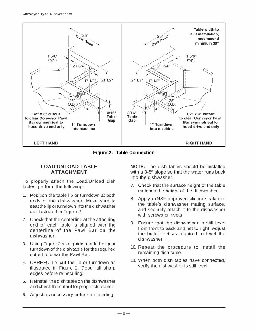
LOAD/UNLOAD TABLEATTACHMENT
To properly attach the Load/Unload dishtables, perform the following:
1. Position the table lip or turndown at bothends of the dishwasher. Make sure toseat the lip or turndown into the dishwasheras illustrated in Figure 2.
2. Check that the centerline at the attachingend of each table is aligned with thecenterline of the Pawl Bar on thedishwasher.
3. Using Figure 2 as a guide, mark the lip orturndown of the dish table for the requiredcutout to clear the Pawl Bar.
4. CAREFULLY cut the lip or turndown asillustrated in Figure 2. Debur all sharpedges before reinstalling.
5. Reinstall the dish table on the dishwasherand check the cutout for proper clearance.
6. Adjust as necessary before proceeding.
Figure 2: Table Connection
NOTE: The dish tables should be installedwith a 3-5º slope so that the water runs backinto the dishwasher.
7. Check that the surface height of the tablematches the height of the dishwasher.
8. Apply an NSF-approved silicone sealant tothe table’s dishwasher mating surface,and securely attach it to the dishwasherwith screws or rivets.
9. Ensure that the dishwasher is still levelfrom front to back and left to right. Adjustthe bullet feet as required to level thedishwasher.
10. Repeat the procedure to install theremaining dish table.
11. When both dish tables have connected,verify the dishwasher is still level.

— 9 —
Conveyor Type Dishwashers
Figure 3: Table Limit Switch Installation
TABLE LIMIT SWITCH INSTALLATION(OPTIONAL)
If the dishwasher has an optional Table LimitSwitch, connect the Table Limit Switch to theend of the unload dish table as follows:
1. Mark the centerline of the unload table endouter surface.
2. Mark the Table Limit switch bar horizontalcenterline approximately 1-3/8" above thedish table surface. This will allow properclearance of the Table Limit switchActuator lever.
3. Using Figure 3 as reference, mark and cutoutthe 1-1/4" x 6" Table Limit switch accessslot. Be sure to debur all sharp edges.
4. When the access slot has been created,align the Table Limit switch centerline withthe dish table centerline. Ensure the TableLimit switch bar has sufficient clearanceto actuate approximately 3/8" forward andbackward travel.
5. When proper clearance has been verified,mark the underside of the dish table for theTable Limit switch mount fasteners.
6. Weld studs or weld the switch to the bottomof the table.
7. Place the Table Limit switch in position tomake sure the Table Limit switch mountholes line up with the holes in the dishtable. Adjust as required.
8. Verify the Table Limit switch actuatesforward and backward properly withoutany obstruction. Correct as required.
Table Limit Switch Electrical Connection
After installing the Table Limit Switch to thedish table, connect the electrical connectionsas follows:
1. Perform the Lockout/Tagout procedures.
2. Locate the electrical junction box on theunload side of the dishwasher.

— 10 —
Conveyor Type Dishwashers
3. Remove the two (2) screws securing thejunction box cover. Retain for reinstallation.
4. Route the wires from the Table Limit Switchthrough the sealtite connector on thejunction box.
5. Remove the jumper wire and connect thetwo (2) electrical wires from the Table LimitSwitch to the two (2) terminals on the terminalblock located inside the junction box.
6. Reinstall the junction box cover removedin step 3.
Figure 4: Table Limit SwitchElectrical Connection
CURTAIN INSTALLATION
Multi–flap curtains are used throughout thedishwasher to keep moisture inside and reducethe potential of hot water injury. The curtainconfigurations vary by model and size. Refer tothe curtain placement decals located on thefront of the main dishwasher hood for the exactcurtain number and placement. Installationprocedures are the same for all curtains.
1. Starting with the long, middle curtain, reachinside the main dishwasher compartmentand locate the middle curtain rod holder.
2. Place one end of the curtain rod into itsholder.
3. Place the other end of the curtain rod intoits holder.
4. Repeat the procedure for the remainingcurtains.
LongCurtain
ShortCurtain
Figure 5: Curtain Rod Holder
VENTILATION DUCT CONNECTION(IF REQUIRED)
For units that do not require ventilation ductconnections, proceed to the UTILITYCONNECTIONS section.
Gas-Heated Dishwashers
NOTE: Infrared gas tank heat-equippeddishwashers are supplied with a stainlesssteel exhaust system, which terminatesapproximately 5.5" above the hood in the rearof the dishwasher. Do not make a sealedconnection to the dishwasher exhaust stack.Refer to Figure 6 for gas dishwasher ventinginstallation requirements.

— 11 —
Conveyor Type Dishwashers
Air Gap
CondensateVenting
Figure 6: Recommended Gas Venting
Steam or Electric-Heated Dishwashers
For all other units requiring ventilation ductconnections, proceed as follows:
1. Check that the ventilation ducts are correctlypositioned above the dishwasher vents.
2. Refer to the Stero Engineering Drawing forthe dishwasher ventilation requirements.This drawing is located in the Main ElectricalControl Panel.
NOTE: Ducts should fit inside the dishwashervents but not interfere with the operation of thedampers.
3. Install the venti lation ducts to thedishwasher vents per the dishwasher ductrequirements and per local and statecodes.
4. Seal the duct connection joint with siliconesealant.
ELECTRICAL CONNECTIONS
The exhaust fan is connected to an electricalbox located on the back of the Main ElectricalControl Panel, labeled as FAN CONTACTORENCLOSED (Figure 7). Connect the electricalconnections as follows:
1. Remove the two (2) screws securing theFan Contactor cover plate. Retain forreinstallation.
2. Remove and discard the 1/2" neopreneplug from the hole in the top of the FanContactor box.
3. Install a 1/2" sealtite connector to theexposed hole in the top of the FanContactor box.
4. Route the incoming electrical wires throughthe sealtite connector.
5. Connect the incoming fan electrical wiresto the fan terminal block.
6. Reinstall the cover screws removed fromstep 1.
Make exhaust fanconnection here.
Remove plug and routeexhaust fan wires through here.
Figure 7: Exhaust FanElectrical Connection

— 12 —
Conveyor Type Dishwashers
UTILITY CONNECTIONS
PLUMBING CONNECTIONS
Water Supply Connections
Before connecting the watersupply, it must be purged to remove anycontaminates from the line.
NOTE: Ensure that the line strainer is installedso that iron or other metal particles cannotcontaminate the dishwasher.
Refer to the Stero Engineering Drawing toconnect the water supply to the dishwasherconnection(s) as indicated by the connectionlabels attached to the connection points.Proceed as follows:
1. Locate the water supply connection(s) aslabeled on the dishwasher.
2. Check the incoming water temperature.
3. Connect the customer-supplied waterline(s) to the appropriate connection(s).
NOTE: The dishwasher requires a pressureof 20 psi at the Final Rinse for correct operation(Figure 8). It may be necessary to increasethe pressure (with a booster pump) ordecrease the pressure (with a pressurereducing valve).
4. Check the incoming water pressure at theFinal Rinse Pressure Gauge.
Figure 8: Final Rinse Pressure
Drain Connections
NOTE: Make as many clean outs as possiblein the drain line, using tees with pipe plugs ineach tee instead of elbows, to allow the linesto be cleaned out periodically.
Refer to the Stero Engineering Drawing forthe dishwasher drain requirements.
NOTE: In some cases, a grease trap must befitted into the waste water line. If a grease trapis required for installation, check that it ispresent.
Install the Waste Drain per local and statecodes.
Steam Connections
NOTE: Before connecting the steam supply,it must be purged to remove any contaminatesfrom the line.
Refer to the Stero Engineering Drawing toconnect the steam supply and condensatereturn to the dishwasher connection(s)requirements as indicated by the connectionlabels attached to the dishwasher connectionpoints. Proceed as follows:
NOTE: Condensate return should be gravityfed back to the boiler. A return with an upwardslope will require individual condensationremoval systems.
1. Check that the incoming steam pressureis of sufficient pressure to meet thedishwasher pressure requirements perthe Stero Engineering Drawing.
2. Check that the pipe size is equal to orgreater than the dishwasher than thedishwasher requirements per the SteroEngineering Drawing.
3. When the correct pressure and volumehave been verified, connect the customer-supplied steam line(s) to the dishwashersteam connection(s) as indicated by thelabels attached to the dishwasherconnection(s).

— 13 —
Conveyor Type Dishwashers
GAS CONNECTIONS
All gas joints disturbedduring servicing must be checked forleaks. Do not use an open flame. Use ahazardous gas tester or a soap and watersolution (Bubbles indicate a gas leak).
Do not operate a gas-fueled appliance if a gas leak is present.
Gas Lockout/Tagout Procedures
The Lockout/Tagout procedure is used to protectpersonnel working on a gas appliance. Beforeperforming any maintenance or service thatrequires gas disconnections, follow these steps:
1. Locate the gas valve or inlet.
2. Place the valve in the OFF position.
3. Place a tag on the valve indicating thatservice is being performed on equipmentand the gas must remain off until serviceis complete.
4. Place a locking device on the gas valve orinlet, preventing connection until the lockis removed.
5. On the appliance, make sure all flamesources are extinguished and/or removed.
6. Bleed residual gas from the appliance inletline and allow time for the gas to dissipatebefore beginning service on the appliance.
Gas Supply Connection
NOTE: Before connecting the gas supply, itmust be purged to remove any contaminatesfrom the line.
Refer to the Stero Engineering Drawing toconnect the gas supply to the dishwasherconnection(s) as indicated by the labelsattached to the dishwasher connection(s)points. Proceed as follows:
1. Check that the volume of gas delivered issufficient for proper operation. Refer to theData plate and chart below for the dishwasherincoming gas pressure requirement.
GAS TYPE REQUIRED W.C.
Natural Gas 4+"
Liquid propane (LP) 9+"
2. Connect the customer-supplied gas lineto the dishwasher gas connection(s).
3. Perform the GAS LEAK TEST procedure.
Gas Leak Test
After completing service on any natural gasappliance, all gas joints disturbed during servicemust be checked for leaks. DO NOT USE ANOPEN FLAME. Use a hazardous gas tester oruse a soap and water solution as follows:
1. Apply a soap and water solution to gasjoint and check for bubbles.
2. If bubbles are present, the joint is leakingand must be repaired before using theappliance.
ELECTRICAL CONNECTIONS
Electrical connectionsshould be performed only by a certifiedprofessional.
Electrical and groundingconnections must comply with theapplicable portions of the National ElectricCode and/or other local electrical codes.
UL73 groundinginstructions: This appliance must beconnected to a grounded, metal,permanent wiring system; or anequipment-grounding conductor must berun with the circuit conductors andconnected to the equipment-groundingterminal or lead on the appliance.
Disconnect the electricalpower to the machine and follow Lockout/Tagout procedures.

— 14 —
Conveyor Type Dishwashers
Electrical Lockout/Tagout Procedures
Lockout/Tagout procedures are used toprotect personnel working on an electricalappliance. Perform the following steps whenperforming any type of maintenance or serviceon an electrically operated appliance.
1. Lockout the supply circuit breaker to thedishwasher.
2. Place a lock or other device on electricalbox cover to prevent someone from placingcircuit breaker ON.
3. Place a tag on electrical box cover toindicate that unit has been disconnectedfor service and power should not berestored unti l tag is removed bymaintenance personnel.
Main Electrical Supply Connection
Refer to the Stero Engineering Drawing andwiring diagram located inside the MainElectrical Control Panel for the dishwasherelectrical supply requirements.
To connect the main electrical supply, proceedas follows:
1. Perform the ELECTRICAL LOCKOUT/TAGOUT procedures.
NOTE: Amperage and minimum supply wirespecifications are shown on the wiring diagramlocated in the Main Electrical Control Panel.
2. Check that the incoming power leads areof sufficient rating for the dishwashercurrent draw.
3. Using the Stero Engineering Drawing andwiring diagram for reference, install thepower lines to the incoming powerterminals.
4. Connect the ground wire to the groundterminal marked GRD.
Figure 9: Main Electrical Connection
DETERGENT & RINSE AIDSUPPLY CONNECTIONS
Once the dishwasher has been installed andall utility, electrical, plumbing and ventilationconnections have been made, connect thechemical supply connections to the junctionbox located on the rear or side of the MainElectrical Control Box.
Make detergent & rinse aidconnections here.
Figure 10: Detergent and Rinse AidElectrical Connection

— 15 —
Conveyor Type Dishwashers
OPERATION
OPERATING CONTROLS LOCATION
The operating controls for the dishwasher arelocated in a stainless steel Main ElectricalControl Panel, which either is on the front ofor mounted on top of the dishwasher. Sterooffers two different types of dishwashercontrols. The two types of controls are:
• Push Button Control Panel
• LCD Control Panel
Push Button Control Panel
The Push Button Control Panel consists ofthe following controls, which are explained inthe OPERATING CONTROLS FUNCTIONsection of this manual:
RESET SAFETYOFF ON
FILL TANK HEAT START STOP
Figure 11: Push Button Control PanelOperating Controls Location
• SAFETY switch
• FILL button
• HEAT button
• START button
• STOP button
• Optional BOOSTER HEAT button
• Optional RESET button
LCD Control Panel
The LCD Control Panel consists of thefollowing controls, which are explained in theOPERATING CONTROLS FUNCTION sectionof this manual:
Figure 12: LCD Panel Operating ControlsLocation
• Power ON/OFF switch
• LCD Display screen
• START button
• STOP button
• FILL button
• HEAT button
• ALARM MUTE button
• BOOSTER HEAT button
Temperature Gauges
Also located on the front or top of thedishwasher are the temperature gauges. Thetemperature gauges provide a visual indication

— 16 —
Conveyor Type Dishwashers
for the water temperatures within each sectionof the dishwasher. The gauges are clearlylabeled and, depending on model and type,are for the following sections:
• Scrap tank water temperature
• Wash tank water temperature
• Rinse tank water temperature
• Final Rinse water temperature
Temperature Gauges
Figure 13: Temperature Gauge Locations
OPERATING CONTROLS FUNCTION
PUSH BUTTON CONTROL PANEL
SAFETY SwitchThe SAFETY switch energizes the dishwasherelectrical circuit when placed ON. The SAFETYswitch is located on the Main Electrical ControlPanel.
FILL ButtonThe FILL button energizes the Fill valves to fillthe tanks with water. The FILL button willremain illuminated when pressed, until all thetanks are full. The FILL button is located on theMain Electrical Control Panel.
HEAT ButtonThe HEAT button energizes the dishwasherheating circuit. The HEAT button is illuminatedwhen the tank heat is turned on and when thetanks are full. The HEAT button is located onthe Main Electrical Control Panel.
START ButtonThe START button energizes the electricalpumps and conveyor drive. The START buttonis located on the Main Electrical Control Panel.
STOP ButtonThe STOP button stops the conveyor andpumps. The STOP button is located on theMain Electrical Control Panel.
(Optional) BOOSTER HEAT ButtonThe BOOSTER HEAT button is only presenton units pre-wired with a steam Booster Heater.The BOOSTER HEAT button energizes thesteam Booster Heater control circuit. TheBOOSTER HEAT button, if preinstalled, islocated on the Main Electrical Control Panel.
RESET ButtonThe RESET button is only present on gas-heated dishwashers. The RESET button resetsthe electrical control circuit in the event of apower outage or interruption. The RESET buttonis located on the Main Electrical Control Panel.
LCD CONTROL PANEL
Power ON/OFF SwitchThe Power ON/OFF switch turns the ControlModule ON and OFF. The Power ON/OFF switchis located on the front of the dishwasher abovethe doors and near the Control Panel Keypad.
LCD Display Screen
The LCD Display screen displays the currentstatus or fault condition code for thedishwasher. The LCD Display screen islocated on the top section of the Control PanelKeypad.
START ButtonThe START button energizes the dishwasherRUN cycle. The START button is located onthe Control Panel Keypad.

— 17 —
Conveyor Type Dishwashers
STOP ButtonThe STOP button stops the conveyor andpumps. The STOP button is located on theControl Panel Keypad.
FILL ButtonThe FILL button energizes the water fill valves.The FILL button is located below the STARTbutton on the Control Panel Keypad.
HEAT ButtonThe HEAT button energizes the dishwasherheating circuit. The HEAT button is located onthe Control Panel Keypad.
ALARM MUTE ButtonThe ALARM MUTE button silences the audiblealarm when a fault condition occurs. TheALARM MUTE button is located on the ControlPanel Keypad.
BOOSTER HEAT ButtonThe BOOSTER HEAT button is only operationalfor dishwashers with an optional steamBooster Heater preinstalled. The BOOSTERHEAT button energizes the steam BoosterHeater circuit. The BOOSTER HEAT button islocated on the Control Panel Keypad.
RUN CYCLE
Push Button Control Panel
To complete a run cycle for dishwasher withpush button controls, perform the following:
Water temperature inside thedishwasher can reach 190ºF and causesevere burns.
1. Close all tank drain valves.
2. Make sure all Upper and Lower SprayManifolds are securely in place and all endcaps are tight.
3. Make sure all curtains are clean andsecurely in place.
NOTE: A Door Safety Switch preventsoperation when the doors are open.
4. Close the access doors.
5. Turn the SAFETY switch to the ONposition.
6. If gas-heated, push the RESET button.
7. To fill the tanks:
a. For dishwashers with Automatic Fill,press the FILL button. The button willilluminate until the tanks fill to the properwater levels.
b. For dishwashers without Automatic Fill,manually open the Fill valve(s) until thetanks are full then close the Fill valve(s).
8. Press the HEAT button. The button willilluminate and the tank Heaters will start toheat up to temperature. Allow the tanks toheat to the proper operating temperature(approx. 15-30 minutes).
9. If the dishwasher is equipped with anoptional Booster Heater, either press:
a. The BOOSTER HEAT button locatedon the the Main Electrical Control Panel(preinstalled steam Booster heaters).
b. The ON button located on the BoosterHeater (electric and gas-heatedBooster Heaters).
This will preheat the Booster Heater forapproximately 10 minutes or until operatingtemperatures have been reached.
10. If equipped, press the START button. Thepumps and conveyor motor will start.
NOTE: If the dishwasher is equipped withAutomatic Start, the Start switch is activatedby placing a dish rack into the load end of thedishwasher. The dishwasher wil l stopautomatically when the Shutdown Timer timeexpires. The timer will reset when anotherdish rack is inserted.
NOTE: Final rinse temperature and flowpressure gauges are accurate only when arack enters the final rinse area and water isflowing. Acceptable temperature range is180ºF-195ºF and pressure should be 20 psi.
NOTE: Wash dishes in batches to conserveenergy, water and soap.

— 18 —
Conveyor Type Dishwashers
NOTE: An optional Table Limit Switchmounted on the end of the clean dish table willstop the Conveyor and prevent a jam. Removedish racks before they reach and open theTable Limit Switch.
Figure 14: Rack Start Switch
11. Place the dish rack into the load end of thedishwasher, the dish rack will advancethrough the dishwasher. The Pawl Bar willstop either when the rack reaches theoptional Table Limit Switch or when theShutdown Timer time expires.
12. To restart the dishwasher:
a. On dishwashers equipped with a TableLimit Switch, remove the dish rackfrom the Table Limit Switch.
b. On dishwashers equipped with aShutdown Timer, the dishwasher willautomatically restart when a dish racktrips the Start Switch or when theSTART button is depressed.
13. At the end of the shift, turn the SAFETYSwitch located on the Control Panel to theOFF position.
14. Open the tank drain valves.
Refer to the CLEANING section of this manualfor cleaning procedures.
LCD CONTROL PANEL
To complete a run cycle for dishwasher withan LCD Control Panel, perform the following:
Water temperature inside thedishwasher can reach 190ºF and causesevere burns.
1. Close the drain valves.
2. Make sure all Upper and Lower SprayManifolds are securely in place and all endcaps are tight.
3. Make sure all curtains are clean andsecurely in place.
NOTE: A Door Safety Switch preventsoperation when the doors are open.
4. Close the access doors.
5. Turn the Power Switch to the ON positionThe Control Panel Keypad LCD will displayINITIALIZING for 30 seconds.
6. If the dishwasher is gas-heated, press theRESET button.
7. When the Control Panel Keypad LCDdisplays HOT WATER SANITIZER, pressthe FILL button located on the ControlPanel Keypad.
8. When the Control Panel Keypad LCD displaysREADY, press the HEAT button located on theControl Panel Keypad. This will heat the waterin the tanks. Allow 10 to 20 minutes for thetanks to heat to operating temperatures beforestarting the dishwasher.
NOTE: The BOOSTER HEAT button is onlyoperational for dishwashers equipped with anoptional steam Booster Heater. Electric andgas-heated Booster Heater controls arelocated on the Booster Heater unit.
9. If the dishwasher is equipped with anoptional Booster heater, either press:
a. The BOOSTER HEAT button locatedon the Control Panel Keypad(preinstalled steam booster heaters).
b. The ON button located on the BoosterHeater (electric and gas-heatedbooster heaters).

— 19 —
Conveyor Type Dishwashers
This will preheat the booster heater forapproximately 10 minutes or until operatingtemperatures have been reached.
10. Press the START button located on theControl Panel Keypad or insert a dish rackinto the dishwasher to start the wash cycle.
NOTE: Final rinse temperature and flowpressure gauges are accurate only when arack enters the final rinse area and water isflowing. Acceptable temperature range is180ºF-195ºF and pressure should be 20 psi.
NOTE: Wash dishes in batches to conserveenergy, water and soap.
NOTE: An optional Table Limit Switchmounted on the end of the clean dish table willstop the Conveyor and prevent a jam. Removedish racks before they reach and open theTable Limit Switch. If a dish rack contacts theTable Limit switch, the conveyor will restartautomatically when the rack is removed.
11. At the end of the shift, turn the PowerSwitch located on the Control PanelKeypad to the OFF position.
12. Open the tank drain valves.
Refer to the CLEANING section of this manualfor cleaning procedures.
SHUTDOWN
Daily Shutdown
At the end of each shift or washing period, thefollowing steps will insure proper results fromyour Stero dishwasher.
1. Shut off all power to the dishwasher, placethe SAFETY Switch or power ON/OFFSwitch to the OFF position.
2. Turn the Drain levers or handles for alltanks to the OPEN position.
3. Open all the doors.
4. If applicable, perform the SCRAPPERSPRAY MANIFOLD REMOVAL procedure.
5. Perform the TREE-TYPE SPRAYMANIFOLD REMOVAL Procedure.
6. Perform the STRAINER PANS REMOVALProcedure.
7. Perform the CURTAIN REMOVALProcedure.
8. The Spray Manifolds, Strainer Pans andCurtains should be cleaned as per theprocedures in the CLEANING section.
9. Perform the dishwasher INTERIORCLEANING Procedure.
10. Perform the EXTERIOR CLEANINGProcedure.
11. Install the Strainer Pans, reversing theSTRAINER PANS REMOVAL Procedure.
12. Install the Curtains, reversing the CURTAINREMOVAL Procedure.
13. Install the Spray Manifolds, reversing theTREE-TYPE SPRAY MANIFOLD REMOVALProcedure.
14. Leave all the doors open to allow the interiorof the dishwasher to air dry.
Extended Shutdown
If the dishwasher is not going to be in operationfor an extended period:
1. Perform the DAILY SHUTDOWN Procedure.
2. Turn the circuit breakers OFF.

— 20 —
Conveyor Type Dishwashers
MAINTENANCE
PARTS REMOVAL
Scrapper Spray Manifold Removal
1. Perform the DAILY SHUTDOWNProcedure steps 1 - 5.
2. Locate the Mounting Clamp handle or HandGrip clamp located at the front of theScrapper Spray Manifold.
Upper ManifoldMount Clamp
Lower ManifoldMount Clamp
Figure 15: Scrapper Spray ManifoldMount Clamp
Lower ManifoldHand Grip Clamp
Upper ManifoldHand Grip Clamp
Figure 16: Scrapper Spray ManifoldHand Grip Clamp
3. While holding onto the Scrapper SprayManifold either:
a. Rotate the Mounting Clamp handlecounterclockwise to release theScrapper Spray Manifold (Figure 15).
b. Unscrew the Manifold Hand Grip clampto loosen the Scrapper Spray Manifold(Figure 16).
4. Slide the Scrapper Spray Manifoldassembly toward the front of thedishwasher to disengage it from the rearwater line connection.
5. Carefully pull the Scrapper Spray Manifoldout of the dishwasher.
6. Repeat the procedure for the LowerScrapper Spray Manifold assembly.
7. Refer to the CLEANING section forprocedures to clean the Scrapper SprayManifolds.
8. When the Scrapper Spray Manifold hasbeen cleaned, reinstall by reversing theabove steps.
Tree-Type Spray Manifold Removal
1. Perform the DAILY SHUTDOWNProcedure steps 1 - 5.
2. Locate the Mounting Clamp handle or HandGrip clamp located at the front of the SprayManifold.
Figure 17: Tree-Type Spray ManifoldMounting Clamp Handle

— 21 —
Conveyor Type Dishwashers
Tree-Type Spray ManifoldHand Grip Clamp
Figure 18: Tree-Type Spray ManifoldHand Grip Clamp
3. While holding onto the Spray Manifoldeither:
a. Rotate the Mounting Clamp handlecounterclockwise to release the SprayManifold (Figure 17).
b. Unscrew the Manifold Hand Grip clampto loosen the Spray Manifold (Figure 18).
4. Slide the Spray Manifold assembly towardthe front of the dishwasher to disengage itfrom the rear water line connection.
5. Carefully pull the Spray Manifold out of thedishwasher.
6. Repeat the procedure for the remainingSpray Manifold assemblies.
7. Refer to the CLEANING section forprocedures to clean the Spray Manifolds.
8. When the Spray Manifolds have beencleaned, reinstall by reversing the abovesteps.
Curtain Removal
Curtain configurations vary depending onmodel. Refer to the curtain placement decalsfor correct curtain placement. Removalprocedures are the same for all curtains.
1. Perform the DAILY SHUTDOWNProcedure steps 1 through 8.
2. Reach inside to locate the top of the curtainrod end.
3. Lift one end of the curtain rod up and out ofits holder.
4. Locate the other end of the curtain rod endand lift it out of its holder.
5. Carefully remove the rod and curtain fromthe washer.
6. Repeat this process until all curtains androds have been removed.
7. Refer to the CLEANING section for curtaincleaning procedures.
8. To reinstall the curtains, reverse abovesteps.
LongCurtain
ShortCurtain
Figure 19: Curtain Removal
Strainer Pans Removal
NOTE: Clean the interior of the dishwasherbefore removing the Strainer Pans.
1. Perform the TREE-TYPE SPRAY MANIFOLDREMOVAL procedure to remove the LowerSpray Manifolds.
The Strainer Pans are set atop thescrapper, wash and rinse tanks. Do not allowthe collected material to spill from the StrainerPans into the water tanks.
NOTE: The Strainer Pans for the scrappertank are installed with the perforated side upto allow the food soil to wash into the outboardscrap basket. The wash and rinse StrainerPans are installed with their perforated sidesdown to collect the food soil.
2. Remove the loose soil from the tankStrainer Pans.
3. Carefully lift and remove all of the StrainerPans from the dishwasher.

— 22 —
Conveyor Type Dishwashers
4. The Strainer Pans should be thoroughlycleaned in a sink before reinstalling backinto the dishwasher.
5. To reinstall the Strainer Pans, reverse theabove steps.
Figure 20: Strainer Pans Removal
CLEANING
Never use any metal tools.Scrapers, files, wire brushes or scouring pads(except for stainless steel scouring pads), willmar the surface!
Never use steel wool, which willleave behind particles that can rust!
Never use acid–based or chloride–containing cleaning solutions, which will breakdown the protective film!
Never rub in a circular motion!
Never leave any food products orsalt on the surface. Many foods are acidic.Salt contains chloride!
Interior
This procedure should be performed basedupon a schedule pre-determined for youroperation.
To clean the interior of the dishwasher, performthe following:
1. Perform the DAILY SHUTDOWNProcedure steps 1 - 7.
2. Wash the interior compartment of thedishwasher with a solution of milddetergent and warm water.
3. Remove any food particles that remainbetween the drain valve and the seat.
4. Rinse the interior of the dishwasher withwarm water and flush food soil through thefloor drains.
5. Leave all the doors open to allow the interiorof the dishwasher to air dry.
Spray Manifolds (Tree-Typeand Scrapper)
All the Spray Manifold assemblies should bethoroughly cleaned before reinstalling into thedishwasher. To clean the Spray Manifoldsperform the following:
1. Perform the DAILY SHUTDOWNProcedure steps 1 - 7.
2. Take the Spray Manifolds to a sink andthoroughly wash them with a solution ofmild detergent and warm water.
3. Clean out the Spray Manifold spray nozzleswith a paper clip to remove any collectedfood particles.
4. Rinse the Spray Manifolds thoroughly.
Curtains
It is essential that the dishwasher curtains becleaned daily. To clean the dishwashercurtains perform the following:
1. Perform the DAILY SHUTDOWNProcedure steps 1 – 6.
2. Take all the curtains and rods to a sink.
3. Thoroughly clean the curtain flaps with asolution of mild detergent and warm water.
4. Clean between the curtain flaps with afiber bristled brush.

— 23 —
Conveyor Type Dishwashers
5. Thoroughly rinse the curtains.
6. Allow the curtains to air-dry before installingback into the dishwasher.
Exterior
Clean the floor around the base of the washerand under the table to prevent soi laccumulation.
STAINLESS STEEL CARE
Cleaning
Stainless steel contains 70–80% iron, whichwill rust if not properly maintained. It alsocontains 12–30% chromium, which forms aninvisible passive, protective film that shieldsagainst corrosion. If the film remains intact,the stainless steel will remain intact. However,if the film is damaged, the stainless steel canbreak down and rust. To prevent stainlesssteel breakdown, follow these steps:
Never use any metal tools.Scrapers, files, wire brushes or scouring pads(except for stainless steel scouring pads), willmar the surface!
Never use steel wool, which willleave behind particles that can rust!
Never use acid–based or chloride–containing cleaning solutions, which will breakdown the protective film!
Never rub in a circular motion!
Never leave any food products orsalt on the surface. Many foods are acidic.Salt contains chloride!
For routine cleaning, use warm water, mildsoap or detergent and a sponge or soft cloth.
For heavy–duty cleaning, use warm water, adegreaser and a plastic, stainless steel orScotch–Brite pad.
• Always rinse thoroughly.
• Always rub gently in the direction of thesteel grain.
Preserving & Restoring
Special stainless steel polishing cleaners canpreserve and restore the protective film.
Preserve the life of stainless steel with aregular application of a high quality stainlesssteel polishing cleaner as a final step to dailycleaning.
If signs of breakdown appear, restore thestainless steel surface. First, thoroughly clean,rinse and dry the surface. Then, on a dailybasis, apply a high–quality stainless steelpol ish according to manufacturer’sinstructions.
DELIMING
Contact your Chemical Supplier for Delimingchemicals and procedures.

— 24 —
Conveyor Type Dishwashers
DISPLAYMESSAGE
INITIALIZING
HOT WATERSANITIZER
READY
RUN CYCLE
DOOR OPEN
CLEARTABLE LIMITSWITCH
NO HEAT/RESETTHERMOSTAT
LOW WATERLEVEL
DISPLAY MESSAGESThe Control Panel Keypad LCD (Figure 13) displays operational and fault information needed toRUN the dishwasher. The following table lists the display message text, when the displaymessages occur, what each display message means and how to correct a fault, if needed.
LCD DISPLAY MESSAGES
WHEN THEDISPLAY OCCURS
During the first 30seconds after the PowerSwitch is turned ONBefore the Fill operation iscompleted
After the Fill operation iscompletedWhen the wash cycle isstartedWhen a door is open
When the optional TableLimit switch is closed dueto a backup of cleandishesWhen the High-Temperature Limit CutoffSwitch is opened and analarm buzzer is sounding.NOTE: To turn the alarm buzzerOFF before the alarm conditionis removed, press the ALARMMUTE button on the keypad
When one or both LowWater Level Sensors areopened
OPERATING OR FAULTCONDITION
Normal operation whilesystem is initializing.
Normal operation starts 30seconds after the PowerSwitch is pressed ON.Normal operation indicates thewash and rinse tanks are full.Normal operation indicates thedishwasher is washing dishes.Indicates the door is open andneeds to be closed for normaloperation to resume.Indicates clean dish racksneed to be removed from thetable.
Indicates that the internaltemperature has exceeded thehigh limit.
Indicates the water level in thewash or rinse tanks hasdropped below the operatinglevel for more than fiveseconds.
CORRECTIVE ACTION
Normal operation. Nonerequired.
Normal operation. Nonerequired.
Normal operation. Nonerequired.Normal operation. Nonerequired.Close the dishwasher door.
Remove dish racks from thetable. The optional TableLimit Switch will reset whenthe racks are removed.Reset by pressing the PowerSwitch to OFF, then pressthe Power Switch to ON. Ifthe condition continues,contact a qualified servicetechnician.
Drain and refill the tanks.
— 25 —
Conveyor Type Dishwashers
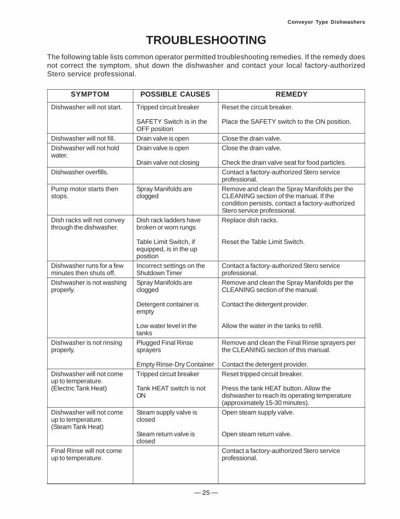
SYMPTOM
Dishwasher will not start.
Dishwasher will not fill.Dishwasher will not holdwater.
Dishwasher overfills.
Pump motor starts thenstops.
Dish racks will not conveythrough the dishwasher.
Dishwasher runs for a fewminutes then shuts off.Dishwasher is not washingproperly.
Dishwasher is not rinsingproperly.
Dishwasher will not comeup to temperature.(Electric Tank Heat)
Dishwasher will not comeup to temperature.(Steam Tank Heat)
Final Rinse will not comeup to temperature.
POSSIBLE CAUSES
Tripped circuit breaker
SAFETY Switch is in theOFF positionDrain valve is openDrain valve is open
Drain valve not closing
Spray Manifolds areclogged
Dish rack ladders havebroken or worn rungs
Table Limit Switch, ifequipped, is in the uppositionIncorrect settings on theShutdown TimerSpray Manifolds areclogged
Detergent container isempty
Low water level in thetanksPlugged Final Rinsesprayers
Empty Rinse-Dry ContainerTripped circuit breaker
Tank HEAT switch is notON
Steam supply valve isclosed
Steam return valve isclosed
REMEDY
Reset the circuit breaker.
Place the SAFETY switch to the ON position.
Close the drain valve.Close the drain valve.
Check the drain valve seat for food particles.Contact a factory-authorized Stero serviceprofessional.Remove and clean the Spray Manifolds per theCLEANING section of the manual. If thecondition persists, contact a factory-authorizedStero service professional.Replace dish racks.
Reset the Table Limit Switch.
Contact a factory-authorized Stero serviceprofessional.Remove and clean the Spray Manifolds per theCLEANING section of the manual.
Contact the detergent provider.
Allow the water in the tanks to refill.
Remove and clean the Final Rinse sprayers perthe CLEANING section of this manual.
Contact the detergent provider.Reset tripped circuit breaker.
Press the tank HEAT button. Allow thedishwasher to reach its operating temperature(approximately 15-30 minutes).Open steam supply valve.
Open steam return valve.
Contact a factory-authorized Stero serviceprofessional.
TROUBLESHOOTINGThe following table lists common operator permitted troubleshooting remedies. If the remedy doesnot correct the symptom, shut down the dishwasher and contact your local factory-authorizedStero service professional.

— 26 —
Conveyor Type Dishwashers
PRODUCT SUPPORT AND SERVICETo obtain service and parts information concerning this model, contact the Stero authorizedservice provider in your area (refer to our website, www.stero.com, for a complete listingof authorized service and parts locations).
When calling for service, the following information must be available:
• Model Number: ___________________
• Serial Number: ____________________
• Voltage: __________________________

— 27 —
Conveyor Type Dishwashers
STERO WARRANTYThis warranty is in lieu of all other warranties,expressed or implied, including withoutl imitat ion any implied warranty ofmerchantability, fitness for a particular purposeor non–infringement, and of any otherobligation or liability on the part of Stero, whetherin contract, strict liability, tort or otherwise.
The Stero Company warrants this equipmentto be free from defects in material andworkmanship, under normal use and operation,for a period of one (1) year from the date ofinitial start up or eighteen (18) months fromthe date of shipment from the factory,whichever comes first. This warranty isconditioned upon the customer’s maintenanceand care as outlined in the service manualand upon return of the warranty registrationcard. Repairs will be performed during Stero’sauthorized service agency’s normal businesshours. If the customer requires after hoursservice, the customer will be responsible forthe overtime premium.
Machine is warranted only for the initial placeof instal lat ion. Removal of machineautomatically terminates the warranty. Steroshall have no liability under this warranty unlessthe customer promptly notifies Stero or itsfactory authorized service agent of any allegeddefects. All defective parts become theproperty of Stero and must be returned toStero, or its agent, at Stero’s expense, withinthirty (30) days from the date of the part’sreplacement. Parts replaced within thewarranty carry only the unexpired portion of
the machine’s warranty. Not covered by thiswarranty are changes (parts and/or labor)necessitated by or damage resulting from:water condit ions, accident, alteration,improper use, abuse, tampering, improperinstallation, or failure to follow operating andmaintenance procedures. Examples of theforegoing, but without limitations are: (1)Damage to the machine resulting fromexcessive concentrations of chlorine or de–liming acid solutions; (2) Use with utility serviceother than designated on the rating plates; (3)Improper connection to utility service; (4)Inadequate or excessive water and/or steampressure; (5) Leaks caused by faultyinstallation; (6) Component failures causedby water leaks due to faulty installation; (7)Failure to comply to local building codes; (8)Failures due to deposits resulting from wateror steam conditions, detergents, chemicals,or improper cleaning; (9) Resetting breakers,overloads, or safety thermostats; (10)Adjustments of thermostats after 90 days ofoperation; (11) Improper opening of utilitysupply valves; (12) Cleaning drain valves, linestrainers, rinse nozzles, etc.; (13) Improperinstallation or malfunction of chemicaldispensing equipment supplied by others; and(14) Failure to provide regular maintenanceand daily cleaning as outlined in the servicemanual. In no event will Stero be liable for lossor damage to or loss of use of facilities orother property, additional labor costs, loss ofrevenue, loss of anticipated profits, or otherdamages of any kind what–so–ever, whetherdirect, indirect, incidental or consequential.
— 28 —
Conveyor Type Dishwashers
The State of California enacted the CaliforniaSafe Drinking Water and Toxic EnforcementAct of 1986, (Prop. 65), which "prohibits anyperson in the course of doing business fromknowingly and intentionally exposing anyindividual to a chemical known to the State ofCalifornia to cause cancer or reproductivetoxicity without first giving clear and reasonablewarning to such individuals." The Governor’sScientific Advisory Panel added carbonmonoxide to the list of hazardous chemicalsknown to cause reproductive harm.
In order to establish full compliance withProposition 65, an orange warning label hasbeen attached to each gas-f ired unitmanufactured by Stero.
Carbon monoxide would not be present inconcentrations that would pose a "significantrisk" to the consumer when the equipment isinstalled, operated and maintained as follows:
1. Installed in accordance with all local codes,or in the absence of local codes, with thecurrent National Fuel Gas Code ANSIZ223.1 Latest Addenda.
2. Installed under a properly designed andoperating exhaust hood.
3. Connected to the type of gas for which theunit is equipped.
4. Proper appliance pressure regulatorinstalled on the gas supply line andadjusted for the manifold pressure markedon the rating plate.
5. Adequate air supply to the unit.
6. The equipment is operated in the mannerintended and using the proper utensil forthat type of appliance.
7. Keep the equipment clean and have itchecked periodically.
8. Burner air adjustments, mechanicalmaintenance and repairs must beperformed by qualified service personnel.
If the equipment is not installed, operated andmaintained in accordance with the aboverequirements, concentrations of carbonmonoxide in excess of the established limitscould be present in the kitchen environment.
If not installed, operated and maintained in accordance with themanufacturer’s instructions, this product could expose you to fuel or fuel combustionsubstances, which can cause death or serious illness and which are known to the State ofCalifornia to cause cancer, birth defects or other reproductive harm.
ALL PERSONNEL IN THE WORKPLACE WHO MAY BE SUBJECT TO ANYEXPOSURE OF CARBON MONOXIDE MUST BE WARNED OF SUCH POSSIBLEEXPOSURE. THIS WARNING SHOULD BE CONVEYED IN A MANNER SO THATIT IS CLEARLY UNDERSTOOD BY THE EMPLOYEE. THE EMPLOYEE MUSTBE ASKED IF IN FACT HE OR SHE UNDERSTANDS THE CORRECT METHODOF OPERATION OF THE EQUIPMENT AND THAT A RISK OF EXPOSUREEXISTS IF THE EQUIPMENT IS OPERATED IMPROPERLY.

— 29 —
Conveyor Type Dishwashers
NOTES

— 30 —
Conveyor Type Dishwashers
NOTES
STERO, A DIVISION OF ILLINOIS TOOL WORKS INC.WWW.STERO.COM
3200 LAKEVILLE HWY.PETALUMA, CA 94954
Telephone: 800-762-7600Fax: 707-762-5036

— 31 —
Conveyor Type Dishwashers
New Equipment Performance and Installation Inspection Report
Date:
Customer Information
Location Contact Name
Address City State
Phone Fax Zip
Service Agency Information
Company Technician Name
City State PhoneZip
Equipment Information
Model Serial Number
Date of Installation
All new Stero Dishwashing Machines are warranted against defects in workmanship and materials for a period of one year from date of start-up by the original owner. Warranty card MUST be filled out and RETURNED to the manufacturer within 10 days from the date of delivery to the original owner. Warranty does not apply to any dishwasher which has been subject to accident, alteration, misuse or damages resulting from incorrect installation on the part of the contractor.
Any repair work performed on the above dishmachine by persons other than Authorized Stero Service Agencies is the sole responsibility of the customer.
The above machine has been inspected and demonstrated in the presence of the customer by a representative authorized by Stero.
Stero Representative Signature Customer Signature
Installation Checklist
Machine leveledN/A OK
Voltage/Phase correct V Ph
Circuit breaker(s) sized correctly A
Water supply temperature meets min. requirements F
Water pressure meets min. requirements PSI
Plumbing checked for leaks
Fill/Drain lines plumbed correctly
Spray Manifolds in place and secure
Strainer Pans in place
Curtains in proper place
Wash Temperature F
RinseTemperature
Dampers adjusted/working properly
Demonstration Checklist (To be completed by Stero Representative)
OKN/ASoap dispenser installed
Motor rotation is correct
Water Temperatures
Scrapper Temperature
Auxiliary Rinse Temperature
Final Rinse Temperature
F
F
F
F
Booster Heater Information N/A
Manufacturer Model
Serial No.
PhV
Type of Heat
Customer Service Agent
Rinse Injector installed
OKN/ADemonstrated RUN cycle
Demonstrated Shutdown procedures
Warranty policy explained
Cleaning procedures explained
Parts manual included
Steam-Heated SWB Gas-Heated WC
PhV
Normal maintenance procedures demonstrated
N/A
Conveyor Belt Tension adjusted properly
Steam Condensate/Return line routed correctly
Cut
Her
e

— 32 —
Conveyor Type Dishwashers