08394053 monitor installation, operation, & maintenance ... · 08394053 monitor installation,...
TRANSCRIPT
1
08394053 Monitor Installation, Operation, & Maintenance Instructions
2
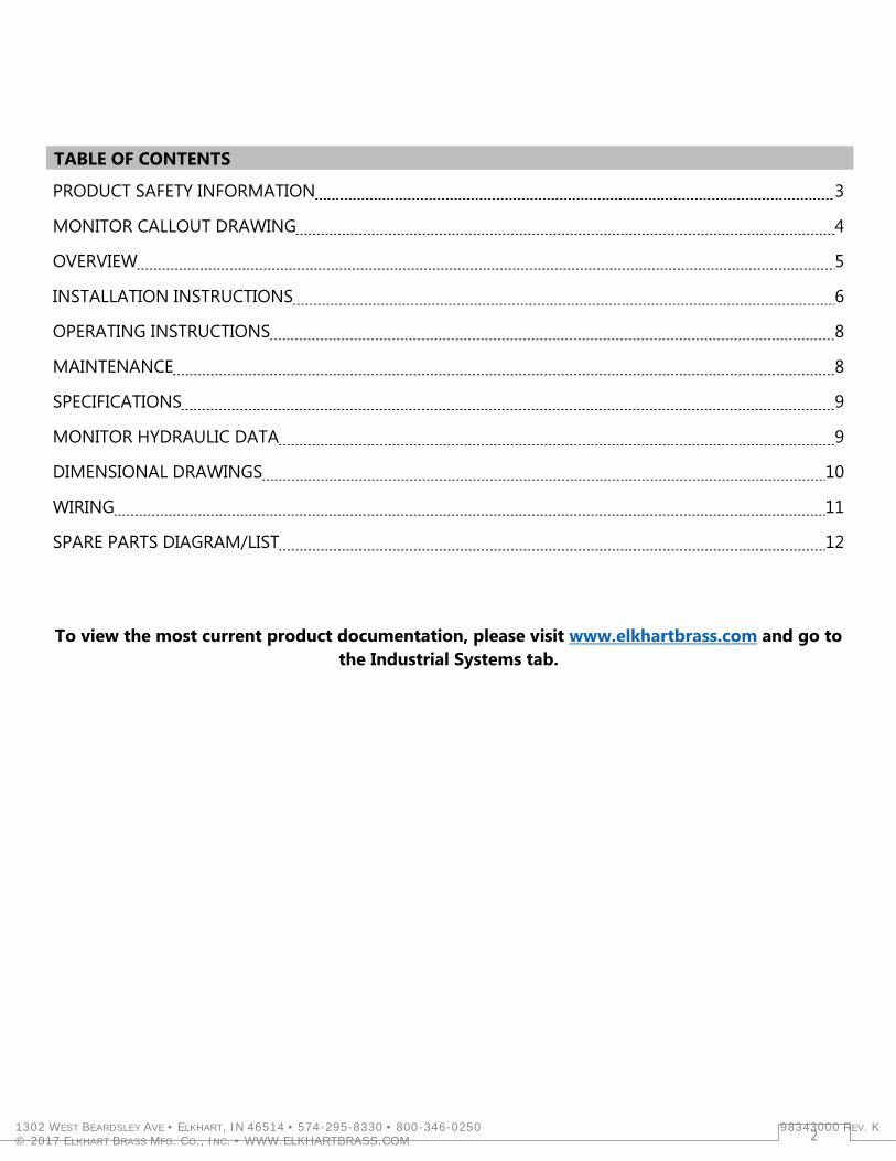
TABLE OF CONTENTS
PRODUCT SAFETY INFORMATION 3
MONITOR CALLOUT DRAWING 4
OVERVIEW 5
INSTALLATION INSTRUCTIONS 6
OPERATING INSTRUCTIONS 8
MAINTENANCE 8
SPECIFICATIONS 9
MONITOR HYDRAULIC DATA 9
DIMENSIONAL DRAWINGS 10
WIRING 11
SPARE PARTS DIAGRAM/LIST 12
To view the most current product documentation, please visit www.elkhartbrass.com and go to
the Industrial Systems tab.
1302 WEST BEARDSLEY AVE • ELKHART, IN 46514 • 574-295-8330 • 800-346-0250 98343000 REV. K © 2017 ELKHART BRASS MFG. CO., INC. • WWW.ELKHARTBRASS.COM
3
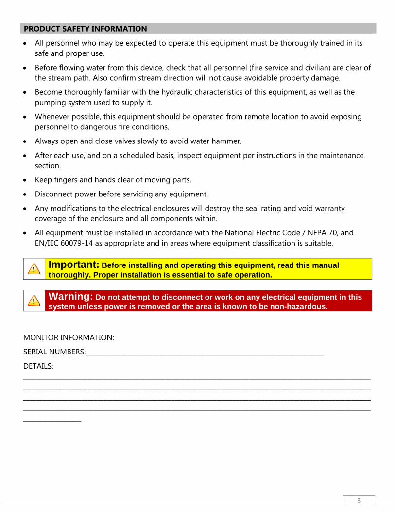
PRODUCT SAFETY INFORMATION
• All personnel who may be expected to operate this equipment must be thoroughly trained in its safe and proper use.
• Before flowing water from this device, check that all personnel (fire service and civilian) are clear of the stream path. Also confirm stream direction will not cause avoidable property damage.
• Become thoroughly familiar with the hydraulic characteristics of this equipment, as well as the pumping system used to supply it.
• Whenever possible, this equipment should be operated from remote location to avoid exposing personnel to dangerous fire conditions.
• Always open and close valves slowly to avoid water hammer.
• After each use, and on a scheduled basis, inspect equipment per instructions in the maintenance section.
• Keep fingers and hands clear of moving parts.
• Disconnect power before servicing any equipment.
• Any modifications to the electrical enclosures will destroy the seal rating and void warranty coverage of the enclosure and all components within.
• All equipment must be installed in accordance with the National Electric Code / NFPA 70, and EN/IEC 60079-14 as appropriate and in areas where equipment classification is suitable.
Important: Before installing and operating this equipment, read this manual thoroughly. Proper installation is essential to safe operation.
Warning: Do not attempt to disconnect or work on any electrical equipment in this system unless power is removed or the area is known to be non-hazardous.
MONITOR INFORMATION:
SERIAL NUMBERS:__________________________________________________________________________
DETAILS: __________________________________________________________________________________________________________________________________________________________________________________________________________________________________________________________________________________________________________________________________________________________________________________________________________________________________________________________________
4
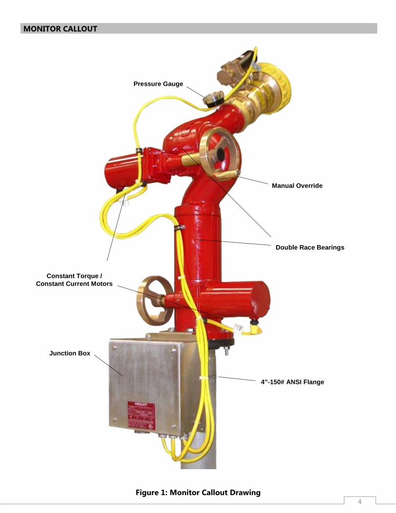
MONITOR CALLOUT
Figure 1: Monitor Callout Drawing
Pressure Gauge
Constant Torque / Constant Current Motors
Manual Override
Double Race Bearings
Junction Box
4”-150# ANSI Flange
5
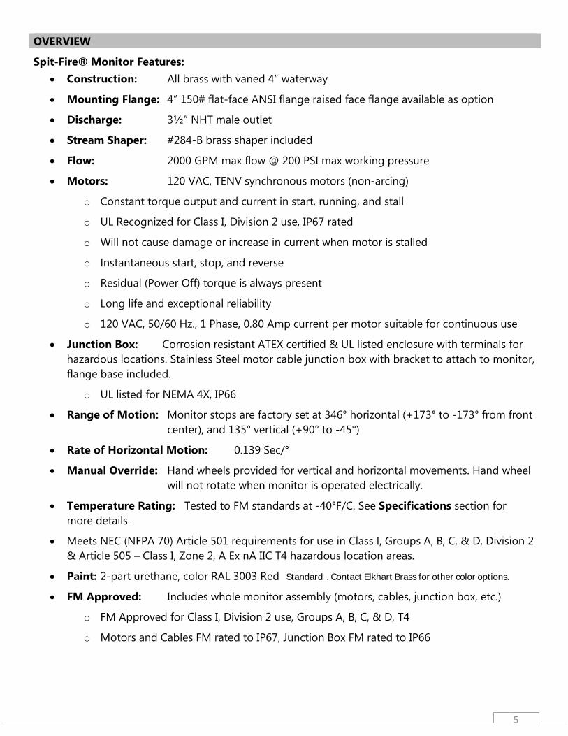
OVERVIEW
Spit-Fire® Monitor Features: • Construction: All brass with vaned 4” waterway
• Mounting Flange: 4” 150# flat-face ANSI flange raised face flange available as option
• Discharge: 3½” NHT male outlet
• Stream Shaper: #284-B brass shaper included
• Flow: 2000 GPM max flow @ 200 PSI max working pressure
• Motors: 120 VAC, TENV synchronous motors (non-arcing)
o Constant torque output and current in start, running, and stall
o UL Recognized for Class I, Division 2 use, IP67 rated
o Will not cause damage or increase in current when motor is stalled
o Instantaneous start, stop, and reverse
o Residual (Power Off) torque is always present
o Long life and exceptional reliability
o 120 VAC, 50/60 Hz., 1 Phase, 0.80 Amp current per motor suitable for continuous use
• Junction Box: Corrosion resistant ATEX certified & UL listed enclosure with terminals for hazardous locations. Stainless Steel motor cable junction box with bracket to attach to monitor, flange base included.
o UL listed for NEMA 4X, IP66
• Range of Motion: Monitor stops are factory set at 346° horizontal (+173° to -173° from front center), and 135° vertical (+90° to -45°)
• Rate of Horizontal Motion: 0.139 Sec/°
• Manual Override: Hand wheels provided for vertical and horizontal movements. Hand wheel will not rotate when monitor is operated electrically.
• Temperature Rating: Tested to FM standards at -40°F/C. See Specifications section for more details.
• Meets NEC (NFPA 70) Article 501 requirements for use in Class I, Groups A, B, C, & D, Division 2 & Article 505 – Class I, Zone 2, A Ex nA IIC T4 hazardous location areas.
• Paint: 2-part urethane, color RAL 3003 Red (Standard). Contact Elkhart Brass for other color options.
• FM Approved: Includes whole monitor assembly (motors, cables, junction box, etc.)
o FM Approved for Class I, Division 2 use, Groups A, B, C, & D, T4
o Motors and Cables FM rated to IP67, Junction Box FM rated to IP66
6
Warning: DO NOT TAKE COVER OFF OR DISASSEMBLE MONITOR MOTORS. If cover is/has been removed, the warranty is void and the service life of the motor is significantly reduced.
INSTALLATION INSTRUCTIONS
Intended Installation: This monitor is intended to be installed and used in a variety of industrial application environments consistent with the specifications listed herein that typically represent areas where fire hazard exists. To provide continued readiness for operation in any environment regular maintenance and inspection is required. Monitor Installation
1. Attach companion flange to water supply pipe so that the bolt pattern will allow the monitor to be installed with the “straight ahead/neutral” position (see Dimensional Drawing section) properly aligned. Alignment is correct when the “straight ahead/neutral” direction is centered between adjacent flange bolt holes.
2. Install the monitor assembly on the water supply flange so that it matches up to a 4”-150# flat faced ANSI flange on the inlet of the monitor, with a flange gasket between the flanges. Install motor cable junction box by aligning the two-holed bracket with the flange mounting holes on the rear of the monitor. Secure the inlet flange with eight (8) 5/8”-11 UNC Grade 5 hex head bolts. Torque bolts to 60-70 ft.-lbs. Tighten junction box cover screws (4) to 60 in-lbs.
3. Standpipe must be structurally strong enough to withstand reaction forces of the nozzle when discharging a straight stream at 90° of the standpipe tower. The formula for calculating nozzle reaction is: [REACTION FORCE = 0.0505 x GPM x √ PSI]
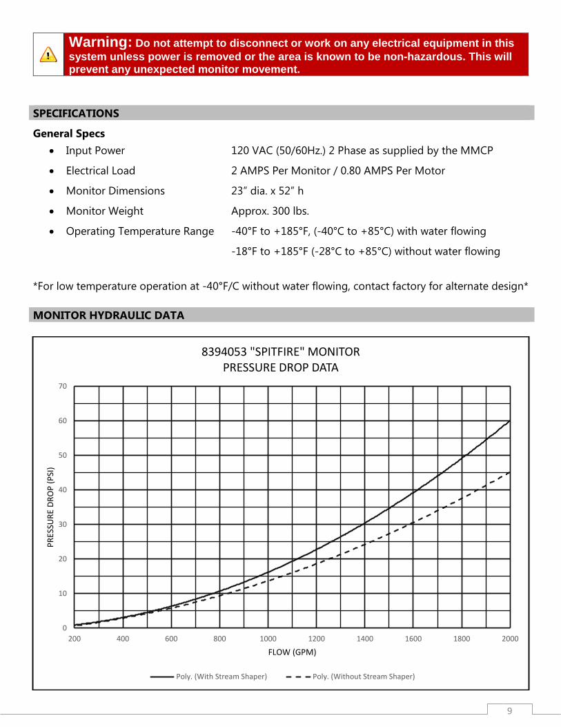
4. The inlet pressure at the base of the monitor must be high enough to allow for pressure loss through the monitor. To accomplish this, use the pressure loss for GPM flowing and add to nozzle pressure. See Monitor Hydraulic Data section for pressure loss chart.
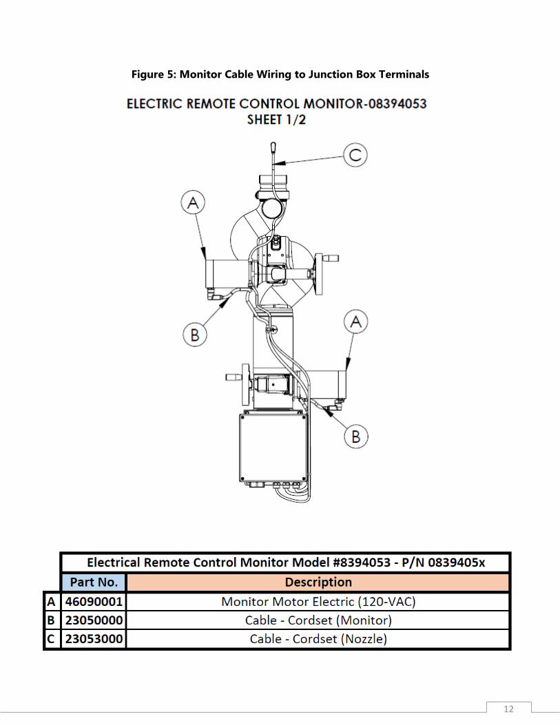
5. Install conduit between MMCP and the Junction Box located at the flanged base of monitor. Junction boxes are provided with 1 ½” NPT conduit hubs. Refer to figure 5 below and refer to MMCP manual for wiring information.
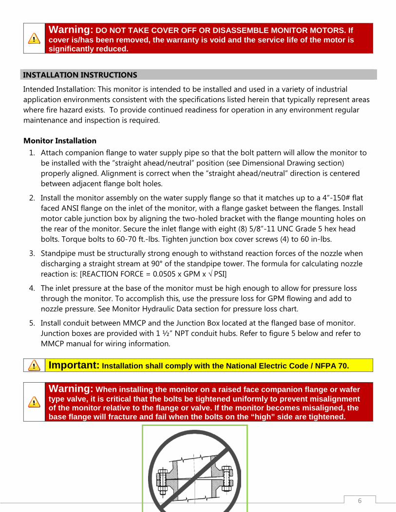
Important: Installation shall comply with the National Electric Code / NFPA 70.
Warning: When installing the monitor on a raised face companion flange or wafer type valve, it is critical that the bolts be tightened uniformly to prevent misalignment of the monitor relative to the flange or valve. If the monitor becomes misaligned, the base flange will fracture and fail when the bolts on the “high” side are tightened.

7
Monitor Cable Routing
1. Route cables as shown in Figure 2 below, so they will follow the vertical and horizontal movement of the monitor. Make sure that the wire loops for horizontal and vertical movement is great enough to eliminate any stretching of cables throughout the full movement of the monitor.
2. Wire tie cables together as shown in Figure 2 below. This will eliminate the cables from tangling.
3. Wire tie the nozzle cable to pressure gauge, allowing a long enough loop so vertical movement of monitor will go to the full down position without stretching the cable.
4. Alternate cable routings are acceptable, but the monitor must be able to move freely through full range of motion without stretching, tangling, or destroying any cables.
8
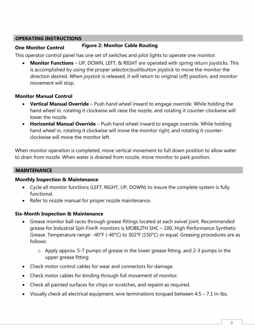
OPERATING INSTRUCTIONS
One Monitor Control This operator control panel has one set of switches and pilot lights to operate one monitor.
• Monitor Functions – UP, DOWN, LEFT, & RIGHT are operated with spring return joysticks. This is accomplished by using the proper selector/pushbutton joystick to move the monitor the direction desired. When joystick is released, it will return to original (off) position, and monitor movement will stop.
Monitor Manual Control
• Vertical Manual Override – Push hand wheel inward to engage override. While holding the hand wheel in, rotating it clockwise will raise the nozzle, and rotating it counter-clockwise will lower the nozzle.
• Horizontal Manual Override – Push hand wheel inward to engage override. While holding hand wheel in, rotating it clockwise will move the monitor right, and rotating it counter-clockwise will move the monitor left.
When monitor operation is completed, move vertical movement to full down position to allow water to drain from nozzle. When water is drained from nozzle, move monitor to park position. MAINTENANCE
Monthly Inspection & Maintenance • Cycle all monitor functions (LEFT, RIGHT, UP, DOWN) to insure the complete system is fully
functional. • Refer to nozzle manual for proper nozzle maintenance.
Six-Month Inspection & Maintenance
• Grease monitor ball races through grease fittings located at each swivel joint. Recommended grease for Industrial Spit-Fire® monitors is MOBILITH SHC – 100, High Performance Synthetic Grease. Temperature range: -40°F (-40°C) to 302°F (150°C) or equal. Greasing procedures are as follows:
o Apply approx. 5-7 pumps of grease in the lower grease fitting, and 2-3 pumps in the upper grease fitting
• Check motor control cables for wear and connectors for damage.
• Check motor cables for binding through full movement of monitor.
• Check all painted surfaces for chips or scratches, and repaint as required.
• Visually check all electrical equipment, wire terminations torqued between 4.5 – 7.1 in-lbs.
Figure 2: Monitor Cable Routing
9
Warning: Do not attempt to disconnect or work on any electrical equipment in this system unless power is removed or the area is known to be non-hazardous. This will prevent any unexpected monitor movement.
SPECIFICATIONS
General Specs • Input Power 120 VAC (50/60Hz.) 2 Phase as supplied by the MMCP
• Electrical Load 2 AMPS Per Monitor / 0.80 AMPS Per Motor
• Monitor Dimensions 23” dia. x 52” h
• Monitor Weight Approx. 300 lbs.
• Operating Temperature Range -40°F to +185°F, (-40°C to +85°C) with water flowing
-18°F to +185°F (-28°C to +85°C) without water flowing
*For low temperature operation at -40°F/C without water flowing, contact factory for alternate design* MONITOR HYDRAULIC DATA
0
10
20
30
40
50
60
70
200 400 600 800 1000 1200 1400 1600 1800 2000
PRES
SURE
DRO
P (P
SI)
FLOW (GPM)
8394053 "SPITFIRE" MONITORPRESSURE DROP DATA
Poly. (With Stream Shaper) Poly. (Without Stream Shaper)
10
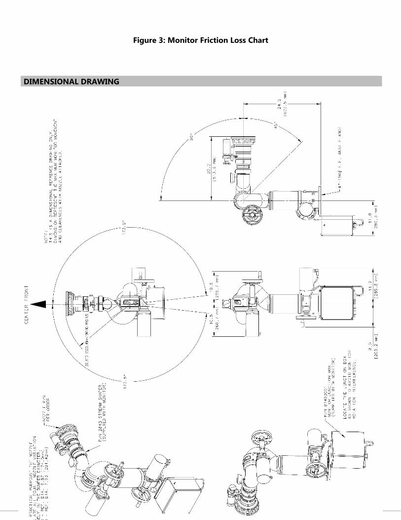
DIMENSIONAL DRAWING
Figure 3: Monitor Friction Loss Chart
11
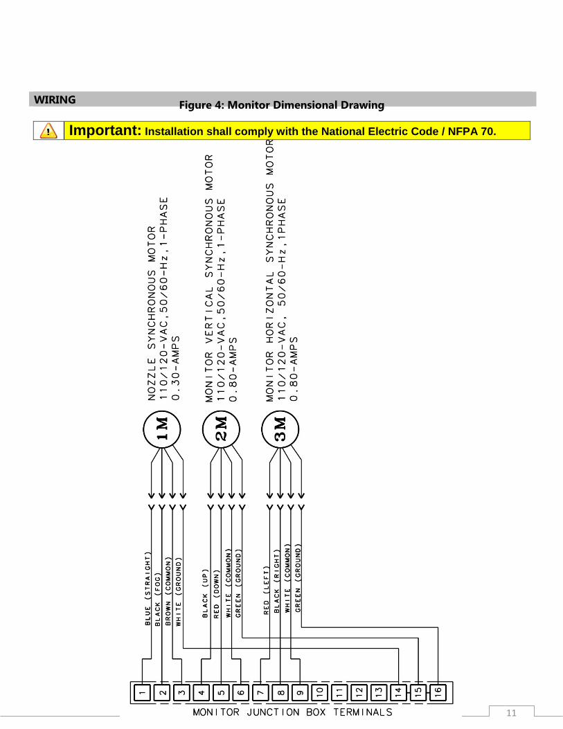
WIRING
Important: Installation shall comply with the National Electric Code / NFPA 70.
Figure 4: Monitor Dimensional Drawing
12
Figure 5: Monitor Cable Wiring to Junction Box Terminals
Revision J – ECN 160806
08/22/2016 • Page 12 o Added Spare Parts Diagram/List
Revision K – ECN 170516 05/24/2017
• Page 5,9 o Clarified note on monitor operation temperatures.
ELKHART BRASS 1302 WEST BEARDSLEY AVE P.O. BOX 1127 ELKHART, IN 46514 PHONE: 574-295-8330 • 800-346-0250 FAX: 574-293-9914 WWW.ELKHARTBRASS.COM © ELKHART BRASS MFG. CO., INC. 2017 SPIT-FIRE® 08394053 MONITOR INSTALLATION, OPERATION, & MAINTENANCE INSTRUCTIONS 98343000 REV. K