089 ' # '6& *#0 & 7cdn.intechopen.com/pdfs-wm/28863.pdf · daniela craciun 1,2,...
TRANSCRIPT

3,350+OPEN ACCESS BOOKS
108,000+INTERNATIONAL
AUTHORS AND EDITORS115+ MILLION
DOWNLOADS
BOOKSDELIVERED TO
151 COUNTRIES
AUTHORS AMONG
TOP 1%MOST CITED SCIENTIST
12.2%AUTHORS AND EDITORS
FROM TOP 500 UNIVERSITIES
Selection of our books indexed in theBook Citation Index in Web of Science™
Core Collection (BKCI)
Chapter from the book Modeling and Simulation in EngineeringDownloaded from: http://www.intechopen.com/books/modeling-and-s imulation-in-engineering
PUBLISHED BY
World's largest Science,Technology & Medicine
Open Access book publisher
Interested in publishing with IntechOpen?Contact us at [email protected]

Daniela Craciun1,2, Nicolas Paparoditis2 and Francis Schmitt1
1Telecom ParisTech CNRS URA 820 - TSI Dept.2Institut Geographique National - Laboratoire MATIS
France
1. Introduction
One might wonder what can be gained from the image-laser fusion and in which measuresuch a hybrid system can generate automatically complete and photorealist 3D models ofdifficult to access and unstructured underground environments.Our research work is focused on developing a vision-based system aimed at automaticallygenerating in-situ photorealist 3D models in previously unknown and unstructuredunderground environments from image and laser data. In particular we are interested inmodeling underground prehistoric caves. In such environments, special attention must begiven to the main issue standing behind the automation of the 3D modeling pipeline whichis represented by the capacity to match reliably image and laser data in GPS-denied andfeature-less areas. In addition, time and in-situ access constraints require fast and automaticprocedures for in-situ data acquisition, processing and interpretation in order to allow forin-situ verification of the 3D scene model completeness. Finally, the currently generated 3Dmodel represents the only available information providing situational awareness based onwhich autonomous behavior must be built in order to enable the system to act intelligentlyon-the-fly and explore the environment to ensure the 3D scene model completeness.This chapter evaluates the potential of a hybrid image-laser system for generating in-situcomplete and photorealist 3D models of challenging environments, while minimizing humanoperator intervention. The presented research focuses on two main aspects: (i) the automationof the 3D modeling pipeline, targeting the automatic data matching in feature-less andGPS-denied areas for in-situ world modeling and (ii) the exploitation of the generated 3Dmodels along with visual servoing procedures to ensure automatically the 3D scene modelcompleteness.We start this chapter by motivating the jointly use of laser and image data and by listing themain key issues which need to be addressed when aiming to supply automatic photorealist3D modeling tasks while coping with time and in-situ access constraints. The next foursections are dedicated to a gradual description of the 3D modeling system in which we projectthe proposed image-laser solutions designed to be embedded onboard mobile plateforms,providing them with world modeling capabilities and thus visual perception. This is an
Image-Laser Fusion for In Situ 3D Modeling of Complex Environments:
A 4D Panoramic-Driven Approach
1
www.intechopen.com

2 Will-be-set-by-IN-TECH
important aspect for the in-situ modeling process, allowing the system to be aware and toact intelligently on-the-fly in order to explore and digitize the entire site. For this reason, weintroduce it as ARTVISYS, the acronym for ARTificial VIsion-based SYStem.
2. The in-situ 3D modeling problem
The in-situ 3D modeling problem is concerned with the automatic environment sensingthrough the use of active (laser) and/or passive (cameras) 3D vision and aims at generatingin-situ the complete 3D scene model in a step by step fashion. At each step, the currentlygenerated 3D scene model must be exploited along with visual servoing procedures in orderto guide the system to act intelligently on-the-fly to ensure in-situ the 3D scene modelcompleteness.Systems embedding active 3D vision are suitable for generating in-situ complete 3D modelsof previously unknown and high-risk environments. Such systems rely on visual-basedenvironment perception provided by a sequentially generated 3D scene representation.Onboard 3D scene representation for navigation purposes was pioneered by Moravec’sback in the 1980s (Moravec, 1980). Since then, Computer Vision and Robotics researchcommunities have intensively focused their efforts to provide vision-based autonomousbehavior to unmanned systems, special attention being given to the vision-based autonomousnavigation problem. In (Nister et al., 2004), Nister demonstrated the feasibility of a purelyvision-based odometry system, showing that an alternative for localization in GPS-deniedareas can rely on artificial vision basis. Several research works introduced either 2D and 3DSimultaneous Localization and Mapping (SLAM) algorithms using single-camera or stereovision frameworks (Durrant-White & Bailey, 2006), (Bailey & Durrant-White, 2006). Whilegaining in maturity, these techniques rely on radiometric and geometric features’ existenceor exploit initial guess provided by navigation sensors (GPS, IMUs, magnetic compasses)employed along with dead-reckoning procedures.Scientists from Robotics, Computer Vision and Graphics research communities wereintroducing the 3D modeling pipeline (Beraldin & Cournoyer, 1997) aiming to obtainphotorealist digital 3D models through the use of 3D laser scanners and/or cameras. Various3D modeling systems have been developed promoting a wide range of applications: culturalheritage (Levoy et al., 2000), (Ikeuchi et al., 2007),(Banno et al., 2008), 3D modeling of urbanscenes (Stamos et al., 2008), modeling from real world scenes (Huber, 2002), natural terrainmapping and underground mine mapping (Huber & Vandapel, 2003), (Nuchter et al., 2004),(Thrun et al., 2006).Without loss of generality, the 3D modeling pipeline requires automatic procedures for dataacquisition, processing and 3D scene model rendering. Due to the sensors’ limited field ofview and occlusions, multiple data from various viewpoints need to be acquired, alignedand merged in a global coordinate system in order to provide a complete and photorealist3D scene model rendering. As for SLAM techniques, the main drawback standing behindthe automation of the entire 3D modeling process is the data alignment step for which severalmethods have been introduced.For systems focusing on 3D modeling of large-scale objects or monuments (Levoy et al.,2000), (Ikeuchi et al., 2007),(Banno et al., 2008) a crude alignment is performed by an operatoroff-line. Then the coarse alignment is refined via iterative techniques (Besl & McKay, 1992).However, during the post-processing step it is often observed that the 3D scene model is
4 Modeling and Simulation in Engineering
www.intechopen.com

Image-Laser Fusion for In-Situ 3D Modeling of Complex Environments: a 4D Panoramic-Driven Approach 3
incomplete. Although data alignment using artificial markers produces accurate results,it cannot be applied to high-risk environments due to time and in-situ access constraints.In addition, for cultural heritage applications, placing artificial landmarks within the scenecauses damages to the heritage hosted by the site. The critical need for an in-situ 3D modelingprocedure is emphasized by the operator’s difficulty to access too small and too dangerousareas for placing artificial landmarks and by the need to validate in-situ the 3D scene modelcompleteness in order to avoid to return on site to complete data collection.Existing automatic data alignment methods perform coarse alignment by exploiting priorknowledge over the scene’s content (Stamos et al., 2008) (i.e. radiometric or geometricfeatures’ existence, regular terrain to navigate with minimal perception) or the possibility torely on navigation sensors (GPS, INS, odometry, etc.). In a second step, a fine alignment isperformed via iterative methods.Since in our research work the environment is previously unknown, features’ existence cannotbe guaranteed. In addition, in underground environments and uneven terrain navigationsensors are not reliable and dead-reckoning techniques lead to unbounded error growth forlarge-scale sceneries. A notable approach reported by Johnson (Johnson, 1997) and improvedby Huber (Huber, 2002) overcomes the need of odometry using shape descriptors for 3Dpoint matching. However, shape descriptors’ computation requires dense 3D scans, leading totime consuming acquisition and processing, which does not cope with time and in-situ accessconstraints.A main part of this chapter focuses on providing image-laser solutions for addressing theautomation of the 3D modeling pipeline by solving the data alignment problem in feature-lessand GPS-denied areas. In a second phase, we propose to exploit the world modelingcapability along with visual servoing procedures in order to ensure in-situ the 3D scene modelcompleteness.
3. Proposed solution: Automatic 3D modeling through 4D mosaic views
This section resumes how we solve for the automation of the 3D modeling pipeline throughthe use of 4D mosaics. We start by introducing the hardware design and by summarizing the4D-mosaicing process. In order to ensure in-situ the 3D scene model completeness, Section3.3 proposes a 4D-mosaic driven acquisition scenario having as main scope the automaticdigitization and exploration of the site.
3.1 Testbed. Hard- and soft-ware architecture
We designed a dual system for performing in-situ 3D modeling tasks in large-scale, complexand difficult to access underground environments. Since in such environments navigationsensors are not reliable, the proposed system embeds only 2D and 3D vision sensors, unifyingphotorealism and high resolution geometry into 4D mosaic views. Figure 1 illustrates theARTVISYS’s hardware along with the proposed 4D-mosaicing process. We describe hereafterseveral ARTVISYS’s features and justify the proposed design.RACL1 dual-system (Craciun, 2010). The proposed hardware architecture falls in thecategory of the RACL dual sensing devices, embedding a high-resolution color cameramounted on a motorized pan-tilt unit and a 3D laser-range-finder, which are depicted inFigures 1 a) and b), respectively. There are several reasons for choosing a RACL design:
1 RACL system: Rigidly Attached Camera Laser system
5Image-Laser Fusion for In Situ 3D Modeling of Complex Environments: A 4D Panoramic-Driven Approach
www.intechopen.com

4 Will-be-set-by-IN-TECH
Fig. 1. The 4D-mosaicing process proposed for integration onboard ARTVISYS. a) NIKOND70 � digital camera mounted on Rodeon � motorized pan-tilt unit, b) Trimble � 3Dlaser-range-finder during a data acquisition campaign undertaken in the Tautavel prehistoriccave (France) by the French Mapping Agency in October 2007, c) a Gigapixel color mosaicresulted from an image sequence acquired in the Tautavel prehistoric cave using anautomatic image stitching algorithm which we introduce in Section 5 of this chapter, d) a 3Dmosaic resulted from several overlapped scans acquired in the Tautavel prehistoric cave,matched by an automatic multi-view scan-matcher proposed in Section 4, e) alignment the3D mosaic onto the Gigapixel one to produce the 4D mosaic, process described in Section 6 ofthis chapter.
• image-laser complementarity has been widely emphasized and investigated by severalresearch works (Dias et al., 2003), (Stamos et al., 2008), (Zhao et al., 2005), (Cole &Newman, 2006), (Newman et al., 2006). There is no doubt that employing the two sensorsseparately, none can solve for the 3D modeling problem reliably.
• RACL systems overcomes several shortcomings raised by FMCL2 ones. In particular,image-laser alignment and texture mapping procedures are difficult due to occluded areasin either image or laser data.
Addressing time and in-situ access constraints. An in-situ 3D modeling system must beable to supply fast data acquisition and processing while assuring the 3D scene modelcompleteness in order to avoid to return on site to collect new data.To this end, we design a complementary and cooperative image-laser fusion which lead to a 4Dmosaicing sensor prototype. The complementary aspect is related to the data acquisition process:in order to deal with time and in-situ access constraints, the proposed acquisition protocolconsists in acquiring low-resolution 3D point clouds and high-resolution color images togenerate in-situ photorealist 3D models. The use of both sensors rigidly attached leads to acooperative fusion, producing a dual sensing device capable to generate in-situ omnidirectionaland photorealist 3D models encoded as 4D mosaic views, which to our knowledge are noachievable using each sensor separately.
2 Freely Moving Camera Laser system
6 Modeling and Simulation in Engineering
www.intechopen.com

Image-Laser Fusion for In-Situ 3D Modeling of Complex Environments: a 4D Panoramic-Driven Approach 5
Fig. 2. a) Trimble � laser range finder delivering 5000 points per second with an accuracy of3mm at 100m. The dimensions of the laser range finders are: 340mm diameter, 270mm widthand 420mm height. The weight of the capturing device is 13.6kg. b) the field of view coveredby the sensor.
3.2 Introducing 4D mosaic views: omnidirectional photorealist 3D models
In this chapter we solve for the automation of the 3D modeling pipeline by introducing the4D mosaic views as fully spherical panoramic data structure encoding surface geometry (depth)and 3-channel color information (red, green and blue). A 4D mosaic is generated within threesteps (process illustrated in Figure 1), each of which being described in Sections 4, 5 and 6 ofthis chapter and for which we provide a brief description hereafter.3D Mosaics from laser-range-finders (LRFs). First, a 3D laser scanner acquires severalpartially overlapped scans which are aligned and merged into a fully 3D spherical mosaicview via a multi-view scan matching algorithm for which a detailed description is providedin Section 4. Figure 1 d) illustrates an example of a 3D mosaic obtained from real dataacquired in the Tautavel prehistoric cave. Since our work is concerned with the 3D modelingin unstructured and underground environments, we introduce an automatic scan matcherwhich replaces the two-post processing steps usually performed by the currently existingscans alignment techniques (coarse alignment via manual or GPS pose and ICP-like methodsfor fine registration). The proposed method does not rely on feature extraction and matching,providing thus an environment-independent method.Gigapixel panoramic head. Second, the motorized panoramic head illustrated in Figure 1a)acquires a sequence of high-resolution images which are further automatically stitched intoa Gigapixel color mosaic via a multi-view image matching algorithm for which a descriptionis given in Section 5. Figure 1 c) depicts an example of the obtained optical mosaic. Sincethe nowadays image stitching algorithms present several limitations when dealing withunstructured environments, one of our main concern in this chapter is the ability to matchimages in feature-less areas.4D-Mosaicing. Third, the 3D mosaic and the 2D optical Gigapixel one are aligned andfused into a photorealist and geometrically accurate 4D mosaic. This is the last step of the4D-mosaicing process corresponding to Figure 1 e) and for which a mosaic-based approachfor image-laser data alignment is proposed in Section 6. The estimated pose is exploited togenerate in-situ a 4D mosaic (4-channel: red, green, blue and depth) which to our knowledgehas not been reported until now.The proposed 3D modeling pipeline leads to a vision-based system capable to generate in-situphotorealist and highly accurate 3D models encoded as 4D mosaics for each ARTVISYS’s
7Image-Laser Fusion for In Situ 3D Modeling of Complex Environments: A 4D Panoramic-Driven Approach
www.intechopen.com

6 Will-be-set-by-IN-TECH
spatial position, called station. The next section introduces the 4D-mosaic-driven in-situ 3Dmodeling process performed by ARTVISYS aiming to ensure in-situ the 3D scene modelcompleteness.
3.3 4D Mosaic-driven in situ 3D modeling
When dealing with the in-situ 3D modeling problem in large scale complex environments, onehas to generate dynamically 3D scene models and to deal with occluded areas on-the-fly, inorder to ensure automatically the 3D scene model completeness. This calls for an intelligent3D modeling system, which implies the computation of the Next Best View (NBV) position(Dias et al., 2002) from which the new 4D mosaic must be acquired in order to sense theoccluded areas. In addition, the system must be able to navigate from it’s current position tothe next best estimated 3D pose from which the next 4D mosaic must be acquired. This impliespath planning, autonomous navigation and fast decision making capabilities. A detaileddescription on this process can be found in (Craciun, 2010).4D-mosaic-driven acquisition scenario. Due to occlusions, several 4D mosaics must beautonomously acquired from different 3D spatial positions of the system in order to maximizethe visible volume, while minimizing data redundancy. To this end, the 4D mosaicingsensor prototype comes together with a a 4D-mosaic-driven acquisition scenario performed ina stop-and-go fashion, as illustrated in Figure 3.The acquisition scenario starts by acquiring a 4D-mosaic which is further exploited to detectthe occluded areas. In Figure 3, they corresponds to the blue segments representing depthdiscontinuities associated to each station. In a second step, the system must estimate the3D pose from which the next 4D-mosaic must be acquired in order to maximize the visiblevolume. In a third step, the 4D mosaics are matched and integrated within a global 3D scenemodel which is further exploited to iterate the two aforementioned steps until the 3D scenemodel completeness is achieved.Unambigous wide-baseline data alignment. The main advantage of 4D-mosaic views isrepresented by the fact that they encode explicit color information as 3-channel components(i.e. red, green and blue) and implicit shape description as depth for a fully spherical viewof the system’s surroundings. The four dimensional components are required in order toensure reliably further processing, such as unambiguous data matching under wide viewpointvariation.
4. Multi-view rigid scans alignment for in-situ 3D mosaicing
This section presents the first step of the 4D mosaicing process introduced in Figure1. Wedescribe a multi-view scans alignment technique for generating in-situ 3D mosaics fromseveral partially overlapped scans acquired from the same 3D pose of the system. We firstdescribe the data acquisition scenario, followed by the global approach and an overview ofexperimental results obtained on real data gathered in two prehistoric caves are presented.
4.1 3D mosaicing acquisition scenario
In Section 3 we presented the hardware design of the proposed system which includes aTrimble� scanning device illustrated in Figure 2 a) providing a cloud of 3D points and theirassociated light intensity backscattering, within a field of view of 360◦ horizontally x 60◦
vertically, as shown in Figure 2 b). When mounted on a tripod, due to the vertical narrow
8 Modeling and Simulation in Engineering
www.intechopen.com

Image-Laser Fusion for In-Situ 3D Modeling of Complex Environments: a 4D Panoramic-Driven Approach 7
Fig. 3. The 4D-mosaic-driven acquisition scenario performed by ARTVISYS.
field of view, the scanning device is not suitable for the acquisition coverage of ceiling andground. Therefore, we manufactured in our laboratory a L-form angle-iron shown in Figure4 a).
Fig. 4. The 3D mosaicing acquisition geometry.
The L-mount-laser prototype illustrated in Figure 4 b) captures all the area around its opticalcenter within 360◦ vertically and 60◦ horizontally as shown in Figure 4 c), which we call avertical panoramic band (VPB). Given a spatial position of the tripod, which we call a station, the
9Image-Laser Fusion for In Situ 3D Modeling of Complex Environments: A 4D Panoramic-Driven Approach
www.intechopen.com
8 Will-be-set-by-IN-TECH
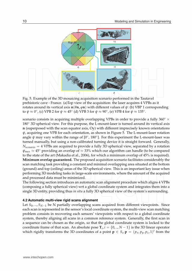
Fig. 5. Example of the 3D mosaicing acquisition scenario performed in the Tautavelprehistoric cave - France. (a)Top view of the acquisition: the laser acquires 4 VPBs as itrotates around its vertical axis n(θn, ϕn) with different values of ψ: (b) VBP 1 correspondingto ψ ≈ 0◦, (c) VPB 2 for ψ ≈ 45◦ (d) VPB 3 for ψ ≈ 90◦, (e) VPB 4 for ψ ≈ 135◦.
scenario consists in acquiring multiple overlapping VPBs in order to provide a fully 360◦ ×180◦ 3D spherical view. For this purpose, the L-mount-laser is turned around its vertical axisn (superposed with the scan equator axis, Oy) with different imprecisely known orientationsψ, acquiring one VPB for each orientation, as shown in Figure 5. The L-mount-laser rotationangle ψ may vary within the range of [0◦, 180◦]. For this experiment the L-mount-laser wasturned manually, but using a non-calibrated turning device it is straight forward. Generally,Nscenario = 4 VPBs are acquired to provide a fully 3D spherical view, separated by a rotationψmax ≃ 45◦ providing an overlap of ≃ 33% which our algorithm can handle (to be comparedto the state of the art (Makadia et al., 2006), for which a minimum overlap of 45% is required).Minimum overlap guaranteed. The proposed acquisition scenario facilitates considerably thescan matching task providing a constant and minimal overlapping area situated at the bottom(ground) and top (ceiling) areas of the 3D spherical view. This is an important key issue whenperforming 3D modeling tasks in large-scale environments, where the amount of the acquiredand processed data must be minimized.The following section introduces an automatic scan alignment procedure which aligns 4 VPBs(composing a fully spherical view) wrt a global coordinate system and integrates them into asingle 3D entity, providing thus in situ a fully 3D spherical view of the system’s surrounding.
4.2 Automatic multi-view rigid scans alignment
Let S0, ..., SN−1 be N partially overlapping scans acquired from different viewpoints. Sinceeach scan is represented in the sensor’s local coordinate system, the multi-view scan matchingproblem consists in recovering each sensors’ viewpoints with respect to a global coordinatesystem, thereby aligning all scans in a common reference system. Generally, the first scan ina sequence can be chosen as the origin, so that the global coordinate system is locked to thecoordinate frame of that scan. An absolute pose Ti, i = {0, .., N − 1} is the 3D linear operatorwhich rigidly transforms the 3D coordinates of a point p ∈ Si, p = (px, py, pz, 1)t from the
10 Modeling and Simulation in Engineering
www.intechopen.com

Image-Laser Fusion for In-Situ 3D Modeling of Complex Environments: a 4D Panoramic-Driven Approach 9
local coordinate system of scan Si to the global (or world) coordinate system: pw = Tipi. Inorder to estimate the absolute poses Ti, it is necessary to compute the relative poses Tij, j ={0, .., N − 1} and the corresponding overlaps Oij for each pair of scans via a pair-wise scanmatching procedure. Due to the mutual dependency which lies between the overlaps Oij andthe relative poses Tij, the multi-view scan matching is a difficult task.Pair-wise rigid poses. We developed a pair-wise scan matcher algorithm by matching 2Dpanoramic views, solving simultaneously the above interrelated problems using a pyramidaldense correlation framework via quaternions. The pair-wise scan matching procedureexploits either intensity or depth 2D panoramic views, which encode spatial and appearanceconstraints increasing therefore the robustness of the pair-wise scan matching process. Wesolve for the pose estimation in two steps, within a hybrid framework: the rotation R isfirst computed by matching either intensity or depth data in the 2D panoramic image space,while the residual translation is computed a posteriori by projecting back in the 3D space therotationally aligned panoramic images.The proposed method employs an adaptable pyramidal framework which is the key issue formodeling in occluded environments, providing robustness to large-scale sparse data sets andcutting down the combinatory. In addition, the pyramidal structure emphasizes the tradeoffbetween the two key aspects of any scan matcher, the accuracy and the robustness. In thiswork, the accuracy is related to the subpixel precision attached to the dense correlation step,while the robustness component is related to the capability of the scan matcher to handle largemotions, performing pose estimation in a coarse to fine fashion.The global multi-view fine alignment is built upon a topological criterion introduced by(Sawhney & Ayer, 1996) for image mosaicing and employed by (Huber, 2002) for matchingpartially overlapped 3D point clouds. We extend this criterion in order to detect scans whichdo not correspond to the currently processed sequence (introduced in (Craciun et al., 2010)as alien scans). Next, the global multi-view fine alignment refines the pair-wise estimates bycomputing the best reference view which optimally registers all views into a global 3D scenemodel.A detailed description of our method and a quality assement using several experimentsperformed in two prehistoric underground prehistoric caves may be found in (Craciun et al.,2008), (Craciun et al., 2010), (Craciun, 2010).
4.3 Multi-view scans alignment experiments
Data input. We applied the 3D mosaicing scenario described in Section 4.1 in two prehistoriccaves from France: Moulin de Languenay - trial 1 and Tautavel - trials 2, 3 and 4. Each trialis composed by sequence of 4-VPBs acquired nearly from the same 3D position. In order toevaluate the robustness of the proposed method wrt different scanning devices and differentscans resolutions, we performed several tests on data acquired with different acquisitionsetups.Moulin de Languenay - trial 1: time and in-situ access constraints were not noticed andtherefore the Trimble� GS100 laser was set to deliver multi-shot and high resolution scans.Tautavel - trials 2, 3, 4: the experiments were run in a large-scale and "difficult-to-access"underground site. Therefore, the acquisition setup was designed to handle large-scale sceneswhile dealing with time and in-situ constraints. In particular, Trimble� GS200 was employedto supply accurate measurements at long ranges. In addition, during experiments we focusedto limit as much as possible the acquisition time by setting the sensing device to acquire
11Image-Laser Fusion for In Situ 3D Modeling of Complex Environments: A 4D Panoramic-Driven Approach
www.intechopen.com

10 Will-be-set-by-IN-TECH
one-shot and low resolution scans, emphasizing the robustness of our algorithm with respectto sparse large scale data sets caused by depth discontinuities. Figures 6 illustrates therendering results for trial 2, obtained by passing each 4-VPBs sequence to the automaticintensity-based multi-view scan matcher.
Trial Mode (r ± σr )× 10−2(m) (Δr ± Δσr )× 10−2(m) ♯points, CPU time (min)
Trial 1 Intensity 3.913 ± 15.86 0.793 ± 2.22 1.508 × 10⁶
GS100 Depth 3.12 ± 13.64 16.44
Trial 2 Intensity 1.18 ± 16.14 1.94 ± 0.84 2.5829 × 10⁶
GS200 Depth 3.12 ± 16.98 27.39
Trial 3 Intensity 0.332 ± 4.15 0.021 ± 0.154 2.6079 × 10⁶
GS200 Depth 0.353 ± 4.304 27.66
Trial 4 Intensity 0.184 ± 1.249 0.007 ± 0.884 2.5321 × 10⁶
GS200 Depth 0.191 ± 0.365 26.28
Table 1. Results of the global 3D scene models. The fourth column illustrates that theaccuracy may vary following the mode used with an order of 10−2 of the pose estimates wrtthe mode used. The last column illustrates the number of points and runtime obtained foreach trial.
Table 1 provides the global residual errors obtained for all trials. When analyzing the residualmean errors, we observe the inter-dependency between the alignment accuracy and thenumber of points provided by the capturing device for pose calculation. The experimentsdemonstrates the robustness and the reliability of our algorithm in complex environmentswhere depth discontinuities lead to large scale sparse data sets. The fourth column of Table1 illustrates that following the scan matcher mode, the results’ accuracy may vary between[10−2, 10−3].Runtime. The experiments were run on a 1.66 GHz Linux machine using a standard CPUimplementation. The last column of Table 1 shows that the proposed approach exhibitsrobustness to registration errors with a reasonable computation time. Nevertheless, since thealgorithm was originally designed in a multi-tasking fashion, it allows for both sequential andparallel processing on embedded platforms. In (Craciun, 2010) we provide the embeddeddesign for parallel implementation on a multi-core embedded platform.
5. Automatic gigapixel optical mosaicing
The second step in the 4D mosaicing process illustrated in Figure 1 is represented bymulti-view image alignment for generating in-situ a fully spherical panoramic view of thesystem’s surroundings. We describe hereafter the Gigapixel mosaicing system designed tobe integrated within the proposed in-situ 3D modeling process driven by 4D mosaic views.Further reading on the research work presented in this section can be found in (Craciun et al.,2009), (Craciun, 2010).
5.1 Gigapixel mosaicing system
The inputs of our algorithm are several hundreds of ordered high resolution images acquiredfrom a common optical center. The capturing device illustrated in Figure 7 is previouslyparameterized with the field of view to be cover and the desired overlap between adjacentimages. The method proposed in this paper uses the complementarity of the existing image
12 Modeling and Simulation in Engineering
www.intechopen.com

Image-Laser Fusion for In-Situ 3D Modeling of Complex Environments: a 4D Panoramic-Driven Approach 11
Fig. 6. Multiview Scan Matching results on data sets acquired in Tautavel prehistoric cave,France - Trial 2. (a) S1 - green, S2 - magenta, (b) S12 - green, S3 - magenta, (c) S123 - green, S4 -magenta, (d) Multiview scan alignment - Top-down view, S1 - yellow, S2 - blue, S3 - green, S4
- red, (e) Front-left view, (f) Top view, (g) Front-right view, (h) Zoom-in outdoor front-rightview, (i) Bottom-up view, (j) Zoom-in cave’s ceiling.
13Image-Laser Fusion for In Situ 3D Modeling of Complex Environments: A 4D Panoramic-Driven Approach
www.intechopen.com

12 Will-be-set-by-IN-TECH
alignment techniques (Snavely et al., 2006), (direct vs. feature-based) and fuses their mainadvantages in an efficient fashion.First, a global-to-local pairwise motion estimation is performed which refines the initialestimates provided by the pan-tilt head. We solve for rotation using a pyramidal patch-basedcorrelation procedure via quaternions. The pyramidal framework allows to handle very noisyinitial guess and big amounts of parallax.In order to provide robustness to deviations from pure parallax-free motion3, the globalrotation initializes a patch-based local motion estimation procedure. The pairwise procedureoutputs a list of locally matched image points via a translational motion model. Sincethe matched points do not correspond to any corner-like features, we introduce them asanonymous features (AF).Second, the multi-view fine alignment is achieved by injecting the AF matches in a bundleadjustment engine (BA) (Triggs et al., 1999).Comparing to Lowe’s method(Brown & Lowe,2007), the proposed algorithm can deal with feature-less areas, providing therefore anenvironment-independent method for the image alignment task.The following sections describe the overall flow of processing. First, we briefly introduce thecamera motion parametrization. Second, we introduce the global-to-local pairwise motionestimation, followed by the multi-view fine alignment description.
Fig. 7. Mosaicing acquisition System: a NIKON� D70 digital camera (a) with its opticalcenter fixed on a motorized pan-tilt head (Rodeon manufactured by Clauss�) attached to atripod base (b).
5.2 Camera motion parametrization
Assuming that the camera undergoes purely rotations around it’s optical center the cameramotion can be parameterized by a 3 × 3 rotation matrix R and the camera calibration matrix
K. Under the pinhole camera model, a point in space p = (px, py, pz)T gets mapped to a 2D
point u = (ux, uy)T through the central projection process, which can be written using the
3 In practice we may notice visible seams due to images’ misalignment. One of the main reason is thatthe motorization of the capturing device yields some vibration noise which is further amplified by thetripod platform. Moreover, unmodeled distortions or failure to rotate the camera around the opticalcenter, may result small amounts of parallax.
14 Modeling and Simulation in Engineering
www.intechopen.com

Image-Laser Fusion for In-Situ 3D Modeling of Complex Environments: a 4D Panoramic-Driven Approach 13
homogenous coordinates (ux, uy, 1)T as following:⎛
⎝
ux
uy
1
⎞
⎠ ∼= KR
⎛
⎝
px
py
pz
⎞
⎠ (1)
where, K =
⎡
⎣
f 0 x0
0 f y0
0 0 1
⎤
⎦ contains the intrinsic parameters, i.e. the focal f and the principal
point offset (x0, y0). The inversion of Equation 1 yields a method to convert pixel position to3D-ray. Therefore, using pixels from an image (I2) we can obtain pixel coordinates in anotherimage (I1) by applying the corresponding 3D transform and by projecting the transformedpoints into the I1’s space using equation 1. This principle can be summarized by the warpingequation which is expressed as:
u1∼= K1R1R−1
2 K−12 u2 (2)
Assuming that all the intrinsic parameters are known and fixed for all n images composingthe mosaic, i.e. Ki = K, i = 1, .., n, this simplifies the 8-parameter homography relating a pairof images to a 3-parameter 3D rotation
u1∼= KR12K−1u2 (3)
Rotation parametrization. We employ unit quaternions qθ , qϕ, qψ for representing rotationsaround the tilt, pan and yaw axis which are denoted by their corresponding vectors nθ =(1, 0, 0), nϕ = (0, 1, 0), nψ = (0, 0, 1). The 4 components of an unit quaternion representing a
rotation of angle θ around the nθ axis are given by qθ = (qwθ , nθ) = (qw
θ , qxθ , q
yθ , qz
θ)T .
The orthogonal matrix R(q) corresponding to a rotation given by the unit quaternion q isexpressed by:
R[q] =
⎛
⎝
q20 + q2
x − q2y − q2
z 2(qxqy − q0qz 2(q0qy + qxqz)
2(q0qz + qxqy) q20 − q2
x + q2y − q2
z 2(qyqz − q0qx)
2(qxqz − q0qy) 2(q0qx + qyqz) q20 − q2
x − q2y + q2
z
⎞
⎠ (4)
Capture deviations from parallax-free or ideal pinhole camera model. In order to handledeviations from pure parallax-free motion of ideal pinhole camera model we improve thecamera motion model by estimating a local motion estimation provided by a patch-basedlocal matching procedure.
5.3 Global-to-local pair-wise motion estimation
The proposed framework starts with the global rotation estimation followed by the parallaxcompensation which is performed via a patch-based local motion estimation.
5.3.1 Rigid rotation computation
The motion estimation process follows four steps: (i) pyramid construction, (ii) patchextraction, (iii) motion estimation and (iv) coarse-to-fine refinement. At every level of thepyramid l = 0, ..., Lmax the goal is to find the 3D rotation Rl . Since the same type of operationis performed at each level l, let us drop the superscript l through the following description.Let R(qθ , qϕ, qψ)
init be the initial guess provided by the pan-tilt head, where (θ, ϕ, ψ)hard
denote the pitch, roll and yaw angles, respectively expressed in the camera coordinate system.
15Image-Laser Fusion for In Situ 3D Modeling of Complex Environments: A 4D Panoramic-Driven Approach
www.intechopen.com

14 Will-be-set-by-IN-TECH
The optimal rotation is computed by varying the rotation parameters (θ, ϕ, ψ) within anhomogeneous pyramidal searching space, PSS , which is recursively updated at each pyramidallevel. PSS is defined by the following parameters: θ range Δθ, ϕ range Δϕ, ψ range Δψ andtheir associated searching steps, δθ, δφ, δψ.The rotation angles are computed by applying rotations R(θ,ϕ,ψ), (θ, ϕ, ψ) ∈ PSS to the 3Drays of recovered from pixels belonging to I2 and matching the corresponding transformedpixels with pixels from I1. For a given rotation R(θ,ϕ,ψ), (θ, ϕ, ψ) ∈ PSS we can map pixels u2
from I2 in the I1’s space using the warping equation expressed in Equation 3.
u1∼= KR(θ,ϕ,ψ)∈PSS
K−1u2 (5)
We obtain the rotated pixel from I2 warped in the I1’s space which yields an estimate of I1,noted I1. The goal is to find the optimal rotation which applied to pixels from I2 and warpedin the I1’s space minimizes the difference in brightness between the template image I1 and itsestimate, I1(u2; R(θ,ϕ,ψ)).Since images belonging to the same mosaic node are subject to different flash values, weemploy the Zero Normalized Cross Correlation score 4 to measure the similarity robustly wrtillumination changes. The similarity score Z is given in Equation (6), being defined on the[−1, 1] domain and for high correlated pixels is close to the unit value.
− 1 ≤ Z(I1(u), I2(u)) =∑d∈W [I1(u + d)− I1(u)][I2(u + d)− I2(u)]
√
∑d∈W [I1(u + d)− I1(u)]2 ∑d∈W [I2(u + d)− I2(u)]2≤ 1 (6)
The global similarity measure is given by the mean of all the similarity scores computed forall the patches belonging to the overlapping region. For rapidity reasons, we correlate onlyborder patches extracted in the overlapping regions.
E[R(θ,ϕ,ψ)] =1
Nw
Nw−1
∑j=0
ΦjZ(I1(uj), I2(u
jR(θ,ϕ,ψ)
)) (7)
Φj defines a characteristic function which takes care of "lost"5 and "zero"6 pixels and Nw
denotes the number of valid matches belonging to the overlapping area.The global dissimilarity score E(R(θ,ϕ,ψ)) is defined on the interval [0, 1]. The optimal rotation
R(θ,ϕ,ψ) is obtained by maximizing the global similarity score E[R(θ,ϕ,ψ)] over the entiresearching area PSS.
R(θ,ϕ,ψ) = arg max(θ,ϕ,ψ)∈PSS
E[R(θ,ϕ,ψ)] (8)
5.3.2 Non-rigid motion estimation
In order to handle deviations from pure-parallax motions or from ideal pinhole camera, weuse the rotationally aligned images to initialize the local patch matchingprocedure. Let P1 =
4 For each pixel, the score is computed over each pixel’s neighborhood defined as W = [−wx , wx ] ×[−wy, wy] centered around u2 and u1 respectively, of size (2wx + 1)× (2wy + 1), where w = wx = wy
denote the neighborhood ray.5 the pixel falls outside of the rectangular support of I26 missing data either in I1(u
jR) or I2(u
jR), which may occur when mapping pixels u
jR in the I2’s space
16 Modeling and Simulation in Engineering
www.intechopen.com

Image-Laser Fusion for In-Situ 3D Modeling of Complex Environments: a 4D Panoramic-Driven Approach 15
{P(uk1)|u
k1 ∈ I1, k = 1, ..., N1} and P2 = {P(uk
2)|uk2 ∈ I2, k = 1, ..., N2} be the patches extracted
in image I1 and I2 respectively, which are defined by a neighborhood W centered arounduk
1 and uk2 respectively. For each patch P(uk
1) ∈ P1 we search for its optimal match in I2
by exploring a windowed area WSA(uk2; R) centered around (uk
2; R), where SA denotes thesearching area ray.
Let Pk,SA2 = {P(um
2 )|um2 ∈ WSA(uk
2; R) ⊂ I2, m = 1, .., M} be M patches extracted from the
warped image’s searching area centered around (uk2; R), with 1-pixel steps. For each patch
P(um2 ) we compute the similarity score Z(I1(u
k), I2(um)) and we perform a bicubic fitting in
order to produce the best match with a subpixel accuracy and real time performances. Thebest match is obtained by maximizing the similarity score Z over the entire searching areaWSA.
P(uk2) = arg max
um2 ∈WSA(uk
2;R)Z(I1(u
k), I2(um2 )) (9)
In order to handle "lost" or "zero" pixels, patch matches corresponding to uncomplete warpedpatches are discarded. This yields a list of matched patches P(uk
1) and P(uk2) which gives
the possibility to compute a local translational model for each patch: tk = ‖uk1 − uk
2‖ andcompensates eventual parallax motions or deviations from the ideal pinhole camera model.Moreover, the local motion allows the possibility to establish a mean translational motionmodel over the entire image space, noted t. The list of the patch matches are further injectedinto a bundle adjustment engine for multi-view fine alignment and gap closure.
5.3.3 Experimental results
Figures 8 and 9 illustrate the results obtained by running the global-to-local image motionestimation procedure on an image pair gathered in the Tautavel prehistoric cave, France. Thecapturing device was set to acquire high resolution images of size 3008× 2000 with an overlapof ≃ 33%. In order to evaluate our technique with respect to a feature-based method, we showthe results obtained on an image pair for which the SIFT detection and matching failed. Therotation computation starts at the lowest resolution level, Lmax = 5 where a fast searching is
performed by exploring a searching space PLmax
SS = 5◦ with 1-pixel steps in order to localizethe global maximum (Fig. 8c). The coarse estimation is refined at higher resolution levelsl = Lmax − 1, .., 0 by taking a PSS of 4 pixels explored with 1-pixel steps. Since deviations fromparallax-pure motion are negligible we speed up the process by computing the local motiondirectly at the highest resolution level, l = 0 (Fig. 9). The residual mean square error (r) andthe standard deviation (σr) of the pairwise camera motion estimation [R, tk] are computedusing the reprojection error in the 2D space given by:
r2D =1
N
k=N
∑k=1
‖uki − KRT
ijK−1(uk
j − tk)‖ (10)
5.4 Multi-view fine alignment using the existent BA solutions
Given the pairwise motion estimates Rij and the associated set of AF matches P(i, j) = {(uki ∈
Ii ; ukj ∈ Ij)|i = j, j > i}, we refine the pose parameters jointly within a bundle adjustment process
(Triggs et al., 1999). This step is a critical need, since the simple concatenation of pairwiseposes will disregard multiple constraints resulting in mis-registration and gap. In order toanalyze the behavior of the existent BA schemes when consistent matches are injected into
17Image-Laser Fusion for In Situ 3D Modeling of Complex Environments: A 4D Panoramic-Driven Approach
www.intechopen.com

16 Will-be-set-by-IN-TECH
Fig. 8. Rigid Rotation Estimation.(a)origin I1, (b)image to align I2, (c)global maximum localization atlevel Lmax = 5, (d)rotationally aligned images at level l = 0: I1-red channel, the warped imageI2(u; R)-green channel, R(θ, ϕ, ψ) = (17.005◦, 0.083◦, 0.006◦).
Fig. 9. Anonymous Features Matching Procedure. W = 15 pixels, 85 AF matches. (a)P(uk1),
(b)P(uk2) extraction in I2 using the rotation initialization, (c)Bicubic fitting for an arbitrary
patch: SA = 32 pixels, matching accuracy: 0.005 pixels, (d)AF-based optical flow: P(uk2)
blue, P(uk2) yellow, t = [1.6141, 1.0621] pixels. r ± σr = 0.08 ± 0.01
18 Modeling and Simulation in Engineering
www.intechopen.com

Image-Laser Fusion for In-Situ 3D Modeling of Complex Environments: a 4D Panoramic-Driven Approach 17
it, we run the BA step integrated within the Autopano Pro v1.4.2 (Kolor, 2005) by injectingAF pairings pre-computed by the proposed global-to-local pair-wise image alignment stepdescribed in Section 5.3.As in (Brown & Lowe, 2007), the objective function is a robust sum squared projection error.Given a set of N AF correspondences uk
i ←→ ukj , k = 0, .., N − 1 the error function is obtained
by summing the robust residual errors over all images:
e =n
∑i=1
∑j∈I(i)
∑k∈P(i,j)
h(uki − KRT
ijK−1uk
j ) (11)
where n is the number of images, I(i) is the set of adjacent images to image Ii and h(x) denotesthe Huber robust error function (Huber, 1981) which is used for outliers’ rejection. This yieldsa non-linear least squares problem which is solved using the Levenberg-Marquardt algorithm.A detailed description of this approach may be found in (Brown & Lowe, 2007).Trial Tautavel Prehistoric Cave. Since our research work is focused on generatingin situ complete and photorealistic 3D models of complex and unstructured large-scaleenvironments, the Gigapixel mosaicing system was placed in different positions in orderto generate mosaics covering the entire site. We illustrate in this section two examplesof high-resolution mosaic views acquired from different spatial poses of the systemcorresponding to the cave’s entrance and center.Autopano Pro and AF matches. Figures 10 (a), (b) and Table 2 illustrate the mosaicingresults obtained by injecting the AF pairings into the BA procedure integrated within theAutopanoPro v1.4.2 which took in charge the rendering process using a spherical projectionand a multi-band blending technique. The mosaic’s high photorealist level is emphasized by ahigh-performance viewer which allows for mosaic visualization using 4-level of detail (LOD),as shown in Figures 10 (c)-(f).Residual errors. The BA scheme includes a self-calibration step and minimizes an errormeasured in the 2D image space, causing the rejection of correct AF matches and leadingto relatively high mis-registration errors, as shown by the fourth row of Table 2. In practicewe observed that this shortcoming can be overcome by injecting a high number of AFmatches. However, this may be costly and when a low number of matches are used, thereis a high probability that all of them to be rejected, producing the BA’s failure. Sincewe can not afford this risk, our first concern is to improve the multi-view fine alignmentprocess by simultaneously computing the optimal quaternions using a criterion computedin the 3D space in order to reduce the residual error when using a minimum number ofAF correspondences. To this end, we propose an analytical solution for the multi-view finealignment step (Craciun, 2010) .Runtime. For this experiment we employed the original Rodeon� platform, i.e. without theimprovements. Therefore, the searching range for the rotation refinement was considerablyhigh, i.e. ±5◦, leading to a computationally expensive rotation estimation stage. Theupgraded-Rodeon� (Craciun, 2010) reduces the computational time by a factor of 5.83 foran experimental version of the implementation, i.e. without code optimization. Moreover, thenumber of images to be acquired is reduced to Nim = 32 which decreases by a factor of 4 theacquisition time.
19Image-Laser Fusion for In Situ 3D Modeling of Complex Environments: A 4D Panoramic-Driven Approach
www.intechopen.com

18 Will-be-set-by-IN-TECH
Fig. 10. Mosaicing tests on data sets acquired in Tautavel prehistoric cave using the Rodeon�
platform. The mosaics were generated by injecting the AF matches into the BA processintegrated within Autopano Pro v1.4.2. (a) - cave’s entrance, (b) - cave’s center, (c)-(f) 4-LODscorresponding to the right part of mosaic (b).
20 Modeling and Simulation in Engineering
www.intechopen.com

Image-Laser Fusion for In-Situ 3D Modeling of Complex Environments: a 4D Panoramic-Driven Approach 19
Mosaic Figure 10 (a) Figure 10 (b)
#Nstation 272 168FOV(◦) 360 × 108.4 360 × 105.37
Size(pixels) 43365 × 13057(567 Mp) 43206 × 12646 (546 Mp)e(pixels) 1.93 1.76
# AF matches 21840 13440CPU (time) 8h 12min 5h 33min
Table 2. Qualitative results corresponding to mosaics generated using Autopano Pro and AFmatches when running on a 1.66 GHz Linux machine equipped with 2Gb of RAM memory.The mosaics illustrated in Figures 10 (a) and 10 (b) correspond to the cave’s entrance, centerrespectively.
6. Generating 4D dual mosaic views from image and laser data
The last stage of the 4D mosaicing process illustrated in Figure 1 consists in aligning the 3Dmosaic onto the 2D color one, unifying them in a photorealist and geometrically accurate 3Dmodel. This section describes a mosaic-based approach for image-laser data alignment. Thereconstruction of the 3D scene model is performed within two steps: (i) an integration stepexploits the 3D mosaic to generate 2D meshes and (ii) a texture mapping procedure enablesthe photorealist component of the 3D scene model.
6.1 Data input and problem statement
Figure 11 illustrates the two inputs of the image-laser alignment procedure. In order tofacilitate the visualization of the FOV7 imaged by each sensor, Figure 11 depicts both the 3Dspherical and the 2D image projections associated to each input, i.e. the 3D mosaic generatedby the laser and the 2D mosaic obtained from the Gigapixel camera which was down-sampledto meet the 3D mosaic resolution. It can be observed that both sensors are capturing thesame FOV, having their optical centers separated by a 3D rotation and a small inter-sensorparallax. In order to build photorealistically textured panoramic 3D models, one must registerthe 3D spherical mosaic MBR−3D and the color Giga-mosaic MHR−RGB in a common referencecoordinate system in order to perform the texture mapping stage.Pose estimation under calibration constraints. Since the two capturing devices (laser scannerand camera) are supposing to acquire the same FOV, they can be either rigidly attachedor used successively, one after another. However, in both cases, it is difficult to calibratethe system such that the parallax is completely eliminated. Consequently, it is possible tomodel the transformation between the two sensors through a 3D Euclidian transformationwith 6-DOF (i.e. three for rotation and three for translation) as illustrated in Figure 11. Thefollowing section is dedicated to the description of the image-alignment algorithm allowingto compute transformation relating their corresponding optical centers.
6.2 Automatic pyramidal global-to-local image-laser alignment
We employ a direct correlation-based technique within a feature-less framework. In order tocope with time and in-situ access constraints, we cut down the pose estimation combinatoryusing a pyramidal framework.
7 Field of View
21Image-Laser Fusion for In Situ 3D Modeling of Complex Environments: A 4D Panoramic-Driven Approach
www.intechopen.com

20 Will-be-set-by-IN-TECH
Fig. 11. The two inputs of the panoramic-based image-laser alignment procedure exemplifiedon a data set acquired in Tautavel prehistoric cave. We illustrate the spherical and imageplane projections associated to each input. (a) MBR−3D - the scan matcher output by the 3Dmosaicing process described in Section 4. FOV 360◦ × 180◦, size: 2161 × 1276, angular steps[δθ, δϕ]BR−3D = [0.002906◦, 0.00246◦], (b) the optical mosaic obtained using the algorithmdescribed in Section 5. FOV: 360◦ × 108.4◦
Figure 12 illustrates the image-laser fusion pipeline which can be split in two main processes,each of which being detailed through the following description. Since the entire poseestimation method is very similar to the pair-wise global-to-local alignment described inSection 5.3, the following subsections resume several specifications related to its applianceon fully spherical mosaic views.
6.2.1 Pre-processing
The proposed image-laser alignment method correlates the reflectance acquired by the LRFwith the green channel of the optical mosaic MHR−G. To do so, we first recover automaticallythe parameters of the spherical acquisition through a 2D triangulation procedure in order tocompute the 2D projection of the 3D mosaic. This stage of the algorithm is very important asit provides the topology between the 3D points and allows fast interpolation.Generating pyramidal structures for each input: MBR−G and MBR−3D. We generatepyramidal structures of Lmax = 3 levels for both inputs MBR−3D = {Ml
BR−3D|l =
0, .., Lmax−1} and MBR−G = {MlBR−G|l = 0, .., Lmax−1}, where the mosaic size ranges from
[2162 × 1278] up to [270 × 159] corresponding to levels l = 0, .., Lmax.
6.2.2 Pose estimation
The pose estimation procedure employs a hybrid scheme, the 3D rotation is computed byminimizing a radiometric criterion in the 2D mosaic space, while the translation is computedby back-projecting the rotationally aligned mosaics in the 2D space via a local patch matching
22 Modeling and Simulation in Engineering
www.intechopen.com

Image-Laser Fusion for In-Situ 3D Modeling of Complex Environments: a 4D Panoramic-Driven Approach 21
Fig. 12. Image-laser fusion pipeline. Inputs: 3D mosaic MHR−RGB and 2D Giga-pixel colormosaic MBR−3D illustrated in Figures 11 (a) and (b), respectively. The pre-processing andprocessing steps are highlighted in green and blue, respectively.
procedure. The proposed approach lead to a two-steps rigid transformation computationprocess: first, the 3D global rotation R(θ,ϕ,ψ) is computed in a pyramidal fashion, while thesecond step is dedicated to the inter-sensor parallax compensation being performed only atthe highest resolution level.Correction of 3D mosaic distortions. As mentioned in Section 4, the 3D mosaic acquisitioncombines several bands acquired through laser’s rotations which may introduce wavy effectswithin the 3D mosaic geometry. These effects are captured within the inter-sensor parallaxcomputation step which is performed through a non-rigid motion estimation procedure.Consequently, in order to correct the 3D mosaic’s geometry, the alignment procedure isperformed by aligning the 3D mosaic onto the 2D optical one, MBR−G.Figure 13 (a) shows that the superposition of the two images does not result in grey-level dueto the different responses given by the sensing devices. Figure 13 (b) illustrates a close-upview of the superposed mosaics showing that the global rotation does not model completelythe motion separating the camera and the laser, and consequently the inter-sensor parallaxmust be introduced within the estimated motion model.Parallax removal. As for the local patch matching procedure described in Section 5, this stageof the algorithm uses the rotationally aligned mosaics. We recover the parallax between the
23Image-Laser Fusion for In Situ 3D Modeling of Complex Environments: A 4D Panoramic-Driven Approach
www.intechopen.com

22 Will-be-set-by-IN-TECH
laser’s and the optical mosaicing platform by performing a local patch matching procedure atthe highest resolution of the pyramidal structure.The patch matching procedure outputs a 2D translational motion for each patch, estimatinga non-rigid motion over the entire mosaic space. This vector field is used for the parallaxremoval stage. In addition, the non-rigid motion allows to compute a mean translation motionmodel defined over the entire mosaic space t2D. The parallax is removed in the 2D image spaceby compensating each t2D, obtaining therefore the warped 3D mosaic MBR−3D aligned ontothe 2D mosaic. Figure 13 (c) depicts the result of the laser-camera alignment procedure.Accuracy. Although the Giga-pixel mosaic produced using the Autopano Pro software (details are presented in Section 5) has a residual error of 3.74 pixels, it becomes negligiblein the down-sampled mosaic MBR−G used for the registration process. A sub-pixel accuracycan be achieved by using a bicubic fitting, as described in Section 5.
Fig. 13. Experimental results of the parallax removal procedure obtained on data setsacquired in Tautavel prehistoric cave: (a) Superposed aligned mosaics: MBR−G - red channel,MBR−3D - greed channel. (b) zoom in - before parallax removal, (c) zoom in - after parallaxremoval. The compensated parallax amount: t2D = [−1.775,−0.8275]T pixels.
6.3 Texture mapping and rendering
Since the main goal of our research work is concerned with the in-situ 3D modeling problem,we are mainly interested in producing a fast rendering technique for visualization purposesin order to validate in-situ the data acquisition correctness. To this end, a simple point-basedrendering procedure may suffice. Nevertheless, off-line a more artistic rendering can beperformed by sending data to a host wirelessly connected to the target.In-situ point-based visualization. The employed method simply associates the RGB-colorto its corresponding 3D coordinate. In order to emphasize the photorealist rendering resultsobtained when using high-resolution texture maps, Figure 14 compares the rendering results
24 Modeling and Simulation in Engineering
www.intechopen.com

Image-Laser Fusion for In-Situ 3D Modeling of Complex Environments: a 4D Panoramic-Driven Approach 23
Fig. 14. Texture mapping results. (a) The 3D point cloud displayed using the intensityacquired by the LRF. (b) The colored 3D point cloud using the down-sampled optical mosaicMBR−RGB.
obtained by first using the intensity acquired by the 3D scanning device illustrated in Figure14 (a), while the rendering using the texture maps obtained from the color mosaic is shown inFigure 14 (b).Off-line mesh-based rendering. We apply an existing 2D meshing algorithm developed inour laboratory by Mathieu Brèdif which assigns to each polygon the RGB-color correspondingto its 3D coordinates. Figures 15 illustrates the rendering results showing that the complex
Fig. 15. Mesh-based rendering of the Tautavel prehistoric cave. (a) Outdoor view. (b) Indoorview of the 3D model.
25Image-Laser Fusion for In Situ 3D Modeling of Complex Environments: A 4D Panoramic-Driven Approach
www.intechopen.com

24 Will-be-set-by-IN-TECH
surface geometry of the environment lead to depth discontinuities, requiring for a meshingalgorithm robust to missing data.
7. Conclusions and future research directions
This chapter aimed at providing solutions for in-situ 3D modeling in complex and difficult toaccess environments, targeting the automation of the 3D modeling pipeline, and in particularthe data alignment problem in feature-less areas. We proposed an image-laser strategy whichlead to a 4D mosaicing sensor prototype able to acquire and process image and laser data togenerate in-situ photorealist omnidirectional 3D models of the system’s surroundings.2D, 3D and 4D mosaic views. We propose hardware and software solutions for generatingin-situ 2D, 3D and 4D mosaic views in feature-less and GPS-denied areas, making themsuitable for map-building and localization tasks. In addition, they provide long-term featurestracking, ensuring reliable data matching in feature-less environments. The aforementionedadvantages are exploited within a 4D-mosaic-driven acquisition scenario aiming to ensure the 3Dscene model completeness.Automatic data alignment in feature-less areas. This leads to a two-steps strategy whichaddresses the automation of the 3D modeling pipeline by solving for its main data alignmentissues through the image-laser fusion. We first address a simple problem, i.e. same viewpointand small-parallax data alignment, resulting in automatic 2D and 3D mosaicing algorithms,to provide in a second step image-laser solutions, i.e. the 4D mosaic views, to solve forwide-baseline 3D model alignment using a joint 2D-3D criterion to disambiguate featurematching in feature-less areas.In our research work, we integrate the 4D mosaicing sensor within a vision-based systemdesigned to supply site surveys and exploration missions in unstructured and difficult toaccess environments.
8. References
Bailey, T. & Durrant-White, H. (2006). Simultaneous localization and mapping: Part II, InProceeding of IEEE Robotics and Automation Magazine 13(2): 99–110.
Banno, A., Masuda, T., Oishi, T. & Ikeuchi, K. (2008). Flying Laser Range Sensor forLarge-Scale Site-Modeling and Its Applications in Bayon Digital Archival Project, InInternational Journal of Computer Vision 78(2-3): 207–222.
Beraldin, J.-A. & Cournoyer, L. (1997). Object modeling creation from multiple rangeimages: Acquisition, calibration, model building and verification, In Proceedings ofInternational on Recent Advances on 3-D Digital Imaging and Modeling pp. 326–333.
Besl, P. J. & McKay, N. D. (1992). A method for registration of 3d-shapes, In IEEE Transactionson Pattern Recognition and Machine Intelligence 14(2): 239–256.
Brown, M. & Lowe, D. G. (2007). Automatic panoramic image stitching using invariantfeatures, In International Journal on Computer Vision 74: 59–73.
Cole, D. M. & Newman, P. M. (2006). Using laser range data for 3d SLAM inoutdoor environments, In Proceedings of IEEE International Conference on Robotics andAutomation (ICRA’06) .
Craciun, D. (2010). Image-laser fusion for 3d modeling in complex environments, Ph D ThesisTelecom ParisTech .
26 Modeling and Simulation in Engineering
www.intechopen.com

Image-Laser Fusion for In-Situ 3D Modeling of Complex Environments: a 4D Panoramic-Driven Approach 25
Craciun, D., Paparoditis, N. & Schmitt, F. (2008). Automatic pyramidal intensity-basedlaser scan matcher for 3d modeling of large scale unstructured environments, InProceedings of the Fifth IEEE Canadian Conference on Computer and Robots Visionpp. 18–25.
Craciun, D., Paparoditis, N. & Schmitt, F. (2009). Automatic Gigapixel mosaicing in large scaleunstructured underground environments, In Tenth IAPR Conference on Machine VisionApplication pp. 13–16.
Craciun, D., Paparoditis, N. & Schmitt, F. (2010). Multi-view scans alignment for 3d sphericalmosaicing in large scale unstructured environments, In Journal Computer Vision andImage Understanding pp. 1248–1263.
Dias, P., Sequeira, V., Gonlaves, J. G. M. & Vaz, F. (2002). Automaic registration oflaser reflectance and colour intensity images for 3d reconstruction, Robotics andAutonomous Systems 39(3-4): 157–168.
Dias, P., Sequeira, V., Vaz, F. & Goncalves, J. (2003). Underwater 3D SLAM throughentropy minimization, In Proceedings of the 3D Digital Imaging and Modeling (3DIM03)pp. 418–425.
Durrant-White, H. & Bailey, T. (2006). Simultaneous localization and mapping: Part I, InProceeding of IEEE Robotics and Automation Magazine 13(2): 99–110.
Huber, D. (2002). Automatic Three-dimensional Modeling from Reality, Ph. D. thesis, RoboticsInstitute, Carnegie Mellon University,Pittsburgh, PA .
Huber, D. & Vandapel, N. (2003). Automatic 3d underground mine mapping, The 4thInternational Conference on Field and Service Robotics .
Huber, P. J. (1981). Robust Statistics, John Wiley & Sons, New York.Ikeuchi, K., Oishi, T., Takamatsu, J., Sagawa, R., Nakazawa, A., Kurazume, R., Nishino,
K., Kamakura, M. & Okamoto, Y. (2007). The Great Buddha Project: DigitallyArchiving, Restoring, and Analyzing Cultural Heritage Objects, In InternationalJournal of Computer Vision 75(1): 189–208.
Johnson, A. (1997). Spin-images: A representation for 3-d surface matching, PhD thesis,Robotics Institute, Carnegie Mellon University .
Kolor (2005). Autopano pro, http://www.autopano.net/en/ .Levoy, M., Pulli, K., Curless, B., Rusinkiewicz, S., Koller, D., Pereira, L., Ginzton, M.,
Anderson, S., Davis, J., Ginsberg, J., Shade, J. & Fulk, D. (2000). The DigitalMichelangelo Project: 3D Scanning of Large Statues, In Proceedings of the 27th AnnualConference on Computer Graphics and Interactive Techniques pp. 131–144.
Makadia, A., Patterson, A., & Daniilidis, K. (2006). Fully automatic registration of 3dpoint clouds., In Proceedings of Compute Vision and Pattern Recognition CVPR’06pp. 1297–1304.
Moravec, H. P. (1980). Obstacle avoidance and navigation in the real world by a seeing robotrover, Ph. D. thesis, Stanford University, Stanford, California .
Newman, P., Cole, D. & Ho, K. (2006). Outdoor SLAM using visual appearance and laserranging, In Proceedings of International Conference on Robotics and Automation .
Nister, D., Naroditsky, O. & Bergen, J. (2004). Visual odometry, In Proceeding of IEEE ComputerSociety Conference on Computer Vision and Pattern Recognition (CVPR 2004) pp. 652–659.
Nuchter, A., Surmann, H. & Thrun, S. (2004). 6D SLAM with an application in autonomousmine mapping, In Proceedings of the IEEE International Conference on Robotics andAutomation (ICRA’04) .
27Image-Laser Fusion for In Situ 3D Modeling of Complex Environments: A 4D Panoramic-Driven Approach
www.intechopen.com

26 Will-be-set-by-IN-TECH
Sawhney, H. S. & Ayer, S. (1996). Compact representation of video thourgh dominant multiplemotion estimation, In IEEE Transactions on Pattern Recognition and Machine Intelligence18(8): 814–830.
Snavely, N., Seitz, S. M. & Szeliski, R. (2006). Photo tourism: exploring photo collections in3d, In Proceedings of ACM SIGGRAPH’06 .
Stamos, I., Liu, L., Chen, C., Wolberg, G., Yu, G. & Zokai, S. (2008). Integrating AutomatedRange Registration with Multiview Geometry for the Photorealistic Modeling ofLarge-Scale Scenes, In International Journal of Computer Vision 78(2-3): 237–260.
Thrun, S., Montemerlo, M. & Aron, A. (2006). Probabilistic terrain analysis for high-speeddesert driving, In Proceedings of Robotics: Science and Systems .
Triggs, B., McLauchlan, P., Hartley, R. & Fitzgibbon, A. (1999). Bundle adjustment - a modernsynthesis, In Proceedings of the of the International Workshop on Vision Algorithms: Theoryand Practice pp. 298–372.
Zhao, W., Nister, D. & Hsu, S. (2005). Alignment of Continuous Video onto 3D Point Clouds.,In IEEE Transactions on Pattern Analysis and Machine Intelligence 27(8): 1308–1318.
28 Modeling and Simulation in Engineering
www.intechopen.com

Modeling and Simulation in EngineeringEdited by Prof. Catalin Alexandru
ISBN 978-953-51-0012-6Hard cover, 298 pagesPublisher InTechPublished online 07, March, 2012Published in print edition March, 2012
InTech EuropeUniversity Campus STeP Ri Slavka Krautzeka 83/A 51000 Rijeka, Croatia Phone: +385 (51) 770 447 Fax: +385 (51) 686 166www.intechopen.com
InTech ChinaUnit 405, Office Block, Hotel Equatorial Shanghai No.65, Yan An Road (West), Shanghai, 200040, China
Phone: +86-21-62489820 Fax: +86-21-62489821
This book provides an open platform to establish and share knowledge developed by scholars, scientists, andengineers from all over the world, about various applications of the modeling and simulation in the designprocess of products, in various engineering fields. The book consists of 12 chapters arranged in two sections(3D Modeling and Virtual Prototyping), reflecting the multidimensionality of applications related to modelingand simulation. Some of the most recent modeling and simulation techniques, as well as some of the mostaccurate and sophisticated software in treating complex systems, are applied. All the original contributions inthis book are jointed by the basic principle of a successful modeling and simulation process: as complex asnecessary, and as simple as possible. The idea is to manipulate the simplifying assumptions in a way thatreduces the complexity of the model (in order to make a real-time simulation), but without altering the precisionof the results.
How to referenceIn order to correctly reference this scholarly work, feel free to copy and paste the following:
Daniela Craciun, Nicolas Paparoditis and Francis Schmitt (2012). Image-Laser Fusion for In Situ 3D Modelingof Complex Environments: A 4D Panoramic-Driven Approach, Modeling and Simulation in Engineering, Prof.Catalin Alexandru (Ed.), ISBN: 978-953-51-0012-6, InTech, Available from:http://www.intechopen.com/books/modeling-and-simulation-in-engineering/image-laser-fusion-for-in-situ-3d-modeling-of-complex-environments-a-4d-panoramic-driven-approach