09 stability and control.pptx
TRANSCRIPT
Introduction to Aircraft Design
Aircraft Design
Lecture 9: Stability and Control
G. Dimitriadis
Introduction to Aircraft Design
Stability and Control
Aircraft stability deals with the ability to keep an aircraft in the air in the chosen flight attitude. Aircraft control deals with the ability to change the flight direction and attitude of an aircraft. Both these issues must be investigated during the preliminary design process.
Introduction to Aircraft Design
Design criteria?
Stability and control are not design criteria In other words, civil aircraft are not designed specifically for stability and control They are designed for performance. Once a preliminary design that meets the performance criteria is created, then its stability is assessed and its control is designed.
Introduction to Aircraft Design
Flight Mechanics Stability and control are collectively referred to as flight mechanics The study of the mechanics and dynamics of flight is the means by which : – We can design an airplane to accomplish
efficiently a specific task – We can make the task of the pilot easier by
ensuring good handling qualities – We can avoid unwanted or unexpected
phenomena that can be encountered in flight
Introduction to Aircraft Design
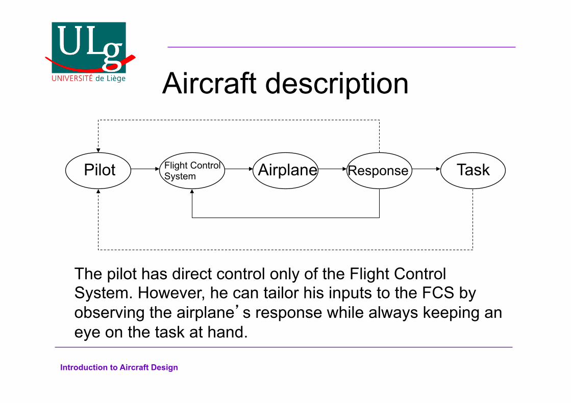
Aircraft description
Pilot Flight Control System Airplane Response Task
The pilot has direct control only of the Flight Control System. However, he can tailor his inputs to the FCS by observing the airplane’s response while always keeping an eye on the task at hand.

Introduction to Aircraft Design
Control Surfaces
Aircraft control is accomplished through control surfaces and power – Ailerons – Elevators – Rudder – Throttle
Control deflections were first developed by the Wright brothers from watching birds

Introduction to Aircraft Design
Modern control surfaces
Elevator
Rudder
Aileron
Elevon (elevator+aileron)
Rudderon (rudder+aileron)

Introduction to Aircraft Design
Other devices Flaps
Spoilers
Combinations of control surfaces and other devices: flaperons, spoilerons, decelerons (aileron and airbrake) Vectored thrust
Airbreak
Introduction to Aircraft Design
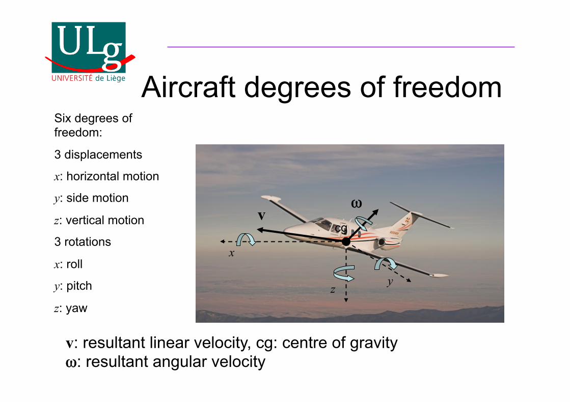
Aircraft degrees of freedom Six degrees of freedom:
3 displacements
x: horizontal motion
y: side motion
z: vertical motion
3 rotations
x: roll
y: pitch
z: yaw
x
z y
v ωω
v: resultant linear velocity, cg: centre of gravity ωω: resultant angular velocity
cg
Introduction to Aircraft Design
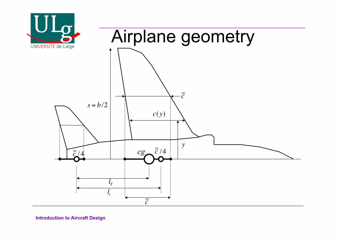
Airplane geometry
cg
c
c
c /4
s = b /2
c /4
lT
lt
y
c(y)
Introduction to Aircraft Design
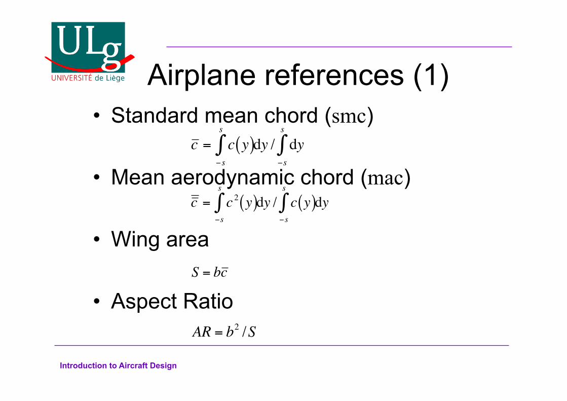
Airplane references (1) Standard mean chord (smc)
Mean aerodynamic chord (mac)
Wing area
Aspect Ratio
c = c 2 y( )−s
s
∫ dy / c y( )−s
s
∫ dy
c = c y( )−s
s
∫ dy / dy−s
s
∫
AR = b2 /S
S = bc

Introduction to Aircraft Design
Airplane references (2)
Centre of gravity (cg) Tailplane area (ST) Tail moment arm (lT) Tail volume ratio: A measure of the aerodynamic effectiveness of the tailplane
V T =ST lTSc

Introduction to Aircraft Design
Airplane references (3)
Fin moment arm (lF) Fin volume ratio
c /4
c /4cg
lF
lf
V F =SF lF
Sc
Introduction to Aircraft Design
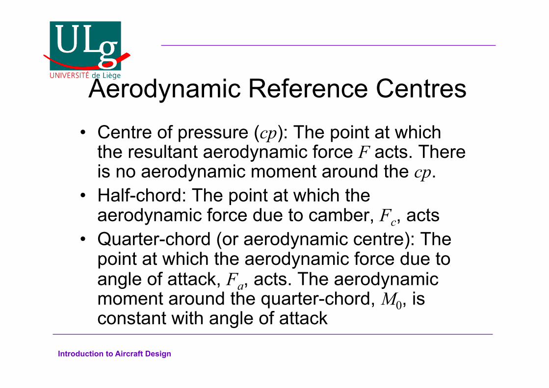
Aerodynamic Reference Centres Centre of pressure (cp): The point at which
the resultant aerodynamic force F acts. There is no aerodynamic moment around the cp. Half-chord: The point at which the
aerodynamic force due to camber, Fc, acts Quarter-chord (or aerodynamic centre): The
point at which the aerodynamic force due to angle of attack, Fa, acts. The aerodynamic moment around the quarter-chord, M0, is constant with angle of attack

Introduction to Aircraft Design
Airfoil with centres
ac
Dc cp D Da
Lc L La
Fc F Fa
L
D M0
c /4
c /2
hnc
c
Camber line
V0
By placing all of the lift and drag on the aerodynamic centre we move the lift and drag due to camber from the half-chord to the quarter chord. This is balanced by the moment M0
Introduction to Aircraft Design
Static Stability Most aircraft (apart from high performance
fighters) are statically stable Static stability implies:
– All the forces and moments around the aircraft’s cg at a fixed flight condition and attitude are balanced
– After any small perturbation in flight attitude the aircraft returns to its equilibrium position
The equilibrium position is usually called the trim position and is adjusted using the trim tabs
Introduction to Aircraft Design
Pitching moment equation
cg
mg
c
ac
LT
M0 MT
Lw
lT
hc
h0c
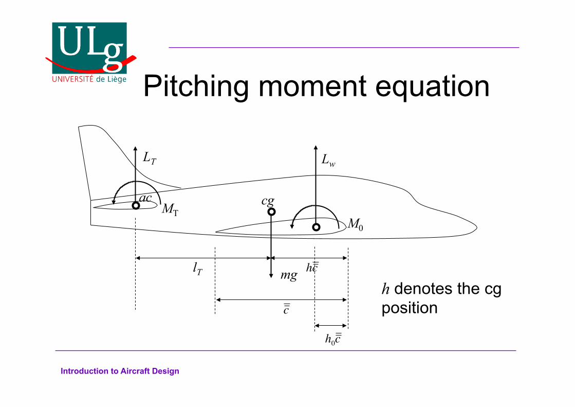
h denotes the cg position
Introduction to Aircraft Design
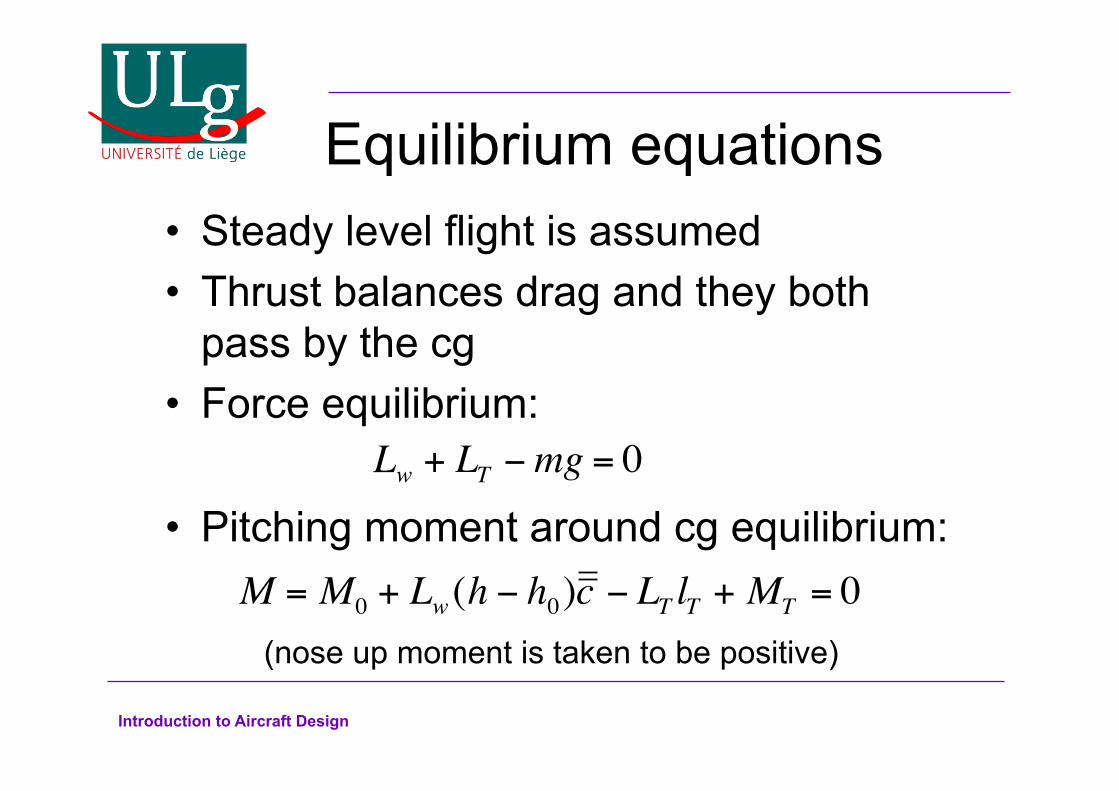
Equilibrium equations Steady level flight is assumed Thrust balances drag and they both pass by the cg Force equilibrium:
Pitching moment around cg equilibrium:
Lw + LT −mg = 0
M = M0 + Lw (h − h0)c − LT lT + MT = 0(nose up moment is taken to be positive)
Introduction to Aircraft Design
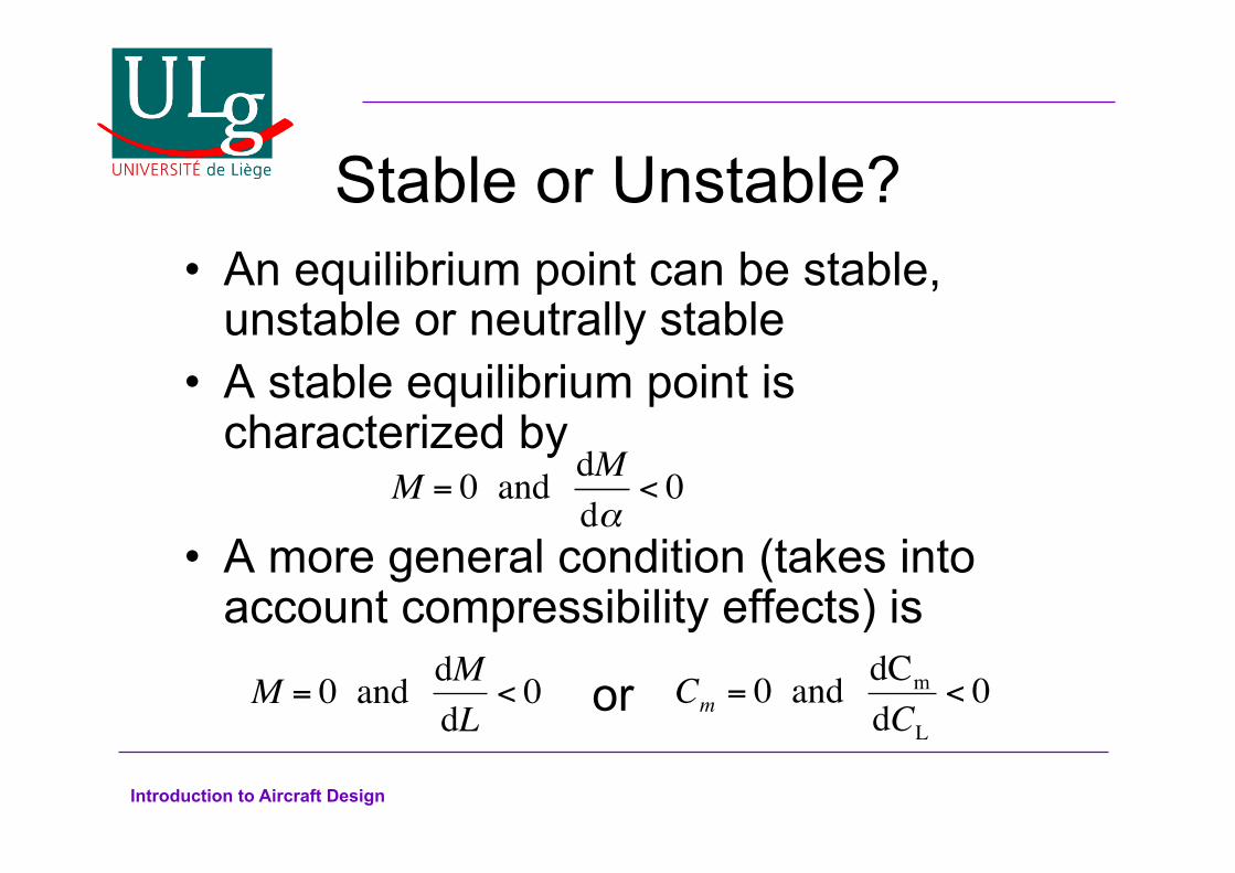
Stable or Unstable? An equilibrium point can be stable, unstable or neutrally stable A stable equilibrium point is characterized by
A more general condition (takes into account compressibility effects) is
M = 0 and dMdα
< 0
M = 0 and dMdL
< 0 or
Cm = 0 and dCm
dCL
< 0
Introduction to Aircraft Design
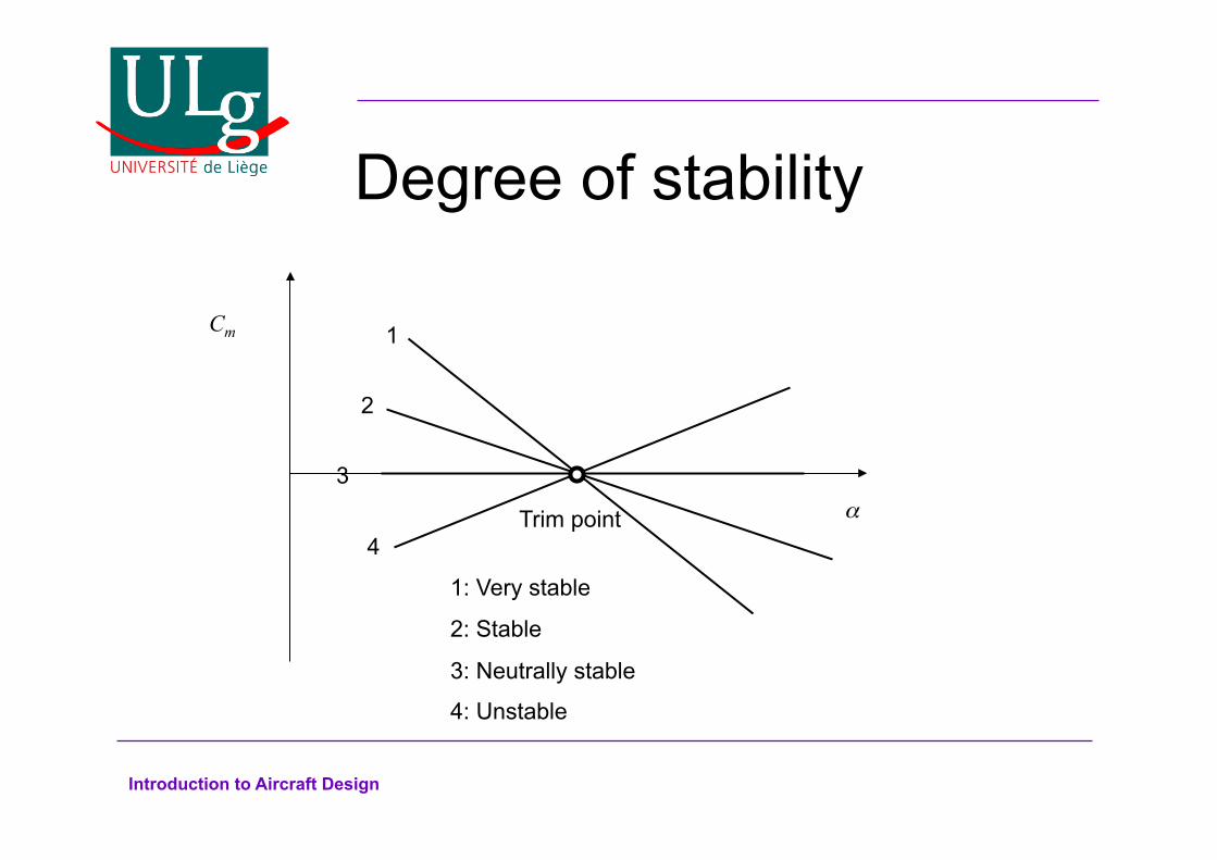
Degree of stability
Trim point
1
2
3
4 1: Very stable
2: Stable
3: Neutrally stable
4: Unstable
Cm
α

Introduction to Aircraft Design
Pitching moment stability (1) The pitching moment equation can be written as
Where
And the tailplane is assumed to be symmetric so that MT=0
Cm = Cm0+ CLw
(h − h0) −CLTV T = 0
Cm =M
12ρV0
2Sc , CLw
=Lw
12ρV0
2S, CLT
=LT
12ρV0
2ST
Introduction to Aircraft Design
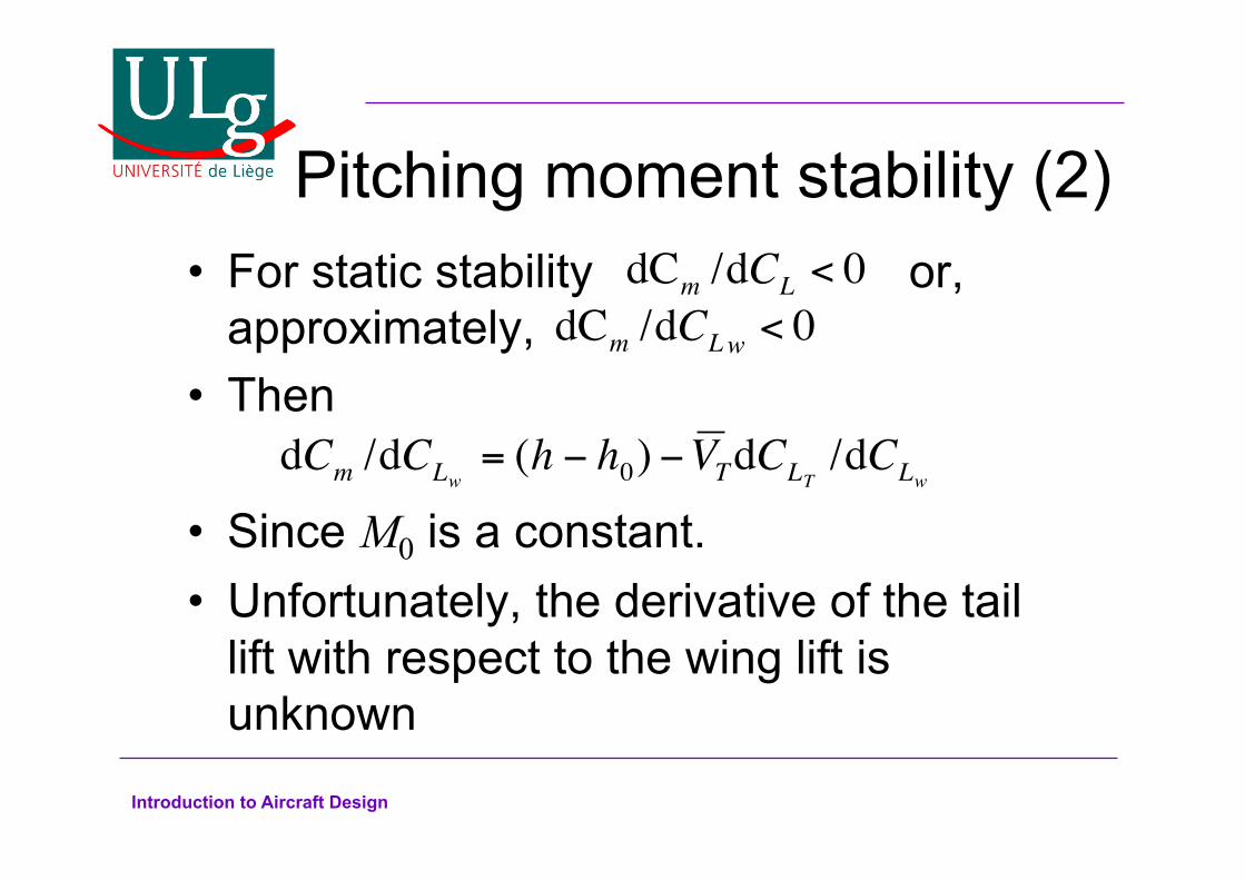
Pitching moment stability (2) For static stability or, approximately, Then
Since M0 is a constant. Unfortunately, the derivative of the tail lift with respect to the wing lift is unknown
dCm /dCL < 0
dCm /dCLw < 0
dCm /dCLw= (h − h0) −V TdCLT
/dCLw

Introduction to Aircraft Design
Wing-tail flow geometry
α V0
V0 α
ε αT
ηT
η
βη
Tailplane
Elevator Trim tab
Wing
The downwash effect of the wing deflects the free stream flow seen by the tailplane by an angle ε. Total angle of attack of tail: αT=α-ε+ηT
The total lift on the tailplane is given by:
CLT=α0 + a1αT + a2η + a3βη
Introduction to Aircraft Design
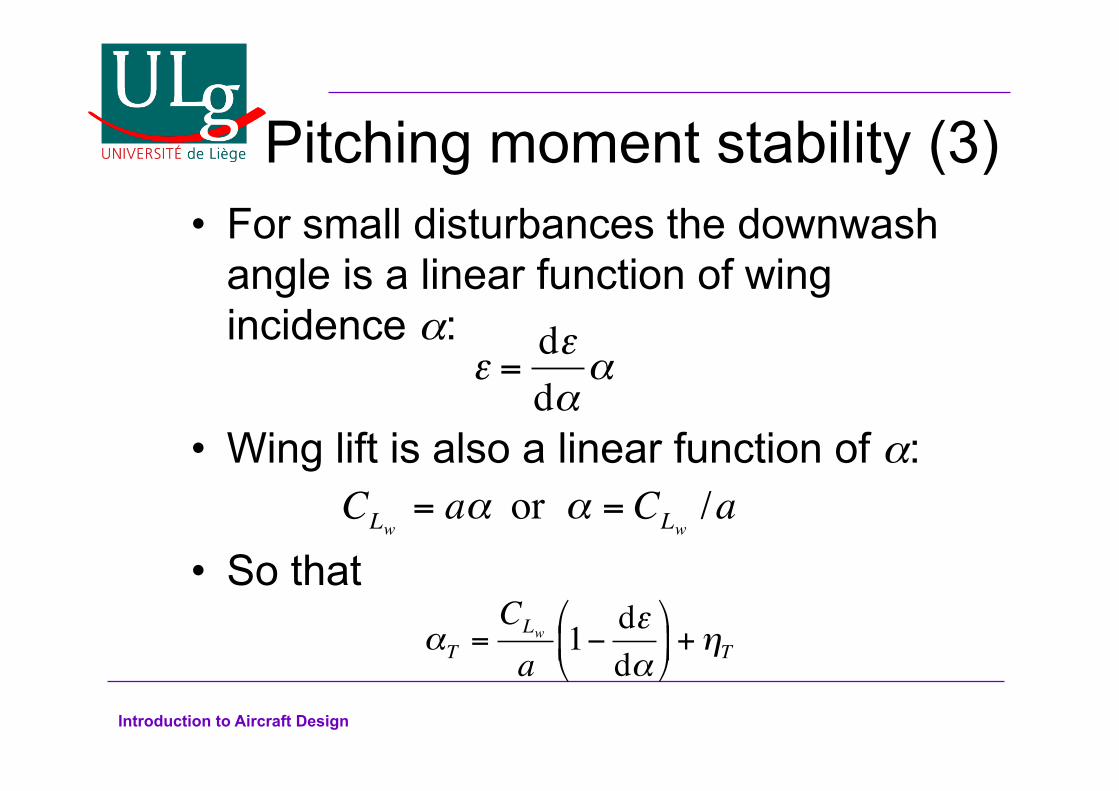
Pitching moment stability (3) For small disturbances the downwash angle is a linear function of wing incidence α:
Wing lift is also a linear function of α:
So that
ε =dεdα
α
CLw= aα or α = CLw
/a
αT =CLw
a1− dεdα
%
& '
(
) * +ηT

Introduction to Aircraft Design
Pitching moment stability (4)
The tail lift coefficient can then be written as
And the derivative of the pitching moment coefficient becomes
since ηT is a constant
CLT= CLw
a1a1− dεdα
%
& '
(
) * + a1ηT + a2η + a3βη
dCm
dCLw
= (h − h0) −V Ta1a1− dεdα
%
& '
(
) * + a2
dηdCLw
+ a3dβηdCLw
%
& ' '
(
) * *
Introduction to Aircraft Design
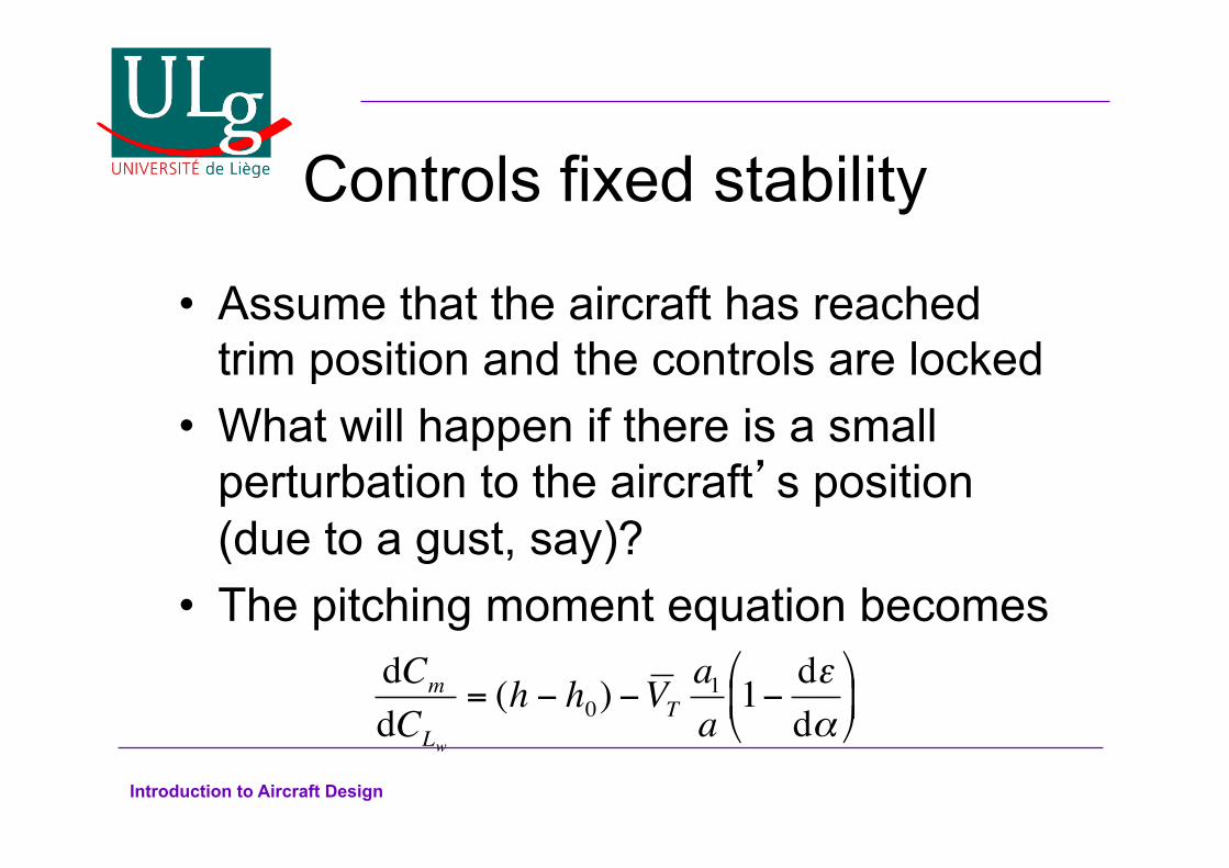
Controls fixed stability
Assume that the aircraft has reached trim position and the controls are locked What will happen if there is a small perturbation to the aircraft’s position (due to a gust, say)? The pitching moment equation becomes
dCm
dCLw
= (h − h0) −V Ta1a1− dεdα
%
& '
(
) *
Introduction to Aircraft Design
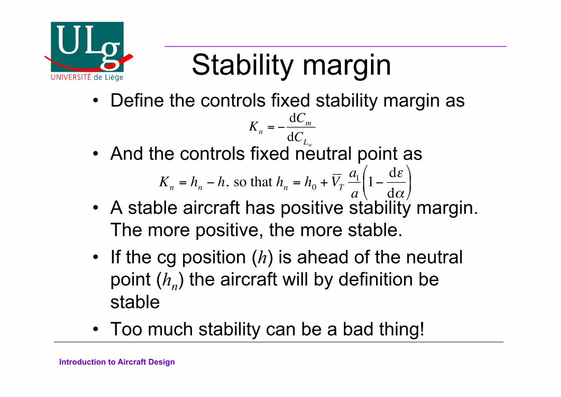
Stability margin Define the controls fixed stability margin as
And the controls fixed neutral point as
A stable aircraft has positive stability margin. The more positive, the more stable. If the cg position (h) is ahead of the neutral
point (hn) the aircraft will by definition be stable Too much stability can be a bad thing!
Kn = −dCm
dCLw
Kn = hn − h, so that hn = h0 + V Ta1
a1− dε
dα%
& '
(
) *
Introduction to Aircraft Design
Stability margin
Certification authorities specify that
at all times Of course, the stability margin can change:
– If fuel is used up – If payload is released:
Bombs Missiles External fuel tanks Paratroopers Anything else you can dump from a plane
Kn ≥ 0.05
Introduction to Aircraft Design
Controls Free Stability Pilots don’t want to hold the controls
throughout the flight. The trim tab can be adjusted such that, if the
elevator is allowed to float freely, it will at an angle corresponding to the desired trim condition. This is sometimes called a hands-off trim
condition. Therefore the pilot can take his hands off the
elevator control and the aircraft will remain in trim.
Introduction to Aircraft Design
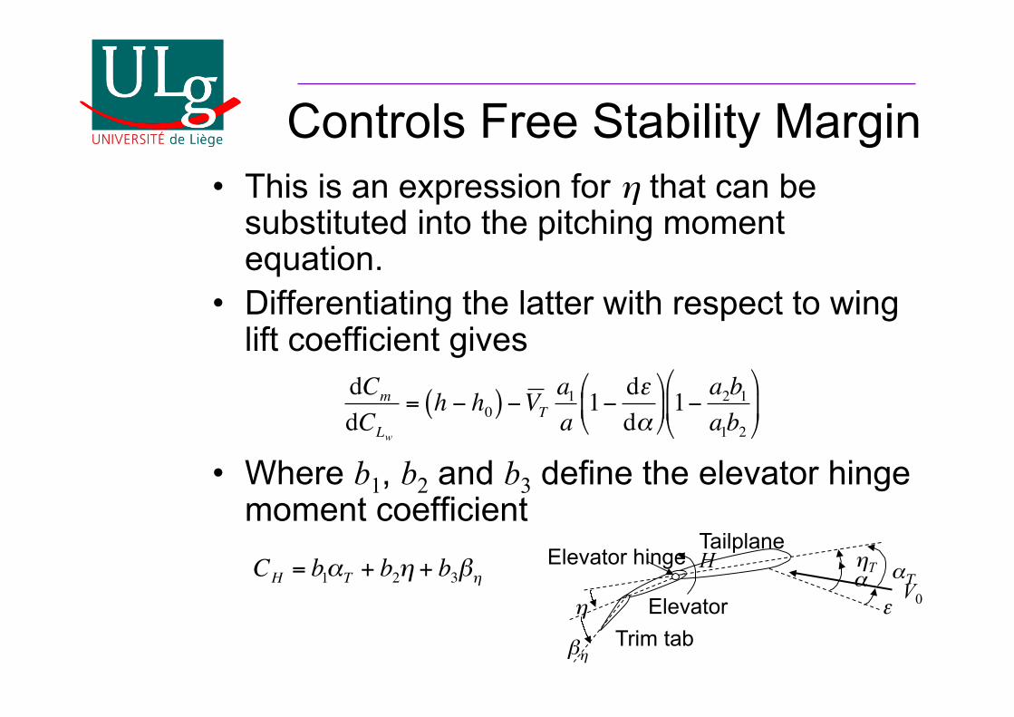
Controls Free Stability Margin This is an expression for η that can be
substituted into the pitching moment equation. Differentiating the latter with respect to wing
lift coefficient gives
Where b1, b2 and b3 define the elevator hinge moment coefficient
dCm
dCLw
= h − h0( ) −V Ta1a1− dεdα
%
& '
(
) * 1−
a2b1a1b2
%
& '
(
) *
CH = b1αT + b2η + b3βηV0 α
ε αΤ ηT
η βη
Tailplane
Elevator Trim tab
H Elevator hinge
Introduction to Aircraft Design
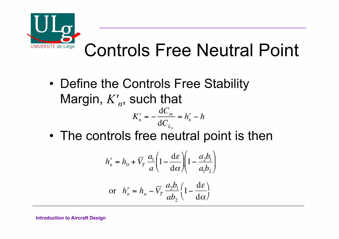
Controls Free Neutral Point
Define the Controls Free Stability Margin, K'n, such that
The controls free neutral point is then
" h n = h0 + V Ta1a1− dεdα
&
' (
)
* + 1−
a2b1a1b2
&
' (
)
* +
!Kn = −dCm
dCLw
= !hn − h
or " h n = hn −V Ta2b1
ab2
1−dεdα
& '
( )
Introduction to Aircraft Design
Discussion As with the controls fixed stability margin, the
controls free stability margin is positive when the aircraft is stable. Similarly, the centre of gravity position must
be ahead of the controls free neutral point if the aircraft is to be stable. Usually, the constants of the elevator and tab
are such that h'n>hn. An aircraft that is stable controls fixed will
usually be also stable controls free
Introduction to Aircraft Design
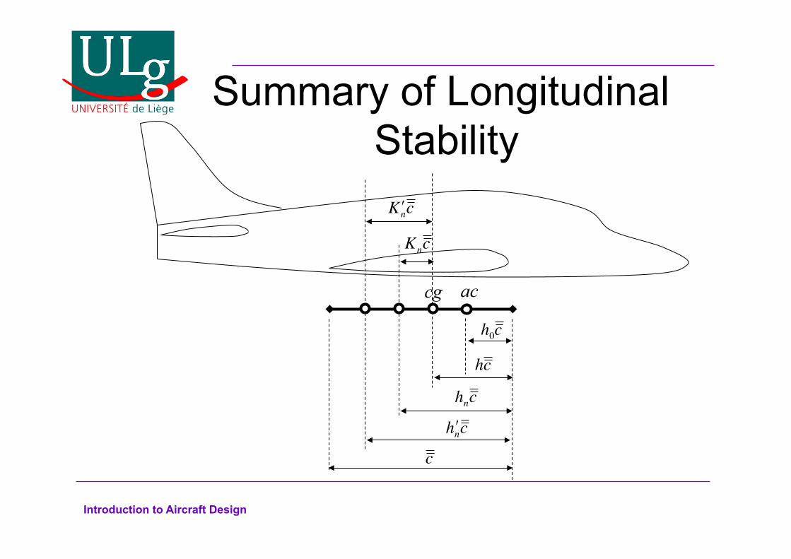
Summary of Longitudinal Stability
cg
c
hc
h0c
ac
hnc
" h nc
" K nc
Knc
Introduction to Aircraft Design
Lateral stability
There are two types of lateral motion for an aircraft: – Roll – Yaw
The aircraft must be stable in both of these directions of motion
Introduction to Aircraft Design
Roll Stability Mechanism There is no active stabilizing mechanism for
lateral stability (e.g. tail for longitudinal stability, rudder for yaw stability) Wing dihedral, Γ, is the only stabilizing
mechanism The higher the dihedral angle, the more
stable the aircraft As usual, too much stability can be a bad
thing
Introduction to Aircraft Design
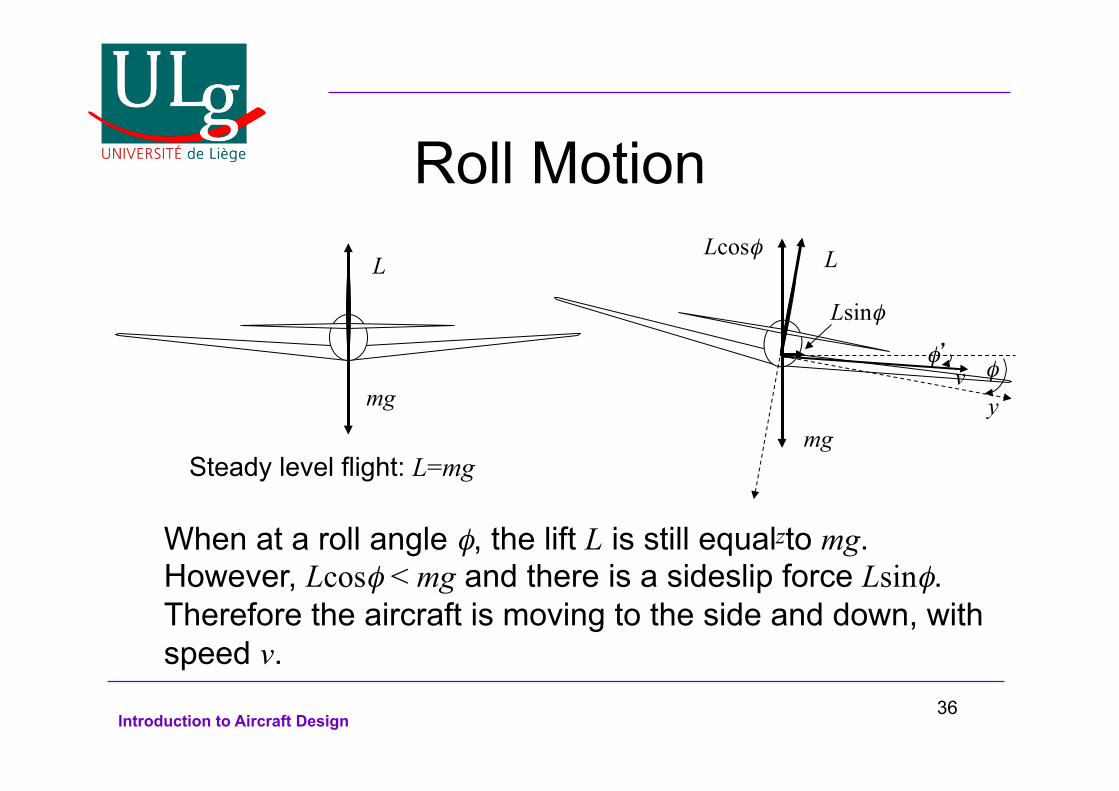
Roll Motion L
mg
Steady level flight: L=mg
L
mg
φ
Lcosφ
Lsinφ
v y
z When at a roll angle φ, the lift L is still equal to mg. However, Lcosφ < mg and there is a sideslip force Lsinφ. Therefore the aircraft is moving to the side and down, with speed v.
φ’
36
Introduction to Aircraft Design
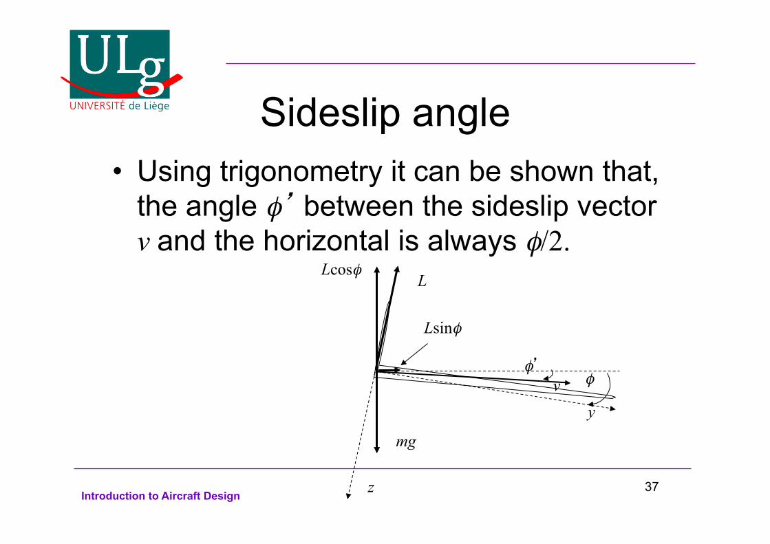
Sideslip angle Using trigonometry it can be shown that, the angle φ’ between the sideslip vector v and the horizontal is always φ/2.
L
mg
φ
Lcosφ
Lsinφ
v y
z
φ’
37
Introduction to Aircraft Design
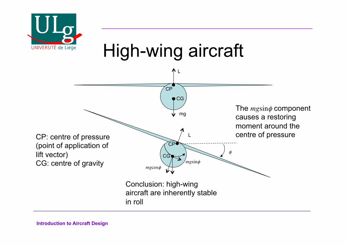
High-wing aircraft
CG
mg
L
mgcosφ
L
mgsinφ CG
CP
CP CP: centre of pressure (point of application of lift vector) CG: centre of gravity
The mgsinφ component causes a restoring moment around the centre of pressure
Conclusion: high-wing aircraft are inherently stable in roll
φ

Introduction to Aircraft Design
Low-wing aircraft
mg
mgcosφ
L
mgsinφ CG
CG
L
CP
CP
The mgsinφ component causes a destabilising moment around the centre of pressure
Conclusion: low-wing aircraft are inherently unstable in roll
φ

Introduction to Aircraft Design
Dihedral
Γ
Γ
High-wing aircraft: Dihedral reduces stability
Low-wing aircraft: Dihedral increases stability
Introduction to Aircraft Design
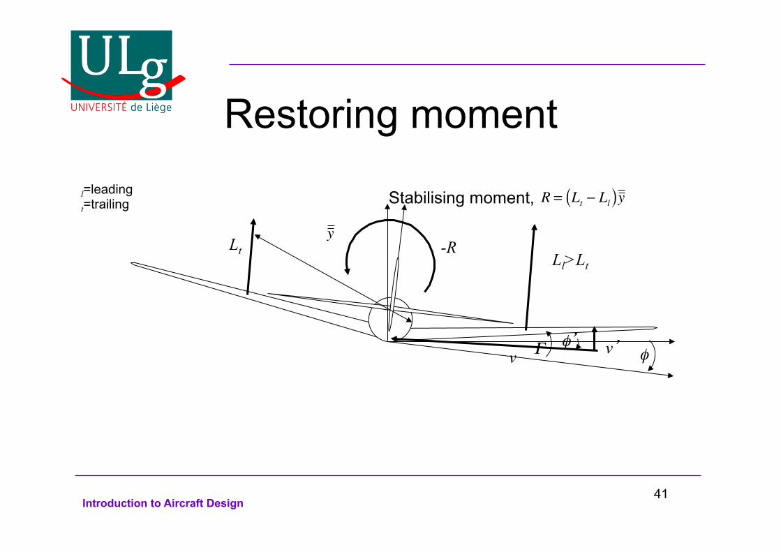
Restoring moment
φ φ’ Γ v v’
Ll>Lt Lt
Stabilising moment, l=leading t=trailing
R = Lt − Ll( )y
-R
y
41

Introduction to Aircraft Design
Roll stability For a stable aircraft in roll, dCR/dφ<0.
CR
42
Introduction to Aircraft Design
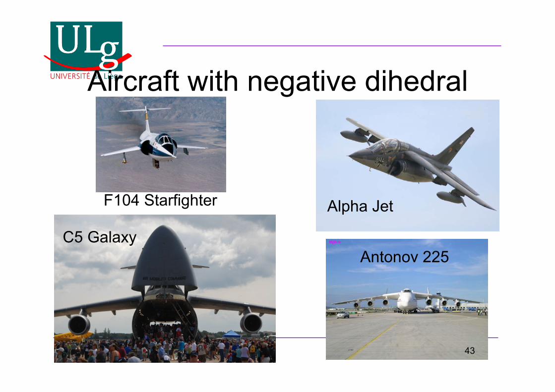
Aircraft with negative dihedral
F104 Starfighter
C5 Galaxy
Alpha Jet
Antonov 225
43
Introduction to Aircraft Design
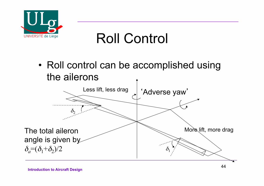
Roll Control
Roll control can be accomplished using the ailerons
δ1
δ2
The total aileron angle is given by δa=(δ1+δ2)/2
More lift, more drag
Less lift, less drag ‘Adverse yaw’
44
Introduction to Aircraft Design
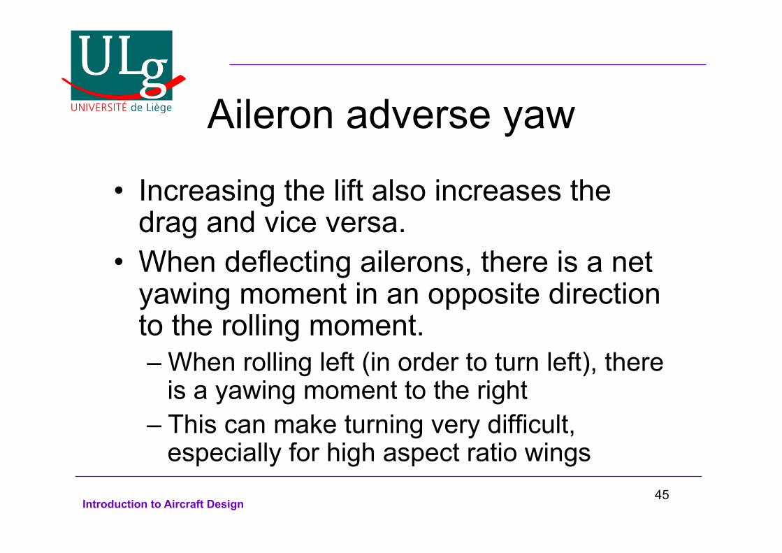
Aileron adverse yaw
Increasing the lift also increases the drag and vice versa. When deflecting ailerons, there is a net yawing moment in an opposite direction to the rolling moment. – When rolling left (in order to turn left), there
is a yawing moment to the right – This can make turning very difficult,
especially for high aspect ratio wings 45

Introduction to Aircraft Design
Roll control by spoilers
Another way of performing roll control is by deforming a spoiler on the wing towards which we want to turn. To turn left:
The spoiler decreases lift and increases drag. Now the yawing moment is in the same direction as the roll.
‘Proverse yaw’
46
Introduction to Aircraft Design
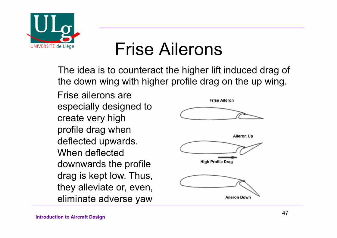
Frise Ailerons
Frise ailerons are especially designed to create very high profile drag when deflected upwards. When deflected downwards the profile drag is kept low. Thus, they alleviate or, even, eliminate adverse yaw
The idea is to counteract the higher lift induced drag of the down wing with higher profile drag on the up wing.
47
Introduction to Aircraft Design
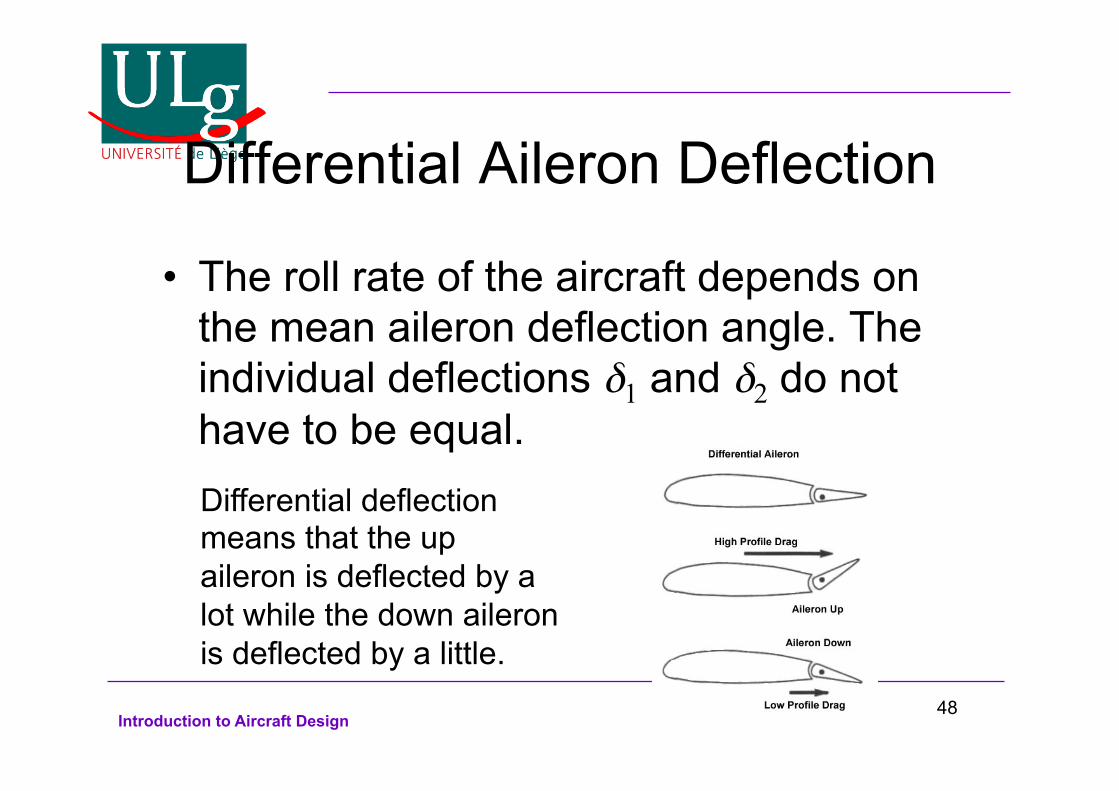
Differential Aileron Deflection
The roll rate of the aircraft depends on the mean aileron deflection angle. The individual deflections δ1 and δ2 do not have to be equal. Differential deflection means that the up aileron is deflected by a lot while the down aileron is deflected by a little.
48
Introduction to Aircraft Design
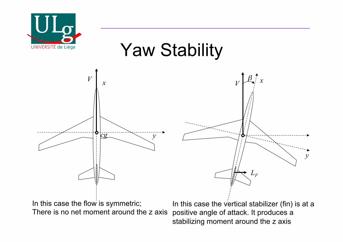
Yaw Stability
cg
V V β
y
x
y
x
In this case the flow is symmetric; There is no net moment around the z axis
In this case the vertical stabilizer (fin) is at a positive angle of attack. It produces a stabilizing moment around the z axis
LF
Introduction to Aircraft Design
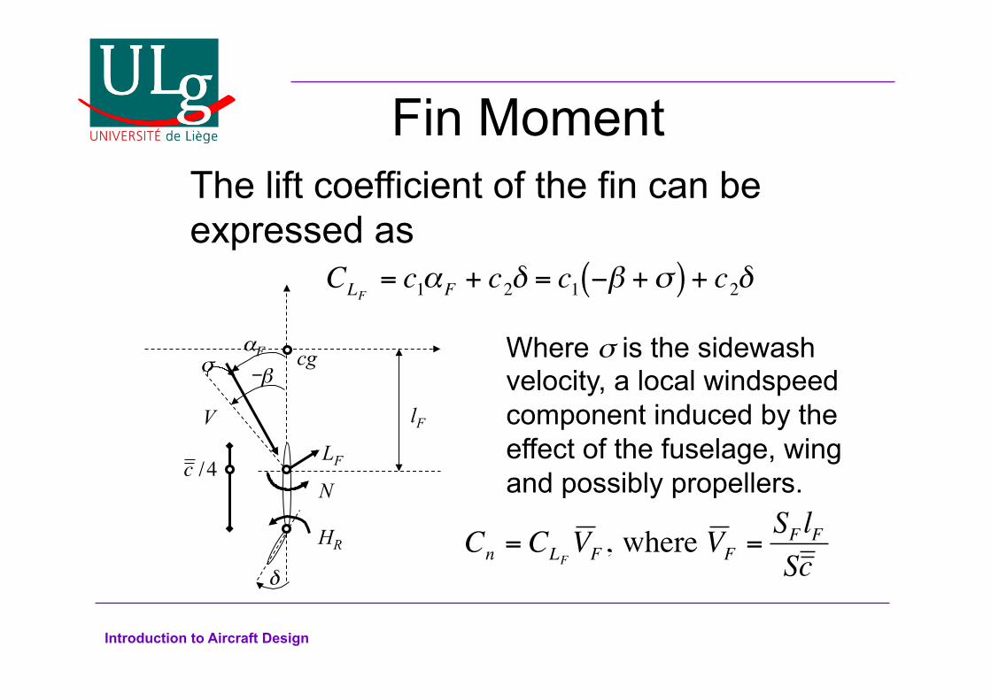
Fin Moment The lift coefficient of the fin can be expressed as
CLF= c1αF + c2δ = c1 −β +σ( ) + c2δ
cg
δ
V -β
LF
c /4
lF
σ Where σ is the sidewash velocity, a local windspeed component induced by the effect of the fuselage, wing and possibly propellers.
Cn = CLFV F , where V F =
SF lF
Sc
αF
HR N
Introduction to Aircraft Design
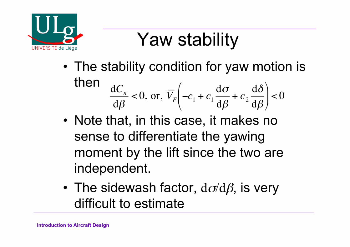
Yaw stability The stability condition for yaw motion is then
Note that, in this case, it makes no sense to differentiate the yawing moment by the lift since the two are independent. The sidewash factor, dσ/dβ, is very difficult to estimate
dCn
dβ< 0, or, V F −c1 + c1
dσdβ
+ c2dδdβ
&
' (
)
* + < 0

Introduction to Aircraft Design
Sidewash factor There are three main contributions to
sidewash: – Fuselage: It acts as a lifting body when at a yaw
angle – Wing: The flow over the wing is asymmetric. The
resulting sidewash is more pronounced for low aspect ratio sweptback wings.
– Propeller: The flow behind the propeller is also yawed, causing additional asymmetry.
Sidewash factors can be estimated most accurately by carefully designed wind tunnel experiments.
Introduction to Aircraft Design
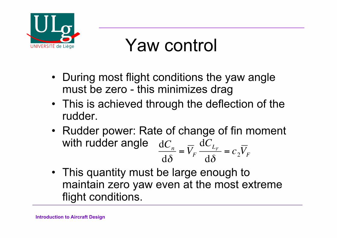
Yaw control
During most flight conditions the yaw angle must be zero - this minimizes drag This is achieved through the deflection of the
rudder. Rudder power: Rate of change of fin moment
with rudder angle
This quantity must be large enough to maintain zero yaw even at the most extreme flight conditions.
dCn
dδ= V F
dCLF
dδ= c2V F
Introduction to Aircraft Design
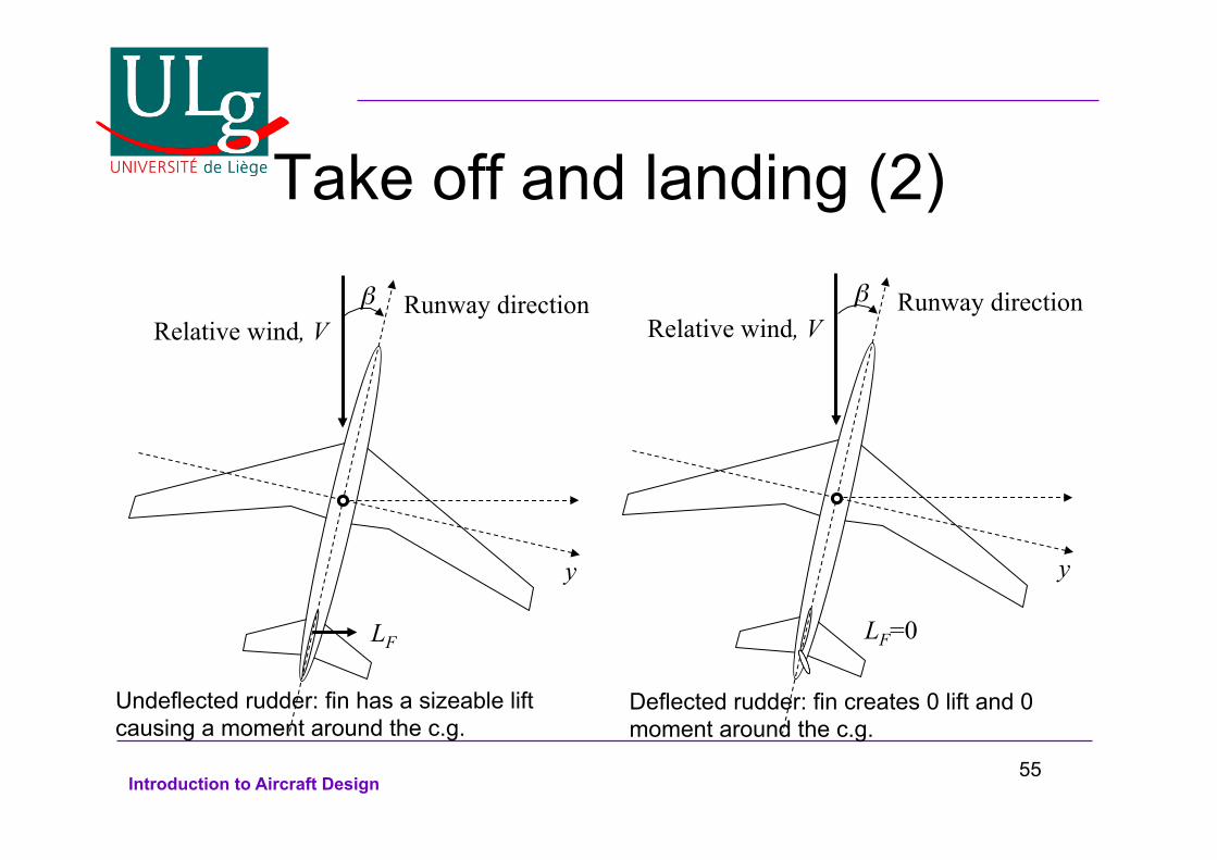
Take off and landing (1) During cruise, aircraft tend to turn towards the wind in order to minimize their drag. Therefore, the objective is to achieve 0o yaw. At take-off and landing this is not possible. The aircraft must remain aligned with the runway, even in the presence of a very strong sidewind. Therefore, the rudder must be able to provide a moment that can keep the aircraft aligned with the runway.
54
Introduction to Aircraft Design
Take off and landing (2)
Relative wind, V β
y
Runway direction
LF
Relative wind, V β
y
Runway direction
LF=0
Undeflected rudder: fin has a sizeable lift causing a moment around the c.g.
Deflected rudder: fin creates 0 lift and 0 moment around the c.g.
55
Introduction to Aircraft Design
Roll-Yaw coupling
Roll and yaw are always coupled. There are several reasons for the coupling: – Rolling produces sideslip – Ailerons cause adverse yaw – Dihedral cases additional coupling – Wingtip vortices cause additional coupling – Sweepback causes additional coupling – The fin causes additional coupling

Introduction to Aircraft Design
Summary on Control surfaces Elevators contribute to pitch stability and
control pitch angle. Rudder contributes to yaw stability and
controls yaw angle. Ailerons do not contribute to stability.
Furthermore, they control the roll rate, not the roll angle. There is no moment to balance the effect of the ailerons: They provide a constant moment that causes continuous roll rotation, whose rate also depends on the moment of inertia of the aircraft.
57
Introduction to Aircraft Design
More control surfaces
Elevons contribute to stability and control of both pitch and roll. They are ailerons that can also move up or down in unison, just like elevators.
Flaperons contribute to stability and control of both pitch and roll. They are ailerons that can also move downwards only, just like flaps.
Spoilerons contribute to stability and control of both pitch and roll. They are ailerons that can also move upwards only, just like spoilers.
58
Introduction to Aircraft Design
Modes of vibration of aircraft
Stability must also be investigated in a dynamic sense Aircraft have several modes of vibration:
– Longitudinal modes: Short Period Oscillation Phugoid
– Lateral modes: Spiral mode Roll subsidence Dutch roll

Introduction to Aircraft Design
Phugoid oscillations Phugoids are long period oscillations that occur
only in the longitudinal direction. The angle of attack is constant; the aircraft climbs
and descends in an oscillatory manner. Phugoids are also very lightly damped. Phugoid periods:
– Microlight aircraft: 15-25s – Light aircraft: over 30s – Jet aircraft: minutes
Phugoids are neutralized by re-trimming the aircraft in the new flight condition.

Introduction to Aircraft Design
Phugoid Videos
Introduction to Aircraft Design
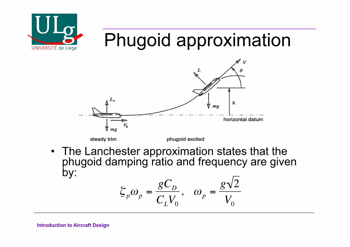
Phugoid approximation
The Lanchester approximation states that the phugoid damping ratio and frequency are given by:
ζ pω p =gCD
CLV0
, ω p =g 2V0

Introduction to Aircraft Design
More about Phugoids Phugoid period
increases with airspeed. Phugoid damping increases with airspeed.
Compressibility effects Period and damping
for a Boeing 747 at several altitudes and Mach numbers
Nhalf= number of periods until the amplitude is halved

Introduction to Aircraft Design
Short period oscillations
Short period oscillations have a much higher frequency than Phugoids. They are driven by the angle of attack (in
french they are called oscillations d’incidence). Speed changes are negligible They occur after abrupt input changes.
Slower input changes do not cause significant short period oscillations

Introduction to Aircraft Design
Short Period Dependencies The period generally
decreases with airspeed. The damping can either decrease or increase
Compressibility effects Period and damping
for a Boeing 747 at several altitudes and Mach numbers

Introduction to Aircraft Design
Spiral mode This mode is quite visible in the impulse
response of the lateral equations It is the non-oscillatory mode with large time
constant It is mainly a yaw movement with a little roll This mode can be stable or unstable. It is
unstable quite often but that is not a problem because of its large time constant
The typical half-life of a spiral mode is of the order of a minute.
The spiral movement is usually stopped by a corrective control input
Introduction to Aircraft Design
Spiral Mode Video
Introduction to Aircraft Design
Roll subsidence
An impulse aileron input will start the aircraft rolling. In general, the aircraft will stop rolling with
time (i.e. the roll rate becomes zero after sufficient time) The aircraft will find itself at a roll angle which
depends on how fast the roll rate tends to zero. This phenomenon is called roll subsidence.

Introduction to Aircraft Design
Roll Subsidence Video
Introduction to Aircraft Design
Dutch Roll The name Dutch Roll is due to the fact that the
phenomenon resembles an ice skating figure called Dutch Roll.
The centre of gravity remains on a straight trajectory while the roll and yaw angles oscillate.
The roll velocity also oscillates but the yaw velocity is very low.
The Dutch roll damping increases with airspeed while its period first increases and then decreases with airspeed.
The typical period of a Dutch roll is in the order of 5 to 10 seconds.

Introduction to Aircraft Design
Dutch Roll Videos
Introduction to Aircraft Design
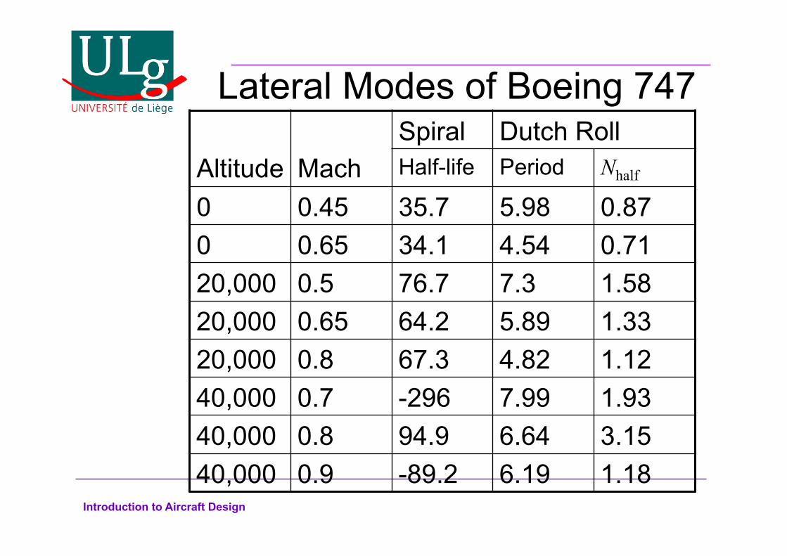
Lateral Modes of Boeing 747 Altitude
Mach
Spiral Dutch Roll Half-life Period Nhalf
0 0.45 35.7 5.98 0.87 0 0.65 34.1 4.54 0.71 20,000 0.5 76.7 7.3 1.58 20,000 0.65 64.2 5.89 1.33 20,000 0.8 67.3 4.82 1.12 40,000 0.7 -296 7.99 1.93 40,000 0.8 94.9 6.64 3.15 40,000 0.9 -89.2 6.19 1.18